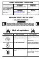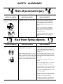
1
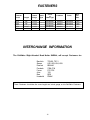
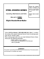
STEEL DRIVER SERIES
Operation, Maintenance, and Parts Manual for SHBN4
BRAD NAILER
Specifications
MODEL
SHBN4
AIR INLET ........................................................ 1/4" NPT
WEIGHT ........................................................... 2 lbs. 10 ozs.
LENGTH ........................................................... 7.9"
HEIGHT ............................................................ 7.5"
MAXIMUM PRESSURE................................... 125 PSI
PRESSURE RANGE ........................................ 65-100 PSI
FASTENER LENGTHS ..................................... 1/4" - 1 1/4"
MAGAZINE CAPACITY ................................... 100 Brads
SCFM REQUIRED @ 90 PSI ........................... Every 10 Fasteners
Delivered Per Minute
Requires .28 SCFM
MINIMUM COMPRESSOR HP
REQUIRED TO OPERATE ............................... 3/4 HP
(TANK MOUNTED)
This manual contains information that is important for you to know and understand.
This information relates to protecting YOUR SAFETY and PREVENTING EQUIPMENT
PROBLEMS. PLEASE READ THIS MANUAL.
DeVilbiss Air Power Company • 213 Industrial Drive • Jackson, TN 38301-9615
MGP-SHBN4-1A
9/25/97
TABLE OF CONTENTS
PAGE
Tool Specifications ....................................................................................... Front Cover
Table of Contents .................................................................................................... 2
Limited Warranty ..................................................................................................... 3
Safety Guidelines .................................................................................................... 4
Warning Chart ......................................................................................................... 4-6
Lubrication and Maintenance .................................................................................. 7-8
Recommended Hook-up ......................................................................................... 8
Contact Trip Safety Mechanism ............................................................................... 9
A. Operating A Contact Trip Tool
B. Checking The Operation Of Contact Trip Safety Mechanism
Loading The Tool ................................................................................................. 10
Operating the Tool................................................................................................ 10-11
Clearing A Jam From The Tool............................................................................. 11
Trouble Shooting Guide ....................................................................................... 12
Exploded View ..................................................................................................... 13
Parts List ............................................................................................................. 14
Parts Kits ............................................................................................................. 14
Fasteners ............................................................................................................. 15
Toll-Free 800 Number .................................................................................
2
Back Cover
LIMITED WARRANTY
ONE YEAR FROM DATE OF PURCHASE
All merchandise manufactured by DeVilbiss Air Power Company is warranted to be free of defects in workmanship
and material which occur during the first year from the date of purchase by the original purchaser (initial user). Products
covered under this warranty include: air compressors, *air tools, accessories, service parts, pressure washers, and
generators used in consumer applications (i.e., personal residential household usage only).
Air compressors, *air tools, accessories, service parts, pressure washers, and generators used in commercial
applications (income producing) are covered by a 90 day warranty.
DeVilbiss Air Power will repair or replace, at DeVilbiss's option, products or components which have failed within the
warranty period. Repair or replacement, and service calls on 60 and 80 gallon air compressors, will be handled by
Authorized Warranty Service Centers and will be scheduled and serviced according to the normal work flow and
business hours at the service center location, and depending on the availability of replacement parts.
All decisions of DeVilbiss Air Power Company with regard to this policy shall be final.
This warranty gives you specific legal rights, and you may also have other rights which vary from state to state.
RESPONSIBILITY OF ORIGINAL PURCHASER (Initial User):
o
o
o
o
o
Retain original cash register sales receipt as proof of purchase for warranty work.
Use reasonable care in the operation and maintenance of the product as described in the Owners Manual(s).
Deliver or ship the product to the nearest DeVilbiss Air Power Authorized Warranty Service Center.
Freight costs, if any, must be paid by the purchaser.
Air compressors with 60 and 80 gallon tanks only will be inspected at the site of installation. Contact the nearest
Authorized Warranty Service Center, that provides on-site service calls, for service call arrangement.
If the purchaser does not receive satisfactory results from the Authorized Warranty Service Center, the purchaser
should contact DeVilbiss Air Power Company.
THIS WARRANTY DOES NOT COVER:
o
o
o
o
o
o
o
o
o
Merchandise sold as reconditioned, floor models and/or display models. Any damaged or incomplete equipment
sold "as is".
Merchandise used as "rental" equipment.
Merchandise that has become inoperative because of ordinary wear, misuse, freeze damage, use of improper
chemicals, negligence, accident, improper and/or unauthorized repair or alterations including failure to operate
the product in accordance with the instructions provided in the Owners Manual (s) supplied with the product.
*Air Tools: O-Rings and driver blades are considered ordinary wear parts, therefore, they are warranted for a
period of 45 days from the date of purchase.
An air compressor that pumps air more than 50% during a one hour period is considered misuse because
the air compressor is undersized for the required air demand. Maximum compressor pumping time per hour is
30 minutes.
Merchandise sold by DeVilbiss Air Power which has been manufactured by and identified as the product of
another company. The product manufacturer's warranty will apply.
Repair and transportation costs of merchandise determined not to be defective.
Cost associated with assembly, required oil, adjustments or other installation and start-up cost.
ANY INCIDENTAL, INDIRECT OR CONSEQUENTIAL LOSS, DAMAGE, OR EXPENSE THAT MAY RESULT FROM
ANY DEFECT, FAILURE OR MALFUNCTION OF THE PRODUCT. Some states do not allow the exclusion or limitation
of incidental or consequential damages, so the above limitation or exclusion may not apply to you.
IMPLIED WARRANTIES, INCLUDING THOSE OF MERCHANTABILITY AND FITNESS FOR A PARTICULAR
PURPOSE, ARE LIMITED TO ONE YEAR FROM THE DATE OF ORIGINAL PURCHASE. Some states do not allow
limitations on how long an implied warranty lasts, so the above limitations may not apply to you.
DeVilbiss Air Power Company
213 Industrial Drive • Jackson, TN 38301-9615 • Telephone: 1-800-888-2468 , Ext. 2 • FAX: 1-800-888-9036
Form: SP-100-E - 4/25/96
3
SAFETY GUIDELINES - DEFINITIONS
This manual contains information that is important for you to
know and understand. This information relates to protecting YOUR
SAFETY and PREVENTING EQUIPMENT PROBLEMS. To help you
recognize this information, we use
symbols to the right. Please read
the manual and pay attention to
these sections.
URGENT SAFETY INFORMATION - A HAZARD
THAT WILL CAUSE SERIOUS INJURY OR LOSS
OF LIFE.
IMPORTANT SAFETY INFORMATION - A
HAZARD THAT MIGHT CAUSE SERIOUS
INJURY OR LOSS OF LIFE.
Information for preventing damage to
equipment.
Information that you should pay special
attention to.
IMPORTANT SAFETY INSTRUCTIONS
• SAVE THESE INSTRUCTIONS •
IMPROPER OPERATION OR MAINTENANCE OF THIS PRODUCT COULD RESULT
IN SERIOUS INJURY AND PROPERTY DAMAGE. READ AND UNDERSTAND ALL
WARNINGS AND OPERATING INSTRUCTIONS BEFORE USING THIS EQUIPMENT.
Risk of explosion.
HAZARD TO LOOK FOR
Compressed Gas
WHAT COULD HAPPEN
HOW TO PREVENT IT
Oxygen will react with oil in tool causing
an explosion. Flammable gases will ignite from sparking and cause the tool to
explode.
Do not use any type of flammable
gases or oxygen as a power source
for the tool.
Use only filtered, lubricated, regulated compressed air .
Excessive Operating Pressure
THE TOOL COULD EXPLODE!
Operate tool with clean, dry air regulated to 100 psi pressure maximum.
Unsuitable Cleaning Solvents
Flammable vapors in the tool will ignite
by a spark and could cause the tool to
explode!
Never use gasoline or other flammable liquids to clean the tool.
Use non-flammable cleaning or
degreasing materials.
4
SAFETY GUIDELINES
DANGER
Read these warnings carefully. Failure to follow
warnings will result in severe injury or death!
Risk of head injury.
HAZARD TO LOOK FOR
Injury to eyes, head and hearing
WHAT COULD HAPPEN
HOW TO PREVENT IT
Metal fragments, fasteners, or other material could be projected against head or
into eyes. Continued exposure to an
operating tool can result in permanent
hearing damage.
Always wear ANSI approved Z87 safety
glasses, Z89.1 head protection and
S3.19 hearing protection.
Risk of puncture injury.
HAZARD TO LOOK FOR
Unsafe operation and improper
handling of tool.
WHAT COULD HAPPEN
HOW TO PREVENT IT
A fastener could accidentally be driven if
the contact trip safety mechanism is not
working.
Do not remove, modify or defeat contact safety device.
Damage to the tool or to the contact trip
safety mechanism can result from improper handling, resulting in unsafe operation.
Do not use the tool if any shields or
guards are removed or altered.
Death or a serious puncture would could
occur if the contact trip bumps something
or someone while holding the tool with
the trigger depressed.
Never carry the tool by the hose or pull
the hose to move the tool or a compressor. Keep hoses away from heat, oil and
sharp edges. Replace any damaged,
weak or worn hoses.
Always check contact trip safety mechanism of the tool before each use.
CONTINUED NEXT PAGE
5
SAFETY GUIDELINES
Risk of puncture injury.
HAZARD TO LOOK FOR
Connecting and Disconnecting
Air Hose
WHAT COULD HAPPEN
HOW TO PREVENT IT
Accidental discharge of a fastener can
occur.
Hold tool by the handle and keep trigger
and contact trip safety mechanism from
contacting objects or parts of the body
when connecting or disconnecting air
supply.
Disconnect air hose before loading fasteners, removing a jammed fastener,
servicing the tool, or moving the tool to
another work area.
Do not use a check valve or any other
fitting which allows air to remain in the
tool.
Risk from flying objects.
HAZARD TO LOOK FOR
WHAT COULD HAPPEN
HOW TO PREVENT IT
Injury to self or others in the work
area.
Fasteners could ricochet or be propelled
causing injury to self or others.
Pay attention to others in the work area to
assure that they are protected from possible accidental discharge of fastener, or
projected fragments of work material, fasteners, etc.
When working along edges or next to
voids in work surface, the contact trip
safety mechanism could be depressed
and allow the tool to discharge a fastener
into the air or through thin work materials.
Provide ANSI approved Z87 safety
glasses, Z89.1 head protection, and S3.19
hearing protection to self and others in the
work area.
Never point discharge of tool at self or
others.
Do not pull trigger unless tool contact
safety device is against work surface.
Never attempt to drive fasteners into hard
surfaces such as steel, concrete, or tile.
Take care to avoid driving a fastener on top
of another fastener.
Before operating tool, be certain that work
surfaces are strong enough and thick
enough to contain entire fastener.
Position tool carefully so that fasteners
will be delivered to the proper location.
6
LUBRICATION AND MAINTENANCE
NOTE
Many air tool users find it convenient to use an Oiler to
help provide oil circulation through tool. An Oiler also
increases the efficiency and useful life of the tool. An
oiler is recommended for tools that receive heavy or
constant use. Check oil level in the oiler daily.
(See Figure 2)
Do not store the tool in cold weather. Frost or ice can
form on the operating valves or mechanisms and the
tool may not operate correctly.
Many air tool users find it convenient to use a Filter to
remove liquid and solid impurities which can rust or
"gum up" internal parts of the tool. A Filter also increases the efficiency and useful life of the tool. Drain
water from the filter periodically. (See Figure 3)
Figure 1
In cold weather operation (near or below freezing), DO
NOT USE a permanent antifreeze such as ethylene
glycol for a cold weather lubricant. This type of anitfreeze
will damage o-rings and seals of the tool.
NOTE
Proper lubrication is the owner's responsibility. Failure to lubricate the tool properly will dramatically shorten
the life of the tool and void your warranty.
Figure 2
Regulator
Your tool requires lubrication before you use it for the
first time and before and after each additional use. If
an Oiler is used, manual lubrication through the air inlet
is not required on a daily basis. Lubrication prevents
wear and prevents rust from forming.
Oiler
Figure 3
1. Disconnect the air supply from the tool before
manually lubricating.
Regulator
2. Turn the tool so the air inlet is facing up and put one
drop of Air Tool Oil, high speed spindle oil, such as
Unocal RX22, or 3-in-1 oil into the air inlet. DO NOT
USE detergent oil or additives. Operate the tool
briefly after adding oil. (See Figure 1)
Filter
DO NOT OVER LUBRICATE AIR TOOL.
NOTE
Excessive oil will damage o-rings and seal of
tool. If in-line oiler is used, manual lubrication through the air inlet is not required on a
daily basis.
3. Wipe off excessive oil at the exhaust.
7
LUBRICATION AND MAINTENANCE
Always connect the Female Quick Coupler to the air hose.
Never connect the Female Quick Coupler to the tool.
Do not use any type of flammable gases or oxygen as a
power source for the tool. Use filtered, lubricated, regulated compressed air only. Use of compressed gas
instead of compressed air may cause the tool to explode
and cause death or serious personal injury.
Do not use a check valve or any other fittings which will
allow air to remain in the tool. Serious personal injury
could occur.
Never carry the tool by the hose or pull the hose to move
the tool or a compressor. Keep hoses away from
heat, oil, and sharp edges. Replace any damaged,
weak or worn hoses.
Use a Pressure Regulator on your compressor with an
operating pressure of 0-125 PSI. A Pressure Regulator
is required to control the operating pressure of your tool.
The air compressor must be able to maintain a minimum of
65 PSI when the tool is being used. An inadequate air supply
can cause a loss of power or inconsistent operation.
NOTE
For better performance, install a 3/8" Quick Connector
(1/4" NPT threads) with an inside diameter of .315 (8
mm) on your Tool and a 3/8" Quick Coupler on the air
hose. A minimum of 3/8" I.D. air hose with a rated
working pressure of 150 PSI or above should be used.
RECOMMENDED HOOK-UP
The following illustration shows the proper hook-up which will help prolong the life of the Tool.
NAILER
MALE
QUICK
CONNECTOR
(Supplied with Tool)
MALE
QUICK
CONNECTOR
FEMALE
QUICK
COUPLER
OILER
FILTER
AIR
COMPRESSOR
AIR
HOSE
(3/8" I.D.)
FEMALE
QUICK
COUPLER
8
REGULATOR
CONTACT TRIP SAFETY MECHANISM
3.
The trigger is released after each fastener is driven.
4.
Move the tool to the next desired fastener location
and repeat the procedure above.
CHECKING THE OPERATION OF
CONTACT TRIP SAFETY MECHANISM
Never keep the trigger pulled on contact trip tools
when carrying or holding the tool. Death or a serious
puncture wound could occur if the contact trip bumps
something or someone.
Check the operation of the contact trip safety
mechanism often. Do not use the tool if the
contact trip safety mechanism is not working
correctly.
Keep your hands and body away from the fastener
discharge area of the tool. Serious personal injury
could occur.
1. Disconnect the air supply from the tool.
2. Remove all fasteners from the magazine.
3. Make sure the trigger and contact trip safety mechanism
move up and down without any sticking or binding.
Do not hold the tool against the work surface with
extra force. Allow the tool to drive the fastener.
Do not use the contact trip mechanism as a means of
discharging a fastener because:
Make sure not to pull the trigger or depress the
contact trip safety mechanism when connecting
the tool to an air compressor. Serious personal
injury can occur if the tool cycles.
1. It could result in personal injury
2. It could result in an accidental release of a
fastener.
3. It may cause damage to the mechanism.
4. It could result in improper placement of fastener
in work piece.
4. Reconnect air supply to the tool.
5. Depress the contact trip safety mechanism against the
work surface without pulling the trigger. The tool must
not cycle. Do not use the tool if a cycle occurs.
CONTACT TRIP
Your SHBN4 Slight-Headed Brad Nailer is a contact trip
operated tool. When the operator depresses the contact trip
safety mechanism against the work surface and then pulls
the trigger, a fastener will be driven.
6. Hold the tool clear of the work surface. The contact
trip safety mechanism should return to its original
down position. Pull the trigger. The tool must not
cycle. Do not use the tool if a cycle occurs.
OPERATING A CONTACT TRIP TOOL:
1.
Requires finger to be off the trigger and the nose of
the tool to be placed on the work surface.
2.
The contact trip safety mechanism is then depressed
against the work surface and the trigger is pulled to
drive a fastener.
7. Depress the contact trip safety mechanism against
the work surface. Pull the trigger. The tool must
cycle.
9
LOADING THE TOOL
Disconnect tool from air supply before adjusting,
clearing jams, servicing, relocating and during
non-operation.
Handle the tool carefully. Respect the tool as a
working implement and always assume the tool
contains fasteners and is ready to operate.
a. Never use the tool as a toy and engage in horseplay.
b. Never aim or point the tool at anyone. The tool
may contain fasteners.
c. Always keep people and animals at a safe distance from the work area in case of accidental
discharge of fasteners.
d. Never pull the trigger unless the nose of the tool
is against the work surface.
e. Do not pull the trigger or depress the contact trip
when loading the Tool.
Never place your hand, or any part of your body, in
the fastener discharge area of the tool when air
supply is connected to the tool. Serious personal
injury may occur.
1. Disconnect air hose.
NOTE
2. Pull up on the Stopper #56. Pull back on Reel Plate #50
to open magazine. (Items 50 & 56 - Page 13)
Use DeVilbiss Air Power fasteners or equivalent for
proper performance of tool. See page 15 for
fastener information.
3. Insert a stick of fasteners into the magazine. Make
sure the pointed ends of the fasteners are resting on the
bottom edge of the magazine. Also make sure fasteners
are not dirty or damaged. Use DeVilbiss fasteners or
equivalent for proper fastener performance.
4. Push the magazine cover forward until the reel plate
catches under stopper.
OPERATING THE TOOL
READ THIS MANUAL AND UNDERSTAND ALL
SAFETY WARNINGS AND INSTRUCTIONS BEFORE OPERATING TOOL.
Disconnect tool from air supply before adjusting,
clearing jams, servicing, loading, relocating and during non-operation.
NOTE
Check and replace any damaged or worn components on the tool. The safety warning labels on the tool
must also be replaced if they are not legible.
Protect your eyes and ears. Wear Z87 safety
glasses with side shields. Wear hearing protection.
Employers and users are responsible for ensuring
the user or anyone near the tool wear this safety
protection.
10
OPERATING THE TOOL
1. Add one drop of DeVilbiss DV1719-01 Air Tool Oil, high
speed spindle oil such as Unocal RX22, or 3-in1 oil
into the air inlet.
5. Load fasteners into your tool following the instruction in
this manual.
6. Reconnect the air hose to the tool.
2. Attach a Quick Connect Fitting to the tool.
7. Test for proper fastener penetration by driving fasteners
into a sample piece of material. If the fasteners do not
achieve the desired penetration, adjust the air pressure
to a lower or higher setting until the desired penetration
is achieved. Do not exceed 100 psi at the tool.
3. Connect the Tool to an air compressor using a 3/8" I.D.
hose. (The magazine must be empty of all fasteners). Make sure the hose has a rated working pressure
exceeding 150 PSI and a Female Quick Coupler.
4. Regulate the air pressure to obtain 65 PSI at the tool.
Check the operation of the Contact trip safety mechanism following the instructions in this manual.
CLEARING A JAM FROM THE TOOL
FASTENER JAM INSIDE MAGAZINE:
1. Disconnect tool from air hose.
2. Pull up on #56 Stopper. Pull back on #50 Reel Plate
to open magazine. (Items #50 and #56 on page 13)
3. Remove jammed fastener from magazine.
Disconnect tool from air supply before adjusting,
clearing jams, servicing, relocating and during
non-operation.
4. Push Reel Plate forward until catch under stopper.
FASTENER JAMMED IN FASTENER DISCHARGE AREA:
1.
2.
Disconnect tool from air hose.
Pull up on Stopper #56. Pull back on Reel Plate #50
to open magazine. (Items #50 and #56 on page 13)
3. Pull up on Stopper #56. Pull back on Reel Plate #50
to open magazine.
4. Remove fasteners in magazine.
5. Remove 2 screws from nose door.
6. Remove nose door.
7. Grab jammed fastener with pilers and remove.
(See Figure 5)
8. Reposition nose door and secure with 2
screws.
9. Reload fasteners.
10. Push Reel Plate forward until catches under stopper.
Figure 5
11
TROUBLESHOOTING GUIDE
Stop using the tool immediately if any of the following occur. Serious personal injury could occur.
Warranty repairs or replacements must be performed by a DeVilbiss Air Power Authorized
Service Center Only.
CAUSE
SOLUTION
Air leaking at trigger valve area.
Seals in trigger valve housing are damaged.
Seals must be replaced & operation of
Contact trip must be checked. (NSK-019)
Air leaking between housing and
exhaust deflector.
Loosen exhaust deflector screws.
Damaged cylinder cap seals.
Damaged firing valve seals.
Cap spring weak or damaged.
Screws need to be tightened.
Replace cap seals. (NSK-005)
Seals must be replaced. (NSK-005)
Spring needs replaced. (NSK-005)
Tool fails to drive fastener.
Worn joint guide.
Joint guide needs to be replaced.
(NSK-007)
Replace driver blade. (NSK-001)
Clean.
Magazine needs to be cleaned.
PROBLEM
Driver blade damaged.
Dirt between guide body and door.
Dirt or damage prevents fasteners or fastener pusher from moving freely in magazine.
Damaged fastener pusher spring.
Inadequate air flow or pressure to Tool.
Worn seal on piston or lack of lubrication.
Damaged seal on trigger assembly.
Air leaks.
Cylinder sleeve seals damaged.
Cap seal leaking.
Spring needs to be replaced.
Verify pressure/flow to tool.
Seal need to be replaced. Lubricate.
(NSK-001)
Seal need to be replaced. (NSK-019)
Screws and fittings need to be tightened.
Replace seals. (NSK-007)
Seal needs to be replaced. (NSK-005)
Tool runs slow or has loss of
power.
Tool not lubricated sufficiently.
Inadequate air flow or pressure to tool.
Broken spring in cylinder cap.
Worn seal on piston or lack of lubrication.
Exhaust port in cap is blocked.
Tools needs to be lubricated.
Vertify air flow or pressure to tool.
Spring needs to be replaced. (NSK-005)
Replace seal. Lubricate (NSK-001)
Inspect and clear blockage.
Fasteners are jammed in tool.
Driver blade is worn or damaged.
Fasteners coming apart in magazine.
Fasteners are not correct size.
Replace driver blade. (NSK-001)
Verfiy and replace.
Fasteners recommended for Tool must
be used.
Replace Stopper.
Replace with undamaged fasteners
Replace guide body.
Replace door.
Determine defective part and replace.
Magazine latch assembly weak/damaged.
Fasteners are bent.
Guide body groove damaged.
Door groove damaged.
Fastener pusher system defective.
12
EXPLODED VIEW
13
PARTS LIST
KEY
NO.
1
2
3
* 4
* 5
6
* 7
* 8
9
* 10
* 11
12
+13
+14
+15
#16
17
#18
19
20
21
+ #22
23
24
25
26
27
28
29
30
4
4
4
4
4
4
PART
NUMBER
DESCRIPTION
NSP-154
NSP-182
NSP-074
--------NSP-077
--------NSP-079
--------NSP-082
----------------NSP-085
--------NSP-088
----------------NSP-072
NSP-124
NSP-147
NSP-071
NSP-092
NSP-146
Screw
Washer
Exhaust Deflector
Spring
Seal
Cylinder Cap Assy.
Seal
Seal
Firing Valve Assy.
Seal
Seal
Collar
Seal
Main Piston
Driver (Regular)
Seal
Cylinder Sleeve Assy.
Piston Stop
Seal
Tube
Seal
Joint Guide
Seal
----Trigger Valve Assy.
Seal
Seal
Trigger Valve Guide
Spring
Retainer
KEY
NO.
31
32
33
34
35
36
37
38
39
40
41
42
43
44
45
46
47
48
49
50
51
52
53
54
55
56
57
58
59
60
PART
NUMBER
DESCRIPTION
NSP-163
NSP-093
NSP-095
NSP-096
NSP-070
NSP-094
NSP-097
NSP-069
NSP-098
NSP-099
NSP-100
NSP-103
NSP-135
NSP-105
NSP-104
NSP-106
NSP-107
NSP-101
NSP-184
NSP-108
NSP-109
NSP-110
NSP-102
NSP-111
NSP-112
NSP-113
NSP-114
NSP-115
NSP-116
NSP-176
Pin
Inner Trigger
Trigger
Pin
Shaft
Spring
Main Body Assy.
Safety
Guide Body
Plate
Door
Screw
Screw
Magazine Unit A
Flat Bar
Magazine Unit B
Stopper
Stopper
Washer
Reel Plate
Pusher
Pusher
Spring
Screw
Bracket
Stopper
Stopper
Nut
Screw
Air Plug
PART KITS
*
Key Numbers 4, 5, 7, 8, 10, and 11 can only be purchased as part of NSK-005 Top Repair Kit.
+
Key Numbers 13, 14, 15, and 22 can only be purchased as part of NSK-001 Driver Blade Kit.
#
Key Numbers 16, 18, and 22 can only be purchased as part of NSK-007 Bottom Repair Kit.
4
Key Numbers 19, 21, 23, 26, 27, and 29 can only be purchased as part of NSK-019 Trigger Repair Kit.
14
FASTENERS
Fastener
Part #
4F16
4F20
4F25
4F30
4F32
Shank
Type
Crown
or
Head Type
Collation
Finish
Length
Shank
Gauge
QTY
Per
Box
5/8"
3/4"
1"
1 3/16""
1 1/4"
18 GA
18 GA
18 GA
18 GA
18 GA
-
Brad/Brown
Brad/Brown
Brad/Brown
Brad/Brown
Brad/Brown
Adhesive
Adhesive
Adhesive
Adhesive
Adhesive
Galvanized
Galvanized
Galvanized
Galvanized
Galvanized
5,000
5,000
5,000
5,000
5,000
INTERCHANGE INFORMATION
The DeVilbiss Slight-Headed Brad Nailer SHBN4, will accept Fasteners for:
Bostitch
Senco
Duofast
Paslode
Fasco
Atro
Bea
Haubold
T29-30, T31-1
LS2, LS3, LS4, LS5
BB4440
2138-F18
F22, F25
125
SI25
PNI6K
These Fasteners should be the same length and shank gauge as the DeVilbiss Fasteners.
15
STEEL DRIVERS SERIES
Operating, Maintenance and Parts
Retain the original
sales receipts as
proof of purchase
for warranty repair
work.
Attach sales receipt
here.
Manual for SHBN4
Slight-Headed Brad Nailer
Call our Toll Free Number 1-800-888-2468, Ext 2, then 1, to obtain
the location of the nearest Authorized Service Center for ordering repair
parts and for warranty repairs.
When ordering repair parts from your local Authorized Service Center,
always give the following information:
• Model number of your product
• Part number and description of the item you
wish to purchase
WARRANTY
This product is covered by the DeVilbiss one year limited warranty. The warranty can be
found on page 3 or is available upon request.
DeVilbiss Air Power Company • 213 Industrial Drive • Jackson, TN 38301-9615