1
brain boxes
Serial Solutions
for Dos
2.8 EDITION August 1995
______________
GUARANTEE.
FULL 36 MONTHS GUARANTEE.
BRAIN BOXES guarantee your Serial Solutions software
for a full 36 months from purchase, parts and labour, provided it
has been used in the specified manner. In the unlikely event of
failure return your interface to BRAIN BOXES or to your
Dealer, with proof of purchase, who will determine whether to
repair or replace this product with an equivalent unit.
_____________
COPYRIGHT.
COPYRIGHT (C) 1990 - 1995 BRAIN BOXES.
All rights reserved. No part of this hardware, circuitry or
manual may be duplicated, copied, transmitted or reproduced in
any way without the prior written permission of BRAIN
BOXES.
Serial Solutions are designed, manufactured and supported by
BRAIN BOXES.
______________
_
Unit 3F, Wavertree Boulevard South,
Wavertree Technology Park,
Liverpool, L7, 9PF,
England.
Telephone: 0151-220 2500.
Fax No:
0151-252 0446
_________________________
ACKNOWLEDGEMENTS.
BRAIN BOXES is a trademark of BRAIN BOXES.
IBM, COMPAQ and Hewlett Packard are trademarks of the
relevant companies. OS/2 and Micro Channel Architecture are
trademarks of IBM. Windows is a trademark of Microsoft.
Intro 2
Serial Solution
Reference
_________
Warning!.
Unauthorised copying of Serial Solutions is a
crime!
Although public domain programs allow unlimited
copying, and much commercial software allows
copying provided the program purchased is only in
use on only one machine at a time, many programs
specifically forbid copying of proprietary material.
The copyright laws of most countries forbid
unauthorised copying of computer programs without
the authors permission. Thus you will be
committing a crime when unlawfully copying
programs from one machine to another, and so will
be liable to arrest.
Software authors, like the author of Serial
Solutions, earn their living from revenue due to
sales of their programs, it is legally and morally
wrong to steal their income by misuse of a
computers copy routines. In these circumstances you
should buy extra copies of the program.
Don’t make yourself in to a thief! Moral
debilitation will result from habitually committing
these crimes. You have been warned.!
Licences allowing multiple copies of Serial
Solutions are available from your supplier!
Intro-3
Serial Solution
Reference
Thank You For Buying
Serial Solutions
Software For DOS!
We proudly present the Serial Solutions Software System.
Windows Serial Solution Software.
______________________________
Serial Solutions is a device driver for managing multiple
Serial Ports from DOS. If you wish to control multiple Serial
Ports from the popular Windows graphical environment then you
need to use the separate Serial Solutions for Windows package.
Introducing Serial Solution Software.
________________________________
The perfect partner for any Serial Port is Serial Solution
Software! Serial Solution is a fully featured suite of programs
designed to squeeze the most from PC serial communications.
Serial Solutions software requires the following hardware:a)
An industry compatible computer running DOS.
b)
Any PC standard serial ports, either on main system board
or on expansion cards, based on the 8250, 16450 or 16550
uarts. Up to 32 ports are directly supported. Of course, we
recommend our own AT Dual, Quad and Lynx 8 port
cards which are Made in Britain and have a 36 month
guarantee.
Serial Solutions support any mix of RS232, RS422 and RS485
serial cards in the PC.
Serial Solutions support interrupt sharing boards including our
own Quad and Lynx cards as well as most third party
manufacturers including those based on the AST cluster card and
the Digiboard PC/4 and PC/8 cards.
Intro-4
Serial Solution
Reference
Serial Solutions consists of the following disks and programs.
The Serial Solutions Disk 1 disk contains:a)
NewCOM.SYS
The dos device driver providing 16 COM ports as with
buffered interrupt driven i/o and RS232, 422 and 485 style
flow control.
b)
NewMODE.EXE
Allows command line reading and setting of baud rates etc
for up to 32 ports.
c)
EASYC.EXE and EASYC.C
EASYBAS.EXE and EASYBAS.BAS
EASYPAS.EXE and EASYPAS.PAS
Get you up and running in 5 minutes worked examples
providing serial terminals with direct COMDEBUG
support. Use these FIRST.
d)
NewCOM24.SYS
NewCOM32.SYS
Version of Newcom.sys providing support for 24 and 32
serial ports.
The Serial Solutions Utility disk contains:a)
COMTEST.EXE
ADDRCOM1.EXE
ADDRCOM2.EXE
ADDRCOM3.EXE
ADDRCOM4.EXE
for testing and verifying serial ports and i/o addresses
b)
RS232.EXE and RS232.BAS
RS422.EXE and RS422.BAS
RS485.EXE and RS485.BAS
Virtually foolproof but extremely limited communications
programs for proving wiring and cable connections.
The Serial Solutions Disk 2 also contains the following in depth
worked examples for experienced Serial Solutions users after
they have mastered the Easy Disk examples:Intro-5
Serial Solution
a)
b)
c)
Reference
BASterm.exe and BASterm.bas
Cterm.exe and Cterm.c
PASterm.exe and PASterm.pas
Aterm.exe and Aterm.asm
FORterm.exe and FORterm.for
5 fully featured terminal emulation programs, with the
corresponding source code files,
TermTXT.def
A data file used by the terminal emulation programs to
specify the properties of the emulated terminal.
NewBIOS.com
Loadable replacement BIOS to add Serial Solution BIOS
extension features without the DOS device driver
capability.
Serial Solutions is designed, written and manufactured in
England, and our policy is one of complete support to our
dealers and direct to our users. Please note, that Serial Solution
is designed ’in house’ and is completely understood by the our
staff. Its great strength is the support we give it. Our intention is
to supply the software and any technical information you may
need to allow you to exercise complete control over your serial
ports and devices. After searching the manuals, do not hesitate to
contact us on our HOTLINE number given on the inside front
cover, if you need help.
We are particularly keen to provide new operating system
drivers or language examples to expand the range of applications
using our software.
We trust that if you adhere to the following procedures
you will enjoy many years of useful service from your Serial
Solution system.
Intro-6
Serial Solution
Reference
Outline Contents._
_______________
Chapter 1. What To Do First.
Chapter 2. NewCOM.sys Parameters.
Chapter 3. Using NewMode.
Chapter 4. Using NewBIOS.
Chapter 5. NewBIOS Reference.
Chapter 6. Terminal Emulators.
Chapter 7. CTerm.
Chapter 8. Aterm.
Chapter 9. PASterm.
Chapter 10. BASterm.
Chapter 11. Forterm.
Index.
Intro-7
Serial Solution
Reference
_________
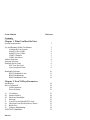
Contents.
Chapter 1. What You Must Do First.
System Requirements.
1
Up And Running Within Ten Minutes.
Configuring Your System.
Setting Up For COM3.
Setting Up For COM4.
COM1-4 Defaults.
COM5 And Above.
Address Selection.
Interrupt Selection.
Multiport Serial Cards.
AST Four Port Card.
Lynx And Quad Cards.
2
3
4
5
5
5
6
7
8
9
9
Handshake Selection.
RS232 Handshake Lines.
RS422 Handshaking
RS485 Handshake Lines.
10
11
13
14
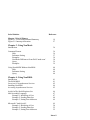
Chapter 2. NewCOM.sys Parameters
Introduction.
Driver Commands.
Valid Parameters.
Driver Defaults.
18
18
18
21
/A I/O Address.
/B Number Buffers.
/H Hardware Handshake.
/I
Interrupt.
/L Lynx 8 Port and Quad RS232 cards.
/O Omit Port From Serial Solution Control.
/S
Buffer Size.
/X Software Handshaking.
XON/XOFF Handshake.
23
24
25
27
29
32
33
34
35
Intro-8
Serial Solution
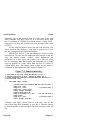
Chapter 2 List Of Figures.
Figure 2-1. NewCOM Command Summary.
Figure 2-2. Interrupt Allocation.
Reference
19
27
Chapter 3. Using NewMode
Introduction.
36
Command Format.
Help.
Parameter Setting.
Examples.
NewMode Differences From DOS ’mode com’.
Query.
Examples.
36
36
37
38
38
39
39
Using NewMODE Without NewBIOS.
Help.
Parameter Setting
Query
40
40
40
40
Chapter 4. Using NewBIOS.
Introduction.
The ROM BIOS.
Overview Of Asynchronous Services.
Installing NewBIOS.
Accessing Asynchronous Services.
41
41
42
44
45
Aside On The 80x86 Registers Set.
8086 Assembly Language.
Example 1, Initialising A Port.
Example 2, Sending Data Out.
Example 3, Setting Port Addresses.
46
47
47
48
49
Microsoft C And QuickC.
Example 1, Initialising A Port.
Example 2, Sending Data Out.
Example 3, Setting Port Addresses.
49
50
52
52
Intro-9
Serial Solution
Reference
Borland Turbo Pascal.
Example 1, Initialising A Port.
Example 2, Sending Data Out.
Example 3, Setting Port Addresses.
53
54
54
55
QuickBASIC V4.5 & Visual Basic Dos.
Example 1, Initialising A Port.
Example 2, Sending Data Out.
Example 3, Setting Port Addresses.
56
57
57
58
GWBASIC/BASICA.
BIOS Interface Setup Routine.
Example 1, Initialising A Port.
Example 2, Sending Data Out.
Example 3, Setting Port Addresses.
59
59
60
62
62
Microsoft FORTRAN77.
Example 1, Initialising A Port.
Example 2, Sending Data Out.
Example 3, Setting Port Addresses.
NewBIOS Default Settings.
63
64
65
66
66
Chapter 5. NewBIOS Reference
Introduction.
Using The Services.
Error Returns.
Summary of services.
Service 0H, Initialise.
Service 1H, Send Character.
Service 2H, Receive Character.
Service 3H, Read Status.
Service 4H, Extended Initialise.
Service 5H, Extended Control.
Service ADH, Set Port Address.
Service AEH, Get Number Ports.
Service AFH, Get/Set IRQ Line.
Service B0H, Get/Set Hardware Handshake.
Intro-10
69
69
70
71
75
78
80
82
84
87
90
92
93
95
Serial Solution
Reference
Service B1H, Get/Set Software Handshake.
Service B2H, Get/Set Card type.
Service B3H, Get/Control buffers.
Service B4H, Get Serial Solution Capability
97
99
103
107
Chapter 5 List Of Figures.
Figure 5-1. NewBIOS Functions Summary.
Figure 5-2. Interrupt Allocation.
71
93
Chapter 6. Terminal Emulators.
Introduction.
Using Terminal Programs.
Setting up.
Running Terminal Programs.
Commands.
Example.
Using Translations.
108
109
109
109
110
113
113
Chapter 7. CTerm
Introduction.
Running Cterm.
Translations.
Get And Put Files.
The CTERM Serial Connection.
Quick Summary.
Opening The File.
Writing To The File.
Fitting The Parts Together.
115
115
116
116
117
117
118
121
125
Chapter 7 List Of Figures.
Figure 7-1. Function open_com().
Figure 7-2. Function uncook().
Figure 7-3. Function inpstr().
Figure 7-4. Function outstr().
Figure 7-5. Function bios_x_init().
Figure 7-6. Function main.
Figure 7-7. Screen Output Examples.
119
120
121
122
123
126
127
Intro-11
Serial Solution
Reference
Chapter 8. Aterm
Introduction.
Running ATERM.
Translations.
The ATERM Serial Connection.
Quick Summary.
Reading From The File.
Writing To The File.
Closing The File.
Serial Port Parameters.
Fitting The Parts Together.
128
128
129
129
129
132
134
135
136
137
Chapter 8 List Of Figures.
Figure 8-1. Subroutine Open-com.
Figure 8-2. Subroutine Uncook.
Figure 8-3. Subroutine Inpstr.
Figure 8-4. Subroutine Outstr.
Figure 8-5. Subroutine Close_com.
Figure 8-6. Subroutine Bios_x_init.
Figure 8-7. Aterm Main Program.
Figure 8-8. Screen Output.
130
132
133
134
135
136
138
140
Chapter 9. PASterm
Introduction.
Running Pasterm.
The Pasterm Serial Connection.
Quick Summary.
Reading From The File.
Writing To The File.
Closing The File.
Serial Port Parameters.
141
141
142
142
145
145
146
147
Chapter 9 List Of Figures.
Figure 9-1. Procedure Open_Com.
Figure 9-2. Procedure InpStr.
Figure 9-3. Procedure OutStr.
Figure 9-4. Procedure Close_Com.
143
145
146
146
Intro-12
Serial Solution
Figure 9-5. Function BIOS_X_Init.
Figure 9-6. Pasterm Main Program.
Figure 9-7. Screen Output Examples.
Reference
147
149
150
Chapter 10. BASterm
Introduction.
Running BASterm.
The BASterm Serial Connection.
Quick Summary.
Reading From The File.
Writing To The File.
Closing The File.
Serial Port Parameters.
Fitting The Parts Together.
152
152
154
154
155
157
157
158
159
Chapter 10 List Of Figures.
Figure 10-1. Open Subroutine.
Figure 10-2. Input Subroutine.
Figure 10-3. Output Subroutine.
Figure 10-4. Closing The File.
Figure 10-5. BIOS Access Subroutines.
Figure 10-6. BASterm Main Program.
155
156
157
157
158
160
Chapter 11. Forterm
Introduction.
Running Forterm.
The Forterm Serial Connection.
Quick Summary.
Opening The File.
Reading From The File.
Writing To The File.
Closing The File.
Serial Port Parameters.
Fitting The Parts Together.
163
163
164
164
164
165
166
167
167
169
Intro-13
Serial Solution
Chapter 11 List Of Figures.
Figure 11-1. Procedure open_com.
Figure 11-2. Function inpstr.
Figure 11-3. Subroutine outstr.
Figure 11-4. Closing The File.
Figure 11-5. Function BIOS_X_init.
Figure 11-6. Forterm Main Program.
Figure 11-7. Screen Output Examples.
Intro-14
Reference
165
166
166
167
168
170
172
What To Do First
Serial Solutions
Chapter 1
What To Do First.
____________
Introduction.
This chapter explains how to get Serial Solutions up and
running as quickly as possible. It starts by showing how install
the software to use the standard COM1 and COM2 serial ports,
then the configuration is adjusted to allow access to COM3 and
COM4. Use of ports COM5 onwards is then explained along
with address setting, interrupt line selection for standard serial
cards followed by the settings for driving multiport serial cards.
Finally the handshaking options that allow RS422 and RS485
cards to be used are dicussed.
The key to trouble free installation is getting the entry
in the CONFIG.SYS file right, time spent reading this
chapter and the chapter on Newcom.sys command line
parameters is well spent.
System Requirements.
___________________
_
1)
2)
3)
Serial Solutions requires the following hardware:An PC compatible computer running DOS.
At least one standard PC serial port.
This serial port can be either on the main system board or
on expansion cards. Up to 32 ports are directly supported.
Standard PC serial ports use 8250, 16450 or 16550
compatible uarts. Any mix of RS232, RS422 or RS485
cards may be used. Multiport cards from a variety of
manufacturers are supported. Note that intelligent serial
port cards, ie those with on board microprocessors are
NOT supported.
Approximately 100 kilobytes of hard disk space is needed
for the minimum installation, 2.0 megabytes is needed if
everything is installed.
Chapter 1
Page 1
Serial Solutions
What To Do First
Up And Running Within Ten Minutes.
_________________________________
This section is intended to get up up and running with
Serial Solutions within ten minutes. A more detailed explanation
of the component parts of the Serial Solution system follows in
later chapters. Since this paragraph is a quick installation, details
for COM3 onwards are not being set, so only COM1 and COM2
can be used for the moment.
Outline
1)
Copy NewCOM.SYS from Disk 1 to the hard disk.
COPY A:NEWCOM.SYS C:\ <return>
2)
Add an entry for the Serial Solution device driver to the
CONFIG.SYS file using an editor such as the MSDOS
editor EDIT.
DEVICE=C:\NEWCOM.SYS
3)
Copy NewMODE.EXE from Disk 1 to the hard disk.
COPY A:NEWMODE.EXE C:\ <return>
4)
Copy EASYC.EXE from the Easy Disk to the hard disk.
COPY A:EASYC.EXE C:\ <return>
5)
Reboot the machine by pressing Ctrl-Alt-Del or by
switching the power off then back on.
The Serial Solutions copyright message is displayed on
power up. The Serial Solution device driver is now ready
for use.
Using COM2.
Assuming that there is a serial port set up as a standard
COM2 port present in the PC, the following uses COM2 as a
terminal. Data entered at the keyboard with be sent to an
attached serial device and any data received will be printed on
the PC screen. The external serial device can be a modem or an
RS232 terminal connected with a suitable cable.
6)
Set the baud rate, parity, stop bits etc to MATCH the
Page 2
Chapter 1
What To Do First
Serial Solutions
serial device connected to the COM2 port.
NEWMODE COM2:9600,N,8,1 <return> or
NEWMODE COM2:1200,E,7,1 <return> etc.
7)
Run the Easyc program using COM2.
EASYC COM2 <return>
Any data type at the keyboard will be sent to the device
attached to the serial port. Incoming data from the serial
port is displayed on screen.
Within the EASY programs the following keys can be
used.
F8 prints the COMDEBUG information on screen
F9 clears the screen
F10 exits back to the DOS prompt.
Serial Solutions Is Up and Running!
Configuring Your System.
______________________
_
The power of Serial Solutions is that many serial ports can
be accessed is a simple, unified way. However, Serial Solutions
has to be told about your system so that it can use the serial
ports that are installed.
For each serial port Serial Solutions has to know the
following three pieces of information:1)
Address. The i/o address of the serial port. ie Where it is
in the system.
2)
Handshake. The kind of flow control that is being used by
the external serial device. The flow control, or
handshaking, ensures that no data is lost by only allowing
data to be sent or received when the devices are able to
accept it.
3)
a)
Interrupt.
Interrupt on Ordinary Serial Port Cards.
The interrupt line used by the serial port. Ideally each
Chapter 1
Page 3
Serial Solutions
What To Do First
serial port will have its own unique interrupt line.
or b) Interrupt On Multiport Cards with Interrupt Sharing.
The interrupt sharing system used if the port is on a
multiport card that is using a shared interrupt mechanism.
Cards with a shared interrupt line typically have a special
register that informs the PC which of its several ports need
servicing.
These parameters are passed to NEWCOM.SYS, the Serial
Solutions device driver, by command line arguments in the
CONFIG.SYS file.
Apart from the standard COM1 and COM2 ports, this
information will have to be given for each COM port used by
Serial Solutions. The Address and the Interrupt are physically
set on the serial card by jumpers or dip switches. The Serial
Solutions address and interrupt must match that actually set on
the card.
Setting Up For COM3.
___________________
_
Assuming that the serial port card has been set by jumpers or
dip switches to the following:COM3 i/o address 03E8 hex using interrupt IRQ 10.
Then the entry in the CONFIG.SYS file would be:device=c:\newcom.sys /A3,3E8 /I3,10
If the external serial device can handle data as fast as we can
send it then we can assume that no handshaking is necessary. So
the entry becomes:device=c:\newcom.sys /A3,3E8 /I3,10 /H3,4
The /A3 parameter means the address of COM3 is being set.
The /I3 parameter means the interrupt used by COM3 is being
set.
The /H3 parameter means the handshake used by COM3 is being
set.
Page 4
Chapter 1
What To Do First
Serial Solutions
Once the PC has been booted with the COM3 parameters in the
CONFIG.SYS file we could now use NEWMODE.EXE and
EASYC.EXE with this port.
NEWMODE COM3:9600,N,8,1 <return>
EASYC COM3 <return>
Setting Up For COM4.
___________________
_
In the same way we could add the configuration for a COM4
port using interrupt line IRQ11. The CONFIG.SYS entry
becomes:device=c:\newcom.sys /A3,3E8 /I3,10 /H3,4 /A4,2E8 /I4,11 /H4,4
COM1-4 Defaults.
________________
Serial Solutions assumes that COM1 is at 3F8hex using interrupt
4 and that COM2 is at 2F8 hex using interrupt 3. This is the
industry standard. COM3 is usually at 03E8hex and COM4 at
02E8hex.
Modern PCs can usually find the COM3 and COM4 port
addresses and indeed often display them on screen as the PC
boots up. In these cases, Serial Solutions will get the COM3 and
COM4 addresses directly from the PC’s BIOS table and
therefore the /A3 and /A4 parameters can be omitted.
However, since there is no fixed standard for the
interrupts for COM3 and COM4 ports the /I3 and /I4
parameters must always be passed on the NEWCOM.SYS
line in the CONFIG.SYS file.
COM5 And Above.
________________
_
There are no industry standards for COM5 and above. This
means that there is no agreed i/o addresses or interrupts for
COM5 or greater. As a result Serial Solutions cannot determine
from the PC’s BIOS, nor can it assume, how these serial ports
have been configured in the PC. Therefor the addresses, interrupt
line and handshake type for COM5 and above have to be made
Chapter 1
Page 5
Serial Solutions
What To Do First
known to the Serial Solutions device driver.
The i/o address, interrupt and handshake used must be
specified in the CONFIG.SYS file on the NEWCOM.SYS entry
line.
Address Selection.
________________
Each serial port has its address set by jumpers or dip
switches on the interface card and occupies 8 i/o consecutive
addresses. As explained in the previous section, com ports
COM1- COM4 are at standard addresses and so do not need to
be explicitly passed to Serial Solutions.
Addresses for COM5 onwards must be passed to the
NEWCOM.SYS driver by the /Ar,add parameter.
Where r specifies the COM ports, r may be a single port or a
range of ports.
And addr is the address in hexadecimal, suffixed with an
optional ’h’ or ’H’. For example:/A5,1A0 COM5 is at 01A0 hex.
/A5,1A0H COM5 is at 01A0 hex.
/A12,200 COM12 is at 0200hex.
When a range of ports is given, addr specifies the address of the
first port in the range, subsequent ports are at 8 byte increments.
For example:/A8-10,1B0 range of ports is COM8 to COM10 starting at
1B0hex
COM8 is at 1B0hex,
COM9 is at 1B8hex,
COM10 is at 1C0hex.
/A13-,300 range is COM13 to max supported starting at 300hex
COM13 is at 300hex,
COM14 is at 308hex,
COM15 is at 310hex,
COM16 is at 310hex.
assuming NewCOM.sys
Always specify the addresses of port COM5 onwards using the
/A command in the CONFIG.SYS file.
Page 6
Chapter 1
What To Do First
Serial Solutions
Interrupt Selection.
_________________
For reliable serial communication each serial port needs its
own interrupt line. In many ways the interrupt is like the bell on
a telephone. When someone is trying to make a call to us our
telephone rings. The bell ringing allows us to stop what we are
doing temporarily, pick up the phone and deal with the person
calling us. After we put the phone down we can carry on where
we previously left off. Imagine what it would be like if
telephones did not have a bell that rang when an incoming call
was received. We would have to constantly pick up the handset
and say "Hello. Anyone there?", just in case we had a caller.
Most of our time would be spent looking for calls that were not
there. Often we would miss incoming calls when we were busy
elsewhere or just forgot to check.
Whenever we attempted to send an outgoing call we would
waste a lot of time waiting for the person on the other end to
pick up the phone and check to see if anyone was there. Most of
the time we would fail to get through and so they would miss
out on vital information we wanted to pass to them.
The interrupt line connected to the serial port allows the
PC to receive data even if the PC is busy doing other things.
The interrupt sets off an alarm in the PC causing it to break off
what it is doing, grab the incoming data, storing it safely for
later, and then continue where it had left off.
If two or more devices are connected to the same interrupt
line then the alarm bell in the PC often does not work correctly.
One device is trying to set the interrupt bell off whilst another
wants it on, the result is unpredictable and data is usually lost.
For reliable serial communication each serial port needs its
own interrupt line. The PC has few only a interrupt lines
available so adding lots of ports can pose problems.
Multiport cards overcome this problem by having special
circuitry on board that prioritises the different ports interrupts
and present a single interrupt to the PC, so using few of the
PC’s precious resources. See below.
Chapter 1
Page 7
Serial Solutions
What To Do First
Interrupt lines for COM3 onwards must be passed to the
NEWCOM.SYS driver by the /In,i parameter.
Where n specifies the COM port, n may only be a single port
NOT a range of ports.
And i is the interrupt line, in the range 2 to 15, used by the
port. If i is -1 then this port does not use interrupts. For
example:/I3,10
COM3 is using interrupt line 10
/I4,11
COM4 is using interrupt line 11
/I5,7
COM5 is using interrupt line 7
/I6,5
COM6 is using interrupt line 5
/I7,12
COM7 is using interrupt line 12
/I2,-1
COM2 is not using interrupts (won’t work well with
Serial Solutions)
Multiport Serial Cards.
____________________
_
Each serial port we have discussed so far has required its
own interrupt line if we want trouble free communications with
external devices. As more serial ports are added a fundamental
limit of the PC expansion bus slot is reached, there are only 11
interrupts lines available. Of the 16 interrupt line in the PC
design only 11 are brought out to the expansion slots, the other
5 are used internally for timers, maths coprocessors etc. The 11
on the slot are reduced to 9 in practice since the floppy disk and
the hard disk require one each. If network, SCSI or sound cards
are added even less interrupts are available.
It soon seems impossible to add an 8 port card to a PC
that already has COM1 and COM2 installed.
To get over the limiting factor of the number of interrupts
available many multiport cards have special circuitry on board
that allows the ports on the card to share a single interrupt
between themselves.
Two interrupt sharing mechanisms have become popular
and both these are supported by Serial Solutions.
Page 8
Chapter 1
What To Do First
Serial Solutions
AST Four Port Card.
__________________
_
The AST Cluster card pioneered a method where a shared
interrupt register holds a status bit for each four serial ports. A
global status bit is set if any of the four ports have an interrupt
pending. This card become popular in the early days of the PC
but its inherent non expandability to more than four ports has
since caused it to fall into great decline.
The presence of multiple cards using the AST type sharing
mechanism, as used on the Flynix and other cards, is passed to
Serial Solutions using the /F parameter on the NEWCOM.SYS
line in the CONFIG.SYS file.
eg /F 5,3,4,5,6
is used to signify that the AST/ Flynix card is using interrupt
line 5, and is sharing it amongst ports COM3, COM4, COM5
and COM6.
Lynx And Quad Cards.
____________________
_
Our Lynx and Quad port cards use the most flexible
approach, based on the original Digiboard mechanism. The
interrupts from the serial ports goes into shared interrupt
circuitry. This presents a single interrupt to the PC, the sharing
circuitry also prioritises and encodes the interrupts. There is a
shared interrupt service register, the SISR, when read it returns a
number between 0 and 255 decimal. If the number read is 255=
0ff hex then no port has an interrupt pending. If the number read
is 0 then serial port 1 on the card has generated an interrupt. If
the number read is 7 then serial port 8 on the card has generated
an interrupt. The interrupts are latched and prioritised so
preventing one port locking out the others. A linking mechanism
allows multiple four and eight port cards in the one PC to be
linked together. Thus giving a theoretical maximum of 255 serial
ports in one PC that use only one interrupt line between them.
In practice 24 or so ports, using buffered FIFO chips, in a fast
PC can provide acceptable performance.
Our Quad and Lynx cards are unique in providing
interrupts 2-7, 10, 11, 12, 14 and 15 both for individual ports
and also for the shared interrupt.
Chapter 1
Page 9
Serial Solutions
What To Do First
The presence of multiple cards using this Lynx card type
sharing mechanism, as used on the Quad RS232 and the Lynx 8
port RS232, as well as the more limited Digiboard cards, is
passed to Serial Solutions using the /L parameter on the
NEWCOM.SYS line in the CONFIG.SYS file.
The syntax is:/L s, i, r
where
s
is the shared interrupt status register address,
i
is the interrupt line shared by the ports
r
may be a list of single ports or a range of ports
For example the following two lines are equivalent:/L 300,15,3,4,5,6,7,8,9,10
/L 300,15,3-10
is used to signify that the Lynx 8 port card has a sisr at
0300hex, using interrupt line 15, shared amongst Com ports
COM3, COM4, COM5, COM6, COM7, COM8, COM9, and
COM10.
For example:/L 3A0,11,5-12
is used to signify that the Lynx 8 port card has a sisr at
03A0hex, using interrupt line 11, shared amongst Com ports
COM5 through to COM12.
Handshake Selection.
__________________
_
The handshake used by a port depends on what wires are
present in the cable used to interconnect the devices and which
pins the wires are joined to at each end of the cable. The cable
is often called a ’cross over’ cable. Both the PC and the external
device have to agree on which handshake method they are using
for communications to run smoothly. If the either side uses
different handshaking methods either no data will be sent or
incoming data will be lost.
In many ways handshaking is similar to the use of traffic
lights on a road, the red light stops the flow of traffic, the green
Page 10
Chapter 1
What To Do First
Serial Solutions
light permits the flow of traffic. Thus a serial port can turn its
output signals on or off to indicate to the external device
whether data can be received or not. It can use its input signals
to sense if the external device is ready to receive more data.
If traffic lights are ignored then crashes will occur. If
handshake lines are ignored data will be sent at the wrong time.
If the traffic lights are misread then no traffic at all might
flow if a green light is misread as a red light. If handshake lines
are misread then serial ports might appear to lock up with no
data flowing in or out.
Serial ports have up to 8 signal lines plus a ground line.
The number of devices connected together using the one stretch
of cable also effects the type of handshake used.
RS232 Handshake Lines.
_____________________
_
RS232 ports, fitted to virtually all PCs as standard, use 8
signal lines. The RS232 standard is ancient in computer industry
terms, introduced in 1962 it is now widely established. It is a
slow speed, short distance, single ended transmission system (ie
only one wire per signal). Typically RS232 maximum cable
length is 50 feet with a maximum data rate of 20K bits per
second. RS232 is for data transmitted between only one device
and one other.
The original PC’s RS232 port was a 25 way D type connector
but now PC’s usually have a 9pin D type connector.
Chapter 1
Page 11
Serial Solutions
RS232 signal lines.
TXD, Transmitted data an output from PC
RXD, Received data an input to PC
RTS, Request To Send an output from PC
CTS, Clear To Send an input to PC
DSR, Data Set Ready an input to PC
DCD, Data Carrier Detect an input to PC
DTR, Data Terminal Ready an output from PC
RI, Ring Indicator an input to PC.
What To Do First
Data line.
Data line.
Handshake line.
Handshake line.
Used by Modems.
In some RS232 systems the handshake lines are not used or are
simply ignored. Only the transmitted data line, received data line
and the ground pins need be connected. This method, often
called ’the 3 wire handshake’, works well only if small amounts
of data are sent or if both devices are fast enough to deal with
any amount of data received. The ’3 wire handshake’ assumes
that all the traffic lights are always green and that data can be
sent at any time.
Every example in this chapter so far has used the ’3 wire
handshake’, so that the PC always believes it can send data. This
was specified just to get the data transfer going. The ’3 wire
handshake’ was specified in the NEWCOM.SYS driver by the
/Hr,4 parameter. Where r specifies the COM ports, r may be a
single port or a range of ports. For example:/H1,4
sets up no handshaking for COM1.
/H12,4
sets up no handshaking for COM12.
/H7-16,4 sets up no handshaking for COM7 to COM16.
Page 12
Chapter 1
What To Do First
Serial Solutions
A common RS232 handshake is the DTR /CTS handshake.
Here the traffic light signal is passed out of the PC to the
external device on its DTR wire. The traffic light signal from
the external device is brought in on the PC’s CTS wire.
The PC will only transmit, ie send, data when the CTS
input is green, ie logically true. The PC will stop transmitting
data when the CTS input is red, ie logically false.
When the PC is able to receive data it will set the DTR
output green, ie logically true. When it cannot accept any data it
will set the DTR output red, ie logically false.
The RS232 DTR/CTS handshake is was passed to the
NEWCOM.SYS driver by the /Hr,0 parameter. Where r specifies
the COM ports, r may be a single port or a range of ports. For
example:/H1,0
sets up DTR/CTS handshaking for COM1.
/H12,0
sets up DTR/CTS handshaking for COM12.
/H7-16,0 sets up DTR/CTS handshaking for COM7 to COM16.
RS422 Handshaking
_________________
_
RS422 interfaces have less signals than RS232 serial ports,
but to reduce noise, while allowing high speeds and long
distance transmission, each signal is carried by two wires as a
twisted pair, and is thus a differential data transmission system.
Over distances up to 40 feet the maximum data rate is 10
Megabits per second, and for distances up to 4000 feet the
maximum data rate is 100 Kilobytes per second, allowing
communication much further and faster than RS232. Like
RS232, RS422 is usually used for data transmitted between only
one device and one other, but up to 10 devices can
simultaneously receive the transmitted data.
RS422 signal lines.
TXD, Transmitted data an output from PC
RXD, Received data an input to PC
RTS, Request To Send an output from PC
CTS, Clear To Send an input to PC.
Chapter 1
Data line.
Data line.
Handshake line.
Handshake line.
Page 13
Serial Solutions
What To Do First
RS422 ports only have a transmitted data line pair, a
received data line pair, request to send output line pair and clear
to send input line pair.
Therefore the usual RS422 handshake is the RTS /CTS
handshake. Here the traffic light signal is passed out of the PC
to the external device on its RTS wire. The traffic light signal
from the external device is brought in on the PC’s CTS wire.
The PC will only transmit, ie send, data when the CTS
input is green, ie logically true. The PC will stop transmitting
data when the CTS input is red, ie logically false.
When the PC is able to receive data it will set the RTS
output green, ie logically true. When it cannot accept any data it
will set the RTS output red, ie logically false.
The RS422 RTS/CTS handshake is was passed to the
NEWCOM.SYS driver by the /Hr,1 parameter. Where r specifies
the COM ports, r may be a single port or a range of ports. For
example:/H1,1
sets up RTS/CTS handshaking for COM1.
/H12,1
sets up RTS/CTS handshaking for COM12.
/H7-16,1 sets up RTS/CTS handshaking for COM7 to COM16.
RS485 Handshake Lines.
_____________________
_
The RS485 interface is based in the RS422 standard but
have only one or two signals. As in RS422, to reduce noise
while allowing high speeds and long distance transmission each
signal is carried by two wires as a twisted pair, and is thus a
Page 14
Chapter 1
What To Do First
Serial Solutions
differential data transmission system. Over distances up to 40
feet the maximum data rate is 10 Megabits per second, and for
distances up to 4000 feet the maximum data rate is 100
Kilobytes per second, allowing communication much further and
faster than RS232. RS485 allows up to 32 transmitter receiver
pairs to be present on the line at one time. If more than one
device may transmit data, the PC’s RTS line is used as as
transmit enable signal, so preventing contention between talkers.
RS485 signal lines.
TXD, Transmitted data an output from PC
RXD, Received data an input to PC.
Data line.
Data line.
RS485 ports only have a transmitted data line pair, a
received data line pair. Frequently, to save having too many
wires, the RS485 system shares the transmitted and received data
lines.
The RS485 bus is implemented in one of three ways and
the handshaking option is set accordingly. These three RS485
implementations are listen only devices, party line half duplex
and party line full duplex.
RS485: PC To Listen Only Devices.
One cable.
The RS485 listen only device handshake connects one PC
to one or mode devices using only ONE twisted pair cable. The
transmit lines of the PC are connected to the receive inputs of
the devices. The external RS485 devices can only listen to data
received from the PC and do not ever reply back to the PC. The
PC need only ever transmit data. It does not receive any data.
Thus the RS485 card is in transmit only mode, this is handshake
Chapter 1
Page 15
Serial Solutions
What To Do First
type 3. The RS485 transmit only handshake is passed to the
NEWCOM.SYS driver by the /Hr,3 parameter. Where r is the
COM port number, r may be a single port or a range of ports.
For example:/H1,3
sets up 485 transmit only handshaking for COM1.
/H12,3
sets up 485 transmit only handshake for COM12.
/H7-16,3 sets 485 transmit only handshake for COM7 to
COM16.
RS485: Party Line Half Duplex.
One cable.
The RS485 party line, half duplex handshake connects one
PC to one or mode devices using only ONE twisted pair cable.
The devices, including the PC, take turns to transmit data along
the cable, all can receive the data transmitted. The PC usually is
the master controlling the other devices. Each device has its own
address and only transmits data when the master commands it to
do so. When the PC is not actually in the process of transmitting
data, it removes its own transmitters from the bus so allowing
the devices to transmit their information down the common
twisted pair.
The RS485 party line, half duplex handshake is was passed
to the NEWCOM.SYS driver by the /Hr,2 parameter. Where r is
the COM port number, r may be a single port or a range of
ports. For example:/H1,2
sets up 485 half duplex handshaking for COM1.
/H12,2
sets up 485 half duplex handshaking for COM12.
/H7-16,2 sets 485 half duplex handshaking for COM7 to
COM16.
RS485: Party Line Full Duplex.
Two cables.
The party line full duplex connects a PC to one or more
devices using two twisted pair cable. The transmit of the PC
goes to the receive input of all the devices, the transmit of the
devices is joined together and goes to the receive input of the
PC. The PC can transmit data whenever it wishes, even when
the devices are transmitting data. The devices take turns to
transmit data along the cable. The PC is the master controlling
the other devices. Each device has its own address and only
Page 16
Chapter 1
What To Do First
Serial Solutions
transmits data when the master commands it to do so.
The RS485 full duplex handshake, from a software point
of view, is identical to the 3 wire no handshaking option and so
is passed to the NEWCOM.SYS driver by the /Hr,4 parameter.
Where r is the COM port number, r may be a single port or a
range of ports. For example:/H1,4
sets up no handshaking (485 full duplex) for COM1.
/H12,4
sets up no handshaking (485 full duplex) for COM12.
/H7-16,4 sets no h/shake (485 full duplex) for COM7 to
COM16.
Chapter 1
Page 17
Serial Solutions
Newcom Parameters
Chapter 2
NewCOM.SYS
Config.sys Line
Parameters.
____________
Introduction.
This chapter explains the command line parameters used in
the CONFIG.SYS file to configure the Serial Solutions device
driver NewCOM.sys.
The key to a successful installation is to get the parameter
switches right.
Driver Commands.
________________
_
To install NewCOM a line of the following form must be
placed in the machine’s CONFIG.SYS file:
device=newcom.sys[/<switch>][/<switch>].....
This section gives details of the command switches, which are
used to control the device driver.
Each switch begins with a ’/’, and has one or more
parameters separated by commas. Spaces can be placed
anywhere, except in the middle a number. Letters can be either
upper or lower case in any mix, so ’/B5’ and ’/b5’ are
equivalent. The switches can be placed in any order on the line,
and if switches which contradict each other are placed on the
line the rightmost switch takes precedence.
Generally the various options default to reasonable valuesmany users will not need to set any options.
Valid Parameters.
_______________
_
The command line switches take none, one or more
parameters. The separator between commands and successive
parameters is either a space or a comma. The parameters fall
Page 18
Chapter 2
Newcom Parameters
Serial Solutions
into the following types, note the port range <range> is of
particular interest.
The maximum number of serial ports supported by the
driver is known as maxport. Different version of the driver
support different numbers of ports.
NewCOM.sys supports 16 serial ports so maxport is 16, when
NewCOM.sys is being used.
NewCOM24.sys supports 24 serial ports so maxport is 24, when
NewCOM24.sys is being used.
NewCOM32.sys supports 32 serial ports so maxport is 32, when
NewCOM32.sys is being used.
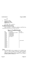
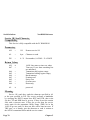
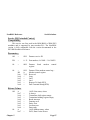
Figure 2-1. NewCOM Command Summary.
_____________________________________
_
Function
Address of port
Buffer size
Flynix setup
Handshake
Interrupt line
Lynx card setup
Omit port
Size of buffers
Xon-Xoff
Command Line Switch
/A range, hexaddr
/B buffs
/F irq1, p1, p2, p3, p4, irq2,p5, p6, p7, p8
/H [range], [hs]
/I port, irq
/L hexaddr, irq, range[,range][, range]
/O range [, range][, range]
/S memsize
/X range[, xon, xoff]
<port>
A decimal number in the range 1 to maxport specifying a
COM port. eg 1 means COM1 10 means COM10.
<range>
A list of none, one or more ports. The each port is a
decimal number in the range 1 to maxport. The range can
be a singe decimal number, eg 5; a single decimal number
and a dash eg -5; a dash and single decimal number, eg 5or two decimal numbers separated by a dash eg 5-7.
Here are several examples of valid ranges. (using the
Chapter 2
Page 19
Serial Solutions
Newcom Parameters
Handshake switch).
/H5,4
Serial port COM5 only uses handshake type 4.
/H5-7,4
Serial ports COM5, COM6 and COM7 all use
handshake type 4.
/H5-,4
Serial ports COM5, 6, 7 all the way to maxport
-the maximum supported by the driver, eg
COM16 use handshake type 4.
/H-5,4
Serial ports COM1, COM2, COM3, COM4 and
COM5 all use handshake type 4.
<range> [, range]
A list of one or more ranges of ports. Commands for
setting up the shared interrupt multiport cards have to
define numerous serial ports and so accept a series of
ranges.
5-8,10-12,14Serial ports COM5 to COM8 and COM10 to
COM12 and COM14 to the maximum
supported by the driver.
-4,7,9-11 Serial ports COM1 to COM4, COM7 and
COM9 to COM11
<irq>
A decimal number in the range 2-15, specifying a PC bus
interrupt line.
/I3,10
Serial port COM3 is using interrupt 10.
/I4,11
Serial port COM4 is using interrupt 11.
<hs> One decimal number in the range 0-4 used to specify
which software flow control method is in use.
<hexaddr>
An hexadecimal word in the range 0000h-0FFFFh, this is
used to specify the i/o address of a serial port. The word
must start with a number 0-9 or a-f. The address may have
an optional ’h’ or ’H’ suffice.
/A1,03F8 Serial port COM1 at address 03f8 hex.
/A2,2f8
Serial port COM2 at address 02f8 hex.
Page 20
Chapter 2
Newcom Parameters
Serial Solutions
/A5,1B0h Serial port COM5 at address 01b0 hex.
<memsize>
A decimal number in the range 2-32768, rounded down to
the nearest power of 2. Used to set the size of the interrupt
driven i/o buffer.
<buffs>
Decimal number in the range 1 - maxport. Used to specify
the number of buffers to allocate. Each interrupt driven
port needs its own buffer so this also sets the maximum
number of ports that can be used in interrupt mode.
Driver Defaults.
______________
When no switches are specified in the config.sys file the
following defaults are used:
I/O Addresses.
Only those ports found by the power on ROM BIOS check
are set up automatically.
On all PC compatibles the ROM BIOS checks for COM1
and COM2 at their usual I/O addresses, 03F8H and 02F8H
respectively so these ports are automatically recognised.
On most modern machines the ROM BIOS also checks for
COM3 at 03E8H and COM4 at 02E8H.
IBM PS/2 machines with the micro channel bus have
COM3 at 3220 and COM4 at 3228.
Interrupt Lines.
COM1
4
COM2
3
COM3-1 (meaning none set)
Multiport Cards.
No multiport cards are assumed to be present.
Hardware Handshake.
All ports default to H4, the 3 wire No Handshake, that is
ports are always ready to send and receive data.
Chapter 2
Page 21
Serial Solutions
Newcom Parameters
Software Handshake.
XON/XOFF handshaking is disabled, XON is 17, XOFF is
19, should software handshaking be turned on.
Buffer Size.
Buffers are 256 bytes long.
Buffer Number.
The maximum number of pairs of buffers is 6 (that is up
to six ports can use interrupt driven buffered i/o).
Baud rate etc.
All ports recognised by the ROM BIOS are reset to 2400
Baud, no parity, 8 data bits and one stop bit when the
machine is powered up.
All ports whose address is set in the config.sys file are
also set to 2400 baud, no parity, 8 data bits and 1 stop bit.
The other ports, not recognised by Serial Solutions at boot
time, are reset by the PC’s hardware at power up to no
parity, 5 data bits and one stop bit.
Buffer enabling.
When the machine is rebooted the buffers for all ports
whose address has been found by the BIOS or set in the
config.sys file are allocated. This is up to the limit set by
the /B command.
Page 22
Chapter 2
Newcom Parameters
Serial Solutions
I/O Address.
Switch:
/A range,hexaddr
Purpose:
Set the I/O address of serial port COMn.
’range’
’range’ must be given. Range specifies the COM ports,
range may be a SINGLE port OR a RANGE of ports.
’hexaddr’
is the address of the port, it must be in hexadecimal,
suffixed with an optional ’h’ or ’H’.
Single port examples:- (old method:- still works)
/A5,1A0 COM5 is at 01A0 hex.
/A5,1A0H COM5 is at 01A0 hex.
/A12,200 COM12 is at 0200hex.
When a range of ports is given, hexaddr specifies the address of
the first port in the range, subsequent ports are at 8 byte
increments. Range port examples:- (new method:- less typing,
easy to understand)
/A8-A10,1B0
port range is COM8 to COM10 starting at 1B0 hex
COM8 is at 1B0hex,
COM9 is at 1B8hex,
COM10 is at 1C0hex.
/A13-,300 range is COM13 to maxport, starting at 300hex
COM13 is at 300hex,
COM14 is at 308hex,
COM15 is at 310hex,
COM16 is at 310hex. assuming NewCOM.sys
NEWCOM.SYS supports up to 16 COM ports.
NEWCOM24.SYS supports up to 24 COM ports.
NEWCOM32.SYS supports up to 32 COM ports.
Chapter 2
Page 23
Serial Solutions
Newcom Parameters
Number Buffers.
Switch:
/B buffs
Purpose:
Set number of pairs of buffers to be allocated.
buffs
is a decimal number in the range 1-maxport and is the
number of buffers to allocate. Each interrupt driven port
needs its own buffer so this also sets the maximum number
of ports that can be used in interrupt mode.
Always ensure that there is one for each port in use.
NewCOM reserves space for the buffers from main memory
when the machine is booted. Each port whose address is known
at boot time either by the being recognised by the ROM BIOS
or whose address is set in the config.sys file have a buffer
allocated to them when NewCOM.sys loads, provided sufficient
are defined using the /B command.
For example
/B 9 reserves 9 buffers, one for the built in COM1 port and one
each for the 8 ports on the Lynx card.
For example
/B 4 reserves space for four pairs of buffers, enough for four
serial ports.
The default is six pairs. The buffer allocated contains an equal
amount of room for both the incoming data and the out going
data.
Page 24
Chapter 2
Newcom Parameters
Serial Solutions
Hardware Handshake.
Switch:
/H [range],[hs]
Purpose:
Select which hardware handshake type to use on the
specified ports. Hardware handshake is flow control of data
determined by the state of various lines in the port
connector. See chapter "What To Do First", section
"Handshake Selection" for more information.
’range’
specifies the COM port. Range may be a SINGLE port OR
a RANGE of ports. If range is not specified the handshake
is applied to all serial ports.
’hs’ is a number indicating the type of handshake, and 4 is the
default. This does not
___ override a previous XON/XOFF
setting, in conjunction with which it may be used. The
types are listed below.
The hardware handshake currently supported are:
Type 0
RS232 DTR/CTS
The PC only transmits when CTS is input true. When
the PC is able to receive its sets DTR output true.
The DSR and DCD inputs are ignored. The RTS
output line is set true just in case the external serial
device needs a true signal.
Type 1
RS422 RTS/CTS
The PC only transmits when CTS is input true. When
the PC is able to receive its sets RTS output true.
The DSR and DCD inputs are ignored. The DTR
output line is set true just in case the external serial
device needs a true signal.
Type 2
RS485 Half duplex
Before any data is sent the PC sets RTS true, after
the last byte in the buffer has been sent the PC sets
RTS false. RTS is used as a transmit gating control.
The CTS, DSR and DCD inputs are ignored. The
DTR output line is set true just in case the external
Chapter 2
Page 25
Serial Solutions
Type 3
Type 4
Newcom Parameters
serial device needs a true signal.
RS485 Send only.
This is a half duplex, transmit only handshake.
The PC transmits whenever it wishes, it cannot
receive any data.
The CTS, DSR and DCD inputs are ignored. The
RTS output line is set true just in case the external
serial device needs a true signal.
3 Wire Handshake.
Really no handshake at all since the PC transmits
irrespective of the handshake lines.
The 3 wires are TxD, RxD and Ground, no other
lines are required. Thus the CTS, DSR and DCD
inputs are ignored. The RTS and DTR output lines
are set true just in case the external serial device
needs a true signal.
Single port examples:/H1,2
Set COM1, handshake 2
/H,1
Set handshake 1 for all ports
The /H switches are processed from left to right, so for example
/H,2 /H1,0 /H2,1
would set COM3 to COM16 to handshake type 2,
COM1 to type 0 and COM2 to type 1.
When a range of ports is given, every port port in the range is
set to the specified handshake value.
Range of port examples:/H7-16,4 sets up handshake type 4 =no handshake for COM7
to COM16.
/H3-5,2
sets up handshake type 2 CTS/RTS for port COM3,
COM 4 and COM5.
Page 26
Chapter 2
Newcom Parameters
Serial Solutions
Hardware Interrupt.
Switch:
/I port, irq
Purpose:
Set interrupt line is use with the COM port. With the
exception of specially designed shared interrupt cards like
the Lynx & Quad RS232 cards, for reliable communications each port needs its own interrupt line.
’port’
a decimal number in the range 1 to maxport specifying a
COM port. eg 1 means COM1 10 means COM10. If port
is not specified the interrupt line is applied to all ports.
’irq’ is the interrupt line in the range 2 to 15, or, to indicate no
interrupt line, -1 or nothing.
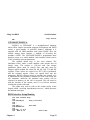
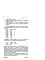
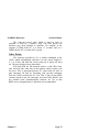
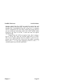
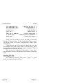
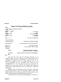
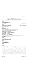
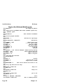
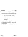
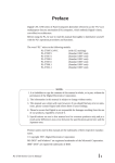
Figure 2-2. Interrupt Allocation.
____________________________
ÚÄÄÄÄÄÂÄÄÄÄÄÄÄÄÄÄÄÄÄÄÄÄÄÄÂÄÄÄÄÄÄÄÄÄÄÄÄÄÄÄÄÄÄÄÄÄÄÄÄÄÄÄÄÄÂÄÄÄÄÄÄÄÄÄÄÄÄ¿
³ýSTATUS ³
³ IRQ ³ýNORMAL USE ýý³ýCOMMENTS
ÃÄÄÄÄÄÅÄÄÄÄÄÄÄÄÄÄÄÄÄÄÄÄÄÄÅÄÄÄÄÄÄÄÄÄÄÄÄÄÄÄÄÄÄÄÄÄÄÄÄÄÄÄÄÄÅÄÄÄÄÄÄÄÄÄÄÄÄ´
³ý2ýýý³ýVGA GRAPHICS CARD³ýUsed by very few VGA cards ý³ Usually OK ³
ý ýýýý³ý
ý³
³
³ý ýýý³ý
³ýDedicated to COM2 at 2F8hexý³ COM 2 ONLY ³
³ý3ýýý³ýCOM2
ý ýýýý³ý
ý³
³
³ý ýýý³ý
³ýDedicated to COM1 at 3F8hexý³ COM 1 ONLY ³
³ý4ýýý³ýCOM1
ý ýýýý³ý
ý³
³
³ý ýýý³ý
³ýDOS/WIN don’t use this IRQ ý³ Good in DOS³
³ý5ýýý³ýLPT 2
ý ýýýý³ýAvoid with OS/2 Novell WinNT³ & Windows ³
³ý ýýý³ý
ý ýýýý³ý
ý³
³
³ýýý ý³ý
³ý6ýýý³ýFLOPPY DISK ³ýDedicated to Floppy Disk ý³ AVOID !!! ³
ý ýýýý³ý
ý³
³
³ý ýýý³ý
³ýDOS/WIN don’t use this IRQ ý³ Good in DOS³
³ý7ýýý³ýLPT 1
³ý ýýý³ýSoundblaster ýýýý³ýAvoid with OS/2 Novell WinNT³ & Windows ³
ý ýýýý³ý
ý³
³
³ýýý ý³ý
ý³ GOOD
³
³ý10ýý³ýUsually Free ³ýRecommended for COM3
ý ýýýý³ý
ý³
³
³ý ýýý³ý
ý³ GOOD
³
³ý11ýý³ýUsually Free ³ýRecommended for COM4
³
³ý ýýý³ýAdaptec SCSI ýýýý³ýif not Adaptec SCSI card ý³
ý ýýýý³ý
ý³
³
³ý ýýý³ý
³ý12ýý³ýPOINTING DEVICE ³ýFree if Mouse is on COM port³ Usually OK ³
ý ýýýý³ý
ý³
³
³ý ýýý³ý
³ Usually BAD³
³ý14ýý³ýIDE HARD DISK ³ýUsually In Use.
ý ýýýý³ýFree when SCSI disks in useý³
³
³ý ýýý³ý
ý ýýýý³ý
ý³
³
³ý ýýý³ý
³ GOOD
³
³ý15ýý³ýUsually Free ³ýRecommended
ÀÄÄÄÄÄÁÄÄÄÄÄÄÄÄÄÄÄÄÄÄÄÄÄÄÄÄÄÄÄÄÄÄÄÄÄÄÄÄÄÄÄÄÄÄÄÄÄÄÄÄÄÄÄÄÁÄÄÄÄÄÄÄÄÄÄÄÄÙ
Chapter 2
Page 27
Serial Solutions
Newcom Parameters
A serial port must be assigned an interrupt line before it
can be used. On ISA bus PC compatibles machines and EISA
bus machines only one serial port can use an interrupt line. On
PS/2 machines serial ports can share interrupts. Multiport cards
with special interrupt hardware have different rules- see the /L
command switch (also /F) for setting up those cards.
Each serial port needs its own interrupt line for trouble
free performance, if two serial ports are allocated the same IRQ
line only one can use it at any time. NewCOM allows one port
to use the IRQ line, and any others allocated that line are polled.
For DOS and Windows 3.x use, after COM1 and COM2
installed, then IRQs 5, 7, 10, 11, 12 and 15 are available.
For example
/I1,4
set COM1 to use irq line 4
/i,-1
sets all ports to no interrupt
/i2,
sets COM2 to no interrupt
/I1,4
set COM1 to use irq line 4
/I3,10
set COM3 to use irq line 10
/I4,11
set COM4 to use irq line 11
/I5,12
set COM5 to use irq line 12
/I6,15
set COM6 to use irq line 15
Page 28
Chapter 2
Newcom Parameters
Serial Solutions
Lynx 8 Port and Quad RS232 cards.
Switch:
/L hexaddr, irq, range [, range] [, range]
The shorthand allowed in using port ranges with the Lynx
command, as well as the port Address and Handshake
commands, allow a multiport system to be setup by only a few
short entries in the NewCOM.SYS line in the CONFIG.SYS file.
The older notation, without ranges, where every port is
explicitly defined can still be used but is more cumbersome.
Switch:
/L hexaddr, irq, p1, p2, p3, p4, p5, p6, p7, p8...
Purpose:
Set up one or more Lynx 8 port or Quad port serial cards.
The /L command has superceeded the /D command.
’hexaddr’
is address of the SISR, Shared Interrupt Status Register.
’irq’ is the interrupt line set on the Shared IRQ jumper block.
’range’
specifies the COM port. Range may be a SINGLE port OR
a RANGE of ports. Each port is a decimal number
between 1 and maxport. Multiple ranges may be specified,
if necessary, to define all the ports in use.
Range port examples:-
(new method:- less typing, easy to
understand)
/L 03A0, 12, 3-10
Lynx card with Shared Interrupt Status Register, SISR, at
i/o address 03A0 hex, Interrupt 12 is the shared interrupt,
Lynx port#1 is mapped as COM3
Lynx port#2 is mapped as COM4
Lynx port#3 is mapped as COM5
Lynx port#4 is mapped as COM6
Lynx port#5 is mapped as COM7
Lynx port#6 is mapped as COM8
Lynx port#7 is mapped as COM9
Lynx port#8 is mapped as COM10
Chapter 2
Page 29
Serial Solutions
Newcom Parameters
Note: Ports on a Lynx or Quad port card that are using interrupt
sharing MUST be configured with the /L command line switch
rather than the /I switch. Ports on a Lynx or Quad card that are
not using the shared interrupt but have their own separate
interrupt must be configured with the /I command switch.
’p1’, ’p2, etc.
Older notation.
p1 etc are the COM port allocated to each serial port on
the Lynx card. For example if p1 is ’3’, then port 1 on the
card will be accessed as COM3. The COM3 i/o address, ie
the address of the Lynx card port#1, is specified elsewhere
on the CONFIG.SYS file line, using the /A3 switch. The
’p’ places can be empty, indicating those ports on the card
that are not being set up to use the shared interrupt
mechanism.
Defining the ports using 8 separate port numbers is now
equivalent to using 8 single port ’ranges’.
Older notation example:/L 300,7,3,4,5,6
Quad port card.
/L 300,7,3-6
Equivalent new notation.
Quad card with Shared Interrupt Status Register at 0300H,
sharing interrupt 7, Quad port#1 is COM3,
Quad port#2 is COM4,
Quad port#2 is COM5,
Quad port#2 is COM6.
Older notation example:/L 03A0,3,2,3,4,5,6,7,8,9
Lynx 8 port card.
/L 03A0,3,2-9
Equivalent new notation.
Lynx card with Shared Interrupt Status Register, SISR, at
i/o address 03A0 hex, interrupt 3 is the shared interrupt,
Lynx port#1 is mapped as COM2
Lynx port#2 is mapped as COM3
Lynx port#3 is mapped as COM4
Lynx port#4 is mapped as COM5
Lynx port#5 is mapped as COM6
Page 30
Chapter 2
Newcom Parameters
Serial Solutions
Lynx port#6 is mapped as COM7
Lynx port#7 is mapped as COM8
Lynx port#8 is mapped as COM9
If more than one Lynx card is installed in the machine
then these can be linked together as shown in the cards’
installation manual, in which case they would share the SISR,
shared interrupt status register and interrupt line of the first card.
Install this combination as a single card, with one /L switch.
Older notation example
/L 03A0,3,2,3,4,5,6,7,8,9,10,11,12,13
’12’ port card.
/L 03A0,3,2-12
Equivalent new notation.
Lynx card with Shared Interrupt Status Register, SISR, at
i/o address 03A0 hex, Interrupt 3 is the shared interrupt,
Lynx card 1 port#1 is mapped as COM2
Lynx card 1 port#2 is mapped as COM3
Lynx card 1 port#3 is mapped as COM4
Lynx card 1 port#4 is mapped as COM5
Lynx card 1 port#5 is mapped as COM6
Lynx card 1 port#6 is mapped as COM7
Lynx card 1 port#7 is mapped as COM8
Lynx card 1 port#8 is mapped as COM9
Lynx card 2 port#1 is mapped as COM10
Lynx card 2 port#2 is mapped as COM11
Lynx card 2 port#3 is mapped as COM12
Lynx card 2 port#4 is mapped as COM13
Alternatively, the cards can be installed separately, each
card using its own status registers and interrupts. Note that
although linked cards can share interrupts, separate cards cannot
share any interrupt line.
Older notation example
/L 03A0,3,2,3,4,5,6,7,8,9
/L 0300,7,10,11,12,13,14,15,16,17
/L 03A0,3,2-9
/L 0300,7,10-17
Chapter 2
Two 8 port card.
1st card SISR at 03A0
2nd card SISR at 0300
Equiv new notation 1st card.
Equiv new notation 2nd card.
Page 31
Serial Solutions
Newcom Parameters
Omit Port From Serial Solution Control.
Switch:
/O range
Purpose:
Prevents Serial Solutions from managing that port. If you
wish a mouse driver or the default DOS handlers to control a
serial port then remove that port from serial solutions control.
’range’
’range’ must be given. Range specifies the COM ports,
range may be a SINGLE port OR a RANGE of ports.
Single port examples:- (old method:- still works)
/O1 COM1 not under Serial Solutions control.
/O2 COM1 not under Serial Solutions control.
Range port examples:/O8-10
Ports COM8 to COM10 outside Serial Solutions control.
/O13- range is COM13 to maxport (=16 with NewCOM.sys).
COM13 to COM16 not under Serial Solutions control.
Page 32
Chapter 2
Newcom Parameters
Serial Solutions
Buffer Size.
Switch:
/S memsize
Purpose:
Set size of all buffers in bytes, memsize is rounded to the
nearest power of 2, and must be a decimal number in the range
32 to 32768. For any serial port opened two buffers of size
memsize are allocated, one for input and the other for output.
The space for the buffers is reserved by the driver when the
machine is booted, and, provided an address has been set for the
port either by being recognised by the ROM BIOS or by having
its address set in the config.sys file the buffer is allocated to the
port when NewCOM.sys loads.
The NUMBER of buffers, of size memsize, allocated is set by
the /B command switch.
Example:/S 512
sets the buffer size to 512 bytes. The default size is
256 bytes.
Note that in actual operation only memsize-1 bytes are
available, so the default buffer, nominally 256 bytes long, can
only hold 255 bytes.
Chapter 2
Page 33
Serial Solutions
Newcom Parameters
Xon-Xoff Handshaking.
Switch:
/X [range] [,xon,xoff]
Purpose:
Set port COMn to XON/XOFF handshaking. In this mode
the hardware handshake lines are ignored and the characters
XON and XOFF are used to control the flow of characters on
the serial line.
’range’
specifies the COM port. Range may be a SINGLE port OR
a RANGE of ports. If range is not specified the
XON/XOFF handshake is applied to all serial ports.
’xon, xoff’
The optional parameters XON and XOFF are decimal
numbers which are to be used as the XON and XOFF
characters. Their default values are 17 (DC1) and 19
(DC3) respectively.
Single port example:
/X2
XON/XOFF handshake used by COM2
/X3,18,20 XON/XOFF handshake used by COM3
Data flow started by char code 18 and stopped by
char code 20.
If the port range is not given, then XON/XOFF handshaking and
any specified handshake characters are set for all ports, as
/X
XON/XOFF handshake used by all ports.
/X,18,20 XON/XOFF handshake used by all ports.
Data flow started by char code 18 and stopped by
char code 20.
When a range of ports is given the XON/XOFF handshake
applies to all the ports within the specified range.
Range port examples:- (new method:- less typing, easy to
understand)
/X-4
XON/XOFF handshake used by COM1 to COM4.
/X8-10
XON/XOFF handshake used by COM8 to COM10.
/X13XON/XOFF handshake used by COM13 to maxport.
eg NEWCOM.SYS supports up to 16 COM ports.
Page 34
Chapter 2
Newcom Parameters
Serial Solutions
XON/XOFF Handshake.
_____________________
_
In the XON/XOFF handshake two characters are assigned
a special meaning by the serial port. One, called XON, is sent
by a device to signal that it is ready to receive data. The second,
called XOFF, is sent when the device can no longer receive
data. NewCOM therefore traps XON and XOFF characters as
they arrive and uses them to switch on and off the output of
characters. The user will not detect these characters. Interrupt
driven input sends an XOFF when the input buffer is nearly full,
and an XON when the buffer is emptied to restart the remote
device transmitting. Interrupt output is halted when an XOFF is
received, and restarted when an XON is received.
________
Beware!
The driver does not check the data sent to it by the user
for XONs or XOFFs, which means that they are sent over the
serial line. The remote device will interpret these as XON and
XOFF, forcing it to stop and start transmissions. Likewise if the
user tries to send data which contains XONs and XOFFs to the
PC it will interpret them as such. This will not be a problem
with text data, which generally does not use the usual XON and
XOFF characters. Binary data could though be a problem, so
look out for the symptoms-data lost as buffers overflow, and odd
bytes lost because their values were the same as XON and
XOFF.
Chapter 2
Page 35
Serial Solutions
Using NewMode
Chapter 3
Using NewMODE.
____________
Introduction.
NewMODE is a replacement for the DOS ’mode com...’
command which supports some of the extra features available
under NewBIOS and NewCOM. It enables the user to set the
baud rate parity, word length and number of stop bits of a serial
port, and a query mode allows the user to find the settings of
one or all ports. The i/o address and interrupt line can also be
set with the newmode command.
Command Format._
________________
In the descriptions which follow a string of characters
enclosed in angled braces <thus> indicates a symbol which
should be replaced by a string defined later. Optional parameters
are enclosed in square braces [to indicate that they don’t
necessarily have to be included]. Alternatives are enclosed in
curly braces and separated by vertical bars as {one|or
another|but not both}. Note that spaces are important, for
example the line
c>newmode com1:1200 ,e,7,1
which is a legal syntax for the DOS mode command, will
prevent further use of COM1. Use only the spaces shown in the
syntax, and check them against the examples if you’re still not
sure.
NewMODE can be used in three main ways: help,
parameter setting (like the DOS mode com command) and query.
_____
Help.
To obtain help on the NewMODE command type:
c>newmode
This returns a brief description of the command syntax.
Page 36
Chapter 3
Using NewMODE
Serial Solutions
Parameter Setting._
________________
This mode nearly mimics the DOS ’mode com’ command,
and allows the user to set the parameters (for example baud rate,
parity) of a port.
The command takes several parameters, firstly the port,
then a group of parameters defining the baud rate, parity,
number of data bits (word length) and the number of stop bits
(these separated by commas), then an optional i/o address and an
irq line number separated by spaces.
Note: The ability to set the i/o address and irq numbers
using NewMODE is for backwards compatibility with
previous versions of Serial Solutions. From version 2.00
onwards these parameters should only be set in the
CONFIG.SYS file using the /A and the /I commands,
or the /A and /L commands for multiport cards, on the
device= NewCOM.SYS line.
The format is:
c>newmode COM<n>[:<params>] [<address> [<irq>]]
where
<n> = 1...16 is the serial port number, as in ’COM4’.
= range 1 to 32 when NewCOM32.sys is used.
<params>
=[<baud>[,<parity>[,<databits>[,<stopbits>]]]] are
the parameters that define the serial port.
<baud> is the Baud rate
=one of 110, 150, 300, 1200, 2400, 4800, 9600,
19200, 38400, 57600, or 115200
<parity> is the parity option
=n, o, e, m, or s
for none, odd, even, mark and space respectively.
<databits> is the number of bits per word sent.
=5, 6, 7 or 8
<stopbits> is the number of stop bits appended to the data
=1 or 2
Chapter 3
Page 37
Serial Solutions
Using NewMode
<address>
Backwards compatibility only
is a hexadecimal I/O address in the range 0 to FFFF
eg 03f8 for COM1, 02f8 for COM2, 02e8 for COM3
Note: Do not set the i/o address this way.
Use /A on the device= NewCOM.SYS line in
CONFIG.SYS file.
<irq>
Backwards compatibility only
2...15 or -1 is the interrupt line to use.
Note: Do not set the irq this way.
For standard serial ports use /I command on the
device= NewCOM.SYS line in CONFIG.SYS
For shared interrupt multiport serial cards use
/L command on the device= NewCOM.SYS
line in CONFIG.SYS file. file.
Since the <address> and <irq> settings have been
superseded by switches in the CONFIG.SYS file, only the
communications parameters, <params> should be given with the
newmode command. The <params> specified may be none, any
or all of the <baud>, <parity>, <databits> or <stopbits> options.
Unspecified values are replaced with defaults as follows:
Baud rate 1,200
parity
even
databits
7
stopbits
1 (or 2 for 110 baud)
_________
Examples.
c>newmode com1:300
sets COM1 to 300 baud, even parity, 7 data bits and 1 stop bit.
c>newmode com3:11,n,8
sets COM3 to 110 baud, no parity, 8 databits and 2 stop bits.
c>newmode com2
sets COM2 to 1,200 baud, even parity, 7 databits & 1 stop bits.
NewMode Differences From DOS ’mode com’.
________________________________________
1)
The ’:’ must be present if any parameters are given, for
Page 38
Chapter 3
Using NewMODE
2)
3)
4)
5)
Serial Solutions
example ’COM296,e,7,,’ is legal for DOS mode, but not
for NewMODE.
DOS does not support above COM4.
Newmode also supports COM17 to COM32 when
NewCOM32.SYS is used, while DOS does not.
DOS mode does not give a default Baud rate, where
newmode does.
Newmode does not support the ’P’ option that DOS mode
offers if the port is to be connected to a printer and
assigned to LPT.
______
Query.
This reports the current state of one or all of the serial
ports. The syntax is:
c>newmode [COM<port>] <queryflag>
where
<port> is 1...16, the COM port, eg COM11.
<queryflag> is ? or query
If a COM port is specified then a report for that port alone is
generated. If no port has been specified then a report on all the
ports is generated. The report for each port is a line in exactly
the same format as a NewMODE setting command. This allows
the output of the query to be redirected to a batch file which can
be run later to restore to state of the ports.
_________
Examples.
c>newmode com1 query generates the reply
NEWMODE COM1:1200,n,8,1 3F8 4
c>newmode ? generates
NEWMODE COM1:1200,n,8,1 3F8 4
NEWMODE COM2:2400,n,8,1 2F8 3
NEWMODE COM3:300,n,7,1
3E8 3
NEWMODE COM4:1200,e,7,1
2E8 3
NEWMODE COM5 0
NEWMODE COM6 0
NEWMODE COM7 0
Chapter 3
Page 39
Serial Solutions
Using NewMode
NEWMODE COM8 0
NEWMODE COM9 0
NEWMODE COM10 0
NEWMODE COM11 0
NEWMODE COM12 0
NEWMODE COM13 0
NEWMODE COM14 0
NEWMODE COM15 0
NEWMODE COM16 0
c>newmode ? >oldmodes.bat creates a disk file called
’OLDMODES.BAT’ and sends the report in the example above
to it. If the command oldmodes is given:c>oldmodes will set COM1 to COM4 as set above.
The exact content of these reports of course will depend on how
your system is set up and how many serial ports are installed.
Using NewMODE Without NewBIOS.
________________________________
_
If neither NewCOM.sys or NewBIOS have not been
installed and NewMode is being run with only DOS then
NewMODE will do its best to meet the requests made of it via
the standard PC ROM BIOS, reporting address and baud rates
for up to the first four COM ports.
_____
Help.
This still works, reports the reduced functionality available.
Parameter Setting
________________
Parameter and address settings work exactly as before, but
only COM1, COM2, COM3 and COM4 are supported. Setting
the IRQ line is of course meaningless, because there is no record
to set and no driver to use the IRQ line.
______
Query
This works as normal, with the reduced range COM1 to
COM4. The IRQ settings reported are the defaults industry
standards, IRQ4 for COM1 and IRQ3 for COM2.
Page 40
Chapter 3
Using NewBIOS
Serial Solutions
Chapter 4
Using NewBIOS.
____________
Introduction.
NewBIOS is an INT14 upgrade that is installed
automatically by the device driver NewCOM.SYS, NewBIOS
provides extra function calls designed to make serial i/o easier.
Since a few users may wish to NewBIOS as a stand alone
program and the NewBIOS.com program is provided on the
Serial Solution disks. The NewBIOS.com program ONLY needs
loading if you have chosen not to load NEWCOM.SYS in the
CONFIG.SYS at boot time.
The ROM BIOS.
______________
_
PC compatible computers share a wealth of software
supplied in the machine’s ROM, the ROM BIOS (Basic InputOutput System). This provides services to assist the operating
system and applications programs in using the hardware of the
machine.
One group of services is provided to manage the
computer’s serial communication ports (RS232 ports). These are
called the asynchronous communications services, and will set
parameters such as baud rate, send characters, receive characters
and report the status of the ports. The asynchronous services are
however limited to only four ports, leaving a machine with more
ports ’out in the cold’. Hence the need for NewBIOS. The code
of NewBIOS replicates the functions of the ROM BIOS but
allows up to 32 ports to be used, and adds functions to support
the extra cards and the device driver NewCOM which uses
them.
NewBIOS is installed either by the device driver NewCOM
or by running the program NewBIOS.com. Both ’patch’ interrupt
14H, through which the ROM asynchronous services are
accessed, so that any program which attempts to use the ROM
Chapter 4
Page 41
Serial Solutions
Using NewBIOS
services is referred instead to our routines.
To sum up, if the user loads NewCOM or runs NewBIOS
the ROM serial communications routines are replaced by the
routines of NewBIOS. These allow up to 16 serial ports to be
used and add several extra functions.
Overview Of Asynchronous Services.
________________________________
NewBIOS mimics all the services provided by the ROM
BIOS of the PC and the extra facilities of the PS/2 ROM BIOS.
These functions are extended to cover 16 ports and service 4H,
the PS/2 extended initialise, supports extra baud rates. The
services are as follows. Note that the service numbers are in
hexadecimal, and all services except AEH are directed towards
specific ports.
Service 0H, Initialise communications port.
This sets the port parameters. These are the baud rate,
parity, number of stop bits and word length.
Service 1H, Send character.
Send a single (usually ascii) character to the port.
Service 2H, Receive character.
Receive a single character from the port.
Service 3H, Read status.
The state of the RS232 handshake input lines and the
status of the serial chip (including things like reception
errors, chip ready to send data) are returned. The other
standard services return some or all of this information
anyway.
Service 4H, Extended initialise.
Provided on the PS/2 ROM BIOS (and on NewBIOS for
all PCs), this performs a similar function to service 0H, but
allows a wider range of parameters to reflect the full
capabilities of the serial chip and is somewhat easier to
use. The NewBIOS version extends the ranges of baud
rates available still further.
Service 5H, Extended communications port control.
This allows us to read, via subservice 0, the state of the
Page 42
Chapter 4
Using NewBIOS
Serial Solutions
RS232 handshake output lines, and to to set them via
subservice 1.
NewBIOS adds seven completely new services. These are.
Service ADH, Set port address.
Serial chips at the standard addresses defined by IBM for
COM1 and COM2 are automatically recognised by the
ROM BIOS (and hence NewBIOS) when the machine is
powered on or reset, but NewBIOS must be told of the
existence of chips at other addresses. This service returns
the address previously attributed to the port. It also returns
particular values as flags, so that this service can be used
to check for the presence of NewBIOS. The program
’NewBIOS.com’ uses this method to decide whether or not
to install NewBIOS.
Service AEH, Get number of ports.
The number of ports set up (ie with valid addresses) is
returned.
Service AFH, Get/Set IRQ line.
This service exists to support NewCOM, which can use
interrupts for more convenient and efficient serial
input/output. Subservice 0 returns the IRQ line which a
particular com port is assumed to be using, and subservice
1 sets this. Ports COM1 to COM8 are given default values
(which may need to be altered), but ports COM9 onwards
must be explicitly set before NewCOM can use them in
interrupt mode.
Service B0H, Get/Set Hardware Handshake.
This service exists to support NewCOM, which can use
several different hardware handshakes. The hardware
handshake is the way that the control lines associated with
a serial port are used. The input lines (CTS, DSR, DCD
and RI) are checked to ensure that it is ok to send data
out, and the output lines (RTS and DTR) are set to say
whether the driver has space to read any more data. The
handshake selected by this service defines which lines are
used, and how. This service also returns a flag to show
whether the driver is present, as opposed to simply
Chapter 4
Page 43
Serial Solutions
Using NewBIOS
NewBIOS.
Service B1H, Get/Set Software Handshake.
This service exists to support NewCOM, which can use
software handshakes. A software handshake uses special
characters, conventionally called XON and XOFF, to
control the flow of data. This is to be compared with a
hardware handshake, where control lines fulfil the same
purpose. Subservices 0 and 1 allow software handshaking
to be turned on and off, and subservices 2 and 3 allow the
actual characters to be used as XON and XOFF to be
changed.
Service B2H, Get/Set Card Type.
This service exists to support NewCOM, which can use
non-standard serial cards. The inherent limitation of the
serial ports on a standard IBM PC or clone is the number
of ports that can use buffered i/o. Many cards are therefore
manufactured which circumvent this limitation. These
require special treatment, and this service tells the device
driver that the port specified is on a special card, and
supplies any relevant additional information.
Service B3H, Get/Control Buffers.
This service exists to support NewCOM, which can use
buffered i/o for more convenient and efficient serial
input/output. Subservices 0 and 1 read the status of the
buffers associated with a port. Subservices 2 and 3 flush
the buffers. Subservices 4,5,6 and 7 can disable/enable the
buffers for a port.
The next chapter lists comprehensive details of all
NewBIOS services. The following sections of this chapter cover
the use of the services, and will introduce details of particular
services only as necessary. This is not intended as a
comprehensive tutorial in serial communications, rather it will
demonstrate how to use NewBIOS.
Installing NewBIOS.
__________________
There are two ways to add NewBIOS to your system. For
Page 44
Chapter 4
Using NewBIOS
Serial Solutions
most users NewBIOS is loaded automatically when the
NewCOM.sys device driver is loaded in the CONFIG.SYS file.
This allows DOS, and hence applications, easy access to COM3
through to COM16. To do this the following line must be
included in the machine’s config.sys file:
device=newcom.sys
When the machine is powered on or reset DOS examines the file
called config.sys and installs the named file as a device driver.
An alternative method, for those very few users who do
not wish to use NewCOM is to run the program NewBIOS.com.
This checks for the presence of NewBIOS, and installs it if it is
not already present. The command is therefore:
c>newbios
The command ’newbios’ can be placed in the machine’s
autoexec.bat file so that every time the machine is rebooted
NewBIOS is installed.
Accessing Asynchronous Services.
_____________________________
_
Once installed the BIOS services can be accessed by user
programs written in many languages. This manual covers in
detail
Assembly
language, C,
Turbo
Pascal,
GWBASIC/BASICA, QuickBASIC, Visual Basic for Dos and
Microsoft FORTRAN. We will first discuss the use of the
services from the viewpoint of assembly language programs and
then demonstrate how other languages do the same task. This
approach has been adopted because the nature of the BIOS
services means that a whatever language a programmer uses to
access them they must still appreciate how the services operate
at the machine level. Anyone already well acquainted with PC
assembly language will probably not need to be told how to use
the services, so this discussion will be aimed at the non-expert.
Anyone who is vaguely familiar with binary and hexadecimal
(written in the form ’XXH’) numbers should not find any
problems understanding it.
All BIOS services are interrupt routines. Interrupt routines
are run when a hardware interrupt occurs of when the 8086
Chapter 4
Page 45
Serial Solutions
Using NewBIOS
processor executes an ’INT n’ instruction. The number ’n’, in
the range 0 to 255, defines which interrupt routine to use. The
addresses of the 256 interrupt routines are stored in a table in
the PC’s memory which the processor reads to find the correct
program to run on an interrupt. So the instruction ’INT n’ causes
the processor to read the nth address and then run the routine
stored there. Each address takes four bytes, so the address of
interrupt 14H, which the asynchronous services interrupt, is at
50H (14H multiplied by 4). When the machine is started this is
set to the address of the ROM BIOS’ asynchronous services.
When NewBIOS is installed it’s code is placed in the PC’s
memory and the address is set to point to it.
The assembly language code to call the asynchronous
services is therefore:
INT 14H
Note that this will call the ROM BIOS routines unless
NewBIOS has been installed. The program cannot choose which
to call, nor can it tell which has been called except by
examining the results of the call.
The asynchronous services are controlled by the values
which are present in the 8086’s registers when the interrupt
occurs, and report back to the program by setting values in those
registers.
Aside On The 80x86 Registers Set.
A register is part of the processor which can store a
number, and assembly language instructions refer to these
registers for arithmetic, storage etc. The four general purpose
registers used to communicate with the asynchronous services
are AX, BX, CX and DX. Each of AX...DX is 16 bits wide
(that is large enough to store numbers in the range 0 to 65535),
but can alternatively be viewed as pairs of 8-bit-wide registers
(each valid for numbers from 0 to 255). The 8-bit registers are
called AH and AL (short for AX high and AX low) from AX,
BH and BL from BX, CH and CL and DH and DL. Within each
register the bits are number from 0 to 7 for an 8-bit register, and
from 0 to 15 for a 16-bit register.
Page 46
Chapter 4
Using NewBIOS
Serial Solutions
The main registers used to control the asynchronous
services are:
AH The AH register is set to the number of the asynchronous
service required.
DX The number of the port to use. 0 means COM1, 1 means
COM2 etc.
AL, BX, CX
Other control information, depending on the service.
Returns from the services depend on the particular service.
For example for services 0H to 5H:
AH Line status, details of receiver errors, whether bytes are
ready to be sent/received.
For services 0H,3H to 5H:
AL Modem status, the values of the four RS232 handshake
inputs, and whether or not they have changed since last
read.
8086 Assembly Language.
______________________
_
This section contains three examples of the use of BIOS
services from assembly language. Anyone not immediately
familiar with accessing interrupts from assembly language should
refer to the previous section, ’accessing asynchronous services’.
BIOS access from assembly language is fast and efficient,
allowing assembly language programs to easily control serial
ports.
Example 1, Initialising A Port.
__________________________
This is a simple example that will demonstrate some of the
above points. It uses service 0H to set up the baud rate etc for
COM1, typically the first task of a program which performs
serial input/output.
;Code fragment to set up RS232 port to 1200 baud,
;even parity, 1 stop bit and 7 data bits.
;
mov ah,0H
;Mov the value ’0’ to the AH register.
;Use service 0, initialise.
Chapter 4
Page 47
Serial Solutions
mov al,09AH
Using NewBIOS
;09AH indicates the above parameters.
;later chapters contain details of
which
mov dx,0
INT 14H
;
;done
;values select which baud rates.
;dx selects the port 0= COM1
;Call asynchronous services.
Before the INT 14H is executed the registers that send data
to the service are set.
Let us try a more elaborate example, one where the value
returned by the service is relevant.
Example 2, Sending Data Out.
__________________________
This uses service 1H to send a character to COM2. It
examines the line status returned by the routine to see if the byte
was sent correctly.
;Code fragment to send the byte held in
;location ’nextchar’ COM2
;
mov ah,1
;Send character, service 1H
mov al,nextchar
;Set al to the value in nextchar
;This value will be sent to COM2
mov dx,1
;COM2
INT 14H
;Call asynchronous services.
;
;have attempted to send byte.
;If there is some problem service 1 will have
;timed out. It flags this by setting bit
;7 of the line status.
and ah,080H
;This sets bits 0 to 6 of AH to 0.
jnz outproblem
;If result is not zero (ie if bit 7
;was set) jump to ’outproblem’.
;
jmp done
;done
;
outproblem:
;code to deal with character not being sent here.
The values of the other bits in the line status recorded in AH are
detailed in later chapters.
Let us now try an example using the new services
provided by NewBIOS.
Page 48
Chapter 4
Using NewBIOS
Serial Solutions
Example 3, Setting Port Addresses.
______________________________
Service ADH sets the address of a port. Suppose that a
second dual serial card has been added to the the machine giving
COM3 and COM4. The BIOS must be told of its existence.
;Code fragment to set the addresses
;of COM3 and COM4.
;
mov ah, 0ADH
;Set port address
mov dx, 2
;COM3
mov bx,com3addr
;address in i/o map of
;chip for COM3
INT 14H
;asynchronous services.
cmp ax,052ADH
;This number is the flag
;returned by the service
;to say that it is here.
jne biosproblem
;If not set then NewBIOS
;not installed
mov ah, 0ADH
;Set port address
mov dx, 3
;COM4
mov bx,com4addr
;address of chip for COM4
INT 14H
;do it.
jmp done
;done
;
;
biosproblem:
;code to deal with problem of NewBIOS not being present.
;E.g. print error message and halt.
Microsoft C And QuickC.
______________________
_
C is a powerful language with a wealth of facilities for
both constructing high-level programs and controlling the
machines on which they run. Microsoft C programs running on
MS-DOS machines have a quite straightforward access to the
machine’s BIOS interrupts.
C provides several functions which access the machine
interrupt routines. The most useful for NewBIOS is ’int86()’,
defined as:
int int86(int n, union REGS *inregs, union REGS *outregs);
where ’REGS’ are
struct WORDREGS {
Chapter 4
Page 49
Serial Solutions
unsigned
unsigned
unsigned
unsigned
unsigned
unsigned
unsigned
};
Using NewBIOS
int
int
int
int
int
int
int
struct BYTEREGS {
unsigned char
unsigned char
unsigned char
unsigned char
};
ax;
bx;
cx;
dx;
si;
di;
cflag;
al,
bl,
cl,
dl,
ah;
bh;
ch;
dh;
union REGS {
struct WORDREGS x;
struct BYTEREGS h;
};
Note how the union of WORDREGS and BYTEREGS reflects
the actual organisation of the 8086 register set.
int86() places the values in ’inregs’ in the registers of the
8086 and performs an INT n. On return the values in the 8086
registers are copied into ’outregs’. The value returned is that of
the AX register. This means that the assembly language
examples above are very easy to translate into C.
The reader not familiar with the interrupt routines may
wish to read the section ’accessing asynchronous services’ earlier
in this chapter.
Example 1, Initialising A Port.
__________________________
This example uses service 0H to set up the baud rate etc
for COM1. Later chapter "NewBIOS Reference", contains details
of this and all other BIOS services.
/* C code fragment to set COM1 to 1200 baud*/
/* even parity, seven data bits and 1 stop bit. */
#include <bios.h>
union REGS inregs, outregs;
inregs.h.ah = 0x0;
Page 50
/* Defines REGS and int86() */
/* Declare variables. */
/* Service 0, initialise. */
Chapter 4
Using NewBIOS
inregs.h.al = 0x9A;
inregs.x.dx = 0x0;
int86(0x14, &inregs, &outregs);
Serial Solutions
/* Parameters as above. */
/* COM1. */
/* Async services. */
/* Note:- that the return value
and the value assigned to outregs are not used. */
/* Note:- also the address operator ’&’ used with inregs
and outregs. */
The file BIOS.H includes a set of manifest constants for use
with the standard asynchronous services. Using them makes the
use of int86() slightly easier, so the above code would be:
inregs.h.ah = _COM_INIT;
/* Service 0, initialise. */
inregs.h.al = _COM_1200 +_COM_EVENPARITY +_COM_CHR7+_COM_STOP1;
/* Parameters */
inregs.x.dx = 0x0;
/* COM1. */
int86(0x14, &inregs, &outregs);
Chapter 4
/* Asynchronous services. */
Page 51
Serial Solutions
Using NewBIOS
Example 2, Sending Data Out.
__________________________
Service 1H is used to send char nextchar to COM2. This
example examines the status returned by the service to check
that the byte was sent correctly.
/* C code fragment to send a character to COM2. */
#include <bios.h>
union REGS inregs, outregs;
char nextchar;
inregs.h.ah = _COM_SEND;
inregs.h.al = nextchar;
inregs.x.dx = 0x1;
/* Defines REGS and int86() */
/* Declare variables. */
/* Service 1, send character. */
/* character to send. */
/* COM2. */
int86(0x14, &inregs, &outregs);
/* Async services */
if( outregs.h.ah & 0x80 )
/* Check that send successful. */
{
printf("COM2 timed out on output.\n");
exit(1);
};
Since the integer returned from the int86() procedure is the AX
register we could use:
if( int86(0x14, &inregs, &outregs) & 0x8000 )
{
printf("COM2 timed out on output.\n");
exit(1);
};
Example 3, Setting Port Addresses.
______________________________
Service ADH sets the address of a port. Suppose that a
second dual serial card has been added to the machine giving
COM3 and COM4 at addresses com3addr and com4addr. The
BIOS must be informed of the location of the ports. The
program also checks for the presence of NewBIOS.
/* C code fragment to set COM3 and COM4 addresses. */
#include <bios.h>
Page 52
/* Defines REGS and int86() */
Chapter 4
Using NewBIOS
union REGS inregs, outregs;
unsigned com3addr, com4addr;
inregs.h.ah = 0xAD;
inregs.x.dx = 0x2;
inregs.x.bx = com3addr;
int86(0x14, &inregs, &outregs);
Serial Solutions
/* Declare variables. */
/* Service ADH, set address. */
/* COM3. */
/* address of com3. */
/* Async services. */
if( outregs.h.ah != 0x52AD ) /* Check that send successful. */
{
printf("NewBIOS not installed!\n");
exit(1);
};
inregs.x.dx = 0x3;
inregs.x.bx = com4addr;
/* COM 4. */
/* address of COM4. */
int86(0x14, &inregs, &outregs);
Borland Turbo Pascal.
___________________
_
This powerful and well-structured language has facilities to
access the machine’s BIOS in a quite straightforward way.
Turbo Pascal provides a procedure called Intr which access
the machine interrupt routines. This is defined as:
PROCEDURE Intr(IntNo: Byte; VAR Regs: Registers);
where ’Registers’ are
TYPE
Registers =
RECORD
CASE Integer OF
0: (AX,BX,CX,DX,BP,SI,DI,DS,ES,Flags: Word);
1: (AL,AH,BL,BH,CL,CH,DL,DH: Byte);
END;
Note how the record reflects reflects the actual organisation of
the 8086, with its byte and word registers. The Procedure is part
of the Dos unit.
Intr places the values in ’Regs’ in the registers of the 8086
and performs an INT IntNo. On return the values in the 8086
registers are copied back into ’Regs’. This means that the
assembly language examples above are very easy to translate
into Turbo Pascal.
Chapter 4
Page 53
Serial Solutions
Using NewBIOS
The reader may wish to read the earlier section of this
chapter, ’accessing asynchronous services’ which discusses the
machine interrupts.
Example 1, Initialising A Port.
__________________________
This example uses service 0H to initialise COM1. A later
chapter, "NewBIOS Reference", contains details of this and all
asynchronous services. The values that the service requires are
loaded into Ioregs, and Intr is performed.
USES
DOS; {Contains Registers type and Intr Procedure}
VAR
Ioregs: Registers;
BEGIN
{Pascal code fragment to set COM1 to 1200 Baud,
even parity, seven data bits and one stop bit.}
WITH Ioregs DO BEGIN
AH := $0;
{Service 0, initialise}
AL := $9A;
{Parameters as above}
DX := $0;
{COM1}
Intr($14, Ioregs); {Asynchronous services}
END;
END.
Example 2, Sending Data Out.
__________________________
This example uses service 1H to send Char nextchar to
COM2. It examines the status returned by the service to check
whether the character was sent correctly.
USES
DOS; {Contains Registers type and Intr Procedure}
VAR
Ioregs: Registers;
NextChar: Char;
BEGIN
{Pascal code fragment to send a char to COM2.}
WITH Ioregs DO BEGIN
NextChar := ’a’;
AH := $1;
{Service 1, send char}
AL := Byte(NextChar); {Character to send}
Page 54
Chapter 4
Using NewBIOS
DX := $1;
Serial Solutions
{COM2}
Intr($14, Ioregs); {Asynchronous services}
IF
( AH AND $80 ) <> 0 {Check that send ok}
THEN
Writeln(’COM2 timed out on output.’);
END;
END.
Example 3, Setting Port Addresses.
______________________________
I/O addresses for COM3 and COM4 are set using service
ADH. This is a service available only to NewBIOS. The
program also checks for the presence of NewBIOS.
USES
DOS; {Contains Registers type and Intr Procedure}
VAR
Ioregs: Registers;
Com3Addr,
Com4Addr: Word;
BEGIN
{Pascal code fragment to set}
(COM3 and COM4 addresses.}
WITH Ioregs DO BEGIN
Com3Addr := $3220;
Com4Addr := $3228;
AH := $AD;
{Service ADH, set address}
DX := $2;
{COM3}
BX := Com3Addr; {Address of COM3}
Intr($14, Ioregs); {Asynchronous services}
IF
AX <> $52AD {Check NewBIOS present}
THEN BEGIN
Writeln(’NewBIOS not installed!’);
Halt(1);
END;
AH := $AD;
{Service ADH}
DX := $3;
{COM4}
BX := Com4Addr; {Address of COM4}
Intr($14, Ioregs);
END;
Chapter 4
Page 55
Serial Solutions
Using NewBIOS
END.
QuickBASIC V4.5 & Visual Basic Dos.
_________________________________
_
QuickBASIC, and its highly compatible successor Visual
Basic for Dos, are powerful structured languages which has
managed to retain the easy program development of an
interpreted BASIC. It can easily access the machine’s BIOS.
QuickBASIC provides the ’Call Interrupt’ subroutine to
access the machine interrupt routines. This is declared as:
DECLARE SUB INTERRUPT (intnum AS INTEGER, inreg AS RegType,
outreg AS RegType)
where ’RegType’ is
TYPE RegType
ax
AS
bx
AS
cx
AS
dx
AS
bp
AS
si
AS
di
AS
flags AS
END TYPE
INTEGER
INTEGER
INTEGER
INTEGER
INTEGER
INTEGER
INTEGER
INTEGER
The subroutine is in the library ’QB.LIB’, and the quick library
’QB.QLB’. Make sure that the latter is loaded into the
QuickBASIC environment by adding the switch ’/L’ to the
command line which invokes the environment, as
qb basterm /L
The two definitions above can be found in the include file
’QB.BI’, which is used in the examples which follow.
Interrupt places the values in ’inreg’ in the registers of the
8086 and performs an INT Intnum. On return the values in the
8086 registers are copied back into ’outreg’. This means that the
assembly language examples above are very easy to translate
into QuickBASIC.
The reader may wish to refer to the section earlier in this
chapter ’accessing asynchronous services’.
Page 56
Chapter 4
Using NewBIOS
Serial Solutions
Example 1, initialising a port.
_________________________
_
This example uses service 0H to set the Baud rate etc. for
COM1. A later chapter, "NewBIOS Reference", contains details
of this and all other asynchronous services.
’QuickBASIC code fragment to set COM1 to 1200 Baud,
’even parity, seven data bits and 1 stop bit
DEFINT A-Z
’All parameters integers
REM $INCLUDE: ’QB.BI’
DIM inregs AS RegType, outregs AS RegType
inregs.ax = &H9A
inregs.dx = &H0
’Ie AH = 00H, AL = 9AH
’==>Service 0H, initialise
’Parameters as above
’COM1
CALL INTERRUPT(&H14, inregs, outregs)
Note that the programmer does not have access to the byte
registers, AL, BH etc, as in Assembly language, C or Pascal.
Splitting word values into, and creating word values out of, byte
registers is illustrated in the next two examples.
Example 2, Sending Data Out.
__________________________
This example uses service 1H to send a character to
COM2. It examines the status returned by the service to check
that the character was sent correctly.
’QuickBASIC code fragment to send a character to COM2
DEFINT A-Z
REM $INCLUDE: ’QB.BI’
DIM inregs AS RegType, outregs AS RegType
nextchar$ = "a"
inregs.ax = CVI(nextchar$ + CHR$(&H1))
’AH = 1, ==>Service 1H, send char
’AL = ASC(nextchar$)
’Generally:
’WordReg = CVI(CHR$(low_byte)+chr$(high_byte))
inregs.dx = &H1 ’COM2
CALL INTERRUPT(&H14, inregs, outregs) ’Asynchronous services
Chapter 4
Page 57
Serial Solutions
Using NewBIOS
al = outregs.ax AND 255
ah = ASC(RIGHT$(MKI$(outregs.ax), 1))
’Get at AL
’Get at AH
IF ah AND &H80 THEN
PRINT "COM2 timed out on output"
END
END IF
The function CVI is used to convert the individual byte
values into word values, and MKI$ is used to get at byte values
returned in words. The competent BASIC programmer may wish
to use the faster arithmetic functions to perform byte/word
conversions, although care must be taken building an unsigned
value in a signed 16-bit word.
Example 3, Setting Port Addresses.
______________________________
In this example service ADH is used to set addresses for
COM3 and COM4. Service ADH is only available through
NewBIOS. The program also checks for the presence of
NewBIOS.
’QuickBASIC code fragment to set COM3 and COM4 addresses
DEFINT A-Z
REM $INCLUDE: ’QB.BI’
DIM inregs AS RegType, outregs AS RegType
com3addr = &H3220
com4addr = &H3228
inregs.ax = &HAD00
inregs.dx = &H2
inregs.bx = com3addr
’AH = ADH, ==>set address
’COM3
’Address
CALL INTERRUPT(&H14, inregs, outregs)
’Async services
IF outregs.ax <> &H52AD THEN
PRINT "NewBIOS not installed!"
END
END IF
inregs.dx = &H3
inregs.bx = com4addr
’COM4
’Address
CALL INTERRUPT(&H14, inregs, outregs)
Page 58
Chapter 4
Using NewBIOS
Serial Solutions
’Async services
END
___________________
GW-BASIC/BASICA.
BASICA or GW-BASIC is a straightforward language
which offers simple convenient program development and which
carries a good number of powerful features. Although it is
supplied with all IBM machines and clones BASIC does not
include among those features a method of accessing the
machine’s BIOS. The GW-BASIC/BASICA programmer must
therefore resort to a small machine code interface which can be
CALLed with the relevant parameters.
The method shown here is one such solution. The
subroutine below loads a small machine code routine into an
integer array. The routine is CALLed with four integer
parameters (there must be exactly four, and they must be
integers) which contain the values for the AX, BX, CX and DX
registers. These values are copied over, INT 14H is performed,
and the returned register values are copied back into the
parameters. BASIC relocates arrays as variables are created, so it
is important the the parameter variables are first used before the
call statement, otherwise the machine code routine will be
relocated in memory as the call is executed. The call must be
told the location of the routine, and if it is told an incorrect
location the system will crash.
The reader may wish to refer to the section earlier in the
chapter called ’accessing asynchronous services’, which discusses
the machine interrupts.
BIOS Interface Setup Routine.
__________________________
_
5000
5010
5020
5030
5040
5050
5060
5070
5080
5090
Chapter 4
’BIOS interface setup
:
DIM ASM%(23)
’Array to hold data
:
:
TOT# = 0
’Data check
RESTORE 5230
:
FOR I = 0 TO 21
READ S$, T$
’read in data
Page 59
Serial Solutions
5100
5110
5120
5130
5140
5150
5160
5170
5180
5190
5200
5210
5215
5220
5230
5240
5250
5260
5270
5280
5290
5300
5310
5320
5330
5340
5350
5360
5370
5380
5390
5400
5410
5420
Using NewBIOS
ASM%(I) = VAL("&H" + T$ + S$)
TOT# = TOT# + ASM%(I)
NEXT I
:
IF TOT# = -144845! THEN 5190
PRINT "Bad machine code data, terminating."
PRINT "Check data statements at line 5230-"
END
:
RETURN
:
’8086 machine code. Moves values in operands
’to chip registers, performs INT 14H, and
’copies the registers back to the variables.
DATA 55
: ’PUSH BP
DATA 8B,EC
: ’MOV BP,SP
DATA 8B,76,0C
: ’MOV SI,[BP]+0CH
DATA 8B,04
: ’MOV AX,[SI]
DATA 8B,76,0A
: ’MOV SI,[BP]+0AH
DATA 8B,1C
: ’MOV BX,[SI]
DATA 8B,76,08
: ’MOV SI,[BP]+8
DATA 8B,0C
: ’MOV CX,[SI]
DATA 8B,7E,06
: ’MOV DI,[BP]+6
DATA 8B,15
: ’MOV DX,[DI]
DATA CD,14
: ’INT 14h
DATA 89,15
: ’MOV [DI],DX
DATA 89,0C
: ’MOV [SI],CX
DATA 8B,76,0A
: ’MOV SI,[BP]+0AH
DATA 89,1C
: ’MOV [si]+8,BX
DATA 8B,76,0C
: ’MOV SI,[BP]+0CH
DATA 89,04
: ’MOV [si]+6,AX
DATA 5D
: ’POP BP
DATA CA,08,00
: ’RETF 8
DATA 00
The subroutine performs a check on the data to ensure that it is
correct. The text of these GW-BASIC examples is included with
the Serial Solutions software in the file ’GWTEST.BAS’.
Example 1, Initialising A Port.
__________________________
This example uses service 0H to set the Baud rate etc for
COM1. A later chapter, "NewBIOS Reference", contains details
of this and all asynchronous services.
1000
1005
1010
1015
Page 60
’GW-BASIC BIOS interface test program
’GW-BASIC code fragment to set COM1 to
’1200 Baud, even parity, 7 data bits
’and 1 stop bit.
Chapter 4
Using NewBIOS
1020
1030
1040
1050
1060
1080
1090
1100
1110
1115
1120
1130
1140
1150
1160
:
DEFINT A-Z
:
GOSUB 5000
:
AX = &H9A
Serial Solutions
’Parameters are Integers
’Set up machine code
’Service 0, initialise
’Parameters as above
’COM1
’These variables must exist
’before call even if not used
DX = &H0
BX = 0
CX = 0
DEF SEG
ADDR = VARPTR(ASM%(0))
CALL ADDR(AX,BX,CX,DX)
:
END
’Call interrupt
The build-up to the call in lines 1080 to 1130 is important. All
the parameters must be created (lines 1080 to 1115), the segment
must be set to that of BASIC (line 1120), and the address of the
interface routine calculated (line 1130). This calculation should
be repeated every time the call is made because the array
ASM% may have been relocated in memory. Note, as for
QuickBASIC, that we do not has access to the byte registers,
and that the program must explicitly build word registers from,
and decompose word registers into, byte values. This is shown in
the next example.
Example 2, Sending Data Out.
__________________________
This example uses service 1H to send a character to
COM2. The status returned by the service is examined to check
that the character was sent correctly.
2000
2030
2040
2050
2060
2070
2080
2085
2090
2095
2100
2110
Chapter 4
’GW-BASIC code fragment to send a character to COM2
DEFINT A-Z
:
GOSUB 5000
’Set up machine code
:
NEXTCHAR$ = "a"
AX = CVI(NEXTCHAR$+CHR$(&H1))
’Service 1H, send character
’General form of byte to word conversion:
’WORD = CVI(CHR$(lo_byte)+CHR$(hi_byte)
DX = &H1
’COM2
BX = 0
’Must always create these
Page 61
Serial Solutions
2115
2120
2130
2140
2150
2160
2170
2180
2190
2200
2210
Using NewBIOS
CX = 0
DEF SEG
ADDR = VARPTR(ASM%(0))
CALL ADDR(AX,BX,CX,DX) ’Call interrupt
:
AL = AX AND 255
’Get at byte registers
AH = ASC(RIGHT$(MKI$(AX),1))
:
IF AH AND &H80 THEN PRINT "COM2 timed out on output":END
:
END
Note the use of the functions CVI and MKI$ to build byte
values into words and decompose word values into bytes. The
competent BASIC programmer may wish to use faster arithmetic
functions to do this conversion, but care should be taken when
trying to build an unsigned value in a signed word.
Example 3, Setting Port Addresses.
______________________________
This example uses service ADH to set the i/o addresses for
COM3 and COM4, it also checks for the presence of NewBIOS.
The service is only available through NewBIOS.
3000
3020
3030
3040
3050
3060
3070
3080
3090
3100
3110
3120
3130
3140
3150
3160
3170
3180
3190
3200
3300
3400
3410
Page 62
’GW-BASIC code fragment to set addresses for COM3 and COM4
:
DEFINT A-Z
’Parameters are integers
:
GOSUB 5000
’Set up machine code
:
COM3ADDR = &H3220
COM4ADDR = &H3228
:
AX = &HAD00
’Service ADH, set address
BX = COM3ADDR
’New address
CX = 0
’Must create
DX = &H2
’COM3
:
DEF SEG
ADDR = VARPTR(ASM%(0))
CALL ADDR(AX,BX,CX,DX) ’Call interrupt
:
IF AX <> &H52AD THEN PRINT "NewBIOS not installed!" :END
:
AX = &HAD00
BX = COM4ADDR
DX = &H3
’COM4
Chapter 4
Using NewBIOS
3420
3440
3450
3460
3470
:
ADDR = VARPTR(ASM%(0))
CALL ADDR(AX,BX,CX,DX)
:
END
Serial Solutions
’Second call
Microsoft FORTRAN77.
_____________________
_
FORTRAN 77, was the very first high-level language and,
much enhanced, is still a mainstay of much computing.
Microsoft FORTRAN77 for IBM PCs unfortunately provides no
services to access the machine BIOS. However it is not to
difficult to interface any FORTRAN program to subroutines
written in languages which do support the BIOS.
Serial Solutions includes one such subroutine, called
INTRPT (files ’intrpt.asm’ and ’intrpt.obj’ ), written in assembly
language. It was written to be used with large model programs,
though it can be used with medium model code as well. It was
assembled with CodeView information. The required interface
statement looks like:
C
interface to subroutine intrpt ( intno, regs)
Define data structure that Intrpt uses.
structure /regtype/
union
map
integer*1 al,ah,bl,bh,cl,ch,dl,dh
end map
map
integer*2 ax,bx,cx,dx,si,di,cflag
end map
end union
end structure
integer intno [far,reference]
record /regtype/ regs [far,reference]
end
Note how the record used reflects the actual organisation of the
8086, with its byte and word registers.
’Intno’ is the interrupt number to be initiated- any integer
type (integer*1, integer*2 or integer*4) can be used. Intrpt places
the values in ’regs’ in the registers of the 8086 and performs
Chapter 4
Page 63
Serial Solutions
Using NewBIOS
INT Intno. On return the values in the 8086 registers are copied
back into ’regs’. This means that the assembly language
examples above are very easy to translate into FORTRAN77.
The reader may wish to read the section earlier in this
chapter called ’accessing asynchronous services’, which discusses
the machine interrupts.
The user program must be linked with the file ’intrpt.obj’ ,
as
link myprog intrpt;
or
fl myprog.for intrpt
In medium model programs the ’far’ attributes tell
FORTRAN that intrpt is a large model routine and so compiles
large (ie segmented) addresses.
Example 1, Initialising A Port.
__________________________
This example uses service 0H to set the Baud rate etc. for
COM1. A later chapter, "NewBIOS Reference", contains details
of this and all asynchronous services.
record /regtype/ registers
C
C
Example 1, set COM1 to 1200 Baud, 7 Data bits, even parity
and 1 stop bit.
C
service 0, initialise
registers.ah = 16#0
parameters as above
registers.al = 16#9A
COM1
registers.dx = 0
C
C
call intrpt (16#14, registers)
Page 64
Chapter 4
Using NewBIOS
Serial Solutions
Example 2, Sending Data Out.
__________________________
In this example service 1H is used to send character nextch
to COM2. The example examines the values returned by the
service to check that the character has been sent correctly.
record /regtype/ registers
character nextch /’a’/
C
Example 2, Send nextch to COM1
C
service 1, send character
registers.ah = 16#1
character to send
registers.al = ichar(nextch)
COM2
registers.dx = 1
C
C
call intrpt (16#14, registers )
if( (registers.ah .AND. 16#80) .NE. 0 )then
write (*,*) ’COM2 timed out on output.’
stop
end if
Example 3, Setting Port Addresses.
______________________________
This example uses service ADH to set the i/o addresses of
COM3 and COM4, it also checks for the presence of NewBIOS.
This service is only available through NewBIOS.
record /regtype/ registers
integer*2 com3addr/16#3220/, com4addr/16#3228/
C
Example 3,set COM3 and COM4 addresses
C
service AD, set port
registers.ah = 16#AD
i/o address
registers.bx = com3addr
COM3
registers.dx = 2
C
C
call intrpt (16#14, registers )
if( registers.ax .NE. 16#52ad )then
write (*,*) ’NewBIOS not installed!’
Chapter 4
Page 65
Serial Solutions
Using NewBIOS
stop
end if
C
Go again for
registers.ah
registers.bx
registers.dx
COM4
= 16#AD
= com4addr
= 3
call intrpt (16#14, registers )
NewBIOS Default Settings.
_______________________
_
When NewBIOS is installed the addresses and IRQ lines
associated with each port are as shown in below.
Figure 4-1 NewBIOS Defaults.
__________________________
Port
COM1
COM2
COM3
COM4
COM5
COM6
COM7
COM8
COM9
COM10
COM11
COM12
COM13
COM14
COM15
COM16
I/O Address
As ROM BIOS (see note 1)
As ROM BIOS
As ROM BIOS
As ROM BIOS
0 (see note 2)
0
0
0
0
0
0
0
0
0
0
0
IRQ Line
4 (see note 3)
3
3
3
3
3
3
3
-1 (see note 4)
-1
-1
-1
-1
-1
-1
-1
Notes:_
_____
1)
The ROM BIOS services maintain a list of addresses for
COM1 to COM4 (at address 0040:0000), which NewBIOS
copies into its own lists when it is installed. Changes to
COM1 to COM4 affected via NewBIOS are also written to
the ROM BIOS list of addresses.
Page 66
Chapter 4
Using NewBIOS
2)
3)
4)
Serial Solutions
A zero value indicates that no serial chip is known to be
present for that COM port.
COM1 to COM8 are assumed to have the IRQ line defined
by IBM for those ports.
An IRQ line of -1 (or 255 since these are stored as byte
values), indicates that no IRQ line has been allocated to
the port.
IBM’s technical references for PS/2 machines includes a
list of preferred addresses and IRQ lines for COM1 to COM8.
These are:
Port
Address IRQ
COM1
03F8
4
COM2
02F8
3
COM3
3220
3
COM4
3228
3
COM5
4220
3
COM6
4228
3
COM7
5220
3
COM8
5228
3
In standard PC compatibles, using ISA. AT, VESA local bus and
PCI interfaces COM3 and COM4 are usually set as follows:Port
COM3
COM4
Address
03E8
02E8
IRQ
3 ( or 4 )
3
The Power On Self Test (POST), a ROM program which is run
whenever the machine is rebooted, checks the preferred
addresses of COM1 and COM2 to see if there is a serial chip
present. If a chip is present it writes its address to the list of
ports that the ROM BIOS uses. NewBIOS reads this list, and so
in turn will recognise COM1 and COM2 at their default
addresses without any interference.
Most PC’s since 1990/92 also automatically detect the presence
of COM3 and COM4 adding them to the BIOS data table. These
too are then recognised by NewBIOS.
Chapter 4
Page 67
Serial Solutions
Using NewBIOS
(this page intentionally blank)
Page 68
Chapter 4
NewBIOS Reference
Serial Solutions
Chapter 5
NewBIOS Reference.
____________
Introduction.
This Chapter lists all the services provided by NewBIOS in
order of service number. For each service the following are
noted: its compatibility with the ROM BIOS, parameters, return
values, meaning and other points.
Where a service differs from an IBM equivalent the Serial
Solutions version is described, and the differences to the IBM
version noted.
The explanations supplied refer to the 16450, the serial
communications chip used in PC compatibles. The 16450 is a
higher specification version of the older 8250. Most modern 486
and Pentiums use the 16550 chip, this is an enhanced 16450
chip. Serial Solutions automatically detects and uses the
enhanced features of the 16550 serial port chip when it is
present in the PC.
Many BIOS services do little more than read from and
write to the 16450, so the reader may wish to refer to the
National Semi-conductor data sheet for the chip or to a serial
communications text which covers the 16450/16550 series.
Using The Services.
_________________
The services all switch to an internal stack when called, so
only require eight bytes of user stack space, including the six
bytes used by INT 14H and IRET.
All registers are preserved across the call, except those
which it is explicitly stated are used to return values after the
call. Only the registers AX, BX, CX, and DX, are used to
communicate with the calls, so it can be assumed that BP, DI,
SI, the segment registers and the flags will not be affected by
calling NewBIOS.
Chapter 5
Page 69
Serial Solutions
NewBIOS Reference
DX Register Value.
The DX register is used to specify which serial port is
being used. If DX=0 then COM1 is being used, if DX=3 then
COM4 is being used. The maximum value allowed for DX
depends on which version of NewCOM.SYS has been loaded in
the CONFIG.SYS file. The versions of NewCOM.SYS have
been supplied on the disks:NewCOM.SYS supports up to COM16, max DX value = 15.
NewCOM24.SYS supports up to COM24, max DX value = 23.
NewCOM32.SYS supports up to COM32, max DX value = 31.
Error Returns.
_____________
The services will not return an explicit error code if any of
the supplied parameters is incorrect- for example a port that has
not been set up. For most such errors the service will terminate
harmlessly, though this is not guaranteed, and a bad parameter
may cause unexpected side-effects. The transmit and receive
character services return the status of the transmit/receive
attempt, that is time-outs and receiver errors, if they have been
called with correct parameters. These return codes have been
detailed with the services.
Page 70
Chapter 5
NewBIOS Reference
Serial Solutions
Figure 5-1. NewBIOS Functions Summary.
_____________________________________
_______
Service.
0H
1H
2H
3H
4H
5H
Built
____________________
In BIOS Function._
Initialise communications port.
Send character.
Receive character.
Read status.
Extended initialise.
Extended communications port control.
_______
Service.
ADH
AEH
AFH
B0H
B1H
B2H
B3H
B4H
NewBIOS
__________________________________________
Function Provided by Serial Solutions.
_
Set port address.
Get number of ports.
Get/Set IRQ line.
Get/Set Hardware Handshake.
Get/Set Software Handshake.
Get/Set Card Type.
Get/Control Buffers.
Get Serial Solution Capability.
Summary Of Services.
___________________
_
The asynchronous services available are:
Service 0H, initialise communications port.
This sets the port parameters. These are the baud rate,
parity, number of stop bits and word length.
Service 1H, send character.
Send a single (usually ascii) character to the port.
Service 2H, receive character.
Receive a single character from the port.
Chapter 5
Page 71
Serial Solutions
NewBIOS Reference
Service 3H, read status.
The state of the RS232 handshake input lines and the
status of the serial chip (including things like reception
errors, chip ready to send data) are returned. The other
standard services return some or all of this information
anyway.
Service 4H, extended initialise.
Provided on the PS/2 ROM BIOS (and on NewBIOS for
all PCs), this performs a similar function to service 0H, but
allows a wider range of parameters to reflect the full
capabilities of the serial chip and is somewhat easier to
use. The NewBIOS version extends the ranges of baud
rates available still further.
Service 5H, extended communications port control.
This allows us to read, via subservice 0, the state of the
RS232 handshake output lines, and to to set them via
subservice 1.
NewBIOS adds the following completely new services.
Service ADH, set port address.
Serial chips at the standard addresses defined by IBM for
COM1 and COM2 are automatically recognised by the
ROM BIOS (and hence NewBIOS) when the machine is
powered on or reset, but NewBIOS must be told of the
existence of chips at other addresses. This service returns
the address previously attributed to the port. It also returns
particular values as flags, so that this service can be used
to check for the presence of NewBIOS. The program
’NewBIOS.com’ uses this method to decide whether or not
to install NewBIOS.
Service AEH, Get number of ports.
The number of ports set up (ie with valid addresses) is
returned.
Page 72
Chapter 5
NewBIOS Reference
Serial Solutions
Service AFH, Get/Set IRQ line.
This service exists to support NewCOM, which can use
interrupts for more convenient and efficient serial
input/output. Subservice 0 returns the IRQ line which a
particular com port is assumed to be using, and subservice
1 sets this. Ports COM1 to COM8 are given default values
(which may need to be altered), but ports COM9 onwards
must be explicitly set before NewCOM can use them in
interrupt mode.
Service B0H, Get/Set Hardware Handshake.
This service exists to support NewCOM, which can use
several different hardware handshakes. The hardware
handshake is the way that the control lines associated with
a serial port are used. The input lines (CTS, DSR, DCD
and RI) are checked to ensure that it is ok to send data
out, and the output lines (RTS and DTR) are set to say
whether the driver has space to read any more data. The
handshake selected by this service defines which lines are
used, and how. This service also returns a flag to show
whether the driver, NewCOM, is present, as opposed to
NewBIOS alone.
Service B1H, Get/Set Software Handshake.
This service exists to support NewCOM, which can use
software handshakes. A software handshake uses special
characters, conventionally called XON and XOFF, to
control the flow of data. This is to be compared with a
hardware handshake, where control lines fulfil the same
purpose. Subservices 0 and 1 allow software handshaking
to be turned on and off, and subservices 2 and 3 allow the
actual characters to be used as the flow control characters,
XON and XOFF, to be changed.
Chapter 5
Page 73
Serial Solutions
NewBIOS Reference
Service B2H, Get/Set Card Type.
This service exists to support NewCOM, which can use
non-standard serial cards. The inherent limitation of the
serial ports on a standard IBM PC or clone is the number
of ports that can use buffered i/o. Many cards are therefore
manufactured which circumvent this limitation. These
require special treatment, and this service tells the device
driver that the port specified is on a special card, and
supplies any relevant additional information.
Service B3H, Get/Control Buffers.
This service exists to support NewCOM, which can use
buffered i/o for more convenient and efficient serial
input/output. Subservices 0 and 1 read the status of the
buffers associated with a port. Subservices 2 and 3 flush
the buffers. Subservices 4,5,6 and 7 can disable/enable the
buffers for a port.
Service B4H, Get Serial Solution Capability.
This service reports the version of Serial Solutions being
used and the maximum number of serial ports supported.
Page 74
Chapter 5
NewBIOS Reference
Serial Solutions
__________________
Service
0H, Initialise.
_
_____________
Compatibility.
This Service is fully compatible with the PC ROM BIOS.
___________
Parameters.
AH
=
00H
Denotes service 0H
AL
bits
=
=
=
=
=
=
=
=
7,6,5
0,0,0
0,0,1
0,1,0
0,1,1
1,0,0
1,0,1
1,1,0
1,1,1
Specify Baud rate as
110
150
300
600
1,200
2,400
4,800
9,600
AL
bits
=
=
=
=
4,3
0,0
0,1
1,0
1,1
Denote parity
None
Odd
None
Even
AL
bit
=
=
2
0
1
AL
bits
=
=
=
=
1,0
0,0
0,1
1,0
1,1
Denotes number stop bits
1 stop bit
2 stop bits (1.5 stop bits if 5 bit
word)
Denote number data bits
5 data bits
6 data bits
7 data bits
8 data bits
DX
=
0..31
Port number, 0=COM1...31=COM32
Chapter 5
Page 75
Serial Solutions
NewBIOS Reference
Return Values.
_____________
AH
AL
is
bit 7
bit 6
bit 5
bit 4
bit 3
bit 2
bit 1
bit 0
=
=
=
=
=
=
=
=
is
bit 7
bit 6
bit 5
bit 4
bit 3
=
=
=
=
=
bit 2
bit 1
bit 0
=
=
=
16450 Line status, where
0, always
Transmitter shift register empty
Transmitter holding register empty
Break interrupt
Framing error
Parity error
Overrun error
Data ready
16450 modem status, where
DCD, Data Carrier Detect
RI, Ring Indicator
DSR, Data Set Ready
CTS, Clear To Send
Delta DCD, set true if bit 7 has
changed since last read
Delta RI " " " " 6 " " " " "
Delta DSR " " " " 5 " " " " "
Delta CTS " " " " 4 " " " " "
These return values for AL, AH are the same as for
services 3H, 4H and 5H (they are generated by the same piece
of code).
_________
Meaning.
Service 0H, initialise, sets the parameters in AL for the
serial port specified by DX. Bits 7, 6, 5 are used to generate a
baud rate divisor for the 16450. These bits are then set to zero
and the byte is written to the 16450 line control register.
The line status and modem status registers are read and
returned by the AH and AL registers respectively. Bits 6, 5, 0 of
the line status reflect whether data can be moved in or out of the
16450, and bits 4, 3, 2, 1 denote various error conditions on the
receive line. The modem status records the state of the various
input lines apart from received data (Rx) on the RS232 port.
Page 76
Chapter 5
NewBIOS Reference
Serial Solutions
Other Points.
___________
_
IBM documentation does not mention the 5- and 6-bit
word length settings on the 16450, but these are faithfully
written to the 16450 by this service, in both its IBM and Serial
Solutions form, as above.
IBM documentation treats the return values of services 0H
to 5H as the same, listing values which are an amalgam of the
correct ones for various services. This listing is more faithful to
the IBM routines and the Serial Solutions routines.
Chapter 5
Page 77
Serial Solutions
NewBIOS Reference
________________________
Service
1H, Send Character.
_
_____________
Compatibility.
This Service is fully compatible with the PC ROM BIOS.
___________
Parameters.
AH
=
1H
Denotes service 1H
AL
=
byte
Character to send
DX
=
0...31 Port number, 0=COM1...31=COM32
Return Values.
_____________
AH
bit 7
is
=
bit 6
bit 5
bit 4
bit 3
bit 2
bit 1
bit 0
=
=
=
=
=
=
=
16450 Line status or time-out, where
Time-out. If true then remaining bits
are undefined
Transmitter shift register empty
Transmitter holding register empty
Break interrupt
Framing error
Parity error
Overrun error
Data ready
AL
is
preserved
_________
Meaning.
Service 1H, send char, sends the character specified in AL
to the port specified in DX. The service performs a handshake
by asserting the RS232 output lines RTS and DTR, then waits
for the CTS and DSR lines to go true. If they do not the routine
fails with a time-out error. If they do go true then the service
waits again for the transmitter buffer empty (TBE) bit in the
16450 to go true, and if it does not fails with a time-out error. If
TBE goes, or is already, true the character to send is written to
the 16450’s transmitter buffer and the service returns.
Page 78
Chapter 5
NewBIOS Reference
Serial Solutions
The time-out period, after which a time-out error is
returned, is fixed by a software loop. This time period will
therefore vary from machine to machine. For example in the
original 4.77MHz 8088 PC it is about 1.3 seconds, and on a
20MHz 80286 AT it is about 0.43 seconds.
Other Points.
___________
_
The character specified in AL is written unchanged to the
16450, which automatically truncates it to the correct length (5,
6, 7 or 8 bits) and adds the correct parity bit if parity has been
set. The user need not worry about these.
RTS and DTR are left asserted, and as a side effect loop,
out1 and out2 (the other bits in the modem control register) are
left reset. This is important because PC serial cards use out2 to
gate interrupts off and on. Resetting out2 prevents interrupts
from the 16450 reaching the PC slot. This is fine for the BIOS
routines which do not use interrupts, but NewCOM, BASIC and
any sensible serial communications software, do. Use of this
BIOS service alongside these is therefore not recommended.
Chapter 5
Page 79
Serial Solutions
NewBIOS Reference
__________________________
Service
2H, Receive Character.
_
_____________
Compatibility.
This Service is fully compatible with the PC ROM BIOS.
___________
Parameters.
AH
=
2H
Denotes service 2H
DX
=
0...31 Port number 0=COM1...31=COM32
Return Values.
_____________
AH
is
bit 7
=
bit 6
bit 5
bit 4
bit 3
bit 2
bit 1
bit 0
=
=
=
=
=
=
=
16450 Line status or time_out,
where
Time-out. If true then remaining bits
are undefined
0
0
Break interrupt
Framing error
Parity error
Overrun error
0
AL
is
Character received.
_________
Meaning.
Service 2H waits for a character to arrive from the serial
port. As service 1H it first performs an RS232 handshake by
setting DTR and clearing RTS, and waits for DSR to go true. A
time-out is returned if it does not. The service then waits for the
16450 to receive a character, and either returns it or a time-out.
The line status returned in AH can be used to check for receiver
errors such as a parity error.
Other Points.
___________
_
Page 80
Chapter 5
NewBIOS Reference
Serial Solutions
The same timing loop is used as for service 1H.
RTS and DTR are left asserted, and as a side effect loop,
out1 and out2 (the other bits in the modem control register) are
left reset. This is important because IBM-style serial cards (ie
almost all) use out2 to gate interrupts off and on. Resetting out2
prevents interrupts from the 16450 reaching the host processor
bus. This is fine for the BIOS routines which do not use
interrupts, but NewCOM, BASIC and any sensible serial
communications software, do. Use of this BIOS service
alongside these is therefore not recommended.
Chapter 5
Page 81
Serial Solutions
NewBIOS Reference
_____________________
Service
3H, Read Status.
_
_____________
Compatibility.
This Service is fully compatible with the PC ROM BIOS.
___________
Parameters.
AH
=
03H
Denotes service 3H
DX
=
0...31 Port number, 0=COM1...31=COM32
Return Values.
_____________
AH
AL
is
bit 7
bit 6
bit 5
bit 4
bit 3
bit 2
bit 1
bit 0
=
=
=
=
=
=
=
=
is
bit 7
bit 6
bit 5
bit 4
bit 3
=
=
=
=
=
bit 2
bit 1
bit 0
=
=
=
16450 Line status, where
0, always
Transmitter shift register empty
Transmitter holding register empty
Break interrupt
Framing error
Parity error
Overrun error
Data ready
16450 modem status, where
DCD, Data Carrier Detect
RI, Ring Indicator
DSR, Data Set Ready
CTS, Clear To Send
Delta DCD, set true if bit 7 has
changed since last read
Delta RI " " " " 6 " " " " "
Delta DSR " " " " 5 " " " " "
Delta CTS " " " " 4 " " " " "
These return values for AL, AH are the same as for
services 0H, 4H and 5H (they are generated by the same piece
of code).
_________
Meaning.
Page 82
Chapter 5
NewBIOS Reference
Serial Solutions
Service 3H simply reads the line status and modem status
registers of the 16450.
Other Points.
___________
_
This service may prove useful to save a program from
waiting for the send or receive service to time-out. The user can
check the handshake and the receive/transmit buffers using
service 3H- if the port is not ready the user program can do
something useful while it waits for the port to get ready. When
ready use service 1H and/or 2H, knowing that they will return
immediately.
Chapter 5
Page 83
Serial Solutions
NewBIOS Reference
___________________________
Service
4H, Extended Initialise.
_____________
Compatibility.
This service was first used in the ROM BIOS of IBM PS/2
machines and is supported by most modern PCs. The NewBIOS
version is fully compatible with the version documented in the
PS/2 BIOS technical reference, but allows a wider range of baud
rates.
___________
Parameters.
AH
=
04H
Denotes service 4H
AL
is
=
=
0
1
Break control, where
no break
break
is
=
=
=
=
=
00H
01H
02H
03H
04H
Parity, where
None
Odd
Even
Mark (Stick parity odd)
Space (Stick parity even)
BH
BL
CH
CL
Page 84
is
=
=
is
=
=
=
=
is
=
=
=
00H
01H
00H
01H
02H
03H
00H
01H
02H
Stop bits, where
One
Two (One and a half for 5-bit word
length)
Word length, where
5 bits
6 bits
7 bits
8 bits
Baud rate, where
110 Baud
150 Baud
300 Baud
Chapter 5
NewBIOS Reference
DX
Serial Solutions
=
=
=
=
=
=
=
=
=
03H
04H
05H
06H
07H
08H
09H
0AH
0BH
600 Baud
1,200 Baud
2,400 Baud
4,800 Baud
9,600 Baud
19,200 Baud
38,400 Baud (NewBIOS only)
57,600 Baud (NewBIOS only)
115,200 Baud (NewBIOS only)
=
0...31 Port number, 0=COM1...31=COM32
Return Values.
_____________
AH
AL
is
bit 7
bit 6
bit 5
bit 4
bit 3
bit 2
bit 1
bit 0
=
=
=
=
=
=
=
=
is
bit 7
bit 6
bit 5
bit 4
bit 3
=
=
=
=
=
bit 2
bit 1
bit 0
=
=
=
16450 Line status, where
0, always
Transmitter shift register empty
Transmitter holding register empty
Break interrupt
Framing error
Parity error
Overrun error
Data ready
16450 modem status, where
DCD, Data Carrier Detect
RI, Ring Indicator
DSR, Data Set Ready
CTS, Clear To Send
Delta DCD, set true if bit 7 has
changed since last read
Delta RI " " " " 6 " " " " "
Delta DSR " " " " 5 " " " " "
Delta CTS " " " " 4 " " " " "
These return values for AL, AH are the same as for
services 0H, 3H and 5H (they are generated by the same piece
of code).
Chapter 5
Page 85
Serial Solutions
NewBIOS Reference
_________
Meaning.
Service 4H is an extended initialise, providing more
functions than its sibling, service 0H. It is also easier to use
since it is not necessary for the programmer to build the
complex parameter byte written to the 16450, the service builds
it.
The baud rate parameter in CL is used to index a table of
divisors, one of which is written to the 16450 baud rate divisor
latch. The remaining parameters are translated into a byte which
is written to the 16450 line control register.
The 16450 line and modem status are returned.
Other Points.
___________
_
The Baud rates available via the Serial Solutions service
are to be used with care as the higher ones will only work under
the most favourable conditions on a direct line and on a fast
machine.
Page 86
Chapter 5
NewBIOS Reference
Serial Solutions
__________________________
Service
5H, Extended Control.
_
_____________
Compatibility.
This service was first used in the ROM BIOS of IBM PS/2
machines and is supported by most modern PCs. The NewBIOS
version is fully compatible with the version documented in the
PS/2 BIOS technical reference.
___________
Parameters.
AH
=
05H
Denotes service 5H
DX
=
0...31 Port number, 0=COM1...31=COM32
AL
=
00H
Denotes
register
AL
=
BL
bits
bit 4
bit 3
bit 2
bit 1
bit 0
01H
is
7,6,5
=
=
=
=
=
Denotes Write modem control reg:Modem control register
Reserved
Loop
Out2
Out1
Request To Send (RTS)
Data Terminal Ready(DTR)
Read
modem
control
Return Values.
_____________
AH
AL
Chapter 5
is
bit 7
bit 6
bit 5
bit 4
bit 3
bit 2
bit 1
bit 0
is
bit 7
=
=
=
=
=
=
=
=
=
16450 Line status, where
0, always
Transmitter shift register empty
Transmitter holding register empty
Break interrupt
Framing error
Parity error
Overrun error
Data ready
16450 Modem status, where
DCD, Data Carrier Detect
Page 87
Serial Solutions
NewBIOS Reference
bit 6
bit 5
bit 4
bit 3
=
=
=
=
bit 2
bit 1
bit 0
=
=
=
RI, Ring Indicator
DSR, Data Set Ready
CTS, Clear To Send
Delta DCD, set true if bit 7 has
changed since last read
Delta RI " " " " 6 " " " " "
Delta DSR " " " " 5 " " " " "
Delta CTS " " " " 4 " " " " "
These return values for AL, AH are the same as for
services 0H, 3H and 4H (they are generated by the same piece
of code).
BL
is
Modem control register, as above.
_________
Meaning.
Service 5H allows the user to read and set the output lines
from the 16450 and the loop function. Subservice 0, where AL
is 0, reads the modem control register back into BL. Subservice
1, where AL is 1, writes the value in BL into the modem
control register.
Other Points.
___________
_
From the point of view of the 16450 the four output lines
are identical, but serial cards usually use them as follows.
Bit
DTR
RTS
Out1
Out2
Use
Becomes the DTR signal on the
RS232 interface
Becomes the RTS signal on the
RS232 interface
Not used
When set TRUE gates interrupts
from the 16450 ON.
The last line, out2, is worth examining in greater detail. When
the out2 bit is set true logic on IBM’s serial card allows the
Page 88
Chapter 5
NewBIOS Reference
Serial Solutions
interrupt signal from the 16450 to reach the system bus and
interrupt the host microprocessor. When the out2 bit is false the
interrupt line is disconnected from the system bus. To maintain
full PC compatibility all serial cards perform this gating function
on out2, and newer serial chips such as the 16552 include within
themselves the logic to do this, so that out2 does not appear
outside the chip.
Outputs from the 16450 use negative logic, that is setting a
bit true in the chip causes the relevant output line to go false.
This can be largely ignored from the software’s point of view,
because the serial card will re-invert the lines when converting
them to the +/- 12 volt levels required by RS232 or the +/- 5
volt differential lines of RS422 and RS485.
Chapter 5
Page 89
Serial Solutions
NewBIOS Reference
___________________________
Service
ADH, Set Port Address.
_
_____________
Compatibility.
NewBIOS service only, ignored by PC ROM BIOS.
___________
Parameters.
AH
=
ADH Denotes service ADH
DX
=
0...31 Port Number 0=COM1...31=COM32
BX
=
Port address
Return Values.
_____________
AX
=
52ADH Flag for presence of NewBIOS
BX
=
Old port address
_________
Meaning.
Service ADH informs NewBIOS of the I/O addresses of
the ports installed in the machine. The value in BX is swapped
with that in NewBIOS’ list of addresses. For COM1 to COM4
the list maintained by the ROM BIOS is also updated.
The AX register is set to the value 52ADH as a flag that
NewBIOS has been installed. The ROM BIOS services will not
report an error if the user attempts to use their non-existent
service ADH, so applications which require NewBIOS should
check this at least once.
Other Points.
___________
_
A port with an address of 0 is regarded as ’unset’ or ’not
present’.
It is best to set the port addresses using the /A command
on the NewCOM.SYS line in the CONFIG.SYS file.
This service, along with service AFH, should perhaps be
best used via a program executed by the autoexec.bat file when
the machine is booted. This leaves the serial ports correctly set
Page 90
Chapter 5
NewBIOS Reference
Serial Solutions
up when the machine is used, and minimises the (ugly) risk of
beginning to use a port and then altering it’s address.
The reader who is not well acquainted with the architecture
of the 8086 series processors may be a little confused by
references to I/O addresses. Under the 8086 architecture all I/O
devices are accessed by a bus (logically) separate to that which
accesses memory, although there is strictly nothing to prevent
I/O devices being placed on the memory bus (video memory can
in fact be considered in this category), or even memory being
placed on the I/O bus. The I/O bus uses a 16-bit address to
select which I/O device to access. An 16450 serial chip occupies
seven contiguous I/O addresses, and the first of these is what is
meant by ’the I/O address of the chip’. The value of the address
is defined by the wiring of the serial card which holds the chip,
and can usually be swapped between several different values via
switches on the card, or by software for a Micro Channel
Architecture card or Plug and Play cards.
The same I/O address can be given to more than one serial
port, as no checking is performed.
Chapter 5
Page 91
Serial Solutions
NewBIOS Reference
____________________________
Service
AEH, Get Number Ports.
_
_____________
Compatibility.
NewBIOS service only, ignored by PC ROM BIOS.
___________
Parameters.
AH
=
AEH
Denotes service AEH
Return Values.
_____________
AX
=
Number ports set up.
_________
Meaning.
Service AEH returns the number of ports that have been
set up. It reads through the list of addresses and counts those
that are set (that is are non-zero).
Other Points.
___________
_
If the ports are allocated sequentially (ie for ’n’ ports set
COM1 to COMn are set and COMn+1 onwards are unset), the
number returned by this service can be used to filter references
to unset ports- these are ports beyond COMn.
Page 92
Chapter 5
NewBIOS Reference
Serial Solutions
___________________________
Service
AFH, Get/Set IRQ Line.
_
_____________
Compatibility.
NewBIOS service only, ignored by PC ROM BIOS.
___________
Parameters.
AH
=
AFH
Denotes service AFH
DX
=
0...31 Port number, 0=COM1...31=COM32
AL
=
00H
Denotes read IRQ line
AL
BL
=
=
01H
2..15
Denotes write IRQ line, and
IRQ line 2..15 (-1 means no line)
2..15
IRQ line used (-1 means no line)
Return Values.
_____________
BL
=
_________
Meaning.
Service AFH is used to read or set the IRQ line used with
a particular port. NewBIOS does not use these values but the
NewCOM.SYS device driver does use them. On a read the value
of the IRQ line for the port is returned in BL, and on a write
the value in BL is used to set the IRQ line used with the port.
It is best to set the IRQ line on the NewCOM.SYS line
in the CONFIG.SYS file using the /I command for stand
alone serial ports and the /L command for interrupt sharing
multiports cards.
Other Points.
___________
_
NewBIOS allows the setting of IRQ lines for ports whose
address has not yet been set, but their address remains zero and
they cannot be used. An IRQ line value of -1, = 255, means ’no
IRQ set’, and forces NewCOM to use polled I/O for that port.
Figure 5-2. Interrupt Allocation.
____________________________
ÚÄÄÄÄÄÂÄÄÄÄÄÄÄÄÄÄÄÄÄÄÄÄÄÄÂÄÄÄÄÄÄÄÄÄÄÄÄÄÄÄÄÄÄÄÄÄÄÄÄÄÄÄÄÄÂÄÄÄÄÄÄÄÄÄÄÄÄ¿
Chapter 5
Page 93
Serial Solutions
NewBIOS Reference
³ IRQ ³ýNORMAL USE ýý³ýCOMMENTS
³ýSTATUS ³
ÃÄÄÄÄÄÅÄÄÄÄÄÄÄÄÄÄÄÄÄÄÄÄÄÄÅÄÄÄÄÄÄÄÄÄÄÄÄÄÄÄÄÄÄÄÄÄÄÄÄÄÄÄÄÄÅÄÄÄÄÄÄÄÄÄÄÄÄ´
³ý2ýýý³ýVGA GRAPHICS CARD³ýUsed by very few VGA cards ý³ Usually OK ³
ý ýýýý³ý
ý³
³
³ý ýýý³ý
³ýDedicated to COM2 at 2F8hexý³ COM 2 ONLY ³
³ý3ýýý³ýCOM2
ý ýýýý³ý
ý³
³
³ý ýýý³ý
³ýDedicated to COM1 at 3F8hexý³ COM 1 ONLY ³
³ý4ýýý³ýCOM1
ý ýýýý³ý
ý³
³
³ý ýýý³ý
³ýDOS/WIN don’t use this IRQ ý³ Good in DOS³
³ý5ýýý³ýLPT 2
ý ýýýý³ýAvoid with OS/2 Novell WinNT³ & Windows ³
³ý ýýý³ý
ý ýýýý³ý
ý³
³
³ýýý ý³ý
³ý6ýýý³ýFLOPPY DISK ³ýDedicated to Floppy Disk ý³ AVOID !!! ³
ý ýýýý³ý
ý³
³
³ý ýýý³ý
³ýDOS/WIN don’t use this IRQ ý³ Good in DOS³
³ý7ýýý³ýLPT 1
³ý ýýý³ýSoundblaster ýýýý³ýAvoid with OS/2 Novell WinNT³ & Windows ³
ý ýýýý³ý
ý³
³
³ýýý ý³ý
ý³ GOOD
³
³ý10ýý³ýUsually Free ³ýRecommended for COM3
ý ýýýý³ý
ý³
³
³ý ýýý³ý
ý³ GOOD
³
³ý11ýý³ýUsually Free ³ýRecommended for COM4
³
³ý ýýý³ýAdaptec SCSI ýýýý³ýif not Adaptec SCSI card ý³
ý ýýýý³ý
ý³
³
³ý ýýý³ý
³ý12ýý³ýPOINTING DEVICE ³ýFree if Mouse is on COM port³ Usually OK ³
ý ýýýý³ý
ý³
³
³ý ýýý³ý
³ Usually BAD³
³ý14ýý³ýIDE HARD DISK ³ýUsually In Use.
ý ýýýý³ýFree when SCSI disks in useý³
³
³ý ýýý³ý
ý ýýýý³ý
ý³
³
³ý ýýý³ý
³ GOOD
³
³ý15ýý³ýUsually Free ³ýRecommended
ÃÄÄÄÄÄÅÄÄÄÄÄÄÄÄÄÄÄÄÄÄÄÄÄÄÁÄÄÄÄÄÄÄÄÄÄÄÄÄÄÄÄÄÄÄÄÄÄÄÄÄÄÄÄÄÅÄÄÄÄÄÄÄÄÄÄÄÄ´
³ 0 ³ Timer Tick, 18 per second, not on expansion bus³ CAN’T USE ³
³ý1ýýý³ Keyboard interrupt, is not on expansion bus ³ CAN’T USE ³
³ 8 ³ Real Time clock interrupt, not on expansion bus³ CAN’T USE ³
³ý9ýýý³ Best left unexplained, is not on expansion bus ³ CAN’T USE ³
³ý13ýý³ Maths coprocessor int, not on the expansion bus³ CAN’T USE ³
ÀÄÄÄÄÄÁÄÄÄÄÄÄÄÄÄÄÄÄÄÄÄÄÄÄÄÄÄÄÄÄÄÄÄÄÄÄÄÄÄÄÄÄÄÄÄÄÄÄÄÄÄÄÄÄÁÄÄÄÄÄÄÄÄÄÄÄÄÙ
Each serial port needs its own interrupt line for trouble free
performance, if two serial ports are allocated the same IRQ line
only one can use it at any time. NewCOM allows one port to
use the IRQ line, and any others allocated that line are polled.
For DOS and Windows 3.x use, after COM1 and COM2
installed, then IRQs 5, 7, 10, 11, 12 and 15 are available.
Page 94
Chapter 5
NewBIOS Reference
Serial Solutions
______________________________________
Service
B0H, Get/Set Hardware Handshake.
_____________
Compatibility.
NewBIOS service only, ignored by PC ROM BIOS.
___________
Parameters.
AH
=
B0H
Denotes service B0H
DX
=
0...31 Port number, 0=COM1...31=COM32
AL
=
00H
Denotes read hardware handshake
mode
AL
=
01H
BL
=
0..4
Denotes set hardware handshake
mode, where
Mode, as
0 ==> standard RS232 RTS/DTR
1 ==> RS422 RTS/CTS handshake
2 ==> RS485 half duplex
3 ==> RS485 send only
4 ==> No handshake used,
Txd, Rxd and Gnd only.
Return Values.
_____________
AX
=
BL
=
53ACH if device driver present, 0H
if NewBIOS is present but
NewCOM is not.
Hardware handshake mode
_________
Meaning.
Service B0H is used to read or set the hardware handshake
mode used with a particular port. NewBIOS itself does not use
these values, but the NewCOM.SYS device driver does. On a
read the value of the mode for the port is returned in BL, and
on a write the value in BL is used to set the mode used with the
port.
Chapter 5
Page 95
Serial Solutions
NewBIOS Reference
The following modes are currently supported:
Mode
Use
0
RS232 standard, DTR/CTS
(this was the default)
1
RS422 RTS/CTS
2
RS485 half duplex handshake, RTS set true
during output.
3
RS485 send only, RTS always set true.
4
No handshake, also known as three handshake.
Only Txd, Rxd and Ground wires need be
connected. All other lines are ignored.
(This is now the default )
Chapter "What To Do First", section "Handshake
Selection" gives more details of the hardware handshakes.
Other Points.
___________
_
NewBIOS will allow the setting of handshake modes for
ports whose address has not yet been set, but their address
remains zero and they cannot be used.
Page 96
Chapter 5
NewBIOS Reference
Serial Solutions
_____________________________________
Service
B1H, Get/Set Software Handshake.
_____________
Compatibility.
NewBIOS service only, ignored by PC ROM BIOS.
___________
Parameters.
AH
=
B0H
Denotes service B0H
DX
=
0...31 Port number, 0=COM1...31=COM32
AL
=
00H
Denotes read software handshake
mode
AL
=
01H
BL
=
0..1
Denotes set software handshake
mode, where
Mode, as
0 ==> software handshake disabled
1 ==> software handshake enabled
AL
=
02H
AL
=
03H
BL
BL
=
=
Denotes read
characters
XON
and
XOFF
Denotes write XON and XOFF
characters, where
0-255 current XON character
0-255 current XOFF character
Return Values.
_____________
Subservices 00H and 01H, read/set software handshake:
BL
=
Software handshake mode as above
Subservices 02H and 03H, read/set XON and XOFF:
BL
=
XON character
BH
=
XOFF character
_________
Meaning.
Chapter 5
Page 97
Serial Solutions
NewBIOS Reference
Service B1H is used to read or set the software handshake
mode used with a particular port, and to select the characters
that are to be used as XON and XOFF. NewBIOS itself does
not use these values, but the NewCOM.SYS device driver does.
On reading the handshake mode the value of the mode for the
port is returned in BL, and on a write the value in BL is used to
set the mode used with the port. On reading the XON and
XOFF characters the values of the characters are returned in BL
and BH respectively, and on a write BL and BH are used to set
the characters.
The default is to have software handshaking disabled, and
to use ascii character 17 (DC1) as XON and ascii 19 (DC3) as
XOFF.
Chapter "What To Do First", section "Handshake
Selection" gives more details of the software handshake.
Other Points.
___________
_
NewBIOS will allow the setting of handshake modes for
ports whose address has not yet been set, but their address
remains zero and they cannot be used.
Page 98
Chapter 5
NewBIOS Reference
Serial Solutions
___________________________
Service
B2H, Get/Set Card type.
_
_____________
Compatibility.
NewBIOS service only, ignored by PC ROM BIOS.
___________
Parameters.
AH
=
B2H
Denotes service B2H
DX
=
0...31 Port number, 0=COM1...31=COM32
AL
=
00H
Denotes read card type
AL
BL
=
=
01H
0..2
Denotes set card type
type, as
0 ==> standard serial port (on card
or on motherboard). This is the
default.
1 ==> Brain Boxes Lynx or Quad
port serial card, also DigiBOARD
PC/4 or PC/8
2 ==> Flynix-8 FAT-011.
AL
=
02H
BX,
CX
=
Denotes
read
card
dependent
information, where
Up to 4 bytes information
AL
=
03H
BX,
CX
=
Denotes
set
card
dependent
information, where
Up to 4 bytes information
Return Values.
_____________
Subservices 00H and 01H, read/set card type:
BL
=
Card type as above
Subservices
Chapter 5
02H
and
03H,
read/set
card
dependent
Page 99
Serial Solutions
NewBIOS Reference
information:
BX,
CX
=
Up to 4 bytes information
_________
Meaning.
Service B2H is used to read or set the type of card that
this serial port occupies, and to read/set the extra information
required to use some cards. NewBIOS itself does not use these
values, but the NewCOM.SYS device driver does. On reading
the card type the value of the type for the port is returned in
BL, and on a write the value in BL is used to set the type. On
reading the card information BX and CX return the required
information, and on a write BX and CX are used to set the
information.
There are three card types currently supported:
Standard IBM- type 0.
This is the usual serial port supplied on the mother board
or addon cards in a PC. This card requires no other information.
Brain Boxes Lynx and Quad cards and compatibles- type 1.
This card allows all eight ports to use the same interrupt
line via special interrupt sharing hardware. The extra information
required is as follows:
BX =
Address of card status register. Set by DIP
switches on the card.
CL =
Port number, 0 for port 1 on the card, 1 for
port 2 etc.
CH =
Interrupt line use by the card.
The interrupt set via (or assumed by) NewBIOS service 0AFH is
ignored by the device driver for Brain Boxes Lynx and Quad
port cards as the interrupt specified here is used instead.
This service is used to set up each port on the card that
will use interrupt sharing (ports on the card can be switched
from the interrupt sharing hardware to a standard interrupt line).
For each call the address of the status register will be the same,
but the port number will be different. NewCOM needs to know
Page 100
Chapter 5
NewBIOS Reference
Serial Solutions
the port number on the card so that it can identify the source of
any interrupt- port 1 is not assumed to be COM1 and so on.
Type 1 compatible cards:
DigiBOARD PC/4 and PC/8.
These use similar interrupt sharing hardware to the Brain
Boxes Lynx and Quad cards, but each card has two status
registers and two interrupt lines. However the second status
register is usually ignored on the Digiboard card. When one one
interrupt and status register is being used set the card up as a
Brain Boxes Lynx card.
For the two status register setup: The installation guide gives an
address for the status register for the odd-numbered interrupt,
and the address of the status register for the even-numbered
interrupt line is one greater than this.
Set up a DigiCHANNEL card as two Brain Boxes cards,
with status registers at adjacent addresses, the first used with the
odd-numbered interrupt line and the second with the evennumbered interrupt line.
Flynix-8 FAT-011 and compatibles- type 2.
This has eight ports arranged in two groups of 4, each
group having a status register and interrupt line associated with
it. The information associated with a Flynix card is as follows:
BX =
Address group status register-read only.
CL =
Port number, 0 for port 1 on the card, 1 for
port 2 etc.
CH =
IRQ line- writable only for the last port of a
group, otherwise read only.
The irq line and status register address are the same for all ports
in a group. The status register address is calculated from the i/o
address of the last port in a group (port 4 or port 8) by
NewBIOS, so is a read-only field, any value written will be
ignored. Setting the IRQ for the last port in a group sets the
IRQ for the remaining ports in a group, and can only be read
from those ports. NewCOM needs to know the port number on
Chapter 5
Page 101
Serial Solutions
NewBIOS Reference
the card so that it can identify the source of any interrupt- port 1
is not assumed to be COM1 and so on.
The interrupt set via (or assumed by) NewBIOS service
0AFH is ignored by the device driver for Flynix-8 cards as the
interrupt specified here is used instead.
This service is used to set up each port on the card that
will use interrupt sharing (ports on the card can be switched
from the interrupt sharing hardware to a standard interrupt line).
Other Points.
___________
_
NewBIOS will allow the setting of card types and
dependent information for ports whose address has not yet been
set, but their address remains zero and they cannot be used.
Page 102
Chapter 5
NewBIOS Reference
Serial Solutions
_____________________________
Service
B3H, Get/Control buffers.
_
_____________
Compatibility.
NewBIOS service only, ignored by PC ROM BIOS.
Note The EASYC.C program contains sample C source code
to write directly into the buffers and demonstrates the
use of kickstart.
___________
Parameters.
AH
=
B3H
Denotes service B3H
DX
=
0...31 Port number, 0=COM1...31=COM32
AL
=
00H
Denotes read status input buffer
AL
=
01H
Denotes read status output buffer
AL
=
02H
Denotes flush input buffer
AL
=
03H
Denotes flush output buffer
AL
=
04H
Denotes disable input buffer
AL
=
05H
Denotes disable output buffer
AL
=
06H
Denotes enable input buffer
AL
=
07H
Denotes enable output buffer
AL
=
08H
Denotes get input buffer addresses
AL
=
09H
Denotes get output buffer addresses
Return Values.
_____________
Subservices 00H read input buffer status:
AH
=
buffer disabled flag, true if buffer
disabled and false if buffer enabled
Chapter 5
Page 103
Serial Solutions
BX
CX
NewBIOS Reference
=
=
number of bytes in buffer
size of buffer in bytes
Subservice 01H, read output buffer status:
AH
=
buffer disabled flag, true if buffer
disabled and false if buffer enabled
AL
=
false if output handshake false, we
cannot transmit
true if output handshake true, we
can transmit.
BX
=
number of bytes in buffer
CX
=
size of buffer in bytes
Subservices 02H to 07H, flush, disable and enable buffers,
have no return values.
Subservices 08H get input buffer address:
AX
=
Segment Address of the buffer.
BX
=
Address of Pointer to buffer TAIL.
CX
=
Address of Pointer to buffer HEAD.
DX
=
Length of the buffer -1. This is
called BLENMASK
DS
=
Data Segment containing TAIL and
HEAD pointers.
Subservices 09H get output buffer address:
AX
=
Segment Address of the buffer.
BX
=
Address of Pointer to buffer TAIL.
CX
=
Address of Pointer to buffer HEAD.
DX
=
Length of the buffer -1. This is
called BLENMASK
DS
=
Data Segment containing TAIL and
HEAD pointers.
DI
=
Offset Of Kickstart Routine to
retrigger o/p after updating buffers.
Segment in DS (same as tail & head
ptrs) Note make a FAR call to this
routine.
Page 104
Chapter 5
NewBIOS Reference
Serial Solutions
_________
Meaning.
Service B3H is used to read the status of the buffers
associated with a port, and to control those buffers. NewBIOS
itself does not use these values but the NewCOM.SYS device
driver does.
The buffer status of a port which has been opened by
NewCOM but for polled rather than buffered i/o is reported by
subservices 00H and 01H as a port with 1-byte input and output
buffers, the chip registers. This is to allow software to be able to
make the same tests of the ’buffers’, whether or not they are
real. There are however some differences. Because the output
register is beyond the control of NewCOM, the contents of this
’output buffer’ will still be sent if the output handshake goes
false. Then, even though there appears to be a byte free in the
output buffer, writes to it will be blocked. These ’buffers’ cannot
be flushed or halted.
Port which have not been opened are reported as having
halted buffers which are zero bytes long.
The disable buffer functions simply prevent data from
moving between the buffer and the serial chip by disabling the
interrupt responsible for that. Reads and writes to the port can
still be performed. Bytes coming in to the port will be lost if the
input buffer is disabled. By default both buffers are enabled.
Manipulating buffer contents using subservices 08h & 09h.
mov ah,0B3h
mov al,08h
;get input buffer addresses
int 14h
mov es,ax
;buffer is in this segment
mov di,ds:[bx]
;save the contents of the tail ptr here for later
;
;calculate amount of data in the buffer
mov ax,ds:[cx]
;get the contents of the head ptr
mov bx,ds:[bx]
;get the contents of the tail ptr
sub ax,bx
;take tail away from head
Chapter 5
Page 105
Serial Solutions
and ax,dx
NewBIOS Reference
;ensure that is within range mask with
BLENMASK
mov cx,ax
;put count here
mov bx,offset USERSDATABUFFER
;YOU DECIDE WHERE!
show05:
mov al,es:[di]
;get from Serial Solution Buffer
mov cs:[bx],al
;save
inc di
inc bx
and di,dx
;validate the address with blenmask
loop show05
;
;NOTE since we have not changed the Serial
Solution pointers we have just made a copy of the
data in the Serial Solution buffer
Other Points.
___________
_
NewBIOS ignores calls to ports whose address is zero. If
the device driver has not been installed, that is if NewBIOS has
been installed alone, then the buffer status is returned as for a
closed port, a halted, zero-byte long buffer.
Note The EASYC.C program contains sample C source code
to write directly into the buffers and demonstrates the
use of kickstart.
Page 106
Chapter 5
NewBIOS Reference
Serial Solutions
_____________________________________
Service
B4H, Get Serial Solution Capability
_
_____________
Compatibility.
NewBIOS service only, ignored by PC ROM BIOS.
___________
Parameters.
AH =
B4H Denotes service B4H
Return Values.
_____________
AX =
52ADH Flag for presence of NewBIOS
BX =
BH =
BL =
Version Of Serial Solutions eg 2.95
Major Version Number eg 2
Minor Version Number eg 95 (range 0-99)
DX =
Max Number Of Devices Supported -1
newcom.sys =15 COM1-COM16
newcom24.sys =23 COM1-COM24
newcom32.sys =31 COM1-COM32
_________
Meaning.
Service B4H informs NewBIOS/NewMODE of the current
version number of Serial Solutions and of now many serial port
devices it supports.
Chapter 5
Page 107
Serial Solutions
Terminal Emulators
Chapter 6
Terminal Emulators.
____________
Introduction.
Two sets of sample programs are included with Software
Solutions. These are the EASY programs and the TERM
programs.
The ’EASY’ programs EASYC, EASYBAS and EASYPAS
should be every users first stop when encountering Serial
Solutions. They are short, easy to understand and they work
well. By opening a file to the COMn device and performing
standard file read and write commands data is sent and received
from the serial port out to the external devices.
Use and learn from the Easy programs FIRST!
The TERM programs are a set of terminal emulation programs
written in C (Cterm), Assembly language (Aterm), Pascal
(Pasterm), BASIC (BASterm) and FORTRAN (FORterm). Their
main purpose is to demonstrate serial port programming in a
variety of languages, and are also useful tools for using serial
devices. They are long, involved but they cover virtually every
call to NewBIOS. Tackle them only after you have discovered
something you cannot do using the EASY programs.
All the TERM programs were written to behave in exactly
the same way, (except for the get and put commands, only
present in Cterm), so the use of the programs is covered once in
this chapter. Subsequent chapters discuss the way that the
individual programs work.
Page 108
ý
Chapter 6
Terminal Emulators
Serial Solutions
_______________________
Using
Terminal Programs._
Setting up._
_________
The terminal programs are designed to be used with
NewCOM, the interrupt-driven serial port device driver. The
device driver handles all the more difficult parts of serial
communications, such as handshaking and buffering. It must
have been installed in the machine by placing the line
c>device = newcom.sys
in the config.sys file of the machine. See earlier chapters for
more details of the installation process.
NewCOM will recognise all serial ports correctly in the
CONFIG.SYS file.
Running Terminal Programs.
_________________________
_
Once the driver has booted the user can execute the
terminal using the command
c><name> <definition_file>
where <definition_file> is the optional name of a text file
containing commands for the program to read when it starts, and
<name> is ’Cterm’, ’Pasterm’, ’Aterm’, ’BASterm’ or
’FORterm’. The file ’BASTERM.EXE’ on the distribution disk
was compiled under QuickBASIC 4.5, but the source can be run
under Visual Basic for DOS, QBASIC, GW-BASIC or BASICA.
The chapter on BASterm provides more information. The file of
commands defines the way that the terminal will work, and are
detailed later in this section. If there is no file specified on the
command line, or the specified file cannot be found, then
Terminal looks for a file called ’TERMDEF.TXT’, and if it
finds it treats it as a definition file. A sample TERMDEF.TXT is
included on the distribution disk.
Once the terminal is running any characters typed at the
keyboard are sent to the serial port, and any characters received
from the serial port are displayed on the screen. At any time the
user can hit a function key, which have the following effects:
F1 Display a help screen
F2 Setup. This is a group of menus which interactively set up
Chapter 6
Page 109
Serial Solutions
Terminal Emulators
the serial port. At each menu the user must hit one of the
digit keys to make a selection. The menus include setting
the port, the Baud rate, the number of data bits, the
number of stop bits and the parity.
F10 Quit. This immediately exits the program.
ALT-C
(That is ’C’ and the ’ALT’ key pressed together). CTERM
prompts the user for a command. The user can enter a
command together with any parameters that it requires.
These are the same commands found in the definition files,
and control the way that the terminal functions.
___________
Commands.
The commands which can be included in a definition file
or typed at the keyboard consist of a single letter (whose case is
ignored) followed by an optional list of parameters. Only one
command is allowed per line, and generally spaces can be
inserted freely between parameters. In the following table
characters enclosed in angled braces <thus> indicate a symbol
which should be replaced with a string defined later. Optional
parameters are enclosed in square braces [to indicate that they
don’t necessarily have the included]. Alternatives are enclosed in
curly braces and separated by vertical bars as {one|or another|but
not both}.
H
Q
Displays help information. Has same effect as hitting F1 in
CTERM.
Exits program. Same Effect hitting F10 in CTERM.
E <echo>[<echo>] where <echo>={n|l|s}
Echo. The letters specify either no echo (n), echo to screen
(s) and/or echo to line (l). Echo to screen means that
characters typed at the keyboard are displayed on the
screen as well as sent to the serial port. Echo to line
means that characters received from the serial port are sent
out to it. Do not set this latter option if connected to a
device which also does this, as the two devices will
Page 110
Chapter 6
ý
Terminal Emulators
Serial Solutions
continually echo back and forth the first character
transmitted! Eg
E ls sets both line and screen echo.
C <port_name>
Set the serial port (or other device) to use. Eg
C COM3 sets terminal to COM3.
B <baud>
where <baud>={110| 150| 300| 600| 2400| 4800| 9600|
19200| 38400| 57600| 115200}
Set Baud rate. The Baud rates can be abbreviated to two
digits (3 for 115200 Baud). Eg
B 1200 sets 1200 Baud
P{n|o|e|m|s}
Set parity. n = none, o = odd, e = even, m = mark and s =
space.
D {5|6|7|8}
Set number data bits.
S {1|2}
Set number stop bits. If the number of data bits is 5, then
2 stop bits are interpreted as 1 1/2 stop bits by the serial
hardware.
I <char>:<strn>
where <char> = a decimal number or character in
quotation marks
<strn> = a sequence of decimal numbers and
characters in quotation marks, separated by commas
Set an input translation. Whenever the character <char> is
read from the serial port it is replaced by the characters in
<strn>. <strn> can be empty. The translation is applied
after any echo to line has been performed. Eg
I 13:10,’--’ translates a carriage return into a line
feed followed by two minus signs. See the later section on
using translations.
Chapter 6
Page 111
Serial Solutions
Terminal Emulators
O <char>:<strn>
where <char> and <strn> are as above.
Set an output translation. The character <char> is replaced
by the characters in <strn>. <strn> can be empty. The
translation is applied after any echo to screen has been
performed. Eg
O 10:13,10 translates a line feed into a carriage
return and line feed. See later section on using translations.
X <filename>
Execute. The file <filename> is read and its contents
executed. This file may itself contain further X commands,
up to the limit DOS and the language impose on open
files. Eg
X termdef.txt is the equivalent of the action
Terminal takes when it is started with no command line
parameters.
R <command...>
Run the DOS command <command...>. Eg
R newmode com1:300,n,8 could be used as an
alternative to the B, P and S commands which set the
same parameters.
T <strn> defined as above.
Transmit the characters of <strn> over the serial line. The
usual output translations are not applied.
Note that when Terminal starts it does not open the serial
port until it either executes a C command to set the port,
or it finishes executing the definition file. This means that
a T command in a definition file before any C commands
will fail.
’ <comment>
Comment line. The contents of <comment> are sent to the
screen, and no other action is taken.
U <filename>[ n][<char>]
Put file to serial port. This is available in Cterm only. See
chapter 7, Cterm, for more details.
Page 112
Chapter 6
ý
Terminal Emulators
Serial Solutions
G <filename>[ n][<char>]
Get file from serial port, This is available in Cterm only.
See chapter 7, Cterm, for more details.
_________
Example.
The following commands are included on the distribution
disk as ’TERMDEF.TXT’.
’Terminal Definitions for CTERM etc.
This is a comment. It has no other function
c com1
This tells the terminal to use COM1. Any valid device
name could be used.
es
This sets echo to screen only. Characters typed at the
keyboard are sent to the screen before being translated and sent
to the serial port.
b 1200
This sets the Baud rate at 1200 Baud.
pe
This sets even parity.
d7
This sets the word length to 7 bits.
s1
This sets the number of stop bits to 1.
o 10:13,10
This forces the terminal to send a line feed as a carriage
return and a line feed.
i 13:10
This forces the terminal to convert any carriage returns
received to line feeds.
Using Translations.
_________________
Translations offer the user a way of smoothing over the
differences between different pieces of equipment. The usual
horrors are to do with the end of line characters carriage return
and line feed. No two systems ever seem to quite agree over
these. Internally Terminal uses the line feed character alone to
Chapter 6
Page 113
Serial Solutions
Terminal Emulators
mark the end of a line, so whatever serves as an end of line
marker for the remote device must be translated on input to a
line feed. (This is the convention for C/UNIX programs).
TERMDEF.TXT above was written to work with a terminal
which sent a lone carriage return. To handle a device which sent
a carriage return and a line feed Terminal could either be left
alone (it would perform a carriage return operation at the
carriage return, and do a new line operation on the line feed,
and the spare carriage return would have no effect), or could be
set to ignore carriage returns with the command
i 13:
On output Terminal must translate the line feed into whatever
the remote device requires. TERMDEF.TXT above uses a
carriage return and line feed.
The translation facility could be used more creatively, for
example to display the control characters received.
i 0:’(NULL)’
i 7:’(BEL’
i 27:’(ESC)’
etc.
Or to assign a meaningful text string to a key, eg
o 24:13,’LOGOFF’,13
(character 24 is CTRL-X)
Page 114
Chapter 6
ý
Cterm
Serial Solutions
Chapter 7
Cterm.
____________
Introduction.
C is a powerful language which is gaining popularity
because of its comprehensive libraries and the economy of the
run-time code developed. The serial ports provided by NewCOM
can be easily programmed in C, and this chapter describes how.
CTERM is a terminal emulator originally written in
Microsoft C. (It was developed under QuickC version 2.0, and
the distributed version compiled using the C 5.1 optimising
compiler.) It is primarily a teaching aid for NewCOM and C, but
is in its own right a powerful tool for working with serial
devices.
This chapter contains two main sections. The first and
most important section discusses the way that CTERM uses the
serial port. The second section takes a less detailed look at the
organisation of the whole of CTERM.
Running Cterm.
______________
Run Cterm with the command:
c>Cterm <defn_file>
Where <defn_file> is an optional file of commands for Cterm to
execute- described in detail in an earlier chapter. These
commands define the way that the terminal will operate.
Once the terminal is running any characters typed at the
keyboard are sent to the serial port, and any characters received
from the serial port are displayed on the screen. At any time the
user can hit a function key, which have the following effects:
F1 Display a help screen
F2 Setup. This is a group of menus which interactively
set up the serial port. At each menu the user must hit one of the
digit keys to make a selection. The menus include setting the
Chapter 7
Page 115
Serial Solutions
Cterm
port, the Baud rate, the number of data bits, the number of stop
bits and the parity.
F10 Quit. This immediately exits the program.
ALT-C (That is ’C’ and the ’ALT’ key pressed together).
CTERM prompts the user for a command. The user can enter a
command together with any parameters that it requires. These
are the same commands found in the definition files, and control
the way that the terminal functions.
____________
Translations.
Cterm has the ability to translate any characters read from
the serial port or the keyboard to a sequence of zero, one or
more characters. See the chapter "Terminal Emulators" for more
detail. Note the following though. When Cterm translates
characters received form the serial port it uses a null character
(value 0) to mark the end of the sequence. This means that a
null cannot be included as part of an input translation. Since null
cannot be displayed this does not greatly matter for general use,
but when sending and receiving files with translations nulls will
disappear. If this is a problem do not use translations. Nulls can
be included in output translations and can be transmitted with
the T command.
Get And Put Files.
________________
Cterm contains two extra commands for complete file
transfers. These are the ’g’ (for ’get’) and ’u’ (for ’put’)
commands. Both have the same operands:
<filename>[ n][<char>]
<filename> is the name of the file to be read or written. It can
contain a full drive and path specification, but if it does not the
default drive and directory are assumed.
n is an optional switch which disables translations during the
transfer. The n can be either in upper or lower case.
<char> is an optional character, specified as a decimal integer or
as a character in quotation marks, which is used as an end of
file character. Do not use an end of file character if the data to
be transferred is binary rather than text, because it could contain
Page 116
Chapter 7
Cterm
Serial Solutions
the same byte as the end of file character as a legitimate piece
of data.
On put, the specified file is sent to the serial port. Unless
the ’n’ switch is used the file is translated in exactly the same
way that characters typed at the keyboard are. The end of file
character, possibly after a translation, is sent to the serial port.
The transfer can be halted by pressing a key at any stage.
On get, the serial port is read and the characters received
are written to the file specified. If the ’n’ switch is present the
characters are not translated on input. If an end of file character
is present the transfer continues until that character is read,
otherwise a five second timeout is used. The end of file
character is not carried over to the file. The transfer can be
halted by pressing a key at any stage.
Examples:
g file1.txt 26
Read data into file1.txt until character 26, CTRL-Z, is
received.
u file2.exe n
Send file2.exe, do not translate, and add no termination
characters.
g file3.tmp n
Read file3.tmp, do not translate, stop if no data arrives for
five seconds.
The CTERM Serial Connection.
___________________________
_
This section will look at the parts of CTERM that access
the serial port and so explain how any C program could use the
serial port with NewCOM. The use of the serial port is quite
straight- forward, as NewCOM does most of the hard work.
Quick Summary.
_______________
To send and receive characters to an from a serial port in
C use the following functions.
FILE *com;
.
Chapter 7
/* Create a file variable */
Page 117
Serial Solutions
Cterm
com = fopen("COM1","rb");
/* Open file for input, or */
com = fopen("COM1","wb");
/* open for output, or */
com = fopen("COM1","rb+");
/* open for both. */
.
c = getc( com );
/* read from file */
fputc( com );
/* Write to file */
.
fseek( com, 0l, SEEK_SET);
/* Flush C output buffer */
i = ferror( com );
/* Check for errors on transmission */
.
fclose( com );
/* Close file to tidy up */
Cterm accesses the BIOS services provided by NewCOM
with the C function int86(), in the Cterm function Bios_x_init().
This allows Cterm to set serial port parameters such as Baud
rate and parity.
Cterm also uses a DOS function to change the way that
DOS handles files, from cooked mode to raw data mode, which
prevents DOS from interfering with control characters. This is
encapsulated in the function Uncook().
The low-level i/o functions of Microsoft C, open, close,
read and write, could be used instead of the stream i/o functions
above.
Opening The File.
_______________
_
In CTERM the function ’open_com()’, Figure 7-1, opens
the file associated with the serial port.
Page 118
Chapter 7
Cterm
Serial Solutions
Figure 7-1. Function open_com()._
____________________________
FILE *com_inp,
*com_out;
char comname[] = "COM1\0
/* Open com port. */
void open_com(void)
{
char bf[80];
";
/* Files for: com port input */
/* com port output */
/* Name */
/* Temporary text buffer. */
com_inp = fopen(comname,"rb");
/* Open port input */
if( com_inp == NULL )
{
sprintf(bf, "Failed to open %s\nTry different params.\n"
,comname);
screen(bf, fromctrl);
}
else
uncook(com_inp);
/* Set to raw data mode. */
rewind( com_inp );
com_out = fopen(comname,"wb");
/* Open port output */
if( com_out == NULL )
{
sprintf(bf, "Failed to open %s\nTry different params.\n"
,comname);
screen(bf, fromctrl);
fclose(com_inp);
}
else
uncook(com_out);
/* Set to raw data mode. */
rewind( com_inp );
}
Open_com() shows the two file variables (com_inp for
input and com_out for output) that refer to the serial port. A
single file could be used but this introduces the risk of losing
characters as the file buffer maintained by C is flushed between
reads and writes. The fopen() function creates a file structure for
the com port that these variables refer to. It takes two operands,
the name of the file and a string showing how the file will be
used. In this latter string the character ’r’ means ’read’, ’w’
means ’write’, and ’b’ means that the file is a binary file. The
last parameter prevents C from translating end of file and end of
line characters. We set this so that we can accurately control the
Chapter 7
Page 119
Serial Solutions
Cterm
characters sent to and received from the serial port. If the open
fails (comname may have been set to a non-valid device with
the C command in CTERM) then fopen returns a value NULL.
Open_com tests this and generates an error message if the value
is NULL.
At this stage the device driver has not been accessed. The
fopen statement has allowed C and DOS to prepare for I/O to
the port, setting up their variables and buffers.
MS-DOS as well as C can alter characters as they are sent
and received. We can alter the mode that DOS assigns to the file
from the default (called ’cooked’, where translations are
performed) to a more direct one (called ’raw’). The raw mode
has the advantage that data transfers are performed on as many
bytes as possible at a time, rather than one byte at a time, as
cooked mode does. The change from cooked to raw mode is
performed by the function uncook(), shown in Figure 7-2.
Figure 7-2. Function uncook()._
__________________________
/* Alter mode of file from cooked (DOS default) to raw. */
/* Prevents translation of CR/LF, trapping of CTRL-Z and */
/* Allows read/write operations to be performed more efficiently. */
void uncook(FILE *file)
{
union REGS inregs, outregs;
/* Change IOCTL from Cooked to RAW data function 0x44.
inregs.h.ah = 0x44;
inregs.h.al = 0x00;
/* get device data
inregs.x.bx = fileno(file);
intdos( &inregs, &outregs );
inregs.x.dx=outregs.x.dx;
inregs.h.dl=inregs.h.dl | 0x20; /* set raw data mode
inregs.h.dh=0;
inregs.h.al = 0x01;
/* set device data
intdos( &inregs, &outregs );
*/
*/
*/
*/
}
Uncook() uses DOS service 0x44 to read alter, and set the
device data that DOS maintains. It uses the C function fileno()
to find the handle (a short integer) that DOS associates with the
file.
Page 120
Chapter 7
Cterm
Serial Solutions
Reading From The File.
____________________
_
The function inpstr(), below, reads from the serial port.
Figure 7-3. Function inpstr().
_________________________
/* Read a character from com port. */
/* If echo to line true then send it back out. */
/* Return value is number of bytes read.
*/
int inpstr(char *data)
{
int c;
c = getc( com_inp );
*data = char( c );
if( c == EOF )
{
clearerr( com_inp);
return 0; /* EOF is error condition ==> return none. */
}
else
{
if( echo & echol ) /* If echo set then send back out. */
outstr(data, 1);
return 1;
};
}
The read is performed by getc(). It is at the first access of
the port for a read or write that the driver itself is actually
accessed. It sets up its internal buffers, which are essential for
interrupt driven I/O, and initialises the serial hardware. If the
driver can return no data then getc() returns the value EOF (end
of file), which inpstr() checks. Inpstr() also handles echo to line,
by calling outstr(), the serial output function.
Writing To The File.
__________________
Writes to the serial port are performed by outstr() below.
Chapter 7
Page 121
Serial Solutions
Cterm
Figure 7-4. Function outstr().
_________________________
/* Send a string of characters to com port. */
/* This routine must deal with write errors on COM port. */
void outstr(char *data, int count)
{
int i,c;
time_t t1, t2;
for(i = 0; i < count ; i++)
{
time( &t1 );
fputc(*(data + i), com_out);
fseek(com_out, 0l, SEEK_SET); /* Reset file pointer..means
flush */
while( ferror(com_out)
&& (difftime(time(&t2),t1) < timeout) )
{
clearerr(com_out);
fputc(*(data + i), com_out);
fseek(com_out, 0l, SEEK_SET);
/* Reset file
pointer..means flush */
};
if( ferror(com_out) )
{
screen("Failed to output to port.\n",fromctrl);
/* Write failure */
clearerr(com_out);
};
};
}
The output function in C used is fputc(). The ferror
function is used to detect any problems with writing the
character. The problem may be a full output buffer at the driver
level. Outstr handles this by trying to send each byte until the
error condition ends. If after a time interval set by the variable
timeout the error persists outstr gives up and prints an error
message. The other terminal programs do not perform these
retrys- they are present here to support the put command, which
relies on outstr sending all the bytes given to it to the file.
Page 122
Chapter 7
Cterm
Serial Solutions
Closing The File.
______________
_
The C function fclose() is used to close the file. It does
not access the device driver, but merely informs DOS and C that
the program no longer wishes to use the file. The files are
closed by:
fclose(com_inp);
fclose(com_out);
performed just before the program ends or during a change of
port on the ’C’ command in CTERM.
Serial Port Parameters.
____________________
_
The serial port has several settings, the Baud rate, parity
etc., which must be set to the values that the remote device
requires. The commands in CTERM which do this all call one
function, called bios_x_init(), which can set all these parameters.
Figure 7-5. Function bios_x_init()._
_____________________________
/* Use BIOS services to set port parameters. */
/* Assumes presence of NewBIOS. */
/* Returns a flag to indicate whether it has succeeded. */
int bios_x_init(int port, int brk, char par,
int stop, int data, long baud)
{
union REGS inregs, outregs;
if( port < 1 || port > 16 )
return FALSE;
else
inregs.x.dx = port - 1;
inregs.h.al = (char)(brk ? 1 : 0);
/* Bad port specification. */
/* port number. */
/* Break parameter. */
switch( tolower(par) )
{
case ’n’: inregs.h.bh = 0;
/* Parity none */
break;
case ’o’: inregs.h.bh = 1;
/* Parity odd */
break;
case ’e’: inregs.h.bh = 2;
/* Parity even */
break;
case ’m’: inregs.h.bh = 3;
/* Parity mark */
break;
Chapter 7
Page 123
Serial Solutions
case ’s’: inregs.h.bh = 4;
default: return FALSE;
Cterm
/* Parity space */
break;
/* Bad parity specification. */
};
if( stop < 1 || stop > 2 )
return FALSE;
/* Bad stop bits specification. */
else
inregs.h.bl = (char)(stop-1);
if( data < 5 || data > 8 )
return FALSE;
/* Bad databits specification. */
else
inregs.h.ch = (char)(data - 5);
if(
( inregs.h.cl = (char)prefer_baud(&baud) ) == -1
)
return FALSE;
/* Bad Baud rate. */
inregs.h.ah = 0x04;
/* Service 4, extended initialise. */
int86(0x14, &inregs, &outregs);
/* Async services. */
return TRUE;
/* Done */
}
Bios_x_init() uses the extended initialise service supplied
as part of NewBIOS to set the port up. It works its way though
the function parameters, checking that each has a valid value and
translating them into values that the BIOS will understand. The
chapter "NewBIOS Reference", sets out the parameters that
service 4, the extended initialise, requires. The parameters are
store in the REGS variable inregs, which is used to specify the
parameters to int86(). See the chapter "Using NewBIOS" for an
explanation of the use of int86() in C.
The parameters taken by bios_x_init() are:
Port
Numbers 1..16 for COM1 to COM16
respectively
Brk
Break, if non-zero then set serial output line to
space.
Par
Parity, a single character, one of ’n’, ’o’, ’e’,
’m’ or ’s’ for none, odd, even, mark or space.
Stop
Number stop bits. 1 or 2, though if 5 data bits
Page 124
Chapter 7
Cterm
Serial Solutions
a r e
selecte
d the
serial
hardw
a r e
interpr
ets 2
stop
bits as
1 1/2
bits.
Data
Baud
Number of data bits. 5, 6, 7 or 8.
Baud rate. The CTERM function prefer_baud()
is used to check and translate this.
Bios_x_init returns a true flag to show that is has checked its
parameters, found them to be ok, and used them to set the serial
port. If the parameters are bad then a false flag is returned and
the serial port is left alone.
Fitting The Parts Together.
_______________________
_
The main() function of CTERM is shown in below.
Chapter 7
Page 125
Serial Solutions
Cterm
Figure 7-6. Function main.
_______________________
void main(int argc, char **argv)
{
init_screen();
/* Set up screen. */
init_xlat();
/* initialise translation tables. */
/* This may need to be replaced. */
exec_defaults(argv); /* Find and execute a file of commands */
open_com();
while( TRUE )
{
readin();
switchout();
/* Open com files. */
/* Main program loop. */
/* get any characters from port. */
/* send to display. */
/* Read and process characters */
/* from keyboard. */
};
}
Init_screen() and init_xlat() set up internal variables for use
by CTERM. Exec_defaults checks for a command line parameter
and attempts to execute the file of commands to which it refers.
If it cannot find the file, or if no file is specified on the
command line then the file ’TERMDEF.TXT’ is tried.
Open_com opens the serial port, as discussed in the previous
section. The program then enters an infinite loop which
alternately calls two functions, switchout() and readin().
Readin() checks for characters at the serial port, calling the
function inxlat() (that is input and translate), which in turn calls
inpstr(), discussed in the previous section. If inxlat() returns a
non-nul string of characters the readin() prints them out.
Switchout() polls the keyboard using kbdinp(). A character,
if entered, is compared with zero. A zero byte indicates an
extended character code, used for the function, cursor and edit
keys and ALT key combinations. These are all taken to be
commands, and so the function menuout() is called to deal with
them. All other keys are echoed (if echo to screen has been set),
and then passed on to outxlat(). Outxlat() translates the
characters and uses outstr() to send them on to the serial port.
Outstr() is examined in the section above.
Page 126
Chapter 7
Cterm
Serial Solutions
Menuout() deals with the function keys and the ALT-C
key. It reads the second byte of the extended key code and
interprets it as a request to perform a certain action, and calls
cmdout() for help, quit and commands, and setup() for the setup
option. Cmdout() decodes a character string as a command
(whether the string is from the keyboard, a file or a literal in the
program does not matter), calling one of the command execution
routines to do the actual work. Setup() present the user with a
group of menus to allow set up the serial port. It gets options
from the user and calls the command execution routines to
perform them.
Note the use of the function screen() throughout for output
to the screen. This function at this time simply calls printf(), but
is used so that future versions of CTERM can easily use
separate windows or a marking scheme to separate the three type
of text that appear on the screen- characters from the serial port
(’fromport’), echoed characters from the keyboard (’fromecho’),
and control information from the program (’fromctrl’). The
second parameter of screen() flags this. Figure 7-7 contains
examples of this.
Figure 7-7. Screen Output Examples.
________________________________
if( echo & echos )
/* May need to echo character to screen. */
screen(c,fromecho);
inxlat(bf);
/* Read in some characters. */
if(*bf != ’\0’ )
/* If some read in ok. */
screen(bf,fromport);
screen("Command not recognised\n",fromctrl);
screen("Command not recognised\n",fromctrl);
The actual commands which access the serial port are
comparatively simple to use, and are almost hidden by the
remainder of Cterm. The user should not find any great
difficulty in using serial port from C.
Chapter 7
Page 127
Serial Solutions
Aterm
Chapter 8
Aterm
____________
Introduction.
The serial ports provided by NewCOM can be easily
accessed from Assembly language, and this, combined with
assembly language’s advantages of speed, compact code and
good machine control, make it a good choice for serial port
programming.
ATERM is a version of the terminal emulator. Its main
purpose is to demonstrate serial port programming in 8086
assembly language under MS-DOS, and was written for MASM
(Microsoft macro assembler) version 5.1. It will also prove to be
a useful tool for using serial devices.
This chapter contains two main sections. The first and
most important section discusses the way that ATERM uses the
serial port. The second section takes a less detailed look at the
organisation of the whole of ATERM.
Running ATERM.
________________
Once the driver and port have been set up the user can
execute ATERM using the command
c>aterm <definition_file>
where <definition_file> is the optional name of a text file
containing commands for ATERM to read when it starts. These
define the way that ATERM will work, and are detailed in the
earlier chapter "Terminal Emulators".
Once the terminal is running any characters typed at the
keyboard are sent to the serial port, and any characters received
from the serial port are displayed on the screen. At any time the
user can hit a function key, which have the following effects:
F1 Display a help screen
F2 Setup. This is a group of menus which interactively
set up the serial port. At each menu the user must hit one of the
Page 128
Chapter 8
ý
Aterm
Serial Solutions
digit keys to make a selection. The menus include setting the
port, the Baud rate, the number of data bits, the number of stop
bits and the parity.
F10 Quit. This immediately exits the program.
ALT-C (That is ’C’ and the ’ALT’ key pressed together).
Aterm prompts the user for a command. The user can enter a
command together with any parameters that it requires. These
are the same commands found in the definition files, and control
the way that the terminal functions.
____________
Translations.
Aterm has the ability to translate any characters read from
the serial port or the keyboard to a sequence of zero, one or
more characters. The chapter "Terminal Emulators" discusses this
in more detail. Note the following: When Aterm translates
characters received form the serial port it uses a null character
(value 0) to mark the end of the sequence. This means that a
null cannot be included as part of an input translation. Since null
cannot be displayed this does not greatly matter for general use.
Nulls can be included in output translations and can be
transmitted with the T command.
The ATERM Serial Connection.
___________________________
_
This section will look at the parts of ATERM that access
the serial port and so explain how any assembly language
program could use the serial port with NewCOM. The use of the
serial port is quite straight forward, as NewCOM does most of
the hard work.
Quick Summary.
_______________
From assembly language use DOS functions through INT
21H to access the serial port. The functions used by Aterm are
as follows.
Function 3DH,
Function 3FH,
Chapter 8
open handle, to open a file to the serial port;
read handle, to read characters from the port,
Page 129
Serial Solutions
Function 40H,
Function 3EH,
Aterm
write handle, to send characters to the port and
close handle, to close the file.
BIOS services provided by NewBIOS are accessed through
INT 14H, in the subroutine bios_x_init, to set parameters such as
the Baud rate and parity associated with a port.
DOS function 44H codes 0 and 1 are used to get and set
respectively the device data maintained by DOS. This allows the
subroutine uncook to change the file associated with the serial
port from cooked to raw data mode. The latter allows more than
one character at a time to be transmitted, and prevents DOS
interfering with control characters.
Opening The File.
_______________
_
In ATERM the subroutine ’open_com’ opens the port.
Figure 8-1. Subroutine Open-com.
_____________________________
_
;********************************************************************
;*
*
;* open_com- attempts to open file comname. Stores file handle
*
;*
in comport. If fails prints a message to that effect. *
;*
*
;********************************************************************
;
; On entry
; Segment registers as start proc
; Other regs undefined
;
; On exit
; AX undefined
; BX undefined
; DX undefined
;
; Flags undefined
; All other regs unaffected.
; Stack useage-as DOS functions 3DH, procs uncook, screen
;
open_com proc near
mov ah,3DH
;DOS open handle
mov al,2
;Access code ==> no inherit, compatibility
;sharing and read/write access.
mov dx, offset comnam
;Name of device
int dos
Page 130
Chapter 8
ý
Aterm
Serial Solutions
jnc opnc01
;deal with error
mov ax, fromctrl
mov bx, offset openfail1
call screen
mov bx, offset comname
call screen
mov bx, offset openfail2
call screen
mov ax,0FFFFH
mov comport,ax
jmp short opnc02
opnc01:
mov comport,ax
call uncook
opnc02:
ret
open_com endp
;
;Carry clear means no error.
;Print out error message
;Flag bad port
;exit
;Save file handle
;Set file to raw data mode
;Done
The DOS function 3DH, open handle, is used to ’open’ the
com port. It takes two operands, the name of the file and a byte
which defines how the file will be used. If the open fails
(comname may have been set to a non-valid device with the C
command in ATERM) then DOS returns with carry set.
Open_com tests this and generates an error message if the carry
flag is set. If the file is successfully opened DOS returns a word
handle which is stored in the variable comport. The handle is
DOS’ way of identifying the file when ATERM later accesses it.
If the open fails a dummy value of -1 ( 0FFFFH ) is used.
At this stage the device driver has not been accessed. The
open handle function allows DOS to prepare for I/O to the port,
setting up its variables and buffers.
MS-DOS will by default alter certain control characters as
they are sent and received. We can alter the mode that DOS
assigns to the file from the default (called ’cooked’, where
translations are performed) to a more direct one (called ’raw’).
The raw mode has the advantage that data transfers are
performed on as many bytes as possible at a time, rather than
one byte at a time, as cooked mode does. The change from
cooked to raw mode is performed by the subroutine uncook.
Chapter 8
Page 131
Serial Solutions
Aterm
Figure 8-2. Subroutine Uncook.
___________________________
;********************************************************************
;*
*
;* uncook-routine sets mode of file to raw data. I/O
*
;*
is performed as many bytes as possible at a time, and *
;*
control characters are not trapped.
*
;*
*
;********************************************************************
;
; On entry
; AX = valid file handle (note this routine does no checking)
;
; On exit
; AX undefined
; DX undefined
; BX = file handle
;
; Flags undefined
; All other regs unaffected.
; Stack useage-as DOS functions 44H
;
;
uncook proc near
mov bx,ax
mov ah,44H
;DOS IOCTL
mov al,0
;Get device data
int dos
xor dh,dh
or dl,00100000b
mov ah,44H
mov al,1
int dos
;Set bit 5 of data
;DOS IOCTL
;Set device data
ret
uncook endp
;
Uncook uses DOS service 044H to read alter, and set the
device data that DOS maintains.
Reading From The File.
____________________
_
The subroutine inpstr below reads from the serial port.
Page 132
ý
Chapter 8
Aterm
Serial Solutions
Figure 8-3. Subroutine Inpstr.
__________________________
;********************************************************************
;*
*
;* Inpstr- attempts to read a character from the serial
*
;*
port if echo to line is set then echo character back
*
;*
to port. Character is written to xiobuf.
*
;*
*
;********************************************************************
; On entry
;
; Segment registers as start proc
;
; On exit
;
; Carry = true ==> character has been read
; Carry = false ==> no character read
;
; AX undefined
; BX undefined
; CX undefined
; DX undefined
; xiobuf = character read
;
; Other lags undefined
; All other regs unaffected.
; Stack useage-DOS service 3FH (and outstr if echoed)
;
inpstr proc near
mov ah,3FH
;DOS read file handle
mov bx,comport
;File handle
mov cx,1
;Read 1 character
mov dx,offset xiobuf
;Where to store it
int dos
cmp ax,1
jne inst01
mov ax,echo
and ax,echol
jz inst03
mov cx,1
call outstr
inst03:
stc
jmp short inst02
;Number read
;None read
;Check echo
;No echo
;echo
;1 character
;send it
;Some read
inst01:
clc
;None read
Chapter 8
Page 133
Serial Solutions
Aterm
inst02:
ret
inpstr endp
;
;done
The read is performed by DOS service 03FH, read handle,
to read bytes into a buffer in ATERM’s memory (xiobuf). It is
at the first access of the port for a read or write that the driver
itself is actually accessed. It sets up its internal buffers, which
are essential for interrupt driven I/O, and initialises the serial
hardware. Service 03FH returns the number of bytes read.
Inpstr() also handles echo to line, by calling outstr(), the serial
output function.
Writing To The File.
__________________
Writes to the serial port are performed by outstr, below.
Figure 8-4. Subroutine Outstr.
__________________________
_
;********************************************************************
;*
*
;* Outstr- sends characters from xiobuf to serial port.
*
;*
Reports error to user if this fails. The routine
*
;*
returns anyway.
*
;********************************************************************
; On entry
; CX = number bytes to send
; Segment registers as start proc
; xiobuf = characters to be sent
;
; On exit
; AX undefined
; BX undefined
; CX undefined
; DX undefined
; xiobuf unaffected
;
; Flags undefined
; All other regs unaffected.
; Stack useage- as DOS service 40H
;
outstr proc near
mov ah,40H
;DOS write handle
mov bx, comport
;File handle
mov dx,offset xiobuf
;Where data
int dos
Page 134
Chapter 8
ý
Aterm
Serial Solutions
jnc outs01
mov ax,fromctrl
mov bx,offset writefail
call screen
;Data sent ok
;Flag source of output
;Display error message
outs01:
ret
outstr endp
The DOS function 040H is used to write characters to the
serial port. This returns carry set if there was some problem in
sending data out. Such errors are tested by outstr, as above.
Closing The File.
______________
_
The subroutine close_com is used to close the file, below.
Figure 8-5. Subroutine Close_com.
_____________________________
_
;********************************************************************
;*
*
;* Close_com-attempts to close file comport. Sets file
*
;*
handles to -1.
*
;********************************************************************
;
; On entry
; Segment registers as start proc
; Other regs undefined
; variable comport = handle associated with serial port
;
; On exit
; AX undefined
; BX undefined
;
; Flags undefined
; All other regs unaffected.
; comport = -1
; Stack useage-as DOS functions 3EH
;
close_com proc near
mov bx,comport
cmp bx,-1
;-1 means not set
je clsp01
mov ah,3EH
int dos
mov comport,-1
Chapter 8
;DOS close handle
;Set unset status
Page 135
Serial Solutions
clsp01:
ret
close_com endp
Aterm
;Done
DOS function 03EH does not access the device driver, but
merely informs DOS that the program no longer wishes to use
the file.
Serial Port Parameters.
____________________
_
The serial port settings, the Baud rate, parity etc., must be
set to the values that the remote device requires. In ATERM this
is all done by one subroutine, bios_x_init.
Figure 8-6. Subroutine Bios_x_init.
______________________________
;********************************************************************
;*
*
;* bios_x_init-check the global parameters for baud rate etc.
*
;*
if they are ok then use to set the current serial port *
;*
return carry set if fails.
*
;*
*
;********************************************************************
; On entry
; Segment registers as start proc
; Globals comno,baud,parity,stopbits,startbits set with values
;
; On exit
;
; Carry = true ==> values bad, could not set port
;
AH,BX,CX,DX undefined
; Carry = false ==> values good, used to set port.
;
AX,BX,CX,DX as BIOS service 04H
; Other flags undefined
; All other regs maintained.
; Stack useage-as BIOS service (currently 22 bytes)
;
; Note- this service assumes the presence of Brain Boxes Asynchronous
; BIOS. This is included in the Brain Boxes serial device driver.
;
bios_x_init proc near
mov al,brk
cmp al,1
ja bxi01
;Bad break parameter
mov bh,parity
cmp bh,4
ja bxi01
;Bad parity
mov bl,stopbits
Page 136
Chapter 8
ý
Aterm
Serial Solutions
cmp bl,1
ja bxi01
mov ch,databits
cmp ch,3
ja bxi01
mov cl,baud
cmp cl,0BH
ja bxi01
mov dx,comno
cmp dx,15
ja bxi01
mov ah,04H
int com
;Bad port
;BIOS extended initialise
;BIOS asynchronous services
clc
jmp short bxi02
;exit good
;Bad stop bits
;Bad data bits
;Bad baud rate
bxi01:
stc
;exit bad
bxi02:
ret
bios_x_init endp
;
;done
Bios_x_init uses the extended initialise service supplied as
part of NewBIOS to set up the port. It works its way though the
port parameters, checking that each has a valid value. The
chapter "NewBIOS Reference" describes the parameters that
service 4, the extended initialise, requires.
Bios_x_init returns a carry false to show that is has
checked its parameters, found them to be ok, and used them to
set the serial port. If the parameters are bad then carry is
returned set and the serial port is left alone.
Fitting The Parts Together.
_______________________
_
The main part of ATERM is shown in Figure 8-7.
Chapter 8
Page 137
Serial Solutions
Aterm
Figure 8-7. Aterm Main Program.
_____________________________
_
;********************************************************************
;*
*
;* Aterm main program. Sets up terminal (possibly using an
*
;*
external file of commands). Alternately polls keyb’d
*
;*
and RS-232 port and sends out and displays
*
;*
respectively any characters received.
*
;*
*
;********************************************************************
;
start proc far
;
;Initialise segment registers.
mov ax,data
mov ds,ax
;Initialise data segment register
assume ds:data
mov psp,es
;Save location of PSP-used elsewhere
mov es,ax
;Initialise extra segment register
;
assume es:data, ss:stack, cs:code
;
call exec_defaults
;Use terminal definition file
call open_com
mainloop:
call sendout
call readin
jmp short mainloop
;Open serial port
;Main program loop
;Get characters/commands from keyboard
;Get characters from port
;End of main loop
start endp
;
Exec_defaults checks for a command line parameter and
attempts to execute the file of commands to which it refers. If it
cannot find the file, or if no file is specified on the command
line then the file ’TERMDEF.TXT’ is tried. Open_com opens
the serial port, as discussed in the previous section. The program
then enters an infinite loop which alternately calls two
subroutines, switchout and readin.
Readin checks for characters at the serial port, calling the
function inxlat (that is input and translate), which in turn calls
inpstr, discussed in the previous section, and xlt, to translate the
Page 138
ý
Chapter 8
Aterm
Serial Solutions
character received. If inxlat returns a non-empty string of
characters then readin prints them out.
Switchout polls the keyboard using kbdwait. A character, if
entered, is compared with zero. A zero byte indicates an
extended character code, used for the function keys, cursor and
edit keys and ALT key combinations. These are all taken to be
commands, and so the function subroutine is called to deal with
them. All other keys are echoed (if echo to screen has been set),
and then passed on to outxlat. Outxlat translates the characters
by calling xlt, and uses outstr to send them on to the serial port.
Outstr is examined in the section above.
Menuout deals with the function keys and the ALT-C key.
It reads the second byte of the extended key code and interprets
it as a request to perform a certain action, and calls cmdout for
help, quit and commands, and setup for the setup option.
Cmdout decodes a character string as a command (whether the
string is from the keyboard, a file or a literal in the program
does not matter), calling one of the command execution routines
to do the actual work. Setup present the user with a group of
menus to set up the serial port. It gets options from the user and
calls the command execution routines to perform them.
Note the use of the subroutines screen, screenewl and
screenchar throughout for output to the screen. These subroutines
at this time simply use DOS service 02H to send characters to
the screen (stdout), but are used so that future versions of
ATERM can easily use separate windows or a marking scheme
to separate the three type of text that appear on the screencharacters from the serial port (’fromport’), echoed characters
from the keyboard (’fromecho’), and control information from
the program (’fromctrl’). A parameter of screen, screenewl etc
flags this. Figure 8-8 gives several examples of this.
Chapter 8
Page 139
Serial Solutions
Aterm
Figure 8-8. Screen Output.
_______________________
;
test echo,echos
jz snd03
mov xiobuf,al
xor al,al
mov xiobuff+1,al
mov ax,fromecho
mov bx,offset xiobuf
call screen
mov al,xiobuf
snd03:
;
;
mov al,xiobuff
mov si,offset inxlt
call xlt
mov al,0
mov [di],al
mov ax,fromport
mov bx,offset xiobuf
call screen
;Check echo
;No echo to screen
;Echo to screen
;Store in buffer
;nul terminate
;Output
;Get character back
;Get character
;input
;translate
;nul terminate
;Display character
;
;
badcmdmes db ’Cannot understand command:-’,newl,’
’,0
.
.
mov ax,fromctrl
mov bx,offset badcmdmes
;Signal bad command
call screen
;
It can be seen that from assembly language serial ports are
comparatively easy to program, though the details of Aterm may
obscure this.
Page 140
ý
Chapter 8
Pasterm
Serial Solutions
Chapter 9
Pasterm
____________
Introduction.
Pascal is a widely used and well structured language.
Borland’s implementation of it, Turbo Pascal, is popular and
offers many extra features which make programming the serial
ports that NewCOM provides very simple.
Pasterm is a Turbo Pascal v4 terminal emulation. Its main
purpose is to demonstrate how serial ports can be programmed
from Turbo Pascal, but it is in its own right a powerful tool for
using serial devices.
This chapter contains two main sections. The first and
most important section discusses the way that Pasterm uses the
serial port. The second section takes a less detailed look at the
organisation of the whole of Pasterm.
Running Pasterm._
_______________
Once the driver and port have been set up the user can
execute Pasterm using the command
c>Pasterm <definition_file>
where <definition_file> is the optional name of a text file
containing commands for Pasterm to read when it starts. These
define the way that Pasterm will work, and are detailed in the
chapter "Terminal Emulators".
Once the terminal is running any characters typed at the
keyboard are sent to the serial port, and any characters received
from the serial port are displayed on the screen. At any time the
user can hit a function key, which have the following effects:
F1 Display a help screen
F2 Setup. This is a group of menus which interactively
set up the serial port. At each menu the user must hit one of the
digit keys to make a selection. The menus include setting the
port, the Baud rate, the number of data bits, the number of stop
Chapter 9
Page 141
Serial Solutions
Pasterm
bits and the parity.
F10 Quit. This immediately exits the program.
ALT-C (That is ’C’ and the ’ALT’ key pressed together).
Pasterm prompts the user for a command. The user can enter a
command together with any parameters that it requires. These
are the same commands found in the definition files, and control
the way that the terminal functions.
The Pasterm Serial Connection.
___________________________
_
This section will look at the parts of Pasterm that access
the serial port and so explain how any Pascal program could use
the serial port with NewCOM. The use of the serial port is quite
straight forward, as NewCOM does most of the hard work.
Quick Summary.
_______________
Pasterm uses the following commands to perform serial
input/output.
VAR
com:
File Of Char;
.
Assign( com, ’COM1’);
{
Reset( com );
Rewrite( com );
.
Read( com, c );
Write( com, c);
IF IoResult <> 0 THEN....
.
Close( com );
{ Create file variable }
}
{ Open file input }
{ Open file output }
{ Read from Serial port }
{ Write to serial port }
{ Check for errors }
{ Close serial port }
Pasterm uses the procedure Intr from the function
BIOS_X_Init to access the BIOS services provided by NewCOM
to set the Baud rate, parity etc. of the serial ports.
Pasterm also uses the procedure MsDos to access DOS
function $44 codes 0 and 1 to get and set respectively the device
information for a port. This allows the procedure Uncook to
change the file associated with the serial port from cooked to
raw data mode. This allows faster transfers of data and prevents
DOS interfering with control characters.
Page 142
ý
Chapter 9
Pasterm
Serial Solutions
Opening The File.
_______________
_
In Pasterm the Procedure ’Open_Com’ opens the port.
Figure 9-1. Procedure Open_Com.
_____________________________
_
PROCEDURE Open_Com;
{Open COM port for input, output}
PROCEDURE Uncook (VAR Filename: FileRec); { Change the DOS mode of a
text file from cooked to raw }
VAR
ioregs :Registers;
BEGIN
WITH ioregs, Filename DO BEGIN
ax := $4400;
{ Function 44H, subservice 0H }
bx := Handle;
{ get device data. }
MsDos( ioregs );
dh := 0;
{ Set high byte of data zero }
dl := dl OR $20;
{ Set bit 5 of low byte-raw mode}
ax := $4401;
bx := Handle;
MsDos( ioregs );
END;
{ Subservice 1H, Set device data.}
END;
VAR
IO1,IO2
:Boolean;
BEGIN
{$I-}
Assign(Com_Inp,ComName);
Reset(Com_inp);
IO1 := IoResult <> 0;
{Input Char file..}
{Reset failed}
Assign(Com_Out,ComName);
{Output Char file..}
ReWrite(Com_out);
IO2 := IoResult <> 0;
{ReWrite failed}
{$I+}
IF
IO1 OR IO2
THEN BEGIN
{ Opens have failed }
Screen(’Failed to open ’+ComName+Newl,FromCtrl);
Screen(’Try different port parameters’+Newl,Fromctrl);
Close_Com;
{Close files}
END
ELSE BEGIN
{ Opens ok }
UnCook(FileRec(Com_Inp));
{Set RAW data mode}
UnCook(FileRec(Com_Out));
{Set RAW data mode}
END;
END;
Chapter 9
Page 143
Serial Solutions
Pasterm
This shows the two variables, type File Of Char, Com_Inp
and Com_Out, that refer to the com port. They are the same file,
but input and output refer to them via different files structures.
A single file would have to be continually opened and closed
with Reset and ReWrite as the file was read and written. Text
files could be used, and have the advantage that strings and
numbers can be read/written with ease. They do however impose
certain restrictions on the file:- for example an end of file
condition results in reads returning an eof character (ASCII
character 26), so confusing ’no characters to read’ with
’character 26 read’. The user may find that text files will suffice
for their application. The Assign procedure initialises the file
variable with certain internal parameters and the name of the file
or device. The files are opened with the procedures Reset, for
input, and ReWrite, for output. Before performing the open
input/output error checking is switched off with the compiler
directive {$I-}. If the Reset or ReWrite fails (ComName may
have been set to a non-valid device with the C command in
Pasterm) then the function IOResult returns a non-zero value.
Open_Com tests this, and generates an error message and closes
the files if the value after either Reset or ReWrite is non_zero.
If error checking had not been disabled with {$I-} then a failure
would halt the program with an error message. When the open is
complete error checking is enabled with {$I+}.
At this stage the device driver has not been accessed. The
Reset and ReWrite functions have simply allowed Turbo Pascal
and DOS to prepare for I/O to the port, setting up their variables
and buffers.
MS-DOS can process characters as they are sent and
received. We can alter the mode that DOS assigns to the file
from the default (called ’cooked’, where this processing is
performed) to a more direct one (called ’raw’). The raw mode
has the second advantage that data transfers are performed on as
many bytes as possible at a time, rather than one byte at a time,
as cooked mode does. The change from cooked to raw mode is
performed by the procedure UnCook, which is local to
Open_Com. This uses DOS service $44 to read alter, and set the
device data that DOS maintains. It accesses the record structure
Page 144
ý
Chapter 9
Pasterm
Serial Solutions
that is the file variable to find the handle (a word) that DOS
associates with the file.
Reading From The File.
____________________
_
The Procedure InpStr, Figure 9-3, reads from the serial
port. The procedure is local to the function InXlat.
Figure 9-2. Procedure InpStr.
_________________________
_
{Read a character from COM port.}
{If echo to line true then send it back out}
PROCEDURE InpStr (VAR s :Ins);
BEGIN
{$I-}
Read(Com_Inp, s[1]);
{$I+}
IF
IOResult = 0
THEN BEGIN
s[0] := #1;
IF
Echol in Echo
THEN
OutStr(s);
END
ELSE BEGIN
s[0] := #0;
END;
END;
{ Read in Character}
{ Any read in}
{ Set one read in}
{ Echo to line}
{ Send to port}
{ Set none read}
The read is performed by Read. It is at the first access of the
port for a read or write that the driver itself is actually accessed.
It sets up its internal buffers, which are essential for interrupt
driven I/O, and initialises the serial hardware. If the driver can
return no data then IOResult returns a non-zero value which
InpStr checks. Inpstr also handles echo to line, by calling OutStr,
the serial output procedure.
Writing To The File.
__________________
This is performed by OutStr, shown in Figure 9-3.
Chapter 9
Page 145
Serial Solutions
Pasterm
Figure 9-3. Procedure OutStr.
__________________________
{Send a string to serial port}
{Must deal here with any errors}
PROCEDURE OutStr (s :String);
VAR
i: Integer;
BEGIN
{$I-}
FOR i := 1 TO Length( s ) DO
Write(Com_Out, s[i]);
{$I+}
IF
IoResult <> 0
{ Write failure}
THEN
Screen(’Failed to output characters to port.’+Newl,Fromctrl);
END;
The output procedure in Pascal used is Write. As before
IOResult is used to trap errors that may have occurred.
Closing The File.
______________
_
The procedure Close_Com, Figure 9-4, closes the file.
Figure 9-4. Procedure Close_Com.
_____________________________
_
{Close com files. Checks that they are open first}
PROCEDURE Close_Com;
BEGIN
{$I-}
{ Disable I/O checking}
IF
FileRec(Com_Inp).Mode = fmInput
THEN
Close(Com_Inp);
IF
FileRec(Com_Out).Mode = fmOutput
THEN
Close(Com_Out);
{$I+}
END;
The Pascal procedure Close does not access the device driver,
but merely informs DOS and Pascal that the program no longer
wishes to use the file. Close_Com is performed just before the
program ends, during a change of port on the ’C’ command in
Pasterm, or during Open_Com if the open fails.
Page 146
Chapter 9
ý
Pasterm
Serial Solutions
Serial Port Parameters.
____________________
_
The serial port settings, the Baud rate, parity etc., must be
set to the values that the remote device requires. The procedure
in Pasterm which does this is BIOS_X_Init(), Figure 9-5.
Figure 9-5. Function BIOS_X_Init.
______________________________
{Use BIOS services to set port parameters}
{Assumes presence of NewBIOS for extended initialise}
{Returns a flag to indicate whether it has succeeded}
FUNCTION BIOS_X_Init
(Port: Integer; Brk, Par, Stop, Data, Baud: Byte) :Boolean;
VAR
ioregs :Registers;
BEGIN
WITH ioregs DO BEGIN
BIOS_X_Init := false;
{ Check port number}
IF
( Port < 0 ) OR
( Port > 15 )
THEN
Exit;
{ Bad Port number}
DX := Port;
{ Check break setting}
IF
( Brk < 0 ) OR
( Brk > 1 )
THEN
Exit;
{ Bad Brk setting}
AL := Brk;
{ Check parity}
IF
( Par < 0 ) OR
( Par > 4 )
THEN
Exit;
{ Bad parity number}
BH := Par;
{ Check stop bits}
IF
( Stop < 0 ) OR
( Stop > 1 )
THEN
Exit;
{ Bad Stop number}
BL := Stop;
{ Check word length}
IF
( Data < 0 ) OR
Chapter 9
Page 147
Serial Solutions
Pasterm
( Data > 3 )
THEN
Exit;
CH := Data;
{ Check Baud rate}
IF
( Baud < 0 ) OR
( Baud > 11 )
THEN
Exit;
CL := Baud;
{ Bad Data number}
{ Bad Baud number}
AH := $4;
{ service 4, extended initialise}
{ Do initialisation}
Intr($14, ioregs);
{Int 14H is BIOS Asynchronous services
interrupt}
BIOS_X_Init := true; {This service does not generate any error
codes}
END;
END;
BIOX_X_Init uses the extended initialise service supplied
as part of NewBIOS to set up the port. It first checks that the
function parameters are valid. See chapter "NewBIOS
Reference", service 4. The parameters are stored in the Registers
variable ioregs, which is used to specify the parameters to Intr.
The chapter "Using NewBIOS" explains the use of Intr in Turbo
Pascal.
BIOS_X_Init returns a true flag to show that is has
checked its parameters, found them to be ok, and used them to
set the serial port. If the parameters are bad then a false flag is
returned and the serial port is left alone.
Fitting The Parts Together.
_______________________
_
The main block of Pasterm is shown in Figure 9-6.
Page 148
Chapter 9
ý
Pasterm
Serial Solutions
Figure 9-6. Pasterm Main Program.
_______________________________
BEGIN
{ Variable
ComNo
:=
ComName :=
Baud
:=
Parity :=
DataBits :=
StopBits :=
Brk
:=
initialisation section }
0;
’COM1’;
4;
2;
2;
0;
0;
Echo := [];
Init_Xlt(In_Xlt);
Init_Xlt(Out_Xlt);
Exec_Defaults;
Open_com;
WHILE true
DO BEGIN
Readin;
SwitchOut;
END;
{ 1200 Baud}
{ Even}
{ 7 Bit word length}
{ 1 stop bit}
{ No break}
{ No echo in operation}
{ Initialise translation tables}
{ Find a definition file and execute it}
{ Open Serial Ports}
{ Main code is infinite loop}
{ Get any characters from port.}
{ Translate and send to display.}
{ Read and process characters from keyboard.}
END.
The first few lines and the procedure Init_Xlt set up
internal variables for use by Pasterm. Exec_Defaults checks for a
command line parameter and attempts to execute the file of
commands to which it refers. If it cannot find the file, or if no
file is specified on the command line then the file
’TERMDEF.TXT’ is tried. Open_Com opens the serial port, as
discussed in the previous section. The program then enters an
infinite loop which alternately calls two procedures, SwitchOut
and Readin.
Readin checks for characters at the serial port, calling the
function InXlat (that is input and translate), which in turn calls
InpStr, discussed in the previous section. If InXlat returns a nonempty string of characters then Readin prints them out.
SwitchOut polls the keyboard using Kbdinp. A character, if
Chapter 9
Page 149
Serial Solutions
Pasterm
entered, is compared with zero. A zero byte indicates an
extended character code, used for the function keys, cursor and
edit keys and ALT key combinations. These are all taken to be
commands, and so the procedure MenuOut is called to deal with
them. All other keys are echoed (if echo to screen has been set),
and then passed on to OutXlat. OutXlat translates the characters
and uses OutStr to send them on to the serial port. Outstr is
examined in the section above.
MenuOut deals with the function keys and the ALT-C key.
It reads the second byte of the extended key code and interprets
it as a request to perform a certain action, calls CmdOut for
help, quit and commands, and SetUp for the setup option.
Cmdout decodes a character string as a command (whether the
string is from the keyboard, a file or a literal in the program
does not matter), calling one of the command execution routines
to do the actual work. SetUp presents the user with a group of
menus to set up the serial port. It gets options from the user and
calls the command execution routines to perform them.
Note the use of the procedure Screen throughout for output
to the screen. This function at this time simply calls Write and
Writeln, but is used so that future versions of Pasterm can easily
use separate windows or a marking scheme to separate the three
type of text that appear on the screen- characters from the serial
port (’Fromport’), echoed characters from the keyboard
(’Fromecho’), and control information from the program
(’Fromctrl’). The second parameter of Screen flags this. Figure
9-7 contains examples of this.
Figure 9-7. Screen Output Examples.
________________________________
IF
echos in echo
{ Process normal character}
{ Echo to screen set}
THEN
Screen(c, Fromecho);
Buffer := InXlat;
IF
Length( Buffer ) > 0
THEN
Screen(Buffer, Fromport);
Page 150
{ Read from port, translate}
{ If any read echo}
Chapter 9
ý
Pasterm
Serial Solutions
Screen(’Command not recognised’+newl,Fromctrl);
It can be seen that programming the serial ports that
NewCOM provides is simple in Turbo Pascal, although the
details of Pasterm may obscure this. The standard Pascal
functions of Assign, Reset, ReWrite, Read, Write and Close
allow the user to access the serial port. The port parameters such
as Baud rate and parity can be set with the Intr procedure, which
gives access to the BIOS asynchronous services.
Chapter 9
Page 151
Serial Solutions
BASterm
Chapter 10
BASterm.
____________
Introduction.
Large numbers of people turn to BASIC when they have a
programming problem to solve because of its ease of use and the
ability to get something working quickly. QuickBASIC and now
Visual Basic for Dos are true professional programming
languages. All of QBASIC, BASICA, GW-BASIC, QuickBASIC
and Visual Basic for Dos allow the user to access the serial
ports supplied by NewCOM, though for accessing the BIOS to
set serial port parameters, BASICA/GW-BASIC programmers
may have to do a little more work.
BASterm is a BASIC terminal emulator, designed to run
under Microsoft QuickBASIC 4.5, Visual Basic for Dos and,
with a minimal alteration to cover incompatible syntaxes, under
GW-BASIC/BASICA.
This chapter contains two main sections. The first and
most important section discusses the way that BASterm uses the
serial port. The second section takes a less detailed look at the
organisation of the whole of BASterm.
Running BASterm.
________________
_
Once the driver and port have been set up the user can
execute BASterm using the command
c>BASterm <definition_file>
where <definition_file> is the optional name of a text file
containing commands for BASterm to read when it starts. These
define the way that BASterm will work, and are detailed in the
chapter "Terminal Emulators".
The user could also load the source code into the
QuickBASIC environment and examine/execute it from there
with the command
c>QB BASTERM /L
Page 152
Chapter 10
ý
BASterm
Serial Solutions
The switch ’/L’ is important because the program requires a
subroutine, Interrupt, found in the library qb.qlb, loaded by the
/L option.
From within the environment <definition_file> can be
specified via Command$, which is set in the ’Run’ menu (the
user may first need to set ’full menus’ in the ’Options’ menu).
From within GW-BASIC or BASICA the user can load
BASterm with the command
LOAD "BASTERM"
The program as distributed will run directly under QuickBASIC,
but will fail under GW-BASIC/BASICA because of line 28470,
the interface to the BIOS used by the latter BASICs. This line is
commented out to allow QuickBASIC to compile the program,
and must be reinstated before GW-BASIC/BASICA can run the
program. The line should read:
28470 CALL ADDR(INREGS.AX, INREGS.BX, INREGS.CX, INREGS.DX): RETURN
Apart from this problem with mutually exclusive syntaxes the
program will run correctly under either BASIC, detecting which
BASIC it is running under and adjusting accordingly. The
interface to the BIOS, which allows the program to change
parameters associated with the serial port, such as Baud rate, is
the only part of the program where the two BASICs diverge.
The remainder of the program shys away from using the many
extra features of QuickBASIC to maintain compatibility with
GW-BASIC. The chapter "Using NewBIOS", discusses in detail
the BIOS interface used with both QuickBASIC and
GW-BASIC.
GW-BASIC does not recognise command line parameters
for programs, so specify <definition_file> by setting
COMMAND$ to the name of the file, eg.
COMMAND$ = "mydef.txt"
Run BASterm with the command:
RUN
Once the BASterm is running any characters typed at the
keyboard are sent to the serial port, and any characters received
from the serial port are displayed on the screen. At any time the
Chapter 10
Page 153
Serial Solutions
BASterm
user can hit a function key, which have the following effects:
F1 Display a help screen
F2 Setup. This is a group of menus which interactively set up
the serial port. At each menu the user must hit one of the
digit keys to make a selection. The menus include setting
the port, the Baud rate, the number of data bits, the
number of stop bits and the parity.
F10 Quit. This immediately exits the program.
ALT-C
(That is ’C’ and the ’ALT’ key pressed together). BASterm
prompts the user for a command. The user can enter a
command together with any parameters that it requires.
These are the same commands found in the definition files,
and control the way that the terminal functions.
The BASterm Serial Connection.
____________________________
_
This section will look at the parts of BASterm that access
the serial port and explains how any BASIC program may use
the serial port with NewCOM. The use of the serial port is quite
straight forward, as NewCOM does most of the hard work. All
PC BASICs include a special "OpenCOM" routine that bypasses
normal file handling but is limited to only 2 ports. BASterm
ignores this feature and instead uses NewCOM, so that multiple
ports and different handshake schemes can be implemented.
Quick Summary.
_______________
The commands that BASIC uses to access the serial port
are as follows. The BASICA and QuickBASIC versions use
exactly the same file handling commands.
OPEN "R", #1, "COM1", 1
FIELD #1, 1 AS P$
.
GET #1
PUT #1
IF EOF(1) THEN.....
.
ON ERROR GOTO 10200
.
Page 154
’Open port, for random i/o
’Set up P$ as i/o variable
’Read a character into P$
’Send P$ to serial port.
’Check for end of file
’Trap errors
Chapter 10
ý
BASterm
Serial Solutions
CLOSE #1
’Close the file
Because BASICA/GW-BASIC does not have an intrinsic
method of accessing the BIOS, which contains the services
supplied by NewCOM for setting the serial port parameters, and
QuickBASIC does, the two programs use very different pieces of
code to access the BIOS. QuickBASIC uses its ’CALL
INTERRUPT’ statement to access the BIOS. GW-BASIC
/BASICA uses a small machine code routine to achieve the same
effect. Both languages use the same subroutine at line 28000 to
perform the access.
Opening The File
_______________
The following subroutine opens the serial port file.
Figure 10-1. Open Subroutine.
__________________________
_
8000
8010
8020
8030
8040
8050
8060
8070
8080
’***************************************************************
’Open file to serial port
:
OPEN "R", #1, COMNAME$, 1
’Random file, record length=1 byte
FIELD #1, 1 AS P$
’Define P$ as input/output variable
:
RETURN
:
:
Figure 10-1 shows the file number, 1, associated with the serial
port. A random file was used to allow both writing and reading
to and from the port. BASIC sequential files could be used in
restricted applications-they only allow communication in one
direction and are rather inflexible about input formats, but of
course allow data to be formatted and type-converted easily, and
have a simpler syntax.
At this stage the device driver has not been accessed. The
OPEN statement has simply allowed BASIC and DOS to prepare
for I/O to the port, setting up their variables and buffers.
Reading From The File.
____________________
_
The subroutine in Figure 10-2 reads from the serial port.
Chapter 10
Page 155
Serial Solutions
BASterm
Figure 10-2. Input Subroutine.
__________________________
_
9000
9010
9020
9030
9040
9050
9060
9070
9080
9090
9100
9110
9120
9130
9140
9150
9160
9170
9180
9190
9200
9210
9220
9230
9240
9250
9260
9300
9310
9320
9330
9340
9350
9360
9370
9380
’***************************************************************
’Read characters from port, send to screen
:
ON ERROR GOT 9300
:
GET #1
’Attempt read
:
IF EOF(1) THEN RETURN
’Eof ==> none read
:
ON ERROR GOTO 0
:
BUFFER$ = P$
:
’If echo to line then send to serial port
IF ECHO AND ECHOL THEN GOSUB 10010
:
’Translate character
BUFFER$ = INXLT$(ASC(BUFFER$))
:
’Output to screen
FOR I = 1 TO LEN(BUFFER$)
IF MID$(BUFFER$, I, 1) = CHR$(10) THEN PRINT : GOTO 9190
PRINT MID$(BUFFER$, I, 1);
NEXT I
:
RETURN
:
’Input error handler
:
RESUME 9340
:
ON ERROR GOTO 0
:
RETURN
:
:
The GET statement forces BASIC to access the driver, and
the character returned is held in P$. At this first access of the
port for a read or write that the NewCOM driver itself is
actually accessed. NewCOM sets up its internal buffers, which
are essential for interrupt driven I/O, and initialises the serial
hardware. The EOF function is used to check whether the driver
can return any data. The subroutine also handles echo to line (by
calling the output subroutine), translates the character read and
Page 156
ý
Chapter 10
BASterm
Serial Solutions
outputs the translation to the screen. The ON ERROR statement
allows the program to continue running even if an error occurs.
Writing To The File.
__________________
Writes to the serial port file are shown below.
Figure 10-3. Output Subroutine.
____________________________
10000
10010
10020
10030
10040
10050
10060
10070
10080
10090
10100
10110
10120
10130
10140
10150
10160
10200
10210
10220
10230
10240
10250
10260
’**************************************************************
’Send characters in buffer$ out to port.
:
ON ERROR GOTO 10200
:
FOR I = 1 TO LEN(BUFFER$)
:
LSET P$ = MID$(BUFFER$, I, 1)
:
PUT #1
:
NEXT I
:
ON ERROR GOTO 0
:
RETURN
:
’Output error handler
:
PRINT "Failed to output characters to port."
:
RESUME NEXT
:
:
The variable P$ is set to successive characters of the output
string, and PUT is used to send these to the serial port. The ON
ERROR trap catches any failure to write to the port.
Closing The File.
______________
_
A simple CLOSE statement closes the file.
Figure 10-4. Closing The File.
_________________________
_
15040 CLOSE #1
Chapter 10
Page 157
Serial Solutions
BASterm
The BASIC CLOSE statement does not access the device
driver, but merely informs DOS and BASIC that the program no
longer wishes to use the file. CLOSE is performed just before
the program ends and during a change of port on the ’C’
command in BASterm.
Serial Port Parameters.
____________________
_
The serial port settings, the Baud rate, parity etc., must be
set to the values that the remote device requires. In BASterm
this is all done by one subroutine, at line 28000, Figure 10-5.
Figure 10-5. BIOS Access Subroutines.
_________________________________
_
28000
28010
28020
28030
28040
28050
28060
28070
28080
28090
28100
28110
28120
28130
28140
28150
28160
28170
28180
28190
28200
28210
28220
28400
28410
28420
28430
28440
28450
28460
28470
28480
28490
’**************************************************************
’Set mode of com port-.
’In QuickBASIC 4.5 uses ’call interrupt’ to access BIOS
’In GW-BASIC uses small machine code routine
INITOK = 0
’Check parameters are ok first
IF COMNO < 0 OR COMNO > 15 THEN RETURN
INREGS.DX = COMNO
IF BRK < 0 OR BRK > 1 THEN RETURN
INREGS.AX = &H400 OR BRK
’&H04 ==> service 4, extended init
IF PARITY < 0 OR PARITY > 4 THEN RETURN
IF STOPBITS < 0 OR STOPBITS > 1 THEN RETURN
INREGS.BX = PARITY * 256 + STOPBITS
IF DATABITS < 0 OR DATABITS > 3 THEN RETURN
IF BAUD < 0 OR BAUD > 11 THEN RETURN
INREGS.CX = DATABITS * 256 + BAUD
:
INITOK = -1
’All parameters are ok
IF ISBASICA THEN GOSUB 28410 ELSE GOSUB 28610
:
RETURN
:
:
’**************************************************************
’Call BIOS via machine code interface. GWBASIC
:
DEF SEG
ADDR = VARPTR(ASM%(0))
’Use the following here line in GWBASIC. It is commented out as
’QuickBASIC refuses to compile it.
’CALL ADDR(INREGS.AX, INREGS.BX, INREGS.CX, INREGS.DX): RETURN
:
PRINT "This is GW-BASIC, remember to uncomment line 28470"
Page 158
Chapter 10
ý
BASterm
28500
28510
28600
28610
28620
28630
28640
28650
28660
28670
Serial Solutions
END
:
’**************************************************************
’Call BIOS via statement call interrupt. QuickBASIC 4.5
:
CALL INTERRUPT(&H14, INREGS, OUTREGS)
:
RETURN
:
:
The subroutine is Figure 10-5 uses the extended initialise service
supplied as part of NewBIOS to set the port up. It works its way
though the function parameters, checking that each has a valid
value. The chapter "NewBIOS Reference", sets out the
parameters that service 4, the extended initialise, requires. The
parameters are stored in the variables inregs.ax etc., which are
used to specify the parameters for the interrupt. QuickBASIC
sees inregs as a single structured variable, and GW-BASIC sees
inregs as four separate variables. The flag ISBASICA is set true
earlier on (in the subroutine at line 27000, which sets up the
BIOS interface) if the program detects that it is running under
GW-BASIC/BASICA, and is
tested to see whether a
GW-BASIC-style BIOS call or QuickBASIC-style BIOS call
should be made. These are separated into two subroutines, shown
above, at lines 28400 and 28600 respectively. The chapter
"Using NewBIOS", includes a full discussion of accessing the
BIOS under QuickBASIC and GW-BASIC.
The variable initok returns true (-1) to show that the
subroutine has checked its parameters, found them to be ok, and
used them to set the serial port. If the parameters are bad then a
false flag (0) is returned and the serial port is left alone.
Fitting The Parts Together.
_______________________
_
The main program of BASterm is shown in Figure 10-6.
Chapter 10
Page 159
Serial Solutions
BASterm
Figure 10-6. BASterm Main Program.
________________________________
_
2000
2010
2020
2030
2040
2050
2060
2070
2080
2090
2100
2110
2120
2130
2140
2150
2160
2170
2180
2190
2200
2220
2240
2260
2280
2290
2300
2310
2320
2330
2340
2350
2360
2370
2380
3000
3010
3020
3030
3040
3050
3060
3070
3080
3090
3100
3110
3120
DEFINT A-Z
’Use integers by default
:
’Definitions for QuickBASIC BIOS intface (GW-BASIC ignores this)
’ $INCLUDE: ’QB.BI’
:
DIM ASM%(23)
’BIOS interface for GW-BASIC
:
’Set main program variables.
:
BUFFER$ = ""
’Hold text for input/output
:
DIM INXLT$(255), OUTXLT$(255)
’Translations
:
COMNAME$ = "COM1"
’Name of serial port
COMNO = 0
’0..15 ==> COM1 to COM16
BAUD = 4
’Baud rate number
PARITY = 2
’Even parity number
DATABITS = 2
’7 bit word length
STOPBITS = 0
’1 stop bit
BRK = 0
’No break
:
PARITYS$ = " none odd even markspace" ’Names of parity settings
BAUD$ = "1200"
’Name of current Baud rate
DATS$ = "5678"
’Names of data bits
STOPS$ = "12"
’Names of stop bits
:
’Setup menu data structures
DIM OPTIONS$(9)
:
ECHO = 0
’No echo
ECHOS = 1
’Flag for echo to line
ECHOL = 2
’Flag for echo to screen
:
NEXTFILENUM = 2
’Next file for execute file routine to use
:
’Set up key definitions and traps
:
ON KEY(1) GOSUB 17000
’Help on F1
KEY(1) ON
:
ON KEY(2) GOSUB 12000
’Setup on F2
KEY(2) ON
:
ON KEY(10) GOSUB 15000
’Quit on F10
KEY(10) ON
:
KEY 15, CHR$(&H8) + CHR$(&H2E)
’ALT-C
ON KEY(15) GOSUB 14010
’ALT-C is command processor
Page 160
Chapter 10
ý
BASterm
3130
3140
3150
3160
4000
4010
4020
4030
4040
4050
4060
4070
4080
4090
5000
5010
5020
5030
5040
5050
5060
5070
5080
5090
5100
5110
5120
5130
Serial Solutions
KEY(15) ON
:
KEY OFF
’Turn off key displays at bottom of screen
:
GOSUB 27000
’Initialise BIOS interface
:
GOSUB 6010
’Initialise translation tables
:
GOSUB 8010
’Open file to serial port
:
:
GOSUB 7010
’Execute definition file
:
:
’***************************************************************
’Main program
:
WHILE 1
’Repeats forever
:
GOSUB 9010
’Read in characters for port
:
GOSUB 9500
’Read characters/commands from keyboard
:
WEND
’End infinite loop
:
:
END
:
Lines 2000 to 2380 create the main variables used by the
program. Most are initialised at this point. Lines 3000 to 3160
set up the key traps that the program uses. This rather unusual
feature of PC BASIC allows a predefined subroutine to be
executed when a particular key is hit. BASterm defines
subroutines for function keys F1, F2 and F10, and ALT-C. This
means that the normal program loop need not test for these keys.
The subroutine calls to lines 27000 and 6010 complete the
initialisation of program variables. 27000 is particularly
interesting. It uses an error trap on a statement which is valid
only in QuickBASIC to differentiate between QuickBASIC and
GW-BASIC/BASICA, as different code is needed to manage the
BIOS calls in each language. The serial port is opened at line
4040 (see Figure 10-1). Line 4060, a call to 7010, checks for a
command line parameter and attempts to execute the file of
commands to which it refers. If it cannot find the file, or if no
Chapter 10
Page 161
Serial Solutions
BASterm
file is specified on the command line then the file
’TERMDEF.TXT’ is tried. GW-BASIC does not have a
command line access mechanism, so the variable which contains
the command line in QuickBASIC, Command$, will be empty in
GW-BASIC unless the user explicitly sets it before running the
program.
The program then enters an infinite loop (lines 5000 to
5120) which alternately calls two subroutines, at lines 9010 and
9500. The subroutine at line 9010 is shown in Figure 10-2,
above. The subroutine at line 9500 checks for characters at the
keyboard and if any are read translates them and sends them to
the keyboard via the subroutine at line 10000, shown in Figure
10-3.
The ’hot’ keys F1, F2, F10 and ALT-C initiate routines as
follows:
F1
Line 17000. Displays help information. Line 17000 is
also called by the command decode routine for help
information.
F2
Line 12000. Setup menus. These present the user
with a series of menus to set parameters such as the
Baud rate. These menu routines call on the various
command execution routines.
F10
Line 15000. Quit program. Also called by command
decode routine.
ALT-C
Line 14010. Commands. The program prompts the
user for a command, and passes this on to the
command decode routine at 11000.
It can be seen that serial communications from BASIC are
comparatively simple, though the complexities of BASterm and
the difficulties of accessing the BIOS from BASICA/GW-BASIC
may obscure this.
Page 162
ý
Chapter 10
Forterm
Serial Solutions
Chapter 11
Forterm
____________
Introduction.
FORTRAN77 was the first high-level programming
language, and now, much enhanced, is a mainstay of computing,
especially in science and engineering applications. FORTRAN77
can easily be used to run the serial ports provided by NewCOM,
and with the BIOS access function supplied with Serial Solutions
the full range of serial software functions are available
Forterm is a Microsoft FORTRAN77 version 5 terminal
emulator. It main purpose is to demonstrate the use of
FORTRAN77 to program serial ports, but it is in its own right a
useful tool for working with serial devices.
This chapter contains two main sections. The first and
most important section discusses the way that FORterm uses the
serial port. The second section takes a less detailed look at the
organisation of the whole of Forterm.
Running Forterm.
________________
Once the driver and port have been set up the user can
execute Forterm using the command
c>Forterm <definition_file>
where <definition_file> is the optional name of a text file
containing commands for Forterm to read when it starts. These
define the way that Forterm will work, and are detailed in the
chapter "Terminal Emulators".
Once the terminal is running any characters typed at the
keyboard are sent to the serial port, and any characters received
from the serial port are displayed on the screen. At any time the
user can hit a function key, which have the following effects:
F1 Display a help screen
F2 Setup. This is a group of menus which interactively set up
the serial port. At each menu the user must hit one of the
Chapter 11
Page 163
Serial Solutions
Forterm
digit keys to make a selection. The menus include setting
the port, the Baud rate, the number of data bits, the
number of stop bits and the parity.
F10 Quit. This immediately exits the program.
ALT-C
(That is ’C’ and the ’ALT’ key pressed together). FORterm
prompts the user for a command. The user can enter a
command together with any parameters that it requires.
These are the same commands found in the definition files,
and control the way that the terminal functions.
The Forterm Serial Connection.
___________________________
_
This section will look at the parts of Forterm that access
the serial port and so explain how any Fortran program could
use the serial port with NewCOM. The use of the serial port is
quite straightforward, as NewCOM does most of the hard work.
Quick Summary.
_______________
The statements used by FORterm to access the serial port
are as follows.
C Open serial port as unit 1, binary file, io is error check
open (1, file=’COM1’, form=’binary’, iostat=io)
.
C Read a character from the serial port
read (i, iostat=io) c
.
C Prepare file for output
rewind( 1 )
.
C Output characters to serial port. Line 1000 is an error trap
write (1, err=1000) data(1:count)
The external subroutine intrpt, supplied as part of Serial
Solutions, is used to access the machine BIOS service of
NewCOM. These allow FORterm to set serial port parameters
such as Baud rate and parity.
Opening The File.
_______________
_
The subroutine ’open_com’, Figure 11-1, opens the unit
associated with the serial port.
Page 164
ý
Chapter 11
Forterm
Serial Solutions
Figure 11-1. Procedure open_com.
_____________________________
_
C
C
C
C
C
*******************************************************************
*
*
* Open_com- opens com port
*
*
*
*******************************************************************
subroutine open_com
C Port parameters definition common data
integer*1 comno,baud,parity,databits,stopbits,brk
common /port/ comno,baud,parity,databits,stopbits,brk
C Port name
character*8 comname
common /port/ comname
integer io
C Binary sequential file.
open (1, file=comname, form=’binary’, iostat=io)
if( io .NE. 0 )then
call screen(’Failed to open ’//comname//’\n’C,2)
call screen(’Try different port parameters\n’C,2)
else
call screen(’Opened serial port, called ’//comname//’\n’C,2)
end if
end
Figure 11-1 shows the use of the open statement to attach a file
to unit 1. The file is opened in binary mode, as opposed to
formatted or unformatted, to minimise the extent to which
FORTRAN alters the data being transferred. The ’iostat=io’ field
allows us to check for errors during the open. Open_Com tests
the value of io, which indicates whether an error has occurred,
and if so generates an error message.
At this stage the device driver has not been accessed. The
open statement has simply allowed FORTRAN and DOS to
prepare for I/O to the port, setting up their variables and buffers.
Reading From The File.
____________________
_
The function inpstr, Figure 11-3, reads from the serial port.
Chapter 11
Page 165
Serial Solutions
Forterm
Figure 11-2. Function inpstr.
_________________________
C
C
C
C
C
C
C
*******************************************************************
*
*
* InpStr reads a character from the serial port, and writes it *
* to ’c’. The return value indicates whether any characters
*
* were read.
*
*
*
*******************************************************************
logical function inpstr (c)
character c
integer io
read (1,iostat=io) c
inpstr = ( io .EQ. 0 )
C Rewind file
C (which flushes internal buffer) only when no more characters
if(.NOT. inpstr) rewind (1)
end
The read is performed by the read statement. It is at the
first access of the port for a read or write that the driver itself is
actually accessed. It sets up its internal buffers, which are
essential for interrupt driven I/O, and initialises the serial
hardware. If the driver can return no data then io takes a nonzero value which inpstr checks. The rewind statement, which
initialises the file for either reading or writing, is only called if
no characters have been read from the port. This is to prevent
rewind flushing the input buffer that FORTRAN maintains.
Inpstr is called repeatedly until there are no more characters to
read, and only then does the program cycle to writing to the
serial port.
Writing To The File.
__________________
Writes are performed by the subroutine outstr.
Figure 11-3. Subroutine outstr.
__________________________
_
C
C
C
C
C
C
*******************************************************************
*
*
* Outstr sends count characters to the serial port. Any write
*
* errors are dealt with.
*
*
*
*******************************************************************
Page 166
Chapter 11
ý
Forterm
Serial Solutions
subroutine outstr (data, count)
character *(*) data
integer count
rewind(1,err=1000)
write (1,err=1000) data(1:count)
rewind(1,err=1000)
return
1000 continue
call screen(’Failed to output characters to port.\n’C,2)
end
The output statement in FORTRAN used is write. A different
error check is used here. An i/o error causes control to be passed
to line 1000, where an error message is printed. Note the use of
rewind to prepare the file for use, and after the write operation
to make sure that all data has actually been sent to the serial
port.
Closing The File.
______________
_
The FORTRAN statement close, Figure 11-4, is used to
close the file.
Figure 11-4. Closing The File.
_________________________
_
close(1)
Close does not access the device driver, but merely informs
DOS and FORTRAN that the program no longer wishes to use
the file. Close is performed just before the program ends and
during a change of port on the ’C’ command in Forterm.
Serial Port Parameters.
____________________
_
The serial port settings, the Baud rate, parity etc., must be
set to the values that the remote device requires. In Forterm this
is all done by one function, BIOS_X_init, shown in Figure 11-5.
Chapter 11
Page 167
Serial Solutions
Forterm
Figure 11-5. Function BIOS_X_init.
_______________________________
C Interface to assembly language routine which calls interrupts
interface to subroutine intrpt[FAR,ALIAS:"intrpt"]
+
( intno, regs)
structure /regtype/
union
map
integer*1 al,ah,bl,bh,cl,ch,dl,dh
end map
map
integer*2 ax,bx,cx,dx,si,di,cflag
end map
end union
end structure
integer intno [far,reference]
record /regtype/ regs [far,reference]
end
C
C
C
C
C
C
C
*******************************************************************
*
*
* BIOS_x_init, checks its parameters, and if they fall within
*
* the correct ranges uses them to set the serial port via
*
* the BIOS services. Returns .TRUE. if works, else .FALSE.
*
*
*
*******************************************************************
logical function BIOS_x_init(port, brk, par, stop, data, Baud)
integer*1 port, brk, par, stop, data, Baud
structure /regtype/
union
map
integer*1 al,ah,bl,bh,cl,ch,dl,dh
end map
map
integer*2 ax,bx,cx,dx,si,di,cflag
end map
end union
end structure
record /regtype/ registers
C Return false if any parameters bad
BIOS_x_init = .FALSE.
registers.ah = 4
if( (port .LT. 0) .OR. (port .GT. 15) ) return
registers.dx = port
Page 168
Chapter 11
ý
Forterm
Serial Solutions
if( (brk .LT. 0) .OR. (brk .GT. 1) ) return
registers.al = brk
if( (par .LT. 0) .OR. (par .GT. 4) ) return
registers.bh = par
if( (data .LT. 0) .OR. (data .GT. 3) ) return
registers.ch = data
if( (stop .LT. 0) .OR. (stop .GT. 1) ) return
registers.bl = stop
if( (Baud .LT. 0) .OR. (Baud .GT. 11) ) return
registers.cl = Baud
call intrpt( 16#14, registers )
C Return true for good numbers
BIOS_x_init = .TRUE.
end
BIOS_X_Init uses the extended initialise service supplied as part
of NewBIOS to set the port up. It works its way though the
function parameters, checking that each has a valid value. The
parameters are stored in the regtype structure registers, which is
used to specify the parameters to intrpt. The chapter "Using
NewBIOS", explains the use of intrpt in FORTRAN. The chapter
"NewBIOS Reference", sets out the parameters that service 4,
the extended initialise, requires.
BIOS_X_init returns a .TRUE. flag to show that is has
checked its parameters, found them to be ok, and used them to
set the serial port. If the parameters are bad then a .FALSE. flag
is returned and the serial port is left alone.
Because intrpt is a separate module supplied with
NewCOM and not part of FORTRAN, the interface statement is
used to ensure that the correct parameters etc are passed to the
subroutine.
Fitting The Parts Together.
_______________________
_
The main block of Forterm is shown below.
Chapter 11
Page 169
Serial Solutions
Forterm
Figure 11-6. Forterm Main Program.
________________________________
program FORterm
C Port parameters definition common data
integer*1 comno,baud,parity,databits,stopbits,brk
common /port/ comno,baud,parity,databits,stopbits,brk
C Port name
character*8 comname
common /port/ comname
C terminal data common
logical echol,echos
common /term/ echol,echos
C Internal variables common
integer nextunit
common /intvar/ nextunit
C Set up default values for translations
call initxlt
C Set up other program variables
echol = .FALSE.
echos = .FALSE.
C Internal variable, used by exec_file
nextunit = 7
C COM1, 1200 Baud, even parity, 7 data bits and one stop bit.
C Parameters are in form used by BIOS extended initialise.
comname = ’COM1
’
comno
= 0
baud
= 4
parity = 2
databits = 2
stopbits = 0
brk
= 0
call screen(’\n’C,0)
call exec_defaults
call open_com
C Main program- is infinite loop
do while (.TRUE.)
call switchout
call readin
end do
Page 170
Chapter 11
ý
Forterm
Serial Solutions
end
The first few lines or the main program and the subroutine
initxlt set up internal variables for use by Forterm. Exec_defaults
checks for a command line parameter and attempts to execute
the file of commands to which it refers. If it cannot find the file,
or if no file is specified on the command line then the file
’TERMDEF.TXT’ is tried. Open_com opens the serial port, as
discussed in the previous section. The program then enters an
infinite loop which alternately calls two subroutines, switchout
and readin.
Readin checks for characters at the serial port, calling the
function inxlat (that is input and translate), which in turn calls
inpstr, discussed in the previous section. If inxlat returns a nonempty string of characters then readin prints them out.
Switchout polls the keyboard using Kbdinp. A character, if
entered, is compared with zero. A zero byte indicates an
extended character code, used for the function keys, cursor and
edit keys and ALT key combinations. These are all taken to be
commands, and so the procedure Menuout is called to deal with
them. All other keys are echoed (if echo to screen has been set),
and then passed on to outxlat. Outxlat translates the characters
and uses Outstr to send them on to the serial port. Outstr is
examined in the section above.
Menuout deals with the function keys and the ALT-C key.
It reads the second byte of the extended key code and interprets
it as a request to perform a certain action, calls cmdout for help,
quit and commands, and Setup for the setup option. Cmdout
decodes a character string as a command (whether the string is
from the keyboard, a file or a literal in the program does not
matter), calling one of the command execution routines to do the
actual work. Setup presents the user with a group of menus to
set up the serial port. It gets options from the user and calls the
command execution routines to perform them.
Note the use of the subroutine screen throughout for output
to the screen. This subroutine at this time simply calls write, but
is used so that future versions of Forterm can easily use separate
windows or a marking scheme to separate the three type of text
Chapter 11
Page 171
Serial Solutions
Forterm
that appear on the screen- characters from the serial port (where
the second parameter of screen is 0), echoed characters from the
keyboard (second parameter 1), and control information from the
program (second parameter 2). The second parameter of screen
flags this. Figure 11-7 contains examples of this.
Figure 11-7. Screen Output Examples.
_________________________________
if( echos ) then
c(2:2) = ’’C
call screen(c, 1)
end if
call inxlat( c )
if( c(1:1) .NE. char(0) )then
call screen(c,0)
end if
call screen(’Command not recognised\n’C,2)
It can be seen that from FORTRAN running the serial port
that NewCOM provides is comparatively simple, and with the
subroutine intrpt the full range of services provided by
NewCOM are available.
Page 172
ý
Chapter 11
Index
Serial Solutions
______
Index.
1200 baud......................... 47, 54, 57, 60, 64, 111, 113, 170
16450................................ 1, 69, 76-83, 85-89, 91
16550 /16552.................... 1, 69
2400 baud......................... 22
300 baud........................... 38, 84
7 data bits..........................38, 47, 60, 64, 75, 170
8 data bits..........................22, 75
8250.................................. 1, 69
Addresses..........................5-6, 21, 43, 46, 49, 52, 55, 58, 62, 6468, 72, 90-92, 101, 103, 105
Ascii..................................42, 71, 98, 144
AST .................................. 9
Asynchronous...................41-42, 45-48, 50-51, 54, 56, 57, 59-60,
64, 71, 136-137, 148, 151
Baud..................................2, 22, 36-42, 47-48, 50, 54, 57, 60, 64,
71, 72, 75-76, 84-86, 110-111, 113,
116, 118, 123-125, 129-130, 136, 137,
141-142, 147-9, 151, 153-154, 158,
160, 162, 164, 167-170
BIOS.................................5, 21-24, 33, 40-50, 52-53, 56, 59, 60,
63, 66, 68-72, 75, 78-82, 84, 87, 90,
92-93, 95, 97, 99, 103, 107, 118, 1234, 130, 136, 142, 147-148, 151-55,
158-64, 168-70
Bits....................................2, 11, 22, 36-38, 42, 46-48, 50, 54, 57,
60, 64, 71, 75-76, 78-84, 87, 110-113,
116, 124-125, 129, 137, 141-142, 154,
160, 164, 170
Buffer................................19, 21-25, 33, 35, 78, 103-106, 118-9,
122, 134, 140, 150, 166
Buffered............................9, 22, 44, 74, 105
C....................................... 45, 49-50, 52, 57, 63-66, 103, 106,
108, 110-113, 115-124, 127, 129, 131,
Index 1
Serial Solutions
Index
142, 144, 146, 154, 158, 164-172
Cable.................................2, 10, 11, 15, 16
Clear to send.....................12, 13, 14, 76, 82, 85, 88
Cluster card.......................9
Com1................................ 1-4, 5, 8, 12-14, 16-17, 19-21, 24, 2628, 32, 34, 36, 38-40, 43, 47-51, 54,
57, 60, 61, 64-70, 72-73, 90, 92, 94,
101-103, 124, 142, 149, 154, 160, 170
Com10-16.........................6, 10, 19, 20, 23, 27, 29, 31-32, 34,
40, 66
Com2-4.............................1-6, 8-10, 19-23, 26-32, 34, 37-40, 49,
52-53, 55, 58, 62, 65-66, 68, 70, 90,
94, 111
Command ......................... 1, 4-6, 18-19, 22-24, 28-30, 33, 36-40,
45, 56, 90, 93, 109-116, 120-123, 126131, 138-142-146, 149-154, 158, 160164, 167, 171
Create................................61, 62, 117, 142, 161
Cross over.........................10
CTS...................................12-14, 25-26, 43, 73, 76-78, 82, 85, 88
Data bits............................22, 37-38, 47, 50, 54, 57, 60, 64, 75,
110, 111, 116, 124-125, 129, 137, 141,
154, 160, 164, 170
Data carrier detect.............12, 76, 82, 85, 87
Data set ready................... 12, 76, 82, 85, 88
Data terminal ready .......... 12
DCD..................................12, 25-26, 43, 73, 76, 82, 85-88
Default.............................. 18, 21, 24-25, 32-34, 39, 43, 66-68, 73,
96-99, 105, 116, 120, 124, 131, 144,
160, 170
Defaults ............................ 5, 21, 38, 40, 66
Digiboard..........................9-10, 99, 101
DSR.................................. 12, 25-26, 43, 73, 76-78, 80-82, 85, 88
DTR.................................. 12-13, 25-26, 43, 73, 78-81, 88
Error check....................... 164, 167
Even parity........................38, 50, 54, 57, 60, 64, 113, 160, 170
Index 2
Index
Serial Solutions
FIFO ................................. 9
Flynix................................9, 19, 101
Gate Gating.......................25, 79, 81, 89
Handshake........................ 3-6, 10-17, 19-22, 25-26, 29, 34-35,
42-44, 47, 71-73, 78, 80, 83, 95-98,
104-105, 154
Help.................................. 36, 40, 109-110, 115, 127-128, 139,
141, 150, 154, 160, 162-163, 171
Installation........................ 1, 2, 18, 31, 101, 109
Interrupt sharing............... 4, 8, 30, 93, 100-102
Interrupts...........................5, 7-9, 28, 31, 43, 47, 49, 54, 59, 64,
73, 79, 81, 88, 168
Irq..................................... 4, 19, 27-29, 37-38, 40, 43, 66-68, 71,
73, 93-94, 101
Lynx..................................9-10, 19, 24, 27, 29-31, 99-101
Menu.................................110, 115, 128, 141, 153-154, 160-163
Mode.................................15- 6, 21, 24, 34, 36-39, 43, 73, 95-98,
118-120, 130-132, 142-144, 158, 165
Modem..............................2, 47, 76, 79, 81-83, 85-88
Newbios............................36, 40-50, 52, 54-55, 57-60, 62, 64-66,
68-69, 71-73, 84-85, 87, 90, 92, 93,
95-103, 105-108, 123-4, 130, 137, 1478, 153, 159, 169
Newmode..........................3, 5, 36, 37, 38, 39, 40, 112
No parity...........................22, 38
Parity ................................ 2, 22, 36-38, 42, 47, 50, 54, 57, 60,
64, 71, 75-80, 82, 84-85, 87, 110-111,
113, 116, 118, 123-124, 129-130, 136,
142, 147-49, 151-158, 160, 164-67, 170
Party line...........................15, 16
Pascal................................45, 53, 57, 108, 141-142, 144-148, 151
Index 3
Serial Solutions
Index
Polls.................................. 126, 138, 139, 149, 171
PS/2 .................................. 21, 28, 42, 67, 72, 84, 87
Quad................................. 9, 10, 27, 29-30, 99, 100, 101
Receive............................. 7, 11, 13-6, 21, 25-6, 35, 41-2, 70-71,
76, 80, 83, 117
Remote..............................35, 114, 123, 136, 147, 158, 167
Report............................... 39, 40, 41, 46, 90
Request to send.................12, 13, 14, 87
RI...................................... 12, 43, 73, 76, 82, 85, 88
Ring indicator................... 12, 76, 82, 85, 88
Rom bios...........................21-24, 33, 40-43, 46, 66-9, 72, 75, 78,
80-84, 87, 90-93, 95, 97, 99, 103, 107
RS232............................... 1-2, 10-13, 15, 25, 27, 29, 41-3, 47,
72, 76, 78, 80, 88-89, 95-96
RS422............................... 1, 13-14, 25, 89, 95-96
RS485............................... 1, 14-17, 25-26, 89, 95-96
RTS...................................12-15, 25-26, 43, 73, 78-81, 87-88, 96
Rxd................................... 12, 13, 15, 26, 95, 96
Shared interrupt................ 4, 9, 10, 20, 27, 29-31, 38
Shared int status reg..........10, 29-31
Sisr....................................9, 10, 29-31
Status................................ 9-10, 29-31, 41-42, 44, 47-48, 52, 54,
57, 61, 70-72, 74, 76, 78, 80, 82-83,
85-87, 100-1, 103-6, 135
Stop bits............................ 2, 36-38, 42, 71, 75, 84, 110-113, 116,
124-125, 129, 137, 141, 154, 160, 164
Twisted pair......................13, 14, 15, 16
Txd....................................12, 13, 15, 26, 95, 96
Windows...........................27, 28, 94, 127, 139, 150, 171
Xoff Xon...........................19, 22, 34, 35, 44, 73, 97, 98
Index 4