1
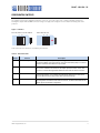
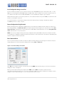
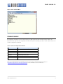
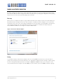
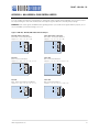
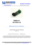
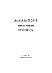
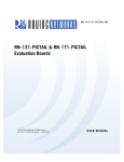
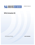
 RN-BT-SRL-UM
Bluetooth Serial Adapter
© 2011 Roving Networks. All rights reserved.
RN-BT-SRL-UM-1.0 Version 1.0 11/11/2011
USER MANUAL
RN -BT -SR L-U M- 1.0
OVERVIEW
Roving Networks offers a variety of Bluetooth serial adapters with different form factors and powering options (see Table 1).
These adapters enable wireless connection to any legacy serial port and support bi-directional RS-232 or RS-422 signaling
at a rate of up to 464 Kbps. To create a wireless cable replacement solution, simply attach the adapter to your device's
RS-232 or EIA-232/422 port and connect to it over Bluetooth. The transmission range is up to 330 feet (100 meters),
depending on environmental factors.
You can use these adapters as Bluetooth master or slave devices. The serial port profile (SPP) connection to the adapter
appears via a virtual COM interface. Data is sent and received on the client side as if a serial cable was connected to a real
COM port on the client.
You can also use the adapters in cable replacement mode in which two Roving Networks’ Bluetooth devices are paired
using configuration switches. The USB-to-Bluetooth (RN-USB-X) dongle has pairing switches and you can use it with the
Bluetooth adapter to create a wireless connection to a PC without using the PC’s Bluetooth stack. For more information on
cable replacement, refer to the Bluetooth Cable Replacement Application Note on the Roving Networks website at
http://www.rovingnetworks.com/Support_Overview.
Table 1. Bluetooth Serial Adapter Hardware Interfaces
Hardware Interface
RN-240
RS-232
RN-422
✔
RS-422
RN-270
RN-274
RN-220XP
✔
✔
✔
✔
POWERING THE SERIAL ADAPTER
The Bluetooth serial adapters are powered using either rechargeable batteries, an external power cable, or using pin 9 of a
DB9 connector, depending on the adapter.
RN-240 & RN-422 Adapters
The RN-240 and RN-422 adapters are powered using either the DC power plug or via pin 9 of a DB9 connector.
RN-270, RN-274 & RN-220-XP Adapters
The RN-270 and RN-274 adapters are powered using two rechargeable AAA batteries, an external power cable, or using
pin 9 on a DB9 connector. The adapter has a red button on it’s top, which is a soft on/off switch. The adapter must have
batteries installed to function, even if the device is powered externally.
The RN-220XP adapter is powered with a LiPoly battery. The adapter has a toggle on/off switch.
WARNING: Do NOT use alkaline batteries when connecting the external power cable or applying power on pin 9 of the
DB9 connector.
www.rovingnetworks.com
2
RN -BT -SR L-U M- 1.0
Turning the Adapter On & Off
To turn the adapter on, press the red button for 1 second until the green and blue LEDS begin flashing and then release it.
After a moment, the blue LED goes off and the green LED remain flashing to indicate the device is turned on and not
connected.
To turn the adapter off, press the red button for 1 second until the green and blue LEDs begin flashing and then release it.
All the LEDs turn off.
By default, the adapter automatically turns off if it is not connected over Bluetooth for more than 3 minutes (i.e., 180
seconds). You can control the sleep timer duration using the S+ command. For example, S+,600” sets the timer to 10
minutes.
Use the O command to display the sleep timer’s current settings.
Batteries & Charging
Only use NiMH rechargeable batteries when externally powering the adapter. Applying power with alkaline batteries
installed causes battery acid to leak and destroys the adapter (and surrounding environment).
The red LED turns on solid when external power is present. When the adapter is on, a blinking blue LED indicates low
battery. The battery life between charges depends on use. With typical usage the adapter should operate for at least 10
continuous hours between charges. Enabling sniff mode can extend the battery life (see Table 2).
You can apply external power from either the 5-V DC plug or pin 9 on the DB9 connector. The power plug is center pin
positive, outer cylinder ground. The input MUST be 5-V DC for proper battery charging. Higher voltages can permanently
damage the charger and battery.
Table 2. RN-270 Battery Life Table (Note 1)
Sniff Time (ms)
Sniff Mode
Battery Life
(with Status LEDs)
Battery Life
(without Status LEDs)
0
8 hrs, 20 mins
10 hrs
100
17 hrs
19 hrs, 30 mins
200
17 hrs, 30 mins
20 hrs
400
18 hrs
20 hrs, 30 mins
Notes:
1. The times shown are approximate and should be used as a reference only. Battery life varies depending on the type of batteries
used. New rechargeable batteries tend to have a longer battery life than older rechargeable batteries. Alkaline batteries, Energizer
batteries in particular, tend to last twice as long as rechargeable batteries.
Reducing Power when Connected
You can adjust the power used while connected by setting the sniff mode. By default, sniff mode is disabled and the radio
is active continuously when connected (using about 25 – 30 mA). With sniff mode enabled, the radio sleeps in very low
power mode (around 2 mA) and wakes up at specific intervals. Using sniff mode, the power savings can be quite dramatic.
To enable this mode, use the SW,<hex word> command. Refer to the Bluetooth Advanced User Manual on the Support
page of the Roving Networks website at http://www.rovingnetworks.com/Support_Overview for more information on using
sniff mode.
www.rovingnetworks.com
3
RN -BT -SR L-U M- 1.0
Reducing Power when Disconnected
Low-power connection mode disables the Bluetooth radio and LED timers when the adapter is disconnected. In low-power
mode, the adapter cycles between active (discoverable and connectable) and low power deep sleep. This mode saves
considerable power when the module is waiting for long periods of time without a connection. The trade off is additional
latency when connecting or pairing. Refer to the Bluetooth Advanced User Manual on the Support page of the Roving
Networks website at http://www.rovingnetworks.com/Support_Overview for more information on using the low-power
connection mode.
STATUS LEDS
The adapters have several LED indicators. The green LED shows the Bluetooth connection status and the adapter’s
operational mode:
•
When booting, the LED blinks two times per second.
•
In configuration mode, it blinks ten times per second.
•
When the module is in discoverable or idle mode, it blinks one time per second.
•
When the module is connected, the green LED is on solid.
The yellow LED blinks when data is sent or received on the serial interface. This blinking does not indicate that data was
sent over the Bluetooth connection. If the yellow LED is not blinking when your device sends data to the serial port, the
connection or flow control may be set incorrectly.
Some versions of the RN-240 adapter have a red LED. This LED blinks when data is received over the RF link in low-speed
data mode.
OPERATING MODES
The Bluetooth adapter has several operating modes, which you set using the SM command in command mode:
•
Slave (SM,1)—Default mode, whereby other Bluetooth devices can discover and connect to the adapter.
•
Master (SM,1)—In this low-speed connection mode, the adapter makes connections when a connect command
(C), is received. This command can also contain the Bluetooth address of the remote device. If a device is not
specified, the adapter uses the stored remote address. The connection can be broken if the special break
character or string is sent (use the SO command to set the break character).
•
Trigger (SM,2)—In this low-speed connection mode, the adapter makes connections automatically when a
character is received on the serial port. The connection continues as long as characters are received on either
end. The adapter has a configurable timeout (which you set using the ST command) that disconnects the
adapter after the specified number of seconds (1 to 254) of inactivity.
•
Auto Master (SM,3)—In this mode, the adapter makes connections automatically on power-up, and re-connects
when the connection is lost. You can also enable this mode using switch 2. This mode is a high-speed
connection mode, and cannot be broken by software break characters.
NOTE: In all master modes, the device cannot be discovered or configured remotely over Bluetooth.
www.rovingnetworks.com
4
RN -BT -SR L-U M- 1.0
CONFIGURATION SWITCHES
The adapters have small configuration switches on the top. You need a paper clip or small screwdriver to flip them.
Holding the adapter with the DB9 connector facing to the right, refer to Figure 1 for the switch numbering and on/off
positions.
Figure 1. Switches
RN-240, RN-422 & RN-220-XP
On
RN-270 & RN-274
Off
On
4
3
2
1
Off
4
3
2
1
Table 3 describes the functions controlled by the switches.
Table 3. Switch Functions
Switch
Function
1
Restore factory defaults
Turn on the switch, power up the adapter, and toggle the switch ON-OFF-ON-OFF-ON
to return the adapter to its factory settings. The green LED blinks quickly for a moment
and then continues to blink about once per second.
2
Automatic discovery
In slave mode, this switch sets a special class of device that is used by the master to
auto connect. If switch 3 also turned on, the adapter performs a search, stores, and
connects to a remote Roving Networks Bluetooth device that has switch 2 turned on.
3
Automatic master
With this switch turned on, the adapter acts as Bluetooth master and auto-connects to a
stored remote address. You must first set the Bluetooth address of the slave device
using the SR command or using instant cable replacement settings.
4
Default baud rate
With this switch turned off, the default 115 K baud rate is overridden by software baud
rate configuration commands. If this switch is turned on, the baud rate is 9600 and the
adapter ignores the software configuration.
www.rovingnetworks.com
Description
5
RN -BT -SR L-U M- 1.0
CONFIGURATION
The Bluetooth adapter operates in two modes: data mode (default) and command mode. While in data mode, the module
is essentially a data pipe. When the module receives data, it strips the Bluetooth headers and trailers and passes the user
data to the UART. When data is written to the UART, the module constructs the Bluetooth packet and sends it out over the
Bluetooth connection. Thus, the entire process of sending/receiving data to the host is transparent to the end
microprocessor. See Figure 2.
Figure 2. Data & Command Modes
Host
Bluetooth
User Data
B
A
UART
Bluetooth
Module
$$$
Bluetooth Interface
A
B
$$$
Command
Mode
The default configuration for the Bluetooth adapter is:
•
Bluetooth slave mode
•
Bluetooth pin code 1234
•
Serial port 115,200 Kbps baud rate, 8 bits, no parity, 1 stop bit
•
Serial port flow control disabled
•
Low power mode off
You configure the adapter by putting it into command mode and sending ASCII commands over a serial port or the
Bluetooth link. Once you change the configuration parameters, they persist until changed or you perform a factory reset.
There are two ways to configure the Bluetooth module:
•
Local configuration using your computer’s serial port
•
Via Bluetooth
You need a terminal emulator to complete the setup.
NOTE: Roving Networks suggests using either the TeraTerm (Windows OS) or CoolTerm (Mac OS-X) terminal emulator
program.
www.rovingnetworks.com
6
RN -BT -SR L-U M- 1.0
Local Configuration Using a Serial Port
Connect the Bluetooth adapter to your computer’s serial port. (The RN-240M may require a null-modem cable, i.e., with
DB9 pins 2 and 3 swapped; the RN-240F requires a straight cable). If your computer does not have a serial port, you can
use a USB-to-serial cable such as the RN-USB-SERIAL to connect the Bluetooth adapter to your computer.
With the Bluetooth adapter connected and powered on, run a terminal emulator and open the COM port to which the serial
interface or serial USB is connected.
The terminal emulator’s communication settings should be the default serial port settings of the Bluetooth adapter:
115,200 Kbps, 8 bits, no parity, 1 stop bit.
Remote Configuration Using Bluetooth
Before performing remote configuration using Bluetooth, you must first pair the Bluetooth device with your computer. For
PCs running Windows, click Bluetooth devices in the system tray at the bottom right of your computer screen. Select Add
a Bluetooth device and follow the on-screen instructions. For Mac OS-X, click the Bluetooth icon, select Set up Bluetooth
device, and follow the on-screen instructions.
NOTE: You can only configure remotely if the bootup configuration timer (default 60 seconds) has not expired. This timer
is set to 0 (remote configuration disabled) for master mode and auto-connect slave mode so that data can immediately flow
between 2 adapters for cable replacement.
Enter Command Mode
Launch a terminal emulator and make sure that the adapter’s default settings are selected. Figure 3 shows the serial port
settings dialog box for TeraTerm (open this dialog box by choosing Setup > Serial Port).
Figure 3. Serial Port Settings in TeraTerm
Type $$$ into the terminal emulator. It should return the string CMD, which indicates that your connection and terminal
settings are correct. See Figure 4.
When you enter a valid command, the adapter returns AOK. It returns ERR for an invalid command and ? for
unrecognized commands. Type h <cr> to see a list of commands, and d <cr> to view a summary of the adapter’s current
settings. To return to data mode, type --- <cr> or reset the device and re-connect.
www.rovingnetworks.com
7
RN -BT -SR L-U M- 1.0
Figure 4. Enter Command Mode
COMMAND SUMMARY
All configuration information is stored in flash memory. The set command modifies the flash memory; however, the
Bluetooth module only reads the configuration from flash memory when powering up or after a reboot. Table 4 shows some
common configuration commands.
Table 4. Common Configuration Commands
Command
Description
SU,9600
Sets the UART baud rate to 9600.
SN,myname
Sets the Bluetooth name to myname.
SA,1
Enables secure authentication.
SP,secret
Sets security code to secret.
SF,1
Restores all values to the factory defaults.
R,1
Reboots the module.
Refer to the Bluetooth Advanced User Manual on the Support page of the Roving Networks website at
http://www.rovingnetworks.com/Support_Overview for more information on the command set.
www.rovingnetworks.com
8
RN -BT -SR L-U M- 1.0
MAKING A BLUETOOTH CONNECTION
By default, the Bluetooth adapter acts as a slave and the PC is the master. You connect to the Bluetooth adapter using
your computer’s Bluetooth device manager, which varies depending on the operating system. Regardless of the operating
system, the process is the same: discovery, pairing, and connecting.
Discovery
When you turn on the Bluetooth adapter, the green LED should blink and the adapter should be discoverable. Open your
PC’s Bluetooth device manager and choose to add a new device. The Bluetooth device manager’s icon is located in the
bottom right corner of your screen in the taskbar for Windows and in the upper right corner for Mac OS-X. The Bluetooth
device manager displays a list of discoverable Bluetooth devices (see Figure 5). The Bluetooth adapter displays as
FireFly-XXXX where XXXX is the last 4 digits of the adapter’s MAC address.
Figure 5. Discover the Bluetooth Adapter
Pairing
To pair with the adapter, double-click the adapter’s name (i.e., FireFly-XXXX) in the list. Choose to enter the device’s
pairing code (see Figure 6) and enter the default pin code, 1234. When the Bluetooth device manager completes pairing,
it issues a message that the Bluetooth device is installed on COMX where COMX is unique to your computer. In some
cases, the Bluetooth device manager creates two COM ports; in this situation, only use the COM port labeled “outgoing.”
www.rovingnetworks.com
9
RN -BT -SR L-U M- 1.0
Figure 6. Pair with the Bluetooth Adapter
NOTE: You only need to pair with the adapter once.
Connecting
To establish a Bluetooth connection, open the adapter’s COM port from your application or a terminal emulator. When the
COM port is open, the adapter’s green LED changes from blinking to solid on. The device remains connected until you
close the COM port or turn off the Bluetooth adapter.
Security Modes
The Bluetooth adapter supports authentication. If the local or remote Bluetooth device has authentication enabled, a pin
code is required the first time a connection is attempted. The pin code is a series of numbers or characters.
NOTE: The default pin code for Roving Networks Bluetooth adapters and modules is 1234.
After you enter the pin code, the Bluetooth devices compare them. If they match, a link key is generated and stored.
Usually, but not always, the remote device stores the link key. For subsequent connections, the devices compare link keys.
If they are correct, you do not need to re-enter the pin code.
If the remote device is a PC or PDA, the user generally is prompted to enter this pin code. To remove the stored link key on
the remote device, you typically “unpair” or remove the device from the Bluetooth manager. You can change the pin code
to remove the link key on the Bluetooth adapter, forcing a new pin code exchange to occur upon subsequent connection
attempts.
NOTE: Only one master can connect to the Bluetooth adapter at a time.
www.rovingnetworks.com
10
RN -BT -SR L-U M- 1.0
SERIAL CONNECTOR SPECIFICATION
The Bluetooth serial adapters have male or female DB9 connectors. Refer to Figure 7 and Table 5 for the pin-out.
Figure 7. DB9 Connector Pins
1
5
6
9
Table 5. DB9 Connector Pin-Out
Pin
RN-220XP& RN-270M
Male DB9
RN-240F & RN-270F
Female DB9
RN-422M & RN-274M
Male DB9
1
NC
NC
NC
2
RXD
TXD
NC
3
TXD
RXD
RXD-
4
NC
NC
TXD+
5
6
GND
NC
GND
NC
GND
+5 VDC (Input)
7
RTS
CTS
RXD+
8
CTS
RTS
TXD-
9
4 – 12 VDC
4 – 12 VDC
NC
NOTE: The RS-232 interface uses the SIPEX SP3232ECA chip with capacitor switch to generate the + and – signals,
therefore, it is not driving the full RS-232 voltages. Devices stealing power from the RS-232 pins may not have enough
voltage.
RESOURCES & RELATED DOCUMENTS
For more information, refer to the following sources, which are available on the Support page on the Roving Networks
website at http://www.rovingnetworks.com/Support_Overview:
•
Bluetooth Advanced User Manual
•
Bluetooth Cable Replacement Application Note
•
Drivers, tools, and utilities
www.rovingnetworks.com
11
RN -BT -SR L-U M- 1.0
APPENDIX A - NULL MODEM & FLOW CONTROL JUMPERS
You can configure the adapter’s serial interface to enable flow control and null modem signaling. You access the jumper
block by removing the cover from the Bluetooth serial adapter. Figures 10 and 11 show the jumper settings.
WARNING: Flow control signals are NOT RS-232 signaling tolerant. If you enable these signals with the jumpers, do not
exceed 3.3-V DC or permanent damage can occur.
Figure 8. RN-422, RN-240, RN-270 & RN-274 Jumpers
Male DB9 (Default Configuration)
DTE 3 Wire - Flow Control Disabled
Jumper 1 < > 2, 3 < > 4, 9 < > 10
1
3
5
7
9
2
4
6
8
10
Male DB9
DTE - Flow Control Enabled
Jumper 1 < > 2, 3 < > 4, 5 < > 6, 7 < > 8
1
3
5
7
9
2
4
6
8
10
Male DB9
DCE - Flow Control Enabled, Null Modem
Jumper 1 < > 3, 2 < > 4, 5 < > 6, 7 < > 8
1
3
5
7
9
2
4
6
8
10
Female DB9 (Default Configuration)
DTE 3 Wire - Flow Control Disabled
Jumper 1 < > 3, 2 < > 4, 9 < > 10
1
3
5
7
9
2
4
6
8
10
Female DB9
DTE - Flow Control Disabled
Jumper 1 < > 3, 2 < > 4, 5 < > 6, 7 < > 8
1
3
5
7
9
2
4
6
8
10
Female DB9
DTE - Flow Control Enabled
Jumper 1 < > 2, 3 < > 4, 5 < > 7, 6 < > 8
1
3
5
7
9
2
4
6
8
10
www.rovingnetworks.com
12
RN -BT -SR L-U M- 1.0
Figure 9. RN-220XP Jumpers
Male DB9 (Default Configuration)
DTE 3 Wire
Jumper 1 < > 2, 7 < > 8, 9 < > 10
1
3
5
7
9
2
4
6
8
10
Male DB9
DCE - Flow Control Enabled
Jumper 3 < > 4, 5 < > 6, 7 < > 8, 9 < > 10
1
3
5
7
9
2
4
6
8
10
Male DB9
DCE - Flow Control Disabled
Jumper 1 < > 2, 7 < > 9, 8 < > 10
1
3
5
7
9
2
4
6
8
10
www.rovingnetworks.com
13
RN -BT -SR L-U M- 1.0
APPENDIX B - INSTANT CABLE REPLACEMENT
You can use the Roving Networks adapters (with or without the FirePlug USB dongle, RN-USB-X) for cable replacement
with the following steps:
1.
Turn off the adapters and set the switches as shown in Figure 10.
Figure 10. Cable Replacement Switch Settings
Master Mode
Auto Discovery &
Auto Master Turned On
On
Slave Mode
Auto Discovery Turned On
Off
On
4
3
2
1
Off
4
3
2
1
2.
Power up both devices. The master discovers the slave device, stores its Bluetooth address, and connects. The
devices are now paired and each device’s green LED should be on solid.
3.
Set switch 2 on both devices to off so that they do not try to re-pair each time power is cycled. See Figure 11.
Figure 11. Setting Switch 2
Master Mode
On
Slave Mode
Off
4
3
2
1
On
4
3
2
1
Off
Once paired, when the devices are in range of each other, they connect and the master will not attempt to connect to any
other Bluetooth device. To break the pairing, restore the factory defaults using switch 1.
For more information on instant cable replacement, refer to the Bluetooth Cable Replacement Application Note on the
Roving Networks website at http://www.rovingnetworks.com/Support_Overview.
www.rovingnetworks.com
14
RN -BT -SR L-U M- 1.0
NOTES
www.rovingnetworks.com
15
RN -BT -SR L-U M- 1.0
Copyright © 2011 Roving Networks. All rights reserved. Roving Networks is a
registered trademark of Roving Networks. Apple Inc., iPhone, iPad, iTunes, Made
for iPhone are registered trademarks of Apple Computer.
Roving Networks reserves the right to make corrections, modifications, and other
changes to its products, documentation and services at any time. Customers
should obtain the latest relevant information before placing orders and should verify
that such information is current and complete.
Roving Networks, Inc.
102 Cooper Court
Los Gatos, CA 95032
+1 (408) 395-5300
www.rovingnetworks.com
www.rovingnetworks.com
Roving Networks assumes no liability for applications assistance or customer’s
product design. Customers are responsible for their products and applications
which use Roving Networks components. To minimize customer product risks,
customers should provide adequate design and operating safeguards.
Roving Networks products are not authorized for use in safety-critical applications
(such as life support) where a failure of the Roving Networks product would
reasonably be expected to cause severe personal injury or death, unless officers of
the parties have executed an agreement specifically governing such use.
16