1
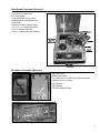
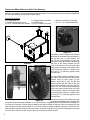
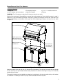
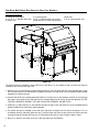
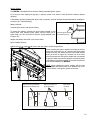
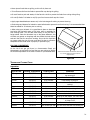
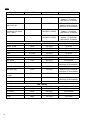
SHERWOOD INDUSTRIES IS AN ENVIRONMENTALLY RESPONSIBLE COMPANY. THIS MANUAL IS PRINTED ON RECYCLED PAPER.
PLEASE KEEP THESE INSTRUCTIONS FOR FUTURE REFERENCE
BISTRO 4500
BY: SHERWOOD INDUSTRIES LTD
OWNER’S MANUAL
NOTE: This appliance must not be used indoors.
WHAT TO DO IF YOU SMELL GAS
• Open windows/extinguish any open flame.
• Do not try to light any appliance.
• Do not touch any electrical switch or use any phone in your building.
• Immediately call your gas supplier from a neighbour’s phone. Follow the
gas supplier’s instructions.
• If you cannot reach your gas supplier, call the fire department.
FOR YOUR SAFETY
Do not store or use gasoline or other flammable vapours and liquids in the
vicinity of this or any other appliance.
A propane (LP) cylinder not connected for use shall not be stored in the vicinity
of this or any other appliance.
Table of Contents
Safety Precautions.................................................................................................................3
Specifications........................................................................................................................4
Dimensions...............................................................................................................4
Orifice Sizes..............................................................................................................4
Clearances To Combustibles.......................................................................................4
Assembly Instructions............................................................................................................5
Tools Required...........................................................................................................5
Cart Components.......................................................................................................5
Engine Components...................................................................................................6
Side Burner Components (Optional)............................................................................7
Rotisserie Components (Optional)...............................................................................7
Casters and Wheels Installed Onto Cart Assembly........................................................8
Engine Installed Onto Cart Assembly...........................................................................9
Side Shelf And Utensil Rack Installed Onto Cart Assembly...........................................10
Side Burner Installed Onto Cart Assembly (Optional)..................................................11
Rotisserie Installed Onto Cart Assembly (Optional).....................................................12
Grill Removal...........................................................................................................12
Installing Propane Cylinder In Cabinet.......................................................................13
Hooking Up To Gas Supply.....................................................................................................14
Propane..................................................................................................................14
Natural Gas.............................................................................................................14
Operating Instructions..........................................................................................................15
Burner Flame Appearance and Adjustment.............................................................................16
Routine Maintenance and Inspection......................................................................................17
Cooking on Your Grill............................................................................................................20
Methods of Cooking.................................................................................................20
Preparing Food For The Bistro...................................................................................20
Grilling Tips.............................................................................................................20
Temperature Cooking Chart......................................................................................21
Troubleshooting.................................................................................................................23
Parts Diagram - Grill..............................................................................................................24
Parts Diagram - Hood............................................................................................................25
Parts Diagram - Cart..............................................................................................................26
Parts Diagram - Side Shelf & Burner........................................................................................27
Parts List.............................................................................................................................28
Warranty..............................................................................................................................29
Installation Data Sheet.........................................................................................................30
2
Safety Precautions
Please read these instructions before assembling or operating this outdoor cooking appliance.
The ENVIRO BISTRO is designed for outdoor use only.
The ENVIRO gas barbecue must be installed and operated in accordance with the installation requirements of your
local gas supply authority or the appropriate installation code in the area of installation. In the absence of local
codes, use either the National Fuel Gas code, ANSI Z223.1, or CAN/CGA-B149.1, National gas Code or CAN/CGAB149.2, Propane Gas Code.
If an external electrical source is utilized, this gas grill, when installed, must be electrically grounded in accordance
with the local codes or, in the absence of local codes, with the National Electrical Code, ANSI/NFPA 70, or the
Canadian Electrical Code, CSA C22.1.
Keep electrical cord and the fuel source hose away from any heated areas.
This outdoor gas grill is not intended for use in or on recreational vehicles and or boats.
Operate this gas grill only in areas free of obstructions for combustion and ventilation air.
The exterior surfaces of this gas grill can become very hot when in use. Exercise caution. Use protective gloves
and/or pot holders.
DO NOT USE THIS APPLIANCE IN AN ENCLOSED AREA.
Examples of enclosed areas are garages, sheds or enclosed sundecks or any other enclosed areas. Do not use this
gas grill under overhead, unprotected combustible materials such as awnings or umbrellas.
KEEP CHILDREN AWAY.
Do not allow children to operate this appliance. Keep children and pets away from barbecue during use.
CHECK FOR GAS LEAKS.
Once the barbecue has been assembled and installed, make sure the gas knobs and valves are in the “OFF” position.
Turn gas “ON” at the source. Use a small brush to apply a warm soapy water solution to all gas connections (use a
half dish soap and half warm water). If a gas leak is present, bubbling will occur. Gas leaks can be repaired by using
an approved pipe thread sealant or approved Teflon tape. The flexible gas hose must be inspected before each use.
NEVER USE AN OPEN FLAME WHEN TESTING FOR LEAKS.
LPG GAS CYLINDER.
An approved 20 lb. gas cylinder is required for optimum performance and
convenience.
Manual shutoff valve
Collar
LPG gas cylinder is not provided with this appliance. When purchasing a
LPG cylinder, make sure the cylinder has a manual shut off valve and that
the cylinder has a collar to protect the manual shut off valve.
LPG gas cylinder must be constructed and marked in accordance with
specifications of the U.S. Department of Transport (DOT). In Canada gas
cylinders must meet Canadian Transportation and Communications (CTC)
specifications.
Lift the LPG cylinder by its collar, never from the valve.
Figure 1
NEVER CONNECT AN UNREGULATED LP GAS CYLINDER TO YOUR BARBECUE.
DO NOT SUBJECT LP GAS CYLINDERS TO EXCESSIVE HEAT.
WHEN THE APPLIANCE IS NOT IN USE, THE GAS SUPPLY SYSTEM MUST BE TURNED “OFF” AT THE
SOURCE.
KEEP APPLIANCE AWAY FROM ANY COMBUSTIBLE MATERIALS.
VISUALLY INSPECT THE RUBBER GAS HOSE AND CONNECTIONS AND BURNERS ON A REGULAR
BASIS TO ENSURE NO DAMAGE OR DETERIORATION IS PRESENT.
3
Specifications
DIMENSIONS:
Width:
Depth at bottom:
Height to side shelf:
Overall height:
64
22
34
49
/ inches
/16 inches
15/16 inches
7⁄8 inches
1 16
7
(162.7 cm)
(56.9 cm)
(88.7 cm)
(126.6 cm)
��������
�������
�������
�������
���������
��������
Figure 2
ORIFICE SIZES:
Bistro 4500
Main
Rear
Side
Natural Gas (NG)
#51 DMS
#46 DMS
#51 DMS
Propane (LPG)
#56 DMS
#54 DMS
#56 DMS
CLEARANCES TO COMBUSTIBLES:
DO NOT USE THIS APPLIANCE IN AN
ENCLOSED AREA, for example: Garages,
sheds or enclosed sundecks or any other
enclosed areas. Do not use this gas grill under
overhead, unprotected combustible materials
such as awnings or umbrellas.
KEEP THIS APPLIANCE FREE FROM
COMBUSTIBLE MATERIALS.
�
�
DO NOT OBSTRUCT THE FLOW OF
COMBUSTION AND VENTILATION AIR
KEEP THE VENTILATION OPENINGS AROUND
THE LPG GAS CYLINDER ENCLOSURE CLEAR
AND FREE OF DEBRIS
Rear to unit
A: 16 Inches (40.6 cm)
Side to unit
B: 8 Inches (20.3 cm)
Figure 3
4
Assembly Instructions
Your ENVIRO BISTRO will require some assembly. Please do not use a drill to modify any component, it is not
necessary. Inspect all components for damage before assembly begins. If damage is present, please contact
your local dealer or a courier company. Replace the damaged components with original manufacturer’s parts, no
substitutions will be permitted. Do not commence construction if components are damaged or missing.
The Cart assembly and Main Engine have been pre-assembled for convenience and ease of assembly.
TOOLS REQUIRED:
● 1⁄4” socket or nut driver
●11/16” wrench or adjustable wrench
● 5/32” Allen key (supplied)
● 7/16” wrench or adjustable wrench
● 3⁄4” wrench or adjustable wrench ● Hammer or mallet
CART COMPONENTS:
●
●
●
●
Pre-assembled cart
(2) Stainless steel axle mount
Side shelf
(30) 1⁄4” stainless steel lock washers
●
●
●
●
(2) Plated caster assemblies
(2) BBQ wheels
Side shelf top
(20) 1⁄4” stainless steel nuts
●
●
●
●
Aluminum axle and (2) end caps
(2) Shelf gussets
(30) 1⁄4” x 1⁄2” stainless steel bolts
5/32” Allen key
Once the cart assembly has been removed from the
packaging, open the doors and remove all the objects
from inside of the cart. The cart will look similar to
Figure 4.
There should be a small box, a large box, the aluminum
axle and some packaging materials.
Figure 4
2 Shelf Gussets
The components shown in Figure
5 should be found in the larger
box.
Side Shelf
Most of the stainless steel
components are covered with
plastic to prevent scratching the
unit during assembly. This can be
removed
Side Shelf Top
Figure 5
5
2 plated caster
assemblies
2 BBQ wheels
The components shown in Figure 6 should be
found in the smaller box.
2 stainless steel
axle mounts
Figure 6
ENGINE COMPONENTS:
●
●
●
●
Pre-assembled engine
Metal Foil Container
Grill removal tool
(8) 1⁄4” x 1⁄2” stainless steel bolts
●
●
●
●
(3) Flame diffusers
Utensil rack
Warranty card
(2) 1⁄4” stainless steel nuts
●
●
●
●
Warming Rack
Owner’s manual
Hose with pressure regulator
(8) 1⁄4” stainless steel lock washers
When the top of the shipping box has been removed and the lid
has been opened, it will look similar to Figure 7.
A metal foil container is taped to the warming rack and the
warming rack is taped to the windshield. All tape must be removed
from inside the engine before your Bistro 4500 is started for the
first time. The three flame diffusers are stacked and the rest of
the components will be found in the manual bag.
Utensil rack
Hose with pressure
regulator
Grill removal
tool
Figure 7
The components shown in Figure 8 should
be found in the manual bag found inside the
engine.
Warranty
card
Bag of hardware
Figure 8
6
SIDE BURNER COMPONENTS (OPTIONAL):
●
●
●
●
●
●
●
●
●
Pre-assembled side burner
(2) Shelf gussets
Cast side burner grill (2 pieces)
Side burner porcelain diffuser cap
NG Orifice
Nutdriver (used to change orifice)
(10) 1⁄4” x 1⁄2” stainless steel bolts
(4) 1⁄4” stainless steel nuts
(10) 1⁄4” stainless steel lock washers
Cast Side Burner
Grill
Side Burner
Porcelan
Diffuser Cap
Nutdriver
NG Orifice
Bag of
Hardware
Side Burner
Figure 9
ROTISSERIE COMPONENTS (OPTIONAL):
●
●
●
●
●
●
●
Figure 10
Rotisserie Motor
Side mount bracket
(4) Stainless steel thread rolling screws (one extra)
Rotisserie rod (not shown)
(2) Spit forks
Spit bushing
Counter weight assembly
Figure 11
Figure 12
7
CASTERS AND WHEELS INSTALLED ONTO CART ASSEMBLY:
When the cart cabinet has been emptied the wheels and casters can be installed. Leave the cart body upside down;
this will make installing the wheels and casters easier.
Components Required:
● Pre-assembled cart
● (2) Stainless steel axle mount
● (14) 1⁄4” stainless steel lock washers
● (2) Plated caster assemblies
● (2) BBQ wheels
● (14) 1⁄4” stainless steel nuts
● Aluminum axle and (2) end caps
● (14) 1⁄4” x 1⁄2” stainless steel bolts
Figure 14
The casters must be installed on the bottom
left side of the cart body. Each caster requires
four (4) bolts, four (4) lock washers, and
four (4) nuts. Put the casters in place (see
Figure 13 & 14) and slide the bolts through
the holes in the caster brackets into the
holes in the bottom of the cart body. Open
cabinet doors and place a lock washer and a
nut onto each bolt. Using a 1⁄4” socket or nut
driver and a 5/32” Allen key, tighten all the
nuts and bolts.
Figure 13
The axel mounts must be installed on the
right side of the cart body. Each axel mount
requires three (3) bolts, three (3) lock
washers, and three (3) nuts. Put the axel
mounts in place with the holes for the axel
closest to the bottom of the cart body (see
Figure 13 & 15). Slide the bolts through the
holes in the mount into the holes in the side
of the cart body. Place a lock washer and a
nut onto each bolt. Using a 1⁄4” socket or nut
driver and a 5/32” Allen key tighten all the
nuts and bolts.
Before the wheels can be installed they must
be partially assembled. Press one wheel onto
an end of the axel so that approximately 1⁄2” (1 cm) of the axel is out past the wheel. The side with the webbing on it
is to face out. A hammer or mallet may be needed to help put the wheels on the axel. Press an end cap all the way
onto the end of the axel with the wheel on it; ensure the wheel is butted up against the end cap (see Figure 16).
Slide the axel through the holes in both axel mounts; it may be a tight fit so turn the axel while pressing it through
the holes. Press the other wheel, then the end cap, onto the free end of the axel.
Figure 15
8
Figure 16
ENGINE INSTALLED ONTO CART ASSEMBLY:
Components Required:
● Rolling cart
● (4) 1⁄4” stainless steel lock washers
● Pre-assembled engine
● Metal Foil Container
● (4) 1⁄4” x 1⁄2” stainless steel bolts
● Drip tray
WARNING: Two (2) people are required to lift the engine onto the cart safely.
Empty all the components (frame deflectors, manual bag, and warming tray) from inside the engine to make it
lighter to lift. Turn the cart body right side up. Using two (2) people, lift the engine onto the cart. Take care to line
up the manifold fitting on the bottom of the engine with its corresponding cut away on the top of the cart. Refer
to Figure 17.
������������� ������
������ ������ �� ����
���� ���� ��� ����� ���
���� ��� �������������
����� ���� ��������� ��
��������� �����
������ ���� ����
��� �� ���� ����
�������� ��������
��������� ����
Figure 17
Attach the engine to the cart with four (4) bolts and four lock-washers. The bolts go from inside the cart through
the top of the cart into pre-threaded inserts already installed in the bottom of the engine. Using a 5/32” Allen key
tighten all four (4) bolts.
The metal foil container can be installed at any stage but is pointed out in this step to provide clarity on the location
for installation. If installing at a later time, open cabinet and slide container into place.
9
SIDE SHELF AND UTENSIL RACK INSTALLED ONTO CART ASSEMBLY:
Components Required:
● Rolling cart with engine
● (12) 1⁄4” x 1⁄2” stainless steel bolts
● Utensil rack
● (2) Shelf gussets
● (12) 1⁄4” stainless steel lock washers
● Side shelf top or corian cutting board
● Side shelf
● (6) 1⁄4” stainless steel nuts
Figure 18
The side shelf can be installed on either side but if a side burn is to be installed as well, the side shelf must be
installed on the left side (see Figure 18).
1. Attach the two (2) shelf gussets (formed edges pointing in) onto the front and rear of the left side panel, using
four (4) bolts and four (4) lock-washers, through the inside of the side shelf into pre-threaded inserts already
installed in the side of the cart.
2. Place the side shelf on the shelf gussets and install four (4) bolts, four (4) lock-washers, and four (4) nuts through
the holes in the bottom of the side shelf and the corresponding hole at the top of the shelf gussets. DO NOT
TIGHTEN THESE BOLTS ENTIRELY, THIS WILL HELP WITH ALIGNMENT FOR NEXT STEP.
3. Install two (2) bolts and two (2) lock-washers through the side of the side shelf into the pre-threaded inserts
already installed in the side of the engine assembly.
4. The utensil rack can be installed on the side of the side shelf or directly onto the side of the engine. If it is to
be installed onto the side shelf, place the two (2) bolts through the holes on each end of the utensil rack then
through the side of the side shelf. Use two (2) lock-washers and two (2) nuts to hold the bolts in place.
5. Using a 1⁄4” socket or nut driver and a 5/32” Allen key tighten all the fasteners.
10
SIDE BURNER INSTALLED ONTO CART ASSEMBLY (OPTIONAL):
Components Required:
● Rolling cart with engine
● Side Burner
● (4) 1⁄4” stainless steel nuts
● (2) Shelf gussets
● Side burner porcelain diffuser cap
● (10) 1⁄4” x 1⁄2” stainless steel bolts
● Cast side burner grill (2 pieces)
● Side shelf top or corian cutting board
● (10) 1⁄4” stainless steel lock washers
Flexible stainless steel gas line
Cap on side burner outlet
Figure 19
The side burner must be installed on the right side. The initial installation steps for the side burner are very similar
to the side shelf so you may refer to Figure 18.
1. Attach the two (2) shelf gussets (formed edges pointing in) onto the front and rear of the right side panel, using
four (4) bolts and four (4) lock-washers through the inside of the side shelf into pre-threaded inserts already
installed in the side of the cart.
2. Place the side burner on the shelf gussets and install four (4) bolts, four (4) lock-washers, and four (4) nuts
through the holes in the bottom lip of the side burner and the corresponding hole at the top of the shelf gussets.
DO NOT TIGHTEN THESE BOLTS ENTIRELY, THIS WILL HELP WITH ALIGNMENT FOR NEXT STEP.
3. Install two (2) bolts and two (2) lock-washers through the side of the side burner, accessed through the open
bottom of the side burner, into the pre-threaded inserts already installed in the side of the engine assembly.
4. Using a 1⁄4” socket or nut driver and a 5/32” Allen key tighten all the fasteners.
5. Once the side burner has been installed the gas line must be connected. Using a
installed on side burner outlet on the right side of the engine (see Figure 19).
11/16”
wrench remove the cap
6. Attach the flexible stainless steel gas line to the side burner outlet using a 3⁄4”.
7. When the gas has been attached to the Bistro 4500 (see “Hooking Up To Gas Supply” section), turn on the
main gas supply and perform a leak test. Using a liquid dish soap and water solution, spray or brush on all gas
connections. If large bubbles are present this is the sign of a gas leak. Re-tighten gas connections and leak test
once again until there are no signs of bubbling.
11
ROTISSERIE INSTALLED ONTO CART ASSEMBLY (OPTIONAL):
Components Required:
● Rolling cart with engine
● (3) Stainless steel thread rolling screws
● Spit bushing
● Rotisserie Motor
● Rotisserie rod
● Counter weight assembly
● Side mount bracket
● (2) Spit forks
���� �������
������� ������
���������� ���
����� ������ ���� ������� ��� ��������
Figure 20
1. Install the motor mounting bracket onto the left side of the engine with the three (3) screws provided.
2. Slide the rotisserie motor into the mounting bracket.
3. Place the forks, counterweight, and spit bushing onto the rotisserie rod (see Figure 20). If cooking a large item
on the rotisserie, the forks are not mandatory.
4. Slide the pointed end of the rotisserie rod into the rotisserie motor and rest the groove in the bushing on the
notched right side of the windshield.
NOTE: DO NOT USE ROTISSERIE MOTOR IN THE RAIN AND REMOVE MOTOR WHEN NOT IN USE.
DO NOT USE THE WARMING RACK IF THE ROTISSERIE IS BEING USED.
GRILL REMOVAL:
������� ������
����� ����������
����� ������� ����� ����� ����
���� �� ������� ��� ���� ��
��� ������� ����� ��� ���� ��
��� ��� ���� ��� ����� ����
Figure 21
12
INSTALLING PROPANE CYLINDER IN CABINET:
To install the propane cylinder
open the doors to the cabinet,
remove the two (2) 1⁄4” nuts
and bolts holding the tank hole
cover plate (shown in Figure 22).
Remove the plate covering the
hole. Place the propane cylinder
inside the cabinet and drop it
into the hole provided in the
bottom shelf of the cabinet.
Figure 22
Secure the tank to the cabinet
using the attached propane tank
holder. Simply undo the wing
nut provided, slide the mount
over the collar of the propane
tank and tighten the wing nut
until secure (see Figure 23).
Install the gas line from the
propane cylinder as shown in
“Hooking Up To Gas Supply Propane” on next page.
Figure 23
13
Hooking Up To Gas Supply
PROPANE:
FOR YOUR SAFETY: Do not store or use gasoline or other flammable vapors
in the vicinity of this or any other appliance.
Other LPG cylinders not connected to the appliance should not be stored in the
vicinity of this or any other appliance.
A hose and pressure regulator must be used. If a replacement hose and regulator
is required, it must be one supplied by the manufacturer. Refer to “Parts List” for
product number.
Propane Gas (LPG) Connection:
1. Ensure that all the burner control knobs are in the OFF position.
2. Install the LP gas cylinder in the hole provided in the base of the gas grill. Refer to
“Installing Propane Cylinder In Cabinet” section on previous page.
3. Connect the gas supply regulator. Insert the nipple of the valve coupling into the
tank valve and tighten the connection by turning the connection clockwise (see
Figure 24) while holding the regulator with the other hand.
TEST FOR LEAKS:
Figure 24
Before operating the gas grill:
1. Ensure that all burner control knobs are in the OFF position.
2. Connect the gas supply hose and open the shut off valve on top of the LPG cylinder.
3. Use a spray bottle or a brush and apply a soap and water solution (half warm water and half liquid dish soap) to
all gas line connections and joints.
4. Look for bubbles. The appearance of these bubbles indicates a gas leak. Turn off the gas supply and tighten the
joint were the bubbling occurred. Turn the fuel supply back on and retest with the soapy solution once again.
Repeat this procedure until all gas leaks have been repaired.
NATURAL GAS:
To Connect Gas Line:
1. Push back the sleeve on the socket as shown below.
2. Insert the plug and release the sleeve.
3. Push the plug until the sleeve snaps in forward to lock the
plug in place.
To Disconnect Gas Line:
1. Push the sleeve back and pull the plug out of the socket.
Figure 25
A qualified service agency or installer should perform all gas supply plumbing. In the U.S.A., the supply connection
must be made in accordance with local codes or in the absence of local codes, with the National Fuel Gas Codes,
ANSI Z233.1. In Canada, the gas supply connection should be carried out in accordance with the authority having
jurisdiction and in accordance with the requirements of the CAN/CGA 1-B149.1 and 2 installation code. A manual
shut off valve must be installed between the Gas Grill and the fuel supply system.
The outdoor cooking appliance must be disconnected from the fuel supply system before any pressure testing of
the system exceeds 1⁄2 psi (3.5 kPa)
Check the rating label located on the back of this appliance to confirm that the burner valves and orifices are
configured to burn Natural Gas. If required, install a Natural Gas conversion kit available through your ENVIRO
dealer.
14
Operating Instructions
Please read the “SAFETY PRECAUTIONS” section in this manual before you start the unit for the first time, when
the gas supply has been turned off, or whenever the gas cylinder has been changed.
Make sure the orifices, venturis, and main burners are free from obstructions. Perform a gas leak check as described
on page 14 of this manual.
IGNITION:
1. The unit is equipped with an ignition system that will direct a spark to all burners at the same time.
2. Ensure that all burner control knobs are in the “OFF” position.
3. Turn fuel supply “ON” at the source.
4. Open the lid to the barbecue and do not put your head over gas grill before lighting. Push the center gas control
knob counter clockwise to the high flame setting and depress the ignitor button until the burner lights. To light
other burners turn the desired knob counter clockwise and depress ignitor button until main burner lights. Use
this same procedure to ignite rear burner and side burner (hot plate) if equipped.
5. Ensure that the burner is lit and check the flame for proper appearance and operation (see Figure 28). If the
electric ignitor does not operate, remove the grills from the unit and the flame diffusers beneath the grills and
light the burners using a match or flame tamer.
NOTE: Each burner must have the ignition button depressed in order to ignite each burner.
This lighting operation should only take 4-6 seconds. IF THE BURNERS DO NOT IGNITE turn gas knobs to the
“OFF” position and wait 5 minutes to clear any gas that could have accumulated in and around the barbecue.
TEMPERATURE SETTING:
The temperature settings on this barbecue are labeled high to low flame and the control knob can be set any were
in this temperature range on all burners. To preheat this unit, close the lid and monitor the thermometer located
on the lid.
TURNING THE UNIT “OFF”:
Turn the gas control knob clockwise to the “OFF” position when the unit is not being used or when you have finished
cooking with the barbecue. Always turn the main gas supply “OFF” at the source when not in use.
����� ���� �� �������
���� ������ ���� ���
���� ������ ���
���� ������ ���� �� ���
������� ���������
Figure 26
���� ������
���� ������
������ ������
�������
����� ������
Figure 27
15
Burner Flame Appearance and
Adjustment
���� ������ �������
��� ������ ���� ���� ��� ��������
���� ������� ���� �������
��� ���� ���� ����� ��� ��������
���� ���� �������
������� ������ ���� ��� �������
�� ������ �����
Figure 28
1. Remove the cooking grates from the gas grill.
2. Remove the flame deflectors located below the cooking grates.
3. Remove the burner tube. Undo one screw and the mounting plate on the rear of the gas grill and lift burner tube
out.
4. Loosen the single setscrew that holds the venturi air shutter adjustment on the burner tube.
5. If the flame was too yellow and lazy in appearance then open the air shutter until a soft blue flame is achieved.
This flame should also stay on the burner tube as shown in Figure 28.
6. Undo the setscrew and rotate the venturi cover until a soft blue flame is achieved
7. If the flame is lifting off the burner tube and the flame sounds like a blowtorch this could be that there is too much
air being supplied, undo the setscrew and close the air shutter until a soft blue flame is achieved.
���� ��� �������� ��� ������ ��� �������
����� ����� � ���� ���� ����� �� ���������
Figure 29
16
Routine Maintenance and Inspection
HOSE ASSEMBLY AND SAFETY:
If the hose shows signs of deterioration or damage, use a soap and water solution to test for leaks along the
entire outer surface of the hose while under pressure. Replace at the first sign of a leak or if age cracking becomes
apparent. Remember to turn the gas supply off before disconnecting. The hose must remain free of kinks and sharp
bends. Never puncture or put stress on the hose fittings. Replace the hose only with the manufactures original
equipment.
BURNERS:
The location of the burners to the main orifice is vital for safe operation. Check to assure the valve orifices are
inside the burner tubes before using the gas grill. If venturi of the burner is not correctly positioned over the valve
orifices, explosion and/or fire may occur when lighting the gas grill. Be careful not to damage the ceramic spark
electrodes.
Periodically inspect the burners for blockage or corrosion (see “Burner Cleaning”). Ensure that the aeration screw
is secure and that it is set properly. Be careful not to damage the ceramic electrodes
������ ���� ��� ������ ���� ���� ���� ����� ��������
Figure 30
Remove Burners:
To remove the burners from the unit, first remove
the cooking grills (see Figure 21) and the flame
deflectors to access the burners. Undo the 1⁄4”
hex head bolt located on the rear of the inside
liner. Lift the back of the burner up slightly and
remove from the appliance (refer to Figure 31).
�
Install the burner in the reverse order and ensure
that the burner is placed over the orifice.
Burner Cleaning:
�
�
To keep your BISTRO working correctly, the
burners should be checked and cleaned on a
regular basis. To clean the burner tubes, first
remove the burner tubes from the barbecue
(refer to “Remove Burners”). Bend a stiff wire
(coat hanger will work) and run the hooked end
�� ���� ��� �����
up through each venturi tube and into the burner
�� ���� ������ �� ���������
several times. Turn the burner upside down and
�� ������ ���� �����
force water from a garden hose into the burner.
Observe the water flow from the holes in the
Figure 31
burner to make sure all holes have water coming
out. If not, continue to clean the burner by cleaning each individual obstructed hole. Use a wire brush on the outside
of the burner to remove any loose corrosion. Clean any holes with a stiff wire. If the burner has holes other than
the factory holes, replace the burner with the manufacturer’s original part. A clogged burner tube could cause a fire
beneath the gas grill.
17
CARE AND CLEANING:
The BISTRO gas barbecue is designed to withstand the high temperatures achieved under normal operating
conditions. If there is any excess fat or grease, it is best removed while the barbecue is still warm. Clean regularly
to prevent food, grease, and fat build-up.
Never scrape or scratch the hot painted surfaces. Never douse the hot surfaces with water.
HOSE:
If the hose shows signs of deterioration or damage, use a soap and water solution to
test the entire outer surface of the hose while under pressure checking for bubbles
(this would indicate a leak in the hose). Replace the hose at the first sign of a leak
or if age-cracking becomes apparent. Remember to turn the gas off before removing
the hose.
INJECTORS / MAIN BURNER ORIFICES:
Injectors should be inspected on a regular basis to ensure they are not blocked.
Cleaning can be performed on these injectors by removing the injector from the
valve assembly. Using a very small wire or drill bit remove any obstruction in the
orifice (BE CAREFUL NOT TO DAMAGE THE ORIFICE) a small pipe cleaner could
also be used. When installing the injectors, an approved TEFLON or pipe thread
sealant must be used before the injector is re-installed.
Figure 32
COOKING SURFACES:
Clean regularly to prevent food, grease, and fat build-up. The cooking grates have been porcelain enameled for
durability and ease of cleaning. These grates may be cleaned with a non-abrasive cleaning solution designed for
kitchen use.
PORCELAIN ENAMEL CASTINGS:
Clean regularly to prevent food, grease, and fat build-up. Cleaning with a dry or slightly damp cloth or soft brush
will keep porcelain enamel surfaces looking new. To clean, use only a kitchen appliance cleaner or a polish designed
for use on porcelain enamel surfaces.
DO NOT USE ABRASIVE CLEANERS ON THE PORCELAIN ENAMEL FINISHES AS THIS WILL PERMANENTLY SCRATCH
THESE SURFACES
DRIP TRAY:
The drip tray is located under the front control panel. To remove, pull it slightly up to unhook it from its runners
then pull it straight out. This device catches grease and other cooking debris.
Check the grease tray and metal foil container for accumulations after using the gas grill and clean as necessary.
Use only a mild abrasive cleaner and a soft cloth to clean the drip tray. Clean the drip tray on a regular basis or fire
could occur. The metal foil container is a 4 x 8 Loaf Pan EZ-Foil container that can be acquired at any supermarket
or hardware store. Replace by opening cabinet doors and sliding container out of its place under the engine.
STAINLESS STEEL PANELS:
Stainless steel is a very durable material and should last indefinitely with minimal care. Due to the nature of the
brushed surface, minor scratches could appear with normal use and handling. These scratches can be removed with
the use of a medium or fine grade SCOTCH BRITE ® PAD or similar polishing pad. Apply even, gentle pressure and
always rub with the grain of the steel. DO NOT rub against the grain as damage could result. DO NOT use steel
wool as pieces will be left behind and these pieces will rust.
STORAGE:
When this barbecue is not in use, the gas must be turned off at the gas supply. It is recommended that the barbecue
be stored in a dry place. Failure to do so could cause problems with the ignition system. Disconnect the tank and
store the tank outside in a well-ventilated area away from children. If the barbecue is to be stored outdoors, a
weatherproof cover should be used. Contact your local dealer for part availability.
18
Ignition System:
The BISTRO is operated with an electronic battery operated ignition system.
If, at any time when lighting the gas grill, a sparking sound is not heard it could be that the battery requires
replacing.
If the battery has been replaced and spark is still not present, check all wiring and spark electrode for breakage or
corrosion (see “Troubleshooting”).
�������
Battery Removal:
Unscrew ignitor button and remove battery.
To remove the battery, unscrew the ignitor button located on the
control panel front. Remove ignitor button and pull spring out of
ignitor body; the “AA” will come out with the spring attached (refer
to Figure 33).
������� ������� ������
��� ������ ��������
Replace the battery and install in the reverse order.
Ignitor Module Removal:
Figure 33
Undo the two (2) # 8 sheet metal screws and drop ignitor module straight down.
When removing the ignitor module from under the control
panel, first remove the two 1⁄4” stainless steel sheet metal
screws and drop the module and the heat shield straight
down (as shown in Figure 34). Remove one of the short
wires that comes from the ignition module that is connected
to ground. Install any new wires where the shorted wire was
removed from the ignition module for the extra components
that could be added to the BISTRO.
NOTE: When installing the ignitor module and the heat
shield, please take special care not to damage any of the
wires as failure in the ignition system could occur.
Figure 34
���� ����� �� ����� ������
������� �� ������� ������
���� ������ ����� ��
����� �����������
�
�
���� ������
���������
3
4
2
������� ������
Figure 35
19
Cooking on Your Grill
METHODS OF COOKING:
Your BISTRO gas grill is designed for a multiple of cooking methods.
1. The MAIN BURNER allows for traditional barbecuing. This burner can achieve low to high temperatures for
searing and finishing steaks, hamburgers, pork chops and grilling chicken parts, sausages, or kebabs with more
moderate heat.
2. The ROTISSERIE BURNER gives a self-basted flavor like none other. Great for chickens, hams, pork or beef
roasts. Also the tube-type burner ensures quicker cooking times.
3. The SIDE BURNER sautés, boils liquids and warms all other foods. This high-performance burner will allow you
to deep fry seafood, vegetables and meats and hard boiling soups, lobsters or corn on the cob.
4. The GRIDDLE PAN gives more versatility. This item can pan fry eggs and bacon, potatoes or seafood. Or it can
grill any other food such as seafood steaks or pork chops.
5. The SMOKER TRAY: as an optional feature, this box will enhance the flavor of some foods with either wood or
herbs for that smoky flavor.
PREPARING FOOD FOR THE BISTRO:
Some precautions should be taken to ensure proper preparation for health safety.
1. Preheat the gas grill for 5-10 minutes before cooking. Clean off any excess grease or food residue deposited on
the cooking surfaces.
2. Remove food from the refrigerator shortly before cooking
3. Always marinate meats in the refrigerator. Dispose of any excess marinade. NEVER REUSE THE MARINADE.
4. Use different plates to handle raw food and cooked food. Wash any plates and utensils that handle raw food
before using for cooked food.
5. Wash all vegetables, seafood and poultry before cooking.
6. Cook foods adequately. Undercooked food can retain a lot of bacteria, especially if it is thawed or exposed to
warm conditions prior to cooking.
7. Use a meat thermometer to check the interior temperature of the food, to ensure it has been thoroughly
cooked.
8. Keep all cooking surfaces clean of any food debris.
GRILLING TIPS:
Here are few helpful hints to ensure that you grill your foods to perfection.
● Apply a light coating of cooking oil to grills and griddle plate before grilling to stop food from sticking to them.
● Cook similar size portions together as they will cook more evenly
● Use tongs to flip food over on the grill.
20
● Never pierce foods that are grilling, as this will dry them out.
● Trim off excess fat from the foods to prevent flair ups during the grilling.
● On such foods as pork and steaks, slit the fat with a knife to prevent the foods from curling while grilling.
● Do not flip foods. It is better to only flip your food once as chefs say this is best.
● Apply sugar-based barbecue sauces only in the later stages of cooking to prevent charring.
● Soak strings and skewers for kebabs in water beforehand to prevent them from burning. It is recommended that
these be soaked for 15 minutes prior to cooking.
● When using your rotisserie it is a good idea to place an aluminum
tray below the food with water or fruit juice, wine or marinade, for
slow cooking foods. This will add more flavors to the food that is
being cooked. Place the aluminum tray on the flame deflectors; this
will catch any grease or droppings and also deflect the heat around
and swirl the heat for more even cooking. Do not let this liquid boil
as grease could drop into this pan and catch fire due to excessive
temperatures that could result in property or personal injury.
FOR YOU CONVENIENCE
On the lid of this gas grill there is a thermometer. Simply pull
thermometer out and stick into food that you are cooking to ensure
the internal temperature of the food is correct for your desired taste.
���� ��� ����������� ��� ���� ��� ��� ��� ���
�� �� � ���� ����� ��� ������ ��������
�������������
Figure 36
TEMPERATURE COOKING CHART:
Vegetables
Type of Food
Cooking Temperature
Cooking Time
Comments
Asparagus
325-350°F
6-8 minutes
Cut off ends of stems.
Lay across grill.
Beans
325-350°F
30-35 minutes
Wrap in foil with butter. Turn over once.
Carrots
325-350°F
20-30 minutes
Cook directly on the grill.
Corn on the Cob
325-350°F
25-35 minutes
Soak in cold water for 15 minutes before
cooking.
Eggplant
325-350°F
6-8 minutes per side
Cut into slices and coat with cooking oil.
Mushrooms
325-350°F
6-8 minutes
Cook directly on the grill.
Onions
325-350°F
40-45 minutes
Wrap in foil with butter. Turn over once.
Peppers
400-450°F
15-20 minutes
Remove charred skin before eating.
Potatoes
325-350°F
50-60 minutes
Wrap in foil with butter. Turn over once.
Roasted Garlic
325-350°F
30-40 minutes
Cut off top bud and lightly coat in olive
oil. Wrap in foil.
Tomatoes
325-350°F
5-7 minutes
Cut in half and coat in olive oil.
Zucchini
325-350°F
6-8 minutes per side
Cut into slices and coat with cooking oil.
21
Meat
Type of Food
Weight or Thickness
Cooking Temperature
Cooking Time
Beef
Burgers
Roasts;
Blade, Sirloin tip
Steaks;
Porterhouse, Rib, Ribeye,
Sirloin, T-bone
Filet Mignon
1 inch
400-450°F
Rare: 4-7 minutes
Medium: 7-10 minutes
Well Done:10-12 minutes
----
350°F
Rare: 18-20 minutes/lb
Medium: 20-25 minutes/lb
Well Done:25-30 minutes/lb
1 inch
550-600°F (to sear)
400-450°F (to finish)
Rare: 4-7 minutes
Medium: 7-10 minutes
Well Done:10-12 minutes
2 inches
550-600°F (to sear)
400-450°F (to finish)
Rare: 15-17 minutes
Medium: 17-19 minutes
Well Done:19-22 minutes
Poultry
Chicken; Parts
----
325-350°F
30-45 minutes
Chicken; Whole
3-4 lbs
325-350°F
20 min/lb
Chicken; Breast, Boneless
1-2 lbs
325-350°F
12-15 minutes
Cornish Hen
1-11⁄2 lbs
325-350°F
45-60 minutes
Turkey
13-25 lbs
325-350°F
20 min/lb
Pork
Chops
1 inch
400-450°F
25-30 minutes
Ham; Steaks
1 inch
400-450°F
12-15 minutes
Ham; Whole (Bone in)
12-14 lbs
325-350°F
Medium: 20-25 minutes/lb
Well Done:25-30 minutes/lb
Ham; Whole, Boneless
4-5 lbs
325-350°F
50-60 minutes
Ribs; Back, Side
5-6 lbs
325-350°F
Medium: 25-27 minutes/lb
Well Done:27-30 minutes/lb
Roasts; Butt, Loin
Shoulder
3-5 lbs
325-350°F
1-11⁄2 hours
Tender Loin
----
375-400°F
Medium: 30-35 minutes/lb
Well Done:35-40 minutes/lb
Sausages
----
----
12-20 minutes
Fish, Seafood
22
Fish; Fillets
1-11⁄2 inch
400-450°F
10-15 minutes
Fish; Steaks
1-2 lbs
325-350°F
20-30 minutes
Fish; Whole
2-4 lbs
325-350°F
30-50 minutes
Lobster
1⁄2-1 lb
400-450°F
15 minutes
Shrimp
Large
325-350°F
5-6 minutes
Troubleshooting
Ignitor does not spark.
Burners will not light.
Electrode fouled.
Wipe the electrode with a soft clean cloth.
Electrode improperly gapped.
The electrode should be 1⁄8” to 3/16” away from
the burner tube and positioned close to the gas
ports. Gently bend the electrode tip into position
(BE CAREFUL NOT TO BREAK THE CERAMIC
INSULATOR).
Electrode cracked.
If the ceramic insulator on the electrode is
cracked it may short out. Replace the electrode.
Lead wire is disconnected.
Ensure that all leads are connected to the spark
box and to the electrode.
Lead wire is cracked.
Split insulation on the wire could cause the
ignitor to short out. Replace the wire lead.
No spark.
Replace the “AA” battery located in the ignitor
button.
Gas supply turned off or out of
propane.
Turn the fuel supply ON and try again. Detect
the flow of gas by sound or smell for gas being
omitted. Allow gas to clear before trying to relight.
Blockage in gas system.
Check to ensure no insects or debris are
blocking the venturi tubes. Use a special venturi
brush to clean.
Misarranged burner tube onto the Check under the flame deflectors to ensure that
main orifice.
the burner is properly installed the main orifices.
Unit will not stay lit.
Uneven burn pattern or
flashback.
Improper gas line or propane
hose connection.
Tighten the gas connection at the propane tank,
HAND TIGHTEN ONLY.
Wind.
Try to shelter your gas grill from strong winds.
DO NOT USE IN ENCLOSED AREAS.
Running out of fuel.
Detect the flow of gas by smell or by listening
for the hiss of gas being omitted.
Blockage in the burner or gas
system.
Ensure no insects or debris are blocking the
venturi tubes. Use a special venturi brush to
clean.
Use a pin or a toothpick to clean the orifice on
the gas valve. DO NOT ENLARGE THE HOLE.
Corroded burner.
Corrosion of the burner can cause the solid
material between gas ports to deteriorate,
resulting in uneven burning. See your BISTRO
dealer for replacement burner tube.
Excessive yellow flame.
Improper air adjustment.
Your BISTRO should burn with mostly a blue
flame. If the flame is mostly yellow, adjust the
opening on the air shutter on the burner tube.
Open the air shutter.
Flare ups
Excessive fatty foods.
Trim all excess fat from meat before cooking.
Grease build up.
Ensure that the flame deflectors are clean of
excess grease and that they are located in the
correct location. Remove any excess grease from
the burn chamber.
23
Parts Diagram - Grill
Flame Diffusers
(Set of 3)
50-050
Main Burner
(1 piece)
EB-4578
Secondary Flame
Diffuser (Set of 6)
50-815
Outer Engine Box
50-650
Utensil Rack
Painted
EB-4523
Stainless Steel
EB-4523A
BISTRO 4500 Grill Part 1 of 2
Febuary 2004
Electrode Box
(Set of 3)
50-626
Push Button Ignitor
EB-4519
4 Pole Ignition Module
50-584
Manifold
EB-4580
Main Electrode
(1 piece)
50-307
Ignition Module
Mounting Bracket
50-144
Grill Removal Tool
40-009
Control Panel
EB-4526
Plastic Knob
(Set of 5)
EB-4561
Stainless Drip Tray
50-094
24
Febuary 2004
BISTRO 4500 Grill Part 2 of 2
Rear Burner
EB-4579
Rear Burner Orifice Mount EB-4540A
Rear Burner Orifice NG EB-4540
Rear Burner Orifice LP EB-4540B
Hood
EB-4510
Infrared Diffusers
EB-4592
Warming Rack
EB-4530
Rear Burner
Electrode Bracket
40-002
Wind Shield
EB-4511
Lid Handle
EB-4573
Lid Rubber Bumpers
(set of 2)
EB-4553
Thermometer
EB-4562
Parts Diagram - Hood
25
Parts Diagram - Cart
Cart Top
Painted
EB-4597
Stainless Steel
40-004
Cart Left Side
Painted
40-039
Stainless Steel
40-042
Cart Back
Painted
40-038
Stainless Steel
40-041
October 2003
BISTRO 4500 Cart
Lower Shelf
Painted
EB-4516
Stainless Steel
50-816
Cart Right Side
Painted
40-040
Stainless Steel
40-043
Magnet Mount
50-161
Magnets (Set of 2)
EB-4568
Door Stand Handles
(Set of 2)
EB-4569
Door Hinge
(Set of 2)
50-051
Door Right
50-763
Door Left
50-762
Wheel Assembly
EB-4558
Cover Plate
40-010
Castor Assembly
(Set of 2)
EB-4515B
26
Side Burner
EB-4559
Febuary 2004
BISTRO 4500 Side Shelf and Side Burner
Shelf Gusset (Set of 2)
Stainless Steel
50-337
Painted
EB-4583
Side Shelf Top
EB-4529
Cast Side Burner
Grill with Wok Insert
50-527
Side Burner Top
50-292
Rear/Side Burner
Gas Valve
EB-4556
Plastic Knob
(Set of 5)
EB-4561
2-Pole Ignition Module
50-295
Side Burner Porcelan
Diffuser Cap
EB-4528
Lid Hinge Rod
50-651
Side Burner Lid
40-007
Parts Diagram - Side Shelf & Burner
27
Parts List
28
40-000
Barbecue Cover
50-650
Outer Engine Box
40-002
Rear Burner Electrode Mount
50-651
Lid Hinge Rod
40-004
Cart Top - Stainless Steel
50-686
BBQ 3 Piece Stainless Steel Utensil Set
40-007
Side Burner Lid
50-762
Cart Door Left
40-009
Grill Removal Tool
50-763
Cart Door Right
40-010
Cover Plate - Stainless Steel
50-810
Rotisserie Rod Bushing
40-014
Cart Assembled With 1 Side Shelf - Painted
50-815
Secondary Flame Diffuser (Set of 6)
40-017
Side Shelf - Painted
50-816
Lower Shelf Stainless Steel
40-018
Side Burner LP with NG Conversion Kit - Painted
EB-4509
Harmony Cutting Board
40-019
Rotisserie Kit
EB-4510
Hood - Stainless Steel
40-021
Cart Assembled with 1 Side Shelf - Stainless Steel
EB-4511
Windshield
40-024
Side Shelf - Stainless Steel
EB-4515B
Caster Assembly
40-025
Side Burner LP with NG Conversion Kit - Stainless Steel
EB-4516
Lower Shelf - Painted
40-038
Cart Back Panel - Painted
EB-4519
Push Button Ignitor
40-039
Cart Left Side Panel - Painted
EB-4523
Utensil Rack - Painted
40-040
Cart Right Side Panel - Painted
EB-4523A
Utensil Rack - Stainless Steel
40-041
Cart Back Panel - Stainless Steel
EB-4526
Control Panel
40-042
Cart Left Side Panel - Stainless Steel
EB-4528
Side Burner Porcelain Diffuser Cap
40-043
Cart Right Side Panel - Stainless Steel
EB-4529
Side Shelf Top
40-067
Stainless Steel Cleaner
EB-4530
Warming Rack
40-071
NG to LP Conversion Kit
EB-4532
Owner’s Manual
50-050
Flame diffuser (set of 3)
EB-4540
Rear Burner Orifice NG
50-051
Door Hinge (set of 2)
EB-4540A
Rear Burner Orifice Mount
50-094
Stainless Steel Drip Tray
EB-4540B
Rear Burner Orifice LP
50-144
Ignition Module Mounting Bracket
EB-4547
Propane Hose & Regulator
50-161
Magnet Mount
EB-4553
Rubber Bumpers (Set of 2)
50-291
Rotisserie Mounting Bracket
EB-4556
Rear / Side Burner Gas Valve - NG/LP
50-292
Side Burner Top
EB-4558
Wheel Assembly
50-295
Two Pole Ignition Module
EB-4559
Side Burner
50-306
Rear Electrode (Burner Ignitor)
EB-4561
Plastic Knobs (Set of 5)
50-307
Main Electrode (Burner Ignitor)
EB-4562
Thermometer
50-337
Shelf Gusset - Stainless Steel
EB-4568
Door Magnets (Set of 2)
50-351
Cast Iron Griddle
EB-4569
Door Stand Handles (Set of 2)
50-358
BBQ NG Quick Disconnect Hose & Fittings
EB-4573
Lid Handle - Stainless Steel
50-498
Rotisserie Forks
EB-4578
Main Burner
50-500
Rotisserie Rod (Spit)
EB-4579
Rear Burner
50-502
Rotisserie Motor
EB-4580
Manifold
50-522
Stainless Steel Smoker Box
EB-4583
Side Shelf Gusset (Set of 2) - Painted
50-527
Cast Side Burner Grill With Wok Insert
EB-4586
Stainless Steel Grills (Set of 3)
50-584
4 Pole Ignition Module
EB-4592
Infared Diffusers
50-626
Electrode Box (Set of 3)
EB-4597
Cart Top - Stainless Steel
Warranty
Limited Lifetime Warranty
Covers manufacturer’s defects on exterior stainless steel components, namely the cart panelling & doors, the hood,
condiment bins and handles against perforation (excluding surface corrosion); for part replacement or repair and
labour for the first year and part replacement from then on to the original purchaser. It also covers the stainless
steel burners for part replacement or repair and labour for the first year and part replacement from then on to the
original purchaser.
10 Year Warranty
Covers manufacturer’s defects on steel components, namely the cart, panelling & doors, the hood, condiment bins
and handles, against manufacturers defect; for part replacement or repair and labour for the first year and part
replacement for the remainder of the ten years to the original purchaser. It also covers manufacturer’s defects on
manifold and valves, knobs and burner housing, for part replacement or repair and labour for the first year and part
replacement for the remainder of the ten years to the original purchaser.
5 Year Warranty
Covers manufacturer’s defects on axle, hinges, magnets etc.; for part replacement or repair and labour for the first
year and part replacement for the remainder of the five years to the original purchaser.
1 Year Warranty
Covers manufacturer’s defects on painted surfaces, Rotisserie, Electronic ignition system, Casters and Wheels
Porcelain coating on cooking grills and griddle and all remaining parts for part replacement or repair and labour for
the first year to the original purchaser.
Exclusions
Sear Plates are not covered by this warranty.
Labour: costs are controlled. Please see the Schedule of warranty labour rates sheet.
All materials if damage is caused by scratching, marring, abrasive cleaners, over-firing, grease pan fire, commercial
use, surface corrosion, misuse, lack of maintenance and any discoloration due to heat or with age. On painted steel
surfaces, any surface corrosion should be removed and all surfaces coated to prevent further corrosion, as part of
a normal maintenance procedure. Failure to do so will result in loss of any further warranty on these parts.
29
Installation Data Sheet
The following information must be recorded by the installer for warranty purposes and future reference.
NAME OF OWNER:
NAME OF DEALER:
_________________________________________
_________________________________________
ADDRESS:
ADDRESS:
_________________________________________
_________________________________________
_________________________________________
_________________________________________
_________________________________________
_________________________________________
PHONE:___________________________________
PHONE:___________________________________
MODEL:___________________________________
NAME OF GAS INSTALLER:
SERIAL NUMBER:___________________________
DATE OF PURCHASE: _____________
DATE OF INSTALLATION:___________(dd/mm/yyyy)
� NATURAL GAS (NAT)
_________________________________________
(dd/mm/yyyy)
� PROPANE(LPG)
ADDRESS:
_________________________________________
_________________________________________
_________________________________________
INSTALLER’S SIGNATURE:
_________________________________________
PHONE:___________________________________
MANUFACTURED BY:
SHERWOOD INDUSTRIES LTD.
6782 OLDFIELD RD. SAANICHTON, BC, CANADA V8M 2A3
www.envirofire.biz
April 12, 2004
C-10124
30