1
Agilent 4287A RF LCR Meter
Operation Manual
Twelfth Edition
FIRMWARE REVISIONS/SERIAL NUMBERS
This manual applies directly to instruments that have the firmware revision 2.0x and serial number prefix MY433.
For additional important information about firmware revisions and serial numbers, see Appendix A.
Agilent Part No. 04287-90024
August 2012
Notices
The information contained in this document is subject to change without notice.
This document contains proprietary information that is protected by copyright. All rights
are reserved. No part of this document may be photocopied, reproduced, or translated to
another language without the prior written consent of Agilent Technologies.
Microsoft®,MS-DOS®,Windows®,Visual C++®,Visual Basic®,VBA® and Excel® are
registered
UNIX is a registered trademark in U.S. and other countries, licensed
exclusively through X/Open Company Limited.
Portions ©Copyright 1996, Microsoft Corporation. All rights reserved.
© Copyright 2000, 2001, 2002, 2003, 2004, 2005, 2012 Agilent Technologies
Manual Printing History
The manual’s printing date and part number indicate its current edition. The printing date
changes when a new edition is printed. (Minor corrections and updates that are
incorporated at reprint do not cause the date to change.) The manual part number changes
when extensive technical changes are incorporated.
January 2000
Preliminary (part number: 04287-90000)
March 2000
First Edition (part number: 04287-90010)
April 2000
Second Edition (part number: 04287-90020)
May 2000
Third Edition (part number: 04287-90030)
July 2000
Fourth Edition (part number: 04287-90040)
January 2001
Fifth Edition (part number: 04287-90050)
December 2001
Sixth Edition (part number: 04287-90070)
February 2002
Seventh Edition (part number: 04287-90080)
November 2002
Eighth Edition (part number: 04287-90090)
May 2003
Ninth Edition (part number: 04287-90004)
December 2004
Tenth Edition (part number: 04287-90014)
December 2005
Eleventh Edition (part number: 04287-90024)
August 2012
Twelfth Edition (part number: 04287-90024)
2
Safety Summary
The following general safety precautions must be observed during all phases of operation,
service, and repair of this instrument. Failure to comply with these precautions or with
specific WARNINGS elsewhere in this manual may impair the protection provided by the
equipment. Such noncompliance would also violate safety standards of design,
manufacture, and intended use of the instrument. Agilent Technologies assumes no
liability for the customer’s failure to comply with these precautions.
NOTE
The 4287A complies with INSTALLATION CATEGORY II as well as POLLUTION
DEGREE 2 in IEC61010-1. The 4287A is an INDOOR USE product.
NOTE
The LEDs in the 4287A are Class 1 in accordance with IEC60825-1,
CLASS 1 LED PRODUCT
•
Ground the Instrument
To avoid electric shock, the instrument chassis and cabinet must be grounded with the
supplied power cable’s grounding prong.
•
DO NOT Operate in an Explosive Atmosphere
Do not operate the instrument in the presence of inflammable gasses or fumes.
Operation of any electrical instrument in such an environment clearly constitutes a
safety hazard.
•
Keep Away from Live Circuits
Operators must not remove instrument covers. Component replacement and internal
adjustments must be made by qualified maintenance personnel. Do not replace
components with the power cable connected. Under certain conditions, dangerous
voltage levels may exist even with the power cable removed. To avoid injuries, always
disconnect the power and discharge circuits before touching them.
•
DO NOT Service or Adjust Alone
Do not attempt internal service or adjustment unless another person, capable of
rendering first aid and resuscitation, is present.
•
DO NOT Substitute Parts or Modify the Instrument
To avoid the danger of introducing additional hazards, do not install substitute parts or
perform unauthorized modifications to the instrument. Return the instrument to an
Agilent Technologies Sales and Service Office for service and repair to ensure that
safety features are maintained in operational condition.
•
Dangerous Procedure Warnings
Warnings, such as the example below, precede potentially dangerous procedures
throughout this manual. Instructions contained in the warnings must be followed.
WARNING
Dangerous voltage levels, capable of causing death, are present in this instrument.
Use extreme caution when handling, testing, and adjusting this instrument.
3
Safety Symbols
General definitions of safety symbols used on the instrument or in manuals are listed
below.
Instruction Manual symbol: the product is marked with this symbol when it is necessary for
the user to refer to the instrument manual.
Alternating current.
Direct current.
On (Supply).
Off (Supply).
In-position of push-button switch.
Out-position of push-button switch.
A chassis terminal; a connection to the instrument’s chassis, which includes all exposed
metal structure.
Stand-by.
WARNING
This warning sign denotes a hazard. It calls attention to a procedure, practice, or
condition that, if not correctly performed or adhered to, could result in injury or
death to personnel.
CAUTION
This Caution sign denotes a hazard. It calls attention to a procedure, practice, or condition
that, if not correctly performed or adhered to, could result in damage to or destruction of
part or all of the instrument.
NOTE
This Note sign denotes important information. It calls attention to a procedure, practice, or
condition that is essential for the user to understand.
Certification
Agilent Technologies certifies that this product met its published specifications at the time
of shipment from the factory. Agilent Technologies further certifies that its calibration
measurements are traceable to the United States National Institute of Standards and
Technology, to the extent allowed by the Institution’s calibration facility or by the
calibration facilities of other International Standards Organization members.
4
Warranty
This Agilent Technologies instrument product is warranted against defects in material and
workmanship for a period corresponding to the individual warranty periods of its
component products. Instruments are warranted for a period of one year. Fixtures and
adapters are warranted for a period of 90 days. During the warranty period, Agilent
Technologies will, at its option, either repair or replace products that prove to be defective.
For warranty service or repair, this product must be returned to a service facility designated
by Agilent Technologies. Buyer shall prepay shipping charges to Agilent Technologies,
and Agilent Technologies shall pay shipping charges to return the product to Buyer.
However, Buyer shall pay all shipping charges, duties, and taxes for products returned to
Agilent Technologies from another country.
Agilent Technologies warrants that its software and firmware designated by Agilent
Technologies for use with an instrument will execute its programming instruction when
properly installed on that instrument. Agilent Technologies does not warrant that the
operation of the instrument, or software, or firmware will be uninterrupted or error free.
Limitation of Warranty
The foregoing warranty shall not apply to defects resulting from improper or inadequate
maintenance by Buyer, Buyer-supplied software or interfacing, unauthorized modification
or misuse, operation outside the environmental specifications for the product, or improper
site preparation or maintenance.
IMPORTANT
No other warranty is expressed or implied. Agilent Technologies specifically disclaims the
implied warranties of merchantability and fitness for a particular purpose.
Exclusive Remedies
The remedies provided herein are Buyer’s sole and exclusive remedies. Agilent
Technologies shall not be liable for any direct, indirect, special, incidental, or
consequential damages, whether based on contract, tort, or any other legal theory.
5
Assistance
Product maintenance agreements and other customer assistance agreements are available
for Agilent Technologies products.
For any assistance, contact your nearest Agilent Technologies Sales and Service Office.
Addresses are provided at the back of this manual.
Typeface Conventions
Bold
Boldface type is used when a term is defined. For
example: icons are symbols.
Italic
Italic type is used for emphasis and for titles of
manuals and other publications.
[Hardkey]
Indicates a hardkey labeled “Hardkey.”
Softkey
Indicates a softkey labeled “Softkey.”
[Hardkey] - Softkey1 - Softkey2
Indicates keystroke sequence [Hardkey] Softkey1 - Softkey2.
6
4287A Documentation Map
The following manuals are available for the 4287A.
•
Operation Manual (P/N: 04287-900x4)
Most of the basic information necessary for using the 4287A is provided in this
manual. It describes installation, preparation, measurement operation including
calibration, performances (specifications), and error messages. For GPIB
programming, see the Programming Manual.
•
Programming Manual (P/N: 04287-900x1)
The Programming Manual shows how to write and use BASIC program to control the
4287A.
Software Installed
The Windows operating system installed in this machine is customized for more effective
operation, and has different functions that are not part of the Windows operating system for
ordinary PCs (personal computers). Therefore, do not attempt to use the system in ways
other than those described in this manual or to install Windows-based software (including
anti-virus software) for ordinary PCs as doing so may cause malfunctions.
Also note the followings.
•
Do not update the Windows operating system installed in this machine to the Windows
operating system for ordinary PCs. Doing so will cause malfunctions.
•
Do not allow any computer virus to infect the system. This machine has no virus check
function nor anti-virus software installed.
Agilent Technologies will not be held liable for any failure or damage arising from
negligence regarding these prohibitions and warnings.
NOTE
If the pre-installed software is damaged somehow, resulting in errant behavior by the
machine, perform a "system recovery".
7
8
Contents
1. How to Use This Operation Manual
Relationship of Operation Manual Contents to the Handling of the 4287A . . . . . . . . . . . . . . . . . . . . . . . . 16
2. Installation Guide
Incoming Inspection . . . . . . . . . . . . . . . . . . . . . . . . . . . . . . . . . . . . . . . . . . . . . . . . . . . . . . . . . . . . . . . . . . . 18
Environmental Requirements . . . . . . . . . . . . . . . . . . . . . . . . . . . . . . . . . . . . . . . . . . . . . . . . . . . . . . . . . . . . 20
Operation environment . . . . . . . . . . . . . . . . . . . . . . . . . . . . . . . . . . . . . . . . . . . . . . . . . . . . . . . . . . . . . . . 20
Ventilation space at installation site . . . . . . . . . . . . . . . . . . . . . . . . . . . . . . . . . . . . . . . . . . . . . . . . . . . . . 20
Ensure free space is available around unit to allow speedy disconnection of power cable in case of
emergency . . . . . . . . . . . . . . . . . . . . . . . . . . . . . . . . . . . . . . . . . . . . . . . . . . . . . . . . . . . . . . . . . . . . . . . . . 21
How to Install Front Handles/Rack Mounting Flanges . . . . . . . . . . . . . . . . . . . . . . . . . . . . . . . . . . . . . . . . 22
How to install handle kit (Option 1CN) . . . . . . . . . . . . . . . . . . . . . . . . . . . . . . . . . . . . . . . . . . . . . . . . . . 22
How to install rackmount kit (Option 1CM). . . . . . . . . . . . . . . . . . . . . . . . . . . . . . . . . . . . . . . . . . . . . . . 24
How to install rack-mount and handle kit (Option 1CP) . . . . . . . . . . . . . . . . . . . . . . . . . . . . . . . . . . . . . 26
Connecting Mouse and Keyboard. . . . . . . . . . . . . . . . . . . . . . . . . . . . . . . . . . . . . . . . . . . . . . . . . . . . . . . . . 29
LAN Connection. . . . . . . . . . . . . . . . . . . . . . . . . . . . . . . . . . . . . . . . . . . . . . . . . . . . . . . . . . . . . . . . . . . . . . 30
Connecting the Test Head . . . . . . . . . . . . . . . . . . . . . . . . . . . . . . . . . . . . . . . . . . . . . . . . . . . . . . . . . . . . . . . 31
Connecting the DUT when using a special test fixture. . . . . . . . . . . . . . . . . . . . . . . . . . . . . . . . . . . . . . . 31
When using with the test head fixed on a handler, etc. . . . . . . . . . . . . . . . . . . . . . . . . . . . . . . . . . . . . . . . 33
Caution for connecting the SMA connector to the test head connector . . . . . . . . . . . . . . . . . . . . . . . . . . 34
Preparation for Power Supply. . . . . . . . . . . . . . . . . . . . . . . . . . . . . . . . . . . . . . . . . . . . . . . . . . . . . . . . . . . . 35
Check the power supply . . . . . . . . . . . . . . . . . . . . . . . . . . . . . . . . . . . . . . . . . . . . . . . . . . . . . . . . . . . . . . 35
Verification and connection of power cable . . . . . . . . . . . . . . . . . . . . . . . . . . . . . . . . . . . . . . . . . . . . . . . 35
Blown fuse. . . . . . . . . . . . . . . . . . . . . . . . . . . . . . . . . . . . . . . . . . . . . . . . . . . . . . . . . . . . . . . . . . . . . . . . . 37
Turning the Power ON and OFF. . . . . . . . . . . . . . . . . . . . . . . . . . . . . . . . . . . . . . . . . . . . . . . . . . . . . . . . . . 38
Turning the power ON . . . . . . . . . . . . . . . . . . . . . . . . . . . . . . . . . . . . . . . . . . . . . . . . . . . . . . . . . . . . . . . 38
Turning the power OFF . . . . . . . . . . . . . . . . . . . . . . . . . . . . . . . . . . . . . . . . . . . . . . . . . . . . . . . . . . . . . . . 38
Disconnection from Supply Source . . . . . . . . . . . . . . . . . . . . . . . . . . . . . . . . . . . . . . . . . . . . . . . . . . . . . . . 39
Initial Registration of 4287A . . . . . . . . . . . . . . . . . . . . . . . . . . . . . . . . . . . . . . . . . . . . . . . . . . . . . . . . . . . . 40
Setting the Internal Clock . . . . . . . . . . . . . . . . . . . . . . . . . . . . . . . . . . . . . . . . . . . . . . . . . . . . . . . . . . . . . . . 43
Setting the Date/Time . . . . . . . . . . . . . . . . . . . . . . . . . . . . . . . . . . . . . . . . . . . . . . . . . . . . . . . . . . . . . . . . 43
Turning the Date/Time Display ON and OFF . . . . . . . . . . . . . . . . . . . . . . . . . . . . . . . . . . . . . . . . . . . . . . 44
Selection of Test Fixture . . . . . . . . . . . . . . . . . . . . . . . . . . . . . . . . . . . . . . . . . . . . . . . . . . . . . . . . . . . . . . . . 45
About connection of test fixture and DUT . . . . . . . . . . . . . . . . . . . . . . . . . . . . . . . . . . . . . . . . . . . . . . . . 46
Instructions for Cleaning . . . . . . . . . . . . . . . . . . . . . . . . . . . . . . . . . . . . . . . . . . . . . . . . . . . . . . . . . . . . . . . 46
Precautions Required When Connecting the 4287A to Automatic Equipment (Handler), etc. . . . . . . . . . . 47
3. Learning Basic Operations
What You Must Keep on Hand . . . . . . . . . . . . . . . . . . . . . . . . . . . . . . . . . . . . . . . . . . . . . . . . . . . . . . . . . . . 50
Preparation for Measurement . . . . . . . . . . . . . . . . . . . . . . . . . . . . . . . . . . . . . . . . . . . . . . . . . . . . . . . . . . . . 52
Connection between test head and fixture stand . . . . . . . . . . . . . . . . . . . . . . . . . . . . . . . . . . . . . . . . . . . . 52
Turning ON the power . . . . . . . . . . . . . . . . . . . . . . . . . . . . . . . . . . . . . . . . . . . . . . . . . . . . . . . . . . . . . . . 53
How to Set Measuring Conditions . . . . . . . . . . . . . . . . . . . . . . . . . . . . . . . . . . . . . . . . . . . . . . . . . . . . . . . . 54
Presetting the 4287A . . . . . . . . . . . . . . . . . . . . . . . . . . . . . . . . . . . . . . . . . . . . . . . . . . . . . . . . . . . . . . . . . 54
How to set the measurement point (frequency/averaging factor/oscillator level) . . . . . . . . . . . . . . . . . . 54
Calibration and Compensation . . . . . . . . . . . . . . . . . . . . . . . . . . . . . . . . . . . . . . . . . . . . . . . . . . . . . . . . . . . 57
Setting with the calibration and compensation wizard . . . . . . . . . . . . . . . . . . . . . . . . . . . . . . . . . . . . . . . 57
Executing short calibration . . . . . . . . . . . . . . . . . . . . . . . . . . . . . . . . . . . . . . . . . . . . . . . . . . . . . . . . . . . . 58
9
Contents
Executing open calibration . . . . . . . . . . . . . . . . . . . . . . . . . . . . . . . . . . . . . . . . . . . . . . . . . . . . . . . . . . . .
Executing low-loss capacitor calibration . . . . . . . . . . . . . . . . . . . . . . . . . . . . . . . . . . . . . . . . . . . . . . . . .
Executing load calibration . . . . . . . . . . . . . . . . . . . . . . . . . . . . . . . . . . . . . . . . . . . . . . . . . . . . . . . . . . . .
Connection of Test Fixture . . . . . . . . . . . . . . . . . . . . . . . . . . . . . . . . . . . . . . . . . . . . . . . . . . . . . . . . . . . .
Executing short compensation . . . . . . . . . . . . . . . . . . . . . . . . . . . . . . . . . . . . . . . . . . . . . . . . . . . . . . . . .
Executing open compensation . . . . . . . . . . . . . . . . . . . . . . . . . . . . . . . . . . . . . . . . . . . . . . . . . . . . . . . . .
Display of DUT Connection and Measurement Result . . . . . . . . . . . . . . . . . . . . . . . . . . . . . . . . . . . . . . . .
DUT connection and measurement. . . . . . . . . . . . . . . . . . . . . . . . . . . . . . . . . . . . . . . . . . . . . . . . . . . . . .
How to change measurement point. . . . . . . . . . . . . . . . . . . . . . . . . . . . . . . . . . . . . . . . . . . . . . . . . . . . . .
How to change measurement parameters . . . . . . . . . . . . . . . . . . . . . . . . . . . . . . . . . . . . . . . . . . . . . . . . .
Measurement and display of all set measurement points
(list measurement). . . . . . . . . . . . . . . . . . . . . . . . . . . . . . . . . . . . . . . . . . . . . . . . . . . . . . . . . . . . . . . . . . .
61
62
63
65
66
67
69
69
69
70
71
4. Function Overview
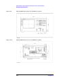
Names and Functions of Parts on the Front Panel . . . . . . . . . . . . . . . . . . . . . . . . . . . . . . . . . . . . . . . . . . . .
1. Stand-by switch () . . . . . . . . . . . . . . . . . . . . . . . . . . . . . . . . . . . . . . . . . . . . . . . . . . . . . . . . . . . . . . . . .
2. Built-in 3.5-inch floppy disk drive . . . . . . . . . . . . . . . . . . . . . . . . . . . . . . . . . . . . . . . . . . . . . . . . . . . .
3. Color LCD display . . . . . . . . . . . . . . . . . . . . . . . . . . . . . . . . . . . . . . . . . . . . . . . . . . . . . . . . . . . . . . . .
4. Navigation block (NAVIGATION). . . . . . . . . . . . . . . . . . . . . . . . . . . . . . . . . . . . . . . . . . . . . . . . . . . .
5. Measurement block (MEASUREMENT). . . . . . . . . . . . . . . . . . . . . . . . . . . . . . . . . . . . . . . . . . . . . . .
6. Instrument state block (INSTR STATE) . . . . . . . . . . . . . . . . . . . . . . . . . . . . . . . . . . . . . . . . . . . . . . . .
7. Entry block (ENTRY) . . . . . . . . . . . . . . . . . . . . . . . . . . . . . . . . . . . . . . . . . . . . . . . . . . . . . . . . . . . . . .
8. Test Head Interface (TEST HEAD INTERFACE) . . . . . . . . . . . . . . . . . . . . . . . . . . . . . . . . . . . . . . . .
Names and Functions of Parts on the Rear Panel. . . . . . . . . . . . . . . . . . . . . . . . . . . . . . . . . . . . . . . . . . . . .
1. Power cable receptacle (- LINE) . . . . . . . . . . . . . . . . . . . . . . . . . . . . . . . . . . . . . . . . . . . . . . . . . . . . .
2. External trigger input terminal (Ext Trig). . . . . . . . . . . . . . . . . . . . . . . . . . . . . . . . . . . . . . . . . . . . . . .
3. External monitor output terminal (VIDEO) . . . . . . . . . . . . . . . . . . . . . . . . . . . . . . . . . . . . . . . . . . . . .
4. LAN port. . . . . . . . . . . . . . . . . . . . . . . . . . . . . . . . . . . . . . . . . . . . . . . . . . . . . . . . . . . . . . . . . . . . . . . .
5. GPIB connector. . . . . . . . . . . . . . . . . . . . . . . . . . . . . . . . . . . . . . . . . . . . . . . . . . . . . . . . . . . . . . . . . . .
6. Handler interface. . . . . . . . . . . . . . . . . . . . . . . . . . . . . . . . . . . . . . . . . . . . . . . . . . . . . . . . . . . . . . . . . .
7. External reference signal input terminal (Ext Ref In, 10 MHz 0 dBm) . . . . . . . . . . . . . . . . . . . . . . . .
8. Internal reference signal output terminal (Int Ref Out) . . . . . . . . . . . . . . . . . . . . . . . . . . . . . . . . . . . .
9. Mouse port (MOUSE) . . . . . . . . . . . . . . . . . . . . . . . . . . . . . . . . . . . . . . . . . . . . . . . . . . . . . . . . . . . . .
10. Mini-DIN keyboard port (KYBD) . . . . . . . . . . . . . . . . . . . . . . . . . . . . . . . . . . . . . . . . . . . . . . . . . . .
11. Serial number plate . . . . . . . . . . . . . . . . . . . . . . . . . . . . . . . . . . . . . . . . . . . . . . . . . . . . . . . . . . . . . . .
12. Option plate. . . . . . . . . . . . . . . . . . . . . . . . . . . . . . . . . . . . . . . . . . . . . . . . . . . . . . . . . . . . . . . . . . . . .
13. Reserved ports (Reserved) . . . . . . . . . . . . . . . . . . . . . . . . . . . . . . . . . . . . . . . . . . . . . . . . . . . . . . . . .
Names and Functions of Display Areas on the LCD Display . . . . . . . . . . . . . . . . . . . . . . . . . . . . . . . . . . .
Single point measurement display . . . . . . . . . . . . . . . . . . . . . . . . . . . . . . . . . . . . . . . . . . . . . . . . . . . . . .
List measurement display . . . . . . . . . . . . . . . . . . . . . . . . . . . . . . . . . . . . . . . . . . . . . . . . . . . . . . . . . . . . .
Measurement point setup display . . . . . . . . . . . . . . . . . . . . . . . . . . . . . . . . . . . . . . . . . . . . . . . . . . . . . . .
Calibration kit setup display . . . . . . . . . . . . . . . . . . . . . . . . . . . . . . . . . . . . . . . . . . . . . . . . . . . . . . . . . . .
Compensation kit setup display . . . . . . . . . . . . . . . . . . . . . . . . . . . . . . . . . . . . . . . . . . . . . . . . . . . . . . . .
Bin sorting setup display. . . . . . . . . . . . . . . . . . . . . . . . . . . . . . . . . . . . . . . . . . . . . . . . . . . . . . . . . . . . . .
4287A Key Operation Overview . . . . . . . . . . . . . . . . . . . . . . . . . . . . . . . . . . . . . . . . . . . . . . . . . . . . . . . . .
74
74
74
75
75
75
76
76
77
79
79
79
80
80
80
80
80
80
80
81
81
81
81
82
84
89
91
93
95
97
99
5. Setting Measurement Conditions
How to Preset the 4287A . . . . . . . . . . . . . . . . . . . . . . . . . . . . . . . . . . . . . . . . . . . . . . . . . . . . . . . . . . . . . . 102
10
Contents
How to Set the Measurement Point . . . . . . . . . . . . . . . . . . . . . . . . . . . . . . . . . . . . . . . . . . . . . . . . . . . . . . 103
How to bring up the measurement point setup display . . . . . . . . . . . . . . . . . . . . . . . . . . . . . . . . . . . . . . 103
How to specify table number for setup . . . . . . . . . . . . . . . . . . . . . . . . . . . . . . . . . . . . . . . . . . . . . . . . . . 104
How to add measurement points . . . . . . . . . . . . . . . . . . . . . . . . . . . . . . . . . . . . . . . . . . . . . . . . . . . . . . . 105
How to change frequency of a set measurement point . . . . . . . . . . . . . . . . . . . . . . . . . . . . . . . . . . . . . . 108
How to change averaging factor . . . . . . . . . . . . . . . . . . . . . . . . . . . . . . . . . . . . . . . . . . . . . . . . . . . . . . . 109
How to change oscillator level . . . . . . . . . . . . . . . . . . . . . . . . . . . . . . . . . . . . . . . . . . . . . . . . . . . . . . . . 110
How to change oscillator level setup unit . . . . . . . . . . . . . . . . . . . . . . . . . . . . . . . . . . . . . . . . . . . . . . . . 111
Setting up dc resistance (Rdc) measurement . . . . . . . . . . . . . . . . . . . . . . . . . . . . . . . . . . . . . . . . . . . . . . . 113
Turning ON/OFF . . . . . . . . . . . . . . . . . . . . . . . . . . . . . . . . . . . . . . . . . . . . . . . . . . . . . . . . . . . . . . . . . . . 113
Turning ON/OFF offset cancel function . . . . . . . . . . . . . . . . . . . . . . . . . . . . . . . . . . . . . . . . . . . . . . . . . 113
6. Calibration and Compensation
Calibration and Compensation Functions. . . . . . . . . . . . . . . . . . . . . . . . . . . . . . . . . . . . . . . . . . . . . . . . . . 116
Types of calibration and compensation functions . . . . . . . . . . . . . . . . . . . . . . . . . . . . . . . . . . . . . . . . . . 116
Calibration reference plane and required calibration and compensation . . . . . . . . . . . . . . . . . . . . . . . . 117
Calibration and Compensation Procedures Using Dedicated Test Fixture. . . . . . . . . . . . . . . . . . . . . . . . . 120
1. Test head coaxial terminal used as calibration reference plane . . . . . . . . . . . . . . . . . . . . . . . . . . . . . 121
2. DUT connection terminal used as calibration reference plane . . . . . . . . . . . . . . . . . . . . . . . . . . . . . . 131
Calibration and Compensation Procedure without Using Dedicated Test Fixture . . . . . . . . . . . . . . . . . . . 135
1. Test head coaxial terminal used as calibration reference plane. . . . . . . . . . . . . . . . . . . . . . . . . . . . . . 135
2. DUT connection terminal used as calibration reference plane . . . . . . . . . . . . . . . . . . . . . . . . . . . . . . 142
How to Define Calibration Kit . . . . . . . . . . . . . . . . . . . . . . . . . . . . . . . . . . . . . . . . . . . . . . . . . . . . . . . . . . 145
Calibration kit definition procedure . . . . . . . . . . . . . . . . . . . . . . . . . . . . . . . . . . . . . . . . . . . . . . . . . . . . 145
How to Define Compensation Kit . . . . . . . . . . . . . . . . . . . . . . . . . . . . . . . . . . . . . . . . . . . . . . . . . . . . . . . 147
Compensation kit definition procedure . . . . . . . . . . . . . . . . . . . . . . . . . . . . . . . . . . . . . . . . . . . . . . . . . . 147
Registering the Electrical Length of Unregistered Test Fixtures . . . . . . . . . . . . . . . . . . . . . . . . . . . . . . . . 149
Preventing Mistakes During Execution of Calibration and Compensation . . . . . . . . . . . . . . . . . . . . . . . . 151
1. Setting the limit for DC resistance (Rdc) . . . . . . . . . . . . . . . . . . . . . . . . . . . . . . . . . . . . . . . . . . . . . . 151
2. How to execute calibration and compensation . . . . . . . . . . . . . . . . . . . . . . . . . . . . . . . . . . . . . . . . . . 152
7. Executing Measurements and Displaying Results
Connecting the DUT . . . . . . . . . . . . . . . . . . . . . . . . . . . . . . . . . . . . . . . . . . . . . . . . . . . . . . . . . . . . . . . . . . 156
Selecting Single Point Measurement or List Measurement . . . . . . . . . . . . . . . . . . . . . . . . . . . . . . . . . . . . 157
How to Select the Measurement Point Table . . . . . . . . . . . . . . . . . . . . . . . . . . . . . . . . . . . . . . . . . . . . . . . 158
Selection of Measurement Point . . . . . . . . . . . . . . . . . . . . . . . . . . . . . . . . . . . . . . . . . . . . . . . . . . . . . . . . . 159
Selection of Measurement Parameters in Single Point Measurement Display. . . . . . . . . . . . . . . . . . . . . . 160
Selection of Display Parameters in List Measurement Display . . . . . . . . . . . . . . . . . . . . . . . . . . . . . . . . . 162
Setting How the Instrument Displays Measurement Results (Enabling/Disabling Deviation Measurement
Mode) . . . . . . . . . . . . . . . . . . . . . . . . . . . . . . . . . . . . . . . . . . . . . . . . . . . . . . . . . . . . . . . . . . . . . . . . . . . . . 164
Hiding the Screen Display . . . . . . . . . . . . . . . . . . . . . . . . . . . . . . . . . . . . . . . . . . . . . . . . . . . . . . . . . . . . . 166
Turning ON/OFF Update the LCD Display View . . . . . . . . . . . . . . . . . . . . . . . . . . . . . . . . . . . . . . . . . . . 167
8. Sorting According to Measurement Results
Overview of BIN Sort Function . . . . . . . . . . . . . . . . . . . . . . . . . . . . . . . . . . . . . . . . . . . . . . . . . . . . . . . . . 172
Concept of setting 4287A BINs . . . . . . . . . . . . . . . . . . . . . . . . . . . . . . . . . . . . . . . . . . . . . . . . . . . . . . . 174
Internal flow of BIN sort judgment. . . . . . . . . . . . . . . . . . . . . . . . . . . . . . . . . . . . . . . . . . . . . . . . . . . . . 176
Setting Measurement Point . . . . . . . . . . . . . . . . . . . . . . . . . . . . . . . . . . . . . . . . . . . . . . . . . . . . . . . . . . . . . 177
11
Contents
Setting Measurement Parameter. . . . . . . . . . . . . . . . . . . . . . . . . . . . . . . . . . . . . . . . . . . . . . . . . . . . . . . . .
Setting Limit Mode and Reference Value . . . . . . . . . . . . . . . . . . . . . . . . . . . . . . . . . . . . . . . . . . . . . . . . .
Setting limit mode. . . . . . . . . . . . . . . . . . . . . . . . . . . . . . . . . . . . . . . . . . . . . . . . . . . . . . . . . . . . . . . . . .
Setting reference value . . . . . . . . . . . . . . . . . . . . . . . . . . . . . . . . . . . . . . . . . . . . . . . . . . . . . . . . . . . . . .
Setting BIN Range . . . . . . . . . . . . . . . . . . . . . . . . . . . . . . . . . . . . . . . . . . . . . . . . . . . . . . . . . . . . . . . . . . .
Setting upper limit value. . . . . . . . . . . . . . . . . . . . . . . . . . . . . . . . . . . . . . . . . . . . . . . . . . . . . . . . . . . . .
Setting lower limit value. . . . . . . . . . . . . . . . . . . . . . . . . . . . . . . . . . . . . . . . . . . . . . . . . . . . . . . . . . . . .
Selecting BIN range mode . . . . . . . . . . . . . . . . . . . . . . . . . . . . . . . . . . . . . . . . . . . . . . . . . . . . . . . . . . .
Setting BIN On and Off . . . . . . . . . . . . . . . . . . . . . . . . . . . . . . . . . . . . . . . . . . . . . . . . . . . . . . . . . . . . . . .
Setting Faulty BIN (OUT OF GOOD BINS) . . . . . . . . . . . . . . . . . . . . . . . . . . . . . . . . . . . . . . . . . . . . . . .
Setting Upper and Lower Limit Values for DC Resistance Measurement. . . . . . . . . . . . . . . . . . . . . . . . .
Turning On BIN Sorting and Displaying the Result . . . . . . . . . . . . . . . . . . . . . . . . . . . . . . . . . . . . . . . . .
Bin Count Function . . . . . . . . . . . . . . . . . . . . . . . . . . . . . . . . . . . . . . . . . . . . . . . . . . . . . . . . . . . . . . . . . .
Turning on Bin Count . . . . . . . . . . . . . . . . . . . . . . . . . . . . . . . . . . . . . . . . . . . . . . . . . . . . . . . . . . . . . . .
Listing the BIN Count results . . . . . . . . . . . . . . . . . . . . . . . . . . . . . . . . . . . . . . . . . . . . . . . . . . . . . . . . .
Initializing the contents of the bin counts to zero (resetting the counter). . . . . . . . . . . . . . . . . . . . . . . .
Example of Settings for BIN Sorting . . . . . . . . . . . . . . . . . . . . . . . . . . . . . . . . . . . . . . . . . . . . . . . . . . . . .
Setting the measurement point number, measurement parameter, and BIN range setting mode for
Condition 1 . . . . . . . . . . . . . . . . . . . . . . . . . . . . . . . . . . . . . . . . . . . . . . . . . . . . . . . . . . . . . . . . . . . . . . .
Setting the measurement point number, measurement parameter, and BIN range setting mode for
Condition 2 . . . . . . . . . . . . . . . . . . . . . . . . . . . . . . . . . . . . . . . . . . . . . . . . . . . . . . . . . . . . . . . . . . . . . . .
Setting the measurement value range for sorting into BIN 1 to BIN 3 . . . . . . . . . . . . . . . . . . . . . . . . .
OUT OF GOOD BINS setting . . . . . . . . . . . . . . . . . . . . . . . . . . . . . . . . . . . . . . . . . . . . . . . . . . . . . . . .
Displaying the BIN sorting results . . . . . . . . . . . . . . . . . . . . . . . . . . . . . . . . . . . . . . . . . . . . . . . . . . . . .
179
181
181
182
183
183
184
185
186
187
188
189
190
190
190
191
192
193
196
197
202
204
9. Obtaining Statistical Data on Measurement Results
Overview of Functions for Statistical Analysis . . . . . . . . . . . . . . . . . . . . . . . . . . . . . . . . . . . . . . . . . . . . .
Data Logging for Statistical Analysis. . . . . . . . . . . . . . . . . . . . . . . . . . . . . . . . . . . . . . . . . . . . . . . . . . . . .
Executing Statistical Analysis and Displaying Results . . . . . . . . . . . . . . . . . . . . . . . . . . . . . . . . . . . . . . .
Saving Measurement Data for Statistical Analysis . . . . . . . . . . . . . . . . . . . . . . . . . . . . . . . . . . . . . . . . . .
206
207
209
210
10. Storing and Retrieving 4287A Internal Information and File Management
Saving Setting Status . . . . . . . . . . . . . . . . . . . . . . . . . . . . . . . . . . . . . . . . . . . . . . . . . . . . . . . . . . . . . . . . .
Entering the Filename using the Mouse . . . . . . . . . . . . . . . . . . . . . . . . . . . . . . . . . . . . . . . . . . . . . . . . .
Saving Screen Displays . . . . . . . . . . . . . . . . . . . . . . . . . . . . . . . . . . . . . . . . . . . . . . . . . . . . . . . . . . . . . . .
Saving the List Measurement Display in CSV Format . . . . . . . . . . . . . . . . . . . . . . . . . . . . . . . . . . . . . . .
Example of the Saved List Measurement Display Data (CSV format) . . . . . . . . . . . . . . . . . . . . . . . . .
Saving the Setup Table (Measurement point, Calibration kit, Compensation kit) in CSV Format . . . . . .
Example of the Saved Setup Table Data (CSV format) . . . . . . . . . . . . . . . . . . . . . . . . . . . . . . . . . . . . .
Saving the BIN Sorting Setup Table in CSV Format . . . . . . . . . . . . . . . . . . . . . . . . . . . . . . . . . . . . . . . . .
Example of the Saved BIN Sorting Setup Table Data (CSV format) . . . . . . . . . . . . . . . . . . . . . . . . . . .
214
215
216
217
218
219
220
221
222
11. Setting and Using the Control and Management Facilities
Checking and Editing the GPIB Address . . . . . . . . . . . . . . . . . . . . . . . . . . . . . . . . . . . . . . . . . . . . . . . . . .
Configuring the Network . . . . . . . . . . . . . . . . . . . . . . . . . . . . . . . . . . . . . . . . . . . . . . . . . . . . . . . . . . . . . .
Enabling/disabling network . . . . . . . . . . . . . . . . . . . . . . . . . . . . . . . . . . . . . . . . . . . . . . . . . . . . . . . . . .
Setting IP address . . . . . . . . . . . . . . . . . . . . . . . . . . . . . . . . . . . . . . . . . . . . . . . . . . . . . . . . . . . . . . . . . .
Specifying computer name . . . . . . . . . . . . . . . . . . . . . . . . . . . . . . . . . . . . . . . . . . . . . . . . . . . . . . . . . . .
226
228
228
229
231
12
Contents
Setting the Built-in Speaker (Beep Sound). . . . . . . . . . . . . . . . . . . . . . . . . . . . . . . . . . . . . . . . . . . . . . . . . 233
Turning the completion beep ON or OFF . . . . . . . . . . . . . . . . . . . . . . . . . . . . . . . . . . . . . . . . . . . . . . . . 233
Turning the warning beep ON or OFF . . . . . . . . . . . . . . . . . . . . . . . . . . . . . . . . . . . . . . . . . . . . . . . . . . 233
Switching the beep sound that indicates the BIN sort function result (Pass or Fail) . . . . . . . . . . . . . . . 234
Locking the Front Panel Keys, Keyboard and Mouse . . . . . . . . . . . . . . . . . . . . . . . . . . . . . . . . . . . . . . . . 235
Locking the front panel keys and keyboad . . . . . . . . . . . . . . . . . . . . . . . . . . . . . . . . . . . . . . . . . . . . . . . 235
Locking the keyboard . . . . . . . . . . . . . . . . . . . . . . . . . . . . . . . . . . . . . . . . . . . . . . . . . . . . . . . . . . . . . . . 236
Locking the mouse . . . . . . . . . . . . . . . . . . . . . . . . . . . . . . . . . . . . . . . . . . . . . . . . . . . . . . . . . . . . . . . . . 237
Locking the front panel keys, keyboard and mouse simultaneously. . . . . . . . . . . . . . . . . . . . . . . . . . . . 238
Turning OFF the LCD Display’s Backlight . . . . . . . . . . . . . . . . . . . . . . . . . . . . . . . . . . . . . . . . . . . . . . . . 239
System Recovery . . . . . . . . . . . . . . . . . . . . . . . . . . . . . . . . . . . . . . . . . . . . . . . . . . . . . . . . . . . . . . . . . . . . 240
Types of system recoveries . . . . . . . . . . . . . . . . . . . . . . . . . . . . . . . . . . . . . . . . . . . . . . . . . . . . . . . . . . . 240
Notes on executing system recovery . . . . . . . . . . . . . . . . . . . . . . . . . . . . . . . . . . . . . . . . . . . . . . . . . . . 240
Procedure to execute system recovery . . . . . . . . . . . . . . . . . . . . . . . . . . . . . . . . . . . . . . . . . . . . . . . . . . 241
Procedure to create the user backup image . . . . . . . . . . . . . . . . . . . . . . . . . . . . . . . . . . . . . . . . . . . . . . . 244
Procedure to execute the user recovery function . . . . . . . . . . . . . . . . . . . . . . . . . . . . . . . . . . . . . . . . . . 247
12. Specifications and Supplemental Performance Characteristics
Basic Measurement Characteristics . . . . . . . . . . . . . . . . . . . . . . . . . . . . . . . . . . . . . . . . . . . . . . . . . . . . . . 253
Measurement parameters. . . . . . . . . . . . . . . . . . . . . . . . . . . . . . . . . . . . . . . . . . . . . . . . . . . . . . . . . . . . . 253
Measurement range . . . . . . . . . . . . . . . . . . . . . . . . . . . . . . . . . . . . . . . . . . . . . . . . . . . . . . . . . . . . . . . . . 253
Source characteristics . . . . . . . . . . . . . . . . . . . . . . . . . . . . . . . . . . . . . . . . . . . . . . . . . . . . . . . . . . . . . . . 253
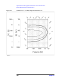
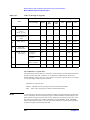
Measurement accuracy . . . . . . . . . . . . . . . . . . . . . . . . . . . . . . . . . . . . . . . . . . . . . . . . . . . . . . . . . . . . . . 255
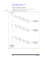
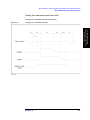
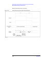
Timing chart and measurement time (SPC) . . . . . . . . . . . . . . . . . . . . . . . . . . . . . . . . . . . . . . . . . . . . . . 261
Measurement Support Functions . . . . . . . . . . . . . . . . . . . . . . . . . . . . . . . . . . . . . . . . . . . . . . . . . . . . . . . . 270
Error correction function . . . . . . . . . . . . . . . . . . . . . . . . . . . . . . . . . . . . . . . . . . . . . . . . . . . . . . . . . . . . . 270
DC resistance (Rdc) measurement . . . . . . . . . . . . . . . . . . . . . . . . . . . . . . . . . . . . . . . . . . . . . . . . . . . . . 270
Trigger function. . . . . . . . . . . . . . . . . . . . . . . . . . . . . . . . . . . . . . . . . . . . . . . . . . . . . . . . . . . . . . . . . . . . 271
Averaging function . . . . . . . . . . . . . . . . . . . . . . . . . . . . . . . . . . . . . . . . . . . . . . . . . . . . . . . . . . . . . . . . . 271
Display . . . . . . . . . . . . . . . . . . . . . . . . . . . . . . . . . . . . . . . . . . . . . . . . . . . . . . . . . . . . . . . . . . . . . . . . . . 271
List measurement function . . . . . . . . . . . . . . . . . . . . . . . . . . . . . . . . . . . . . . . . . . . . . . . . . . . . . . . . . . . 271
Test signal level monitor function . . . . . . . . . . . . . . . . . . . . . . . . . . . . . . . . . . . . . . . . . . . . . . . . . . . . . . 271
Mass Storage . . . . . . . . . . . . . . . . . . . . . . . . . . . . . . . . . . . . . . . . . . . . . . . . . . . . . . . . . . . . . . . . . . . . . . 271
Interface. . . . . . . . . . . . . . . . . . . . . . . . . . . . . . . . . . . . . . . . . . . . . . . . . . . . . . . . . . . . . . . . . . . . . . . . . . 271
Measurement terminal (at Test Head) . . . . . . . . . . . . . . . . . . . . . . . . . . . . . . . . . . . . . . . . . . . . . . . . . . . 273
Rear panel connectors . . . . . . . . . . . . . . . . . . . . . . . . . . . . . . . . . . . . . . . . . . . . . . . . . . . . . . . . . . . . . . . 273
General Characteristics . . . . . . . . . . . . . . . . . . . . . . . . . . . . . . . . . . . . . . . . . . . . . . . . . . . . . . . . . . . . . . . . 275
Environment conditions . . . . . . . . . . . . . . . . . . . . . . . . . . . . . . . . . . . . . . . . . . . . . . . . . . . . . . . . . . . . . 275
Furnished accessories . . . . . . . . . . . . . . . . . . . . . . . . . . . . . . . . . . . . . . . . . . . . . . . . . . . . . . . . . . . . . . . 280
Option 004 Working Standard Set Characteristics . . . . . . . . . . . . . . . . . . . . . . . . . . . . . . . . . . . . . . . . . . . 281
Furnished devices . . . . . . . . . . . . . . . . . . . . . . . . . . . . . . . . . . . . . . . . . . . . . . . . . . . . . . . . . . . . . . . . . . 281
DC resistance. . . . . . . . . . . . . . . . . . . . . . . . . . . . . . . . . . . . . . . . . . . . . . . . . . . . . . . . . . . . . . . . . . . . . . 281
A. Manual Changes
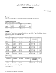
Manual Changes . . . . . . . . . . . . . . . . . . . . . . . . . . . . . . . . . . . . . . . . . . . . . . . . . . . . . . . . . . . . . . . . . . . . . 284
Change 7 . . . . . . . . . . . . . . . . . . . . . . . . . . . . . . . . . . . . . . . . . . . . . . . . . . . . . . . . . . . . . . . . . . . . . . . . . 285
Change 6 . . . . . . . . . . . . . . . . . . . . . . . . . . . . . . . . . . . . . . . . . . . . . . . . . . . . . . . . . . . . . . . . . . . . . . . . . 285
Change 5 . . . . . . . . . . . . . . . . . . . . . . . . . . . . . . . . . . . . . . . . . . . . . . . . . . . . . . . . . . . . . . . . . . . . . . . . . 287
13
Contents
Change 4 . . . . . . . . . . . . . . . . . . . . . . . . . . . . . . . . . . . . . . . . . . . . . . . . . . . . . . . . . . . . . . . . . . . . . . . . .
Miscellaneous Changes. . . . . . . . . . . . . . . . . . . . . . . . . . . . . . . . . . . . . . . . . . . . . . . . . . . . . . . . . . . . . .
Change 3 . . . . . . . . . . . . . . . . . . . . . . . . . . . . . . . . . . . . . . . . . . . . . . . . . . . . . . . . . . . . . . . . . . . . . . . . .
Change 2 . . . . . . . . . . . . . . . . . . . . . . . . . . . . . . . . . . . . . . . . . . . . . . . . . . . . . . . . . . . . . . . . . . . . . . . . .
Change 1 . . . . . . . . . . . . . . . . . . . . . . . . . . . . . . . . . . . . . . . . . . . . . . . . . . . . . . . . . . . . . . . . . . . . . . . . .
288
291
293
293
293
B. Differences from Agilent 4286A
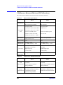
1. Main Differences Between 4286A and 4287A. . . . . . . . . . . . . . . . . . . . . . . . . . . . . . . . . . . . . . . . . . . .
Outline of Differences in Calibration/Compensation . . . . . . . . . . . . . . . . . . . . . . . . . . . . . . . . . . . . . . .
Outline of Differences in Comparator Handler I/F. . . . . . . . . . . . . . . . . . . . . . . . . . . . . . . . . . . . . . . . .
Other Important Differences . . . . . . . . . . . . . . . . . . . . . . . . . . . . . . . . . . . . . . . . . . . . . . . . . . . . . . . . . .
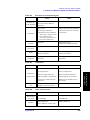
2. Differences Between 4286A and 4287A Hardware . . . . . . . . . . . . . . . . . . . . . . . . . . . . . . . . . . . . . . . .
3. Functional Differences Between 4286A and 4287A . . . . . . . . . . . . . . . . . . . . . . . . . . . . . . . . . . . . . . .
296
296
297
297
298
301
C. Improvement of Measurement Throughput by Screen Display Settings
How to improve 4287A measurement throughput by screen display settings . . . . . . . . . . . . . . . . . . . . . . 310
Hiding the Screen Display . . . . . . . . . . . . . . . . . . . . . . . . . . . . . . . . . . . . . . . . . . . . . . . . . . . . . . . . . . . 310
Optimizing the Settings of the Display Contents . . . . . . . . . . . . . . . . . . . . . . . . . . . . . . . . . . . . . . . . . . 310
D. Table of Operations When Measurement Errors Occur
Operations When Measurement Errors Occur . . . . . . . . . . . . . . . . . . . . . . . . . . . . . . . . . . . . . . . . . . . . . . 312
E. Printing Out Measurement Results and Internal Data on a Printer
Printer Support . . . . . . . . . . . . . . . . . . . . . . . . . . . . . . . . . . . . . . . . . . . . . . . . . . . . . . . . . . . . . . . . . . . . . .
Printer Support . . . . . . . . . . . . . . . . . . . . . . . . . . . . . . . . . . . . . . . . . . . . . . . . . . . . . . . . . . . . . . . . . . . . . .
Procedure for Printing . . . . . . . . . . . . . . . . . . . . . . . . . . . . . . . . . . . . . . . . . . . . . . . . . . . . . . . . . . . . . . . .
1. Selecting the contents to be printed . . . . . . . . . . . . . . . . . . . . . . . . . . . . . . . . . . . . . . . . . . . . . . . . . .
2. Setting the image format. . . . . . . . . . . . . . . . . . . . . . . . . . . . . . . . . . . . . . . . . . . . . . . . . . . . . . . . . . .
3. Setting paper orientation . . . . . . . . . . . . . . . . . . . . . . . . . . . . . . . . . . . . . . . . . . . . . . . . . . . . . . . . . . .
4. Selecting the printer model . . . . . . . . . . . . . . . . . . . . . . . . . . . . . . . . . . . . . . . . . . . . . . . . . . . . . . . . .
5. Starting and stopping printing. . . . . . . . . . . . . . . . . . . . . . . . . . . . . . . . . . . . . . . . . . . . . . . . . . . . . . .
314
315
316
316
316
317
317
318
F. Error Messages
Order of Error Number. . . . . . . . . . . . . . . . . . . . . . . . . . . . . . . . . . . . . . . . . . . . . . . . . . . . . . . . . . . . . . . . 320
G. Information on Maintenance
Cleaning this Instrument. . . . . . . . . . . . . . . . . . . . . . . . . . . . . . . . . . . . . . . . . . . . . . . . . . . . . . . . . . . . . . .
Cleaning an LCD . . . . . . . . . . . . . . . . . . . . . . . . . . . . . . . . . . . . . . . . . . . . . . . . . . . . . . . . . . . . . . . . . .
Maintenance of Connectors/Ports . . . . . . . . . . . . . . . . . . . . . . . . . . . . . . . . . . . . . . . . . . . . . . . . . . . . . .
Cleaning a Display Other than an LCD . . . . . . . . . . . . . . . . . . . . . . . . . . . . . . . . . . . . . . . . . . . . . . . . .
Cautions Applicable to Requesting Repair, Replacement, Regular Calibration, etc. . . . . . . . . . . . . . . . .
Devices to be Sent Back for Repair or Regular Calibration . . . . . . . . . . . . . . . . . . . . . . . . . . . . . . . . . .
Recommended Calibration Period . . . . . . . . . . . . . . . . . . . . . . . . . . . . . . . . . . . . . . . . . . . . . . . . . . . . .
14
330
330
330
332
333
333
333
1. How to Use This
Operation Manual
1
How to Use This Operation Manual
This chapter explains how to most efficiently use this Operation Manual.
15
How to Use This Operation Manual
Relationship of Operation Manual Contents to the Handling of the 4287A
Relationship of Operation Manual Contents to the Handling
of the 4287A
The chapters of this Operation Manual cover the usage flow from when the product is
delivered until when the user has obtained sufficient understanding of the instrument’s
functions to use it efficiently.
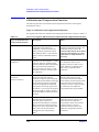
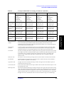
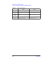
Table 1-1
Relationship of Operation Manual Contents to Handling the 4287A
Handling of 4287A
Corresponding Chapter in Operation Manual
1. Installation
Chapter 2 “Installation Guide” on page 17
2. Understanding functions
Chapter 3 “Learning Basic Operations” on page 49
Chapter 4 “Function Overview” on page 73*1
3. Performing measurements (manual
operation)
Chapter 5 “Setting Measurement Conditions” on page 101
Chapter 6 “Calibration and Compensation” on page 115
Chapter 7 “Executing Measurements and Displaying Results” on
page 155
4. Using analysis functions (manual
operation)
Chapter 8 “Sorting According to Measurement Results” on
page 171
Chapter 9 “Obtaining Statistical Data on Measurement Results”
on page 205
Chapter 10 “Storing and Retrieving 4287A Internal Information
and File Management” on page 213
5. Using control and management facilities
(manual operation)
Chapter 11 “Setting and Using the Control and Management
Facilities” on page 225
6. Development of automatic measurement
system
(this entire manual and the Programming Manual)
*1.If you need more detailed information, please refer to Chapter 12, “Specifications and Supplemental Performance
Characteristics,” on page 251.
16
Chapter 1
2. Installation Guide
2
Installation Guide
This chapter describes procedures for preparing the Agilent 4287A RF LCR meter for use
after it is delivered. It also describes daily maintenance procedures.
17
Installation Guide
Incoming Inspection
Incoming Inspection
WARNING
To avoid hazardous electrical shock, do not turn the power on if there are any signs of
shipping damage to any part of the exterior (for example, damage on the top cover,
bottom cover, side covers, front panel, rear panel, LCD display, connectors or line
switch).
Inspect the equipment by following these steps while unpacking the contents of the
shipping container.
Step 1. Check whether the shipping container or cushioning material is damaged.
If there is damage, save the shipping container and cushioning material as they are until
you have made sure that all contents (main unit and accessories) are included and you have
checked for mechanical and electrical defects.
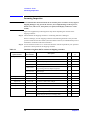
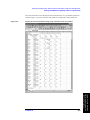
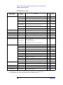
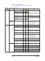
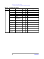
Step 2. Use the checklist in Table 2-1 to ensure that all of the contents required for your specified
options have been packed in the shipping container.
Table 2-1
Checklist of Agilent 4287A contents in shipping container
Order Model or
Option Number
Agilent
Part Number
Agilent 4287A
-
Agilent 4287A RF LCR Meter (Main Unit)
1
-
Test Head (with 1 m cable)
1
1250-2879
N(m)-SMA(f) Adapter
3
8710-2409
Wrench (for 3.5-mm/SMA connector)
1
04287-905xx
CD-ROM (Operation Manual,
Programming Manual, Sample Program)*1
1
E2078-62101
GPIB adapter*2
1
-
Power Cable
1
Option 700
-
Agilent 16195B 7-mm Calibration Kit
1
Option 710
-
Test Fixture Stand
1
Option 720
1250-1746
3.5-mm-to-7-mm Coaxial Adapter
1
Option 810
-
Keyboard
1
Option 820
-
Mouse
1
Option ABA
04287-900x0
Operation Manual*1
1
04287-900x1
Programming Manual*1
1
04287-180x0
Sample Program Disk (3.5 inch floppy disk)*1
1
18
Description
Qty
Check
(√)
Chapter 2
Installation Guide
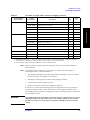
Incoming Inspection
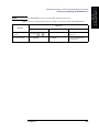
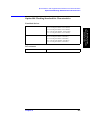
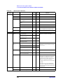
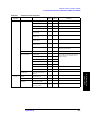
Table 2-1
Checklist of Agilent 4287A contents in shipping container
Agilent
Part Number
Option 004
16197-29001
Short device 0.6 × 0.3 mm
2
16191-29005
Short device 1.0 × 0.5 mm
2
16191-29006
Short device 1.6 × 0.8 mm
2
16191-29007
Short device 2.0 × 1.25 mm
2
16191-29008
Short device 3.2 × 1.6 mm
2
0699-6926
Resistor 0.6 × 0.3 mm
5
5182-0433
Resistor 1.0 × 0.5 mm
5
5182-0434
Resistor 1.6 × 0.8 mm
5
5182-0435
Resistor 2.0 × 1.25 mm
5
5182-0436
Resistor 3.2 × 1.6 mm
5
Test Head Extension Cable (1 m)
1
1250-1158
SMA(f)–SMA(f) Adapter
3
Option 1CM
5063-9216
Rackmount Kit
1
Option 1CN
5063-9229
Handle Kit
1
Option 1CP
5188-4430
Rackmount & Handle Kit
1
Option 020
-
Description
Qty
Check
(√)
2. Installation Guide
Order Model or
Option Number
*1. The number indicated by “x” in the part number of each manual or sample program disk, 0 for the first edition, is
incremented by 1 each time a revision is made. The latest edition comes with the product.
*2. Use this adapter when to connect a GPIB cable to 4287A GPIB connector.
Step 3. Make sure that the contents (main unit and accessories) are free of any mechanical or
electrical defect.
Step 4. If you find any of the following in your inspection, contact your nearest Agilent
Technologies office or sales representative:
1. The equipment packaging and cushioning material are damaged, or there is evidence
that excessive force was applied to the container
2. Something is missing from the contents of the shipping container
3. A mechanical or electrical defect is found
4. Failure occurs during verification of equipment operation
In the case of 1, contact the forwarding agent of the equipment as well as your nearest
Agilent Technologies office or sales representative. For subsequent inspection by the
forwarding agent, the equipment, the shipping container, cushioning material, and contents
must be kept as they are.
WARNING
To avoid hazardous electrical shock, do not turn the power on if there are any signs of
shipping damage to any part of the exterior (for example, damage on the top cover,
bottom cover, side covers, front panel, rear panel, LCD display, connectors or line
switch).
Chapter 2
19
Installation Guide
Environmental Requirements
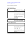
Environmental Requirements
Ensure that the following environmental requirements are met before using this equipment.
Operation environment
Use the equipment in the following environment:
Environmental requirements
Temperature
5 °C to 40 °C
Relative
humidity
20 % to 80 %, wet bulb temperature ≤ 29 °C (disk drive*1 operating
condition)
15 % to 90 %, wet bulb temperature ≤ 29 °C (disk drive *1
non-operating condition)
Altitude
0 to 2,000 m (0 to 6,561 feet)
*1. Built-in floppy disk
NOTE
Do not use the equipment in environments where condensation may occur.
For the environmental requirements of the equipment’s storage, see “Environment
conditions” on page 275.
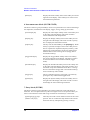
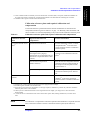
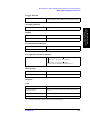
Ventilation space at installation site
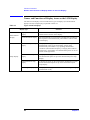
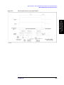
To ensure the specifications and measurement accuracy of the product, you must keep
ambient temperature around the product within the specified range by providing
appropriate cooling clearance around the product or, for the rackmount type, by forcefully
air-cooling inside the rack housing. For information on ambient temperature to satisfy the
specifications and measurement accuracy of the product, refer to “Measurement accuracy”
on page 255 in Chapter 12, “Specifications and Supplemental Performance
Characteristics.”
When the ambient temperature around the product is kept within the temperature range of
the operating environment specification (refer to “Operating Condition” on page 275), the
product conforms to the requirements of the safety standard. Furthermore, under that
temperature environment, it has been confirmed that the product still conforms to the
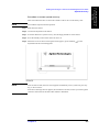
requirements of the safety standard when it is enclosed with cooling clearance as follows:
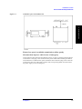
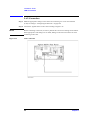
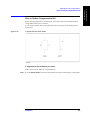
Requirements
Back
≥ 180 mm
Sides
≥ 60 mm (both right and left)
20
Chapter 2
Installation Guide
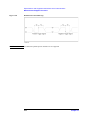
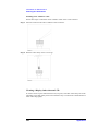
Environmental Requirements
Figure 2-1
Ventilation space at installation site
2. Installation Guide
Ensure free space is available around unit to allow speedy
disconnection of power cable in case of emergency
As described in “Disconnection from Supply Source” on page 39, the disconnecting device
of the 4287A is the plug or the connector of the power cable. When installing the 4287A,
ensure that there is sufficient free space around the unit to allow the plug or the connector
of the power cable (AC outlet side or 4287A side) to be quickly pulled out to disconnect
the power supply in case of emergency.
Chapter 2
21
Installation Guide
How to Install Front Handles/Rack Mounting Flanges
How to Install Front Handles/Rack Mounting Flanges
The Agilent 4287A can be made more convenient for use with two key options: handles
mounted on each side of the front for easy transport and flanges to attach the instrument to
a rack as part of a multi-component measurement system (Table 2-2).
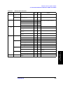
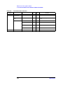
Table 2-2
Agilent 4287A rack mounting options
Name
Agilent Part
Number
Description
Option 1CN handle kit
5063-9229
Two front handles used for transport and relocation of the
Agilent 4287A
Option 1CM rack-mount kit
5063-9216
Two flanges (locking side plates) for mounting the Agilent
4287A on a rack (482.6 mm wide) conforming to EIA Standard
Option 1CN rack-mount kit
and handle kit
5188-4430
Both the rack mounting flanges (locking side plates) and
handles
How to install handle kit (Option 1CN)
Install the handle kit by following these steps:
Step 1. Make sure that all of the contents of the Option 1CN handle kit have been supplied in the
shipping container (Table 2-3).
Table 2-3
Contents of Option 1CN handle kit
Name
Quantity
Front handle
2
Screw
6
Trim strip
2
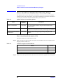
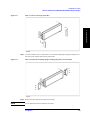
Step 2. Remove the trim strips from both sides of the outer frame of the Agilent 4287A front panel.
22
Chapter 2
Installation Guide
How to Install Front Handles/Rack Mounting Flanges
Figure 2-2
How to remove trim strips from sides
2. Installation Guide
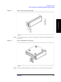
Step 3. Use the included screws to mount the two handles on the sides of the Agilent 4287A front
panel frame.
Figure 2-3
How to install handles on front panel
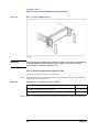
Step 4. Attach the included modified trim strip in order to cover the front panel locking screws.
Chapter 2
23
Installation Guide
How to Install Front Handles/Rack Mounting Flanges
Figure 2-4
How to install modified trim strip
WARNING
If the installed front handle becomes damaged, replace it with a new one immediately.
A damaged handle can break while moving or lifting the instrument and cause
personal injury or damage to the instrument.
How to install rackmount kit (Option 1CM)
Install the rackmount kit by following these steps:
Step 1. Make sure that all of the contents of the rackmount kit (Option 1CM) have been supplied in
the shipping container (Table 2-4).
Table 2-4
Contents of rack-mount kit (Option 1CM)
Name
Quantity
Rackmounting flange (locking side plate)
2
Screw
6
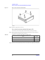
Step 2. Remove the trim strips from both sides of the outer frame of the Agilent 4287A front panel.
24
Chapter 2
Installation Guide
How to Install Front Handles/Rack Mounting Flanges
Figure 2-5
How to remove trim strips from sides
2. Installation Guide
Step 3. Use the included screws to mount the two rack-mounting flanges (locking side plates) on
the sides of the Agilent 4287A front panel frame.
Figure 2-6
How to install rack-mounting flanges (locking side plates) on front panel
Step 4. Remove the four bottom feet and two tilt stands.
NOTE
Do not detach the four feet from the rear panel.
Chapter 2
25
Installation Guide
How to Install Front Handles/Rack Mounting Flanges
Figure 2-7
How to remove bottom feet and tilt stands
Step 5. Mount the Agilent 4287A on the rack.
How to install rack-mount and handle kit (Option 1CP)
Install both the rack-mounting flanges and front handles by following these steps:
Step 1. Make sure that all of the contents of the rack-mount and handle kit (Option 1CM) have
been supplied in the shipping container (Table 2-5).
Table 2-5
Contents of rack-mount and handle kit (Option 1CP)
Name
Quantity
Rack-mounting flange (locking side plate)
2
Front handle
2
Screw
8
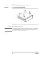
Step 2. Remove the trim strips from both sides of the outer frame of the Agilent 4287A front panel.
26
Chapter 2
Installation Guide
How to Install Front Handles/Rack Mounting Flanges
Figure 2-8
How to remove trim strips from sides
2. Installation Guide
Step 3. Use the included screws to install the front handles and rack-mounting flanges on the sides
of the Agilent 4287A front panel frame.
Figure 2-9
How to install front handles and rack-mounting flanges
Step 4. Remove the four bottom feet and two tilt stands.
NOTE
Do not detach the four feet from the rear panel.
Chapter 2
27
Installation Guide
How to Install Front Handles/Rack Mounting Flanges
Figure 2-10
How to remove bottom feet and tilt stands
Step 5. Mount the Agilent 4287A on the rack.
WARNING
If the installed front handle becomes damaged, replace it with a new one immediately.
A damaged handle can break while moving or lifting the instrument and cause
personal injury or damage to the instrument.
28
Chapter 2
Installation Guide
Connecting Mouse and Keyboard
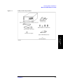
Connecting Mouse and Keyboard
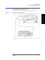
Connect the mouse and keyboard to the designated ports shown in Figure 2-11.
Figure 2-11
Connections of mouse and keyboard
2. Installation Guide
Chapter 2
29
Installation Guide
LAN Connection
LAN Connection
Step 1. Make the appropriate settings on the 4287A for connecting to a Local Area Network
(LAN) according to “Configuring the Network” on page 228.
Step 2. Connect the Agilent 4287A to the LAN according to Figure 2-12.
NOTE
Before connecting to the LAN, be sure to perform the correct LAN settings on the 4287A.
If the appropriate LAN settings are not made, damage to the network could occur when
connecting to the LAN.
Figure 2-12
LAN Connection
30
Chapter 2
Installation Guide
Connecting the Test Head
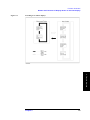
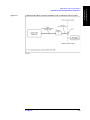
Connecting the Test Head
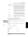
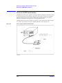
Connecting the DUT when using a special test fixture
When taking measurements while using special test fixtures with 7-mm terminals like the
Agilent 16196A, follow these steps to connect the test head, test fixture stand, and
3.5-mm-to-7-mm adapter.
2. Installation Guide
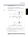
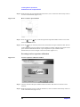
Figure 2-13
Connecting test head to test fixture stand
3.5-mm-to-7-mm
adapter
Test fixture stand
Test head
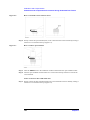
Step 1. As shown in Figure 2-13 (1), attach the test head to the test fixture stand with two screws.
At this point, do not tighten the screws completely (there should be some play).
Step 2. As shown in Figure 2-13 (2), align the 3.5-mm-to-7-mm adapter with the hole in the test
fixture stand and gently insert the adapter.
Step 3. As shown in Figure 2-13 (3), tighten the connector nut of the 3.5-mm connector with the
provided wrench (for 3.5 mm/SMA connector).
Chapter 2
31
Installation Guide
Connecting the Test Head
NOTE
Be sure to use the provided wrench (for 3.5 mm/SMA connector) when tightening the
connector nut of the 3.5-mm connector. Using another wrench could result in damage to
the connector, which would cause incorrect measurements in the future.
Step 4. Firmly tighten the two screws shown in Figure 2-13 (1).
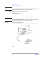
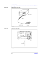
Step 5. Attach the three N(m)-SMA(f) adapters to the RF OUT, PORT 1, and PORT 2 terminals of
the 4287A test head interface.
Connect the three SMA(m) connectors (RF OUT, PORT 1, PORT 2) of the test head cable
to the SMA(f) terminals of the adapters attached in Step 5. Then tighten each of the
connectors using the provided wrench (for 3.5-mm/SMA connector) (Figure 2-14).
NOTE
Be sure to use the provided wrench (for 3.5 mm/SMA connector) when tightening the
connector nut of the 3.5-mm connector. Using another wrench could result in damage to
the connector, which would cause incorrect measurements in the future.
Figure 2-14
Connecting test head cable to 4287A
Agilent 4287A
Test head interface
SMA(f)-N(m) adapter
RF OUT
PORT 1
PORT 2
Test head (with cable)
32
Chapter 2
Installation Guide
Connecting the Test Head
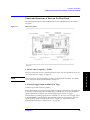
When using with the test head fixed on a handler, etc.
The test head can be attached to a handler or other automatic equipment instead of using a
special test fixture. In this case, secure the test head to the device using the four screw holes
provided in the test head as appropriate. Connect the suitable cable, connectors, test fixture,
etc. for connection of the DUT to the 3.5-mm terminal of the test head.
To minimize additional error in measurement, the distance from the test head’s 3.5-mm
terminal to the DUT connection side should be kept as short as possible.
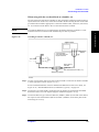
Figure 2-15
Attaching test head to a handle, etc.
2. Installation Guide
NOTE
Agilent 4287A
Connect directly
if the cable does not
require extension
SMA(f)-N(m)
adapter
Test head
When cable is
extended
Test head cable (1 m)
Option 020
Test Head Extension Cable (1 m)
SMA(f)-N(n) adapter
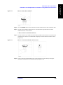
Step 1. Use one or more of the four screw holes in the test head to secure the test head to a handle
or other appropriate location (Figure 2-15 (1)).
For the external dimensions of the test head and the dimensions of the screw holes, see
Figure 12-12, “Test Head Dimensions (in millimeters, typical),” on page 279.
Step 2. Connect the 1-m cable already connected to the test head to the optional 020 Test Head
Extension Cable (1 m) if the original length is insufficient (Figure 2-15 (2)).
Step 3. Connect the three N-type connectors (RF OUT, PORT 1, PORT 2) at the end of the cable to
the respective test head interfaces (RF OUT, PORT 1, PORT 2) on the front panel of the
4287A (Figure 2-15 (3)).
Chapter 2
33
Installation Guide
Connecting the Test Head
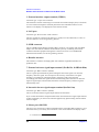
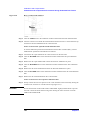
Caution for connecting the SMA connector to the test head connector
Do not rotate the cable to connect the SMA(male) connector to the test head. Rotating the
cable may cause damage to the cable’s center conductor. Be sure to rotate the connector nut
to connect the SMA cable.
Figure 2-16
Caution for connecting the SMA(male) connector
34
Chapter 2
Installation Guide
Preparation for Power Supply
Preparation for Power Supply
Before turning on power to the equipment, be sure to verify the following:
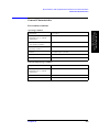
Check the power supply
Check that the power supplied to the Agilent 4287A meets the following requirements:
2. Installation Guide
Requirements
Voltage
90 to 132 VAC or 198 to 264 VAC *1
Frequency
47 to 63 Hz
Maximum power consumption
350 VA
*1. Switched automatically by the Agilent 4287A in conformity to the voltage.
Verification and connection of power cable
The three-wire power cable attached to the Agilent 4287A has one wire serving as a
ground. Use of this power cable allows the Agilent 4287A to be connected to ground,
thereby protecting you against electric shock via the power outlet.
Step 1. Check whether the power cable is damaged or not.
WARNING
NEVER use a power cable showing any sign of damage. Faulty cables can cause
electric shock.
Step 2. Use the supplied cable to connect between the power terminal on the rear panel of the
Agilent 4287A and a three-wire power outlet with the grounding prong firmly connected in
the ground slot.
WARNING
Use the attached three-wire power cable with grounding wire to securely ground the
Agilent 4287A.
Figure 2-17 shows the power cable options.
Chapter 2
35
Installation Guide
Preparation for Power Supply
Figure 2-17
Power cable options
36
Chapter 2
Installation Guide
Preparation for Power Supply
Blown fuse
If the fuse appears to have blown during operation, this equipment may be subject to
failure and must be repaired. Contact the Agilent Technologies sales office or the company
from which you purchased the equipment.
spec :UL/CSA Type, Slo-Blo, 8 A 250 V
WARNING
Do NOT replace the fuse yourself: this may be dangerous.
2. Installation Guide
Chapter 2
37
Installation Guide
Turning the Power ON and OFF
Turning the Power ON and OFF
Perform the following steps to turn the power ON or OFF.
Turning the power ON
Step 1. If the standby switch (
(
) in the lower-left part of the front panel is in the pressed down
) position, press the switch to the popped up position (
Step 2. Press the standby switch to the pressed down position (
).
).
This operation turns ON the power, and the 4287A starts the self-test.
Step 3. Confirm that the self-test indicates normal operation.
Normal operation is confirmed by the self-test if no error message appears.
Turning the power OFF
Step 1. Use either of the following methods to turn OFF the 4287A.
•
Press the standby switch (
pressed down (
•
) in the lower-left part of the front panel (now in the
) position) to the popped up (
) position.
Send the shutdown command from an external controller.
These operations will start the 4287A shutdown process (required software and hardware
processes for turning the power off), and the power will turn OFF after a few seconds.
NOTE
Under normal circumstances, always press the standby switch ( ), or send the shutdown
command from the external controller, to actuate the 4287A shutdown process. Never cut
off the power supply directly by disconnecting the power cable plug from the rear
panel of the unit.
If the power supply is cut off directly by disconnecting the power cable plug or by
disconnecting the power supply to the AC outlet, the shutdown process will not be carried
out, and there is a risk of damage to the software or hardware of the 4287A.
38
Chapter 2
Installation Guide
Disconnection from Supply Source
Disconnection from Supply Source
The disconnecting device (device cutting off the power supply) of the 4287A is the plug of
the power cable (on AC outlet side or 4287A side). When it is necessary to disconnect the
power supply in order to avoid shock hazards, etc., pull out the power cable plug from
either the AC outlet side or the 4287A side.
To allow this operation to be performed smoothly, be sure to follow the guidelines in
“Ensure free space is available around unit to allow speedy disconnection of power cable in
case of emergency” on page 21.
When turning the power OFF under normal circumstances, always follow the methods
described in “Turning the power OFF” on page 38.
Chapter 2
39
2. Installation Guide
NOTE
Installation Guide
Initial Registration of 4287A
Initial Registration of 4287A
When you start up the 4287A for the first time or after executing system recovery, you
need to perform the initial registration of the Windows 2000 operating system of the
4287A.
NOTE
You cannot use the front panel keys during the initial registration of the 4287A therefore
connect the mouse and the keyboard before turning on the power. An USB mouse is not
supported.
NOTE
If you perform the following procedure incorrectly, a message asking you whether to return
to the previous registration screen and perform the registration appears. In this case, follow
the instruction to return to the previous registration screen.
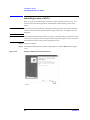
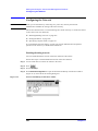
Step 1. Turns on the 4287A.
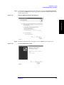
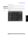
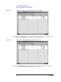
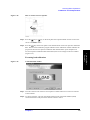
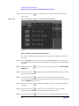
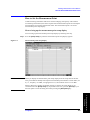
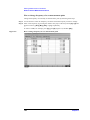
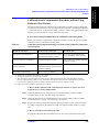
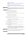
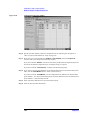
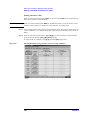
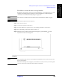
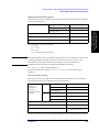
Step 2. The Windows 2000 Professional Setup wizard appears. Click the Next > button (Figure
2-18).
Figure 2-18
Windows 2000 Professional Setup wizard
40
Chapter 2
Installation Guide
Initial Registration of 4287A
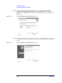
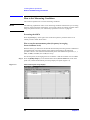
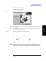
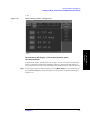
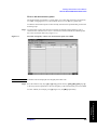
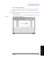
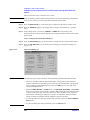
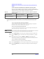
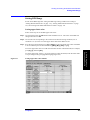
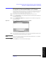
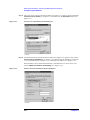
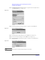
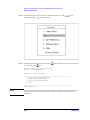
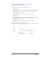
Step 3. In the Windows 2000 Professional Setup dialog box, select the I accept this agreement
box and click the Next >button (Figure 2-19). Then, the Windows 2000 operating system is
restarted automatically.
Figure 2-19
Windows 2000 Professional Setup dialog box
2. Installation Guide
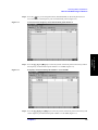
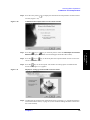
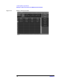
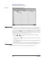
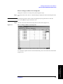
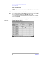
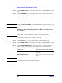
Step 4. The Network Identification wizard appears. Click the Next > button (Figure 2-20).
Figure 2-20
Network Identification wizard
Chapter 2
41
Installation Guide
Initial Registration of 4287A
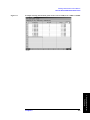
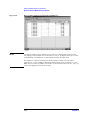
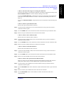
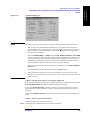
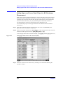
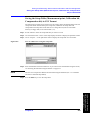
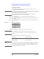
Step 5. In the Network Identification Wizard dialog box (1/2), select the Windows always
assumes the following user has logged on to this computer box and check that
agt_instr is in the User Name box. If not, type in agt_instr. Finally, click the Next> button
(Figure 2-21).
Figure 2-21
Network Identification Wizard dialog box (1/2)
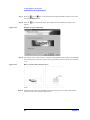
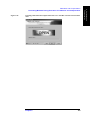
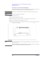
Step 6. In the Network Identification Wizard dialog box (2/2), click the Finish button to finish the
initial registration of the 4287A (Figure 2-22). Then, the measurement display of the4287A
appears.
Figure 2-22
Network Identification Wizard dialog box (2/2)
42
Chapter 2
Installation Guide
Setting the Internal Clock
Setting the Internal Clock
You can set the date/time displayed at the lower right of the screen. When you save data in
the storage unit, for example, the internal clock data will be used. The following describes
the setting procedure that uses keys on the front panel.
NOTE
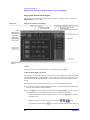
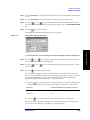
Setting the Date/Time
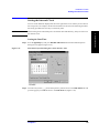
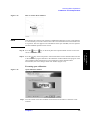
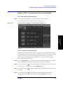
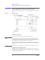
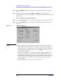
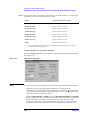
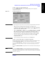
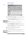
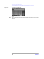
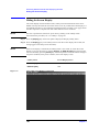
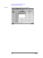
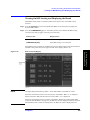
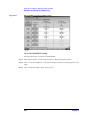
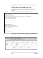
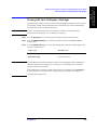
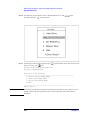
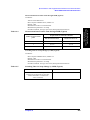
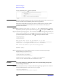
Step 1. Press the [System] key and press Set Date and Time button the Date/Time Properties
dialog box will appear (Figure 2-23).
Figure 2-23
Date/Time Properties Dialog Box (“Date & Time” Tab)
Step 2. Turn the rotary knob (
)on the front panel to point the focus to the Date & Time tab and
press the [→] key to move the focus to the Time Zone tab (Figure 2-24).
Chapter 2
43
2. Installation Guide
When turning on the instrument power for the first time after delivery, always be sure to set
the internal clock.
Installation Guide
Setting the Internal Clock
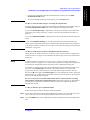
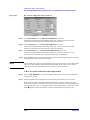
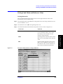
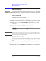
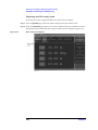
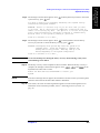
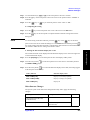
Figure 2-24
Date/Time Properties Dialog Box (“Time Zone” Tab)
Step 3. Turn the rotary knob (
) on the front panel to point the focus to the Time Zone box and
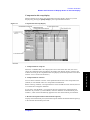
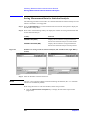
press the [←]/[→] or [↓]/[↑] key to select the time zone.
NOTE
When you select the time zone for summer time, the Automatically adjust clock for
daylight saving changes box becomes selectable. To set the function of automatically
making summertime adjustment to ON, turn the rotary knob (
) to point the focus to the
Automatically adjust clock for daylight saving changes box and press the rotary knob
(
) to display the √ mark (Figure 2-24).
Step 4. Turn the rotary knob (
) on the front panel to point the focus to the Time Zone tab and
press the [←] key to move the focus to the Date & Time tab.
Step 5. By referring to Figure 2-23, turn the rotary knob (
) on the front panel to point the focus
to the desired item. Press the [←]/[→] or [↓]/[↑] key to set each item.
Step 6. Turn the rotary knob (
press [Enter] key.
) on the front panel to point the focus to the OK button and then
Turning the Date/Time Display ON and OFF
The Date/time is displayed within the instrument status bar at the lower right of the display
screen.
Step 1. Press the [System] key in the INSTR STATE block. Press the [↓]or [↑] key to move the
focus to the Misc Setup button and then press the [Enter] or [→] key. Press the [↓] or [↑]
key, move the focus to the Clock Setup button, and press the [Enter] or [→]key. Point the
focus to the Show Clock button and press the [Enter] key to set the date/time display
on/off.
44
Chapter 2
Installation Guide
Selection of Test Fixture
Selection of Test Fixture
When the DUT is attached and detached by manual operation, it is possible to use special
test fixtures. Select the appropriate test fixture by referring to Table 2-6. The options listed
in the table may not cover all conditions and characteristics, so please confirm detailed
specifications by referring to the appropriate accessory catalogs and operation manuals.
Table 2-6
Usable test fixtures
2. Installation Guide
Test Fixture
Frequency Range
Components Size (SMD)
16196A
DC to 3 GHz
1608 mm/0603 inch
16196B
DC to 3 GHz
1005 mm/0402 inch
16196C
DC to 3 GHz
0603 mm/0201 inch
16197A
DC to 3 GHz
*1
16191A
DC to 2 GHz
*1
16192A
DC to 2 GHz
*1
16194A
DC to 2 GHz
*1
*1. indicates the direction of contact of the test fixture's electrode.
NOTE
When a special test fixture is used, it is necessary to first attach the test head to the test
fixture stand (at this point, the test head’s 3.5-mm terminal is converted to a 7-mm terminal
by using the 3.5-mm-to-7-mm adapter). For details on how to attach the test head to the test
fixture stand, see “Connecting the DUT when using a special test fixture” on page 31.
Chapter 2
45
Installation Guide
Instructions for Cleaning
About connection of test fixture and DUT
Before actually connecting a DUT and performing measurement, it is necessary to set the
measurement conditions and perform calibration and compensation. Some calibration and
compensation operations have to be performed before the test fixture is connected to the
test head. Accordingly, before connecting the test fixture and the DUT, be sure to set the
measurement conditions and perform calibration and compensation as outlined in Chapter
5, “Setting Measurement Conditions,” on page 101 and Chapter 6, “Calibration and
Compensation,” on page 115.
Instructions for Cleaning
To prevent electrical shock, disconnect the 4287A's power cable from the power outlet
before cleaning.
To clean the exterior of the 4287A, gently wipe the surfaces with a clean dry cloth or a
clean cloth that has been soaked with water and wrung tightly. Do not attempt to clean the
4287A internally.
46
Chapter 2
Installation Guide
Precautions Required When Connecting the 4287A to Automatic Equipment
(Handler), etc.
Precautions Required When Connecting the 4287A to
Automatic Equipment (Handler), etc.
When using the 4287A along with a handler or other automatic equipment in a system, pay
particular attention to the following points.
To confirm the timing of all of the 4287A’s operations and the automatic equipment (or
controller), use the 4287A’s handler interface synchronizing signals (/INDEX, /EOM,
/READY_FOR_TRIG) and the status report mechanism to detect the condition of each
process and to control the automatic equipment synchronized with these signals. By
performing synchronization, trigger errors can be prevented and the measurement
throughput can be maximized. For details on how to make the timing with the
automatic equipment, see the Programming Manual.
If you obtain DC resistance measurement with variance due to noise, it may be caused
by common mode noise which enters the 4287A via the test head cable and the GPIB
cable. To decrease this noise, insert the part where the cables of the test head are tied
into ferrite cores as many as possible (see Figure 2-25). If you connect a GPIB cable,
wind it around a core as many turns as possible (see Figure 2-26).
Use cores having large impedance at low frequency. The following table shows some
example of the cores which you can get as of December 2001.
For the test head cable
For the GPIB cable
Toshiba FS26x16x10W
μ:
100000 @10 kHz
AL-value:
67.8 μH/N2 @10 kHz
Hitachi Metals F10080G
μ:
70000 @10 kHz
AL-value:
30.0 - 65 μH/N2 @10 kHz
When performing calibration and compensation, it is recommended that you use the
internal raw data for calibration and compensation to determine the success or failure
of the calibration and compensation. For details, see the chapter “Preparations for
Accurate Measurement” in the Programming Manual.
Do not rotate the cable to connect the SMA(male) connector to the test head. Rotating
the cable may cause damage to the cable’s center conductor. Be sure to rotate the
connector nut to connect the SMA cable. For more details, refer to the “Caution for
connecting the SMA connector to the test head connector” on page 34.
Chapter 2
47
2. Installation Guide
When turning OFF the 4287A, be sure use the standby switch on the front panel or the
shutdown command from an external controller. For details, see “Turning the power
OFF” on page 38.
Installation Guide
Precautions Required When Connecting the 4287A to Automatic Equipment
(Handler), etc.
Figure 2-25
Using cores (test head cable)
Figure 2-26
Using a core (GPIB cable)
48
Chapter 2
3. Learning Basic
Operations
3
Learning Basic Operations
This chapter explains the basic operation procedures of the Agilent Technologies 4287A
RF LCR Meter by using measurement examples. This is intended to familiarize you with
the 4287A if you are using this instrument for the first time.
49
Learning Basic Operations
What You Must Keep on Hand
What You Must Keep on Hand
To use the examples of measurement shown in this chapter, prepare the following items:
Table 3-1
What you must keep on hand
Name
Quantity
Agilent 4287A RF LCR meter (with mouse)
1
Test head (with 1-meter cable)*1
1
N(m)-SMA(f) adapter*2
3
Wrench (for 3.5-mm/SMA connector)*2
1
Agilent 16195B 7-mm calibration kit*3
1
Test fixture stand*4
1
3.5-mm-to-7-mm adapter*5
1
Agilent 16196A SMD Test Fixture*6
1
DUT: Chip inductor (connectable to test fixture to be used)
1
*1.
*2.
*3.
*4.
*5.
*6.
50
Included with the 4287A
Included with the standard 4287A
Included with the Option 700
Included with the Option 710
Included with the Option 720
Other test fixtures can be used if compatible with the 7-mm connector of the same type.
Chapter 3
Learning Basic Operations
What You Must Keep on Hand
Figure 3-1
What you must keep on hand
3. Learning Basic
Operations
Chapter 3
51
Learning Basic Operations
Preparation for Measurement
Preparation for Measurement
Connection between test head and fixture stand
Connect the test head (with 1-meter cable) and test fixture stand to the 4287A as shown in
Figure 3-2. For details, see "Connecting the DUT When Using Special Test Fixture" on
page 29.
Figure 3-2
Connection between test head and fixture stand
NOTE
Open/short/load calibration at the 7-mm-terminal on the tip of the test head is described
later in this chapter. Here the test fixtures (Agilent Technologies 16196A, etc.) for
connection of the DUT are not installed on the test head.
52
Chapter 3
Learning Basic Operations
Preparation for Measurement
Turning ON the power
Press the power switch in the lower-left area of the 4287A front panel to turn on the power.
NOTE
Extra caution is required when turning the 4287A power ON or OFF. See “Turning the
Power ON and OFF” on page 35.
When the power switch is pressed, the 4287A starts the self-test. After confirmation of
normal operation, the measurement display (Figure 3-3) will appear based on the power-on
default settings.
Figure 3-3
Screen when power is turned ON (single point measurement display)
3. Learning Basic
Operations
Chapter 3
53
Learning Basic Operations
How to Set Measuring Conditions
How to Set Measuring Conditions
This sections explains how to set the measuring conditions.
NOTE
The following explanation of how to set measuring conditions assumes that you are using
the keys on the front panel of the 4287A. If you want to know the setting procedure when
using a keyboard or mouse, see “4287A Key Operation Overview” on page 99.
Presetting the 4287A
Press the [Preset] key on the right corner of the front panel to preset the 4287A to its
initially set state called “Preset state.”
How to set the measurement point (frequency/averaging
factor/oscillator level)
With the 4287A, you must enter the desired measurement point along with its conditions in
the measurement point setup display before starting measurement. The following
procedure shows a case when four measurement points with different frequencies (i.e., 1
MHz, 10 MHz, 100 MHz, and 1 GHz) are set up.
For all four points, the averaging factor is assumed as 1 and the oscillator level as 0 dBm.
Step 1. Press the [Setup View] key on the measurement block (MEASUREMENT) of the front
panel once, and the measurement point setup display will apear (Figure 3-4).
Figure 3-4
Measurement point setup display
54
Chapter 3
Learning Basic Operations
How to Set Measuring Conditions
Step 2. Press the
key in the navigation block (NAVIGATION) on the front panel twice to
move the cursor to the Frequency cell of measurement point 2 (Figure 3-5).
Figure 3-5
Cursor moved to frequency cell of measurement point number 2
Figure 3-6
Frequency of measurement point number 2 set to 10 MHz
Step 4. Press the [1], [0], [0], and [M/μ] keys on the entry block of the front panel consecutively and
set the frequency of measurement point number 3 to 100 MHz (Figure 3-7).
Chapter 3
55
3. Learning Basic
Operations
Step 3. Press the [1], [0], and [M/μ] keys on the entry block of the front panel consecutively and set
the frequency of measurement point number 2 to 10 MHz (Figure 3-6).
Learning Basic Operations
How to Set Measuring Conditions
Figure 3-7
Frequency of measurement point number 3 set to 100 MHz
Step 5. Press the [1] and [G/n] keys on the entry block of the front panel consecutively and set the
frequency of measurement point number 4 to 1 GHz (Figure 3-8).
Figure 3-8
Frequency of measurement point number 4 set to 1 GHz
Step 6. Press the [Meas View] key on the measurement block of the front panel to go back to the
first single point measurement display (Figure 3-3 on page 53).
56
Chapter 3
Learning Basic Operations
Calibration and Compensation
Calibration and Compensation
After completing measurement point setting, perform calibration and compensation
NOTE
Calibration and compensation are carried out at the same point as the normally set
measurement point; therefore, the measurement point setting should have been completed
before calibration and compensation.
The following description uses the “wizard” function, which ensures easy execution of
calibration and compensation by displaying clear and simple guidance.
Low-loss capacitor calibration, port extension compensation, open compensation, and
short compensation in addition to open/short/load calibration are explained in the
measurement examples below.
The definition of the calibration kit and compensation kit remains the same as that in the
presetting phase.
Setting with the calibration and compensation wizard
NOTE
When using test fixtures other than 16191A, 16192A, 16193A, 16194A, 16196A, 16196B,
or 16196C, register the electrical length as described in “Registering the Electrical Length
of Unregistered Test Fixtures” on page 149 before making settings using the calibration
and compensation wizard.
Step 1. Press the [Cal/Compen] key in the instrument state block (INSTR STATE) on the front
panel to display the Cal/Compen softkey menu in the right side of the screen.
Step 2. Turn the rotary knob (
) in the navigation block (NAVIGATION) on the front panel to
move the cursor in the softkey menu to the SETUP CAL WIZARD key.
Step 3. Press the rotary knob (
) to display the Calibration Wizard Setting dialog box (Figure
3-9).
Figure 3-9
Calibration Wizard Setting dialog box
Chapter 3
57
3. Learning Basic
Operations
Perform the following steps before using the calibration and compensation wizard to make
settings.
Learning Basic Operations
Calibration and Compensation
NOTE
When using the 4287A for measurement, open compensation, short compensation and load
compensation must be performed under any circumstance. The calibration and
compensation wizard setting feature has been designed so that, in addition to these three
essential settings, your desired calibration and compensation settings may be selected.
Step 4. Confirm that a check mark √ appears in the Low-Loss C check box in the Calibration area.
Step 5. Confirm that a check mark (√) only appears in the Open and Short check boxes in the
Compensation area.
Step 6. Confirm that Active table only is selected () so that calibration and compensation is only
performed for the measurement point in the selected measurement point table.
Step 7. Press the
key or
key on the front panel the required number of times to move the
cursor to the Fixture box.
Step 8. Press the
key or
key on the front panel the required number of times to select
the model number of the test fixture to be used.
NOTE
When using test fixtures other than 16191A, 16192A, 16193A, 16194A, 16196A, 16196B,
or 16196C, the electrical length must be registered as described in “Registering the
Electrical Length of Unregistered Test Fixtures” on page 149 before making settings with
the calibration and compensation wizard. When the name of the test fixture and its
electrical length are registered, the test fixture becomes selectable in Step 8 of this
procedure.
Step 9. Press the
key or
key on the front panel the required number of times to move the
cursor to the OK button.
Step 10. Press the
key on the front panel the required number of times to complete the setting
of the calibration and compensation wizard and close the dialog box.
NOTE
To cancel the setting of the calibration and compensation wizard, press the
key or the
key on the front panel to move the cursor in the dialog box to the Cancel button and
then press the
key. If the setting is cancelled, the settings shown when the dialog box
was first opened will remain unchanged and be used as they are.
Executing short calibration
Use the following procedure to perform short calibration of the 7-mm terminal on the tip of
the test head.
Step 1. Turn the rotary knob (
) to move the cursor in the softkey menu to the CAL WIZARD
key.
58
Chapter 3
Learning Basic Operations
Calibration and Compensation
Step 2. Press the rotary knob (
) to display the calibration and compensation wizard welcome
window (Figure 3-10).
Figure 3-10
Calibration and compensation wizard welcome window
key or
key on the front panel to select the Cal/Compen for a Fixture
Measurement option () (filled circle should appear inside the radio button).
Step 4. Press the
key or
key on the front panel the required number of times to move the
cursor to the Next> button.
Step 5. Press the
key on the front panel. The window for setting up the test head and test
fixture stand (Figure 3-11) appears.
Figure 3-11
Display for setting up test head and test fixture stand
Step 6. Confirm that the setup has been performed as shown in Figure 3-2, “Connection between
test head and fixture stand,” on page 52 (in this condition nothing should be connected to
the 7-mm terminal).
Chapter 3
59
3. Learning Basic
Operations
Step 3. Press the
Learning Basic Operations
Calibration and Compensation
Step 7. Press the
key or
key on the front panel the required number of times to move the
cursor to the Next> button.
Step 8. Press the
appears.
Figure 3-12
key on the front panel. The window for short calibration (Figure 3-12)
Window for short calibration
Step 9. The outside of the 7-mm connector of the test head installed on the test fixture stand should
be turned clockwise until the connector sleeve protrudes to its full extent at the top (Figure
3-13).
Figure 3-13
How to extend 7-mm connector sleeve
Step 10. While pressing on the short standard (0 Ω) from the top, turn it clockwise and securely
connect it to the 7-mm terminal (Figure 3-14).
60
Chapter 3
Learning Basic Operations
Calibration and Compensation
Figure 3-14
How to connect short standard
NOTE
After turning the connector nut of the short standard and attaching it to the 7-mm terminal,
it is not necessary to turn the connector nut of the 7-mm terminal on the test head side to fix
it in position. This also applies to the installations of the open standard, low-loss capacitor
and load standard explained in this section.
Step 11. Press the
key or
key on the front panel the required number of times to move the
Step 12. Press the
key on the front panel to start measurement of short calibration data. The bar
in the Calibration progress indicator in the calibration window indicates the progress of the
short calibration data measurement. Upon completion of short calibration data
measurement, the screen changes to the next window (Figure 3-15).
Executing open calibration
Figure 3-15
Open calibration window
Step 1. Turn the outside of the short standard counterclockwise and remove it from the 7-mm
terminal.
Chapter 3
61
3. Learning Basic
Operations
cursor to the Next> button.
Learning Basic Operations
Calibration and Compensation
Step 2. While pressing the open standard (0S) from above, turn it clockwise and securely connect
it to the 7-mm terminal (Figure 3-16).
Figure 3-16
How to connect open standard
Step 3. Press the
key or
key on the front panel the required number of times to move the
cursor to the Next> button.
Step 4. Press the
key on the front panel to start measurement of open calibration data. The bar
in the Calibration progress indicator in the calibration window indicates the progress of the
open calibration data measurement. Upon completion of open calibration data
measurement, the screen changes to the next window (Figure 3-17).
Executing low-loss capacitor calibration
Figure 3-17
Low-loss capacitor calibration window
Step 1. Turn the outside of the open standard counterclockwise and remove it from the 7-mm
terminal.
Step 2. While pressing the low-loss capacitor from above, turn it clockwise and securely connect it
to the 7-mm terminal (Figure 3-18).
62
Chapter 3
Learning Basic Operations
Calibration and Compensation
Figure 3-18
How to connect low-loss capacitor
Step 3. Press the
key or
key on the front panel the required number of times to move the
cursor to the Next> button.
Executing load calibration
Figure 3-19
Load calibration window
Step 1. Turn the connector nut of the low-loss capacitor counterclockwise to remove it from the
7-mm terminal.
Step 2. As shown in Figure 3-20, turn the outside connector nut of the load standard (50 Ω)
counterclockwise to fully retract the internal connector sleeve.
Chapter 3
63
3. Learning Basic
Operations
Step 4. Press the
key on the front panel to start measurement of low-loss capacitor calibration
data. The bar in the Calibration progress indicator in the calibration window indicates the
progress of the low-loss capacitor calibration data measurement. Upon completion of
low-loss capacitor calibration data measurement, the screen changes to the next window
(Figure 3-19).
Learning Basic Operations
Calibration and Compensation
Figure 3-20
How to retract connector sleeve of load standard
Step 3. While pressing the load standard (50 Ω) from above, turn the connector nut clockwise and
securely connect it to the 7-mm terminal (Figure 3-21).
Figure 3-21
How to connect load standard
Step 4. Press the
key or
key on the front panel the required number of times to move the
cursor to the Next> button.
Step 5. Press the
key on the front panel to start measurement of load calibration data. The bar
in the Calibration progress indicator in the calibration window indicates the progress of the
load calibration data measurement. Upon completion of load calibration data measurement,
the screen changes to the next window (Figure 3-22).
64
Chapter 3
Learning Basic Operations
Calibration and Compensation
Connection of Test Fixture
Connect the test fixture as follows:
Figure 3-22
Test fixture connection window
Step 2. Turn the connector nut of the 7-mm connector counterclockwise to retract the connector
sleeve completely inside (Figure 3-23).
Figure 3-23
Retracting the 7-mm connector connector sleeve
Step 3. Fit the tips of the two mounting posts on the test fixture stand to the two holes of the test
fixture and fit the 7-mm connector on the test fixture stand to the 7-mm connector on the
test fixture. Turn the connector nut of the 7-mm connector on the test fixture stand
counterclockwise, as viewed from above, and firmly lock it to the test fixture’s 7-mm
connector.
Chapter 3
65
3. Learning Basic
Operations
Step 1. Turn the connector nut of the low-loss capacitor counterclockwise and remove it from the
7-mm terminal.
Learning Basic Operations
Calibration and Compensation
Figure 3-24
How to install test fixture on test fixture stand
Step 4. Press the
key or
key on the front panel the required number of times to move the
cursor to the Next> button.
Step 5. Press the
key on the front panel to move to next window (Figure 3-25).
Executing short compensation
Figure 3-25
Window for short compensation
66
Chapter 3
Learning Basic Operations
Calibration and Compensation
Step 1. Set the DUT connection terminal of the test fixture to the state in which short
compensation is performed. For information on the procedure to set the short state, see the
Operation Manual for the test fixture to be used.
Step 2. Press the
key or
key on the front panel the required number of times to move the
cursor to the Next> button.
Step 3. Press the
key on the front panel to start measurement of short compensation data. The
bar in the Compensation progress indicator in the compensation window indicates the
progress of the short compensation data measurement. Upon completion of short
compensation data measurement, the screen changes to the next window (Figure 3-26).
Executing open compensation
Figure 3-26
Window for open compensation
3. Learning Basic
Operations
Step 1. Set the DUT connection terminal of the test fixture to the state in which open compensation
is performed. For information on the procedure to set the open state, see the Operation
Manual for the test fixture to be used.
Step 2. Press the
key or
key on the front panel the required number of times to move the
cursor to the Next> button.
Step 3. Press the
key on the front panel to start measurement of open compensation data. The
bar in the Compensation progress indicator in the compensation window indicates the
progress of the open compensation data measurement. Upon completion of open
compensation data measurement, the screen changes to the next window (Figure 3-27).
Chapter 3
67
Learning Basic Operations
Calibration and Compensation
Figure 3-27
Window for closing calibration and compensation wizard
Step 4. Press the
key or
key on the front panel the required number of times to move the
cursor to the Finish button.
Step 5. Press the
NOTE
key on the front panel to close the calibration and compensation wizard.
Upon completion of calibration and compensation, Cor, Cmp and Del are lit in blue in the
equipment status area at the bottom of the display.
68
Chapter 3
Learning Basic Operations
Display of DUT Connection and Measurement Result
Display of DUT Connection and Measurement Result
DUT connection and measurement
Step 1. Connect the DUT according to the Operation Manual for the test fixture.
The measurement result is displayed as shown in Figure 3-28.
Figure 3-28
Measurement result display (measurement point number = 1)
3. Learning Basic
Operations
How to change measurement point
In Figure 3-28, the measurement result is only displayed for the 1-MHz point among the
four measurement points (1 MHz, 10 MHz, 100 MHz and 1 GHz) set according to “How to
set the measurement point (frequency/averaging factor/oscillator level)” on page 54.
Follow these steps to change the measurement point on which you want to perform
measurements and display results.
Step 1. Press the [Stml Select] key on the measurement block (MEASUREMENT) of the front
panel. The Stml Select softkey menu appears on the right side of the display.
Step 2. Turn the rotary knob (
) in the navigation block (NAVIGATION) on the front panel to
move the cursor in the softkey menu to the POINT No.[ ] key.
Step 3. Press the rotary knob (
) to display the POINT No.[ ] softkey menu on the right side of
the display.
Step 4. Turn the rotary knob (
) to move the cursor in the softkey menu to the softkey
corresponding to the desired measurement point number (POINT 4 in this case).
Chapter 3
69
Learning Basic Operations
Display of DUT Connection and Measurement Result
Step 5. Press the rotary knob (
) to accept the selection of the measurement point number
(Figure 3-29).
Figure 3-29
Measurement point changed to measurement point number 4
How to change measurement parameters
Set which of the four measurement parameters is to appear on the display by following
these steps.
Step 1. Press the [Prmtr] key on the measurement block (MEASUREMENT) of the front panel.
The measurement parameter selection menu appears in the softkey area on the right side of
the display.
Step 2. Turn the rotary knob (
) to move the cursor in the softkey menu to the SETUP MEAS
PRMTRS key.
Step 3. Press the rotary knob (
) to display the SETUP MEAS PRMTRS softkey menu on the
right side of the display.
Step 4. Turn the rotary knob (
) to move the cursor in the softkey menu to the softkey
corresponding to the measurement point number whose measurement parameters should be
changed (PRMTR-1 [ ] in this case).
Step 5. Press the rotary knob (
) to display the PRMTR-1 [ ] softkey menu on the right side of
the display.
Step 6. Turn the rotary knob (
) to move the cursor in the softkey menu to the softkey
corresponding to the desired measurement parameter (Ls in this case).
Step 7. Press the rotary knob (
70
) to accept the selection of the measurement parameter (Figure
Chapter 3
Learning Basic Operations
Display of DUT Connection and Measurement Result
3-30).
Figure 3-30
Measurement parameter 1 changed to Ls
In Figure 3-28 on page 69 and Figure 3-29 on page 70, only one of the set measurement
points is selected for measurement and display. However, measurement and display can
also be executed at all of the set measurement points simultaneously by following this step.
Step 1. On the single point measurement display, press the [Meas View] key on the measurement
block (MEASUREMENT) of the front panel once to select the list measurement display
(Figure 3-31).
Chapter 3
71
3. Learning Basic
Operations
Measurement and display of all set measurement points
(list measurement)
Learning Basic Operations
Display of DUT Connection and Measurement Result
Figure 3-31
Display of list measurement
72
Chapter 3
4. Function Overview
4
Function Overview
This chapter describes the functions of the Agilent Technologies 4287A that can be
accessed from the front panel, rear panel, and LCD display.
73
Function Overview
Names and Functions of Parts on the Front Panel
Names and Functions of Parts on the Front Panel
This section describes the names and functions of the individual parts on the 4287A’s front
panel.
Figure 4-1
4287A front panel
1. Stand-by switch (
)
This is the switch used to turn the power to the 4287A ON and OFF.
NOTE
To turn off the power to the 4287A, be sure to press this switch or send the shutdown
command from an external controller to activate the 4287A’s shutdown processing of
software and hardware used to turn off power. Never directly turn off the power supply by
removing the power cable from the rear panel’s power receptacle.
If the power supply to the power cable receptacle is turned off directly, the shutdown
process does not activate and the 4287A software and hardware may be damaged, leading
to failure.
For turning the power ON and OFF, see “Turning the Power ON and OFF” on page 38.
2. Built-in 3.5-inch floppy disk drive
This floppy disk drive is used to save the 4287A setup state and measurement data on a
floppy disk and to call them up when necessary. It is compatible with a 3.5-inch 720 KB or
1.44 MB DOS formatted floppy disk.
74
Chapter 4
Function Overview
Names and Functions of Parts on the Front Panel
3. Color LCD display
Almost all of the information required for the measurement value, setup state, result of data
processing, result of evaluation, menu bar, softkey labels and indications is shown on the
color LCD display. This display features an 8.4-inch TFT color screen.
For more on the information appearing on the LCD display, see “Names and Functions of
Display Areas on the LCD Display” on page 82.
4. Navigation block (NAVIGATION)
This block contains a group of keys and a knob used to move the cursor position shown on
the display and execute the instruction determined by the cursor position. Specifically, the
block comprises a rotary knob, arrow keys and an Enter key (gently pressing the rotary
knob also performs the Enter function).
Turning the knob clockwise or counterclockwise moves the
condition setup cursor (shown as highlighted softkey label
or setup table cell outlined by a bold border) vertically.
Pressing this knob executes the function indicated by the
cursor.
(Rotary knob)
keys
Pressing these keys moves the condition setup cursor
vertically or horizontally.
(Arrow keys)
key
Pressing this key executes the function indicated by the
cursor. It has the same function as pressing the rotary knob.
5. Measurement block (MEASUREMENT)
This block contains a group of hardkeys for setting up basic measurement conditions.
Pressing this key brings up the setup display. The following
five setup displays are available: measurement point setup
display, calibration kit setup display, compensation kit
setup display, bin sort setup display, and other setup
display. These five displays can be switched in sequence by
repeatedly pressing this key when the setup display is
indicated.
[Meas View] key
Pressing this key brings up the measurement display. There
are two types of measurement displays: single point
measurement display and list measurement display. These
two displays can be toggled by pressing this key when the
measurement display is indicated.
[Stml Select] key
Displays the Stml Select softkey menu in the softkey area
on the right side of the display. These softkeys are used to
select the actual measurement point from among the
measurement points preset on the softkey measurement
point setup display.
Chapter 4
75
4. Function Overview
[Setup View] key
Function Overview
Names and Functions of Parts on the Front Panel
[Prmtr] key
Displays the Prmtrs softkey menu in the softkey area on the
right side of the display. These softkeys are used to select
the measurement parameter.
6. Instrument state block (INSTR STATE)
This block contains a group of hardkeys used to set up the functions to control and manage
the comparator, measurement result display, trigger, saving, calling up, and others.
[Cal/Compen] key
Displays the Cal/Compen softkey menu in the softkey area
on the right side of the display. This menu is used to
execute calibration and compensation.
[Display] key
Displays the Display softkey menu in the softkey area on
the right side of the display. This menu is used to specify
how to display the measurement results.
[Capture] key
This key uses the same hardkey as the [Display] key. When
the key is pressed, an image of the screen at that point in
time is copied to the clipboard (temporary memory). This
temporarily saved image data can later be named with a
filename and saved on a storage device (floppy disk or
nonvolatile memory).
[Trigger Mode] key
Displays the Trigger Mode softkey menu in the softkey
area on the right side of the display. This menu is used to
set the measurement start instruction method (trigger
mode).
[Save/Recall] key
Displays the Save/Recall softkey menu in the softkey area
on the right side of the display. This menu is used to save
the 4287A setup state and measurement data in a storage
device of the 4287A (floppy disk or nonvolatile memory)
and to call them up when needed.
[Trigger] key
This is a manual trigger key. The trigger is activated by
pressing this key in the manual trigger mode.
[System] key
Displays the System softkey menu in the softkey area on
the right side of the display. This menu is used to control
and manage the entire measuring instrument.
7. Entry block (ENTRY)
This block contains a group of hardkeys for entering numerical values and strings of
characters. You can operate these keys after moving the cursor to the position where you
want to enter numerical values and strings of characters with the keys or the mouse.
[0] through [9][.][-] keys
(numeric entry keys)
76
These keys are used to enter numerical values at the cursor
position. You can confirm the setup based on the entered
numerical value by subsequently pressing a unit key.
Chapter 4
Function Overview
Names and Functions of Parts on the Front Panel
[G/n][M/μ][k/m] and [×1]
keys (unit keys)
Pressing one of these keys after the numerical value is
entered by a numeric entry key confirms your entry of the
input numerical value assigned to the unit. In other words,
these keys execute the setup. Only two prefixes are labeled
on the surface of each key, and the selection of the prefix
and the type of the unit are automatically determined in
conformity with the parameter to be set. The [×1] key
allows the setup to be executed without any prefix.
[Alt] key
Pressing this key allows you to use the menu bar at the top
of the display screen without using the mouse. Then use the
numeric entry keys to enter the menu number you want to
select or operate the navigation block keys to your desired
menu/submenu.
[Cancel] key
This key uses the same hardkey as the [Alt] key. When a
dialog box is displayed and this key is pressed, settings
made using this dialog box are cancelled (the key performs
the same function as the Cancel key in the dialog box).
[Back Space] key
Use this key to erase one character of the entered character
string immediately to the left of the cursor position.
[Preset] key
Use this key to set the 4287A to an initialized state called
“Preset state.”
8. Test Head Interface (TEST HEAD INTERFACE)
This interface includes the three ports used to connect the test head: RF OUT, PORT 1, and
PORT 2. All ports are N-type connectors (female).
NOTE
Do not apply DC voltage or DC current to the test head interface as this could result in
damage.
4. Function Overview
Test Head
The DUT port (see Figure 4-2) corresponds to the IEC61010-1 installation category I.
Figure 4-2
Test Head
Chapter 4
77
Function Overview
Names and Functions of Parts on the Front Panel
NOTE
To prevent the 4287A from malfunctioning, do not apply DC voltage or DC current to the
test head’s DUT port. The capacitor in particular could be charged. When you connect a
capacitor, discharge it sufficiently before connecting it to the test fixture that is connected
to the test head’s DUT port.
78
Chapter 4
Function Overview
Names and Functions of Parts on the Rear Panel
Names and Functions of Parts on the Rear Panel
The following describes the names and functions of the individual parts on the 4287A’s
rear panel.
Figure 4-3
4287A rear panel
1. Power cable receptacle (- LINE)
NOTE
Only use the three-wire grounded power cable provided with the instrument. For details,
see “4. Navigation block (NAVIGATION)” on page 75.
2. External trigger input terminal (Ext Trig)
Connector type: BNC connector (female)
This terminal allows you to input a trigger signal to execute a measurement command. The
rising edge (or falling edge) from the LOW state (or HIGH state) in the TTL compatible
signal is detected as a trigger by this external trigger input terminal. To trigger
measurements by inputting signals into this terminal, it is necessary to set a trigger source
in the EXTERNAL (external trigger input terminal) in advance. For details on the input
signal conditions of this terminal, please refer to Chapter 12, “Specifications and
Supplemental Performance Characteristics,” on page 251.
Chapter 4
79
4. Function Overview
This is the receptacle used for connecting the power cable. For the requirements of its use,
see “Check the power supply” on page 35.
Function Overview
Names and Functions of Parts on the Rear Panel
3. External monitor output terminal (VIDEO)
Connector type: 15-pin VGA connector
This terminal is used for connecting to an external color monitor (display unit). Connection
of a color monitor through this terminal permits the same information shown on the
4287A’s LCD display to be displayed on the external monitor.
4. LAN port
Connector type: RJ-45J UTP*1 LAN connector
This port is used for connecting the 4287A to a LAN (Local Area Network). For how to
use LAN features, see the Programming Manual.
5. GPIB connector
This is a GPIB (General Purpose Interface Bus) connector. Use together with the GPIB
adapter. You can build an automatic measurement system by connecting the external
controller and other equipment through this connector. For how to use GPIB-based
automatic measurement, see the Programming Manual.
6. Handler interface
This interface is used for exchanging data with automatic equipment (handler) in a
production line.
7. External reference signal input terminal (Ext Ref In, 10 MHz 0 dBm)
Connector type: BNC connector (female)
This is a signal input terminal for phase-locking the 4287A test signal to an external
frequency reference signal. You can improve the accuracy of the 4287A test signal
frequency by inputting an external frequency reference signal to this terminal.
Accordingly, the 4287A test signal becomes automatically phase-locked to its reference
signal. If signal input is discontinued, the 4287A internal frequency reference signal is
automatically used.
8. Internal reference signal output terminal (Int Ref Out)
Connector type: BNC connector (female)
This is an internal reference signal output terminal for the 4287A.
If you connect between this output terminal and an external reference signal input terminal
of other equipment, you can use the external equipment by phase-locking with the 4287A
reference signal.
9. Mouse port (MOUSE)
This port is for connection of a PS/2 compatible mouse with a Mini-DIN connector. Use of
the mouse allows you to freely move the arrow cursor on the 4287A LCD display and to
*1. Unshielded Twisted Pair
80
Chapter 4
Function Overview
Names and Functions of Parts on the Rear Panel
effectively perform a great variety of setups.
NOTE
An USB mouse is not supported. Use of a mouse other than the specified one may lead to
operation error. Be sure to only use the mouse provided by Agilent Technologies.
When using a mouse connected to the 4287A, only click the left mouse button.
Consequently, expressions such as “click xxx using the mouse” used in this Manual mean
that you have to press the left mouse button.
10. Mini-DIN keyboard port (KYBD)
This port is for connection of a Mini-DIN type keyboard. Use of the keyboard ensures
effective entry of numerical values and character strings.
NOTE
Use of a keyboard other than the specified one may lead to operation error. Be sure to only
use the keyboard provided by Agilent Technologies.
11. Serial number plate
This seal indicates the product serial number (manufacturing number).
12. Option plate
This seal indicates the options installed on the product.
13. Reserved ports (Reserved)
These ports are not available for use.
4. Function Overview
Chapter 4
81
Function Overview
Names and Functions of Display Areas on the LCD Display
Names and Functions of Display Areas on the LCD Display
The 4287A LCD display screens include the six types of displays (two measurement
displays and four setup displays) explained in Table 4-1.
Table 4-1
Types of 4287A displays
Display type
Measurement
display
Setup display
Function
Single-point measurement
display
Measurement is done at the specified single measurement point
and the result is shown on this display.
List measurement display
All measurements are preset in the specified table according to
the sequence of the measurement point numbers and are listed
on the display.
Measurement point setup
display
A display for setting up measurement points. The required
measurement points are set sequentially, starting from
measurement point number 1, by inputting measurement
conditions (measurement frequency, averaging factor and test
signal level). A maximum of 32 measurement points can be set
in each of the eight tables.
Calibration kit setup
display
A display for setting up the calibration kit definition (value) for
the measurement point set up on the measurement point setup
display.
Compensation kit setup
display
A display for setting up the compensation kit definition (value)
for the measurement point set up on the measurement point
setup display.
Bin sorting setup display
A display for setting up the conditions for bin sorting (sorting by
measurement result).
82
Chapter 4
Function Overview
Names and Functions of Display Areas on the LCD Display
Figure 4-4
Switching of six 4287A displays
4. Function Overview
Chapter 4
83
Function Overview
Names and Functions of Display Areas on the LCD Display
Single point measurement display
The single point measurement display shown in Figure 4-5 appears when you press the
[Meas View] key once or twice.
Figure 4-5
Single point measurement display
1. Title
The user can enter his or her desired title to be displayed in this position.
2. Measurement display menu bar
This menu bar can be used to perform and execute the same operations as those performed
with the [Stml Select] key and [Prmtr] key on the front panel of the 4287A, the keys in the
instrument state block (INSTR STATE), and the softkeys shown in the right side of the
screen.
This menu bar can be operated according to any one of the following methods:
Click the menu name using the mouse connected to the 4287A and select the desired
function from the menu using the mouse.
Press the [Alt] key of the entry block (ENTRY) on the front panel to activate the menu
bar and perform any of the following operations (or combined operations):
•
Enter the menu name number using the numeric entry keys ([0] to [9]) to select the
desired function.
•
Move the cursor on the menu using the arrow keys
navigation block and press the
84
of the
key to select the desired function. Alternatively,
Chapter 4
Function Overview
Names and Functions of Display Areas on the LCD Display
you can turn the rotary knob
press the rotary knob.
instead of pressing the
keys and then
Activate the menu bar by pressing the [Alt] key of the keyboard connected to the
4287A and perform any of the following operations (or combined operations):
NOTE
•
Enter the menu name number using the numeric entry keys ([0] to [9]) of the
keyboard to select the desired function.
•
Move the cursor on the menu using the arrow keys ([↑], [↓], [←] and [→]) of the
keyboard and then press the [Enter] key to select the desired function.
You can release the state by again pressing the menu bar that was activated by pressing the
[Alt] key on the front panel or keyboard.
For the measurement display menu bar, despite whether one point measurement display or
list measurement display is shown, the function (menu contents) does not change
(common).
3. Table number
Displays the currently selected table number. The 4287A has eight tables that each allow a
maximum of 32 measurement points to be set. Use the “Measurement point setup display”
on page 91 to set the measurement point conditions (measurement frequency, averaging
factor, oscillator level for the measurement point number) for each table.
NOTE
To directly call up the table number selection softkey menu, use the mouse to click in the
table number area.
4. Measurement point number
Displays the currently selected measurement point number. Use the “Measurement point
setup display” on page 91 to set the measurement point conditions (measurement
frequency, averaging factor, oscillator level for the measurement point number) for each
table.
To directly call up the measurement point number selection softkey menu, use the mouse to
click in the measurement point number area.
5. BIN sort result
When the BIN sort function is turned ON, the sorting result (BIN number) based on the
measurement results is displayed at this position. For the BIN sort function, see Chapter 8,
“Sorting According to Measurement Results,” on page 171.
6. Measurement frequency
Indicates the measurement frequency of the currently selected measurement point. The
conditions (measurement frequency of measurement point, averaging factor, oscillator
level for the measurement point number) for the measurement points of each table are set
in “Measurement point setup display” on page 91.
Chapter 4
85
4. Function Overview
NOTE
Function Overview
Names and Functions of Display Areas on the LCD Display
NOTE
To directly call up the FREQUENCY softkey menu, click in the measurement frequency
area with the mouse. You can use this softkey menu to select the measurement point by the
measurement frequency instead of the measurement point number.
7. Oscillator level (power)
Displays the oscillator level of the currently selected measurement point. Use the
“Measurement point setup display” on page 91 to set the measurement point conditions
(measurement frequency, averaging factor, oscillator level for the measurement point
number) for each table.
NOTE
To directly call up the POWER softkey menu, click in the oscillator level area with the
mouse. You can use this softkey menu to select the measurement point by the oscillator
level instead of the measurement point number.
8. Averaging factor
Displays the measurement averaging factor of the currently selected measurement point.
Use the “Measurement point setup display” on page 91 to set the measurement point
conditions (measurement frequency, averaging factor, oscillator level for the measurement
point number) for each table.
NOTE
To directly call up the AVERAGE softkey menu, click in the averaging factor area with the
mouse. You can use this softkey menu to select the measurement point by the averaging
factor instead of the measurement point number.
9. Test signal current level monitor value
Displays the monitor value for the current level applied to the DUT in the present
measurement.
10. Test signal voltage level monitor value
Displays the monitor value for the voltage level applied to the DUT in the present
measurement.
11. DC resistance (Rdc) measurement value
When the DC resistance (Rdc) measurement function is ON, this measurement result is
indicated here.
A limit for making “pass or fail” judgment can be set for the DC resistance (Rdc)
measurement result, and this can be used for checking the contact condition of the
measurement electrodes and the DUT in the case of impedance measurement.
NOTE
Because the 4287A's DC resistance (Rdc) measurement function utilizes a two-terminal
method, it is unsuitable for low resistance measurement.
12. Softkey menu name
Displays the generic softkey menu name for a set of the softkeys described in “13.
Softkeys” area.
86
Chapter 4
Function Overview
Names and Functions of Display Areas on the LCD Display
13. Softkeys
The softkeys are shown here. To operate the softkeys, first press the [Stml Select] key or
the [Prmtr] key described in “5. Measurement block (MEASUREMENT)” on page 75, or
the keys described in “6. Instrument state block (INSTR STATE)” on page 76 to call up the
desired softkey menu. Then select the desired softkey using any of the following methods:
Turn the rotary knob
on the front panel clockwise or counterclockwise to
vertically move the selection cursor over the softkey label. Then press the rotary knob
to select the softkey.
Press the
keys on the front panel to vertically move the selection cursor
over the softkey label. Then press
to select the softkey.
Click the softkey label with the mouse connected to the 4287A.
Press the arrow keys ([↑] and [↓]) of the keyboard connected to the 4287A to vertically
move the selection cursor over the softkey label. Then press the [ENTER] key to select
the softkey.
14. Date/time
Displays the current date and time. For details on how to set the date and time (including
turning the indication on or off), see “Initial Registration of 4287A” on page 40.
15. Equipment status
Displays the status of crucial operating conditions of the 4287A.
Definition
UnCal (red display)
Calibration not executed.
Cor (blue display)
Calibration executed.
Cmp (blue display)
Compensation executed.
Del (blue display)
Fixture compensation (electrical length and delay time
compensation) has been set (a value other than 0 has been
set for the electrical length of the fixture).
Int (blue display)
The trigger mode is internal trigger mode (free run). The
4287A itself executes the trigger continuously.
Man (blue display)
The trigger mode is manual trigger mode. Trigger is
executed when the [Trigger] key on the front panel is
pressed.
Ext (blue display)
The trigger mode is external trigger mode. Trigger is
executed by a signal sent through the external trigger input
terminal or the handle interface.
Bus (blue display)
The trigger mode is bus trigger mode. Trigger is executed
via GPIB or LAN.
Chapter 4
87
4. Function Overview
Display
Function Overview
Names and Functions of Display Areas on the LCD Display
Display
Definition
ExtRef (blue display)
The external frequency reference signal is input as
described in “7. External reference signal input terminal
(Ext Ref In, 10 MHz 0 dBm)” on page 80, and the 4287A
test signal is phase-locked to that reference signal.
Comptr (blue display)
Comparator (BIN sort) turned on.
Svc (blue display)
The 4287A is in service mode. The service mode is used
for self-diagnosis and repair of the 4287A. This means that
you cannot obtain a measurement guaranteed by the
specifications. If this indicator is lit during normal use, the
instrument may be malfunctioning.
Ovld (red display)
An overload has occurred in the measurement circuit, and
the measurement value is not correct. This indicator lights
up when the DUT is attached to or detached from the
measurement terminals during measurement.
16. Measurement parameter/measurement value
Displays the measurement parameter/measurement value. The 4287A displays a maximum
of four measurement values for measurement parameters at one time.
NOTE
The four measurement parameters shown on the single point measurement display are
called “measurement parameter 1,” “measurement parameter 2,” “measurement parameter
3,” and “measurement parameter 4” in that order from the top of the display area.
You can directly call up the measurement parameter selection softkey menu by clicking in
the measurement parameter area with the mouse. The measurement parameter need not be
preset on the measurement point setup display; you can change it freely on the
measurement display.
88
Chapter 4
Function Overview
Names and Functions of Display Areas on the LCD Display
List measurement display
The point measurement display shown in Figure 4-6 appears when you press the [Meas
View] key once or twice.
Figure 4-6
List measurement display
1. Measurement point number
2 to 5. Labels 1 to 4
You can select one parameter for each of the four labels from among the following and
display the parameter’s value in the corresponding column.
•
Measurement parameter 1 (the top measurement parameter shown in the “Single point
measurement display” on page 84),
•
Measurement parameter 2 (the second measurement parameter shown in the “Single
point measurement display” on page 84),
•
Measurement parameter 3 (the third measurement parameter shown in the “Single
point measurement display” on page 84),
•
Measurement parameter 4 (the bottom measurement parameter shown on the “Single
point measurement display” on page 84).
•
Test signal voltage monitor value (V-mon)
Chapter 4
89
4. Function Overview
This is the number of the measurement point set in the measurement point setup display.
The displayed values of measurement frequency (FREQ), oscillator level (POWER),
averaging factor (AVG), test signal current monitor value (I-mon), and test signal voltage
monitor value (V-mon) shown in the upper area of the display are for the selected
(highlighted) measurement point number.
Function Overview
Names and Functions of Display Areas on the LCD Display
•
Test signal current monitor value (I-mon)
•
Measurement frequency (FREQ)
•
Averaging factor (AVG)
•
Test signal level (POWER)
•
DC resistance measurement value (Rdc)
6. Vertical scroll bar
You can scroll the table showing the parameters of each measurement point by moving the
scroll bar’s thumb vertically while keeping the mouse button left-clicked and then
releasing it at the desired location. You can also scroll the table by clicking the scroll
arrows (, ) at the ends of the scroll bar or by clicking in the areas in the scroll bar above
or below the thumb to move the displayed area one frame up or down, respectively.
NOTE
The same operation applies to the vertical and horizontal scroll bars of the other display
screens described in this chapter.
90
Chapter 4
Function Overview
Names and Functions of Display Areas on the LCD Display
Measurement point setup display
When no dialog box is shown, the measurement point setup display (Figure 4-7) can be
displayed by pressing the [Setup View] key the required number of times.
Figure 4-7
Measurement point setup display
1. Setup display menu bar
The following menus are available on the menu bar of the setup display (the menu bar is
shared by all four setup displays).
Used for saving items in the setup table into the 4287A
mass storage and for printing.
2. Edit
Used for editing the items in the setup table.
3. View
Used for setting the display area of setup table.
4. Table
Used for selecting the table number.
4. Function Overview
NOTE
1. File
The menu bar operation is the same as that described in “2. Measurement display menu
bar” on page 84.
The menu items under each menu remain the same for all setup displays. However,
depending on the display, there are some menu functions that cannot be selected; in this
case, the name of the menu item is dimmed.
2. Measurement point setup tab
When the “STIMULUS” tab is displayed in front of the other three tabs, the screen shows
Chapter 4
91
Function Overview
Names and Functions of Display Areas on the LCD Display
the measurement point setup display. If another setup display appears, click this tab with
the mouse to get the measurement point setup display. (The same operation can be done
with the “View” menu in the menu bar.)
3. Measurement point number
This number indicates the measurement point. Measurement is done in the order of these
measurement point numbers as described in “List measurement display” on page 89.
NOTE
Measurement is enabled at the measurement point when the measurement conditions
(measurement frequency, averaging factor, oscillator level) are entered.
Measurement points must be set up sequentially starting from point 1.
4. Measurement frequency
Enter the measurement frequency for each measurement point.
5. Averaging factor
Enter the averaging factor for each measurement point.
6. Test signal level
Enter the test signal level for each measurement point.
7. Oscillator level setup unit
Select the unit used for setting as described in “6. Test signal level”. You can select one of
the following oscillator level setup units for each table: dBm, V (volt) or A (ampere).
8. Measurement point table selection buttons
Click one of these eight buttons with the mouse to display the contents of the
corresponding measurement point table. (The same operation can be done with the “Table”
menu in the menu bar.) The currently selected measurement point table is highlighted.
9. Setup display exit button
Click this button with the mouse to close the setup display and return to the measurement
display.
NOTE
The “8. Measurement point table selection buttons” and “9. Setup display exit button”
displayed at the bottom of the setup display are together referred to as the “tool bar,” which
can be toggled between displayed and hidden states with the “ToolBar” menu item in the
menu bar’s “View” menu.
92
Chapter 4
Function Overview
Names and Functions of Display Areas on the LCD Display
Calibration kit setup display
When no dialog box is shown, the calibration kit setup display (Figure 4-8) can be
displayed by pressing the [Setup View] key the required number of times.
Figure 4-8
Calibration kit setup display
1. Calibration kit setup tab
2. Calibration kit selection
You can choose whether to use the values predetermined for the 7-mm calibration kit
(7-mm standard) or user-defined values as a calibration kit definition. To use the Agilent
Technologies 16195B 7-mm calibration kit, select “7 mm Standard.”
Before selecting “7 mm Standard,” all calibration kit values should have been entered; the
user is not allowed to change the definition.
If you select “User Defined,” you can freely enter the values for the calibration kit
definition. If you check (√) “Fixed Model,” enter the definition for measurement point
number 1, which is then automatically applied to the other measurement point numbers.
3. Measurement point number/measurement frequency
Displays the measurement points (measurement point number and measurement
frequency) in the selected measurement point table.
Chapter 4
93
4. Function Overview
When the “CAL KIT” tab is displayed in front of the other three tabs, the screen shows the
calibration kit setup display. If another setup display appears, click this tab with the mouse
to get the calibration kit setup display. (The same operation can be done with the “View”
menu in the menu bar.)
Function Overview
Names and Functions of Display Areas on the LCD Display
4. Open standard value
Enter the open standard value.
5. Short standard value
Enter the short standard value.
6. Load standard value
Enter the load standard value.
7. Circuit model
Select one of the three circuit models (Rs-Ls, Ls-Q, or Cp-D) for the load parameter.
8. Offset delay
Depending on the calibration kit used, offset delay may have to be set. In this case, enter
the offset delay values for open standard, short standard, and load standard.
9. DC standard value
Enter the calibration kit definition for 4287A DC resistance (Rdc) measurement.
94
Chapter 4
Function Overview
Names and Functions of Display Areas on the LCD Display
Compensation kit setup display
When no dialog box is shown, the compensation kit setup display (Figure 4-9) can be
displayed by pressing the [Setup View] key the required number of times.
Figure 4-9
Compensation kit setup display
1. Compensation kit setup tab
2. Compensation kit selection
You can choose whether to use the values predetermined for the 7-mm compensation kit
(default) or user-defined values as a compensation kit definition.
Before selecting “Default,” all compensation kit values should have been entered; the user
is not allowed to change the definition.
If you select “User Defined,” you can freely enter the values for the compensation kit
definition. If you check (√) “Fixed Model,” enter the definition for measurement point
number 1, which is then automatically applied to the other measurement point numbers.
3. Measurement point number/measurement frequency
Displays the measurement point (measurement point number and measurement frequency)
in the selected measurement point table.
Chapter 4
95
4. Function Overview
When the “COMPEN KIT” tab is displayed in front of the other three tabs, the screen
shows the compensation kit setup display. If another setup display appears, click this tab
with the mouse to get the compensation kit setup display. (The same operation can be done
with the “View” menu in the menu bar.)
Function Overview
Names and Functions of Display Areas on the LCD Display
4. Open standard value
Enter the open standard value.
5. Short standard value
Enter the short standard value.
6. DC standard value
Enter the compensation kit definition for 4287A DC resistance (Rdc) measurement.
96
Chapter 4
Function Overview
Names and Functions of Display Areas on the LCD Display
Bin sorting setup display
When no dialog box is shown, the BIN sorting setup display (Figure 4-10) can be displayed
by pressing the [Setup View] key the required number of times.
Figure 4-10
Bin sorting setup display
1. Comparator (bin sorting) setup tab
2. Table number
Displays the currently selected table number.
3. DC resistance (Rdc) upper and lower limit values
You can set the upper and lower limit values for the DC resistance (Rdc) measurement
result.
4. BIN number, BIN ON/OFF
Use this button to set the bin number and On/Off state. You can set the conditions for
sorting parts into a maximum of 13 bins. If you turn off a bin, the bin is regarded as
non-existent.
Chapter 4
97
4. Function Overview
When the “COMPARATOR” tab is displayed in front of the other three tabs, the screen
shows the bin sorting setup display. If another setup display appears, click this tab with the
mouse to get the bin sorting setup display. (The same operation can be done with the
“View” menu in the menu bar.)
Function Overview
Names and Functions of Display Areas on the LCD Display
5. Sorting conditions
This area is used to set the sorting conditions for each bin. Four sorting conditions are
applied to each bin, and the components that meet all four of a bin’s conditions are sorted
into that bin.
NOTE
The columns for only two sorting conditions are visible at one time in the bin sorting setup
display. To check the columns for the two hidden sorting conditions, use the horizontal
scroll bar or move the cursor until they appear.
6. OUT OF GOOD BINS line
This line can be placed at the desired BIN boundary. To position this line, choose the Bin
number (indicating the last Good Bin) from the “Out of Good Bins” sub-menu under the
tool bar’s “Edit” menu. Components sorted into BINs below this line are judged as OUT
OF GOOD BINS. The OUT OF GOOD BINS judgment result can be confirmed when the
display color of the item “5. BIN sort result” on page 85 (in the single point measurement
display, Figure 4-5) changes to red. This signal is also output to the handler interface.
98
Chapter 4
Function Overview
4287A Key Operation Overview
4287A Key Operation Overview
Table 4-2 shows the 4287A key operation list.
Table 4-2
4287A key operation list
Front panel
Operation
(Rotary knob)
(Arrow keys)
External device
MEASUREMENT/INSTR
STATE/ENTRY
block keys
Keyboard
Direct switching
between
measurement/setup
displays
(Disabled)*1
(Disabled)*1
Press [Setup
View] and [Meas
View]
(Disabled)*1
Direct calling up of
softkey top menu
(Disabled)*1
(Disabled)*1
Press [Stim
Select], [Prmtr],
[Cal/Compen],
[Display], [Trig
Mode],
[Save/Recall]
and [System]
(Disabled)*1
keys
Menu bar
selection/deselection*2
(Disabled)
Upward movement of
selected position*3
Turn clockwise
Downward movement
of selected position*3
Turn
counterclockwise
(Disabled)
Rightward movement of
selected position*3
(Disabled)
Entry of numerical value
(Disabled)
Character entry
Press
Press
Press
Press
(Disabled)
Chapter 4
(Disabled)
Click on
character in
character entry
window
Press [Alt]
(Disabled)*1
Click a button in
the measurement
display when the
cursor becomes a
human hand icon
(Disabled if such a
button is not
available*1)
Press [Alt]
Click on menu
name
(Disabled)*4
Press [↑]*4
Click on selected
item*5
(Disabled)*4
Press [↓]*4
Click on selected
item*5
(Disabled)*4
Press [←]*4
Click on selected
item*5
(Disabled)*4
Press [→]*4
Click on selected
item*5
Press [1]-[9][0]
Press [1]-[9][0]
[.] and [-]
[.] and [-]
(Disabled)
Press [A] - [Z],
other
non-numerical
characters
4. Function Overview
Leftward movement of
selected position*3
(Disabled)
Mouse
(Disabled)
Click on character
in character entry
window
99
Function Overview
4287A Key Operation Overview
Table 4-2
4287A key operation list
Front panel
Operation
Change of unit
Execution of entry and
selection
(Rotary knob)
(Arrow keys)
Turn clockwise
or
counterclockwise
Press
Press
External device
MEASUREMENT/INSTR
STATE/ENTRY
block keys
Keyboard
Mouse
Press [↑][↓]
Click on unit in
drop down list*5
Press [Enter]
(Selection is
executed by
clicking on selected
item)
Press [G/n][M/μ]
[k/m] and [×1]
Press
(also performs
execution of
entry)
*1. If you have selected the menu bar with the [Alt] key, then you can execute this function from a menu.
*2. After selection, you can use the arrow keys to change the selected menu and menu item and the rotary knob to
change the selected menu item.
*3. The selected position refers to the highlighted menu name and cell on the display. Subsequent entry or selection
will apply to that position.
*4. In the menu bar, however, you can select the menu by pressing the key for the initial number (alphanumeric) of
the menu name heading. The same operation can be done for the numbered menu items within each menu.
*5. Normally, the function is executed simultaneously with the movement to the selected position (you need not press
the
or other key).
100
Chapter 4
5
Setting Measurement Conditions
The installation of the 4287A must be completed before measurements can be taken. If the
installation has not been completed, do this by referring to Chapter 2, “Installation Guide,”
on page 17.
101
5. Setting Measurement
Conditions
This chapter describes how to set the measurement conditions, including measurement
frequency and averaging, of the Agilent 4287A RF LCR Meter.
Setting Measurement Conditions
How to Preset the 4287A
How to Preset the 4287A
To return to the initialized state, called the “preset state,” press the [Preset] key at the
lower-right corner of the entry block.
NOTE
To ensure correct setting, it is best to preset the 4287A before you start a new setting.
102
Chapter 5
Setting Measurement Conditions
How to Set the Measurement Point
How to Set the Measurement Point
Unlike measuring instruments that allow constant changing of frequency and oscillator
levels during measurement, the 4287A requires that all measurement points for subsequent
measurements be set before measurement starts. The measurement point is set on the
measurement point setup display.
How to bring up the measurement point setup display
You can bring up the measurement point setup display by following this step:
Step 1. Press the [Setup View] key until the measurement point setup display appears.
Figure 5-1
Measurement point setup display
NOTE
When you display the measurement point setup display from the setup state for the first
time, preset data has already been input for measurement point number 1 of each table (1 to
8), i.e., frequency of 1 MHz, averaging factor of 1, and oscillator level of -13.0 dBm.
When a dialog box (window for making settings) is shown, the setup display is not
switched even if the [Setup View] key is pressed. In this case, press the [Cancel] key on
the front panel to close the dialog box before pressing the [Setup View] key.
103
5. Setting Measurement
Conditions
Chapter 5
Setting Measurement Conditions
How to Set the Measurement Point
How to specify table number for setup
The 4287A has eight tables that allow a maximum of 32 measurement points to be set. To
set the measurement point (or to set the calibration kit, compensation kit, or BIN sort), first
specify the table number by following the step below.
NOTE
For how to “select the menu from the menu bar” as described in this procedure, see “2.
Measurement display menu bar” on page 84.
Step 1. Select the 4. Table menu from the menu bar at the top of the screen and then select the
desired table number from the menu (Table 1 to Table 8) (Figure 5-2).
Figure 5-2
Selecting the measurement table from the menu bar
NOTE
Instead of using the menu bar, the measurement point table can also be selected by using
the mouse to click on the buttons at the bottom of the screen described in “8. Measurement
point table selection buttons” on page 92.
104
Chapter 5
Setting Measurement Conditions
How to Set the Measurement Point
How to add measurement points
The measurement point number 1 of each table (1 to 8) has data consisting of a frequency
of 1 MHz, averaging factor of 1, and oscillator level of -13.0 dBm as a preset state.
To add new measurement points to those already entered in the specified table, perform the
following steps.
Step 1. Use the mouse to select the cell one level below the already entered frequency cell (a
selected cell is called an active cell; it is enclosed in a thick-bordered box indicating that
the cell is selected for data entry (Figure 5-3)).
Figure 5-3
Selection of frequency cell for new measurement point to be added
NOTE
Selectable cells are displayed more brightly than other cells.
Step 2. Press the numeric entry keys ([0] to [9] and [.]) and a unit key ([G/n], [M/μ], [k/m] or [×1])
in the entry block sequentially to enter the frequency of the measurement point to be added.
To enter 2 MHz, for example, press [2] (Figure 5-4) and [M/μ] sequentially.
105
5. Setting Measurement
Conditions
Chapter 5
Setting Measurement Conditions
How to Set the Measurement Point
Figure 5-4
Addition of measurement frequency
NOTE
If you add frequency as a new measurement point, the same settings of the averaging factor
and oscillator level as those of the previous measurement point are automatically input.
If you press the [×1] key,
key, or rotary knob (
) on the front panel or the [Enter]
key on the keyboard after entering the value without specifying the unit, the same unit as
that of the above cell is entered as the default value. To change the unit, perform any of the
following operations before pressing any of the above keys.
•
Press the
or
key in the navigation block on the front panel the required
number of times to change the unit.
•
Turn the rotary knob (
to change the unit.
•
Press the [↑] or [↓] key on the keyboard connected to the 4287A the required number of
times to change the unit.
•
Using the mouse connected to the 4287A, left-click the down-arrow to the right of
the unit indication, and then select the unit from the pull-down menu that appears.
) in the navigation block on the front panel to the left or right
Step 3. Repeat Steps 1 and 2 to add the required measurement points (Figure 5-5).
106
Chapter 5
Setting Measurement Conditions
How to Set the Measurement Point
Figure 5-5
Example of setting measurement points at intervals of 1 MHz, from 1 MHz to 10 MHz
107
5. Setting Measurement
Conditions
Chapter 5
Setting Measurement Conditions
How to Set the Measurement Point
How to change frequency of a set measurement point
Change the frequency of an already set measurement point by following these steps:
Step 1. Use the mouse to select the frequency cell at the measurement point you want to change.
Step 2. Enter a new frequency by pressing the numeric entry keys of the entry block ([0] to [9] and
[.]) and a unit key ([G/n], [M/μ], [k/m], or [×1]) sequentially.
To enter 5.5 MHz, for example, press [5], [.] and [5] (Figure 5-6) and then [M/μ].
Figure 5-6
How to change frequency of a set measurement point
108
Chapter 5
Setting Measurement Conditions
How to Set the Measurement Point
How to change averaging factor
Change the averaging factor of an already set measurement point by following these steps:
Step 1. Use the mouse to select the averaging factor cell at the measurement point you want to
change.
Step 2. Enter a new averaging factor by pressing the numeric entry keys of the entry block ([0] to
[9]) and [×1]) sequentially.
To set the averaging factor to “10,” for example, press [1] and [0] (Figure 5-7)and then [×1].
Figure 5-7
How to change the averaging factor
109
5. Setting Measurement
Conditions
Chapter 5
Setting Measurement Conditions
How to Set the Measurement Point
How to change oscillator level
Change the oscillator level of an already set measurement point by following these steps:
Step 1. Use the mouse to select the oscillator level cell at the measurement point you want to
change.
Step 2. Enter a new oscillator level by pressing the numeric entry keys of the entry block ([0] to
[9], [-] and [.] and [×1] sequentially.
To set the oscillator level to -10 dBm, for example, press [-], [1] and [0] (Figure 5-8) and
then [×1].
Figure 5-8
How to change oscillator level
110
Chapter 5
Setting Measurement Conditions
How to Set the Measurement Point
How to change oscillator level setup unit
Change the oscillator level setup unit by following these steps:
Step 1. Click the mouse in the “Power” column heading to display the menu of the drop-down list
box.
NOTE
The drop-down list box menu can also be displayed by using the mouse to click the
down-arrow to the right of the Power cell.
Step 2. Click on a new unit name from the drop-down list box menu (Figure 5-9).
Figure 5-9
How to change oscillator level setup unit
As a result, the signal level unit of each measurement point is converted to the selected unit
(Figure 5-10).
111
5. Setting Measurement
Conditions
Chapter 5
Setting Measurement Conditions
How to Set the Measurement Point
Figure 5-10
How to change signal level setup units from dBm to V
NOTE
The setting resolution of the oscillator level is always 0.1 dB regardless of the set unit.
Accordingly, if the oscillator level is entered in V (volt) or A (ampere) units, the set value
is automatically converted with 0.1 dB resolution based on the input value.
For example, if you have entered 50 mV as the oscillator voltage level, the value is
equivalent to - 19.030... [dBm] in dBm units and the 4287A stores the settings as - 19.0
dBm. Next, the value -19.0 dBm is converted to V units and the result is 50.178... [mV]. As
a result, the displayed value will be 50.2 mV.
112
Chapter 5
Setting Measurement Conditions
Setting up dc resistance (Rdc) measurement
Setting up dc resistance (Rdc) measurement
Turning ON/OFF
Follow these steps to turn ON/OFF the Rdc measurement.
Step 1. Press the [Prmtr] key on the front panel to display the Prmtrs softkey menu.
Step 2. Press the RDC MEAS [ ] key on the softkey menu to toggle ON/OFF the Rdc measurement.
Softkey label
Rdc measurement
RDC MEAS [ON]
ON
RDC MEAS [OFF]
OFF
Turning ON/OFF offset cancel function
NOTE
The offset cancel function is available with the firmware Rev.1.30 or greater.
The 4287A provides the offset cancel function that eliminates offset measurement error
(the measured Rdc value when the measurement signal is not applied) during measurement
that occurs when dc current is superposed on the measurement cable used for
measurement.
When the offset cancel function is ON, the Rdc measurement is performed in 2 ways, that
is, with the measurement signal applied and not applied. After that, the measured value is
calculated based on the value obtained by subtracting the measured value when the signal
is not applied from the one when the signal is applied.
NOTE
To use the offset cancel function, turn ON the offset cancel function before measuring
calibration/compensation data.
Follow these steps to turn ON/OFF the offset cancel function.
Step 1. Press the [System] key on the front panel to display the System softkey menu.
Step 2. Press the SERVICE MENU key on the softkey menu to display the SERVICE MENU
softkey menu.
Step 3. Press the RDC OFS CANCEL [ ] key on the softkey menu to toggle ON/OFF the offset
cancel function.
Offset cancel function
RDC OFS CANCEL [ON]
ON
RDC OFS CANCEL [OFF]
OFF
Chapter 5
113
5. Setting Measurement
Conditions
Softkey label
Setting Measurement Conditions
Setting up dc resistance (Rdc) measurement
114
Chapter 5
6. Calibration and
Compensation
6
Calibration and Compensation
This chapter describes calibration and compensation functions of the Agilent 4287A.
Before starting calibration and compensation, set measurement conditions according to
Chapter 5, “Setting Measurement Conditions,” on page 101.
115
Calibration and Compensation
Calibration and Compensation Functions
Calibration and Compensation Functions
The following describes the calibration and compensation functions of the Agilent
Technologies 4287A.
Types of calibration and compensation functions
The Agilent 4287A has four calibration and compensation functions as shown in Table 6-1.
Table 6-1
Overview of Agilent 4287A RF LCR calibration and compensation functions
Type of calibration and
compensation functions
Procedures
Effect
Open/short/load calibration
Connect each of three standards
(open/short/load calibration
standards) to the desired reference
plane (terminal) and measure all of
the calibration data*1. This reference
plane is called a calibrated reference
plane.
Removes the error factors from the
measuring instrument through to the
calibration reference plane. To
perform calibration at the terminal
connected with the DUT, no other
calibrations or compensations are
necessary.
Low-loss capacitor
calibration
Connect a low-loss capacitor*2 to the
reference plane for calibration and
measure calibration data (immediately
after open/short/load calibration).
This is possible only when a 7-mm
terminal is used as a reference plane
for calibration.
Reduces measurement error of high Q
(low dissipation factor) at the
frequency band of 1 GHz or more
where reduction is difficult when
done only by open/short/load
calibration.
Compensation of port
extension
Use numerical values to enter the
electrical length data from the
calibration reference plane subjected
to open/short/load calibration through
to the connection plane of the DUT.
Electrical length data for dedicated
test fixtures are already registered in
the 4287A, so you can set the required
electrical length by simply selecting
the model number of the test fixture to
be used.
Corrects additional errors resulting
from the phase shift occurring
between the calibration reference
plane and the connection plane of the
DUT. When the test head coaxial
terminal is used as a reference plane
for calibration, this additional
compensation must be performed.
To connect the DUT to the terminal
extended from the calibration
reference plane subjected to
open/short/load calibration, keep the
DUT connection terminal open and
measure the open compensation data.
Then, short out the terminal and
measure the short compensation
data.*1
Removes error factors from the
calibration reference plane to the
plane subjected to open/short
compensation. When the test head
coaxial terminal is used as a
calibration reference plane, this
additional compensation must be
performed.
(Fixture selection)
Open/short compensation
116
Chapter 6
*1. These calibration data can normally be used to measure DC resistance (Rdc). If required, a dedicated standard can
be prepared to perform a separate DC open/short/load calibration to obtain data for measuring DC resistance.
*2. Included in the “Agilent 16195B 7-mm calibration kit.”
Calibration reference plane and required calibration and
compensation
Actual measurement is performed with the desired combinations of calibration and
compensation functions given in Table 6-1 on page 116. Basically, either method A or B
shown in Table 6-2 is selected, depending on the position of the calibration reference plane.
Table 6-2
Calibration reference plane and required calibration and compensation
Calibration reference
plane
Required calibration and
compensation
Position and method
A. Coaxial terminal of test
head*1
Open/short/load calibration
For this calibration, connect a coaxial
compensation kit*2 to the test head
coaxial terminal (used as a calibration
reference plane).
low-loss capacitor calibration (only
when high-accuracy high-Q
measurement or low dissipation factor
calibration is required at about 1 GHz
or more)
For this calibration, connect a low-loss
capacitor to the calibration reference
plane.*3
Port extension compensation
(fixture selection)
Enter the electrical length data from the
calibration reference plane through to
the sample connection plane into the
Agilent 4287A.*4
Open/short compensation
For this compensation, keep the DUT
connection terminal open or shorted
out.
Open/short/load calibration
For this calibration, connect a working
standard*5 to the DUT connection
terminal (used as a calibration reference
plane).
B. DUT connection
terminal
*1. Indicates the 3.5-mm terminal of the test head or one equipped with an adapter.
*2. Includes Agilent 16195B 7-mm calibration kit.
*3. Since the low-loss capacitor is designed as a 7-mm type capacitor, calibration is possible only when the calibration
reference plane uses a 7-mm connector.
*4. When you use a dedicated test fixture with a registered electrical length, you simply have to select the fixture
model number.
*5. A reference device valued at the same contour as the DUT. Option 004 (working standard set) or similar can be
used.
NOTE
No calibration or compensation other than open/short/load calibration is required when the
DUT connection terminal is used as a calibration reference plane (B in Table 6-2).
Chapter 6
117
6. Calibration and
Compensation
Calibration and Compensation
Calibration and Compensation Functions
Calibration and Compensation
Calibration and Compensation Functions
Figure 6-1 and Figure 6-2 show the relationship between the calibration reference plane
used and the required calibration/compensation.
Figure 6-1
Calibration and compensation when test head coaxial terminal is used as calibration
reference plane
118
Chapter 6
Figure 6-2
Calibration when DUT connection terminal is used as calibration reference plane
Chapter 6
119
6. Calibration and
Compensation
Calibration and Compensation
Calibration and Compensation Functions
Calibration and Compensation
Calibration and Compensation Procedures Using Dedicated Test Fixture
Calibration and Compensation Procedures Using Dedicated
Test Fixture
The following describes the calibration and compensation procedures to measure the DUT
by connecting the Agilent 4287A test head to a dedicated test fixture (e.g. Agilent 16196A)
with a 3.5-mm-to-7-mm adapter and a test fixture stand, as illustrated in Figure 6-3.
Figure 6-3
Measuring a DUT with dedicated test fixture directly coupled to test head
120
Chapter 6
1. Test head coaxial terminal used as calibration reference plane
The following describes the calibration and compensation procedure with a dedicated test
fixture when the test head coaxial terminal is used as a calibration reference plane. In this
case, the coaxial terminal serving as a calibration reference plane is generally a 7-mm
terminal connected by a 3.5-mm-to-7-mm adapter. The calibration and compensation
shown in Table 6-3 are carried out in the specified sequence.
Table 6-3
Calibration and compensation using test head coaxial terminal (7 mm) as a
calibration reference plane
Required calibration
Position to be calibrated
Standard used
Open/short/load calibration*1
7-mm test head terminal (used as
calibration reference plane)
A 7-mm calibration kit such as
16195B
Low-loss capacitor calibration*2
Calibration reference plane
7-mm low-loss capacitor included
with the 16195B
Port extension compensation
(fixture selection)
(Input electrical length from
calibration reference plane to DUT
connection plane*3)
Not used
Open/short compensation*4
DUT connection terminal for
dedicated test fixture
Not used (method depends on test
fixture to be used)
*1. Also performs DC open/short/load calibration if required.
*2. This calibration is performed only when high-accuracy high-Q measurement (low dissipation factor measurement) is required at about 1 GHz or more.
*3. When you use a dedicated test fixture with registered electrical length, automatic entry is made by simply selecting the model number in the softkey menu.
*4. Also performs DC open/short compensation if required.
1. How to define calibration and compensation kit and how to register electrical
length for port extension compensation
Step 1. Check the definition of the calibration kit to be used according to “How to Define
Calibration Kit” on page 145 and change it if required.
Step 2. Check the definition of the compensation kit to be used according to “How to Define
Compensation Kit” on page 147 and change it if required.
Step 3. When using test fixtures other than 16191A, 16192A, 16193A, 16194A, 16196A, 16196B,
or 16196C, register the name and electrical length of the test fixture as described in
“Registering the Electrical Length of Unregistered Test Fixtures” on page 149.
2. How to select the measurement point table
To perform calibration or compensation data measurement for only one of the eight
measurement point tables, perform the following steps to select the table as the active table.
NOTE
When performing calibration or compensation data measurement for all of the
measurement point tables, is not necessary to select the measurement point table.
Step 1. Press the [Stml Select] key on the front panel to display the Stml Select softkey menu.
Chapter 6
121
6. Calibration and
Compensation
Calibration and Compensation
Calibration and Compensation Procedures Using Dedicated Test Fixture
Calibration and Compensation
Calibration and Compensation Procedures Using Dedicated Test Fixture
Step 2. Press the TABLE No. [ ] key in the softkey menu to display the TABLE No. [ ] softkey
menu.
Step 3. In the softkey menu, press the key (TABLE 1 to TABLE 8) corresponding to the
measurement point table for which calibration and compensation data measurement should
be performed.
3. How to display the Calibration Dialog box
Step 1. Press the [Cal/Compen] key on the front panel to display the Cal/Compen softkey menu.
Step 2. Press the CAL DIALOG key in the softkey menu to display the Calibration Dialog box
(Figure 6-4).
Figure 6-4
Calibration Dialog box
NOTE
The following points require attention when performing calibration data measurement.
•
When you start the calibration data measurement, a bar appears in the Calibration
progress indicator box of the dialog box to show how the measurement is progressing.
Upon completion of data measurement, a blue mark () appears to the right of the
executed calibration button.
•
When the OPEN, SHORT, or LOAD button or the DC OPEN, DC SHORT, or DC
LOAD button is pressed, the value of the DC resistance (Rdc) measured as the
calibration data is shown in the lower-right area of the dialog box upon completion of
the respective measurement (Figure 6-5). Checking this indication at the time of
calibration data measurement makes it possible to determine that the standard is
properly attached.
•
Maximum displaying value of the DC resistance is 100 kΩ.
122
Chapter 6
Figure 6-5
Displaying measured DC resistance value (at calibration data measurement)
•
To erase all calibration data after measurement is finished, press the Clear Calibration
Data button.
•
To close the dialog box during calibration, press the Close button.
•
After turning all of the connector nuts on the standard to secure them to the 7-mm
terminals, it is not necessary to turn the connector nut of the 7-mm terminal of the test
head to secure it.
4. How to select the table range for executing the calibration
Select the table range for executing the calibration by making the appropriate setting in the
Select Calibration Table area of the Calibration Dialog box window.
If you select Active table only, calibration will be executed only for the measurement
point table (active table) selected according to “How to select the measurement point table”
on page 115.
When you select Calibrate All Tables, calibration will be executed for all measurement
point tables.
5. How to measure open calibration data
Step 1. With the test head mounted on the test fixture stand, turn the outer connector nut of the
7-mm connector clockwise as viewed from the top (Figure 6-6) until the connector sleeve
is fully extended.
Chapter 6
123
6. Calibration and
Compensation
Calibration and Compensation
Calibration and Compensation Procedures Using Dedicated Test Fixture
Calibration and Compensation
Calibration and Compensation Procedures Using Dedicated Test Fixture
Figure 6-6
How to extend the 7-mm connector sleeve
Step 2. Firmly connect the open standard (0 S) to the 7-mm terminal on the test head by turning it
clockwise as viewed from the top (Figure 6-7).
Figure 6-7
How to connect open standard
Step 3. Click the OPEN button in the calibration window and measure the open calibration data.
Step 4. Turn the open standard counterclockwise as viewed from the top and remove it from the
7-mm terminal.
6. How to measure short calibration data
Step 1. Firmly connect the short standard (0 Ω) to the 7-mm terminal on the test head by turning it
clockwise as viewed from the top (Figure 6-8).
124
Chapter 6
Figure 6-8
How to connect short standard
Step 2. Click the SHORT button in the calibration window and measure the short calibration data.
Step 3. Turn the short standard counterclockwise viewed from the top and remove the short
standard from the 7-mm terminal.
7. How to measure load calibration data
Step 1. Turn the connector nut outside the load standard (50 Ω) counterclockwise viewed from the
side where the connector is mounted and completely retract the internal connector sleeve
(Figure 6-9).
Figure 6-9
How to retract load standard connector sleeve
Step 2. Firmly connect the load standard to the 7-mm terminal on the test head by turning the
connector nut clockwise as viewed from the top (Figure 6-10).
Chapter 6
125
6. Calibration and
Compensation
Calibration and Compensation
Calibration and Compensation Procedures Using Dedicated Test Fixture
Calibration and Compensation
Calibration and Compensation Procedures Using Dedicated Test Fixture
Figure 6-10
How to connect load standard
Step 3. Click the LOAD button in the calibration window and measure the load calibration data.
Step 4. Turn the connector nut outside the load standard counterclockwise as viewed from the top
and remove the load standard from the 7-mm terminal.
8. How to measure DC open/short/load calibration data
To use the dedicated open/short/load standard to measure DC resistance (Rdc), execute
additional DC open/short/load calibration as follows:
Step 1. Connect the DC open standard to the 7-mm connector on the test head.
Step 2. Click the DC OPEN button in the calibration window and measure the open calibration
data.
Step 3. Remove the DC open standard and connect the DC short standard in its place.
Step 4. Click the DC SHORT button in the calibration window and measure the short calibration
data.
Step 5. Remove the DC short standard and connect the DC load standard in its place.
Step 6. Click the DC LOAD button in the calibration window and measure the DC load calibration
data.
Step 7. Remove the DC load standard from the 7-mm terminal.
9. How to measure low-loss capacitor calibration data
Step 1. Firmly connect the low-loss capacitor to the 7-mm terminal on the test head by turning the
connector nut clockwise as viewed from the top (Figure 6-11).
CAUTION
Do not turn the knob of the LOW-LOSS CAPACITOR. Lightly hold the knob to prevent
the inner coaxial electrodes from moving when turning the outer connector nut of the
LOW-LOSS CAPACITOR.
126
Chapter 6
Figure 6-11
How to connect low-loss capacitor
Step 2. Click the LOW-LOSS C button in the calibration window and measure the low-loss
capacitor data.
Step 3. Turn the connector nut outside the low-loss capacitor counterclockwise as viewed from the
top and remove it from the 7-mm terminal.
10. Specifying creation of automatic setting file for when power is turned ON
The setting conditions of the 4287A, including calibration data and compensation data, can
be automatically stored for reuse in a file named “autorec.sta” in the internal nonvolatile
memory. To use this function, click the Auto Recall check box upon completion of
calibration so that the check mark (√) appears.
NOTE
When the 4287A is turned ON, it searches the internal nonvolatile memory for a file called
“autorec.sta,” and if it is found, the setting conditions (including calibration and
compensation data) stored in the file are automatically recalled.
As described in “20. Specifying creation of automatic setting file for when power is turned
ON” on page 130, it is also possible to automatically store the setting conditions, including
the compensation data, in a file named “autorec.sta” upon completion of compensation.
When this is done, the calibration data executed immediately before compensation are
simultaneously saved. Accordingly, if both calibration and compensation are to be
executed, it is not necessary to click the Auto Recall check box at the time of calibration.
11. How to exit calibration
To exit calibration, click the Done button in the calibration window.
12. How to mount dedicated test fixture
Mount the dedicated test fixture on the 7-mm terminal of the test head. For the mounting
procedure, see the Operation Manual for the test fixture.
13. How to carry out port extension compensation (fixture selection)
Step 1. Press the Select Fixture key in the Cal/Compen softkey menu to display the SELECT
FIXTURE softkey menu.
Chapter 6
127
6. Calibration and
Compensation
Calibration and Compensation
Calibration and Compensation Procedures Using Dedicated Test Fixture
Calibration and Compensation
Calibration and Compensation Procedures Using Dedicated Test Fixture
Step 2. In the softkey menu, press the key corresponding to the model number (or a fixture name
registered by the user) of the test fixture to be used.
Softkey
Test Fixture (Electrical Length)
16191A [14.0 mm]
Agilent 16191A (14.0 mm)
16192A [11.0 mm]
Agilent 16192A (11.0 mm)
16193A [14.0 mm]
Agilent 16193A (14.0 mm)
16194A [50.0 mm]
Agilent 16194A (50.0 mm)
16196A [26.2 mm]
Agilent 16196A (26.2 mm)
16196B [26.9 mm]
Agilent 16196B (26.9 mm)
16196C [27.1 mm]
Agilent 16196C (27.1 mm)
USER*1
(Fixture registered by user)
*1. Or fixture name registered according to “Registering the Electrical Length of Unregistered Test Fixtures” on page 149.
14. How to display the compensation dialog box
Press the COMPEN DIALOG key in the softkey menu to display the Compensation Dialog
box (Figure 6-12).
Figure 6-12
Compensation Dialog box
NOTE
The following points require attention when performing compensation data measurement.
•
When you start the compensation data measurement, a bar appears in the
Compensation progress indicator box of the dialog box to show how the measurement
is progressing. Upon completion of data measurement, a blue mark () appears to the
right of the executed compensation button.
•
When the OPEN, SHORT, or LOAD button or the DC OPEN, DC SHORT, or DC LOAD
button is pressed, the value of the DC resistance (Rdc) measured as the compensation
data is shown in the lower-right area of the dialog box upon completion of the
respective measurement. Checking this indication at the time of compensation data
measurement makes it possible to determine that the standard is properly attached.
128
Chapter 6
•
To erase all compensation data after measurement is finished, press the Clear
Compensation Data button.
•
To close the dialog box during compensation, press the Close button.
15. How to select the table range for executing the compensation
Select the table range for executing the compensation by making the appropriate setting in
the Select Compensation Table area of the Compensation Dialog box window.
If you select Active table only, compensation will only be executed for the measurement
point table (active table) selected in “2. How to select the measurement point table” on
page 121.
If you select Calibrate all tables, compensation will be executed for all measurement point
tables.
NOTE
If you select Calibrate all tables (to execute compensation for all measurement point
tables) in the Compensation Dialog box, calibration data measurement will be performed
in accordance with the conditions set in “4. How to select the table range for executing the
calibration” on page 123.
16. How to confirm port extension compensation (fixture selection)
Check that the test fixture selected in “13. How to carry out port extension compensation
(fixture selection)” on page 127 is indicated in the Fixture Type box of the Compensation
Dialog box.
NOTE
Instead of using the procedure of “13. How to carry out port extension compensation
(fixture selection)” on page 127, it is also possible to perform (or change) the setting of the
port extension compensation (fixture selection) in this Compensation Dialog box.
To perform (or change) the port extension compensation (fixture selection) setting, move
the cursor to the Fixture Type box and select the model number (or a fixture name
registered by the user) of the test fixture to be used. When using the mouse, click the
down-arrow to the right of the Fixture Type box to open a drop-down list box. Select the
model number (or a fixture name registered by the user) of the test fixture to be used from
the list by clicking the desired option.
Be sure to set the port extension compensation (fixture selection) before executing
measurement of open/short compensation data. If the fixture selection is changed after
measurement of open/short compensation data, the open/short compensation data are
automatically erased.
17. How to measure open compensation data
Follow these steps to measure the open compensation data.
Step 1. Set the DUT connection terminal of the dedicated test fixture to the open state. For how to
set it to the open state, see the Operation Manual of the test fixture to be used.
Step 2. Click the OPEN button in the compensation window and measure the open compensation
data.
Chapter 6
129
6. Calibration and
Compensation
Calibration and Compensation
Calibration and Compensation Procedures Using Dedicated Test Fixture
Calibration and Compensation
Calibration and Compensation Procedures Using Dedicated Test Fixture
18. How to measure short compensation data
Follow these steps to measure the short compensation data.
Step 1. Set the DUT connection terminal of the dedicated test fixture to the short state. For how to
set it to the short state, see the Operation Manual of the test fixture to be used.
Step 2. Click the SHORT button in the compensation window and measure the short compensation
data.
19. How to measure DC open/short compensation data
Follow these steps to perform open/short compensation specifically for DC resistance
(Rdc) measurement:
Step 1. Set the DUT connection terminal of the dedicated test fixture to the open state.
Step 2. Click the DC OPEN button in the compensation window and measure the open
compensation data.
Step 3. Set the DUT connection terminal of the test fixture to the short state.
Step 4. Click the DC SHORT button in the compensation window and measure the short
compensation data.
20. Specifying creation of automatic setting file for when power is turned ON
The setting conditions of the 4287A, including calibration data and compensation data, can
be automatically stored for reuse in a file named “autorec.sta” in the internal nonvolatile
memory. To use this function, click the Auto Recall check box upon completion of
compensation so that the check mark (√) appears.
NOTE
When the 4287A is turned ON, it searches the internal nonvolatile memory for a file called
“autorec.sta,” and if it is found, the setting conditions (including calibration and
compensation data) stored in the file are automatically recalled.
21. How to end compensation
Press the Done button in the Compensation Dialog box to end compensation and close the
dialog box.
130
Chapter 6
2. DUT connection terminal used as calibration reference plane
The following describes the calibration and compensation necessary for using the DUT
connection terminal of the dedicated test fixture as a calibration reference plane. As
indicated in Table 6-4, only execution of open/short/load calibration is required.
Table 6-4
Calibration compensation to use DUT connection terminal as calibration
reference plane
Required calibration
Position to be calibrated
Standard used
Open/short/load calibration*1
DUT connection terminal of the
dedicated test fixture (used as
calibration reference plane)
Working standard*2
(open/short/load)
*1. Perform DC open/short/load calibration as required.
*2. Use the Agilent 4287A option 004 (working standard set). Open calibration and short calibration can be made in
the open state or short state specified by the fixture; it is not necessary to use a special standard that has the same
shape as the DUT.
1. How to check and change calibration kit definition
Check the definition of the working standard to be used and change it as required by
following the steps in “How to Define Calibration Kit” on page 145.
2. How to select the measurement point table
To perform calibration data measurement for only one of the eight measurement point
tables, follow these steps to select the active table.
NOTE
When performing calibration data measurement for all of the measurement point tables at
once, it is not necessary to select individual measurement point tables.
Step 1. Press the [Stml Select] key on the front panel to display the Stml Select softkey menu.
Step 2. Press the TABLE No. [ ] key in the softkey menu to display the TABLE No. [ ] softkey
menu.
Step 3. In the softkey menu, press the key (TABLE 1 to TABLE 8) corresponding to the
measurement point table for which calibration data measurement should be performed.
3. How to display the Calibration Dialog box
Follow these steps to display the calibration window.
Step 1. Press the [Cal/Compen] key on the front panel to display the Cal/Compen softkey menu.
Step 2. Press the CAL DIALOG key in the softkey menu to display the Calibration Dialog box
(Figure 6-13).
Chapter 6
131
6. Calibration and
Compensation
Calibration and Compensation
Calibration and Compensation Procedures Using Dedicated Test Fixture
Calibration and Compensation
Calibration and Compensation Procedures Using Dedicated Test Fixture
Figure 6-13
Calibration Dialog box
NOTE
The following points require attention when performing calibration data measurement.
•
When you start the calibration data measurement, a bar appears in the Calibration
progress indicator box of the dialog box to show how the measurement is progressing.
Upon completion of data measurement, a blue mark () appears to the right of the
executed calibration button.
When the OPEN, SHORT, or LOAD button or the DC OPEN, DC SHORT, or DC LOAD
button is pressed, the value of the DC resistance (Rdc) measured as the calibration data
is shown in the lower-right area of the dialog box upon completion of the respective
measurement. Checking this indication at the time of calibration data measurement
makes it possible to determine that the standard is properly attached.
•
To erase all calibration data after measurement is finished, press the Clear Calibration
Data button.
•
To close the dialog box during calibration, press the Close button.
•
After turning all of the connector nuts on the standard to secure them to the 7-mm
terminals, it is not necessary to turn the connector nut of the 7-mm terminal of the test
head to secure it.
4. How to select the table range for executing the calibration
Select the table range for executing the calibration by making the appropriate setting in the
Select Calibration Table area of the Calibration Dialog box window.
If you select Active table only, calibration will only be executed for the measurement
point table (active table) selected in “2. How to select the measurement point table” on
page 131.
If you select Calibrate all tables, calibration will be executed for all measurement point
tables.
5. How to measure open calibration data
Measure the open calibration data as follows:
Step 1. Connect the open standard to the DUT connection terminal of the test fixture.
132
Chapter 6
NOTE
If you want to use the open state of the test fixture instead of connecting the open standard,
set the open state according to the Operation Manual of the test fixture.
Step 2. Click the OPEN button in the calibration window and measure the open calibration data.
6. How to measure short calibration data
Measure the short calibration data as follows:
Step 1. Connect the short standard to the DUT connection terminal of the test fixture.
NOTE
If you want to use the short state of the test fixture instead of connecting the short standard,
set the short state according to the Operation Manual of the test fixture.
Step 2. Click the SHORT button in the calibration window and measure the short calibration data.
7. How to measure load calibration data
Measure the load calibration data as follows:
Step 1. Connect the load standard to the DUT connection terminal of the test fixture.
Step 2. Click the LOAD button in the calibration window and measure the load calibration data.
8. How to measure DC open/short/load calibration data
When you want to use the dedicated working standard to measure DC resistance (Rdc),
follow these steps to execute additional DC open/short/load calibration.
Step 1. Connect the DC open standard to the DUT connection terminal of the test fixture.
Step 2. Click the DC OPEN button in the calibration window and measure the DC open calibration
data.
Step 3. Connect the DC short standard to the DUT connection terminal of the test fixture.
Step 4. Click the DC SHORT button in the calibration window and measure the DC short
calibration data.
Step 5. Connect the load standard to the DUT connection terminal of the test fixture.
Step 6. Click the DC LOAD button in the calibration window and measure the DC load calibration
data.
9. Specifying creation of automatic setting file for when power is turned ON
The setting conditions of the 4287A, including calibration data and compensation data, can
be automatically stored for reuse in a file named “autorec.sta” in the internal nonvolatile
memory. To use this function, click the Auto Recall check box upon completion of
calibration so that the check mark (√) appears.
NOTE
When the 4287A is turned ON, it searches the internal nonvolatile memory for a file called
“autorec.sta,” and if it is found, the setting conditions (including calibration and
compensation data) stored in the file are automatically recalled.
Chapter 6
133
6. Calibration and
Compensation
Calibration and Compensation
Calibration and Compensation Procedures Using Dedicated Test Fixture
Calibration and Compensation
Calibration and Compensation Procedures Using Dedicated Test Fixture
10. How to end calibration
Press the Done button in the Calibration Dialog box to end calibration and close the dialog
box.
134
Chapter 6
Calibration and Compensation Procedure without Using
Dedicated Test Fixture
The following describes the calibration and compensation procedure when the dedicated
test fixture is not used. In this case, the test head coaxial terminal is extended, and the DUT
is connected to the tip of the terminal. When you want to connect the Agilent 4287A to the
handler to perform Automatic sorting, follow the steps below.
1. Test head coaxial terminal used as calibration reference plane
Follow the calibration compensation steps shown in Table 6-5 when the test head coaxial
terminal is used as a calibration reference plane.
Table 6-5
Calibration and compensation using test head coaxial terminal as calibration
reference plane
Required calibration
Position to be calibrated
Standard used
Open/short/load calibration *1
Test head coaxial terminal *2 (used
as calibration reference plane)
Open/short/load calibration kit
(e.g. 16195B for 7-mm terminal)
Low-loss capacitor calibration *3
Calibration reference plane
7-mm low-loss capacitor included
with the 16195B
Port extension compensation
(Fixture selection)
(Input electrical length from
calibration reference plane to DUT
connection plane)
Not used
Open/short compensation *4
DUT connection terminal
Not used
*1. Perform DC open/short/load calibration as required.
*2. It is not always necessary to use a 7-mm terminal.
*3. This calibration is performed only when high-accuracy high-Q measurement (low dissipation factor measurement) is required at about 1 GHz or more. It should be noted, however, that this can be performed only when the
7-mm terminal is used as a calibration reference plane since the 7-m low-loss capacitor is used.
*4. Also performs DC open/short compensation if required.
1. How to define calibration and compensation kit and how to register electrical
length for port extension compensation.
Step 1. Check the definition of the calibration kit to be used according to“How to Define
Calibration Kit” on page 145 and change it if required.
Step 2. Check the definition of the compensation kit to be used according to “How to Define
Compensation Kit” on page 147 and change it if required.
Step 3. Register the electrical length data from the calibration reference plane to the DUT plane
according to“Registering the Electrical Length of Unregistered Test Fixtures” on page
149.
2. How to select the measurement point table
To perform calibration data measurement for only one of the eight measurement point
Chapter 6
135
6. Calibration and
Compensation
Calibration and Compensation
Calibration and Compensation Procedure without Using Dedicated Test
Fixture
Calibration and Compensation
Calibration and Compensation Procedure without Using Dedicated Test
Fixture
tables, follow these steps to select the active table.
NOTE
When performing calibration data measurement for all of the measurement point tables at
once, it is not necessary to select individual measurement point tables.
Step 1. Press the [Stml Select] key on the front panel to display the Stml Select softkey menu.
Step 2. Press the TABLE No. [ ] key in the softkey menu to display the TABLE No. [ ] softkey
menu.
Step 3. In the softkey menu, press the key (TABLE 1 to TABLE 8) corresponding to the
measurement point table for which calibration and compensation data measurement should
be performed.
3. How to display the Calibration Dialog box
Step 1. Press the [Cal/Compen] key on the front panel to display the Cal/Compen softkey menu.
Step 2. Press the CAL DIALOG key in the softkey menu to display the Calibration Dialog box
(Figure 6-14).
Figure 6-14
Calibration Dialog box
NOTE
The following points require attention when performing calibration data measurement.
•
When you start the calibration data measurement, a bar appears in the Calibration
progress indicator box of the dialog box to show how the measurement is progressing.
Upon completion of data measurement, a blue mark () appears to the right of the
executed calibration button.
•
When the OPEN, SHORT, or LOAD button or the DC OPEN, DC SHORT, or DC LOAD
button is pressed, the value of the DC resistance (Rdc) measured as the calibration data
is shown in the lower-right area of the dialog box upon completion of the respective
measurement. Checking this indication at the time of calibration data measurement
makes it possible to determine that the standard is properly attached.
•
To erase all calibration data after measurement is finished, press the Clear Calibration
Data button.
•
To close the dialog box during calibration, press the Close button.
136
Chapter 6
4. How to select the table range for executing the calibration
Select the table range for executing the calibration by making the appropriate setting in the
Select Calibration Table area of the Calibration Dialog box window.
If you select Active table only, compensation will only be executed for the measurement
point table (active table) selected in “2. How to select the measurement point table” on
page 135.
If you select Calibrate all tables, compensation will be executed for all measurement point
tables.
5. How to measure open calibration data
Measure the open calibration data as follows:
Step 1. Connect the open standard (0 S) to the coaxial terminal on the tip of the test head as a
calibration reference plane.
Step 2. Click the OPEN button in the calibration window and measure the open calibration data.
Step 3. Remove the open standard from the test head coaxial terminal.
6. How to measure short calibration data
Measure the short calibration data as follows:
Step 1. Connect the short standard (0 Ω) to the coaxial terminal on the tip of the test head as a
calibration reference plane.
Step 2. Click the SHORT button in the calibration window and measure the short calibration data.
Step 3. Remove the short standard from the test head coaxial terminal.
7. How to measure load calibration data
Measure the load calibration data as follows:
Step 1. Connect the load standard (50 Ω) to the coaxial terminal on the tip of the test head as a
calibration reference plane.
Step 2. Click the LOAD button in the calibration window and measure the load calibration data.
Step 3. Remove the load standard from the test head coaxial terminal.
8. How to measure DC open/short/load calibration data
When you want to use the dedicated open/short/load standard to measure DC resistance
(Rdc), follow these steps to execute additional DC open/short/load calibration.
Step 1. Connect the DC open standard to the coaxial terminal on the tip of the test head as a
calibration reference plane.
Step 2. Click the DC OPEN button in the calibration window and measure the DC open calibration
data.
Step 3. Remove the DC open standard and connect the DC short standard.
Step 4. Click the DC SHORT button in the calibration window and measure the DC short
calibration data.
Chapter 6
137
6. Calibration and
Compensation
Calibration and Compensation
Calibration and Compensation Procedure without Using Dedicated Test
Fixture
Calibration and Compensation
Calibration and Compensation Procedure without Using Dedicated Test
Fixture
Step 5. Remove the DC short standard and connect the DC load standard.
Step 6. Click the DC LOAD button in the calibration window and measure the DC load calibration
data.
Step 7. Remove the DC load standard.
9. How to measure low-loss capacitor calibration data
When a 7-mm terminal is used as a coaxial terminal of the test head and serves as a
calibration reference plane, measure the low-loss capacitor calibration data as follows:
Step 1. Connect the low-loss capacitor to the 7-mm terminal as a calibration reference plane.
Step 2. Click the LOW-LOSS C button in the calibration window and measure the low-loss
capacitor data.
Step 3. Remove the low-loss capacitor from the 7-mm terminal.
10. Specifying creation of automatic setting file for when power is turned ON
The setting conditions of the 4287A, including calibration data and compensation data, can
be automatically stored for reuse in a file named “autorec.sta” in the internal nonvolatile
memory. To use this function, click the Auto Recall check box upon completion of
calibration so that the check mark (√) appears.
NOTE
When the 4287A is turned ON, it searches the internal nonvolatile memory for a file called
“autorec.sta,” and if it is found, the setting conditions (including calibration and
compensation data) stored in the file are automatically recalled.
As described in “20. Specifying creation of automatic setting file for when power is turned
ON” on page 140, it is also possible to automatically store the setting conditions, including
the compensation data, in a file named “autorec.sta” upon completion of compensation.
When this is done, the calibration data executed immediately before compensation are
simultaneously saved. Accordingly, if both calibration and compensation are to be
executed, it is not necessary to click the Auto Recall check box at the time of calibration.
11. How to end calibration
Press the Done button in the Calibration Dialog box to end calibration and close the dialog
box.
12. How to connect cable and test fixture
Connect the cable and test fixture required to connect the DUT to the tip of the calibration
reference plane.
13. How to carry out port extension compensation (fixture selection)
Step 1. Press the Select Fixture key in the Cal/Compen softkey menu to display the SELECT
FIXTURE softkey menu.
Step 2. Press the key corresponding to the fixture name (this is USER [ ] if no name is entered)
registered in Step 3 of “1. How to define calibration and compensation kit and how to
register electrical length for port extension compensation.” on page 135.
138
Chapter 6
14. How to display the compensation dialog box
Press the COMPEN DIALOG key in the Cal/Compen softkey menu to display the
Compensation Dialog box.
Figure 6-15
Compensation Dialog box
NOTE
The following points require attention when performing compensation data measurement.
•
When you start the compensation data measurement, a bar appears in the
Compensation progress indicator box of the dialog box to show how the measurement
is progressing. Upon completion of data measurement, a blue mark () appears to the
right of the executed compensation button.
•
When the OPEN, SHORT, or LOAD button or the DC OPEN, DC SHORT, or DC LOAD
button is pressed, the value of the DC resistance (Rdc) measured as the compensation
data is shown in the lower-right area of the dialog box upon completion of the
respective measurement. Checking this indication at the time of compensation data
measurement makes it possible to determine that the standard is properly attached.
•
To erase all compensation data after measurement is finished, press the Clear
Compensation Data button.
•
To close the dialog box during compensation, press the Close button.
15. How to select the table range for executing the compensation
Select the table range for executing the compensation by making the appropriate setting in
the Select Compensation Table area of the Compensation Dialog box window.
If you select Active table only, compensation will only be executed for the measurement
point table (active table) selected in “2. How to select the measurement point table” on
page 135.
If you select Calibrate all tables, compensation will be executed for all measurement point
tables.
NOTE
If you select Calibrate all tables (to execute compensation for all measurement point
tables) in the Compensation Dialog box, calibration data measurement will be performed
in accordance with the conditions set in “4. How to select the table range for executing the
calibration” on page 137.
Chapter 6
139
6. Calibration and
Compensation
Calibration and Compensation
Calibration and Compensation Procedure without Using Dedicated Test
Fixture
Calibration and Compensation
Calibration and Compensation Procedure without Using Dedicated Test
Fixture
16. How to confirm port extension compensation (fixture selection)
Check that the test fixture selected in “13. How to carry out port extension compensation
(fixture selection)” on page 138 is indicated in the Fixture Type box of the Compensation
Dialog box.
NOTE
Be sure to set the port extension compensation (fixture selection) before executing
measurement of open/short compensation data. If the fixture selection is changed after
measurement of open/short compensation data, the open/short compensation data are
automatically erased.
17. How to measure open compensation data
Measure the open compensation data as follows:
Step 1. Set the DUT connection terminal to the open state.
Step 2. Click the OPEN button in the compensation window and measure the open compensation
data.
18. How to measure short compensation data
Measure the short compensation data as follows:
Step 1. Set the DUT connection terminal to the short state.
Step 2. Click the SHORT button in the compensation window and measure the short compensation
data.
19. How to measure DC open/short compensation data
Follow these steps to perform open/short compensation specifically for DC resistance
(Rdc) measurement.
Step 1. Set the DUT connection terminal to the open state.
Step 2. Click the DC OPEN button in the compensation window and measure the DC open
compensation data.
Step 3. Set the DUT connection terminal to the short state.
Step 4. Click the DC SHORT button in the compensation window and measure the DC short
compensation data.
20. Specifying creation of automatic setting file for when power is turned ON
The setting conditions of the 4287A, including calibration data and compensation data, can
be automatically stored for reuse in a file named “autorec.sta” in the internal nonvolatile
memory. To use this function, click the Auto Recall check box upon completion of
compensation so that the check mark (√) appears.
NOTE
When the 4287A is turned ON, it searches the internal nonvolatile memory for a file called
“autorec.sta,” and if it is found, the setting conditions (including calibration and
compensation data) stored in the file are automatically recalled.
140
Chapter 6
21. How to end compensation
Press the Done button in the Compensation Dialog box to end compensation and close the
dialog box.
Chapter 6
141
6. Calibration and
Compensation
Calibration and Compensation
Calibration and Compensation Procedure without Using Dedicated Test
Fixture
Calibration and Compensation
Calibration and Compensation Procedure without Using Dedicated Test
Fixture
2. DUT connection terminal used as calibration reference plane
When you want to use the DUT connection terminal as a calibration reference plane,
connect the working standard to the DUT connection terminal to perform open/short/load
calibration (Table 6-6). No other calibration compensation is necessary.
Table 6-6
Calibration compensation to use DUT connection terminal as calibration
reference plane
Required calibration
Position to be calibrated
Standard used
Open/short/load calibration *1
DUT terminal (as calibration
reference plane)
Working standard *2
(open/short/load)
*1. Perform DC open/short/load calibration as required.
*2. Use the Agilent 4287A option 004 (working standard set). Open calibration and short calibration can be made by
opening or shorting between DUTs; it is not necessary to use a special standard that has the same shape as the
DUT.
1. How to check and change calibration kit definition
Check the definition of the working standard to be used and change it as required as
described in “How to Define Calibration Kit” on page 145.
2. How to select the measurement point table
To perform calibration data measurement for only one of the eight measurement point
tables, follow these steps to select the active table.
NOTE
When performing calibration data measurement for all of the measurement point tables at
once, it is not necessary to select individual measurement point tables.
Step 1. Press the [Stml Select] key on the front panel to display the Stml Select softkey menu.
Step 2. Press the TABLE No. [ ] key in the softkey menu to display the TABLE No. [ ] softkey
menu.
Step 3. In the softkey menu, press the key (TABLE 1 to TABLE 8) corresponding to the
measurement point table for which calibration data measurement should be performed.
3. How to display the Calibration Dialog box
Perform the following steps to display the Calibration Dialog box.
Step 1. Press the [Cal/Compen] key on the front panel to display the Cal/Compen softkey menu.
Step 2. Press the CAL DIALOG key in the softkey menu to display the Calibration Dialog box
(Figure 6-16).
142
Chapter 6
Figure 6-16
Calibration Dialog box
NOTE
The following points require attention when performing calibration data measurement.
•
When you start the calibration data measurement, a bar appears in the Calibration
progress indicator box of the dialog box to show how the measurement is progressing.
Upon completion of data measurement, a blue mark () appears to the right of the
executed calibration button.
•
When the OPEN, SHORT, or LOAD button or the DC OPEN, DC SHORT, or DC LOAD
button is pressed, the value of the DC resistance (Rdc) measured as the calibration data
is shown in the lower-right area of the dialog box upon completion of the respective
measurement. Checking this indication at the time of calibration data measurement
makes it possible to determine that the standard is properly attached.
•
To erase all calibration data after measurement is finished, press the Clear Calibration
Data button.
•
To close the dialog box during calibration, press the Close button.
•
After turning all of the connector nuts on the standard to secure them to the 7-mm
terminals, it is not necessary to turn the connector nut of the 7-mm terminal of the test
head to secure it.
4. How to select the table range for executing the calibration
Select the table range for executing the calibration by making the appropriate setting in the
Select Calibration Table area of the Calibration Dialog box window.
If you select Active table only, calibration will only be executed for the measurement
point table (active table) selected in “2. How to select the measurement point table” on
page 142.
If you select Calibrate all tables, calibration will be executed for all measurement point
tables.
5. How to measure open calibration data
Measure the open calibration data as follows:
Step 1. Connect the open standard to the DUT connection terminal.
Chapter 6
143
6. Calibration and
Compensation
Calibration and Compensation
Calibration and Compensation Procedure without Using Dedicated Test
Fixture
Calibration and Compensation
Calibration and Compensation Procedure without Using Dedicated Test
Fixture
Step 2. Click the OPEN button in the calibration window and measure the open calibration data.
6. How to measure short calibration data
Measure the short calibration data as follows:
Step 1. Connect the short standard to the DUT connection terminal.
Step 2. Click the SHORT button in the calibration window and measure the short calibration data.
7. How to measure load calibration data
Measure the load calibration data as follows:
Step 1. Connect the load standard to the DUT connection terminal.
Step 2. Click the LOAD button in the calibration window and measure the load calibration data.
8. How to measure DC open/short/load calibration data
When you want to use the dedicated open/short/load standard to measure DC resistance
(Rdc), follow these steps to execute additional DC open/short/load calibration.
Step 1. Connect the DC open standard to the DUT connection terminal.
Step 2. Click the DC OPEN button in the calibration window and measure the DC open calibration
data.
Step 3. Connect the short standard to the DUT connection terminal.
Step 4. Click the DC SHORT button in the calibration window and measure the DC short
calibration data.
Step 5. Connect the load standard to the DUT connection terminal.
Step 6. Click the DC LOAD button in the calibration window and measure the load calibration
data.
9. Specifying creation of automatic setting file for when power is turned ON
The setting conditions of the 4287A, including calibration data and compensation data, can
be automatically stored for reuse in a file named “autorec.sta” in the internal nonvolatile
memory. To use this function, click the Auto Recall check box upon completion of
compensation so that the check mark (√) appears.
NOTE
When the 4287A is turned ON, it searches the internal nonvolatile memory for a file called
“autorec.sta,” and if it is found, the setting conditions (including calibration and
compensation data) stored in the file are automatically recalled.
10. How to end calibration
Press the Done button in the Calibration Dialog box to end calibration and close the dialog
box.
144
Chapter 6
How to Define Calibration Kit
Before starting calibration, the characteristic values of the open/short/load standards used
for calibration must be set in advance.
For the Agilent 4287A, define the calibration kit by using the circuit model shown in
Figure 6-17.
Figure 6-17
Calibration kit circuit model
Calibration kit definition procedure
Follow these steps to define the calibration kit.
Step 1. Press the [Setup View] key until the calibration kit setup display (Figure 6-18) appears.
Chapter 6
145
6. Calibration and
Compensation
Calibration and Compensation
How to Define Calibration Kit
Calibration and Compensation
How to Define Calibration Kit
Figure 6-18
Calibration kit setup window
Step 2. Specify the table number to define a calibration kit by following the description in “How to
specify table number for setup” on page 104.
Step 3. Select the type of calibration kit (7-mm Standard or User Defined) from the Cal Kit
selection area in the calibration kit setup display.
If you have selected “7-mm Standard,” the initial value of the 7-mm calibration kit will be
used as the defined calibration kit. No further setting is required.
NOTE
When you want to used the Agilent 16195B 7-mm calibration kit, select “7-mm
Standard.”
If you have selected “User Defined,” continue with the following steps:
Step 4. If you want to use the same definition for all measurement points in the measurement point
table, click the Fixed Model button to attach a check mark (√).
If you have selected “Fixed Model,” set the calibration kit definition for measurement
point number 1. For other measurement points, the same definition as that of measurement
point number 1 is automatically entered.
Step 5. Select the circuit model to define load from Rs-Ls, Ls-Q and Cp-D.
Step 6. Enter open/short/load definitions for each measurement point.
Step 7. Enter the DC open/short/load definitions.
Step 8. When you want to use a calibration kit other than the 7-mm calibration kit, you may have
to set the offset delay. If so, enter each value for offset delay open/short/load.
NOTE
The offset delay value is described in the Operation Manual of the calibration kit. Please
refer to this manual.
146
Chapter 6
How to Define Compensation Kit
Before starting compensation, characteristic values of the open/short standards used for
compensation must be set in advance.
For the Agilent 4287A, define the compensation kit by using the circuit model shown in
Figure 6-19.
Figure 6-19
Compensation kit circuit model
Compensation kit definition procedure
Follow these steps to define the compensation kit.
Step 1. Press the [Setup View] key until the compensation kit setup window (Figure 6-20) appears.
Chapter 6
147
6. Calibration and
Compensation
Calibration and Compensation
How to Define Compensation Kit
Calibration and Compensation
How to Define Compensation Kit
Figure 6-20
Compensation kit setup window
Step 2. Specify the table number to define a compensation kit by following the description in
“How to specify table number for setup” on page 104.
Step 3. Select the type of compensation kit (Default or User Defined) from the Compen Kit
selection area in the compensation kit setup window.
If you have selected “Default,” the initial value of the predetermined compensation kit will
be used as the defined compensation kit. No further setting is required.
If you have selected “User Defined,” continue with the following steps:
Step 4. If you want to use the same definition for all measurement points in the measurement point
table, click the Fixed Model button to attach a check mark (√).
If you have selected “Fixed Model,” set the compensation kit definition for measurement
point number 1. For other measurement points, the same definition as that of measurement
point number 1 is automatically entered.
Step 5. Enter open/short definitions for each measurement point.
Step 6. Enter the DC open/short definitions.
148
Chapter 6
Registering the Electrical Length of Unregistered Test
Fixtures
For the 4287A, the electrical lengths (from 7-mm terminal to DUT connection plane) of the
test fixtures 16191A, 16192A, 16193A, 16194A, 16196A, 16196B, and 16196C are
registered in advance. When you use the tip of the 7-mm terminal of the test head as a
calibration reference plane and connect any of these test fixtures to the tip, you can execute
port extension compensation by selecting the test fixture model number.
When you want to connect an unregistered test fixture of our manufacture or your own test
fixture and cables to the tip of the calibration reference plane, it is necessary to perform the
following steps to register the name and electrical length of the device before starting
calibration and compensation.
NOTE
For how to perform the instruction “press the key (softkey) in the softkey menu”
mentioned in the procedure, see “13. Softkeys” on page 87.
Step 1. Press the [Cal/Compen] key on the front panel to display the Cal/Compen softkey menu.
Step 2. Press the SETUP USER FIXTURE key in the softkey menu to display the SETUP USER
FIXTURE softkey menu.
Press the ELEC. LENGTH [ ] key in the softkey menu to display the Electrical Length
dialog box.
Figure 6-21
Electrical Length dialog box
Step 3. Enter the electrical length in the input box.
Step 4. Press the LABEL KIT [ ] key in the softkey menu to display the User Fixture Label dialog
box.
Chapter 6
149
6. Calibration and
Compensation
Calibration and Compensation
Registering the Electrical Length of Unregistered Test Fixtures
Calibration and Compensation
Registering the Electrical Length of Unregistered Test Fixtures
Figure 6-22
User Fixture Label dialog box
Step 5. Enter the label (name) of the newly registered test fixture in the label space at the top of the
dialog box.
150
Chapter 6
Preventing Mistakes During Execution of Calibration and
Compensation
Setting limit values for the DC resistance (Rdc) measurement value when calibration and
compensation are executed makes it possible to detect an improperly attached standard
during calibration or any abnormality with the measurement terminals during
compensation.
1. Setting the limit for DC resistance (Rdc)
Step 1. Press the [Cal/Compen] key on the front panel to display the Cal/Compen softkey menu.
Step 2. Press the SETUP CAL WIZARD key in the softkey menu to display the
Calibration/Compensation Wizard Setting dialog box (Figure 6-23).
Figure 6-23
Calibration/Compensation Wizard Setting dialog box
Step 3. The following settings should be made in the Calibration/Compensation Wizard Setting
dialog box:
•
In the Calibration area, select the calibration to be performed in addition to
Open/Short/Load calibration.
•
In the Compensation area, select the compensation to be executed.
•
For the measurement point table range for which calibration and compensation should
be performed, select either Active table only or Calibrate all tables.
•
Select the test fixture to be used from the Fixture area.
•
To automatically store the setting conditions of the 4287A and the calibration and
compensation data in the “autorec.sta” file upon completion of the
calibration/compensation, click the Auto Recall check box so that the check mark (√)
appears.
Step 4. Click the Rdc Limit Check check box in the Calibration/Compensation Wizard Setting
dialog box so that the check mark (√) appears, thus turning on the DC resistance (Rdc)
limit check when calibration and compensation is performed (Figure 6-24).
Chapter 6
151
6. Calibration and
Compensation
Calibration and Compensation
Preventing Mistakes During Execution of Calibration and Compensation
Calibration and Compensation
Preventing Mistakes During Execution of Calibration and Compensation
Figure 6-24
DC resistance (Rdc) limit check turned ON
Step 5. In the Short-Load box in the Rdc Limit (Calibration) area of the
Calibration/Compensation Wizard Setting dialog box, enter the limit values for DC
resistance measurement for short calibration and load calibration.
Step 6. In the Load-Open box in the Rdc Limit (Calibration) area of the
Calibration/Compensation Wizard Setting dialog box, enter the limit values for DC
resistance measurement for load calibration and open calibration.
Step 7. In the Short-Open box in the Rdc Limit (Compensation) area of the
Calibration/Compensation Wizard Setting dialog box, enter the limit values for DC
resistance measurement for short compensation and open compensation.
Step 8. Press the OK button in the Calibration/Compensation Wizard Setting dialog box to end the
calibration and compensation wizard setting.
NOTE
The three Rdc limit values set as examples in Figure 6-24 are the setting values when 50-Ω
load is used. For guidelines on determining the three Rdc limit values, see the chapter
“Preparations for Accurate Measurements” in the Programming Manual.
2. How to execute calibration and compensation
Step 1. Press the CAL WIZARD key in the Cal/Compen softkey menu to start the calibration and
compensation wizard.
Step 2. Execute calibration and compensation as prompted by the instructions on the screen.
When calibration and compensation data measurement is executed, the respective DC
resistance measurement values are shown in the wizard screen (lower part). If the Rdc does
not exceed the limit set in “1. Setting the limit for DC resistance (Rdc)” on page 151, a blue
mark () appears to the left of the DC resistance measurement value (Figure 6-25).
152
Chapter 6
Figure 6-25
Checking calibration and compensation task errors with DC resistance measurement
value
Chapter 6
153
6. Calibration and
Compensation
Calibration and Compensation
Preventing Mistakes During Execution of Calibration and Compensation
Calibration and Compensation
Preventing Mistakes During Execution of Calibration and Compensation
154
Chapter 6
7. Executing Measurements
and Displaying Results
7
Executing Measurements and Displaying
Results
This chapter describes how measurements are performed and how the measurement results
are displayed by the 4287A.
155
Executing Measurements and Displaying Results
Connecting the DUT
Connecting the DUT
When using a dedicated test fixture, see the operation manual of the test fixture for details
on how to connect the DUT.
156
Chapter 7
Executing Measurements and Displaying Results
Selecting Single Point Measurement or List Measurement
Selecting Single Point Measurement or List Measurement
When the setup display appears, press the [Meas View] key on the front panel to display
either the single point measurement display (Figure 7-1) or the list measurement display
(Figure 7-2). After that, pressing the [Meas View] key toggles between the single point
measurement display and the list measurement display.
Single point measurement display
Figure 7-2
List measurement display
Chapter 7
7. Executing Measurements
and Displaying Results
Figure 7-1
157
Executing Measurements and Displaying Results
How to Select the Measurement Point Table
How to Select the Measurement Point Table
Follow these steps to select the measurement point table according to “How to Set the
Measurement Point” on page 103.
Step 1. Press the [Stml Select] key on the front panel to display the Stml Select softkey menu.
Step 2. Select TABLE No. [ ] from the softkey menu to display the table number selection softkey
menu.
Step 3. Select the desired measurement point table from Tables 1 to 8 in the softkey menu.
NOTE
Instead of performing the key operation [Stim Select] - TABLE No. [ ] as described above,
you can use the mouse to click the table number area (“3. Table number” on page 85) in the
upper-left corner of the screen to display the table number selection softkey menu.
158
Chapter 7
Executing Measurements and Displaying Results
Selection of Measurement Point
Selection of Measurement Point
Select the measurement point in the single point measurement display as follows:
Step 1. Press the [Stim Select] key in the measurement block to display the Stml Select softkey
menu.
Step 3. Select the measurement point number from the softkey menu.
NOTE
Only the measurement points set in the selected measurement point table are listed in the
POINT No.[ ] softkey menu.
Instead of performing the key operation [Stim Select] - POINT No. [ ] as described above,
you can use the mouse to click the measurement point number area (“4. Measurement point
number” on page 85) in the upper-left corner of the screen to display the POINT No.[ ]
softkey menu.
The list measurement display allows you to select the measurement point in the same
manner. In this case, the selected measurement point number in “3. Measurement point
number/measurement frequency” on page 93 is highlighted, and the following values for
the selected measurement point are shown at the top of the display: “1. Measurement point
number” on page 89, “6. Measurement frequency” on page 85, “7. Oscillator level
(power)” on page 86, “8. Averaging factor” on page 86, “9. Test signal current level
monitor value” on page 86, and “10. Test signal voltage level monitor value” on page 86.
Chapter 7
159
7. Executing Measurements
and Displaying Results
Step 2. Select the POINT No. [ ] key from the softkey menu to display the POINT No.[ ] softkey
menu.
Executing Measurements and Displaying Results
Selection of Measurement Parameters in Single Point Measurement Display
Selection of Measurement Parameters in Single Point
Measurement Display
In the single point measurement display, a maximum of four parameters can be
simultaneously displayed for the selected measurement point. Follow these steps to set the
measurement parameters.
Step 1. Press the [Prmtr] key of the measurement block to display the Prmtrs softkey menu.
Step 2. Select the SETUP MEAS PRMTRS key from the softkey menu to display the SETUP
MEAS PRMTRS softkey menu.
Step 3. Select the desired measurement parameter number from the softkey menu (PRMTR-1 [ ] to
PRMTR-4 [ ]), and the measurement parameter selection softkey menu for the selected
measurement parameter number will appear.
Step 4. Select the desired measurement parameter from the softkey menu.
NOTE
Softkey label
Measurement parameter
|Z|
Absolute value of impedance
|Y|
Absolute value of admittance
Ls
Equivalent series inductance
Lp
Equivalent parallel inductance
Cs
Equivalent series capacitance
Cp
Equivalent parallel capacitance
R
Equivalent series resistance
Rs
Equivalent series resistance
Rp
Equivalent parallel resistance
Q
Quality factor
D
Dissipation factor
X
Equivalent series reactance
G
Equivalent parallel conductance
B
Equivalent parallel susceptance
θz (rad)
Impedance phase (radian)
θz (deg)
Impedance phase (deg.)
θy (rad)
Admittance phase (radian)
θy (deg)
Admittance phase (deg.)
Instead of performing the key operation [Prmtr] - SETUP MEAS PRMTRS - PRMTR-1 to
PRMTR-4 described above, it is also possible to display the measurement parameter
160
Chapter 7
Executing Measurements and Displaying Results
Selection of Measurement Parameters in Single Point Measurement Display
selection softkey menu for each measurement parameter number by directly clicking on the
large letters that symbolize each of the four parameters (the measurement parameter area of
“16. Measurement parameter/measurement value” on page 88) Then parameter selection
can be made in the softkey menu as described above.
7. Executing Measurements
and Displaying Results
Chapter 7
161
Executing Measurements and Displaying Results
Selection of Display Parameters in List Measurement Display
Selection of Display Parameters in List Measurement
Display
In the list measurement display, a maximum of four parameters can be simultaneously
displayed for the listed measurement points. Follow these steps to set the list display
parameters.
Step 1. Press the [Prmtr] key in the measurement block to display the parameter setup softkey
menu in the list measurement display.
Step 2. Select the SETUP LIST PRMTRS key from the softkey menu to display the list display
parameter setup softkey menu.
Step 3. Select the desired list display label (LABEL-1 [ ] to LABEL-4 [ ]) from the softkey menu,
and the display parameter selection softkey menu for the selected label will appear.
Step 4. Select the desired display parameter from the softkey menu.
Softkey label
List display parameter
PRMTR-1*1
The measurement parameter set as measurement
parameter 1
PRMTR-2*1
The measurement parameter set as measurement
parameter 2
PRMTR-3*1
The measurement parameter set as measurement
parameter 3
PRMTR-4*1
The measurement parameter set as measurement
parameter 4
V-mon
Test signal voltage level monitor value
I-mon
Test signal current level monitor value
FREQ
Measurement frequency
AVG
Averaging factor
POWER
Test signal level (power)
R_dc
DC resistance measurement value
*1. The four measurement parameters set to show up on the single point measurement display are indicated as softkey labels in brackets.
NOTE
Instead of performing the key operation [Prmtr] - SETUP LIST PRMTRS - LABEL-1 [ ] to
LABEL-4 [ ] as described above, you can directly click on a list display parameter’s column
heading (“2 to 5. Labels 1 to 4” on page 89) on the display; this immediately displays the
selected label’s parameter selection softkey menu.
162
Chapter 7
Executing Measurements and Displaying Results
Selection of Display Parameters in List Measurement Display
Figure 7-3
Example of setting with measurement frequency, |Z|, θz (deg), and test signal current
level monitor values used as list display parameters
7. Executing Measurements
and Displaying Results
Chapter 7
163
Executing Measurements and Displaying Results
Setting How the Instrument Displays Measurement Results
(Enabling/Disabling Deviation Measurement Mode)
Setting How the Instrument Displays Measurement Results
(Enabling/Disabling Deviation Measurement Mode)
You can have the instrument display measurement results as absolute values or as
deviations relative to the reference value (deviation measurement mode). You can change
this setting for each of the measurement parameters 1 through 4. In deviation mode, you
can set the instrument to display deviations as they are (Deviation mode) or as percentages
relative to the reference value (% Dev. mode). When the deviation measurement mode is
turned on, Δ symbol is displayed at the left of the measurement parameter.
Figure 7-4
Deviation measurement mode
How the instrument displays measurement results differs according to the modes, as
summarized in the table below.
deviation measurement mode
OFF
Deviation
% Dev.
How measurement results are displayed
Meas
Meas – Ref
Meas – Ref
---------------------------- × 100
Ref
where Meas and Ref mean the following:
Meas : Measured value
Ref : Reference value ([Prmtr] - SETUP DEVIATION - PRMTR-1 [ ] - PRMTR-4 [ ] CENTER)
NOTE
When you are testing DUTs while using the bin sorting function, the instrument always
displays measurement results as they are, regardless of the above settings. See Figure 6-5,
“4287A’s data processing flow” in the programming manual.
164
Chapter 7
Executing Measurements and Displaying Results
Setting How the Instrument Displays Measurement Results
(Enabling/Disabling Deviation Measurement Mode)
Follow these steps to set the deviation measurement mode.
Step 1. Press the [Prmtr] key in the measurement block to display the parameter setup softkey
menu in the list measurement display.
Step 2. Select the SETUP DEVIATION key from the softkey menu to display the deviation setup
softkey menu.
Step 4. Press the DEV MODE key in the softkey menu to select the mode (the setting toggles with
each press of the button).
Softkey Label
Deviation measurement mode
DEV MODE [OFF]
OFF
DEV MODE [Deviation]
ON (absolute deviation mode)
DEV MODE [% Dev.]
ON (percent deviation mode)
Step 5. Press the CENTER key in the softkey menu, and enter the reference value when you select
Deviation or % Dev..
Chapter 7
165
7. Executing Measurements
and Displaying Results
Step 3. Select the desired parameter label (PRMTR-1 [ ] to PRMTR-4 [ ]) from the softkey menu,
and the deviation setup softkey menu for the selected label will appear.
Executing Measurements and Displaying Results
Hiding the Screen Display
Hiding the Screen Display
The screen display of measurement results, softkey menu and instrument status can be
hidden with only the menu bar left visible on the screen. If you hide the screen display, it is
not updated; this allows you to minimize measurement time. See Table 7-2 on page 168 for
the times required to complete each task under different screen conditions.
NOTE
For how to perform the instruction “press the key (softkey) in the softkey menu”
mentioned in the procedure, see “13. Softkeys” on page 87.
Step 1. Press the [Display] key on the front panel to display the Display softkey menu.
Step 2. Press the Display [ ] key in the softkey menu to turn the screen display ON or OFF (the
setting toggles with each press of the button).
NOTE
Figure 7-5
If the screen display is turned off, the softkey menu is not visible. To return the screen
display to ON, use the mouse to select 4. Display - 4. DISPLAY [OFF] from the menu bar.
You can alternately press the [Preset] key on the front panel to return the 4287A settings to
the preset condition (in the preset condition, the screen display is ON).
Softkey Label
Screen Display Status
DISPLAY [ON]
ON
DISPLAY [OFF]
OFF
View when screen display is turned off
166
Chapter 7
Executing Measurements and Displaying Results
Turning ON/OFF Update the LCD Display View
Turning ON/OFF Update the LCD Display View
The update function of the LCD display view can be turned ON/OFF.
NOTE
For how to perform the instruction “press the key (softkey) in the softkey menu”
mentioned in the procedure, see “13. Softkeys” on page 87.
7. Executing Measurements
and Displaying Results
Step 1. Press the [System] key on the front panel to display the System softkey menu.
Step 2. Press the SERVICE MENU key in the softkey menu to display the SERVICE MENU
softkey menu.
Step 3. Press the UPDATE DISPLAY [ ] key in the softkey menu to turn the update of the LCD
display ON or OFF (the setting toggles with each press of the button).
Softkey Label
Display Status
UPDATE DISPLAY [ON]
ON (display contents are updated)
UPDATE DISPLAY [OFF]
OFF (display contents are not updated)
When the update of the LCD display is set to OFF, updating of the displayed measurement
parameters is restricted to measurement results. This setting can be used to minimize the
internal processing time. See Table 7-2 on page 168 for details of typical task times.
NOTE
With the Agilent 4287A, updating a softkey label while update of the view on the display is
off, is not guaranteed.
However, in Firmware Rev. 1.20 and later, amendment was made so that only the view of
the UPDATE DISPLAY [ ] softkey is updated even when update of the view on the display
is turned off.
Thus, when update of the view on the display is turned off by operating the [System] SERVICE MENU - UPDATE DISPLAY [ON] keys, the softkey view immediately changes to
UPDATE DISPLAY [OFF].
Table 7-1
Display contents when the update of the screen display is turned OFF
Display contents not updated
Title / Error message display
Measurement condition display
Instrument status display
Display contents updated
Each measurement parameter
I / V monitor
Chapter 7
167
Executing Measurements and Displaying Results
Turning ON/OFF Update the LCD Display View
Figure 7-6
View when the update of the screen display is turned off
Table 7-2
Time of each task (typical values)
DISP:ON
Measurement sequence
DISP:OFF
UPDATE:ON
UPDATE:OFF
33.0 ms
5.6 ms
Setup time of READ?
5.3 ms
Time from TRIG-EOM
Time from T2 to T5 (11.1 ms max)
Data acquisition time
3.2 ms
3.2 ms
3.2 ms
Display time + internal
processing time
0 ms
10.3 ms
10.3 ms
Conditions:
Ls-Q measurement, single point measurement (LIST measurement), Rdc measurement,
comparator OFF, Measurement signal level monitor ON.
Measurement instruments:
Host computer: i486DX4, 100 MHz / 82335B GPIB Card
Data acquisition time is transfer time using ASCII format.
NOTE
When performing measurements with the screen display set to ON, there are several
factors that need to be considered. Therefore, make the most appropriate selection for the
instrument settings by taking the following points into account.
1. When the screen display is set to perform updates (UPDATE:ON) and a GPIB
command is sent to the instrument, the instrument will perform processes to update its
168
Chapter 7
Executing Measurements and Displaying Results
Turning ON/OFF Update the LCD Display View
screen regardless of which command is executed.
2. The display time is much shorter for the list measurement display than for the single
point measurement display
3. The display time becomes shorter as the number of display parameters decreases.
4. If possible, set the screen display to not perform updates (UPDATE:OFF). This
minimizes the time needed to update the screen. For more details, refer to Table 12-4.
Required measurement conditions and recommended settings
Required measurement
conditions
Recommended settings for shortest
measurement time
Required
measurement
display
parameters
GPIB
command(s)
Screen
display
(DISP)
Display mode
Screen
display
update
(UPDATE)
None
Send or None
OFF
Not relevant
Not relevant
All
Send
ON
List
measurement
All
None
ON
List
measurement
ON
Measurement
results only
Send
ON
List
measurement
OFF
Measurement
results only
None
ON
List
measurement
OFF
Chapter 7
ON
169
7. Executing Measurements
and Displaying Results
Table 7-3
Executing Measurements and Displaying Results
Turning ON/OFF Update the LCD Display View
170
Chapter 7
8. Sorting According to
Measurement Results
8
Sorting According to Measurement
Results
This chapter describes the BIN sort functions for sorting parts based on the obtained
measurements.
171
Sorting According to Measurement Results
Overview of BIN Sort Function
Overview of BIN Sort Function
The BIN sort function of the Agilent Technologies 4287A is designed to determine, based
on the obtained measurement data, the BIN where a DUT (device under test) should be
placed according to the preset sorting conditions. By using this function, the result is
indicated on the display and signals are sent to the handler interface.
The BIN sort function can be used for two purposes: (1) for manual measurement (Figure
8-1), and (2) for automatic sorting by a handler (automatic sorter) (Figure 8-2).
Figure 8-1
Parts sorting by manual measurement
172
Chapter 8
Sorting According to Measurement Results
Overview of BIN Sort Function
Figure 8-2
Parts sorting by automatic sorter
8. Sorting According to
Measurement Results
Chapter 8
173
Sorting According to Measurement Results
Overview of BIN Sort Function
Concept of setting 4287A BINs
Each BIN sorting condition based on the obtained measurements is set according to the
principles given below and illustrated inTable 8-1.
•
A maximum of 13 BINs can be set for each measurement point table (unused BINs are
turned off).
•
Bins are sequentially evaluated from BIN 1 to BIN 13. The first BIN meeting the
appropriate conditions is selected in sorting. For details, see “Internal flow of BIN sort
judgment” on page 176.
•
Each BIN can be assigned a maximum of four sorting conditions. Only the BINs
meeting all of these preset sorting conditions can be selected in sorting.
•
Four sorting conditions—measurement point (measurement point number),
measurement parameter, limit mode and reference value—are set as BIN range setting
conditions common to all BINs.
•
Settings for each BIN and for each sorting condition include the upper limit value,
lower limit value, and BIN range mode.
•
Even after sorting conditions have been set, each BIN can be turned on (active) or off
(inactive, where the BIN is assumed to be non-existent) if required. Furthermore, for
each BIN under each sorting condition, the condition setting can be turned on (active)
or off (inactive and regarded as meeting the conditions at all times).
•
Bins assigned given numbers (for example, BINs 6 to 13) can be specified as faulty
BINs. If a BIN is selected as faulty as a result of BIN sorting, its BIN number is output
to the handler interface together with the result of OUT_OF_GOOD_BINS.
•
If devices cannot be sorted to any of the preset BINs, only the result of
OUT_OF_GOOD_BINS is output and the BIN number is not output.
174
Chapter 8
Sorting According to Measurement Results
Overview of BIN Sort Function
Table 8-1
Concept of 4287A BIN sort setting (set items for each table)
Sorting condition 2
Sorting condition 3
Sorting condition 4
Measurement point
number
Measurement
parameter
Limit mode
Reference value
Measurement point
number
Measurement
parameter
Limit mode
Reference value
Measurement point
number
Measurement
parameter
Limit mode
Reference value
Measurement point
number
Measurement
parameter
Limit mode
Reference value
BIN 1
(allows setting
ON/OFF)
Upper limit value
Lower limit value
BIN range mode
Upper limit value
Lower limit value
BIN range mode
Upper limit value
Lower limit value
BIN range mode
Upper limit value
Lower limit value
BIN range mode
BIN 2
(allows setting
ON/OFF)
Upper limit value
Lower limit value
BIN range mode
Upper limit value
Lower limit value
BIN range mode
Upper limit value
Lower limit value
BIN range mode
Upper limit value
Lower limit value
BIN range mode
BIN 3
(allows setting
ON/OFF)
Upper limit value
Lower limit value
BIN range mode
Upper limit value
Lower limit value
BIN range mode
Upper limit value
Lower limit value
BIN range mode
Upper limit value
Lower limit value
BIN range mode
:
:
:
:
:
BIN 13
(allows setting
ON/OFF)
Upper limit value
Lower limit value
BIN range mode
Upper limit value
Lower limit value
BIN range mode
Upper limit value
Lower limit value
BIN range mode
Upper limit value
Lower limit value
BIN range mode
Measurement point
number
Selected from the measurement points set according to the measurement point setup table. This is
set as a measurement point dedicated to BIN sorting, separately from the selection of the
measurement point on the display (single point measurement display or list measurement display)
used to indicate the measurement value.
Measurement
parameter
As with the setting of the measurement point, set as a measurement parameter dedicated to BIN
sorting, separately from the selection of the measurement parameter on the display (single point
measurement display or list measurement display) used to indicate the measurement value.
Limit mode
The mode of selecting the format for inputting limit values (upper limit value and lower limit value)
for each BIN. This mode is selected from three options: absolute mode (ABS: setting the limit value
as an absolute value), percentage mode (PCNT: setting the limit value as a percentage of the
reference value), and deviation mode (DEV: setting the limit value as a difference from the
reference value).
Reference value
The reference value used when percentage mode or deviation mode is selected as the limit mode.
Bin ON/OFF
Allows the BIN to be turned on (active) and off (inactive). When turned off, the relevant BIN is
inactive (the BIN is regarded as non-existent).
Upper limit value
An upper limit value to determine the range of a BIN. The upper limit value must be equal to or
greater than the lower limit value.
Lower limit value
A lower limit value to determine the range of a BIN. The lower limit value must be equal to or less
than the upper limit value.
BIN range mode
The mode of setting the BIN range according to the limit values (upper limit value and lower limit
value). This mode is selected from three options: In (BIN range at minimum equal to the lower limit
value and at maximum equal to the upper limit value or any range within these values), Out (BIN
range at maximum equal to or less than the lower limit value or at minimum equal to or greater than
the upper limit value), and Off (limit values are irrelevant and entire range is set as BIN range).
Chapter 8
175
8. Sorting According to
Measurement Results
Sorting condition 1
Sorting According to Measurement Results
Overview of BIN Sort Function
Internal flow of BIN sort judgment
The BIN sort judgment is made according to the flow shown in Figure 8-3.
Figure 8-3
Internal flow of BIN sort judgment by 4287A
176
Chapter 8
Sorting According to Measurement Results
Setting Measurement Point
Setting Measurement Point
The following describes how to set the measurement point for BIN sorting under each
sorting condition (1 to 4).
NOTE
To set the conditions for BIN sorting, the required measurement points should have been
set in the measurement point setup display. If they were not, set the required measurement
points according to Chapter 5 , “Setting Measurement Conditions,” on page 101.
Setting of measurement points in BIN sorting is independent of selection of measurement
points in the measurement display (single point measurement or list measurement).
Step 1. Press the [Setup View] key in the measurement block until the BIN SORT setup display
appears (Figure 8-4).
Figure 8-4
BIN sorting setup display
8. Sorting According to
Measurement Results
Step 2. Click with the mouse on the desired table number for BIN sort setting in the tool bar at the
bottom of the display.
Step 3. Click in the measurement point (stimulus) cell in the sorting condition to be set (one of
conditions 1 to 4).
Step 4. Click the down arrow () at the right edge of the cell.
Step 5. Click the desired measurement point from the drop-down list box to select it (Figure 8-5).
Chapter 8
177
Sorting According to Measurement Results
Setting Measurement Point
Figure 8-5
Selection of measurement point as sorting condition 1
NOTE
The drop-down list box allows a maximum of ten lines to appear in one display. If there are
more than ten lines, click on in the upper-right or in the lower-right part of the list box
or use the scroll thumb to scroll the list.
178
Chapter 8
Sorting According to Measurement Results
Setting Measurement Parameter
Setting Measurement Parameter
After setting the measurement point number, select the measurement parameter for BIN
sorting.
NOTE
Similar to setting the measurement point, selecting the measurement parameter in BIN
sorting is independent of the selection of the measurement parameter in the measurement
display (single point measurement or list measurement).
Step 1. Click with the mouse in the measurement parameter cell in the sorting condition to be set
(one of conditions 1 to 4).
Step 2. Click the down arrow () at the right edge of the cell.
Step 3. Click the desired measurement parameter from the drop-down list box to select it (Figure
8-6).
Definition
Ls
Equivalent series inductance
Lp
Equivalent parallel inductance
Cs
Equivalent series capacitance
Cp
Equivalent parallel capacitance
Rs
Equivalent series resistance
Rp
Equivalent parallel resistance
Q
Quality factor
D
Dissipation factor
G
Equivalent parallel conductance
B
Equivalent parallel susceptance
X
Equivalent series reactance
|Z|
Absolute value of impedance
|Y|
Absolute value of admittance
θz (rad)
Impedance phase (radian)
θz (deg)
Impedance phase (deg.)
θy (rad)
Admittance phase (radian)
θy (deg)
Admittance phase (deg.)
8. Sorting According to
Measurement Results
NOTE
BIN sort measurement parameter
Click on in the upper-right or in the lower-right part of the list box or use the scroll
thumb to scroll the list.
Chapter 8
179
Sorting According to Measurement Results
Setting Measurement Parameter
Figure 8-6
Selection of measurement parameter for sorting condition 1
180
Chapter 8
Sorting According to Measurement Results
Setting Limit Mode and Reference Value
Setting Limit Mode and Reference Value
Setting limit mode
This procedure determines the format used to set the upper and lower limits of the
measurement values for BIN sorting.
Step 1. Click with the mouse in the BIN limit setting mode cell in the sorting condition to be set
(one of conditions 1 to 4).
Step 2. Click the down arrow () at the right edge of the cell.
Step 3. Click the desired limit mode from the drop-down list box to select it (Figure 8-3).
Definition
ABS
Absolute mode. The limits of each BIN
are set as absolute values. If you select
this mode, you do not need to set the
reference value (nominal).
PCNT
Percentage mode. The limit value of each
BIN is set as a percentage of the reference
value.
DEV
Deviation mode. The limit value of each
BIN is set as a difference with respect to
the reference value. Use the same unit as
that of the set measurement parameter.
Selection of limit mode for sorting condition 1
Chapter 8
181
8. Sorting According to
Measurement Results
Figure 8-7
Limit mode
Sorting According to Measurement Results
Setting Limit Mode and Reference Value
Setting reference value
When you select percentage mode (PCNT) or deviation mode (DEV) as the limit mode, you
must set the reference value (Nominal).
NOTE
When you select absolute mode (ABS) as the BIN limit mode, you do not need to set the
reference value (nominal). Actually, this value cannot be set in ABS mode.
Step 1. Click with the mouse in the reference value (Nominal) cell in the sorting condition to be set
(one of conditions 1 to 4). (Before doing this, make sure the limit mode is set as PCNT or
DEV.)
Step 2. Press the entry block numeric keys ([0] to [9][-][.]) to enter the reference value and then
press the desired unit key ([G/n], [M/μ], [k/m], or [×1]).
To enter 50 nH, for example, press [5], [0], and then [G/n] (Figure 8-8).
Figure 8-8
Entering BIN limit setting reference value for sorting condition 1
182
Chapter 8
Sorting According to Measurement Results
Setting BIN Range
Setting BIN Range
Set the actual BIN range after setting the BIN range setting conditions according to
“Setting Measurement Point” on page 177), “Setting Measurement Parameter” on page
179, and “Setting Limit Mode and Reference Value” on page 181.
Setting upper limit value
Follow these steps to set the BIN upper limit value.
Step 1. Click with the mouse the OFF button under the BIN to be set. This turns on the BIN and
changes the button to ON.
Step 2. Click in the cell corresponding to the column of the desired sorting condition (one of
conditions 1 to 4) on the row of the upper limit value of the BIN to be set.
Step 3. Press the entry block numeric keys ([0] to [9][-][.]) to enter the upper limit value of the BIN
to be set and then press the desired unit key ([G/n], [M/μ], [k/m], or [×1]).
To set the upper limit value to 51 nH when the limit mode is in absolute mode, for example,
press [5], [1], and then [G/n].
Figure 8-9
Setting upper limit value of BIN 1
Chapter 8
183
8. Sorting According to
Measurement Results
To set the upper limit value to +1% of the reference value (Nominal) when the limit mode
is in percentage mode, press [1] and then [×1].(Figure 8-9)
Sorting According to Measurement Results
Setting BIN Range
Setting lower limit value
Follow these steps to set the lower limit value after setting the upper limit value of the BIN
as follows:
Step 1. Click with the mouse in the cell corresponding to the column of the desired sorting
condition (one of conditions 1 to 4) on the row of the lower limit value of the BIN to be set.
Step 2. Press the entry block numeric keys ([0] to [9][-][.]) to enter the lower limit value of the BIN
to be set and then press the desired unit key ([G/n], [M/μ], [k/m], or [×1]).
To set the lower limit value to 49 nH when the limit mode is in absolute mode, for example,
press [4], [9], and then [G/n].
To set the lower limit value to -1% of the reference value (Nominal) when the limit mode is
in percentage mode, press [-] and [1] and then [×1] (Figure 8-10).
Figure 8-10
Setting lower limit value of BIN 1
184
Chapter 8
Sorting According to Measurement Results
Setting BIN Range
Selecting BIN range mode
You can select whether the BIN range should be inside or outside of the set limit values
(upper and lower limit values) or whether the BIN range should cover the entire range
regardless of the limit values.
Step 1. Click with the mouse in the cell corresponding to the column of the desired sorting
condition (one of conditions 1 to 4) on the In/Out row of the BIN to be set.
Step 2. Click the down arrow () at the right edge of the cell.
Step 3. Click the desired BIN range mode from the drop-down list box to select it.
Definition
In
Inside. This mode ensures that the BIN
range is inside the set limit values (upper
and lower limit values).
Out
Outside. This mode ensures that the BIN
range is outside the set limit values (upper
and lower limit values). Namely, the BIN
is used when the result is equal to or
greater than the upper limit value or equal
to or less than the lower limit value.
All
The entire range. In this mode the BIN
range covers the entire range regardless of
the set limit values (upper and lower limit
values). Namely, the system assumes that
any measurement result is within the set
range.
Selecting BIN range mode
Chapter 8
185
8. Sorting According to
Measurement Results
Figure 8-11
Bin range mode
Sorting According to Measurement Results
Setting BIN On and Off
Setting BIN On and Off
In the presetting, all BINs are off (inactive), and the BIN is regarded as non-existent. This
requires the BIN to be turned on (activated) either before or after setting the BIN range to
make the new settings active. You can set the condition of a specific BIN and then turn it
off temporarily. After that you can turn it on whenever required (the setting of the BIN
range is not affected by turning the BIN on and off).
Step 1. Click with the mouse the ON/OFF button just below the BIN name button in the leftmost
column of the BIN Sort setup table to turn the BIN on and off.
Figure 8-12
Example of BIN 1 turned on
186
Chapter 8
Sorting According to Measurement Results
Setting Faulty BIN (OUT OF GOOD BINS)
Setting Faulty BIN (OUT OF GOOD BINS)
You can predetermine that BINs following the desired BIN number are faulty.
If a BIN is evaluated as faulty by BIN sorting, the result of OUT_OF_GOOD_BINS as
well as the BIN number is output to the handler interface.
Step 1. Click with the mouse “2. Edit” on the menu bar.
Step 2. Click “7. Out Of Good Bins” from the menu.
Step 3. From the sub-menu, click an item for the lowest-order good BIN.
For example, selecting “Out Of Good Bins: > Bin3” sets BINs 1 to 3 as good and BINs 4
to 13 as not good. A red dotted line is drawn on the boundary between the lowest good BIN
and the highest faulty BIN (Figure 8-13).
Figure 8-13
Setting BINs 4 and lower as faulty
8. Sorting According to
Measurement Results
Chapter 8
187
Sorting According to Measurement Results
Setting Upper and Lower Limit Values for DC Resistance Measurement
Setting Upper and Lower Limit Values for DC Resistance
Measurement
When the DC resistance (Rdc) measurement is activated, the 4287A starts DC resistance
measurement before impedance measurement. In this case, pass/fail evaluation is made
according to the preset test limit after DC resistance measurement. If the result deviates
from the test limit, the /RDC_OUT_OF_RANGE signal of the handler interface is
activated and the DC resistance measurement result is displayed in red.
Use the following steps to set the upper and lower limit values for the DC resistance
measurement.
Step 1. Click with the mouse in the DC resistance upper limit value cell (UP x.xx Ω) in the
upper-left corner of the BIN sort setup table.
Step 2. Press the entry block numeric keys ([0] to [9][-][.]) to enter the upper limit value of the DC
resistance and then press the unit key ([G/n], [M/μ], [k/m], or [×1]).
To set the upper limit value to 20 Ω, for example, press [2], [0], and then [×1] (Figure 8-14).
Figure 8-14
Setting upper limit value for DC resistance (Rdc)
Step 3. Set the DC resistance lower limit value by clicking in its cell and then following the
procedure of step 2.
188
Chapter 8
Sorting According to Measurement Results
Turning On BIN Sorting and Displaying the Result
Turning On BIN Sorting and Displaying the Result
When BIN sorting setup is completed, follow these steps to turn on the BIN sorting
function.
Step 1. Press the [System] key in the Instrument State Block on the front panel to display the
System softkey menu.
Step 2. Press the COMPARATOR [ ] key in the softkey menu to turn ON/OFF the BIN sorting
execution (the setting toggles with each press of the key).
Softkey Label
Display Status
COMPARATOR [ON]
ON (BIN sorting is executed)
COMPARATOR [OFF]
OFF (BIN sorting is not executed)
When BIN sorting is turned on, the BIN sorting result is displayed for each measurement in
the BIN sorting result area in the upper left area of the display (Table 8-15).
BIN Sort Result Display
NOTE
The figure displayed following “BIN =” is the BIN number as the BIN sort result.
8. Sorting According to
Measurement Results
Figure 8-15
When the measurement result is not sorted in any of the BINs, “BIN = 0” is displayed.
When Overload or Rdc limit deviation occurred, “BIN = 14” is displayed.
When the measurement result is sorted in “Good Bins” defined by “Setting Faulty BIN
(OUT OF GOOD BINS)” on page 187, the BIN sort result is displayed in white; when the
measurement result is sorted in “Faulty Bins,” the BIN sort result is displayed in red.
Chapter 8
189
Sorting According to Measurement Results
Bin Count Function
Bin Count Function
Effective from
The Bin Count function counts the frequency by incrementing the bin count corresponding
Firmware Rev. 1.20 to the Bin Sorting result by 1 each time measurement ends. The frequency of each bin can
be viewed on the display when necessary.
Turning on Bin Count
If Bin Count is turned on, the bin frequency corresponding to the result is incremented by 1
each time Bin Sorting is run by measurement.
Bin Count can be turned on using the following procedure:
Step 1. In the front panel Measurement Block, press the [Prmtr] key to display the Prmtrs softkey
menu.
Step 2. In the softkey menu, press the BIN COUNT MENU to display the BIN COUNT MENU
softkey menu.
Step 3. In the softkey menu, press the COUNT [ ] key to turn on Bin Count.
NOTE
softkey label
Status of Bin Count
COUNT[ON]
On
COUNT[OFF]
Off
Even when Bin Count is turned on, the counter value is unchanged unless Bin Sorting is
actually run. For using the Bin Sorting function, refer to Chapter 8, "Sorting According to
Measurement Results" in the Operation Manual.
Listing the BIN Count results
The Bin Count results can be listed on the LCD display by using the following procedure:
Step 1. In the front panel Measurement Block, press the [Prmtr] key to display the Prmtrs softkey
menu.
Step 2. In the softkey menu, press the BIN COUNT MENU to display the BIN COUNT MENU
softkey menu.
Step 3. In the softkey menu, press the DISPLAY key to list the BIN Count results (see Figure 8-16).
190
Chapter 8
Sorting According to Measurement Results
Bin Count Function
Figure 8-16
Bin Count Results dialog box
NOTE
To close the Bin Count Results dialog box, press the OK button.
The BIN Count results listed in the dialog box are those obtained when you pressed the
DISPLAY softkey. If the contents of the bin count are updated because measurement and
bin sorting are run when the dialog box is on display, you will have to close it once and
then press the DISPLAY softkey again to redisplay it.
The contents of all bin counts (i.e., value in the counter) can be initialized (resetting) to
zero using the following procedure:
Step 1. In the front panel Measurement Block, press the [Prmtr] key to display the Prmtrs softkey
menu.
Step 2. In the softkey menu, press the BIN COUNT MENU to display the BIN COUNT MENU
softkey menu.
Step 3. In the softkey menu, press the CLEAR key to initialize the contents of all bin counts to
zero.
Chapter 8
191
8. Sorting According to
Measurement Results
Initializing the contents of the bin counts to zero (resetting the counter)
Sorting According to Measurement Results
Example of Settings for BIN Sorting
Example of Settings for BIN Sorting
The following introduces an example of setting an actual BIN sort setting table. The
sorting conditions to be set are shown in Table 8-2.
Table 8-2
Sorting conditions
BIN
Condition 1
Condition 2
Measurement point number: 3 (100 MHz)
Measurement parameter: Ls
Measurement point number: 3 (100 MHz)
Measurement parameter: Q
BIN 1
BIN 2
BIN 3
OUT OF
BINS
NOTE
When both Condition 1 and Condition 2 of Table 8-2 are met, the DUT is placed in the
appropriate BIN.
In Table 8-2, “” denotes that this point is included, and “” denotes that this point is not
included.
Perform the following steps to set these conditions in the 4287A.
192
Chapter 8
Sorting According to Measurement Results
Example of Settings for BIN Sorting
Setting the measurement point number, measurement parameter, and
BIN range setting mode for Condition 1
Step 1. Press the [Cmptr] key in the instrument state block (INSTR STATE) on the front panel to
display the BIN sorting setup display (Figure 8-17).
Figure 8-17
BIN sorting setup display
a. Click with the mouse the measurement point number (Stimulus) cell in the Condition 1
column to select the cell.
b. Click the down-arrow that appears in the right side of the cell.
c. In the drop-down list box that appears, click “(3) 100.00 MHz” (Figure 8-18).
Chapter 8
193
8. Sorting According to
Measurement Results
Step 2. Use the following procedure to set the measurement point number for Condition 1.
Sorting According to Measurement Results
Example of Settings for BIN Sorting
Figure 8-18
Setting the measurement point number (Stimulus) for Condition 1
Step 3. Set the measurement parameter for Condition 1 to Ls.
Figure 8-19
Setting the measurement parameter for Condition 1
Step 4. Next, use the following procedure to set the setting mode for the range of sorting for
Condition 1.
a. Click the limit setting mode (Mode) cell in the Condition 1 column to select the cell.
b. Click the down-arrow that appears in the right side of the cell.
c. In the drop-down list box that appears, click “PCNT” (percent) (Figure 8-20).
194
Chapter 8
Sorting According to Measurement Results
Example of Settings for BIN Sorting
Figure 8-20
Setting the limit setting mode (Mode) for Condition 1
e. Press the [5], [0] and [G/n] keys in the entry block on the front panel sequentially to
input 50 nH as the reference value.
Figure 8-21
Entering the reference value (Nominal)
Chapter 8
195
8. Sorting According to
Measurement Results
d. Click the reference value (Nominal) cell below the limit setting mode (Mode) cell.
Sorting According to Measurement Results
Example of Settings for BIN Sorting
Setting the measurement point number, measurement parameter, and
BIN range setting mode for Condition 2
Step 1. In the same manner as for Condition 1, set the measurement point number for Condition 2
by following this procedure.
a. Click with the mouse the measurement point number (Stimulus) cell in the Condition 2
column to select the cell.
b. Click the down-arrow that appears in the right side of the cell.
c. In the drop-down list box that appears, click “(3) 100.00 MHz” (Figure 8-22).
Figure 8-22
Setting the measurement point number (Stimulus) for Condition 2
Step 2. Set the measurement parameter for Condition 2 as follows.
a. Click the measurement parameter (Parameter) cell in the Condition 2 column to select
the cell.
b. Click the down-arrow that appears in the right side of the cell.
c. In the drop-down list box that appears, click “Q” (Figure 8-23).
196
Chapter 8
Sorting According to Measurement Results
Example of Settings for BIN Sorting
Figure 8-23
The setting mode for the range for sorting in Condition 2 is not changed from the default
setting “ABS” (absolute value setting). When set with an absolute value, the reference
value is not required and “--------” is indicated in the “Nominal” cell.
Setting the measurement value range for sorting into BIN 1 to BIN 3
After setting the measurement point number, measurement parameter, and BIN range
setting mode for both Condition 1 and Condition 2, set the measurement value range for
sorting into BIN 1 to BIN 3.
Step 1. Set the upper limit measurement value for sorting into BIN 1 for Condition 1 by following
this procedure.
a. Click with the mouse the BIN 1 UpperLimit cell in the Condition 1 column to select the
cell.
b. Press the [1] key in the entry block on the front panel (Figure 8-24) and then press the
[×1] key to enter + 1% as the upper limit value for BIN 1.
Chapter 8
197
8. Sorting According to
Measurement Results
NOTE
Setting the measurement parameter (Parameter) for Condition 2
Sorting According to Measurement Results
Example of Settings for BIN Sorting
Figure 8-24
Setting the upper limit value for Condition 1 of BIN 1
Step 2. Set the lower limit measurement value for sorting into BIN 1 for Condition 1 by following
this procedure.
a. Click the BIN 1 LowerLimit cell in the Condition 1 column to select the cell.
b. Press the [-][1] keys in the entry block on the front panel (Figure 8-25) and then press
the [×1] key to enter -1% as the lower limit value for BIN 1.
Figure 8-25
Setting the lower limit value for Condition 1 for BIN 1
Step 3. Set the BIN range mode for sorting into BIN 1 for Condition 1 to “In”.
198
Chapter 8
Sorting According to Measurement Results
Example of Settings for BIN Sorting
Figure 8-26
Setting the BIN range mode for sorting into BIN 1 for Condition 1
a. Click the BIN 1 UpperLimit cell in the Condition 2 column to select the cell.
b. Press the [1] key in the entry block on the front panel (Figure 8-27) and then press the
[G/n] key to enter 1G as the upper limit value for Condition 2 of BIN 1.
Figure 8-27
Setting the upper limit value for Condition 2 of BIN 1
Chapter 8
199
8. Sorting According to
Measurement Results
Step 4. Set the upper limit measurement value for sorting into BIN 1 for Condition 2 by following
this procedure.
Sorting According to Measurement Results
Example of Settings for BIN Sorting
NOTE
Instead of setting the upper limit to infinite, 1G is entered as a sufficiently large value.
The In/Out cell is left unchanged in the default setting “In” (the BIN range is between the
upper limit and lower limit).
Step 5. Set the lower limit measurement value for sorting into BIN 1 for Condition 2 by following
this procedure.
a. Click the BIN 1 LowerLimit cell in the Condition 2 column to select the cell.
b. Press the [1][0][0] keys in the entry block on the front panel (Figure 8-28) and then
press the [×1] key to enter 100 as the lower limit value for Condition 2 of BIN 1.
Figure 8-28
Setting the lower limit value for Condition 2 of BIN 1
Step 6. Set the BIN range mode of Condition 2 for sorting into BIN 1 to “In”.
200
Chapter 8
Sorting According to Measurement Results
Example of Settings for BIN Sorting
Figure 8-29
Setting the BIN range mode of Condition 2 of BIN 2
Figure 8-30
8. Sorting According to
Measurement Results
Step 7. Set the BIN 1 setting to On.
BIN 1 turned to ON setting
Step 8. In the same manner as for BIN 1, set the measurement value ranges for BIN 2 and BIN 3 as
shown in Figure 8-31.
Chapter 8
201
Sorting According to Measurement Results
Example of Settings for BIN Sorting
Figure 8-31
BIN 2 and BIN 3 sorting condition settings
OUT OF GOOD BINS setting
Following these steps to set OUT OF GOOD BINS.
Step 1. Click with the mouse “2. Edit” in the menu bar to display the pull-down menu.
Step 2. Click “7. Out Of Good Bins ” in the pull-down menu (selection sub-menu appears to the
right).
Step 3. Click “Out Of Good Bins: >Bin3” (Figure 8-32).
202
Chapter 8
Sorting According to Measurement Results
Example of Settings for BIN Sorting
Figure 8-32
OUT OF GOOD BINS setting
Figure 8-33
OUT OF GOOD BINS line
Chapter 8
203
8. Sorting According to
Measurement Results
The GOOD BINS line is drawn between BIN 3 and BIN 4 as shown in Figure 8-33. In
accordance with this setting, measurement results that do not meet the conditions set for
BIN 1 to BIN 3 are judged to be OUT OF GOOD BINS.
Sorting According to Measurement Results
Example of Settings for BIN Sorting
Displaying the BIN sorting results
Following these steps to display the BIN sort result on the LCD display.
Step 1. Press the [System] key on the front panel to display the System softkey menu.
Step 2. Press the Comparator [ ] softkey to turn on the comparator function. The BIN sort result is
displayed for each measurement in the upper left part of the LCD display (Figure 8-34).
Figure 8-34
BIN sorting result display
204
Chapter 8
9. Obtaining Statistical Data
on Measurement Results
9
Obtaining Statistical Data on
Measurement Results
This chapter describes the functions for calculating and displaying statistical data
following continuous recording of measurement results.
205
Obtaining Statistical Data on Measurement Results
Overview of Functions for Statistical Analysis
Overview of Functions for Statistical Analysis
Agilent 4287A’s functions for statistical analysis allow you to store the required values of
measurement results (four measurement parameters, test signal voltage level monitor
value, test signal current level monitor value, DC resistance measurement value) in the
order of measurement internally in the unit. These functions also allow you to calculate and
display statistical data based on the stored data.
The parameter names and definitions of the statistical data that can be calculated and
displayed are shown in Table 9-1.
Table 9-1
Statistical analysis parameters of 4287A
Parameter name
Mean value (Mean)
Definition
n
xi
i=1 ------------(n = number of normal measurements, xi = normal
n
measurement number i)
Standard Deviation (SD)
n
( xi – Mean )
2
i----------------------------------------=1
-
n–1
(n = number of normal measurements, xi = normal
measurement number i)
3*SD/Mean
3---------------× SD
Mean
Minimum value (Min)
Smallest measured value among normal measurements*1
Maximum value (Max)
Largest measured value among normal measurements
Number of normal measurements
(Total = n)
Number of measurements performed normally
Number of Rdc limit deviations
(Rdc Fail)
Number of measurements where Rcd measurement value deviated from
the limit value
Number of overloads (Ovld)
Number of measurements where overloaded occurred
Number of abnormal measurements
(Abnorm.)
Number of measurements where either Rdc limit deviation or overload
occurred
Total number of measurements (All)
The total number of measurements (including abnormal measurements)
*1. Measurements where neither Rdc limit deviation nor overload occur.
206
Chapter 9
Obtaining Statistical Data on Measurement Results
Data Logging for Statistical Analysis
Data Logging for Statistical Analysis
Perform the following steps to log the data to be used in statistical analysis.
Step 1. From the seven parameters (measurement parameter 1, measurement parameter 2,
measurement parameter 3, measurement parameter 4, test signal voltage level monitor
value (I-mon), test signal current level monitor value (V-mon), and DC resistance
measurement value (Rdc)), select the parameters for statistical analysis and display them
on the single point measurement display or on the list measurement display.
NOTE
Parameters displayed on the measurement display are subjected to statistical analysis.
Accordingly, make sure that parameters that should not be subjected to statistical analysis
are not displayed on the measurement display. For how to turn the parameter display off,
see Chapter 7, “Executing Measurements and Displaying Results,” on page 155.
When measuring with multiple measurement points on the list measurement display, each
of the measurement points are subjected to statistical analysis.
Step 2. Press the [Trig Mode] key on the instrument state block of the front panel to display the
trigger mode softkey menu.
Step 3. Select DATA LOGGING from the softkey menu to display the DATA LOGGING softkey
menu.
Select MAX LOG SIZE [ ] from the softkey menu to display the Data Logging Size input
window (Figure 9-1).
Figure 9-1
Data Logging Size input window
NOTE
A single data logging size is required for all parameters in the same measurement. For
example, if seven parameters are displayed in the single point measurement display and list
measurement with four measuring points are to be performed with 1000 data logged for
each point, it is necessary to set the data logging size to 7 × 4 × 1,000 = 28,000.
The data logging size can be set to a maximum of 2,400,000 (points).
Step 5. Select START LOGGING from the DATA LOGGING softkey menu to start data logging.
Chapter 9
207
9. Obtaining Statistical Data
on Measurement Results
Step 4. Enter the data logging size by clicking the number keys in the window. When done, click
the Enter key to complete the input.
Obtaining Statistical Data on Measurement Results
Data Logging for Statistical Analysis
Step 6. Activate the measurement trigger and execute measurement the required number of times.
NOTE
When the trigger mode is free run, data logging starts at the time the START LOGGING key
is selected in Step 6.
208
Chapter 9
Obtaining Statistical Data on Measurement Results
Executing Statistical Analysis and Displaying Results
Executing Statistical Analysis and Displaying Results
The following procedure is used to execute statistical analysis and display results.
Step 1. Press the [Prmtr] key on the measurement block of the front panel to display the Prmtrs
softkey menu.
Step 2. Select the DATA EXAM softkey to display the DATA EXAM softkey menu.
Step 3. From the softkey menu, select the parameters to be subjected to statistical analysis and
show the results of the statistical analysis of the parameters on the display.
Results of statistical analysis
NOTE
For the definition of each of the statistical analysis parameters, see “Overview of Functions
for Statistical Analysis” on page 206.
Chapter 9
209
9. Obtaining Statistical Data
on Measurement Results
Figure 9-2
Obtaining Statistical Data on Measurement Results
Saving Measurement Data for Statistical Analysis
Saving Measurement Data for Statistical Analysis
The following procedure can be used to save measurement data for statistical analysis to the
4287A’s hard disk or to a floppy disk.
Step 1. Press the [Save/Recall] key on the instrument state block of the front panel to display the
Save/Recall softkey menu.
Step 2. Press either of the following softkeys to display the window for saving measurement data
for the statistical analysis.
Figure 9-3
Softkey
Function
EXPORT LOG (ASC)
Displays the window for saving measurement
data for the statistical analysis in ASCII format.
EXPORT LOG DATA (BIN)
Displays the window for saving measurement
data for the statistical analysis in binary format.
Windows for saving results of statistical analysis (left: ASCII format; right: Binary
format)
Step 3. Enter the filename in the File name box.
NOTE
The user is not required to add the extension following the filename (the “.csv” filename
extension is automatically added).
When using the mouse to enter the filename, follow this procedure.
a. Click the Input from the front panel key to display the File Name input window
(Figure 9-4).
210
Chapter 9
Obtaining Statistical Data on Measurement Results
Saving Measurement Data for Statistical Analysis
Figure 9-4
File Name input window
b. Click the letter keys to enter the filename.
c. Click the Enter key to complete the filename input.
Function
(Letter and symbol keys)
To enter the alphabetic letter or symbol
shown on the key face at the position of
the cursor on the input line.
ABC
To switch the letter and symbol keys to the
upper case mode.
abc
To switch the letter and symbol keys to the
lower case mode.
!@#$%
To switch the letter and symbol keys to the
symbol mode.
<-
To move the cursor on the input line one
character to the left.
->
To move the cursor on the input line one
character to the right.
Del
To delete the character to the right of the
cursor.
BS
To delete the character to the left of the
cursor.
Cancel
To cancel the input of the filename in the
File Name input window and close the
window.
Enter
To accept the character string entered on
the input line as the filename and close the
window.
Step 4. Press the Save key to save the results of the statistical analysis in a file with the specified
file name and in the specified file format.
Chapter 9
211
9. Obtaining Statistical Data
on Measurement Results
Key
Obtaining Statistical Data on Measurement Results
Saving Measurement Data for Statistical Analysis
212
Chapter 9
10
Storing and Retrieving 4287A Internal
Information and File Management
213
10. Storning and Retrieving
4287A Internal Information
and File Management
This chapter describes the methods used for storing and retrieving 4287A internal
information (setting statuses, results of statistical analyses, screen displays) as well as file
management.
Storing and Retrieving 4287A Internal Information and File Management
Saving Setting Status
Saving Setting Status
The following procedure can be used to save any of several setting statuses of the 4287A
on a storage device (built-in nonvolatile memory or floppy disk).
Step 1. Set the 4287A to the setting status that you want to record.
Step 2. Press the [Save/Recall] key on the instrument state block of the front panel to display the
Save/Recall softkey menu.
Step 3. Press the SAVE STATE softkey to display the dialog box for saving the setting status.
Figure 10-1
Save As dialog box for saving setting status
Step 4. Enter the filename in the File name box. If you want to enter the filename using the mouse,
see “Entering the Filename using the Mouse” on page 215.
NOTE
The user is not required to add the extension following the filename (the “.sta” filename
extension is automatically added).
NOTE
If the filename is specified as “autorec,” the 4287A will automatically retrieve the
corresponding settings at the time the power is turned on. This “autorec” file can also be
automatically created at the time of calibration and compensation. For details, see the
explanation in Chapter 6, “Calibration and Compensation,” on page 115.
Step 5. Press the Save key to save the setting status with the specified file name.
214
Chapter 10
Storing and Retrieving 4287A Internal Information and File Management
Saving Setting Status
Entering the Filename using the Mouse
When using the mouse for entering the filename, follow this procedure.
Step 1. Click the Input from the front panel button to display the file name input window (Figure
10-2).
Figure 10-2
File Name input window
Step 2. Click the letter keys to enter the filename.
Step 3. Click the Enter key to complete the filename input.
Function
(Letter and symbol keys)
To enter the alphabetic letter or symbol
shown on the key face at the position of
the cursor on the input line.
ABC
To switch the letter and symbol keys to the
upper case mode.
abc
To switch the letter and symbol keys to the
lower case mode.
!@#$%
To switch the letter and symbol keys to the
symbol mode.
<-
To move the cursor on the input line one
character to the left.
->
To move the cursor on the input line one
character to the right.
Del
To delete the character to the right of the
cursor.
BS
To delete the character to the left of the
cursor.
Cancel
To cancel the input of the filename in the
File Name input window and close the
window.
Enter
To accept the character string entered on
the input line as the filename and close the
window.
Chapter 10
215
10. Storning and Retrieving
4287A Internal Information
and File Management
Key
Storing and Retrieving 4287A Internal Information and File Management
Saving Screen Displays
Saving Screen Displays
Follow this procedure to save the 4287A’s current screen display on a storage device
(built-in nonvolatile memory or floppy disk) in the Windows bitmap format (.bmp).
Step 1. Set the 4287A to show the screen display that you want to record.
Step 2. Press the [Capture] key (same as [Display] key) on the instrument state block of the front
panel to temporarily store the screen display in the internal memory.
NOTE
When the Capture key is pressed, the Display softkey menu appears and the displayed
screen is simultaneously stored in the internal memory.
Step 3. Press the [Save/Recall] key on the instrument state block of the front panel to display the
Save/Recall softkey menu.
Step 4. Press the SAVE GRAPHIC softkey to display the Save As dialog box for saving the screen
display.
Figure 10-3
Save As dialog box for saving screen display
Step 5. Enter the filename in the File name box. If you want to enter the filename using the mouse,
see “Entering the Filename using the Mouse” on page 215.
NOTE
The user is not required to add the extension following the filename (the “.bmp” filename
extension is automatically added).
NOTE
The size of the screen’s image file is sometimes above 720 kB and cannot be save onto a
2DD (720 kB) floppy disk. When you try to save the image, the system indicates “save
error” and the image will not be stored. In this case, use a 2HD (1.44 MB) disk to save the
image.
Step 6. Press the Save key to save the temporarily stored screen display.
216
Chapter 10
Storing and Retrieving 4287A Internal Information and File Management
Saving the List Measurement Display in CSV Format
Saving the List Measurement Display in CSV Format
The following procedure can be used to save the setting values and measurement result list
components of the list measurement display of the 4287A on a storage device (built-in
nonvolatile memory or floppy disk) in the CSV format (.csv).
Step 1. Set the 4287A to show the list measurement display that you want to record.
Step 2. Press the [Save/Recall] key on the instrument state block of the front panel to display the
Save/Recall softkey menu.
Step 3. Press the EXPORT LIST VIEW softkey to display the Save As window for saving the list
measurement display.
Figure 10-4
Save As window for saving the list measurement display
Step 4. Enter the filename in the File name box. If you want to enter the filename using the mouse,
see “Entering the Filename using the Mouse” on page 215.
NOTE
The user is not required to add the extension following the filename (the “.csv” filename
extension is automatically added).
Step 5. Press the Save key to save the list measurement display.
217
10. Storning and Retrieving
4287A Internal Information
and File Management
Chapter 10
Storing and Retrieving 4287A Internal Information and File Management
Saving the List Measurement Display in CSV Format
Example of the Saved List Measurement Display Data (CSV format)
The saved CSV-format data is a text file. This file can be opened using a text editor in a
PC(Personal Computer). Table 10-1 shows an example of the list measurement display
data in CSV-format.
Table 10-1
List Measurement Display Data in CSV-format (a part of the Table 1)
[Table No.1]
,,,Cal Kit,,,,,,Compen Kit
,,,Open,,Short,,Load,,Open,,Short
Freq [Hz],Ave,OSC [dBm],G [S],C [F],R [Ohm],L [H],Rs [Ohm],Ls [H],G [S],C [F],R [Ohm],L [H]
1E+006,1,-13,0,8.2E-014,0,0,50,0,0,0,0,0
,,,,R_DC,,,Offset Delay,,,R_DC
,,,Open:G [S],0,,Open [sec],0,,Open:G [S],0
,,,Short:R [Ohm],0,,Short [sec],0,,Short:R [Ohm],0
,,,Load:R [Ohm],50,,Load [sec],0
The CSV-format data can be displayed with a formatted style in a spreadsheet application
software. Figure 10-5 shows the CSV data (Table 10-1) displayed in Microsoft Excel.
Figure 10-5
Display the CSV-format List Measurement Display Data in the spreadsheet
218
Chapter 10
Storing and Retrieving 4287A Internal Information and File Management
Saving the Setup Table (Measurement point, Calibration kit, Compensation
kit) in CSV Format
Saving the Setup Table (Measurement point, Calibration kit,
Compensation kit) in CSV Format
The following procedure can be used to save the setting values and measurement result list
components of the measurement point setup table, calibration kit setup table and
compensation kit setup table of the 4287A on a storage device (built-in nonvolatile
memory or floppy disk) in the CSV format (.csv).
Step 1. Set the 4287A to show the setup table that you want to record.
Step 2. Click with the mouse “1.File” in the setup display menu bar to display the pull-down menu.
Step 3. Click “1.Export...“ in the pull-down menu to display the setup table save as window.
Figure 10-6
Save As window for saving the setup table
Step 4. Enter the filename in the File name box. If you want to enter the filename using the mouse,
see “Entering the Filename using the Mouse” on page 215.
NOTE
The user is not required to add the extension following the filename (the “.csv” filename
extension is automatically added).
Step 5. Press the Save key to save the setup table.
219
10. Storning and Retrieving
4287A Internal Information
and File Management
Chapter 10
Storing and Retrieving 4287A Internal Information and File Management
Saving the Setup Table (Measurement point, Calibration kit, Compensation
kit) in CSV Format
Example of the Saved Setup Table Data (CSV format)
The saved CSV-format data is a text file. This file can be opened using a text editor in a
PC(Personal Computer). Table 10-2 shows an example of the setup table data in
CSV-format.
Table 10-2
Setup Table Data in CSV-format (a part of the Table 1 and 2)
[Table No.1]
,,,Cal Kit,,,,,,Compen Kit
,,,Open,,Short,,Load,,Open,,Short
Freq [Hz],Ave,OSC [dBm],G [S],C [F],R [Ohm],L [H],Rs [Ohm],Ls [H],G [S],C [F],R [Ohm],L [H]
1E+006,1,-13,0,8.2E-014,0,0,50,0,0,0,0,0
1E+007,1,-13,0,8.2E-014,0,0,50,0,0,0,0,0
1E+008,1,-13,0,8.2E-014,0,0,50,0,0,0,0,0
1E+009,1,-13,0,8.2E-014,0,0,50,0,0,0,0,0
3E+009,1,-13,0,8.2E-014,0,0,50,0,0,0,0,0
,,,,R_DC,,,Offset Delay,,,R_DC
,,,Open:G [S],0,,Open [sec],0,,Open:G [S],0
,,,Short:R [Ohm],0,,Short [sec],0,,Short:R [Ohm],0
,,,Load:R [Ohm],50,,Load [sec],0
[Table No.2]
,,,Cal Kit,,,,,,Compen Kit
The CSV-format data can be displayed with a formatted style in a spreadsheet application
software. Figure 10-7 shows the CSV data (Table 10-2) displayed in Microsoft Excel.
Figure 10-7
Display the CSV-format Setup Table Data in the spreadsheet
220
Chapter 10
Storing and Retrieving 4287A Internal Information and File Management
Saving the BIN Sorting Setup Table in CSV Format
Saving the BIN Sorting Setup Table in CSV Format
The following procedure can be used to save the setting values and measurement result list
components of the BIN sorting setup table of the 4287A on a storage device (built-in
nonvolatile memory or floppy disk) in the CSV format (.csv).
Step 1. Set the 4287A to show the BIN sorting setup display that you want to record.
Step 2. Click with the mouse “1.File” in the setup display menu bar to display the pull-down menu.
Step 3. Click “1.Export...“ in the pull-down menu to display the setup table save as window.
Figure 10-8
Save As window for saving the BIN sorting setup table
Step 4. Enter the filename in the File name box. If you want to enter the filename using the mouse,
see “Entering the Filename using the Mouse” on page 215.
NOTE
The user is not required to add the extension following the filename (the “.csv” filename
extension is automatically added).
Step 5. Press the Save key to save the BIN sorting setup table.
221
10. Storning and Retrieving
4287A Internal Information
and File Management
Chapter 10
Storing and Retrieving 4287A Internal Information and File Management
Saving the BIN Sorting Setup Table in CSV Format
Example of the Saved BIN Sorting Setup Table Data (CSV format)
The saved CSV-format data is a text file. This file can be opened using a text editor in a
PC(Personal Computer). Table 10-3 shows an example of the setup table data in
CSV-format.
Table 10-3
BIN Sorting Setup Table Data in CSV-format (a part of the Table 1)
Table1,,Condition1,Condition2,Condition3,Conditon4
RdcTest:,StimulusNo,2,2,0,0
10000,ParamNo,Ls,Q,Rs,X
0,Mode,%,ABS,ABS,ABS
,Nominal,5e-008,--------,--------,-------BIN1,UpperLimit,1,1e+009,0,0
ON,LowerLimit,-1,100,0,0
,InOut,In,In,All,All
BIN2,UpperLimit,2,1e+009,0,0
ON,LowerLimit,-2,100,0,0
,InOut,In,In,All,All
BIN3,UpperLimit,2,100,0,0
ON,LowerLimit,-2,-1e+009,0,0
,InOut,In,In,All,All
BIN4,UpperLimit,0,0,0,0
OFF,LowerLimit,0,0,0,0
,InOut,All,All,All,All
222
Chapter 10
Storing and Retrieving 4287A Internal Information and File Management
Saving the BIN Sorting Setup Table in CSV Format
The CSV-format data can be displayed with a formatted style in a spreadsheet application
software. Figure 10-9 shows the CSV data (Table 10-3) displayed in Microsoft Excel.
Figure 10-9
Display the CSV-format BIN Sorting Setup Table Data in the spreadsheet
223
10. Storning and Retrieving
4287A Internal Information
and File Management
Chapter 10
Storing and Retrieving 4287A Internal Information and File Management
Saving the BIN Sorting Setup Table in CSV Format
224
Chapter 10
11. Setting and Using the
Control and Management
Facilities
11
Setting and Using the Control and
Management Facilities
This chapter describes the methods for setting and using the control and management
facilities for the 4287A functions not directly related to measurement results and analysis.
225
Setting and Using the Control and Management Facilities
Checking and Editing the GPIB Address
Checking and Editing the GPIB Address
The 4287A can be controlled by an external controller through the GPIB (General Purpose
Interface Bus) interface. The following procedure is used for checking and editing the
GPIB address.
NOTE
For how to perform the instruction “press the key (softkey) in the softkey menu”
mentioned in the procedure, see “13. Softkeys” on page 87.
Step 1. Press the [System] key on the front panel to display the System softkey menu.
The currently set GPIB address (number) is displayed inside the brackets [ ] in the
GPIB ADDR [ ] softkey label.
To edit the GPIB address, continue with the following operations.
Step 2. Press the GPIB ADDR [ ] key in the softkey menu to display the GPIB ADDRESS dialog
box (Figure 11-1).
Figure 11-1
GPIB ADDRESS dialog box
Step 3. Perform the following operations to enter the new GPIB address in the address box of the
GPIB ADDRESS dialog box.
Operation
Function
Entering digit at the
position of the cursor
Increasing or lowering
the address (numeric
value) in the dialog box
Front panel
Keyboard
Press [0][1][2] ... [9].
Press [0][1][2] ... [9].
Click the number keys
displayed in the dialog box.
Press [↑][↓].
Click at the right side of
the dialog box.
Press [←][→].
Click the position where the
cursor should be moved to.
Turn
, or
press
.
Moving the cursor
Press
Mouse
.
Deleting the character to
the left of the cursor*1
Press [Back Space].
Press [←Backspace].
Click the BS button in the
dialog box.
Deleting the character to
the right of the cursor*1
(Not possible)
Press [Delete].
(Not possible)
*1. If the cursor has been used to select one or more digits, only the selected digits are deleted.
226
Chapter 11
NOTE
The GPIB address can be set using whole numbers from 0 to 30.
Step 4. Perform the following operations to complete or cancel the input of the GPIB address.
Operation
Function
Front panel
To accept the input
(execute)
Press [×1],
To cancel the input
Press [Cancel].*1
, or
Keyboard
.
Mouse
Press [Enter].
Click the Enter button in the
dialog box.
Press [Esc].
Click the Cancel button in
the dialog box.
*1. Same as the [Alt] key.
Chapter 11
227
11. Setting and Using the
Control and Management
Facilities
Setting and Using the Control and Management Facilities
Checking and Editing the GPIB Address
Setting and Using the Control and Management Facilities
Configuring the Network
Configuring the Network
NOTE
When you use the 4287A by connecting it to your LAN, consult your network
administrator and make the setting of the LAN correctly.
This section describes how to set the following basic items necessary to connect the 4287A
to the LAN (Local Area Network).
“Enabling/disabling network” on page 228
“Setting IP address” on page 229
“Specifying computer name” on page 231
If you need detail network settings, consult your network administrator and perform
operation in the same way as the Windows 2000® PC.
Enabling/disabling network
You can enable/disable the network connection function of the 4287A.
Follow these steps to enable/disable the network connection function.
Step 1. Use the LAN cable to connect the 4287A to the LAN.
Step 2. Press
.
Step 3. Press LAN Setup.
Step 4. Press Network Configuration to open the Network and Dial-up Connections window
(Figure 11-2). Press OK in the warning dialog box.
Figure 11-2
Network and Dial-up Connections window
228
Chapter 11
Step 5. When switching from disable to enable:
Double-click the Local Area Connection icon (1 in Figure 11-2) in the Network and
Dial-up connections window to enable the network connection function.
Step 6. Click the × button (2 in Figure 11-2) in the upper right of the Network and Dial-up
Connections window.
Setting IP address
Follow these steps to set the IP address:
Step 1. Press
.
Step 2. Press LAN Setup.
Step 3. Press Network Configuration.
Step 4. Double-click the Local Area Connection icon (1 in Figure 11-2) in the Network and
Dial-up Connections window. The Local Area Connection Status dialog box appears.
Chapter 11
229
11. Setting and Using the
Control and Management
Facilities
Setting and Using the Control and Management Facilities
Configuring the Network
Setting and Using the Control and Management Facilities
Configuring the Network
Step 5. The Local Area Connection Properties dialog box (Figure 11-3) appears. Select (highlight)
Internet Protocol (TCP/IP) (1 in Figure 11-3) and then click the Properties button (2 in
Figure 11-3).
Figure 11-3
Local Area Connection Properties dialog box
Step 6. The Internet Protocol (TCP/IP) Properties dialog box (Figure 11-4) appears. Click (select)
Use the following IP address (1 in Figure 11-4) and then enter the IP address (2 in Figure
11-4), the subnet mask (3 in Figure 11-4), and the gateway address (4 in Figure 11-4).
If the IP address can be obtained automatically (if the DHCP server can be used), click
(select) Obtain an IP address automatically (5 in Figure 11-4).
Figure 11-4
Internet Protocol (TCP/IP) Properties dialog box
230
Chapter 11
Step 7. In the Internet Protocol (TCP/IP) Properties dialog box, click the OK button (6 in Figure
11-4).
Step 8. In the Local Area Connection Properties dialog box, click the OK button (3 in Figure 11-3).
Step 9. In the Local Area Connection Status dialog box, click the Close button.
Step 10. Click the × button (2 in Figure 11-2) in the upper right of the Network and Dial-up
Connections window.
Specifying computer name
Follow these steps to specify the computer name:
Step 1. Press
.
Step 2. Press LAN Setup.
Step 3. Press Network Identification.
Step 4. The System Properties dialog box (Figure 11-5) appears. Click the Properties button (1 in
Figure 11-5). Press OK in the warning dialog box.
Figure 11-5
System Properties dialog box
Chapter 11
231
11. Setting and Using the
Control and Management
Facilities
Setting and Using the Control and Management Facilities
Configuring the Network
Setting and Using the Control and Management Facilities
Configuring the Network
Step 5. The Identification Changes dialog box (Figure 11-6) appears. Enter the computer name in
the Computer Name box (1 in Figure 11-6).
Figure 11-6
Identification Changes dialog box
Step 6. The Network Identification dialog box (Figure 11-7) appears. Click the OK button.
Figure 11-7
Network Identification dialog box
Step 7. In the Identification Changes dialog box, click the OK button (2 in Figure 11-6).
Step 8. In the System Properties dialog box, click the OK button (2 in Figure 11-5).
Step 9. The System Settings Change dialog box (Figure 11-8) appears. Click the Yes button to
restart the 4287A.
Figure 11-8
System Settings Change dialog box
NOTE
Until the 4287A is restarted, changed setting does not take effect.
232
Chapter 11
Setting the Built-in Speaker (Beep Sound)
The 4287A is provided with a built-in speaker for emitting beep sounds. The beep sounds
serve two functions as shown in Table 11-1.
Table 11-1
4287A beep functions
Type
Function
Completion beep
Beep sound heard when saving of calibration data or
measurement data is completed.
Warning beep
Beep sound heard when a warning message is
displayed or when the result of the BIN sort function
(comparator) is “pass” or “fail.”
Turning the completion beep ON or OFF
The following procedure is used to turn the completion beep ON or OFF.
NOTE
For how to perform the instruction “press the key (softkey) in the softkey menu”
mentioned in the procedure, see “13. Softkeys” on page 87.
Step 1. Press the [System] key on the front panel to display the System softkey menu.
Step 2. Press the BEEPER MENU key in the softkey menu to display the BEEPER MENU softkey
menu.
Step 3. Press the BEEP DONE [ ] key in the softkey menu to turn the completion beep ON or OFF
(the setting toggles with each press of the button).
NOTE
Softkey Label
Completion Beep Setting
BEEP DONE [ON]
ON
BEEP DONE [OFF]
OFF
Pressing the PLAY BEEP DONE key in the BEEPER MENU softkey menu allows you to
hear the completion beep to test its operation.
Turning the warning beep ON or OFF
The following procedure is used to turn the warning beep ON or OFF.
NOTE
For how to perform the instruction “press the key (softkey) in the softkey menu”
mentioned in the procedure, see “13. Softkeys” on page 87.
Step 1. Press the [System] key on the front panel to display the System softkey menu.
Chapter 11
233
11. Setting and Using the
Control and Management
Facilities
Setting and Using the Control and Management Facilities
Setting the Built-in Speaker (Beep Sound)
Setting and Using the Control and Management Facilities
Setting the Built-in Speaker (Beep Sound)
Step 2. Press the BEEPER MENU key in the softkey menu to display the BEEPER MENU softkey
menu.
Step 3. Press the BEEP WARN [ ] key in the softkey menu to turn the warning beep ON or OFF
(the setting toggles with each press of the button).
NOTE
Softkey Label
Warning Beep Setting
BEEP WARN [ON]
ON
BEEP WARN [OFF]
OFF
Pressing the PLAY BEEP WARN key in the BEEPER MENU softkey menu allows you to
hear the completion beep to test its operation.
Switching the beep sound that indicates the BIN sort function result
(Pass or Fail)
The following procedure is used to set whether the beep sound indicates that the BIN sort
function is “Pass” (entered in good BIN) or “Fail” (not entered in good BIN).
NOTE
For how to perform the instruction “press the key (softkey) in the softkey menu”
mentioned in the procedure, see “13. Softkeys” on page 87.
Step 1. Press the [System] key on the front panel to display the System softkey menu.
Step 2. Press the BEEPER MENU key in the softkey menu to display the BEEPER MENU softkey
menu.
Step 3. Press the BEEP COMPARATOR [ ] key in the softkey menu to switch the condition for
sounding the beep (Pass or Fail) (the setting toggles with each press of the button).
NOTE
Softkey Label
Beep Setting According to BIN Sort Result
BEEP COMPARATOR [FAIL]
Beep sounds in case of Fail (not entered in
good BIN).
BEEP COMPARATOR [PASS]
Beep sounds in case of Pass (entered in good
BIN).
Turning ON/OFF the beep sound for the BIN sort results is set by the procedure described
in “Turning the warning beep ON or OFF” on page 233.
234
Chapter 11
Locking the Front Panel Keys, Keyboard and Mouse
You can lock the operation of any of the input devices, including the 4287A front panel
keys, the attached keyboard, and the attached mouse. Using this function will prevent
accidental operation of devices not intended for use.
Locking the front panel keys and keyboad
With the exception of the standby switch ( ), all of the keys on the front panel and
keyboad can be made inoperative by following the procedure described below.
NOTE
After the front panel keys and keyboad have been locked, they (with the exception of
the standby switch) cannot be used to return the lock to OFF.
For how to perform the instruction “press the key (softkey) in the softkey menu”
mentioned in the procedure, see “13. Softkeys” on page 87.
Step 1. Press the [System] key on the front panel to display the System softkey menu.
Step 2. Press the KEY LOCK MENU key in the softkey menu to display the KEY LOCK MENU
softkey menu.
Step 3. Press the KBD LOCK [ ] key in the softkey menu to switch the lock status of the front keys
and keyboad between ON or OFF (the setting toggles with each press of the button).
NOTE
Softkey Label
Lock Status of Front Keys
KBD LOCK [ON]
ON (inoperative status)
KBD LOCK [OFF]
OFF (operative status)
To set the lock status of the front keys to OFF, perform any of the following operations.
•
Use the mouse to press the KBD LOCK [ ] key in the softkey menu (or perform the
same operation in the menu bar*1).
•
Use the mouse to execute 8. Help - 2. Frontkey - Preset from the menu bar*1 to return
the 4287A settings to the preset condition. In the preset condition, the lock function is
OFF.
•
Execute either of the above operations by sending GPIB commands from an external
controller to the 4287A. For how to use GPIB commands, see the Programming
Manual.
•
Press the standby switch ( ) on the front panel to completely turn OFF the power.
When the standby switch is pressed again to turn the power ON, the 4287A
power-on-settings will become valid. In the power-on-setting, the lock functions of the
front keys, keyboard and mouse are all OFF.
*1. For how to operate the menu bar, see “2. Measurement display menu bar” on page 84.
Chapter 11
235
11. Setting and Using the
Control and Management
Facilities
Setting and Using the Control and Management Facilities
Locking the Front Panel Keys, Keyboard and Mouse
Setting and Using the Control and Management Facilities
Locking the Front Panel Keys, Keyboard and Mouse
Locking the keyboard
All of the keys on the keyboard connected to the 4287A can be made inoperative by
following the procedure described below.
NOTE
Once the keyboard has been locked, the locked condition cannot be released until the
power has been turned OFF and then ON again.
For how to perform the instruction “press the key (softkey) in the softkey menu”
mentioned in the procedure, see “13. Softkeys” on page 87.
Step 1. Press the [System] key on the front panel to display the System softkey menu.
Step 2. Press the KEY LOCK MENU key in the softkey menu to display the KEY LOCK MENU
softkey menu.
Step 3. Press the KBD LOCK [ ] key in the softkey menu. The dialog box shown in Figure 11-9
appears.
Figure 11-9
Keyboard lock dialog box
Step 4. Press the OK button in the dialog box to set the keyboard lock to ON.
NOTE
Press the Cancel button in the dialog box if the keyboard lock should not be ON.
For how to press buttons in dialog boxes, see “4287A Key Operation Overview” on
page 99.
The keyboard lock status can be confirmed by the softkey label.
NOTE
Softkey Label
Keyboard Lock Status
KBD LOCK [ON]
ON (inoperative status)
KBD LOCK [OFF]
OFF (operative status)
To set the keyboard lock status to OFF, press the standby switch ( ) on the front panel to
completely turn OFF the power. When the standby switch is pressed again, the 4287A
power-on-settings will become valid. In the power-on-setting, the lock functions of the
front keys, keyboard and mouse are all OFF.
236
Chapter 11
Locking the mouse
The mouse connected to the 4287A can be made inoperative.
NOTE
After the mouse has been locked, it cannot be used to return the mouse lock to OFF.
For how to perform the instruction “press the key (softkey) in the softkey menu”
mentioned in the procedure, see “13. Softkeys” on page 87.
Step 1. Press the [System] key on the front panel to display the System softkey menu.
Step 2. Press the KEY LOCK MENU key in the softkey menu to display the KEY LOCK MENU
softkey menu.
Step 3. Press the MOUSE LOCK [ ] key in the softkey menu to turn the mouse lock ON or OFF
(the setting toggles with each press of the button).
NOTE
Softkey Label
Mouse Lock Status
MOUSE LOCK [ON]
ON (inoperative status)
MOUSE LOCK [OFF]
OFF (operative status)
To set the mouse lock to OFF, use any of the following methods.
•
Use the front keys or the keyboard to press the MOUSE LOCK [ ] key in the softkey
menu (or perform the same operation in the menu bar*1).
•
Press the [Preset] key on the front panel (or use the front keys or the keyboard to
perform the same operation on the menu bar*1) to return the 4287A settings to the
preset condition. In the preset condition, the lock function of the front keys and the
mouse is OFF.
•
Execute either of the above operations by sending GPIB commands from an external
controller to the 4287A. For how to use GPIB commands, see the Programming
Manual.
•
Press the standby switch ( ) on the front panel to completely turn OFF the power.
When the standby switch is pressed again to turn the power ON, the 4287A
power-on-settings will become valid. In the power-on-setting, the lock functions of the
front keys, keyboard and mouse are all OFF.
*1. For how to operate the menu bar, see “2. Measurement display menu bar” on page 84.
Chapter 11
237
11. Setting and Using the
Control and Management
Facilities
Setting and Using the Control and Management Facilities
Locking the Front Panel Keys, Keyboard and Mouse
Setting and Using the Control and Management Facilities
Locking the Front Panel Keys, Keyboard and Mouse
Locking the front panel keys, keyboard and mouse simultaneously
With the exception of the standby switch ( ), all of the front panel keys, the attached
keyboard, and the attached mouse can be made inoperative at the same time.
NOTE
Once the front keys, keyboard and mouse have been locked, the lock can only be
released by sending a GPIB command from an external controller or by turning the
power off and then on again.
For how to perform the instruction “press the key (softkey) in the softkey menu”
mentioned in the procedure, see “13. Softkeys” on page 87.
Step 1. Press the [System] key on the front panel to display the System softkey menu.
Step 2. Press the KEY LOCK MENU key in the softkey menu to display the KEY LOCK MENU
softkey menu.
Press the LOCK ALL key in the softkey menu. The dialog box shown in Figure 11-10
appears.
Figure 11-10
Lock all dialog box
Step 3. Press the OK button in the dialog box to simultaneously lock the front panel keys, keyboard
and mouse.
NOTE
To turn the lock OFF after all the front keys, keyboard and mouse have been locked, use
any of the following procedures.
•
From the external controller, send the GPIB command to set the front key or mouse
lock to OFF. To turn OFF the keyboard lock, it is necessary to once set the power to off
and then turn it on again.
•
Send the GPIB command for executing preset to return the 4287A settings to the preset
condition. In the preset condition, the lock function of the front keys and mouse is OFF.
For the preset command, see the Programming Manual.
•
Press the standby switch ( ) on the front panel to completely turn OFF the power.
When the standby switch is pressed again to turn the power ON, the 4287A
power-on-settings will become valid. In the power-on-setting, the lock functions of the
front keys, keyboard and mouse are all OFF.
To cancel the operation for locking everything, press the Cancel button in the dialog box.
For how to press buttons in dialog boxes, see “4287A Key Operation Overview” on
page 99.
238
Chapter 11
Turning OFF the LCD Display’s Backlight
The following procedure can be used to turn off the backlight (illumination) of the 4287A’s
LCD display. Turning off the illumination helps extend the service life of the backlight
when the unit is used in continuous operation.
NOTE
For how to perform the instruction “press the key (softkey) in the softkey menu”
mentioned in the procedure, see “13. Softkeys” on page 87.
Step 1. Press the [System] key on the front panel to display the System softkey menu.
Step 2. Press the SERVICE MENU key in the softkey menu to display the SERVICE MENU
softkey menu.
Step 3. Press the BACK LIGHT [ ] key to turn the backlight ON or OFF (the setting toggles with
each press of the button).
NOTE
Softkey Label
Backlight Status
BACK LIGHT [ON]
On (illuminated)
BACK LIGHT [OFF]
Off (no illumination)
If the backlight is turned off, nothing is visible on the LCD display. When operating the
softkeys manually in this condition, it is necessary to view the display on an external
monitor connected to the 4287A.
If the backlight is turned off by mistake and operation is impeded, press the [Preset] key
on the front panel to return the 4287A settings to the preset condition (in the preset
condition the backlight is on).
Chapter 11
239
11. Setting and Using the
Control and Management
Facilities
Setting and Using the Control and Management Facilities
Turning OFF the LCD Display’s Backlight
Setting and Using the Control and Management Facilities
System Recovery
System Recovery
By executing system recovery, you can return the system of the 4287A (the Windows
operating system and the firmware) to the factory state (at the time of purchase*1).
Types of system recoveries
The following two types of system recoveries are available.
Factory recovery
Returns the contents of the C drive to the factory state.
User recovery*2
Returns the contents of the C drive to a user-specified state. To use this function, you
must prepare for recovery in advance. For information on preparation, see “Procedure
to create the user backup image” on page 244 for information on the execution. Also,
see “Procedure to execute the user recovery function” on page 247.
Notes on executing system recovery
Executing system recovery causes the following:
In addition to the Windows operating system and the firmware, the following settings
of the 4287A are returned to the factory state.
•
•
•
Network setting
GPIB setting
Printer setting
The driver for the supported printer installed after purchase is deleted.
You need to execute initial registration again.
Files you created using the save function (files in the D drive) are not affected, but we
recommend backing them up before executing system recovery for precautionary
purposes.
*1.If the hard disk failed and has been replaced after purchase, the state when the replacement
was performed is recovered.
*2.This function is available when the volume label on the hard disk is IZ202 or higher.
240
Chapter 11
Procedure to execute system recovery
This section describes how to return the contents of the C drive to the factory state.
NOTE
You need the keyboard for this operation.
Step 1. Shut down the 4287A.
Step 2. Connect the keyboard to the 4287A.
Step 3. Insert the disk for the system recovery into the floppy disk drive of the 4287A.
Step 4. Press the standby switch of the 4287A to turn it on.
Step 5. When the screen as shown in the figure below appears, press and hold
keyboard until this screen disappears.
NOTE
of the
After several seconds, the next screen appears automatically even if you do not press any
key, so do not miss it.
If the above message does not appear, the instrument is at fault; contact your local Agilent
customer center listed at the end of this manual or distributor.
Chapter 11
241
11. Setting and Using the
Control and Management
Facilities
Setting and Using the Control and Management Facilities
System Recovery
Setting and Using the Control and Management Facilities
System Recovery
Step 6. The following screen appears. Select “+Removable Devices” with
keyboard, and press
of the
of the keyboard.
Step 7. The message as shown below appears. Press
factory recovery, press
here.
of the keyboard. If you want to cancel the
Agilent Technologies System Utilities
Recovery & Backup Options
Choose One of the following:
_________________________________________________________________
1. Recover Factory Backup Image
2. Create User Backup Image
3. Recover User Backup Image
4. Exit
_________________________________________________________________
Enter a Choice: _
NOTE
If the above message does not appear, the instrument or the disk for the system recovery is
at fault; contact your local Agilent customer center listed at the end of this manual or
distributor.
242
Chapter 11
Step 8. The message as shown below appears. Press
system recovery, press
here.
of the keyboard. If you want to cancel the
You chose to Restore your system by installing the original factory
installed OS and system software.
WARNING: Press C to Continue only if you are sure that you want
to proceed. The C: Drive will be completely overwritten with no
chance of recovering any data. Use Option 1 to recover the system
from a serious malfunction caused by corrupted or inadvertently
deleted files on the system's primary C: partition.
Press C to Continue or E to Exit: _
Step 9. The message as shown below appears. Press
of the keyboard to start the factory
recovery. If you want to cancel the factory recovery, press
here.
CAUTION! Interrupting this process may leave the system in an
unstable state. Allow the software to complete the
backup and recovery process. This may take up to 20
minutes depending on the system configuration.
Press C to Continue or E to Exit: _
CAUTION
Never turn off the power during the factory recovery because doing so may cause
serious damage to the 4287A.
Step 10. The factory recovery will be complete in about 5 minutes. When the factory recovery is
,
, and
of the
complete, the message as shown below appears. Press
keyboard at the same time to restart.
Remove the disk and Press CLT+ALT+DEL to restart your
system.
NOTE
If the above message does not appear, the instrument is at fault; contact your local Agilent
customer center listed at the end of this manual or distributor.
Step 11. After restart, the screen for initial registration appears. Execute initial registration. For
information on the execution procedure, refer to “Initial Registration of 4287A” on
page 40.
Chapter 11
243
11. Setting and Using the
Control and Management
Facilities
Setting and Using the Control and Management Facilities
System Recovery
Setting and Using the Control and Management Facilities
System Recovery
Procedure to create the user backup image
This section describes how to create the user backup image. The C drive contents saved in
this creation are recalled when the user recovery function is executed.
NOTE
This function is available when the volume label on the hard disk is IZ202 or higher.
NOTE
You need the keyboard for this operation.
Step 1. Shut down the 4287A.
Step 2. Connect the keyboard to the 4287A.
Step 3. Insert the disk for the system recovery into the floppy disk drive of the 4287A.
Step 4. Press the standby switch of the 4287A to turn it on.
Step 5. When the screen as shown in the figure below appears, press and hold
until this screen disappears.
NOTE
of the keyboard
After several seconds, the next screen appears automatically even if you do not press any
key, so do not miss it.
If the above message does not appear, the instrument is at fault; contact your local Agilent
customer center listed at the end of this manual or distributor.
244
Chapter 11
Step 6. The following screen appears. Select “+Removable Devices” with
keyboard, and press
of the
of the keyboard.
Step 7. The message as shown below appears. Press
create user backup image, press
here.
of the keyboard. If you want to cancel the
Agilent Technologies System Utilities
Recovery & Backup Options
Choose One of the following:
_________________________________________________________________
1. Recover Factory Backup Image
2. Create User Backup Image
3. Recover User Backup Image
4. Exit
_________________________________________________________________
Enter a Choice: _
NOTE
If the above message does not appear, the instrument or the disk for the system recovery is
at fault; contact your local Agilent customer center listed at the end of this manual or
distributor.
Chapter 11
245
11. Setting and Using the
Control and Management
Facilities
Setting and Using the Control and Management Facilities
System Recovery
Setting and Using the Control and Management Facilities
System Recovery
Step 8. The message as shown below appears. Press
create user backup image, press
here.
of the keyboard. If you want to cancel the
You chose to create a backup image file of your system.
The system will perform a quick integrity check of the file
structure on the C: Drive. It will then copy the C: partition to
an image file and store it on the System Recovery partition.
Press C to Continue or E to Exit: _
Step 9. The message as shown below appears. Press
of the keyboard to start the create user
backup image. If you want to cancel the create user backup image, press
here.
CAUTION! Interrupting this process may leave the system in an
unstable state. Allow the software to complete the
backup and recovery process. This may take up to 20
minutes depending on the system configuration.
Press C to Continue or E to Exit: _
CAUTION
Never turn off the power during the create user backup image because doing so may
cause serious damage to the 4287A.
Step 10. The create user backup image will be complete in about 5 minutes. When the create user
,
, and
backup image is complete, the message as shown below appears. Press
of the keyboard at the same time to restart.
Remove the disk and Press CLT+ALT+DEL to restart your
system.
NOTE
If the above message does not appear, the instrument is at fault; contact your local Agilent
customer center listed at the end of this manual or distributor.
246
Chapter 11
Procedure to execute the user recovery function
Returns the contents of the C drive to a user-specified state. To use this function, you must
create the user backup image in advance. For more information, see the description
“Procedure to create the user backup image” on page 244.
NOTE
This function is available when the volume label on the hard disk is IZ202 or higher.
NOTE
You need the keyboard for this operation.
Step 1. Shut down the 4287A.
Step 2. Connect the keyboard to the 4287A.
Step 3. Insert the disk for the system recovery into the floppy disk drive of the 4287A.
Step 4. Press the standby switch of the 4287A to turn it on.
Step 5. When the screen as shown in the figure below appears, press and hold
keyboard until this screen disappears.
NOTE
of the
After several seconds, the next screen appears automatically even if you do not press any
key, so do not miss it.
If the above message does not appear, the instrument is at fault; contact your local Agilent
customer center listed at the end of this manual or distributor.
Chapter 11
247
11. Setting and Using the
Control and Management
Facilities
Setting and Using the Control and Management Facilities
System Recovery
Setting and Using the Control and Management Facilities
System Recovery
Step 6. The following screen appears. Select “+Removable Devices” with
keyboard, and press
of the
of the keyboard.
Step 7. The message as shown below appears. Press
user recovery, press
here.
of the keyboard. If you want to cancel the
Agilent Technologies System Utilities
Recovery & Backup Options
Choose One of the following:
_________________________________________________________________
1. Recover Factory Backup Image
2. Create User Backup Image
3. Recover User Backup Image
4. Exit
_________________________________________________________________
Enter a Choice: _
NOTE
If the above message does not appear, the instrument or the disk for the system recovery is
at fault; contact your local Agilent customer center listed at the end of this manual or
distributor.
248
Chapter 11
Step 8. The message as shown below appears. Press
user recovery, press
here.
of the keyboard. If you want to cancel the
You chose to recover your own system backup image file.
WARNING: Press C to Continue only if you are sure that you want
to proceed. The C: partition will be completely overwritten with no
chance of recovering any data. Use Option 3 to recover the system
from a serious malfunction caused by corrupted or inadvertently
deleted files on the system's primary C: partition.
Press C to Continue or E to Exit: _
Step 9. The message as shown below appears. Press
If you want to cancel the user recovery, press
of the keyboard to start the user recovery.
here.
CAUTION! Interrupting this process may leave the system in an
unstable state. Allow the software to complete the
backup and recovery process. This may take up to 20
minutes depending on the system configuration.
Press C to Continue or E to Exit: _
CAUTION
Never turn off the power during the system recovery because doing so may cause
serious damage to the 4287A.
Step 10. The user recovery will be complete in about 5 minutes. When the user recovery is
,
, and
of the
complete, the message as shown below appears. Press
keyboard at the same time to restart.
Remove the disk and Press CLT+ALT+DEL to restart your
system.
NOTE
If the above message does not appear, the instrument is at fault; contact your local Agilent
customer center listed at the end of this manual or distributor.
Chapter 11
249
11. Setting and Using the
Control and Management
Facilities
Setting and Using the Control and Management Facilities
System Recovery
Setting and Using the Control and Management Facilities
System Recovery
250
Chapter 11
12. Specifications and
Supplemental Performance
Characteristics
12
Specifications and Supplemental
Performance Characteristics
251
Specifications and Supplemental Performance Characteristics
Specifications describe the instrument’s warranted performance over the temperature range
of 5 °C to 40 °C (except as noted). Supplemental performance characteristics are intended
to provide helpful information for using certain non-warranted performance parameters
with the instrument. These are denoted as SPC (supplemental performance characteristics),
typical, or nominal. Warm-up time must be at least 30 minutes after turning the power on
for all specifications.
252
Chapter 12
Specifications and Supplemental Performance Characteristics
Basic Measurement Characteristics
Basic Measurement Characteristics
Measurement parameters
Impedance parameters
12. Specifications and
Supplemental Performance
Characteristics
|Z|, |Y|, Ls, Lp, Cs, Cp, Rs, Rp, X, G, B, D, Q, θz [°],
θz [rad], θy [°], θy [rad]
(A maximum of four parameters can be displayed at one
time.)
Measurement range
Measurement range
200 mΩ to 3 kΩ
Frequency = 1 MHz
Averaging factor = 8
Oscillator level ≥ −33 dBm
Measurement uncertainty ≤ ±10 %
Calibration is performed within 23 °C ±5 °C
Measurement is performed within ±5 °C of calibration
temperature)
Source characteristics
Frequency
Range
1 MHz to 3 GHz
Resolution
100 kHz
Uncertainty
±10 ppm (23 ±5°C)
±20 ppm (5°C to 40°C)
Oscillator Level
Range
Cable length: 1 m
Power (when 50 Ω LOAD is
connected to test port)
− 40 dBm to 1 dBm (Frequency ≤ 1 GHz)
− 40 dBm to 0 dBm (Frequency > 1GHz*1)
Current (when SHORT is
connected to test port)
0.0894 mArms to 10 mArms (Frequency ≤ 1 GHz)
0.0894 mArms to 8.94 mArms (Frequency > 1 GHz*1)
Voltage (when OPEN is
connected to test port)
4.47 mVrms to 502 mVrms (Frequency ≤ 1 GHz)
4.47 mVrms to 447 mVrms (Frequency > 1 GHz*1)
Cable length: 2 m
Power
(when Option 002 is used)
Subtract the following attenuation from the power (setting
value) at 1 m cable length:
Attenuation [dB] = 0.37 ×
(F: Frequency [GHz])
Chapter 12
F
253
Specifications and Supplemental Performance Characteristics
Basic Measurement Characteristics
Resolution
0.1 dB*2
Uncertainty
Cable length: 1 m
Power (when 50 Ω LOAD is
connected to test port)
Frequency ≤ 1 GHz
±2 dB(23 ± 5°C)
±4 dB(5°C to 40°C)
Frequency > 1 GHz
±3 dB(23 ±5°C)
± 5 dB (5°C to 40°C)
Cable length: 2 m
Power
(when Option 002 is used)
Add 1 dB to the uncertainty at 1 m cable length.
*1. It is possible to set more than 0 dBm (447 mV, 8.94 mA) oscillator level at
frequency > 1 GHz. However, the characteristics at this setting are not guaranteed.
*2. When the unit is set at mV or mA, the entered value is rounded to 0.1 dBm resolution.
254
Chapter 12
Specifications and Supplemental Performance Characteristics
Basic Measurement Characteristics
Output Impedance
Output Impedance
50 Ω (nominal)
Measurement accuracy
Conditions for Defining Accuracy
23 ±5°C
Accuracy-specified plane
7-mm connector of 3.5-mm-to-7-mm adapter connected to
3.5-mm terminal of test heads
Measurement Uncertainty
When OPEN/SHORT/LOAD
calibration is performed:
|Z|,|Y|
± ( E a + E b ) [%]
θ
( Ea + Eb )
± ----------------------- [rad]
100
L, C, X, B
R, G
2
± ( E a + E b ) × ( 1 + D x ) [%]
2
± ( E a + E b ) × ( 1 + Q x ) [%]
D
Ea + Eb
at D x tan ------------------ < 1
100
Ea + Eb
2
( 1 + D x ) tan ------------------
100
± -----------------------------------------------------Ea + Eb
1−
+ D x tan ------------------
100
at D x ≤ 0.1
Ea + Eb
± -----------------100
Q
Ea + Eb
at Q x tan ------------------ < 1
100
Ea + Eb
2
( 1 + Q x ) tan ------------------
100
± -----------------------------------------------------Ea + Eb
1−
+ Q x tan ------------------
100
10
at ------------------ ≥ Q x ≥ 10
Ea + Eb
2 Ea + Eb
± Q x -----------------100
Chapter 12
255
12. Specifications and
Supplemental Performance
Characteristics
Temperature
Specifications and Supplemental Performance Characteristics
Basic Measurement Characteristics
When
OPEN/SHORT/LOAD/LOWLOSS C calibration is performed
(SPC):
|Z|,|Y|
± ( E a + E b ) [%]
θ
Ec
± --------- [rad]
100
L, C, X, B
R, G
2
2
2
2
± ( E a + E b ) + ( E c D x ) [%]
± ( E a + E b ) + ( E c Q x ) [%]
D
Ec
D x tan --------- < 1
100
Ec
2
( 1 + D x ) tan ---------
100
± -------------------------------------------Ec
1−
+ D x tan ---------
100
D x ≤ 0.1
Ec
± --------100
Q
Ec
Q x tan --------- < 1
100
Ec
2
( 1 + Q x ) tan ---------
100
± -------------------------------------------Ec
1−
+ Q x tan ---------
100
10
------ ≥ Q x ≥ 10
Ec
2 Ec
± Q x --------100
Definition of Each Parameter
Dx =
Measurement value of D
Qx =
Measurement value of Q
Ea =
Within ±5°C from the calibration temperature.
Measurement accuracy applies when the calibration is
performed at 23°C ±5°C. When the calibration is performed
beyond 23°C ±5°C, the measurement accuracy decreases to
half that described.
Oscillator level ≥ −33
dBm
Frequency ≥ 1 MHz,
≤ 100 MHz
±0.65 [%]
Frequency > 100 MHz,
≤ 500 MHz
±0.8 [%]
256
Chapter 12
Specifications and Supplemental Performance Characteristics
Basic Measurement Characteristics
Frequency > 500 MHz,
≤ 1 GHz
±1.2 [%]
Frequency > 1 GHz,
≤ 1.8 GHz
±2.5 [%]
Frequency > 1.8 GHz,
≤ 3 GHz
±5 [%]
Frequency ≥ 1 MHz,
≤ 100 MHz
±1 [%]
Frequency > 100 MHz,
≤ 500 MHz
±1.2 [%]
Frequency > 500 MHz,
≤ 1 GHz
±1.2 [%]
Frequency > 1 GHz,
≤ 1.8 GHz
±2.5 [%]
Frequency > 1.8 GHz,
≤ 3 GHz
±5 [%]
Eb =
12. Specifications and
Supplemental Performance
Characteristics
Oscillator level < −33
dBm
Zs
± -------- + Y o • Z x × 100 [%]
Zx
(|Zx|: Measurement value of |Z|)
Ec =
0.08 × F
± 0.06 + -------------------- [%] (F: Frequency [MHz])
1000
Zs =
Within ±5°C from the calibration temperature.
Measurement accuracy applies when the calibration is
performed at 23°C ±5°C. When the calibration is performed
beyond 23°C ±5°C, the measurement accuracy decreases to
half that described.
Oscillator level ≥ −33
dBm, Averaging factor ≥ 8
± (20 + 0.5 × F) [mΩ] (F: Frequency [MHz])
Oscillator level ≥ −33
dBm, Averaging factor < 7
± (50 + 0.5 × F) [mΩ] (F: Frequency [MHz])
Oscillator level < −33
dBm
± (100 + 0.5 × F) [mΩ] (F: Frequency [MHz])
Yo =
Within ±5°C from the calibration temperature.
Measurement accuracy applies when the calibration is
performed at 23°C ±5°C. When the calibration is performed
beyond 23°C ±5°C, the measurement accuracy decreases to
half that described.
Oscillator level ≥ −33
dBm, Averaging factor ≥ 8
± (30 + 0.15 × F) [μS] (F: Frequency [MHz])
Oscillator level ≥ −33
dBm, Averaging factor < 7
± (50 + 0.15 × F) [μS] (F: Frequency [MHz])
Chapter 12
257
Specifications and Supplemental Performance Characteristics
Basic Measurement Characteristics
Oscillator level < −33
dBm
± (100 + 0.15 × F) [μS] (F: Frequency [MHz])
At the following points, measurement error may exceed the specifications described here
due to the 4287A’s spurious characteristics:
109.7 MHz, 153.6 MHz, 177.2 MHz, 256.0 MHz, 329.1 MHz, 460.8 MHz, 768.0 MHz
Examples of Calculated Impedance Measurement Accuracy
Figure 12-1
Oscillator Level ≥ −33 dBm, Averaging Factor ≥ 8, Temperature Deviation ≤ 5°C
258
Chapter 12
Specifications and Supplemental Performance Characteristics
Basic Measurement Characteristics
Figure 12-2
Oscillator Level ≥ −33 dBm, Averaging Factor ≤ 7, Temperature Deviation ≤ 5°C
12. Specifications and
Supplemental Performance
Characteristics
Chapter 12
259
Specifications and Supplemental Performance Characteristics
Basic Measurement Characteristics
Figure 12-3
Oscillator Level < −33 dBm, Temperature Deviation ≤ 5°C
260
Chapter 12
Specifications and Supplemental Performance Characteristics
Basic Measurement Characteristics
Timing chart and measurement time (SPC)
Timing Chart of Handler Interface Signal (SPC)
Figure 12-4
Timing Chart of Handler Interface
12. Specifications and
Supplemental Performance
Characteristics
Chapter 12
261
Specifications and Supplemental Performance Characteristics
Basic Measurement Characteristics
Table 12-1
Value T1 through T (Typical)
Test Condition
Name
Screen Setting
Display
Timing
Rdc
Meas.
Compa
rator
Min.
Median
Max
T1
Trigger pulse width
-
-
-
-
2 μs
-
-
T2
Trigger response
time of
Ready_for_Trig
-
-
-
-
-
0.3ms
0.5ms
T3
Trigger response
time of INDEX and
EOM
-
-
-
-
-
0.4ms
0.6ms
Meas. Time‘*1
-
-
Off
-
-
5.7ms
5.9ms
-
-
On
-
-
7.5ms
7.7ms
Meas. data
calculation time
-
-
-
Off
-
0.3ms
0.4ms
-
-
-
On
-
0.4ms
0.4ms
Ready_for_Trig
setting time
1-point meas.
Ls-Q meas.
Off
-
-
-
0.1ms
0.3ms
1-point meas.
Ls-Q meas.
On
On
On
-
9.8ms
10.2ms
List Meas. 3-point
meas. Ls-Q meas.
On
On
On
-
9.8ms
10.2ms
-
-
0
-
0
T4
T5
T6
T7
Trigger wait time
-
*1.1-point measurement, Trigger delay=0, point delay=0
Test condition for “Typical data”
The measurement time of 4287A is scattered to some extent by an overhead of the internal
operation system and other conditions, so it is difficult to define the specification of
handler interface timing. Thus, for your reference, we provide “typical” data on it in Table
13-1 by defining the following test condition.
Definition for “typical” data:
Median : Median value of running one minute of measurement data
Max. : Max. value of running one minute of measurement data
NOTE
1. The instrument’s operating system sometimes suffers interruptions during measurement,
and we sometimes observe an extremely large overhead in handler interface timings. The
table excludes such special cases, thus you can sometimes see timing over the max. value
data shown in the table. If you make a handshake using the READY_FOR_TRIGGER
signal of the handler interface, your test system can continue to work correctly regardless
of such an irregular measurement time drift.
262
Chapter 12
Specifications and Supplemental Performance Characteristics
Basic Measurement Characteristics
2. If your system communicates with external devices, you will see longer timing results
than those on the table.
3. In the case of using a bus trigger in the GPIB system instead of the handler interface, you
should measure the test cycle time for yourself, because the system performance depends
heavily on the system parameters. Of course, you will see much longer test cycle times
from your systemÅfs software overhead.
12. Specifications and
Supplemental Performance
Characteristics
Chapter 12
263
Specifications and Supplemental Performance Characteristics
Basic Measurement Characteristics
Details of Measurement Time (T4) (Typical)
Figure 12-5
Measurement Time T4 for Single Point Measurement
264
Chapter 12
Specifications and Supplemental Performance Characteristics
Basic Measurement Characteristics
Figure 12-6
Measurement Time T4 at List Measurement
12. Specifications and
Supplemental Performance
Characteristics
Chapter 12
265
Specifications and Supplemental Performance Characteristics
Basic Measurement Characteristics
Table 12-2
Values of Ts, Tt, Tp, Tr and Tm (Typical)
Time [ms]
Ts
Measurement condition setup
time
•If the test signal level has changed*1 crossing -12.95 dBm
or -22.95 dBm since the last measurement cycle: 300 ms
•If the test signal level has changed*2 without crossing
-12.95 dBm or -22.95 dBm or if there is no level change in
the test signal: see table below.
Tt
Trigger delay time
0.0 ms to 1000.0 ms*3
Tp
Measurement point delay time
0.0 ms to 1000.0 ms*4
Tr
Rdc measurement time
2.0 ms*5
Tm
Measurement data acquirement
time
6.9 ms*6
*1.
*2.
*3.
*4.
*5.
For example, this can be a level change from -15 dBm to -10 dBm.
For example, this can be a level change from -20 dBm to -15 dBm.
To set this, use the :TRIG:DEL command.
To set this, use the :TRIG:SEQ2:DEL command.
This applies when the offset cancel function is turned off. Add 2 [ms] when the offset cancel
function is turned on.
*6. This applies when the averaging factor is 1. Add 3.9 [ms] for every increase of the averaging
factor by 1.
NOTE
Time settings Ts, Tt, Tp, Tr and Tm indicated in Table 12-2 are the values taken when the
instrument makes a measurement without receiving any external request (such as user
actions through the front panel keys, keyboard, or mouse) and without performing
non-measurement tasks (such as printout and network connection handling) while the
measurement results display is off.
Table 12-3
Values of Ts (Typical)
Change in test signal frequency
since last measurement cycle
Ts [ms]
No change
0
Increase
Decrease
Change in frequency
crossing 1.73995 GHz*1
3.4 + 1 × (f - fp) / 1E9 *2
Change in frequency
without crossing 1.73995 GHz*3
1 × (f - fp) / 1E9 *2
Change in frequency
crossing 1.73995 GHz*4
1.7 + 2 × (fp - f) / 1E9 *2
Change in frequency without
crossing 1.73995 GHz*5
2 × (fp - f) / 1E9 *2
*1. For example, this can be a frequency change from 1.7 GHz to 1.8 GHz.
*2. f: Test signal frequency [Hz] currently in effect, fp: Test signal frequency [Hz] in the
last measurement
*3. For example, this can be a frequency change from 1.8 GHz to 1.9 GHz.
*4. For example, this can be a frequency change from 1.8 GHz to 1.7 GHz.
*5. For example, this can be a frequency change from 1.7 GHz to 1.6 GHz.
266
Chapter 12
Specifications and Supplemental Performance Characteristics
Basic Measurement Characteristics
Single-point measurement (Typical)
This section provides an example of measurement time calculation based on the conditions
shown in the table below.
Measurement point settings
100 MHz
Test signal level
0 dBm
Averaging factor
2
Trigger delay time
3.0 ms
Measurement point delay time
0 ms
Rdc measurement
Off
12. Specifications and
Supplemental Performance
Characteristics
Test signal frequency
Here, Ts, Tt, Tp, Tr, Tm are as follows:
Ts = 0 ms
Tt = 3.0 ms
Tp = 0 ms
Tr = 0 ms (Rdc measurement off)
NOTE
When measurement cycles are repeated at the single point, Ts is normally 0 ms because the
test signal settings do not change. However, Ts may not be 0 ms if you start a new
measurement cycle with the measurement conditions shown in the table above
immediately after performing measurement with different conditions.
Tm = 6.9 + 3.9 = 10.8 ms (averaging factor: 2)
The measurement time would be 0 + 3.0 + 0 + 0 + 10.8 = 13.8 ms based on these
conditions.
List measurement (Typical)
This section provides an example of measurement time calculation for one cycle of list
measurement based on the conditions shown in the table below.
Measurement
condition
table settings
(with two
measurement points
defined)
Point 1
Point 2
Test signal frequency
100 MHz
Test signal level
0 dBm
Averaging factor
2
Test signal frequency
800 MHz
Test signal level
0 dBm
Averaging factor
1
Trigger delay time
2.0 ms
Measurement point delay time
1.0 ms
Rdc measurement
On
(the offset cancel function is off)
For Tt, Tp and Tr, these settings are applied regardless of the measurement point settings:
Chapter 12
267
Specifications and Supplemental Performance Characteristics
Basic Measurement Characteristics
Tt = 2.0 ms; Tp = 1.0 ms; Tr = 2.0 ms (Rdc measurement on).
•
Ts and Tm at point 1
Between point 2 (previous conditions) and point 1, the test signal changes in frequency
from 800 MHz to 100 MHz but does not change in level. Thus, Ts is determined as
follows:
Ts = 2 × (0.8E9 - 0.1E9) / 1E9 = 1.4 ms
The averaging factor is 2 for the point. This determines Tm as follows:
Tm = 6.9 + 3.9 = 10.8 ms
•
Ts and Tm at point 2
Between point 1 and point 2, the test signal changes in frequency from 100 MHz to 800
MHz but does not change in level. Thus, Ts is determined as follows:
Ts = 1 × (0.8E9 - 0.1E9) / 1E9 = 0.7 ms
The averaging factor is 1 for the point. This determines Tm as follows:
Tm = 6.9 ms
Thus, the measurement time is determined as follows:
Ts (at point 1) + Tt + Tp + Tr + Tm (at point 1) + Ts (at point 2) + Tp + Tm (at point 2) =
1.4 + 2.0 + 1.0 + 2.0+ 10.8 + 0.7 + 1.0 + 6.9 = 25.8 ms
268
Chapter 12
Specifications and Supplemental Performance Characteristics
Basic Measurement Characteristics
Measurement Data Transfer Time through GPIB (Typical)
Conditions:
Table 12-4
12. Specifications and
Supplemental Performance
Characteristics
4287A: S/N JP1KGxxxxx
Host computer: HP9000 Series, Model 715
Display: OFF
Measurement mode: List measurement
Measurement parameters: Ls and Q
Evaluation method: Average value of 10,000 repeated measurements
Measurement Data Transfer Time through GPIB (Typical)
Number of measurement
points
Required time for FETCH? command
Rdc measurement OFF
Rdc measurement ON
1
10.0 ms
10.0 ms
2
12.0 ms
13.5 ms
3
15.0 ms
15.0 ms
Switching Time for Setup Change by GPIB (Typical)
Conditions:
Host computer: HP9000 Series, Model 715
Display: OFF
Measurement mode: List measurement
Measurement parameters: Ls and Q
Evaluation method: Average value of 10,000 repeated measurements
Table 12-5
Switching Time for Setup Change by GPIB (Typical)
Conditions
Time
Measurement table switching at list
measurement (required time for executing
:SOUR:LIST:TABL 1 command and
*OPC? command)
8.8 ms
Chapter 12
269
Specifications and Supplemental Performance Characteristics
Measurement Support Functions
Measurement Support Functions
Error correction function
Available Calibration and Compensation
OPEN/SHORT/LOAD
Calibration
Connect OPEN, SHORT, and LOAD standards to the
desired reference plane and measure each kind of
calibration data. The reference plane is called the calibration
reference plane.
Low-Loss Capacitor Calibration
Connect the dedicated standard (Low-Loss Capacitor) to the
calibration reference plane and measure the calibration data.
Port Extension Compensation
(Fixture Selection)
When a device is connected to a terminal that is extended
from the calibration reference plane, set the electrical length
between the calibration plane and the device contact. Select
the model number of the registered test fixtures in the
4287A's softkey menu or enter the electrical length for the
user's test fixture.
OPEN/SHORT Compensation
When a device is connected to a terminal that is extended
from the calibration reference plane, make OPEN and
SHORT states at the device contact and measure each kind
of compensation data.
Calibration/Compensation Data Measurement Point
Data Measurement Points
Same as measurement points set in the measurement point
setup display. (Changing the frequency or oscillator level
settings after calibration or compensation makes the
calibration and compensation data invalid.)
DC resistance (Rdc) measurement
Measurement range
0.1 Ω to 100 Ω
Measurement resolution
1 mΩ
Test signal level
1 mA (maximum)
Error correction
OPEN/SHORT/LOAD Calibration, OPEN/SHORT
Compensation. (Changing the frequency or oscillator level
settings after the calibration or compensation makes the
calibration and compensation data invalid.)
Measurement uncertainty
0.05 R dut
± 1 + ---------- + --------------- × 100 [%]
R dut 10000
Rdut: DC resistance measurement value [Ω]
Within ±5°C from the calibration temperature.
Measurement accuracy applies when the calibration is
performed at 23°C ±5°C. When the calibration is performed
beyond 23°C ±5°C, the measurement accuracy decreases to
half that described.
270
Chapter 12
Specifications and Supplemental Performance Characteristics
Measurement Support Functions
Trigger function
Trigger mode
Internal, External (external trigger input connector or
handler interface), Bus (GPIB or LAN), Manual (front key)
Averaging function
Setting range
1 to 100 (integer)
12. Specifications and
Supplemental Performance
Characteristics
Display
Type/Size
Color LCD, 8.4 inch
Resolution
640 dots × 480 lines
List measurement function
Number of Measurement points
32 points for each table (maximum)
Number of tables
8 tables
Test signal level monitor function
Uncertainty of monitor value
A
----
20
± 30 + 10 – 1 × 100 + B [%](SPC)
A: Uncertainty of oscillator level [dB]
B: Uncertainty of impedance measurement [%]
Mass Storage
Built-in flexible disk drive
Built-in hard disk drive
3.5 inch, 720 KByte or 1.44 KByte, DOS format
About 18 GByte
Interface
GPIB
Standard conformity
IEEE 488.1-1987, IEEE 488.2-1987
Available functions
(function code)*1
SH1, AH1, T6, TE0, L4, LE0, SR1, RL0, PP0, DT1, DC1,
C0, E2
Numerical data transfer format
ASCII
Protocol
IEEE 488.2-1987
*1. Refer to the standard for the meaning of each function code.
Chapter 12
271
Specifications and Supplemental Performance Characteristics
Measurement Support Functions
Handler Interface
Figure 12-7
Connector type
36 pin centronics connector
Signal type
Negative logic, Opto-isolated, Open collector output
Output signal
• BIN sort result (BIN 1 to BIN 13,
OUT_OF_GOOD_BINS)
• DC resistance pass/fail (DCR_OUT_OF_RANGE)
• Overload (OVLD)
• Alarm (ALARM)
• End of analog measurement (INDEX)
• End of measurement (EOM)
• Ready for trigger (READY_FOR_TRIG)
Input signal
• External trigger (EXT_TRIG)
• Key lock (KEY_LOCK)
Pin locations
See Figure 12-7. Refer to Programming Manual for the
definition of each pin.
Pin Locations of Handler Interface
272
Chapter 12
Specifications and Supplemental Performance Characteristics
Measurement Support Functions
LAN Interface
Standard conformity
10 Base-T or 100 Base-TX (automatically switched),
Ethertwist, RJ45 connector
Protocol
TCP/IP
Functions
Telnet, FTP
12. Specifications and
Supplemental Performance
Characteristics
Measurement terminal (at Test Head)
Connector type
3.5-mm (female) connector
(can be converted to 7-mm connector using the
3.5-mm-to-7-mm adapter)
Rear panel connectors
External Reference Signal Input Connector
Frequency
10 MHz ±10 ppm (SPC)
Level
≥ 0 dBm (SPC)
Input impedance
50 Ω (nominal)
Connector type
BNC (female)
Internal Reference Signal Output Connector
Frequency
10 MHz (nominal)
Uncertainty of frequency
Same as frequency uncertainty described in “Source
characteristics” on page 253
Level
+2 dBm (nominal)
Output impedance
50 Ω (nominal)
Connector type
BNC (female)
External Trigger Input Connector
Level
LOW threshold voltage: 0.5 V
HIGH threshold voltage: 2.1 V
Input level range: 0 to +5 V
Pulse width (Tp)
≥ 2 μsec (SPC)
See Figure 12-8 for definition of Tp
Polarity
Positive or Negative (selective)
Connector type
BNC (female)
Chapter 12
273
Specifications and Supplemental Performance Characteristics
Measurement Support Functions
Figure 12-8
Definition of Pulse Width (Tp)
NOTE
An USB and a parallel printer inteaface are not supported.
274
Chapter 12
Specifications and Supplemental Performance Characteristics
General Characteristics
General Characteristics
Environment conditions
Operating Condition
12. Specifications and
Supplemental Performance
Characteristics
Temperature
5 °C to 40 °C
Humidity (at wet bulb
temperature ≤ 29 °C, without
condensation)
Flexible disk drive
non-operating condition
20 % to 80 % RH
Flexible disk drive
operating condition
15 % to 90 % RH
Altitude
0 to 2,000 m (0 to 6,561 feet)
Vibration
0.5 G maximum, 5 Hz to 500 Hz
Warm-up time
30 minutes
Non-Operating Storage Condition
Temperature
− 20°C to + 60°C
Humidity (at wet bulb
temperature ≤ 45 °C, without
condensation)
15% to 90% RH
Altitude
0 to 4,572 m (0 to 15,000 feet)
Vibration
1 G maximum, 5 Hz to 500 Hz
Chapter 12
275
Specifications and Supplemental Performance Characteristics
General Characteristics
Other Specifications
EMC
European Council Directive 89/336/EEC
IEC 61326-1:1997+A1
CISPR 11:1990 / EN 55011:1991 Group 1, Class A
IEC 61000-4-2:1995 / EN 61000-4-2:1995
4 kV CD / 8 kV AD
IEC 61000-4-3:1995 / EN 61000-4-3:1996
3 V/m, 27-1000 MHz, 80% AM
IEC 61000-4-4:1995 / EN 61000-4-4:1995
1 kV power / 0.5 kV Signal
IEC 61000-4-5:1995 / EN 61000-4-5:1995
0.5 kV Normal / 1 kV Common
IEC 61000-4-6:1996 / EN 61000-4-6:1996
3 V, 0.15-80 MHz, 80% AM
IEC 61000-4-11:1994 / EN 61000-4-11:1994
100% 1cycle
NOTE 1: When tested at 3 V/m according to EN
61000-4-3:1996, the measurement accuracy will be within
specifications over the full immunity test frequency range of
27 to 1000 MHz except when the analyzer frequency is
identical to the transmitted interference signal test
frequency.
NOTE 2: When tested at 3 V according to EN
61000-4-6:1996, the measurement accuracy will be within
specifications over the full immunity test frequency range of
0.15 to 80 MHz except when the analyzer frequency is
identical to the transmitted interference signal test
frequency.
This ISM device complies with Canadian ICES-001.
Cet appareil ISM est conforme à la norme NMB-001 du
Canada.
AS/NZS 2064.1/2 Group 1, Class A
Safety
European Council Directive 73/23/EEC
IEC 61010-1:1990+A1+A2 / EN 61010-1:1993+A2
INSTALLATION CATEGORY II, POLLUTION
DEGREE 2
INDOOR USE
IEC60825-1:1994 CLASS 1 LED PRODUCT
CAN/CSA C22.2 No. 1010.1-92
276
Chapter 12
Specifications and Supplemental Performance Characteristics
General Characteristics
Environment
This product complies with the WEEE Directive
(2002/96/EC) marking requirements. The affixed label
indicates that you must not discard this electrical/ electronic
product in domestic household waste.
Product Category : With reference to the equipment types in
the WEEE Directive Annex I, this product is classed as a
“Monitoring and Control instrumentation” product.
To return unwanted products, contact your local Agilent
office, or see www.agilent.com/environment/product/ for
more information.
Power requirements
90 V to 132 V, or 198 V to 264 V (automatically switched),
47 Hz to 63 Hz, 350 VA max.
Weight
Main unit
16 kg (SPC)
Test head
0.3 kg (SPC)
Dimensions
Main unit
See Figure 12-9 through Figure 12-11.
Test head
See Figure 12-12.
Chapter 12
277
12. Specifications and
Supplemental Performance
Characteristics
Do not dispose in domestic household waste.
Specifications and Supplemental Performance Characteristics
General Characteristics
Figure 12-9
Main Unit Dimensions (front view, in millimeters, typical)
Figure 12-10
Main Unit Dimensions (rear view, in millimeters, typical)
278
Chapter 12
Specifications and Supplemental Performance Characteristics
General Characteristics
Main Unit Dimensions (side view, in millimeters, typical)
Figure 12-12
Test Head Dimensions (in millimeters, typical)
12. Specifications and
Supplemental Performance
Characteristics
Figure 12-11
Chapter 12
279
Specifications and Supplemental Performance Characteristics
General Characteristics
Furnished accessories
Order Model or
Option Number
Agilent
Part Number
Agilent 4287A
-
Agilent 4287A RF LCR Meter (Main Unit)
1
-
Test Head (with 1 m cable)
1
1250-2879
N(m)-SMA(f) Adapter
3
8710-2409
Wrench (for 3.5-mm/SMA connector)
1
04287-905xx
CD-ROM (Operation Manual,
Programming Manual, Sample Program)*1
1
E2078-62101
GPIB adapter*2
1
-
Power Cable
1
Option 700
-
Agilent 16195B 7-mm Calibration Kit
1
Option 710
-
Test Fixture Stand
1
Option 720
1250-1746
3.5-mm-to-7-mm Coaxial Adapter
1
Option 810
-
Keyboard
1
Option 820
-
Mouse
1
Option ABA
04287-900x0
Operation Manual*1
1
04287-900x1
Programming Manual*1
1
04287-180x0
Sample Program Disk (3.5 inch floppy disk)*1
1
16197-29001
Short device 0.6 × 0.3 mm
2
16191-29005
Short device 1.0 × 0.5 mm
2
16191-29006
Short device 1.6 × 0.8 mm
2
16191-29007
Short device 2.0 × 1.25 mm
2
16191-29008
Short device 3.2 × 1.6 mm
2
0699-6926
Resistor 0.6 × 0.3 mm
5
5182-0433
Resistor 1.0 × 0.5 mm
5
5182-0434
Resistor 1.6 × 0.8 mm
5
5182-0435
Resistor 2.0 × 1.25 mm
5
5182-0436
Resistor 3.2 × 1.6 mm
5
Test Head Extension Cable (1 m)
1
1250-1158
SMA(f)–SMA(f) Adapter
3
Option 1CM
5063-9216
Rackmount Kit
1
Option 1CN
5063-9229
Handle Kit
1
Option 1CP
5063-9223
Rackmount & Handle Kit
1
Option 004
Option 020
-
Description
Qty
Check
(√)
*1. The number indicated by “x” in the part number of each manual or sample program disk, 0 for the first edition, is
incremented by 1 each time a revision is made. The latest edition comes with the product.
*2. Use this adapter when to connect a GPIB cable to 4287A GPIB connector.
280
Chapter 12
Specifications and Supplemental Performance Characteristics
Option 004 Working Standard Set Characteristics
Option 004 Working Standard Set Characteristics
Furnished devices
0.6 × 0.3 mm (part number: 16197-29001)
1.0 × 0.5 mm (part number: 16191-29005)
1.6 × 0.8 mm (part number: 16191-29006)
2.0 × 1.25 mm (part number: 16191-29007)
3.2 × 1.6 mm (part number: 16191-29008)
Resistor
0.6 × 0.3 mm (part number: 0699-6926)
1.0 × 0.5 mm (part number: 5182-0433)
1.6 × 0.8 mm (part number: 5182-0434)
2.0 × 1.25 mm (part number: 5182-0435)
3.2 × 1.6 mm (part number: 5182-0436)
12. Specifications and
Supplemental Performance
Characteristics
Short device
DC resistance
Resistor
Chapter 12
51 Ω ± 0.5%
281
Specifications and Supplemental Performance Characteristics
Option 004 Working Standard Set Characteristics
282
Chapter 12
A. Manual Changes
A
Manual Changes
This appendix contains the information required to adapt this manual to versions or
configurations of the 4287A manufactured earlier than the current printing date of this
manual. The information in this manual applies directly to 4287A units with the serial
number that is printed on the title page of this manual.
283
Manual Changes
Manual Changes
Manual Changes
To adapt this manual to your 4287A, refer to Table A-1 and Table A-2.
Table A-1
Table A-2
Manual Changes by Serial Number
Serial Number Prefix
Make Manual Changes
JP1KG
“Change 3”
JP1KG , M432
“Change 4”“Change 5”“Change 6”
Manual Changes by Firmware Version
Version
Make Manual Changes
1.1x
“Change 1”, “Change 2”
1.20
“Change 2”
2.0x
“Change 4”“Change 5”“Change 6”“Change 7”
Agilent Technologies uses a two-part, ten-character serial number that is stamped on the
serial number plate (Figure A-1). The first five characters are the serial prefix and the last
five digits are the suffix.
Figure A-1
Example of Serial Number Plate
284
Appendix A
Manual Changes
Manual Changes
Change 7
This function is available when the volume label on the C-drive is IZ202 or higher.
User recovery function
Change 6
“System Recovery” can not be applied. Reffer to the following explation.
System recovery
NOTE
The 4287A with option 011 can not operate this function.
Performing system recovery will allow you to reset the Windows operating system and the
firmware of the 4287A to the state when you purchased*1.
If, for some reason, the Windows operating system or firmware failed and cannot be started
normally or operation after startup is unstable, execute system recovery.
Notes on executing system recovery
Performing system recovery causes the following:
•
•
•
Network settings
GPIB settings
Printer settings
If the firmware has been updated after purchasing the 4287A, the firmware when you
purchased the product*1 is recovered.
Files you created using the save function are not affected, but we recommend backing them
up before executing system recovery for precautionary purposes.
Procedure to execute system recovery
NOTE
You need the keyboard for this operation.
Step 1. Shut down the 4287A.
Step 2. Connect the keyboard to the 4287A.
Step 3. Press the standby switch of the 4287A to turn it on.
Step 4. When the message in the figure below appears on the screen following the Agilent's logo
*1.If the hard disk failed and has been replaced after purchase, the state when the
replacement was performed is recovered.
Appendix A
285
A. Manual Changes
The following settings of the 4287A are initialized.
Manual Changes
Manual Changes
screen, immediately press
NOTE
on the keyboard.
Watch the message carefully because after several seconds it will be replaced with the next
screen. Note that this is automatically done with no key operations.
If the above message does not appear, the 4287A is at fault; contact your local Agilent
customer center listed at the end of this manual or the distributor from which you
purchased the instrument.
Step 5. When ”Recover Hard disk (C drive) [Y, N]?” is displayed, press
on the
keyboard. If you want to quit the system recovery, press
to start up the 4287A as usual.
Step 6. The following message appears. This is the final confirmation message asking whether you
on the keyboard to start the system recovery. If
want to start the system recover. Press
you want to quit the system recovery, press
to start up the 4287A as usual.
===============
SYSTEM RECOVERY
===============
This process will recover the system drive (C:) of this
instrument to the factory-shipment state. It takes about 10 minutes.
Please refer to the Operation Manual for more information.
This is the last chance to quit the recovery process
Continue [Y,N]?
Step 7. The system recovery will complete in about 10 minutes. The following message is
displayed during the system recovery.
===============================
SYSTEM RECOVERY IN PROGRESS....
===============================
System recovery in progress. It takes about 10 minutes.
Please DO NOT TURN THE POWER OFF DURING THIS TIME.
CAUTION
Never turn off the power during the system recovery because doing so may cause
serious damage to the 4287A.
Step 8. When the system recovery is completed, the following message appears below the above
message indicating that the system recovery is in progress.
"Recovery Completed !"
"Please any key and then restart system."
286
Appendix A
Manual Changes
Manual Changes
Now the system recovery of the 4287A is complete.
NOTE
If the problem persists even after executing system recovery, the 4287A is at fault; contact
your local Agilent customer center listed at the end of this manual or the distributor from
which you purchased the instrument.
Change 5
“Configuring the network” can not be applied. Reffer to the following explation.
Checking and Editing the LAN Settings
The following explains how to set the necessary addresses and other settings required for
using the LAN (Local Area Network) functions of the 4287A. For details on LAN
functions, see the Programming Manual.
Checking and editing the network addresses
The 4287A network addresses (IP address, Gateway address, Sub Net Mask) can be
checked and edited by the following procedure (IP: Internet Protocol).
NOTE
Step 1. Press the [System] key on the front panel to display the System softkey menu.
Step 2. Press the LAN SETUP key in the softkey menu to display the LAN SETUP softkey menu.
Step 3. Press the SETUP IP ADDRESS key in the softkey menu to display the Network Address
Setup dialog box (Figure A-2).
Figure A-2
Network Address Setup dialog box
Step 4. Perform the following operations to enter the IP address, Gateway address and Net Mask
address in their respective input boxes of the dialog box.
Operation
Function
Front panel
Moving the cursor
Turn
Keyboard
Press [Tab][↑][↓][←][→].
, or
press
Appendix A
Mouse
Click the position where the
cursor should be moved to.*1
.
287
A. Manual Changes
For how to perform the instruction “press the key (softkey) in the softkey menu”
mentioned in the procedure, see “13. Softkeys” on page 87.
Manual Changes
Manual Changes
Operation
Function
Front panel
Keyboard
Mouse
Deleting the character to
the left of the cursor
Press [Back Space].
Press [←Backspace].
(Not possible)
Deleting the character to
the right of the cursor
(Not possible)
Press [Delete].
(Not possible)
Entering a digit at the
position of the cursor
Press [0][1][2] ... [9].
Press [0][1][2] ... [9].
(Not possible)
*1. However, if the OK or Cancel button is clicked, you will execute Step 5 rather than move the cursor.
NOTE
Each of the network addresses can be set using whole numbers from 0 to 255, separated by
periods (.).
Step 5. Use the following operations to complete or cancel the input.
Operation
Function
Front panel
To accept the input
(execute)
Move the cursor in the dialog
box to the OK button and then
press [×1],
To cancel the input
Keyboard
, or
, or
Press [Enter].
Click the OK button in the
dialog box.
Press [Esc].
Click the Cancel button in
the dialog box.
.
Press [Cancel]*1, or move the
cursor in the dialog box to the
Cancel button and then press
[×1],
Mouse
.
*1. Same as the [Alt] key.
Change 4
“Setting the internal Clack” can not be applied. Reffer to the following explation.
Setting the Internal Clock
The 4287A is equipped with an internal clock with clock/date function. The internal clock
is used for recording the date and time when data are stored on a storage device, etc. The
following procedure can be used to set the date and time of the internal clock of the 4287A.
NOTE
Be sure to set the internal clock the first time the power is turned ON after you receive the
instrument.
Follow these steps to set the clock by using only the keys on the front panel, i.e., without
using a keyboard or mouse.
1. Displaying the Setting Date and Time dialog box
288
Appendix A
Manual Changes
Manual Changes
Step 1. Press the [Preset] key on the front panel to place the 4287A in the mode for presetting the
clock.
Step 2. Press the [System] key on the front panel to display the System softkey menu.
Step 3. Press the
key or
key on the front panel the required number of times to move
the cursor in the softkey label area in the right side of the screen to the SET DATE & TIME
key.
Step 4. Press the
key on the front panel.
The Setting Date and Time dialog box (Figure A-3) appears.
Figure A-3
Setting Date and Time dialog box
Step 1. Press the
key or
key on the front panel the required number of times to move the
cursor in the dialog box to the Time Zone box.
Step 2. Press the
key or
the time zone.
Step 3. Press the
key on the front panel the required number of times to select
key on the front panel once.
If an area where daylight saving time is implemented was selected in Step 2, the cursor
moves to the “Automatically adjust clock for daylight saving changes” setting area. In this
case, perform the following steps to execute the setting for automatic adjustment for
daylight saving time before proceeding to “3. Setting the date”.
a. Press the
key on the front panel to switch the function for automatic adjustment for
daylight saving time ON or OFF (the setting toggles with each press of the button).
Check box
Automatic adjustment for daylight saving time
√
On
{blank field}
Off
b. Press the
key on the front panel once to move the cursor to the Date box.
When an area where daylight saving time is not implemented was selected in Step 2, the
cursor moves to the Date box, proceeding to “3. Setting the date”.
Appendix A
289
A. Manual Changes
2. Selecting the time zone and setting the automatic daylight saving time adjustment
Manual Changes
Manual Changes
3. Setting the date
Step 1. Press the [.] key on the front panel the required number of times to move the cursor to the
position where the “month” is indicated.
NOTE
Each press on the [.] key moves the cursor inside the Date box in the following order:
Month → Day → Year → Month → ..
Step 2. Press the
the “month.”
key or
key on the front panel the required number of times to select
Step 3. Press the [.] key on the front panel the required number of times to move the cursor to the
position where the “day” is indicated.
Step 4. Use the number keys ([0][1] to [9]) on the front panel to enter the day.
Step 5. Press the [.] key on the front panel to move the cursor to the position where the “year” is
indicated.
Step 6. Use the number keys ([0][1] to [9]) on the front panel to enter the year.
NOTE
When a mouse is used, click the down-arrow to the right of the Date box to display the
date setting calendar (Figure A-4). Then click the appropriate date on the calendar to
complete the entire setting of the date.
Figure A-4
Date setting calendar
4. Setting the time
Step 1. Press the
key on the front panel once to move the cursor to the Time box.
Step 2. Press the [.] key on the front panel the required number of times to move the cursor to the
position where “hour” is indicated.
NOTE
Each press on the [.] key moves the cursor inside the Time box in the following order: Hour
→ Minute → Second → AM/PM → Hour→ ..
Step 3. Use the number keys ([0][1] to [9]) on the front panel to enter the “hour.”
Step 4. Press the [.] key on the front panel to move the cursor to the position where “minute” is
indicated.
Step 5. Use the number keys ([0][1] to [9]) on the front panel to enter the “minute.”
Step 6. Press the [.] key on the front panel to move the cursor to the position where “second” is
indicated.
290
Appendix A
Manual Changes
Manual Changes
Step 7. Use the number keys ([0][1] to [9]) on the front panel to enter the “second.”
Step 8. Press the [.] key on the front panel to move the cursor to the position where “AM/PM” is
indicated.
Step 9. Press the
key or
key on the front panel to select “AM” or “PM.”
5. Completing the setting
NOTE
Step 1. Press the
key on the front panel once to move the cursor to the OK button.
Step 2. Press the
dialog box.
key on the front panel to complete the date and time setting and close the
To cancel setting of the date and time, press the
key or the
key on the front
panel to move the cursor inside the dialog box to the Cancel button and then press the
key. If the setting of the date and time is cancelled, the date and time set and valid before
you started to make the new setting will remain in effect.
6. Turning the date and time display On or Off
Step 1. Press the [Display] key on the front panel to show the Display softkey menu.
Step 2. Turn the rotary knob (
) on the front panel to move the cursor in the softkey menu to
the DATE & TIME [ ] key.
Step 3. Press the rotary knob (
) to switch the date/time display ON or OFF (the setting toggles
with each press of the button).
Softkey indicator
Date/time display status
DATE & TIME [LIVE]
Display on (constantly updated)
DATE & TIME [STAMP]
Display on (display not updated)
DATE & TIME [OFF]
Display off
Miscellaneous Changes
The option system of the 4287A has changed since May 2003. Apply the following
changes.
New Option Number
Old Option Number
Remark
700 (Agilent 16195B 7-mm
-
*1
Calibration Kit)
-
Appendix A
001 (Without Agilent 16195B 7-mm
Calibration Kit)
291
A. Manual Changes
The set date and time can be displayed in the date/time display area in the lower-right area
of the measurement display.
Manual Changes
Manual Changes
New Option Number
Old Option Number
Remark
710 (Test Fixture Stand)
-
*2
-
002 (Without Test Fixture Stand)
720 (3.5-mm-to-7-mm Coaxial
-
*3
Adapter)
-
003 (Without 3.5-mm-to-7-mm
Adapter)
810 (Mini DIN Keyboard)
-
-
1A2 (Delete Mini DIN Keyboard)
820 (Mouse)
-
-
1CS (Without Mouse)
same as the right number
004 (Add Working Standard Set)
same as the right number
020 (Add Test Fixture Extension
Cable Set )
same as the right number and
discontinued in Dec.2004
010 (Hard-Disk Drive Mass
Storage)
same as the right number and
discontinued in Dec.2004
011 (Solid-State Mass Storage)
same as the right number
1CN (Handle Kit)
same as the right number
1CM (Rack Mount Kit)
same as the right number
1CP (Rack Mount & Handle Kit)
ABA (Add Manual set (English))
-
-
ABA (Select Manual set (English))
ABJ (Add Operation Manual set
(Japanese))
-
-
ABJ (Select Manual set (Japanese))
same as the right number
0BW (Add Service Manual)
-
0B1 (Delete Manual Sets)
-
0B1 (Add Manual Sets)
*4
*5
*6
*7
*6
*7
*8
*1.In the previous option system, the 16195B 7-mm Calibration Kit comes as one of
standard accessories. In the new option system, it will be attached only when you
choose option 700.
*2.In the previous option system, the Test Fixture Stand comes as one of standard accessories. In
the new option system, it will be attached only when you choose option 710.
292
Appendix A
Manual Changes
Manual Changes
*3.In the previous option system, the 3.5-mm-to-7-mm Coaxial Adapter comes as one of standard
accessories. In the new option system, it will be attached only when you choose option 720.
*4.In the previous option system, the keyboard comes as one of standard accessories. In
the new option system, it will be attached only when you choose option 810.
*5.In the previous option system, the mouse comes as one of standard accessories. In the
new option system, it will be attached only when you choose option 820.
*6.In the previous system, the option number is used to choose the language of manual
set (standard accessory). In the new option system, it is used to add manual set
(optional accessory) of the language the customer desires.
*7.In the previous option system, the CD-ROM (Contained Operation Manual,
Programming Manual, Sample Program) attatched when you coose option ABA. In
the new option system, it will be attached as a standard accessories.
*8.No selection of addition/deletion is required for the manual set because it is only
available as an optional accessory in the new option system. When 2 or more sets are
required, specify option ABA,ABJ * (number of required sets).
Change 3
The serial number prefix JP1KG does not support the system recovery function. Please
delete the descriptions about this function in this manual.
Change 2
Change 1
The firmware revision 1.1x does not support controling the BIN count function using the
front panel. Please delete the descriptions about this function in this manual.
Appendix A
293
A. Manual Changes
The firmware revision 1.1x, and 1.20 does not support the Rdc offset cancel function.
Please delete the descriptions about this function in this manual.
Manual Changes
Manual Changes
294
Appendix A
1. Chapter Title
2. Chapter Title
3. Chapter Title
B. Differences from
Agilent 4286A
B
Differences from Agilent 4286A
This appendix contains information about the differences between the Agilent 4286A (RF
LCR Meter) and the Agilent 4287A (this product).
295
Differences from Agilent 4286A
1. Main Differences Between 4286A and 4287A
1. Main Differences Between 4286A and 4287A
This section outlines the main differences between the 4286A and 4287A.
Outline of Differences in Calibration/Compensation
Change in concept
The concept of calibration/compensation for the 4286A is to make a calibration plane by
calibration and remove the error component from the jig section located at the tip of the
plane. However, some users found this procedure troublesome and followed it without
proper calibration/compensation. To prevent this, the calibration/compensation procedure
of the 4287A was simplified without degrading precision. The same precision as that of the
4286A is implemented by performing only OPEN/SHORT/LOAD calibration for the
4287A instead of the longer procedure for the 4286A (performing
OPEN/SHORT/LOAD/LOW LOSS CAPACITOR calibration before
OPEN/SHORT/LOAD calibration).
Changes in functions
Changes in LOAD
compensation
•
The 4286A is provided with LOAD compensation; the 4287A, based on the concept
described above, is not provided with LOAD compensation.
•
For the 4286A, only one reference value for LOAD calibration can be set for the entire
frequency range; for the 4287A, the reference value for LOAD calibration can be set
for each of the list sweep frequency points.
•
For the 4286A, only two parameters of Ls-Rs and Ls-Q are available for the LOAD
reference value; for the 4287A, three parameters of Ls-Rs, Ls-Q, and Cp-D are
available.
Change in USER
and FIXED POINT
modes
•
For the 4286A, two modes, USER and FIXED POINT, are available; for the 4287A,
only USER mode is available. In addition, the interpolation mode is not available with
the 4287A; therefore, calibration/compensation have to be performed again if the
frequency setting needs to be changed.
Change in Rdc
measurement
•
For the 4286A, the compensation data used for Rdc measurement is obtained at the
same time the data for ordinary calibration/compensation is obtained; for the 4287A,
the compensation data for Rdc measurement can be obtained separately.
New functions
added to the
4287A
•
The Calibration Wizard function, not available with the 4286A, is available with the
4287A.
•
The 4286A is not provided with a function that checks whether
calibration/compensation has been completed correctly; for the 4287A, this
determination can be made by checking the DCR measured value, provided that the
Calibration Wizard is active.
CAUTION
For the 4287A calibration/compensation functions, refer to Chapter 6, “Calibration and
Compensation.”
296
Appendix B
Outline of Differences in Comparator Handler I/F
Change in the
comparator
function
•
For the 4286A, the following functions are available: BINSORTING (sorting data into
BINO to BIN9 and OUT_OF_BINS for one frequency point) and Limit Test (making
the Go-No Go decision), and both can be used together.
•
For the 4287A, four sorting conditions are set to allow more complex sorting, and
setting is enabled for up to 13 bins.
For the 4287A comparator function, refer to Chapter 8, “Sorting According to
Measurement Results.”
Changes in the
Handler I/F
•
For the 4286A, either MODE1 or MODE2 signal pattern can be selected; for the
4287A, only one signal pattern is available because the comparator function was
changed as above.
•
Regarding the electrical characteristics of the handler I/F, for the 4286A, the maximum
rated voltage output of the decision output signal is 24 V and the maximum rated
voltage output of the control output signal is 15 V; for the 4287A, the maximum rated
voltage output is 24 V for both signals.
•
For the 4287A, the /READY_FOR_TRIG signal, not output on the 4286A, is output.
For the 4287A handler I/F function, refer to Chapter 12, “Connection with Automatic
Machine (Use of Handler I/F)” in the 4287A Programming Manual.
Other Important Differences
View on the
display
For the 4286A, only two measurement parameters can be shown; for the 4287A, up to
four measurement parameters can be shown.
•
For the 4286A, the parameter display mode cannot be turned ON/OFF; for the 4287A,
it can be turned ON/OFF for each of the parameters.
•
For the 4287A, when used with the GPIB, there is an UPDATE ON/OFF function that
can be used to minimize the time needed to redraw the images on the screen display;
however, there is still a trade-off between the ability to watch real-time results and
measurement speed. For more on the UPDATE ON/OFF function, refer to the last
section, “Turning ON/OFF Update the LCD Display View,” in Chapter 7, “Executing
Measurements and Displaying Results.”
•
The 4287A is provided with a statistical processing function and a LAN interface.
For the 4287A statistical processing function, refer to Chapter 9, “Obtaining Statistical
Data on Measurement Results.” For the 4287A LAN interface, refer to Chapter 13, “Use of
LAN” in the Programming Manual.
Appendix B
297
B. Differences from
Agilent 4286A
CAUTION
•
3. Chapter Title
CAUTION
2. Chapter Title
CAUTION
1. Chapter Title
Differences from Agilent 4286A
1. Main Differences Between 4286A and 4287A
Differences from Agilent 4286A
2. Differences Between 4286A and 4287A Hardware
2. Differences Between 4286A and 4287A Hardware
This section lists the differences between the 4286A and 4287A hardware.
Table B-1
Measurement performance
4287A
4286A
1 MHz to 3 GHz, in 100 kHz steps
1 MHz to 3 GHz, in 10 kHz steps
Max 32 points by 8 boards
Max 10 points
For open system:
For open system:
4.47 mV to 0.502 V at ≤ 1 GHz
10 mV to 1 V
Frequency
4.47 mV to 0.447 V at > 1 GHz
Test signal
level
For short-circuited system:
For short-circuited system:
0.0894 to 10 mA at ≤1 GHz
0.2 to 20 mA
0.0894 to 8.94 mA at > 1 GHz
Resolution
Basic accuracy
Range of Z
measurement
Test head
Duration of
measurement
Table B-2
0.1 dBm (also when voltage
and/or current is set)
Refer to the specification.
±1%
±1%
200 mΩ to 3 kΩ
(at 1 MHz, accuracy < 10%)
200 mΩ to 3 kΩ
(at 1 MHz, accuracy < 10%)
1 m added standard, 1 m added
optionally (2 m in total)
1 m added standard, 3 m added
optionally
Right angle only
Right/straight angle
3.5 mm (male)
3.5 mm (male)
9 ms/point
15 ms/point
Functions for manufacturing line
4287A
DCR
measurement
Scanner
compensation
298
4286A
For contact error check, ON/OFF
switchable
For contact check, ON/OFF
switchable
Contact errors are checked
during calibration.
Contact errors are NOT checked
during calibration.
Scanner I/F not provided
Scanner I/F not provided
By Table switching, Cal setting
is enabled for each of the
channels (through GPIB).
With I-Basic, compensation is
enabled for each of the channels.
Appendix B
Table B-2
Functions for manufacturing line
4287A
Provision for
multi-frequency
Resume
Statistical
processing
4286A
Different load reference values
can be entered for different
frequencies.
One fixed load reference value
Max 13 bins
Max 9 bins (only one frequency)
Bin setting is enabled by
combination of four conditions.
Go/No/Go decision for each list
sweep point
- Bin sorting is enabled at each
point of multi-frequency
- Secondary parameters can be
bin-sorted simultaneously.
Supported
Supported only for
calibration/compensation data
Supported
Not supported
GPIB I/F equipped
GPIB I/F equipped
ASCII, binary data
ASCII, binary data
4 orthogonal coordinate
parameters
2 orthogonal coordinate
parameters
Measurement
parameters
Table B-3
Calibration
4287A
compensation
Compensation
kit
Table B-4
O/S/L/LLC calibration
O/S/L/LLC calibration
O/S compensation
O/S/L compensation
Electrical length calibration
Electrical length calibration
Without frequency interpolation
With frequency interpolation
Read/write is enabled from an
external PC
Read/write is enabled from an
external PC
16195B (provision for high
frequency, Load, Low Loss C)
16195A
Other characteristics
4287A
Data storage
(user area)
4286A
B. Differences from
Agilent 4286A
Calibration/
3. Chapter Title
GPIB
4286A
About 18 GB HDD
256 kbyte SRAM
1.44 MB FDD
1.44MB FDD
GPIB, Handler I/F
GPIB, Handler I/F
Interface
LAN (10Base-T): Telnet, FTP
Appendix B
2. Chapter Title
Comparator
1. Chapter Title
Differences from Agilent 4286A
2. Differences Between 4286A and 4287A Hardware
299
Differences from Agilent 4286A
2. Differences Between 4286A and 4287A Hardware
Table B-4
Other characteristics
4287A
Display
Dimensions of
body
Weight of
body
Dimensions of
test head
300
4286A
8.4", color
7", monochrome
426 (W) x 234 (H) x 426 (D)mm
426 (W) x 234 (H) x 537 (D)mm
20 kg
28 kg
90 (W) x 24 (D) x 55 (H) mm
(excluding protrusions)
110 (W) x 28 (D) x 55 (H) mm
(excluding protrusions)
Appendix B
3. Functional Differences Between 4286A and 4287A
1. Chapter Title
Differences from Agilent 4286A
3. Functional Differences Between 4286A and 4287A
This section describes the functional differences between the 4286A and 4287A based on
the 4286A soft key tree. In the following table, each check mark (√) shows that the
function is provided.
Table B-5
Measurement functions
Meas
4287A
Remarks
Select Ls-Q
√
√
Select Ls-D
√
√
Select Ls-Rs
√
√
For one-point measurement with the 4287A,
a maximum of four measurement parameters
are randomly selected for simultaneous
display.
Select Lp-Q
√
√
Select Lp-D
√
√
Select Lp-G
√
√
Select Lp-Rp
√
√
Select Cs-Q
√
√
Select Cs-D
√
√
Select Cs-Rs
√
√
Select Cp-Q
√
√
Select Cp-D
√
√
Select Cp-G
√
√
Select Cp-Rp
√
√
Select R-X
√
√
Select |Z|-Theta (deg)
√
√
Select |Z|-Theta (rad)
√
√
Select G-B
√
√
Select |Y|-Theta (deg)
√
√
Select |Y|-Theta (rad)
√
√
Input Title
Type Title on Screen
√
√
Display
Allocation
Select All Instruments
√
Select Half Instrument Half Basic
√
Select All Basic
√
Select Basic Status
√
Measurement
parameter
ON/OFF
Update Display
ON/OFF
√
Appendix B
Because the 4287A is not provided with the
IBASIC function, neither Half Display nor
Basic status setting is available.
√
For the 4287A, ON/OFF is separately
switchable for each piece of the measured
data.
√
The 4287A is provided with a function that
turns off update of the display in order to
minimize the time needed to redraw the
images on the screen display.
301
B. Differences from
Agilent 4286A
Display
Measurement
Data
3. Chapter Title
Display
4286A
2. Chapter Title
Function
Differences from Agilent 4286A
3. Functional Differences Between 4286A and 4287A
Table B-5
Measurement functions
Function
Calibration
CALIBRATION
MENU
4286A
4287A
Remarks
Run OPEN
√
√
Run SHORT
√
√
√
√
The concept of calibration/compensation for
the 4286A differs from that for the 4287A.
In addition, for the 4286A, the compensation
data for Rdc measurement is obtained
together with that for calibration; for the
4287A, these kinds of data can be obtained
separately.
Run LOW-LOSS Capacitor
√
√
Select CAL POINT [FIXED]
Interpolation Mode
√
Select CAL POINT [USER] User
Mode
√
Run LOAD
Because the interpolation mode is not
supported for the 4287A, the FIXED mode
is not available; it is always in user mode.
√
RESUME CAL
SEQUENCE
Calibration
FIXTURE
COMPEN
√
√
Run COMPEN OPEN
√
√
Run COMPEN SHORT
√
√
Run COMPEN LOAD
√
For the 4287A, LOAD compensation is not
available; calibration should be used for this
purpose.
Select COMPEN POINT [FIXED]
Interpolation Mode
√
Because the interpolation mode is not
supported for the 4287A, the FIXED mode
is not available.
Select COMPEN POINT [USER]
User Mode
√
√
RESUME COM SEQUENCE Data
Resume
√
√
OPEN Compensation ON/OFF
√
√
SHORT Compensation ON/OFF
√
√
LOAD Compensation ON/OFF
302
The 4287A is always in user mode.
For the 4287A, even when the Run screen
closes temporarily in the course of
calibration/compensation, the
calibration/compensation data already
processed is not cleared.
For the 4287A, LOAD compensation is not
available; calibration should be used for this
purpose.
√
FIXTURE
For the 4287A, even when the Run screen
closes temporarily in the course of
calibration/compensation, the
calibration/compensation data already
processed is not cleared.
Select SELECT FIXTURE 16191
√
√
Select SELECT FIXTURE 16192
√
√
Select SELECT FIXTURE 16193
√
√
Select SELECT FIXTURE 16194
√
√
Select SELECT FIXTURE 16196A
√
Select SELECT FIXTURE 16196B
√
Select SELECT FIXTURE 16196C
√
The 4287A is additionally provided with
16196A/B/C.
Appendix B
Table B-5
Measurement functions
Function
Calibration
FIXTURE
4287A
SELECT FIXTURE USER
√
√
Change and archive SAVE USER
FIXTURE KIT
√
√
MODIFY DEFINE EXTENSION
√
√
MODIFY LABEL FIXTURE
√
√
MODIFY KIT DONE (run)
√
√
Use 7-mm CAL KIT
√
√
Use 3.5-mm CAL KIT
√
Use CAL KIT User Kit
√
√
Change and archive SAVE USER
KIT
√
√
Input MODIFY OPEN G
√
√
Input MODIFY OPEN C
√
√
Input MODIFY SHORT L
√
√
Input MODIFY SHORT Rs
√
√
Input MODIFY LOAD L
√
√
√
√
√
√
The 4287A is not provided with a specific
key associated with this function; the setting
is run at the same time the data is input.
For the 4286A, only one value can be set for
all frequencies; for the 4287A, each list
sweep frequency can be set.
Change and Run STD DONE
Calibration
COMPEN KIT
√
Change and archive SAVE
COMPEN KIT
√
√
Input MODIFY OPEN G
√
√
Input MODIFY OPEN C
√
√
Input MODIFY SHORT L
√
√
Input MODIFY SHORT Rs
√
√
Input MODIFY LOAD L
For the 4287A, LOAD compensation is not
available; calibration should be used for this
purpose.
√
PORT
EXTENSION
Input MODIFY LOAD Rs
√
Change and Run STD DONE
√
Port Extension ON/OFF
√
Input Extension Value
√
Appendix B
For the 4286A, only Ls-Rs can be set for the
equivalent circuit; whereas, for the 4287A,
either Ls-Q or Cp-D can also be selected for
the equivalent circuit.
√
303
B. Differences from
Agilent 4286A
Input LABEL KIT Label
For the 4287A, the new setting immediately
takes effect when change is made, without
having to press a specific key.
3. Chapter Title
Input MODIFY LOAD Rs
Remarks
2. Chapter Title
CALIBRATION
KIT
4286A
1. Chapter Title
Differences from Agilent 4286A
3. Functional Differences Between 4286A and 4287A
Differences from Agilent 4286A
3. Functional Differences Between 4286A and 4287A
Table B-5
Measurement functions
Function
Sweep Setup
4286A
4287A
√
√
EDIT
√
√
DELETE
√
√
Set Frequency within SEGMENT
FREQ Segment
√
√
Set AVG within AVERAGING ON
POINT
√
√
SEGMENT QUIT
√
√
SEGMENT DONE
√
√
CLEAR LIST
Clear YES/NO List Sweep Tables
√
√
LIST DONE
Complete Setting of List Sweep
Tables
√
√
LIMIT TEST
MENU
Limit Test of PRI LIMIT ON/OFF
Primary Parameter
√
Limit Test of PRI LIMIT ON/OFF
Secondary Parameter
√
Input Limit of EDIT PRI LIMIT
Primary Parameter
√
Input Limit of EDIT SEC LIMIT
Secondary Parameter
√
BIN SORT ON/OFF Comparator
ON/OFF
√
√
Select TEST SEGMENT
√
√
Limit Setting of EDIT BIN SORT
Bin Sort
√
√
Select the setting to generate a beep
when a test result is PASS.
√
√
Select the setting to generate a beep
when a test result is FAIL.
√
√
SEGMENT
ADD
Test Setup
BIN SORT
MENU
BEEP
HANDLER IF
Set Segment
For the 4287A, tables can be cleared one by
one, or all tables can be cleared at once.
The 4287A is not provided with the limit test
function as provided for the 4286A.
Output
√
Remarks
√
The concept of the comparator function for
the 4287A is completely different from that
for the 4286A.
MODE:
The 4286A is provided with two output lines
for MODE1 and MODE2; the 4287A is
provided with one output mode because it is
based on a comparator concept that is
completely different from that of the 4286A.
ON/OFF:
The 4286A can be set up independently.
The 4287A is dependent on the ON/OFF of
the comparator function and cannot be set up
independently.
Monitor
AC-V
AC-V Monitor Display
√
√
AC-I
AC-I Monitor Display
√
√
304
Appendix B
Table B-5
Measurement functions
Function
Delay Time
Source
Trigger Mode
Input the sweep delay time inserted
first
√
√
Point Delay Time Input the delay time inserted at each
measurement point
√
√
OSC LEVEL
Input Signal Level
√
√
Set the measure to V
√
√
Set the measure to I
√
√
Set the measure to dBm
√
√
Run Rdc Measurement (ON/OFF)
√
√
Perform Rdc Pass/Fail Decision
(ON/OFF)
√
Input Upper Limit of Rdc Pass/Fail
Decision
√
√
Input Lower Limit of Rdc Pass/Fail
Decision
√
√
Hold
√
Single Measurement
√
Continuous Measurement
√
√
Free RUN Mode
√
√
External Trigger Mode
√
√
Manual Trigger Mode
√
√
(BUS Trigger Mode)
√
√
Trigger at ON SWEEP
√
√
Trigger at ON POINT
√
Positive Edge Trigger
√
√
Negative Edge Trigger
√
√
Trigger Button Used for Manual
Trigger
√
√
Sweep Delay
Time
Rdc Meas
Sweep
Trigger
Trigger Event
Trigger Polarity
Appendix B
The concept of setting the signal level
differs between the 4286A and 4287A.
Trigger at ON POINT is only supported for
the 4287A.
B. Differences from
Agilent 4286A
Trigger
Remarks
3. Chapter Title
4287A
2. Chapter Title
Contact
Check
4286A
1. Chapter Title
Differences from Agilent 4286A
3. Functional Differences Between 4286A and 4287A
305
Differences from Agilent 4286A
3. Functional Differences Between 4286A and 4287A
Table B-6
Instrument State functions
Function
Copy
4286A
4287A
Remarks
Print
Output to GPIB Printer
√
For 4287A, the printing function is not
supported.
Plot
Set and Output Plotter
Output
√
The 4287A does not support output to a
plotter.
Copy Abort
Copy Abort
√
√
Copy Time
Display Time of Copy
(ON/OFF)
√
√
LIST VALUES
Display Measurement
Points and Measured
Values
√
√
OPERATING
PARAMETERS
Display All Measurement
Settings
√
√
CAL KIT
DEFINITION
Display All Calibration Kit
Settings
√
√
COMPEN KIT
DEFINITION
Display All Compensation
Kit Settings
√
√
LIST SWEEP
TABLE
Display List Sweep Table
Settings
√
√
LIMIT TEST
MENU TEST
TABLE
Display Limit Test Settings
√
√
BIN SORT MENU
SORT TABLE
Display All Bin Sort
(Comparator) Settings
√
√
306
Appendix B
Table B-6
Instrument State functions
Function
Save/Recall
√
√
Save File with AUTOREC
√
√
Save DATA Only (Binary)
√
√
Save DATA Only (ASCII)
√
√
Saved Contents of SAVE
DATA, RAM
√
√
Saved Contents of CAL
DATA, CAL
√
√
Saved Contents of SAVE
DATA, DATA
√
√
Saved Contents of SAVE
DATA, TRACE
√
√
Save Data Graphically
√
√
RECALL File
Read Contents of File
√
√
FILE UTILITIES
PURGE FILE
√
√
CREATE DIRECTORY
√
√
CHANGE DIRECTORY
√
√
COPY FILE
√
√
INITIALIZE
√
√
FORMAT LIF
√
FORMAT DOS
√
√
STORE DEV
Select Destination Disk or
Memory
√
√
IBASIC
BASIC function
√
SET CLOCK
Set Clock
√
√
BEEPER
Run Beep (ON/OFF)
√
√
Run Beep When Warning
Occurs (ON/OFF)
√
√
Appendix B
Saved in HPGL form for the 4286A or
BMP form for the 4287A.
For the 4287A, executable only through
the front panel (not executable with a
GPIB command).
B. Differences from
Agilent 4286A
Save File with STATE
Save File
Remarks
3. Chapter Title
4287A
2. Chapter Title
System
4286A
1. Chapter Title
Differences from Agilent 4286A
3. Functional Differences Between 4286A and 4287A
307
Differences from Agilent 4286A
3. Functional Differences Between 4286A and 4287A
Table B-6
Instrument State functions
Function
Local
4286A
4287A
SYSTEM
CONTROLLER
√
ADDRESSABLE
ONLY
√
√
Set GPIB Address of Body
√
√
Set GPIB Address of
Plotter
√
Set GPIB Address of
Printer
√
Set Address of Controller
√
Run Preset
√
SET ADDRESS
Preset
308
Remarks
The 4287A is always in addressable only
mode.
√
Appendix B
C
Improvement of Measurement
Throughput by Screen Display Settings
309
C. Improvement of
Measurement Throughput
by Screen Display Settings
This appendix describes a few ways to improve the throughput of measurement with the
4287A by adjusting the screen display settings.
Improvement of Measurement Throughput by Screen Display Settings
How to improve 4287A measurement throughput by screen display settings
How to improve 4287A measurement throughput by screen
display settings
With the 4287A, you can minimize the measurement time by adjusting the screen display
settings used during measurement.
Hiding the Screen Display
If no information needs to be displayed on the 4287A's LCD display (for example, when
measurement is made through GPIB), you should hide the screen display. When the screen
display is turned off, no time is needed for redrawing the image, and this significantly
shortens the measurement time. For the procedure used to hide the screen display, refer to
“Hiding the Screen Display” on page 166.
Optimizing the Settings of the Display Contents
If it is not possible to hide the screen display, try the following settings:
(1) Set the screen display to the list measurement display
If it is not necessary to display measured values in the large size of single point
measurement display, set the screen display to the list measurement display. The single
point measurement display requires a longer time for redrawing images than does the list
measurement display because of the wider area used to display the measurement. Use of
the list measurement display therefore reduces the measurement time. For the procedure
used to set the list measurement display, refer to “Selecting Single Point Measurement or
List Measurement” on page 157.
(2) Minimize the number of parameters shown
If one or more parameters do not need to be shown in the list measurement display, turn off
the display. Each time measurement runs, the rewrite process occurs for the parameters
currently shown on the display; thus, measurement time is accordingly lengthened. For the
procedure of hiding the parameters shown, refer to “Selection of Display Parameters in
List Measurement Display” on page 162.
(3) Turn off update of the screen display
When the display is in view, turning off update of the screen display reduces the time of
internal workings (therefore the measurement time). When using this method, make sure
that the measured values are updated but all other information, such as the status, is not
updated. For the procedure used to turn off update of the screen display and the restrictions
on this feature’s use, refer to “Turning ON/OFF Update the LCD Display View” on
page 167.
310
Appendix C
D. Table of Operations
When Measurement
Abnormalities Occur
3. Chapter Title
4. Chapter Title
D
Table of Operations When Measurement
Errors Occur
311
5. Chapter Title
This appendix list the operations when errors (overload/error detected outside Rdc limit)
are detected while using the Agilent 4287A.
Table of Operations When Measurement Errors Occur
Operations When Measurement Errors Occur
Operations When Measurement Errors Occur
Table D-1 shows the LCD screen indications, GPIB output, and the parameters and
interface signals that become active when any of the following items is detected.
Table D-1
•
Overload
(Detected for ranging failure caused by DUT coming loose during measurement, etc.)
•
Rdc limit deviation
(Detected when the Rdc measurement result does not fall within the limit range.)
•
Simultaneous detection of overload and Rdc limit deviation.
Operations when errors occur
LCD screen indication
Measurement result
Overload*2
*2
Overload and
Rdc limit deviation
Parameter and interface
Comparator
Comparator signal that become active
Measurement Measurement
sorting
sorting
status
value*1
result
result
Parameter
1 to 4
Measurement
signal level
monitor
Rdc
9.9E37
9.9E37
Measurement
value*3
1
9.9E37
Measurement
value*5
(indicated by
red
characters)
2
Measurement
value*6
Measurement
Rdc limit deviation
value*4
Simultaneous
detection of
GPIB output
Measurement
value*4
14
/OVLD
/RDC_OUT_OF_RANGE
14
Measurement
9.9E37
9.9E37
value*5
(indicated by
red
characters)
/OVLD
3
9.9E37
/RDC_OUT_OF_RANGE
*1. All measurement values of parameters 1 to 4 (impedance measurement), measurement signal level monitor, and
Rdc measurement.
*2. Ovld lights up red in the instrument status area at the bottom of the display.
*3. Overload is not detected for Rdc measurement.
*4. The measurement result is indicated as usual, but the indicated value may have been measured in a condition of
improper contact.
*5. The measurement result is indicated as usual, but the characters are displayed in red.
*6. The measurement result is read out as usual, but the readout value may have been measured in a condition of
improper contact.
312
Appendix D
1. Chapter Title
E.Printing Out
Measurement Results and
Internal Data on a Printer
4. Chapter Title
E
Printing Out Measurement Results and
Internal Data on a Printer
313
5. Chapter Title
This chapter explains how to print out the measurement and setup screens or other data on
a printer connected to the printer parallel port on the rear panel of the 4287A.
Printing Out Measurement Results and Internal Data on a Printer
Printer Support
NOTE
Table E-1
The printing function is not supported at present. This section explains function for the
older version of 4287A specified with the serial numbers as below and is not applicable for
the newer version
Compatible printers (as of January 2000)
Version
Serial number
Older
JP1KG00xxx
Printing fuction
Yes
MY43200xxx
Newer
314
MY43300xxx
No
Appendix E
Printer Support
1. Chapter Title
Printing Out Measurement Results and Internal Data on a Printer
The printers that can be connected to the printer parallel port on the rear panel of the 4287A
are shown in Table E-2.
Table E-2
Compatible printers (as of January 2000)
Hewlett-Packard
E.Printing Out
Measurement Results and
Internal Data on a Printer
Maker
Model
DeskJet 895C Series (895Cse, 895Cxi)
DeskJet 970C Series (970Cse, 970Cxi)
DeskJet 930C
Appendix E
315
Printing Out Measurement Results and Internal Data on a Printer
Procedure for Printing
Follow this procedure to print out the screen information on a printer.
1. Selecting the contents to be printed
Step 1. To print a screenshot of the information shown on the LCD display, display the screen that
you want to print.
Step 2. Press [Display] on the front panel (Capture is imprinted on the front panel above the key).
At this point, the displayed image data are copied to the clipboard (internal temporary
memory). At the same time, the Display softkey menu appears.
Step 3. Turn the rotary knob
PRINT MENU. Then press
Step 4. Turn the rotary knob
CONTENT [ ]. Then press
on the front panel to move the cursor in the softkey menu to
to display the PRINT MENU softkey menu.
on the front panel to move the cursor in the softkey menu to
to select the content to be printed (each press switches the
selection in order).
Softkey Label
Printed Content
CONTENT [SCREEN]
Image copied to the clipboard.
CONTENT [SETUP]
Contents (measurement point setup table,
calibration kit table, BIN sort setup table)
of the selected measurement point table
(active table).
CONTENT [LIST]
List of the parameters for each
measurement point displayed on the list
measurement display.
2. Setting the image format
If CONTENT [SCREEN] is selected in “1. Selecting the contents to be printed”, the image
format is set by following this procedure.
Step 1. Turn the rotary knob
IMAGE [ ]. Then press
on the front panel to move the cursor in the softkey menu to
to select the image format (each press switches the selection in
order).
316
Appendix E
Printing Format
IMAGE [NORMAL]
Color printing with colors close to those
of the actual screen display.
IMAGE [INVERTED]
Color printing with the colors of the actual
screen display inverted*1.
IMAGE [MONOCHROME]
Black and white printing with the colors
of the actual screen display inverted*1.
*1. Colors changed as follows: Yellow ←→ Blue, Red ←→ Light blue, White ←→ Black.
3. Setting paper orientation
The paper orientation (landscape or portrait) is set by following this procedure.
Step 1. Turn the rotary knob
on the front panel to move the cursor in the PRINT MENU
softkey menu to ORIENTATION [ ]. Then press
to select the orientation of the paper
(the setting toggles with each press of the button).
Softkey Label
Paper Orientation
ORIENTATION [PORTRAIT]
Horizontal print orientation.
ORIENTATION [LANDSCAPE]
Vertical print orientation.
4. Selecting the printer model
Step 1. Turn the rotary knob
on the front panel to move the cursor in the PRINT MENU
softkey menu to SELECT DEFAULT PRINTER. Then press
to display the Available
Printers dialog box for selecting the printer (Figure E-1).
Figure E-1
Available Printers dialog box for selecting printer
NOTE
If the printer to be used is already selected in the Available Printers dialog box (“Default:”
is indicated to the left of the model name), the following operations for selecting the printer
model are not required.
Appendix E
317
E.Printing Out
Measurement Results and
Internal Data on a Printer
Softkey Label
1. Chapter Title
Printing Out Measurement Results and Internal Data on a Printer
Printing Out Measurement Results and Internal Data on a Printer
Step 2. Press
NOTE
or
on the front panel to highlight the desired printer model.
When you use the DeskJet 930C, select “HP DeskJet 970C Series”.
Step 3. Press
on the front panel the required number of times to move the cursor to the OK
button.
Step 4. Press
NOTE
on the front panel to close the Available Printers dialog box.
To cancel the printer selection, move the cursor to the Cancel button in Step 3. Then press
to close the Available Printer dialog box. In this case, the printer selection remains
unchanged from the last time a selection was made.
5. Starting and stopping printing
Step 1. Check that the printer is properly connected to the printer parallel port on the rear panel of
the 4287A.
Step 2. Check that paper is properly loaded in the printer.
Step 3. Check that the printer is turned ON.
Step 4. Turn the rotary knob
PRINT. Then press
NOTE
on the front panel to move the cursor in the softkey menu to
to start printing.
If you have selected CONTENT [SCREEN] as the item to be printed, save the image to
the clipboard before starting print.
When there is no saved image on the clipboard, the image at the start of print is printed.
Therefore, if you start print with the menu bar at the top of the screen using a mouse and
the like, the pull-down menu displayed for the operation may partly hide the image you
want to print. To avoid this, before starting print, press [Display] (Capture is shown above
it) with the image you want displayed to save the image to the clipboard.
NOTE
To stop printing after it has been started, turn the rotary knob
on the front panel to
move the cursor in the softkey menu to ABORT PRINTING. Then press
to stop
printing.
318
Appendix E
1. Chapter Title
2. Chapter Title
F. Error Messages
F
Error Messages
319
5. Chapter Title
The Agilent 4287A provides error messages to indicate its operating status. This appendix
describes the error messages of the 4287A in alphabetical order. To search error messages
in order of error number, refer to the 4287A Programming Manual.
Error Messages
A21 board can't be detected. The instrument will be automatically shutdown
in 20 seconds.
Error messages are displayed at the top of the 4287A's LCD. Error messages generated
during the execution of GPIB commands are preceded by the string “[GPIB]” or
“[TELNET]” and can be read out using the GPIB command. This section gives you the
description of each error message and its remedy.
NOTE
Errors with a negative error number are basically general errors for GPIB instruments
defined by IEEE488.2. On the other hand, errors with a positive error number are those
defined specifically for the 4287A.
Order of Error Number
A
A21 board can't be detected. The instrument will be automatically shutdown
in 20 seconds.
The A21 board cannot be detected.
The 4287A will be automatically shut down in approximately 20 seconds after the
occurrence of this error. The 4287A is at fault and needs repair.
Contact the Agilent Technologies sales office or the company you purchased this
instrument.
NOTE
This is a special error that occurs at the startup of the 4287A. The error message, unlike
other ones, is displayed in the box that appears at the center of the LCD display, instead of
the top of it. No error number is assigned.
A24 GPIB board can't detected. Press OK to continue.
The A24 board cannot be detected.
Although the measurement screen appears normally, the instrument has started up
abnormally (GPIB is disabled). To recover the normal status, reboot the 4287A (turn OFF
the standby switch and then ON again).
If this error persists after rebooting the 4287A, or occurs frequently, the 4287A is at fault
and needs repair. Contact the Agilent Technologies sales office or the company you
purchased this instrument.
NOTE
This is a special error that occurs at the startup of the 4287A. The error message, unlike
other ones, is displayed in the box that appears at the center of the LCD display, instead of
the top of it. No error number is assigned.
320
Appendix F
6
Additional standards needed
Before the completion of all of the data measurement required for calculating the
calibration/compensation coefficients, a GPIB command requiring any of the measurement
data was sent. For example, when only the OPEN and SHORT measurements of the
calibration kit have been complete, the :CORR1:COLL:SAVE command, which performs
calculation of the calibration coefficients, was sent.
1. Chapter Title
Error Messages
Additional standards needed
Measure all the required data.
2. Chapter Title
B
-168
Block data not allowed
A block data element was received where the 4287A does not accept any block data
element.
C
7
Calibration required
Turn on the calibration.
62
Can't execute data examination
The data for statistical analysis has been acquired, but change was made to the settings
during the data acquisition, so statistical analysis cannot be executed.
F. Error Messages
Though the calibration was not turned on, a GPIB command was sent that is valid only
when the calibration is turned on. For example, the:CORR2:COLL command, which
obtains the data for calculating the compensation coefficients, was executed.
Acquire the data for statistical analysis with the current settings.
-148
Character data not allowed
A character data element (that did not violate the standard) was received where the 4287A
does not accept any character data element.
-100
Command error
A comprehensive syntax error occurred for which the 4287A could not detect further
details. This error code simply indicates the occurrence of a command error that is defined
in IEEE488.2,11.5.1.1.4.
11
Compensation required
Although compensation was not turned on, a GPIB command that is valid only when
compensation is turned on was sent. For example, the:DATA:CMP{1-3} command, which
reads out the compensation coefficients, was executed when compensation was turned off.
Turn on the compensation.
5. Chapter Title
Appendix F
321
Error Messages
Data corrupt or stale
D
-230
Data corrupt or stale
The data may be invalid or a newly initiated read operation has not been completed since
the latest access.
-222
Data out of range
A data element (that did not violate the standard) out of the defined range of the 4287A was
received.
-104
Data type error
The parser recognized impossible data elements. For example, numeric value or string data
was expected, but block data was sent.
E
-200
Execution error
A comprehensive execution error occurred for which the 4287A could not detect further
details. This error code simply indicates the occurrence of an execution error that is defined
in IEEE488.2,11.5.1.1.5.
-123
Exponent too large
The absolute value of the exponent exceeds 32,000. (Refer to IEEE488.2,7.7.2.4.1.)
-178
Expression data not allowed
An equation data element was received where the 4287A does not accept any equation data
element.
-170
Expression error
An error not included in error numbers between -171 and -179 occurred during the syntax
analysis of equation data.
F
-256
File name not found
The specified filename was not found and, as a result, the command was not executed
correctly. For example, you attempted to read a file that does not exist on the disk.
This message is also displayed when you attempt to read a file on a floppy disk drive but
no floppy disk is correctly inserted into the drive.
G
-105
GET not allowed
A group execution trigger (GET) was received in a program message. (Refer to
IEEE488.2,7.7.)
322
Appendix F
I
-224
1. Chapter Title
Error Messages
Illegal parameter value
Illegal parameter value
The value of the parameter is illegal.
-213
Init ignored
Another measurement was being executed and the measurement start request (:INIT
command) was ignored.
Invalid block data
Block data was expected but the sent block data was invalid for some reasons. (Refer to
IEEE488.2,7.7.6.2.) For example, the END message was received before the length of the
block data was reached.
-101
2. Chapter Title
-161
Invalid character
Invalid characters exist in the program message string. For example, for a correct program
message, “:CALC:PAR1:FORM LS”, an ampersand (&) is inserted by mistake as
“:CALC:PAR1:FORM&LS”.
-121
Invalid character in number
-171
F. Error Messages
An invalid character for the data type of the syntax analysis target was received. For
example, alphabetical characters exist in a decimal value, or “9” exits in octal data.
Invalid expression
The equation data element is invalid. (Refer to IEEE488.2,7.7.7.2.) For example,
parentheses are not paired or a character violates the standard.
106
Invalid File Name
When executing the save/recall file command, a file name string was invalid. For example,
when executing the save command, no extension for the file was specified.
Specify a valid file name.
This error also occurs if the floppy disk has not been correctly inserted into the drive or the
disk is write-protected when you attempt to save a file onto it.
-103
Invalid separator
The parser (syntax analysis program) expected a separator, but a character other than a
separator was sent. For example, although the correct way is using “;” to separate two sent
program messages such as “:CALC:PAR1:FORM LS;*OPC?”, the semicolon (;) needed to
separate the program messages is missing, as in “:CALC:PAR1:FORM LS *OPC?”.
-151
Invalid string data
Character string data was expected but the sent string data was invalid for some reasons.
(Refer to IEEE488.2,7.7.5.2.) For example, the END message was received before the end
quotation mark character appeared.
Invalid suffix
The suffix does not meet the syntax defined in IEEE488.2,7.7.3.2 or is inappropriate for
the 4287A.
Appendix F
323
5. Chapter Title
-131
Error Messages
Missing parameter
M
-109
Missing parameter
The number of parameters is less than that the command requires. For example, although
the :SOUR:LIST:TABL command requires one parameter such as “:SOUR:LIST:TABL
3”, no parameter is added, as in “:SOUR:LIST:TABL”.
N
0
(No error)
No error has occurred.
This message is not displayed on the LCD. It is returned as the error number if no error has
occurred in the instrument when the :SYST:ERR? command is sent through GPIB.
61
No data available on memory
Although no data for statistical analysis has been acquired, the :CALC:EXAM:GET?
command that executes statistical analysis and acquires the results was sent.
Acquire the data for statistical analysis.
-120
Numeric data error
Numeric data (including numeric data without a decimal point) causes an error. A numeric
value error other than -121 to -129 occurred.
-128
Numeric data not allowed
A numeric value data element (that did not violate the standard) was received where the
4287A does not accept any numeric value data element.
O
-321
Out of memory
An internal operation needed more memory than was available.
P
-108
Parameter not allowed
The number of parameters is larger than that the command requires. For example, although
the :SOUR:LIST:TABL command requires one parameter such as “:SOUR:LIST:TABL
3”, two parameters are added, as in “:SOUR:LIST:TABL 3,5”.
120
PLL unlock
Phase lock loop was not locked
If you entered the external reference signal, check to see if it is correct. If you entered the
correct signal or you did not enter it, the instrument needs adjustment or repair. Contact
your local Agilent Technologies sales office or the company you purchased this instrument
from.
324
Appendix F
198
Power on test failed
In the power-on self test, a fault was detected.
1. Chapter Title
Error Messages
Power on test failed
Contact your local Agilent Technologies sales office or the company you purchased this
instrument from.
22
Printer error
The printer does not respond to control from the 4287A.
Check the power to the printer, cable connections, paper, and so on.
2. Chapter Title
-112
Program mnemonic too long
The length of the header exceeds 12 characters. (Refer to IEEE488.2,7.6.1.4.1.)
Q
-430
Query DEADLOCKED
Status that causes a “DEADLOCKED” query error. (Refer to IEEE488.2,6.3.1.7.) This
error occurs, for example, when both input and output buffers become full and the 4287A
cannot continue processing.
Query error
A comprehensive Query error occurred for which the 4287A could not detect further
details. This code simply indicates the occurrence of a query error that is defined in
IEEE488.2,11.5.1.1.7 and 6.3.
-410
Query INTERRPUTED
Status that causes an “INTERRUPTED” query error. (Refer to IEEE488.1,6.3.2.3.) This
error occurs, for example, when data byte (DAB) or GET is received after Query has been
initiated but before the response has been completely sent.
-420
F. Error Messages
-400
Query UNTERMINATED
Status that causes an “UNTERMINATED” query error. (Refer to IEEE488.2,6.3.2.) This
error occurs, for example, when the 4287A is specified as a talker and an incomplete
program message is received.
-440
Query UNTERMINATED after indefinite response
In a certain program message, after a Query that requested an ambiguous response was
executed, another Query was received. (Refer to IEEE488.2,6.5.7.5.7.)
R
105
Recall error
Check to see if the contents of the file is valid.
Appendix F
325
5. Chapter Title
An error occurred while reading out (recalling) a file. For example, you attempted to read
out a file with invalid contents, such as an instrument setting file with extension “.sta” that
was saved using an instrument other than the 4287A).
Error Messages
Save error
S
104
Save error
When saving a file, anomalies in the storage media were detected. For example, if you
attempt to save a file on a floppy disk when there is not enough space on the disk.
Ensure that there is enough space on the floppy disk.
-221
Setting conflict
A program data element complying with the syntax standard was analyzed but the 4287A
could not execute it at the time.
-150
String data error
An error not included in error numbers between -151 and -159 occurred during the syntax
analysis of a string data element.
-158
String data not allowed
A string data element was received where the 4287A does not accept any string data
element. For example, a parameter that should not be enclosed with double quotation
marks (“) such as ABC is sent with them, as in “ABC”.
-138
Suffix not allowed
A suffix is added to a numeric value element to which no suffix can be added.
-134
Suffix too long
The suffix contains the notation of 12 characters or more. (Refer to IEEE488.2,7.7.3.4.)
-102
Syntax error
There is a command or data type that cannot be recognized. For example, for a correct
program message, “:SYST:PRES”, an extra colon (:) is inserted by mistake, as in
“:SYST::PRES”.
-310
System error
One of the “system errors” defined for the 4287A occurred.
T
-124
Too many digits
The number of digits of the mantissa of the decimal value data element exceeds 255, aside
from preceding 0s. (Refer to IEEE488.27.7.2.4.1.)
-223
Too much data
The received block, equation, or string type program data complied with the standard but
its amount exceeded the limit that the 4287A can deal with due to memory or
device-specific conditions related to memory.
-211
Trigger ignored
A trigger command or trigger signal was received and recognized by the 4287A but was
ignored due to the timing relationship with the 4287A (for example, when the 4287A’s
trigger system is not in Waiting for Trigger state).
326
Appendix F
U
-113
1. Chapter Title
Error Messages
Undefined header
Undefined header
A header not defined for the 4287A was received. For example, “*XYZ”, which is not
defined for the 4287A, was received.
2. Chapter Title
F. Error Messages
5. Chapter Title
Appendix F
327
Error Messages
Undefined header
328
Appendix F
G. Information on
Maintenance
G
Information on Maintenance
This appendix explains the measures you should take to maintain the Agilent 4287A.
329
Information on Maintenance
Cleaning this Instrument
Cleaning this Instrument
This section describes how to clean the instrument.
WARNING
To protect yourself from electrical shock, be sure to unplug the power cable from the
outlet before cleaning the instrument.
Never clean the internal components of the instrument.
Cleaning an LCD
Use one of the following methods to clean the display surface regularly.
NOTE
•
For normal cleaning, wipe the surface gently with a soft cloth that is dry or wetted with
a small amount of water and wrung tightly.
•
When stains are difficult to remove, gently wipe the surface with cloth damped with a
small amount of ethanol or isopropyl alcohol.
Do not use chemicals other than ethanol and isopropyl alcohol to wet the cleaning cloth.
Maintenance of Connectors/Ports
A 3.5-mm connector (7-mm connector when the conversion adapter is connected) is used
for the test head of the 4287A. The N-type connector is used for the front panel. In the RF
band, dirt or damage to connectors significantly affects measurement accuracy. Take
special care about the following.
•
Always keep the connectors free from stains and dust.
•
Do not touch the contact surface on the connectors.
•
Do not plug damaged or scratched connectors into the test ports.
•
Use compressed air for cleaning connectors. Do not use abrasives under any
circumstance.
Observe the above instruction for the connectors and ports not on the test head or the front
panel.
Procedure to replace center conductor collet of 7-mm connector.
Required tools
Agilent part number
Collet removal tool
5060-0370
6-slot precision collet
85050-20001
330
Appendix G
Information on Maintenance
Cleaning this Instrument
Removing center conductor collet
Follow these steps to remove the center conductor collet of the 7-mm connector.
Step 1. Turn the outer part of the 7-mm connector clockwise viewed from above to completely
expose the connector sleeve.
Step 2. Pull up the handle of the collet replacement cool (Figure A below) and, while keeping
pulling the handle, insert the replacement tool slowly until it touches the end of the
connector (Figure B below).
G. Information on
Maintenance
Step 3. After releasing the handle (Figure A below), pull up the collet removal tool (Figure B
below) to remove the old collet.
Appendix G
331
Information on Maintenance
Cleaning this Instrument
Installing center conductor collet
Follow these steps to install the center conductor collet of the 7-mm connector.
Step 1. Insert the collet into the center conductor of the connector.
Step 2. Push the collet slowly as far as it will go.
Cleaning a Display Other than an LCD
To remove stains on parts other than the LCD, test ports, and other connectors/ports of the
instrument, wipe them gently with a soft cloth that is dry or wetted with a small amount of
water and wrung tightly.
332
Appendix G
Information on Maintenance
Cautions Applicable to Requesting Repair, Replacement, Regular
Calibration, etc.
Cautions Applicable to Requesting Repair, Replacement,
Regular Calibration, etc.
Devices to be Sent Back for Repair or Regular Calibration
If it is necessary to send the unit to the Service Center of Agilent Technologies for repair or
regular calibration, please follow the instructions below.
Sending Back Your Instrument Set
When you request our service center for repair or periodical calibration of this instrument,
please include the test head (with 1-m cable), the calibration kit (if Option 001 is not
specified), the test fixture stand (if Option 002 is not specified), and the 3.5-mm-to-7-mm
conversion adapter (if Option 003 is not specified) in the 4287A to be sent. You do not
have to send other accessories.
Packing
Use the original package and shock absorbers, or equivalent antistatic packing materials,
when sending the unit.
Shipping Address
For the location of the nearest Agilent Technologies Service Center, contact the Customer
Contact listed at the end of this brochure.
Recommended Calibration Period
The recommended calibration period for this instrument is one year. The user is
recommended to request the Company’s Service Center to perform regular calibration
every year.
G. Information on
Maintenance
Appendix G
333
Information on Maintenance
Cautions Applicable to Requesting Repair, Replacement, Regular
Calibration, etc.
334
Appendix G
Index
Symbols
Δ, 164
[Capture] key, 76
Index
Index
Index
B
B, 179
BIN sort measurement parameter, 179
Selection of Measurement Parameters, 160
BACK LIGHT, 239
[Back Space] key
function, 77
Backlight
turning OFF, 239
Basic Measurement Characteristics
Specifications and Supplemental Performance
Characteristics, 253
Basic Operations, 49
Beep
completion beep ON or OFF, 233
warning beep ON or OFF, 233
BEEP COMPARATOR, 234
BEEP DONE, 233
Beep Sound
BIN sort function result, 234
Setting, 233
BEEP WARN, 234
BIN count
display results, 190
on/off, 190
reset, 191
BIN COUNT MENU soft key, 190, 191
BIN number
Names and Functions of Display Areas, 97
BIN ON/OFF
Concept of BIN sort setting, 175
Names and Functions of Display Areas, 97
setting, 186
Bin ON/OFF, 175
BIN range
Setting, 183
BIN range mode, 185
Index
A
abnormal measurements
statistical analysis parameter, 206
ABS
Limit mode, 181
Absolute mode
Limit mode, 181
Absolute value of admittance
BIN sort measurement parameter, 179
Selection of Measurement Parameters, 160
Absolute value of impedance
BIN sort measurement parameter, 179
Selection of Measurement Parameters, 160
Additional standards needed
Error message, 320
Admittance phase (deg.)
BIN sort measurement parameter, 179
Selection of Measurement Parameters, 160
Admittance phase (radian)
BIN sort measurement parameter, 179
Selection of Measurement Parameters, 160
ALL, 185
[Alt] key
Index
Numerics
16191A
selection guideline, 45
16192A
selection guideline, 45
16193A
selection guideline, 45
16194A
selection guideline, 45
16195B
contents, 18, 280
16196A
selection guideline, 45
16196B
selection guideline, 45
16196C
selection guideline, 45
3*SD/Mean
statistical analysis parameter, 206
3.5-inch floppy disk drive, 74
3.5-mm-to-7-mm Adapter
contents, 18, 280
4286A
Differences Between 4286A and 4287A Hardware, 298
Functional Differences Between 4286A and 4287A, 301
Main Differences Between 4286A and 4287A, 296
7-mm Calibration Kit
contents, 18, 280
function, 77
Altitude
General Characteristics, 275
Operation environment, 20
Arrow keys
function, 75
assistance, 6
Automatic Equipment
precautions required when connecting, 47
automatic setting file
specifying creation, 127, 130, 133, 140, 144
autorec.sta, 127
Averaging factor
How to chang, 109
Names and Functions of Display Areas, 86, 92
Selection of Display Parameters, 162
setting range, 271
AVG
Selection of Display Parameters, 162
335
Index
Concept of BIN sort setting, 175
selecting, 185
BIN range setting
Example of Settings for BIN Sorting, 193
BIN Sort Function
Overview, 172
BIN sort judgment
Internal flow, 176
BIN sort result
Beep sound, 234
Names and Functions of Display Areas, 85
BIN sort setting
Concept, 175
BIN Sorting
example, 192
turning on, 189
BIN sorting setup display
Function, 82
How to set, 177
Names and Functions of Display Areas, 97
BIN sorting setup tab
Names and Functions of Display Areas, 97
BINs
setting concept, 174
bmp, 216
Built-in 3.5-inch floppy disk drive, 74
Built-in Speaker
Setting, 233
Bus
equipment status display, 87
C
[Cal/Compen] key
function, 76
Calibration
Basic Operations, 57
overview, 116
Calibration and Compensation
Preventing Mistakes, 151
Specifications and Supplemental Performance
Characteristics, 270
Calibration and Compensation Procedures
Dedicated Test Fixture, 120
Non-Dedicated Test Fixture, 135
calibration and compensation wizard
Basic Operations, 57
calibration data
erase, 123
Calibration Dialog box, 122, 131, 136
Calibration Kit
circuit model, 145
definition procedure, 145
How to Define, 145
Calibration kit selection
Names and Functions of Display Areas, 93
Calibration kit setup display
Function, 82
336
Names and Functions of Display Areas, 93
Calibration kit setup tab
Names and Functions of Display Areas, 93
Calibration kit Setup Table
Saving in CSV Format, 219
calibration reference plane, 117
DUT connection terminal
calibration and compensation procedure, 131, 142
required calibration and compensation, 117
Test head coaxial terminal
calibration and compensation procedure, 121, 135
[Cancel] key
function, 77
[Capture] key
function, 76
Capture key
Saving Screen Display, 216
certification, 4
Circuit model
Names and Functions of Display Areas, 94
Cleaning, 330
instructions, 46
CLEAR soft key
BIN count Function, 191
clock
setting the internal clock, 43
Cmp
equipment status display, 87
Color LCD display, 75
comparator
turning on, 189
Comparator setup tab
Names and Functions of Display Areas, 97
Compatible Printers, 314, 315
Compensation
Basic Operations, 57
overview, 116
port extension, 116
compensation dialog box, 128
Compensation Kit
circuit model, 147
definition procedure, 147
How to Define, 147
Compensation kit selection
Names and Functions of Display Areas, 95
Compensation kit setup display
Function, 82
Names and Functions of Display Areas, 95
Compensation kit setup tab
Names and Functions of Display Areas, 95
Compensation kit Setup Table
Saving in CSV Format, 219
completion beep
ON or OFF, 233
Comptr
equipment status display, 87
condensation
Index
Index
E
Edit
Setup display menu, 91
ELEC. LENGTH [ ], 149
Electrical Length, 149
Index
Index
Index
BIN sort measurement parameter, 179
Selection of Measurement Parameters, 160
Data Logging
Statistical Analysis, 207
Data Logging Size, 207
Data Measurement Points
Measurement Support Functions, 270
date
setting the date/time, 43
setting the internal clock, 290
DATE & TIME [LIVE]soft key, 291
DATE & TIME [OFF]soft key, 291
DATE & TIME [STAMP]soft key, 291
Date and Time
Names and Functions of Display Areas, 87
setting dialog box, 288
turning On or Off the display, 291
daylight saving time
setting the automatic daylight saving time adjustment, 289
DC open/short compensation data
How to measure, 130, 140
DC open/short/load calibration data
How to measure, 144
at DUT connection terminal, 133
at Test head coaxial terminal, 126, 137
DC resistance (Rdc)
calibration data, 122, 132, 136
compensation data, 128
measurement precautions, 47
Setting the limit, 151
Index
D
D
DC resistance (Rdc) measurement
Offset cancel function, 113
On/Off, 113
Specifications and Supplemental Performance
Characteristics, 270
DC resistance (Rdc) measurement value
Names and Functions of Display Areas, 86
Selection of Display Parameters, 162
DC resistance (Rdc) upper and lower limit values
Names and Functions of Display Areas, 97
setting, 188
DC standard value
Names and Functions of Display Areas, 94, 96
Dedicated Test Fixture
Calibration and Compensation Procedures, 120
Definition of Each Parameter
Measurement accuracy, 256
Del
equipment status display, 87
Δ, 164
DEV
Limit mode, 181
Deviation, 164
Deviation measurement mode, 164
Deviation mode
Limit mode, 181
setting reference value, 182
dialog box
Date and Time setting, 288
Differences
Differences from Agilent 4286A, 295
Dimensions
General Characteristics, 278
disconnecting device, 21
DISPLAY, 165, 166
display
switching, 83
turning the date/time display ON and OFF, 44
Type/Size, Resolution, 271
Display contents
update OFF, 167
[Display] key
function, 76
Dissipation factor
BIN sort measurement parameter, 179
Selection of Measurement Parameters, 160
documentation map, 7
DUT
about connection, 46
connection and measurement, 69
DUT port, 78
Index
Operation environment, 20
Conditions for Defining Accuracy
Measurement accuracy, 255
Connectors
Maintenance, 330
CONTENT [LIST]
Printing, 316
CONTENT [SCREEN]
Printing, 316
CONTENT [SETUP]
Printing, 316
contents
4287A shipping container, 18
Cor
equipment status display, 87
Cp
BIN sort measurement parameter, 179
Selection of Measurement Parameters, 160
Cs
BIN sort measurement parameter, 179
Selection of Measurement Parameters, 160
csv, 217, 219, 221
CSV Format
Saving the List Measurement Display, 217, 221
337
Index
Registering the Unregistered Test Fixtures, 149
EMC
General Characteristics, 276
Enter keys
function, 75
entire range, 185
ENTRY, 76
Entry block, 76
Environmental Requirements, 20
Equipment status
Names and Functions of Display Areas, 87
Equivalent parallel capacitance
BIN sort measurement parameter, 179
Selection of Measurement Parameters, 160
Equivalent parallel conductance
BIN sort measurement parameter, 179
Selection of Measurement Parameters, 160
Equivalent parallel inductance
BIN sort measurement parameter, 179
Selection of Measurement Parameters, 160
Equivalent parallel resistance
BIN sort measurement parameter, 179
Selection of Measurement Parameters, 160
Equivalent parallel susceptance
BIN sort measurement parameter, 179
Selection of Measurement Parameters, 160
Equivalent series capacitance
BIN sort measurement parameter, 179
Selection of Measurement Parameters, 160
Equivalent series inductance
BIN sort measurement parameter, 179
Selection of Measurement Parameters, 160
Equivalent series reactance
BIN sort measurement parameter, 179
Selection of Measurement Parameters, 160
Equivalent series resistance
BIN sort measurement parameter, 179
Selection of Measurement Parameters, 160
Error correction
DC resistance (Rdc) measurement, 270
Error message
List, 320
exclusive remedies, 5
Ext
equipment status display, 87
Ext Ref In, 80
Ext Trig, 79
Extension
.bmp, 216
.csv, 217, 219, 221
.sta, 214
External monitor output terminal, 80
External Reference Signal Input Connector
Specifications and Supplemental Performance
Characteristics, 273
External reference signal input terminal, 80
External Trigger Input Connector
338
Specifications and Supplemental Performance
Characteristics, 273
External trigger input terminal, 79
ExtRef
equipment status display, 87
F
Faulty BIN
setting, 187
File
Setup display menu, 91
Fixture selection
How to carry out, 127
overview, 116
floppy disk drive, 74
FPANEL LOCK, 235
free space
required free space in case of emergency, 21
FREQ
Selection of Display Parameters, 162
Frequency
Check the power supply, 35
How to change, 108
Source characteristics, 253
Front Handles
How to Install, 22
Front Panel
Names and Functions, 74
Front panel keys
locking, 235
Furnished accessories, 280
fuse
blown fuse, 37
spec, 37
G
G, 179
BIN sort measurement parameter, 179
Selection of Measurement Parameters, 160
Gateway address
checking and editing, 287
GPIB
Measurement Data Transfer Time, 269
Specifications and Supplemental Performance
Characteristics, 271
Switching Time for Setup Change, 269
Switching time of setup, 262
GPIB ADDR [ ], 226
GPIB Address
Checking and Editing, 226
GPIB connector, 80
H
Handle Kit
contents, 19, 280
How to Install, 22
Index
Index
Index
Index
Index
K
KBD LOCK, 236
Key Operation
Overview, 99
Keyboard
contents, 18, 280
How to connect, 29
L
Label
Names and Functions of Display Areas, 89
LAN
How to connect, 30
LAN Interface, 273
LAN port, 80
LAN Settings
Checking and Editing, 287
LCD Display, 75
Names and Functions of Display Areas, 82
turning OFF the Backlight, 239
turning ON/OFF update, 167
Limit Mode
Concept of BIN sort setting, 175
setting, 181
limitation of warranty, 5
LINE, 79
List Measurement
Details of Measurement Time, 265
measurement and display, 71
measurement time example, 267
Number of Measurement points, 271
Number of tables, 271
Selecting, 157
List measurement display
Function, 82
Names and Functions of Display Areas, 89
Saving in CSV Format, 217, 221
load calibration
Basic Operations, 63
overview, 116
load calibration data
How to measure, 144
at DUT connection terminal, 133
at Test head coaxial terminal, 125, 137
Load standard value
Names and Functions of Display Areas, 94
Lock
all, 238
Front panel keys, 235
Keyboard, 236
keyboard, 236
mouse, 237
LOCK ALL, 238
lower limit value
DC resistance(Rdc), 188
Setting BIN Range, 184
Low-loss capacitor calibration
Basic Operations, 62
Measurement Support Functions, 270
overview, 116
low-loss capacitor calibration data
Index
I
IMAGE [INVERTED]
Printing, 317
IMAGE [MONOCHROME]
Printing, 317
IMAGE [NORMAL]
Printing, 317
Image format
setting, 316
I-mon
Selection of Display Parameters, 162
Impedance Measurement Accuracy
Calculated Examples, 258
Impedance phase (deg.)
BIN sort measurement parameter, 179
Selection of Measurement Parameters, 160
Impedance phase (radian)
BIN sort measurement parameter, 179
Selection of Measurement Parameters, 160
In, 185
Incoming Inspection, 18
Initial registration, 40
initialize, 102
Inside, 185
Installation, 17
INSTR STATE, 76
Instrument state block, 76
Int
equipment status display, 87
Int Ref Out, 80
Internal Clock
setting, 288
Internal Reference Signal Output Connector
Specifications and Supplemental Performance
Characteristics, 273
Internal reference signal output terminal, 80
IP address
checking and editing, 287
locking, 236
keyboard port, 81
KYBD, 81
Index
Handler
precautions required when connecting, 47
Handler interface, 80
Specifications and Supplemental Performance
Characteristics, 272
history,
manual printing, 2
How to Use This Operation Manual, 15
Humidity
General Characteristics, 275
339
Index
How to measure
at Test head coaxial terminal, 126, 138
Lp
BIN sort measurement parameter, 179
Selection of Measurement Parameters, 160
Ls
BIN sort measurement parameter, 179
Selection of Measurement Parameters, 160
M
maintenance, 329
Man
equipment status display, 87
manual changes, 283
manual printing history, 2
Maximum power consumption
Check the power supply, 35
Maximum value (Max)
statistical analysis parameter, 206
Mean value (Mean)
statistical analysis parameter, 206
[Meas View] key
function, 75
MEASUREMENT, 75
Measurement accuracy
Basic Measurement Characteristics, 255
Calculated Impedance Measurement Accuracy Examples,
258
Measurement block, 75
Measurement condition setup time, 266
Measurement data acquirement time, 266
measurement display, 82
Measurement display menu bar
Names and Functions of Display Areas, 84
Measurement frequency
Names and Functions of Display Areas, 85, 92, 93, 95
Selection of Display Parameters, 162
Measurement parameter
Basic Measurement Characteristics, 253
BIN sorting, 179
Concept of BIN sort setting, 175
Example of Settings for BIN Sorting, 193
how to change, 70
Names and Functions of Display Areas, 88
Measurement Point
BIN sorting, 177
How to add, 105
how to change, 69
How to Set, 103
Selection, 159
Measurement point delay time, 266
Measurement point number, 193
Concept of BIN sort setting, 175
Names and Functions of Display Areas, 85, 89, 92, 93, 95
Measurement point setup display
Function, 82
How to bring up, 103
340
Names and Functions of Display Areas, 91
Measurement point setup tab
Names and Functions of Display Areas, 91
Measurement point Setup Table
Saving in CSV Format, 219
Measurement Point Table
How to Select, 158
Measurement point table selection buttons
Names and Functions of Display Areas, 92
Measurement range
Basic Measurement Characteristics, 253
DC resistance (Rdc) measurement, 270
Measurement resolution
DC resistance (Rdc) measurement, 270
Measurement terminal
Specifications and Supplemental Performance
Characteristics, 273
Measurement Throughput
Improvement of Measurement Throughput by Screen
Display Settings, 309
Measurement Uncertainty, 255
DC resistance (Rdc) measurement, 270
Measurement accuracy, 255
Measurement uncertainty
, 270
measurement value
Names and Functions of Display Areas, 88
Measurement value range
Example of Settings for BIN Sorting, 197
Messages, 320
Mini-DIN keyboard port, 81
Minimum value (Min)
statistical analysis parameter, 206
MOUSE, 80
Mouse
contents, 18, 280
How to connect, 29
locking, 237
MOUSE LOCK, 237
Mouse port, 80
N
N(m)-SMA(f) Adapter
contents, 18, 280
NAVIGATION, 75
Navigation block, 75
Network
Configuring, 228
network addresses
checking and editing, 287
Network Identification Wizard, 40
normal measurements
statistical analysis parameter, 206
numeric entry keys
function, 76
Index
Index
P
Parameter
Definition, 256
Pass or Fail
BIN sort result beep sound, 234
PCNT
Limit mode, 181
Percentage mode
Limit mode, 181
setting reference value, 182
Port extension compensation
How to carry out, 127
Measurement Support Functions, 270
overview, 116
POWER
Selection of Display Parameters, 162
Power
cutting off the power supply, 39
turning on and off, 38
Power Cable
contents, 18, 280
Power cable receptacle, 79
Power requirements
General Characteristics, 276
power supply
check the requirements, 35
power cable options, 36
preparation, 35
Verification and connection of power cable, 35
[Preset]
Basic Operations, 54
[Preset] key
function, 77
initialize, 102
Presetting
Basic Operations, 54
Printer model
Index
Index
Index
Index
Names and Functions of Display Areas, 92
Oscillator level(power)
Names and Functions of Display Areas, 86
Out, 185
OUT OF GOOD BINS
Example of Settings for BIN Sorting, 202
setting, 187
OUT OF GOOD BINS line
Example of Settings for BIN Sorting, 202
Names and Functions of Display Areas, 98
Output Impedance
Source characteristics, 255
Outside, 185
Overload
Operations when errors occur, 312
overloads (Ovld)
statistical analysis parameter, 206
Ovld
equipment status display, 87
Index
O
Offset cancel function, 113
Offset delay
Names and Functions of Display Areas, 94
open calibration
Basic Operations, 61
overview, 116
open calibration data
How to measure, 143
at DUT connection terminal, 132
at Test head coaxial terminal, 123, 137
open compensation
Basic Operations, 67
overview, 116
open compensation data
How to measure, 129, 140
Open standard value
Names and Functions of Display Areas, 94, 96
OPEN/SHORT Compensation
, 270
OPEN/SHORT/LOAD Calibration
Measurement Support Functions, 270
Operation environment
installation guideline, 20
Operation Manual
contents, 18, 280
Option 004, 281
Characteristics, 281
contents, 19, 280
Option 010
Mass Storage, 271
Option 011
Mass Storage, 271
Option 020
contents, 19, 280
Option 1CM
contents, 19, 280
How to Install, 24
Option 1CN
contents, 19, 280
How to Install, 22
Option 1CP
contents, 19, 280
How to Install, 26
Option ABJ
contents, 18, 280
Option plate, 81
ORIENTATION [LANDSCAPE]
Printing, 317
ORIENTATION [PORTRAIT]
Printing, 317
oscillator level
How to chang, 110
How to change setup unit, 111
setting resolution, 112
Source characteristics, 253
Oscillator level setup unit
341
Index
selecting, 317
Printing
Procedure, 316
Selecting the contents, 316
starting and stopping, 318
[Prmtr] key
function, 76
Professional Setup wizard, 40
Programming Manual
contents, 18, 280
Q
Q
BIN sort measurement parameter, 179
Selection of Measurement Parameters, 160
Quality factor
BIN sort measurement parameter, 179
Selection of Measurement Parameters, 160
R
R
Selection of Measurement Parameters, 160
R_dc
Selection of Display Parameters, 162
Rack Mounting Flanges
How to Install, 22
Rackmount & Handle Kit
contents, 19, 280
How to Install, 26
Rackmount Kit
contents, 19, 280
How to Install, 24
Rdc
measurement precautions, 47
Rdc Limit Check, 151
Rdc limit deviation
Operations when errors occur, 312
Rdc limit deviations
statistical analysis parameter, 206
Rdc measurement
Offset cancel function, 113
On/Off, 113
Rdc measurement time, 266
Rdc upper and lower limit values
Names and Functions of Display Areas, 97
/RDC_OUT_OF_RANGE, 188
Rear Panel
Names and Functions, 79
Recovery, 285
Reference Value
Concept of BIN sort setting, 175
setting, 182
Registration, 40
Relative humidity
Operation environment, 20
Reserved ports, 81
Rotary knob
342
function, 75
Rp
BIN sort measurement parameter, 179
Selection of Measurement Parameters, 160
Rs
BIN sort measurement parameter, 179
Selection of Measurement Parameters, 160
S
Safety
General Characteristics, 276
safety
symbols, 4
safety summary, 3
Sample Program Disk
contents, 18, 280
[Save/Recall] key
function, 76
Screen Display
hiding, 166
Saving, 216
section titles, 45
Serial number plate, 81, 284
Setting Status
Saving, 214
setup display, 82
Setup display exit button
Names and Functions of Display Areas, 92
Setup display menu bar
Names and Functions of Display Areas, 91
SETUP IP ADDRESS, 287
[Setup View]
How to bring up the measurement point setup display, 103
[Setup View] key
function, 75
short calibration
Basic Operations, 58
overview, 116
short calibration data
How to measure, 144
at DUT connection terminal, 133
at Test head coaxial terminal, 124, 137
short compensation
Basic Operations, 66
overview, 116
short compensation data
How to measure, 130, 140
Short standard value
Names and Functions of Display Areas, 94, 96
shutdown,
power, 38
Single Point Measurement
Details of Measurement Time, 264
measurement time example, 267
Selecting, 157
Single point measurement display
Function, 82
Index
Index
Index
Index
Index
Index
T
Table
Setup display menu, 91
Table number
How to specify, 104
Names and Functions of Display Areas, 85, 97
Temperature
General Characteristics, 275
Operation environment, 20
Test Fixture
about connection, 46
connection to the Test Fixture Stand, 66
selection guideline, 45
Test Fixture Connection
Basic Operations, 65
Test Fixture Stand
connection to the 4287A, 32
contents, 18, 280
Test Head, 77
contents, 18, 280
Dimensions, 279
How to connect, 31
Test Head Extension Cable
contents, 19, 280
TEST HEAD INTERFACE, 77
Test Head Interface, 77
Test Ports
Maintenance, 330
Test signal current level monitor value
Names and Functions of Display Areas, 86
Selection of Display Parameters, 162
Test signal level
DC resistance (Rdc) measurement, 270
Names and Functions of Display Areas, 92
Uncertainty of monitor value, 271
Test signal level (power)
Selection of Display Parameters, 162
Test signal voltage level monitor value
Names and Functions of Display Areas, 86
Selection of Display Parameters, 162
The, 116
qy (deg)
BIN sort measurement parameter, 179
qy (rad)
BIN sort measurement parameter, 179
qz (deg)
BIN sort measurement parameter, 179
qz (rad)
BIN sort measurement parameter, 179
theta z (deg)
Selection of Measurement Parameters, 160
theta z (rad)
Selection of Measurement Parameters, 160
theta z(rad)
Selection of Measurement Parameters, 160
Throughput
Improvement of Measurement Throughput by Screen
Display Settings, 309
time
setting the date/time, 43
setting the internal clock, 290
time zone
setting, 289
Timing Chart
Handler Interface, 261
Title
Names and Functions of Display Areas, 84
Total number of measurements (All)
statistical analysis parameter, 206
Trigger delay time, 266
Trigger function
Measurement Support Functions, 271
[Trigger] key
function, 76
[Trigger Mode] key
function, 76
Index
Names and Functions of Display Areas, 84
SMA(f)-SMA(f) Adapter
contents, 19, 280
Softkey menu name
Names and Functions of Display Areas, 86
Softkeys
Names and Functions of Display Areas, 87
Sorting condition, 177
Names and Functions of Display Areas, 98
Source characteristics
Basic Measurement Characteristics, 253
Speaker
Setting, 233
Specifications, 251
spurious characteristics, 258
sta, 214
Standard Deviation (SD)
statistical analysis parameter, 206
Stand-by switch, 74
Statistical Analysis, 206
Data Logging, 207
Executing and Displaying Results, 209
parameters, 206
Saving the Results, 210
[Stml Select] key
function, 75
Sub Net Mask
checking and editing, 287
Supplemental Performance Characteristics, 251
Svc
equipment status display, 87
Switching time of setup, 262
[System] key
function, 76
System Recovery
How to Execute, 240
System recovery, 285
343
Index
typeface conventions, 6
U
UnCal
equipment status display, 87
unit keys
function, 77
UPDATE DISPLAY, 167
Update the LCD Display View
turning ON/OFF, 167
Upper limit value, 183
Concept of BIN sort setting, 175
DC resistance(Rdc), 188
V
Ventilation space
required ventilation space at installation site, 20
Vertical scroll bar
Names and Functions of Display Areas, 90
VGA connector, 80
Vibration
General Characteristics, 275
VIDEO, 80
View
Setup display menu, 91
V-mon
Selection of Display Parameters, 162
W
Warm-up time
General Characteristics, 275
warning beep
ON or OFF, 233
warranty, 5
limitation of, 5
Weight
General Characteristics, 276
Windows 2000, 40
Wrench
contents, 18, 280
X
X
BIN sort measurement parameter, 179
Selection of Measurement Parameters, 160
Y
|Y|
BIN sort measurement parameter, 179
Selection of Measurement Parameters, 160
Z
|Z|
BIN sort measurement parameter, 179
Selection of Measurement Parameters, 160
344
Index