1
SM192/716 STORAGE MODULE
INSTRUCTION MANUAL
REVISION: 6/14/93
COPYRIGHT (c) 1989, 1993 CAMPBELL SCIENTIFIC, INC.
WARRANTY AND ASSISTANCE
The SM192/716 STORAGE MODULE is warranted by CAMPBELL SCIENTIFIC, INC. to be free from
defects in materials and workmanship under normal use and service for thirty-six (36) months from date of
shipment unless specified otherwise. Batteries have no warranty. CAMPBELL SCIENTIFIC, INC.'s
obligation under this warranty is limited to repairing or replacing (at CAMPBELL SCIENTIFIC, INC.'s
option) defective products. The customer shall assume all costs of removing, reinstalling, and shipping
defective products to CAMPBELL SCIENTIFIC, INC. CAMPBELL SCIENTIFIC, INC. will return such
products by surface carrier prepaid. This warranty shall not apply to any CAMPBELL SCIENTIFIC, INC.
products which have been subjected to modification, misuse, neglect, accidents of nature, or shipping
damage. This warranty is in lieu of all other warranties, expressed or implied, including warranties of
merchantability or fitness for a particular purpose. CAMPBELL SCIENTIFIC, INC. is not liable for special,
indirect, incidental, or consequential damages.
Products may not be returned without prior authorization. To obtain a Returned Materials Authorization
(RMA), contact CAMPBELL SCIENTIFIC, INC., phone (435) 753-2342. After an applications engineer
determines the nature of the problem, an RMA number will be issued. Please write this number clearly on
the outside of the shipping container. CAMPBELL SCIENTIFIC's shipping address is:
CAMPBELL SCIENTIFIC, INC.
RMA#_____
815 West 1800 North
Logan, Utah 84321-1784
CAMPBELL SCIENTIFIC, INC. does not accept collect calls.
Non-warranty products returned for repair should be accompanied by a purchase order to cover the repair.
815 W. 1800 N.
Logan, UT 84321-1784
USA
Phone (435) 753-2342
FAX (435) 750-9540
www.campbellsci.com
Campbell Scientific Canada Corp.
11564 -149th Street
Edmonton, Alberta T5M 1W7
CANADA
Phone (403) 454-2505
FAX (403) 454-2655
Campbell Scientific Ltd.
Campbell Park
80 Hathern Road
Shepshed, Leics. LE12 9RP
ENGLAND
Phone (44)-50960-1141
FAX (44)-50960-1091
SM192/SM716 STORAGE MODULE
TABLE OF CONTENTS
PAGE
WARRANTY
1.
SM192/716 STORAGE MODULE OVERVIEW ............................................................ 1-1
1.1
1.2
1.3
Specifications ......................................................................................................................... 1-1
Physical Description ............................................................................................................... 1-2
Power ..................................................................................................................................... 1-2
1.3.2
Backup Power............................................................................................................... 1-2
1.4
Function.................................................................................................................................. 1-3
1.4.1
Operation with Current CR10, 21X, and CR7............................................................... 1-3
1.4.2
Operation with Dataloggers with Older PROMs and Non-Datalogger Devices
(Printer Enable Method)................................................................................................ 1-3
1.4.3
Data Retrieval/Telecommunication Command State ................................................... 1-3
1.4.4
Memory Configuration .................................................................................................. 1-5
1.4.5
Baud Rates ................................................................................................................... 1-5
1.4.6
File Mark ....................................................................................................................... 1-5
1.5 Quick Start-up Procedure ................................................................................................................ 1-5
1.5.1
Preparation ................................................................................................................... 1-5
1.5.2
Program the Datalogger to Send Data to the SM ......................................................... 1-5
1.5.3
Manual Dump ............................................................................................................... 1-5
1.5.4
Data Retrieval ............................................................................................................... 1-5
2.
STORING DATA FROM CR10, 21X AND CR7 ............................................................ 2-1
2.1
Instruction 96--Output Data Under Program Control.............................................................. 2-1
2.1.1
Multiple Storage Modules with CR10............................................................................ 2-2
2.1.2
Use of Two Storage Modules with 21X or CR7 ............................................................ 2-3
*8 and *9 Mode -- Keyboard Initiated Data Transfer .............................................................. 2-3
2.2.1
*8 Mode -- CR10........................................................................................................... 2-3
2.2.2
*9 Mode -- 21X or CR7 ................................................................................................. 2-3
Storing Burst Measurement Data from the CR10 or 21X....................................................... 2-3
2.3.1
Burst Data with CR10 ................................................................................................... 2-3
2.3.2
Burst Data with 21X ...................................................................................................... 2-3
2.2
2.3
3.
THE PRINTER ENABLE METHOD OF DATA STORAGE ....................................... 3-1
3.1
3.2
Baud Rates............................................................................................................................. 3-1
Storing Data from the 21X and CR7 (All Versions Prior to OSX and OS7 Release).............. 3-1
3.2.1
Instruction 96--Output Under Program Control............................................................. 3-2
3.2.2
*4 Mode -- Output Device Enable ................................................................................. 3-2
3.2.3
*9 Mode -- Keyboard Initiated Data Transfer ................................................................ 3-2
Storing Data from the CR21 ................................................................................................... 3-2
Special Data Storage Operations ........................................................................................... 3-2
3.4.1
DSP4 Heads Up Display............................................................................................... 3-2
3.4.2
Storing Burst Measurement Data from the 21X............................................................ 3-2
3.3
3.4
I
TABLE OF CONTENTS
4.
4.1
4.2
4.3
STORAGE MODULE MEMORY AND DATA ENCODING ........................................ 4-1
File Marks ............................................................................................................................... 4-1
Pointers .................................................................................................................................. 4-1
Data Format and Input Buffer................................................................................................. 4-1
5.
DATA RETRIEVAL ................................................................................................................. 5-1
5.1
Hardware ................................................................................................................................ 5-1
5.1.1
SC532 ........................................................................................................................... 5-1
5.1.2
SC209/PC201 ............................................................................................................... 5-1
5.1.3
VIA CR10 ...................................................................................................................... 5-1
5.1.4
SM232A ........................................................................................................................ 5-1
Software ................................................................................................................................. 5-1
Data Retrieval Steps............................................................................................................... 5-3
5.3.1
IBM PC/XT/AT/PS-2's and Compatibles....................................................................... 5-3
5.3.2
Non-IBM Compatibles................................................................................................... 5-3
5.3.3
CR10 Telecommunications Interface ........................................................................... 5-4
5.2
5.3
6.
6.1
6.2
6.3
STORING AND RETRIEVING DATALOGGER PROGRAMS.................................. 6-1
*D Mode -- with Datalogger .................................................................................................... 6-1
SMCOM -- with Computer ...................................................................................................... 6-1
Using DSP4 Heads Up Display to Store and Retrieve Datalogger Programs ........................ 6-1
LIST OF TABLES
6.1-1
A.1
*D Mode Keyboard Commands for the CR10 and 21X.......................................................... 6-1
*9 Commands for Storage Module .........................................................................................A-1
LIST OF FIGURES
1.2-1
1.4-1
1.4-2
1.4-3
5.1-1
5.1-2
5.1-3
5.1-4
B.1
C.1
Storage Module and SC12 Cable ........................................................................................... 1-2
Operation w/Current CR10, 21X, and CR7 ............................................................................ 1-4
Printer Enable Operations ...................................................................................................... 1-4
Telecommunications Command State ................................................................................... 1-4
Storage Module Connected with SC532................................................................................. 5-2
Storage Module Connected to PC201 Card ........................................................................... 5-2
Communication via the CR10................................................................................................. 5-2
Storage Module Connected w/ SM232A................................................................................. 5-2
Sample Flow Diagram for Data Retrieval Program ................................................................B-1
Manual Switch Debounce Circuitry.........................................................................................C-1
APPENDICES
A.
CR10 *9 STORAGE MODULE COMMANDS ................................................................A-1
B.
SAMPLE FLOW DIAGRAM FOR DATA RETRIEVAL PROGRAM........................B-1
C.
NON-DATALOGGER APPLICATIONS ...........................................................................C-1
D.
TELECOMMUNICATIONS COMMANDS .......................................................................D-1
II
SECTION 1. SM192/716 STORAGE MODULE OVERVIEW
Campbell Scientific's SM192 and SM716 Storage Modules expand on-site RAM data storage for users of
Campbell Scientific dataloggers. They also provide the user with a convenient method of transporting
data from the field back to the office. The SM192 and SM716 are compatible with the CR10, 21X, CR7,
and CR21 dataloggers as well as the DSP4 Heads Up Display.
This manual contains two broad divisions. This Overview surveys the Storage Modules and their
function. It also explains how to quickly begin using an SM for straight- forward data storage operations.
The remainder of the manual is a technical reference which describes in detail such operations as:
storing CR10 data, storing data from Campbell Scientific's other dataloggers, data retrieval, and
datalogger program storage and retrieval.
The Overview should be read by all users, as should Section 5 (Data Retrieval). Users with the CR10 or
with the 21X or CR7 with current PROMS should read Section 2, while users of Campbell Scientific's
other dataloggers should read Section 3. Section 6 (Storing and Retrieving Datalogger Programs) and
Appendix D (Telecommunication Commands) may be used as needed.
NOTE: 21X Microloggers released after February 1989, and CR7 dataloggers released after August
1991, contain the OSX and OS7 Series PROMS which support two major SM functions that earlier
versions do not:
1. The *D storage and retrieval of datalogger programs in the SM.
2. The Instruction 96 transfer of binary Final Storage data to the SM with the capability of not
sending data until the SM is connected. In older versions of the 21X and CR7 PROMS, the
Instruction 96 transfer is simply an ASCII printer dump. Data are sent regardless of whether the SM
is or is not connected.
1.1 SPECIFICATIONS
Storage Capacity:
Model SM192 192,896 bytes
Model SM716 716,672 bytes
Dimensions: 7.9" X 3.6" X 1.5"
Weight: SM192
1.5 lbs
SM716
1.9 lbs.
Canister: Sealed stainless steel
Memory
Configuration: User selectable for either
ring style or fill and stop.
Default is ring style.
Power Requirements
5 ±0.4 VDC @
100 mA (max.)
Active Processing
Low Power Standby State
Memory Backup Battery
18 mA (avg.)
250 µA (avg.)
3.5 VDC Lithium
Thionyl Chloride
Processor: Hitachi 6303
Maintenance:
Operating
Temp. Range: -35°C to +65°C
(-55°C to +85°C available
as special order)
Baud Rates: 300, 1200, 9600, 76,800
There are no user serviceable
parts in the Storage Module. If
the SM is not exposed to
prolonged temperature
extremes while disconnected
from a primary power source,
the battery will probably last 6
yrs. The Storage Module must
be returned to the factory for
battery replacement.
1-1
SECTION 1. SM192/716 STORAGE MODULE OVERVIEW
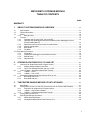
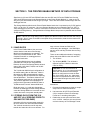
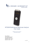
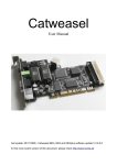
FIGURE 1.2-1. Storage Module and SC12 Cable
1.2 PHYSICAL DESCRIPTION
The Storage Module is housed in a sealed
stainless steel canister with a single 9-pin Dconnector. The Storage Module is connected to
a datalogger via the SC12 9-Pin Peripheral
Cable.
The SM192 and SM716 are identical except for
the amount of memory they contain. The
SM192 has a CPU card with six 32k RAM chips,
providing 192,896 bytes of storage. The SM716
contains the CPU card plus a memory
extension card with 16 additional 32k RAM
chips. Total storage capacity in the SM716 is
716,672 bytes.
1.3 POWER
1.3.1 PRIMARY POWER
The Storage Module is powered by 5 VDC
received from the datalogger or from data
retrieval interfaces such as the SC532, 9-pin
1-2
Peripheral to RS232 Interface, the SM232A
Storage Module - RS232 Interface, or the
PC201 Clock-SIO Tape Read Card. Pin 1 of
the 9-pin D-connector supplies the 5 VDC. Pin
2 is both the power ground and signal ground.
1.3.2 BACKUP POWER
Memory backup power is provided by an
internal 3.5 VDC lithium thionyl chloride battery
when the Storage Module is disconnected from
a primary power source. About 6 years of RAM
backup power can be expected from the lithium
battery at room temperature. Higher
temperatures increase the current drain of the
RAM chips and the self-discharge rate of the
battery while lower temperatures decrease the
battery's capacity, i.e., energy. At 50oC, battery
life will be about 2 years; at -25oC, about 4
years can be expected. If possible, keep the
Storage Module at or near room temperature
when not in use.
SECTION 1. SM192/716 STORAGE MODULE OVERVIEW
Expected
Battery Life
SM192
SM716
@ 25C
@ 50C
@ -25C
about 10 yrs.
about 3 yrs.
about 6 yrs.
about 6 yrs.
about 2 yrs.
about 4 yrs.
NOTE: These figures apply when:
1. The SM is not connected to a primary
power supply (such as a datalogger), and
2. The SM is continuously at one of the
above temperatures.
Meeting these conditions is unlikely in
normal operation.
1.4 FUNCTION
The SM192 and SM716 Storage Modules
provide battery-backed, solid-state, RAM data
storage to supplement the storage capacity in a
datalogger. The Storage Modules can store
data from all Campbell Scientific, Inc.
dataloggers and from other devices which
properly enable them.
All Storage Module operations occur in one of
three basic operational modes:
1. Interactive communication with
datalogger for data and program
storage and retrieval.
2. The Printer Enable Method for data
storage with the 21X and CR7 with
older PROMS, the CR21, the DSP4,
and non-datalogger devices.
3. The Telecommunications Command
State for data retrieval and other
miscellaneous operations.
The SM can store data either under program
control (Instruction 96) or under user control (*8
Mode with CR10, *9 Mode with 21X and CR7).
Datalogger programs can be stored in and
retrieved from the Storage Module using the *D
Mode. The CR10 *9 Mode enables the user to
directly execute commands such as: check
battery, change address, view data, etc.
(Appendix A).
1.4.2 OPERATION WITH DATALOGGERS WITH
OLDER PROMS AND NON-DATALOGGER
DEVICES (PRINTER ENABLE METHOD)
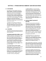
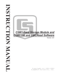
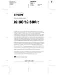
In the Printer Enable Method (Figure 1.4-2), the
Storage Module stores all data received (on pin
9) while the printer enable line (pin 6) is high.
The Storage Module baud rate must be set to
match that of the sending device (Section
1.4.5). The datalogger cannot detect if the SM
is connected. Data are sent whether or not the
SM is connected.
Data can be stored in the SM under program
control (Instruction 96 or *4) or under user
control (*9 Mode). Operations with the CR21,
the DSP4 Heads Up Display and with nondatalogger devices (Appendix C) are also
accomplished through the Printer Enable
Method (Section 3).
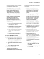
1.4.3 DATA RETRIEVAL/TELECOMMUNICATION
COMMAND STATE
Data retrieval and other interactive operations
with a computer take place in the
Telecommunications command state (Figure
1.4-3). TELCOM (PC208 software) uses the
Telecommunications Commands for data
retrieval, data storage, storage and retrieval of
datalogger programs, SM software switch
setting, status checks, battery tests and other
functions (Section 5). The commands used by
TELCOM are described in Appendix D.
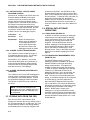
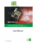
1.4.1 OPERATION WITH CURRENT CR10, 21X,
AND CR7
Storage Module operations with the current
versions of the CR10, 21X, and CR7 are
accomplished through the use of an interactive
command structure with handshaking (Figure
1.4-1). If the SM is not connected, the
datalogger will not send data. The datalogger
detects when the SM is connected, and sends
the backlogged data the next time it executes
Instruction 96.
1-3
SECTION 1. SM192/716 STORAGE MODULE OVERVIEW
Figure 1.4-1 Operation with Current CR10, 21X, and CR7
Figure 1.4-2 Printer Enable Operations
Figure 1.4-3 Telecommunications Command State
1-4
SECTION 1. SM192/716 STORAGE MODULE OVERVIEW
1.4.4 MEMORY CONFIGURATION
The Storage Module's memory can be
configured as either Fill and Stop or Ring style
memory. In the Fill and Stop configuration, the
Storage Module stops accepting data when its
memory is full. No data write-over occurs. In
the Ring Memory configuration (the default
setting), new data continue to be stored even
after the memory is full. New data are written
over the oldest data in the memory. The
Storage Module's memory configuration can be
changed using SMCOM or with Command 4 in
the CR10 *9 Mode.
1.4.5 BAUD RATES
When storing CR7, CR10, and 21X data, the
Storage Module is set for its default baud rate of
76,800/9600; baud rate matching is automatic
and requires no user intervention. Data transfer
takes place at 9600 baud.
With other devices, the baud rates of the device
and the Storage Module must be matched by
the user. Storage Module choices are: 300,
1200, 9600, 76,800, and 76,800/9600 (Section
4.1). With the CR21, the SM must be set to 300
baud. When using the Telecommunications
Commands, sending several carriage returns
will cause the Storage Module to match the
computer's baud rate (300, 1200, or 9600
baud).
1.4.6 FILE MARK
File Marks are used to separate data in the
Storage Module. A File Mark is automatically
placed in the SM's memory when the SM is
connected to a power source (datalogger or
retrieval interface) or when the datalogger
compiles a program containing Instruction 96.
For example, if the user has retrieved data from
one datalogger, disconnects the SM and then
connects it to a second datalogger, a File Mark
is placed in the data when the second
datalogger is connected. This mark follows the
data from the first datalogger and precedes the
data from the second.
A File Mark can be placed in the data from
SMCOM or the CR10 *9 Mode Command 3.
The Storage Module will not store back to back
file marks; if a File Mark is the last thing stored
in memory, a second file mark will not be
stored.
1.5 QUICK START-UP PROCEDURE
This Section describes the basics of storing and
retrieving of datalogger data. These operations
are discussed in detail in Sections 3, 4, and 5 of
this manual.
1.5.1 PREPARATION
Before putting the Storage Module into service,
connect it to a computer and use SMCOM to
reset the SM and test its battery.
If it is not possible to use a PC compatible
computer and SMCOM, the user must establish
communication between the SM, the available
computer, or terminal (Section 5) and reset the
SM using the Telecommunications Commands
(Appendix D) or use the *9 Mode in the CR10
(Appendix A).
1.5.2 PROGRAM THE DATALOGGER TO SEND
DATA TO THE SM
Instruction 96 is used in the datalogger program
to send data to the Storage Module. The SM is
connected to the datalogger with the SC12
cable. Each time Instruction 96 is executed,
Final Storage data accumulated since the last
transfer are sent to the Storage Module.
For the CR7 and 21X WITHOUT Instruction 96
the *4 Mode is used to enable output to a
printer. The CR21 automatically outputs printer
data at 300 baud each time data is sent to Final
Storage.
The DSP4 outputs printer data when the printer
function is enabled.
1.5.3 MANUAL DUMP
The *8 Mode in the CR10 or the *9 Mode in the
21X and CR7 can be used to transfer data to
the SM under keyboard control. All of the
above options are discussed in greater detail in
Section 4.
1.5.4 DATA RETRIEVAL
The simplest method of retrieving data from the
Storage Module is to use SMCOM. SMCOM is
contained in Campbell Scientific's PC208
software. It is written for IBM PC/XT/AT/PS-2's
and compatibles. If the user has another type
of computer, the SM telecommunications
commands can be used to retrieve the data.
Data retrieval (including interface devices) is
discussed in Section 5.
1-5
SECTION 2. STORING DATA FROM CR10, 21X, AND CR7
This section covers data storage from the CR10 and from the 21X and CR7 with current software. 21X
Microloggers released after February 1989, and CR7 dataloggers released after August 1991, contain
the OSX and OS7 Series PROMS which support two major SM functions that earlier versions do not:
1. Datalogger programs can be stored and retrieved in the *D Mode.
2. Instruction 96, transfer of binary Final Storage data to the SM, will not send data until the SM is
connected. In older versions of the 21X and CR7 PROMS, the Instruction 96 transfer is simply an ASCII
printer dump. Data are sent regardless of whether the SM is or is not connected.
See Section 3 for earlier PROM versions of the 21X and CR7.
2.1 INSTRUCTION 96 -- OUTPUT DATA
UNDER PROGRAM CONTROL
Instruction 96 is used to send Final Storage
data to a Storage Module under program
control. Instruction 96 should be entered into
the program table following the Output
Processing Instructions. Instruction 96 should
be executed each time the table is executed
(i.e. the program should not branch around or
skip over Instruction 96).
Instruction:
96
Parameter: 01: 7X - CR10 option 7X sends
the data to the Storage
Module with address "X".
X=1-8
30 - 21X and CR7 use option
code 30 to send data to
Storage Module.
When output to the Storage Module is enabled
with Instruction 96, the Storage Module(s) may
either be left on-site and periodically
exchanged, or brought to the site to milk the
data from the datalogger.
When the user finally does connect the Storage
Module to the datalogger, two things happen:
1. Immediately upon connection, a File Mark is
placed in the Storage Module Memory at
the position of the Module's Storage
Reference Pointer (SRP). The File Mark
allows the operator to distinguish blocks of
data from different dataloggers or from
different visits to the field.
2. During the next execution of Instruction 96,
the datalogger recognizes that the Storage
Module is present, outputs all of the data
stored since the previous output, and
updates the Storage Module Pointer to the
DSP location. This transfer occurs in binary
at 9600 baud.
Under optimum conditions, the datalogger
outputs 480 low resolution data points per
second; a full 64K CR10 takes over one minute
to complete the data transfer. If the execution
interval is less than one minute, the data
transfer will be interrupted and will take longer
to complete.
The datalogger is capable of recognizing
whether or not the Storage Module is
connected. Each time Instruction 96 is
executed and there is data to output, the
datalogger checks for the presence of the
Storage Module. If one is not present, no data
are sent; the datalogger continues its other
operations without advancing its Storage
Module Pointer.
2-1
SECTION 2. STORING DATA FROM CR10, 21X, AND CR7
CAUTION: Be sure to complete the data
transfer before making any changes in the
datalogger program. Changing a program
and then compiling it will advance the
datalogger's Storage Module Pointer to the
position of the DSP. If this is done before
connecting the Storage Module to allow the
datalogger to transfer the data, the old data
will NOT be automatically transferred to the
Storage Module. Also, the Instruction 96
data transfer will not take place while the
datalogger is in communication with another
device, e.g. a computer or an active
CR10KD.
To be certain that the SM has been connected
during an execution of Instruction 96, the user
can:
1. Leave the SM connected longer than
the execution interval of the Program
Table that includes Instruction 96, or
2. Use the SC90 9 pin Serial Line Monitor.
The SC90 contains an LED which lights
during data transmission. The user
connects the SM to the datalogger with
the SC90 on the line and waits for the
LED to light. WHEN THE LED GOES
OFF, data transfer is complete and the
SM can be disconnected.
To avoid data loss, data must be retrieved
before the datalogger's ring memory wraps
around and begins to write over the oldest data.
2.1.1 MULTIPLE STORAGE MODULES WITH
CR10
The CR10 uses synchronous addressing to
communicate with multiple peripherals (CR10
Manual, Sections 6.2 and 6.6). Up to 8 Storage
Modules can be connected to a single CR10.
Each is assigned an address, 1 through 8.
Addresses are assigned in the *9 Mode
(Command 10), or in the Telecommunications
Command State (the L Command). These are
discussed in Appendixes A and D of this
manual, respectively. The default Storage
Module address on reset (as sent from the
factory) is #1. This will be sufficient for most
users.
2-2
At a given time, only one Storage Module will
execute commands directed to SM #1. If there
is no Storage Module with address #1, the
Storage Module with the lowest numbered
address will execute the commands sent to SM
#1. Commands directed to addresses other
than #1 can be executed ONLY by the SM with
the correct address. Do NOT connect Storage
Modules with the same address to a CR10 at
the same time.
If only one Storage Module is used with the
CR10, its address should be #1. When multiple
Storage Modules are used in a CR10 system,
each should be assigned its own address and
set to Fill and Stop. Instruction 96 is used in the
CR10 program to send data to Storage Module
address #1. The lowest numbered Storage
Module will fill up first, followed by the next
lowest address, and so on. Alternatively, data
can be sent to specific Storage Modules via
direct addressing by the CR10 (using a
separate Instruction 96 for each SM).
Instruction 96 can be entered two or more times
in a program to sort data to specific Storage
Modules. Three important considerations are:
1. All Storage Modules to be used must be
connected to the CR10 with SC12
cables.
2. Time must be allowed between the
execution of multiple 96 commands to
Storage Modules. Add 5 msec to the
time it takes to store the number of
bytes to be transmitted (1 msec per
byte) before executing the next
Instruction 96 which addresses a
different Storage Module.
3. Use of the keyboard or
telecommunications during the
execution of the Instruction 96 may
backlog the data to be sent to the
Storage Modules. In this event, during
the next execution of Instruction 96 all
backlogged data will be sent to the
Storage Module addressed in that
instruction.
SECTION 2. STORING DATA FROM CR10, 21X, AND CR7
2.1.2 USE OF TWO STORAGE MODULES WITH
21X OR CR7
For large volumes of data, two SMs can be
connected to the 21X or CR7. Use SMCOM to
set one SM as Fill and Stop, and the other as
Ring Memory.
2.2 *8 AND *9 MODE -- KEYBOARD
INITIATED DATA TRANSFER
2.2.1 *8 MODE - CR10
The *8 Mode is used to manually initiate a Final
Storage Data transfer from the CR10 to an
external peripheral. Data transfer rate is 9600
baud. Refer to the discussion of the *8 Mode
(Section 4.2) in the CR10 Operator's Manual for
full details.
2.2.2 *9 MODE - 21X OR CR7
The F*9 Mode in the 21X and CR7 dataloggers
is used to transfer a specified block of data from
Final Storage to the Storage Module. Consult
the appropriate datalogger manual for details.
This function is different from the *9 Mode in the
CR10.
BURST data is output by the datalogger in a
unique format which includes calibration
measurements at the beginning and end of the
series of measurements. SPLIT will translate
this BURST data. (Section 4.3.1 in the PC208
manual.)
2.3.1 BURST DATA WITH CR10
The CR10 requires a special PROM to use the
BURST Measurement Instruction (23). Keying
a "3" in the second digit from the right in
Parameter 04 of Instruction 23 selects the
Storage Module as the destination of the
BURST data. All SM's connected should be set
to Fill and Stop and have consecutive
addresses. The BURST data will be sent to the
first available (lowest addressed) Storage
Module, followed by the next lowest addressed,
and so on.
2.3.2 BURST DATA WITH 21X
To send BURST Measurement (Instruction 23)
data to the Storage Module from the 21X, set
the Destination option (Parameter 04) to 2 for
Serial port output at 76,800 baud.
2.3 STORING BURST MEASUREMENT
DATA FROM THE CR10 OR 21X
The BURST Measurement is a special
datalogger instruction used to make high rate
analog voltage measurements. Two options
are available for data retrieval with this
instruction: 1) Data are stored in datalogger
Input Storage Locations or 2) Raw data are sent
out the datalogger serial port. In the second
case, the Storage Module can capture the data
at 76,800 baud.
2-3
SECTION 3. THE PRINTER ENABLE METHOD OF DATA STORAGE
Data from the 21X and CR7 with PROMS older than the OSX and OX7 series PROMS and from the
CR21 and DSP4 are stored in the Storage Module via the Printer Enable Method, i.e., data on the TD
line (pin 9) are stored while the PE line (pin 6) is high. This is also the method of data storage with nondatalogger devices.
The Storage Module defaults to the Printer Enable Method each time it is powered up by 5 VDC applied
to Pin 1 of its 9-pin "D" connector. Up to two Storage Modules can be connected to the 21X, CR7, or
CR21 dataloggers at one time. If two are connected, one should be set to Fill and Stop, and the other
configured as Ring Memory. Storage Module-to-Storage Module dumps are not possible with the Printer
Enable Method.
NOTE: If the PE line is high when power is applied, the SM will not store data until the next time PE
goes high. Also, if power to the SM is interrupted during a transmission, data since the last time PE
went high will be lost.
3.1 BAUD RATES
In the Printer Enable Method, the user must
ensure that the baud rates of the Storage
Module and the datalogger are matched. The
CR21 has a fixed baud rate of 300. Other
Campbell Scientific Inc. dataloggers have
selectable baud rates.
The Storage Module baud rate is software
selectable, and may be set using SMCOM.
Data can be sent to the Storage Module at baud
rates of 300, 1200, 9600, 76,800, and 76,800with-9600-fall back.
The 76,800-with-9600-fall back configuration is
the default setting after an SM reset. When in
this setting, the SM can automatically change
from capturing data at 76,800 baud to capturing
data at 9600 baud. This feature allows the use
of two different baud rates in a single program.
The practical application of this would be in a
program which generates both BURST data at
76,800 baud and "normal" data at 9600 baud.
Baud rate errors, i.e., baud rate mismatches
between the datalogger and the Storage Module,
cause the Storage Module to increment its error
counter and enter a low power standby state.
3.2 STORING DATA FROM THE 21X
AND CR7 (ALL VERSIONS PRIOR TO
OSX AND OS7 RELEASE)
Instruction 96 is the recommended method for
the CR7 and the 21X with Extended Software.
The *4 Mode can also be used for this data
transfer but Instruction 96 is more efficient. For
large volumes of data two SMs can be
connected to the datalogger. Use SMCOM to
set one as Fill and Stop, and the other as Ring
Memory.
There are two additional methods of outputting
printer data to the SM from the 21X and CR7:
1. The *4 Mode
2. The *9 Mode (NOTE: This *9 Mode is
different from the *9 Mode in either the
CR10 or CR21).
CAUTION: Do not use Instruction 96
(ASCII option), *4 or *9 to output arrays with
more than 100 elements if the Storage
Module is configured to encode the data.
The 101st, 201st, 301st, etc., data points
will each be interpreted as a start-of-array
and the data following these points will be
meaningless.
Alternatives:
1. Program the datalogger such that no output
array has more than 100 elements.
2. Use Instruction 96 (CR7X and Extended
21X) to output the data in Final Storage
Format so no encoding takes place.
3. Disable the encode option and store data
as is, in ASCII. However, this uses 6 times
as much memory as Final Storage Format.
3-1
SECTION 3. THE PRINTER ENABLE METHOD OF DATA STROAGE
3.2.1 INSTRUCTION 96 - OUTPUT UNDER
PROGRAM CONTROL
Instruction 96, available in the CR7X and in the
Extended Software PROMs for the earlier
versions of the 21X, is used to send Final
Storage data to the Storage Module under
program control. Instruction 96 should follow
the Output Processing Instructions in the
program table. Consult the datalogger manual
for details about using Instruction 96. Do NOT
use both the *4 Mode and Instruction 96 to
activate a device in a datalogger program.
Instruction:
96
Parameter:
01:22
Explanation:
Option 22 selects binary
printer output at 9600 baud.
The left digit specifies the
device option and the right,
the baud rate. Refer to the
datalogger manual for details.
3.2.2 *4 MODE - OUTPUT DEVICE ENABLE
The *4 Mode is used to enable the output of
Final Storage data to a printer. The Storage
Module will capture this printer output.
Select option "X1" in window 1, and set the
baud rate at 9600 (option 02) in window 2 (to
match the Storage Module's default setting).
Data are written to the Storage Module each
time data are sent to Final Storage.
3.2.3 *9 MODE - KEYBOARD INITIATED DATA
TRANSFER
The *9 Mode in the 21X and CR7 dataloggers is
used to transfer a specified block of data from
Final Storage to the Storage Module. Consult
the appropriate datalogger manual for details.
This function is different from the *9 Mode in
the CR10.
NOTE: The baud rate settings for the
datalogger (set in the *4 Mode) and for the
Storage Module (set from SMCOM) must
be compatible.
3.3 STORING DATA FROM THE CR21
Each time the CR21 outputs data to Final
Storage, the data are also sent (in ASCII) to pin 9,
the TD (transmit data) line, at 300 baud. So, Final
Storage data are written to the Storage Module
automatically when it is properly configured and
3-2
connected to the CR21. Use SCOM to set the
Storage Module baud rate to 300 to collect CR21
data. The Encode/Decode switch should be set to
Encode (default). To backlog CR21 data while it is
temporarily disconnected from the Storage
Module, enter the *9 Mode (in the CR21). When
the Storage Module has been re-connected, reenter the *0 Mode. Refer to the CR21 Manual for
details.
3.4 SPECIAL DATA STORAGE
OPERATIONS
3.4.1 DSP4 HEADS UP DISPLAY
In addition to real-time monitoring of datalogger
measurements, the DSP4 Heads Up Display
can be used with the CR10, 21X, and the CR7
dataloggers to store and retrieve data and
programs. With the DSP4 printer function
enabled, datalogger Final Storage data can be
sent to the Storage Module in ASCII at either
300 or 1200 baud or at 9600 baud in Final
Storage Format. Refer to the DSP4 Instruction
Manual for more details regarding the Printer
Options.
3.4.2 STORING BURST MEASUREMENT DATA
FROM THE 21X
The BURST Measurement is a special
datalogger instruction available in an optional
software PROM to make high rate analog
voltage measurements. Two options are
available for data retrieval with this instruction:
1) Data are stored in datalogger Input Storage
Locations or 2) Raw data are sent out the
datalogger serial port. In the second case, the
Storage Module can capture data at 76,800
baud. This can occur in the default baud rate
setting or the Switch settings can be configured
to 76,800 baud (L command, Appendix D).
When the BURST Measurement (Instruction
23) is used with the 21X, select the Destination
(Parameter 04) option as 2 for Serial port output
at 76,800 baud to send data to the Storage
Module. BURST data is output by the
datalogger in a unique format which includes
calibration measurements at the beginning and
end of the series of measurements. SPLIT will
translate this BURST data (Section 4.3.1 in the
PC208 Manual).
SECTION 4. STORAGE MODULE MEMORY AND DATA ENCODING
4.1 FILE MARKS
File Marks are used to separate data in the
Storage Module. A File Mark is automatically
placed in the SM's memory when the SM is
connected to a power source (datalogger or
retrieval interface) or when the datalogger
compiles a program containing Instruction 96.
For example, if the user has retrieved data from
one datalogger, disconnects the SM and then
connects it to a second datalogger, a File Mark
is placed in the data when the second
datalogger is connected. This mark follows the
data from the first datalogger and precedes the
data from the second.
A File Mark can be placed in the data from
SMCOM or the CR10 *9 Mode Command 3.
The Storage Module will not store back to back
file marks; if a File Mark is the last thing stored
in memory, a second file mark will not be
stored.
4.2 POINTERS
The SM has several internal pointers which are
used to keep track of data for both storage and
retrieval operations.
The Display Location Pointer (DLP) is used to
display Storage Module data. Ordinarily, when
the SM is connected to a datalogger, the DLP
will be at the beginning of the current file. The
DLP can be positioned anywhere within the
data, using the nnnnnnG command (Appendix
D). Data can then be "dumped" to the user
device using one of the appropriate commands
(nnnnC, nnnnD, or nnnnF). The dump will
begin at the DLP and continue until it reaches
the Storage Reference Pointer (SRP) or until
the next File Mark.
The Storage Reference Pointer (SRP),
indicates the next location to be written to in the
Storage Module. If not changed by user
commands, it will always be at the end of data
in the Storage Module. It can be moved
through use of the 3H command (Appendix D),
however, this can be dangerous since the next
data written to the Storage Module will write
over data at the SRP. Typically, the 3H
command is used only during testing.
The Dump Pointer is an internal Storage
Module pointer used for keeping track of the
current start-of-dump for Storage Module-to
Storage Module data dumps and for the data
retrieval options of the SMCOM program. The
user can move the Dump Pointer with the 4H
command (Appendix D). The Dump Pointer
marks the end point of the previous data dump
and thus the start-of-dump location for the next
dump. Moving this pointer "loses" this
reference point, which can cause problems with
subsequent dumps.
4.3 DATA FORMAT AND INPUT
BUFFER
Data can be stored in either the Campbell
Scientific Inc. Final Storage Format (binary) or
in the Printable ASCII format. The default
setting of the Storage Module is to encode
ASCII data into binary; one low resolution data
point requires two bytes. Storing ASCII data
requires 10 bytes per data point. The encode
option can be disabled by a software switch
(see Telecommunications Commands,
Appendix D). Each asynchronous byte is 8-bits
plus 1 start and 1 stop bit. The idle state (stop
bit) is 0 VDC. RS-232C logic levels, if applied,
are clipped to 0 and 5 VDC.
The Storage Module has a 2800 byte Input
Storage buffer. Data transmissions of any
length can be stored at 9600 baud (or slower),
allowing only 5 msec between transmissions for
"housekeeping" tasks. A transmission is
defined here as all data sent to the Storage
Module at one time while PE is high.
When sending data at 76,800 baud, a continuous
transmission must not be larger than about 7500
bytes, or the input buffer will be overrun and data
will be lost. In addition, if a second transmission
occurs before the previous transmission's data
have been processed and stored, all data in the
previous and the current transmission will be lost.
The maximum possible data storage rate is
approximately 5600 bytes each second (2800
low resolution data points). Transmissions of
data at 76,800 baud must be broken up into
segments small enough to stay within this limit.
Processing time required by the Storage
Module for each byte is 210 usec while
4-1
SECTION 4. STORAGE MODULE MEMORY AND DATA ENCODING
receiving data plus 110 usec for each byte
remaining in the input buffer after transmission
is complete. As an example, it takes 130 msec
to transmit 1000 bytes at 76,800 baud. The
Storage Module has time to store 619 bytes
(130 msec divided by 210 usec/byte) before the
transmission has ended. That will leave 381
bytes in the input buffer when the PE line drops.
The SM will take 42 msec (381 bytes times 110
usec/byte) plus 5 msec overhead to process
and store the remaining bytes. This results in a
total of 177 msec to receive and store 1000
bytes at 76,800 baud.
Bytes from the Storage Module input buffer are
permanently stored in byte-pairs. The Campbell
Scientific Inc. dataloggers' Final Storage Format
data are always grouped in pairs. Printable
ASCII and general purpose data transmissions
may have a single byte left in the input buffer
when the PE line drops. In this case, the byte is
left in the input buffer until another transmission
occurs. It will be paired with the first byte and
stored in permanent storage with the current
data.
If a single byte remains in the input buffer when
power is disconnected from the Storage
Module, it will be stored with a null character
(ASCII Code O) as the second byte the next
time external power is applied. A File Mark is
stored at power-up. If there is an added null
character, it will be placed before a File Mark.
4-2
SECTION 5. DATA RETRIEVAL
Data retrieval is accomplished on PCs using SMCOM. Other computers require a software program
which makes use of the Storage Module Telecommunications Commands (Appendix D). This process
requires both a hardware interface and a software program.
5.1 HARDWARE
There are four interfaces which enable
communication between a computer and the
Storage Module:
1. The SC532 Peripheral to RS232 Interface
2. The PC201 Tape Read, Clock, Serial I/O
Card (requires SC209 cable)
3. The CR10 (not possible with other
dataloggers)
4. The SM232A Storage Module RS232
Interface
The PC201 Card functions ONLY with IBM
PC/XT/AT's and compatibles. The SC532 can
function with any computer having an RS232
port BUT both the PC201 and the SC532
require a software program to raise the CLK/HS
and PE lines (by raising pins 20 and 4,
respectively, on the computer) in order to
activate the SM (Section 5.2). SMCOM
program performs this function automatically.
The SM232A functions with any RS232
computer or terminal which raises the DTR line
when powered up.
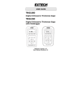
5.1.1 SC532
A standard 25-pin ribbon cable links the SC532
to the computer's 25-pin serial port. If the
computer has a 9-pin serial port, a 9-pin to 25pin adaptor cable is required. Campbell
Scientific Inc.'s SC12 9-pin ribbon cable links the
Storage Module to the SC532 (Figure 5.1-1).
The SC532 requires 12 VDC (nominal) which is
usually furnished by plugging the AC/DC adaptor
unit into a standard 120 VAC outlet. The use of
battery power is possible and is described in the
SC532 manual.
5.1.2 SC209/PC201
The SC209 - Storage Module connector cable
(available from Campbell Scientific Inc.) links
the 9-pin port on the Storage Module to the 34
pin connector on the PC201 card (Figure 5.1-2).
5.1.3 VIA CR10
The Storage Module is linked to the CR10 by
the SC12 cable. SCOM establishes
communication between the computer and the
CR10 over direct cable or telecommunication
link (Figure 5.1-3).
5.1.4 SM232A
The AC adaptor is plugged into a 120 VAC
outlet. The serial port of the terminal/computer
is connected to the "TO TERMINAL" connector
on the SM232A with a 25-pin cable. An SC12
9-pin ribbon cable, links the Storage Module to
the "TO STORAGE MODULE" connector on the
SM232A. The central toggle switch is placed in
the "DATA TO TERMINAL AND MODEM"
position; the other toggle switch in the
"TRANSPARENT" position. (Figure 5.1-4).
5.2 SOFTWARE
SMCOM (PC208 Software) is used with IBM
PC/XT/AT/PS-2 or compatibles. It functions
with any of the hardware interfaces listed in
Section 5.1. SMCOM automates the storage
and retrieval of data and programs and also has
a terminal emulator for the manual execution of
telecommunications commands.
5-1
SECTION 5. DATA RETRIEVAL
5.1-1 Storage Module Connected With SC532
5.1-2 Storage Module Connected to PC201 Card
5.1-3 Communication Via the CR10
5.1-4 Storage Module Connected With SM232A
5-2
SECTION 5. DATA RETRIEVAL
Complete details on the operation of SMCOM
are contained in the PC208 manual.
When using a computer other than an IBM
PC/XT/AT/PS-2 or compatible, the SM232A
is the recommended interface. It has a
manually operated switch to raise the
Storage Module's PE and CLK/HS lines.
Thus the user's program doesn't need to
raise pins 4 and 20 on the computer (as is
necessary with the SC532 Interface). With
the SM232A and a commercially available
terminal emulator program the user may
manually execute the telecommunications
commands to retrieve data to disk.
However, when this method is used to
retrieve large data files, there is a risk of
overrunning the computer's input buffer and
losing data. To prevent this, the user can do
one of the following.
1. Select a terminal emulator program which
has X-ON, X-OFF capability.
1. Make the connections between the
SM232A and the computer/terminal as
shown in 5.1-4. Refer to the SM232A
Instruction Manual for further details.
Enable X-ON, X-OFF in the terminal
emulator.
2. Place the toggle switch on the SM232A
in the TRANSPARENT position. This
switch should be left in this position until
the Data Terminal Ready (DTR) line of
the terminal/computer is raised high. In
the case of a terminal, this happens
when the terminal is powered,
connected to the SM232A, and set to
receive 8-bit (plus 1 start / 1 stop bit)
data at a valid baud rate. In a computer,
executing a terminal emulator program
drives DTR high under software control.
2. Use the C, D or F command to have the
Storage Module send the data in blocks
small enough to avoid this problem.
3. Once DTR is high, move the switch from
TRANSPARENT to UNLOAD (raising
CLK/HS and enabling PE), which
activates the Storage Module.
3. Write a program which requests the data
in blocks small enough to avoid the
problem.
4. Send several carriage returns to
synchronize baud rates and receive the
Storage Module prompt: CR, LF, %.
4. Select a baud rate slow enough for the
computer to keep up with the data.
5. Type in the appropriate
telecommunication commands
(Appendix D) to collect the desired data
file(s). (Prior to sending the last carriage
return to execute the C, D, or F
command, place the terminal emulator
in the receive a file mode.)
5.3 DATA RETRIEVAL STEPS
5.3.1 IBM PC/XT/AT/PS-2'S AND COMPATIBLES
a. With IBM PC/XT/AT's and compatibles, use
either the PC201, SC532 or SM232A. The
IBM PS-2 will not accept the PC201 Card
but is compatible with the SC532.
b. Make the appropriate connections (Section
5.1).
c.
that the terminal emulator software has X-ON, XOFF capability.
Execute SMCOM (PC208 manual).
5.3.2 NON-IBM COMPATIBLES
The telecommunications commands are
used here to:
a. Position the DLP (Display Location
Pointer) at the desired beginning
point of the data transfer (one of the
G commands).
b. Collect the desired file(s) using the C,
D, or F command.
The following instructions apply to a
configuration using a terminal emulator program
and the SM232A. It is assumed for this example
5-3
SECTION 5. DATA RETRIEVAL
6. Send the last carriage return to execute
the data retrieval.
The same fundamental procedures used in a
manually executed data transfer form the basis
of SMCOM's data retrieval options. They can
also be employed in a user-written program to
automate data retrieval for non-IBM compatible
computers.
Appendix B contains a sample flow diagram. It
can serve as the basis for a user-written data
retrieval program.
5-4
5.3.3 CR10 TELECOMMUNICATIONS
INTERFACE
Make the connections (Figure 5.1.3) and
establish communications with the CR10. Send
the command "XM,CR" to the CR10 (where X is
the Storage Module address 1...8). If the
connections are correctly made and the Storage
Module is properly addressed, it will send back
"CR, LF, %." If the attempt to establish
communications fails, the CR10 will return "*".
Once the "%" is received, the Storage Module
telecommunications commands (Appendix D)
may be used as described above. SMCOM
may be used when the connection to the CR10
is through the SC32A Optically Isolated R5232
Interface.
SECTION 6. STORING AND RETRIEVING DATALOGGER PROGRAMS
CR10, 21X, and CR7 programs can be uploaded and downloaded between the datalogger and the
Storage Module in the *D Mode. (OSX and OS7 series PROMS required for 21X and CR7.) SMCOM
(or telecommunications commands) allows programs to be transferred between the computer and the
SM. Using these capabilities, a program can be developed in the computer, stored in the SM, and then
carried to the field and downloaded to the DATALOGGERS.
The SM can store up to 8 programs. They are numbered 1 through 8 and are protected against being
written over by data.
With the release of the OS series PROMS (OS10, OSX, OS7), the DATALOGGERS were given the
capability of automatically loading program 8 if the Storage Module were connected to the datalogger
when the datalogger is powered on.
21X and CR7 PROMS prior to the current OSX and OS7 versions do not have the capability to store and
directly load programs from the SM. Programs may be transferred via DSP4 Heads Up Display (Section
6.3).
6.1 *D MODE - WITH DATALOGGER
The *D Mode is used to transfer programs
between the datalogger and Storage Module.
The commands in Table 6.1-1 are used to save,
retrieve, or clear programs from the Storage
Module. See the appropriate datalogger
manual for further details on the *D Mode.
TABLE 6.1-1 *D Mode Keyboard
Commands
Key
Display
Description
*D
7XA
1YA
13:00
7X:00
Enter *D Mode
Address Storage Module X
Store Program in SM as
Y(Y=1..8)
Load Program Y from SM
Erase Program Y from SM
command completed
2YA
3YA
13:0000
The program is stored, retrieved, or erased by
referring to a program number (1...8) in the
Storage Module. If a program to be retrieved
does not exist in the Storage Module, the error
message "E99" will be displayed. After a
program is erased the space becomes available
for data storage.
6.2 SMCOM - WITH COMPUTER
SMCOM has options to automatically store,
retrieve, and erase datalogger programs. If you
cannot use SMCOM, the Storage Module
telecommunications commands are described
in Appendix D.
6.3 USING DSP4 HEADS UP DISPLAY
TO STORE AND RETRIEVE
DATALOGGER PROGRAMS
In addition to real-time monitoring of datalogger
measurements, the DSP4 Heads Up Display
can be used with the CR10, 21X (including preOSX versions with Extended Software) and the
CR7 dataloggers to store and retrieve data and
programs. The DSP4 Load and Save program
commands will allow loading and saving CR10,
21X, and CR7 datalogger programs in the
Storage Module.
The DSP4 Flag buttons 1...8 will execute the
Load or Save command using the Storage
Module as the medium. Up to 8 datalogger
programs can be saved at one time in the
Storage Module. The program to be saved or
loaded is selected by pressing the appropriate
push button switch. Refer to the DSP4
Instruction Manual for more details.
The 21X or CR7 must have only one
Storage Module connected when storing
and retrieving programs.
6-1
APPENDIX A. CR10 *9 MODE -- STORAGE MODULE COMMANDS
The CR10 *9 Mode is used to issue commands
to the Storage Module using the CR10KD
keyboard/display or a terminal/computer.
These "commands" are analogous in many
respects to the datalogger functional (*) Modes.
For example, command 7 is used to review
stored data, and 8 is used to transfer data
between two Storage Modules connected to a
CR10.
The key sequences for the *9 commands have
a generalized format. Using Command #1 as
an example:
KEY DISPLAY
EXPLANATION
*9
X
09:01
09:X
A
9X:00
1
9X:1
A
01:0000
248
01:248
A
01:
Enter *9 Mode
Key in the address (x=1
through 8) of the SM to be
given the command.
Enter the SM address, x;
ready to accept a command.
Key in Command #1,
Reset SM.
Enter Command #1. Ready
for instruction to effect
Command #1.
Key in 248 to effect
Command #1.
Execute SM Reset.
After about 1 minute with the SM192 or 4
minutes with the SM716, the number of good
RAM chips will be displayed:
01:06
01:22
6 RAM chips in SM192
22 RAM chips in SM716
Most commands have at least one response.
Advance through the responses and return to
9X:00 (ready to accept another *9 command) by
keying "A". Exit the *9 Mode by keying "*" and
the character of the mode you want to switch to
("*0" to go to the log mode).
TABLE A.1. *9 Commands for Storage Module
COMMAND
DISPLAY
DESCRIPTION
1
01:0000
RESET, enter 248 to erase all data and programs and reset
pointers. While erasing, the SM checks memory.
01:XX
The number of good chips is then displayed (6 for SM192, 22
for SM716). The time required to reset an SM192 is
approximately 60 seconds; SM716 takes nearly 4 minutes.
3
03:01
INSERT FILE MARK, at the position of the SRP if a file mark
wasn't the last thing placed in the data. 1 indicates that the
mark was inserted, 0 indicates that it wasn't.
4
04:XX
DISPLAY/SET MEMORY CONFIGURATION, enter the
appropriate code to change configuration 0=ring, 1=fill and
stop.
A-1
APPENDIX A. CR10 *9 MODE - STORAGE MODULE COMMANDS
COMMAND
DISPLAY
DESCRIPTION
01:ABCD
DISPLAY STATUS (A to advance to each window)
Window 1:
5
AB
CD
02:ABCD
AB
C
D
03:A0CD
A
0
C
D
04:X.XXXX
SRP location (chip no.)
Total good RAM chips (1-22)
Window 2:
DLP location (chip no.)
Unloaded Batt. Chk. 0=low, 1=OK
No. of Programs stored (Max=8)
Window 3:
Errors logged (up to 9)
Not Used
Memory Config. (0=ring, 1=fill & stop)
Memory Status (0=not full, 1=full)
PROM signature (0 if bad PROM)
6
06:0X
BATTERY CHECK UNDER 100 OHM LOAD (0=low, 1=OK)
7
07:00
DISPLAY DATA - select the Storage Module Area with the
following codes:
0 Dump pointer to SRP
1 File 1, current file
2 File 2, previous to file 1
3 File 3, previous to file 2
4 File 4, previous to file 3
5 File 5, previous to file 4
7 Display location pointer to SRP
9 Oldest data to SRP
1-5 will loop within file boundaries, 0, 7, 9 allows display to
cross boundaries. If no file is found, the display returns
"07:00". At this point, another file can be entered by entering
the correct code.
Key A to advance to first data. If another location is keyed in,
SM will jump to 1st start of array following that location.
Review data with:
A Advance and display next data point
B Backup one data point
# Display location, C to return to data
#A Advance to next start of Array
#B Backup to start of Array
#D Return to 9X:00
07:XXXXXX
8
08:00
01:XXXXXX
02:XXXXXX
03:XX
A-2
DUMP TO ANOTHER STORAGE MODULE
Select Area as in 7 above
First Loc. in area selected. To alter, enter location of start
dump.
Final Loc. in area selected. To alter, enter location of end
dump.
Enter destination SM address (1 through 8). The end-ofdump location will be shown when the transfer is complete. If
000000 returns, there was an error in transmission.
APPENDIX A. CR10 *9 MODE - STORAGE MODULE COMMANDS
COMMAND
DISPLAY
DESCRIPTION
XXXXXXXX
87654321
DISPLAY ADDRESSES OF CONNECTED SM'S
1 = occupied, 0 = unoccupied
(Addresses 8-1 from left to right)
9
10
10:0X
CHANGE ADDRESS
X is current address, enter yA to change and then display
address where y=1...8.
A-3
APPENDIX B. SAMPLE FLOW DIAGRAM FOR DATA RETRIEVAL
PROGRAM
B-1
APPENDIX C. NON-DATALOGGER APPLICATIONS
All non-datalogger Storage Module operations
are accomplished through the Printer Enable
Method. The Storage Module can store data
from devices other than dataloggers and
computers providing that power and control
requirements are met. Refer to Section C.3 for
information on the pin configuration for the
Storage Module's 9 pin D connector.
C.1 USING TELECOMMUNICATIONS
COMMANDS TO SEND DATA FROM A
COMPUTER TO STORAGE MODULE
Once communication has been established
between the Storage Module and a computer
(Section 5), the 0/H command stores all data on
the Storage Module's transmit data (TD) line
until the PE (pin 6) and CLK/HS (pin 7) lines go
low. This feature is used to transfer a data file
from the computer to the Storage Module.
External power must remain applied for at least
5 milliseconds following data transmission for
"housekeeping." The SM stores 2 bytes at a
time, so if the total number of bytes transmitted
is an odd number, a NULL character will be
added at the end of the transmission.
NOTE: This command is not available
when using the CR10 as the
telecommunications interface to the
Storage Module.
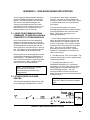
C.2 OTHER NON-DATALOGGER
DEVICES
The Printer Enable Method (Section 4) is used
for non-datalogger SM applications. The PE
line must be low when power is applied or
removed. If a switch is used to enable data
storage, the switch must be debounced. Figure
C.1 depicts debounced circuitry sufficient for
this purpose:
The user should be aware of 3 cases of
transmitting bytes which have special meaning
to the Storage Module in the Printer Enable
Mode. These cases only apply to nondatalogger applications.
1. In the 76,800 with 9600 fall back baud rate
option, the byte 80 HEX must not be the first
byte transmitted at 76,800 baud after the PE
line (Pin 6) goes high. As a first byte, 80 HEX
causes the baud rate to falsely be set at 9600
baud. There is no such restriction when
transmitting at other baud rates. Campbell
Scientific Inc. dataloggers never transmit 80
HEX as the first byte.
2. The HEX byte-pair 7C01 is a File Mark. This
sequence should only be used to separate data
in the Storage Module.
3. The binary byte-triplet 01111101
XXXXXXXX 1XXXXXXX (X = unimportant
information), is a control code reserved by the
Storage Module to mark the beginning of a
stored datalogger program. The "0/F"
telecommunication command (Continuous
Binary Dump) can be used to collect files which
contain this code.
NOTE: The precautions described in
Section 4.5, Data Format and Input Buffer,
apply.
FIGURE C.1 Manual Switch Debounce Circuitry
C-1
APPENDIX C. NON-DATALOGGER APPLICATIONS
C.3 STORAGE MODULE 9-PIN
CONNECTOR
The pins on the 9 pin sub-miniature D
connector on the Storage Module are numbered
1 through 9 on the white plastic base. A
general description of the function of each pin
follows:
Pin 1
(Input) 5 VDC Supply provides power to
the Storage Module. Requires 5 ± 0.4
VDC @ 100 mA. Processor held in
reset when external power falls below
4.6 VDC. Internal battery supplies
memory retention power when external
power drops below 3 VDC. Damage to
SM hardware can occur if input on Pin 1
exceeds 5.5 VDC. Low power standby
mode current drain is about 250 uA.
Pin 2
(Input) Power and signal GROUND.
Pin 3
(Output) RING LINE. Not used.
Pin 4
(Output) RECEIVE DATA (RD) line.
The SM transmits its responses to
Telecommunications commands
asynchronously (0 to 5 VDC) on this
line. Data format is 8-bit, 1 start bit and
1 stop bit. Refer to Section 3.1 for baud
rate options. This line is held high while
the SM is active in the Printer Enable
Method (data storage).
Pin 5
(Input) MODEM ENABLE line. Not
used.
Pin 6
(Input) PRINTER ENABLE (PE) in
Printer Enable Method or
SYNCHRONOUS DEVICE ENABLE
(SDE) line in CR10 Method. If the SM
is externally powered, the PE line is
high (5 VDC) and Pin 7 (CLK/HS) is low
(0 VDC), the processor is set to receive
data asynchronously on Pin 9 (TD).
When the PE line is dropped, data
remaining in the input buffer are stored
and the location pointers are saved.
The processor then enters an inactive,
low power, standby state.
C-2
NOTE: If the processor is still active from a
previous transmission of data and the PE
line is raised again, the processor will be
forced to its inactive state; data from the
previous transmission will be lost and the
current transmission will be ignored.
Normal operation will return with the next
low to high PE transition. Switch bounce on
the PE line can cause the processor to go
inactive after the PE line stabilizes in its
high state.
Pin 7
(Input) CLOCK/HANDSHAKE (CLK/HS)
line. For data storage, CLK/HS must
be low. For data retrieval, using
Telecommunications Commands
(Appendix D) CLK/HS must be high
when the processor is activated by the
PE line going high. CLK/HS must
remain high during
Telecommunications. To exit the
Telecommunications Command State,
lower both the PE and CLK/HS lines.
Pin 8
(Input) TAPE ENABLE line. Not used.
Pin 9
(Input) TRANSMIT DATA (TD) Data is
received by the SM on this line. Data is
received asynchronously ( 0 to 5 VDC)
8-bit, 1 start and 1 stop bit. The idle
state (stop bits) on this line is 0 VDC.
The first byte transmitted to the SM
should be more than 200 microseconds
after the PE line has activated the
processor.
APPENDIX D. TELECOMMUNICATIONS COMMANDS
The SM Telecommunications Commands can
be used over links through the CR10 or with the
Storage Module connected to an interface such
as the SC532, the SM232A, or the PC201.
Establishing communication between the
Storage Module and a computer/terminal is
discussed in Section 5. The commands permit
data storage and retrieval, switch setting, status
checks, battery tests, and other functions.
The Storage Module is ready for a command
when it sends its prompt, <cr><lf> %. The
successful execution of a command is indicated
by the SM returning a <cr><lf> %. (With several
commands, the "<cr> <lf> %" is preceded by
the SM status line as described for the A
command.) If just a "%" is returned, the
command was in error. "Ctrl-S" (XOFF) will
temporarily halt Storage Module responses to
commands; "Ctrl-C" will abort the response. If
using Graph Term or TERM, there may be a
delay for "Ctrl-S" and "Ctrl-C" to take effect due
to the program's buffer capacity.
The descriptions of some commands refer to
the Storage Module pointers (Section 4.2). The
Display Location Pointer (DLP) is used to
display Storage Module data. The Storage
Reference Pointer (SRP), indicates the next
location to be written to in the Storage Module.
The Dump Pointer is an internal Storage
Module pointer used for keeping track of the
current start-of-dump for Storage Module-to
Storage Module data dumps and for the data
retrieval options of the SMCOM program.
Storage Module Telecommunications
Commands are similar to datalogger
Telecommunications Commands and consist of
numbers and CAPITAL letters. In the following
list, Telecommunications Commands are on the
left and their description on the right.
A STATUS: Returns Version number, Switch
settings, number of Programs stored, number
of good Memory chips, number of Errors logged
(max. = 255), number of Available storage
locations, number of locations Full, Storage
Reference Pointer, Display Location Pointer,
and Checksum (sum of all transmitted ASCII
characters since last %; wraps around at 8192
bytes).
Example: V1 S1401 P0 M6 E0 A96448 F1 R2
L2 C1980 is the expected response to the A
command after the SM192 has been reset.
Example: V1 S1401 P0 M22 E0 A358336 F1
R2 L2 C2071 is the expected response to the A
command after the SM716 has been reset.
NOTE: Refer to the L command for a
discussion of the switch settings.
0A INHIBIT STATUS: Returns status line
without carriage return, line feed, and prompt
(%) following. Signature or status is inhibited on
subsequent commands other than A that
normally display signature or status. Command
A restores normal status function.
nnnnB Move the DLP back nnnn output arrays
from its current position. If it is fewer arrays to
the beginning of the file (File Mark), the DLP will
be placed at the beginning. B is the same as
1B. Status is displayed following execution of
command.
nnnnC COMMA DELINEATED ASCII DUMP:
Dump nnnn output arrays from the location of
the DLP. The dump will stop if the next file
mark or the Storage Reference Pointer is
reached. "C" is the same as "1C". "0C" means
dump continuously. Status is displayed
following execution of command.
nnnnD PRINTABLE ASCII DUMP: Dump
nnnn output arrays to the next File Mark from
the location of the DLP. The dump will stop if
the Storage Reference Pointer is reached. "D"
is the same as "1D". "0D" means dump
continuously. The status is displayed following
command execution. Until the start of an array
is found, the element ID's will show "xx".
E NO LOAD BATTERY TEST: The state of
the battery is compared to a 2.5 VDC reference
without loading the battery. The Storage
Module returns "1" if above 2.5 VDC or "0" if
below. If "0" is returned, the data should be
retrieved from the SM prior to disconnecting
D-1
APPENDIX D. TELECOMMUNICATIONS COMMANDS
external power. The battery should then be
replaced.
100E LOADED BATTERY TEST: The state of
the battery is compared to a 2.5 VDC reference
after a 100 Ohm load is connected for 1
second. The Storage Module returns "1" if
above 2.5 VDC or "0" if below. If the loaded test
returns "0" and the unloaded test, "1", the
battery has residual capacity, and should be
replaced as soon as possible. This test uses
approximately 3 minutes of the useful life of the
battery.
nnnnF BINARY DUMP: Dump nnnn locations
(2 bytes each) until the next File Mark from the
location of the DLP. The dump will stop if the
Storage Reference Pointer is reached, followed
by 2 bytes displaying the Campbell Scientific
Inc. signature of the transmitted data. No data
conversion is made. Stored programs are
jumped over. "F" is the same as "1F". "0F"
means dump continuously and do not jump over
stored programs. Status is not displayed
following command execution.
nnnnnnG GO TO LOCATION nnnnnn: Use
this command to position the Display Location
Pointer to any location in the Storage Module.
The Status is then displayed.
0nG GO TO FILE MARK n (n = 1...5): File
Mark 1 is the beginning of the most current file.
File Mark 2 is the beginning of the file before the
most current file in the SM, etc. Addresses of
the last 5 files are maintained in memory for
rapid access. The command 03G would move
the Display Location Pointer (DLP) to File Mark
3. The status is then displayed.
08G GO TO DUMP POINTER: The Display
Location Pointer (DLP) is advanced to the
Dump Pointer position. The Dump Pointer is
set to the beginning of memory when the SM is
reset. It is advanced only by the CR10 (*9)
Storage Module-to-Storage Module Dump
command, the "4H" command, or by the
SMCOM program "A" or "U" options.
09G GO TO NEXT FILE: The Display
Location Pointer (DLP) is advanced to the
beginning of the next file. The DLP is advanced
as the SM reads through the data until a File
Mark or the Storage Reference Pointer is
encountered. For long files, the delay involved
could be noticeable. The status is displayed
D-2
following command execution. This command
can be used to locate every file in the Storage
Module.
0H STORE: The Storage Module will store all
data received on the Transmit Data line (TD)
until the SM is deactivated when the PE (Pin 6)
and CLK/HS (Pin 7) lines go low. External
power must remain applied for at least 5 msec
following data transmission for "housekeeping".
The SM stores 2 bytes at a time, so if the total
number of bytes transmitted is an odd number,
a NULL character will be added at the end of
the transmission. This command is not
available in telecommunications through the
CR10.
3H MOVE STORAGE REFERENCE
POINTER: Moves the Storage Reference
Pointer (SRP) to the same location as the
Display Location Pointer. The Display Location
Pointer is set with the nnnnnnG command.
Status is displayed following command
execution.
CAUTION: This command is not intended
for general use. The next transmitted data
is written to the SM beginning at the current
location of the Storage Reference Pointer.
Thus, data will be written-over if the "SRP"
is moved backwards.
4H MOVE DUMP POINTER TO DISPLAY
LOCATION POINTER: The Dump Pointer is
moved to the current position of the Display
Location Pointer. Refer to command "08G"
regarding the Dump Pointer. This command is
not intended for general use.
9H STORE FILE MARK IN DATA: Used to
designate a new area of memory in the Storage
Module. File Marks are automatically placed in
the data upon application of external power (5
VDC) or when a CR10 program with Instruction
96 is compiled. Status is displayed following
command execution.
nI DUMP PROGRAM n (n = 1...8): If program
"n" is found, the Storage Module dumps it to the
user device, otherwise it sends a null program
(30 05 05 HEX) followed by a prompt without a
carriage return and line feed.
APPENDIX D. TELECOMMUNICATIONS COMMANDS
nJ STORE PROGRAM n (n = 1...8): The
Storage Module responds with "<" after which
the SM will store program data received on its
TD line, recording its start position in the
program directory. Subsequent data does not
write over stored datalogger programs unless
the directory entry is cleared or modified.
Programs MUST start with the Start ASCII
character (7D HEX) and end with two Ctrl-E (05
05 HEX) characters. Status is displayed
following command execution. This command
is not available when communicating with the
Storage Module using an RF Modem.
n0nJ CLEAR PROGRAM n (n = 1...8): Clears
directory entry for program "n" and frees the
memory space for data storage.
Example: To clear program 7, the command is
707J. Status is displayed following command
execution.
1248K RESET STORAGE MODULE: Resets
all pointers, tests RAM memories, and places a
File Mark at the beginning of memory.
CAUTION: ALL DATA IS LOST IN THE
STORAGE MODULE. If a bad RAM
memory is encountered, the Storage
Module will use only the good RAM up to
the bad RAM. The number of good RAM
memories is indicated in the Status. During
Reset, a plus (+) for each RAM written to,
and a minus (-) for each RAM successfully
read is output by the Storage Module. An
"X" is output for each RAM which cannot be
read successfully. If the Storage Module
returns a "%" without a "<cr><lf>," the
memory test failed. Otherwise, the status is
displayed following command execution.
abfeL SWITCH SETTINGS: "a" is the
Storage Module Address Switch. When used
with a CR10 or 21X, this switch can be set to
1...8. The address has no effect when used
with other Campbell Scientific Inc. dataloggers.
Following reset, the SM address defaults to 1.
Switch
Baud Rate
0
1
2
3
4
300
1200
9600
76800
76800/9600
The Baud Rate Switch defaults to "4" following
SM Reset.
"f" is the Fill and Stop/Ring Memory Status
Switch. If set to "0," the memory is ring type. If
"1," the memory is set to Fill and Stop and once
memory is full, further efforts to write to the SM
are aborted. The memory status switch
defaults to "0" (ring memory) following SM
Reset.
"e" is the Encode ASCII Switch. If set to "1," the
SM will encode incoming Printer Enable Method
Printable ASCII data to Final Storage Format
(binary) data. Final Storage Format data is
stored as is. If switch is "0," incoming data is
stored as is regardless of the format. This
permits storage of ASCII data. At 76,800 baud,
incoming data is stored as is, regardless of
switch setting. The Switch has no effect in the
CR10 Method. The Encode switch defaults to
"1" following SM Reset.
Entering 9 for switch settings leave the switch
setting unchanged. Example: 9990L would
only disable the Encode ASCII function. Since
position is important, the 9's are used to fill the
first 3 spaces without changing the settings.
M or * DISCONNECT: The Storage Module is
deactivated to a low power standby mode. If
the communications interface is the CR10, the
CR10 prompt will be returned.
N PROM SIGNATURE: Returns the Storage
Module PROM signature. If this command
returns "0," the PROM is bad.
"b" is the Baud Rate Switch for the Printer
Enable Method of storing data. The Baud Rate
Switch setting is ignored in CR10 applications.
The Baud Rate options are:
D-3