1
Agilent Technologies
DC Power Analyzer
Model N6705
User’s Guide
Legal Notices
© Agilent Technologies, Inc. 2007 - 2012
No part of this document may be
photocopied, reproduced, or translated to
another language without the prior
agreement and written consent of Agilent
Technologies, Inc. as governed by United
States and international copyright laws.
Warranty
The material contained in this document
is provided “as is,” and is subject to
being changed, without notice, in future
editions. Further, to the maximum extent
permitted by applicable law, Agilent
disclaims all warranties, either express or
implied, with regard to this manual and
any information contained herein,
including but not limited to the implied
warranties of merchantability and fitness
for a particular purpose. Agilent shall not
be liable for errors or for incidental or
consequential damages in connection
with the furnishing, use, or performance
of this document or of any information
contained herein. Should Agilent and the
user have a separate written agreement
with warranty terms covering the material
in this document that conflict with these
terms, the warranty terms in the separate
agreement shall control.
Manual Editions
Manual Part Number: N6705-90001
Ninth Edition, June, 2012
Printed in Malaysia.
Reprints of this manual containing minor
corrections and updates may have the
same printing date. Revised editions are
identified by a new printing date.
Declaration of Conformity
Declarations of Conformity for this
product and for other Agilent products
may be downloaded from the Web. Go to
http://regulations.corporate.agilent.com
and click on “Declarations of Conformity.”
You can then search by product number
to find the latest Declaration of
Conformity.
2
Waste Electrical and
Electronic Equipment (WEEE)
Directive 2002/96/EC
This product complies with the WEEE
Directive 2002/96/EC marketing
requirement. The affixed product label
(see below) indicates that you must not
discard this electrical/electronic product
in domestic household waste.
Product Category: With reference to the
equipment types in the WEEE directive
Annex 1, this product is classified as
“Monitoring and Control instrumentation”
product.
Do not dispose in domestic household
waste.
To return unwanted products, contact our
local Agilent office, or see
www.agilent.com/environment/product
for more information.
Certification
Agilent Technologies certifies that this
product met its published specifications
at time of shipment from the factory.
Agilent Technologies further certifies that
its calibration measurements are
traceable to the United States National
Institute of Standards and Technology, to
the extent allowed by the Institute's
calibration facility, and to the calibration
facilities of other International Standards
Organization members.
Exclusive Remedies
Assistance
This product comes with the standard
product warranty. Warranty options,
extended support contacts, product
maintenance agreements and customer
assistance agreements are also available.
Contact your nearest Agilent
Technologies Sales and Service office for
further information on Agilent
Technologies' full line of Support
Programs.
Technologies Licenses
The hardware and or software described
in this document are furnished under a
license and may be used or copied only in
accordance with the terms of such
license.
U.S. Government Restricted
Rights
Software and technical data rights
granted to the federal government include
only those rights customarily provided to
end user customers. Agilent provides this
customary commercial license in
Software and technical data pursuant to
FAR 12.211 (Technical Data) and 12.212
(Computer Software) and, for the
Department of Defense, DFARS 252.2277015 (Technical Data – Commercial
Items) and DFARS 227.7202-3 (Rights in
Commercial Computer Software or
Computer Software Documentation).
Trademarks
Microsoft and Windows are U.S.
registered trademarks of Microsoft
Corporation.
THE REMEDIES PROVIDED HEREIN ARE
THE CUSTOMER'S SOLE AND EXCLUSIVE
REMEDIES. AGILENT TECHNOLOGIES
SHALL NOT BE LIABLE FOR ANY DIRECT,
INDIRECT, SPECIAL, INCIDENTAL, OR
CONSEQUENTIAL DAMAGES, WHETHER
BASED ON CONTRACT, TORT, OR ANY
OTHER LEGAL THEORY.
Model N6705 User’s Guide
Safety Notices
The following general safety precautions
must be observed during all phases of
operation of this instrument. Failure to
comply with these precautions or with
specific warnings or instructions
elsewhere in this manual violates safety
standards of design, manufacture, and
intended use of the instrument. Agilent
Technologies assumes no liability for the
customer's failure to comply with these
requirements.
General
Do not use this product in any manner
not specified by the manufacturer. The
protective features of this product may be
impaired if it is used in a manner not
specified in the operation instructions.
Before Applying Power
Verify that all safety precautions are
taken. Make all connections to the unit
before applying power. Note the
instrument's external markings described
under "Safety Symbols"
Ground the Instrument
This product is a Safety Class 1
instrument (provided with a protective
earth terminal). To minimize shock
hazard, the instrument chassis and cover
must be connected to an electrical
ground. The instrument must be
connected to the AC power mains
through a grounded power cable, with the
ground wire firmly connected to an
electrical ground (safety ground) at the
power outlet. Any interruption of the
protective (grounding) conductor or
disconnection of the protective earth
terminal will cause a potential shock
hazard that could result in personal injury.
Load Connections
Power supplies can output high currents
and high voltages. Make sure that the
load or device under test can safely
handle the output current and voltage.
Also, make sure that the connection
leads can safely withstand the expected
currents and are insulated for the
expected voltages.
Model N6705 User’s Guide
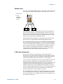
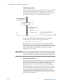
Power supply outputs may be connected
so as to float relative to earth ground.
Isolation or floating voltage ratings are
indicated on the instrument, near the
output connectors (see example below).
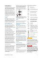
Safety Symbols and Notices
Direct current
Alternating current
Direct and alternating current
OUTPUT
3-phase alternating current
Earth (ground) terminal
240 VDC
Max
Do not float the power supply output on
the line-voltage mains. Observe all safety
markings and protection limits.
Protective earth terminal
Frame or chassis terminal
Terminal is at earth potential
Fuses
Neutral conductor on permanently installed equipment
The instrument contains an internal fuse,
which is not customer accessible.
Line conductor on permanently installed equipment.
Do Not Operate in an Explosive
Atmosphere
Off supply
Do not operate the instrument in the
presence of flammable gases or fumes.
Do Not Remove the Instrument
Cover
Only qualified, service-trained personnel
who are aware of the hazards involved
should remove instrument covers. Always
disconnect the power cable and any
external circuits before removing the
instrument cover.
Do Not Modify the Instrument
Do not install substitute parts or perform
any unauthorized modification to the
product. Return the product to an Agilent
Sales and Service Office for service and
repair to ensure that safety features are
maintained.
In Case of Damage
On supply
Standby supply - unit is not
completely disconnected from
AC mains when switch is off
In position of a bi-stable push
switch
Out position of a bi-stable
push switch
Caution, risk of electric shock
Caution, hot surface
Caution, refer to
accompanying description
CAUTION
Denotes a hazard. It calls attention to an
operating procedure, practice, or the like
that, if not correctly performed or adhered to,
could result in damage to the product or loss
of important data. Do not proceed beyond a
CAUTION notice until the indicated
conditions are fully understood and met.
Instruments that appear damaged or
defective should be made inoperative and
WARNING
secured against unintended operation
until they can be repaired by qualified
Denotes a hazard. It calls attention to an
service personnel.
operating procedure, practice, or the like
that, if not correctly performed or adhered
Cleaning
to, could result in personal injury or death.
Clean the outside of the instrument with Do not proceed beyond a WARNING notice
a soft, lint-free, slightly dampened cloth. until the indicated conditions are fully
Do not use detergent or solvents.
understood and met.
3
In this Book
Specific chapters in this manual contain the following information:
Quick Reference – Chapter 1 is a quick reference section that
helps you quickly become familiar with your DC Power Analyzer.
Installation – Chapter 2 describes how to install your DC Power
Analyzer. It discusses topics such as how to connect loads to the
output, 4-wire sensing, parallel and series connections.
Using the Source functions – Chapter 3 describes how to use the
power supply and the arbitrary waveform generator using the
front panel and SCPI commands.
Using the Measurement functions – Chapter 4 describes how to
use the front panel output meters, scope view, and data logger.
Using the System functions – Chapter 5 describes file functions
and administrative functions.
Advanced Source and Measurement Functions – Chapter 6
discusses advanced source functions and measurement functions
such as lists, digitizing measurements, and external data logging.
Specifications – Appendix A describes the mainframe
characteristics.
SCPI Commands – Appendix B summarizes the SCPI commands.
Using the Digital Port – Appendix C describes how to configure
and use the digital port on the instrument’s rear panel.
For complete details on the SCPI (Standard Commands for
Programmable Instruments) commands, refer to the N6705
Programmer’s Reference Help file included on the Agilent N6705
Product Reference CD. This CD-ROM is shipped along with your
instrument.
NOTE
4
You can contact Agilent Technologies at one of the following telephone
numbers for warranty, service, or technical support information.
In the United States: (800) 829-4444
In Europe: 31 20 547 2111
In Japan: 0120-421-345
Or use our Web link for information on contacting Agilent in your country or
specific location: www.agilent.com/find/assist
Or contact your Agilent Technologies Representative.
Model N6705 User’s Guide
Updates
Firmware and Manual Updates
This manual describes firmware revision D.01.08 and up. Go to
www.agilent.com/find/N6705firmware if you need to download this
or any later versions of the firmware. Information on firmware
differences is available on the web site.
Refer to “View Output Ratings” in chapter 2 to view the firmware
version that is currently installed in your mainframe.
Refer to “Updating the Firmware” in chapter 5 for information on
how to update your mainframe with the latest firmware. Note that
Agilent N675xA power modules must have Option LGA to support
the latest firmware versions.
Updated versions of this manual are also posted on the web. Go to
www.agilent.com/find/N6705 to get the latest version of the manual.
Agilent N6705B Differences
Model N6705 User’s Guide
•
Voltage and Current knob push-button functions. Pushing the
front panel voltage and current knobs displays a menu from
which you can: 1. Lock/Unlock the knobs. 2. Select limit
parameters or select limit tracking on Models N678xA.
•
Rear panel output ports are provided for Agilent N6753A
high current load leads. See “Agilent N6753A High Current
Connections” in chapter 2 for details.
•
Rear panel auxiliary terminals are provided for Agilent
N6781A auxiliary measurement inputs. See “Connecting the
Auxiliary Voltage Measurement Input” in chapter 2 for
details.
5
Contents
1 - Quick Reference ..................................................................................................................... 11
The Agilent N6705 DC Power Analyzer – At a Glance ............................... 12
Source Features ......................................................................................... 12
Measurement Features ............................................................................ 13
System Features ........................................................................................ 13
Power Module Features ........................................................................... 14
Agilent N678xA Power Module Features .............................................. 15
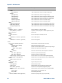
The Front Panel - At a Glance......................................................................... 16
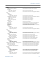
The Rear Panel – At a Glance ......................................................................... 17
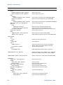
Meter View......................................................................................................... 18
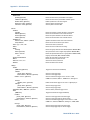
Scope View ........................................................................................................ 19
Data Logger ........................................................................................................ 20
Arb Preview ........................................................................................................ 21
Front Panel Menu Reference .......................................................................... 22
2 - Installation............................................................................................................................... 25
General Information .......................................................................................... 26
Models ......................................................................................................... 26
Options ........................................................................................................ 26
Items Supplied ........................................................................................... 26
Inspecting the Unit ........................................................................................... 27
Installing the Unit.............................................................................................. 28
Safety Considerations ............................................................................... 28
Environment................................................................................................ 28
Cleaning....................................................................................................... 28
Power Module Location ........................................................................... 28
Power Module Installation ....................................................................... 29
High Current Output Connections .......................................................... 31
Bench Installation ..................................................................................... 32
Rack Installation ........................................................................................ 32
400 Hz Operation ....................................................................................... 32
Connecting the Line Cord ................................................................................ 33
Connecting the Outputs ................................................................................... 33
Wire Size and Length ................................................................................ 34
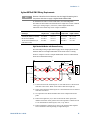
Agilent N678xA SMU Wiring Requirements ......................................... 35
Multiple Loads ........................................................................................... 37
4-Wire Sense Connections ...................................................................... 37
Parallel Connections ................................................................................. 40
Series Connections ................................................................................... 41
Additional Load Considerations .............................................................. 42
Connecting the BNC Connectors ................................................................... 44
Installing a Redundant Ground for 400 Hz Operation.......................... 44
6
Model N6705 User’s Guide
Connecting the Digital Port ............................................................................. 45
Connecting the Auxiliary Voltage Measurement Input .............................. 46
Connecting to the Interfaces .......................................................................... 47
GPIB/USB Interfaces ................................................................................ 47
LAN Interface ............................................................................................. 49
Viewing the Active LAN Status .............................................................. 51
Modifying the LAN Settings .................................................................... 51
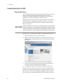
Communicating Over the LAN ........................................................................ 54
Using the Web Server ............................................................................... 54
Using Telnet ............................................................................................... 55
Using Sockets............................................................................................. 55
3 - Using the Source Functions .................................................................................................. 57
Turning the Unit On .......................................................................................... 58
View the Error Log ..................................................................................... 58
View Output Ratings ................................................................................. 59
Using the Power Supply ................................................................................... 60
Controlling the Outputs ............................................................................ 60
Additional Source Settings ...................................................................... 62
Agilent N678xA SMU Emulation Settings ............................................. 63
Configuring a Turn-On/Turn-Off Sequence .......................................... 67
Configuring Advanced Properties ........................................................... 70
Configuring Protection Functions ........................................................... 72
Configuring Advanced Protection ........................................................... 74
Using the Arbitrary Waveform Generator ..................................................... 75
Configuring Pulse Arbs ............................................................................. 76
Configuring User-Defined Arbs ............................................................... 78
Configuring Constant-Dwell Arbs ........................................................... 81
Configuring an Arb Sequence.................................................................. 84
Arbitrary Waveform Parameters ............................................................. 88
Arb Trigger Sources .................................................................................. 99
Arb Triggers .............................................................................................. 100
Importing/Exporting User-Defined and Constant-Dwell Arb Data.. 102
4 - Using the Measurement Functions ....................................................................................103
Using the Meter Functions ............................................................................ 104
Meter View ............................................................................................... 104
Meter Ranges ........................................................................................... 105
Agilent N678xA SMU Meter-Only Modes ........................................... 106
Agilent N6781A Auxiliary Voltage Measurements ............................ 108
Using the Scope Functions............................................................................ 109
Making a Measurement ......................................................................... 109
Scope View ............................................................................................... 112
Scope Properties...................................................................................... 116
Model N6705 User’s Guide
7
Scope Ranges........................................................................................... 117
Scope Marker ........................................................................................... 118
Scope Horizontal ...................................................................................... 118
Scope Preset ............................................................................................ 118
Using the Data Logger Functions ................................................................. 119
Logging Data ............................................................................................ 119
Data Logger View .................................................................................... 123
Data Logger Properties ........................................................................... 127
Data Logger Ranges ................................................................................ 128
Data Logger Trigger................................................................................. 129
Data Logger Filename ............................................................................. 131
Data Logger Marker ................................................................................ 131
Data Logger Preset .................................................................................. 132
Data Logger Sampling Modes ............................................................... 133
Scope and Data Logger Display Differences....................................... 135
5 - Using the System Functions................................................................................................137
Using the File Functions ................................................................................ 138
Save Function ........................................................................................... 138
Load Function ........................................................................................... 139
Export Function ........................................................................................ 139
Import Function ........................................................................................ 140
Screen Capture......................................................................................... 140
Show Details ............................................................................................ 141
Delete Function ........................................................................................ 141
Rename Function ..................................................................................... 142
Copy Function........................................................................................... 142
New Folder................................................................................................ 143
Reset/Recall/Power-On State .............................................................. 143
Using an External USB Memory Device .............................................. 144
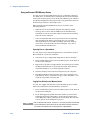
Configuring User Preferences ....................................................................... 145
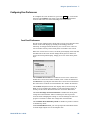
Front Panel Preferences ......................................................................... 145
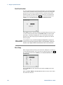
Front Panel Lockout ................................................................................ 146
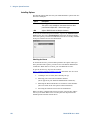
Clock Setup ............................................................................................... 146
Using the Administrative Tools .................................................................... 147
Administrator Login/Logout .................................................................. 147
Instrument Calibration ............................................................................ 147
Securing the USB, LAN, and Web Server ........................................... 148
Restoring the Non-volatile Factory Settings ....................................... 148
Disk Management ................................................................................... 149
Updating the Firmware ........................................................................... 149
Installing Options..................................................................................... 150
Changing the Password.......................................................................... 151
8
Model N6705 User’s Guide
6 - Advanced Source and Measurement Functions...............................................................153
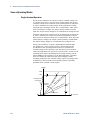
Source Operating Modes ............................................................................... 154
Single Quadrant Operation ..................................................................... 154
Autoranging .............................................................................................. 155
Downprogramming .................................................................................. 155
CC Mode Delay ........................................................................................ 155
Power Limit Operation ............................................................................ 156
Output Grouping ...................................................................................... 157
Agilent N678xA SMU Multi-Quadrant Operation ............................... 158
Output Bandwidth ................................................................................... 161
Advanced Measurements .............................................................................. 162
Digitizing Measurements ....................................................................... 162
External Data Logging............................................................................. 168
Dynamic Current Correction Control .................................................... 172
Measurement System Bandwidth ........................................................ 173
Averaged Measurements ....................................................................... 174
Agilent N6781A and N6782A Current Histogram Measurements .. 175
Measurement Data Formats .................................................................. 178
Appendix A - Specifications .....................................................................................................179
Agilent N6705A, N6705B DC Power Analyzer Mainframe....................... 180
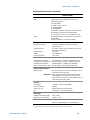
Supplemental Characteristics................................................................ 180
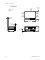
Outline Diagram ....................................................................................... 182
Appendix B - SCPI Commands and Instrument Settings ......................................................183
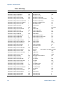
SCPI Command Summary .............................................................................. 184
Common Commands ............................................................................... 193
Interface Settings .................................................................................... 193
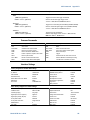
Power-On Settings .................................................................................. 194
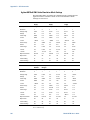
Agilent N678xA SMU Initial Emulation Mode Settings .................... 196
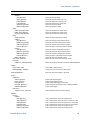
Appendix C - Using the Digital Port.........................................................................................197
Configuring the Digital Port ........................................................................... 198
Bi-directional Digital I/O ........................................................................ 198
Digital Input .............................................................................................. 200
Fault Output .............................................................................................. 200
Inhibit Input .............................................................................................. 201
Fault/Inhibit Operating Mode................................................................ 202
Fault/Inhibit System Protection............................................................ 203
Trigger Input ............................................................................................. 203
Trigger Output .......................................................................................... 204
Output Couple Controls .......................................................................... 205
Model N6705 User’s Guide
9
Agilent N6705 DC Power Analyzer
User’s Guide
1
Quick Reference
The Agilent N6705 DC Power Analyzer – At a Glance ............................... 12
The Front Panel - At a Glance......................................................................... 16
The Rear Panel – At a Glance ......................................................................... 17
Meter View......................................................................................................... 18
Scope View ........................................................................................................ 19
Data Logger ........................................................................................................ 20
Arb Preview ........................................................................................................ 21
Front Panel Menu Reference .......................................................................... 22
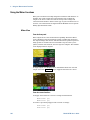
This chapter concisely describes the operation of the Agilent N6705
DC Power Analyzer.
This chapter does not describe every operating feature in detail. It is
simply a quick reference guide to quickly become familiar with the
operating features of the Agilent N6705 DC Power Analyzer.
NOTE
Unless otherwise noted, the Agilent N6705 DC Power Analyzer will also be
referred to as “DC Power Analyzer” throughout this manual.
11
1
Quick Reference
The Agilent N6705 DC Power Analyzer – At a Glance
The Agilent N6705 DC Power Analyzer is a multi-functional power
system that combines the functions of a multiple-output DC voltage
source with the waveform/data capturing capability of an
oscilloscope and data logger.
As a multiple-output DC source, the Agilent N6705 provides up to
four configurable outputs. Available power modules have power
levels of 20 W through 500 W, have various voltage and current
combinations, and provide a variety of performance features as
described under “Power Module Capabilities”. Each output also has
arbitrary (Arb) waveform generation capability, which lets you
program predefined voltage and current waveforms – or define your
own waveforms. Agilent N678xA Source/Measure Units (SMU) have a
multiple-quadrant power mesh with separate voltage and current
priority source modes.
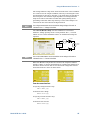
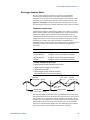
As a measurement system, the Agilent N6705 displays the average
output voltage and current in Meter View. Waveforms are displayed
in Scope View, which you can adjust using vertical and horizontal
controls. The Data Logger View measures and charts average and
peak voltage and current measurements over an extended period.
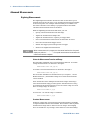
Source Features
Color-coded display and
output controls
Correspondence between color-coded information on the display and front
panel connectors and keys.
Programmable voltage
and current
Full programming capability is provided for the entire range of output
voltage and current for all power modules.
Low output noise
Available on Agilent N676xA and N675xA power modules. Output noise is
<4.5 mV peak-to-peak, which is comparable to linear supplies.
Fast up/down
programming
Available on Agilent N675xA, N676xA, and N678xA SMU power modules.
≤1.5 millisecond response time from 10% to 90% of the output rating.
Fast transient response
Available on Agilent N675xA, N676xA, and N678xA SMU power modules.
Transient response is less than 100 μs.
Output autoranging
capability
Available on Agilent N676xA and N675xA power modules.
Autoranging supplies the maximum rated power over a continuous range of
voltage and current settings.
Output On/Off sequencing A turn-on/turn-off delay capability for each output allows output on/off
sequencing.
Front panel binding posts + and – output and + and – sense terminals are provided for each output.
Sense terminals provide 4-wire voltage measurements.
12
Output protection
Outputs have over-voltage, over-current, and over-temperature protection.
Emergency shut-off
An emergency stop button to quickly shut down all outputs.
Multiple-Quadrant
operation
Available on Agilent N678xA SMU and N6783A power modules.
2- and 4-quadrant operation provides source and sink output capability.
Model N6705 User’s Guide
Quick Reference
1
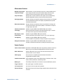
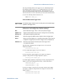
Measurement Features
Multiple-output/Singleoutput meter display
Switch between a 4-output summary view and a 1-output detailed view of
power supply information. All power modules display real-time output
voltage and current measurements as well as status information.
Scope-like display
Voltage and/or current waveforms of all outputs can be simultaneously
displayed. Adjustable markers provide calculated measurements.
Data logging display
Average, minimum, and maximum voltage and current values can be logged
over an extended time period to the display. Adjustable markers provide
calculated measurements.
Measurement functions
Average, minimum, and maximum values are provided for all voltage and
current measurements. Output power (Watts) is calculated for all outputs
in single-output meter view.
Seamless measurement
autoranging
Available on Agilent N6781A and N6782A SMU power modules.
Output measurements seamlessly autorange between ranges – however,
the 10 μA current range must be selected manually.
Microampere current
measurements
Available on Agilent N678xA SMU power modules.
Current measurement can be made as low as 1 μA in the 10 μA range.
Fast digitizing
Available on Agilent N678xA SMU power modules.
5.12 μs/sample for one parameter; 10.24 μs/sample for two parameters.
Histogram measurement Available on Agilent N6781A and N6782A SMU power modules.
Provides a statistical measurement for profiling the measured current.
System Features
Choice of three interfaces LAN, USB, and GPIB (IEEE-488) remote programming interfaces are built in
Menus let you set up GPIB and LAN parameters from the front panel.
Built-in Web server
A built-in Web server lets you control the instrument directly from an
internet browser on your computer.
SCPI language
The instrument is compatible with the Standard Commands for
Programmable Instruments (SCPI).
Savable instrument data A file management system saves display bitmaps, instrument states, scope
results, arbitrary waveforms, and data log results.
Memory port
Front USB port allows files to be saved to an external USB memory device.
Trigger connectors
Rear panel trigger in/out BNC connectors
Low acoustic noise
Low acoustic noise for quiet bench operation.
Universal AC input
Mainframes have universal input voltage capability with active power factor
correction.
Model N6705 User’s Guide
13
1
Quick Reference
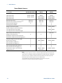
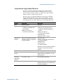
Power Module Features
Feature
DC Power
High-Performance
Precision
N673xB, N674xB, N677xA
N675xA
N676xA
50 W output rating
N6731B – N6736B
N6751A
N6761A
100 W output rating
N6741B – N6746B
N6752A
N6762A
300 W output rating
N6773A – N6777A
N6753A, N6754A
N6763A, N6764A
N6755A, N6756A
N6765A, N6766A
Option 761
Option 761
Option 761
Option 760
Option 760
Option 760
●
●
●
●
●
(● = available)
500 W output rating
Output disconnect relays
Output disconnect/polarity reversal relays
NOTE 1
Arbitrary waveform generation
Autoranging output capability
Voltage or current turn-on priority
N6761A, N6762A
Precision voltage and current measurements
●
Low voltage and current output ranges
N6761A, N6762A
Low voltage and current measurement ranges
200 microampere measurement range
●
Option 2UA
NOTE 2
Voltage or current scope traces
●
●
●
Simultaneous voltage and current scope traces
Simultaneous voltage and current data logging
Interleaved voltage and current data logging
●
NOTE 3
Dynamic current correction
SCPI command list capability NOTE 4
SCPI command array readback
NOTE 4
SCPI command programmable sample rate
NOTE 4
SCPI command external data logging NOTE 4
Double-wide (occupies 2 channel locations)
Large gate array
NOTE 5
●
NOTE 3
●
●
●
N6751A, N6752A
N6761A, N6762A
●
●
●
●
●
●
●
●
●
●
●
●
N6753A – N6756A
N6763A – N6766A
Option LGA
Notes:
1
Output current is limited to 10A max. on Models N6742B and N6773A with Option 760.
Option 760 is not available on Models N6741B, N6751A, N6752A, N6761A, and N6762A.
2
Option 2UA is only available on Models N6761A and N6762A. It includes Option 761.
3
Option 055 deletes the Data Logger function on Model N6705.
4
Only available when using the remote interfaces; not from the front panel.
5
Option LGA is required on Models N6751A and N6752A.
14
Model N6705 User’s Guide
Quick Reference
1
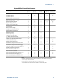
Agilent N678xA Power Module Features
Feature
Source/Measure Units (SMU)
Application-Specific
(● = available)
N6781A
N6782A
N6784A
N6783A-BAT
N6783A-MFG
Output rating
20 W
20 W
20 W
24 W
18 W
●
●
●
●
2-quadrant operation
4-quadrant operation
●
Auxiliary voltage measurement input
●
Output disconnect relays
●
●
●
Option 761
Option 761
Arbitrary waveform
generation NOTE 1
●
●
●
●
●
Negative voltage protection
●
●
●
●
●
Voltage or current priority mode
●
●
●
CC load/CV load
●
●
●
Battery emulator/charger
●
●
●
Voltage/current measurement only
●
●
●
Programmable output resistance
●
600 mV output range
●
●
●
300 mA output range
●
●
●
●
●
●
●
●
100 mA, 10 mA output ranges
●
1 V, 100 mV measurement ranges
●
●
●
100 mA, 1 mA, 10 μA measurement ranges
●
●
●
150 mA measurement range
Voltage or current scope traces
Simultaneous voltage and current scope traces
Simultaneous voltage and current data logging
NOTE 2
●
●
●
●
●
●
●
●
●
Interleaved voltage and current data logging NOTE 2
Seamless measurement autoranging
●
●
SCPI command list capability
●
●
●
●
●
NOTE 1, 3
SCPI command array readback
●
●
●
●
●
SCPI command programmable sample rate NOTE 3
●
●
●
●
●
SCPI command external data logging
●
●
●
●
●
●
●
NOTE 3
NOTE 3
SCPI command histogram measurements
NOTE 3
Notes:
1
Arbitrary waveform generation and List capability are not available on the negative
current output on Model N6783A.
2
Option 055 deletes the Data Logger function on Model N6705.
3
Only available when using the remote interfaces; not the front panel.
Model N6705 User’s Guide
15
1
Quick Reference
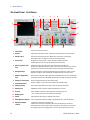
The Front Panel - At a Glance
3
4
5
6
7
9
8
10
2
11
12
1
16
16
15
14
13
1
Line switch
Turns the instrument On or Off.
2
Display
Displays all instrument functions - information changes based on selected function.
3
Measure keys
Selects the measurement function - Meter View, Scope View, or Data Logger.
Run/Stop key starts or stops the scope or data log measurement.
4
Source keys
Programs the source function – Source Settings or Arbitrary waveform.
Arb Run/Stop key starts or stops the arbitrary waveform function.
5
Menu, Properties, File
keys
Menu key accesses all mode controls via a hierarchical command menu.
Properties key displays information specific to the active view (this is a menu shortcut).
File key lets you save the current display, instrument settings, and measurements.
6
Navigation keys
Navigate through the control dialog windows; press the Enter key to select a control.
Back key cancels the values entered into the dialog and backs out of the control.
7
Numeric/Alpha Entry
keys
Enters numeric and alpha values. Alpha keys automatically become active on fields that
allow alpha character entry. Repeatedly pressing the key scrolls thorough the selections.
8
Voltage/Current knobs
Sets the voltage and current of the selected output.
9
Select Output keys
Selects an output to control. The lit key indicates the selected output.
10
Emergency Stop
Turns off all outputs without any delays; aborts any arbitrary waveforms.
11
Memory port
USB Memory device connector. Option AKY deletes the connector.
12
On keys
Turns individual outputs On or Off; outputs are on when the key is lit.
13
Binding posts
+ and – output and sense banana terminals for all outputs.
14
4 Wire
Indicates that 4 Wire sensing is enabled on the output.
15
All Outputs On/Off keys
Turns all outputs On and Off according to the specified turn-on and turn-off delays.
16
Waveform Display
controls
Controls the scope and data logging views.
Vertical knobs control the vertical size and position. Press Offset to set marker 1.
Horizontal knobs control the horizontal size and position. Press Offset to set marker 2.
The Trigger knob moves the trigger level up or down. Press this knob to autoscale.
Model N6705 User’s Guide
Quick Reference
1
The Rear Panel – At a Glance
1
2
8
9
7
3
4
5
6
1
Cover screw
Facilitates top and bottom cover removal for power module installation.
2
Digital Port connector
Connects to the 8-pin digital port. Port functions are user-configurable. Refer to
appendix C for details.
3
USB interface connector
Connects to USB interface. May be disabled from front panel menu. Option AKY deletes
the connector.
4
LAN interface connector
Connects to 10/100 Base-T interface. Left LED indicates activity. Right LED indicates
link integrity. May be disabled from front panel menu.
5
AC input connector
3-pin IEC 320 AC input connector. Power cord requires ground conductor.
6
GPIB interface connector
Connects to GPIB interface. May be disabled from front panel menu.
7
Trigger connectors
BNC connectors for trigger in and trigger out signals. Refer to Appendix A for signal
descriptions.
8
Aux Voltage Measurement Auxiliary voltage measurement connector. Only available on Agilent N6705B
mainframes for use with Agilent N6781A power modules.
connector
9
Wiring access ports
WARNING
Model N6705 User’s Guide
Access for sense and output wire connections. Only available on Agilent N6705B
mainframes. Used for output connections on power modules rated > 20 A.
Also used for Agilent N678xA SMU power modules when extremely precise
measurements or output guarding is required.
SHOCK HAZARD The power cord provides a chassis ground through a third
conductor. Be certain that your power outlet is of the three-conductor type
with the correct pin connected to earth ground.
17
1
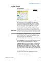
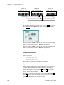
Quick Reference
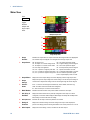
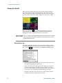
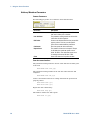
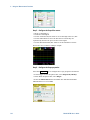
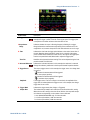
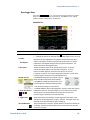
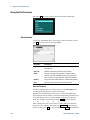
Meter View
Press
Meter View
This key
toggles
between
multiple and
single output
views
1
3
2
4
5
Multiple Output View
6
7
8
9
10
Single Output View
1
Output
Identifier
Identifies the output. When an output is selected, the background becomes highlighted.
The selected output is displayed in an enlarged format in single output view.
2
Output Status
Off: the output is off
CV: the output is in constant voltage mode
CC: the output is in constant current mode
Unr: the output is unregulated
CP+, CP–: a positive or negative power limit
CL+, CL–: a positive or negative current limit
VL+, VL–: a positive or negative voltage limit
3
Output Meters
Displays the actual output voltage and current. Displays power in single output view.
4
Output
Settings
Displays the present output voltage and current settings. Turn the front panel voltage or
current knob to adjust these settings. Can also be changed using the numeric keypad.
5
Interface
Status
Error – an error has occurred (press the Menu key, select Utilities, then Error Log)
LAN – the LAN is connected and has been configured
IO – there is activity on one of the remote interfaces
6
Model Number
Identifies the model number of the power module connected to this output.
7
Arb, Delay, &
Slew Rate
Displays the Arb waveform that is presently configured for this output. If no Arb is
configured, no waveform will be displayed. Also displays the Output On and Output Off
delay settings as well as the slew rate setting.
8
Polarity Reverse
Indicates that the output and sense polarities are reversed.
9
Ratings &
Protection
Displays the maximum voltage and current ratings of the output. Also displays the
present over-voltage protection setting and whether over-current protection is on or off.
Other Outputs
Displays the actual voltage, current, and status of the other outputs.
10
18
OV: over-voltage protection tripped
OV–: negative voltage protection tripped
OC: over-current protection tripped
OT: over-temperature protection tripped
PF: a power-fail condition occurred
Inh: an external inhibit signal is received
Osc: the oscillation protection tripped
Prot: a coupled output protect occurred
Model N6705 User’s Guide
Quick Reference
1
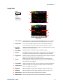
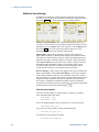
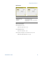
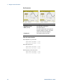
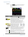
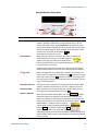
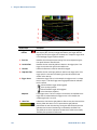
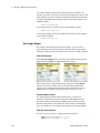
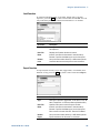
Scope View
Press
Scope View
This key
toggles
between
standard and
marker views.
1
5
2
6
7
3
8
4
9
Standard View
10
11
12
13
Marker View
1
Trace Controls
Identifies the voltage or current trace that will be displayed. Dashes (----) indicate that
the specified trace is turned off. Select the trace and press Enter to turn it on or off.
2
Output Traces
V1, V2, V3, and V4 indicate voltage traces. I1, I2, I3, and I4 indicate current traces.
P1 and P2 indicate power traces. Press Trigger Level knob to autoscale all traces.
3
Horizontal
Time-base
Identifies the horizontal time-base settings. These can be adjusted using the front panel
Horizontal Time/Div and Offset knobs.
4
Scope Status
Indicates whether the scope is idle, running, or waiting for a trigger.
5
Data Bar
The highlighted area shows how much of the entire measurement is actually shown on
the display. Use the Horizontal Time/Div knob and Offset knob to adjust the display
6
Trigger Level
Identifies the trigger level through which the waveform must pass before the scope will
trigger. This can be adjusted using the Trigger Level knob.
7
Ground
Identifies the ground reference level for the trace. This can be adjusted using the
Vertical Offset knob. The initial vertical offset of each trace is set to a different level to
prevent the traces from overlapping.
8
Trigger Mode
Identifies the trigger mode setting. This can be selected by pressing the Properties key.
9
Trigger Source
Identifies the trigger source and trigger level. Voltage 1 indicates a voltage level on
output 1 is the trigger source (see #6).
10
M1 Marker
Measurement Marker 1 enabled. Adjust using Marker 1 knob. Press knob to reset.
11
M2 Marker
Measurement Marker 2 enabled. Adjust using Marker 2 knob. Press knob to reset.
12
Intersect Point
Shows where the measurement markers intersect the waveform.
13
Measurements
Shows the calculations of the waveform data between Marker 1 and Marker 2.
Model N6705 User’s Guide
19
1
Quick Reference
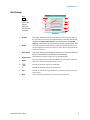
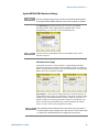
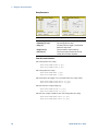
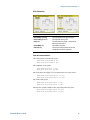
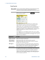
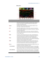
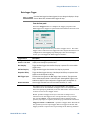
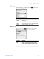
Data Logger
NOTE
Press
Data Logger
This key
toggles
between
standard and
marker views
Option 055 deletes the Data Logger function on Model N6705.
1
5
2
6
3
4
7
Standard View
8
9
10
11
Marker View
20
1
Trace Controls
Identifies the voltage or current trace that will be displayed. Dashes (----) indicate that
the specified trace is turned off. Select the trace and press Enter to turn it on or off.
2
Output Traces
Voltage, current, or power traces. Voltage traces V1,V2, V3 and V4 shown.
Press Trigger Level knob to autoscale all traces.
3
Status
Indicates whether the Data Logger is logging data, done logging, or is empty.
4
Filename
Indicate the file to which the data is being logged.
5
Data Bar &
Time Elapsed
Displays the progress of the data logger. The yellow bar indicates the visible data.
Numbers to the right indicate time elapsed/total duration.
6
Time base
Information
Displays the time remaining before the trigger point; the time at the center line of the
grid in relation to trigger point; and the time elapsed since the trigger.
7
Trigger
Identifies the trigger source and trigger offset. The trigger offset is specified in % of the
total duration, but shown in seconds on the display.
8
M1 Marker
Measurement Marker 1 enabled. Adjust using Marker 1 knob. Press knob to reset.
9
M2 Marker
Measurement Marker 2 enabled. Adjust using Marker 2 knob. Press knob to reset.
10
Intersect Point
Shows where the measurement markers intersect the waveform.
11
Measurements
Shows the calculations of the waveform data between Marker 1 and Marker 2.
Model N6705 User’s Guide
Quick Reference
1
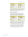
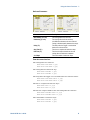
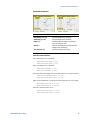
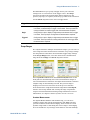
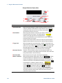
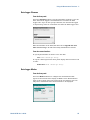
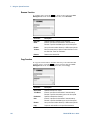
Arb Preview
Press
Arb
This dialog
displays the
arbitrary
waveforms
that have been
configured.
1
2
5
3
6
7
4
8
9
Arb Preview
1
DC Value
This column indicates the present output voltage or current setting that appears at
the output before the Arb is run. The output will return to this value after the Arb
complete if the Return to DC value box has been checked. If the Last Arb
Value box is checked, the output will remain at the last programmed Arb value.
2
Output
This column identifies the output channel on which the associated waveform will run.
Use the navigation keys to select an output if you wish to select an Arb or edit the Arb
on that output channel.
3
Wave shapes
This column illustrates the waveshapes that will run on each output when the
arb(s) are started. Note that all Arbs will run simultaneously.
4
Trigger Source
This dropdown list selects the trigger source for all configured Arbs.
5
Repeat
This column indicates how many times the Arb will repeat if it has been configured to
repeat. If the column is blank, the Arb will only run once.
Indicates that the Arb on output 2 runs continuously.
6
7
3
Indicates that the Arb on output 3 repeats three times.
8
Time
Indicates the time that the longest Arb will run. In this example, all Arbs run the same
amount of time.
9
Close
Closes the Arb Preview and returns to the previous measurement view.
Model N6705 User’s Guide
21
1
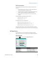
Quick Reference
Front Panel Menu Reference
Menu Heading
Description
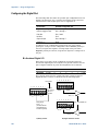
Source Settings ►
Voltage and Current Settings…
Configures the voltage and current settings, ranges, and emulation modes.
Protection…
Configures the over-voltage and over-current protection. Enables output coupling so ALL
outputs are disabled when a fault occurs. Also clears output protection.
Advanced Protection…
Enables/disables the output inhibit function.
Output On/Off Delays…
Configures output on/off delays.
Output On/Off Coupling…
Couples specific outputs for the output on/off and delay function.
Output Grouping…
Groups identical outputs for output paralleling function.
Advanced…
Configures advanced functions including voltage slew rate, sensing, and power limit.
Ratings…
Displays power module ratings, serial number, firmware, and option information.
Arb ►
Arb Preview
Displays the present status of the arbitrary waveforms that have been configured.
Arb Selection…
Selects arbitrary waveforms for each output. Arb Properties configures the selected Arb.
Meter ►
All Outputs Meter View
Displays the meter view of all outputs.
Single Output Meter View
Displays the meter view of the selected output.
Meter Properties…
Configures the meter view voltage and current measurement ranges.
Scope ►
Standard View
Displays the standard scope view including vertical, horizontal, and trigger settings.
Marker View
Displays the measurement markers and measurement calculations area.
Scope Properties…
Configures the scope traces and voltage and current measurement ranges for individual
outputs. Also configures the trigger source, mode, and horizontal offset.
Marker Properties…
Configures the measurements that appear on the bottom of the display in Marker view.
Horizontal Properties…
Configures the horizontal offset reference and sample points.
Datalogger ►
Standard View
Displays the data log strip chart view including vertical, horizontal, and progress settings.
Marker View
Displays the measurement markers and measurement calculations area.
Datalogger Properties…
Configures the data log traces and voltage and current measurement ranges for individual
outputs. Also configures the data log duration, sample period, and Min/Max values.
File Name Selection…
Specifies the filename for the next data logger acquisition.
Marker Properties…
Configures the measurements that appear on the bottom of the display in Marker view.
File ►
22
Save…
Saves an instrument state or a scope measurement.
Load…
Loads an instrument state, scope data, or logged data.
Export…
Exports scope data, logged data, or a user-defined arbitrary waveform
Import…
Imports s user-defined arbitrary waveform.
Screen Capture…
Captures the screen that was active when the File key was pressed.
File Management…
Accesses additional file functions: New Folder, Delete, Rename, Copy, File Details.
Reset/Recall/Power-On State…
Resets the instrument to factory defaults; Saves/recalls instrument states; and specifies
the power-on turn on state.
Model N6705 User’s Guide
Quick Reference
1
Front Panel Menu Reference (continued)
Menu Heading
Description
Utilities ►
Error Log…
Lists all error messages.
I/O Configuration ►
Active LAN Status…
Displays the LAN status and active settings.
LAN Settings…
Configures the LAN interface.
GPIB/USB…
Configures the GPIB and USB interface.
User Preferences ►
Front Panel Preferences…
Configures screen saver, front panel key functions, and initial meter view.
Front panel Lockout…
Password-protects the front panel keys.
Clock Setup…
Sets up the internal clock.
Administrative Tools ►
Administrator Login/Logout…
Accesses the password-protected administrative functions.
Calibration ►
Accesses the calibration functions.
I/O Access…
Enables/disables the LAN, Web server, and USB.
Nonvolatile RAM Reset…
Resets all non-volatile memory settings to the factory defaults.
Disk Management…
Checks the internal drive.
Firmware Update…
Installs updated firmware from the front panel Memory port.
Install Options…
Installs additional firmware options.
Change Admin Password…
Digital I/O…
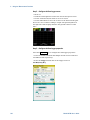
Changes the administrator password.
Configures the digital port. All seven pins of the digital port can be individually configured.
Help ►
Overview…
A brief overview.
Quick Start ►
How to quickly get started.
Using the Agilent N6705 ►
How to use the Agilent N6705.
Using the Utilities ►
How to use the utilities.
Front Panel Controls ►
How to use the front panel controls.
Front Panel Navigation…
How to navigate the front panel display.
Module Capabilities and Ratings
How to obtain module capabilities/ratings.
About
Model N6705 User’s Guide
Identifies the mainframe and the installed modules
23
Agilent N6705 DC Power Analyzer
User’s Guide
2
Installation
General Information .......................................................................................... 26
Inspecting the Unit ........................................................................................... 27
Installing the Unit.............................................................................................. 28
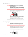
Connecting the Line Cord ................................................................................ 33
Connecting the Outputs ................................................................................... 33
Connecting the BNC Connectors ................................................................... 44
Connecting the Digital Port ............................................................................. 45
Connecting the Auxiliary Voltage Measurement Input .............................. 46
Connecting to the Interfaces .......................................................................... 47
Communicating Over the LAN ........................................................................ 54
This chapter describes how to install your DC Power Analyzer. It
discusses rack mounting and line cord connections.
This chapter also discusses how to connect your load to the output
terminals, wiring considerations as well as series/parallel
connections.
Finally, detailed information is provided about connecting to the
GPIB, USB, and LAN interfaces.
25
2
Installation
General Information
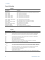
Models
Agilent Model
Description
N6705A, N6705B
600 W DC Power Analyzer mainframe - without power modules
N6715A, N6715B
Build-to-order DC Power Analyzer system - mainframe with installed power modules
N6731B / N6741B
50 W / 100 W 5 V DC Power Module
N6732B / N6742B
50 W / 100 W 8 V DC Power Module
N6733B / N6743B / N6773A
50 W / 100 W / 300 W 20 V DC Power Module
N6734B / N6744B / N6774A
50 W / 100 W / 300 W 35 V DC Power Module
N6735B / N6745B / N6775A
50 W / 100 W / 300 W 60 V DC Power Module
N6736B / N6746B / N6776A, N6777A
50 W / 100 W / 300 W 100 V DC Power Module
N6751A / N6752A
50 W / 100 W High-Performance Autoranging DC Power Module
N6753A, N6754A / N6755A , N6756A
300 W / 500 W High-Performance Autoranging DC Power Module
N6761A / N6762A
50 W / 100 W Precision DC Power Module
N6763A, N6764A / N6765A, N6766A
300 W / 500 W Precision DC Power Module
N6781A, N6782A, N6784A
20 W Source/Measure Unit (SMU)
N6783A-MFG / N6783A-BAT
18 W / 24 W Application-Specific DC Power Module
Options
Mainframe Options
Description
ABA
English Manual Set. Contains User’s Guide and Service Guide. Also available as p/n N6705-90000.
ABJ
Japanese Manual Set. Contains User’s Guide and Service Guide. Also available as p/n N6705-90403.
AB1
Korean Manual Set. Contains User’s Guide and Service Guide. Also available as p/n N6705-90406.
AB2
Chinese Manual Set. Contains User’s Guide and Service Guide. Also available as p/n N6705-90408.
AKY
Deletes the front and rear panel USB connector.
055
Deletes the Data Logger function.
056
Agilent 14585A Control and Analysis Software.
908
Rack Mount Kit. For mounting in a 19-inch EIA rack cabinet. Also available as p/n 5063-9215.
909
Rack Mount Kit with handles. Also available as p/n 5063-9222.
Power Module Options
760 NOTE 1
Output disconnect/polarity reversal. Disconnects the + and – output and sense terminals. Switches the
+ and – output and sense polarities. Not available on N6741B, N6751A, N6752A, N676xA, or N678xA.SMU.
761 NOTE 1
Output disconnect. Disconnects + and – output and sense terminals. Available for all power modules.
LGA
Large gate array. Required on Models N6751A, N6752A for use in the DC Power Analyzer.
UK6
Commercial calibration with test results data
1A7
ISO 17025 calibration certificate
2UA
200 microampere measurement range with output disconnect relays. Only on Models N6761A, N6762A.
1
26
A small AC network is always present across the output terminals.
Model N6705 User’s Guide
Installation
2
Items Supplied
Mainframe Items
Description
Part Number
Power Cord
A power cord suitable for your location.
Call Agilent Sales & Support Office
Digital Connector plug
8-pin connector for connecting signal lines to the digital port.
Agilent 1253-6408
Phoenix Contact MC 1,5/8-ST-3,5
AUX Measurement
Connector plug (2)
8-pin connector plugs for connecting the auxiliary
measurement inputs. Only used with Agilent Model N6781A.
Agilent 1253-6408
Phoenix Contact MC 1,5/8-ST-3,5
Spare grommets
Two spare grommets for rear panel sense and load wiring.
Agilent 0400-1009
Product Reference CD-ROM
Includes drivers and documentation.
Agilent 14585-13601
Automation-Ready CD-ROM
Contains Agilent IO Libraries Suite.
Agilent E2094R
Quick Start Tutorial
A tutorial to help you quickly get started.
Agilent N6705-90005
T-10 Torx tool
Torx tool for installing or removing power modules.
Agilent 8710-2416
8 A Output Connector plug
One 8 A, 8-pin connector plug for connecting power and sense
leads. Only used in N678xA SMU.
Agilent 1253-6408
Phoenix Contact MC 1,5/8-ST-3,5
12 A Output Connector plug
One 12 A, 4-pin connector plug for connecting power and
sense leads. Used in all except N6731B, N6741B, N6753AN6756A, N6763A-N6766A, N6773A, N678xA SMU.
Agilent 1253-5826
Phoenix Contact MSTB 2,5/4-STF
20 A Output Connector plug
One 20 A, 4-pin connector plug for connecting power and
sense leads. Only used in N6731B, N6741B, N6754A, N6756A,
N6764A, N6766A, N6773A.
Agilent 1253-6211
Phoenix Contact PC 4/4-ST-7,62
50 A Output Connector plug
One 50 A, 2-pin connector plug for connecting power leads.
Only used in N6753A, N6755A, N6763A, N6765A.
Agilent 1253-7187
Molex 39422-0002
AUX Measurement
connector plug
A 2-pin connector plug for connecting the auxiliary
measurement inputs. Only used in N6781A.
Agilent 1253-8485
Phoenix Contact FMC 1,5/2-ST-3,5
Small Sense Jumpers
Two small jumpers for local sensing at the output connector.
Used in all except N6731B, N6741B, N6753A-N6756A,
N6763A-N6766A, N6773A, N678xA SMU.
Agilent 8120-8821
Phoenix Contact EPB 2-5(1733169)
Large Sense Jumpers
Two large jumpers for local sensing at the output connector.
Only used in N6731B, N6741B, N6754A, N6756A, N6764A,
N6766A, N6773A.
Agilent 0360-2935
Phoenix Contact 3118151
Sense Connector
A 4-pin connector for connecting sense leads. Wires (p/n
5185-8847) are used for local sensing. Only used in N6753A,
N6755A, N6763A, N6765A.
Agilent 1253-5830
Phoenix Contact MC 1,5/4-ST-3,5
Module Cal. Certificate
A certificate of calibration referenced to the serial number.
N/A
Power Module Items
Inspecting the Unit
When you receive your DC Power Analyzer, inspect it for obvious
damage that may have occurred during shipment. If there is damage,
notify the shipping carrier and nearest Agilent Sales and Support
Office immediately. Refer to www.agilent.com/find/assist.
Until you have checked out the DC Power Analyzer, save the shipping
carton and packing materials in case the unit has to be returned.
Check the list under “Items Supplied” and verify that you have
received these items with your instrument. If anything is missing,
please contact your nearest Agilent Sales and Support Office.
Model N6705 User’s Guide
27
2
Installation
Installing the Unit
Safety Considerations
This DC Power Analyzer is a Safety Class 1 instrument, which means
it has a protective earth terminal. That terminal must be connected to
earth ground through a power source equipped with a ground
receptacle.
Refer to the Safety Summary page at the beginning of this guide for
general safety information. Before installation or operation, check
the DC Power Analyzer and review this guide for safety warnings and
instructions. Safety warnings for specific procedures are located at
appropriate places throughout this Guide.
Environment
WARNING
Do not operate the instrument in the presence of flammable gasses or fumes
The environmental conditions of the instrument are documented in
Appendix A. Basically, the instrument should only be operated
indoors in a controlled environment.
The dimensions of your instrument as well as an outline diagram are
given in Appendix A. Fans cool the DC Power Analyzer by drawing
air through the side and exhausting it out the opposite side and back.
The instrument must be installed in a location that allows sufficient
space at the sides and back of the unit for adequate air circulation.
Cleaning
WARNING
SHOCK HAZARD To prevent electric shock, unplug the unit before cleaning.
Use a dry cloth or one slightly dampened with water to clean the
external case parts. Do not use detergent or chemical solvents. Do
not attempt to clean internally.
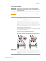
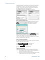
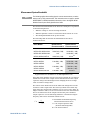
Power Module Location
The location of the power modules inside the mainframe determines
their front panel output assignments. To view the module/output
assignments, turn the unit on, press the Settings key, then press
Properties. The power modules are listed under each output channel.
Outputs that are not connected to a power module will not be
displayed in the Meter view.
28
Model N6705 User’s Guide
Installation
2
Power Module Installation
NOTE
CAUTION
The information in this section applies if you have purchased an N6705
mainframe without the power modules installed, or if you are adding a power
module to the mainframe.
Turn the mainframe off and disconnect the power cord before installing or
removing power modules. Observe all standard electrostatic discharge
precautions before handling electronic components.
Tools required: T10 Torx driver;
Small flat-blade screwdriver
5.5 mm hex wrench
Firmware Note: Newer power modules can only be installed in
N6705 mainframes with the latest firmware. Refer to the “Updates”
section in the front of this manual for more information. If your
mainframe has the latest firmware version, install the power module.
If not, download and install the latest version firmware from the web.
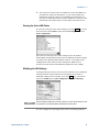
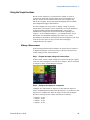
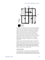
Step 1. Remove the top and bottom covers.
Loosen the thumb-screws to remove the covers. Turn the unit upsidedown to remove the bottom cover.
Step 2. Place the power modules in the mainframe
Align the power module over the pins and gently push it down onto
the connector. Install the screws at each end of the power module.
NOTE
Model N6705 User’s Guide
2
1
2
1
3
4
3
4
If you are installing a double-wide power module, you must first remove the
center deflector. Use a T10 Torx to remove the top deflector; use a 5.5 mm hex
to remove the bottom deflector. Install the deflector in the storage location on
the opposite end of the module. Connect the power module to output 1 or
output 3 only.
29
2
Installation
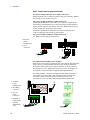
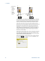
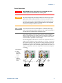
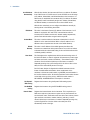
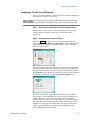
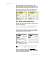
Step 3. Connect the front panel wire harness.
For power modules that use 12 A output connectors –
Simply push the 12 A connector plug into the power module. Tighten
the locking screws on the connector.
For power modules with 20 A output connectors –
On N6705B mainframes, remove the 12 A connector plug from the
wire harness and install the 20 A connector plug provided with the
power module. Observe the output color code. Tighten all connector
screws. Install the connector in the module.
On N6705A mainframes, install the wire harness with the 20 A
connector plug directly into the power module.
For power modules with 50 A output connectors –
see “High Current Output Connections”.
1. To front
panel
binding post.
2. 20 A
connector
2
1
+s +
-s
+
–
+S
–S
1
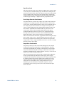
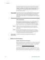
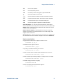
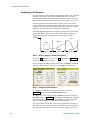
For Agilent N678xA SMU power modules –
Remove the 12A connector plug from the wire harness and install the
8-pin connector plug provided with the power module. Install the
front panel cable wires in the output connector as shown. Observe
the output color code. Tighten all connector screws. An adapter “A”
is required to install modules in Agilent N6705A mainframes.
For model N6781A, install the auxiliary measurement (Aux Meas)
cable. Remove the Aux Meas cable from its storage location and
insert the connector into the power module. The color code
corresponds to the rear panel Aux Voltage Measurement label.
1. To front
panel
binding post.
Aux Meas –
–
+
2. Aux Meas
connector
2
3. To rear
panel
connector
A. Adapter A
required for
N6705A
mainframes
only
30
3
Aux Meas +
– –
G
+ +
+S G –S
+
–
+S
–S
1
Model N6705 User’s Guide
Installation
2
Step 4. Finish the Installation.
Place any unused cable harnesses in the clip ring located between the
power modules and the front panel. Install the top and bottom
covers. Push the covers into place and tighten the thumbscrews.
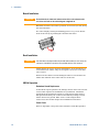
High Current Output Connections
NOTE
CAUTION
This information only applies to power modules with output current ratings of 50 A.
Do not connect the front panel cable assembly to the high current output
power modules.
Because the front panel binding posts have a maximum current rating of 20 A,
they are not available for use with the above models.
High current (50 A) load connections are made using the rear panel
access ports of the Agilent N6705B. These access ports have a thin
rubber membrane which can be pierced using the load wires.
User-supplied load and sense wires must be used to connect to the
output and sense connector plugs on the high current power module.
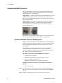
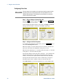
Step 1. Route the load wires through the rear panel.
Push the high current load wires through the rear panel access port.
If you are using remote sensing, route the sense wires though the
second access port. Twist each wire pair.
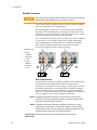
Step 2. Connect the wires to the power module.
Connect the load wires to the output connector of the power module
as shown. Connect the sense wires to the sense connector.
Step 3. Finish the Installation.
Place any unused cable harnesses in the clip ring located between the
power modules and the front panel. Install the top and bottom
covers. Push the covers into place and tighten the thumbscrews.
1. 50 A output
connector
2. Sense
connector
1
2
3. Twist leads
4. To load
3
4
Model N6705 User’s Guide
31
2
Installation
Bench Installation
CAUTION
Do not block the air intake and exhaust at the sides, or the exhaust at the
rear of the unit. Refer to the outline diagram in Appendix A.
Minimum clearances for bench operation are 2 inches (51 mm) along
the sides and back.
For easier display viewing and binding post access, you can tilt the
front of the unit up by rotating the extension bar down.
Rack Installation
CAUTION
Use Rack Mount kit (Option 908 or Option 909 with handles) to rack mount the
instrument. Installation instructions are provided with the rack mount kit.
Agilent N6705 DC Power Analyzer mainframes can be mounted in a
19-inch EIA rack cabinet. They are designed to fit in four rack-units
(4U) of space.
Remove the feet before rack mounting the unit. Do not block the air
intake and exhausts at the sides and rear of the unit.
400 Hz Operation
Redundant Ground Requirement
At 400 Hz AC input operation, the leakage current of the unit exceeds
3.5 mA. This requires the installation of a permanent, redundant
ground from the instrument chassis to earth ground. This ensures
that ground will always be connected and that any leakage current
will be diverted to ground. Refer to the “Connecting the BNC
Connectors” later in this chapter for installation instructions.
Power Factor
Refer to Appendix A for power factor statistics at 400 Hz operation.
32
Model N6705 User’s Guide
Installation
2
Connecting the Line Cord
WARNING
FIRE HAZARD Use only the power cord that was supplied with your
instrument. Using other types of power cords may cause overheating of the
power cord, resulting in fire.
SHOCK HAZARD The power cord provides a chassis ground through a third
conductor. Be certain that your power outlet is of the three-conductor type
with the correct pin connected to earth ground.
Connect the power cord to the IEC 320 connector on the rear of the
unit. If the wrong power cord was shipped with your unit, contact
your nearest Agilent Sales and Support Office.
The AC input on the back of your unit is a universal AC input. It
accepts nominal line voltages in the range of 100 VAC to 240 VAC.
The frequency can be 50 Hz, 60 Hz, or 400 Hz.
NOTE
The detachable power cord may be used as an emergency disconnecting
device. Removing the power cord will disconnect AC input power to the unit.
Connecting the Outputs
WARNING
SHOCK HAZARD Turn off all outputs before making front or rear panel
connections. All wires and straps must be properly connected with the
binding posts securely tightened.
The binding posts accept wires sizes up to AWG 14 in location (A).
The maximum binding post current rating at location (A) is 20 A.
Securely fasten all wires by hand-tightening the binding posts. A
chassis ground binding post is located on the front panel for
convenience.
You can also insert standard banana plugs into the front of the
connectors as shown in (B). The maximum binding post current
rating at location (B) is 15 A.
B
Model N6705 User’s Guide
A
33
2
Installation
Wire Size and Length
WARNING
FIRE HAZARD Select a wire size large enough to carry short-circuit current
without overheating (refer to the table below). To satisfy safety requirements,
load wires must be heavy enough not to overheat while carrying the shortcircuit output current of the unit. Agilent Model N678xA SMU wiring
requirements are described on the following page.
Along with conductor temperature, you must also consider voltage
drop when selecting wire sizes. The following table lists the
resistance for various wire sizes and the maximum lengths to limit
the voltage drop to 1.0 V per lead for various currents.
Note that the minimum wire size required to prevent overheating
may not be large enough to prevent over-voltage tripping or maintain
good regulation. Under most conditions, the load wires should also be
heavy enough to limit the voltage drop to no more than l.0 V per lead.
To help prevent nuisance tripping of the over-voltage circuit, select a
wire size sufficient to handle the FULL output current of the unit no
matter what the intended load current or current limit setting
Load lead resistance is also an important factor relating to the CV
stability of the instrument when remote sensing capacitive loads. If
high capacitance loads are expected, you should not use wire gauges
heavier than 12 to 14 AWG for long runs of load lead.
Wire size
Current-carrying capacity in Amps
for stranded copper wire
Resistance
Max. Length to Limit Voltage to 1 V/Lead
for 5 A
for 10 A
for 20A
for 50 A
AWG
2 wires bundled
4 wires bundled
Ω/foot
Wire length in feet
20
18
16
14
12
10
8
6
7.8
14.5
18.2
29.3
37.6
51.7
70.5
94
6.9
12.8
16.1
25.9
33.2
45.7
62.3
83
0.0102
0.0064
0.0040
0.0025
0.0016
0.0010
0.0006
0.0004
20
30
50
80
125
200
320
504
Area in mm2
2 wires bundled
4 wires bundled
Ω/meter
Wire length in meters
0.5
0.75
1
1.5
2.5
4
6
10
7.8
9.4
12.7
15.0
23.5
30.1
37.6
59.2
6.9
8.3
11.2
13.3
20.8
26.6
33.2
52.3
0.0401
0.0267
0.0200
0.0137
0.0082
0.0051
0.0034
0.0020
5
7.4
10
14.6
24.4
39.2
58
102
x
15
25
40
63
100
160
252
x
x
5
7.2
12.2
19.6
29
51
x
x
x
20
30
50
80
126
x
x
x
x
x
20
32
50
x
x
x
x
6.1
9.8
14.7
25
x
x
x
x
x
3.9
5.9
10.3
Notes: 1. Capacity for AWG wires derived from MIL-W-5088B. Max. ambient temp: 55°C. Max. wire temp: 105°C.
2. Capacity for metric wires are derived from IE Publication 335-1.
3. Capacity of aluminum wire is approximately 84% of that listed for copper wire.
4. “x” indicates wire is not rated for the maximum output current of the power module.
5. Because of wire inductance considerations, it is also recommended that you keep your load leads twisted, tie wrapped,
or bundled together and less than 50 feet (14.7 meters) in length per lead.
34
Model N6705 User’s Guide
Installation
2
Agilent N678xA SMU Wiring Requirements
Because of the effect of wire inductance, the wire length information given in
the previous table does not apply to Agilent Models N678xA SMU.
NOTE
To minimize the effect of wire inductance, the following table
describes the allowable load lead and wire length for several common
cable types. Using longer (or shorter) cable lengths than those
indicated in the table may cause output oscillation.
To N6705 front panel binding post
To N678xA module connector
Cable Type
Length in feet
Length in meters Length in feet
Length in meters
Twisted pair (AWG 14 or smaller)
0 to 3.25 ft
0 to 1 m
1 to 4.25 ft
0.3 to 1.3 m
50 ohm coaxial (RG-58)
0 to 6.5 ft
0 to 2 m
2 to 10 ft
0.6 to 3 m
10 ohm coaxial (inductance per
cable foot ≤ 32 nH)
0 to 26 ft
0 to 8 m
8.5 to 33 ft
2 to 10 m
High Bandwidth Modes with Remote Sensing
The following wiring requirements apply when using Agilent Models
N678xA SMU in the High bandwidth modes with remote sensing.
Refer to chapter 6 under “Output Bandwidth” for more information
about the bandwidth settings.
L
4
< 15 cm
+
-
1
3
CL
N678xA
2
+s
- s
5
1) Load wires must be twisted-pair or coax and must not be twisted
with the sense wires. Refer to the above table for length (L).
2) Sense wires must be twisted-pair or coax and must not be twisted
with the load wires.
3) No capacitors are allowed within the sense-compensated load
path.
4) If the load capacitor (CL) is not located at the sense point, the
distance from the sense point to the load capacitor cannot exceed
15 cm and must be twisted-pair, coax, or pc traces.
5) If the test fixture consists of pc traces, the positive and negative
traces should be directly facing on adjacent layers.
Model N6705 User’s Guide
35
2
Installation
To minimize inductance, the width (w) of the traces should be at
least as great as the thickness of the dielectric (h). It is better to
make the traces much wider than this minimum requirement in
order to minimize the DC resistance.
w
h
Low Bandwidth Mode with Remote or Local Sensing
All previously stated wiring requirements still apply in Low
bandwidth mode except for the following.
The 15 cm maximum limit between the sense point and the load
capacitor (see #4) does not apply when using Low bandwidth mode.
Guard Connection
The purpose of a cable guard is to eliminate the effects of leakage
current that can exist in the current path of the external test circuit.
The cable guard can be used when the test fixture requires guarding
and the DC Power Analyzer is sourcing or measuring DC currents
under 1μA. Without a guard, leakage currents in the test circuit could
affect the accuracy of the micro-ampere measurements. Guarding is
generally not required when measuring currents 1μA and greater.
NOTE
You cannot connect to the front panel binding posts when using the Guard.
You must route ALL wires (guard, load, and sense) through the rear panel
access ports of the N6705B mainframe. Refer to the diagram under “High
Current (50 A) Output Connections” for more information. These access ports
can also be used when extremely precise output measurements are required.
As shown below, cable guards are available at the internal connector
of Agilent Models N678xA SMU. The guard is typically used to drive
the shields of cables and test fixtures. It provides a buffered voltage
that is at the same potential as the + output terminals of the module
connector. The guard current is limited to about 300 μA.
1. Internal
N678xA SMU
connector
- -
G
+ +
+S G -S
GUARD
2. Guard shield
(can be the
shield of a
coaxial cable)
1
2
-
36
+
Model N6705 User’s Guide
Installation
2
Multiple Loads
If you are connecting multiple loads to one output, connect each load
to the output terminals using separate connecting wires as shown.
1. Twist leads
2
2. 4-wire
disabled
(indicator
is off)
1
+
+
This minimizes mutual coupling effects and takes full advantage of
the DC Power Analyzer's low output impedance. Keep each pair of
wires as short as possible and twist or bundle them to reduce lead
inductance and noise pickup. Keep the load leads under 14.7 meters
(50 feet) per lead because of inductance effects.
Agilent Models N678xA SMU have additional wiring restrictions as
discussed under “Agilent N678xA SMU Wiring Requirements”.
If load considerations require the use of distribution terminals that
are located away from the instrument, connect the output terminals
to the remote distribution terminals by a pair of twisted or bundled
wires. Connect each load to the distribution terminals separately. 4wire sensing is recommended under these circumstances. Sense
either at the remote distribution terminals or, if one load is more
sensitive than the others, directly at the critical load.
4-Wire Sense Connections
The DC Power Analyzer includes built-in relays that connect or
disconnect the ± sense terminals from their corresponding ± output
terminals. As shipped, the sense terminals are internally connected
to the output terminals. This is referred to as Local sensing.
4-wire, or remote sensing improves the voltage regulation at the load
by monitoring the voltage at the load rather than at the output
terminals. This automatically compensates for the voltage drop in the
load leads, which is especially useful for CV operation with load
impedances that vary or have significant lead resistance. Because
remote sensing is independent of other DC Power Analyzer functions,
it can be used regardless of how the instrument is programmed.
Remote sensing has no effect during CC operation.
The following figures illustrate load connections using local sensing
(A), and 4-wire remote sensing (B). When the 4-wire indicator above
the sense terminals is on, it indicates that the sense terminals must
be connected to the load.
Model N6705 User’s Guide
37
2
Installation
1. Twist leads
2
3
2. 4-wire
disabled
(indicator
is off)
3. 4-wire
enabled
(indicator
is on)
1
A
+
B
+
Connect the load to the output terminals using separate connecting
wires. Keep the wire-pair as short as possible and twist or bundle it
to reduce lead inductance and noise pickup. Keep the load leads
under 14.7 meters (50 feet) per lead because of inductance effects.
Connect the sense leads as close to the load as possible. Do NOT
bundle the sense wire-pair together with the load leads; keep the load
wires and sense wires separate. The sense leads carry only a few
milliamperes of current and can be a lighter gauge than the load
leads. However, any voltage drop in the sense leads can degrade the
voltage regulation of the instrument. Try to keep the sense lead
resistance less than about 0.5Ω per lead (this requires 20 AWG or
heavier for a 50 foot length).
Agilent Models N678xA SMU require remote sensing when using any
of the High output bandwidth modes discussed in Chapter 6. Also,
these models have additional wiring restrictions as discussed under
“Agilent N678xA SMU Wiring Requirements”.
After turning the unit on, activate 4-wire remote voltage sensing by
pressing the Settings key. Navigate to and select Advanced. In the
Sense dropdown list select 4-Wire.
38
Model N6705 User’s Guide
Installation
2
Open Sense Leads
The sense leads are part of the output's feedback path. Connect them
so that they do not inadvertently open. The DC Power Analyzer has
protection resistors that reduce the effect of open sense leads during
4-wire sensing. If the sense leads open during remote sensing, the
output returns to local sensing mode, with the voltage at the output
terminals approximately 1% higher than the programmed value.
Over-Voltage Protection Considerations
You must take into account any voltage drop in the load leads when
setting the over-voltage trip point. This is because the OVP circuit
senses at the output terminals and not at the sense terminals. Due to
the voltage drop in the load leads, the voltage sensed by the OVP
circuit could be higher than the voltage being regulated at the load.
Note that for Agilent Models N678xA SMU only, the OVP circuit
senses at the 4-wire sense terminals rather than at the output
terminals. This allows for more precise over-voltage monitoring
directly at the load. Since incorrect sense terminal wiring could
defeat this feature, there is also a backup local OVP function.
This local OVP function tracks the programmed OVP setting and trips
if the voltage at the + and − output terminals rises more than 1.5 V
above the programmed OVP setting. The local OVP also trips if the
voltage at the + and - output terminals exceeds 7.5 V on the 6 V range
and 21.5 V on the 20 V range.
Output Noise Considerations
Any noise picked up on the sense leads will appear at the output
terminals and may adversely affect CV load regulation. Twist the
sense leads to minimize the pickup of external noise. In extremely
noisy environments it may be necessary to shield the sense leads.
Ground the shield at the DC Power Analyzer end only; do not use the
shield as one of the sensing conductors.
The noise specifications documented in the Agilent N6700 Modular
Power System Family Specifications Guide apply at the output
terminals when using local sensing. However, voltage transients may
be produced at the load by noise induced in the leads or by load
current transients acting on the inductance and resistance of the
load lead. If it is desirable to keep voltage transient levels to a
minimum, place an aluminum or tantalum capacitor, with an
approximate value of 10 µF per foot (30.5 cm) of load lead, right
across the load.
Model N6705 User’s Guide
39
2
Installation
Parallel Connections
CAUTION
Only connect outputs that have identical voltage and current ratings in parallel.
Agilent Models N678xA SMU cannot be connected in parallel.
Connecting outputs in parallel provides a greater current capability
than can be obtained from a single output.
The following figures show how to connect two outputs in parallel.
The figure on the left illustrates local sensing. If voltage drop in the
load leads is a concern, the figure on the right shows how to connect
the sense leads directly at the load (4-wire sensing).
Once outputs have been connected in parallel, they can be configured
or “grouped” to act as a single, higher-power output. This applies
when programming via the front panel or using SCPI commands.
How to group outputs that have been connected in parallel is
discussed in Chapter 6 under “Output Grouping”.
2
1. Twist leads
3
2. 4-wire
disabled
(indicator
is off)
3. 4-wire
enabled
(indicator
is on)
A
+
B
1
+
Effect on Specifications
Specifications for outputs operating in parallel can be obtained from
the specifications for single outputs. Most specifications are
expressed as a constant or as a percentage (or ppm) plus a constant.
For parallel operation, the percentage portion remains unchanged
while constant portions or any constants are changed as indicated
below. For current readback accuracy and temperature coefficient of
current readback, use the minus current specifications:
Current All parallel specifications referring to current are twice the single output
specification except for programming resolution, which is the same for both
single output and parallel output operation.
Voltage All parallel specifications referring to voltage are the same as for a single
output except for CV load effect, CV load cross regulation, CV source effect,
and CV short term drift. These are all twice the voltage programming accuracy
(including the percentage portion) at all operating points.
Load Transient Load transient specifications are typically twice the single output.
Recovery Time
40
Model N6705 User’s Guide
Installation
2
Series Connections
WARNING
SHOCK HAZARD Floating voltages must not exceed 240 VDC. No output
terminal may be more than 240 VDC from chassis ground.
CAUTION
Only connect outputs that have identical voltage and current ratings in series.
Agilent Models N678xA SMU and N6783A–x cannot be connected in series.
To prevent reverse currents from damaging the DC Power Analyzer when the
load is connected, always turn series-connected outputs on and off together.
Do not leave one output on while the other is off.
NOTE
You can only use the series-connected outputs in “standard” power supply
mode. You cannot generate arbitrary waveforms, make scope measurements or
use data logging on outputs that are connected in series.
Connecting outputs in series provides a greater voltage capability
than can be obtained from a single output. Because the current is the
same through each element in a series circuit, outputs connected in
series must have equivalent current ratings.
The following figures show how to connect two outputs in series to a
single load. If voltage drop in the load leads is a concern, connect the
sense leads of output 1 and output 2 for remote sensing as shown in
the figure on the right. Connecting the +S terminal of output 2 to the
-S terminal of output 1 and connecting a jumper between +S and + on
output 2 compensates for the IR drop in the load lead from output 2
to output 1.
2
1. Twist leads
3
2. 4-wire
disabled
(indicator
is off)
3. 4-wire
enabled
(indicator
is on)
A
+
Model N6705 User’s Guide
B
1
+
41
2
Installation
To program outputs connected in series, first program the current
limit of each output to the total desired current limit point. Then
program the voltage of each output so that the sum of both voltages
equals the total desired operating voltage. The simplest way to
accomplish this is to program each output to one half of the total
desired operating voltage.
NOTE
The operating mode of each output is determined by the output’s programmed
settings, operating point, and load condition. Because these conditions may
change during series operation, the operating status indicators on the front
panel will reflect these changes. This is normal. Momentary status changes are
also normal.
Effect on Specifications
Specifications for outputs operating in series can be obtained from
the specifications for single outputs. Most specifications are
expressed as a constant or a percentage (or ppm) plus a constant.
For series operation, the percentage portion remains unchanged
while constant portions or any constants are changed as indicated.
Voltage
All series specifications referring to voltage are twice the single output
specification except for programming resolution, which is the same as for a
single output.
Current
All series specifications referring to current are the same as for a single
output except for CC load effect, CC load cross regulation, CC source effect,
and CC short term drift. These are twice the current programming accuracy
(including the percentage portion) at all operating points.
Load Transient
Recovery Time
Load transient specifications are typically twice the single output.
Additional Load Considerations
Response Time with an External Capacitor
When programming with an external capacitor, voltage response time
may be longer than that for purely resistive loads. Use the following
formula to estimate the additional up-programming response time:
Response Time = (Added Output Capacitor)X(Change in Vout)
(Current Limit Setting)−(Load Current)
Note that programming into an external output capacitor may cause
the DC Power Analyzer to briefly enter constant current or constant
power operating mode, which adds additional time to the estimation.
42
Model N6705 User’s Guide
Installation
2
Positive and Negative Voltages
Either positive or negative voltages with respect to ground can be
obtained from the output by grounding (or "commoning") one of the
output terminals. Always use two wires to connect the load to the
output regardless of where or how the system is grounded. The
instrument can be operated with any output terminal ± 240 VDC
including output voltage from ground.
NOTE
Agilent Models N678xA SMU are optimized for grounding the negative output
terminal. Grounding the positive terminal may result in increased current
measurement noise and a reduction in current measurement accuracy.
Protecting Sensitive Loads from AC Power Switching Transients
NOTE
If your load is connected directly to the output binding posts and is not
connected to chassis ground in any way, you do not need to worry about AC
power switching transients appearing at the output binding posts.
Operating the AC line switch can inject common mode current spikes
into the DC output leads, resulting in voltage spikes that may damage
loads that are highly sensitive to voltage or current transients. Note
that any electronic device meeting international standards for EMI
compliance is likely to generate similar current spikes. This situation
arises from the presence of EMI filters at both the AC input and the
DC output. These filters typically include common mode capacitors
connected to the chassis of the DC Power Analyzer. Since the AC
input has an earth ground, any load that is also earth-grounded
provides a possible return path for common mode currents.
The following steps will help mitigate common mode current spikes
appearing at the output binding posts when the DC Power Analyzer
is turned on or off by the AC line switch:
Model N6705 User’s Guide
Install a separate “bonding” wire from the load’s common point,
to the ground terminal of the DC Power Analyzer. This provides a
lower impedance path that helps direct injected currents away
from the DC output leads (and the sensitive load).
Disconnect the load from the output before turning the unit on or
off. This always protects the load from common mode currents.
43
2
Installation
Connecting the BNC Connectors
The rear panel BNC connectors let you apply trigger signals to the
instrument as well as generate trigger signals from the instrument.
This also applies to the digital port.
Trigger Input - Allows a negative-going external signal to trigger the
instrument. The signal must have a minimum pulse width of two
microseconds. Trigger input signals are used by the Arb, Scope, and
Data Logger functions.
Trigger Output - Generates a negative-going 10 microsecond pulse
when a triggered event has occurred on the instrument. Trigger
output signals can be generated by the user-defined voltage or
current Arb functions.
Information on configuring external triggers is found in Appendix C.
The electrical characteristics are described in Appendix A.
Installing a Redundant Ground for 400 Hz Operation
Operation at 400 Hz requires the installation of a redundant ground
from the instrument chassis to earth ground. The redundant ground
must be permanently attached to the unit as well as to the earth
ground point.
The following procedure describes how to make the permanent
connection at the unit using one of the two rear panel BNC
connectors. The user must ensure the integrity and permanence of
the connection at the earth ground point.
The following customer-supplied hardware is required:
Ground wire (14/16 AWG)
Uninsulated ring terminal for attaching wire to unit
(Tyco p/n 328976 or equivalent)
Hardware for attaching wire to earth ground point
The following tools are required for installing the redundant
ground:
5/8 inch nut driver
Step 1. Use the nut driver and remove the hex nut (1) from only one of the
BNC connectors. Do not remove the lock washer located behind the
hex nut.
Step 2. Crimp the ring terminal (2) onto the end of the ground wire.
44
Model N6705 User’s Guide
Installation
2
Step 3. Place the ring terminal onto the threaded BNC connector. Make sure
that the lock washer (3) is in place before installing the ring terminal.
Step 4. Tighten the hex nut onto the ring terminal.
Step 5. Attach the other end of the redundant ground wire to a convenient
earth ground point.
3
1
2
Connecting the Digital Port
NOTE
It is good engineering practice to twist and shield all signal wires to and from
the digital connectors. If shielded wire is used, connect only one end of the
shield to chassis ground to prevent ground loops.
An 8-pin connector and a quick-disconnect connector plug are
provided for accessing the digital port functions. The connector plug
accepts wires sizes from AWG 14 to AWG 30. Wire sizes smaller than
AWG 24 are not recommended. Disconnect the connector plug to
make your wire connections.
1. Insert wires
1
2
3
4
5
6
7
2
I
2. Tighten screws
3. Signal common
4. Digital I/O signals
5. FLT/INH signals
6. Output Couple
controls
+ -
1
3
4
5
6
Information on configuring the digital port is found in Appendix C.
The electrical characteristics are described in Appendix A.
Model N6705 User’s Guide
45
2
Installation
Connecting the Auxiliary Voltage Measurement Input
NOTE
This information applies to Agilent Model N6781A only.
The auxiliary voltage measurement input is located on the rear panel
of the Agilent N6705B. It is primarily used for battery voltage
rundown measurements, but it is also suitable for general purpose
DC measurements between ±25 VDC. As shown in the following
figure, auxiliary voltage measurements cannot be made on test points
that are at a greater potential than ±25 VDC from Common.
Refer to chapter 4 under “Agilent N6781A Auxiliary Voltage
Measurements” for more information.
CAUTION
When using the auxiliary voltage measurement input on Model N6781A, no
front panel output terminal or rear panel input terminal may be more than ± 60
VDC from any other terminal and chassis ground.
A. Aux Voltage
Measurement
input
B. Test Fixture
1. 36 V
2. 24 V
3. 12 V
4. Com.
5. –12 V
6. –24 V
7. –36 V
46
Model N6705 User’s Guide
Installation
2
Connecting to the Interfaces
The DC Power Analyzer supports GPIB, LAN, and USB interfaces. All
three interfaces are live at power-on. Connect your interface cable to
the appropriate interface connector. Information on configuring the
interfaces is found later in this chapter.
The front panel IO indicator comes on whenever there is activity on
the interfaces. The front panel LAN indicator comes on when the
LAN port is connected and configured.
The DC Power Analyzer provides Ethernet connection monitoring.
With Ethernet connection monitoring, the instrument’s LAN port is
continually monitored, and automatically reconfigured when the
instrument is unplugged for a minimum of 20 seconds and then
reconnected to a network.
GPIB/USB Interfaces
NOTE
For detailed information about GPIB and USB interface connections, refer to the
Agilent Technologies USB/LAN/GPIB Interfaces Connectivity Guide, located on
the Automation-Ready CD that is shipped with your product.
The following steps will help you quickly get started connecting your
instrument to the GPIB (General Purpose Interface Bus). The
following figure illustrates a typical GPIB interface system.
Model N6705 User’s Guide
1
If you have not already done so, install the Agilent IO Libraries
Suite from the Automation-Ready CD that is shipped with your
product.
2
If you do not have a GPIB interface card installed on your
computer, turn off your computer and install the GPIB card.
3
Connect your instrument to the GPIB interface card using a GPIB
interface cable.
4
Use the Connection Expert utility of the Agilent IO Libraries
Suite to configure the installed GPIB interface card’s parameters.
5
The DC Power Analyzer is shipped with its GPIB address set to 5.
To view or change the GPIB address, press the Menu key, select
Utilities, then I/O Configuration, then GPIB/USB.
47
2
Installation
To change the GPIB address, use the numeric keys to enter a
value in the GPIB address field. Valid addresses are from 0 to 30.
Press Enter to enter the value.
6
You can now use Interactive IO within the Connection Expert to
communicate with your instrument, or you can program your
instrument using the various programming environments.
The following steps will help you quickly get started connecting your
USB-enabled instrument to the USB (Universal Serial Bus). The
following figure illustrates a typical USB interface system.
1
If you have not already done so, install the Agilent IO Libraries
Suite from the Automation-Ready CD that is shipped with your
product.
2
Connect the USB device port located on the back of your
instrument to the USB port on your computer.
3
With the Connection Expert utility of the Agilent IO Libraries
Suite running, the computer will automatically recognize the
instrument. This may take several seconds. When the instrument
is recognized, your computer will display the VISA alias, IDN
string, and VISA address. This information is located in the USB
folder.
You can also view the instrument’s VISA address from the front
panel. Use the front panel menu to access the GPIB/USB window
as described above. The VISA address is shown in the connect
string field.
4
48
You can now use Interactive IO within the Connection Expert to
communicate with your instrument, or you can program your
instrument using the various programming environments.
Model N6705 User’s Guide
Installation
2
LAN Interface
NOTE
For detailed information about LAN interface connections, refer to the Agilent
Technologies USB/LAN/GPIB Interfaces Connectivity Guide, located on the
Automation-Ready CD that is shipped with your product.
The following steps will help you quickly get started connecting and
configuring your instrument on a local area network. The two types
of local area networks connections that are discussed in this section
are site networks and private networks.
Connecting to a Site LAN
A site LAN is a local area network in which LAN-enabled instruments
and computers are connected to the network through routers, hubs,
and/or switches. They are typically large, centrally-managed
networks with services such as DHCP and DNS servers.
NOTE
1
If you have not already done so, install the Agilent IO Libraries
Suite from the Automation-Ready CD that is shipped with your
product.
2
Connect the instrument to the site LAN. The factory-shipped
instrument LAN settings are configured to automatically obtain
an IP address from the network using a DHCP server (DHCP is
set On). Note that this may take up to one minute. The DHCP
server will register the instrument’s hostname with the dynamic
DNS server. The hostname as well as the IP address can then be
used to communicate with the instrument. The front panel LAN
indicator will come on when the LAN port has been configured.
If you need to manually configure any instrument LAN settings, refer to
“Configuring the LAN Parameters” later in this chapter for information about
configuring the LAN settings from the front panel of the instrument.
3
NOTE
Model N6705 User’s Guide
Use the Connection Expert utility of the Agilent IO Libraries
Suite to add the N6705 DC Power Analyzer and verify a
connection. To add the instrument, you can request the
Connection Expert to discover the instrument. If the instrument
cannot be found, add the instrument using the instrument’s
hostname or IP address.
If this does not work, refer to the chapter on “Troubleshooting Guidelines” in
the Agilent Technologies USB/LAN/GPIB Interfaces Connectivity Guide.
49
2
Installation
4
You can now use Interactive IO within the Connection Expert to
communicate with your instrument, or you can program your
instrument using the various programming environments. You
can also use the Web browser on your computer to connect to the
instrument as described under “Connecting to the Web Server”.
Connecting to a Private LAN
A private LAN is a network in which LAN-enabled instruments and
computers are directly connected, and not connected to a site LAN.
They are typically small, with no centrally-managed resources.
NOTE
NOTE
50
1
If you have not already done so, install the Agilent IO Libraries
Suite from the Automation-Ready CD that is shipped with your
product.
2
Connect the instrument to the computer using a LAN crossover
cable. Alternatively, connect the computer and the instrument to
a standalone hub or switch using regular LAN cables.
Make sure your computer is configured to obtain its address from DHCP and that
NetBIOS over TCP/IP is enabled. Note that if the computer had been connected to a
site LAN, it may still retain previous network settings from the site LAN. Wait one
minute after disconnecting it from the site LAN before connecting it to the private
LAN. This allows Windows to sense that it is on a different network and restart the
network configuration. (Windows 98 requires you to manually release the settings.)
3
The factory-shipped instrument LAN settings are configured to
automatically obtain an IP address from a site network using a
DHCP server, then to automatically choose an IP address using
auto-IP if a DHCP server is not present. The instrument and
computer are each assigned an IP address from the block
169.254.nnn. Note that this may take up to one minute. The front
panel LAN indicator will come on when the LAN port has been
configured.
4
Use the Connection Expert utility of the Agilent IO Libraries
Suite to add the N6705 DC Power Analyzer and verify a
connection. To add the instrument, you can request the
Connection Expert to discover the instrument. If the instrument
cannot be found, add the instrument using the instrument’s
hostname or IP address.
If this does not work, refer to the chapter on “Troubleshooting Guidelines” in the
Agilent Technologies USB/LAN/GPIB Interfaces Connectivity Guide.
Model N6705 User’s Guide
Installation
5
2
You can now use Interactive IO within the Connection Expert to
communicate with your instrument, or you can program your
instrument using the various programming environments. You
can also use the Web browser on your computer to connect to the
instrument as described under “Connecting to the Web Server”.
Viewing the Active LAN Status
To view the currently active LAN settings, press the Menu key, scroll
down and select the Utilities, then select I/O Configuration, then
Active LAN Status.
Note that the currently active LAN settings for the IP Address,
Subnet Mask, and Default Gateway may be different from the settings
specified in the “Modify LAN Settings” window - depending on the
configuration of the network. If the settings are different, it is
because the network has automatically assigned its own settings.
Modifying the LAN Settings
As shipped from the factory, the DC Power Analyzer’s pre-configured
settings should work in most LAN environments. If you need to
manually configure these settings, press the Menu key, scroll down
and select Utilities, then I/O Configuration, then LAN Settings.
NOTE
Either the Restart LAN button must be selected, or the DC Power Analyzer must
be rebooted for any LAN parameter modifications to take effect.
You can configure the following items in the LAN Settings window:
Model N6705 User’s Guide
51
2
Installation
Get IP Address
Automatically
With this box checked, the instrument will first try to obtain an IP address
from a DHCP server. If a DHCP server is found, the DHCP server will assign
an IP address, Subnet Mask, and Default Gateway to the instrument. If a
DHCP server is unavailable, the instrument will try to obtain an IP address
using AutoIP. AutoIP automatically assigns an IP address, Subnet Mask,
and Default Gateway on networks that do not have a DHCP server.
With this box unchecked, you can configure the addresses manually by
entering values in the following three fields.
IP Address
Subnet Mask
Default
Gateway
Host Name
This value is the Internet Protocol (IP) address of the instrument. An IP
address is required for all IP and TCP/IP communications with the
instrument. An IP Address consists of 4 decimal numbers separated by
periods. Each decimal number ranges from 0 through 255.
This value is used to enable the instrument to determine if a client IP
address is on the same local subnet. When a client IP address is on a
different subnet, all packets must be sent to the Default Gateway.
This value is the IP Address of the default gateway that allows the
instrument to communicate with systems that are not on the local subnet,
as determined by the subnet mask setting. A value of 0.0.0.0 indicates that
no default gateway is defined.
This field registers the supplied name with the selected naming service. If
the field is left blank, no name is registered. A hostname may contain upper
and lower case letters, numbers and dashes(-). The maximum length is 15
characters. Use the numeric/alpha keys to enter letters or numbers.
Repeatedly pressing a key cycles through the list of choices. After a short
delay the cursor automatically moves to the right.
Each DC Power Analyzer is shipped with a default hostname with the
format: A-modelnumber-serialnumber, where modelnumber is the
mainframe’s 6-character model number (e.g. N6705B), and serialnumber is
the last five characters of the 10-character mainframe serial number located
on the label on the top of the unit (e.g. 45678 if the serial number is
MY12345678). A-N6705B-45678 is an example of a hostname.
Use Dynamic
DNS naming
Registers the hostname using the Dynamic DNS naming system.
Use NetBIOS
naming
Registers the hostname using the RFC NetBIOS naming protocol.
Domain Name
52
Registers the Internet domain for the instrument. This is required if your
DNS server requires an instrument to register not only the hostname, but
also the domain name. The Domain must start with a letter and may contain
upper and lower case letters, numbers, dashes(-) and dots(.). Use the
numeric/alpha keys to enter letters or numbers. Repeatedly pressing a key
cycles through the list of choices. After a short delay the cursor
automatically moves to the right.
Model N6705 User’s Guide
Installation
Obtain DNS
server from
DHCP
DNS is an internet service that translates domain names into IP addresses.
It is also needed for the instrument to find and display its hostname
assigned by the network. Check this item to obtain the DNS server address
from DHCP. You must have previously checked Get IP Address
Automatically.
DNS server
This value is the address of the DNS server. It is used if you are not using
DHCP or if you need to connect to a specific DNS server.
Enable TCP
Keepalive
Check the Enable box to enable the TCP keepalive function. The instrument
uses the TCP keepalive timer to determine if a client is still reachable. If
there has been no activity on the connection after the specified time, the
instrument will send keepalive probes to the client to determine if it is still
alive. If not, the connection will be marked as down or "dropped." The
instrument will release any resources that were allocated to that client.
Timeout
This is the delay in seconds before TCP keepalive probes will be sent to the
client. It is recommended that the largest value be used that still meets the
application's need for unreachable client detection. Smaller keepalive timeout values will generate more keepalive probes (network traffic), using more
of the available network bandwidth. Allowed values: 720 - 99999 seconds.
Default
Settings
Resets the LAN settings to the factory-shipped state. These settings are listed at the
end of chapter 1.
Restart LAN
Model N6705 User’s Guide
2
Restarts networking to use the modified configuration settings.
53
2
Installation
Communicating Over the LAN
Using the Web Server
Your Agilent N6705 DC Power Analyzer has a built-in Web server that
lets you control it directly from an internet browser on your
computer. Up to two simultaneous connections are allowed. With
additional connections, performance will be reduced.
With the Web server, you can access the front panel control functions
including the LAN configuration parameters. This is a convenient
way to communicate with the DC Power Analyzer without using I/O
libraries or drivers.
NOTE
The built-in Web server only operates over the LAN interface. It requires Internet
Explorer 7+ or Firefox 2+. You also need the Java (Sun) Plug-in. This is included
in the Java Runtime Environment. Refer to Sun Microsystem’s website. If you are
using Internet Explorer 7, open a separate browser window for each connection.
The Web server is enabled when shipped. To launch the Web server:
1
Open the internet browser on your computer.
2
Enter the instrument’s hostname or IP address into the browser’s
Address field to launch the Web server. The following home page
will appear:
3
Click on the Browser Web Control button in the navigation bar
on the left to begin controlling your instrument.
4
For additional help about any page, click Help with this Page.
If desired, you can control access to the Web server using password
protection. As shipped from the factory, no password is set. To set a
password, click on the View & Modify Configuration button. Refer to
the on-line help for additional information about setting a password.
54
Model N6705 User’s Guide
Installation
2
Using Telnet
The Telnet utility (as well as sockets), is another way to communicate
with the DC Power Analyzer without using I/O libraries or drivers. In
all cases, you must first establish a LAN connection from your
computer to the DC Power Analyzer as previously discussed.
In an MS-DOS Command Prompt box type: telnet hostname 5024
where hostname is the N6705 hostname or IP address, and 5024 is
the instrument’s telnet port. You should get a Telnet session box with
a title indicating that you are connected to the DC Power Analyzer.
Type the SCPI commands at the prompt.
Using Sockets
NOTE
Agilent N6705 mainframes allow any combination of up to four simultaneous
data socket, control socket, and telnet connections to be made.
Agilent instruments have standardized on using port 5025 for SCPI
socket services. A data socket on this port can be used to send and
receive ASCII/SCPI commands, queries, and query responses. All
commands must be terminated with a newline for the message to be
parsed. All query responses will also be terminated with a newline.
The socket programming interface also allows a control socket
connection. The control socket can be used by a client to send device
clear and to receive service requests. Unlike the data socket, which
uses a fixed port number, the port number for a control socket varies
and must be obtained by sending the following SCPI query to the data
socket: SYSTem:COMMunicate:TCPip:CONTrol?
After the port number is obtained, a control socket connection can be
opened. As with the data socket, all commands to the control socket
must be terminated with a newline, and all query responses returned
on the control socket will be terminated with a newline.
To send a device clear, send the string “DCL” to the control socket.
When the DC Power Analyzer has finished performing the device
clear it echoes the string “DCL” back to the control socket.
Service requests are enabled for control sockets using the Service
Request Enable register. Once service requests have been enabled,
the client program listens on the control connection. When SRQ goes
true the instrument will send the string “SRQ +nn” to the client. The
“nn” is the status byte value, which the client can use to determine
the source of the service request.
Model N6705 User’s Guide
55
Agilent N6705 DC Power Analyzer
User’s Guide
3
Using the Source Functions
Turning the Unit On .......................................................................................... 58
Using the Power Supply ................................................................................... 60
Using the Arbitrary Waveform Generator ..................................................... 75
This chapter contains examples on how to operate your DC Power
Analyzer. The examples provided show you how to use the:
Power supply function
Arbitrary waveform generator
Equivalent SCPI commands to program a specific function are
included at the end of each topic. However some functions such as
the front panel Scope View, Data Logger View, and some
Administrative functions do not have equivalent SCPI commands.
Appendix B lists all of the SCPI commands that can be used to
program the instrument.
NOTE
For complete details on using the SCPI commands, refer to the Programmer’s
Reference Help file included on the Agilent N6705 Product Reference CD. This
CD-ROM is shipped along with your instrument.
57
3
Using the Source Functions
Turning the Unit On
After you have connected the line cord, turn the unit on using the
Line switch. The front panel display lights up after a few seconds.
When the front panel Meter View appears, use the front panel knobs
to enter voltage and current values. Output 1 is selected by default.
Press one of the four On keys to enable an individual output. In
Meter View the DC Power Analyzer continuously measures and
displays the output voltage and current of each output.
A power-on self-test occurs automatically when you turn the unit on. This test
assures you that the instrument is operational. If the self-test fails, the front
panel will display any errors.
NOTE
View the Error Log
The front panel Error indicator comes on if self-test fails or if other
operating problems occur with your instrument. To display the error
list, press the Menu key, scroll and select Utilities, then Error Log.
58
Errors are stored in the order they are received. The error at the
end of the list is the most recent error.
If there are more errors than can fit in the queue, the last error
stored is replaced with -350,"Error queue overflow". No more
errors are stored until you remove errors from the queue. If there
are no errors, the instrument responds with +0,"No error".
Except for self-test errors, all errors are cleared when you exit
the Error Log menu or when power is cycled.
Model N6705 User’s Guide
Using the Source Functions
3
If you suspect that there is a problem with the DC Power Analyzer,
refer to the troubleshooting section in the N6705 Service Guide. The
Service Guide is included as part of the optional Manual Set (Option
0L1). An electronic copy of the N6705 Service Guide is also included
on the N6705 Product Reference CD-ROM.
Press Meter View to return to the meter view.
View Output Ratings
You can quickly view the output ratings, model numbers and options
of all power modules installed in your instrument. You can also view
the mainframe serial number and firmware revisions. Press the
Settings key and then press the Properties key. The Power Supply
Ratings window will appear.
Press Meter View to return to the meter view.
From the remote interface:
To return the model number, serial number, and firmware revisions
of the mainframe:
*IDN?
To return the model number, serial number, installed options,
voltage, current and power rating of the module installed in the
specified channel location:
SYST:CHAN:MOD? (@1)
SYST:CHAN:OPT? (@1)
SYST:CHAN:SER? (@1)
Model N6705 User’s Guide
59
3
Using the Source Functions
Using the Power Supply
Controlling the Outputs
NOTE
The figures on the right apply to Agilent Models N678xA SMU.
Step 1 – Select an output:
Press one of the Select Output keys to select an output to control. The
lit key identifies the selected output. All subsequent output-specific
front panel commands are sent to the selected output.
Step 2 – Set the output voltage and current:
Turn the Voltage and Current knobs. The output voltage or current
setting changes when they are turned. These knobs are active in
Meter View, Scope View, and Data Logger mode.
Push the voltage and current knobs to access a
pop-up dialog that lets you: 1. Lock/Unlock the
knobs. 2. Select limit parameters or select limit
tracking on Agilent N678xA SMU and N6783A.
You can also enter the voltage and current values directly in the
numeric entry fields (the Set fields) in the Meter-view display. Use
the navigation keys to select the field; use the numeric entry keys to
enter the value. The value becomes active when you press Enter.
Lastly, you can press the Settings key to access the Source Settings
window. Use the navigation keys to highlight the Voltage or Current
fields. Then enter the voltage and current values with the numeric
keys. You can use the Voltage and Current knobs to adjust the values
in the Voltage and Current fields. Press Enter to enter the value.
60
Model N6705 User’s Guide
Using the Source Functions
3
Step 3 – Enable the output:
Press the color-coded On key to enable an individual output. When
an output is on, the On key for that output is lit. When an output is
Off, the On key is not lit. The All Outputs On and Off keys turn all
outputs on or off simultaneously.
The state of a disabled output (output off) is a condition of zero
output voltage and zero source current.
NOTE
The red Emergency Stop key turns all outputs off immediately without any
output off delays.
Step 4 – View the output voltage and current:
Select Meter View to view the output voltage and current. When an
output is enabled, the front panel meters continuously measure and
display the output voltage and current.
From the remote interface:
A channel parameter is required with each SCPI command to select
an output. For example, (@1) selects output 1, (@2,4) selects output 2
and 4, and (@1:4) selects outputs 1 through 4. The output list must be
preceded with an @ symbol and be enclosed in parentheses ().
To set only output 1 to 10.02 V and 1 A:
VOLT 10.02,(@1)
CURR 1,(@1)
To set the output current limit to 1 A for Agilent Models N678xA SMU
and N6783A:
CURR:LIM 1,(@1)
To set the output voltage of all outputs to 10 V:
VOLT 10.02,(@1:4)
To enable only output 1:
OUTP ON,(@1)
To enable output 1 and output 3:
OUTP ON,(@1,3)
To measure the output voltage and current of output 1:
MEAS:VOLT? (@1)
MEAS:CURR? (@1)
Model N6705 User’s Guide
61
3
Using the Source Functions
Additional Source Settings
In addition to setting the output voltage and current as previously
discussed, you can program a number of additional output functions.
Press the Settings key to access the Source Settings window.
Voltage or Current Range - For outputs with multiple ranges, you
can select a lower range if you need better output resolution. Use the
navigation keys to highlight either the voltage or current Range field.
Press the Enter key to access the dropdown range list. Use the
navigation keys to select the desired output range.
Turn-on Pref - The turn-on preference function only applies to
Agilent Models N6761A, N6762A. This specifies the preferred mode
for output on/off transitions. It allows output state transitions to be
optimized for either constant voltage or constant current operation.
In the Turn-on Pref drop-down list, select either Voltage or Current.
Selecting Voltage minimizes output on/off voltage overshoots in
constant voltage operation. Selecting Current minimizes output
on/off current overshoots in constant current operation.
Reverse Polarity – This control only applies if the power module has
Option 760 installed. Check Reverse Polarity to reverse the polarity
of the output terminals and the sense terminals. Uncheck to return
the relay polarity to normal. The output is briefly turned off while the
output and sense terminal polarities are switched. Note that when
this option is installed, the maximum output current is limited to
10A. When the output and sense polarities are reversed, the following
symbol appears on the front panel display:
From the remote interface:
To select a lower voltage or current range on output 1, program a
value that falls within the range:
VOLT:RANG 5,(@1)
CURR:RANG 1,(@1)
To set the Agilent N6761A turn on preference to current priority:
OUTP:PMOD CURR,(@1)
To reverse the relay polarity on units with Option 760:
OUTP:REL:POL REV,(@1)
To return the relay polarity to normal:
OUTP:REL:POL NORM,(@1)
62
Model N6705 User’s Guide
Using the Source Functions
3
Agilent N678xA SMU Emulation Settings
NOTE
The Source Settings window lets you access the specialized operating modes
of the Agilent Models N678xA SMU when these power modules are installed.
The Emulating dropdown list lets you access the specialized
operating modes of the Agilent Models N678xA SMU. Use the
navigation keys to select one of the emulating modes.
NOTE
Information about the Voltage Measure Only and Current Measure Only modes is
discussed in chapter 4.
4-Quadrant Power Supply
4-quadrant operation is only available on Agilent Model N6784A.
Operation is allowed in all four output quadrants. Refer to Chapter 6
under “Priority Mode Operation” for more information. The following
figures show the 4-quadrant settings.
Operating in – selects either Voltage Priority or Current Priority. In
voltage priority the output is controlled by a bi-polar constant voltage
feedback loop, which maintains the output voltage at its positive or
negative setting. In current priority the output is controlled by a bipolar constant current feedback loop, which maintains the output
source or sink current at its programmed setting.
NOTE
Model N6705 User’s Guide
When switching between Voltage Priority and Current Priority, the output is
turned off and the output settings revert to their Power-on or RST values. Refer
to chapter 6 for a detailed description of voltage and current priority.
63
3
Using the Source Functions
Depending on the priority mode, you can specify either the output
Voltage or output Current setting. The Range function lets you select
the appropriate output range. You can also specify a Voltage Limit or
Current Limit, which limits the selected parameter at the specified
value. In voltage priority mode, the output voltage remains at its
programmed setting as long as the load current is within the positive
or negative limit. In current priority mode, the output current
remains at its programmed setting as long as the output voltage is
within the positive or negative limit.
Tracking Limits lets the negative voltage or current limit track the
positive voltage or current limit setting. By default, the negative limit
will track the positive limit value. Un-check this box if you want to
program asymmetrical positive and negative limits. If asymmetrical
limits are programmed and tracking is turned on, the negative value
is changed to track the positive limit.
2-Quadrant Power Supply
This operating mode is restricted to two quadrants (+V/+I and +V/- I).
The following figures show the 2-quadrant settings.
Operating in – selects either Voltage Priority or Current Priority. The
other settings in 2-quadrant mode are the same as the settings in 4quadrant mode except that you cannot program negative voltages or
negative voltage limits. Because of this, voltage tracking is not
available in Current Priority mode. Note that the negative voltage
limit is fixed at –10 mV.
Resistance - This is only available on Agilent Model N6781A. Output
resistance programming is primarily used in battery emulation
applications, and only applies in Voltage Priority mode. Values are
programmed in Ohms, from –40 mΩ to +1 Ω.
1-Quadrant Power Supply (unipolar)
This mode emulates a typical one quadrant or unipolar power supply
with limited down-programming. The following figures show the 1quadrant settings. The Voltage Priority and Current Priority
selections determine which controls are displayed.
In 1-quadrant mode you cannot program negative voltages, negative
currents, negative voltage limits, or negative current limits. Because
of this, voltage tracking and current tracking are not available. Note
that there is limited 2-quadrant operation with the negative current
limit being fixed at 10% to 20% of the output current rating.
64
Model N6705 User’s Guide
Using the Source Functions
3
Resistance - This is only available on Agilent Model N6781A. Output
resistance programming is primarily used in battery emulation
applications, and only applies in Voltage Priority mode. Values are
programmed in Ohms, from – 40 mΩ to + 1 Ω.
Battery Emulator/Battery Charger
Battery emulator and battery charger modes are only available on
Agilent Model N6781A. A battery emulator imitates a battery’s
charging and discharging functions. A battery charger imitates a
battery charger; it cannot sink current like a battery. The following
figures show the Battery emulator/Battery charger settings.
In Battery Emulator mode you can specify the battery voltage and
range as well as the + and – current limits. The output resistance is
programmable, from – 40 mΩ to + 1 Ω. Voltage Priority mode is
locked. The voltage setting is limited to positive values. The + and –
current limits are set to their maximum values. The – current limit
setting sets the current limit when the battery is being charged.
In Battery Charger mode, you can specify the charge voltage and
range as well as the positive current limit. Voltage Priority mode is
locked. Because the battery charger can only source current, the
voltage and current settings are limited to positive values.
Model N6705 User’s Guide
65
3
Using the Source Functions
CC Load/CV Load
The CC Load emulates a constant-current load. The CV Load
emulates a constant-voltage load. The figures below show the CC and
CV load settings.
In CC load mode you can specify the input Current and Range as well
as the + Voltage Limit. Current Priority mode is locked. Remember to
set the input current to a negative value. The + Voltage Limit should
normally be set to its maximum value. The – Voltage limit is not
programmable. In Meter mode, the measurement polarities and
current settings are shown as negative values.
In CV load mode you can specify the input Voltage and Range as well
as the – Current Limit. Voltage Priority mode is locked. Set the input
voltage to a positive value. The – Current Limit should normally be
set to its maximum negative value. The + Current Limit is not
programmable. In Meter mode, the measurement polarities and
current settings are shown as negative values.
From the remote interface:
To specify the 4-quadrant, 2-quadrant, or 1-quadrant power supply
emulation setting:
EMUL PS4Q,(@1)
EMUL PS2Q,(@1)
EMUL PS1Q,(@1)
To set the voltage priority mode:
FUNC VOLT,(@1)
To set the output voltage to 5 V and the low voltage range:
VOLT 5,(@1)
RANG 6,(@1)
To set the positive current limit of output 1 to 1 A:
CURR:LIM 1,(@1)
To set the negative current limit, you must first turn limit coupling
(tracking) off. Then set the negative current limit to 0.5 A:
CURR:LIM:COUP OFF,(@1)
CURR:LIM:NEG 0.5,(@1)
66
Model N6705 User’s Guide
Using the Source Functions
3
Configuring a Turn-On/Turn-Off Sequence
Turn-on and turn-off delays control the turn-on and turn-off timing of
the outputs in relation to each other.
NOTE
You can also synchronize Output On/Off delays across multiple mainframes.
Refer to Appendix C under “Output Couple Controls” for further information.
Step 1 – Set the output voltage and current of the output channels:
Refer to steps 1 and 2 under “Controlling the Outputs” and set the
output voltage and current values of all outputs that will be
sequenced.
Step 2 – Configure the turn-on turn-off delays:
Press the Settings key twice to access the Output On/Off Delays
window. Enter the On Delays and Off Delays for all outputs that will
participate in the output on/off delay sequence. Values can range
from 0 to 1023 seconds.
All power modules have an internal turn-on delay that applies from
the time that the command to turn on the output is received until the
output actually turns on. This turn-on delay is automatically added to
the On Delays values. The turn-on delay does not apply when outputs
turn off. To view the delay, select the Output Coupling button.
Normally, the firmware automatically calculates the delay offset
based on the longest minimum turn-on delay of the installed power
modules. However, if you will be excluding some outputs from
participating in an output on/off delay sequence as described Step 3,
the delay offset may be different based on the outputs that you will
actually be sequencing. The minimum turn-on delays of the power
modules are documented in the Agilent N6700 Modular Power
System Family Specifications Guide.
Model N6705 User’s Guide
67
3
Using the Source Functions
Step 3 – Coupling selected outputs:
NOTE
This step is only required if you will be excluding some outputs from
participating in an output on/off delay sequence, or if you are coupling multiple
mainframes, If all four outputs on a single mainframe are to be used in the
sequence, you can skip this step.
In the Output On/Off Delays window, navigate to and select the
Output Coupling Button.
Under Coupled Channels, select the outputs that will be coupled.
Outputs excluded from an output on/off delay sequence can be put to
other uses. Turning the output on or off on any coupled output will
cause all coupled outputs to turn on or off according to their userprogrammed delays.
Mode – If the Mode setting is set to Auto, the delay offset is
automatically calculated by the firmware based on the outputs that
are coupled. This is displayed in the Delay Offset field. To manually
program a different delay offset, change the Mode setting to Manual.
Delay Offset – Manually specifying a delay offset lets you configure
longer turn-on delays than the automatically calculated delay offset.
This is useful if you are sequencing turn-on/turn-off delays across
multiple mainframes as discussed in Appendix C under “Output
Couple Controls”. Also, if you are using the scope to view the output
sequence, you may choose longer turn-on delays to make the internal
delay offset line up with the grid on the display. Note however, that if
you program a shorter delay than the automatic delay offset, you may
experience improper synchronization across all outputs.
Te Max delay offset for this frame field displays the maximum delay
offset required for all the power modules that are installed in the DC
Power Analyzer.
Step 4 – Use the All Outputs On and Off keys:
Once output delays have been set, use the All Outputs On key to
start the On delay sequence. Use the All Outputs Off key to start the
Off delay sequence.
NOTE
68
The All Outputs On/Off keys will turn ALL outputs on or off, whether they are
configured to participate in an output on/off delay sequence or not.
Model N6705 User’s Guide
Using the Source Functions
3
From the remote interface:
To program turn-on and turn-off delays for channels 1 through 4:
OUTP:DEL:RISE
OUTP:DEL:RISE
OUTP:DEL:RISE
OUTP:DEL:RISE
OUTP:DEL:FALL
OUTP:DEL:FALL
OUTP:DEL:FALL
OUTP:DEL:FALL
.01,(@1)
.02,(@2)
.03,(@3)
.04,(@4)
.04,(@1)
.03,(@2)
.02,(@3)
.01,(@4)
To only include outputs 1 and 2 in a sequence and specify a different
delay offset:
OUTP:COUP:CHAN 1,2
OUTP:COUP:DOFF:MODE MAN
OUTP:COUP:DOFF .050
To query the delay offset of the slowest power module in the
mainframe (the maximum delay offset) in seconds:
OUTP:COUP:MAX:DOFF?
To turn on two coupled outputs in a sequence:
OUTP ON,(@1:2)
Model N6705 User’s Guide
69
3
Using the Source Functions
Configuring Advanced Properties
Advanced button - Advanced properties are configured in the
Advanced Properties window. Press the Settings key to access the
Source Settings window. Navigate to and select Advanced.
Voltage Slew - The voltage slew rate determines the rate at which the
voltage changes to a new setting. To program a voltage slew rate,
enter the rate (V/s) in the Voltage Slew field. Check Maximum to
program the fastest rate. For Agilent Models N678xA SMU, the
voltage slew control is only avilable in Voltage priority mode.
Note that the maximum slew rate is limited by the analog
performance of the output circuit. The minimum slew rate is modeldependent and is a function of the full-scale voltage range. You can
query the minimum voltage slew rate using the VOLT:SLEW? query.
Current Slew – This is only available on Agilent Models N678xA SMU
operating in Current priority mode. The current slew rate determines
the rate at which the current changes to a new setting. To program a
current slew rate, enter the rate (A/s) in the Current Slew field.
Check Maximum to program the fastest rate.
Note that the maximum slew rate is limited by the analog
performance of the output circuit. The minimum slew rate is modeldependent and is a function of the full-scale current range. You can
query the minimum current slew rate using the CURR:SLEW? query.
Sense - The default sense setting is Local, where the sense terminals
are connected directly to the output terminals. If you are using
remote voltage sensing as explained in chapter 2, you must
disconnect the sense terminals from the output terminals. Use the
navigation keys and select the Sense dropdown list. Selecting the 4Wire item disconnects the sense terminals from the output terminals.
This lets you use remote voltage sensing.
Power Limit - For the majority of DC Power Analyzer configurations,
full power is available from all installed power modules. However, it
is possible to configure a mainframe in which the combined power
module ratings exceed the 600 W power rating of the mainframe. The
power limit field lets you reduce the power that can be sourced from
an individual output, thereby preventing the combined power from
exceeding the mainframe’s power rating.
To set a lower power limit, select the Power Limit Field and enter
the power limit value in Watts. Refer to chapter 6 under “Power
Limit Operation” for more information.
70
Model N6705 User’s Guide
Using the Source Functions
3
Output Voltage Bandwidth – This is only available on Agilent Models
N678xA SMU. Output voltage bandwidth settings allow you to
optimize output response time with capacitive loads. Refer to
Chapter 6 under “Output Bandwidth” for more information.
Output Turn-Off Mode – This is only available on Agilent Models
N678xA SMU operating in Voltage priority mode. It lets you specify
high impedance or low impedance mode at output on/off.
Low impedance - At turn-on the output relays are closed after which
the output is programmed to the set value. At turn-off the output is
first programmed to zero, after which the output relays are opened.
High impedance – At turn-on the output is programmed to the set
value after which the output relays are closed. At turn-off the output
relays are opened while the output remains at its set value. This
reduces current pulses that may be undesirable in some applications.
From the remote interface:
To set the voltage slew rate to 5 Volt/second:
VOLT:SLEW 5,(@1)
To set the fastest voltage slew rate:
VOLT:SLEW INF,(@1)
To query the minimum slew rate:
VOLT:SLEW? MIN,(@1)
To set the current slew rate to 1 Amp/second:
CURR:SLEW 1,(@1)
To set the front panel sense terminals to local sensing:
VOLT:SENS:SOUR INT,(@1)
To set the front panel sense terminals to remote sensing:
VOLT:SENS:SOUR EXT,(@1)
To query the setting of the front panel sense terminals:
VOLT:SENS:SOUR? (@1)
The query returns INT if the terminals are set to local sensing,
and EXT if the terminals are set to remote sensing.
To set the power limit of outputs 1 and 2 to 50 W:
POW:LIM 50,(@1,2)
To set the power limit of outputs 1 and 2 to their maximum settings:
POW:LIM MAX,(@1,2)
To set the output voltage bandwidth of output 1 to the default setting:
VOLT:BWID LOW,(@1)
To set the output turn-off mode to the high impedance setting:
OUTP:TMOD HIGHZ,(@1)
Model N6705 User’s Guide
71
3
Using the Source Functions
Configuring Protection Functions
Protection functions are configured in the Protection Configuration
window. Press the Settings key to access the Source Settings window.
Navigate to and select Protection. Then press Enter.
Over Voltage Protection - Over-voltage protection disables the
output if the output voltage reaches the OVP level. To set the overvoltage protection, enter an over-voltage value in the +Level field.
For Agilent Models N678xA SMU, the OVP circuit senses at the 4-wire
sense terminals rather than at the output terminals. This allows for
more precise over-voltage monitoring directly at the load. Refer to
“Over-Voltage Protection Considerations” in chapter 2 for a
description of the OVP function. These models also have negative
voltage protection, which disables the output if negative voltages are
detected. Note that for Agilent Model N6784A, you can program a
negative over-voltage protection level. Enter the value in the -Level
field.
For Agilent Models N6783A, you can specify a delay to prevent
momentary over-voltage excursions from tripping the over-voltage
protection. Enter the value in the over-voltage Delay field. These
models also have negative voltage protection, which disables the
output if negative voltages are detected.
Over Current Protection - With over-current protection enabled, the
DC Power Analyzer disables the output if the output current reaches
the current limit setting, which causes a transition from CV to CC
mode. To enable over-current protection, check the Enable OCP box.
Note that you can also specify a Delay to prevent momentary CV-toCC status changes from tripping the over-current protection. The
delay can be programmed from 0 to 0.255 seconds. You can specify if
the Start of the delay is initiated by any transition into CC mode, or
only at the end of a settings change in voltage, current, or output
state. See chapter 6 under “CC Mode Delay” for more information.
All Outputs – the Status field shows the status of all outputs. This
indicator also appears in the lower left corner of each output in
Meter View. When a protection function trips the DC Power Analyzer
disables the affected output and the status indicator shows which
protection function was activated.
72
OV
An over-voltage protection.
OV−
A negative voltage protection. Only applies to Agilent N678xA SMU and
N6783A.
Model N6705 User’s Guide
Using the Source Functions
OC
An over-current protection
OT
An over-temperature protection.
Osc
An oscillation protection. Only applies to Agilent N678xA SMU.
PF
A power-fail condition on the AC mains.
CP+
A positive power limit condition. See chapter 6 for further information.
CP−
A negative power limit condition. See chapter 6 for further information.
Prot
A coupled protection signal, or an expired watchdog timer.
Inh
An Inhibit input signal. See Appendix C for further information.
3
Clear All Outputs - To clear the protection function, first remove
that condition that caused the protection fault. Then select Clear All
Outputs. This clears the protection function and returns the output
to its previous operating state.
Enable Output Coupling – Checking this box lets you couple the
outputs so that when a protection fault occurs on one output, ALL
outputs will be turned off.
Advanced button – Advanced protection properties are configured in
the Advanced Protection window. Navigate to and select Advanced.
From the remote interface:
To program the OVP level for outputs 1 and 2 to 10 V:
VOLT:PROT 10,(@1,2)
To enable OCP for outputs 1 and 2:
CURR:PROT:STAT 1,(@1,2)
To specify a 10 millisecond delay for the OCP:
CURR:PROT:DEL.01,(@1,2)
To start the delay timer by ANY output transition into CC mode:
CURR:PROT:DEL:STAR CCTR, (@1,2)
To start the timer by a settings change in voltage current or output:
CURR:PROT:DEL:STAR SCH, (@1,2)
To enable output protection coupling:
OUTP:PROT:COUP ON
To clear an output protection fault on output 1:
OUTP:PROT:CLE (@1)
Model N6705 User’s Guide
73
3
Using the Source Functions
Configuring Advanced Protection
Press the Settings key to access the Source Settings window.
Navigate to and select Protection. Navigate to and select Advanced.
All Outputs – for all outputs you can program the Inhibit input
(digital pin 3) on the rear panel to act as an external protection
shutdown signal. The behavior of this signal can be set to either
Latched or Live (non-latched). Off disables the remote inhibit. Refer
to Appendix C for further information.
Watchdog – for all outputs you can program a watchdog timer
function. The output watchdog timer causes all outputs to go into
protection mode if there is no SCPI I/O activity on the remote
interfaces (USB, LAN, GPIB) within the user-specified time period.
Note that the watchdog timer function is NOT reset by activity on the
front panel or when using the Web server – the outputs will still shut
down after the time period has elapsed.
After the time period has expired, the outputs will be disabled, but
the programmed output state is not changed. This condition is
annunciated on the front panel by the Prot status. The delay is
programmable from 1 to 3600 seconds in 1 second increments.
Enable Oscillation Protection - This is only available on Agilent
Models N678xA SMU. If open sense leads or capacitive loads outside
the allowable range cause the output to oscillate, the oscillation
protection function detects the oscillation and latches the output off.
The condition is annunciated on the front panel by the Osc status.
From the remote interface:
To program the INH signal to act as an external shutdown:
DIG:PIN3:FUNC INH
To configure the pin polarity for pin 3:
DIG:PIN3:POL POS
To enable the watchdog timer function and set the delay to 15
minutes (900 seconds):
OUTP:PROT:WDOG ON
OUTP:PROT:WDOG:DEL 900
To enable output oscillation protection:
OUTP:PROT:OSC ON, (@1)
74
Model N6705 User’s Guide
Using the Source Functions
3
Using the Arbitrary Waveform Generator
Each output on DC Power Analyzer can be modulated by the power
module’s built-in arbitrary waveform generator function. This allows
the output to act as a DC bias transient generator or an arbitrary
waveform generator. The maximum bandwidth is based on the type
of power module that is installed. This is documented in the Agilent
N6700 Modular Power System Family Specifications Guide. See the
note in the beginning of Appendix A.
The arbitrary waveform generator has a variable dwell period, where
each point in the waveform is defined by the voltage or current
setting along with the dwell time or duration to stay at that setting.
Waveforms can be generated by specifying only a small number of
points. For example, a pulse would only take three points to define it.
However, sine, ramp, trapezoid, and exponential waveforms have 100
points assigned to the portion of their waveform that continuously
changes. Constant-dwell waveforms can have up to 65,535 points
assigned to them.
Each waveform can be set to repeat continuously or repeat a specific
number of times. For example, to generate a pulse train of 10
identical pulses, you can program the parameters for one pulse and
then specify that you want it to repeat 10 times.
For the user-defined waveforms, you can specify up to 511 steppoints of voltage or current. You can specify a different dwell time for
each of the 511 step-points. The output will step through the userdefined values, staying at each point for the programmed dwell time,
and then moving on to the next point.
You can also combine a number of individual arbitrary waveforms
into an Arb sequence, as long as the total number of points of all
waveforms does not exceed 511 points.
The following sections provide examples of how to configure a Pulse
Arb, a User-defined Arb, a Constant-dwell Arb, and an Arb Sequence,
which is a combination of Arbs combined in a sequence.
Model N6705 User’s Guide
75
3
Using the Source Functions
Configuring Pulse Arbs
NOTE
The basic steps in this example are the same steps used to program the Sine,
Step, Ramp, Staircase, and Exponential Arbs. The only difference is in the
individual Arb parameters. These differences are described in the reference
section at the end of this chapter.
Step 1 – Select a Voltage or Current Pulse Arb:
Press the Arb key twice or press the Arb key and then Properties to
access the Arb Selection window.
In the Arb Type dropdown menu, select either a Voltage or Current
Arb type. Then navigate to and select the Pulse output type.
Step 2 – Configure the Pulse Properties:
To configure the parameters of the Pulse, press the Properties key or
select the Arb Properties button.
Enter the voltage or current values for the level before and after the
pulse (V0 or I0). Enter the amplitude of the pulse (V1 or I1).
Enter the time parameters: t0 = the time before the pulse; t1 = the time
of the pulse; t2 = the time after the pulse.
Specify what happens when the pulse completes – select whether the
output returns to the DC value that was in effect before the pulse
started, or whether the output should remain at the last Arb value.
Specify if the Arb should repeat, either continuously or only for a
specified repeat count. A repeat count of 1 runs the Arb once.
Select Edit Points to convert the parameters to a User-defined Arb.
76
Model N6705 User’s Guide
Using the Source Functions
3
Step 3 – Select the Trigger Source:
To specify a Trigger source for the arbitrary waveforms, press the
Arb key, then select the Trigger Source field. The same trigger source
will be used to trigger all of the arbitrary waveforms.
Arb Run/Stop key selects the front panel Arb Run/Stop key as the
trigger source. BNC Trigger In selects the rear trigger input BNC
connector as the trigger source. Remote command selects a remote
interface command as the trigger source.
Step 4 – Preview and Run the Arb:
The Arb Preview dialog shown above provides a preview of the Pulse
waveform that will be run on output 1.
Select Meter View or Scope View to display the Arb.
Press the Output 1 On key to enable the output.
Press the Arb Run/Stop key to run the Arb.
From the remote interface:
The following commands select, program, and trigger a voltage Pulse
on output 1:
ARB:FUNC:TYPE VOLT,(@1)
ARB:FUNC:SHAP PULS,(@1)
ARB:VOLT:PULS:STAR 0,(@1)
ARB:VOLT:PULS:TOP 10,(@1)
ARB:VOLT:PULS:STAR:TIM .25,(@1)
ARB:VOLT:PULS:TOP:TIM .5,(@1)
ARB:VOLT:PULS:END:TIM .25,(@1)
ARB:TERM:LAST OFF,(@1)
To set up the transient trigger system and trigger the Arb:
VOLT:MODE ARB,(@1)
TRIG:ARB:SOUR BUS
OUTP ON,(@1)
INIT:TRAN(@1)
*TRG
Model N6705 User’s Guide
77
3
Using the Source Functions
Configuring User-Defined Arbs
User-defined Arbs can contain up to 511 voltage or current steps that
are entered individually in the User-defined Properties window.
You can also populate the User-defined voltage or current Arb with
values from a previously configured “standard” arbitrary waveform
and then edit the steps in the User-defined Properties window.
To convert one of the standard Arbs, program the standard Arb
parameters and then select the Edit Points button to populate the
User-defined Arb with the values from the standard Arb.
You can also import a User-defined Arb that was previously created
using a spreadsheet as explained later in this chapter under
“Importing and Exporting User-Defined and Constant-Dwell Arb
Data”.
Step 1 – Select a voltage or current User-defined Arb:
Press the Arb key twice or press the Arb key and then Properties to
access the Arb Selection window.
In the Arb Type dropdown menu, select either a Voltage or Current
Arb type. Then select the Pulse output type.
Step 2 – Configure the User-defined properties:
To configure the parameters of the User-defined waveform, press the
Properties key or select the Arb Properties button.
For step 0, enter the voltage or current values. Then enter the time or
dwell for the step. Check the Trigger box if you wish to generate an
external trigger signal at the start of the step.
Select the Add button to insert a new step below the selected step.
Note that the values in the new step are copied from the previous
step. Edit the values in the step. Select Clear if you want to clear all
values. Select Delete if you want to delete the selected step. Continue
to Add steps until your waveform is complete. Use the ▲ ▼
navigation keys to move through the list.
Specify what happens when the waveform completes – select
whether the output returns to the DC value that was in effect before
the waveform started, or whether the output should remain at the
last Arb value.
78
Model N6705 User’s Guide
Using the Source Functions
3
Specify if the Arb should repeat, either continuously or only for a
specified repeat count. A repeat count of 1 runs the Arb once.
Step 3 – Exporting or importing User-defined Arb data
After you have configured the User-defined Arb, you can use the
Export button to save the Arb list to a file. Conversely, if you have
previously created or saved a User-defined data file, you can use the
Import button to import the Arb list.
Refer to “Importing and Exporting User-Defined and Constant-Dwell
Arb Data” later in this chapter for information on how to create .csv
current or voltage data files.
Select the Arb.csv file type format. When importing, specify the
output on which the User-defined Arb will run. When exporting,
specify the output from which you want to export the Arb.
Under Path/Filename, click Browse and specify the location where
the import file is located or where the export file will be placed.
Internal:\ specifies the instrument’s internal memory. External:\
specifies the Memory port on the front panel.
Select Import to import the file. Select Export to export the file.
Model N6705 User’s Guide
79
3
Using the Source Functions
Step 4 – Select the trigger source:
To specify a Trigger source for the arbitrary waveforms, press the
Arb key, then select the Trigger Source field. The same trigger
source will be used to trigger all of the arbitrary waveforms.
Arb Run/Stop key selects the front panel Arb Run/Stop key as the
trigger source. BNC Trigger In selects the rear trigger input BNC
connector as the trigger source. Remote command selects a remote
interface command as the trigger source.
Step 4 – Preview and run the Arb:
The Arb Preview dialog shown above provides a preview of the Userdefined waveform that will be run on output 1.
Select Meter View or Scope View to display the Arb.
Press the Output 1 On key to enable the output.
Press the Arb Run/Stop key to run the Arb.
From the remote interface:
The following commands select, program, and trigger a User-defined
voltage waveform of five steps on output 1:
ARB:FUNC:TYPE VOLT,(@1)
ARB:FUNC:SHAP UDEF,(@1)
ARB:VOLT:UDEF:LEV 10,20,30,40,50,(@1)
ARB:VOLT:UDEF:DWEL 1,2,3,2,1,(@1)
ARB:VOLT:UDEF:BOST 0,0,1,0,0,(@1)
ARB:TERM:LAST OFF,(@1)
To set up the transient trigger system and trigger the Arb:
VOLT:MODE ARB,(@1)
TRIG:ARB:SOUR BUS
OUTP ON,(@1)
INIT:TRAN(@1)
*TRG
80
Model N6705 User’s Guide
Using the Source Functions
3
Configuring Constant-Dwell Arbs
Constant-Dwell (CD)Arbs are a unique type of Arb that have some
useful differences from other types. CD Arbs are not limited to 511
points, they can contain up to 65,535 points. Unlike other Arbs, they
do not have separate dwell values associated with each point; a single
dwell value applies to every point in the CD Arb. Also, the minimum
dwell time of a CD Arb is 10 .24 microseconds, instead of the 1
microsecond resolution of the other Arbs.
A CD Arb can run along with other Arbs on other outputs. If multiple
outputs run a CD Arb, all CD Arbs must have the same dwell time. If
a repeat count is specified, all CD Arbs must have the same length
and repeat count.
Because the CD Arbs can have such a large number of points, you
cannot define the individual voltage or current values from the front
panel. Instead, the CD Arb data must be imported into the
instrument from a file. This is explained later in this chapter under
“Importing and Exporting User-Defined and Constant-Dwell Arb
Data”.
Step 1 – Select a voltage or current Constant-dwell Arb:
Press the Arb key twice or press the Arb key and then Properties to
access the Arb Selection window.
In the Arb Type dropdown menu, select either a Voltage or Current
Arb type. Navigate to and select the Constant-Dwell output type.
Step 2 – Configure the Constant-dwell properties:
To configure the parameters of the Constant-dwell waveform, press
the Properties key or select the Arb Properties button.
Use the Import button to import a previously created CD Arb.
Conversely, use the Export button to export the CD-Arb to a file.
Once the file has been imported the Arb Properties window will
displays the following information about the Arb: minimum value,
maximum value, average value, length in points, and the total time.
You can change the dwell per step of the Arb after it has been
imported. When an Arb file is imported, the dwell time specified in
the file will be entered in the Dwell per step field.
Model N6705 User’s Guide
81
3
Using the Source Functions
Specify what happens when the waveform completes – select
whether the output returns to the DC value that was in effect before
the waveform started, or whether the output should remain at the
last Arb value.
Specify if the Arb should repeat, either continuously or only for a
specified repeat count. A repeat count of 1 runs the Arb once.
Step 3 – Importing or exporting Constant-dwell Arb data
Refer to “Importing and Exporting User-Defined and Constant-Dwell
Arb Data” later in this chapter for information on how to create .csv
current or voltage data files.
Select the Arb.csv file type format. When importing, specify the
output on which the Constant-dwell Arb will run. When exporting,
specify the output from which you want to export the Arb.
Under Path/Filename, click Browse and specify the location where
the import file is located or where the export file will be placed.
Internal:\ specifies the instrument’s internal memory. External:\
specifies the Memory port on the front panel.
Select Import to import the file. Select Export to export the file.
Step 4 – Select the trigger source:
To specify a Trigger source for the arbitrary waveforms, press the
Arb key, then select the Trigger Source field. The same trigger
source will be used to trigger all of the arbitrary waveforms.
Arb Run/Stop key selects the front panel Arb Run/Stop key as the
trigger source. BNC Trigger In selects the rear trigger input BNC
connector as the trigger source. Remote command selects a remote
interface command as the trigger source.
82
Model N6705 User’s Guide
Using the Source Functions
3
Step 5 – Preview and run the Arb:
The Arb Preview dialog shown above provides a preview of the
Constant-dwell waveform that will be run on output 1.
Select Meter View or Scope View to display the Arb.
Press the Output 1 On key to enable the output.
Press the Arb Run/Stop key to run the Arb.
From the remote interface:
The following commands select, program, and trigger a Constant dwell voltage waveform of one second with ten steps on output 1:
ARB:FUNC:TYPE VOLT,(@1)
ARB:FUNC:SHAP CDW,(@1)
ARB:VOLT:CDW:DWEL .01,(@1)
ARB:VOLT:CDW 1,2,3,4,5,6,7,8,9,10,(@1)
ARB:TERM:LAST OFF,(@1)
The list of constant-dwell levels can be a list of comma-separated
ASCII values (the default setting), or for better performance, it can be
sent as a definite length binary block as described in IEEE 488.2.
NOTE
If you are sending data as a definite length binary block, the instrument will
recognize the data format; however, you must specify the byte order. Refer to
“Measurement Data Formats” in chapter 6 for more information.
To set up the transient trigger system and trigger the CD Arb:
VOLT:MODE ARB,(@1)
TRIG:ARB:SOUR BUS
OUTP ON,(@1)
INIT:TRAN(@1)
*TRG
Model N6705 User’s Guide
83
3
Using the Source Functions
Configuring an Arb Sequence
The Arb Sequence allows multiple and different Arbs to run one after
another is succession. Any of the standard Arb types, except for
Constant Dwell Arbs, can be included in the Arb sequence. All Arbs
in the sequence must be of the same type; either voltage or current.
As with single Arbs, each Arb in the sequence has its own repeat
count, can be set for dwell or trigger pacing, and can be set to repeat
continuously. Note also that a repeat count can be set for the entire
sequence, and it can also be set to repeat continuously.
The following figure illustrates a sequence comprised of a pulse Arb,
a ramp Arb, and a sine Arb. The repeat count value indicates how
many times each Arb repeats before moving to the next type.
Trigger
Sine
Pulse
Repeat
count: 2
Ramp
Repeat
count: 1
Repeat
count: 1
Step 1 – Select a voltage or current Arb Sequence:
Press the Arb key twice or press the Arb key and then Properties to
access the Arb Selection window.
In the Arb Type dropdown menu, select either a Voltage or Current
Arb type. Then navigate to and select the Sequence output type.
Step 2 – Configure the Arb Sequence:
To configure the parameters of the Arb sequence, press the
Properties key or select the Arb Properties button.
For step 0, select an Arb type from the Name dropdown list. Select
the Edit button or Properties key to edit the waveform. The example
below shows the Pulse waveform type. Refer to “Configuring Pulse
Arbs” for information on setting the Pulse parameters.
The only additional step that you need to program is the Pacing. At
the end of the step you must specify if the next step will start when
the dwell time has elapsed or when an external trigger is received.
84
Model N6705 User’s Guide
Using the Source Functions
3
Once the step is configured, the Time field will indicate the time that
is allocated to the step. The Pacing field indicates the method of
transitioning to the next step; either dwell time or external trigger.
Select the Add button to insert a new step below the selected step.
Note that the values in the new step are copied from the previous
step. Select and edit another Arb from the Name dropdown list..
Select Delete if you want to delete the selected step. Continue to Add
steps until your sequence is complete. Use the Up and Down buttons
or the ▲ ▼ navigation keys to move through the list.
Total Time indicates the total run-time of the sequence.
Waveform Quality indicates the number of points allocated to the
portions of the sine, ramp, trapezoid, and exponential waveforms
that change continuously over time. Normally, each continuous
section is approximated using 100 points, but in an Arb sequence this
could result in exceeding the 511-point limit as more waveforms are
added. The more of these waveforms that are added to the sequence,
the fewer points will be allocated, down to a minimum of 16 points.
Use the Advanced button to specify what happens when the Arb
sequence completes – select whether the output Returns to the DC
Value that was in effect before the waveform started, or whether the
output should remain at the Last Arb Value. Also specify if the Arb
sequence should repeat, either continuously or only for a specified
repeat count. A repeat count of 2 runs the Arb sequence twice.
Step 3 –Saving and loading an Arb Sequence
Arb sequences are saved and recalled in instrument state files, but
you can also save and load them in files that are separate from other
instrument settings using the Save and Load buttons.
Select the Sequence file type .seq. When loading a sequence, specify
the output on which the Sequence will run. When saving a Sequence,
specify the output from which you want to save the Sequence.
Model N6705 User’s Guide
85
3
Using the Source Functions
Under Path/Filename, click Browse and specify the location where
the import file is located or where the export file will be placed.
Internal:\ specifies the instrument’s internal memory. External:\
specifies the Memory port on the front panel.
Select Load to load the file. Select Save to save the file.
Step 4 – Select the trigger source:
To specify a Trigger source for the arbitrary waveforms, press the
Arb key, then select the Trigger Source field. The same trigger
source will be used to trigger all of the arbitrary waveforms.
Arb Run/Stop key selects the front panel Arb Run/Stop key as the
trigger source. This means that the Arb will be triggered as soon as
you run it. BNC Trigger In selects the rear trigger input BNC
connector as the trigger source. Remote command selects a remote
interface command as the trigger source.
Step 4 – Preview and run the Arb:
The Arb Preview dialog shown above provides a preview of the Arb
Sequence that will be run on output 1.
Select Meter View or Scope View to display the Arb.
Press the Output 1 On key to enable the output.
Press the Arb Run/Stop key to run the Arb.
From the remote interface:
Observe the following when creating or editing an Arb sequence:
86
•
The Arb function type (voltage or current) must match the
Arb type specified in each sequence step.
•
Sequence steps must be specified sequentially. The last value
in the parameter list is the sequence step number.
Model N6705 User’s Guide
Using the Source Functions
•
3
When a step type is added, all parameters must be entered.
The following commands program a sequence comprised of a pulse, a
ramp, and a sine Arb with the pulse Arb repeated twice.
To set up output 1 to program a sequence of voltage waveforms:
ARB:FUNC:TYPE VOLT,(@1)
ARB:FUNC:SHAP SEQ,(@1)
ARB:SEQ:RESet (@1)
To program step 0 as a voltage pulse:
ARB:SEQ:STEP:FUNC:SHAP PULS,0,(@1)
ARB:SEQ:STEP:VOLT:PULS:STAR:TIM 0.25,0,(@1)
ARB:SEQ:STEP:VOLT:PULS:TOP 10.0,0,(@1)
ARB:SEQ:STEP:VOLT:PULS:TOP:TIM 0.5,0,(@1)
ARB:SEQ:STEP:VOLT:PULS:END:TIM 0.25,0,(@1)
To program step 1 as a voltage ramp:
ARB:SEQ:STEP:FUNC:SHAP RAMP,1,(@1)
ARB:SEQ:STEP:VOLT:RAMP:STAR:TIM 0.25,1,(@1)
ARB:SEQ:STEP:VOLT:RAMP:END 10.0,1,(@1)
ARB:SEQ:STEP:VOLT:RAMP:RTIM 0.5,1,(@1)
ARB:SEQ:STEP:VOLT:RAMP:END:TIM 0.25,1,(@1)
To program step 2 as a voltage sine wave:
ARB:SEQ:STEP:FUNC:SHAP SIN,2,(@1)
ARB:SEQ:STEP:VOLT:SIN:FREQ 0.0167,2,(@1)
ARB:SEQ:STEP:VOLT:SIN:OFFS 10.0,2,(@1)
ARB:SEQ:STEP:VOLT:SIN:AMPL 20.0,2,(@1)
To repeat step 0 twice:
ARB:SEQ:STEP:COUN 2,0,(@1)
To set the pacing for step 2 to triggered:
ARB:SEQ:STEP:PAC TRIG,2,(@1)
To select the trigger source for step 2:
TRIG:ARB:SOUR BUS,2,(@1)
To end the sequence at the last Arb value:
ARB:SEQ:TERM:LAST ON,(@1)
To make the entire sequence repeat twice:
ARB:SEQ:COUN 3,(@1)
To set up the transient trigger system and trigger the sequence:
VOLT:MODE ARB,(@1)
TRIG:ARB:SOUR BUS
OUTP ON,(@1)
INIT:TRAN(@1)
*TRG
Model N6705 User’s Guide
87
3
Using the Source Functions
Arbitrary Waveform Parameters
Common Parameters
The following properties are common to most Arb functions:
Parameter:
Description:
Return to DC Value
The parameter setting returns to the DC value
that was in effect prior to the Arb.
The parameter setting remains at the last Arb
value after the Arb completes.
Create a user-defined Arb from the present Arb
property values. This lets you edit specific
points in the standard arbitrary waveform.
Check to repeat the Arb continuously.
The number of times the Arb repeats. Except
for CD Arbs, the maximum repeat count is
about 16 million. The maximum repeat count
for voltage and current CD Arbs is 256.
Saves and closes the Properties window.
Last Arb Value
Edit Points
Continuous
Repeat Count
Close
From the remote interface:
The parameter setting returns to the DC value that was in effect prior
to the Arb.
ARB:TERM:LAST OFF,(@1)
The parameter setting remains at the last Arb value after the Arb
completes.
ARB:TERM:LAST ON,(@1)
Create a user-defined current or voltage Arb from the present Arb
property values:
ARB:CURR:CONV (@1)
ARB:VOLT:CONV (@1)
Repeat the Arb continuously.:
ARB:COUN INF,(@1)
The number of times the Arb repeats.
ARB:COUN 10,(@1)
88
Model N6705 User’s Guide
Using the Source Functions
3
Step Parameters
Parameter:
Description:
Start Setting (I0 or V0)
End Setting (I1 or V1)
Delay (T0)
The setting before the step.
The setting after the step.
The delay after the trigger is received before
the step occurs.
From the remote interface:
The setting before the step:
ARB:CURR:STEP:STAR 0,(@1)
ARB:VOLT:STEP:STAR 0,(@1)
The setting after the step:
ARB:CURR:STEP:END 1,(@1)
ARB:VOLT:STEP:END 5,(@1)
The delay after the trigger is received before the step occurs:
ARB:CURR:STEP:STAR:TIM 0.01,(@1)
ARB:VOLT:STEP:STAR:TIM 0.01,(@1)
Model N6705 User’s Guide
89
3
Using the Source Functions
Ramp Parameters
Parameter:
Description:
Start Setting (I0 or V0)
End Setting (I1 or V1)
Delay (T0)
The setting before the ramp.
The setting after the ramp.
The delay after the trigger is received but
before the ramp starts.
The time that the output ramps up.
The time the output remains at the end
setting after the ramp completes.
Ramp Time (T1)
End Time (T2)
From the remote interface:
The setting before the ramp:
ARB:CURR:RAMP:STAR 0,(@1)
ARB:VOLT:RAMP:STAR 0,(@1)
The setting after the ramp:
ARB:CURR:RAMP:END 1,(@1)
ARB:VOLT:RAMP:END 5,(@1)
The delay after the trigger is received but before the ramp starts:
ARB:CURR:RAMP:STAR:TIM 0.25,(@1)
ARB:VOLT:RAMP:STAR:TIM 0.25,(@1)
The time that the output ramps up:
ARB:CURR:RAMP:RTIM 0.5,(@1)
ARB:VOLT:RAMP:RTIM 0.5,(@1)
The time the output remains at the end setting after the ramp:
ARB:CURR:RAMP:END:TIM 0.01,(@1)
ARB:VOLT:RAMP:END:TIM 0.01,(@1)
90
Model N6705 User’s Guide
Using the Source Functions
3
Staircase Parameters
Parameter:
Description:
Start Setting (I0 or V0)
End Setting (I1 or V1)
The setting before the staircase.
The setting after the final stair step
(the difference between the start and end
setting is divided equally between the steps).
The delay after the trigger is received but
before the staircase starts.
The time to complete all staircase steps.
The time the output remains at the end
setting after the staircase completes.
The total number of staircase steps.
Delay (T0)
Step Time (T1)
End Time (T2)
# of Steps
From the remote interface:
The setting before the staircase:
ARB:CURR:STA:STAR 0,(@1)
ARB:VOLT:STA:STAR 0,(@1)
The setting after the final stair step:
ARB:CURR:STA:END 1,(@1)
ARB:VOLT:STA:END 5,(@1)
The delay after the trigger is received but before the staircase starts:
ARB:CURR:STA:STAR:TIM 0.2,(@1)
ARB:VOLT:STA:STAR:TIM 0.2,(@1)
The time to complete all staircase steps:
ARB:CURR:TIM 0.2,(@1)
ARB:VOLT:TIM 0.2,(@1)
The time the output remains at the end setting after the staircase:
ARB:CURR:STA:END:TIM 0.2,(@1)
ARB:VOLT:STA:END:TIM 0.2,(@1)
The total number of staircase steps:
ARB:CURR:STA:NST 3,(@1)
ARB:VOLT:STA:NST 3,(@1)
Model N6705 User’s Guide
91
3
Using the Source Functions
Sine Parameters
Parameter:
Description:
Amplitude (I0 or V0)
Offset (I1 or V1)
The amplitude or peak value.
The offset from zero.
For power modules that cannot generate
negative voltages or currents, the offset
cannot be less than the amplitude.
The frequency of the sine wave.
Frequency (f)
From the remote interface:
The amplitude or peak value:
ARB:CURR:SIN:AMPL 1,(@1)
ARB:VOLT:SIN:AMPL 5,(@1)
The offset from zero:
ARB:CURR:SIN:OFFS 1,(@1)
ARB:VOLT:SIN:OFFS 5,(@1)
The frequency of the sine wave:
ARB:CURR:SIN:FREQ 1,(@1)
ARB:VOLT:SIN:FREQ 1,(@1)
92
Model N6705 User’s Guide
Using the Source Functions
3
Pulse Parameters
Parameter:
Start Setting (I0 or V0)
Pulse Setting (I1 or V1)
Delay (T0)
Pulse Width (T1)
End Time (T2)
Description:
The setting before and after the pulse.
The amplitude of the pulse.
The delay after the trigger is received but
before the pulse starts.
The width of the pulse.
The time the output remains at the end
setting after the pulse completes.
From the remote interface:
The setting before and after the pulse:
ARB:CURR:PULS:STAR 0,(@1)
ARB:VOLT:PULS:STAR 0,(@1)
The amplitude of the pulse:
ARB:CURR:PULS:TOP 1,(@1)
ARB:VOLT:PULS:TOP 10,(@1)
The delay after the trigger is received but before the pulse starts:
ARB:CURR:PULS:STAR:TIM 0.25,(@1)
ARB:VOLT:PULS:STAR:TIM 0.25,(@1)
The width of the pulse:
ARB:CURR:PULS:TOP:TIM 0.5,(@1)
ARB:VOLT:PULS:TOP:TIM 0.5,(@1)
The time the output remains at the end setting after the pulse:
ARB:CURR:PULS:END:TIM 0.25,(@1)
ARB:VOLT:PULS:END:TIM 0.25,(@1)
Model N6705 User’s Guide
93
3
Using the Source Functions
Trapezoid Parameters
Parameter:
Start Setting (I0 or V0)
Peak Setting (I1 or V1)
Delay (T0)
Rise Time (T1)
Peak Width (T2)
Fall Time (T3)
End Time (T4)
Description:
The setting before and after the trapezoid.
The peak setting.
The delay after the trigger is received but
before the trapezoid starts.
The time that the trapezoid ramps up.
The width of the peak.
The time that the trapezoid ramps down.
The time the output remains at the end
setting after the trapezoid completes.
From the remote interface:
The setting before and after the trapezoid:
ARB:CURR:TRAP:STAR 0,(@1)
ARB:VOLT:TRAP:STAR 0,(@1)
The peak setting:
ARB:CURR:TRAP:TOP 1,(@1)
ARB:VOLT:TRAP:TOP 5,(@1)
The delay after the trigger is received but before the trapezoid starts:
ARB:CURR:TRAP:STAR:TIM 0.25,(@1)
ARB:VOLT:TRAP:STAR:TIM 0.25,(@1)
The time that the trapezoid ramps up (RTIM) and down (FTIM):
ARB:CURR:TRAP:RTIM
ARB:VOLT:TRAP:RTIM
ARB:CURR:TRAP:FTIM
ARB:VOLT:TRAP:FTIM
0.5,(@1)
0.5,(@1)
0.5,(@1)
0.5,(@1)
The width of the peak:
ARB:CURR:TRAP:TOP:TIM 1.5,(@1)
ARB:VOLT:TRAP:TOP:TIM 1.5,(@1)
The time the output remains at the end setting after the trapezoid:
ARB:CURR:PULS:END:TIM 0.25,(@1)
ARB:VOLT:PULS:END:TIM 0.25,(@1)
94
Model N6705 User’s Guide
Using the Source Functions
3
Exponential Parameters
Parameter:
Description:
Start Setting (I0 or V0)
End Setting (I1 or V1)
Delay (T0)
The setting before the waveform.
The end setting of the waveform.
The delay after the trigger is received but
before the waveform starts.
Time for the amplitude to go from the start
setting to the end setting.
The time constant of the curve.
Time (T1)
Time Constant (TC)
From the remote interface:
The setting before the waveform:
ARB:CURR:EXP:STAR 0,(@1)
ARB:VOLT:EXP:STAR 0,(@1)
The end setting of the waveform:
ARB:CURR:EXP:END 1,(@1)
ARB:VOLT:EXP:END 5,(@1)
The delay after the trigger is received but before the waveform starts:
ARB:CURR:EXP:STAR:TIM 0.25,(@1)
ARB:VOLT:EXP:STAR:TIM 0.25,(@1)
Time for the amplitude to go from the start setting to the end setting:
ARB:CURR:EXP:TIM 0.75,(@1)
ARB:VOLT:EXP:TIM 0.75,(@1)
The time constant of the curve:
ARB:CURR:EXP:TCON 0.1,(@1)
ARB:VOLT:EXP:TCON 0.1,(@1)
Model N6705 User’s Guide
95
3
Using the Source Functions
User-Defined Parameters
Parameter:
Description:
Step <n>
Each step of the waveform includes a voltage or
current parameter, dwell time, and trigger option.
The total number of steps determines the length.
Use the ▲ ▼ navigation keys to scroll through the steps.
Current or Voltage
Time
The current or voltage value of the step.
The time that the output stays at the step.
Trigger
Generate an external trigger signal at the start of
the step when checked.
Add
Inserts a step below the selected step; values are
copied from the previous step.
Delete
Deletes the presently selected step.
Clear
Import (.csv format)
Export (.csv format)
Clears all steps.
Imports a current or voltage Arb list.
Exports a voltage or current Arb list.
From the remote interface:
The current or voltage value of five steps:
ARB:CURR:UDEF:LEV 1,2,3,4,5,(@1)
ARB:VOLT:UDEF:LEV 1,2,3,4,5,(@1)
The time that the output stays at the steps:
ARB:CURR:UDEF:DWEL 1,2,3,2,1,(@1)
ARB:VOLT:UDEF:DWEL 1,2,3,2,1,(@1)
Generate an external trigger signal at the start of the step
(the trigger is generated at the start of step #3):
ARB:CURR:UDEF:BOST 0,0,1,0,0,(@1)
ARB:VOLT:UDEF:BOST 0,0,1,0,0,(@1)
96
Model N6705 User’s Guide
Using the Source Functions
3
Constant-Dwell Parameters
Parameter:
Description:
Dwell per Step
The dwell time for each step in seconds.
Values range from10.24 μs to 0.30 s.
Import (.csv format)
Imports a current or voltage CD Arb list.
Export (.csv format)
Exports a current or voltage CD Arb list.
Min
Max
Avg
Points
Time
Repeat Count
The minimum value of the imported Arb
The maximum value of the imported Arb
The average value of the imported Arb
The number of points in the imported Arb
The total time of the imported Arb
The maximum repeat count for CD Arbs is 256.
From the remote interface:
The dwell time for each step in seconds.:
ARB:CURR:CDW:DWEL 0.01,(@1)
ARB:VOLT:CDW:DWEL 0.01,(@1)
The current or voltage value of ten steps:
ARB:CURR:CDW 0.5,1,1.5,2,2.5,3,3.5,4,4.5,5,(@1)
ARB:VOLT:CDW 1,2,3,4,5,6,7,8,9,10,(@1)
Model N6705 User’s Guide
97
3
Using the Source Functions
Arb Sequence Parameters
Parameter:
Description:
Step <n>
Each step of the sequence includes a step number, an arbitrary waveform, step
time, and pacing option. The total number of steps determines the length. Use the
▲ ▼ navigation keys to scroll through the steps.
Name
The name of the Arb. Select an Arb from the dropdown list. Select Edit or
Properties to edit the waveform. The Pulse waveform edit fields are shown above.
Time
Displays the time that is allocated to the step in the Edit function. This time does
not include the number of repeat counts.
Pacing
Displays the pacing of the step. Dwell-paced transitions to the next step when the
dwell time has elapsed. Trigger-paced transitions to the next step when an
external trigger is received. If the step time completes before the trigger occurs,
the step remains at the last Arb value while waiting for the trigger.
Add
Inserts a step below the selected step; values are copied from the previous step.
Delete
Deletes the presently selected step.
Edit
Edits the selected Arb. The Pulse waveform edit fields are shown above. Move to
the next step specifies the step pacing. Repeat count specifies how many times
the Arb repeats. Continuous can only be selected if the Arb is trigger-paced.
Up
Move up through the steps.
Down
Move down through the steps.
Loads (.seq format) Loads a previously created sequence file.
98
Save (.seq format)
Saves the present voltage or current sequence.
Total time
Indicates the total run-time of the sequence.
Waveform Quality
Indicates the number of points allocated to the continuously changing portion of
the following waveforms: sine, trapezoid, ramp, and exponential. The more of
these waveforms that are added to the sequence, the fewer points will be
allocated, down to a minimum of 16 points.
Advanced
Lets you edit the common properties that apply to the entire sequence. See
“Configure the Common Properties”.
Model N6705 User’s Guide
Using the Source Functions
3
From the remote interface:
The following must be observed when creating or editing an Arb
sequence:
•
The Arb function type (voltage or current) must match the
Arb type specified in each sequence step.
•
The Arb sequence step function waveshape must match the
shape used in the parameter commands that follow.
•
The last value in the parameter list is the sequence step
number.
To set up output 1 to program a voltage sequence:
ARB:FUNC:TYPE VOLT,(@1)
ARB:FUNC:SHAP SEQ,(@1)
ARB:SEQ:RESet (@1)
To program step 0 as the voltage pulse:
ARB:SEQ:STEP:FUNC:SHAP PULS,0,(@1)
ARB:SEQ:STEP:VOLT:PULS:STAR:TIM 0.25,0,(@1)
ARB:SEQ:STEP:VOLT:PULS:TOP 10.0,0,(@1)
ARB:SEQ:STEP:VOLT:PULS:TOP:TIM 0.5,0,(@1)
ARB:SEQ:STEP:VOLT:PULS:END:TIM 0.25,0,(@1)
Note that the time of step 0 is the sum of the Start Time, Top Time
and End Time. The default pacing for sequence steps is Dwell-pacing.
Arb Trigger Sources
Specify a Trigger source for the arbitrary waveforms. The same
trigger source will be used to trigger all of the arbitrary waveforms.
From the front panel
Press the Arb key, then select the Trigger Source field.
Trigger Source:
Arb Run/Stop key
BNC Trigger in
Remote Command
Model N6705 User’s Guide
Description:
The front panel Run/Stop key
The rear trigger input BNC connector
A remote interface command.
99
3
Using the Source Functions
From the remote interface:
Select from one of the following SCPI trigger sources:
BUS
Selects a GPIB device trigger, *TRG, or <GET> (Group Execute Trigger).
IMMediate
Selects the immediate trigger source. This triggers the Arb immediately when the
EXTernal
Selects the trigger input BNC connector on the rear panel. You must provide
a low-true signal to the connector
INITiate command is sent.
To specify arbitrary waveforms as the output trigger response::
CURR:MODE ARB(@1)
VOLT:MODE ARB(@1)
To select a BUS trigger source:
TRIG:ARB:SOUR BUS
To select the immediate trigger source:
TRIG:ARB:SOUR IMM
To select the rear panel trigger input BNC connector:
TRIG:ARB:SOUR EXT
Arb Triggers
NOTE
For the arbitrary waveform to appear at the output terminals, the selected
output must be turned on before the Arb is run. When the arbitrary waveform
runs, front panel voltage and current controls as well as any remote voltage and
current commands are ignored until after the Arb completes.
From the front or rear panel
Depending upon the selected trigger source, you can trigger the
arbitrary waveforms as follows:
Trigger Source:
Description:
Arb Run/Stop key
Press the Arb Run/Stop key to initiate and start the
Arbs. All Arbs are triggered simultaneously. Press the
Arb Run/Stop key again to stop the Arbs.
Rear Trigger input
Provide a low-true signal to the Trigger In BNC
connector. The signal must persist for at least 2
microseconds. All Arbs are triggered simultaneously.
Once configured, the instrument will wait indefinitely for the trigger
signal. If the trigger does not occur, and you wish to cancel the
arbitrary waveform, press the Arb Run/Stop key to stop the Arb.
100
Model N6705 User’s Guide
Using the Source Functions
3
From the remote interface:
To initiate the transient trigger system:
INIT:TRAN(@1)
It takes a few milliseconds for the instrument to be ready to receive a
trigger signal after receiving the INITiate:TRANsient command. If a
trigger occurs before the trigger system is ready for it, the trigger will
be ignored. You can test the WTG_tran bit in the operation status
register to know when the instrument is ready to receive a trigger
after being initiated.
To query the WTG_tran bit (bit 4):
STAT:OPER:COND? (@1)
If a bit value of 16 is returned in the query, the WTG_tran bit is true,
and the instrument is ready to receive the trigger signal. Refer to the
N6705 Programmer’s Reference Help file for more information.
NOTE
Unless INITiate:TRANsient;CONTinuous is programmed, it will be necessary to
initiate the transient trigger system each time a triggered action is desired.
To trigger the Arb if the trigger source is BUS:
*TRG
As previously discussed, a trigger can also be generated by a trigger
signal applied to the rear panel trigger input BNC connector. If this is
configured as the trigger source, the instrument will wait indefinitely
for the trigger signal. If the trigger does not occur, you must manually
return the trigger system to the idle state.
If the trigger does not occur, and you wish to cancel the arbitrary
waveform, send
ABOR:TRAN
When a trigger is received, the Arb runs. When the Arb completes,
the trigger system returns to the idle state. You can test the
TRAN_active bit in the operation status register to know when the
transient trigger system has returned to the idle state.
To query the TRAN_active bit (bit 6):
STAT:OPER:COND? (@1)
If a bit value of 64 is returned in the query, the TRAN_active bit is
true, and the Arb has NOT completed. When the TRAN_active bit is
false, the Arb has completed. Refer to the N6705 Programmer’s
Reference Help file for more information.
Model N6705 User’s Guide
101
3
Using the Source Functions
Importing/Exporting User-Defined and Constant-Dwell Arb Data
You can create an arbitrary waveform in a Microsoft Excel
spreadsheet and import it into the instrument using the Import
function as previously explained in this chapter under “Configuring
User-Defined Properties” and “Configuring Constant-Dwell
Properties”. Likewise, you can also Export an arbitrary waveform
from the instrument to a spreadsheet.
In the following spreadsheet examples, the file format for userdefined Arbs and constant-dwell Arbs is shown. The format includes
a notes section, tag header, and the appropriate number of data
header and data row columns.
Notes section - This section contains text to describe the file. It can
also contain empty rows. Notes rows are generally one column wide.
Tag header - This row must contain one of the following tags:
%arbtype=arbuservolt
%arbtype=arbusercurr
%arbtype=arbcdvolt
%arbtype=arbcdcurr
For constant-dwell Arbs, a second tag row must specify the dwell:
%constantdwell=<float>
Data header - For user-defined Arbs, the data header row must have
3 columns with the following headings: VALUE, TIME, and TRIGGER.
For constant-dwell Arbs, the header row has one column with the
heading: VALUE. All rows following the header are the data rows.
Data rows - For user-defined Arbs, the data in the VALUE column
must match the Arb type; either voltage or current values. The TIME
column specifies the dwell time of the step in seconds. The TRIGGER
column requires a value of zero as the default. If you want the Arb to
generate an external trigger signal at the start of the step, replace the
zero with a one. For constant-dwell Arbs, the data in the VALUE
column must match the Arb type; either voltage or current values.
102
Model N6705 User’s Guide
Agilent N6705 DC Power Analyzer
User’s Guide
4
Using the Measurement Functions
Using the Meter Functions ............................................................................ 104
Using the Scope Functions............................................................................ 109
Using the Data Logger Functions ................................................................. 119
This chapter contains examples on how to operate your DC Power
Analyzer. The examples provided show you how to use the:
Meter function
Scope measurement function
Data logging function
Equivalent SCPI commands to program a specific function are
included at the end of each topic. However some functions such as
the front panel Scope View, Data Logger View, and some
Administrative functions do not have equivalent SCPI commands.
Appendix B lists all of the SCPI commands that can be used to
program the instrument.
NOTE
For complete details on using the SCPI commands, refer to the Programmer’s
Reference Help file included on the Agilent N6705 Product Reference CD. This
CD-ROM is shipped along with your instrument.
103
4
Using the Measurement Functions
Using the Meter Functions
Each power module has a fully integrated voltmeter and ammeter to
measure the actual voltage and current being sourced from the
output to the device under test. The accuracy of the voltage and
current measurements is based on the type of power modules that are
installed, as documented in the Agilent N6700 Modular Power System
Family Specifications Guide.
Meter View
From the front panel
Each output has its own measurement capability. When the Meter
view is displayed, the measurement system continuously measures
the output voltage and current. The measurement system acquires as
many points as needed based on the number of power line cycles
(NPLC) and the time interval, and averages the samples. The default
view displays all four outputs.
A single-output view displays more information about the selected
output. Press the Meter View key to toggle between the two views.
From the remote interface:
To trigger and return DC current or voltage measurements:
MEAS:CURR? (@1)
MEAS:VOLT? (@1)
To return a previously triggered DC current or voltage:
FETC:CURR? (@1)
FETC:VOLT? (@1)
104
Model N6705 User’s Guide
Using the Measurement Functions
4
Meter Ranges
Some power modules have multiple voltage and current
measurement ranges (see chapter 1 under “Power Module Features”).
Selecting a lower measurement range provides greater measurement
accuracy, provided that the measurement does not exceed the range.
If the measurement exceeds the range, an “Overload” error will
occur.
From the front panel
To specify a measurement range, press the Meter View key, then press
Properties.
Meter Ranges - In the Voltage or Current dropdown menu, select
the desired lower measurement range. Check the Auto box to enable
measurement autoranging. The instrument automatically selects the
best measurement range for the amplitude of the measurement.
Measurement Time – Lets you specify the Line Frequency of the ac
mains; either 50 Hz or 60 Hz.
NPLC - For better measurement accuracy and to reduce
measurement noise on low current and voltage measurements, you
can specify the number of power line cycles (NPLC) that the
measurement will span.
Time Interval - This field indicates the integration time of each
measurement.
NOTE
The measurement time settings in the Meter Properties window apply to the
front panel voltage and current meters only. These settings are completely
independent from the measurement settings for SCPI measurements, Scope
View, Data Logger View, Elog, and histogram.
From the remote interface:
To specify a voltage or current measurement range:
SENS:CURR:RANG <current>, (@1)
SENS:VOLT:RANG <voltage>, (@1)
The value that you send should be the maximum current that you
expect to measure. The instrument selects the range with the best
resolution for the value entered.
Model N6705 User’s Guide
105
4
Using the Measurement Functions
Seamless voltage and current measurement autoranging is available
on Agilent Models N6781A and N6782A. This enables a wide dynamic
measurement range with no data lost across ranges. Autoranging
does not include the 10 μA range, which must be selected manually.
To enable seamless voltage or current autoranging on channel 1:
SENS:CURR:RANG:AUTO ON,(@1)
SENS:VOLT:RANG:AUTO ON,(@1)
Agilent N678xA SMU Meter-Only Modes
NOTE
The following information only applies to Agilent Models N678xA SMU.
Agilent Models N678xA SMU can measure voltage or current at the
output terminals without involving the source function of the
instrument.
Make all measurement connections before selecting the Measure Only
functions. This is because when the Measure Only functions are
selected, the instrument goes through an initialization sequence that
minimizes the amount of disturbances imposed on the DUT. The
output is also enabled to allow the meters to measure correctly.
From the front panel
In the Source Settings window, select one of the Measure Only
functions in the Emulating dropdown list.
The Voltage Measure Only selection emulates a voltmeter. Current
priority mode is set by default. The +/- Voltage Limits are set to their
maximum values. No additional settings are required.
+ Output
+ Sense
Output On
V
measure
+/-
Voltage
source
- Sense
- Output
106
Model N6705 User’s Guide
Using the Measurement Functions
4
The Voltage Measure Only mode works best when the sense terminals
are connected to the output terminals, either by connecting the sense
and load leads to directly to the DUT, or by using the local sensing on
the front panel. Note that the input impedance in Voltage Measure
Only mode will be somewhere around 2000 pF depending on the
grounding of the DUT. This may draw up to a few microamperes of
current from the nodes that are being measured.
NOTE
The voltage measurement cannot exceed the voltage ratings of the unit as
indicated in the +/- Voltage Limit fields.
The Current Measure Only selection emulates a zero-burden
ammeter. Voltage priority mode is set by default. The +/- Current
Limits are set to their maximum values. No additional settings are
required.
+ Output
I
measure
Output On
V output =
0.0000 mV
Current
source
- Output
NOTE
The current measurement cannot exceed the current ratings of the unit as
indicated in the +/- Current Limit fields.
When the Measure Only modes are selected, the output is enabled
and the voltage or current measurement is continuously displayed on
the Meter View as shown below. Note that both voltage and current
meter functions are active in either mode.
From the remote interface:
To specify voltage measure only:
EMUL VMET,(@1)
To measure the voltage:
MEAS:VOLT?(@1)
To specify current measure only:
EMUL AMET,(@1)
To measure the current:
MEAS:CURR?(@1)
Model N6705 User’s Guide
107
4
Using the Measurement Functions
Agilent N6781A Auxiliary Voltage Measurements
NOTE
The following information only applies to Agilent Model N6781A.
The Agilent N6781A has an auxiliary voltage measurement input,
whose primary use is for battery voltage rundown measurements. It
may also be suitable for other applications including general purpose
DC voltage measurements between +/-25 VDC. The auxiliary voltage
measurement input is isolated from other commons. It has a
bandwidth of about 2 kHz. It has one input range: −25 to +25 VDC.
Auxiliary voltage measurements cannot be made along with output
voltage measurements. When the auxiliary voltage measurement
input is selected, all voltage measurement functions receive their
input from this source instead of the normal + and − sense terminals.
These functions include the front panel, SCPI measurements, Scope
View, Data Logger View, Elog, and histogram measurements.
From the front panel
To enable auxiliary voltage measurements, select Meter View, then
Properties, then select Aux Voltage.
The instrument will continuously display the auxiliary voltage
measurement on the front panel Meter View:
NOTE
When the auxiliary voltage measurement terminals are left unconnected, the
front panel meter will indicate a voltage reading of approximately 1.6V. This is a
normal indication which does not affect the external voltage measurement once
the measurement terminals are connected.
From the remote interface:
To specify the auxiliary voltage measurement input:
SENS:FUNC:VOLT:INP AUX,(@2)
108
Model N6705 User’s Guide
Using the Measurement Functions
4
Using the Scope Functions
The DC Power Analyzer’s scope function is similar to a bench
oscilloscope, displaying output voltage and current signals as a
function of time. It has controls that select which outputs and
functions to display, front panel knobs that adjust gain and offset,
and configurable triggers and markers.
You can configure the Scope View to display voltage or current
waveforms for all outputs. Power waveforms can only be displayed
on Agilent Models N676xA and N678xA SMU, as these have
simultaneous voltage and current measurement capability (see
chapter 1, “Power Module Features”). As explained under “Scope
Horizontal”, the maximum sampling rate of the scope varies,
depending on the number of waveforms that are displayed. Note that
in the Scope View there is only one time-base and trigger
configuration for all outputs.
Making a Measurement
In the following measurement example, an output turn-on sequence
is displayed using the oscilloscope. The oscilloscope measures the
actual voltages as the outputs turn on.
Step 1 – Program the output voltage and current values:
In Meter View, set the output voltage and currents of all four outputs
of the DC Power Analyzer to 10 volts and 1 ampere. This is described
in chapter 3 under “Controlling the Outputs”.
Step 2 – Configure the output turn-on sequence:
Configure the output turn-on sequence as described in chapter 3
under “Configuring a Turn-On/Turn-Off Sequence”. Note that you will
only need to configure the Turn-on delays, not the turn off delays.
The turn on delays for the output channels are as follows:
• Output 1: 10 ms
• Output 1: 20 ms
• Output 1: 30 ms
• Output 1: 40 ms
Model N6705 User’s Guide
109
4
Using the Measurement Functions
Step 3 – Configure the Scope View traces:
• Check V1 through V4
• Uncheck I1 through I4
• Use the Vertical Volts/Div. knob to set V1 through V4 to 10 V/Div.
• Use the Offset knob to move the four traces so that they are
separated by at least one space on the vertical grid.
• Use the Horizontal Time/Div. knob to set the timebase to 20 ms.
Traces are color coded according to output.
Step 4 – Configure the Scope properties:
Press the Properties key to configure the scope properties as follows:
• In the Trigger Source dropdown list, select Output ON/Off Key.
• In the Mode dropdown list, select Single.
• Select the Horizontal button and make sure that the Horizontal
Offset Reference is set to Left.
110
Model N6705 User’s Guide
Using the Measurement Functions
4
Step 5 – Turn on the outputs and measure the voltage:
Press Scope View to return the display the scope view.
• Press the Run/Stop key to run the scope. When this key is lit, it
indicates that the scope is running.
• Press the All Outputs On key to start the output sequence and
trigger the scope.
You should see the output waveforms displayed as follows:
Note that the delay for output 1 does not start until 57 milliseconds
have elapsed. This is because the internal delay for the mainframe
used in this example is 57 milliseconds. This built in delay precedes
any user-defined delays that have been programmed.
Also note that outputs 3 and 4 start at the specified delay time but do
not ramp up as fast as outputs 1 and 2. This is because Outputs 1
and 2 are “Precision” and “High Performance” modules, while
outputs 3 and 4 are “DC Power” modules, which have a slower turnon ramp. Refer to chapter 1 under “Power Module Features”.
From the remote interface:
You cannot program the scope from the remote interface.
Model N6705 User’s Guide
111
4
Using the Measurement Functions
Scope View
Press the Scope View key to view the scope. This key toggles between
the Standard view shown below, and Marker view, which enables
markers and marker calculations.
Standard View
Symbol/Field:
Description:
1 Trace Controls
Identifies the volt/div. or curr/div. setting. √ indicates the trace is on. Dashes
(----) indicate the trace is off. Select the trace and press Enter to turn it on or off.
2 Data Bar
The data bar represents all of the waveform data that has been collected. The
yellow part indicates the portion of the data that is visible on the display. The
black part represents the data that is not visible.
3 Scope Traces
Voltage trace labels appear on the left side of the grid (V1 V2, V3, V4).
Current trace labels appear on the right side of the grid (I1, I2, I3, I4).
Power trace labels appear on the center of the grid (P1, P2, P3, P4).
If a portion of a trace is red, it means that portion of the trace is out of range.
Only Models N676xA and N678xA SMU can display power traces.
4 Output Pop-ups
If you turn the voltage and current knobs, a pop-up
dialog will indicate the present output settings.
If you push the voltage and current knobs, a popup dialog appears to allow the following actions:
Lock/Unlock the voltage or current knobs.
On Models N678xA, select a limit parameter to control or select limit tracking.
112
5 Out of View Arrows
Indicates that the trace, V1 in this example, is out of view. Use the Vertical
Volt/Div knob or the Vertical Offset knob to bring the trace into view.
Push the Trigger Level knob to autoscale the traces so that all of them will
appear on the display. This will trigger a new measurement.
6 Ground Reference
The ground reference of the trace. Ground references are offset so that they do
not overlap. The ground reference offset value is referenced to the horizontal
center line of the grid.
7 Trigger Level
Shows the location of the voltage or current trigger level and output. In this
example, the voltage trigger level of output 2 is shown. The trigger source and
amplitude are shown at the bottom right of the display.
Model N6705 User’s Guide
Using the Measurement Functions
4
Symbol/Field:
Description:
8 Trigger Indicator
Shows the position of the trigger with respect to the waveform. In this
example, the trigger is offset to the left of the original point. The trigger point
corresponds to the offset reference when the offset is zero.
9 Scope Status
Indicates whether the scope is Running, Stopped, or Waiting for a trigger.
Range
Range indicates the measurement range setting of the selected trace. If the
range field is red, it means that portions of the selected trace are out of range.
10 Time
Indicates the time from the trigger point indicator to the vertical center line of
the grid. Negative values indicate the center line is to the left of the trigger
point. Positive values indicate the center line is to the right of the trigger point.
Use the front panel Horizontal Offset knob to adjust the trigger point.
Time/Div.
Identifies the horizontal time-base setting. This can be adjusted using the front
panel Horizontal Time/Div knob.
11 Horizontal Reference
Indicates the horizontal reference. In this example, the reference is centered.
Change the reference justification in the Scope Horizontal Properties window.
12 Trigger Source
The scope’s trigger source. In this example, the trigger source is a voltage level
on output 2.
Amplitude
13 Trigger Mode
Sample Rate
Model N6705 User’s Guide
Indicates the measurement will be triggered
on the up-slope (positive).
Indicates the measurement will be triggered
on the down-slope (negative).
If the trigger source is set to a voltage or current level, the amplitude of the
trigger level is indicated below the trigger source. In this example, the voltage
trigger level is set to 4.5V.
Indicates the trigger mode (Auto, Single, or Triggered).
The indicated scope sample rate is based on the horizontal time/div. setting.
When the time/div. setting is less than 20 ms/division, the scope will sample
at its fastest rate, depending on the number of traces selected:
1 trace (Model N678xA SMU only): 5.12 microseconds
1 to 2 traces (all modules): 10.24 microseconds
3 to 4 traces (all modules): 20.48 microseconds
113
4
Using the Measurement Functions
Marker View
Symbol/Field:
Description:
1 m1/m2 points
Shows where the measurement markers intersect the selected waveform.
Data values at the bottom of the display are referenced to the intersect
locations of the markers. Calculations are based on the data points in
between the intersect locations.
2 Delta
Indicates the delta or absolute difference between the markers in units
(volts, amps, or watts) and in time (seconds). The value in parenthesis is the
frequency, which is the reciprocal of the time (1/time).
3 m2
Indicates the m2 marker value in volts, amps, or watts at the intersection
point. Also indicates the distance in time that the m2 marker is in relation to
the present trigger position.
4 m1
Indicates the m1 marker value in volts, amps, or watts at the intersection
point. Also indicates the distance in time of the m1 marker in relation to the
present trigger position.
5 Min
Indicates the minimum data value (in volts, amps, or watts) between the
marker locations of the selected waveform. Also indicates the distance in
time of the minimum value in relation to the present trigger position.
6 Avg
Calculates the average data value (in volts, amps, or watts) between the
marker locations of the selected waveform. Time indicates the time between
markers over which the average value is calculated.
7 Max
Indicates the maximum data value (in volts, amps, or watts) between the
marker locations of the selected waveform. Also indicates the distance in
time of the maximum value in relation to the present trigger position.
8 V p-p
Calculates the difference between the maximum and minimum values. Time
information is not valid for calculated p-p values.
RMS (if selected)
114
Calculates the rms value between the marker locations. To view the rms
values, you must unselect one of the other measurements in the Scope
Marker Properties window. Only 5 measurements may be displayed at a time.
Model N6705 User’s Guide
Using the Measurement Functions
4
Using the Waveform Display Knobs
3
4
1
5
2
6
Knob:
Description:
1 Vertical Volts/Div
Makes the waveform bigger or smaller vertically in relation to its ground
reference. Specified in volts/division or amps/division on the y axis. On
outputs with multiple ranges, when Knob Control is selected in the Scope
Range Property window, adjusting the vertical gain will automatically select
lower measurement ranges for better resolution. If the vertical gain causes
the trace to be out of view, arrow symbols
will indicate the direction of the trace.
2 Vertical Offset
Moves the ground reference of the trace up or down in relation to the
horizontal center line of the grid. The offset popup that
appears in the upper right corner of the display shows
how far the ground reference of the selected trace is above or below the
horizontal center line of the grid.
Positive values indicate that the center line is above the ground reference.
Negative values indicate that the center line is below the ground reference.
3 Trigger Level
Moves the trigger level up and down when a voltage or current level is the
trigger source. The trigger level is identified by the
symbol. If the trigger
level is out of view, an arrow
indicates the direction of the trigger level.
Push the Trigger Level knob to auto-scale the traces on the display. This will
trigger a new measurement.
4 Horizontal Time/Div
Stretches or shrinks the waveform horizontally around the horizontal offset
reference. Specified in time/division on the x axis. Applies to ALL traces.
5 Horizontal Offset
Moves the waveform to the right or left of the horizontal offset reference.
The trigger point is indicated by the solid arrow.
6 Marker 1/Marker 2
Moves the measurement markers right or left. Press Scope View to display
the markers. Markers are displayed on the selected trace. Values at the
bottom of the display are referenced to the intersection of the markers. If a
marker is out of view, an arrow indicates the direction of the marker.
Push the Marker 1 or Marker 2 knobs to reset the
markers. When pushed, the following menu appears.
Push the Enter key to Reset the marker. Push Enter
again to undo the reset action. Scroll down and
select Marker options to access the Scope Marker Properties window. Scroll
down and select Jump to peak to move the marker to the peak measurement
point of the trace.
Model N6705 User’s Guide
115
4
Using the Measurement Functions
Scope Properties
NOTE
There are no remote interface commands that correspond directly to the front
panel Scope functions. See chapter 5, “Digitizing Measurements” for
information on programming digitized measurements from the remote interface.
With the Scope View displayed, press the Properties key to access the
Scope Properties window.
In the Display Trace area, select which traces to display for the
output. If no box is checked, no traces will be displayed for that
output. Voltage, current, and power traces can be displayed
simultaneously only on Agilent Models N676xA and N678xA SMU, as
these models have simultaneous voltage and current measurement
capability (see chapter 1, “Power Module Features”). All other power
modules can display either voltage or current traces, but not
simultaneously.
In the Trigger area, use the Source dropdown list to select a trigger
source. This trigger source will trigger the scope measurements on all
output channels. Depending upon the selected trigger source, you can
trigger the scope as follows:
Trigger Source:
Description:
Voltage <1-4> level
Current <1-4> level
Triggers the measurement when the voltage or current of the corresponding
output passes through the specified level.
Arb Run/Stop key
Trigger the measurement when the Arb Run/Stop key is pressed.
Output On/Off key
Trigger the measurement when any of the Output On/Off keys are pressed.
Also applies to the All Outputs On/Off key.
BNC Trigger In
Provide a low-true signal to the BNC trigger input connector. The signal must
have a minimum pulse width of 2 microseconds. Selecting BNC Trigger In also
enables any digital I/O pins configured as Trigger Outputs (see Appendix C).
Remote Command
Send a trigger command over one of the three interfaces (i.e. *TRG).
If a trigger source is grayed out, it is unavailable. This can happen on
power modules that cannot simultaneously display voltage and
current. For these power modules, if one of the traces has been
turned on, you cannot use the other trace as the trigger source. Also,
current levels are not available as trigger sources on outputs that
have been grouped (paralleled).
116
Model N6705 User’s Guide
Using the Measurement Functions
4
The Level field lets you specify a trigger level if you selected a
Voltage level or Current level as the trigger source. The Slope
selection specifies if the measurement will be triggered on the
positive (up-slope) or negative (down-slope) portion of the waveform.
Use the Mode dropdown list to select a trigger mode.
Trigger Mode:
Description:
Auto
Configures the scope to display a single-sweep measurement when a trigger
is received, or automatically if a trigger is not received. The scope continues
running and waits for another trigger when the measurement completes.
Single
Configures the scope to display a single-sweep measurement when a trigger
is received. The scope stops running when the measurement completes.
Triggered
Configures the scope to display a single-sweep measurement when a trigger
is received. The scope continues running and waits for the next trigger when
the measurement completes.
Scope Ranges
For outputs that have multiple measurement ranges, you can select a
lower range for better measurement resolution. Scope range settings
are independent of the Meter View and Data Logger range settings.
In the Scope Ranges area, select the desired lower measurement
range from the Voltage or Current dropdown menus.
Selecting Knob Control allows the Vertical Volts/Div knob on the
front panel to automatically select lower measurement ranges at
lower measurement resolutions. For higher measurement resolution
a higher range is automatically selected. The present range is
displayed on the lower left corner of the Scope View window.
Some models have a high measurement range labeled CComp On,
which is selected by default. The CComp On range compensates
output current measurements during voltage transients. For more
information, see chapter 6 under “Dynamic Current Correction”.
Seamless Measurements
For Agilent Models N6781A and N6782A only, you can select
seamless voltage and current measurements. The Auto selection
provides seamless measurement ranging, which results in a wide
dynamic range with no data being lost across ranges. Autoranging
does not include the 10 μA range, which must be selected manually.
Model N6705 User’s Guide
117
4
Using the Measurement Functions
Scope Marker
Select the Markers button to configure the measurements that
appear on the bottom of the display in Marker view. Measurements
apply to the portion of the waveform between the two markers. You
can only select a maximum of five measurements to be displayed.
Scope Horizontal
Select the Horizontal button to configure the horizontal properties.
The Sample Points field lets you specify the number of points in a
scope trace. The maximum number of points that can be specified
depends on the number of scope traces that have been enabled. The
minimum number of points that can be specified is 1024.
4 traces enabled: 64 K points
1 trace enabled: 256 K points
8 traces enabled: 32 K points
2 traces enabled: 128 K points
(maximum points = 256 K/# of traces)
The Power trace counts as 2 traces, since voltage and current must be
measured to calculate power. If the voltage and current traces have
already been selected, the Power trace is not counted.
The Horizontal Offset Reference places the reference point on the
left, right, or center of the display. This is the position of the trigger if
no offset has been set. Left lets you see the waveform after the trigger
event. Center lets you see the waveform before and after the trigger
event. Right lets you see the waveform up to the trigger event.
Scope Preset
Select the Preset button to return the Scope View to the power-on
display settings. The vertical offset of each trace will be set to a
different value. This is to prevent the traces from overlapping. The
offset is referenced to the horizontal center line of the grid.
118
Model N6705 User’s Guide
Using the Measurement Functions
4
Using the Data Logger Functions
NOTE
The Data Logger function is not available if Option 055 has been ordered.
The Data Logger is similar to the Scope View function except that it
lets you view and log output voltage and current data for up to
99,999 hours.
As in Scope View, you can configure the Data Logger View to display
voltage or current waveforms for all outputs. Power waveforms can
be displayed for all outputs because of the interleaved data logging
capability. See “Data Logger Sampling Modes” later in this chapter.
The display functions like a strip chart recorder. Use the Waveform
Display knobs to scroll through the data. Unless specified otherwise,
data is automatically stored to a file named default.dlog.
Logging Data
In the following data log example, a user-defined arbitrary waveform
is captured on the data logger. The data logger records the actual
output voltage of the arbitrary waveform.
Step 1 – Program the arbitrary waveform:
Configure the user-defined arbitrary waveform as described in
chapter 3 under “Configuring User-Defined Arbs”. Program the
voltage and time values as follows:
• Step 0: 10 V; 1 s
• Step 1: 20 V; 1 s
• Step 2: 30 V; 1 s
• Step 3: 40 V; 1 s
• Step 4: 50 V; 1 s
• Repeat Count: 5
Model N6705 User’s Guide
119
4
Using the Measurement Functions
Step 2 – Configure the Data Logger traces:
• Check V1
• Uncheck V2 through V4 as well as the current and power traces.
• Use the Vertical Volts/Div. knob to set V1 10 V/Div.
• Use the Offset knob to move the V1 trace to the bottom of the grid.
Traces are color coded according to output. The ground symbol on
the right side of the display indicates the ground reference of the
trace.
Step 3 – Configure the Data Logger properties:
Press the Properties key to configure the data logger properties:
• Leave the default Duration and Sample Period at 30 seconds and
100 milliseconds respectively.
• Select the Trigger button and set the trigger source to
Arb Run/Stop Key.
120
Model N6705 User’s Guide
Using the Measurement Functions
4
Step 4 – Turn on output 1, start the Arb, and log the data:
Press Data Logger to return the display to the data logger view.
• Press the Output 1 On key to turn on output 1.
• Press the Run/Stop key to run the data logger. When this key is lit,
the data logger is initiated and the output 1 trace is displayed on the
screen.
• Press the Arb Run/Stop key to start the user-defined Arb and
trigger the data logger.
The data logger will run for 30 seconds and log the voltage data from
output 1. When the data log completes, you should see the output
waveform displayed as follows:
A message will indicate that the logged data has been saved in a file
named default.dlog. If you wish to save the data under a different
filename, you must specify the filename before the data logger runs.
Select the Filename button located in the Datalogger Properties
dialog to specify a filename.
Step 5 – Use the marker controls to measure the logged data:
Press Data Logger to display the marker controls.
• Use the marker 1 and Marker 2 knobs to move the markers along
the voltage trace. Measurements between the markers are displayed
on the bottom of the display.
• You can also use the Vertical Volts/Div knob and the Horizontal
Time/Div knob to zoom in on any portion of the logged data.
Model N6705 User’s Guide
121
4
Using the Measurement Functions
From the remote interface:
To program a User-defined voltage waveform of 5 steps on output 1:
ARB:FUNC:TYPE VOLT,(@1)
ARB:FUNC:SHAP UDEF,(@1)
ARB:VOLT:UDEF:LEV 10,20,30,40,50,(@1)
ARB:VOLT:UDEF:DWEL 1,(@1)
ARB:VOLT:UDEF:BOST 0,(@1)
ARB:TERM:LAST OFF,(@1)
To initiate the transient trigger system:
VOLT:MODE ARB,(@1)
TRIG:ARB:SOUR BUS
INIT:TRAN (@1)
To set up the data log for output 1:
SENS:DLOG:VOLT ON,(@1)
SENS:DLOG:TIME 30
SENS:DLOG:PER .1
To initiate that data logger and specify the filename in which to save
the data:
TRIG:DLOG:SOUR BUS,(@1)
INIT:DLOG “internal:\data1.dlog”
To turn on output 1 and trigger the Arb and the data logger:
OUTP ON, (@1)
*TRG
Once the data log completes, you can position the data log markers
and return data from between the marker locations. To position the
two data log markers at 10 seconds and at 15 seconds from the start
trigger of the data log:
SENS:DLOG:MARK1 10
SENS:DLOG:MARK2 15
The following commands return either the average, minimum, or
maximum values between the marker positions:
FETC:DLOG:VOLT? (@1)
FETC:DLOG:VOLT:MIN? (@1)
FETC:DLOG:VOLT:MAX? (@1)
122
Model N6705 User’s Guide
Using the Measurement Functions
4
Data Logger View
Press the Data Logger key to access the Data Logger. This key toggles
between the Standard view shown below, and Marker view, which
enables markers and marker calculations.
Standard View
Symbol/Field:
Description:
1 Trace Controls
Identifies the volt/div. or curr/div. settings. √ indicates the trace is on. Dashes
(----) indicate the trace is off. Select the trace and press Enter to turn it on or off.
2 Data Bar
Represents all of the logged data. The yellow part indicates the data that is
visible on the display. The black part represents the data that is not visible.
Indicates the time elapsed during the data log and the total duration. The
values match when data logging finishes.
Time Elapsed
3 Data Traces
Voltage trace labels appear on the left side of the grid (V1 V2, V3, V4).
Current trace labels appear on the right side of the grid (I1, I2, I3, I4).
Power trace labels appear on the center of the grid (P1, P2, P3, P4).
If a portion of a trace is red, it means that portion of the trace is out of range.
Push the Trigger Level knob to auto-scale the data traces.
4 Output Pop-ups
If you turn the voltage and current knobs, a pop-up
dialog will indicate the present output settings.
If you push the voltage and current knobs, a popup dialog appears to allow the following actions:
Lock/Unlock the voltage or current knobs.
On Models N678xA, select a limit parameter to control or select limit tracking.
5 Out of View Arrows
Indicates that the trace, V4 in this example, is out of view. Use the Vertical
Volt/Div knob or the Vertical Offset knob to bring the trace into view.
Push the Trigger Level knob to auto-scale the traces.
6 Trigger Level
Shows the location of the voltage or current trigger level and output. In this
example, the voltage trigger level of output 1 is shown. The trigger source and
amplitude are shown at the bottom right of the display.
7 Ground Reference
The ground reference of the trace. Ground references are offset so that they do
not overlap. The ground reference offset value is referenced to the horizontal
center line of the grid.
Model N6705 User’s Guide
123
4
Using the Measurement Functions
Symbol/Field:
Description:
8 Trigger Point
Indicator
Indicates the trigger position in the data log. In this example the trigger point
was offset by 50%, and the pre trigger data and the post trigger data was
logged. The time at the trigger point is always zero. Change the trigger offset
in the Datalogger Trigger Properties window.
9
Time/Div.
Identifies the horizontal time-base setting. This can be adjusted using the
front panel Horizontal Time/Div knob.
10 Left-Grid Time
Identifies the time at the left gridline in relation to the trigger point. If the
trigger is at the left of the grid, the time will be zero.
11 Filename
Indicate the filename to which the data will be logged.
12 Right-Grid Time
Identifies the time at the right gridline in relation to the trigger point. If the
trigger point is at the start of the data log, the time will equal the total
duration of the data log.
13 Trigger Source
Indicates the trigger source; in this example, the trigger source is a voltage
level on output 1. The Data Logger starts logging data when the indicated
level is reached.
indicates the Data Logger will be triggered
on the up-slope (positive).
indicates the Data Logger will b triggered
on the down-slope (negative).
Amplitude
If the trigger source is set to a voltage or current level, the amplitude of the
trigger level is indicated below the trigger source. In this example, the
voltage trigger level is set to 2V.
14 Offset Time
Indicates the time that the right gridline is offset or away from the end of the
data log. When this value is zero, it means that the right gridline is
positioned at the end of the data log. Turning the offset knob will move the
grid away from the end of the data log, as indicated by the Offset Time.
The yellow part of the bar represents the data that is visible on the display.
The black part represents the offset time.
124
Model N6705 User’s Guide
Using the Measurement Functions
4
Marker View
Symbol/Field:
Description:
1 m1/m2 points
Shows where the measurement markers intersect the selected waveform.
Data values at the bottom of the display are referenced to the intersect
locations of the markers. Calculations are based on the data points in
between the intersect locations.
2 Delta
Indicates the delta or absolute difference between the markers in units
(volts, amps, or watts) and in time (seconds).
3 m2
Indicates the m2 marker value in volts, amps, or watts at the intersection
point. Also indicates the distance in time that the m2 marker is in relation to
the present trigger position.
4 m1
Indicates the m1 marker value in volts, amps, or watts at the intersection
point. Also indicates the distance in time of the m1 marker in relation to the
present trigger position.
5 Min
Indicates the minimum data value (in volts, amps, or watts) between the
marker locations of the selected waveform. Also indicates the distance in
time of the minimum value in relation to the present trigger position.
6 Avg
Calculates the average data value (in volts, amps, or watts) between the
marker locations of the selected waveform. Time indicates the time between
markers over which the average value is calculated.
7 Max
Indicates the maximum data value (in volts, amps, or watts) between the
marker locations of the selected waveform. Also indicates the distance in
time of the maximum value in relation to the present trigger position.
8 V p-p
Calculates the difference between the maximum and minimum values. Time
information is not valid for calculated p-p values.
Ah (if selected)
Calculates the Amp-hours between the marker locations. To view the Amp
hours, you must unselect one of the other measurements in the Datalogger
Marker Properties window. Only 5 measurements may be displayed at a time.
Wh (if selected)
Calculates the Watt-hours between the marker locations. To view the Watt
hours, you must unselect one of the other measurements in the Datalogger
Marker Properties window. Only 5 measurements may be displayed at a time.
Model N6705 User’s Guide
125
4
Using the Measurement Functions
Using the Waveform Display Knobs
3
4
1
5
2
6
Knob:
Description:
1 Vertical Volts/Div
Makes the waveform bigger or smaller vertically in relation to its ground
reference. Specified in volts/division or amps/division on the y axis. If the
vertical gain causes the trace to be out of view, arrow symbols
will indicate the direction of the trace.
2 Vertical Offset
Moves the ground reference of the trace up or down in relation to the
horizontal center line of the grid. The offset popup that
appears in the upper right corner of the display shows
how far the ground reference of the selected trace is above or below the
horizontal center line of the grid.
Positive values indicate that the center line is above the ground reference.
Negative values indicate that the center line is below the ground reference.
3 Trigger Level
Moves the trigger level up and down when a voltage or current level is the
trigger source. The trigger level is identified by the
symbol. If the trigger
level is out of view, an arrow
indicates the direction of the trigger level.
Note that trigger levels are not available in Normal (interleaved) mode.
Push the Trigger Level knob to auto-scale the traces on the display.
4 Horizontal Time/Div
Zooms in or out of the data so that you can view waveform details. The
numbers on the bottom of the display indicate the location of the data that is
being viewed relative to the entire data log.
5 Horizontal Offset
Moves the grid area to the right or left along the logged data.
6 Marker 1/Marker 2
Moves the measurement markers right or left. Press Data Logger to display
the markers. Markers are displayed on the selected trace. Values at the
bottom of the display are referenced to the intersection of the markers. If a
marker is out of view, an arrow indicates the direction of the marker.
Push the Marker 1 or Marker 2 knobs to reset the
markers. When pushed, the following menu appears.
Push the Enter key to Reset the marker. Push Enter
again to undo the reset action. Scroll down and
select Marker options to access the Datalogger Marker Properties window.
Scroll down and select Jump to peak to move the marker to the peak
measurement point of the trace.
126
Model N6705 User’s Guide
Using the Measurement Functions
4
Data Logger Properties
From the front panel:
With the Data Logger view displayed, press the Properties key.
In the Display Trace area, select which traces to display for the
output. If no box is checked, no data logging will occur on the output.
The text line under the traces identifies the data logging mode.
Continuously-sampled mode continuously samples the voltage or
current data at a 20.48-microsecond rate and stores one averaged
value per sample period. Selecting Log Min/Max also stores the
minimum and maximum values per sample period. Normal
(interleaved) mode alternates voltage and current measurements.
One voltage and one current value is returned per sample period.
NOTE
Depending on which traces are enabled on specific power modules, the Data
Logger selects between Continuously-sampled mode and Normal (interleaved)
mode. Refer to “Data Logger Sampling Modes” later in this chapter for details.
In the Logging area, the Duration fields let you specify the duration
of the data log in hours, minutes, and seconds. The maximum
duration is 99,999 hours. The logging information applies to data
logger measurements on all output channels.
The Sample period specifies the interval between data samples in
milliseconds, which can be set from 20 microseconds to 60 seconds.
Check Log Min/Max to log the minimum and maximum values to the
data log file when in Continuously-sampled mode. When Log
Min/Max is checked, it will triple the resulting file size.
The Resulting file size text box indicates the file size when the data
log completes. The maximum file size is 2E9 bytes (1.87 Gbytes in
Microsoft Windows units). If settings exceed this limit, the logging
interval will automatically increase to keep the size within the limit.
If the file size exceeds the available space on the drive to which it will
be written, an error is generated and the Data Logger will not run.
From the remote interface:
To enable current or voltage data logging on outputs 1 and 2:
SENS:DLOG:CURR ON,(@1,2)
SENS:DLOG:VOLT ON,(@1,2)
Model N6705 User’s Guide
127
4
Using the Measurement Functions
You cannot data log output power from the remote interface. To
obtain power data, you need to data log both voltage and current and
then calculate the power from the resulting voltage and current data.
To log the minimum and maximum values to the data log file for all
enabled outputs:
SENS:DLOG:MINM ON
To specify a data log of 1000 seconds on all enabled outputs:
SENS:DLOG:TIME 1000
To specify a sample period of 50 milliseconds between data samples
on all enabled outputs:
SENS:DLOG:PER .05
Data Logger Ranges
For outputs with multiple measurement ranges, you can select a
lower range for better measurement resolution. Data Logger range
settings are independent of the Meter View and Scope range settings.
From the front panel:
In the Data Log Ranges area, select the desired lower measurement
range from the Voltage or Current dropdown menus.
Some models have a high measurement range labeled CComp On,
which is selected by default. The CComp On range compensates
output current measurements during voltage transients. For more
information, see chapter 6 under “Dynamic Current Correction”.
Seamless Measurements
For Agilent Models N6781A and N6782A only, you can select
seamless voltage and current measurements. The Auto selection
provides seamless measurement ranging, which results in a wide
dynamic range with no data being lost across ranges. Autoranging
does not include the 10 μA range, which must be selected manually.
From the remote interface:
To select a lower current or voltage measurement range:
SENS:DLOG:CURR:RANG 0.1, (@1)
SENS:DLOG:VOLT:RANG 5, (@1)
128
Model N6705 User’s Guide
Using the Measurement Functions
4
Data Logger Trigger
NOTE
Once the Data Logger has been triggered, do not change the display to Scope
View or Meter View; otherwise Data Logger will stop.
From the front panel:
Select the Trigger button to configure the trigger properties. The
Data Logger uses triggers to synchronize itself with an external event.
The Source dropdown list lets you select a trigger source. The same
trigger source will be used to trigger all of the outputs that have been
configured for data logging. Depending upon the selected trigger
source, you can trigger the Data Logger as follows:
Trigger Source:
Description:
Voltage <1-4> level
Current <1-4> level
Triggers the Data Logger when the voltage or current of the corresponding
output passes through the specified level.
Run/Stop key
Trigger the Data Logger when the Run/Stop key is pressed. This is the default
trigger source.
Arb Run/Stop key
Trigger the Data Logger when the Arb Run/Stop key is pressed.
Output On/Off key
Trigger the Data Logger when any of the Output On/Off keys are pressed. Also
applies to the All Outputs On/Off key.
BNC Trigger input
Provide a low-true signal to the BNC trigger input connector. The signal must
have a minimum pulse width of 2 microseconds. Selecting BNC Trigger In also
enables any digital I/O pins configured as Trigger Outputs (see Appendix C).
Remote Command
Send a trigger command over one of the three interfaces (i.e. *TRG).
If a trigger source is grayed out, it is unavailable. For example,
current levels are not available as trigger sources on outputs that
have been grouped (paralleled). Note also that a trace must be turned
on for it to be used as a trigger source.
Level - specifies a trigger level if you selected a Voltage level or
Current level as the trigger source. Along with the level, you must
also specify a Slope - if the measurement will be triggered on the
positive (up-slope) or negative (down-slope) portion of the waveform.
Trigger Position % of Duration - specifies a trigger offset. This allows
the specified percent of pre-trigger data to be logged to the file. The
trigger position is expressed as a percentage of the data log duration.
Model N6705 User’s Guide
129
4
Using the Measurement Functions
For example, if you specified a data log duration of 30 minutes and a
trigger position of 50%, the Data Logger will log 15 minutes of pretrigger data to the file before the trigger occurs. Subsequently, 15
minutes of post-trigger data will then be logged to the data file.
From the remote interface:
To select the immediate trigger source (triggers the Data Logger
immediately when initiated):
TRIG:DLOG:SOUR IMM
To select the rear panel trigger input BNC connector:
TRIG:DLOG:SOUR EXT
To select a BUS trigger source:
TRIG:DLOG:SOUR BUS
To select a voltage level of another output as the trigger (output 3
will generate the voltage level trigger):
TRIG:DLOG:SOUR VOLT3
To select a current level of another output as the trigger (output 4
will generate the current level trigger):
TRIG:DLOG:SOUR CURR4
To select the Arb Run/Stop key as the trigger source:
TRIG:DLOG:SOUR ARSK
To select the Output On/Off key as the trigger source for output 1:
TRIG:DLOG:SOUR OOOK
To select a voltage trigger level and slope on output 3 for the datalog:
TRIG:DLOG:VOLT 10,(@3)
TRIG:DLOG:VOLT:SLOP POS,(@3)
To select a current trigger level and slope on output 4 for the datalog:
TRIG:DLOG:CURR 1,(@4)
TRIG:DLOG:CURR:SLOP POS,(@4)
To specify a trigger offset at 25 percent of the duration of the datalog:
SENS:DLOG:OFFS 25
To trigger the Data Logger measurement:
TRIG:DLOG (@1)
(If the trigger source is BUS, you can also program *TRG or <GET>.)
130
Model N6705 User’s Guide
Using the Measurement Functions
4
Data Logger Filename
From the front panel:
Select the Filename button to specify a filename in which to save the
data. Data will be logged to this filename the next time the Data
Logger runs. If you do not specify a filename, the data will be logged
to default.dlog, which is overwritten each time the Data Logger runs.
Enter the filename in the Path\File field. Check Append date and
time at start of log to include time-stamp information in the file.
From the remote interface:
To specify the filename in which to save the data:
INIT:DLOG “datalog1.dlog”
To export a data log from the front panel display after it has been run
to a file:
MMEM:EXP:DLOG “datalog1.dlog”
Data Logger Marker
From the front panel:
Select the Markers button to configure the measurements that
appear on the bottom of the display in Marker view. Measurements
apply to the portion of the trace between the two markers. You can
only select a maximum of five measurements to be displayed.
Model N6705 User’s Guide
131
4
Using the Measurement Functions
From the remote interface:
The following commands position the markers. To position the two
data log markers at 100 seconds and at 200 seconds from the start
trigger on the data log:
SENS:DLOG:MARK1 100
SENS:DLOG:MARK2 200
The following commands return data between the two markers. To
return the average current or voltage between the markers:
FETC:DLOG:CURR? (@1)
FETC:DLOG:VOLT? (@1)
To return the minimum current or voltage between the markers:
FETC:DLOG:CURR:MIN? (@1)
FETC:DLOG:VOLT:MIN? (@1)
To return the maximum current or voltage between the markers:
FETC:DLOG:CURR:MAX? (@1)
FETC:DLOG:VOLT:MAX? (@1)
To return the peak-to-peak current or voltage between the markers:
FETC:DLOG:CURR:PTP? (@1)
FETC:DLOG:VOLT:PTP? (@1)
Data Logger Preset
Select the Preset button to return the Data Logger View to the poweron display settings. In the power-on settings, the vertical offset of
each trace is set to a different value. This is to prevent the traces
from overlapping. The offset is referenced to the horizontal center
line of the grid.
132
Model N6705 User’s Guide
Using the Measurement Functions
4
Data Logger Sampling Modes
The DC Power Analyzer provides two modes of data logging:
Continuously-sampled mode (the default), and Standard (or
interleaved) mode. The mode is automatically selected based on the
installed power module types and the selected measurements, and
applies to all outputs. A text message in the Display Trace area of
the Data Logger Properties window indicates which mode is in effect.
Continuously-sampled mode
Continuously-sampled continuously samples the voltage or current
data at about 50 kHz. Both voltage and current can be continuously
sampled on Agilent Models N676xA and N678xA SMU. Power is
calculated from the instantaneous voltage and current values. Only
voltage or current can be continuously sampled on all other power
modules. An average value (and optionally, a minimum and
maximum value) is returned for each sample period. Continuous data
sampling is used for the following Power Module/Display Trace
selections:
Power Module
Display Trace selection
N676xA, N678xA SMU
Voltage, Current, & Power (24 parameters maximum)
N673xB, N674xB
Voltage or Current (12 parameters maximum)
N675xA, N677xA
Voltage or Current (12 parameters maximum)
N6783A
Voltage or Current (12 parameters maximum)
Available capabilities for ALL outputs
● Sample period: 20.48 microseconds to 60 seconds
● Trigger source: all trigger sources available
● Trigger offset: 0 to 100%
● Values logged: average, minimum, maximum
(minimum/maximum values must be selected)
Data point
Sample rate = 50 kHz
Sample period
(Min. = 20 µs; Max. = 60 s)
Max. value
(V or I)
Average
value (V or I)
Min. value
(V or I)
Sample period
The fastest sample period that can be programmed for continuouslysampled measurements is 20.48 microseconds. However, this speed is
only possible if one parameter is being measured. Note that you can
measure up to 24 parameters (average voltage+min+max X 4 outputs,
and average current+min+max X 4 outputs) with a corresponding
decrease in measurement sample rate. The following typical sample
periods are based on the number of parameters selected:
Model N6705 User’s Guide
133
4
Using the Measurement Functions
1 parameter (voltage or current)
3 parameters (voltage+min+max)
6 parameters (voltage+min+max X 2 outputs)
12 parameters (voltage+min+max X 4 outputs)
24 parameters (voltage+min+max X 4 outputs
& current+min+max X 4 outputs)
NOTE
20 microseconds (rounded)
60 microseconds (rounded)
120 microseconds (rounded)
240 microseconds (rounded)
480 microseconds (rounded)
When the Power trace is selected, it counts as 2 parameters, since voltage and
current must be measured to calculate power. If voltage and current traces have
already been selected, the Power trace is not counted as a parameter.
Standard mode (interleaved)
Standard (interleaved) mode only applies when both voltage and
current measurement traces are selected on power modules other
than Agilent Models N676xA and N678xA SMU. These other power
modules cannot measure voltage and current simultaneously; hence,
the voltage and current measurements must be interleaved. Each
measurement is sampled for about 5 milliseconds at the beginning of
every sample period. Power is calculated from the interleaved
measurements. Standard data sampling is used for the following
Power Module/Display Trace selections:
Power Module
Display Trace selection
N673xB, N674xB
Voltage, Current, and Power
N675xA, N677xA
Voltage, Current, and Power
Available capabilities for ALL outputs
● Sample period: 75 milliseconds to 60 seconds
● Trigger source: Run/Stop key only
● Trigger offset: 0 (offset not available)
● Values logged: average only
Voltage measurement
250 samples @ 50 kHz
Average
value (V)
Current measurement
250 samples @ 50 kHz
wait
Sample period
(Min. = 75 ms; Max. = 60 s)
134
Average
value (I)
wait
Sample period
Model N6705 User’s Guide
Using the Measurement Functions
4
Scope and Data Logger Display Differences
The Scope View and Data Logger displays are similar in many
respects, such as the way traces are displayed, how traces are
selected, and the marker controls - to name a few. This similarity
makes it easier to program each function.
However, there are important differences in the Scope and Data
Logger displays that may not be obvious at first glance. To help
eliminate confusion when using both Scope and Data Logger, the
following table lists the major differences in the display functions.
Function
Scope View
Data Logger
Graph
Waveform capture
Strip chart
Trace selection
Voltage, current, and power traces
- for N676xA and N678xA SMU
power modules
Voltage or current trace
- for all other power modules
Continuous mode:
Voltage, current, and power traces
- for N676xA and N678xA SMU power
modules
Voltage or current trace
- for all other power modules
Interleaved mode:
Voltage and current, or power
Trigger level
selection
Note that current levels cannot be
selected as triggers on outputs that
have been grouped.
Continuous mode:
Voltage or current level of checked trace
- for all power modules
Interleaved mode:
Run Stop key only
- for all power modules
Note that current levels cannot be selected
as triggers on outputs that have been
grouped.
Trigger mode
Auto, single, or triggered
Does not apply
Trigger
position
Turn the horizontal offset knob
Press Properties, select Trigger.
Trigger position is specified as a % of the
data log duration.
Horizontal
trigger offset
reference
Left, center, or right
Does not apply to strip chart
Trace save
Press File, select Save
Automatically saved to default.dlog file
(A different file name can be specified prior
to running the datalog.)
Model N6705 User’s Guide
135
Agilent N6705 DC Power Analyzer
User’s Guide
5
Using the System Functions
Using the File Functions ................................................................................ 138
Configuring User Preferences ....................................................................... 145
Using the Administrative Tools .................................................................... 147
This chapter contains information about the following system
utilities:
NOTE
File functions
Configuring user preferences.
Using administrative functions, including security features that
let you lock out the front panel and remote interfaces.
Information on clearing the instrument’s memory is also
provided.
You cannot program the system utilities from the remote interface.
137
5
Using the System Functions
Using the File Functions
Press the File key, then scroll to and select from the following:
Save Function
To save the instrument state, scope data, or an Arb sequence, press
the File key, then scroll to and select Save.
Parameter:
Description:
Type
Specifies the data type: instrument state or scope data or
Arb sequence.
Path\File
Name
Specifies a file name in which to save the data.
Internal:\ specifies the instrument’s internal memory.
External:\ specifies the Memory port on the front panel.
Enter a name in the text field. See “Enter the File Name”
Browse
Lets you browse another directory or USB memory device.
Save
Saves the data to the file name in binary format.
Enter the File Name
Use the navigation keys to scroll to and select the File Name field.
Use the alpha/numeric keys to enter a file name.
Alpha keys automatically become active on data entry fields that
allow alpha as well as numeric characters. Repeatedly pressing a key
cycles through the choices. This is similar to the way cell phones
work. For example, repeatedly pressing 2 ABC cycles as follows:
a,
b,
c,
A,
B,
C,
2
After a brief pause, the cursor will accept the displayed character
and move one position to the right. Use Backspace to back up and
delete an entry. Use to enter a space. Press Enter when finished.
138
Model N6705 User’s Guide
Using the System Functions
5
Load Function
To load an instrument state, scope data, logged data, or an Arb
sequence, press the File key, then scroll to and select Load. You can
only load binary files. You cannot load data files in .csv format.
Parameter:
Description:
Type
Data type: instrument state, scope data, or logged data, or
Arb sequence.
Path\File
Name
Displays the file where the data is located.
Internal:\ specifies the instrument’s internal memory.
External:\ specifies the Memory port on the front panel.
Browse
Lets you browse another directory or USB memory device.
Load
Loads the data from the binary file into the instrument.
Export Function
To export (and convert) scope data, logged data, or Arb data (userdefined or CD), press the File key, then scroll to and select Export.
Model N6705 User’s Guide
Parameter:
Description:
Type
Data type: scope data, logged data, or Arb (User or CD). All
data is exported in .csv format (comma separated values).
Path\File
Name
Specifies a file name in which to export the data.
Internal:\ specifies the instrument’s internal memory.
External:\ specifies the Memory port on the front panel.
Enter a name in the text field. See “Enter the File Name”
Browse
Lets you browse another directory or USB memory device.
Export
Exports the data to the file name in .csv format.
139
5
Using the System Functions
Import Function
To import (and convert) Arb data (user-defined or CD), press the File
key, then scroll to and select Import.
Parameter:
Description:
Type
Data type: Arb data (user-defined or CD). Data is converted
from .csv format to an internal file format.
Output <1-4>
Specifies the output that will receive the Arb data.
Path\File
Name
Displays the file where the data is located.
Internal:\ specifies the instrument’s internal memory.
External:\ specifies the Memory port on the front panel.
Browse
Lets you browse another directory or USB memory device.
Import
Imports the .csv data from the file into the instrument.
Screen Capture
To capture a screen, press the File key, then scroll and select Screen
Capture. This saves the screen that was active when you pressed File.
A copy of the current screen is
saved whenever the File key is
pressed.
140
Parameter:
Description:
Path\File
Name
Specifies a file name in which to save the image. Screens
are saved in .gif format (graphics interchange format).
Internal:\ specifies the instrument’s internal memory.
External:\ specifies the Memory port on the front panel.
Enter a name in the text field. See “Enter the File Name”
Browse
Lets you browse another directory or USB memory device.
Print Friendly
Check this box to save Scope View and Data Logger screens
with a white instead of a dark background.
Create .gif
Saves the image to the specified .gif file.
Model N6705 User’s Guide
Using the System Functions
5
Show Details
To view the details of a specific file, press the File key, then scroll to
and select File Management.
Parameter:
Description:
Path\File
Name
Specifies the file.
Internal:\ specifies the instrument’s internal memory.
External:\ specifies the Memory port on the front panel.
Browse
Lets you browse another directory or USB memory device.
Details
File details are displayed in the text box.
Delete Function
To delete a file, press the File key, then scroll to and select File
Management. In the Action dropdown box, select Delete.
Model N6705 User’s Guide
Parameter:
Description:
Path\File
Name
Specifies the file or directory to be deleted.
Internal:\ specifies the instrument’s internal memory.
External:\ specifies the Memory port on the front panel.
Browse
Lets you browse another directory or USB memory device.
Delete
Deletes the selected file.
141
5
Using the System Functions
Rename Function
To rename a file, press the File key, then scroll to and select File
Management. In the Action dropdown box, select Rename.
Parameter:
Description:
Path\File
Name
Specifies the file or directory to be renamed.
Internal:\ specifies the instrument’s internal memory.
External:\ specifies the Memory port on the front panel.
Browse
Lets you browse another directory or USB memory device.
To Name
Enter the name that you wish to rename the file to in this
text field. See “Enter the File Name”.
Rename
Renames the selected file.
Copy Function
To copy the selected file to another directory or an external USB
memory device, press the File key, then scroll to and select File
Management. In the Action dropdown box, select Copy.
142
Parameter:
Description:
Source Path
\File Name
Specifies the file to be copied.
Internal:\ specifies the instrument’s internal memory.
External:\ specifies the memory port on the front panel.
Destination
Path
Specifies a destination directory.
Internal:\ specifies the instrument’s internal memory.
External:\ specifies the Memory port on the front panel.
Browse
Lets you browse another directory or USB memory device.
Copy
Copies the selected file to the specified destination.
Model N6705 User’s Guide
Using the System Functions
5
New Folder
To create a new folder at the present directory level, press the File
key, then scroll to and select File Management. In the Action
dropdown box, select New Folder.
Parameter:
Description:
Path\New
Folder Name
Specifies a name for the folder.
Internal:\ specifies the instrument’s internal memory.
External:\ specifies the Memory port on the front panel.
Enter the name in the text field. See “Enter the File Name”
Browse
Lets you browse another directory or USB memory device.
Create Folder
Creates the new folder in the specified location.
Reset/Recall/Power-On State
As shipped, the DC Power Analyzer is configured to automatically
recall the Reset State (*RST) settings at power-on. However, you can
configure the reset, recall, and power-on state of the instrument.
Press the File key, then scroll and select Reset/Recall/Power-On
State.
Selecting Reset to Defaults lets you immediately return the
instrument to its factory default settings as described in chapter 1.
Quick Save/Recall lets you save and subsequently recall an
instrument state in memory locations 0 through 9. This is the same
as saving an instrument state to a file name, but quicker. These
functions can also be accessed using the SCPI *SAV and *RCL
commands.
At Power-On lets you recall the Reset State (*RST), or recall the
instrument state stored in location 0.
Model N6705 User’s Guide
143
5
Using the System Functions
Using an External USB Memory Device
You can use an external USB memory device (commonly referred to
as a flash drive) to transfer files to and from the DC Power Analyzer.
Connect the memory device to the front panel Memory port, which is
specifically designed for this purpose. The rear panel USB connector
should only be used for connecting to a PC.
When using an external USB memory device, be aware of the
following cautions:
While the DC Power Analyzer supports the majority of USB
memory devices, there may be differences in manufacturing
standards of some devices that will prevent them from working
in the DC Power Analyzer.
It is recommended that you test your USB device by importing
and exporting a file before you actually use it to save data
directly from the test you will be running. If the USB memory
device does not work in the DC Power Analyzer, try a device
from a different manufacturer.
Exporting Data to a Spreadsheet
You can export scope data and logged data to a spreadsheet such as
Microsoft Excel on your PC as follows:
1.
Collect the scope or logged data using the DC Power Analyzer.
2.
Insert a USB memory device into the Memory port on the front of
the DC Power Analyzer.
3.
Export the scope data or logged data to the memory device using
the Export file function as previously discussed. Note that the
export file format is .csv (comma separated values).
4.
Inset the memory device into the USB port on your computer.
5.
Run Microsoft Excel and select File, then Open. Navigate to the
USB memory device. Under Files of type:, select Text Files (*.csv).
Open the scope data or data log file.
Logging Data Directly to the Memory Device
You can save logged data directly to the USB memory device rather
than to the instrument’s internal memory as follows:
NOTE
144
1.
Insert a USB memory device into the Memory port on the front of
the DC Power Analyzer.
2.
In the Datalogger Target File Selection window (located under
Datalogger Properties/File Name), use the Browse button and
select External:\. Enter a filename in the text field. The data will
now be placed on the USB memory device.
Data is saved in binary format. To export in .csv format you must Load the data
from the USB memory device back into the instrument and Export the data in
.csv format as described under “Exporting Data to a Spreadsheet”.
Model N6705 User’s Guide
Using the System Functions
5
Configuring User Preferences
To configure the User Preferences, press the Menu key, scroll down
and select the Utilities item, then select User Preferences. Then
scroll to and select one of the following User Preferences:
Front Panel Preferences
The DC Power Analyzer has a front panel screen saver that increases
the life of the LCD display by turning it off during periods of
inactivity. As shipped from the factory, the screen saver comes on
one hour after activity on the front panel or interface has ceased.
When the screen saver is active, the front panel display turns off, and
the LED next to the Line switch changes from green to amber. To
restore the front panel display, simply press one of the front panel
keys.
Check Enable Screen Saver to enable the screen saver. Uncheck to
disable the screen saver. When enabled, enter a value in minutes in
the Wait field to specify the time when the screen saver will activate.
The wait can be set from 30 to 999 minutes in 1 minute increments.
Check Wake on I/O to activate the display with I/O bus activity. If
Wake on I/O is enabled, the display is restored whenever there is
activity on the remote interface. This also resets the Wait timer.
Check Lock Voltage and Current Knobs to disable the front panel
voltage and current knobs. This is useful if you wish to prevent
someone from changing the voltage or current settings if a test is in
progress. Uncheck to enable the voltage and current knobs.
Check Enable Front Panel Key Clicks to enable key clicks. Uncheck
to disable key clicks.
Under Default Meter View, you can specify if the instrument turns
on with single-output view or all-outputs view.
Model N6705 User’s Guide
145
5
Using the System Functions
Front Panel Lockout
You can password-protect the front panel keys to prevent unwanted
control of the instrument from the front panel. The lock setting and
password is saved in non-volatile memory so that the front panel
remains locked even when AC power is cycled. To access the front
panel lockout function press the Menu key, scroll down and select
Utilities, then User Preferences, then Front Panel Lockout.
In the PIN text box, enter the numeric password that you wish to use
to unlock the front panel. Then click Enable Lock to lock the front
panel keys. A dialog prompting the user to unlock the front panel
appears every time a key is pressed. Enter the password to unlock
the front panel.
NOTE
If the password is lost, the SYSTem:PASSword:FPANel:RESet command can
reset the front panel lockout password. Refer to the Programmer’s Reference
Help file on your Agilent N6705 Product Reference CD for more information.
Clock Setup
When shipped from the factory, the DC Power Analyzer’s clock is set
to Greenwich mean time. To access the clock function press the Menu
key, scroll down and select Utilities, then User Preferences, then
Clock Setup.
Select a Month from the dropdown list. Enter the Day. Then enter
the Year.
Enter the Hour, Minute, and Second. The time becomes active when
the values are entered.
146
Model N6705 User’s Guide
Using the System Functions
5
Using the Administrative Tools
To enter the Administrative Utilities menu, press the Menu key,
scroll down and select Utilities, then select Administrative Tools.
Access to the Administrative Tools menu is password protected.
Select Administrator Logout/Login to enter the password.
Administrator Login/Logout
If a password is required, enter it in to the PIN field, select the Login
button and press [Enter].
As shipped from the factory, the password is 0 (zero). If the PIN field
shows 0; simply select the Login button and press [Enter].
Instrument Calibration
The calibration functions are located in the Administration Tools
menu and are password-protected from unauthorized use.
For complete information about calibrating the instrument, refer to
the calibration section in the N6705 Service Guide. The Service Guide
is included with the optional Manual Set (Option 0L1). An electronic
copy is included on the N6705 Product Reference CD.
Model N6705 User’s Guide
147
5
Using the System Functions
Securing the USB, LAN, and Web Server
The USB interface, LAN interface, and the Web server are enabled
when shipped. Log into the Administrative Tools menu to secure or
allow access to the LAN, USB, or Web server.
Check the Enable LAN box to enable the LAN. Uncheck this box to
disable the LAN.
Check the Enable WebServer box to enable the Web server. Uncheck
this box to disable the Web server. If the Enable LAN box is not
checked, the Web server will not be available.
Check the Enable USB box to enable the USB. Uncheck this box to
disable the USB.
Restoring the Non-volatile Factory Settings
To erase all files on the internal drive and restore the factory-shipped
settings and the non-volatile settings, log into the Administrative
Tools menu. Select Nonvolatile RAM Reset and press the Reset
button.
Refer to Appendix B for the non-volatile factory settings.
148
Model N6705 User’s Guide
Using the System Functions
5
Disk Management
The Disk Management function checks the internal drive for file
system consistency and file integrity. Any file errors or discrepancies
are automatically fixed.
To access the disk management utilities, log into the Administrative
Tools menu, then select Disk Management. Press the Check Internal
Drive button to check the internal drive.
Updating the Firmware
The easiest way to update the firmware on your DC Power Analyzer
if to go the web at http://www.agilent.com/find/N6705firmware and
download the firmware to a USB memory device connected to your
computer.
After the file has been downloaded to the USB memory device,
remove the device and insert it into USB port on the front of the DC
Power Analyzer.
Log into the Administrative Tools menu, then select Firmware
Update.
Click the Browse button and navigate to the firmware file on the
External USB memory Device. Press the Install Firmware button to
update the firmware.
A message will then appear instructing you to reboot the instrument
and activate the firmware. Press Reboot or cycle AC power.
Model N6705 User’s Guide
149
5
Using the System Functions
Installing Options
The Install Options function lets you install firmware options into the
DC Power Analyzer.
Option:
Description:
001
Data Logger Software
This option is only available on instruments that have been
purchased with Option 055 – Delete Data Logger.
056
Agilent 14585A Control and Analysis Software
To access the disk management utilities, log into the Administrative
Tools menu, then select Install Options. From the dropdown menu,
select the option you wish to install and enter the Access Key number
from your software license documentation.
Obtaining the License
To obtain the license, you must first purchase the option. After you
have purchased the option, you will receive a Software Entitlement
Certificate. When this is received, you can obtain the license.
To get the license key, log onto the website
https://software.business.agilent.com/asm and follow the on-screen
directions. These include:
1.
Creating a user account (if not already set up).
2.
Entering your Order and Certificate number
(these appear in your Software Entitlement Certificate).
3.
Entering the Host instrument's 10-character serial number
(this is located on the rear panel of the instrument).
4.
Selecting the software license for the instrument.
When you have completed the license request, a license key will be
sent to your email. Enter the Access Key into the Key field of the
Install Options window shown above.
150
Model N6705 User’s Guide
Using the System Functions
5
Changing the Password
To password-protect or change the password for the Administrative
Tools menu, log into the Administrative Tools menu as previously
described ands select Change Password. Select a password that is
numeric and up to 15 digits long. Enter it into the PIN field and then
select Change Pin. When done, select Administrator Login/Logout
to log out of the Administrative Tools menu and activate the
password. You can now only enter the Administrative Tools menu by
providing the new password.
If the password is lost or forgotten, access to the Administrative
Tools menu can be restored by setting an internal switch to reset the
password to 0. If the message “Locked out by internal switch setting”
or “Calibration is inhibited by switch setting” appears, the internal
switch is set to prevent the password from being changed (Refer to
the Service Guide).
Model N6705 User’s Guide
151
Agilent N6705 DC Power Analyzer
User’s Guide
6
Advanced Source and Measurement
Functions
Source Operating Modes ............................................................................... 154
Advanced Measurements .............................................................................. 162
This chapter discusses the difference between constant voltage and
constant current operating modes, multiple output quadrant
operation, and other advanced source functions. It also discusses
advanced measurement functions such as digitizing measurements,
external data logging, histogram measurements, and other advanced
measurement functions.
153
6
Advanced Source and Measurement Functions
Source Operating Modes
Single Quadrant Operation
The DC Power Analyzer can operate in either constant voltage (CV)
or constant current (CC) over the rated output voltage and current.
Constant voltage mode is defined as an operating mode in which the
dc source maintains its output voltage at the programmed voltage
setting in spite of changes in load, line, or temperature. Thus, when
the load resistance changes, the output voltage remains constant
while the output current changes to accommodate the change in load.
Constant current mode is defined as an operating mode in which the
dc source maintains its output current at the programmed current
limit in spite of changes in load, line, or temperature. Thus, when the
load resistance changes, the output current remains constant while
the output voltage changes to accommodate the change in load.
All DC power modules, except for Agilent Models N678xA SMU,
are designed as constant voltage sources. This means that the
specifications and operating characteristics are optimized for
constant voltage mode operation. Note that these power modules
cannot be programmed to operate in a specific mode. At turn-on, the
operating mode will be determined by the voltage setting, current
setting, and the load resistance. In the following figure, operating
point 1 is defined by a fixed load line traversing the positive
operating quadrant in the constant voltage region. Operating point 2
is defined by a fixed load line traversing the positive operating
quadrant in the constant current region.
Voltage
Vmax
1
More load
resistance
CV
Downprogrammer
characteristic
re
sis
tiv
e
loa
dl
ine
Vset
e
od
M
CC
er
ov
s
os
cr
ad
lo
ad
e lo
v
i
t
is
res
e
li n
line
2
Less load resistance
Current
0
154
Iset Imax
Model N6705 User’s Guide
Advanced Source and Measurement Functions
6
Autoranging
NOTE
Autoranging only applies to Agilent N675xA and N676xA power modules.
The following figure illustrates the autoranging output characteristic
of the Agilent N675xA and N676xA power modules. Point 3 shows a
situation in which the voltage and current settings are such that the
operating locus is limited by the maximum output power boundary of
the output. Depending on the power module, this may be greater than
the output power rating of the module. In this situation, the output is
not guaranteed to meet its operating specifications because it is
operating in an area that is outside its specified power rating.
Voltage
Vmax
1
loa
dl
ine
Vset
CV
More load
resistance
re
sis
tiv
e
Downprogrammer
characteristic
+
CP
d
lo a
e
li n
d li
loa
e
v
isti
res
CC
3
ne
2
Less load resistance
Current
0
Iset Imax
Downprogramming
As shown by the dashed line on the left in the figures, the DC Power
Analyzer is capable of sinking current over the output voltage range
from zero volts to the rated voltage. This negative current sinking
capability provides fast downprogramming of the output. The
negative current is not programmable.
CC Mode Delay
The power supply may momentarily cross into constant-current (CC)
mode when it is turned on, when an output value is programmed, or
when the output load is connected. In most cases these temporary
conditions would not be considered an over-current protection fault,
and having an OCP condition disable the output when the CC status
bit is set would be a nuisance. Specifying an OCP delay will ignore
the CC status bit during the specified delay period. For example, if
the OCP delay is 100 ms, and the output goes into CC mode for 80 ms
and then back to CV mode, the output will not shut down, If the CC
mode persists for more than 100 ms, the output will shut down.
To program a delay time, press the Settings key to access the Source
Settings. Navigate to and select Protection. Then press Enter.
Model N6705 User’s Guide
155
6
Advanced Source and Measurement Functions
You can specify if the delay timer is started by any transition of the
output into CC mode (select CC Transition), or if the delay timer is
started at the end of a settings change in voltage, current, or output
state (select Settings Change).
Factors that influence how long the settings change or output load
change may last include: difference between old output value and
new output value, the current limit setting, and the load capacitance
in CV mode or load inductance in CC mode. The delay required must
be determined empirically; the power module programming-response
time characteristics may be used as guidelines.
Also, the time it takes the output to go into CC mode varies depending on the magnitude of the over-current condition compared
to the current limit setting. For example, if the over-current is only
slightly greater than the current limit setting, it may take several tens
of milliseconds, depending on the power module type, for the output
to set the CC status bit. If the over-current is significantly greater
than the current limit setting, it may only take a few milliseconds or
less, depending on power module type, for the output to set the CC
status bit. To determine when the output will shut down, you must
add the time it takes to set the CC status bit to the over-current
protection delay time. If the over-current persists beyond the sum of
these two time intervals, the output will shut down.
Power Limit Operation
For Agilent N6705 mainframes, the instrument will operate
normally as long as the combined output power is within the power
rating of the mainframe If the combined power drawn from all of the
outputs exceeds the mainframe’s power rating of 600 W, a power
fault protection event will occur. This causes ALL outputs to turn off
and remain off until a protection clear command is given. A status bit
(PF) will indicate that a power fault protection event has occurred.
For Agilent N678xA SMU, the power limit function does not apply
because their maximum output power is rated at 20W.
For Agilent N675xA, and N676xA power modules, the power limit
function limits the output power at its programmed setting. A status
bit (CP+) will indicate that the output is in power limit mode. When
the power drawn by the load is reduced below the power limit
setting, the output returns to normal operation. Note that these
power modules contain an active down-programmer circuit, which is
limited to about 7 W continuous power. A status bit (CP-) will
indicate that the output has reached the negative limit.
156
Model N6705 User’s Guide
Advanced Source and Measurement Functions
6
For Agilent N673xB, N674xB, and N677xA power modules, the
power limit function turns the output off after a power limit persists
for about 1 millisecond. A status bit (CP+) will indicate that the
output has been turned off by a power limit condition. To restore the
output, you must first adjust the load so that it draws less power.
Then clear the protection function as previously explained. For these
power modules, it may be preferable to use the current or voltage
setting to limit the output power so as to avoid turning the output off.
If the power limit is left at the maximum rating, these power modules will not
enable the power limit protection. The power limit protection will only activate
when the power limit is set to a value less than the maximum rating of the
power module and the output power subsequently exceeds this limit setting.
NOTE
To specify a power limit, press the Settings key to access the Source
Settings window. Navigate to and select the Advanced button.
Output Grouping
Output grouping does not apply to Agilent Models N678xA SMU.
NOTE
Up to four identical outputs can be configured or “grouped” to create
a single output with higher current and power capability. The
following conditions apply for grouped outputs:
Only identical outputs can be grouped. Outputs without identical
model numbers and options will be unavailable for grouping.
Grouped outputs must be connected in parallel (see chapter 2).
On Agilent N676xA power modules, low current measurement
ranges are unavailable. Low current output ranges, are available.
Current-level triggering is unavailable for grouped outputs.
Over-current protection delay has a slightly slower response time
(~10 ms) and slightly less resolution than an ungrouped output.
The power limit setting for Agilent N673xB, N674xB, N677xA,
and N6783A power modules must be set to its maximum value.
From the front panel:
To group outputs, press the Menu key. Select Source Settings, then
Output Grouping. Check the outputs that you wish to group.
Model N6705 User’s Guide
157
6
Advanced Source and Measurement Functions
Grouped outputs are controlled using the output number of the
lowest output in the group. As shown in the following figure, output
1 is grouped with output 2 and output 3 is grouped with output 4.
To return grouped outputs back to an ungrouped state, turn the
output off and remove the parallel connections between the outputs.
Then uncheck the check boxes. Then cycle AC power to the unit for
the grouping or ungrouping changes to take effect. Grouped settings
are saved in non-volatile memory.
From the remote interface:
Send the following command to group channels 2 through 4. To
address this group, use channel 2.
SYST:GRO:DEF(@2,3,4)
To ungroup all channels:
SYST:GRO:DEL:ALL
To reboot the instrument for the grouping changes to take effect
either cycle AC power, or sent the following command:
SYST:REB
Agilent N678xA SMU Multi-Quadrant Operation
Agilent Models N678xA SMU can be operated in either voltage or
current priority mode. They can source as well as sink output power.
Note that Agilent Models N6781A and N6782A operate only in the
+ Voltage quadrants.
Voltage Priority Mode
In voltage priority mode, the output voltage should be programmed to
the desired positive or negative value. A positive current limit value
should also be set. The current limit should always be set higher than
the actual output current requirement of the external load. With
tracking enabled, the negative current limit tracks the positive
current limit setting. With tracking disabled, you can set different
values for the positive and negative current limits.
The following figure shows the voltage priority operating locus of the
power modules. The area in the white quadrants shows the output as
a source (sourcing power). The area in the shaded quadrants shows
the output as a load (sinking power).
158
Model N6705 User’s Guide
Advanced Source and Measurement Functions
6
+ Voltage
+20 V /
+6 V
+OV
V setting
-1 A /
-3 A
+ Current
+1 A /
+3 A
-I limit
+I limit
− Voltage
operation
applies to
N6784A
only
-20 V /
-6 V
Key
−OV
Sourcing power
Sinking power
Programmable
The heavy solid line illustrates the locus of possible operating points
as a function of the output load. As shown by the horizontal portion
of the line, the output voltage remains regulated at its programmed
setting as long as the load current remains within the positive or
negative current limit setting. A CV (constant voltage) status flag
indicates that the output current is within the limit settings.
When the output current reaches either the positive or negative
current limit, the unit no longer operates in constant voltage mode
and the output voltage is no longer held constant. Instead, the power
supply will now regulate the output current at its current limit
setting. Either a CL+ (positive current limit), or CL− (negative
current limit) status flag is set to indicate that a current limit has
been reached.
As shown by the vertical portions of the load line, when the unit is
sinking power, the output voltage may continue to increase in the
positive or negative direction as more current is forced into the unit.
When the output voltage exceeds either the positive or negative overvoltage setting, the output will shut down, the output relays will
open, and either the OV or OV- and the PROT status bits will be set.
Either the user-defined over-voltage setting or the local over-voltage
function can trip the over-voltage protection.
Current Priority Mode
In current priority mode, the output current should be programmed
to the desired positive or negative value. A positive voltage limit
value should also be set. The voltage limit should always be set higher
than the actual output voltage requirement of the external load. With
Model N6705 User’s Guide
159
6
Advanced Source and Measurement Functions
tracking enabled, the negative voltage limit tracks the positive voltage
limit setting. With tracking disabled, you can set different values for
the positive and negative voltage limits.
The following figure shows the current priority operating locus of the
power modules. The area in the white quadrants shows the output as
a source (sourcing power). The area in the shaded quadrants shows
the output as a load (sinking power).
+ Voltage
+20 V /
+6 V
OC
+V limit
I setting
-1 A /
-3 A
+ Current
+1 A /
+3 A
− Voltage
operation
applies to
N6784A
only
OC
-V limit
-20 V /
-6 V
Key
Sourcing power
Sinking power
Programmable
The heavy solid line illustrates the locus of possible operating points
as a function of the output load. As shown by the vertical portion of
the line, the output current remains regulated at its programmed
setting as long as the output voltage remains within the positive or
negative voltage limit setting. A CC (constant current) status flag
indicates when the output voltage is within the limit settings.
If the output voltage reaches either the positive or negative voltage
limit, the unit no longer operates in constant current mode and the
output current is no longer held constant. Instead, the power supply
will now regulate the output voltage at its voltage limit setting. Either
a VL+ (positive voltage limit) or VL− (negative voltage limit) status
flag is set to indicate that either the positive or negative voltage limit
has been reached.
As shown by the horizontal portions of the load line, when the unit is
sinking power, the output current may continue to increase in the
positive or negative direction as more current is forced into the unit.
Once the current is exceeds 12% of the rated current of the range
(1.12 A on the 1 A range; 3.36 A on the 3 A range), the output will
shut down, the output relays will open, and the OC and PROT status
bits will be set.
160
Model N6705 User’s Guide
Advanced Source and Measurement Functions
6
Output Bandwidth
Agilent Models N678xA SMU have several voltage bandwidth modes
that let you optimize output response time with capacitive loads.
The Low bandwidth setting provides stability with a wide range of
load capacitors. Additional bandwidth modes provide faster output
response when the load capacitance is restricted to smaller ranges.
If capacitive loads cause the output to oscillate on the default (Low
bandwidth) or any of the other bandwidth settings, a protection
function will detect the oscillation and latch the output off. The
condition is annunciated by the OSC status bit. At power-on the
oscillation protection function is enabled.
From the front panel:
Press the Settings key to access the Source Settings window.
Navigate to and select Advanced.
Select a bandwidth according to the following load capacitances and
load lead lengths:
Setting
Load
Capacitance
Low
0–150 μF
High1
0–1 μF
Remote only
6 inches (15 cm)
50 to 200 mΩ
High2
1–7 μF
Remote only
6 inches (15 cm)
50 to 200 mΩ
High3
7–150 μF
Remote only
6 inches (15 cm)
50 to 200 mΩ
Sensing
Maximum distance from
sense point to load capacitor
Local or remote Full lead length (see chapter 2)
ESR
@100 kHz
50 to 200 mΩ
See Chapter 2 under “Agilent N678xA SMU Wiring Requirements” for
additional information on allowable load lead lengths.
NOTE
Connecting capacitive loads that fall outside the indicated ranges may result in
output instability or oscillation, and cause the output to turn off, setting the OSC
status bit.
From the remote interface:
The compensation function is set using the following SCPI command::
[SOURce:]VOLTage:BWIDth LOW | HIGH1 | HIGH2 | HIGH3, (@1)
When queried, the returned value is the bandwidth that was selected.
Model N6705 User’s Guide
161
6
Advanced Source and Measurement Functions
Advanced Measurements
Digitizing Measurements
The digitizing measurements discussed in this section allow you to
perform most but not all of the scope measurement function available
on the front panel. One example of functionality not available over
the remote interface is the ability to program markers and make
calculated measurements between markers.
With the digitizing measurement functions you can:
NOTE
Specify a measurement function and range.
Adjust the measurement sample rate.
Adjust the measurement to capture pre-trigger data.
Select a measurement window that can attenuate AC noise.
Select the measurement trigger source.
Initiate the trigger system and generate a trigger.
Retrieve the digitized measurements.
When a measurement is in progress over the remote interface, the front panel
display may indicate “-- -- -- -- --“. Front panel measurements resume when the
remote measurement completes.
Select the Measurement Function and Range
The following commands select a measurement function. To enable
voltage measurements on channels 1 through 4:
SENS:FUNC:VOLT ON,(@1:4)
To enable current measurements on channels 1 through 4:
SENS:FUNC:CURR ON,(@1:4)
If a model has simultaneous measurements (see chapter 1, “Power
Module Features”), then BOTH voltage and current measurements
can be enabled.
Some models also have multiple measurement ranges. Selecting a
lower measurement range provides greater measurement accuracy,
provided that the measurement does not exceed the range. To select
the low voltage range on channel 1:
SENS:VOLT:RANG 5,(@1)
To select the 1 A current range on channel 1:
SENS:CURR:RANG 1,(@1)
Seamless Measurements
Seamless voltage and current measurement autoranging is available
on Agilent Models N6781A and N6782A. This enables a wide dynamic
measurement range with no data lost across ranges. Autoranging
does not include the 10 μA range, which must be selected manually.
162
Model N6705 User’s Guide
Advanced Source and Measurement Functions
6
To enable seamless voltage or current autoranging on channel 1:
SENS:VOLR:RANG:AUTO ON,(@1)
SENS:CURR:RANG:AUTO ON,(@1)
Adjust the Measurement Sample Rate
The following figure illustrates the relationship between
measurement samples (or points), and the time interval between
samples in a typical measurement.
TRIGGER
OCCURS
MEASUREMENT
SAMPLE (POINT)
TIME INTERVAL BETWEEN SAMPLES
ACQUISITION TIME
(TIME INTERVAL X #SAMPLES - 1)
You can vary the measurement data sampling rate using the following
commands. For example, to set the time interval to 60 microseconds
with 4096 samples, use:
SENS:SWE:TINT 60E-6, (@1)
SENS:SWE:POIN 4096, (@1)
The maximum number of sample points that are available for all
measurements is 512 K points (K = 1024). If you specify a voltage
measurement with 500 K points on channel 1 for example, you will
only have 12 K points available for all other measurements.
Time interval values can range from 5.12 microseconds (for one
parameter on Models N678xA SMU) to 40,000 seconds. Note that the
shortest time interval (fastest speed) that can be specified depends
on the number of parameters that are being measured, the model that
is doing the measuring, and the time interval resolution.
5.12 microseconds:
10.24 microseconds:
20.48 microseconds:
20.48 microseconds:
1 parameter (models N678xA SMU only)
1 or 2 parameters (all models)
3 or 4 parameters (all models, with 20 µs resolution)
Up to 8 parameters (all models, with 40 µs resolution)
Time interval values from 10.24 up to 20.48 microseconds are
rounded to the nearest 10.24-microsecond increment. Values above
20.48 microseconds are rounded to the nearest 20.48-microsecond
increment when the resolution is set to RES20. Values above 20.48
microseconds are rounded to the nearest 40.96-microsecond
increment when the resolution is set to RES40.
You can change the time interval resolution as follows:
SENS:SWE:TINT:RES RES20, (@1)
SENS:SWE:POIN:RES RES40, (@1)
Model N6705 User’s Guide
163
6
Advanced Source and Measurement Functions
Capture Pre-trigger Data
The measurement system lets you capture data before, after, or at the
trigger signal. As shown in the following figure, you can move the
block of data being read into the acquisition buffer with reference to
the trigger. This allows pre- or post-trigger data sampling.
524,288 DATA POINTS
OFFSET = -524,287
524,288 DATA POINTS
OFFSET = -262,144
524,288 DATA POINTS
OFFSET = 0
OFFSET = 0 to 2E9
524,288 DATA POINTS
TIME
TRIGGER
The following command offsets the beginning of the acquisition
buffer relative to the trigger by 100 points on channel 1:
SENS:SWE:OFFS:POIN 100,(@1)
When the value is 0, all values are taken after the trigger. Values
greater than 0 can be used to program a delay time from the receipt
of the trigger until the values entered into the buffer are valid. (Delay
time = offset x sample period). Negative values let you acquire
samples prior to the trigger.
NOTE
If, during a pre-trigger data acquisition, a trigger occurs before the pre-trigger
data count is completed, the measurement system ignores this trigger. This will
prevent the completion of the measurement if another trigger is not generated.
Specify a Window Function
Windowing is a signal conditioning process that reduces the error in
average measurements made in the presence of periodic signals and
noise. Two window functions are available: Rectangular and
Hanning. At power-on, the measurement window is RECTangular.
The Rectangular window calculates average measurements without
any signal conditioning. However, in the presence of periodic signals
such AC line ripple, a Rectangular window can introduce errors
when calculating average measurements. This can occur when a nonintegral number of cycles of data has been acquired due to the last
partial cycle of acquired data.
164
Model N6705 User’s Guide
Advanced Source and Measurement Functions
6
One way of dealing with AC line ripple is to use a Hanning window.
The Hanning window applies a cos4 weighting function to the data
when calculating average measurements. This attenuates the AC
noise in the measurement window. The best attenuation is achieved
when at least three or more waveform cycles are in the measurement.
To select the Hanning window function, use:
SENS:WIND HANN,(@1)
Select the Measurement Trigger Source
NOTE
An immediate trigger command over the bus will generate an immediate trigger
regardless of the trigger source.
Unless you are using a TRIG:ACQ command to trigger the
measurement, select a trigger source from the following:
BUS
Selects GPIB device trigger, *TRG, or <GET> (Group Execute Trigger).
CURRent<1-4>
VOLTage<1-4>
Triggers the measurement when the current or voltage of the corresponding
output passes through the specified level.
EXTernal
Selects the trigger input BNC connector. Requires a low-true trigger signal.
PIN<n>
Selects a pin on the digital port. <n> specifies the pin number. The pin must be
configured as a Trigger Input to be used as a trigger source (see Appendix C).
TRANsient<1-4>
Selects the output channel’s transient system as the trigger source.
<n> specifies the channel.
The following commands select a trigger source. To select Bus
triggers for output 1:
TRIG:ACQ:SOUR BUS,(@1)
To select Digital pin triggers on pin 3 for output 1:
TRIG:ACQ:SOUR PIN3,(@1)
To select transient output triggers from output 3 for output 1:
(Output 3 will generate the trigger signal for output 1)
TRIG:ACQ:SOUR TRAN3,(@1)
To enable trigger signals for output Steps or Lists: (Specify if the list
trigger occurs at the Beginning Of the Step, or End Of the STep.)
STEP:TOUT ON,(@3)
LIST:TOUT:BOST 1, (@3)
LIST:TOUT:EOST 1, (@3)
To select a voltage or current level of another output as the trigger
for output 1: (Output 3 will generate the voltage or current level to
trigger output 1.)
TRIG:ACQ:SOUR VOLT3,(@1)
TRIG:ACQ:SOUR CURR3,(@1)
Model N6705 User’s Guide
165
6
Advanced Source and Measurement Functions
To specify the voltage or current trigger level and slope of output 3:
TRIG:ACQ:CURR 10,(@3)
TRIG:ACQ:CURR:SLOP POS,(@3)
TRIG:ACQ:VOLT 10,(@3)
TRIG:ACQ:VOLT:SLOP POS,(@3)
NOTE
A non-programmable hysteresis for level triggers reduces false triggering on
slow signals. The hysteresis is set to 0.0005 X maximum range value. For
example, on the 50 V range, the hysteresis is approximately 25 mV.
Initiate the Measurement
When the DC Power Analyzer is turned on, the trigger system is in
the Idle state. In this state, the trigger system is disabled, ignoring all
triggers. The INITiate command enables the measurement system to
receive triggers. To initiate the trigger system for all four outputs:
INIT:ACQ (@1:4)
It takes a few milliseconds for the instrument to be ready to receive a
trigger signal after receiving the INIT:ACQ command, and it can take
longer for Agilent Models N678xA SMU.
If a trigger occurs before the trigger system is ready for it, the trigger
will be ignored. You can test the WTG_meas bit in the operation
status register to know when the instrument is ready to receive a
trigger after being initiated. To query the WTG_meas bit (bit 3):
STAT:OPER:COND? (@1)
If a bit value of 8 is returned in the query, the WTG_meas bit is true,
and the instrument is ready to receive the trigger signal. Refer to the
N6705 Programmer’s Reference Help file for more information.
NOTE
It will be necessary to initiate the measurement trigger system each time a
triggered measurement is desired.
Trigger the Measurement
The trigger system is waiting for a trigger signal in the initiated state.
You can immediately trigger the measurement as follows:
TRIG:ACQ (@1)
Alternately, if the trigger source is BUS, you can also program *TRG
or <GET> command.
As previously discussed, a trigger can also be generated by another
output channel or an input pin on the digital port connector. If any of
these systems are configured as the trigger source, the instrument
will wait indefinitely for the trigger signal. If the trigger does not
occur, you must abort the measurement.
To abort the measurement and return the trigger system to the Idle
state:
ABOR:ACQ (@1)
166
Model N6705 User’s Guide
Advanced Source and Measurement Functions
6
Retrieve the Measurement Data
After a trigger is received and the data acquisition completes, the
trigger system will return to the Idle state. When this occurs, you can
use FETCh queries to return specific voltage or current data from a
previously triggered measurement. FETCh queries do not alter the
data in the measurement buffer.
FETC:CURR[:DC]?(@1)
FETC:CURR:ACDC?(@1)
FETC:CURR:HIGH?(@1)
FETC:CURR:LOW?(@1)
FETC:CURR:MAX?(@1)
FETC:CURR:MIN?(@1)
FETC:VOLT[:DC]?(@1)
FETC:VOLT:ACDC?(@1)
FETC:VOLT:HIGH?(@1)
FETC:VOLT:LOW?(@1)
FETC:VOLT:MAX?(@1)
FETC:VOLT:MIN?(@1)
FETC:POW?(@1)
(DC current)
(total RMS current)
(high level of current pulse)
(low level of current pulse)
(maximum current)
(minimum current)
(DC voltage)
(total RMS voltage)
(high level of voltage pulse)
(low level of voltage pulse)
(maximum voltage)
(minimum voltage)
(output power)
Power can only be measured on power modules with simultaneous
measurement capability (see chapter 1, “Power Module Differences”)
If a FETCh query is sent before the measurement is finished, the
response will be delayed until the measurement trigger occurs and
the acquisition completes. You can test the MEAS_active bit in the
operation status register to know when the measurement trigger
system has returned to the idle state. To query the MEAS_active bit:
STAT:OPER:COND?(@1)
If a bit value of 32 is returned in the query, the MEAS_active bit is
true, and the measurement is NOT complete. When the MEAS_active
bit is false, you can retrieve the measurement. Refer to the N6705
Programmer’s Reference Help file for more information. Use Array
queries to return all data from the measurement buffer.
FETC:ARR:VOLT?(@1)
FETC:POW?(@1)
FETC:ARR:CURR?(@1)
NOTE
You can specify the format of the array data. Refer to “Measurement Data
Formats” later in this chapter for more information.
ASCII data (the default format) is returned as comma-separated
ASCII numeric voltage or current data terminated by a newline. An
ASCII query can only fetch data from one channel at a time.
Binary data is returned as a comma-separated list of data for each
channel requested. The data for each channel is a definite length
binary block, with the byte order specified by the BORDer command.
Each FETCh command also has a corresponding MEASure command.
Measurement commands initiate, trigger, and return the data all in
one step. Each measurement command overwrites previous data.
Appendix B lists the Measurement commands.
Model N6705 User’s Guide
167
6
Advanced Source and Measurement Functions
External Data Logging
NOTE
The external Data Logger function is not available if Option 055 has been
ordered.
In addition to the built-in data logger, the DC Power Analyzer has an
external data logger (Elog) function that lets you log voltage and
current measurements from all four outputs directly to an internal
FIFO (first-in, first-out) buffer. Note that this buffer is only large
enough to hold about 20 seconds of accumulated measurements. The
following table lists the major differences between the built-in and
external data loggers.
Function
Built-in Data Logger
External Data Logger
Data viewing
Optimized for viewing the
measurements on the DC Power
Analyzer’s display.
No front panel view or front panel
control.
Data storage
Stores the measurements to an
internal file. Can be left unattended
for an extended time and results
can be viewed afterward.
Buffers measurements for about 20
seconds and requires that the
computer periodically reads
measurements to prevent the DC
Power Analyzer’s buffer from
overflowing. The computer needs to
provide the data storage function.
Measurement
resources
Allocates all the measurement
resources of ALL outputs, even if
data logging is only enabled on
some of the outputs.
Runs independently on each output.
Some outputs can be running an
external data log, while the remaining
outputs can be used in front panel
control or used for other SCPI
functions.
Interleaved mode
Interleaved mode allows the data
logger to log both voltage and
current on power modules that
have only one measurement
converter.
Interleaved mode is not available. If a
power module has only one
measurement converter, then either
voltage or current can be logged, but
not both.
Logging rate
Can log data at up to 20.48
microseconds for one parameter.
Can log data at up to 102.4
microseconds for one parameter with
data format = real.
Programming the external data logger consists of:
168
Selecting the measurement functions and ranges.
Specifying the measurement integration period.
Selecting the trigger source.
Triggering the data logger.
Retrieving the data log measurement.
Model N6705 User’s Guide
Advanced Source and Measurement Functions
6
The external data logger function cannot be programmed from the
front panel. When an external data log measurement is initiated on
an output channel, the front panel changes to Meter View. Any
channel that is performing an external data log measurement
displays a message to this effect. Switching to Scope or Data Logger
view will terminate the external data log measurement
Select the Measurement Functions and Ranges
The following commands select a measurement function. To enable
voltage measurements and min/max measurements on channel 1:
SENS:ELOG:FUNC:VOLT ON,(@1)
SENS:ELOG:FUNC:VOLT:MINM ON,(@1)
To enable current measurements and min/max measurements on
channel 1:
SENS:ELOG:FUNC:CURR ON,(@1)
SENS:ELOG:FUNC:CURR:MINM ON,(@1)
The following commands select the range. To select the 5 V voltage
range on channel 1:
SENS:ELOG:VOLT:RANG 5,(@1)
To select the 1 A current range on channel 1:
SENS:ELOG:CURR:RANG 1,(@1)
In order to log both voltage and current on an output channel, that
channel must have simultaneous measurement capability (see
chapter 1, “Power Module Features”), Models that do not have
simultaneous measurement capability cannot externally log both
voltage and current. There is no interleaved voltage/current mode as
there is with the instrument’s internal data logger.
Seamless Measurements
Seamless voltage and current measurement autoranging is available
on Agilent Models N6781A and N6782A. This enables a wide dynamic
measurement range with no data lost across ranges. Autoranging
does not include the 10 μA range, which must be selected manually.
To enable seamless elog autoranging on channel 1:
SENS:ELOG:VOLT:RANG:AUTO ON,(@1)
SENS:ELOG:CURR:RANG:AUTO ON,(@1)
Specify the Integration Period
The integration period can be set from a minimum of 102.4
microseconds to a maximum of 60 seconds. The following specifies
an integration period of 600 microseconds:
SENS:ELOG:PER 600E-6,(@1)
Model N6705 User’s Guide
169
6
Advanced Source and Measurement Functions
During the integration period, data log samples are averaged, and the
minimum and maximum values are tracked. At the end of each
integration period the average, minimum, and maximum values are
added to the internal FIFO buffer.
Although the absolute minimum integration period is 102.4
microseconds, the actual minimum varies as a function of the
number of parameters that are being logged. The actual minimum is
102.4 microseconds times the number of parameters being logged at
each interval. Note that you can measure up to 4 parameters with the
time interval resolution set to 20 microseconds, and up t o 8
parameters with the resolution set to 40 microseconds.
102.4 microseconds:
204.8 microseconds:
409.6 microseconds:
409.6 microseconds:
1 parameter (voltage or current)
2 parameters (voltage+current)
4 parameters (voltage+min+max+current)
with 20 µs time interval resolution)
Up to 8 parameters with 40 µs time interval resolution
You can change the time interval resolution. To set the resolution to
20 microseconds:
SENS:SWE:TINT:RES RES20,(@1)
To set the resolution to 40 microseconds:
SENS:SWE:TINT:RES RES40,(@1)
If the specified integration period is at or near the minimum logging
intervals, the data format must be specified as binary. If binary
format is not specified, the data will be in ASCII format and the
minimum logging intervals will typically be up to five times longer
than what can be achieved with binary format.
To set the data format to binary:
FORM[:DATA] REAL
NOTE
Refer to “Measurement Data Formats” later in this chapter for more
information.
Select the Data Logger Trigger Source
The TRIGger:ELOG command generates an immediate trigger
regardless of the trigger source. Unless you are using this command,
select a trigger source from the following:
170
BUS
Selects GPIB device trigger, *TRG, or <GET> (Group Execute Trigger).
EXTernal
Selects the trigger input BNC connector. Requires a low-true trigger signal.
IMMediate
Selects the immediate trigger source. This triggers the data logger immediately
PIN<n>
Selects a pin on the digital port. <n> specifies the pin number. The pin must be
configured as a Trigger Input to be used as a trigger source (see Appendix C).
when initiated.
Model N6705 User’s Guide
Advanced Source and Measurement Functions
6
Use the following commands to select a trigger source. To select Bus
triggers for output 1:
TRIG:ELOG:SOUR BUS,(@1)
To select the IMMediate trigger source for output 1:
TRIG:ELOG:SOUR IMM,(@1)
To select the EXTernal trigger source for output 1:
TRIG:ELOG:SOUR EXT,(@1)
To select Digital pin triggers on pin 3 for output 1:
TRIG:ELOG:SOUR PIN3,(@1)
Initiate and Trigger the Data Logger
When the DC Power Analyzer is turned on, the trigger system is in
the Idle state. In this state, the trigger system is disabled, ignoring all
triggers. The INITiate command enables the measurement system to
receive triggers. To initiate data logger measurements on output 1:
INIT:ELOG (@1)
You can then trigger the data logger as follows:
TRIG:ELOG (@1)
If the trigger source is BUS, you can also program *TRG or <GET> to
trigger the data logger.
When triggered, the data logger starts placing data in the internal
measurement buffer. Because the buffer is only large enough to hold
20 seconds of accumulated measurement your PC application must
periodically retrieve (or fetch) the data from this buffer.
Periodically Retrieve the Data log Measurement
Each FETCh command returns number of requested records of the
data in the buffer and removes them, making room available for more
data. The measurement continues until it is aborted. To retrieve a
maximum of 1000 records:
FETC:ELOG? 1000,(@1)
ASCII data (the default format) is returned as comma-separated ASCII
numeric data sets of average/min/max values terminated by a
newline. ASCII queries can only fetch data from one channel at a time.
Binary data is returned as a comma-separated list of data for each
channel requested. The data for each channel is a definite length
binary block, with the byte order specified by the FORMat:BORDer
command.
Terminate the Measurement
To abort the external data logger:
ABOR:ELOG (@1)
Model N6705 User’s Guide
171
6
Advanced Source and Measurement Functions
Dynamic Current Correction Control
NOTE
This control is used when making dynamic current measurements; it is not
required for static (or dc) measurements. On Models N678xA SMU, N6753A N6756A, and N6763A - N6766A, the designs are such that dynamic current
correction is not needed and the control is therefore unavailable.
The DC Power Analyzer measures the output current across an
internal current monitor. For most power modules this current
monitor is located on the inboard side of the output capacitor.
current
monitor
+ output
current
output
capacitor
CO
load
RL
- output
For static (or dc) measurement applications this measurement
method yields accurate measurements. However, due to the output
capacitor C0, when there is a significant and rapid change in output
voltage, the additional output current does not all flow into load RL;
some of it flows through the output capacitor. In this momentary
situation the measurement circuit is not only measuring the output
current going into the load, but also the output current flowing
through the output capacitor. Since the load never sees the additional
current, this results in an inaccurate output current measurement.
When the output current is measured and averaged over a number of
samples as in the case of static measurements, the inaccuracy is
insignificant. However, because the DC Power Analyzer has built-in
scope and data logging functions, which can sample the output
current at up to about 50 kHz, this inaccuracy becomes evident.
Dynamic current correction compensates for the current flowing into
the output capacitor. The DC Power Analyzer calculates what the
additional current is and subtracts it from the current measurement,
thus providing accurate output current measurements. This feature is
turned on by default and only applies to the high current range.
NOTE
Dynamic current correction increases the peak to peak noise in current
measurements on some power modules. It may also limit the measurement
bandwidth as explained in the next section. If either condition is a significant
factor in your application, you should turn dynamic current correction off.
To turn dynamic current correction on or off, press Scope View or
Data Logger , then press Properties . In the current range dropdown
box, select the range labeled “CComp On” to turn current correction
on. Un-select the “CComp On” range to turn current correction off.
172
Model N6705 User’s Guide
Advanced Source and Measurement Functions
6
Measurement System Bandwidth
NOTE
The following applies when making dynamic current measurements; not when
making static (or DC) measurements. This information does not apply to models
N678xA SMU. For N678xA bandwidth information, refer to the Agilent N6700
Modular Power System Family Specifications Guide.
The measurement bandwidth of the DC Power Analyzer is dependent
on the following factors:
Whether voltage or current is being measured.
Whether dynamic current correction has been turned on or off.
The analog bandwidth of the power module.
The following table documents the bandwidth for the abovementioned factors.
Power Module
Dynamic Current
Correction turned on
Dynamic Current
Correction turned off
Voltage measurements
N6751A/52A, N6761A/62A
10 kHz BW (– 3dB)
10 kHz BW (– 3dB)
N6753A–56A, N6763A–66A
N/A
10 kHz BW (– 3dB)
10 kHz BW (– 3dB)
25 kHz Note
N673xB, N674xB, N677xA
Current measurements
N6751A, N6752A
2 kHz BW (– 3dB)
10 kHz BW (– 3dB)
N6753A–N6756A
N/A
10 kHz BW (– 3dB)
N6761A, N6762A
2 kHz BW (– 3dB)
2 kHz BW (– 3dB)
N6763A–N6766A
N/A
2 kHz BW (– 3dB)
2 kHz BW (– 3dB)
25 kHz Note
N673xB, N674xB, N677xA
Note
Nyquist-limited to 25 kHz due to 50 kHz digitization rate.
Note that when dynamic current correction is turned off, you will see
additional current in the output current measurement as the output
capacitor charges and discharges when changing from one voltage
value to another voltage value.
The values in the shaded areas of the table will change based on the
resistance of the output load. The values specified in the table only
apply when the output load resistance is at or close to zero ohms. At
larger resistance values, errors are introduced into the measurement
due to the interaction of the output load and the power module’s
output capacitor. Use the following formula to calculate the largest
frequency that can be measured without errors.
f =
Model N6705 User’s Guide
1
2πCORL
f = maximum measurable frequency
without measurement errors
CO = the output capacitor value
(from the following table)
RL = the load resistance
173
6
Advanced Source and Measurement Functions
Power Module
N6751A, N6752A, N6761A, N6762A
N6753A, N6755A, N6763A, N6765A
N6754A, N6756A, N6764A, N6766A
N6773A
N6774A
N6775A
N6776A, N6777A
CO Value
25.4 µF
4.7 µF
2.2 µF
13.2 µF
11.2 µF
4.02 µF
3.54 µF
Power Module
N6731B, N6741B
N6732B, N6742B
N6733B, N6743B
N6734B, N6744B
N6735B, N6745B
N6736B, N6746B
CO Value
30 µF
23.5 µF
13.4 µF
9.8 µF
12.8 µF
3.52 µF
For example, if you are measuring the output current on an Agilent
N6731B with a 10 ohm load connected to the output, and with
dynamic current correction turned off, the largest frequency that can
be measured without introducing measurement errors is 530 Hz. If a
1 ohm load were connected to the output, the largest frequency that
could be measured without errors would be 5.3 kHz.
For frequencies above the maximum measurable frequency, the
current flowing in the output capacitor causes the measured current
to be greater than the actual output current by a factor of +20 dB per
decade increase of frequency.
Averaged Measurements
Measurement values returned in Meter View, Scope View, and by the
Data Logger are averaged. Each measurement value is an arithmetic
average of all the data points in the specified sample period. The
average is calculated as follows:
Σ
N
A=
i=1
N
xi
A = the average
N = the number of data points
xi = the ith data point
The sample period of the Meter View depends on the number of
power line cycles (NPLC) specified for each measurement sample.
The sample period of the Scope View can be adjusted indirectly by
using the Horizontal Time/Div knob to adjust the horizontal time
base. The sample period of the Data Logger can be adjusted by
pressing Data Logger, then Properties, and entering a value in the
Sample Period field.
Note that in the Scope Marker View, you can view the average value
as well as the minimum and maximum value of the sample period
that is located between the two markers.
174
Model N6705 User’s Guide
Advanced Source and Measurement Functions
6
Agilent N6781A and N6782A Current Histogram Measurements
NOTE
The following information only applies to Agilent Models N6781A and N6782A.
Histogram measurements are not available if option 055 (delete data logger) has
been ordered.
A current histogram measurement provides a statistical
measurement for profiling the measured current. The acquisition
generates an array of frequency of occurrence vs. current amplitude
data that can be analyzed using a CCDF function. The value of each
element represents the number of times an amplitude within the
range of that element has been detected.
There are two ranges of histogram bins. The high range has 4096 bins
with min and max bin amplitudes of -8A and +8A, and a bin size of
3.9 mA (16 A/4096). The low range has 4096 bins with min and max
bin amplitudes of -3.9 mA and +3.9 mA, and a bin size of 1.9 uA (7.8
mA/4096). Both ranges are filled when the histogram runs. Current
measurement magnitudes of 3.9 mA or less are automatically placed
in the low-range histogram.
The values for both histogram ranges can be queried as follows:
SENS:HIST:CURR:BIN:RANG? (@1)
This query returns two values, 8 and 0.0039. The range values are
subsequently used by other SCPI commands when returning the
histogram counts for the specified range.
Programming a current histogram measurement consists of:
Selecting the histogram measurement function and range.
Specifying the trigger source.
Initiating and triggering the histogram.
Retrieving the histogram measurement.
Querying the histogram bin and offset to calculate amperes.
Histograms cannot be programmed from the front panel and cannot
run simultaneously with any other measurement. When a histogram
measurement is initiated on an output channel, the front panel
changes to Meter view. Any channel that is performing a histogram
measurement displays a message to this effect. Switching to Scope or
Data Logger view will terminate the histogram measurement.
Select the Measurement Function and Range
The following command selects a measurement function. To enable
current histogram measurements on channel 1:
SENS:HIST:FUNC:CURR ON,(@1)
Each output channel uses its own current measurement range, which
includes autoranging. To select the 3 A current range on channel 1:
SENS:HIST:CURR:RANG 3,(@1)
Model N6705 User’s Guide
175
6
Advanced Source and Measurement Functions
Seamless Measurements
For Agilent Models N6781A and N6782A only, you can select
seamless voltage and current measurements. The Auto selection
provides seamless measurement ranging, which results in a wide
dynamic range with no data being lost across ranges. Autoranging
does not include the 10 μA range, which must be selected manually.
To select current autoranging on channel 1:
SENS:HIST:CURR:RANG AUTO,(@1)
Specify the Trigger Source
The TRIGger:HIST command generates an immediate trigger
regardless of the trigger source. Unless you are using this command,
select a trigger source from the following:
BUS
Selects GPIB device trigger, *TRG, or <GET> (Group Execute Trigger).
EXTernal
Selects the trigger input BNC connector. Requires a low-true trigger signal.
IMMediate
Selects the immediate trigger source. This triggers the histogram immediately
PIN<n>
Selects a pin on the digital port. <n> specifies the pin number. The pin must be
configured as a Trigger Input to be used as a trigger source (see Appendix C).
when initiated.
Use the following commands to select a trigger source. To select Bus
triggers for output 1:
TRIG:HIST:SOUR BUS,(@1)
To select the IMMediate trigger source for output 1:
TRIG:HIST:SOUR IMM,(@1)
To select the EXTernal trigger source for output 1:
TRIG:HIST:SOUR EXT,(@1)
To select Digital pin triggers on pin 3 for output 1:
TRIG:HIST:SOUR PIN3,(@1)
Initiate and Trigger the Histogram
When the DC Power Analyzer is turned on, the trigger system is in
the Idle state. In this state, the trigger system is disabled, ignoring all
triggers. The INITiate command enables the measurement system to
receive triggers. To initiate histogram measurements on output 1:
INIT:HIST (@1)
You can then trigger the histogram as follows:
TRIG:HIST (@1)
(If the trigger source is BUS, you can also program *TRG or <GET>.)
When a histogram measurement is initiated and triggered, the
current is continuously sampled. Histograms sample at the rate of
20.48 microseconds per sample. Each sampled value is compared to
176
Model N6705 User’s Guide
Advanced Source and Measurement Functions
6
the amplitude range of each bin of the histogram and the value of the
bin that the sampled value falls within is incremented by 1. There is
some overlap between the lowest bins of the high range and the
highest bins of the low range; values that overlap both ranges are
placed in the low range buckets. Each Fetch returns the latest
cumulative histogram data. The measurement continues until it is
aborted. The count bins are 64-bits wide, which eliminates any
concern for overflow.
Terminate the Measurement
Measurements continue until the histogram is aborted. To abort the
histogram measurement:
ABOR:HIST (@1)
Retrieve the Histogram Measurement
The following command returns the histogram counts for the 3.9 mA
histogram range from output 1:
FETC:HIST:CURR? 0.0039,(@1)
The following command returns the histogram counts for the 8 A
histogram range from output 1:
FETC:HIST:CURR? 8,(@1)
Histogram data is returned as 4096 comma-separated ASCI values
terminated by a newline. A histogram query can only fetch data from
one histogram range at a time.
Query the Histogram Bin and Offset to Calculate Amperes
The gain and offset are needed to convert a bin number to amperes.
Therefore, the bin gain and offset can be queried for each histogram
range. For example, to query the gain and offset value for the 3.9 mA
histogram range, use:
SENS:HIST:CURR:BIN:GAIN? 0.0039,(@1)
SENS:HIST:CURR:BIN:OFFS? 0.0039,(@1)
To query the gain and offset value for the 8 A histogram range, use:
SENS:HIST:CURR:BIN:GAIN? 8,(@1)
SENS:HIST:CURR:BIN:OFFS? 8,(@1)
The median current in amperes of a bin can then be calculated using:
current = (bin number) x gain + offset
where (bin number) is an integer number between 0 and 4095
corresponding to the 4096 counts returned by FETC:HIST:CURR?
Because the current measurements can be positive or negative, bin 0
represents the most negative current, bin 2048 represents 0, and bin
4095 is the most positive current.
Model N6705 User’s Guide
177
6
Advanced Source and Measurement Functions
Measurement Data Formats
The default data format for measurement queries is ASCII. You can
also specify Real data format when returning SCPI array and external
datalog measurements as well as for setting and querying constantdwell Arb levels.
ASCII
Numeric data is transferred as ASCII bytes in <NR1>, <NR2>, or <NR3> format
as appropriate. The numbers are separated by commas
Real
Data is returned in binary IEEE single precision floating point. In this case the
four bytes of each value can be returned in either big-endian or little-endian
byte order, determined by the FORMat:BORDer setting.
The following command specifies the data format:
FORM ASCII | REAL
You can also specifiy how binary data is transferred. This only
applies when the FORMat:DATA is set to REAL
Normal
Binary data is transferred in normal order. The most significant byte is returned
first, and the least significant byte is returned last (big-endian).
Swapped
Binary data is transferred in swapped-byte order. The least significant byte is
returned first, and the most significant byte is returned last (little-endian).
The following command specifies the byte order of the data:
FORM:BORD NORM | SWAP
Use swapped format if you are using a little-endian data processor.
178
Model N6705 User’s Guide
Agilent N6705 DC Power Analyzer
User’s Guide
Appendix A
Specifications
Agilent N6705A, N6705B DC Power Analyzer Mainframe....................... 180
This appendix lists the supplemental characteristics of the Agilent
N6705 DC Power Analyzer. A dimensional line drawing of the
mainframe is included at the end of the appendix.
Supplemental characteristics are not warranted but are descriptions
of performance determined either by design or by type testing. All
supplemental characteristics are typical unless otherwise noted.
NOTE
Complete specifications and supplemental characteristics information for all
power modules are included in the Agilent N6700 Modular Power System
Family Specifications Guide. This document is available on the Agilent N6705
Product Reference CD that is shipped along with your instrument as well as on
the web at www.agilent.com/find/N6705.
179
Appendix A
Specifications
Agilent N6705A, N6705B DC Power Analyzer Mainframe
Supplemental Characteristics
N6705A, N6705B
Maximum Power Available for Modules: (sum of total module output power)
600 W
Front Panel Output Terminals:
Maximum current rating
20 A
BNC Trigger Connectors:
I/O
Digital TTL level compatible
Maximum voltage
5V
USB Current Ratings:
Front panel USB connector
200 mA
Rear panel USB connector
300 mA
Data Storage:
Internal flash memory
4 Gbyte (Earlier N6705 models have less memory)
Protection Response Characteristics:
INH input
5 µs from receipt of inhibit to start of shutdown
Fault on coupled outputs
< 10 µs from receipt of fault to start of shutdown
Command Processing Time:
≤ 1 ms from receipt of command to start of output change
Digital Port Characteristics:
Maximum voltage ratings
+16.5 VDC/− 5 VDC between pins
(pin 8 is internally connected to chassis ground).
Pins 1 and 2 as FLT output
Maximum low-level output voltage = 0.5 V @ 4 mA
Maximum low-level sink current = 4 mA
Typical high-level leakage current = 1 mA @ 16.5 VDC
Pins 1 - 7 as digital/trigger
outputs (pin 8 = common)
Maximum low-level output voltage = 0.5 V @ 4 mA;
1 V @ 50 mA; 1.75 V @ 100 mA
Maximum low-level sink current = 100 mA
Typical high-level leakage current = 0.8 mA @ 16.5 VDC
Pins 1 - 7 as digital/trigger
inputs and pin 3 as INH input
(pin 8 = common)
Maximum low-level input voltage = 0.8 V
Minimum high-level input voltage = 2 V
Typical low-level current = 2 mA @ 0 V (internal 2.2k pull-up)
Typical high-level leakage current = 0.12 mA @ 16.5 VDC
Interface Capabilities:
180
GPIB
SCPI - 1993, IEEE 488.2 compliant interface
LXI Compliance
Class C
USB 2.0
Requires Agilent IO Library version M.01.01 or 14.0 and up
10/100 LAN
Requires Agilent IO Library version L.01.01 or 14.0 and up
Built-in Web server
Requires Internet Explorer 7+ or Firefox 2+
Model N6705 User’s Guide
Specifications
Appendix A
Supplemental Characteristics (continued)
N6705A, N6705B
Regulatory Compliance:
EMC
Complies with European EMC Directive for test and
measurement products.
● IEC/EN 61326-1
● CISPR 11 Group 1, class A
● AS/NZS CISPR 11
● ICES/NMB-001
Complies with Australian standard and carries C-Tick mark.
This ISM device complies with Canadian ICES-001.
Cet appareil ISM est conforme à la norme NMB-001 du Canada.
Safety
Complies with European Low Voltage Directive and carries
the CE-marking.
Conforms to UL 61010-1 and CSA C22.2 61010-1.
Environmental Conditions
Operating environment
Temperature range
Relative humidity
Altitude
Storage temperature
Indoor use, installation category II (for AC input),
pollution degree 2
0°C to 55°C (output current is derated 1% per °C above
40°C ambient temperature)
Up to 95%
Up to 2000 meters
-30°C to 70°C
Acoustic Noise Declaration:
This statement is provided to
comply with the requirements of
the German Sound Emission
Directive, from 18 January 1991.
Sound Pressure Lp <70 dB(A), At Operator Position,
Normal Operation, According to EN 27779 (Type Test).
Schalldruckpegel Lp <70 dB(A), Am Arbeitsplatz,
Normaler Betrieb, Nach EN 27779 (Typprüfung).
Output Terminal Isolation:
Maximum rating
No output terminal may be more than ±240 VDC from any
other terminal or chassis ground.
N6781A Note
When using the AUX measurement input terminals on
Model N6781A, no front panel output terminal or rear
panel input terminal may be more than ±60 VDC from any
other terminal and chassis ground.
AC Input:
Input Ratings
~ 100 VAC – 240 VAC; 50/60/400Hz
Power Consumption
1440 VA
Power Factor NOTE 1
0.99 @ nominal input and rated power
Fuse
Internal fuse - not customer accessible.
Net Weight:
N6705 with 4 modules (typical)
16 kg / 35 lbs
Single power module (typical)
1.23 kg / 2.71 lbs
Dimensions:
Refer to the outline diagrams on the following page.
1
Model N6705 User’s Guide
Under full load at 400 Hz, power factor drops from 0.99 @ 120 VAC to as low as
0.76 @ 265 VAC. Power factor degrades further under no load conditions.
181
Appendix A
Specifications
Outline Diagram
272.6 mm
10.733 in.
= airflow
16.9 mm
0.663 in.
425.6 mm
16.756 in.
23.5 mm
0.923 in.
17.7 mm
0.697 in.
182
177.0 mm
6.968 in.
Model N6705 User’s Guide
Agilent N6705 DC Power Analyzer
User’s Guide
Appendix B
SCPI Commands and Instrument
Settings
SCPI Command Summary .............................................................................. 184
This appendix gives the list of SCPI commands that are used to
program the Agilent N6705 DC Power Analyzer.
NOTE
For complete details on programming the instrument using SCPI commands,
refer to the Programmer’s Reference Help file included on the Agilent N6705
Product Reference CD. This CD-ROM is shipped along with your instrument.
183
Appendix B
SCPI Commands
SCPI Command Summary
NOTE
Some [optional] commands have been included for clarity. All settings commands have a
corresponding query. Not all commands apply to all models.
SCPI Command
Description
ABORt
:ACQuire (@chanlist)
:DLOG
:ELOG (@chanlist)
:HISTogram (@chanlist)
:TRANsient (@chanlist)
Resets the measurement trigger system to the Idle state
Stops the internal data logger
Stops the external data logger
Stops the histogram current measurement
Resets the transient trigger system to the Idle state
CALibrate
:CURRent
[:LEVel] <NRf>, (@channel)
:LIMit
:NEGative <NRf>, (@channel)
:POSitive <NRf>, (@channel)
:MEASure <NRf>, (@channel)
:PEAK (@channel)
:DATA <NRf>
:DATE <”date”>, (@channel)
:DPRog (@channel)
:LEVel P1 | P2 | P3
:PASSword <NRf>
:RESistance 20| 6, (@channel)
:SAVE
:STATE <Bool> [,<NRf>]
:VOLTage
[:LEVel] <NRf>, (@channel)
:CMRR (@channel)
:LIMit
:POSitive <NRf>, (@channel)
:MEASure <NRf>, (@channel)
:AUXiliary (@channel)
DISPlay
[:WINDow]
:VIEW METER1 | METER4
FETCh
[:SCALar]
:CURRent
[:DC]? (@chanlist)
:ACDC? (@chanlist)
:HIGH? (@chanlist)
:LOW? (@chanlist)
:MAXimum? (@chanlist)
:MINimum? (@chanlist)
:POWer
[:DC]? (@chanlist)
184
Calibrates the output current programming
Calibrates the negative current limit (only on N6783A)
Calibrates the positive current limit (only on N678xA SMU)
Calibrates the current measurement
Calibrates the peak current limit (only on N675xA, N676xA)
Enters the calibration value
Sets the calibration date
Calibrates the current downprogrammer
Advances to the next calibration step
Sets the numeric calibration password
Calibrates the output resistance (only on N6781A)
Saves the new cal constants in non-volatile memory
Enables/disables calibration mode
Calibrates the output voltage programming
Calibrates common mode rejection ratio (only N675xA, N676xA)
Calibrates the positive voltage limit (only on N678xA SMU)
Calibrates the voltage measurement
Calibrates the auxiliary voltage measurement (only on N6781A)
Selects 1-channel or 4-channel meter view
Returns the average current
Returns the total rms current (AC + DC)
Returns the high level of a current pulse
Returns the low level of a current pulse
Returns the maximum current
Returns the minimum current
Returns the average output power
Model N6705 User’s Guide
SCPI Commands
SCPI Command
FETCh[:SCALar] (continued)
:VOLTage
[:DC]? (@chanlist)
:ACDC? (@chanlist)
:HIGH? (@chanlist)
:LOW? (@chanlist)
:MAXimum? (@chanlist)
:MINimum? (@chanlist)
:ARRay
:CURRent [:DC]? (@chanlist)
:POWer [:DC]? (@chanlist)
:VOLTage [:DC]? (@chanlist)
:DLOG
:AHOur? (@chanlist)
:CURRent
[:DC]? (@chanlist)
:MAXimum? (@chanlist)
:MINimum? (@chanlist)
:PTPeak? (@chanlist)
:VOLTage
[:DC]? (@chanlist)
:MAXimum? (@chanlist)
:MINimum? (@chanlist)
:PTPeak? (@chanlist)
:WHOur? (@chanlist)
:ELOG <NR1>, (@chanlist)
:HISTogram
:CURRent? 8 | 0.0039, (@chanlist)
Appendix B
Description
Returns the average voltage
Returns the total rms voltage (AC + DC)
Returns the high level of a voltage pulse
Returns the low level of a voltage pulse
Returns the maximum voltage
Returns the minimum voltage
Returns the instantaneous output current
Returns the instantaneous output power
Returns the instantaneous output voltage
Returns the amp-hours between markers
Returns the average current between markers
Returns the maximum current between markers
Returns the minimum current between markers
Returns the peak-to-peak current between markers
Returns the average voltage between markers
Returns the maximum voltage between markers
Returns the minimum voltage between markers
Returns the peak-to-peak voltage between markers
Returns the watt-hours between markers
Returns the most recent external data log records
Returns the cumulative histogram current data (N6781A, N6782A)
FORMat
[:DATA] ASCII | REAL
:BORDer NORMal | SWAPped
Returns data as ASCII or binary
Sets the byte order of the external data log data
HCOPy:SDUMp:DATA?
Returns an image of the display in .gif format
INITiate
[:IMMediate]
:ACQuire (@chanlist)
:DLOG <“filename”>
:ELOG (@chanlist)
:HISTogram (@chanlist)
:TRANsient (@chanlist)
:CONTinuous
:TRANsient <Bool>, (@chanlist)
Enables measurement triggers
Enables the data logger function
Enables external data logger measurements
Enables histogram measurements (only on N6781A, N6782A)
Enables output triggers
MEASure
[:SCALar]
:CURRent
[:DC]? (@chanlist)
:ACDC? (@chanlist)
:HIGH? (@chanlist)
:LOW? (@chanlist)
:MAXimum? (@chanlist)
:MINimum? (@chanlist)
Model N6705 User’s Guide
Enables/disables continuous transient triggers
Takes a measurement; returns the average current
Takes a measurement; returns the total rms current (AC + DC)
Takes a measurement; returns the high level of a current pulse
Takes a measurement; returns the low level of a current pulse
Takes a measurement; returns the maximum current
Takes a measurement; returns the minimum current
185
Appendix B
SCPI Commands
SCPI Command
MEASure[:SCALar] (continued)
:POWer
[:DC]? (@chanlist)
:VOLTage
[:DC]? (@chanlist)
:ACDC? (@chanlist)
:HIGH? (@chanlist)
:LOW? (@chanlist)
:MAXimum? (@chanlist)
:MINimum? (@chanlist)
:ARRay
:CURRent [:DC]? (@chanlist)
:POWer [:DC]? (@chanlist)
:VOLTage [:DC]? (@chanlist)
MMEMory
:ATTRibute? <“object”>, <“attribute”>
:DATA [:DEFinite]? <“filename”>
:DELete <“filename”>
:EXPort
:DLOG <“filename”>
:LOAD
:ARB:SEQuence <“filename”>, (@chanlist)
:STORe
:ARB:SEQuence <“filename”>, (@chanlist)
OUTPut
[:STATe] <Bool> [,NORelay], (@chanlist)
:COUPle
:CHANNel [<NR1> {,<NR1>}]
:DOFFset <NRf>
:MODE AUTO | MANual
:MAX
:DOFFset?
:DELay
:FALL <NRf+>, (@chanlist)
:RISE <NRf+>, (@chanlist)
:PMODe VOLTage | CURRent, (@chanlist)
:TMODe HIGHZ | LOWZ, (@chanlist
:INHibit
:MODE LATChing | LIVE | OFF
:PON
:STATe RST | RCL0
:PROTection
:CLEar (@chanlist)
:COUPle <Bool>
:DELay <NRf+>, (@chanlist)
:OSCillation[:STATe] <Bool>, (@chanlist)
:WDOG
[:STATe] <Bool>
:DELay <NRf+>
:RELay
:POLarity NORMal | REVerse, (@chanlist)
186
Description
Takes a measurement, returns the average output power
Takes a measurement; returns the average voltage
Takes a measurement; returns the total rms voltage (AC + DC)
Takes a measurement; returns the high level of a voltage pulse
Takes a measurement; returns the low level of a voltage pulse
Takes a measurement; returns the maximum voltage
Takes a measurement; returns the minimum voltage
Takes a measurement; returns the instantaneous output current
Takes a measurement; returns the instantaneous output power
Takes a measurement; returns the instantaneous output voltage
Gets the attributes of a file system object
Copies file contents; response is a definite length binary block
Deletes a file
Exports a data log from the display to a file
Loads an Arb sequence
Stores an Arb sequence
Enables/disables the specified output channel(s)
Selects which channels are coupled
Specifies a maximum delay offset to synchronize output changes
Specifies the output delay coupling mode
Returns the maximum delay offset required for a mainframe
Sets the output turn-off sequence delay
Sets the output turn-on sequence delay
Sets the mode for turn on/off transitions (N6761A, N6762A)
Specifies the turn-off output impedance (only on N678xA SMU)
Sets the remote inhibit input
Programs the power-on state
Resets latched protection
Enables/disables channel coupling for protection faults
Sets the over-current protection programming delay
Enables/disables output oscillation protection (N678xA SMU)
Enables/disables the I/O watchdog timer
Sets watchdog timer delay
Sets the output relay polarity (only on option 760)
Model N6705 User’s Guide
SCPI Commands
SCPI Command
SENSe
:CURRent
:CCOMpensate <Bool>, (@chanlist)
[:DC]:RANGe
[:UPPer] <NRf+>, (@chanlist)
:AUTO <Bool>, (@chanlist)
:DLOG
:CURRent
[:DC]:RANGe
[:UPPer] <NRf+>, (@chanlist)
:AUTO <Bool>, (@chanlist)
:FUNCtion
:CURRent <Bool>, (@chanlist)
:MINMax <Bool>
:VOLTage <Bool>, (@chanlist)
:MARKer<1,2>
:POINt <NRf+>
:OFFSet <NR1>
:PERiod <NRf+>
:TIME <NRf+>
:TINTerval <NRf+>
:VOLTage
[:DC]:RANGe
[:UPPer] <NRf+>, (@chanlist)
:AUTO <Bool>, (@chanlist)
:ELOG
:CURRent
[:DC]:RANGe
[:UPPer] <NRf+>, (@chanlist)
:AUTO <Bool>, (@chanlist)
:FUNCtion
:CURRent <Bool>, (@chanlist)
:MINMax <Bool>, (@chanlist)
:VOLTage <Bool>, (@chanlist)
:MINMax <Bool>, (@chanlist)
:PERiod <NR1>, (@chanlist)
:VOLTage
[:DC]:RANGe
[:UPPer] <NRf+>, (@chanlist)
:AUTO <Bool>, (@chanlist)
:FUNCtion “VOLTage”|”CURRent” | “NONE”, (@chanlist)
:CURRent <Bool>, (@chanlist)
:VOLTage <Bool>, (@chanlist)
:INPut MAIN | AUXiliary, (@chanlist)
:HISTogram
:CURRent
[:DC]:BIN
:GAIN? 8 | 0.0039, (@chanlist)
:OFFSet? 8 | 0.0039, (@chanlist)
:RANGes? (@chanlist)
[:DC]:RANGe
[:UPPer] <NRf+>, (@chanlist)
:AUTO <Bool>, (@chanlist)
Model N6705 User’s Guide
Appendix B
Description
Enables/disables the capacitive current compensation
Selects the current measurement range
Enables/disables measurement autoranging (N6781A, N6782A)
Sets the internal data log current range
Enables/disables measurement autoranging (N6781A, N6782A)
Enables/disables current data logging
Enables/disables min/max data logging
Enables/disables voltage data logging
Positions the data log markers
Sets trigger offset as a percent from start of data log duration
Sets the interval between samples (replaces TINTerval)
Sets the duration of the data log in seconds
Sets the interval between samples (for backward compatibility)
Sets the internal data log voltage range
Enables/disables measurement autoranging (N6781A, N6782A)
Sets the external data log current range
Enables/disables measurement autoranging (N6781A, N6782A)
Enables/disables external current data logging
Enables/disables external min/max current data logging
Enables/disables external voltage data logging
Enables/disables external min/max voltage data logging
Sets the integration time of the external data logging
Sets the external data log voltage range
Enables/disables measurement autoranging (N6781A, N6782A)
Enables the measurement function (for backward compatibility)
Enables/disables current measurements (replaces FUNCtion)
Enables/disables voltage measurements (replaces FUNCtion)
Selects the voltage measurement input (only on N6781A)
Queries the LSB weight of the histogram (N6781A, N6782A)
Queries the weight of the histogram (N6781A, N6782A)
Queries the values of the bin ranges (N6781A, N6782A)
Sets the measurement range of the histogram (N6781A, N6782A)
Enables/disables measurement autoranging (N6781A, N6782A)
187
Appendix B
SCPI Commands
SCPI Command
SENSe:HISTogram (continued)
:FUNCtion
:CURRent <Bool>, (@chanlist)
:SWEep
:OFFSet
:POINts <NRf+>, (@chanlist)
:POINts <NRf+>, (@chanlist)
:TINTerval <NRf+>, (@chanlist)
:RESolution RES20 | RES40, (@chanlist)
:VOLTage
[:DC]:RANGe
[:UPPer] <NRf+>, (@chanlist)
:AUTO <Bool>, (@chanlist)
:WINDow
[:TYPE] HANNing | RECTangular, (@chanlist)
[SOURce:]ARB
:COUNt <NRf+> | INFinity, (@chanlist)
:CURRent | :VOLTage
:CDWell
[:LEVel] < NRf+> {,<NRf>}, (@chanlist)
:DWELl < NRf+>, (@chanlist)
:POINts? (@<chanlist>)
:CONVert (@chanlist)
:EXPonential
:END
[:LEVel] < NRf+>, (@chanlist)
:STARt
[:LEVel] < NRf+>, (@chanlist)
:TIMe < NRf+>, (@chanlist)
:TCONstant < NRf+>, (@chanlist)
:TIMe < NRf+>, (@chanlist)
:PULSe
:END
:TIMe < NRf+>, (@chanlist)
:STARt
[:LEVel] < NRf+>, (@chanlist)
:TIMe < NRf+>, (@chanlist)
:TOP
[:LEVel] < NRf+>, (@chanlist)
:TIMe < NRf+>, (@chanlist)
:RAMP
:END
[:LEVel] < NRf+>, (@chanlist)
:TIMe < NRf+>, (@chanlist)
:RTIMe < NRf+>, (@chanlist)
:STARt
[:LEVel] < NRf+>, (@chanlist)
:TIMe < NRf+>, (@chanlist)
:SINusoid
:AMPLitude < NRf+>, (@chanlist)
:FREQuency < NRf+>, (@chanlist)
:OFFSet < NRf+>, (@chanlist)
188
Description
Enables/disables current histogram (only on N6781A, N6782A)
Defines the trigger offset in the measurement sweep
Defines the number of data points in the measurement
Sets the measurement sample interval
Sets the measurement resolution
Selects the voltage measurement range
Enables/disables measurement autoranging (N6781A, N6782A)
Selects the window type
Sets the Arb repeat count
Specifies current or voltage Arbs
Sets the list of the constant dwell Arb
Sets the dwell time for the constant dwell Arb
Returns the number of constant-dwell Arb points
Converts the selected Arb to a user-defined list
Sets the end level of the exponential Arb
Sets the initial level of the exponential Arb
Sets the length of the start time or delay
Sets the time constant of the exponential Arb
Sets the time of the exponential Arb
Sets the length of the end time
Sets the initial level of the pulse
Sets the length of the start time or delay
Sets the top level of the pulse
Sets the length of the pulse
Sets the end level of the ramp
Sets the length of the end time
Sets the rise time of the ramp
Sets the initial level of the ramp
Sets the length of the start time or delay
Sets the amplitude of the sine wave
Sets the frequency of the sine wave
Sets the DC offset of the sine wave
Model N6705 User’s Guide
SCPI Commands
SCPI Command
[SOURce:]ARB (continued)
:STAircase
:END
[:LEVel] < NRf+>, (@chanlist)
:TIMe < NRf+>, (@chanlist)
:NSTeps < NRf+>, (@chanlist)
:STARt
[:LEVel] < NRf+>, (@chanlist)
:TIMe < NRf+>, (@chanlist)
:TIMe <NRf+>, (@chanlist)
:STEP
:END
[:LEVel] < NRf+>, (@chanlist)
:STARt
[:LEVel] < NRf+>, (@chanlistl)
:TIMe < NRf+>, (@chanlist)
:TRAPezoid
:END
:TIMe < NRf+>, (@chanlist)
:FTIMe < NRf+>, (@chanlist)
:RTIMe < NRf+>, (@chanlist)
:STARt
[:LEVel] < NRf+>, (@chanlist)
:TIMe < NRf+>, (@chanlist)
:TOP
[:LEVel] < NRf+>, (@chanlist)
:TIMe < NRf+>, (@chanlist)
:UDEFined
:BOSTep
[:DATA] <Bool> {,<Bool>}, (@chanlist)
:POINts? (@chanlist)
:DWELl <NRf> {,<NRf>}, (@chanlist)
:POINts? (@chanlist)
:LEVel <NRf> {,<NRf>}, (@chanlist)
:POINts? (@chanlist)
:FUNCtion <function>, (@chanlist)
:SHAPe <function>, (@chanlist)
:TYPE CURRent | VOLTage, (@chanlist)
:SEQuence
:COUNt <NRf+> | INFinity, (@chanlist)
:LENgth? (@chanlist)
:QUALity? (@chanlist)
:RESet (@chanlist)
:STEP
:COUNt <NRf+> | INFinity, <step#>, (@chanlist)
:CURRent <ARB_function>, <step#>, (@chanlist)
:FUNCtion
:SHAPe <function>, <step#>, (@chanlist)
:PACing DWELl | TRIGger, <step#>, (@chanlist)
:VOLTage <ARB_function>, <step#>, (@chanlist)
:TERMinate
:LAST <Bool>, (@chanlist)
:TERMinate:LAST <Bool>, (@chanlist)
Model N6705 User’s Guide
Appendix B
Description
Sets the end level of the staircase
Sets the length of the end time
Sets the number of steps in the staircase
Sets the initial level of the staircase
Sets the length of the start time or delay
Sets the length of the staircase
Sets the end level of the step
Sets the initial level of the step
Sets the length of the start time or delay
Sets the length of the end time
Sets the length of the fall time
Sets the length of the rise time
Sets the initial level of the trapezoid
Sets the length of the start time or delay
Sets the top level of the trapezoid
Sets the length of the top of the trapezoid
Generate triggers at the Beginning Of STep
Returns the number of BOST points
Sets the user-defined dwell values
Returns the number of dwell points
Sets the user-defined level values
Returns the number of points
Selects the Arb function (for backward compatibility)
Selects the Arb function (replaces ARB:FUNCtion)
Selects the Arb type (replaces ARB:FUNCtion)
Sets the number of times the sequence is repeated
Returns the number of steps in the sequence
Returns the quality of the waveforms in the sequence
Resets the sequence to its power-on default setting
Sets the number of times the sequence step is repeated
Programs the waveform steps within a current sequence
Creates a new sequence step
Specifies the type of pacing for the step
Programs the waveform steps within a voltage sequence
Sets the sequence termination mode
Sets the Arb termination mode
189
Appendix B
SCPI Commands
SCPI Command
[SOURce:]CURRent
[:LEVel]
[:IMMediate][:AMPLitude] <NRf+>, (@chanlist)
:TRIGgered [:AMPLitude] <NRf+>, (@chanlist)
:LIMit
[:POSitive]
[:IMMediate][:AMPLitude] <NRf+>, (@chanlist)
:COUPle <Bool>, (@chanlist)
:NEGative
[:IMMediate][:AMPLitude] <NRf+>, (@chanlist)
:MODE FIXed | STEP | LIST | ARB, (@chanlist)
:PROTection
:DELay
[:TIME] <NRf+> (@chanlist)
:STARt SCHange | CCTRans, (@chanlist)
:STATe <Bool>, (@chanlist)
:RANGe <NRf+>, (@chanlist)
:SLEW
[:IMMediate] <NRf+> | INFinity, (@chanlist)
MAXimum <Bool>, (@chanlist)
[SOURce:]DIGital
:INPut
:DATA?
:OUTPut
:DATA <NRf>
:PIN<1-7>
:FUNCtion <function>
:POLarity POSitive | NEGative
:TOUTput
:BUS [:ENABle] <Bool>
Description
Sets the output current
Sets the triggered output current
Sets the positive current limit (only on N678xA SMU, N6783A)
Sets the current limit tracking state (only on N678xA SMU)
Sets the negative current limit (only on N678xA SMU, N6783A-BAT)
Sets the current trigger mode
Sets the over-current protection programming delay
Sets the over-current protection programming mode
Enables/disables over-current protection on the selected output
Sets the output current range
Sets the output current slew rate (N678xA SMU)
Enables/disables the maximum slew rate override (N678xA SMU)
Reads the state of the digital port pins
Sets the digital port
Sets the selected pin’s function <function>= DIO, DINPut,
TOUTput, TINPput, FAULt, INHibit, ONCouple, OFFCouple
Sets the selected pin’s polarity
Enables/disables BUS-generated triggers on digital pins
[SOURce:]EMULation <type>, (@chanlist)
Specifies the emulation mode on N678xA <type> = PS4Q, PS2Q,
PS1Q, BATTery, CHARger, CCLoad, CVLoad, VMETer, AMETer
[SOURce:]FUNCtion CURRent | VOLTage, (@chanlist)
Specifies current priority or voltage priority mode (N678xA SMU)
[SOURce:]LIST
:COUNt <NRf+> | INFinity, (@chanlist)
:CURRent
[:LEVel] <NRf> {,<NRf>}, (@chanlist)
:POINts? (@chanlist)
:DWELl <NRf> {,<NRf>}, (@chanlist)
:POINts? (@chanlist)
:STEP ONCE | AUTO, (@chanlist)
:TERMinate
:LAST <Bool>, (@chanlist)
:TOUTput
:BOSTep
[:DATA] <Bool> {,<Bool>}, (@chanlist)
:POINts? (@chanlist)
190
Sets the list repeat count
Sets the current list
Returns the number of current list points
Sets the list of dwell times
Returns the number of dwell list points
Specifies how the list responds to triggers
Sets the list termination mode
Generate triggers at the Beginning Of STep
Returns the number of BOST list points
Model N6705 User’s Guide
SCPI Commands
SCPI Command
[SOURce:]LIST:TOUTput (continued)
:EOSTep
[:DATA] <Bool> {,<Bool>}, (@chanlist)
:POINts? (@chanlist)
:VOLTage
[:LEVel] <NRf> {,<NRf>}, (@chanlist)
:POINts? (@chanlist)
Appendix B
Description
Generate triggers at the End Of STep
Returns the number of EOST list points
Sets the voltage list
Returns the number of voltage list points
[SOURce:]POWer
:LIMit <NRf+>, (@chanlist)
Sets the power limit on output channels
[SOURce:]RESistance
[:LEVel]
[:IMMediate][:AMPLitude] <NRf+>, (@chanlist)
:STATe <Bool>, (@chanlist)
Sets the output resistance (only on N6781A)
Enables/disables output resistance programming (N6781A)
[SOURce:]STEP
:TOUTput <Bool>, (@chanlist)
Generate a trigger output on the voltage or current step
[SOURce:]VOLTage
[:LEVel]
[:IMMediate][:AMPLitude] <NRf+>, (@chanlist)
:TRIGgered [:AMPLitude] <NRf+>, (@chanlist)
:BWIDth DEFault | FAST1 | FAST2 | FAST3, (@chanlist)
:LIMit
[:POSitive]
[:IMMediate][:AMPLitude] <NRf+>, (@chanlist)
:COUPle <Bool>, (@chanlist)
:NEGative
[:IMMediate][:AMPLitude] <NRf+>, (@chanlist)
:MODE FIXed | STEP | LIST | ARB, (@chanlist)
:PROTection
[:LEVel] <NRf+>, (@chanlist)
:DELay[:TIME] <NRf+>, (@chanlist)
:REMote
[:POSitive][:LEVel] <NRf+>, (@chanlist)
:NEGative[:LEVel] <NRf+>, (@chanlist)
:RANGe <NRf+>, (@chanlist)
:SENSe
:SOURce INTernal | EXTernal, (@chanlist)
:SLEW
[:IMMediate] <NRf+> | INFinity, (@chanlist)
MAXimum <Bool>, (@chanlist)
STATus
:OPERation
[:EVENt]? (@chanlist)
:CONDition? (@chanlist)
:ENABle <NRf>, (@chanlist)
:NTRansition <NRf>, (@chanlist)
:PTRansition <NRf>, (@chanlist)
:PRESet
Model N6705 User’s Guide
Sets the output voltage
Sets the triggered output voltage
Sets the voltage bandwidth (only on N678xA SMU)
Sets the positive voltage limit (only on N678xA SMU)
Sets the voltage limit tracking state (only on N6784A)
Sets the negative voltage limit (only on N6784A)
Sets the voltage trigger mode
Sets the over-voltage protection level
Sets the over-voltage protection delay (only on N6783A)
Sets the positive remote OV protection level (only on N678xA SMU)
Sets the negative remote OV protection level (only on N6784A)
Sets the output voltage range
Sets the remote sense relays
Sets the output voltage slew rate
Enables/disables the maximum slew rate override
Returns the value of the operation event register
Returns the value of the operation condition register
Enables specific bits in the event register
Sets the negative transition filter
Sets the positive transition filter
Presets all enable and transition registers to power-on
191
Appendix B
SCPI Commands
SCPI Command
Description
STATus (continued)
:QUEStionable
[:EVENt]? (@chanlist)
:CONDition? (@chanlist)
:ENABle <NRf>, (@chanlist)
:NTRansition <NRf>, (@chanlist)
:PTRansition <NRf>, (@chanlist)
Returns the value of the questionable event register
Returns the value of the questionable condition register
Enables specific bits in the event register
Sets the negative transition filter
Sets the positive transition filter
SYSTem
:CHANnel
[:COUNt]?
:MODel? (@chanlist)
:OPTion? (@chanlist)
:SERial? (@chanlist)
:COMMunicate
:RLSTate LOCal | REMote | RWLock
:TCPip:CONTrol?
:DATE <yyyy>,<mm>,<dd>
:ERRor?
:GROup
:CATalog?
:DEFine (@chanlist)
:DELete <channel>
:ALL
:PASSword:FPANel:RESet
:REBoot
:TIME <hh>,<mm>,<ss>
:VERSion?
TRIGger
:ACQuire
[:IMMediate] (@chanlist)
:CURRent
[:LEVel] <NRf>, (@chanlist)
:SLOPe POSitive | NEGative, (@chanlist)
:SOURce <source>, (@chanlist)
:TOUTput
[:ENABle] <Bool>, (@chanlist)
:VOLTage
[:LEVel] <NRf>, (@chanlist)
:SLOPe POSitive | NEGative, (@chanlist)
:ARB:SOURce BUS | IMMediate | EXTernal
:DLOG
[:IMMediate]
:CURRent
[:LEVel] <NRf>, (@chanlist)
:SLOPe POSitive | NEGative, (@chanlist)
:SOURce <source>
:VOLTage
[:LEVel] <NRf>, (@chanlist)
:SLOPe POSitive | NEGative, (@chanlist)
192
Returns the number of output channels in a mainframe
Returns the model number of the selected channel
Returns the option installed in the selected channel
Returns the serial number of the selected channel
Specifies the Remote/Local state of the instrument
Returns the control connection port number
Sets the date of the system clock
Returns the error number and error string
Returns the groups that have been defined (NOT for N678xA SMU)
Group channels to create a single output (NOT for N678xA SMU)
Deletes the specified channel from a group (NOT for N678xA SMU)
Ungroups all channels (NOT for N678xA SMU)
Resets the front panel lock password to zero
Returns the unit to its power-on state
Sets the time of the system clock
Returns the SCPI version number
Triggers the measurement immediately
Sets the current trigger level
Sets the current trigger slope
Sets the measurement trigger source <source> = BUS,
CURRent<n>,EXTernal, PIN<n>, TRANsient<n>, VOLTage<n>
Enables measurement triggers to be sent to a digital port pin
Sets the voltage trigger level
Sets the voltage trigger slope
Sets the arbitrary waveform trigger source
Triggers the internal data logger immediately
Sets the current trigger level of the data logger
Sets the current trigger slope of the data logger
Sets the internal data logger trigger source <source> = BUS,
CURRent<n>, EXTernal, IMMediate, VOLTage<n>, ARSK, OOOK
Sets the voltage trigger level of the data logger
Sets the voltage trigger slope of the data logger
Model N6705 User’s Guide
SCPI Commands
SCPI Command
Appendix B
Description
TRIGger:DLOG (continued)
:ELOG
[:IMMediate] (@chanlist)
:SOURce <source>, (@chanlist)
Triggers the external data logger immediately
Sets the external data logger trigger source
<source> = BUS, EXTernal, IMMediate, PIN<n>
:HISTogram
[:IMMediate] (@chanlist)
:SOURce <source>, (@chanlist)
Triggers the current histogram immediately (N6781A, N6782A)
Sets the current histogram trigger source (N6781A, N6782A)
<source> = BUS, EXTernal, IMMediate, PIN<n>
:TRANsient
[:IMMediate] (@chanlist)
:SOURce <source>, (@chanlist)
Triggers the output immediately
Sets the output trigger source <source> = BUS, EXTernal,
IMMediate, PIN<n>, TRANsient<n>
Common Commands
Command
Description
Command
Description
*CLS
*ESE <NRf>
*ESR?
*IDN?
*OPC
*OPT?
*RCL <NRf>
*RDT?
Clear status
Standard event status enable
Return event status register
Return instrument identification
Enable "operation complete" bit in ESR
Return option number
Recalls a saved instrument state
Return output channel descriptions
*RST
*SAV <NRf>
*SRE <NRf>
*STB?
*TRG
*TST?
*WAI
Reset
Saves an instrument state
Set service request enable register
Return status byte
Trigger
Performs self-test, then returns result
Pauses additional command processing
until all device commands are done
Interface Settings
Factory-shipped non-volatile LAN settings
Get IP Address
IP Address
Subnet Mask
Default Gateway
Obtain DNS server from DHCP
DNS server
Host name
Automatic
169.254.67.5
255.255.0.0
0.0.0.0
Enabled
Blank
A-N6705B-xxxxx
Dynamic DNS naming service
NetBIOS naming service
Domain name
TCP keepalive
TCP keepalive seconds
Ethernet Auto-negotiation
Ping server
Web password
Enabled
Enabled
Blank
Enabled
1800
Enabled
Enabled
Blank
LAN interface
Output Inhibit mode
Saved states
Voltage and Current knobs
Screen saver
Screen saver delay
USB interface
Wake on I/O
Web server
Enabled
Off
*RST command
Unlocked
Enabled
60 minutes
Enabled
Enabled
Enabled
Other factory-shipped non-volatile settings
Admin/Calibration password
Calibration date
Channel grouping
Digital port function (all pins)
Digital port polarity (all pins)
Front panel lockout
Front panel meter view
GPIB Address
Key clicks
Model N6705 User’s Guide
0 (zero)
March 5, 2007
No groups
Digital In
Positive
Disabled
Single-channel
5
Enabled
193
Appendix B
SCPI Commands
Power-On Settings
These settings are set by the Reset (*RST) command
ARB:COUNt
1
ARB:FUNCtion:SHAPe
NONE
ARB:CURRent|VOLTage:CDWell:DWELl
0.001
ARB:FUNCtion:TYPE
VOLT
ARB:CURRent|VOLTage:CDWell:LEVel
MIN
ARB:SEQuence:COUNt
1
ARB:CURRent|VOLTage:EXPonential:END
MIN
ARB:SEQuence:STEP:COUNt
1
ARB:CURRent|VOLTage:EXPonential:STARt
MIN
ARB:SEQuence:STEP:FUNCtion:SHAPe
PULS
ARB:CURRent|VOLTage:EXPonential:STARt:TIMe
0
ARB:SEQuence:STEP:PACing
DWEL
ARB:CURRent|VOLTage:EXPonential:TCONstant
1
ARB:SEQuence:TERMinate:LAST
ON
ARB:CURRent|VOLTage:EXPonential:TIMe
1
ARB:TERMinate:LAST
OFF
ARB:CURRent|VOLTage:PULSe:END
0
CALibrate:STATe
OFF
ARB:CURRent|VOLTage:PULSe:STARt
MIN
CURRent
0.08 or MIN
ARB:CURRent|VOLTage:PULSe:STARt:TIMe
0
CURRent:LIMit
MAX
ARB:CURRent|VOLTage:PULSe:TOP
MIN
CURRent:LIMit:COUPle
ON
ARB:CURRent|VOLTage:PULSe:TOP:TIMe
1
CURRent:LIMit:NEGative
MIN
ARB:CURRent|VOLTage:RAMP:END
MIN
CURRent:MODE
FIX
ARB:CURRent|VOLTage:RAMP:END:TIMe
0
CURRent:PROTection:DELay
0.02
ARB:CURRent|VOLTage:RAMP:RTIMe
1
CURRent:PROTection:DELaySTARt
SCH
ARB:CURRent|VOLTage:RAMP:STARt
MIN
CURRent:PROTection:STATe
OFF
ARB:CURRent|VOLTage:RAMP:STARt:TIMe
0
CURRent:RANGe
MAX
ARB:CURRent|VOLTage:SINusoid:AMPLitude
MIN
CURRent:TRIGger
MIN
ARB:CURRent|VOLTage:SINusoid:FREQuency
1
CURRent:SLEW
9.9E+37
ARB:CURRent|VOLTage:SINusoid:OFFSet
0
CURRent:SLEW:MAX
ON
ARB:CURRent|VOLTage:STAircase:END
0
DIGital:OUTPut:DATA
0
ARB:CURRent|VOLTage:STAircase:END:TIMe
MIN
DISPlay:VIEW
METER1
ARB:CURRent|VOLTage:STAircase:NSTeps
10
EMULation
ARB:CURRent|VOLTage:STAircase:STARt
MIN
FUNCtion
VOLT
ARB:CURRent|VOLTage:STAircase:STAR:TIMe
0
FORMat:DATA
ASCII
ARB:CURRent|VOLTage:STAircase:TIMe
1
FORMat:BORDer
NORM
ARB:CURRent|VOLTage:STEP:END
MIN
INITiate:CONTinuous:TRANsient
OFF
ARB:CURRent|VOLTage:STEP:STARt
MIN
LIST:COUNt
1
ARB:CURRent|VOLTage:STEP:STARt:TIMe
0
LIST:CURRent
MIN
ARB:CURRent|VOLTage:TRAPezoid:END:TIMe
0
LIST:DWELl
0.001
ARB:CURRent|VOLTage:TRAPezoid:FTIMe
1
LIST:STEP
AUTO
ARB:CURRent|VOLTage:TRAPezoid:RTIMe
1
LIST:TERMinate:LAST
OFF
ARB:CURRent|VOLTage:TRAPezoid:STARt
MIN
LIST:TOUTput:BOST
OFF
ARB:CURRent|VOLTage:TRAPezoid:STARt:TIMe
0
LIST:TOUTput:EOST
OFF
ARB:CURRent|VOLTage:TRAPezoid:TOP
MIN
LIST:VOLTage
MIN
ARB:CURRent|VOLTage:TRAPezoid:TOP:TIMe
1
OUTPut
OFF
ARB:CURRent|VOLTage:UDEFined:BOSTep
OFF
OUTPut:COUPle
OFF
ARB:CURRent|VOLTage:UDEFined:DWELl
0.001
OUTPut:DELay:FALL
0
ARB:CURRent|VOLTage:UDEFined:LEVel
MIN
OUTPut:DELay:RISE
0
194
PS4Q (N6784A); PS2Q (N6781A, N6782A)
Model N6705 User’s Guide
SCPI Commands
Appendix B
These settings are set by the Reset (*RST) command
OUTPut:PMODe
VOLT
SENSe:SWEep:POINts
1024 or 4883
OUTPut:PROTection:COUPle
OFF
SENSe:SWEep:OFFSet:POINts
0
OUTPut:PROTection:DELay
0.02
SENSe:SWEep:TINTerval
20.48E−6
OUTPut:PROTection:OSCillation
ON
SENSe:SWEep:TINTerval:RESolution
RES20
OUTPut:PROTection:WDOG
OFF
SENSe:VOLTage:RANGe
MAX
OUTPut:RELay:POLarity
NORM
SENSe:VOLTage:RANGe;AUTO
OFF
OUTPut:TMODe
LOWZ
SENSe:WINDow
RECT
POWer:LIMit
MAX
STEP:TOUTput
FALSE
RESistance
0
TRIGger:ACQuire:CURRent
MIN
RESistance:STATe
OFF
TRIGger:ACQuire:CURRent:SLOPe
POS
SENSe:CURRent:CCOMpensate
ON
TRIGger:ACQuire:SOURce
BUS
SENSe:CURRent:RANGe
MAX
TRIGger:ACQuire:TOUTput
OFF
SENSe:CURRent:RANGe:AUTO
OFF
TRIGger:ACQuire:VOLTage
MIN
SENSe:DLOG:CURRent:RANGe:AUTO
OFF
TRIGger:ACQuire:VOLTage:SLOPe
POS
SENSe:DLOG:FUNCtion:CURRent
OFF
TRIGger:ARB:SOURce
IMM
SENSe:DLOG:FUNCtion:MINMax
OFF
TRIGger:DLOG:CURRent
MIN
SENSe:DLOG:FUNCtion:VOLTage
ON
TRIGger:DLOG:CURRent:SLOPe
POS
SENSe:DLOG:OFFset
0
TRIGger:DLOG:SOURce
IMM
SENSe:DLOG:TINTerval
0.1
TRIGger:DLOG:VOLTage
MIN
SENSe:DLOG:TIME
30
TRIGger:DLOG:VOLTage:SLOPe
POS
SENSe:DLOG:VOLTage:RANGe:AUTO
OFF
TRIGger:ELOG:SOURce
BUS
SENSe:ELOG:CURRent:RANGe:AUTO
OFF
TRIGger:HISTogram:SOURce
BUS
SENSe:ELOG:FUNCtion:CURRent
ON
TRIGger:TRANsient:SOURce
BUS
SENSe:ELOG:FUNCtion:CURRent:MINMax
OFF
VOLTage
MIN
SENSe:ELOG:FUNCtion:VOLTage
OFF
VOLTage:BWIDth
LOW
SENSe:ELOG:FUNCtion:VOLTage: MINMax
OFF
VOLTage:LIMit
MAX
SENSe:ELOG:PERiod
0.1
VOLTage:LIMit:COUPle
ON
SENSe:ELOG:VOLTage:RANGe:AUTO
OFF
VOLTage:LIMit:NEGative
MIN
SENSe:FUNCtion
“VOLT”
VOLTage:MODE
FIX
SENSe:FUNCtion:CURRent
OFF
VOLTage:PROTection:DELay
0
SENSe:FUNCtion:VOLTage
ON
VOLTage:PROTection:REMote
MAX
SENSe:FUNCtion:VOLTage:INPut
MAIN
VOLTage:PROTection:REMote:NEGative
MIN
SENSe:HISTogram:CURRent:RANGe
MAX
VOLTage:RANGe
MAX
SENSe:HISTogram:CURRent:RANGe:AUTO
OFF
VOLTage:SLEW
9.9E+37
SENSe:HISTogram:FUNCtion:CURRent
ON
VOLTage:SLEW:MAX
ON
VOLTage:TRIGger
MIN
Model N6705 User’s Guide
195
Appendix B
SCPI Commands
Agilent N678xA SMU Initial Emulation Mode Settings
The following tables document the emulation mode settings that are
applied when the emulation mode is selected. Emulation mode
settings are not saved.
4 Quadrant Power
Supply 1
2 Quadrant Power
Supply
1 Quadrant Power
Supply
Priority mode
voltage
current
voltage
current
voltage
current
Quadrants
4
4
2
2
1
1
Voltage range
6.12 V
n/a
6.12 V
n/a
6.12 V
n/a
Voltage
0V
n/a
0V
n/a
0V
n/a
I limit range
3.06 A
n/a
3.06 A
n/a
3.06 A
n/a
+I limit
3.06 A
n/a
3.06 A
n/a
min
n/a
−I limit
−3.06 A
n/a
−3.06 A
n/a
−0.612 A
n/a
Current range
n/a
3.06 A
n/a
3.06 A
n/a
3.06 A
Current
n/a
0A
n/a
0A
n/a
0A
V limit range
n/a
6.12 V
n/a
6.12 V
n/a
6.12 V
+V limit
n/a
6.12 V
n/a
6.12 V
n/a
6.12 V
n/a
−6.12 V
n/a
min
n/a
min
0 Ω/off
n/a
0 Ω/off
n/a
0 Ω/off
n/a
off
off
off
off
off
off
on
on
on
off
off
off
on
on
off
off
off
off
Battery
Emulator2
Battery
Charger2
CC Load
CV Load
Voltmeter
Ammeter
Priority mode
voltage
Voltage
current
voltage
current
voltage
Quadrants
2
1
1
1
4
4
Voltage range
6.12 V
6.12 V
n/a
6.12 V
n/a
lowest
Voltage
0V
0V
n/a
5 mV
0V
0V
I limit range
3.06 A
3.06 A
n/a
3.06 A
n/a
3.06 A
−V limit
1
Output resistance
2
Output state
I limit tracking
V limit tracking
1
+I limit
3.06 A
min
n/a
min
n/a
3.06 A
−I limit
−3.06 A
min
n/a
max
n/a
−3.06 A
Current range
n/a
n/a
3.06 A
n/a
lowest
n/a
Current
n/a
n/a
-0.5 mA
n/a
0A
n/a
V limit range
n/a
n/a
6.12 V
n/a
20.4 V
n/a
+V limit
n/a
n/a
6.12 V
n/a
20.4 V
n/a
n/a
n/a
min
n/a
−20.4 V
n/a
0 Ω/off
0 Ω/off
n/a
0 Ω/off
n/a
0 Ω/off
off
off
off
off
on
on
off
off
off
off
off
off
off
off
off
off
off
off
−V limit
1
Output resistance
Output state
I limit tracking
V limit tracking
1
2
Note 1: N6784A only
Note 2: N6781A only
196
Model N6705 User’s Guide
Agilent N6705 DC Power Analyzer
User’s Guide
Appendix C
Using the Digital Port
Configuring the Digital Port ........................................................................... 198
A Digital Control Port consisting of seven I/O pins is provided to
access various control functions. Each pin is user-configurable. The
following control functions are available for the I/O pins:
Bi-directional Digital I/O
Digital Input only
External Trigger
Fault Output
Inhibit Input
Output Couple Controls
197
Appendix C
Using the Digital Port
Configuring the Digital Port
The following table describes the possible pin configurations for the
digital port functions. For a complete description of the electrical
characteristics of the digital port, refer to Appendix A.
Pin Function
Available configurable pins
Digital I/O and Digital In
Pins 1 through 7
External Trigger In/Out
Pins 1 through 7
Fault Out
Pins 1 and 2
Inhibit In
Pin 3
Output Couple
Pins 4 through 7
Common (⊥)
Pin 8
In addition to the configurable pin functions, the active signal
polarity for each pin is also configurable. When Positive polarity is
selected, a logical true signal is a voltage high at the pin. When
Negative polarity is selected, a logical true signal is a voltage low at
the pin.
Bi-directional Digital I/O
Each of the seven pins can be configured as general-purpose bidirectional digital inputs and outputs. The ground reference for the
pins is Signal Common on pin 8. Bit assignments are as follows:
Pin
Bit weight
7
6 (msb)
6
5
5
4
4
3
3
2
2
1
1
0 (lsb)
The I/O pins can be used to control both relay circuits as well as
digital interface circuits, as illustrated in the following figure.
16.5 V Max.
1
2
3
4
5
6
7
1
2
3
4
5
6
7
I
I
Coil
Current
0.1 A
Max.
Digital Output
Pins 1 - 7
1
2
3
4
5
6
7
I
TTL, AS, CMOS, HC
Relay driver
Pins 1 - 7
(contain internal
clamp diodes for
inductive flyback)
Digital Input
Pins 1 - 7
A) Relay Circuits
198
B) Digital Interface Circuits
Model N6705 User’s Guide
Using the Digital Port
Appendix C
From the front panel:
To configure the bi-directional digital I/O, press the Menu key, scroll
down and select the Utilities item, then select Digital I/O. Then
press Enter.
Select the pin you wish to configure from the Pin dropdown list.
Select the Digital I/O function from the Function dropdown list.
Select and program the remaining pins in the same manner.
Configure the polarity for each pin by selecting the Polarity
dropdown menu. Select either Positive or Negative. Select and
program the remaining pins in the same manner.
The Data fields only apply to the Digital I/O and Digital In functions.
Enter the binary word into the Out field of the Digital I/O window.
The In field reflects the condition of the external signal that is
applied to the pins.
From the remote interface:
To configure the digital I/O function for pins 1 through 4:
DIG:PIN1:FUNC
DIG:PIN2:FUNC
DIG:PIN3:FUNC
DIG:PIN4:FUNC
DIO
DIO
DIO
DIO
To configure the pin polarity to positive for pins 1 through 4:
DIG:PIN1:POL
DIG:PIN2:POL
DIG:PIN3:POL
DIG:PIN4:POL
POS
POS
POS
POS
To send a binary weighted value to configure pins 1 through 7 as
“0000111”:
DIG:OUTP:DATA 7
Model N6705 User’s Guide
199
Appendix C
Using the Digital Port
Digital Input
Each of the seven pins can be configured as digital input only. The
ground reference for the input pins is Signal Common on pin 8.
The In field of the Digital I/O window reflects the condition of the
external signal that is applied to the pin. The pin state is not affected
by the value of the binary output word.
From the front panel:
To configure the digital input function, press the Menu key, scroll
down and select the Utilities item, then select Digital I/O. Then
press Enter. The Digital I/O window will appear as previously shown
under “Bi-directional Digital I/O”.
Select the pin you wish to configure from the Pin dropdown list.
Select the Digital In function from the Function dropdown list. Select
and program the remaining pins in the same manner.
Configure the polarity for each pin by selecting the Polarity
dropdown menu. Select either Positive or Negative. Select and
program the remaining pins in the same manner.
The Data fields only apply to the Digital I/O and Digital In functions.
The In field reflects the condition of the external signal that is
applied to the pins.
From the remote interface:
To configure the digital input function for pin 1:
DIG:PIN1:FUNC DINP
To configure the pin polarity to positive for each pin:
DIG:PIN1:POL POS
To read the data on the digital input pins:
DIG:INP:DATA?
Fault Output
Pins 1 and 2 can be configured as a fault-output pair. The Fault Out
function lets a fault condition on any output generate a fault signal
on the digital port. The following conditions will generate a fault
event: over-voltage, over-current, over-temperature, inhibit signal,
power-fail condition, or on some models, a power-limit condition.
When this function is selected, both pins 1 and 2 are dedicated to this
function. Pin 1 is the Fault output; pin 2 is common for pin 1. This
provides for an optically-isolated signal. Pin 2 should be connected to
the ground of your external circuit. Pin 2’s selected function is
ignored. The Fault output signal will remain latched until the fault
condition is removed and the protection circuit is cleared (see
chapter 3, “Configuring Protection Functions”).
200
Model N6705 User’s Guide
Using the Digital Port
Appendix C
From the front panel:
To configure the digital input function, press the Menu key, scroll
down and select the Utilities item, then select Digital I/O. Then
press Enter. The Digital I/O window will appear as previously shown
under “Bi-directional Digital I/O”.
Select pin 1 from the Pin dropdown list.
Select the Fault Out function for the pin the from the Function
dropdown list.
Configure the polarity for the pin by selecting the Polarity dropdown
menu. Select either Positive or Negative.
From the remote interface:
To configure the Fault Out function for pin 1:
DIG:PIN1:FUNC FAUL
To configure the pin polarity to positive for pin 1:
DIG:PIN1:POL POS
Inhibit Input
Pin 3 can be configured as a remote inhibit input. The Inhibit In
function lets an external input signal control the output state of all of
the outputs in the mainframe. The input is level-triggered. The signal
latency is 5 microseconds. Pin 8 is common for pin 3.
When an Inhibit signal turns off the outputs, the front panel INH
indicator comes on and the INH bit is set in the Questionable Status
Event register. To re-enable the outputs if the inhibit signal was
latched, you must clear the protection function as explained in
chapter 3.
Outputs can only be controlled by the inhibit signal if they have
previously been turned on by the front panel On key or a remote
command. If an output is turned on while the Inhibit input is true,
the output will remain off.
From the front panel:
To configure the digital input function, press the Menu key, scroll
down and select the Utilities item, then select Digital I/O. Then
press Enter. The Digital I/O window will appear as previously shown
under “Bi-directional Digital I/O”.
Select pin 3 from the Pin dropdown list.
Select the Inhibit In function for the pin the from the Function
dropdown list.
Configure the polarity for the pin by selecting the Polarity dropdown
menu. Select either Positive or Negative.
Model N6705 User’s Guide
201
Appendix C
Using the Digital Port
From the remote interface:
To configure the Inhibit In function for pin 3:
DIG:PIN3:FUNC INH
To configure the pin polarity to positive for pin 3:
DIG:PIN3:POL POS
Fault/Inhibit Operating Mode
After you have configured pin 3 as the remote inhibit input, you must
also configure the operating mode of the inhibit signal.
From the front panel:
Press the Settings key to access the Source Settings window.
Navigate to and select Protection, then Advanced. Then press Enter.
Select the Inhibit dropdown list. The inhibit signal can be live,
latched, or off. The Inhibit mode is stored in non-volatile memory.
Inhibit Mode
Description
Live
Allows the enabled outputs to follow the state of the Inhibit
input. When the Inhibit input is true, the outputs are disabled.
When the Inhibit input is false, the outputs are re-enabled.
Latched
Off
Causes a logic-true transition on the Inhibit input to disable all
outputs, which will remain disabled.
The Inhibit input is ignored.
From the remote interface:
To latch the Inhibit signal, send:
OUTP:INH:MODE LATC
To set the Inhibit signal live, send:
OUTP:INH:MODE LIVE
To disable the Inhibit signal, send:
OUTP:INH:MODE OFF
202
Model N6705 User’s Guide
Using the Digital Port
Appendix C
Fault/Inhibit System Protection
As shown in the following figure, when the Fault outputs and Inhibit
inputs of several mainframes are daisy-chained, an internal fault
condition in one of the mainframes will disable all of them without
intervention by either the controller or external circuitry. Note that
when using the Fault/Inhibit signals in this manner, both signals
must be set to the same polarity.
FLT INH
1
+
2
-
3
FLT INH
4
5
6
7
I
1
2
+
-
3
FLT INH
4
5
6
7
I
1
2
+
-
3
4
5
6
7
I
As shown in the figure above, you can also connect the Inhibit input
to a manual switch or external control signal that will short the
Inhibit pin to common whenever it is necessary to disable all output
channels in the mainframe. Negative polarity must be programmed
for all pins in this case. You can also use the Fault output to drive an
external relay circuit or signal other devices whenever a userdefinable fault occurs.
Clearing a System Protection Fault
To restore all instruments to a normal operating condition when a
fault condition occurs in a daisy-chained system protection
configuration, two fault conditions must be removed:
1. The initial protection fault or external Inhibit signal.
2. The subsequent daisy-chained fault signal (sourced by the
Inhibit signal), as previously explained under "Inhibit Input".
NOTE
Even when the initial fault condition or external signal is removed, the Inhibit
fault signal is still active and will continue to shut down all mainframe outputs.
To clear the daisy-chained fault signal if the operating mode of the
Inhibit input is Live, simply clear the output protection on any ONE
mainframe as explained in chapter 3. If the operating mode of the
Inhibit input is Latched, turn off the Inhibit input on ALL mainframes
individually. To re-enable the chain, re-program the Inhibit input on
each mainframe to Latched mode.
Trigger Input
Any of the Digital Control pins can be programmed to function as a
trigger input. All pins are referenced to the Signal Common pin.
Model N6705 User’s Guide
203
Appendix C
Using the Digital Port
To input an external trigger signal, you can apply either a negativegoing or a positive-going pulse to the designated trigger input pin.
The trigger latency is 5 microseconds. The minimum pulse width is 2
microseconds. The pin’s polarity setting determines which edge
generates a trigger-in event. Positive means a rising edge and
Negative means a falling edge.
You can configure the scope, the data logger, and the arbitrary
waveform generator to be triggered by external trigger signals.
Simply select BNC Trigger In as the trigger source when configuring
the scope, data logger, or arbitrary waveform generator (see chapters
3 and 4). This will enable input trigger signals on the configured
digital pins as well as on the BNC trigger input connector. A trigger is
generated when an external signal that meets the signal criteria is
applied to any configured trigger input pin or to the BNC connector.
From the front panel:
To configure the trigger input function, press the Menu key, scroll
down and select the Utilities item, then select Digital I/O. Then
press Enter. The Digital I/O window will appear as previously shown
under “Bi-directional Digital I/O”.
Select the pin you wish to configure from the Pin dropdown list.
Select the Trigger In function for the pin the from the Function
dropdown list.
Configure the polarity for the pin by selecting the Polarity dropdown
menu. Select either Positive or Negative.
From the remote interface:
To configure the Trigger In function for the selected pin:
DIG:PIN<1-7>:FUNC TINP
To configure the pin polarity to positive for the selected pin:
DIG:PIN<1-7>:POL POS
Trigger Output
Any of the Digital Control pins can be programmed to function as a
trigger output. All pins are referenced to the Signal Common pin.
When configured as a trigger output, the designated trigger pin will
generate a 10-microsecond trigger pulse in response to a trigger
event. The polarity setting can be either positive-going (rising edge)
or negative-going (falling edge) when referenced to common.
Trigger out signals can be generated when configuring User-defined
voltage or current arbitrary waveforms. If you check the Trigger box
when configuring the User-defined arbitrary waveform (see chapter
3), an output trigger signal will be generated on the configured digital
pin as well as on the BNC trigger output connector at the start of the
voltage or current step.
204
Model N6705 User’s Guide
Using the Digital Port
Appendix C
From the front panel:
To configure the trigger input function, press the Menu key, scroll
down and select the Utilities item, then select Digital I/O. Then
press Enter. The Digital I/O window will appear as previously shown
under “Bi-directional Digital I/O”.
Select the pin you wish to configure from the Pin dropdown list.
Select the Trigger Out function for the pin the from the Function
dropdown list.
Configure the polarity for the pin by selecting the Polarity dropdown
menu. Select either Positive or Negative.
From the remote interface:
To configure the Trigger Out function for the selected pin:
DIG:PIN<1-7>:FUNC TOUT
To configure the pin polarity to positive for the selected pin:
DIG:PIN<1-7>:POL POS
Output Couple Controls
This function lets you connect multiple Agilent N6705 mainframes
together and synchronize the output on/off sequence across
mainframes. Each mainframe that will be synchronized must have at
least one coupled output.
1. Configure the outputs on each mainframe as described in chapter
3. Set the output coupling Mode to Manual.
2. Set the delay offset of each individual mainframe to match the
longest delay offset of the mainframe group.
3. Connect and configure the digital connector pins of the
synchronized mainframes as described in this section.
NOTE
All synchronized N6705 mainframes must have the same firmware revision.
Only pins 4 through 7 can be configured as synchronization pins. You cannot
configure more than one On Couple and one Off Couple pin per mainframe.
The polarity of the pins is not programmable; it is set to Negative.
The digital connector pins of the synchronized mainframes that
contain coupled outputs must be connected together as shown in the
following figure. In this example, pin 6 will be configured as the
output On control. Pin 7 will be configured as the output Off control.
The ground or Common pins also need to be connected together.
Only two of the digital connector pins on each mainframe can be
configured as “On Couple” and “Off Couple” on each synchronized
mainframe. The designated pins will function as both an input and an
output, with a negative transition on one pin providing the
synchronization signal to the other pins.
Model N6705 User’s Guide
205
Appendix C
Using the Digital Port
N6705A #1
1
2
3
4
5
6
N6705A #2
7
I
1
2
3
4
5
6
N6705A #3
7
I
1
2
3
4
5
6
7
I
On Couple
Off Couple
I
From the front panel:
To configure the digital connector pins, press the Menu key, scroll
down and select the Utilities item, then select Digital I/O. Then
press Enter.
Select pin 6 from the Pin dropdown list. Then select the On Couple
function for the pin the from the Function dropdown list.
Select pin 7 from the Pin dropdown list. Then select the Off Couple
function for the pin the from the Function dropdown list.
Repeat these steps for mainframes #2 and #3.
From the remote interface:
To configure the On Couple function for pin 6 and the Off Couple
function for pin 7:
DIG:PIN6:FUNC ONC
DIG:PIN7:FUNC OFFC
Repeat these commands for mainframes #2 and #3.:
Operation
Once configured and enabled, turning the output on or off on any
coupled output will cause all coupled outputs on all configured
mainframes to turn on or off according to their user-programmed
delays. This applies to the front panel On and Off keys, the Web
server, and to SCPI commands.
Turning the outputs on or off using the front panel All Outputs On
and Off keys will cause all coupled outputs as well as non-coupled
outputs on that mainframe to turn on or off.
206
Model N6705 User’s Guide
Index
---- ................................................................................. 19, 162
A
administrator password ................................................. 147
airflow ................................................................... 28, 32, 182
Arb Run/Stop ................................................................... 100
arbitrary waveform ............................................................ 75
constant-dwell ......................................................... 81, 97
exponential..................................................................... 95
parameters ..................................................................... 88
pulse .......................................................................... 76, 93
ramp ................................................................................ 90
sequence .................................................................. 84, 98
sine ............................................................................ 81, 92
staircase ......................................................................... 91
step .................................................................................. 89
trapezoid ......................................................................... 94
trigger ............................................................................ 100
trigger source ................................................................ 99
user-defined ............................................................. 78, 96
autoranging....................................................................... 155
auxiliary input ............................................................. 46, 108
average measurement .................................................... 174
B
bandwidth .......................................................... 71, 161, 173
bench location.................................................................... 32
C
calibration ......................................................................... 147
capacitor, external ............................................................. 42
CC ................................................................................. 18, 154
delay .............................................................................. 155
channel groups ................................................................ 157
CL- ........................................................................................ 18
CL+ ....................................................................................... 18
cleaning ............................................................................... 28
clock ................................................................................... 146
conformity, declaration of .................................................. 2
connections
auxiliary DVM ................................................................ 17
auxiliary input .......................................................... 30, 46
digital port ...................................................................... 45
external trigger ........................................................ 17, 44
guard ............................................................................... 36
high current.................................................................... 31
Model N6705 User’s Guide
interface .......................................................................... 47
local sensing .................................................................. 37
multiple load................................................................... 37
negative voltage ............................................................ 43
parallel............................................................................. 40
positive voltage.............................................................. 43
power module ................................................................ 29
remote sensing .............................................................. 37
series ............................................................................... 41
constant-dwell properties ................................................ 97
continuous sampling ....................................................... 133
control socket ..................................................................... 55
copy .................................................................................... 142
CP- ......................................................................... 18, 72, 156
CP+ ........................................................................ 18, 72, 156
current priority .................................................................. 159
current sinking ................................................................. 155
currente slew ...................................................................... 70
CV ................................................................................ 18, 154
D
damage ................................................................................ 27
data logger ........................................................................ 119
configure trigger .......................................................... 129
filename ........................................................................ 131
marker view .................................................................. 125
markers ......................................................................... 131
preset............................................................................. 132
properties ...................................................................... 127
ranges ............................................................................ 128
sampling............................................................... 133, 134
standard view............................................................... 123
view ................................................................................. 20
data socket.......................................................................... 55
DCL ....................................................................................... 55
delete ................................................................................. 141
DHCP server ........................................................................ 52
digital I/O .......................................................................... 198
digital input ....................................................................... 200
digital port .................................................................. 17, 198
digitized measurements ................................................. 162
Hanning window ......................................................... 164
initiate ........................................................................... 166
pre-trigger data ............................................................ 164
returning data .............................................................. 167
sample interval ............................................................ 163
trigger source ............................................................... 165
207
Index
dimensions ....................................................................... 182
disk management ............................................................ 149
domain name ...................................................................... 52
downprogramming .......................................................... 155
dynamic current correction ........................................... 172
E
earth ground ....................................................................... 28
edition .................................................................................... 2
emulation settings .................................................... 63, 196
environmental conditions ................................................ 28
error log ............................................................................... 58
exponential properties ...................................................... 95
export .........................................................................139, 144
constant-dwell ............................................................. 102
user-defined ................................................................. 102
external data logging ...................................................... 168
data format................................................................... 178
initiate ........................................................................... 171
returning arrays ........................................................... 171
sample interval ............................................................ 169
terminate ...................................................................... 171
trigger source .............................................................. 170
F
fault output ....................................................................... 200
fault/inhibit protection ................................................... 202
features
measurement ................................................................. 13
source ............................................................................. 12
system ............................................................................. 13
file
copy ............................................................................... 142
delete ............................................................................ 141
export ............................................................................ 139
import ............................................................................ 140
load ................................................................................ 139
new folder .................................................................... 143
rename .......................................................................... 142
save ............................................................................... 138
screen capture............................................................. 140
show details................................................................. 141
frequency, 400 Hz .............................................................. 32
front panel
controls ........................................................................... 16
descriptions ................................................................... 16
display ............................................................................. 18
key lockout ................................................................... 146
208
menus .............................................................................. 22
screen saver ................................................................. 145
G
GPIB interface .................................................................... 47
address ............................................................................ 48
ground, redundant .......................................................32, 44
groups, channel ................................................................ 157
guard connections ............................................................. 36
H
high current
load connections ........................................................... 31
histogram
data format ................................................................... 177
initiate ........................................................................... 176
returning arrays ........................................................... 177
terminate....................................................................... 177
trigger source ............................................................... 176
I
impedance, output ............................................................. 71
import ................................................................................. 140
constant-dwell ............................................................. 102
user-defined ................................................................. 102
Inh ...................................................................................18, 72
inhibit
clearing.......................................................................... 201
input ............................................................................... 201
mode ................................................................................ 74
inspection ............................................................................ 27
installing modules ............................................................. 29
interface settings ............................................................. 193
interleaved ........................................................................ 134
IO .......................................................................................... 47
IP address............................................................................ 52
items supplied .................................................................... 27
L
LAN.......................................................................... 47, 49, 50
interface .......................................................................... 49
private.............................................................................. 50
settings ........................................................................... 51
site ................................................................................... 49
sockets ............................................................................ 55
status ............................................................................... 51
telnet ............................................................................... 55
latched ............................................................................... 202
Model N6705 User’s Guide
Index
license, software ............................................................. 150
live ...................................................................................... 202
load..................................................................................... 139
connections ................................................................... 33
wire length ............................................................... 34, 35
wire size.......................................................................... 34
lockout, front panel ......................................................... 146
M
mainframe, characteristics ............................................ 180
measurement
bandwidth..................................................................... 173
histogram ..................................................................... 175
ranges ........................................................................... 105
seamless autoranging .............. 117, 128, 163, 169, 176
meter view .................................................................. 18, 104
model
differences ............................................................... 14, 15
N673xB ........................................................................... 14
N674xB ........................................................................... 14
N675xA ........................................................................... 14
N676xA ........................................................................... 14
N677xA ........................................................................... 14
N678xA ........................................................................... 15
numbers .......................................................................... 26
multiple load connections ............................................... 37
N
N6781A
aux connections ............................................................ 46
aux measurements ..................................................... 108
histogram ..................................................................... 175
N678xA .............................................................................. 196
1-quadrant ...................................................................... 64
2-quadrant ...................................................................... 64
4-quadrant ...................................................................... 63
battery emulator/charger ............................................ 65
CC/CV load .................................................................... 66
current measure .......................................................... 106
digitizing speed ...................................................113, 163
voltage measure .......................................................... 106
new folder ......................................................................... 143
non-volatile RAM reset .................................................. 148
non-volatile settings ....................................................... 193
normal sampling .............................................................. 134
notice
legal ................................................................................... 2
safety................................................................................. 3
Model N6705 User’s Guide
O
OC ...................................................................................18, 72
Off ......................................................................................... 18
operating modes .............................................................. 154
options ................................................................................. 26
installing ....................................................................... 150
Osc ..................................................................................18, 72
oscillation protection ........................................................ 74
OT ...................................................................................18, 72
outline diagram ......................................................... 28, 182
output
bandwidth ..................................................................... 161
capacitance .................................................................. 161
couple ..................................................................... 67, 205
groups............................................................................ 157
impedance ...................................................................... 71
noise ................................................................................ 39
quadrant ........................................................................ 158
ranges .............................................................................. 62
ratings ............................................................................. 59
select ............................................................................... 60
sequence ........................................................................ 67
OV ...................................................................................18, 72
OV- ..................................................................................18, 72
over-current
delay ................................................................................ 72
protection ....................................................................... 72
over-voltage
local ................................................................................. 39
negative........................................................................... 72
protection .................................................................39, 72
P
parallel outputs ................................................................ 157
password ........................................................................... 147
changing ....................................................................... 151
front panel .................................................................... 146
PF18, 72
power cord
connecting ...................................................................... 33
emergency disconnect ................................................. 33
power factor 400 Hz ........................................................ 181
power limit ................................................................. 70, 156
power module
location ........................................................................... 28
power module installation ............................................... 29
power receptacle ................................................................. 3
power-on
209
Index
settings ......................................................................... 194
state .............................................................................. 143
print date ............................................................................... 2
priority mode .................................................................... 158
Prot ................................................................................. 18, 72
protection, clear ......................................................... 72, 203
pulse properties ................................................................. 93
R
rack mounting .................................................................... 32
ramp properties.................................................................. 90
ratings .................................................................................. 59
rear panel
connectors ..................................................................... 17
description ..................................................................... 17
recall .................................................................................. 143
remote interface
securing ........................................................................ 148
removing modules ............................................................. 29
rename............................................................................... 142
reset ................................................................................... 143
reverse polarity .................................................................. 62
S
safety ..................................................................................... 3
class ................................................................................ 28
warning ........................................................................... 28
sample interval.........................................................163, 170
save .................................................................................... 138
scope ................................................................................. 109
configure trigger.......................................................... 117
horizontal ...................................................................... 118
marker view ................................................................. 114
markers ......................................................................... 118
preset ............................................................................ 118
properties ..................................................................... 116
range ............................................................................. 117
standard view .............................................................. 112
waveform display knobs ............................................ 115
scope view .......................................................................... 19
SCPI
common commands ................................................... 193
subsystem commands ............................................... 184
screen capture ................................................................. 140
sense
4-wire ........................................................................ 37, 70
local ................................................................................. 70
open ................................................................................. 39
210
remote ............................................................................. 70
sensitive loads.................................................................... 43
sequencer properties ........................................................ 98
sine properties..............................................................81, 92
sockets................................................................................. 55
specifications
characteristics ............................................................. 179
spreadsheet ...................................................................... 144
SRQ ....................................................................................... 55
staircase properties ........................................................... 91
step properties ................................................................... 89
subnet mask ....................................................................... 52
support information ............................................................. 4
switching transients.......................................................... 43
system protection
clearing................................................................... 72, 203
T
TCP keepalive ..................................................................... 53
telnet .................................................................................... 55
trademarks ............................................................................ 2
trapezoid properties........................................................... 94
trigger
input ........................................................................ 44, 203
output ..................................................................... 44, 204
turn-on ................................................................................. 58
delay ................................................................................ 67
preference....................................................................... 62
U
ungroup.............................................................................. 157
Unr ........................................................................................ 18
USB interface ..................................................................... 47
user-defined ........................................................................ 96
V
VL- ........................................................................................ 18
VL+ ....................................................................................... 18
voltage priority.................................................................. 158
voltage slew ........................................................................ 70
W
watchdog protection ......................................................... 74
Web server
connection ...................................................................... 54
Web URL’s ............................................................................ 4
WEEE directive ..................................................................... 2
wire sizes ............................................................................ 34
Model N6705 User’s Guide