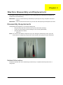
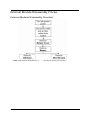
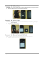
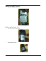
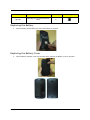
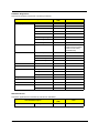
1
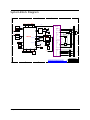
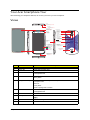
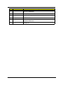
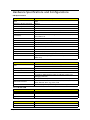
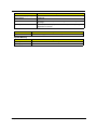
V360 Smartphone Service Guide Service guide files and updates are available on the ACER/CSD web; for more information, please refer to http://gcsd.acer.com.tw/GCSD_Portal/ PRINTED IN TAIWAN Revision History Please refer to the table below for the updates made on the V360 smartphone service guide. Date Chapter Updates II Copyright Copyright © 2011 by Acer Incorporated. All rights reserved. No part of this publication may be reproduced, transmitted, transcribed, stored in a retrieval system, or translated into any language or computer language, in any form or by any means, electronic, mechanical, magnetic, optical, chemical, manual or otherwise, without the prior written permission of Acer Incorporated. Disclaimer The information in this guide is subject to change without notice. Acer Incorporated makes no representations or warranties, either expressed or implied, with respect to the contents hereof and specifically disclaims any warranties of merchantability or fitness for any particular purpose. Any Acer Incorporated software described in this manual is sold or licensed "as is". Should the programs prove defective following their purchase, the buyer (and not Acer Incorporated, its distributor, or its dealer) assumes the entire cost of all necessary servicing, repair, and any incidental or consequential damages resulting from any defect in the software. Acer is a registered trademark of Acer Corporation. Intel is a registered trademark of Intel Corporation. Other brand and product names are trademarks and/or registered trademarks of their respective holders. III Conventions The following conventions are used in this manual: SCREEN MESSAGES Denotes actual messages that appear on screen. NOTE Gives bits and pieces of additional information related to the current topic. WARNING Alerts you to any damage that might result from doing or not doing specific actions. CAUTION Gives precautionary measures to avoid possible hardware or software problems. IMPORTANT Reminds you to do specific actionsm relevant to the accomplishment of procedures. IV Preface Before using this information and the product it supports, please read the following general information. 1. This Service Guide provides you with all technical information relating to the BASIC CONFIGURATION decided for Acer's "global" product offering. To better fit local market requirements and enhance product competitiveness, your regional office MAY have decided to extend the functionality of a machine. These LOCALIZED FEATURES will NOT be covered in this generic service guide. In such cases, please contact your regional offices or the responsible personnel/channel to provide you with further technical details. 2. Please note WHEN ORDERING FRU PARTS, that you should check the most up-to-date information available on your regional web or channel. If, for whatever reason, a part number change is made, it will not be noted in the printed Service Guide. For ACER-AUTHORIZED SERVICE PROVIDERS, your Acer office may have a DIFFERENT part number code to those given in the FRU list of this printed Service Guide. You MUST use the list provided by your regional Acer office to order FRU parts for repair and service of customer machines. V Table of Contents System Specifications 1 Features . . . . . . . . . . . . . . . . . . . . . . . . . . . . . . . . . . . . . . . . . . . . . . . . . . . . . . . . . . . .1 System Block Diagram . . . . . . . . . . . . . . . . . . . . . . . . . . . . . . . . . . . . . . . . . . . . . . . . .3 Your Acer Smartphone Tour . . . . . . . . . . . . . . . . . . . . . . . . . . . . . . . . . . . . . . . . . . . . .4 Views . . . . . . . . . . . . . . . . . . . . . . . . . . . . . . . . . . . . . . . . . . . . . . . . . . . . . . . . . . . . . .4 Hardware Specifications and Configurations . . . . . . . . . . . . . . . . . . . . . . . . . . . . . . . .6 Software Upgrades 8 System Requirements . . . . . . . . . . . . . . . . . . . . . . . . . . . . . . . . . . . . . . . . . . . . . . . . .8 1. Software Upgrading . . . . . . . . . . . . . . . . . . . . . . . . . . . . . . . . . . . . . . . . . . . . . . . . .9 SD Card Upload SOP . . . . . . . . . . . . . . . . . . . . . . . . . . . . . . . . . . . . . . . . . . . . . . . . .22 Acer 22 Code Tool SOP . . . . . . . . . . . . . . . . . . . . . . . . . . . . . . . . . . . . . . . . . . . . . . .25 Machine Disassembly and Replacement 28 Disassembly Requirements . . . . . . . . . . . . . . . . . . . . . . . . . . . . . . . . . . . . . . . . . . . .28 Related Information . . . . . . . . . . . . . . . . . . . . . . . . . . . . . . . . . . . . . . . . . . . . . . .28 General Information . . . . . . . . . . . . . . . . . . . . . . . . . . . . . . . . . . . . . . . . . . . . . . . . . .29 Pre-disassembly Instructions . . . . . . . . . . . . . . . . . . . . . . . . . . . . . . . . . . . . . . .29 Disassembly Process . . . . . . . . . . . . . . . . . . . . . . . . . . . . . . . . . . . . . . . . . . . . .29 External Module Disassembly Process . . . . . . . . . . . . . . . . . . . . . . . . . . . . . . . . . . .30 External Modules Disassembly Flowchart . . . . . . . . . . . . . . . . . . . . . . . . . . . . .30 Removing the Battery Cover . . . . . . . . . . . . . . . . . . . . . . . . . . . . . . . . . . . . . . . .31 Removing the Battery Cover . . . . . . . . . . . . . . . . . . . . . . . . . . . . . . . . . . . . . . . .31 Removing the Memory Card and SIM Card . . . . . . . . . . . . . . . . . . . . . . . . . . . .31 Unscrew the 6 Screws on the Rear Cover . . . . . . . . . . . . . . . . . . . . . . . . . . . . .32 Remove the Low case assemblies . . . . . . . . . . . . . . . . . . . . . . . . . . . . . . . . . . .32 Remove the Main Board . . . . . . . . . . . . . . . . . . . . . . . . . . . . . . . . . . . . . . . . . . .32 Remove the Antenna Sub Board . . . . . . . . . . . . . . . . . . . . . . . . . . . . . . . . . . . .34 Disassembly of Group Photo . . . . . . . . . . . . . . . . . . . . . . . . . . . . . . . . . . . . . . .34 Replacing the Antenna Sub Board . . . . . . . . . . . . . . . . . . . . . . . . . . . . . . . . . . .35 Replacing the Main Board . . . . . . . . . . . . . . . . . . . . . . . . . . . . . . . . . . . . . . . . . .35 Replacing the USB Cable . . . . . . . . . . . . . . . . . . . . . . . . . . . . . . . . . . . . . . . . . .36 Replacing the BTB Connect . . . . . . . . . . . . . . . . . . . . . . . . . . . . . . . . . . . . . . . .37 Replacing the Upper Case . . . . . . . . . . . . . . . . . . . . . . . . . . . . . . . . . . . . . . . . .37 Replacing the Battery . . . . . . . . . . . . . . . . . . . . . . . . . . . . . . . . . . . . . . . . . . . . .38 Replacing the Battery Cover . . . . . . . . . . . . . . . . . . . . . . . . . . . . . . . . . . . . . . . .38 Diagnostics and Troubleshooting 39 Diagnostic Tools and SOP . . . . . . . . . . . . . . . . . . . . . . . . . . . . . . . . . . . . . . . . . . . . .39 User Manual of Service Tool . . . . . . . . . . . . . . . . . . . . . . . . . . . . . . . . . . . . . . . . . . .41 Enter FTM . . . . . . . . . . . . . . . . . . . . . . . . . . . . . . . . . . . . . . . . . . . . . . . . . . . . . .41 Enter FTM test items . . . . . . . . . . . . . . . . . . . . . . . . . . . . . . . . . . . . . . . . . . . . . .41 Touch Panel . . . . . . . . . . . . . . . . . . . . . . . . . . . . . . . . . . . . . . . . . . . . . . . . . . . .42 Keys & Vibrate . . . . . . . . . . . . . . . . . . . . . . . . . . . . . . . . . . . . . . . . . . . . . . . . . .42 Backlight Level . . . . . . . . . . . . . . . . . . . . . . . . . . . . . . . . . . . . . . . . . . . . . . . . . .43 Memory Card . . . . . . . . . . . . . . . . . . . . . . . . . . . . . . . . . . . . . . . . . . . . . . . . . . .43 SIM Detect . . . . . . . . . . . . . . . . . . . . . . . . . . . . . . . . . . . . . . . . . . . . . . . . . . . . .44 WavePlayback . . . . . . . . . . . . . . . . . . . . . . . . . . . . . . . . . . . . . . . . . . . . . . . . . .44 Receiver . . . . . . . . . . . . . . . . . . . . . . . . . . . . . . . . . . . . . . . . . . . . . . . . . . . . . . .45 HeadSet . . . . . . . . . . . . . . . . . . . . . . . . . . . . . . . . . . . . . . . . . . . . . . . . . . . . . . .45 Headset Button . . . . . . . . . . . . . . . . . . . . . . . . . . . . . . . . . . . . . . . . . . . . . . . . . .46 PhoneMic to Headset . . . . . . . . . . . . . . . . . . . . . . . . . . . . . . . . . . . . . . . . . . . . .46 HeadsetMic to Headset . . . . . . . . . . . . . . . . . . . . . . . . . . . . . . . . . . . . . . . . . . . .47 FM Radio . . . . . . . . . . . . . . . . . . . . . . . . . . . . . . . . . . . . . . . . . . . . . . . . . . . . . .47 VI Table of Contents Main Camera . . . . . . . . . . . . . . . . . . . . . . . . . . . . . . . . . . . . . . . . . . . . . . . . . . .48 Sub Camera . . . . . . . . . . . . . . . . . . . . . . . . . . . . . . . . . . . . . . . . . . . . . . . . . . . .48 Gsensor . . . . . . . . . . . . . . . . . . . . . . . . . . . . . . . . . . . . . . . . . . . . . . . . . . . . . . .49 ALS/PS . . . . . . . . . . . . . . . . . . . . . . . . . . . . . . . . . . . . . . . . . . . . . . . . . . . . . . . .49 Bluetooth . . . . . . . . . . . . . . . . . . . . . . . . . . . . . . . . . . . . . . . . . . . . . . . . . . . . . . .50 Wifi . . . . . . . . . . . . . . . . . . . . . . . . . . . . . . . . . . . . . . . . . . . . . . . . . . . . . . . . . . .50 GPS . . . . . . . . . . . . . . . . . . . . . . . . . . . . . . . . . . . . . . . . . . . . . . . . . . . . . . . . . .51 mSensor . . . . . . . . . . . . . . . . . . . . . . . . . . . . . . . . . . . . . . . . . . . . . . . . . . . . . . .51 Thank you!Palette Hardware Diagnostic Tool Introduction . . . . . . . . . . . . . . . . . . . . .52 Introduction . . . . . . . . . . . . . . . . . . . . . . . . . . . . . . . . . . . . . . . . . . . . . . . . . . . . .52 Installation procedure . . . . . . . . . . . . . . . . . . . . . . . . . . . . . . . . . . . . . . . . . . . . .52 Test Item . . . . . . . . . . . . . . . . . . . . . . . . . . . . . . . . . . . . . . . . . . . . . . . . . . . . . . .54 Quit Palette program . . . . . . . . . . . . . . . . . . . . . . . . . . . . . . . . . . . . . . . . . . . . . .58 Serial Number Definition 59 FRU (Field Replaceable Unit) List 60 V360 Smartphone Exploded Diagram . . . . . . . . . . . . . . . . . . . . . . . . . . . . . . . . . . . .61 V360 Smartphone Spare Parts List . . . . . . . . . . . . . . . . . . . . . . . . . . . . . . . . . . . . . .63 Spare Parts List . . . . . . . . . . . . . . . . . . . . . . . . . . . . . . . . . . . . . . . . . . . . . . . . .63 Online Support Information 66 Index 67 VII Chapter 1 System Specifications Features Below is a brief summary of the smartphone’s many features: Form Factor & Dimension • Bar Type, 130 x 67 x 9.9 mm • Android Jelly Bean OS Modes/Bands • HSPA Dual-band 900/2100 • HSDPA up to 7.2Mbps • HSUPA up to 5.76Mbps • GSM Qual-band 850/900/1800/1900 • EDGE class 12/GPRS class 12 Platform • Mediatek MT6577 Memory • 8Gb LPDDR2 + 4GB eMMC Display • 4.5” qHD, Capacitive Multi-Touch (4 pts at least) Camera • Rear 5MP AF (with Flash) + Front VGA Connectivity • BT4.0, WiFi IEEE802.11 b/g/n, WAPI, FM Radio • GPS/AGPS • G-sensor, P + L sensor, E-compass • Micro-USB, 3.5mm HSJ GPS Sensor I/O Chapter 1 1 Keys/Switches • Cap Touch Key for Back/Home/Menu • Side Key: Power key, Volume up/down Battery • 1760mAh Expansion Slot • Micro SD Memory Card • DSDS, 3-color LED Indicator, SRS Others Optional • NFC Accessory • Chapter 1 Headset, Adaptor, USB Cable, Battery 2 System Block Diagram 5 4 3 2 1 D D MCUJTAG 4GBeMMC+ 8GbDDR2 Fcore4JTAG IQ,BSI,BPI JTAG Capacitive TouchPanel JTAG EMI,MSDC0 MT6162 I2C0,EINT GPS PCM,UART3,I2S Backlight Driver G850/G900 GSM Tx S500 MT6620 G1800/1900 AntennaAntenna WiFi/BT MSDC3 Speaker(monodiff) Band1 PA FLASH C Band2 PA FlashLED MT6329 I2C2 CameraIF,I2C1 MainCamera UMTS Tx ClassD/ClassAB (HPRP) MT6577 CameraIF,I2C1 Duplexer Band2 C Band8 PA BC8share Txpath withBC5 Headset(HPLP,HPRP) MT6329 HeadsetEarphone/MIC SubCamera Duplexer Band1 SKY77551/TXM MT6329 LNA MIPIDSI LCM Headset(MCP1,MCN1) BC5andBC8can onlyactiveone inthesametime. Receiver(HSP,HSN) Charger MSDC1 microSD BJT HandsetEarphone/MIC SIM1 MIC(DM_DATAR/DM_CLK) SIM1 (1stMIC) UMTS Rx (AnalogMIC) BC8share Rxpath withBC5 Duplexer Band8 FuelGuage B B USB SIM2 microUSB Battery SIM2 SIM2forGSMonly PWRKEY KCOL KROW HOMEKEY I2C0 EINT Power PowerKey Vol_up Vol_Down GSensor ALS, PSSensor EͲCompass GSM Rx RXSAW filter G850 RXSAW filter G900 RXSAW filter G1800 RXSAW filter G1900 A A Compal Communications, Inc. Title SCHEMATIC, M/B GA-348 (Block Diagram) THIS SHEET OF ENGINEERING DRAWING IS THE PROPRIETARY PROPERTY OF COMPAL COMMUNICATIONS, INC. AND CONTAINS CONFIDENTIAL AND TRADE SECRET INFORMATION . THIS SHEET MAY NOT BE TRANSFERRED FROM THE CUSTODY OF THE COMPETENT DIVISION OF R&D DEPARTMENT EXCEPT AS AUTHORIZED BY COMPAL COMMUNICATIONS,INC. NEITHER THIS SHEET NOR THE INFORMATION CONTAINS MAY BE USED BY OR DISCLOSED TO ANY THIRD PARTY WITHOUT PRIOR WRITTEN CONSENT OF COMPAL COMMUNICATIONS,INC. 5 Chapter 1 4 3 2 Size Document Number Rev Date: CB 601PA9 A2 Thursday, November 29, 2012 Sheet 3 of 24 1 3 Your Acer Smartphone Tour After examining your smartphone features, let us show you around your new smartphone. Views 1. Bezel Plastic/Painting/Soft touch Black 2. Power key Plastic/Painting/Matte Red 3. Receiver mesh Plastic mesh,d0.3/p0.45 Painting/Matte Red 9. Speaker mesh Stainless/etching 10. Circle brush/PVD Meet Black 4. TP frame Plastic/PC Glossy Black 11. Camera ring Aluminium Diamond cut/陽極髮絲紋 12. Flash lens Transparent plastic 13. Camera lens Glass/back printing transparent area 8. Vol.key Plastic/NCVM 黑鉻色 14. Nameplate/metal Refer to Acer-C6 5. TP / glass / back print White (same as the Battery cover color) Transparent area Mirror ink Smoky black Sensor opening refer to criteria 15. Battery cover Plastic/Painting/soft touch Black 3D pattern/recess0.1mm 16. dts logo/Painting Cool gray 7C 7. Pattern area 6. Receiver mesh Plastic mesh,d0.3/p0.45 Painting/Matte Red No. Item Description 1 Bezel Plastic/Painting/Soft touch Black 2 Power key Plastic/Painting/Matte Red 3 Receiver mesh Plastic mesh,d0.3/p0.45 Painting/Matte Red 4 TP frame Plastic/PC Glossy Black 5 TP / glass / back print White (same as the Battery cover color) Transparent area Mirror ink Smoky black Sensor opening refer to criteria 6 Receiver mesh Plastic mesh,d0.3/p0.45 Painting/Matte Red 7 Pattern area 8 Vol.key 9 Speaker mesh Stainless/etching 10 Circle brush/PVD Meet Black Plastic/NCVM 黑鉻色 Chapter 1 4 No. 11 Item Camera ring Description Aluminium Diamond cut/ 陽極髮絲紋 12 Flash lens 13 Camera lens Transparent plastic Glass/back printing transparent area 14 Nameplate/metal Refer to Acer-C6 15 Battery cover Plastic/Painting/soft touch Black 16 dts logo/Painting 3D pattern/recess0.1mm Chapter 1 Cool gray 7C 5 Hardware Specifications and Configurations HW Specifications Item Specification Band Dual-Band (Band 1 & Band 8) WCDMA ; Quad-band EDGE/ GPRS/ GSM Application/ Modem Processor MT6577 Power Management MT6329A RF Transceiver MT6162 Memory 8Gb LPDDR2 + 4GB eMMC MCP memory Expansion Flash Card Slot Micro SD Connectivity Bluetooth 3.0 with EDR, WiFi b/g, FM radio, 3.5mm Audio jack, microUSB2.0 HS GPS standalone and assisted Camera 5M AF camera, with flash light; VGA camera LCM 4.5” qHD (540 x 960) 16.7M colors TFT Touch Panel Capacitive touch Sensors G-Sensor, E-Compass, P&L Sensor Indication LED Yes Keypad Hardware keys: power/standby key, volume up/ down Battery 176mAH, Removable battery Dual SIM Optional Dual standby Single Talk HW reserved (one for 3G & one for GSM voice) Processor Item Specification 1 GHz dual-core Cortex-A9 MCU core for applications/MMI CPU 520 MHz ARM1176 + 260 MHz DSP modem cores CPU Package 537 balls Core Logic Cortex-A9 Modem ARM1176 UART 4 x UART to 3Mbps (EDR) for GPS, BT, FM-RDS, modem and debugging interfaces SDIO 4 x SDIO interfaces (SD/MMC/MS & MSPro, eMMC v4.4) Audio/video decoders MPEG4, H.264, H.263, VP8 Codecs, MP3, AAC, AAC+, eAAC+, AMR, WB-AMR, MIDI, Ogg Vorbis, PCM USIM Dual SIM (Single Talk), Built-in support for dual-voltage USIM 4.5” a-Si TFT-LCD Item Specification Display resolution (pixels) 960(V)x540(H) Supported Colors 16.7M Type Transmissive Battery Item Specification Vendor APACK Rating 3.75V Chapter 1 6 Item Specification Maximum Charging Voltage 4.35V Pack capacity 1300 mAh Talk time Talk time 3G: 4 hours dependent on usage / 2G: 5 hours dependent on usage Standby 300 hours (WDCDMA) dependent on network, 300 hours (GSM) dependent on network. Camera Item Type Specification • Built-in 5 megapixel Auto-Focus camera, up to 2592 x 1944 resolution System Memory Item Specification Memory embedded 8Gb LPDDR2 + 4GB eMMC MCP memory Memory expansion Micro SD Card slot Chapter 1 7 Chapter 2 Software Upgrades System Requirements • • • • Microsoft® Windows XP or above P4, 2.8G and Ram 1G DDR or above Latest version of EUU (End-user Upgrade Utility / EUU_xxx.msi) Tool: USB Cable NOTE: Please make sure mobile battery power is over 50% before execute EUU. NOTE: Please disable Anti-Virus software if EUU is blocked by it. NOTE: The minimum requirement of the OS disk is 1 GB space Chapter 2 8 1. Software Upgrading Acer C10 upgrading software program applies SP_Flash_Tool. Refer to the following for its specific configurations and download steps 1.1 Hardware configurations and parts requirements Chapter 2 Item Equipment Standard configuration Qty 1 PC Win2000/WinXP/Win7/USB2.0 1 2 Download cable 1 3 Battery 1 4 Download Tool 1 9 1.2 Operation steps 1.2.1 Install the upgrading tool Step 1. Open the SP_Flash_Tool_exe__v3.1236.0.zip and decompress it to SP_Flash_Tool_exe__v3.1232.0.36 folder. Step 2. Enter the SP_Flash_Tool__v3.1232.0.sn36 folder. Chapter 2 10 Step 3. Click "Flash_tool.exe" icon to open the Flash Tool Chapter 2 11 1.2.2 Install the download cable driver Step 1. Connect the USB cable after removing the cell phone battery and insert it into a PC, enter the device manager, the MTK USB Port will be viewed. Step 2. Right-click to update the driver software. Chapter 2 12 Step 3. Click to browse the driver software on the PC. Step 4. Select the USB VCOM Drive folder, select SP_Drivers_V1.4 and click OK. Chapter 2 13 Step 5. The PC will enter the following interface after clicking OK, Click Next. Step 6. The PC will enter the following interface after clicking OK (Safety Tips), select keep installing this driver again to install it. Chapter 2 14 Step 7. The PC will enter the interface "Install the driver". Step 8. The installation is completed. Chapter 2 15 1.2.3 Upgrading steps Step 1. Return to SP_Flash_Tool and remove the USB cable from the PC. Chapter 2 16 Step 2. Press Scatter-loading. Step 3. The following folder will pop up, select the MT6577_emmc_AA66_XXXXX. txt in image. Chapter 2 17 Step 3. The following folder will pop up. Chapter 2 18 Step 4. Press Firmware->Upgrade and connect the cell phone (with its battery installed properly) to a PC via a USB cable for upgrading. Chapter 2 19 Step 4. The following interface will pop up to prompt that the upgrading is completed after the above two interfaces appear. Chapter 2 20 Chapter 2 21 SD Card Upload SOP 1. Copy the upgrade file into root path of SD card, and then insert into phone Note. Make sure the SD card has enough free space which should be double than upgrade package, for example, 200M upgrade file needs 400M free space. 2. Keep press Vol-UP and power button for 2 seconds and enter into Select Boot Mode UI as the illustration P1. P1 3. When see the P1 UI, then press Vol-up to move the cursor to “Recovery Mode”and press Vol-down to select, then the system will migrate into illustration P2 P2 Chapter 2 22 4. At the status of P2, press power key, then system migrate into recovery menu as below illustration P3 P3 5. At the status of P3, press Vol-up to move the option of “apply update from external sdcard”. 6. Press Vol-down to select “apply update from external sdcard”, then system migrates into the below illustration P4 P4 Chapter 2 23 7. At the status of P4, press Vol-up to move the cursor on the “upgrade_Acer_AV051_V360_XXXXX_XX-XXX.zip” then press Vol_down to select, then system start to upgrade as illustration P6 P5 8. When the upgrade is done, then migrate into recovery menu and show “Install from sdcard complete” on screen as below illustration P6 P6 9. At the status of P6, “reboot system now” has been selected by default and then press Vol-down to reboot phone, then complete the upgrade work 10. Frequent reason of upgrade fail and action (1) Apply a fault SD card file package (for example other phone package) Action: you should select appropriate upgrade file package (2) Fail to copy the upgrade package into SD by interfere of anti-virus tool or original upgrade package is corrupted Action: delete the corrupted file on SD card and copy from an appropriate PC resource or change SD card to use Chapter 2 24 Acer 22 Code Tool SOP 1. Pre-condition A: Please make sure the USB driver has been installed into your computer.Need to execute Install.bat in the USB driver folder B: The OS of your computer should be Windows XP SP3 above or Win 7 version. C: The SN_Write_tool_exe_v2.1232.0 should be ready in your computer. User could install setup.exe in the folder of SN_Write_tool_exe_v2.1232.0 until the program setup complete. 2. Install SOP A. Make sure the mobile phone does not connect your computer, double click Write_SNID.exe to launch the Tool B. If the screen shows as follow, it means that you need install SN_Write_tool_exe_v2.1232.0 first. B: Enter tool UI as follow Chapter 2 25 C: Select the Modem database and AP database. Please make sure the Modem/AP database (Normally in the SW version img folder) you are going to select is the same as the one in your mobile phone, OR you wont write SNID successfully For example: if your mobile phone has been written SW Version Acer_AV051_V360_1.000.00_GC_Gen1 Then your selected Modem Database should be the folder of Acer_AV051_V360_1.000.00_GC_Gen1 Select the database file as follow illustration D: Click the Start button to process the Write Acer SNID E: If the screen shows need add new component (Acer preloader Vcom; Acer USB Vcom), user should select auto install software(Recommend) and forward the driver until the install complete Chapter 2 26 F: Keep install if popup below windows until the driver install OK G: If the driver install is OK, please launch Tool again with take the battery power off->on, and execute the above procedure to load modem database and connect mobile phone H: The tool will show COM Port searching and Preloader handshake Then insert the USB cable into your mobile phone which should be power-off and the battery should be in the phone. I: Input the Acer 22 Number into Dialog Windows J: Proceeding Write SNID until the finish. Chapter 2 27 Chapter 3 Machine Disassembly and Replacement This chapter contains step-by-step procedures on how to disassemble and reassemble the smartphone for maintenance and troubleshooting. IMPORTANT: The use of metal tools during disassembly may damage the casing. Use plastic tools where possible. IMPORTANT: Cover the work area with a clean, dry, lint-free cloth before placing the smartphone face down. Disassembly Requirements To disassemble the smartphone, you need the following tools: • Wrist grounding strap and conductive mat to prevent electrostatic discharge • A clean, dry, lint free cloth to prevent damage to the LCD during disassembly • Tweezers (plastic and metal) • Plastic Pry NOTE: The screws for the different components vary in size. During the disassembly process, group the screws with the corresponding components to avoid mismatch when putting back the components. Related Information The product previews seen in the disassembly procedures may not represent the final product color or configuration. Chapter 3 28 General Information Pre-disassembly Instructions IMPORTANT: Before proceeding with the disassembly procedure, make sure that you do the following: 1. Turn off the power to the system. 2. Unplug the USB adapter and all other cables from the system. 3. Cover the work area with a clean, dry, lint-free cloth to protect the LCD panel. 4. Place the system on a flat, stable surface. Disassembly Process The disassembly process is divided into the following sections: • External components disassembly • Main unit disassembly The flowcharts provided in the succeeding disassembly sections illustrate the entire disassembly sequence. Observe the order of the sequence to avoid damage to any of the hardware components. Main Screw List Screw Quantity Part Number TORX MA1.6 Y L2.8 DARK AISI1018 30037 6 3500000069W Chapter 3 29 External Module Disassembly Process External Modules Disassembly Flowchart NOTE: Items enclosed with broken lines (— - - —) are optional and may not be present. Chapter 3 30 Removing the Battery Cover IMPORTANT: Cover the work area with a clean, dry, Lint-free cloth before placing the smartphone face down. 1. Remove the Battery Cover from the side as show as picture below. Removing the Battery Cover IMPORTANT: The Battery is locked in place ; do not force the Battery out of the battery bay before open in locking mechanism. 1. Gently pull down to release the Battery. Removing the Memory Card and SIM Card NOTE: The Memory Card and SIM Card are both optional items and may not be present. 1. Gently push and pull out the SIM Card and the Memory Card. Chapter 3 31 Unscrew the 6 Screws on the Rear Cover Step Screw Quantity Upp Assy TORX MA1.6 Y L2.8 DARK AISI1018 30037 6 Screw Type Remove the Low case assemblies Remove the Main Board 1. Loosen the cable head on the main board. Chapter 3 32 2. Uncover the BTB on the Main Board. 3. Uncover the Main Board. 4. Loosen the ZIF on the main board. 5. Remove the main board Chapter 3 33 Remove the Antenna Sub Board 1. Loosen the ZIP on the sub board. 2. Loosen the cable head on the sub board 3. Uncover the BTB on the sub board. Disassembly of Group Photo Chapter 3 34 Replacing the Antenna Sub Board 1. Assemble back the ZIP on the sub board. 2. Contact the cable head on the sub board. 3. Cover the BTB on the sub board. Replacing the Main Board 1. Assemble the ZIF on the main board. Chapter 3 35 2. Assemble back the Main board on the Upper cover. Replacing the USB Cable 1. Assemble back the USB cable Chapter 3 36 Replacing the BTB Connect 1. Assemble back the BTB Connect. Replacing the Upper Case 1. Assemble the Low case and replacing. 2. Insert the 6 screw as show. Chapter 3 37 Step Screw Quantity Upp Assy TORX MA1.6 Y L2.8 DARK AISI1018 30037 6 Screw Type Replacing the Battery 1. Insert the battery into the Battery bay and lock the Battery in the place. Replacing the Battery Cover 1. Insert the Bottom of Battery Cover into the smart phone and push the Battery cover into the place. Chapter 3 38 Chapter 4 Diagnostics and Troubleshooting Diagnostic Tools and SOP This document is intended to evaluate requirements of CCI Service Engineering (CSE), a application which facilitates repairing for after service. Definitions, Acronyms, and Abbreviations Term Definition SHV Software/Hardware Version TFT Time to Failure Timer FBI Failure Bye Identifiers EFEM Engineer test mode DOM Date Of Manufacture SN Serial Number Subsidy Lock Interface for the application layer to determine whether ME is permitted operate with currently inserted SIM. Delivery Item Name/Description Whole package customized by CCI CCI to develop full and standalone package Required (Y/N) Note Required (Y/N) Note Y Functionality Handset Specific Data Retrieve or update handset specific information Item Name/Description ReadIMEI Read IMEI number Y ReadSWVersion Read SW Version Y ReadDOM Read DOM Y ReadFBI Read FBI Y IncreaseFBI Value of FBI increase 1 Y ResetFBI Reset FBI to 0 Y ReadSN Read SN Y ReadBluetoothMacAddress Read Bluetooth MAC address Y Chapter 4 39 Hardware Diagnostics Test items of hardware components or accessory interfaces Required (Y/N) Item Name/Description Main Display LCM- White Y LCM -Black Y LCM -Red Y LCM -Green Y LCM -Blue Y LCM Back Light-High Y LCM Back Light-Med Y LCM Back Light-Low Y HID Keypad Y Audio Test tone to speaker Y MIC test Y Test tone to earphone Y Record from earphone Y Vibrator Vibrator Y BT Turn on/off Y Indicator LED light color-Red Y LED light color-Green Y LED light color-White Y Storage SD card detection Y Battery Status Read battery status Y Camera Preview Y Sensor G-Sensor Y E-Compass Y Note Menu/Search/Back/Volume Up/Volume Down/Camera (Power & Home test by default behavior) Voltage & temperature Stand-alone tool Companion applications that launched by CSE and run standalone Required (Y/N) Item Name/Description DM Tool Chapter 4 Flashing Note Y 40 User Manual of Service Tool Enter FTM On Shutdown state just press VolumeDown + Power button, we can enter into the FTM., On the right is the FTM main interface, there are four options: Item Test: the FTM test items Clear Test Report: Clear test results Version: version information ShutDown: Shutdown PS: under the FTM, mainly through the volume up and down keys to operate on key confirmation key, the next key is to select key. Enter FTM test items On the right is the main menu of FTM test item. To do a test, as long as you use the Down key select to one item, and then press the UP button to confirm the item. Selection On the Back item, you can return to the previous menu level Chapter 4 41 Touch Panel After entering this test item, use your fingers to operate the screen, draw a straight line between the two red lines, horizontal 10 lines vertical 6 lines, and then automatically end the test. Keys & Vibrate Enter the Keys & Vibrate item, in turn, press the volume key, volume down key,power button, followed by the phone vibrate, then the test ends automatically and return to the main menu. Chapter 4 42 Backlight Level After entering the test item, there will be two sub-measure items Show Test Images: enter the submeasure and continuously press the button, check the display of default 8 photos is normal. Change Contrast: This sub-test item test LCD shade. Election to the measured item, and then press 5 times on key to adjust the brightness of the screen to complete the test. Memory Card The system will automatically detect the SD, and then automatically complete the test but if parked in the right, just Format emmc FAT, you can continue to complete the test. PS: The SD card is inserted before the test Chapter 4 43 SIM Detect Insert two SIM cards, the system automatically detects these two cards, and then check the detection results, select "Test Pass" or the "Test Fail" WavePlayback In turn test the left and right channels of the Speaker, to see whether the music can output from both Speaker. Chapter 4 44 Receiver Check whether the music play normal on the receiver. HeadSet Insert the headset, select "test headset", and then the music output from the left and right channels, respectively. Chapter 4 45 Headset Button Plug in your headphones before enter the test item , click the headset hook button to complete the test PhoneMic to Headset In turn to select Mic1 Mic2, and then speak to Mic1 or Mic2, check whether the sound output from the headset. Chapter 4 46 HeadsetMic to Headset Speak to Headset Mic,then check whether the Sound output from the headset. FM Radio Plug into Headphones and test the FM can receive the 100MH and 107.1MHz broadcast. Chapter 4 47 Main Camera Put the phone on the tooling, select "Preview / Capture / Strobe" to test the Camera. Previously Move the system to test focus function. Then press the Down key to test flash (record number of flash & n) and then Up key to take picture and Down key to return. Finally, based on the number of flash, select the "Test Pass with & n" Sub Camera Select the Preview / Capture, press on Up key for self-timer, and then press Down key to return. Chapter 4 48 Gsensor Put the phone on the tooling, press the key to enter the test item, wait until the phone initialization is complete. Then turn the tooling and make six faces of the tooling parallel to the ground Respectively. ALS/PS This item need to test the ALS uncover, and PS Uncover and Cover process. Put the phone into the tooling, start the test item. Step 1: the state of the phone is uncover, select the "Test Light Sensor" Step 2: the state of the phone is uncover, select "Test P sensor" Step 3: the phone is in the state of the cover, again select the "Test P Sensor" Chapter 4 49 Bluetooth Into the test item, after initialization into the test instrument. Use computer software to control the instrument to test. Finally, according to the test results to select the "pass or fail" Wifi Into the test items, the system will automatically find the hotspot called "TestAP" no password, then automatically end. Chapter 4 50 GPS Put the phone on the tooling,enter the test item, and then the phone is searching for satellites. mSensor Into the test item, and then hold the phone, draw an "8" to calibrate. Put the phone on the tooling with a northsouth direction placed, and finally select "Test for North" to complete the test. Chapter 4 51 Thank you!Palette Hardware Diagnostic Tool Introduction Introduction Palette is a service tool which developed by Acer software team. This is a simple test tool to supply front end operators shop or collection points for simple diagnostic testing. Installation procedure 1. Install "Acer_Palette_2.000.00_GEN.msi" at PC/NB site. 2. Execute "Palette_Main". Select "HW Diagnostic". Chapter 4 52 3. Please fill in necessary customer's data to the columns then click "Confirm". 4. At Android device, ensure micro SD card is inserted. Please enable "USB Debugging" option (tap Menu Settings Applications Development, click "USB Debugging") then contact to PC via USB cable. Chapter 4 53 5. Now HW Diagnostic status screen pop-up. Test Item 1. Diagnostic Test Menu There are 7 test items can be used in Diagnostic test. 2. LCM Tap the screen to change difference colors to check LCD. Confirm test is passed if no errors. Chapter 4 54 3. Touch Draw 4 lines on screen. Confirm test is passed if no errors. 4. SD Test SD card read/write. Select "Close" if no errors. 5. Button Press each buttons to verify the functions. Tap "Exit" to quit the test. Confirm test is passed if no errors. Chapter 4 55 6. Vibrator Tap "Test" to verify vibration function. Confirm test is passed if no errors. Chapter 4 56 7. Camera Check the camera screen is good. Press "Back" button to quit test. Confirm test is passed if no errors. 8. Audio This test verifies sound playing/recording on Speaker, Receiver and Earphone. Press "Back" button to quit the test. Confirm test is passed if no errors. 9. Tap "Exit" to quit test program on Android device. Chapter 4 57 10. Click "Finish" to complete simple diagnostic testing. Quit Palette program Tap "Exit" to close the program. Chapter 4 58 Chapter 5 Serial Number Definition The following information describes the serial number details available on the Acer product sticker. To view the serial number, remove the Back Cover and Battery (see "Disassembly Process" on page 16) as shown below: The following describes the information on the product sticker: Acer 22 Barcode Follows Code 128 standard—refer to http://www.adams1.com/pub/russadam/128code.html Acer_22_Code_SN PPPPPPPPPPYWWSSSSSMMVV Code Description PPPPPPPPPP Acer Part Number YWW 3 digit numeric year and week code SSSSS 5character unique hexadecimal code by manufacturer base and reseteachweek (0-9, A, B, C, D, E, F 16 code) MM Manufacturer code VV English version code Acer SNID YWWddddddMM Code Description YWW 3 digit numeric year and week code (as above) dddddd 6 digit unique number derived from Acer 22 Code SN (SSSSS) Transfer Rule: S1S2S3S4S5 dddddd = S1 * 164 + S2 * 163 + S3 * 162 + S4 * 161 + S5 For example: 001FD = 000509 (1 * 162 + 15 * 161 + 13) MM Chapter 5 Manufacturer code (as above) 59 Chapter 6 FRU (Field Replaceable Unit) List This chapter gives you the FRU (Field Replaceable Unit) listing in global configurations of the F900 smartphone. Refer to this chapter whenever ordering for parts to repair or for RMA (Return Merchandise Authorization). Please note that WHEN ORDERING FRU PARTS, you should check the most up-to-date information available on your regional web or channel. If for whatever reasons a part number change is made, it will not be noted on the printed Service Guide. For ACER AUTHORIZED SERVICE PROVIDERS, your Acer office may have a DIFFERENT part number code from those given in the FRU list of this printed Service Guide. You MUST use the local FRU list provided by your regional Acer office to order FRU parts for repair and service of customer machines. NOTE: To scrap or to return the defective parts, you should follow the local government ordinance or regulations on how to dispose it properly, or follow the rules set by your regional Acer office on how to return it. Chapter 6 60 V360 Smartphone Exploded Diagram PART NAME FPC RF CABLE CAMERA 5M MB-ASSY DUAL WATERPROOF LABEL ANTENNA BOARD SUB BOARD LCD MODULE BLACK(LCD.TP.UPPER) LOW-ASSY DUAL BATTERY COVER BLACK DUAL BATTERY COVER BLACK SINGLE NFC MAIN ANTENNA VOLUME KEY POWER KEY BLACK Chapter 6 DESCRIPTION ACER PART NO. AA66 GF-256 REV:1.0 MB/SB FPC 50.HBPH1.001 WFL2-2HF6-04K2TV-A HRS 50.HBPH1.002 CAMERA CP56A548 ABILITY KR.05M0A.001 AA66 MB+SPONGE+GASKET (Non NFC) HB.70511.00V AV30 WATERPROOF £p5mm CROSS 47.H460W.005 AA66 SB(ANTENNA)+SPONGE 55.HBPH1.001 AA66 SB(AUDIO) 55.HBPH1.002 AA66 UPPASY(BLACK)+TP+LCM 6M.HBPH1.001 AA66 LOWASY(BLACK)+RING(SIL) (Non NFC) 60.HBPH1.001 AA66 BATCOV(BLACK)+SPONGE (Non NFC) 60.HBPH1.002 AA67 BATCOV(BLACK)+SPONGE (NFC) 60.HBRH1.002 I-ANTENNA AA66 MAIN_PENTA 60.HBPH1.004 BUTTON P+R BLACK VOLUME KEY 2KEY 42.HBPH1.001 P+R BLACK POWER 1KEY 42.HBQH1.001 61 PART NAME RECEIVER ACER PART NO. TBD AA66 RECEIVER MESH TBD SPEAKER 1 XHS160901SW45P42-02 HAOSHENG 23.HBPH1.001 SPEAKER 2 SO181238LD01 GETTOP 23.HBPH1.002 KAPTON ZIF CONNECTOR 47.HBPH1.001 RUBBER SI VGA 47.HBPH1.002 RUBBER SI P-SENSOR 47.HBPH1.003 TORX MA1.6 Y L2.8 DARK AISI1018 30037 86.HBPH1.001 RECEIVER MESH KAPTON RUBBER VGA RUBBER P-SENSOR SCREW Chapter 6 DESCRIPTION AA66 RECEIVER 62 V360 Smartphone Spare Parts List Spare Parts List Photo Chapter 6 DESCRIPTION ACER P/N RF CABLE 50.HBPH1.002 USB CABEL BLACK HC.70211.01F FPC 50.HBPH1.001 EARPHONE HC.00111.002 BATTERY CHINA KT.0010S.006 BATTERY MAIN KT.0010S.004 BATTERY FRENCH KT.0010S.005 ADAPTER CHINA BLACK KP.0050B.003 ADAPTER UK KP.0050P.002 ADAPTER US KP.0050P.003 ADAPTER EU KP.0050P.001 MB-ASSY DUAL HB.70511.00V MB-ASSY SINGLE NFC HB.70511.00W WATERPROOF LABEL 47.H460W.005 ANTENNA BOARD 55.HBPH1.001 SUB BOARD 55.HBPH1.002 LCD MODULE BLACK(LCD.TP.UPPER) 6M.HBPH1.001 LCD MODULE WHITE(LCD.TP.UPPER) 6M.HBQH1.00 63 Photo Chapter 6 DESCRIPTION ACER P/N LOW-ASSY DUAL 60.HBPH1.001 LOW-ASSY SINGLE NFC 60.HBRH1.001 BATTERY COVER BLACK DUAL 60.HBPH1.002 BATTERY COVER WHITE SINGLE 60.HBSH1.001 BATTERY COVER WHITE DUAL 60.HBQH1.001 BATTERY COVER BLACK SINGLE 60.HBRH1.002 RECEIVER 60.HBPH1.003 MAIN ANTENNA 60.HBPH1.004 VOLUME KEY 42.HBPH1.001 POWER KEY RED 42.HBPH1.002 POWER KEY BLACK 42.HBQH1.001 SPEAKER 1 23.HBPH1.001 SPEAKER 2 23.HBPH1.002 KAPTON 47.HBPH1.001 RUBBER VGA 47.HBPH1.002 64 Photo Chapter 6 DESCRIPTION ACER P/N RUBBER P-SENSOR 47.HBPH1.003 CAMERA 5M KR.05M0A.001 SCREW 86.HBPH1.001 65 Appendix A Online Support Information This section describes online technical support services available to help you repair your Acer device. If you are a distributor, dealer, ASP or TPM, please refer your technical queries to your local Acer branch office. Acer Branch Offices and Regional Business Units may access our website. However some information sources will require a user i.d. and password. These can be obtained directly from Acer CSD Taiwan. Acer's Website offers you convenient and valuable support resources whenever you need them. In the Technical Information section you can download information on all of Acer's products including: • Service guides for all models • User's manuals • Training materials • Software utilities • Spare parts lists • TABs (Technical Announcement Bulletin) For these purposes, we have included an Acrobat File to facilitate the problem-free downloading of our technical material. Also contained on this website are: • Detailed information on Acer's International Traveler's Warranty (ITW) • Returned material authorization procedures • An overview of all the support services we offer, accompanied by a list of telephone, fax and email contacts for all your technical queries We are always looking for ways to optimize and improve our services, so if you have any suggestions or comments, please do not hesitate to communicate these to us. Appendix A 66 Index Numerics SIM Card Removing 6 Screws on the Rear Cover Unscrew 31 System 32 Block Diagram A 3 U Antenna Sub Board Upper Case Remove 34 Replacing 35 Replacing B Replacing 36 V Battery Replacing 37 USB Cable 38 Views Battery Cover 4 Removing 31 Replacing 38 BTB Connect Replacing 37 C Conventions IV E External Module Disassembly Flowchart 30 F FRU (Field Replaceable Unit) List 60 G Group Photo Disassembly 34 L Low case assemblies Remove 32 M Main Board Remove 32 Replacing 35 Memory Card Removing 31 S Index 67