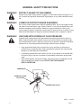
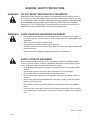
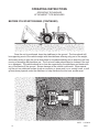
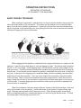
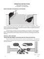
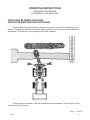
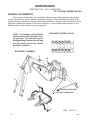
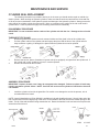
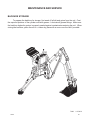
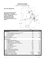
1
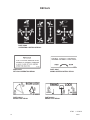
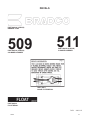
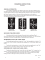
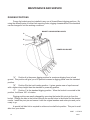
OPERATOR’S MANUAL
509 & 511 POWER BACKHOES
SERIAL NUMBER: ___________________
MODEL NUMBER: ___________________
800-456-7100 I www.paladinattachments.com
Manual Number: OM575
Part Number: 75475
Rev. 6
503 Gay Street, Delhi, IA 52223, United States of America Copyright ©
7483
10-23-12-8
TABLE OF CONTENTS
POWER BACKHOES
PREFACE.................................................................................................................................3
SAFETY PRECAUTIONS
SAFETY STATEMENTS.................................................................................................5
GENERAL SAFETY PRECAUTIONS......................................................................... 5-7
EQUIPMENT SAFETY PRECAUTIONS.........................................................................8
DECALS
DECAL PLACEMENT.....................................................................................................9
DECALS.................................................................................................................. 10-13
PRE-OPERATION
GENERAL INFORMATION...........................................................................................14
PREPARING THE VEHICLE.........................................................................................14
BACKHOE BUCKET OPTIONS....................................................................................14
NOMENCLATURE........................................................................................................15
OPERATING INSTRUCTIONS
GENERAL INFORMATION...........................................................................................16
CONTROLS..................................................................................................................16
BEFORE YOU START DIGGING........................................................................... 17-18
BASIC DIGGING TECHNIQUES............................................................................ 19-20
SPECIAL APPLICATIONS...................................................................................... 20-24
TRANSPORTING.........................................................................................................25
LUBRICATION
LUBRICATION SYMBOLS AND DIAGRAM........................................................... 26-27
MAINTENANCE AND SERVICE
GENERAL INFORMATION...........................................................................................28
EVERY 8 HOURS.........................................................................................................28
EVERY 40 HOURS.......................................................................................................28
CONTROL VALVE........................................................................................................29
REPLACING BUCKET TOOTH POINTS......................................................................29
CHANGING BUCKETS.................................................................................................29
BUCKET DIGGING POSITIONS..................................................................................30
HOSE ROUTING.................................................................................................... 31-32
CYLINDER SEAL REPLACEMENT........................................................................ 33-34
STORAGE....................................................................................................................35
TROUBLESHOOTING...................................................................................................... 36-38
SPECIFICATIONS
BOLT TORQUE SPECIFICATIONS..............................................................................39
BACKHOE SPECIFICATIONS......................................................................................40
CYLINDER AND BUCKET SPECIFICATIONS.............................................................41
PRE-DELIVERY CHECK LIST................................................................................................43
LIMITED WARRANTY............................................................................................................45
6893
75475
8-23-11-3
1
THIS PAGE
IS INTENTIONALLY
BLANK
2
75475
PREFACE
GENERAL COMMENTS
Congratulations on the purchase of your new BRADCO product! This product was carefully designed and manufactured to give you many years of dependable service. Only minor
maintenance (such as cleaning and lubricating) is required to keep it in top working condition.
Be sure to observe all maintenance procedures and safety precautions in this manual and on
any safety decals located on the product and on any equipment on which the attachment is
mounted.
This manual has been designed to help you do a better, safer job. Read this manual
carefully and become familiar with its contents.
WARNING! Never let anyone operate this unit without reading the "Safety Precautions"
and "Operating Instructions" sections of this manual.
Always choose hard, level ground to park the vehicle on and set the brake
so the unit cannot roll.
Unless noted otherwise, right and left sides are determined from the operator’s control
position when facing the attachment.
NOTE: The illustrations and data used in this manual were current (according to the
information available to us) at the time of printing, however, we reserve the right to redesign and change the attachment as may be necessary without notification.
BEFORE OPERATION
The primary responsibility for safety with this equipment falls to the operator. Make
sure the equipment is operated only by trained individuals that have read and understand this
manual. If there is any portion of this manual or function you do not understand, contact your
local authorized dealer or the manufacturer.
SAFETY ALERT SYMBOL
This is the "Safety Alert Symbol" used by this industry. This symbol is used to
warn of possible injury. Be sure to read all warnings carefully. They are included
for your safety and for the safety of others working with you.
SERVICE
When servicing your product, remember to use only manufacturer replacement parts.
Substitute parts may not meet the standards required for safe, dependable operation.
To facilitate parts ordering, record the model and serial number of your unit in the space
provided on the cover of this manual. This information may be obtained from the identification
plate located on the product.
The parts department needs this information to ensure that you receive the correct parts
for your specific model.
10344
75475
8-20-05
3
THIS PAGE
IS INTENTIONALLY
BLANK
4
75475
SAFETY STATEMENTS
THIS SYMBOL BY ITSELF OR WITH A WARNING WORD THROUGHOUT THIS MANUAL IS USED TO CALL YOUR ATTENTION TO INSTRUCTIONS INVOLVING YOUR
PERSONAL SAFETY OR THE SAFETY OF OTHERS. FAILURE TO FOLLOW THESE
INSTRUCTIONS CAN RESULT IN INJURY OR DEATH.
DANGER
THIS SIGNAL WORD IS USED WHERE SERIOUS INJURY OR DEATH
WILL RESULT IF THE INSTRUCTIONS ARE NOT FOLLOWED PROPERLY.
WARNING
THIS SIGNAL WORD IS USED WHERE SERIOUS INJURY OR DEATH
COULD RESULT IF THE INSTRUCTIONS ARE NOT FOLLOWED PROPERLY.
CAUTION
THIS SIGNAL WORD IS USED WHERE MINOR INJURY COULD RESULT IF
THE INSTRUCTIONS ARE NOT FOLLOWED PROPERLY.
NOTICE
NOTICE INDICATES A PROPERTY DAMAGE MESSAGE.
GENERAL SAFETY PRECAUTIONS
WARNING! READ MANUAL PRIOR TO INSTALLATION
Improper installation, operation, or maintenance of this equipment could result in
serious injury or death. Operators and maintenance personnel should read this manual, as well as all manuals related to this equipment and the prime mover thoroughly
before beginning installation, operation, or maintenance. FOLLOW ALL SAFETY
INSTRUCTIONS IN THIS MANUAL AND THE PRIME MOVER’S MANUAL(S).
READ AND UNDERSTAND ALL SAFETY STATEMENTS
Read all safety decals and safety statements in all manuals prior to operating or
working on this equipment. Know and obey all OSHA regulations, local laws, and
other professional guidelines for your operation. Know and follow good work
practices when assembling, maintaining, repairing, mounting, removing, or operating
this equipment.
KNOW YOUR EQUIPMENT
Know your equipment’s capabilities, dimensions, and operations before operating.
Visually inspect your equipment before you start, and never operate equipment that
is not in proper working order with all safety devices intact. Check all hardware to
ensure it is tight. Make certain that all locking pins, latches, and connection devices
are properly installed and secured. Remove and replace any damaged, fatigued, or
excessively worn parts. Make certain all safety decals are in place and are legible.
Keep decals clean, and replace them if they become worn or hard to read.
10338
75475
8-16-05
5
GENERAL SAFETY PRECAUTIONS
WARNING! PROTECT AGAINST FLYING DEBRIS
Always wear proper safety glasses, goggles, or a face shield when driving pins in or
out, or when any operation causes dust, flying debris, or any other hazardous material.
WARNING! LOWER OR SUPPORT RAISED EQUIPMENT
Do not work under raised booms without supporting them. Do not use support material made of concrete blocks, logs, buckets, barrels, or any other material that could
suddenly collapse or shift positions. Make sure support material is solid, not decayed, warped, twisted, or tapered. Lower booms to ground level or on blocks. Lower
booms and attachments to the ground before leaving the cab or operator’s station.
WARNING! USE CARE WITH HYDRAULIC FLUID PRESSURE
Hydraulic fluid under pressure can penetrate the skin and cause serious injury or
death. Hydraulic leaks under pressure may not be visible. Before connecting or disconnecting hydraulic hoses, read your prime mover’s operator’s manual for detailed
instructions on connecting and disconnecting hydraulic hoses or fittings.
• Keep unprotected body parts, such as face, eyes, and arms as far away as
possible from a suspected leak. Flesh injected with hydraulic fluid may develop
gangrene or other permanent disabilities.
• If injured by injected fluid, see a doctor at once. If your doctor is not familiar with
this type of injury, ask him to research it immediately to determine proper treatment.
• Wear safety glasses, protective clothing, and use a piece of cardboard or wood
when searching for hydraulic leaks. DO NOT USE YOUR HANDS!
SEE ILLUSTRATION.
CARDBOARD
HYDRAULIC HOSE
OR FITTING
MAGNIFYING GLASS
10339
6
8-16-05
75475
GENERAL SAFETY PRECAUTIONS
WARNING! DO NOT MODIFY MACHINE OR ATTACHMENTS
Modifications may weaken the integrity of the attachment and may impair the function, safety, life, and performance of the attachment. When making repairs, use only
the manufacturer’s genuine parts, following authorized instructions. Other parts may
be substandard in fit and quality. Never modify any ROPS (Roll Over Protection
Structure) or FOPS (Falling Object Protective Structure) equipment or device. Any
modifications must be authorized in writing by the manufacturer.
WARNING! SAFELY MAINTAIN AND REPAIR EQUIPMENT
• Do not wear loose clothing or any accessories that can catch in moving parts. If
you have long hair, cover or secure it so that it does not become entangled in the
equipment.
• Work on a level surface in a well-lit area.
• Use properly grounded electrical outlets and tools.
• Use the correct tools for the job at hand. Make sure they are in good condition for
the task required.
• Wear the protective equipment specified by the tool manufacturer.
SAFELY OPERATE EQUIPMENT
Do not operate equipment until you are completely trained by a qualified operator
in how to use the controls, know its capabilities, dimensions, and all safety requirements. See your machine’s manual for these instructions.
• Keep all step plates, grab bars, pedals, and controls free of dirt, grease, debris,
and oil.
• Never allow anyone to be around the equipment when it is operating.
• Do not allow riders on the attachment or the prime mover.
• Do not operate the equipment from anywhere other than the correct operator’s
position.
• Never leave equipment unattended with the engine running, or with this attachment in a raised position.
• Do not alter or remove any safety feature from the prime mover or this attachment.
• Know your work site safety rules as well as traffic rules and flow. When in doubt
on any safety issue, contact your supervisor or safety coordinator for an explanation.
10340
75475
8-16-05
7
EQUIPMENT SAFETY PRECAUTIONS
WARNING! KNOW WHERE UTILITIES ARE
Observe overhead electrical and other utility lines. Be sure equipment will clear
them. When digging, call your local utilities for location of buried utility lines, gas,
water, and sewer, as well as any other hazard you may encounter.
OPERATING THE BACKHOE
•
•
•
•
•
•
•
•
•
•
Block off work area from bystanders, livestock, etc. Allow plenty of room for backhoe
swing.
Operate only from the operator’s station.
Use the backhoe only for digging. Do not use the backhoe to pull things, as a battering ram, or attach ropes, chains etc., to the unit.
Do not dig close to the stabilizers. The ground could collapse from under the backhoe.
Do not lift loads in excess of the capacity of the backhoe or prime mover.
When operating on slopes, dig with the backhoe uphill, and avoid swinging the
backhoe to the downhill side. Avoid steep hillside operation, which could cause the
prime mover to overturn.
Reduce speed when driving over rough terrain, on a slope, or turning, to avoid
overturning the vehicle.
Do not adjust relief valve settings. Incorrect valve settings could result in equipment
damage and/or personal injury.
An operator must not use drugs or alcohol, which can change his or her alertness or
coordination. An operator taking prescription or over-the-counter drugs should seek
medical advice on whether or not he or she can safely operate equipment.
Before exiting the prime mover, lower the backhoe bucket and stabilizers to the
ground, turn off the prime mover’s engine, remove the key and apply the brakes.
TRANSPORTING THE BACKHOE
•
•
•
•
Be sure to engage boom and swing locks before transporting backhoe to prevent
uncontrolled movement.
When driving on public roads use safety lights, reflectors, Slow Moving Vehicle signs
etc., to prevent accidents. Check local government regulations that may affect you.
Do not drive close to ditches, excavations, etc., cave in could result.
Do not smoke when refueling the prime mover. Allow room in the gas tank for
expansion. Wipe up any spilled fuel. Secure cap tightly when done.
MAINTAINING THE BACKHOE
•
•
•
•
•
8
Before performing maintenance, lower the attachment to the ground, turn off the
engine, remove the key and apply the brakes.
Never perform any work on the attachment unless you are authorized and qualified to do so. Always read the operator service manual’s before any repair is made.
After completing maintenance or repair, check for correct functioning of the backhoe.
If not functioning properly, always tag “DO NOT OPERATE” until all problems are
corrected.
Worn, damaged, or illegible safety decals must be replaced. New safety decals can
be ordered from BRADCO.
Never make hydraulic repairs while the system is under pressure, or cylinders under
load. Serious personal injury or death could result.
Never work under a raised attachment.
10492 2-13-06
75475
DECALS
DECAL PLACEMENT
GENERAL INFORMATION
The diagrams on this page shows the location of all the decals used on the 500 series
backhoes. The decals are identified by their part numbers, with reductions of the actual decals
located on the following pages. Use this information to order replacements for lost or damaged
decals. Be sure to read all decals before operating the backhoe. They contain information you
need to know for both safety and backhoe longevity.
4368
40091
40257
4247
(If so Equipped.)
40151
40255
4170
40440
41169
40249
4084
4271
(LOCATED ON BACK
OF CONSOLE)
40219
(LOCATED ON RIGHT
SIDE OF BOOM)
SERIAL
NUMBER TAG
4338
4140
40319
40356
40092
40149
4084
IMPORTANT: Keep all safety signs clean and legible. Replace all missing, illegible, or damaged safety signs.
When replacing parts with safety signs attached, the safety signs must also be replaced.
REPLACING SAFETY SIGNS: Clean the area of application with nonflammable solvent, then wash the same
area with soap and water. Allow the surface to fully dry. Remove the backing from the safety sign, exposing the
adhesive surface. Apply the safety sign to the position shown in the diagram above and smooth out any bubbles.
7477 4-20-11-5
75475
9
DECALS
PART #4368
OPERATING CONTROLS DECAL
PART #4170 PETCOCK OPERATION DECAL
PART #40219 BOOM LOCK DECAL PART #40249
SWING LOCK DECAL
PART #4247
SWING SPEED CONTROL DECAL
6788
10
1-10-06-2
75475
DECALS
PART #4140
BUCKET CONTACT WARNING DECAL
MADE IN USA
PART #40440
CALL BEFORE YOU DIG
PART #4338
MADE IN U.S.A. DECAL
PART #4084
GREASE 8 HOURS
6789
75475
1-10-06-3
11
DECALS
WARNING
TO PREVENT SERIOUS INJURY
OR DEATH:
PART #40151
HIGH PRESSURE FLUID DECAL
Do not operate or work on this machine without reading and understanding Operator's
Manual.
Avoid unsafe operation or maintenance.
Do not operate machine with guards and
covers removed.
This machine was designed to be operated
by one operator. Do not carry passengers on
unit.
Before installing backhoe on your unit
extend boom and dipperstick and lower
bucket to ground.
Never use backhoe as manlift.
Operate backhoe control levers from operator's seat only. Lower stabilizers and bucket
to ground before leaving operator's seat.
Engage boom lock and swing lock before
transporting backhoe.
PART #41169
DANGER! BACKHOE SECURE
IMPORTANT
#40255
PART #40255
OPERATIONAL WARNING DECAL
TO PREVENT BACKHOE DAMAGE:
DO NOT ATTACH TOW CHAIN
TO DIPPER OR BUCKET.
DO NOT REPEATEDLY SLAM
SWING POST INTO SWING STOPS.
PREPARATION
FOR STORAGE
LUBRICATE ALL GREASE POINTS.
LEAVE AS MANY CYLINDERS IN
CLOSED POSITION AS POSSIBLE.
COVER ALL EXPOSED CYLINDER
RODS WITH A LIGHT COAT OF
GREASE.
#40257
PART #40257
IMPORTANT! DECAL
12
PART #40149
DANGER! PINCH POINTS
6790
7-6-10-4
75475
DECALS
PART #40092 (3 REQ'D)
BRADCO LOGO
511
509
PART #40356 (2 REQ'D)
511MODEL NUMBER
PART #40319 (2 REQ'D)
509 MODEL NUMBER
PART #4271
INLINE FILTER DECAL
PART #40091
FLOAT DECAL
7478
75475
4-20-11-5
13
PRE-OPERATION
509 & 511 POWER BACKHOE
GENERAL INFORMATION
The purpose of this manual is to assist in setting up, operating and maintaining your
backhoe. Read it carefully. It furnishes information and instructions that will help you achieve
years of dependable performance.
Right and left, when referred to in this manual, are determined from the operator's control position when facing the backhoe.
The illustrations and data used in this manual were current (according to the information
available to us) at the time of printing, however, we reserve the right to redesign and change
the backhoes as may be necessary without notification.
PREPARING THE VEHICLE
WARNING! Never let anyone operate this tractor and backhoe without understanding
all of the "Safety Precautions" and "Operating Instructions" sections of
this manual. (See Section B and G respectively.) Always choose hard, level
ground to park the tractor on and set the brake so that the tractor cannot
roll.
BACKHOE
Basic backhoes are shipped complete with bucket. However, several bucket options
are available for the backhoe. Refer to the table for proper identification of backhoe bucket
options.
SEVERE DUTY POWER DIG
BUCKET ASSEMBLIES
12"
16"
18"
20"
24"
Additional buckets available upon request.
#85012
#85016
#85018
#85020
#85024
7484
14
7-14-10-3
75475
PRE-OPERATION
NOMENCLATURE
Throughout this manual, reference is made to various backhoe components. Study the following
diagram to acquaint yourself with the various names of these components. This knowledge will be helpful when reading through this manual or when ordering service parts.
BOOM & SWING CONTROL LEVER
STABILIZER CONTROL LEVERS
BOOM LOCK
BUCKET & DIPPER CONTROL LEVER
DIPPER CYLINDER
DIPPER
SEAT
BUCKET CYLINDER
CONSOLE COVER
BUCKET LINK
CONSOLE
MAINFRAME
STABILIZER
CYLINDER
SWING
CYLINDER
BOOM CYLINDER
(INSIDE BOOM)
SWING POST
STABILIZER ARM
GROUSER
STABILIZER
PAD
BOOM
DIPPER
LINK
BUCKET
10488
75475
1-24-06
15
OPERATING INSTRUCTIONS
CONTROLS
GENERAL INFORMATION
Your backhoe is operated by four different control levers. Two are for stabilizer operation and the other two operate the swing, boom, dipper, and bucket functions. The information
contained below will help you become familiar with the operation of each control lever. Read
the Safety Precautions section of this manual before attempting to use the backhoe.
Remember, right and left when referred to on this page are determined by the operator’s position seated at the backhoe controls facing the bucket.
BOOM/SWING
LEFTRIGHT
CONTROL LEVERSTABILIZERS
DIPPER/BUCKET
CONTROL LEVER
BACKHOE STABILIZER LEVERS
Moving the stabilizer lever(s) forward will bring the backhoe stabilizers "Down".
Moving the stabilizer lever(s) rearward will raise the backhoe stabilizers "Up". Both stabilizers
are required to be down for proper stability of the backhoe when in operation.
BOOM/SWING LEVER (LEFT HAND LEVER)
Pushing the boom/swing lever forward will "Lower" the boom dipstick and bucket. Full
forward is hte “FLOAT” position. Pulling the lever rearward will "Lift" the boom, dipstick, and
bucket.
Pushing the boom/swing lever to the left will swing the boom and bucket to the "Left".
Pushing the lever to the right will swing the boom, and bucket to the "Right".
DIPPER/BUCKET LEVER (RIGHT HAND LEVER)
Pushing the dipper/bucket lever forward will move the dipper "Out" or away from the
operator. Pulling the lever rearward will move (crowd) the dipper "In" or toward the operator.
Pushing the dipper/bucket lever to the left will "Fill" or curl the bucket (move inward).
Pushing the lever to the right will "Dump" the bucket (move outward).
3958
16
8-23-11-4
75475
OPERATING INSTRUCTIONS
OPERATING TECHNIQUES
ATTACHMENT TYPE BACKHOES
GENERAL INFORMATION
When operating the backhoe, smoothness of technique should be strived for at all
times. Smoothness will come with experience and practice at feathering the controls. Establish a flowing digging cycle to increase operator efficiency and save unnecessary wear on the
machine.
Observe the following points to obtain the best results and to fully utilize the digging
force of the backhoe.
WARNING! Operate the backhoe only when seated at the controls. Any other method
could result in serious personal injury or death.
Never attempt to drive the tractor when seated at the backhoe controls.
Check the prospective digging area for hidden utility lines before operating
the backhoe or when in doubt of their location, contact the local utility companies. When operating the backhoe in an area where utilities are expected
to be present, throttle the backhoe down and proceed with caution. If you
feel the backhoe bucket made contact with anything out of the ordinary,
stop digging at once. Have the obstruction checked by hand. If a utility
line has been damaged, contact the affected utility at once.
BEFORE YOU START DIGGING
Before any excavating is started, it is always a good idea to plan out the job first. Various things need to be considered and taken into account prior to the actual digging. The
operator should inspect the job site and take notice of any potential hazards in the area. He
should have a complete understanding of the tasks he is expected to perform. Figure out what
will be done with the spoil (excavated soil), will it be used to backfill or be trucked out? What
are the soil conditions like? Will you have to work around others? Etc.
Once you have become familiar with the job site and understand the job requirements, it is time to set up for the actual digging. Position the backhoe in such a way as to
minimize repositioning the unit and to maximize digging efficiency. Consider the placement of
spoil and position the backhoe to be able to dig the maximum amount of soil, accurately, while
leaving enough room for the spoil removed to be piled in the desired area.
6758
75475
1-25-06-2
17
OPERATING INSTRUCTIONS
OPERATING TECHNIQUES
ATTACHMENT TYPE BACKHOES
BEFORE YOU START DIGGING (CONTINUED)
Once the unit is positioned, lower the stabilizers to the ground. The tires should still
be supporting most of the vehicle weight with the stabilizers relieving only part of the weight,
and mainly acting to give the unit a wider base for increased stability and to keep the unit from
moving or bouncing with backhoe use. The front end loader should also be lowered if the unit
is so equipped. The vehicle should at no time be supported by the stabilizers and loader with
any of its wheels off the ground. Severe damage to the vehicle could result. When operating the unit on a delicate surface (such as concrete, or stone work) or on sandy, loose, or soft
ground place plywood under the stabilizers to help distribute the load over a wider area.
6879
18
1-25-06-2
75475
OPERATING INSTRUCTIONS
OPERATING TECHNIQUES
ATTACHMENT TYPE BACKHOES
BASIC DIGGING TECHNIQUE
When starting an excavation, make the first cut of each section shallow, being careful to
follow the exact layout of the excavation. The reason for the shallow cut is to minimize damage to the sod and to facilitate replacement. These first cuts are also important because they
will act as guides for the remaining cuts, thus getting the first few cuts as accurate as possible
will help in keeping all future cuts accurate.
When digging with the backhoe, extend the boom, dipper and bucket out, away from the
operator. Lower the boom and dipper to start the digging process. The bucket teeth should be
at a 30° to 45° entry angle. As the digging starts, curl the bucket until the cutting edge is level
with the horizon. Crowd the bucket in toward the operator working the bucket lever to keep the
bucket level. As the bucket moves toward the operator, manipulate the boom lever to keep the
cut level. At the end of the digging cycle, crowd the dipper out and completely curl the bucket
while lifting it from the excavation. Once you have cleared the excavation, swing the bucket
to the spoil pile. Start to dump the bucket before the pile is approached. Once the bucket is
empty, swing the unit back to the excavation, positioning the bucket and dipper for the next cut
in the process. The whole digging process should be one smooth cycle that is repeated until
the excavation is completed.
When the excavation has been dug to within six inches of the finished bottom, clear and
touch up the sides of the excavation. Use the flat sides of the bucket to scrape off any high
spots. Dislodge any exposed rocks if they seem loose. When finishing walls, finish the far
wall by curling the bucket out, crowding the dipper out, and forcing the bucket down. To finish
the closest wall, lift the bucket up and curl it in.
6880
75475
1-25-06-2
19
OPERATING INSTRUCTIONS
OPERATING TECHNIQUES
ATTACHMENT TYPE BACKHOES
BASIC DIGGING TECHNIQUES (CONTINUED)
Once the sides are cleaned up, finish grading the bottom of the excavation. This is
done by making the remaining cuts long and shallow, concentrating on making them level and
smooth. Remove any remaining spoil. Check the excavation bottom for depth and levelness,
making any adjusting cuts as needed.
The basic steps just listed at the same regardless of the excavation. All other digging
jobs are simply variations of this basic procedure. Remember to make your cuts in smooth
cycles. This will reduce operator fatigue and machine wear while increasing productivity and
efficiency.
SPECIAL APPLICATIONS
TRENCHING BETWEEN A BUILDING AND AN OPEN EXCAVATION
Start the trench at the building and trench toward the open excavation. Dig toward the
open excavation until there is just enough room to move the unit out from between the trench
and open excavation.
6881
20
1-25-06-2
75475
OPERATING INSTRUCTIONS
OPERATING TECHNIQUES
ATTACHMENT TYPE BACKHOES
TRENCHING BETWEEN A BUILDING
AND AN OPEN EXCAVATION (CONTINUED)
Position the unit so the backhoe swing post is over the center line of the trench connection. Dig with the backhoe at extreme swing positions, and in as close to the stabilizers
as possible. Pile the soil on the opposite side of the trenches.
Position the unit forward so the two trenches can be connected. Pile the spoil on the
opposite side of the trench.
3991
75475
1-25-06-4
21
OPERATING INSTRUCTIONS
OPERATING TECHNIQUES
ATTACHMENT TYPE BACKHOES
EXCAVATING ON SLOPES
When digging on slopes always face the backhoe upgrade whenever possible. It
may be necessary to cut a level surface in the hill for the backhoe to sit in when operating on
slopes. This will allow the backhoe to sit level for digging the main excavation. Pile the spoil
from the surface downhill. When digging the main excavation, pile the spoil uphill.
6882
22
1-25-06-2
75475
OPERATING INSTRUCTIONS
OPERATING TECHNIQUES
ATTACHMENT TYPE BACKHOES
PIPELINE LEAK REPAIR
To check for pipeline leaks, start by digging a bellhole about six feet wide and ten feet
long. Then, dig lengthwise along the pipeline to locate the leak. Once the leak is located,
position the unit to dig at grade level on both sides of the pipeline. If a section of pipe is to be
replaced, strip the soil from both ends of the bellhole. Enlarge the hole enough to allow the
workmen adequate working space in the leak area.
DIGGING STRAIGHT WALL SHALLOW BASEMENTS
Begin at one corner, and remove as much material as possible to grade level. Reset
the unit forward and continue digging to the grade level. Progress around the edge of the
basement, finishing each corner as you come to it.
6883
75475
1-25-06-2
23
OPERATING INSTRUCTIONS
OPERATING TECHNIQUES
ATTACHMENT TYPE BACKHOES
MISCELLANEOUS - BACKFILLING
To backfill an excavation, lower the extended bucket into the spoil pile. Curl the bucket
and lift it clear of the spoil pile. Swing the bucket to the excavation and extend the bucket. Return the bucket to the spoil pile and continue the cycle until the job is completed.
IMPORTANT: Do not backfill by using the swing circuit and dragging the bucket sideways. Doing so could cause damage to the dipper, boom, and swing cylinders or mainframe.
IMPORTANT: Avoid constant jarring or hammering contact between the spoil pile and
the loaded bucket as this may cause premature wear to the backhoe pins and bushings.
MISCELLANEOUS - EXCAVATING BY A WALL
To excavate by a wall, where the wall will interfere with the stabilizer placement, move
the backhoe in at an angle to the wall. Concentrate on getting the swing pin as close to the
wall as possible while leaving enough swing arc left to dump the spoil.
MISCELLANEOUS - HARD GROUND OPERATION
When digging in hard ground, it may be necessary to decrease the bucket angle of entry
to the point where the back of the bucket almost contacts the ground. It may also be necessary to apply downward pressure with the boom on the bucket.
3994
24
1-25-06-4
75475
OPERATING INSTRUCTIONS
TRANSPORTING
GENERAL INFORMATION
Follow the simple steps listed below when preparing the backhoe for transportation
between work sites. Read and follow the safety precautions for backhoe transporting listed in
safety section of this manual before moving the backhoe.
1.
Before transporting the backhoe, raise the boom, dipper, and bucket to the transporting
position.
2.
Engage the swing lock (if so equipped) by pushing down and to the left on the red swing
lock ball handle.
3.
Engage the boom lock by moving the boom lock handle to the left/down therefore locking the boom to the swing post in the transporting position.
4.
Raise all stabilizers.
CAUTION! Be sure to install a SMV (Slow Moving Vehicle) sign on the backhoe dipper
before attempting to transport the backhoe.
When transporting the backhoe on a road or highway at night or during the day,
use accessory lights and devices for adequate warning to the operators of other vehicles. In
this regard, check local government regulations.
Always drive slowly over uneven terrain to avoid tipping the backhoe.
6747
75475
1-25-06-3
25
LUBRICATION
509 & 511 BACKHOE
GENERAL INFORMATION
Economical and efficient operation of any machine is dependent upon regular and
proper lubrication of all moving parts with a quality lubricant. Neglect leads to reduced efficiency, heavy draft, wear, breakdown, and needless replacement parts.
All parts provided with grease fittings should be lubricated as indicated. If any grease
fittings are missing, replace them immediately. Clean all fittings thoroughly before using
grease gun.
IMPORTANT: Avoid excessive greasing. Dirt collects on exposed grease and greatly
increases wear. After greasing, wipe off excessive grease from fittings.
LUBRICATION SYMBOLS
The following symbol is used on the lubrication diagram printed on the following page. It is reproduced here with its meaning for your convenience.
Lubricate daily or every 8 hours of operation, whichever comes first, with SAE
Multi-Purpose Lubricant or an equivalent SAE Multi Purpose type grease.
CAUTION! Shut off vehicle engine before lubricating equipment.
7486
26
1-25-06-3
75475
LUBRICATION
509 & 511 BACKHOE
BACKHOE LUBRICATION DIAGRAM
The following diagram is provided to help you locate all the points on your backhoe that
need lubricating. Be sure to follow the lubrication intervals as noted by the lubrication symbols
used on this page. Always replace any missing grease fittings as soon as possible.
DIPPER CYLINDER
ENDS
8
BOOM / DIPPER
PIVOT PIN
8
BUCKET
CYLINDER
ENDS
8
STABILIZER
CYLINDER ENDS
8
DIPPER LINK
8
8
SWING CYLINDER END
AND SWING
TRUNNION PINS
8
BOOM CYLINDER END
AND BOOM CYLINDER
PIN
8
8
BUCKET
LINK
BUSHINGS
BOOM / SWING POST
PIVOT PIN
8
MAINFRAME / SWING
POST PIVOT PINS
7487
75475
1-25-06-3
27
MAINTENANCE and service
GENERAL INFORMATION
Regular maintenance is the key to long equipment life and safe operation. Maintenance
requirements have been reduced to an absolute minimum. However, it is very important that
these maintenance functions be performed as described below.
EVERY 8 HOURS OF OPERATION
Grease all swivel points (ram and base end of all cylinders) thoroughly. Excessive wear
and even mechanical damage to pins and cylinders can result from inadequate lubrication.
Use a multi-purpose grease.
Lubricate all grease fittings with a multi-purpose grease. For grease locations, refer to
the diagram in the lubrication section of this manual.
EVERY 40 HOURS OF OPERATION
Check hydraulic reservoir fluid level. If oil is low, check all lines, fittings, and control
valve for signs of leakage.
IMPORTANT: Hydraulic fluid level should be checked with backhoe in transport position.
WARNING! Escaping hydraulic/diesel fluid under pressure can penetrate the skin causing serious injury.
DO NOT use your hand to check for leaks. Use a piece of cardboard or paper to search for leaks.
Stop engine and relieve pressure before connecting or disconnecting lines.
Tighten all connections before starting engine or pressurizing lines.
If any hydraulic/diesel fluid is injected into the skin, obtain medical attention immediately or gangrene or other serious injury will result.
CARDBOARD
HYDRAULIC HOSE OR FITTING
MAGNIFYING GLASS
Physically check all pins, bushings, cotter pins, nuts, etc., for signs of wear or loose
fit. Tighten as required, replacing where necessary. (Bolts and pins may vibrate loose during
operation.) Clean equipment of all dirt, oil, and excess grease. This will assist you in making
visual inspections and help avoid overlooking worn or damaged components.
6748
28
1-25-06-3
75475
MAINTENANCE AND SERVICE
CONTROL VALVE
PLUG
The hydraulic control valve maintenance in normally limited to
#45921
replacement of O-ring seals, cleaning and the replacement of valve secPLUG
tions (Gresen) or relief valve cartridges.
#45938
To convert your monoblock valve from open center to either
closed center or power beyond, the optional plug #45938 must be
purchased and installed in your valve.
Remove plug #45921 from the end of your valve and install plug
#45938 inside port (approximately 1”) followed by the fittings and hose
from the existing return port. Install plug #45921 into the existing return
port for closed center or use this port as your power beyond.
The hydraulic control monoblock valve maintenance is normally
limited to replacement of O-ring seals, cleaning and the replacement of
relief valve cartridges.
EXISTING
The most common cause of premature wear and malfunctionRETURN
ing of hydraulic system components is the ingress on contaminants and
PORT
incorrect high pressure inlet and low pressure return connections
(cavitation).
MOVE RETURN PORT FITTINGS
Observe a high standard of cleanliness when doing valve
AND HOSE TO END OF VALVE
maintenance.
REPLACING BUCKET TOOTH POINTS
The bucket teeth are self-sharpening and require little attention: however, the points on the bucket
teeth shanks can be replaced when they become
worn or broken.
A tooth point can be removed from the welded
tooth shank by removing the roll pin and sliding the
tooth point off of the shank. Install the new point and
secure in place with the roll pin.
TOOTH POINT
ROLL PIN
TOOTH SHANK
CHANGING BUCKETS
The bucket is connected to the dipper and bucket link with two cotter pin style pins. To change
buckets, remove the cotter pins and washers and then remove the old bucket and position the new
bucket in its place. Install the pivot pins and secure with washers and cotter pins. Lubricate all bucket
and bucket link grease fittings before operating.
NOTE: Dipper Link must be installed with the with the pin containing the grease zerks
at the dipper end and angled as shown in the diagram.
DIPPER LINK
(ANGLED DOWN)
BUCKET LINK
BUCKET
75475
DIPPER
PIN WITH GREASE ZERKS
DIPPER LINK
(ANGLED DOWN)
8771
8-23-11-3
29
MAINTENANCE and service
DIGGING POSITIONS
Power dig buckets may be installed in any one of three different digging positions. By
using the different pairs of bucket link mounting holes, digging characteristics of the backhoe
can be changed to suit the working conditions.
A
BUCKET LINK MOUNTING HOLES
B
C
POWER DIG BUCKET
"A" Position A is the power digging position for maximum digging force in hard
ground. This position will give you a 20 percent increase in digging power over the standard
position.
"B" Position B is the truck loading position. It gives greater ease of spoil removal
with a higher dump height than the standard or power dig position.
"C" Position C is the standard digging position. When the bucket is mounted in this
position, it will have 180° of rotation.
Digging positions are easily changed by removing the bucket link pivot pin from the
bucket. Realign the hole in the bucket link with the correct holes in the bucket for the desired
results. Install the pivot pin and secure it with the original washers and cotter pins and you're
ready to go.
A special bell hole link is required to achieve a true bell hole position. This part is available from your dealer.
6895
30
1-25-06-2
75475
MAINTENANCE
HOSE ROUTING - 509 511 BACKHOE
SERIAL NUMBER #270216 AND UP
GENERAL INFORMATION
The purpose of this page is to show the hydraulic hose routing between the backhoe
control valve and the various backhoe hydraulic cylinders. This information is helpful when
trouble shooting cylinder and control valve related problems. Simply match the number of the
hydraulic cylinder port (shown in the bottom diagram), to the corresponding number on the
backhoe control valve (shown in the top diagram).
NOTE: The fittings on the hydraulic cylinders
have been altered for clarity purposes. This
will assist you in distinguishing between the
rod end and the barrel end of the various
hydraulic cylinders.
BACKHOE CONTROL VALVE
1
2
3
7
8
9 10 11 12
4
5
6
BACKHOE CYLINDERS
12
6
11
7
1
5
8
9 (10-RIGHT STABILIZER)
3 (4-RIGHT STABILIZER)
2
75475
11818
8-23-11
31
MAINTENANCE
HOSE ROUTING - 509 511 BACKHOE
UP TO SERIAL NUMBER #270215
GENERAL INFORMATION
The purpose of this page is to show the hydraulic hose routing between the backhoe
control valve and the various backhoe hydraulic cylinders. This information is helpful when
trouble shooting cylinder and control valve related problems. Simply match the number of the
hydraulic cylinder port (shown in the bottom diagram), to the corresponding number on the
backhoe control valve (shown in the top diagram).
BACKHOE CONTROL VALVE
NOTE: The fittings on the hydraulic
cylinders have been altered for clarity purposes. This will assist you in
distinguishing between the rod end
and the barrel end of the various
hydraulic cylinders.
BACKHOE CYLINDERS
6
1
2
3
4
5
6
7
8
9
10
11
12
12
5
1
7
11
8
3 (4-RIGHT STABILIZER)
9 (10-RIGHT STABILIZER)
2
32
7488
8-23-11-4
75475
MAINTENANCE AND SERVICE
CYLINDER SEAL REPLACEMENT
The following information is provided to assist you in the event you should need to repair or rebuild a hydraulic cylinder. When working on hydraulic cylinders, make sure that the work area and tools are clean and free
of dirt to prevent contamination of the hydraulic system and damage to the hydraulic cylinders. Always protect the
active part of the cylinder rod (the chrome section). Nicks or scratches on the surface of the rod could result in
cylinder failure. Clean all parts thoroughly with a cleaning solvent before reassembly.
DISASSEMBLY PROCEDURE
IMPORTANT: Do not contact the active surface of the cylinder rod with the vise. Damage to the rod could
result.
THREADED TYPE GLAND
1. 2.
3.
4.
Rotate the gland with a spanner wrench counterclockwise until the gland is free of the cylinder tube.
Pull the cylinder rod from the cylinder tube and inspect the piston and the bore of the cylinder tube for
deep scratches or galling. If damaged, the piston AND the cylinder tube must be replaced.
Remove the hex nut, piston, flat washer or spacer tube (if so equipped), and gland from the cylinder rod. If
the cylinder rod is rusty, scratched, or bent, it must be replaced.
Remove and discard all the old seals.
ASSEMBLY PROCEDURE
IMPORTANT: Replace all seals even if they do not appear to be damaged. Failure to replace all seals may
result in premature cylinder failure. NOTE: Seal kits will service most cylinders of similar bore size and
rod diameter.
1.
Install the cylinder rod seal in the gland first. Be careful not to damage the seal in the process, as it is
somewhat difficult to install.
NOTE: A special installation tool (Part #65349) is available to help with installing the seal. Simply fit the end of the
tool over the seal so that the large prong of the tool is on the outside of the seal, and the two smaller prongs on the
inside. The lip of the seal should be facing towards the tool. Rotate the handles on the tool around to wrap the seal
around the end of the tool.
10356
75475
10-13-05
33
MAINTENANCE AND SERVICE
Now insert the seal into the gland from the inner end. Position the seal in
its groove, and release and remove the tool. Press the seal into its seat
the rest of the way by hand.
2.
Install the new piston ring, rod wiper, O-rings and backup washers, if applicable, on the piston.
Be careful not to damage the seals. Caution must be used when installing
the piston ring. The ring must be stretched carefully over the piston with
a smooth, round, pointed tool.
3.
After installing the rod seal inside the gland, as shown in step #1, install
the external seal.
NOTE: Threaded glands may have been equipped with a separate O-ring and
backup washer system or a polypak (all in one) type seal. Current seal kits contain a polypak (all in one) type seal to replace the discarded seal types on ALL
THREADED GLANDS.
4.
Slide the gland onto the cylinder rod, being careful not to damage the rod
wiper. Then install the spacer, or flat washer (if so equipped), small o-ring,
piston, and hex nut onto the end of the cylinder rod.
5.
Secure the cylinder rod (mounting end) in a vise with a support at its center.
Torque the nut to the amount shown for the thread diameter of the cylinder
rod (see chart).
Thread Diameter
7/8"
*1"
1-1/8"
1-1/4"
1-3/8"
POUNDS - FEET
150-200
230-325
350-480
490-670
670-900
* 1" Thread Diameter WITH 1.25" Rod Diameter
Min. 230 ft. lbs.
Max. 250 ft. lbs.
IMPORTANT: Do not contact the active surface of the cylinder rod with the
vise. Damage to the rod could result.
6.
Apply a lubricant (such as Lubriplate #105) to the piston and teflon ring. Insert the cylinder rod assembly
into the cylinder tube.
IMPORTANT: Ensure that the piston ring fits squarely into the cylinder tube and piston groove, otherwise
the ring may be damaged and a leak will occur.
7.
Use a spanner wrench to rotate the gland clockwise into the cylinder. Continue to rotate the gland with the
spanner wrench until it is tight.
WARNING!
Cylinders serviced in the field are to be tested for leakage prior to the attachment being
placed in work. Failure to test rebuilt cylinders could result in damage to the cylinder and/or
the attachment, cause severe personal injury or even death.
10357
34
10-13-05
75475
MAINTENANCE AND SERVICE
BACKHOE STORAGE
To prepare the backhoe for storage, first wash off all dirt and grime from the unit. Coat
the exposed portions of the cylinder rods with grease. Lubricate all grease fittings. Make sure
the backhoe hydraulic system is properly sealed against contaminates entering the unit. When
storing the backhoe, place the unit in a clean dry place with a cover over the unit if possible.
7489
75475
1-25-06-3
35
TROUBLESHOOTING
PROBLEM
POSSIBLE CAUSE
REMEDY
Backhoe fails to lift or
Low oil supply
swing
Improper hose hookup
Add oil
Worn valve section (Gresen)
Replace section
Pump damaged or worn
Replace pump
Broken hydraulic line
Check for leaks and replace line
Jammed swing linkage
Remove interference
Bent cylinder rod
Replace or repair cylinder
Swing speed control
completely closed
Open swing speed control valve
Check hydraulic diagram; reinstall
properly
Backhoe lifting or swing-
Cold oil
ing too slowly
Warm oil with engine at idle
speed
Engine speed too slow
Open throttle
Oil leaking past control valve
Replace or repair worn section
Oil too heavy
Use recommended oil
Pump damaged or worn
Replace or repair pump
Oil leaking past cylinder
packings
Replace packings
Dirty oil filter
Replace filter
Faulty relief valve
Clean or replace
Incorrect restrictors in valve
Check restrictor orifice size with
those shown on valve assembly
page
6828
36
8-23-11-4
75475
TROUBLESHOOTING
PROBLEM
POSSIBLE CAUSE
REMEDY
Backhoe fails to hold up
Broken or leaking lines
load
Replace broken hose and check
for leaks
Dirty oil
Drain and refill oil, replace filter
Oil leaking past cylinder
packings
Replace packings
Oil leaking past control valve
Replace or repair worn section
Faulty relief valve
Clean or replace
Oil heating
Dirty oil
Drain and refill oil, replace filter
Air entering suction line
to pump
Eliminate leaks
Partially plugged inlet filter
Clean filter element
Control valve held open
too long
Return control to neutral position
when not in use
Worn pump
Replace pump
Relief valve set too low
Oil too light in hot weather
Set valve correctly
Engine running too fast
Reduce throttle
Damaged oil lines
Replace damaged lines
Poor operating technique
causing excessive oil flow
over relief valve
Learn smooth operating methods
Damaged O-rings between
valve sections (Gresen)
Repair control valve
Use recommended oil
3912
75475
1-25-06-3
37
TROUBLESHOOTING
PROBLEM
POSSIBLE CAUSE
REMEDY
External leakage
Control valve tie bolts loose
(Gresen)
Torque bolts to 20 ft. lbs.
Damaged O-rings between
valve sections (Gresen)
Repair control valve
Damaged O-rings on valve
spools
Repair control valve
Cylinder seals damaged
Repair cylinder
Damaged O-rings on valve
drop check
Repair control valve
Broken oil lines
Replace hose and check for leaks
Swing cylinder
malfunctioning
Oil leaking past packing or
seals
Replace packing or seals
Faulty relief valve
Clean or replace
Control valve sticking or
working hard
Dirty valve
Clean valve
Scored bore or bent spool
Control linkage misaligned
Inspect and replace spool, valve
section (Gresen) or entire valve
Control valve tie bolts too
too tight
Tighten bolts only to
20 ft.lbs.
Return spring binding
broken
Replace spring
Foreign matter in spool
bore
Clean valve
Correct misalignment
3913
38
1-25-06-2
75475
BOLT TORQUE SPECIFICATIONS
GENERAL TORQUE SPECIFICATION TABLES
Use the following charts when determining bolt torque specifications when special torques are not given.
Always use grade 5 or better when replacing bolts.
SAE BOLT TORQUE SPECIFICATIONS
NOTE: The following torque values are for use with extreme pressure lubricants, plating or hard washer
applications Increase torque 15% when using hardware that is unplated and either dry or lubricated with
engine oil.
SAE GRADE 5 TORQUE
Bolt Size
Pounds Feet
Newton-Meters
SAE GRADE 8 TORQUE
Pounds Feet
UNC
Newton-Meters
Inches
Millimeters
UNC
UNF
UNC
UNF
UNF
UNC
UNF
1/4
5/16
6.35
7.94
8
14
9
17
11
19
12
23
10
20
13
25
14
27
18
34
62
3/8
9.53
30
36
41
49
38
46
52
7/16
11.11
46
54
62
73
60
71
81
96
1/2
12.70
68
82
92
111
94
112
127
152
9/16
14.29
94
112
127
136
163
184
221
5/8
15.88
128
153
174
152
207
187
224
254
304
3/4
19.05
230
275
312
373
323
395
438
536
7/8
22.23
340
408
461
553
510
612
691
830
1
25.40
493
592
668
803
765
918
1037
1245
1-1/8
25.58
680
748
922
1014
1088
1224
1475
1660
1-1/4
31.75
952
1054
1291
1429
1547
1700
2097
2305
1-3/8
34.93
1241
1428
1683
1936
2023
2312
2743
3135
1-1/2
38.10
1649
1870
2236
2535
2686
3026
3642
4103
Bolt head identification marks as per
grade. NOTE: Manufacturing Marks Will
Vary
METRIC BOLT TORQUE SPECIFICATIONS
Bolt head identification marks as per grade.
NOTE: The following torque values are for use with metric
hardware that is unplated and either dry or lubricated with
engine oil. Reduce torque 15% when using hardware that has
extreme pressure lubricants, plating or hard washer
applications.
Size of Bolt
Grade No.
Pitch (mm)
Pounds Feet
Newton-Meters
Pitch (mm)
Pounds Feet
Newton-Meters
M6
5.6
8.8
10.9
1.0
3.6-5.8
5.8-.4
7.2-10
4.9-7.9
7.9-12.7
9.8-13.6
-
-
-
M8
5.6
8.8
10.9
1.25
7.2-14
17-22
20-26
9.8-19
23-29.8
27.1-35.2
1.0
12-17
19-27
22-31
16.3-23
25.7-36.6
29.8-42
M10
5.6
8.8
10.9
1.5
20-25
34-40
38-46
27.1-33.9
46.1-54.2
51.5-62.3
1.25
20-29
35-47
40-52
27.1-39.3
47.4-63.7
54.2-70.5
M12
5.6
8.8
10.9
1.75
28-34
51-59
57-66
37.9-46.1
69.1-79.9
77.2-89.4
1.25
31-41
56-68
62-75
42-55.6
75.9-92.1
84-101.6
M14
5.6
8.8
10.9
2.0
49-56
81-93
96-109
66.4-75.9
109.8-126
130.1-147.7
1.5
52-64
90-106
107-124
70.5-86.7
122-143.6
145-168
M16
5.6
8.8
10.9
2.0
67-77
116-130
129-145
90.8-104.3
157.2-176.2
174.8-196.5
1.5
69-83
120-138
140-158
93.5-112.5
162.6-187
189.7-214.1
M18
5.6
8.8
10.9
2.0
88-100
150-168
175-194
119.2-136
203.3-227.6
237.1-262.9
1.5
100-117
177-199
202-231
136-158.5
239.8-269.6
273.7-313
M20
5.6
8.8
10.9
2.5
108-130
186-205
213-249
146.3-176.2
252-277.8
288.6-337.4
1.5
132-150
206-242
246-289
178.9-203.3
279.1-327.9
333.3-391.6
75475
10360
3-20-08-3
39
SPECIFICATIONS
509 AND 511 POWER BACKHOES
K
BACKHOE DIMENSIONS
J
SPECIFICATIONS AND DESIGN
ARE SUBJECT TO CHANGE
WITHOUT NOTICE AND WITHOUT
LIABILITY THEREFORE.
WHENEVER APPLICABLE
SPECIFICATIONS ARE IN
ACCORDANCE WITH SAE STANDARDS.
G
C
A
H
16"
B 16"
E F M
D
2'
BACKHOE SPECIFICATIONS TABLE
509
511
TRANSPORT
A Transport Height (with boom fully retracted).........................................7'9"...................... 8'10"
Transport Width (with stabilizers up). ...................................................5'0"........................ 5'0"
B Ground Clearance..................................................................................11"......................... 11"
C Overall Length.......................................................................................7'7"........................ 7'9"
Boom Pivot Height........................................................................................... 16"......................... 16"
Operating Weight w/12" Bucket.................................................................. 1425#.....................1594#
OPERATIONAL
D Digging Depth Maximum......................................................................9'8"...................... 11'1"
E Digging Depth (2 Ft.) Flat Bottom.......................................................9'7"...................... 11'0"
F Digging Depth (8 Ft.) Flat Bottom.......................................................8'3"...................... 9'11"
G Overall Operating Height - Fully Raised.........................................12'10"...................... 14'5"
H Loading Height....................................................................................6'10"........................ 8'0"
J Loading Reach......................................................................................4'2"........................ 5'0"
K Reach From Swing Post.....................................................................12'9"...................... 14'5"
L Bucket Rotation...................................................................................180°....................... 180°
Swing Arc.............................................................................................180°....................... 180°
M Straight Wall Digging Depth................................................................7'3"........................ 8'2"
Stabilizer Spread Operating Position...........................................................7'11"...................... 7'11"
Stabilizer Down Below Grade.......................................................................... 16"......................... 16"
System Relief Valve Setting................................................................... 2500 PSI................. 2500PSI
Digging Force - Bucket Cylinder................................................................. 5676#.....................5676#
Digging Force - Dipper Cylinder................................................................. 2754#.....................3056#
7490
40
1-26-06-3
75475
SPECIFICATIONS
CYLINDER AND BUCKET SPECIFICATIONS
509 & 511 POWER BACKHOE
CYLINDER SPECIFICATION TABLE
CYLINDER
509511
BUCKET CYLINDER
Cylinder #.................................................... 117548................ 117548
Bore................................................................3.00".................... 3.00"
Stroke............................................................18.38".................. 18.38"
Rod Diameter.................................................2.00".................... 2.00"
DIPPER CYLINDER
Cylinder #.....................................................86236.................. 87029
Bore................................................................3.00".................... 3.00"
Stroke............................................................21.38".................. 27.00"
Rod Diameter.................................................1.75".................... 1.75"
BOOM CYLINDER
Cylinder #.....................................................86231.................. 82625
Bore................................................................2.75".................... 3.00"
Stroke............................................................24.83".................. 24.83"
Rod Diameter.................................................1.50".................... 1.50"
SWING CYLINDER
Cylinder #.....................................................81827.................. 81827
Bore................................................................2.50".................... 2.50"
Stroke.............................................................7.65".................... 7.65"
Rod Diameter.................................................1.25".................... 1.25"
STABILIZER CYLINDER
Cylinder #.....................................................86605.................. 86605
Bore................................................................2.50".................... 2.50"
Stroke............................................................16.43".................. 16.43"
Rod Diameter.................................................1.50".................... 1.50"
Bucket
Size
Standard 12"
Standard 16"
Standard 18"
Standard 20"
Standard 24"
POWER DIG BUCKETS AND CAPACITIES
Struck
Heaped Weight Number
Cap. Ft.³
Cap. Ft.³
Lbs.
Of Teeth
1.43
1.83
125
3
1.98
2.56
139
4
2.25
2.98
147
4
2.52
3.40
153
4
3.07
4.32
170
5
Severe Duty 12"
Severe Duty 16"
Severe Duty 18"
Severe Duty 20"
Severe Duty 24"
1.43
1.98
2.25
2.52
3.07
1.83
2.56
2.98
3.40
4.32
140
154
162
168
185
3
4
4
4
4
7491
75475
10-23-12-4
41
THIS PAGE
IS INTENTIONALLY
BLANK
42
75475
BACKHOE CHECKLIST
FOR USE WITH BACKHOES AND BACKHOE MOUNTING KITS
DEALER RESPONSIBILITY:
The following check list is to be completed by the equipment dealer. This checklist is to be completed
by the dealer at time of delivery. When purchasing a mounting kit for an existing backhoe it is the
equipment dealers responsibility to review this checklist with the customer and instruct them to check
each item at time of installation onto their prime mover.
1.
2.
_____
_____
3.
_____
4.
_____
5.
_____
6.
_____
7.
_____
8.
9.
_____
_____
1.
2.
_____
_____
3.
_____
4.
_____
BACKHOE:
Check and lubricate backhoe. See “Lubrication Section” in Operator’s Manual.
Visually inspect the backhoe for bent, loose, cracked, damaged or missing parts or any other irregularities
prior to operation.
Verify backhoe control lever function and direction of operation are in accordance with the control lever
decals.
Run cylinders through their full cycle to purge any air from the system. Recheck hydraulic system for correct hydraulic fluid levels.
Check all hydraulic connections for leaks and all hoses for proper positioning to reduce chafing and binding.
Check prime mover system relief valve pressure and compare and adjust to recommended operating
pressure listed in the “Specifications Section” of the Operator’s Manual.
Make sure decals are not damaged or missing and are in their right location. See “Decals Section” of the
Operator’s Manual.
Customer instructed to read and understand Operator’s Manual before operating backhoe.
Complete and return the manufacturers “Warranty Validation Form”.
MOUNTING:
Check backhoe, mounting, and prime mover to ensure they are all compatible.
Check backhoe mounting bolts for tightness. Instruct owner to retighten after the first eight working
hours, and after every forty working hour interval thereafter. See “Bolt Torque Specifications” in Operator’s Manual.
If customer is installing the mounts and mounting the backhoe to the prime mover, the dealer must review
the proper mounting procedure and possible consequences of improper installation.
Verify the owner is in possession of an operator’s manual and instruct them to read and understand all
safety and operating techniques.
OWNERS RESPONSIBILITY:
It is the owner’s responsibility to make sure that the dealer has completed this checklist and
instructed him/her on safe and proper operation of the backhoe. If installation instructions are unclear,
bring backhoe, mounting and prime mover to the equipment dealership for proper installation.
Owner’s Signature
Date
Dealership Signature
Date
75475
F-1228
43
5-14-10
THIS PAGE
IS INTENTIONALLY
BLANK
44
75475
Limited Warranty
Except for the Excluded Products as described below, all new products are warranted to be free from defects
in material and/or workmanship during the Warranty Period, in accordance with and subject to the terms and
conditions of this Limited Warranty.
1.
Excluded Products. The following products are excluded from this Limited Warranty:
(a) Any cable, part that engages with the ground (i.e. sprockets), digging chain, bearing, teeth, tamping
and/or demolition head, blade cutting edge, pilot bit, auger teeth and broom brush that either constitutes or is part
of a product.
(b) Any product, merchandise or component that, in the opinion of Paladin Light Construction1, has been
(i) misused; (ii) modified in any unauthorized manner; (iii) altered; (iv) damaged; (v) involved in an accident; or (vi)
repaired using parts not obtained through Paladin Light Construction.
2.
Warranty Period. The Limited Warranty is provided only to those defects that occur during the Warranty
Period, which is the period that begins on the first to occur of: (i) the date of initial purchase by an end-user, (ii) the
date the product is first leased or rented, or (iii) the date that is six (6) months after the date of shipment by Paladin
Light Construction as evidenced by the invoiced shipment date (the “Commencement Date”) and ends on the date
that is twenty-four (24) months after the Commencement Date.
3.
Terms and Conditions of Limited Warranty. The following terms and conditions apply to the Limited Warranty
hereby provided:
(a)
the product.
Option to Repair or Replace. Paladin Light Construction shall have the option to repair or replace
(b)
Timely Repair and Notice. In order to obtain the Limited Warranty, (i) the product must be repaired
within thirty (30) days from the date of failure, and (ii) a claim under the warranty must be submitted to Paladin Light
Construction in writing within thirty (30) days from the date of repair.
(c)
Return of Defective Part or Product. If requested by Paladin Light Construction, the alleged
defective part or product shall be shipped to Paladin Light Construction at its manufacturing facility or other location
specified by Paladin Light Construction, with freight PRE-PAID by the claimant, to allow Paladin Light Construction
to inspect the part or product.
Claims that fail to comply with any of the above terms and conditions shall be denied.
LIMITATIONS AND EXCLUSIONS.
THIS LIMITED WARRANTY IS IN LIEU OF ALL OTHER WARRANTIES, EXPRESS OR IMPLIED, INCLUDING
WITHOUT LIMITATION THE WARRANTIES OF MERCHANTABILITY, FITNESS FOR A PARTICULAR PURPOSE
AND ANY WARRANTY BASED ON A COURSE OF DEALING OR USAGE OF TRADE.
IN NO EVENT SHALL PALADIN LIGHT CONSTRUCTION BE LIABLE FOR CONSEQUENTIAL OR SPECIAL
DAMAGES.
IN NO EVENT SHALL PALADIN LIGHT CONSTRUCTION BE LIABLE FOR ANY LOSS OR CLAIM IN AN
AMOUNT IN EXCESS OF THE PURCHASE PRICE, OR, AT THE OPTION OF PALADIN LIGHT CONSTRUCTION,
THE REPAIR OR REPLACEMENT, OF THE PARTICULAR PRODUCT ON WHICH ANY CLAIM OF LOSS OR
DAMAGE IS BASED. THIS LIMITATION OF LIABILITY APPLIES IRRESPECTIVE OF WHETHER THE CLAIM
IS BASED ON BREACH OF CONTRACT, BREACH OF WARRANTY, NEGLIGENCE OR OTHER CAUSE AND
WHETHER THE ALLEGED DEFECT IS DISCOVERABLE OR LATENT.
Attachment Technologies Inc., a subsidiary of Paladin Brands Holding, Inc. (PBHI) is referred to herein as Paladin Light
Construction.
February 10, 2010
1
75475
45