1
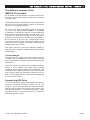
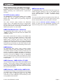
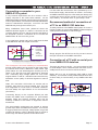
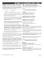
The NMEA 0183 Information sheet Everything you wanted to know about NMEA 0183 (but were afraid to ask) Understanding the NMEA 0183 specification How to connect NMEA 0183 devices together How to understand NMEA 0183 sentence formats Issue 3 Actisense® Contents Important Notices Notices Feedback! NMEA 0183 Introduction 4 4 4 4 The Actisense product range 8 Connecting NMEA talkers to NMEA Listeners Differential NMEA talker 9 9 The basics Electrical specification NMEA 0183 v2.x and v3.x Talker NMEA 0183 v1.x Talker Other Talkers NMEA Talker Limitations Listener specification Communication specification The different versions of the NMEA 0183 standard Format changes Introducing ISO-Drive PC OPTO-Isolation cables NMEA Data Multiplexers / Combiners NMEA Buffers NMEA gateways NMEA Autoswitches Case (1): Standard differential NMEA 0183 v2.0+ Listener Case (2): Single-ended NMEA Listener Single-ended NMEA talker Case (1): Standard differential NMEA 0183 v2.0+ device Case (2): Single ended NMEA interface devices Connecting a computer to your NMEA 0183 system Recommend method of connection of a PC to an NMEA 0183 data bus Testing an NMEA 0183 computer connection with ‘HyperTerminal’ Example data using an Actisense talker device © 2011 Active Research Limited 4 5 5 5 5 5 6 6 7 7 7 7 8 8 8 8 8 9 9 10 10 10 11 11 12 12 Page 2 The NMEA 0183 Information sheet - Issue 3 NMEA 0183 Sentence Format 13 NMEA Contact Information Company Information 16 16 DBT – Depth Below Transducer DPT – Depth MTW – Mean Temperature of Water VHW – Water Speed and Heading VLW – Dual Ground/Water Distance NMEA Version 3 Approved Sentence Formatters © 2011 Active Research Limited 13 13 14 14 14 15 Page 3 Actisense® Important Notices NMEA 0183 Introduction This Actisense document is for informational purposes only, and to the best of our knowledge, the information contained within is accurate and true. Any use of the information contained within this document is solely at the user’s own risk. The National Marine Electronics Association (NMEA) developed a standard over 20 years ago that defines the interface between various pieces of marine electronic equipment and navigational computers, allowing them to talk together and share vital information. No responsibility will be accepted for any personal injury or damage to a boat or its connected equipment resulting directly or indirectly from information contained within. The NMEA 0183 standard slowly became the common method by which marine electronics devices could talk to one another. The standard specifies both the electrical connections that make up an NMEA system, the communications method of transmitting the data, and the format of the data sentences that carry the NMEA information. Navigational equipment used on board a boat can be critical to the safe passage of the vessel, so if in doubt, contact an expert equipment installer before making any modifications to your current system. Unfortunately, we cannot published the entire NMEA 0183 standard here, as it is copyrighted by NMEA. A full copy of this standard is available for purchase at the NMEA web site - see the NMEA contact details at end of document. We would recommend anyone designing equipment for connection to an NMEA 0183 network to obtain an official copy. Notices When using this document, keep the following in mind: The information contained in this document and any specifications thereof may be changed without prior notice. To obtain up-to-date information, contact Active Research Limited (refer to the Contact Information section) or visit the Actisense website (www.actisense.com). Active Research Limited will not be liable for infringement of copyright, industrial property right, or other rights of a third party caused by the use of information or drawings described in this document. The NMEA 0183 standard is a purely digital data transmission scheme, using ‘1’s and ‘0’s in a binary format, to communicate a digital representation of the required information (depth, speed etc.) to a connected device. The need for NMEA 0183 evolved from the earlier “NMEA 0180” and “NMEA 0182” standards. Because they differ in baud rate and transmission parameters from NMEA 0183, they are completely incompatible with NMEA 0183. Similarly, the new “NMEA 2000” standard is totally different, and the two networks cannot be mixed without using a special gateway device to convert between the two standards such as the Actisense NGW . The basics The NMEA standard defines the electrical signalling, data protocol and sentence formats for a 4800 baud serial data bus. NMEA data is transmitted from an information source such as a GPS, depth sounder, or gyro compass etc. These data sending devices are called “Talkers”. All rights are reserved: The contents of this document may not be transferred or copied without the expressed written permission of Active Research Limited. Equipment receiving this information such as a chartplotter, radar, PC or NMEA display is called a “Listener”. Feedback! Each NMEA 0183 data bus shall have only a single talker but may have many listeners. The talker section of this document explains why this is the case. This document has been produced from some of the knowledge and experience gained by Actisense from many years of experience in NMEA interfacing. Please report any errors, omissions or inaccuracies directly to Actisense - we intend this document to be a useful resource tool to installers new to NMEA 0183 and inevitably we may have missed out the vital piece of information that they may have required to achieve a working NMEA 0183 system. © 2011 Active Research Limited Page 4 The NMEA 0183 Information sheet - Issue 3 Electrical specification The latest specifications for NMEA 0183 (version 2 and onwards) should, as a minimum, meet the requirements of the computer standard “RS422” (Standard EIA-422-A). They use +5 / 0 volt signalling, which is low voltage and easy to interface to computer equipment. However, voltage levels present on an NMEA 0183 bus can be much greater - up to +/- 15 volts, particularly where older equipment is used, as the original version 1 specification used +/- 12-15 volt signalling. Thus, all NMEA 0183 inputs conforming to v2.0 and higher should be capable of receiving +/- 15 volt differential signals without suffering damage. In practice, this means line A is zero volts and line B is at 5 volts on an NMEA output when a logical “1” is present,. For a logical “0” line A is at 5 volts and line B is at 0 volts. These voltages would be present only when no load is attached. NMEA 0183 v1.x Talker NMEA 0183 version 1 talkers used slightly different connection methods and signal levels. Devices had just NMEA 0183 Talker before v.2.0 The NMEA 0183 specification also requires that all receiving equipment must be opto-isolated; this optoisolation requirement reduces the chances of interference and removes the problem of ground loop effects. Data Ground All connections should be made using twisted pair cabling, with a shield. To prevent ground loops, the shield should only be connected at one end - NMEA specifies that the shield should be connected to the Talker chassis. NMEA 0183 v2.x and v3.x Talker As specified in RS422, version 2 and newer NMEA connections are labelled “A”, “B” and Shield. Sometimes the signals are label Data + and Data -, these relate to NMEA A and NMEA B respectively. The signal states provided by the Talker are those specified in EIA-422-A. This states that the logical “1” or STOP bit state is defined by a negative voltage one line “A” with respect to line “B”. A logical “0” or START bit is defined by a positive voltage on line “A” with respect to line “B”. A pictorial representation of an RS422 type talker can be seen in the diagram below: NMEA 0183 Talker v.2.0 onwards A B Shield one “NMEA” data line (‘Tx’ ‘Data’ or ‘Out’), and used the ground as the other line - similar to a computer serial port. This connection method is referred to as “single ended” instead of the “differential” method used by NMEA 0183 v2.0 devices. Version 1 talkers also had signal levels similar to that used in the computer ‘RS232’ standard. Here, the data signalling voltage was up to +/- 15v, and the logical “1” or STOP bit state is defined to be within the range -15 to +0.5v. The logical “0” or START bit was defined to be within the range +4.0v to +15.0v. Other Talkers Many devices are produced that are fully compliant with the NMEA 0183 standard. Most simply label the outputs as “DATA” or “TX”, and use the system ground line as the “B” line, as per the version 1 standard, but often the drive voltage is 5 volts, as used in version 2. Many of these talkers are labelled as version 2, but in this case they are referring to the contents of the data format, not the talker. Another limitation of these circuits is that they often use low power driver chips, and thus can often only talk to one listener instead of many. This means that an “NMEA Buffer” must be used to drive multiple listeners NMEA Talker Limitations The A is the regular output from the amplifier, and the B is the “inverted” output. The Shield or ground is connected to the talker chassis as shown. © 2011 Active Research Limited NMEA Talker outputs cannot be turned off, or switched into a receive mode, which means that the outputs are continuously driven. This is why only one talker can be present on a single Page 5 Actisense® NMEA 0183 bus at any one time. To combine data buses, you must use a multiplexer, such as the Actisense NDC. This safely receives the data from multiple talkers, and combines it together into a single stream. Two or more Talkers are simply not possible on the same data line as they are not synchronised to each other, and will attempt to ‘talk’ at the same time (over each other). It is also likely that one Talker will have a stronger drive circuit, and the other talker will not even get to send anything. This will resulting in corruption or total loss of the NMEA data, and potentially in disaster if valuable data such as navigation information is lost or corrupted so that it is incorrect and/or misleading. Connecting two talkers together can even lead to one or both of the Talkers becoming damaged. A Talker can be connected to multiple Listeners, but often many talkers used in electronic devices on the market do not provide enough driver current to talk to more than one or two listeners at one time, thus special NMEA amplifiers or “buffers” need to be employed. In addition, NMEA 0183 version 3.0 added a new baud rate of 38400 baud. This is known as “NMEA 0183-HS” This was to allow for the latest ARPA and AIS equipment which require a higher baud rate link to send the larger quantity of information they produce in a timely manner. The data sent is all in printable ASCII form (data bit 7 is always zero in NMEA 0183 data transmissions, and all characters should be between ASCII HEX 20 and HEX 7E), so may be viewed directly on a PC “terminal” type program (like ‘HyperTerminal’) - even though what is seen may not make much sense. Note: NMEA 0183-HS or NMEA 0183 v3 is in no way related to the new NMEA 2000 standard (as is incorrectly suggested by some manufacturers), which uses a totally different electrical connection standard that is not compatible with NMEA 0183 in any way. If you require to convert between NMEA 0183 and the new NMEA 2000 network, the Actisense NMEA 2000 Gateway will allow full bidirectional conversion between these two very different standards. Please visit the Actisense website for full details. Listener specification A listener receiver must be design to operate with a minimum differential input voltage of 2.0 Volts, and not take more than 2.0mA from the line at that voltage. The NMEA standard document shows a circuit that will meet this requirement. Actisense has designed it’s own OPTO input circuit which exceeds this requirement, extending the range of which good data may be successfully received. A Listener must also be OPTO isolated to prevent ground loop problems. Again, many manufacturers have not implemented this and this has caused more problems in installations, as connecting together two grounds of two systems can be a major source of faults on installations. It also causes major issues when connecting a version 2.0 Talker to a version 1.x listener, as connecting the “B” line to the ground causes current to flow every time the “B” line tries to go to +5 volts. Listeners must also be tolerant of the higher voltages used in NMEA version 1 signalling. See ‘ISO-Drive’ section for a solution to this problem. Communication specification The data communication specification for NMEA version 1, 2 and 3 is essentially the same as RS232 with the settings: 4800 baud, 1 start bit, 1 stop bit and “No Parity”. © 2011 Active Research Limited Page 6 The NMEA 0183 Information sheet - Issue 3 The different versions of the NMEA 0183 standard As the NMEA 0183 specification has slowly evolved over the years, connecting one device to another is not always a simple matter. The situation is further complicated, as many manufacturers still use the old (“single ended”) method of connection because it is cheaper to implement. So how can an older type NMEA device be connected to a newer type device? Care is needed – it is possible to damage or overload the output of a newer differential device if it is incorrectly connected to an older device. This is because the older devices used ground as the return, whereas the newer devices actually drive the NMEA “-/ B” line between 5v and 0v. Thus, connecting this output to ground will result in high currents being drawn by the driver instrument, resulting in potential overheating and damage to the driver circuits. See pages 8 and 9 for connection diagrams relating to interconnection of different NMEA 0183 bus and device configurations. Format changes The data format is largely the same between versions of NMEA, with v2.0 adding some extra sentence strings, and removing older (redundant) sentence strings from the specification. There are however problems when interfacing between version 1 and 2 NMEA 0183 where some sentence formatters were changed between the two standards. This means that some older equipment will not work properly when receiving data from equipment sending version 2.0 data. These changes are too fundamental and detailed to go into in this document. Introducing ISO-Drive To solve all the above fundamental interfacing problems, Actisense introduced ISO-Drive outputs on all new products. These outputs provide the essential isolation that will keep a system safe when mixing products from different manufacturers on a complex marine bus. If the ISO-Drive “B” line is connected to ground, no current will flow and the system is safe. © 2011 Active Research Limited Page 7 Actisense® The Actisense product range Actisense produces a full range of products to solve all NMEA interfacing and interconnection requirements, including: PC OPTO-Isolation cables The Actisense PC-OPTO range allows a PC to safely receive data from an NMEA 0183 system, protecting against high voltage spikes and preventing dangerous ground loops. The cable converts neatly between the differential system used on the NMEA 0183 and the “single-ended” RS232 system to provide the best quality of data for the PC port. See section “Connecting a computer to your NMEA 0183 system” for more details. NMEA Autoswitches The Actisense NSW-1 (and some of the NDC range) can enable automatic switching of two or more NMEA 0183 source (“Talker”) devices to select the highest priority device with valid data - in effect - automatic backup protection. This can be used to select the highest priority GPS unit, and automatically switch to the next highest priority GPS device if the first fails for one of a number of reasons. Please visit the Actisense product webpage for full details on these and other Actisense interfacing and Depth sounding product ranges including NMEA 2000. NMEA Data Multiplexers / Combiners The Actisense NDC product range can allow multiple “Talkers” to easily share their data with other NMEA 0183 “Listener” devices. Some NDC models allow for filtering of the NMEA 0183 data to remove any unwanted sentences. A wide range of input / output Baud rates can be set to match any NMEA device. Computer users with a USB port are catered for with the later variants in the range, either being supplied with a USB cable or having upgrade capability. Autoswitching functionality has also been added to later variatns of the NDC, see the Autoswitching section below. NMEA Buffers The Actisense NBF product range provides multiple ISO-Drive outputs to allow several NMEA 0183 devices on separate systems to safely receive the data from one source. The signal is buffered, amplified and isolated to meet the needs of any NMEA 0183 network. If you require more than one source (“Talker”) of data, an Actisense NDC can easily be used. An NBF connected to the output of an NDC will provide multiple isolated data streams from multiple inputs. NMEA Gateway - NMEA 0183 to PC USB The USG product range is the USB to Serial (NMEA 0183) gateway. This provides a totally isolated input and output to connect a PC standard USB port to an NMEA 0183 bus. With bi-directional isolation the USG is even more robust than the PC-OPTO range. NMEA Gateway - NMEA 0183 to NMEA 2000 The NGW product range converts NMEA 0183 sentences into NMEA 2000 messages and vice-versa. The NMEA 0183 end comes in standard NMEA 0183 bare wire connections or with a USB plug to connect directly to a PC running NMEA 0183 software. © 2011 Active Research Limited Page 8 The NMEA 0183 Information sheet - Issue 3 Connecting NMEA talkers to NMEA Listeners Care needs to be taken when connecting different types of NMEA talkers together, particularly where a mixture of NMEA versions is encountered. These pages show common connections for each type of talker and listener, and how to connect between new type differential devices and old type single-ended devices. On page 10 and 11, details are given for connecting an on board PC system to an NMEA 0183 marine electronic bus. Differential NMEA talker These are the recommended methods of connection for a differential, NMEA version 2.0 talker. Case (1): Standard differential NMEA 0183 v2.0+ Listener This device is a differential device conforming in full to the NMEA 0183 v2.0 (or higher) standard, and connects directly to the pins on the differential device. NMEA 0183 Talker (Differential) A B Shield A/ + NMEA B/ - Listener NMEA 0183 version 2 ‘Differential’ Talker connected to NMEA version 2 ‘OPTO-Isolated’ Listener Case (2): Single-ended NMEA Listener To connect the device to the differential output, connect ‘NMEA +/A’ to the device’s ‘NMEA’ input and ‘Ground’ to the ‘Ground’ on the single ended device. It should be able to receive the NMEA data correctly. NMEA 0183 Talker (Differential) A B Shield In G NMEA Listener NMEA 0183 version 2 ‘Differential’ Talker connected to NMEA version 1 ‘Single-ended’ Listener Never connect the ‘NMEA -/B’ to the ground of a single ended receiving instrument. The resulting extra load will at best increase the current consumption of the driver, at worst it could cause serious damage to it. © 2011 Active Research Limited Page 9 Actisense® Single-ended NMEA talker These are the recommended methods of connection for a single-ended, pre - NMEA version 2.0 talker. Many instruments that output version 2.0 formatted strings use a single-ended output. This is often the case with some of the hand-held GPS units such as from Garmin, as the circuitry to produce the differential output is more complex, and requires extra connector pins. Single ended outputs are normally labelled ‘NMEA Tx’, ‘NMEA Out’ or just ‘Data’. The ground connection is used as the data signal reference. Case (1): Standard differential NMEA 0183 v2.0+ device This device is a differential device conforming in full to the NMEA 0183 v2.0 (or higher) standard. NMEA 0183 Single ended talker NMEA Tx Ground A/+ NMEA B/ - Listener NMEA 0183 ‘Single-Ended’ Talker connected to NMEA ‘OPTO-Isolated’ Listener Its “NMEA +/A” input is connected to the “NMEA Tx” output of the single ended device. It’s “NMEA -/B” input is connected to the “Ground” of the single ended device. This connection is required to provide data signal return current path for the opto-isolated NMEA listener. If the NMEA “-/B” input is left floating, then data corruption / errors may occur, or more likely, no data will be seen. Case (2): Single ended NMEA interface devices NMEA 0183 Single ended talker NMEA Tx Ground Rx NMEA GND Listener NMEA 0183 ‘Single-Ended’ Talker connected to NMEA 0183 ‘Single Ended’ Listener This device is a single ended listener. This listener is simply connected as “NMEA Out / Data or Tx” to “(NMEA) In / Rx” and “Ground” to “Ground” of the single ended device © 2011 Active Research Limited Page 10 The NMEA 0183 Information sheet - Issue 3 Connecting a computer to your NMEA 0183 system A very common requirement now is to connect a PC or Laptop computer to the marine data network. As the NMEA specification basically uses the same asynchronous Comms specification in accordance with ANSI standard as used on a standard PC serial port, most PC’s can read NMEA directly through their Comms port. Many installations have been performed where the NMEA 0183 data signal of a talker is connected to the computer RS232 “Rx” line, and the ground of the talker to the Computer “Ground “ connection. Do not connect the NMEA Talker “B” line to the PC ground. It is also often the case that the PC is powered by an on board mains supply, derived from an inverter. Connecting an NMEA 0183 data signal to a PC serial port directly may connect the ground of the inverter to the ground of the ship’s battery. This would cause a “ground-loop” issue. Recommend method of connection of a PC to an NMEA 0183 data bus To safely interface to the NMEA 0183 system on a boat, it is best to obtain an opto-isolated NMEA to RS232 adapter cable (see the Actisense PC-OPTO range). NMEA 0183 Talker v.2.0 onwards B In our experience, almost 100% of PC’s will show the data of the NMEA link with this simple connection. NMEA 0183 Talker v.2.0 onwards A Shield PIN 2 PIN 5 Standard Personal Computer 9-PIN ‘D-Type’ Serial Port A functional but not-recommended method often used to connection a PC or Laptop to a marine network This is dangerous and most definitely not recommended, as high voltage spikes can be present on the signal cable, by induction from motors, alternators, radar pulses, high power radios etc. and will damage the Comms port on a laptop or PC that has only been designed for domestic use. Particularly large voltage spikes can occur when engines switch on and off - outboard motors are often very hazardous to the quality of electrical signals on board a boat. Often, this connection will function for months with no problem, then fail at the worst possible time. This has even happened to our lab PCs in controlled conditions. We now always use opto-isolators on our test benches (see below). Connecting directly to the computer RS232 port also breaks the NMEA 0183 requirement for opto-isolation between Talker and Listener; therefore there may be warranty conditions to this effect on equipment sold for marine use. A Shield PC-OPTO-1 Standard Personal Computer 9-PIN ‘D-Type’ Serial Port Recommended connection of a PC or Laptop to a talker Simply plug the PC-OPTO into the PC port and connect the open end wires to the NMEA 0183 lines. Connection of a PC with no serial port to an NMEA 0183 data bus There are two ways to do this - you can purchase a USB to serial adapter, which creates a serial connection from a USB port and connect to the PC-OPTO as above. Better still is to use an Actisense USG USB to serial Gateway. This creates a totally isolated RS422 driver and receiver ready to connect safely to any NMEA 0183 data bus NMEA 0183 Talker v.2.0 onwards A B Shield Connecting a PC or Laptop USB port safely to a marine network Note the isolated output of the USG-1 allows safe driving of the marine bus from the PC This opto-isolation requirement was created to prevent ground loops within an NMEA 0183 system - this can be a bigger problem than the high voltage spikes, as ground currents can destroy a PC by allowing amps of current to flow through the delicate printed circuit boards within. © 2011 Active Research Limited Page 11 Actisense® Testing an NMEA 0183 computer connection with Actisense NMEA Reader NMEA Reader is free software for PC users to easily monitor and debug NMEA data. Capable of displaying both NMEA 0183 and NMEA 2000 data NMEA Reader can be an invaluable tool for installing an NMEA network. NMEA Reader can be found on the software updates page on the Actisense website. Example data using an Actisense talker device By connecting a so-called “Triducer” from a company like Airmar (www.airmar.com), or direct from the Actisense , it is possible to measure the four quantities of depth, speed, log (distance) and temperature in just one device with a considerable cost saving versus buying each transducer/device separately. Plus, all this data is supplied through just one NMEA 0183 port. The Actisense DST (active depth sounder module) has the same Digital Signal Processor unit, but can connect to any analogue Triducer (Depth, Speed & Temperature), Biducer (Depth & Temperature), or Depth only transducer. It allows easy conversion of the analogue transducer signals into the digital NMEA 0183 sentences. These two sensor types output the NMEA strings ‘DBT’, ‘DPT’, ‘MTW’, ‘VHW’ and ‘VLW’. Why do the strings have these names, and what data do they contain? Refer to the NMEA 0183 Sentence Format section of this document for more details. © 2011 Active Research Limited Page 12 The NMEA 0183 Information sheet - Issue 3 NMEA 0183 Sentence Format All NMEA 0183 data is sent in the form of text sentences, each beginning with a ‘$’ or ‘!’ symbol, and use commas to separate each part of the sentence. NMEA codes are plain ‘ASCII’ text, and have the following format: $yyXXX,……… *xx <0D><0A> • The sentence always starts with a ‘$’ or ‘!’ symbol • A 2-digit ‘yy’ code follows, giving the instrument type (e.g. for a GPS device this should be ‘GP’, and for a depth sounder this should be ‘SD’) • • • • A 3-digit ‘XXX’ code follows, giving the sentence data type (e.g. ‘GGA’ is a ‘Global Positioning System Fix Data’ sentence, and ‘DBT’ is a ‘Depth Below Transducer’ sentence) A comma follows, then the contents of the sentence data, which changes depending on the data type and the current values of what is being monitored. The final part is an optional two-digit checksum optional, but all good equipment will include this to help safe-guard the data in the sentence. The checksum is preceded by the ‘*’ character and is calculated by taking the 8-bit exclusive-OR of all characters in the sentence, including ‘,’ delimiters, between but not including the ‘$’ / ’!’ and ‘*’ delimiters. The string always ends with a carriage return and linefeed combination (Hex 0D 0A, ASCII ‘\r\n’) To better explain the NMEA 0183 format, the next section details all the NMEA 0183 sentences output by the Actisense DST unit. The 3-digit ‘XXX’ is replaced by the 3-digit codes presented below. In the data format below, the values DATA_#### represents the digital data, and can have any number of digits before and after the decimal point (if included). This makes the system compatible with all levels of required output precision, depending on the ability of the sensor. Some data fields are optional – i.e. can be left out, by having no data between the comma delimiters. The checksums shown are for example purposes only and will only be correct with a particular combination of data. It would not be feasible to copy out the entire specification here, but there is more data on further strings in the links section at the end of this document. © 2011 Active Research Limited DBT – Depth Below Transducer Water depth referenced to the transducer’s position. Depth value expressed in feet, metres and fathoms. Format: $xxDBT,DATA_FEET,f,DATA_METRES,M, DATA_FATHOMS,F*hh<0D><0A> Examples Standard precision, without checksum: $SDDBT,6.6,f,2.0,M,1.1,F<0D><0A> 6.6 feet / 2.0 metres / 1.1 fathoms. Extended precision, without checksum: $SDDBT,6.66,f,2.03,M,1.10,F<0D><0A> 6.66 feet / 2.03 metres / 1.11 fathoms. Standard precision, with checksum: $SDDBT,8.1,f,2.4,M,1.3,F*0B<0D><0A> 8.1 feet / 2.4 metres / 1.3 fathoms. $SDDBT,8.1,f,2.4,M,,<0D><0A> 8.1 feet / 2.4 metres / No fathom output. DPT – Depth Water depth relative to the transducer, the depth offset of the transducer, and maximum depth that the sounder can detect a sea-bed (all in metres only). Positive offsets provide distance from the transducer to the water line. Negative offsets provide distance from the transducer to the keel. Not all NMEA 0183 devices that output this sentence can have their depth offset changed. In this case, the depth offset will always be zero, or not included. NMEA 0183 v2.0 sentences will not include the maximum depth range value at all, as it was added in v3.0. Format: $xxDPT,DATA_METRES,OFFSET_METRES, MAXIMUM_METRES*hh<0D><0A> Examples Standard precision, without checksum: $SDDPT,76.1,0.0,100,<0D><0A> 76.1 metres, zero depth offset, 100 metres maximum depth range. Standard precision, with checksum: $SDDPT,2.4,,*7F<0D><0A> 2.4 metres, no depth offset or maximum depth range output (When depth offset and maximum depth values are unknown by the depth sounder). Page 13 Actisense® MTW – Mean Temperature of Water Water temperature in degrees centigrade. Format: $xxMTW,DATA_TEMPERATURE_C,C*hh<0D><0A> Example Extended precision, with checksum: $YXMTW,17.75,C*5D<0D><0A> 17.75 degrees centigrade. VHW – Water Speed and Heading The compass heading to which the vessel is currently pointing, and the speed of the vessel through the water. Format: $xxVHW,DATA_HEADING_DEGRESS_TRUE,T, DATA_HEADING_DEG_MAGNETIC,M, DATA_SPEED_KNOTS,N, DATA_SPEED_KMH*hh<0D><0A> Example Standard precision, with checksum: $VWVHW, , , , ,0.0,N,0.0,K*4D<0D><0A> No heading data provided (as not available), Water speed 0.0 Knots, and 0.0 Km/h. VLW – Dual Ground/Water Distance The distance travelled by the vessel, relative to the water and over the ground. Trip distances are the distances travelled since this value was last reset, thereby resetting at the beginning of a trip, the trip distance is given. Not all NMEA 0183 device that output this sentence can have their trip distance reset - in this case, a power reset will reset both distances. Format: $xxVLW,DATA_TOTAL_WATER_DISTANCE_NM,N, DATA_TRIP_WATER_DISTANCE_NM,N, DATA_TOTAL_GROUND_DISTANCE_NM,N, DATA_TRIP_GROUND_DISTANCE_NM,N *hh<0D><0A> Example $VWVLW,2.8,N,2.8,N*4C Total water distance travelled 2.8 nautical miles, and Trip water distance 2.8 NM (since last reset). The ground distance values are not included and as the checksum has been used to terminate the sentence, the comma and ‘N’ characters of the ground values do not need to be included in the sentence. This fore-shortening of the sentence by using the checksum can be used in any NMEA 0183 sentence. © 2011 Active Research Limited Page 14 The NMEA 0183 Information sheet - Issue 3 NMEA Version 3 Approved Sentence Formatters This list shows how the three letter formatters expand into a more meaningful description of the contents of the NMEA 0183 sentence. To discover the contents of the actual sentences, you must purchase the standard from the NMEA (refer to the NMEA Contact Information). Many other sentence formatters exist, that were specified for previous version of the NMEA 0183 standard, but this list is the current list recommended by the NMEA - all other formatters are effectively “retired” and should not be adopted on new designs. AAM ABK ACA ACS AIR ALM ALR APB BEC BOD BWC BWR BWW CUR DBT DCN DPT DSC DSE DSI DSR DTM FSI GBS GGA GLC GLL GMP GNS GRS GSA GST GSV HDG HDT HMR HMS HSC HTC HTD LCD LRF LTI LR1 LR2 LR3 Waypoint Arrival Alarm UAIS Addressed and binary broadcast acknowledgement UAIS Regional Channel Assignment Message UAIS Channel management information Source UAIS Interrogation Request GPS Almanac Data Set Alarm State Heading/Track Controller (Autopilot) Sentence “B” Bearing and Distance to Waypoint – Dead Reckoning Bearing – Origin to Destination Bearing and Distance to Waypoint Bearing and Distance to Waypoint – Rhumb Line Bearing – Waypoint to Waypoint Water Current Layer Depth Below Transducer Decca Position Depth Digital Selective Calling Information Expanded Digital Selective Calling DSC Transponder Initialize DCS Transponder Response Datum Reference Frequency Set Information GNSS Satellite Fault Detection Global Positioning System Fix Data Geographic Position – Loran C Geographic Position – Latitude/Longitude GNSS Map Projection Fix Data GNSS Fix Data GNSS Range Residues GNSS DOP and Active Satellites GNSS Pseudo range Error Statistics GNSS Satellites in View Heading, Deviation and Variation Heading, True Heading Monitor Receive Heading Monitor Set Heading Steering Command Heading/Track Control Command Heading/Track Control Data Loran-C Signal Data UAIS Long-Range Function UAIS Long-Range Interrogation UAIS Long-Range Reply Sentence 1 UAIS Long-Range Reply Sentence 2 UAIS Long-Range Reply Sentence 3 © 2011 Active Research Limited MLA MSK MSS MTW MWD MWV OSD RMA RMB RMC ROT RPM RSA RSD RTE SFI SSD STN TLB TLL TTM TUT TXT VBW VDR VHW VLW VPW VSD VTG WCV WNC WPL XDR XTE XTR ZDA ZDL ZFO ZTG ABM BBM VDM VDO GLONASS Almanac Data MSK Receiver Interface MSK Receiver Signal Water Temperature Wind Direction and Speed Wind speed and Angle Own Ship Data Recommended Minimum Specific Loran-C Data Recommended Minimum Navigation Information Recommended Minimum Specific GNSS Data Rate of Turn Revolutions Rudder Sensor Angle Radar System Data Routes RTE – Routes Scanning Frequency Information UAIS Ship Static Data Multiple Data ID Target Label Target Latitude and Longitude Tracked Target Message Transmission of Multi-language Text Text Transmission Dual Ground/Water Speed Set and Drift Water Speed and Heading Dual Ground/Water Distance Speed – Measured Parallel to Wind UAIS Voyage Static Data Course Over Ground and Ground Speed Waypoint Closure Velocity Distance – Waypoint to Waypoint Waypoint Location Transducer Measurements Cross-Track Error, Measured Cross-Track Error – Dead Reckoning Time and Date Time and Distance to Variable Point UTC and Time from Origin Waypoint UTC and Time to Destination Waypoint Encapsulation Formatters UAIS Addressed binary and safety related message UAIS Broadcast Binary Message UAIS VHF Data-link Message UAIS VHF Data-link Own-vessel report Page 15 Actisense® NMEA Contact Information NMEA - National Marine Electronics Association 7 Riggs Avenue Severna Park, MD 21146 USA Telephone: Fax: +1 (410) 975 9422 +1 (410) 975 9450 E-mail: Website: [email protected] www.nmea.org Company Information Active Research Limited 5, Wessex Trade Centre Ringwood Road Poole Dorset UK BH12 3PF Telephone: 01202 746682 (International : +44 1202 746682) Actisense on the Web: For advice, support and product details E-mail: Website: [email protected] www.actisense.com Twitter: Facebook: LinkedIn: www.twitter.com/ActisenseNews www.twitter.com/ActisenseTech bit.ly/actibook linkd.in/actisense (All Actisense News and Updates) (Actisense Product Updates) (All Actisense News and Updates) (All Actisense News and Updates) “Actisense” is a registered trademark of Active Research Limited. © 2011 Active Research Limited Page 16