1
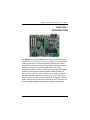
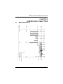
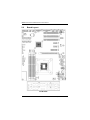
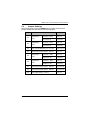
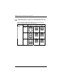
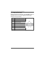
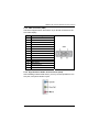
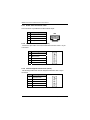
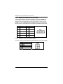
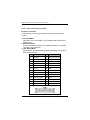
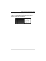
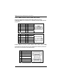
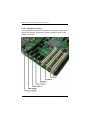
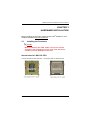
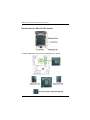
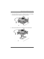
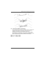
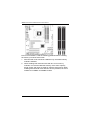
IMB205 Series ® Intel ™ ™ Socket 1156 Core i7 / Core i5 / ™ ® Core i3 / Pentium Processor ATX Industrial Motheroard User’s Manual Disclaimers This manual has been carefully checked and believed to contain accurate information. Axiomtek Co., Ltd. assumes no responsibility for any infringements of patents or any third party’s rights, and any liability arising from such use. Axiomtek does not warrant or assume any legal liability or responsibility for the accuracy, completeness or usefulness of any information in this document. Axiomtek does not make any commitment to update the information in this manual. Axiomtek reserves the right to change or revise this document and/or product at any time without notice. No part of this document may be reproduced, stored in a retrieval system, or transmitted, in any form or by any means, electronic, mechanical, photocopying, recording, or otherwise, without the prior written permission of Axiomtek Co., Ltd. CAUTION If you replace wrong batteries, it causes the danger of explosion. It is recommended by the manufacturer that you follow the manufacturer’s instructions to only replace the same or equivalent type of battery, and dispose of used ones. ©Copyright 2010 Axiomtek Co., Ltd. All Rights Reserved April 2010, Version A1 Printed in Taiwan ii ESD Precautions Computer boards have integrated circuits sensitive to static electricity. To prevent chipsets from electrostatic discharge damage, please take care of the following jobs with precautions: Do not remove boards or integrated circuits from their anti-static packaging until you are ready to install them. Before holding the board or integrated circuit, touch an unpainted portion of the system unit chassis for a few seconds. It discharges static electricity from your body. Wear a wrist-grounding strap, available from most electronic component stores, when handling boards and components. Trademarks Acknowledgments Axiomtek is a trademark of Axiomtek Co., Ltd. ® Windows is a trademark of Microsoft Corporation. AMI is a trademark of American Megatrend Inc. IBM, PC/AT, PS/2, VGA are trademarks of International Business Machines Corporation. ® ™ ™ ™ ® Intel Core i7 / Core i5 / Core i3 / Pentium are trademarks of Intel Corporation. Winbond is a trademark of Winbond Electronics Corp. Realtek is a trademark of Realtek Semi-Conductor Co., Ltd. Other brand names and trademarks are the properties and registered brands of their respective owners. iii Table of Contents Disclaimers ............................................................................................ ii ESD Precautions .................................................................................. iii CHAPTER 1.................................................................................................. 1 INTRODUCTION .......................................................................................... 1 1.1 Specifications..................................................................... 2 1.2 Utilities Supported ............................................................. 4 CHAPTER 2.................................................................................................. 5 JUMPERS AND CONNECTORS.................................................................. 5 2.1 Board Dimensions ............................................................. 5 2.2 Board Layout...................................................................... 6 2.3 Jumper Settings................................................................. 7 2.3.1 COM1 Mode Select Jumpers for RS-232/422/485 (JP4, JP7, JP8) ................................................................................................... 8 2.3.2 COM1~COM4 Mode Select Jumpers (JP1, JP2, JP5, JP6) 9 2.3.3 Audio Output Select Jumper (JP3).................................... 13 2.3.4 CMOS Clear Jumper (JP12) ............................................... 14 2.4 Connectors ....................................................................... 15 2.4.1 DisplayPort Connector (CN1) ............................................ 16 2.4.2 PS/2 Keyboard/Mouse Connector (CN2)........................... 17 2.4.3 COM1/2 Connector (CN3) ................................................... 18 2.4.4 VGA Connector (CN4)......................................................... 19 2.4.5 High Definition Audio Jack Connector (CN5)................... 19 2.4.6 Ethernet with USB Connectors (CN6, CN7) ...................... 20 2.4.7 Audio CD-In Connector: CN9 ............................................. 22 2.4.8 Internal Mouse Connector (CN10) ..................................... 22 2.4.9 Internal Keyboard Connector (CN13) ................................ 22 2.4.10 COM3/COM4 Connectors (CN12, CN16)............................ 23 2.4.11 LAN1/2 Internal LED Connectors (CN14, CN15)............... 23 2.4.12 Digital I/O Port (DIO) Connector (CN20)........................... 24 2.4.13 ATX 4 Pin 12V in Connector (CN21) ................................. 24 2.4.14 Floppy Disk Port Connector (CN24) ................................. 25 2.4.15 Print Port Connector (CN25) ............................................. 26 2.4.16 CPU Fan Connector (CN26) .............................................. 27 2.4.17 USB Connectors (CN27, CN28, CN31, CN34)................... 28 2.4.18 SATA Connectors (CN29, CN30, CN32, CN33, CN37, CN38) ......................................................................................................... 28 2.4.19 Front Panel Connector (CN35).......................................... 29 2.4.20 ATX Power Connector (CN36) .......................................... 30 2.4.21 System Fan Connector (CN39) ......................................... 30 iv 2.4.22 2.4.23 2.4.24 2.4.25 2.4.26 Internal power Connector: CN40 ..................................... 31 SMBUS Connector: CN41 ................................................. 31 PCI Slots ............................................................................ 31 PCI Express x1, x4 Slots .................................................. 31 PCI Express x16 Slot ........................................................ 32 CHAPTER 3................................................................................................ 33 HARDWARE INSTALLATION.................................................................... 33 3.1 Installing the Processor .................................................. 33 3.1.1 Installing the heatsink and fan ........................................ 38 3.1.2 Uninstalling the heatsink and fan.................................... 40 3.2 Installing the Memory ...................................................... 42 3.2.1 Daul Channel Memory Configurtion................................. 43 CHAPTER 4................................................................................................ 45 HARDWARE DESCRIPTION ..................................................................... 45 4.1 Microprocessors .............................................................. 45 4.2 BIOS .................................................................................. 45 4.3 System Memory................................................................ 45 4.4 I/O Port Address Map ...................................................... 46 4.5 Interrupt Controller (IRQ) Map........................................ 47 CHAPTER 5................................................................................................ 48 AMI BIOS SETUP UTILITY ........................................................................ 48 5.1 Starting ............................................................................. 48 5.2 Navigation Keys ............................................................... 48 5.3 Main Menu ........................................................................ 50 5.4 Advanced Menu................................................................ 51 5.5 PCI PnP Menu................................................................... 68 5.6 Boot Menu ........................................................................ 70 5.7 Security Menu .................................................................. 73 5.8 Chipset Menu ................................................................... 74 5.9 Exit Menu .......................................................................... 81 APPENDIX A .............................................................................................. 83 WATCHDOG TIMER .................................................................................. 83 APPENDIX B .............................................................................................. 85 Digital I/O ................................................................................................... 85 APPENDIX C .............................................................................................. 86 CONFIGURING SATA FOR RAID.............................................................. 86 v FUNCTION ................................................................................................. 86 APPENDIX D ............................................................................................ 103 ® Intel iAMT SETTINGS ............................................................................ 103 D.1 Entering MEBx ............................................................... 103 D.2 Set & Change Password................................................ 104 ® D.3 Intel iAMT Web Console............................................... 106 vi IMB205 LGA1156 ATX Motherboard User’s Manual CHAPTER 1 INTRODUCTION The IMB205 ATX industrial Motherboard supports LGA1156 socket ® ™ ™ ™ ® for Intel Core i7 / Core i5 / Core i3 / Pentium processors with 32/45nm technology .The board integrates Intel® Q57 that deliver outstanding system performance through high-bandwidth interfaces, multiple I/O functions for interactive applications and various embedded computing solutions. There are four 240-pin DDR3 DIMM sockets for dual channel architecture DDR3 1066/1333 MHz nonECC memory, maximum memory capacity up to 16GB. The board also features Gigabit Ethernet, six serial ATA-II ports at maximum transfer rate up to 3 GB/s, and SATA RAID 0/1/5/10 by Q57. Twelve ® USB 2.0 high speed compliant ports and built-in Intel HD Audio can achieve the best stability and reliability for industrial applications. Introduction 1 IMB205 LGA1156 ATX Motherboard User’s Manual 1.1 Specifications CPU z Intel® Core™ i7 / Core™ i5 / Core™ i3 / Pentium ® processors Support Intel® Turbo Boost Technology(Note 1) System Chipset z ® Intel Q57 Express Chipset CPU Socket z LGA1156 Socket BIOS z AMI BIOS via 64Mb SPI flash with socket z System Memory Four 240-pin DDR3 DIMM sockets Maximum up to 16GB DDR3 memory Supports 1066/1333MHz non-ECC memory z L3 Cache Varies with CPU z Onboard Multi-I/O Controller: Winbond W83627UHG 4 x Serial Ports: COM 1/2 as double deck D-Sub connectors on the rear I/O and 2x5-pin 2.54 pitch box-header for COM 3/4 ,COM1 support RS-232/422/485 other ports as RS-232 and All ports with +5V/+12V powered 1 x 2x13 Pin 2.54 pitch box-header for Parallel, SPP/EPP/ECP supported 1 x 2x17 Pin 2.54 pitch box-header for FDD 2 Introduction IMB205 LGA1156 ATX Motherboard User’s Manual z USB Interface Tweleve USB ports (four on the Rear I/O, eight ports by 2x5-pin 2.54 pin-header) z Onboard Graphics Intel® Clarkdale integrated Graphics Processing Unit (GPU) processors which goes with Intel® Q57 chipset with VGA,DisplayPort out(Note 2) Memory Size -- Intel DVMT supported Resolution -- VGA output up to a resolution of 2048x1536 pixels with 32-bit color at 75 Hz and DisplayPort output up to 2560x 1600 at 60 Hz. Output Interface -- VGA from DAC output via 15-pin D-Sub connector and DisplayPort from DAC output via DisplayPort connector on the Rear I/O z ® Ethernet ® LAN1 – Intel WG82578DM PHY, supports 10/100/1000 Base-T Gigabit Ethernet, RJ-45 connector on the Rear I/O, with AMT6.0 supported with 5-pin 2.0 pitch wafer for LED LAN2 -- Intel WG82574L NIC, supports 10/100/1000 Base-T Gigabit Ethernet, RJ-45 connector on the Rear I/O with 5-pin 2.0 pitch wafer for LED ® z Serial ATA Six Serial ATA-II ports (3 Gb/s performance) and SATARAID 0/1/5/10 by Intel® Q57 z Audio HD Audio codec Realtek ALC888 for Line/speaker-out & MIC-in on the rear I/O triple deck connector, with LM1877 audio amplifier Support Jack-Detection Support CD In z Expansion Slot 1 x PCI Express2.0 x16 Slot 1 x PCI Express x4 Slot 2 x PCI Express x1 Slot 3 x PCI Slot (32bit/33MHz) Introduction 3 IMB205 LGA1156 ATX Motherboard User’s Manual Watchdog Timer Reset Supported (1-255 levels) z NOTE 1. Intel support Turbo Boost Technology depends on the CPU types. 2. When use the onboard DisplayPort and D-Sub ports, you must install an Intel CPU with integrated graphics. 3. Due to Windows 32-bit operating system limitation, when more than 4 GB of physical memory is installed, the actual memory size displayed will be less than 4 GB. 4. Please load Optimal Defaults after install or uninstall discrete graphics card on PCIe x16 slot. 1.2 Utilities Supported ® z Intel Chipset Drivers z Intel Graphics Drivers z Ethernet Utility and Drivers HD Audio Drivers RAID Utility iAMT Utility and Drivers TPM Utility ® z z z z 4 Introduction IMB205 LGA1156 ATX Motherboard User’s Manual CHAPTER 2 JUMPERS AND CONNECTORS 2.1 Board Dimensions Jumpers and Connectors 5 IMB205 LGA1156 ATX Motherboard User’s Manual 2.2 Board Layout I/O Bracket 6 Jumpers and Connectors IMB205 LGA1156 ATX Motherboard User’s Manual 2.3 Jumper Settings Before applying the power to IMB205 Series, please make sure all jumper settings are defaulted as the following table: JUMPER JP1 JP2 DEFAULT COM4 Mode Select COM3 Mode Select SETTING CN16 Pin 1: DCD Short 7-9 CN16 Pin 8: RI Short 8-10 CN12 Pin 1: DCD Short 7-9 CN12 Pin 8: RI Short 8-10 JP3 Audio Line Out/Speaker Out : Line Out Short 1-3, 2-4 JP4 COM1 Operate Mode Select : RS-232 Short 1-2 JP5 COM1 Mode Select JP6 COM2 Mode Select CN3A Pin 1: DCD Short 7-9 CN3A Pin 9: RI Short 8-10 CN3B Pin 1: DCD Short 7-9 CN3B Pin 9: RI Short 8-10 JP7 COM1 Operate Mode Select : RS-232 Short 3-5,4-6 JP8 COM1 Operate Mode Select : RS-232 Short 3-5,4-6 JP12 Clear CMOS Setting : Normal Short 1-2 Jumpers and Connectors 7 IMB205 LGA1156 ATX Motherboard User’s Manual 2.3.1 COM1 Mode Select Jumpers for RS-232/422/485 (JP4, JP7, JP8) These jumpers select the COM1 port’s communication mode to operate RS-232 or RS-422/485. Description Function COM1 8 Jumper Setting RS-232 (Default) JP4 JP7 JP8 RS-422 JP4 JP7 JP8 RS-485 JP4 JP7 JP8 Jumpers and Connectors IMB205 LGA1156 ATX Motherboard User’s Manual 2.3.2 COM1~COM4 Mode Select Jumpers (JP1, JP2, JP5, JP6) These jumpers select the COM1~COM4 ports’ pin-1 to operate DCD with +5V and +12V power, and pin-8 or pin-9 to operate RI with +5V and +12V. Description COM1 (CN3A) Jumpers and Connectors Function Jumper Setting Pin 1=12V JP5 Pin 1=5V JP5 *Pin 1=DCD (Default) JP5 Pin 9=12V JP5 Pin 9=5V JP5 *Pin 9=RI (Default) JP5 9 IMB205 LGA1156 ATX Motherboard User’s Manual Description COM2 (CN3B) 10 Function Jumper Setting Pin 1=12V JP6 Pin 1=5V JP6 *Pin 1=DCD (Default) JP6 Pin 9=12V JP6 Pin 9=5V JP6 *Pin 9=RI (Default) JP6 Jumpers and Connectors IMB205 LGA1156 ATX Motherboard User’s Manual Description COM3 (CN12) Jumpers and Connectors Function Jumper Setting Pin 1=12V JP2 Pin 1=5V JP2 *Pin 1=DCD (Default) JP2 Pin 8=12V JP2 Pin 8=5V JP2 *Pin 8=RI (Default) JP2 11 IMB205 LGA1156 ATX Motherboard User’s Manual Description COM4 (CN16) 12 Function Jumper Setting Pin 1=12V JP1 Pin 1=5V JP1 *Pin 1=DCD (Default) JP1 Pin 8=12V JP1 Pin 8=5V JP1 *Pin 8=RI (Default) JP1 Jumpers and Connectors IMB205 LGA1156 ATX Motherboard User’s Manual 2.3.3 Audio Output Select Jumper (JP3) This jumper makes the selection of Audio output. Description Function Audio Output Line Out (Default) Selection Speak Out(w/ Amplifier) Jumpers and Connectors Jumper Setting JP3 JP3 13 IMB205 LGA1156 ATX Motherboard User’s Manual 2.3.4 CMOS Clear Jumper (JP12) You may need to use this jumper is to clear the CMOS memory if incorrect BIOS settings. Description Function CMOS Clear Normal (Default) Clear CMOS 14 Jumper Setting JP12 JP12 Jumpers and Connectors IMB205 LGA1156 ATX Motherboard User’s Manual 2.4 Connectors Connectors connect this board with other parts of the system. Loose or improper connection might cause problems. Make sure all connectors are properly and firmly connected. Connector Label Connector Label Display Port CN1 ATX 2x2 12V IN CN21 PS/2 KB/MS Connector CN2 PCI-E x16 SLOT CN23 COM1/2 Connector CN3 Floppy Connector CN24 VGA Connector CN4 Print Connector CN25 HD Audio Connector CN5 CPU FAN Connector CN26 LAN2 & USB Port 8/9 CN6 USB Port 2/3 Connector CN27 LAN1 & USB Port 10/11 CN7 USB Port 6/7 Connector CN28 CD-IN Connector CN9 SATA0~5 Connector Internal Mouse CN10 USB Port 4/5 CN31 COM3 Connector CN12 USB Port 0/1 CN34 Internal Keyboard CN13 Axiomtek Front Panel CN35 LAN2 Internal LED Connector CN14 ATX 12x2 Power Connector CN36 LAN1 Internal LED Connector CN15 SYSTEM FAN CN39 COM4 Connector CN16 Internal Power Connector CN40 PCI-E x1 SLOT CN17,CN18 SMBUS Connector PCI-E x4 SLOT CN19 PCI SLOT 1~3 Digital I/O Connector CN20 DDR3 Long DIMM Slot Jumpers and Connectors CN29,CN30, CN32,CN33, CN37,CN38 CN41 PCI1~3 DIMM1~4 15 IMB205 LGA1156 ATX Motherboard User’s Manual 2.4.1 DisplayPort Connector (CN1) DisplayPort is a digital display interface standard. This connector is used to connect a monitor with DisplayPort inputs. Pin Signal 1 LANE 0 2 GND 3 LANE 0# 4 5 LANE 1 GND 6 LANE 1# 7 LANE 2 8 GND 9 10 LANE 2# LANE 3 11 GND 12 LANE 3# 13 GND 14 15 GND AUX CH 16 GND 17 AUX CH# 18 Hot Plug Detect 19 NC 20 DP_PWR(3.3V) 16 CN1 Jumpers and Connectors IMB205 LGA1156 ATX Motherboard User’s Manual 2.4.2 PS/2 Keyboard/Mouse Connector (CN2) The board supports a keyboard and Mouse interface. Pin Signal Pin Signal CN2 1 K/B Data 7 M/S Data 2 NC 8 NC 3 GND 9 GND 4 +5V 10 +5V 5 K/B CLK 11 M/S CLK 6 NC 12 NC Jumpers and Connectors 17 IMB205 LGA1156 ATX Motherboard User’s Manual 2.4.3 COM1/2 Connector (CN3) CN3 is a double deck D-Sub connector. The upper CN3A is a standard 9-pin DB9 connector for the Serial Port1 RS-232(COM1), jumper selectable with the +5V/12V power capability is on DCD and RI, depending on the jumper setting. Pin 18 Signal 1 Data Carrier Detect (DCD) 2 Receive Data (RXD) 3 Transmit Data (TXD) 4 Data Terminal Ready (DTR) 5 GND 6 Data Set Ready (DSR) 7 Request to Send (RTS) 8 Clear to Send (CTS) 9 Ring Indicator (RI) CN3 Jumpers and Connectors IMB205 LGA1156 ATX Motherboard User’s Manual 2.4.4 VGA Connector (CN4) The board supports CRT/ VGA with a 15-pin D-Sub connector for the CRT VGA display. Pin Signal 1 Red 2 Green 3 Blue 4 NC 5 GND 6 GND 7 GND 8 GND 9 +5V 10 GND 11 NC 12 DDC DATA 13 Horizontal Sync 14 Vertical Sync 15 DDC CLK CN4 2.4.5 High Definition Audio Jack Connector (CN5) After installing onboard audio driver, you may connect speaker to Line Out jack, microphone to MIC in jack. Jumpers and Connectors 19 IMB205 LGA1156 ATX Motherboard User’s Manual 2.4.6 Ethernet with USB Connectors (CN6, CN7) The board is equipped with two high performance Plug and Play Ethernet interface fully compliant with the IEEE 802.3 standard. To connect the board to 10-Base-T, 100-Base-T or 1000 Base-T hub, just plug one end of cable to the Ethernet connector and connect the other end (phone jack) to a 10-Base-T, 100-Base-T or 1000 Base-T hub. The lower double-deck USB Connector (CN6B, CN7B) supports USB 2.0 compliant (480Mbps) that can be connected to any USB peripherals, such as keyboard, mouse, scanner 20 Jumpers and Connectors IMB205 LGA1156 ATX Motherboard User’s Manual LAN LED Indication Description CN6A/CN7A Activity Link LED OFF : No Link Blinking : Data Activity A Speed LED OFF :10 Mbps data rate Green : 100 Mbps data rate Orange : 1G Mbps data rate B Pin 1,5 Signal +5V CN6B 2 USB D8- 3 USB D8+ 4,8 GND 6 USB D9- 7 USB D9+ Pin 1,5 Signal +5V 2 USB D10- 3 USB D10+ 4,8 CN7B GND 6 USB D11- 7 USB D11+ Jumpers and Connectors 21 IMB205 LGA1156 ATX Motherboard User’s Manual 2.4.7 Audio CD-In Connector: CN9 This connector is provided for external audio input. Pin Description 1 CD IN_L 2 GND 3 GND 4 CD IN_R CN9 2.4.8 Internal Mouse Connector (CN10) The board provides the Internal Mouse interface with a 5-pin connector Pin Signal 1 Mouse Clock 2 Mouse Data 3 NC 4 GND 5 +5V CN10 2.4.9 Internal Keyboard Connector (CN13) The board provides the Internal Keyboard interface with a 5-pin connector Pin 22 Signal 1 Keyboard Clock 2 Keyboard Data 3 NC 4 GND 5 +5V CN13 Jumpers and Connectors IMB205 LGA1156 ATX Motherboard User’s Manual 2.4.10 COM3/COM4 Connectors (CN12, CN16) The board has the onboard serial ports COM3, 4 (CN12, CN16), two 2x5-pin 2.54 pitch box-header to support RS-232. Pin Pin Signal Data Carrier Detect 1 (DCD) Signal 2 Data Set Ready (DSR) 3 4 Receive Data (RXD) Request to Send (RTS) 5 Transmit Data (TXD) 6 Clear to Send (CTS) 7 Data Terminal Ready (DTR) 8 Ring Indicator (RI) 10 NC 9 2.4.11 GND CN12/CN16 LAN1/2 Internal LED Connectors (CN14, CN15) Pin Signal 1 Activity Link LED(+) 2 Activity Link LED(-) 3 100 Mbps Speed LED, Low Active 4 +3.3V 5 1G Mbps Speed LED, Low Active Jumpers and Connectors CN14,CN15 23 IMB205 LGA1156 ATX Motherboard User’s Manual 2.4.12 Digital I/O Port (DIO) Connector (CN20) The board is equipped an 8-channel digital I/O connector CN20 that meets requirements for a system customary automation control. The digital I/O can be configured to control cash drawers, sense warning signals from an Uninterrupted Power System (UPS), or perform store security control. The digital I/O is controlled via software programming. Pin Signal Pin Signal 1 DIO 6 2 DIO 1 3 DIO 7 4 DIO 2 5 DIO 8 6 DIO 3 7 GND 8 DIO 4 9 GND 10 DIO 5 CN20 2.4.13 ATX 4 Pin 12V in Connector (CN21) You can connect it to the ATX12V power supply for CPU Core Voltage. Pin 24 Signal 1 GND 2 GND 3 +12V 4 +12V CN21 Jumpers and Connectors IMB205 LGA1156 ATX Motherboard User’s Manual 2.4.14 Floppy Disk Port Connector (CN24) The board provides a 34-pin header type connector CN24 supporting floppy drives. The floppy drives may be any one of the following types: 5.25" 360KB/1.2MB and 3.5" 720KB/1.44MB/2.88MB. Pin Signal Pin Signal Pin Signal 1 GND 2 Drive Density Select 3 GND 4 NC 5 GND 6 NC 7 GND 8 Index# 9 GND 10 13 Motor enable A# GND 11 14 GND Drive Select A# 12 15 NC GND 16 NC 17 GND 18 Direction# 19 GND 20 STEP# 21 GND 22 Write Data# 23 GND 24 Write Gate# 25 28 GND Write Protect# 26 29 Track 0 # NC 27 30 GND Read Data# 31 GND 32 Head Selection# 33 NC 34 Disk Change# CN24 Jumpers and Connectors 25 IMB205 LGA1156 ATX Motherboard User’s Manual 2.4.15 Print Port Connector (CN25) Print Port Connector This board has a multi-mode parallel port to support the following modes: 1. Standard Mode IBM PC/XT, PC/AT and PS/2™ are compatible with bi-directional parallel port. 2. Enhanced Mode Enhanced parallel port (EPP) is compatible with EPP 1.7 and EPP 1.9 (IEEE 1284 compliant). 3. High Speed Mode Microsoft and Hewlett Packard extended capabilities port (ECP) is IEEE 1284 compliant. Pin Signal Pin Signal 1 Strobe# 2 Auto Form Feed# 3 Data 0 4 Error# 5 Data 1 6 Initialize# 7 Data 2 8 Printer Select In# 9 Data 3 10 GND 11 Data 4 12 GND 13 Data 5 14 GND 15 Data 6 16 GND 17 Data 7 18 GND 19 Acknowledge# 20 GND 21 Busy 22 GND 23 Paper Empty# 24 GND 25 Printer Select 26 NC CN25 26 Jumpers and Connectors IMB205 LGA1156 ATX Motherboard User’s Manual 2.4.16 CPU Fan Connector (CN26) A CPU fan is always needed for cooling CPU heat. The CPU fan connector provides power to the CPU fan. Pin Signal 1 GND 2 +12V 3 Rotation Detection 4 Speed Control Jumpers and Connectors CN26 27 IMB205 LGA1156 ATX Motherboard User’s Manual 2.4.17 USB Connectors (CN27, CN28, CN31, CN34) The 10-pin standard Universal Serial Bus (USB) connectors, CN27/29/33/45, on this board are for installing versatile USB interface peripherals. Pin Signal Pin Signal 1 USB +5V 2 USB +5V 3 USB D0- 4 USB D1- 5 USB D0+ 6 USB D1+ 7 GND 8 GND 9 GND 10 GND Pin Signal Pin 1 USB +5V 2 USB +5V 3 USB DX- 4 USB DY- 5 USB DX+ 6 USB DY+ 7 GND 8 GND 10 GND CN34 Signal CN27,CN28,CN31 2.4.18 SATA Connectors (CN29, CN30, CN32, CN33, CN37, CN38) These SATA connectors are for high-speed SATA interface ports and they can be connected to hard disk devices. Pin 28 Signal 1 GND 2 SATA_TX+ 3 SATA_TX- 4 GND 5 SATA_RX- 6 SATA_RX+ 7 GND CN29,CN32,CN37 CN30,CN33,CN38 Jumpers and Connectors IMB205 LGA1156 ATX Motherboard User’s Manual 2.4.19 Front Panel Connector (CN35) Power LED This 3-pin connector, designated at Pins 1 and 5 of CN35, connects the system power LED indicator to its respective switch on the case. Pin 1 is +, and pin 5 is assigned as -. The Power LED lights up when the system is powered ON. Pin 3 is defined as GND. External Speaker and Internal Buzzer Connector Pins 2, 4, 6, and 8 of CN35 connect to the case-mounted speaker unit or internal buzzer. When connecting to an internal buzzer and Short pin2 and pin4. When connecting an external speaker, set these jumpers to Open and install the speaker cable on pin 8 (+) and pin 2 (-). ATX Power On/Off Button This 2-pin connector, designated at Pins 9 and 10 of CN35, connects the power button of the front panel to the IMB205 allowing user to control the power on/off state of the power supply. System Reset Switch Pins 11 and 12 of CN35 connect to the case-mounted reset switch and allow rebooting of your computer instead of turning OFF the power switch. This is a preferred method of rebooting in order to prolong the life of the system’s power supply. HDD Activity LED This connector extends to the hard drive activity LED on the control panel. This LED will flash when the HDD is being accessed. Pins 13 and 14 of CN35 connect the hard disk drive and the front panel HDD LED. Pins 13 is -, and pin 14 is assigned as +. Jumpers and Connectors 29 IMB205 LGA1156 ATX Motherboard User’s Manual 2.4.20 ATX Power Connector (CN36) Steady and sufficient power can be supplied to all components on the board by connecting the power connector. Please make sure all components and devices are properly installed before connecting the power connector. If you use a 24-pin ATX power supply, please remove the small cover from the power connector before plugging in the power cord, otherwise, please do not remove it. Pin Signal Pin Signal 1 3.3V 13 3.3V 2 3.3V 14 -12V 3 GND 15 GND 4 +5V 16 PS_ON 5 GND 17 GND 6 +5V 18 GND 7 GND 19 GND 8 PWR OK 20 -5V 9 5VSB 21 +5V 10 +12V 22 +5V 11 +12V 23 +5V 12 3.3V 24 GND CN36 2.4.21 System Fan Connector (CN39) The System fan connector provides power to the System fan. Pin 30 Description 1 GND 2 +12V 3 Sensor CN39 Jumpers and Connectors IMB205 LGA1156 ATX Motherboard User’s Manual 2.4.22 Internal power Connector: CN40 This connector CN40 is for support power. Pin 2.4.23 Description 1 +12V 2 -12V 3 +5V 4 -5V 5 3,3V 6 5VSB 7 GND 8 GND CN40 SMBUS Connector: CN41 This connector CN41 is for SMBUS interface support. Pin Description 1 SMB_CLOCK 2 NC 3 GND 4 SMB_DATA 5 +5V CN41 2.4.24 PCI Slots The PCI Slots support cards such as a LAN card, SCSI card, USB card and other cards that comply with PCI specifications. Refer to the figure delow for the location of the slots. 2.4.25 PCI Express x1, x4 Slots This motherboard supports PCI Express x1, x4 network card, SCSI card other cards that comply with the PCI Express specifications. Refer to the figure delow for the location of the slots. Jumpers and Connectors 31 IMB205 LGA1156 ATX Motherboard User’s Manual 2.4.26 PCI Express x16 Slot This motherboard supports PCI Express x16 2.0 graphic cards comply with the PCI Express specifications. Refer to the figure delow for the location of the slots. 32 Jumpers and Connectors IMB205 LGA775 ATX Motherboard User’s Manual CHAPTER 3 HARDWARE INSTALLATION ® Before installing the processor, please access Intel website for more detailed information http://www.intel.com . 3.1 Installing the Processor NOTE Before installing the CPU, make sure to turn off the computer and unplug the power cord from the power outlet to prevent damage to the CPU. Introduction to LGA1156 CPU The pin-pad side of LGA1156 CPU Hardware Installation The pin-pad side of LGA1156 CPU 33 IMB205 LGA1156 ATX Motherboard User’s Manual Introduction to LGA1156 CPU socket Locate the alignment keys on the motherboard CPU socket. 34 Hardware Installation IMB205 LGA775 ATX Motherboard User’s Manual Locate the LGA1156 CPU socket on the motherboard. Follow the steps below to correctly install the CPU into the motherboard CPU socket. 1. Press the load lever of LGA1156 CPU socket with your thumb and then move it sideways until it is released from the retention tab, then lift the load lever up. Hardware Installation 35 IMB205 LGA1156 ATX Motherboard User’s Manual 2. Lift the load lever in the direction of the arrow until load plate is completely lifted. 3. Remove the protective cap from the CPU socket. The cap is used to protect the CPU socket against dust and harmful particles. Remove the protective cap only when you are about to install the CPU. Protective cap → 36 Hardware Installation IMB205 LGA775 ATX Motherboard User’s Manual 4. Be careful not touch pin-pad of CPU and pin of CPU socket. 5. Insert the CPU into the CPU socket. The yellow triangular mark on the CPU must align with the bottom left corner of the CPU socket. Note that the alignment keys are matched. Visually inspect if the CPU is seated well into the socket. If not, take out the CPU with pure vertical motion and reinstall. NOTE The CPU fits in only one correct orientation. DO NOT force the CPU into the socket to prevent bending the connectors on the socket and damaging the CPU! Alignment keys Hardware Installation 37 IMB205 LGA1156 ATX Motherboard User’s Manual 6. Close the load plate, and then push down the load lever, ensuring that the front edge of the load plate slides under the shoulder screw(1), insert the load lever under the retention tab(2). 3.1.1 Installing the heatsink and fan NOTE When you buy a boxed Intel ® processor, the package includes the CPU fan and heatsink assembly. If you purchased a separate CPU, ensure that you only use Intel ® -certified heatsink and fan. 38 Hardware Installation IMB205 LGA775 ATX Motherboard User’s Manual 1. Place the heatsink on top of the installed CPU, ensuring that the four fasteners match the holds on the motherboard. 2. Push down two fasteners at a time in a diagonal sequence to secure the heatsink and fan assembly in place. Hardware Installation 39 IMB205 LGA1156 ATX Motherboard User’s Manual 3. Make sure the CPU fan cable is plugged to the CPU fan connector (CN26) on the motherboard. 3.1.2 Uninstalling the heatsink and fan Disconnect the CPU fan cable from the CPU fan connector (CN26) on the motherboard then rotate each fastener counterclockwise. 40 Hardware Installation IMB205 LGA775 ATX Motherboard User’s Manual 1. Pull up two fasteners at a time in a diagonal sequence to disengage the heatsink and fan assembly from the motherboard. 2. Remove the heatsink and fan assembly from the motherboard. Hardware Installation 41 IMB205 LGA1156 ATX Motherboard User’s Manual 3.2 Installing the Memory The board supports four 240-pin DDR3 DIMM memory sockets with maximum memory capacity up to 16GB. NOTE A DDR3 module has the same physical dimensions as a DDR2 DIMM but is notched differently to prevent installation on a DDR2 DIMM socket. Please follow steps below to install the memory modules: 1 2 Push down latches on each side of the DIMM socket. Align the memory module with the socket that notches of memory module must match the socket keys for a correct installation. Install the memory module into the socket and push it firmly down until it is fully seated. The socket latches are levered upwards and clipped on to the edges of the DIMM. Install any remaining DIMM modules. 3 4 42 Hardware Installation IMB205 LGA775 ATX Motherboard User’s Manual 3.2.1 Daul Channel Memory Configurtion This motherboard provides four DDR3 memory sockets and support Daul Channel Technology. After the memory is installed, the BIOS will automatically detect the specifications and capacity of the memory enabling Dual Channel memory sockets are divided into two channels and each channel has two memory sockets as following: ◆Channel 0 : DIMM1, DIMM3 ◆Channel 1 : DIMM2, DIMM4 Hardware Installation 43 IMB205 LGA1156 ATX Motherboard User’s Manual Due to CPU limitations, read the following guidelines before installing the memory in Dual Channel mode. 1. Dual Channel mode cannot be enabled if only one DDR3 memory module is installed. 2. When enabling Dual Channel mode with two or four memory modules, it is recommended that memory of the same capacity, brand, speed, and chips are used for optimum performance. When enabling Dual Channel mode with two memory modules, be sure to install them in DIMM1 and DIMM3 sockets. 44 Hardware Installation IMB205 LGA775 ATX Motherboard User’s Manual CHAPTER 4 HARDWARE DESCRIPTION 4.1 Microprocessors The IMB205 Series supports Intel ® Core ™ i7 / Core ™ i5 / Core ™ i3 / Pentium ® processors, which make your system operated under Windows ® XP, Windows ® Vista, Windows ® 7and Linux environments. The system performance depends on the microprocessor. Make sure all correct settings are arranged for your installed microprocessor to prevent the CPU from damages. 4.2 BIOS The IMB205 Series uses AMI Plug and Play BIOS with a single 64Mbit SPI Flash. 4.3 System Memory The IMB205 Series supports four 240-pin DDR3 DIMM sockets for a maximum memory of 16GB DDR3 SDRAMs. The memory module can come in sizes of 1GB, 2GB and 4GB. Hardware Description 45 IMB205 LGA1156 ATX Motherboard User’s Manual 4.4 I/O Port Address Map Intel ® Core ™ i7 / Core ™ i5 / Core ™ i3 / Pentium ® processors can communicate via I/O ports. There are total 1KB port addresses available for assignment to other devices via I/O expansion cards. 46 Hardware Description IMB205 LGA775 ATX Motherboard User’s Manual 4.5 Interrupt Controller (IRQ) Map The IMB205 Series is a 100% PC compatible control board. It consists of 16 interrupt request lines, and four out of them can be programmable. The mapping list of the 16 interrupt request lines is shown as the following table. IRQ Parity check error IRQ0 System timer IRQ1 Standard 101/102-Key or Microsoft Natural PS/2 Keyboard IRQ2 Interrupt rerouting from IRQ8 through IRQ15 IRQ3 Communication Port (COM2) IRQ4 Communication Port (COM1) IRQ5 PCI Device Share IRQ7 Parallel port IRQ8 System CMOS/real time clock IRQ9 Microsoft ACPI-Compliant System IRQ10 PCI Device Share IRQ11 PCI Device Share IRQ12 Microsoft PS/2 Mouse IRQ13 Numeric data processor IRQ14 Primary IDE Channel IRQ15 Secondary IDE Channel Hardware Description 47 IMB205 LGA1156 ATX Motherboard User’s Manual CHAPTER 5 AMI BIOS SETUP UTILITY This chapter provides users with detailed description how to set up basic system configuration through the AMIBIOS8 BIOS setup utility. 5.1 Starting To enter the setup screens, follow the steps below: 1. 2. Turn on the computer and press the <Del> key immediately. After you press the <Delete> key, the main BIOS setup menu displays. You can access the other setup screens from the main BIOS setup menu, such as the Chipset and Power menus. 5.2 Navigation Keys The BIOS setup/utility uses a key-based navigation system called hot keys. Most of the BIOS setup utility hot keys can be used at any time during the setup navigation process. These keys include <F1>, <F10>, <Enter>, <ESC>, <Arrow> keys, and so on. NOTE Some of navigation keys differ from one screen to another. 48 AMI Bios Setup Utility IMB205 LGA1156 ATX Motherboard User’s Manual Å Left/Right The Left <Arrow> keys allow you to select a setup screen. ÇÈ Up/Down The Up and Down <Arrow> keys allow you to select a setup screen or sub-screen. +− Plus/Minus The Plus and Minus <Arrow> keys allow you to change the field value of a particular setup item. Tab The <Tab> key allows you to select setup fields. F1 The <F1> key allows you to display the General Help screen. F10 The <F10> key allows you to save any changes you have made and exit Setup. Press the <F10> key to save your changes. Esc The <Esc> key allows you to discard any changes you have made and exit the Setup. Press the <Esc> key to exit the setup without saving your changes. Enter AMI Bios Setup Utility The <Enter> key allows you to display or change the setup option listed for a particular setup item. The <Enter> key can also allow you to display the setup subscreens. 49 IMB205 LGA1156 ATX Motherboard User’s Manual 5.3 Main Menu When you first enter the Setup Utility, you will enter the Main setup screen. You can always return to the Main setup screen by selecting the Main tab. There are two Main Setup options. They are described in this section. The Main BIOS Setup screen is shown below. z System Time/Date Use this option to change the system time and date. Highlight System Time or System Date using the <Arrow> keys. Enter new values through the keyboard. Press the <Tab> key or the <Arrow> keys to move between fields. The date must be entered in MM/DD/YY format. The time is entered in HH:MM:SS format. 50 AMI Bios Setup Utility IMB205 LGA1156 ATX Motherboard User’s Manual 5.4 Advanced Menu The Advanced menu allows users to set configuration of the CPU and other system devices. You can select any of the items in the left frame of the screen to go to the sub menus: CPU Configuration IDE Configuration Floppy Configuration Super IO Configuration Hardware Health Configuration ACPI Configuration AHCI Configuration Intel AMT Configuration Intel VT-d Configuration PCI Express Configuration Remote Acces Configuration Trusted Computing USB Configuration For items marked with “f”, please press <Enter> for more options. AMI Bios Setup Utility 51 IMB205 LGA1156 ATX Motherboard User’s Manual 52 AMI Bios Setup Utility IMB205 LGA1156 ATX Motherboard User’s Manual z CPU Configuration This screen shows the CPU Configuration, and you can change the value of the selected option. ¾ Hardware Prefetcher You can let the processor fetches data and instructions from the memory into the caches that are likely to be required in the near future. This reduces the latency associated with memory reads. ¾ Intel® Virtualization Tech Allows a hardware platform to run multiple operating systems separately and simultaneously, enabling one system to virtually function as several systems. ¾ A20M Allow Legacy OSes to be compatible with APs. AMI Bios Setup Utility 53 IMB205 LGA1156 ATX Motherboard User’s Manual z IDE Configuration You can use this screen to select options for the IDE Configuration, and change the value of the selected option. A description of the selected item appears on the right side of the screen. For items marked with “f”, please press <Enter> for more options. 54 ¾ SATA#1 IDE Configuration Use this item to control the onboard SATA controller. Here are the options for your selection, Compatible, Enhanced. ¾ SATA#2 IDE Configuration Use this item to control the onboard SATA controller. Here are the options for your selection, Enhanced and Disabled. ¾ Primary/Secondary IDE Master/Slave Select one of the hard disk drives to configure IDE devices installed in the system by pressing <Enter> for more options. AMI Bios Setup Utility IMB205 LGA1156 ATX Motherboard User’s Manual ¾ Third IDE Master Select one of the hard disk drives to configure IDE devices installed in the system by pressing <Enter> for more options. ¾ Fourth IDE Master Select one of the hard disk drives to configure IDE devices installed in the system by pressing <Enter> for more options. AMI Bios Setup Utility 55 IMB205 LGA1156 ATX Motherboard User’s Manual z SuperIO Configuration You can use this screen to select options for the SuperIO Configuration, and change the value of the selected option. A description of the selected item appears on the right side of the screen. 56 ¾ Serial Port1 Address This option specifies the base I/O port address and Default setting is 3F8 ¾ Serial Port2 Address This option specifies the base I/O port address and Default setting is 2F8. ¾ Serial Port3 Address This option specifies the base I/O port address and Default setting is 3E8 AMI Bios Setup Utility IMB205 LGA1156 ATX Motherboard User’s Manual ¾ Serial Port4 Address This option specifies the base I/O port address and Default setting is 2E8 ¾ Parallel Port Address This item allows you to determine the I/O address for onboard parallel port. There are several options for your selection. z Parallel Port Mode Select an operating mode for the onboard parallel (printer) port. z Parallel Port IRQ Use this item to setting the IRQ for onboard parallel port AMI Bios Setup Utility 57 IMB205 LGA1156 ATX Motherboard User’s Manual z Hardware Health Configuration This screen shows the Hardware Health Configuration, and a description of the selected item appears on the right side of the screen. ¾ 58 H/W Health Configuration This screen displays the temperature of CPU and System, Fan Speed, Vcore, etc. AMI Bios Setup Utility IMB205 LGA1156 ATX Motherboard User’s Manual z ACPI Configuration You can use this screen to select options for the ACPI Configuration, and change the value of the selected option. A description of the selected item appears on the right side of the screen. ¾ General ACPI Configuration Scroll to this item and press <Enter> to view the General ACPI Configuration sub menu, which contains General ACPI (Advanced Configuration and Power Management Interface) options for your configuration. ¾ General ACPI Configuration/Suspend mode Allow you to select the Advanced Configuration and Power Interface (ACPI) state to be used for system suspend. Here are the options for your selection, S1 (POS), S3 (STR) and Auto. AMI Bios Setup Utility 59 IMB205 LGA1156 ATX Motherboard User’s Manual 60 ¾ Advanced ACPI Configuration Scroll to this item and press <Enter> to view the Advanced ACPI Configuration sub menu, which contains Advanced ACPI (Advanced Configuration and Power Management Interface) options for your configuration. ¾ Advanced ACPI Configuration/ACPI Version Features Allow you to select Version for the Advanced Configuration and Power Interface (ACPI). Here are the options for your selection, ACPI v1.0, ACPI v2.0 and ACPI v3.0. ¾ Advanced ACPI Configuration/ACPI APIC support Allows you to Enabled or Disabled the Advanced Configuration and Power Interface (ACPI) support in the Application-Specific Integrated Circuit (ASIC). When set to Enabled, the ACPI APIC table pointer is included in the RSDT pointer list. AMI Bios Setup Utility IMB205 LGA1156 ATX Motherboard User’s Manual z AHCI Configuration You can use this screen to select options for the AHCI Configuration, and change the value of the selected option. A description of the selected item appears on the right side of the screen. ¾ AHCI BIOS Support You can enable or disable this item to control the AHCI function of the SATA controller. AMI Bios Setup Utility 61 IMB205 LGA1156 ATX Motherboard User’s Manual z Intel AMT Configuration You can use this screen to select options for the Intel AMT Configuration, and change the value of the selected option. A description of the selected item appears on the right side of the screen. 62 ¾ Intel AMT Support You can enable this item to support AMT (active management technology) function to follow up the procedure for the access to AMI program screen. ¾ Unconfigure AMT/ME Use this item to unconfigure the AMT/ME settings. AMI Bios Setup Utility IMB205 LGA1156 ATX Motherboard User’s Manual z Intel VT-d Configuration You can use this screen to select options for the Intel VT-d Configuration, and change the value of the selected option. A description of the selected item appears on the right side of the screen. ¾ Intel VT-d Virtualization Technology for Directed I/O (VT-d) extends Virtualization Technology (VT) roadmap, by providing hardware assists for virtualization solution. VT-d can help end users improve security and reliability of the systems and also improve performance of I/O devices in virtualized environment. Here are the options for your selection, Disabled and Enabled. AMI Bios Setup Utility 63 IMB205 LGA1156 ATX Motherboard User’s Manual z Remote Access Configuration You can use this screen to select options for the Remote Access Configuration, and change the value of the selected option. A description of the selected item appears on the right side of the screen. ¾ 64 Remote Access Use this item to enable or disable the Remote Access function. AMI Bios Setup Utility IMB205 LGA1156 ATX Motherboard User’s Manual z PCI Express Configuration This screen shows the PCI Express Configuration, and you can change its value. A description of the selected item appears on the right side of the screen. ¾ Active State Power-Management Use this item to enable or disable the function of Active State Power-Management to provide you with lower power consumption. The default setting is Disabled. AMI Bios Setup Utility 65 IMB205 LGA1156 ATX Motherboard User’s Manual z Trusted Computing You can use this screen to select options for the Trusted Computing, and change the value of the selected option. A description of the selected item appears on the right side of the screen. ¾ 66 TCG/TPM SUPPORT Use this item to control the Trusted Platform Module (TPM) function and Default setting is No. AMI Bios Setup Utility IMB205 LGA1156 ATX Motherboard User’s Manual z USB Configuration You can use this screen to select options for the USB Configuration, and change the value of the selected option. A description of the selected item appears on the right side of the screen. ¾ Legacy USB Support Use this item to enable or disable support for USB device on legacy operating system. The default setting is Enabled. ¾ USB 2.0 Controller Mode Use this item to configure the USB 2.0 controller. The default setting is HiSpeed. ¾ BIOS EHCI Hand-Off Enabling this item provide the support for operating systems without an EHCI hand-off feature. The default setting is enabled. AMI Bios Setup Utility 67 IMB205 LGA1156 ATX Motherboard User’s Manual 5.5 PCI PnP Menu The PCI PnP menu allows users to change the advanced settings for PCI/PnP devices. 68 ¾ Clear NVRAM Use this item to clear the data in the NVRAM (CMOS). Here are the options for your selection, No and Yes. ¾ Plug & Play O/S When the setting is No, Use this item to configure all the devices in the system. When the setting is yes and if you install a Plug and Play operating system, the operating system configures the Plug and Play devices not required for boot. The default setting is No. AMI Bios Setup Utility IMB205 LGA1156 ATX Motherboard User’s Manual ¾ PCI Latency Timer This item controls how long a PCI device can hold the PCI bus before another takes over. The longer the latency, the longer the PCI device can retain control of the bus before handing it over to another PCI device. There are several options for your selection. ¾ Allocate IRQ to PCI VGA This item allows BIOS to choose an IRQ to assign for the PCI VGA card. Here are the options for your selection, No and Yes. ¾ PCI IDE BusMaster This item is a toggle for the built-in driver that allows the onboard IDE controller to perform DMA (Direct Memory Access) transfer. Here are the options for your selection, Disabled and Enabled. ¾ IRQ3/4/5/7/9/10/11/14/15 These items will allow you to assign each system interrupt a type, depending on the type of device using the interrupt. The option “Available” means the IRQ is going to assign automatically. Here are the options for your selection, Available and Reserved. AMI Bios Setup Utility 69 IMB205 LGA1156 ATX Motherboard User’s Manual 5.6 Boot Menu The Boot menu allows users to change boot options of the system. You can select any of the items in the left frame of the screen to go to the sub menus: Boot Settings Configuration Boot Device Priority Hard Disk Drives For items marked with “f”, please press <Enter> for more options. 70 AMI Bios Setup Utility IMB205 LGA1156 ATX Motherboard User’s Manual z Boot Settings Configuration ¾ Quick Boot Enabling this item lets the BIOS skip certain tests while booting. The default setting is Enabled. ¾ AddOn ROM Display Mode This item selects the display mode for option ROM. The default setting is Force BIOS. ¾ Boot Num-Lock Use this item to select the power-on state for the NumLock. The default setting is On. ¾ PS/2 Mouse Support This item determines if the BIOS should reserve IRQ12 for the PS/2 mouse or allow other devices to make use of this IRQ. Here are the options for your selection, Auto, Enabled and Disabled. AMI Bios Setup Utility 71 IMB205 LGA1156 ATX Motherboard User’s Manual z ¾ Wait For ‘F1’ Of Error If this item is enabled, the system waits for the F1 key to be pressed when error occurs. The default setting is Enabled. ¾ Hit ‘DEL’ Message Display If this item is enabled, the system displays the message “Press DEL to run Setup” during POST. The default setting is Enabled. ¾ Interrupt 19 Capture If this item is enabled, this function makes the option ROMs to trap Interrupt 19. The default setting is Disabled. Boot Device Priority The Boot Device Priority screen specifies the boot device priority sequence from the available devices. 72 AMI Bios Setup Utility IMB205 LGA1156 ATX Motherboard User’s Manual 5.7 Security Menu The Security menu allows users to change the security settings for the system. ¾ Supervisor Password This item indicates whether a supervisor password has been set. If the password has been installed, Installed displays. If not, Not Installed displays. ¾ User Password This item indicates whether a user password has been set. If the password has been installed, Installed displays. If not, Not Installed displays. ¾ Change Supervisor Password Select this option and press <Enter> to access the sub menu. You can use the sub menu to change the supervisor password. ¾ Change User Password Select this option and press <Enter> to access the sub menu. You can use the sub menu to change the user password. AMI Bios Setup Utility 73 IMB205 LGA1156 ATX Motherboard User’s Manual 5.8 Chipset Menu The Chipset menu allows users to change the advanced chipset settings. You can select any of the items in the left frame of the screen to go to the sub menus: North Bridge Configuration South Bridge Configuration ME Subsystem Configuration For items marked with “f”, please press <Enter> for more options. 74 AMI Bios Setup Utility IMB205 LGA1156 ATX Motherboard User’s Manual z North Bridge Configuration ¾ Memory Remap Feature Use this item to enable or disable the remapping of the overlapped PCI memory above the total physical memory. Only 64-bit OS supports this function. ¾ DRAM Frequency This item allows you to control the Memory Clock. ¾ Configure DRAM Timing by SPD This item can enable or disable DRAM timing by SPD (Serial Presence Detect) device, which is a small EEPROM chip on the memory module, containing important information about the module speed, size, addressing mode and various parameters. AMI Bios Setup Utility 75 IMB205 LGA1156 ATX Motherboard User’s Manual 76 ¾ Memory Hole You can reserve this area of system memory for ISA adapter ROM. When this area is reserved it cannot be cached. Check the user information of peripherals that need to use this area o f system memory for the memory requirements. Here are the options, Disabled and 15M-16M. ¾ Initiate Graphic Adapter When using multiple graphics cards, this item can select which graphics controller to be the primary display device during boot. ¾ IGD Graphics Mode Select This item allows you to select the amount of system memory used by the internal graphics device. ¾ NB PCIE Configuration/PEG Port This item is a toggle to enable or disable the PCI Express port. Here are the options for your selection, Auto and Disabled. ¾ NB PCIE Configuration/PEG Force GNE1 Some non-graphics PCI-E devices may not follow PCI-E Spec. and may incorrectly report their Gen capability or link width. ¾ Video Function Configuration/DVMT/FIXED Memory Allow you to allocate a fixed amount of system memory as graphics memory. Here are the options for your selection, 128MB, 256MB and Maximum DVMT. AMI Bios Setup Utility IMB205 LGA1156 ATX Motherboard User’s Manual z South Bridge Configuration ¾ USB Functions This item allows you to enabled or disabled USB functions. ¾ GbE LAN Boot This item allows you to enabled or disabled Intel® WG82578DM LAN Boot ROM. ¾ GbE Wake Up From S5 This item specifies whether the system will be awakened from the S5 power. ¾ HDA Controller This item allows you to enable or disabled the HD audio support. AMI Bios Setup Utility 77 IMB205 LGA1156 ATX Motherboard User’s Manual ¾ 78 Restore on AC Power Loss This item can control how the PC will behave once power is restored following a power outage, or other unexpected shutdown. AMI Bios Setup Utility IMB205 LGA1156 ATX Motherboard User’s Manual z ME Subsystem Configuration It is strongly recommended that you do not modify these options unless you are an advanced user. ¾ ME HECI Configuration/ME-HECI Host Embedded Communication Interface (HECI) provides an interface for the exchange of message between the host software and the ME firmware. Here are the options for your selection, Disabled and Enabled. ¾ ME HECI Configuration/ME-IDER Allows you to enable or disable the IDE Redirection interface by which the remote management console is able to direct the client PC to boot. Here are the options for your selection, Disabled and Enabled. AMI Bios Setup Utility 79 IMB205 LGA1156 ATX Motherboard User’s Manual ¾ 80 ME HECI Configuration/ME-KT When set to [Enabled], the KT function helps redirect keyboard and POST message to the remote management console and thus facilitates the control of the client machine through the network. Here are the options for your selection, Disabled and Enabled. AMI Bios Setup Utility IMB205 LGA1156 ATX Motherboard User’s Manual 5.9 Exit Menu The Exit menu allows users to load your system configuration with optimal or failsafe default values. ¾ Save Changes and Exit When you have completed the system configuration changes, select this option to leave Setup and reboot the computer so the new system configuration parameters can take effect. Select Save Changes and Exit from the Exit menu and press <Enter>. Select Ok to save changes and exit. ¾ Discard Changes and Exit Select this option to quit Setup without making any permanent changes to the system configuration. Select Discard Changes and Exit from the Exit menu and press <Enter>. Select Ok to discard changes and exit. AMI Bios Setup Utility 81 IMB205 LGA1156 ATX Motherboard User’s Manual 82 ¾ Load Optimal Defaults It automatically sets all Setup options to a complete set of default settings when you select this option. The Optimal settings are designed for maximum system performance, but may not work best for all computer applications. In particular, do not use the Optimal Setup options if your computer is experiencing system configuration problems. Select Load Optimal Defaults from the Exit menu and press <Enter>. ¾ Load Fail-Safe Defaults It automatically sets all Setup options to a complete set of default settings when you select this option. The Fail-Safe settings are designed for maximum system stability, but not maximum performance. Select the Fail-Safe Setup options if your computer is experiencing system configuration problems. Select Load Fail-Safe Defaults from the Exit menu and press <Enter>. Select Ok to load Fail-Safe defaults. AMI Bios Setup Utility IMB205 LGA1156 ATX Motherboard User’s Manual APPENDIX A WATCHDOG TIMER Watchdog Timer Setting After the system stops working for a while, it can be auto-reset by the Watchdog Timer. The integrated Watchdog Timer can be set up in the system reset mode by program. Using the Watchdog Function Start ↓ Un-Lock WDT: O 2E 87 ; Un-lock super I/O O 2E 87 ; Un-lock super I/O ↓ Select Logic device: O 2E 07 O 2F 08 ↓ Activate WDT: O 2E 30 O 2F 01 ↓ Set Second or Minute: O 2E F5 O 2F N N=00 or 08 (Note#) ↓ Set base timer: O 2E F6 O 2F M=00, 01, 02,…FF(Hex) ,Value=0 to 255 ↓ WDT counting re-set timer: O 2E F6 O 2F M; M=00, 01, 02,…FF ; IF to disable WDT: O 2E 30 O 2F 00; Can be disable at any time Watchdog Timer 83 IMB205 LGA1156 ATX Motherboard User’s Manual z Timeout Value Range 1 to 255 Minute / Second z Program Example 2E, 87 2E, 87 2E, 07 2F, 08 Logical Device 8 2E, 30 Activate 2F, 01 2E, F5 2F, N Set Minute or Second N=08 (Min),00(Sec) 2E, F6 2F, M Set Value M = 00 ~ FF Note#: N=00 M= 00h: Time-out Disable 01h: Time-out occurs after 1 second 02h: Time-out occurs after 2 second 03h: Time-out occurs after 3 second ………………………....................................... FFh: Time-out occurs after 255 second N=08 M= 00h: Time-out Disable 01h: Time-out occurs after 1 minute 02h: Time-out occurs after 2 minutes 03h: Time-out occurs after 3 minutes ………………………....................................... FFh: Time-out occurs after 255 minutes 84 Watchdog Timer IMB205 LGA1156 ATX Motherboard User’s Manual APPENDIX B Digital I/O Using the Digital Output Function O 2E 87 O 2E 87 O 2E 07 O 2F 08 O 2E 30 O 2F 02 Setting DIO is active O 2E E0 O 2F 00 00: The respective DIO is programmed as an Output port O 2E E1 O 2F NN NN: Setting Output value Example NN=01 representative Output value is “00000001”, DIO1 is Output high the rest DIO2~DIO8 all Output low. Using the Digital Input Function O 2E 87 O 2E 87 O 2E 07 O 2F 08 O 2E 30 O 2F 02 Setting DIO is active O 2E E0 O 2F FF FF: The respective DIO is programmed as an Input port O 2E E1 I 2F Read Input value PCI IRQ Routing 85 IMB205 LGA1156 ATX Motherboard User’s Manual APPENDIX C CONFIGURING SATA FOR RAID FUNCTION Configuring SATA Hard Drive(s) for RAID Function Please follow up the steps below to configure SATA hard drive(s): (1) Install SATA hard drive(s) in your system. (2) Enter the BIOS Setup to configure SATA controller mode and boot sequence. (3) Configure RAID by the RAID BIOS. (4) Install the SATA controller driver during the OS installation. Before you begin the SATA configuration, please prepare: (a) Two SATA hard drives (to ensure optimal performance, it is recommended that you use two hard drives with identical model and capacity). If you do not want to create RAID with the SATA controller, you may prepare only one hard drive. (b) An empty formatted floppy disk (c) Windows XP setup disk (1) Installing SATA hard drive(s) in your system Connect one end of the SATA signal cable to the rear of the SATA hard drive, and the other end to available SATA port(s) on the board. Then, connect the power connector of power supply to the hard drive. (2) Configuring SATA controller mode and boot sequence by the BIOS Setup You have to make sure whether the SATA controller is configured correctly by system BIOS Setup and set up BIOS boot sequence for the SATA hard drive(s). 86 Configuration SATA for RAID Function IMB205 LGA1156 ATX Motherboard User’s Manual (2)-1-1 Turn on your system, and then press the Del button to enter BIOS Setup during running POST (Power-On Self Test). If you want to create RAID, just go to the Advanced Settings menu/IDE configuration, select the Configure SATA as, and press <Enter> for more options. Configuration SATA for RAID Function 87 IMB205 LGA1156 ATX Motherboard User’s Manual (2)-1-2 88 A list of options appears, please select RAID. Configuration SATA for RAID Function IMB205 LGA1156 ATX Motherboard User’s Manual (2)-2 Set CDROM for First Boot Device under the Boot Settings menu to boot CD-ROM after system restarts. Configuration SATA for RAID Function 89 IMB205 LGA1156 ATX Motherboard User’s Manual (2)-3 Save and exit the BIOS Setup. (3) Configuring RAID by the RAID BIOS Enter the RAID BIOS setup utility to configure a RAID array. Skip this step and proceed to Section 4 if you do not want to create a RAID. (3)-1 90 After the POST memory testing and before the operating system booting, a message "Press <Ctrl-I> to enter Configuration Utility" shows up, accordingly, press <CTRL+ I> to enter the RAID BIOS setup utility. Configuration SATA for RAID Function IMB205 LGA1156 ATX Motherboard User’s Manual (3)-2 After you press <CTRL+ I>, the Create RAID Volume screen will appear. If you want to create a RAID array, select the Create RAID Volume option in the Main Menu and press ENTER. Configuration SATA for RAID Function 91 IMB205 LGA1156 ATX Motherboard User’s Manual (3)-3-1 92 After entering the CREATE VOLUME MENU screen, you can type the disk array name with 1~16 letters (letters cannot be special characters) in the item “Name”. Configuration SATA for RAID Function IMB205 LGA1156 ATX Motherboard User’s Manual (3)-3-2 When finished, press ENTER to select a RAID level. There are three RAID levels, RAID0, RAID1 and RAID5 & RAID10. Select a RAID level and press ENTER. Configuration SATA for RAID Function 93 IMB205 LGA1156 ATX Motherboard User’s Manual (3)-4 94 Set the stripe block size. The KB is the standard unit of stripe block size. The stripe block size can be 4KB to 128KB. After the setting, press ENTER for the array capacity. Configuration SATA for RAID Function IMB205 LGA1156 ATX Motherboard User’s Manual (3)-5 After setting all the items on the menu, select Create Volume and press ENTER to start creating the RAID array. Configuration SATA for RAID Function 95 IMB205 LGA1156 ATX Motherboard User’s Manual (3)-6 96 When prompting the confirmation, press “Y“to create this volume, or “N“to cancel the creation. Configuration SATA for RAID Function IMB205 LGA1156 ATX Motherboard User’s Manual After the creation is completed, you can see detailed information about the RAID Array in the DISK/VOLUME INFORMATION section, including RAID mode, disk block size, disk name, and disk capacity, etc. Configuration SATA for RAID Function 97 IMB205 LGA1156 ATX Motherboard User’s Manual Delete RAID Volume If you want to delete a RAID volume, select the Delete RAID Volume option in Main Menu. Press ENTER and follow on-screen instructions. Please press [ESC] to exit the RAID BIOS utility. Now, you can proceed to install a SATA driver controller and the operating system. 98 Configuration SATA for RAID Function IMB205 LGA1156 ATX Motherboard User’s Manual (4) Making a SATA Driver Disk To install the operating system onto a serial ATA hard disk successfully, you need to install the SATA controller driver during the OS installation. Without the driver, the hard disk may not be recognized during the Windows setup process. First of all, please format a blank floppy disk. Secondly, follow up these steps below to produce a SATA driver disk. Users can insert the Driver DVD and the formatted blank floppy disk in another system. And then, please copy all of file of the f6flpy32 folder in the Driver DVD to a floppy disk. NOTE Please copy all of file of the f6flpy64 folder, if installing 64-bit Windows Operating System. Configuration SATA for RAID Function 99 IMB205 LGA1156 ATX Motherboard User’s Manual (5) Installing the SATA controller driver during the OS installation Now, the SATA driver disk is ready, and BIOS settings configured, you can proceed to install Windows 2000/XP onto your SATA hard drive using the SATA driver. Here is an example for Windows XP installation. (5)-1 100 Restart your system to boot the Windows 2000/XP Setup disk, and press F6 button as soon as you see the message "Press F6 if you need to install a 3rd party SCSI or RAID driver". After pressing the F6 button, there will be a few moments for some files being loaded before next screen appears. Configuration SATA for RAID Function IMB205 LGA1156 ATX Motherboard User’s Manual (5)-2 When you see the screen below, insert the floppy disk containing the SATA driver and press “S”. Configuration SATA for RAID Function 101 IMB205 LGA1156 ATX Motherboard User’s Manual (5)-3 If the Setup correctly recognizes the driver of the floppy disk, a controller menu will appear below. Use the ARROW keys to select Intel® ICH8R/ICH9R/ICH10R/DO/PCH SATA RAID Controller and press ENTER. Then it will begin to load the SATA driver from the floppy disk. NOTE 102 If a message on the screen saying that one or some file(s) cannot be found, please check the floppy disk or copy the correct SATA driver again from the driver DVD. Configuration SATA for RAID Function IMB205 LGA1156 ATX Motherboard User’s Manual APPENDIX D Intel® iAMT SETTINGS ® ® The Intel Active Management Technology (Intel iAMT) has decreased a major barrier to IT efficiency that uses built-in platform capabilities and popular third-party management and security applications to allow IT a better discovering, healing, and protection their networked computing assets. ® In order to utilize Intel iAMT you must enter the ME BIOS (CTRL + P during system startup), change the ME BIOS password, and then ® select “Intel iAMT” as the manageability feature. D.1 Entering MEBx ® 1. You must go to BIOS to enable Intel iAMT function. ® 2. Exit from BIOS after starting Intel iAMT, and press Ctrl+P to enter MEBx Setting. It is better to press Ctrl+P before the screen popping out. INTEL AMT Setting 103 IMB205 LGA1156 ATX Motherboard User’s Manual D.2 Set & Change Password 1. You will be asked to set a password when first log in. The default password is ‘admin’. 104 INTEL AMT Setting IMB205 LGA1156 ATX Motherboard User’s Manual 2. You will be asked to change the password before setting ME. 3. You must confirm your new password while revising. The new password must contain: (example:!!11qqQQ) (default value) z Eight characters z One upper case z One lower case z One number z One special symbol, such as ! 、 $ or ; , (、 " , excepted) Underline ( _ ) and space are valid characters for password, but they won’t make higher complexity. INTEL AMT Setting 105 IMB205 LGA1156 ATX Motherboard User’s Manual D.3 Intel ® iAMT Web Console 1. From a web browser, please type http ://( IP ADDRESS):16992, ® which connects to Intel iAMT Web. Example: http://10.1.40.214:16992 2. To log on, you will be required to type in username and password for access to the Web. USER: admin (default value) PASS: (MEBx password) 106 INTEL AMT Setting IMB205 LGA1156 ATX Motherboard User’s Manual 3. Enter the iAMT Web. 4. Click Remote Control, and select commands on the right side. 5. When you have finished using the iAMT Web console, close the Web browser. INTEL AMT Setting 107