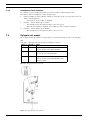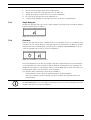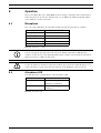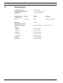
1
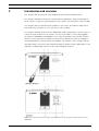
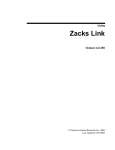
DCN-D Conference Delegate Units
DCN-DS/L, DCN-DCS, DCN-DV, DCN-DVCS
en
Installation and Operation manual
DCN-D Conference Delegate Units
Table of Contents | en
3
Table of Contents
1
Safety
5
2
About this manual
6
2.1
Digital document
6
2.2
Alerts and notice signs
6
3
Introduction and overview
7
4
Planning and design
11
4.1
Limits
11
4.1.1
Power consumption
11
5
Installation
12
5.1
Microphone buttons
12
5.1.1
Remove the microphone button
12
5.1.2
Install the priority and microphone button
13
5.2
Installation to a flat surface
13
6
Connection
14
7
Configuration
15
7.1
Initialization
15
7.2
De-initialization
15
7.3
Internal settings
16
7.3.1
Microphone sensitivity
17
7.3.2
Channel/volume restore function
17
7.3.3
Headphones level reduction
18
7.4
Delegate unit modes
18
7.4.1
Single delegate
19
7.4.2
Chairman
19
7.4.3
Single delegate with auxiliary control
20
8
Operation
21
8.1
Microphone
21
8.2
Attendance LED
21
9
Troubleshooting
22
9.1
Delegate Unit
22
10
Maintenance
23
10.1
Cleaning
23
10.2
Storage
23
Bosch Security Systems B.V.
Installation and Operation manual
F.01U.265.631 | V1.0 | 2012.03
4
11
en | Table of Contents
DCN-D Conference Delegate Units
Technical Data
F.01U.265.631 | V1.0 | 2012.03
24
Installation and Operation manual
Bosch Security Systems B.V.
DCN-D Conference Delegate Units
1
Safety | en
5
Safety
Please read the Important Safety Instructions before you install or operate the delegate units
and the DCN System.
The Important Safety Instructions are supplied together with the central control unit.
Bosch Security Systems B.V.
Installation and Operation manual
F.01U.265.631 | V1.0 | 2012.03
6
2
en | About this manual
DCN-D Conference Delegate Units
About this manual
The Installation and Operation manual gives installers and operators the necessary data to
install, configure, operate and maintain the following delegate units:
–
DCN-DS-xx (Delegate unit with fixed short stem microphone).
–
DCN-DL-xx (Delegate unit with fixed long stem microphone).
–
DCN-DCS-xx (Delegate unit with channel selector).
–
DCN-DV-xx (Delegate unit with voting).
–
DCN-DCSV-xx (Delegate unit with channel selector and voting).
-xx stands for the region version (e.g. CN is China version).
NOTICE!
This manual is an addendum to the DCN system Installation and Operation manual. Where
necessary, references will be made to the DCN system Installation and Operation manual.
All dimensions, specifications and images are subject to change without prior notice.
2.1
Digital document
This installation and operation manual is also available as a digital document in the Adobe
Portable Document Format (PDF).
When the PDF refers to a location that contains more data, click the text. The text contains
hyperlinks.
Refer to the product related information on www.boschsecuritysystems.com.
2.2
Alerts and notice signs
Three types of alerts can be used in this manual. The alert type is closely related to the effect
that may be caused if it is not observed. These alerts - from least severe effect to most severe
effect - are:
NOTICE!
Alert containing additional information. Usually, not observing a ‘notice’ does not result in
damage to the equipment or personal injuries.
CAUTION!
The equipment or the property can be damaged, or persons can be lightly injured if the alert is
not observed.
WARNING!
The equipment or the property can be seriously damaged, or persons can be severely injured
if the alert is not observed.
F.01U.265.631 | V1.0 | 2012.03
Installation and Operation manual
Bosch Security Systems B.V.
DCN-D Conference Delegate Units
3
Introduction and overview | en
7
Introduction and overview
The delegate units are part of the Bosch Digital Congress Network (DCN) system.
The delegate unit with fixed short or long microphone (DCN-DS/L) enables participants to
speak, register a request-to-speak and listen to the speaker. The microphone stem is flexible.
The delegate units accommodate two headphone connections. The built-in loudspeaker is
muted when the microphone is on to prevent acoustic feedback.
The delegate unit with channel selector (DCN-DCS) enables participants to speak, register a
request-to-speak and listen to the speaker. A socket is provided to connect the pluggable
microphones (DCN-MICS and DCN-MICL, to be ordered separately). The unit has a built-in
channel selector that makes it suitable for discussions in which more than one language is
used and simultaneous interpretations are available. The channel selector includes two up
and down channel select keys and a display showing the number and the abbreviation of the
languages, enabling rapid selection of the required language channel.
Figure 3.1 Top view of the basic delegate unit (DCN-DS/L) and the delegate unit with channel selector
(DCN-DCS)
Bosch Security Systems B.V.
Installation and Operation manual
F.01U.265.631 | V1.0 | 2012.03
8
en | Introduction and overview
DCN-D Conference Delegate Units
The delegate unit with voting (DCN-DV) and channel selector (DCN-DVCS) enables
participants to speak, register a request-to-speak, listen to the speaker and vote. A socket is
provided to connect the pluggable microphones (DCN-MICS and DCN-MICL, to be ordered
separately). The unit has five voting buttons for all types of voting. The yellow indicators
above the voting buttons are used to prompt users to register their presence, to start voting
and to confirm their vote. When the unit’s attendance LED is yellow, it indicates the delegate
is present.
Besides the voting function, the unit (DCN-DVCS) has a built-in channel selector, which makes
it suitable for discussions in which more than one language is used and simultaneous
interpretations are available. The channel selector includes up and down channel select keys
and a display showing the number and the abbreviation of the languages, enabling rapid
selection of the required language channel.
Figure 3.2 Top view of the delegate unit with voting (DCN-DV) and with channel selector (DCN-DVCS)
F.01U.265.631 | V1.0 | 2012.03
Installation and Operation manual
Bosch Security Systems B.V.
DCN-D Conference Delegate Units
Introduction and overview | en
9
The top side of the delegate unit contains:
1.
Microphone socket - Connects a pluggable microphone (DCN-MICL or DCN-MICS) to the
delegate unit.
NOTICE!
A DCN-MICL or DCN-MICS pluggable microphone cannot used with the DCN-DS and DCN-DL
delegate units. The DCN-DS and DCN-DL delegate units have fixed microphones.
2.
Loudspeaker - Gives the audio signal from the floor to the delegate or the chairman unit.
–
The loudspeaker signal is muted when the microphone is enabled.
3.
Volume buttons - Headphone output signal level adjustment.
4.
Channel selector display - Shows the number of the language channel and abbreviation
of the current headphone audio signal.
–
When the display shows FLR, the floor audio signal is on the headphones.
NOTICE!
Change the type of language abbreviation with menu e of the installation menu of the
interpreter desk.
5.
Channel selector buttons - Select the channel that is sent to the headphones.
6.
Microphone buttons - Enable or disable the microphone.
–
Each microphone button has a LED that shows the condition of the microphone.
–
The mode of the delegate unit gives the type and number of microphone buttons
which must be installed in the delegate unit.
7.
Voting buttons - Operate the delegate unit. Each voting button has a yellow LED. The
LED adjacent to voting button 1 is the attendance LED.
The left and right side of the delegate unit contains:
8.
Headphones socket - Headphone connection.
Figure 3.3 Delegate unit side views
Bosch Security Systems B.V.
Installation and Operation manual
F.01U.265.631 | V1.0 | 2012.03
10
en | Introduction and overview
DCN-D Conference Delegate Units
The rear side of the delegate unit contains:
9.
DCN cable - Connects the delegate unit to the DCN system.
10. DCN socket - Makes a loop-through in the DCN system with the delegate unit.
Figure 3.4 Delegate unit rear view
The bottom side of the delegate unit contains:
11. Screw holes - Attach the delegate unit to a flat surface.
12. Configuration switches - Configuration of the delegate unit and sets the mode of the
delegate unit.
13. De-init switch - Erases the address of the delegate unit.
–
All LEDs on the delegate unit are on when the delegate unit does not have an
address.
Figure 3.5 Delegate unit bottom view
F.01U.265.631 | V1.0 | 2012.03
Installation and Operation manual
Bosch Security Systems B.V.
DCN-D Conference Delegate Units
4
Planning and design | en
11
Planning and design
The planning and design section tells how to design the delegate units within the DCN system,
and gives necessary data to understand the limitations.
4.1
Limits
The delegate units make part of the, so-called, active devices in the DCN system. In total, 245
active devices can be used within a DCN system. Make sure the limits are not exceeded when
you design the DCN system. In general, refer to the limitations as described within the DCN
system Installation and Operation manual.
4.1.1
Power consumption
The following table shows the power consumption of each delegate unit type used in the DCN
system.
Delegate unit
Watt
DCN-DS
2.75
DCN-DL
2.75
DCN-CS
2.9
DCN-DV
3.05
DCN-DVCS
3.20
Table 4.1 Power consumption
Bosch Security Systems B.V.
Installation and Operation manual
F.01U.265.631 | V1.0 | 2012.03
12
en | Installation
5
DCN-D Conference Delegate Units
Installation
Default, the delegate unit comes in the single delegate mode and has the microphone button
installed. Read the Section 7 Configuration first, when you want to change the default delegate
settings and the delegate mode.
Figure 5.1 Default microphone button
5.1
Microphone buttons
The mode of the delegate unit indicates the type and number of microphone buttons that
must be installed. Refer to Section 7 Configuration.
NOTICE!
Before you install the microphone buttons, make sure that the delegate unit operates
correctly. Defective delegate units are always replaced with a delegate unit that contains the
default microphone button.
5.1.1
Remove the microphone button
1.
To remove the microphone button (1), push the button tool trough the bottom side holes
as indicated.
–
The tool comes with the DCN-DBCM button (2) set (to be ordered separately).
Figure 5.2 Remove the microphone button (1)
F.01U.265.631 | V1.0 | 2012.03
Installation and Operation manual
Bosch Security Systems B.V.
DCN-D Conference Delegate Units
5.1.2
Installation | en
13
Install the priority and microphone button
1.
Push the buttons (2) in the microphone button holes as indicated.
–
The DCN-DBCM button set has to be ordered separately.
Figure 5.3 Installation of the delegate microphone buttons
5.2
Installation to a flat surface
When you attach the delegate unit to a flat surface, put screws with a maximum length of 8
mm in the screw holes (11). The distance between the centres of the screw holes is 34 mm.
Figure 5.4 Installation to a flat surface
Bosch Security Systems B.V.
Installation and Operation manual
F.01U.265.631 | V1.0 | 2012.03
14
6
en | Connection
DCN-D Conference Delegate Units
Connection
1.
Connect the delegate unit to the DCN system with the delegate unit cable (9).
–
2.
Use the DCN socket (10) to make a loop-through with the delegate unit.
Use the cable-to-unit clamp to lock the DCN cable to the delegate unit:
–
Put cable-to-unit clamp on the cable connector (55°~ 60° position).
–
DCN-DISCLM cable-to-unit clamp to be ordered separately.
3.
Plug cable and clamp into the unit:
4.
Clockwise rotate clamp and make clamp snap into the locking hole of the rear panel:
F.01U.265.631 | V1.0 | 2012.03
Installation and Operation manual
Bosch Security Systems B.V.
DCN-D Conference Delegate Units
7
Configuration | en
15
Configuration
To function, each delegate unit in the DCN System must have an address. The central control
unit cannot send data to a delegate unit that does not have an address. Addressing of
delegate units in the DCN system is called, initialization. During the initialization process, the
central control unit gives an address to each delegate unit.
7.1
Initialization
NOTICE!
The central control unit cannot give addresses to more than one delegate unit at the same
time. Therefore, do not push more than one microphone button at the same time.
1.
All LED’s, including the microphone LED, of the delegate unit to be initialized must be
ON.
2.
Push the microphone button (6):
–
7.2
All LED’s OFF: delegate unit is addressed.
De-initialization
1.
2.
All LED’s of the delegate unit to be de-initialized are OFF.
Push the de-initialization switch (13) on the bottom side of the delegate unit for less than
half a second to erase the address:
–
All LEDs of the delegate unit are ON.
–
The microphone LED (red) is ON.
CAUTION!
Do not use a sharp object, otherwise you might damage the de-initialization switch. Use a
paperclip or similar device to push the de-initialization switch.
Figure 7.1 De-initialization switch
Bosch Security Systems B.V.
Installation and Operation manual
F.01U.265.631 | V1.0 | 2012.03
16
7.3
en | Configuration
DCN-D Conference Delegate Units
Internal settings
The internal settings switches I and II (12) are located at the bottom side of the delegate unit.
Switch: I
Switch: II
Internal settings
2
1
Microphone sensitivity. Default: 0 dB.
Refer to Section 7.3.1 Microphone sensitivity.
2
2
Channel/volume restore function. Default: disabled.
Refer to Section 7.3.2 Channel/volume restore function.
2
3
Headphones level reduction. Default: disabled.
Refer to Section 7.3.3 Headphones level reduction.
Table 7.1
Internal settings
Figure 7.2 Internal settings switches
F.01U.265.631 | V1.0 | 2012.03
Installation and Operation manual
Bosch Security Systems B.V.
DCN-D Conference Delegate Units
7.3.1
Configuration | en
17
Microphone sensitivity
1.
Put the microphone sensitivity switches I and II (12) in the correct position (refer to
Table 7.1 and Figure 7.2):
–
The microphone sensitivity can be adjust between -2 dB and 2 dB.
2.
Push the > volume button (3) to increase the microphone sensitivity with 0.5 dB.
3.
Push the < volume button (3) to decrease the microphone sensitivity with -0.5 dB.
The color of microphone button LED indicates the microphone sensitivity:
Value in dB
Color of microphone button LED
-2.0
Red
-1.5
Off
-1.0
Orange
-0.5
Off
0.0
Yellow
0.5
Off
1.0
Light Green
1.5
Off
2.0
Green
Table 7.2 Microphone sensitivity adjustment indication
7.3.2
Channel/volume restore function
For example, you can enable this function in discussions in which all delegates and chairman
have a fixed seat number or delegate unit:
1.
Put the channel/volume restore function switches I and II (12) in the correct position
(refer to Table 7.1 and Figure 7.2):
–
2.
3.
Bosch Security Systems B.V.
The function can be enable or disabled.
Push the > volume button (3) to enable:
–
The microphone LED above the microphone button come on as green.
–
The last known channel and volume level is automatically set.
Push the < volume (3) button to disable:
–
The LED above the microphone button come on as red.
–
The channel 0 (floor) is automatically set.
–
The volume is automatically set to -18 dB.
Installation and Operation manual
F.01U.265.631 | V1.0 | 2012.03
18
en | Configuration
7.3.3
DCN-D Conference Delegate Units
Headphones level reduction
For example, you can enable this function to avoid acoustic feedback between the
microphone and the headphones of the delegate unit:
1.
Put the headphones level reduction switches I and II (12) in the correct position (refer to
Table 7.1 and Figure 7.2):
–
2.
3.
–
The LED above the microphone button come on as green.
–
When the microphone is enabled, the headphones level reduction is 18 dB.
Push the < volume button (3) to disable:
–
7.4
The function can be enable or disabled.
Push the > volume button (3) to enable:
The LED above the microphone button come on as red.
Delegate unit modes
The delegate unit mode switches I and II (12) are located at the bottom side of the delegate
unit.
Each type of delegate unit can operate in a number of modes:
Switch: I Switch: II
Mode
1
Single delegate
1
Refer to Section 7.4.1 Single delegate.
1
3
Chairman
Refer to Section 7.4.2 Chairman.
3
3
Single delegate with auxiliary control
Refer to Section 7.4.3 Single delegate with
auxiliary control.
Table 7.3
Delegate unit mode overview
Figure 7.3 Delegate unit mode switches
F.01U.265.631 | V1.0 | 2012.03
Installation and Operation manual
Bosch Security Systems B.V.
DCN-D Conference Delegate Units
7.4.1
Configuration | en
1.
Disconnect the delegate unit from the DCN system.
2.
Change the mode of the delegate unit (refer to Table 7.3).
3.
Change the button, if required refer to Section 5 Installation.
4.
Re-connect the delegate unit to the DCN system.
5.
If required, (de-)initialize the delegate unit (refer to Section 7.1 Initialization).
19
Single delegate
Default, the delegate unit comes in the single delegate mode and has the default microphone
button installed. Refer to Table 7.3.
Figure 7.4 Default microphone button
7.4.2
Chairman
When the delegate unit is in the chairman mode, it is a chairman device for 1 chairman (refer
to Table 7.3). You can put all types of delegate units in the chairman mode. When you put the
delegate unit in the chairman mode, you also have to install the DCN-DBCM buttons (to be
ordered separately). Refer also to Section 5 Installation.
Figure 7.5 DCN-DBCM microphone buttons
The functional difference between a delegate unit and a chairman unit is the priority button
on the left hand side of the microphone button. With the priority button, the chairman can
disable the microphones of all delegate units used in the DCN system. At the same time, the
priority button enables the microphone of the chairman.
The delegate unit in chairman mode has the possibility to:
–
Play an attention chime when the chairman pushes the priority button.
–
Erase the request-to-speak list and the speakers list when the chairman pushes the
priority button.
NOTICE!
The DCN-DBCM button set comes with a tool that you can use to remove the buttons from the
delegate unit. Refer to Section 5 Installation.
Bosch Security Systems B.V.
Installation and Operation manual
F.01U.265.631 | V1.0 | 2012.03
20
en | Configuration
7.4.3
DCN-D Conference Delegate Units
Single delegate with auxiliary control
When the delegate unit is in the single delegate with auxiliary control mode, it is a delegate
device for 1 delegate (refer to Table 7.3). The delegate can use the left hand side microphone
button as an auxiliary button. For example, to activate an indicator.
NOTICE!
When the delegate pushes the auxiliary button, the auxiliary button makes an event. Use the
DCN Open Interface to program the actions that must be started by the event. Refer to the
applicable DCN software user manual for instructions that tell you how to program the Open
Interface.
The following types of delegate units can be used in the single delegate with auxiliary control
mode:
–
DCN-DV
–
DCN-DVCS
When you put the delegate unit in the single delegate with auxiliary control mode, you have to
install two microphone buttons. For example, you can use the DCN-DBCM buttons (to be
ordered separately). Refer also to Section 5 Installation.
CAUTION!
The DCN-DS/L and DCN-DCS delegate units do not support the single delegate with auxiliary
control mode. When this mode is set, the delegate unit will be operate as single user.
F.01U.265.631 | V1.0 | 2012.03
Installation and Operation manual
Bosch Security Systems B.V.
DCN-D Conference Delegate Units
8
Operation | en
21
Operation
Refer to the Quick Reference Card (QRC) of the used type of delegate unit for instructions
that tell you how to operate the delegate unit. See for QRC’s the DCN system DVD, which
comes with the central control unit.
8.1
Microphone
The color of the LED above the microphone button shows the microphone condition.
LED color
Condition
Red (on)
Microphone enabled
Red (flashing)
Last minute of speech time
Green (on)
Request-to-speak
Green (flashing)
First in request-to-speak list
Yellow (on)
VIP mode
Table 8.1 Microphone condition
NOTICE!
You can only put the delegate unit in the VIP mode with the Microphone Management
software module. Refer to the applicable DCN system software user manual for instructions
that tell you how to enable the VIP mode.
CAUTION!
For the microphones it must be avoided to bend the gooseneck more than 90 degrees or to
rotate a (bent) gooseneck. This will cause damage to the windings of the gooseneck.
8.2
Attendance LED
The LED adjacent to voting button 1 is the attendance LED.
Attendance LED
Condition
Yellow (flashing)
The system requests
attendance registration.
Yellow (on)
The attendance registration is
confirmed.
Table 8.2 Attendance LED
Bosch Security Systems B.V.
Installation and Operation manual
F.01U.265.631 | V1.0 | 2012.03
22
en | Troubleshooting
DCN-D Conference Delegate Units
9
Troubleshooting
9.1
Delegate Unit
Problem
Possible cause
–
–
Not possible to initialize delegate Units.
The DCN signal is re-generated too
many times.
–
The trunk is too long.
–
The DCN signal is not re-generated
each 100 m.
Refer to the Section 4 Planning and design
and Section 7 Configuration.
–
Depending on menu setting 8L (CCU), at
Units have the same address. Make sure
two or more delegate units the microphone that each active device in the DCN system
–
indicator ring is flashing or continues red.
has a unique address.
The LEDs of the microphone buttons are
Refer to Section 4 Planning and design and
off.
Section 7 Configuration.
Delegate unit fully operational but no audio The audio routing mode of the central
to the loudspeaker or headphones.
control unit is Insertion and you did not
connect a device between audio input 2
and audio output 2 of the central control
unit
Refer to the CCU sections of the DCN
system installation and operating manual.
–
Although the system powers the trunks,
The DCN contains a defective (extension)
delegate units are not operational.
cable. Find the defective (extension) cable
and replace it. The defective (extension)
cable can be anywhere in the DCN system.
–
A delegate unit does not operate as
The delegate unit is not in the correct
expected.
mode.
Refer to Section 7.4 Delegate unit modes.
F.01U.265.631 | V1.0 | 2012.03
Installation and Operation manual
Bosch Security Systems B.V.
DCN-D Conference Delegate Units
Maintenance | en
10
Maintenance
10.1
Cleaning
23
CAUTION!
Do not use alcohol, ammonia or petroleum solvents or abrasive cleaners to clean the delegate
units.
10.2
1.
Disconnect the delegate unit from the DCN system, if you want to clean it.
2.
Use a soft cloth that is not fully moist with a weak soap and water solution.
3.
Let the delegate unit fully dry before you install it again.
Storage
1.
Bosch Security Systems B.V.
Keep the delegate units in a clean and dry area with a sufficient airflow.
Installation and Operation manual
F.01U.265.631 | V1.0 | 2012.03
24
11
en | Technical Data
DCN-D Conference Delegate Units
Technical Data
Frequency response
30 Hz - 20 kHz
Headphone load impedance
> 32 ohm and < 1k Ohm
Output power
2 x 15 mW/32 Ohm
Headphone plug
Function
Nominal
Maximum
Headphones
3 dBV
6 dBV (mute, 0 dB)
or socket (2x)
3.5 mm
Mounting
Tabletop
Dimensions (H x W x D)
(without microphone)
60 x 210 x 140 mm (2.36 x 8.27 x 5.51 in)
Weight
- DCN-DS-xx
1.2 kg (2.65 lb)
- DCN-DL-xx
1.2 kg (2.65 lb)
- DCN-CS-xx
1.15 kg (2.54 lb)
- DCN-DV-xx
1.15 kg (2.54 lb)
- DCN-DVCS-xx
1.15 kg (2.54 lb)
Color top
Black (RAL 9017)
Color rear
Silver (RAL 9006)
F.01U.265.631 | V1.0 | 2012.03
Installation and Operation manual
Bosch Security Systems B.V.
Bosch Security Systems B.V.
Kapittelweg 10
4800 RA Breda
The Netherlands
www.boschsecurity.com
© Bosch Security Systems B.V., 2012