1
HC15
Siemens Cellular Engine
Version:
DocId:
01.001
HC15_ATC_V01.001
AT Command Set
s
HC15 AT Command Set
s
Document Name:
HC15 AT Command Set
Version:
01.001
Date:
February 16, 2007
DocId:
HC15_ATC_V01.001
Status
Confidential / Released
General Notes
Product is deemed accepted by recipient and is provided without interface to recipient’s products. The documentation and/or product are provided for testing, evaluation, integration and information purposes. The documentation and/or product are provided on an “as is” basis only and may contain deficiencies or inadequacies. The
documentation and/or product are provided without warranty of any kind, express or implied. To the maximum
extent permitted by applicable law, Siemens further disclaims all warranties, including without limitation any implied warranties of merchantability, completeness, fitness for a particular purpose and non-infringement of thirdparty rights. The entire risk arising out of the use or performance of the product and documentation remains with
recipient. This product is not intended for use in life support appliances, devices or systems where a malfunction
of the product can reasonably be expected to result in personal injury. Applications incorporating the described
product must be designed to be in accordance with the technical specifications provided in these guidelines. Failure to comply with any of the required procedures can result in malfunctions or serious discrepancies in results.
Furthermore, all safety instructions regarding the use of mobile technical systems, including GSM products,
which also apply to cellular phones must be followed. Siemens or its suppliers shall, regardless of any legal theory upon which the claim is based, not be liable for any consequential, incidental, direct, indirect, punitive or other
damages whatsoever (including, without limitation, damages for loss of business profits, business interruption,
loss of business information or data, or other pecuniary loss) arising out the use of or inability to use the documentation and/or product, even if Siemens has been advised of the possibility of such damages. The foregoing
limitations of liability shall not apply in case of mandatory liability, e.g. under the German Product Liability Act, in
case of intent, gross negligence, injury of life, body or health, or breach of a condition which goes to the root of
the contract. However, claims for damages arising from a breach of a condition, which goes to the root of the
contract, shall be limited to the foreseeable damage, which is intrinsic to the contract, unless caused by intent or
gross negligence or based on liability for injury of life, body or health. The above provision does not imply a
change on the burden of proof to the detriment of the recipient. Subject to change without notice at any time. The
interpretation of this general note shall be governed and construed according to German law without reference
to any other substantive law.
Copyright
Transmittal, reproduction, dissemination and/or editing of this document as well as utilization of its contents and
communication thereof to others without express authorization are prohibited. Offenders will be held liable for
payment of damages. All rights created by patent grant or registration of a utility model or design patent are reserved.
Copyright © Siemens AG 2007
HC15_ATC_V01.001
Confidential / Released
Page 2 of 234
2/16/07
HC15 AT Command Set
s
Contents
Contents
1.
Introduction.............................................................................................................................................. 9
1.1 Scope of the document ................................................................................................................... 9
1.2 Related documents ....................................................................................................................... 10
1.3 Document Conventions ................................................................................................................. 11
1.3.1
Quick Reference Table .................................................................................................. 11
1.3.2
Superscript Notation for Parameters And Values .......................................................... 11
1.4 HC15 AT Command Interpreter .................................................................................................... 13
1.5 AT Command Syntax .................................................................................................................... 14
1.5.1
Using Parameters .......................................................................................................... 14
1.6 Supported character sets .............................................................................................................. 15
1.6.1
GSM alphabet tables and UCS2 character values ........................................................ 17
1.6.2
UCS2 and GSM data coding and conversion for SMS text mode ................................ 19
1.6.2.1 Implementing output of SIM data to Terminal (direction TA to TE) ................................ 19
1.6.2.2 Implementing input of Terminal data to SIM (direction TE to TA)................................... 20
1.7 Communication between Customer Application and HC15 .......................................................... 21
1.8 Unsolicited Result Code Presentation........................................................................................... 22
1.8.1
Common URCs.............................................................................................................. 23
1.9 Errors and Messages .................................................................................................................... 24
2.
Configuration Commands..................................................................................................................... 25
2.1 AT&F Set all current parameters to manufacturer defaults ......................................................... 25
2.2 AT&V Display current configuration ............................................................................................ 26
2.3 ATQ Set result code presentation mode ..................................................................................... 27
2.4 ATV Set result code format mode ............................................................................................... 28
2.4.1
Verbose and numeric result codes ................................................................................ 28
2.5 ATX Set CONNECT result code format ...................................................................................... 29
2.6 ATZ Reset all current parameters to the default configuration.................................................... 30
2.7 AT+CFUN Set phone functionality .............................................................................................. 31
2.8 AT+CMEE Mobile Equipment Error Message Format ................................................................ 32
2.8.1
CME/CMS Error Code Overview ................................................................................... 33
2.9 AT+CSCS Select TE character set ............................................................................................. 36
2.10 AT+GCAP Request complete TA capabilities list........................................................................ 37
2.11 AT^SCFG Extended Configuration Settings ............................................................................... 38
2.12 AT^SMSO Switch off mobile station............................................................................................ 40
2.13 AT^SUSB USB Configuration ..................................................................................................... 41
3.
Status Control Commands ................................................................................................................... 45
3.1 AT+CEER Extended Error Report............................................................................................... 45
3.1.1
List of status codes for the extended error report .......................................................... 46
3.2 AT+CPAS Mobile equipment activity status ................................................................................ 51
3.3 AT+WS46 Select wireless network ............................................................................................. 52
4.
Serial Interface Control Commands..................................................................................................... 53
4.1 AT^SQPORT Query Port Type ................................................................................................... 53
4.2 AT&C Set Data Carrier Detect (DCD) Line mode ....................................................................... 54
4.3 AT&D Set circuit Data Terminal Ready (DTR) function mode..................................................... 55
HC15_ATC_V01.001
Confidential / Released
Page 3 of 234
2/16/07
HC15 AT Command Set
Contents
s
4.4
ATE Enable command echo........................................................................................................ 56
5.
Security Commands .............................................................................................................................. 57
5.1 AT+CLCK Facility lock ................................................................................................................ 57
5.2 AT+CPIN PIN Authentication ...................................................................................................... 61
5.2.1
What to do if PIN or password authentication fails? ...................................................... 63
5.3 AT+CPWD Change Password .................................................................................................... 64
5.4 AT^SCSL Customer SIM Lock .................................................................................................... 66
6.
Identification Commands...................................................................................................................... 68
6.1 ATI Display product identification information ............................................................................. 68
6.2 AT+CGMI Request manufacturer identification........................................................................... 69
6.3 AT+GMI Request manufacturer identification ............................................................................. 69
6.4 AT+CGMM Request model identification .................................................................................... 70
6.5 AT+GMM Request model identification....................................................................................... 70
6.6 AT+CGMR Request revision identification of software status..................................................... 71
6.7 AT+GMR Request revision identification of software status ....................................................... 71
6.8 AT+CGSN Request International Mobile Equipment Identity (IMEI) ........................................... 72
6.9 AT+GSN Request International Mobile Equipment Identity (IMEI) ............................................. 72
6.10 AT+CIMI Request International Mobile Subscriber Identity (IMSI).............................................. 73
7.
Call related Commands......................................................................................................................... 74
7.1 ATA Answer a call ....................................................................................................................... 74
7.2 ATD Mobile originated call to specified number .......................................................................... 75
7.3 ATD><mem><n> Mobile originated call using specific memory and index number ................... 77
7.4 ATD><n> Mobile originated call from active memory using index number ................................. 79
7.5 ATD><str> Mobile originated call from active memory using corresponding field ...................... 80
7.6 ATH Disconnect existing data connection................................................................................... 81
7.7 AT+CHUP Hang up call .............................................................................................................. 82
7.8 ATS0 Set number of rings before automatically answering a call ............................................... 83
7.9 ATS6 Set pause before blind dialing ........................................................................................... 84
7.10 ATS7 Set number of seconds to wait for connection completion ................................................ 85
7.11 ATS8 Set number of seconds to wait for comma dialing modifier............................................... 86
7.12 ATS10 Set disconnect delay after indicating the absence of data carrier ................................... 87
7.13 ATO Switch from command mode to data mode ........................................................................ 88
7.14 +++ Switch from data mode to command mode ......................................................................... 89
7.15 AT+CLCC List current calls of ME .............................................................................................. 90
7.16 AT+CR Service reporting control ................................................................................................ 92
7.17 AT+CRC Set Cellular Result Codes for incoming call indication ................................................ 93
7.18 AT+CBST Select bearer service type ......................................................................................... 95
7.18.1
Parameter configurations supported by AT+CBST........................................................ 96
7.19 AT+CRLP Select radio link protocol parameters for originated non-transparent data calls ........ 97
7.20 ATP Select pulse dialing ............................................................................................................. 99
7.21 ATT Select tone dialing ............................................................................................................... 99
7.22 AT+ES Synchronous Data Mode Configuration ........................................................................ 100
7.23 AT+ESA Synchronous access mode configuration................................................................... 101
7.24 AT+CSTA Select type of address ............................................................................................. 103
8.
Network Service Commands .............................................................................................................. 104
8.1 AT+COPN Read operator names ............................................................................................. 104
8.2 AT+COPS Operator Selection .................................................................................................. 105
HC15_ATC_V01.001
Confidential / Released
Page 4 of 234
2/16/07
HC15 AT Command Set
Contents
s
8.3
8.4
AT+CREG Network registration ................................................................................................ 108
AT+CSQ Signal quality ............................................................................................................. 110
9.
Supplementary Service Commands .................................................................................................. 111
9.1 AT+CACM Accumulated call meter (ACM) reset or query ........................................................ 111
9.2 AT+CAMM Accumulated call meter maximum (ACMmax) set or query.................................... 112
9.3 AT+CAOC Advice of Charge information .................................................................................. 113
9.4 AT+CCFC Call forwarding number and conditions control ....................................................... 115
9.5 AT+CCWA Call Waiting ............................................................................................................ 119
9.6 AT+CHLD Call Hold and Multiparty........................................................................................... 122
9.7 AT+CLIP Calling Line Identification Presentation ..................................................................... 125
9.8 AT+COLP Connected Line Identification Presentation ............................................................. 127
9.9 AT+CPUC Price per unit and currency table............................................................................. 129
9.10 AT+CSSN Supplementary service notifications ........................................................................ 130
10.
GPRS Commands ................................................................................................................................ 132
10.1 AT+CGATT PS attach or detach ............................................................................................... 132
10.2 AT+CGACT PDP context activate or deactivate ....................................................................... 133
10.3 AT+CGDATA Enter data state .................................................................................................. 135
10.3.1
Automatic deactivation of PDP context during dial-up PPP......................................... 136
10.4 AT+CGDCONT Define PDP Context ........................................................................................ 137
10.5 AT+CGPADDR Show PDP address ......................................................................................... 139
10.6 AT+CGQMIN Quality of Service Profile (Minimum acceptable) ................................................ 140
10.7 AT+CGEQMIN 3G Quality of Service Profile (Minimum acceptable) ........................................ 143
10.8 AT+CGREG GPRS Network Registration Status...................................................................... 147
10.9 AT+CGQREQ Quality of Service Profile (Requested) .............................................................. 149
10.10 AT+CGEQREQ 3G Quality of Service Profile (Requested) ...................................................... 153
10.11 AT+CGSMS Select service for MO SMS messages ................................................................. 157
10.12 AT+CGTFT Traffic Flow Template ............................................................................................ 158
10.13 ATD*99# Request GPRS service.............................................................................................. 161
10.14 AT^SGAUTH Set type of authentication for PDP-IP connections ............................................. 162
11.
Short Message Service (SMS) Commands........................................................................................ 164
11.1 SMS parameters ......................................................................................................................... 164
11.2 AT+CMGC Send an SMS command......................................................................................... 168
11.3 AT+CMGD Delete short message............................................................................................. 169
11.4 AT+CMGF Select SMS message format .................................................................................. 170
11.5 AT+CMGL List SMS messages from preferred store................................................................ 171
11.6 AT+CMGR Read SMS messages ............................................................................................. 173
11.7 AT+CMGS Send Short Message .............................................................................................. 175
11.8 AT+CMGW Write Short Messages to Memory ......................................................................... 176
11.9 AT+CMMS More Messages to Send......................................................................................... 177
11.10 AT+CMSS Send short messages from storage ........................................................................ 178
11.11 AT+CNMA New Message Acknowledgement to ME/TE, only phase 2+ .................................. 179
11.12 AT+CNMI New short Message Indication ................................................................................. 180
11.13 AT+CPMS Preferred SMS message storage ............................................................................ 183
11.14 AT+CSCA SMS Service Center Address .................................................................................. 185
11.15 AT+CSCB Select Cell Broadcast Message Indication .............................................................. 186
11.16 AT+CSMP Set SMS text Mode Parameters.............................................................................. 188
11.17 AT+CSMS Select Message Service.......................................................................................... 190
HC15_ATC_V01.001
Confidential / Released
Page 5 of 234
2/16/07
HC15 AT Command Set
s
Contents
12.
SIM related Commands ....................................................................................................................... 192
12.1 AT+CRSM Restricted SIM Access ............................................................................................ 192
12.2 AT+CSIM Generic SIM Access ................................................................................................. 194
12.3 AT^SCKS Query SIM and Chip Card Holder Status ................................................................. 196
13.
Phonebook Commands....................................................................................................................... 198
13.1 AT+CNUM Read own numbers................................................................................................. 198
13.2 AT+CPBF Find phonebook entries ........................................................................................... 199
13.3 AT+CPBR Read from phonebook ............................................................................................. 202
13.4 AT+CPBS Select phonebook memory storage ......................................................................... 205
13.5 AT+CPBW Write into phonebook .............................................................................................. 207
14.
Audio Commands ................................................................................................................................ 210
14.1 ATL Set monitor speaker loudness ........................................................................................... 210
14.2 ATM Set monitor speaker mode................................................................................................ 210
14.3 AT+VTS DTMF and tone generation......................................................................................... 211
14.4 AT^SNFS Select audio hardware set ........................................................................................ 212
14.5 AT^SRTC Ring tone configuration ............................................................................................ 213
15.
Hardware Related Commands............................................................................................................ 214
15.1 AT^SLED LED Feature ............................................................................................................. 214
16.
Miscellaneous Commands.................................................................................................................. 216
16.1 ATS3 Set command line termination character......................................................................... 216
16.2 ATS4 Set response formatting character .................................................................................. 217
16.3 ATS5 Write command line editing character ............................................................................. 218
17.
Appendix .............................................................................................................................................. 219
17.1 Restricted access to SIM data after SIM PIN authentication....................................................... 219
17.2 Star-Hash (*#) Network Commands............................................................................................ 220
17.3 Available AT Commands and Dependency on SIM PIN ............................................................. 223
17.4 Factory Default Settings Restorable with AT&F .......................................................................... 227
17.5 Summary of Unsolicited Result Codes (URC)............................................................................. 229
17.6 AT Commands Supported Only on the Modem Interface ........................................................... 230
17.7 Alphabetical List of AT Commands ............................................................................................. 231
HC15_ATC_V01.001
Confidential / Released
Page 6 of 234
2/16/07
HC15 AT Command Set
s
List of Tables
List of Tables
Table 1.1:
Table 1.2:
Table 1.3:
Table 1.4:
Table 1.5:
Table 2.1:
Table 2.2:
Table 2.3:
Table 2.4:
Table 7.1:
Table 17.1:
Table 17.2:
Table 17.3:
Table 17.4:
Table 17.5:
Table 17.6:
Table 17.7:
Table 17.8:
Table 17.9:
Symbols used to mark the type of parameters ........................................................................... 11
Symbols used to indicate the correlations with other commands ............................................... 11
Symbols Used to Mark Different Types of Default Values of Parameters ................................. 12
Types of AT commands and responses .................................................................................... 14
Examples for character definitions depending on alphabet ........................................................ 16
General "CME ERROR" Codes (GSM 07.07) .......................................................................... 33
GPRS related "CME ERROR" Codes (GSM 07.07) ................................................................. 34
SIEMENS specific "CME ERROR" Codes ................................................................................ 34
SMS related "CMS ERROR" Codes (GSM 07.05) ................................................................... 34
Parameter configurations supported by AT+CBST...................................................................... 96
Star-Hash (*#) Command Overview ........................................................................................ 220
Abbreviations of Codes and Parameters used in Table 17.1 .................................................. 221
Star-Hash Command Response Parameters .......................................................................... 221
Star-Hash Commands for Supplementary Services ................................................................ 222
Available AT Commands and Dependency on SIM PIN........................................................... 223
Factory Default Settings Restorable with AT&F ....................................................................... 227
Summary of Unsolicited Result Codes (URC) .......................................................................... 229
AT Commands Supported Only on the Modem Interface......................................................... 230
Alphabetical List of AT Commands........................................................................................... 231
HC15_ATC_V01.001
Confidential / Released
Page 7 of 234
2/16/07
HC15 AT Command Set
s
List of Figures
List of Figures
Figure 1.1:
Figure 1.2:
Main character table of GSM 03.38 alphabet ............................................................................. 17
Extension character table of GSM 03.38 alphabet ..................................................................... 18
HC15_ATC_V01.001
Confidential / Released
Page 8 of 234
2/16/07
HC15 AT Command Set
s
1. Introduction
1.
Introduction
1.1
Scope of the document
This document presents the AT Command Set for the Siemens Cellular Engine
HC15 Release 01.001.
Before using the Cellular Engine or upgrading to a new firmware version please read the latest product information provided in the Release Notes [1].
More information is available at the Siemens Website: http://www.siemens.com/wm.
HC15_ATC_V01.001
Confidential / Released
Page 9 of 234
2/16/07
HC15 AT Command Set
s
1.2 Related documents
1.2
Related documents
[1] HC15 Release Notes, Version 01.001
[2] HC15 Hardware Interface Description, Version 01.001
[3] ISO/IEC10646: "Universal Multiple-Octet Coded Character Set (UCS)"; UCS2, 16 bit coding
[4] ITU-T Recommendation V.24: List of definitions for interchange circuits between data terminal equipment
(DTE) and data circuit-terminating equipment (DCE)
[5] ITU-T Recommendation V.250: Serial asynchronous automatic dialling and control
[6] 3GPP TS 100 918/EN 300 918 (GSM 02.04): General on supplementary services
[7] 3GPP TS 100 907 (GSM 02.30): Man-Machine Interface (MMI) of the Mobile Station (MS)
[8] 3GPP TS 23.038 (GSM 03.38): Alphabets and language specific information
[9] 3GPP TS 27.005 (GSM 07.05): Use of Data Terminal Equipment - Data Circuit terminating Equipment (DTE
- DCE) interface for Short Message Service (SMS) and Cell Broadcast Service (CBS)
[10] 3GPP TS 27.007 (GSM 07.07): AT command set for User Equipment (UE)
[11] 3GPP TS 27.060 (GSM 07.60): Mobile Station (MS) supporting Packet Switched Services
[12] 3GPP TS 51.011 (GSM 11.11): Specification of the Subscriber Identity Module - Mobile Equipment (SIM -
ME) interface
[13] ETSI 102 221: Smart cards; UICC-Terminal interface; Physical and logical characteristics
[14] 3GPP TS 31.102: 3rd Generation Partnership Project; Technical Specification Group Network and Termi-
nals; Characteristics of the USIM application
[15] 3GPP TS 11.14 (GSM 11.14): Specification of the SIM Application Toolkit for the Subscriber Identity Module
- Mobile Equipment (SIM - ME) interface
HC15_ATC_V01.001
Confidential / Released
Page 10 of 234
2/16/07
HC15 AT Command Set
s
1.3 Document Conventions
1.3
Document Conventions
Throughout the document, the GSM engines are referred to as ME (Mobile Equipment), MS (Mobile Station), TA
(Terminal Adapter), DCE (Data Communication Equipment) or facsimile DCE (FAX modem, FAX board).
To control your GSM engine you can simply send AT Commands via its serial interface. The controlling device
at the other end of the serial line is referred to as TE (Terminal Equipment), DTE (Data Terminal Equipment) or
plainly 'the application' (probably running on an embedded system).
All abbreviations and acronyms used throughout this document are based on the GSM specifications. For definitions please refer to TR 100 350 V7.0.0 (1999-08), (GSM 01.04, version 7.0.0 release 1998).
1.3.1
Quick Reference Table
Each AT command description includes a table similar to the example shown below. The table is intended as a
quick reference to indicate the following functions:
PIN:
Is the AT command PIN protected?
+
Yes
No
±
Usage is dependent on conditions specified for the command, or not all command
types are PIN protected (for example write command PIN protected, read command
not).
Note: The table provided in Section 17.3, Available AT Commands and Dependency
on SIM PIN uses the same symbols.
USB0-MDM:
Is the AT command supported on the Modem interface?
+
Yes
No
USB0-APP:
Is the AT command supported on the Application interface?
+
Yes
No
Last:
If commands are concatenated, this AT command must be the last one.
+
Yes
No
Note: See also Section 1.5, AT Command Syntax for details on concatenated AT commands.
Example:
PIN
USB0-MDM
USB0-APP
Last
-
+
+
-
1.3.2
Table 1.1:
Superscript Notation for Parameters And Values
Symbols used to mark the type of parameters
Parameter type
Meaning
<param>
(num)
Parameter value must be numeric type
<param>
(str)
Parameter value must be string type enclosed in quotation marks.
Table 1.2:
Symbols used to indicate the correlations with other commands
Parameter option
<param>
(+CSCS)
HC15_ATC_V01.001
Confidential / Released
Meaning
Parameter value has to be (is) coded according to current setting of <chset> (see
AT+CSCS for details)
Page 11 of 234
2/16/07
HC15 AT Command Set
s
1.3 Document Conventions
Table 1.3:
Symbols Used to Mark Different Types of Default Values of Parameters
Value option
Meaning
[x]
Default value: if the parameter is omitted, the value 'x' will be assumed
x
(&F)
Factory default value, will be restored to 'x' with AT&F
x
(P)
Powerup default value of a parameter which is not stored at power down
x
(D)
Delivery default value of a parameter which cannot be restored automatically
HC15_ATC_V01.001
Confidential / Released
Page 12 of 234
2/16/07
HC15 AT Command Set
s
1.4 HC15 AT Command Interpreter
1.4
HC15 AT Command Interpreter
After successful installation of the HC15 driver package, the physical USB interface of the module is represented
in the operating system by two virtual interfaces, each assigned to a virtual COM port of its own:
• Modem interface:
This interface is referred to as "Modem" if queried with AT^SQPORT. In the quick reference tables it is named
USB0-MDM. In Windows XP, it will show up as "Siemens HSDPA USB Modem" in the Windows Device Manager, under Modems. The COM port number automatically assigned by Windows during the installation can
be gathered from the Modems property page.
The modem interface is intended particularly for data transmission (HSDPA, GPRS or CSD) established over
a dial-up connection. Using AT commands on this interface is not recommended, except for data call related
commands like ATD or ATO.
URCs relevant for data calls (RING, NO CARRIER) are issued on the modem interface, all other URCs normally only on the application interface.
• Application interface:
This port is referred to as "Application" if queried with AT^SQPORT. In the quick reference tables it is named
USB0-APP. In Windows XP, it will show up as "Siemens HSDPA USB Com Port" in the Windows Device Manager, under Ports (COM&LPT), along with the COM port number automatically assigned by Windows.
The application interface is designed especially for controlling the HC15, i.e. for entering AT commands,
receiving URCs, or sending and receiving short messages. It is not intended as data interface for HSDPA,
GPRS or CSD.
Please note that URCs are normally indicated only on this interface, no matter which of the two interfaces
was used to send the AT commands for activating their presentation.
This URC management scheme is the default configuration recommended for a typical HC15 application. For
further detail on URCs please refer to Section 1.8, Unsolicited Result Code Presentation.
If you need to operate the HC15 from both interfaces at a time, bear in mind that both are handled by the same
AT command interpreter. As a result, AT commands entered on both interfaces are not executed in parallel but
sequentially, one after the other. So, an AT command issued on one interface will be buffered on this interface
to be executed after the other interface has completed processing earlier AT command(s). The buffered command string is not echoed, but will be indicated when executed.
When a dial-up connection is established over the modem interface, the application interface can be used simultaneously for any control functions. This eliminates the need for the user to enter AT commands, such as +++
and ATO, to switch back and forth between command and online mode when working on one interface only. Yet,
it should be noted that the dial-up connection disables the echo on both interfaces, due to the initialization strings
typically set by modems. The echo can be re-activated by executing ATE1.
HC15_ATC_V01.001
Confidential / Released
Page 13 of 234
2/16/07
HC15 AT Command Set
s
1.5 AT Command Syntax
1.5
AT Command Syntax
The "AT" or "at" prefix must be set at the beginning of each command line. To terminate a command line enter
<CR>. Commands are usually followed by a response that includes "<CR><LF><response><CR><LF>". Throughout this document, only the responses are presented, <CR><LF> are omitted intentionally.
Table 1.4:
AT command type
Syntax
Function
Test command
AT+CXXX=?
The mobile equipment returns the list of parameters and value
ranges set with the corresponding Write command or by internal
processes.
Read command
AT+CXXX?
This command returns the currently set value of the parameter or
parameters.
Write command
AT+CXXX=<...>
This command sets user-definable parameter values.
Exec(ution) command
AT+CXXX
The execution command reads non-variable parameters determined by internal processes in the GSM engine.
1.5.1
•
•
•
•
•
•
•
Types of AT commands and responses
Using Parameters
Optional parameters are enclosed in square brackets. If optional parameters are omitted, the current settings
are used until you change them.
Optional parameters or subparameters can be omitted unless they are followed by other parameters. If you
want to omit a parameter in the middle of a string it must be replaced by a comma. See also example 1.
A parameter value enclosed in square brackets represents the value that will be used if an optional parameter
is omitted. See also example 2.
When the parameter is a character string, e.g. <text> or <number>, the string must be enclosed in quotation
marks, e.g. "Charlie Brown" or "+49030xxxx". Symbols in quotation marks will be recognized as strings.
All spaces will be ignored when using strings without quotaton marks.
It is possible to omit the leading zeros of strings which represent numbers.
If an optional parameter of a V.250 command is omitted, its value is assumed to be 0.
Example 1: Omitting parameters in the middle of a string
AT+CCUG?
+CCUG: 1,10,1
OK
AT+CCUG=,9
OK
AT+CCUG?
+CCUG: 1,9,1
OK
HC15_ATC_V01.001
Confidential / Released
Query current setting
Set only the middle parameter
Query new setting
Page 14 of 234
2/16/07
HC15 AT Command Set
s
1.6 Supported character sets
1.6
Supported character sets
The ME supports two character sets: GSM 03.38 (7 bit, also referred to as GSM alphabet or SMS alphabet) and
UCS2 (16 bit, refer to ISO/IEC 10646). See AT+CSCS for information about selecting the character set. Character
tables can be found below.
Explanation of terms
• International Reference Alphabet (IRA)
IRA means that one byte is displayed as two characters in hexadecimal format. For example, the byte 0x36
(decimal 54) is displayed as "36" (two characters). IRA is used here for input 8-bit or 16-bit data via terminal
devices using text mode. This means only characters 'A'..F','a'..'f' and '0'..'9' are valid.
• Escape sequences
The escape sequence used within a text coded in the GSM default alphabet (0x1B) must be correctly interpreted by the TE, both for character input and output. To the module, an escape sequence appears like any
other byte received or sent.
• Terminal Adapter (TA)
TA is an equivalent to Mobile Equipment (ME) which stands for the GSM module described here. It uses GSM
default alphabet as its character set.
• Terminal Equipment (TE)
TE is the device connected to the TA via serial interface. In most cases TE is an ANSI/ASCII terminal that
does not fully support the GSM default alphabet, for example MS Hyperterminal.
• TE Character Set
The character set currently used by Terminal Equipment is selected with AT+CSCS.
• Data Coding Scheme (dcs)
DCS is part of a short message and is saved on the SIM. When writing a short message to the SIM in text
mode, the dcs stored with AT+CSMP is used and determines the coded character set.
The behavior when encountering characters that are not valid characters of the supported alphabets is undefined.
Due to the constraints described below it is recommended to prefer the USC2 alphabet in any external application.
If the GSM alphabet is selected all characters sent over the serial line (between TE and TA) are in the range from
0 to 127 (7 Bit range). CAUTION: ASCII alphabet (TE) is not GSM alphabet (TA/ME) !
Several problems resulting from the use of GSM alphabet with ASCII terminal equipment:
• "@" character with GSM alphabet value 0 is not printable by an ASCII terminal program (e.g. Microsoft©
Hyperterminal®).
• "@" character with GSM alphabet value 0 will terminate any C string! This is because the 0 is defined as C
string end tag. Therefore, the GSM Null character may cause problems on application level when using a 'C'function as "strlen()". This can be avoided if it is represented by an escape sequence as shown in the table
below.
By the way, this may be the reason why even network providers often replace "@"with "@=*" in their SIM
application.
• Other characters of the GSM alphabet are misinterpreted by an ASCII terminal program. For example, GSM
"ö" (as in "Börse") is assumed to be "|" in ASCII, thus resulting in "B|rse". This is because both alphabets mean
different characters with values hex. 7C or 00 and so on.
• In addition, decimal 17 and 19 which are used as XON/XOFF control characters when software flow control
is activated, are interpreted as normal characters in the GSM alphabet.
When you write characters differently coded in ASCII and GSM (e.g. Ä, Ö, Ü), you need to enter escape
sequences. Such a character is translated into the corresponding GSM character value and, when output later,
the GSM character value can be presented. Any ASCII terminal then will show wrong responses.
HC15_ATC_V01.001
Confidential / Released
Page 15 of 234
2/16/07
HC15 AT Command Set
s
1.6 Supported character sets
Table 1.5:
Examples for character definitions depending on alphabet
GSM 03.38
character
GSM character
hex. value
Corresponding
ASCII character
ASCII
Esc sequence
Hex Esc
sequence
Ö
5C
\
\5C
5C 35 43
"
22
"
\22
5C 32 32
@
00
NULL
\00
5C 30 30
CAUTION: Often, the editors of terminal programs do not recognize escape sequences. In this case, an escape
sequence will be handled as normal characters. The most common workaround to this problem is to write a script
which includes a decimal code instead of an escape sequence. This way you can write, for example, short messages which may contain differently coded characters.
HC15_ATC_V01.001
Confidential / Released
Page 16 of 234
2/16/07
HC15 AT Command Set
s
1.6 Supported character sets
1.6.1
GSM alphabet tables and UCS2 character values
This section provides tables for the GSM 03.38 alphabet supported by the ME. Below any GSM character find
the corresponding two byte character value of the UCS2 alphabet.
(For related mapping definition see: http://www.unicode.org/Public/MAPPINGS/ETSI/GSM0338.TXT)
Figure 1.1: Main character table of GSM 03.38 alphabet
1) This code is an escape to the following extension of the 7 bit default alphabet table.
2) This code is not a printable character and therefore not defined for the UCS2 alphabet. It shall be treated as the accompanying control character.
3) As the standard GSM alphabet does not provide a backspace functionality the HC15 is designed to use the GSM character 08 (hex 0x08) as backspace. This allows the user to easily erase the last character when using an ASCII terminal.
On the other hand, this solution requires entering the escape sequence \08 for writing the "ò" character in GSM alphabet.
HC15_ATC_V01.001
Confidential / Released
Page 17 of 234
2/16/07
HC15 AT Command Set
s
1.6 Supported character sets
Figure 1.2: Extension character table of GSM 03.38 alphabet
1) This code value is reserved for the extension to another extension table. On receipt of this code, a receiving entity shall
display a space until another extension table is defined.
2) This code represents the EURO currency symbol. The code value is the one used for the character 'e'. Therefore a receiving entity which is incapable of displaying the EURO currency symbol will display the character 'e' instead.
3) This code is defined as a Page Break character and may be used for example in compressed CBS messages. Any mobile
which does not understand the 7 bit default alphabet table extension mechanism will treat this character as Line Feed.
HC15_ATC_V01.001
Confidential / Released
Page 18 of 234
2/16/07
HC15 AT Command Set
s
1.6 Supported character sets
In the event that an MS receives a code where a symbol is not represented in Figure 1.2, Extension character
table of GSM 03.38 alphabet the MS shall display the character shown in the main default 7 bit alphabet table
(see Figure 1.1, Main character table of GSM 03.38 alphabet).
1.6.2
UCS2 and GSM data coding and conversion for SMS text mode
This section provides basic information on how to handle input and output character conversion for SMS text
mode if internal (TA) and external (TE) character representation differ, i.e. if the Data Coding Scheme and the
TE character use different coding.
1.6.2.1
Implementing output of SIM data to Terminal (direction TA to
TE)
Used character set
DCS = 7 bit
GSM
DCS = 8 bit
Data
DCS = 16 bit
UCS2
GSM
Case 1
GSM (1:1)
Case 2
8 bit to IRA (1:2)
Case 3
UCS2 to IRA (2:4)
Case 4
Case 5
GSM to IRA (1:4)
8 bit to IRA (1:4)
Note: The ratio of SIM bytes to output bytes is given in parentheses.
Case 6
UCS2 to IRA (2:4)
UCS2
Case 1
Every GSM character is sent to the TE as it is (8-bit value with highest bit set to zero).
Example: 47'H, 53'H, 4D'H → 47'H, 53'H, 4D'H, displayed as "GSM"
Case 2
Every data byte is sent to the TE as 2 IRA characters each representing a halfbyte.
Example: B8'H (184 decimal) → 42'H, 38'H, displayed as "B8"
Case 3
Every 16-bit UCS2 value is sent to the TE as 4 IRA characters.
Example: C4xA7'H (50343 decimal) → 43'H, 34'H, 41'H, 37'H, displayed as "C4A7"
Problem: An odd number of bytes leads to an error because there are always two bytes needed for each USC2
character
Case 4
Every GSM character is sent to the TE as 4 IRA characters to show UCS2 in text mode.
Example: 41'H ("A") → 30'H, 30'H, 34'H, 31'H, displayed as "0041"
Case 5
Every data byte is sent to the TE as IRA representation of UCS2 (similar to case 4).
Example: B2'H → 30'H, 30'H, 42'H, 32'H, displayed as "00B2"
Case 6
Every 16-bit value is sent to the TE as IRA representation of it. It is assumed that number of bytes is even.
Example: C3x46'H → 43'H, 33'H, 34'H, 36'H, displayed as "C346"
HC15_ATC_V01.001
Confidential / Released
Page 19 of 234
2/16/07
HC15 AT Command Set
s
1.6 Supported character sets
1.6.2.2
Implementing input of Terminal data to SIM (direction TE to TA)
Used character set
DCS = 7 bit
GSM
DCS = 8 bit
Data
DCS = 16 bit
UCS2
GSM
Case 1
GSM (1:1)
Case 2
IRA to 8 bit (2:1)
Case 3
IRA to 16 bit (4:2)
UCS2
Case 4
Case 5
Case 6
UCS2 to GSM (4:1)
UCS2 to 8 bit (4:1)
UCS2 to 16 bit (4:2)
Note: The ratio between the number of input characters and bytes stored on the SIM is given in parentheses.
Case 1
Every character is sent from TE to TA as GSM character (or ASCII with standard terminal emulation, e.g. Hyperterminal).
Character value must be in range from 0 to 127 because of 7-bit GSM alphabet.
To reach maximum SMS text length of 160 characters in 140 bytes space characters will be compressed on SIM.
This must be set using the parameter <dcs> of AT+CSMP (add 64).
Example: "ABCDEFGH" typed is sent and stored uncompressed as → 4142434445464748'H (stored compressed as 41E19058341E91'H)
Case 2
Every data byte is sent as 2 IRA characters.
Maximum text length is 280 IRA characters which will be converted into 140 bytes SMS binary user data
Example: "C8" typed is sent as 43'H, 38'H → stored as C8'H
Case 3
Every 16-bit value is sent as 4 IRA characters.
Maximum text length is 280 IRA characters which will be converted into 70 UCS2 characters (16-bit each)
Number of IRA characters must be a multiple of four because always 4 half bytes are needed for a 16-bit value
Example: "D2C8" typed is sent as 44'H, 32'H, 43'H, 38'H → stored as D2C8'H
Case 4
Every GSM character is sent as 4 IRA characters representing one UCS2 character.
Example: To store text "ABC" using UCS2 character set you have to type "004100420043".
This is sent as 30'H,30'H,34'H,31'H, 30'H,30'H,34'H,32'H, 30'H,30'H,34'H,33'H → detected as IRA representation of 3 UCS2 characters, converted to GSM character set and stored as 41'H, 42'H, 43'H.
Maximum input is 640 IRA characters repesenting 160 UCS2 characters when compression is active. These are
converted to 160 GSM 7-bit characters.
Without compression only 140 GSM characters can be stored which are put in as 560 IRA characters.
Values of UCS2 characters must be smaller than 80'H (128 decimal) to be valid GSM characters.
Number of IRA characters must be a multiple of four. Problems:
• "41" → Error, there are four IRA characters (two bytes) needed
• "0000" → Error, not an UCS2 character
• "4142" → Error, value of UCS2 character > 7F'H
• "008B" → Error, value of UCS2 character > 7F'H
This affects the maximum input length of a string)
Case 5
Every UCS2 character is sent as 4 IRA characters and is converted into two 8-bit values. This means that the
first two characters have to be '00'.
Example: UCS2 character 009F'H typed as "009F" is sent as 30'H,30'H,39'H,46'H → converted into 8-bit value
9F'H.
Maximum number of UCS2 characters is 140 which are represented by 560 IRA characters. Number of IRA characters must be a multiple of four.
Case 6
Every UCS2 character is sent as 4 IRA characters each and is converted into a 16-bit value again.
Example: UCS2 character 9F3A'H typed as "9F3A" is sent as 39'H,46'H,33'H,41'H → converted into 9F3A'H.
Maximum number of UCS2 characters is 70 which are represented by 280 IRA characters. Number of IRA characters must be a multiple of four.
Invalid UCS2 values must be prevented.
HC15_ATC_V01.001
Confidential / Released
Page 20 of 234
2/16/07
HC15 AT Command Set
1.7 Communication between Customer Application and HC15
1.7
s
Communication between Customer Application and HC15
Leaving hardware flow control unconsidered the Customer Application (TE) is coupled with the HC15 (ME) via
a receive and a transmit line.
Since both lines are driven by independent devices collisions may (and will) happen. For example, if the TE
issues an AT command the HC15 starts sending a URC. This will probably cause the TE to misinterpret of the
URC being part of the AT command's response.
To avoid this conflict the following measures must be taken:
• If an AT command is finished (with "OK" or "ERROR") the TE shall always wait at least 100 milliseconds
before sending the next one.
This gives the HC15 the opportunity to transmit pending URCs and get necessary service.
Note that some AT commands may require more delay after "OK" or "ERROR" response, refer to the following
command specifications for details.
• The TE shall communicate with the HC15 using activated echo (ATE1), i.e. the HC15 echoes characters
received from the TE.
Hence, when the TE receives the echo of the first character "A" of the AT command just sent by itself it has
control both over the receive and the transmit paths.
HC15_ATC_V01.001
Confidential / Released
Page 21 of 234
2/16/07
HC15 AT Command Set
s
1.8 Unsolicited Result Code Presentation
1.8
Unsolicited Result Code Presentation
URC stands for Unsolicited Result Code and is a report message issued by the ME without being requested by
the TE, i.e. a URC is issued automatically when a certain event occurs. Hence, a URC is not issued as part of
the response related to an executed AT command.
Typical events leading to URCs are incoming calls ("RING"), waiting calls, received short messages, network
registration etc. For most of these messages, the ME needs to be configured whether or not to send a URC.
Descriptions of these URCs are provided with the associated AT command. Only the URCs related to automatic
shutdown are not user definable. These URCs are described in Section 1.8.1, Common URCs. A summary of all
URCs can be found in Section 17.5, Summary of Unsolicited Result Codes (URC).
As specified in Section 1.4, HC15 AT Command Interpreter the modem interface is dedicated for data transmission (HSDPA, GPRS, CSD). The application interface is designed primarily for control functions. This implies that
the majority of URCs are normally issued on the application interface, no matter which of the AT interfaces was
used to send the AT command for activating their presentation. Only URCs relevant for data calls (RING, NO
CARRIER) are issued on the modem interface to ensure compatability with existing modem applications.
If the interface is blocked by a running AT command, the URCs are buffered internally and issued when the interface becomes idle again. There is no inband signaling if a URC is buffered.
Enabled by default when the ME is powered up, the above URC management scheme is the recommended
approach for a typical HC15 application. Yet, as an alternative to this approach, the configuration command
AT^SCFG provides the option to determine the interface used for issuing the URCs. Refer to the <udi> parameter for details. IMPORTANT: When using the modem interface for URC output, keep in mind that if the interface
is blocked by an active data connection you are required to suspend the connection at regular intervals to check
for pending URCs because inband signaling is not supported.
HC15_ATC_V01.001
Confidential / Released
Page 22 of 234
2/16/07
s
HC15 AT Command Set
1.8 Unsolicited Result Code Presentation
1.8.1
Common URCs
This section contains all URCs not associated to a certain AT command. They cannot be defined by the user and
appear automatically when the temperature or voltage conditions described below occur. Please refer to [2] for
specifications regarding the minimum and maximum operating voltage and temperature limits.
URC 1
^SHUTDOWN: 1
Undertemperature threshold exceeded. The module switches off.
URC 2
^SHUTDOWN: 2
Module is close to undertemperature threshold.
URC 3
^SHUTDOWN: 3
Module is back to normal temperature.
URC 4
^SHUTDOWN: 4
Module is close to overtemperature.
URC 5
^SHUTDOWN: 5
Overtemperature exceeded. Module switches off.
URC 6
^SHUTDOWN: 6
Undervoltage conditions.
The URC appears several times, usually 3 times. After the last URC the module switches off after 60 seconds.
URC 7
^SHUTDOWN: 7
Module close to overvoltage.
URC 8
^SHUTDOWN: 8
Overvoltage threshold exceeded. Module switches off.
HC15_ATC_V01.001
Confidential / Released
Page 23 of 234
2/16/07
HC15 AT Command Set
s
1.9 Errors and Messages
1.9
Errors and Messages
The command result codes "+CME ERROR: <err>" and "+CMS ERROR: <err>" indicate errors related to mobile
equipment or network functionality.
The format of <err> can be either numeric or verbose and is selectable via AT+CMEE.
A result error code terminates the execution of the command and prevents the execution of all remaining commands that may follow on the same command line.
Using the wrong command syntax may result in errors: For example, using the execute command syntax
although the command has no execute format, causes "ERROR" to be returned. Likewise, using the write command syntax although the command has no write format causes "+CME ERROR: <err>" to be returned.
See also:
• Section 2.8.1, CME/CMS Error Code Overview
• Section 2.4.1, Verbose and numeric result codes
• Section 3.1, AT+CEER
HC15_ATC_V01.001
Confidential / Released
Page 24 of 234
2/16/07
HC15 AT Command Set
s
2. Configuration Commands
2.
Configuration Commands
The AT Commands described in this chapter allow the external application to determine the HC15's behaviour
under various conditions.
2.1
AT&F Set all current parameters to manufacturer defaults
AT&F sets all current parameters to the manufacturer defined profile.
Syntax
Exec Command
AT&F[<value>]
Response(s)
OK
Reference(s)
V.250
PIN
USB0-MDM
USB0-APP
Last
+
+
+
-
Parameter Description
<value>(num)
[0]
Set all TA parameters to manufacturer defaults
Notes
•
List of parameters reset to manufacturer default can be found in Section 17.4, Factory Default Settings Restorable with AT&F.
•
Every ongoing or incoming call will be terminated.
HC15_ATC_V01.001
Confidential / Released
Page 25 of 234
2/16/07
HC15 AT Command Set
s
2.2 AT&V
2.2
AT&V Display current configuration
AT&V returns the status of all AT command parameters applicable to the current operating mode, including the
single-letter AT command parameters not otherwise readable.
Syntax
Exec Command
AT&V
Response(s)
... Status of all AT command parameters applicable to the current operating mode ...
OK
HC15_ATC_V01.001
Confidential / Released
Page 26 of 234
PIN
USB0-MDM
USB0-APP
Last
+
+
+
-
2/16/07
HC15 AT Command Set
s
2.3 ATQ
2.3
ATQ Set result code presentation mode
This parameter setting determines whether or not the TA transmits any result code to the TE. Information text
transmitted in response is not affected by this setting.
Syntax
Exec Command
ATQ[<n>]
Response(s)
If <n>=0:
OK
If <n>=1:
(none)
Reference(s)
V.250
PIN
USB0-MDM
USB0-APP
Last
+
+
+
-
Parameter Description
<n>(num)
[0](&F)
DCE transmits result code
1
Result codes are suppressed and not transmitted
HC15_ATC_V01.001
Confidential / Released
Page 27 of 234
2/16/07
HC15 AT Command Set
s
2.4 ATV
2.4
ATV Set result code format mode
This command determines the contents of header and trailer transmitted with AT command result codes and
information responses. Possible responses are described in Section 2.4.1, Verbose and numeric result codes.
Syntax
Exec Command
ATV[<value>]
Response(s)
OK
ERROR
Reference(s)
PIN
USB0-MDM
USB0-APP
Last
-
+
+
-
V.250
Parameter Description
<value>(num)
[0]
Information response: <text><CR><LF>
Short result code format: <numeric code><CR>
1(&F)
Information response: <CR><LF><text><CR><LF>
Long result code format: <CR><LF><verbose code><CR>
2.4.1
Verbose and numeric result codes
Verbose format
Numeric format
Meaning
OK
0
Command executed, no errors
CONNECT
1
Link established
RING
2
Ring detected
NO CARRIER
3
Link not established or disconnected
ERROR
4
Invalid command or command line too long
NO DIALTONE
6
No dial tone, dialling impossible, wrong mode
BUSY
7
Remote station busy
CONNECT 2400/RLP
47
Link with 2400 bps and Radio Link Protocol
CONNECT 4800/RLP
48
Link with 4800 bps and Radio Link Protocol
CONNECT 9600/RLP
49
Link with 9600 bps and Radio Link Protocol
CONNECT 14400/RLP
50
Link with 14400 bps and Radio Link Protocol
ALERTING
Alerting at called phone
DIALING
Mobile phone is dialing
HC15_ATC_V01.001
Confidential / Released
Page 28 of 234
2/16/07
HC15 AT Command Set
s
2.5 ATX
2.5
ATX Set CONNECT result code format
ATX whether or not TA transmits particular result codes.
Syntax
Exec Command
ATX[<value>]
Response(s)
OK
ERROR
Reference(s)
V.250
PIN
USB0-MDM
USB0-APP
Last
+
+
+
-
Parameter Description
<value>(num)
[0](&F)
CONNECT result code only returned .
1
CONNECT <text> result code returned .
2
CONNECT <text> result code returned .
3
CONNECT <text> result code returned .
4
CONNECT <text> result code returned .
HC15_ATC_V01.001
Confidential / Released
Page 29 of 234
2/16/07
HC15 AT Command Set
s
2.6 ATZ
2.6
ATZ Reset all current parameters to the default configuration
ATZ resets all current parameters to the default configuration. It does not change DCE baud rate or PDP context
profiles.
Syntax
Exec Command
ATZ[<value>]
Response(s)
OK
Reference(s)
V.250
PIN
USB0-MDM
USB0-APP
Last
+
+
+
-
Parameter Description
<value>(num)
[0]
HC15_ATC_V01.001
Confidential / Released
Reset to user profile
Page 30 of 234
2/16/07
HC15 AT Command Set
s
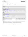
2.7 AT+CFUN
2.7
AT+CFUN Set phone functionality
The AT+CFUN command serves to control the functionality level of the ME. It can be used to reset the ME and
to choose between different modes
.
Syntax
Test Command
AT+CFUN=?
Response(s)
+CFUN: (list of supported <fun>s) , (list of supported <rst>s)
OK
ERROR
+CME ERROR
Read Command
AT+CFUN?
Response(s)
+CFUN: <fun>
OK
ERROR
+CME ERROR
Write Command
AT+CFUN=<fun>[, <rst>]
Response(s)
OK
ERROR
+CME ERROR
Reference(s)
3GPP TS 27.007
PIN
USB0-MDM
USB0-APP
Last
-
+
+
-
Parameter Description
<fun>(num)
0
Minimum functionality. TX and RX RF off. The ME logs off from the network.
The SIM remains accessible for network independent functions.
1(P)
Normal functionality
4
Minimum functionality. TX and RX RF off. The ME logs off from the network.
The SIM remains accessible for network independent functions.
5
Do not use.
6
Do not use.
7
Do not use.
<rst>(num)
Due to the command syntax, you need to enter parameter <fun>, followed by <rst>, where <fun> needs to
be set to 1.
[0]
Do not reset the MT before setting it to <fun> power level.
1
ME resets and restarts. After this, PIN 1 authentication is necessary
(AT+CPIN).
HC15_ATC_V01.001
Confidential / Released
Page 31 of 234
2/16/07
HC15 AT Command Set
s
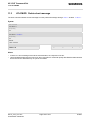
2.8 AT+CMEE
2.8
AT+CMEE Mobile Equipment Error Message Format
AT+CMEE controls the format of the error result codes that indicates errors related to HC15 functionality. Format
can be selected between plain "ERROR" output, error numbers or verbose "+CME ERROR: <err>" and "+CMS
ERROR: <err>" messages.
Possible error result codes are listed in Table 2.1, General "CME ERROR" Codes (GSM 07.07)Table 2.2, GPRS
related "CME ERROR" Codes (GSM 07.07) and Table 2.4, SMS related "CMS ERROR" Codes (GSM 07.05).
Syntax
Test Command
AT+CMEE=?
Response(s)
+CMEE: (list of supported<errMode>s)
OK
Read Command
AT+CMEE?
Response(s)
+CMEE: <errMode>
OK
Exec Command
AT+CMEE
Response(s)
OK
ERROR
+CME ERROR: <err>
Write Command
AT+CMEE=<errMode>
Response(s)
OK
ERROR
+CME ERROR: <err>
Reference(s)
3GPP 27.007
PIN
USB0-MDM
USB0-APP
Last
-
+
+
-
Parameter Description
<errMode>(num)
0(&F)
Disable result code, i.e. only "ERROR" will be displayed.
1
Enable error result code with numeric values.
(P)
2
Enable error result code with verbose (string) values.
Note
•
The exec command performs a write command with factory default parameter setting.
HC15_ATC_V01.001
Confidential / Released
Page 32 of 234
2/16/07
HC15 AT Command Set
s
2.8 AT+CMEE
2.8.1
Table 2.1:
CME/CMS Error Code Overview
General "CME ERROR" Codes (GSM 07.07)
<err> Code
Text (if AT+CMEE=2)
0
phone failure
1
no connection to phone
2
phone-adapter link reserved
3
Operation not allowed
4
Operation not supported
5
PH-SIM PIN required
6
PH-FSIM PIN required
7
PH-FSIM PUK required
10
SIM not inserted
11
SIM PIN required
12
SIM PUK required
13
SIM failure
14
SIM busy
15
SIM wrong
16
Incorrect password
17
SIM PIN2 required
18
SIM PUK2 required
20
Memory full
21
invalid index
22
not found
23
Memory failure
24
text string too long
25
invalid characters in text string
26
dial string too long
27
invalid characters in dial string
30
no network service
31
Network timeout
32
Network not allowed emergency calls only
40
Network personalization PIN required
41
Network personalization PUK required
42
Network subset personalization PIN required
43
Network subset personalization PUK required
44
service provider personalization PIN required
45
service provider personalization PUK required
46
Corporate personalization PIN required
47
Corporate personalization PUK required
100
unknown
HC15_ATC_V01.001
Confidential / Released
Page 33 of 234
2/16/07
HC15 AT Command Set
s
2.8 AT+CMEE
Table 2.2:
GPRS related "CME ERROR" Codes (GSM 07.07)
<err> Code
Text (if AT+CMEE=2)
103
Illegal MS
106
Illegal ME
107
GPRS services not allowed
111
PLMN not allowed
112
Location area not allowed
113
Roaming not allowed in this location area
148
unspecified GPRS error
149
PDP authentication failure
150
invalid mobile class
273
minimum TFT per PDP address error
274
duplicate TFT eval prec index
275
invalid TFT param combination
Table 2.3:
SIEMENS specific "CME ERROR" Codes
<err> Code
Text (if AT+CMEE=2)
257
network rejected supserv request
258
retry operation
259
invalid deflected to number
260
deflected to number
261
unknown subscriber
262
service not available
263
unknown class
264
unknown network message
Table 2.4:
SMS related "CMS ERROR" Codes (GSM 07.05)
<err> Code
Text (if AT+CMEE=2)
0
None
300
ME failure
301
SMS service of ME reserved
302
Operation not allowed
303
Operation not supported
304
Invalid PDU mode parameter
305
Invalid text mode parameter
310
SIM not inserted
311
SIM PIN required
312
PH-SIM PIN required
313
SIM failure
314
SIM busy
315
SIM wrong
316
SIM PUK required
317
SIM PIN2 required
HC15_ATC_V01.001
Confidential / Released
Page 34 of 234
2/16/07
HC15 AT Command Set
s
2.8 AT+CMEE
<err> Code
Text (if AT+CMEE=2)
318
SIM PUK2 required
320
Memory failure
321
Invalid memory index
322
Memory full
330
SMSC address unknown
331
no network service
332
Network timeout
340
NO +CNMA ACK EXPECTED
500
Unknown error
512
User abort
HC15_ATC_V01.001
Confidential / Released
Page 35 of 234
2/16/07
HC15 AT Command Set
s
2.9 AT+CSCS
2.9
AT+CSCS Select TE character set
The AT+CSCS write command informs the TA which character set <chset> is used by the TE. This enables the
TA to convert character strings correctly between TE and ME character sets. See also Section 1.6, Supported
character sets.
Note that when the TA-TE interface is set to 8-bit operation and the used TE alphabet is 7-bit, the highest bit will
be set to zero.
Syntax
Test Command
AT+CSCS=?
Response(s)
+CSCS: (list of supported<chset>s)
OK
Read Command
AT+CSCS?
Response(s)
+CSCS: <chset>
OK
Write Command
AT+CSCS=[<chset>]
Response(s)
OK
Reference(s)
3GPP 27.007
PIN
USB0-MDM
USB0-APP
Last
+
+
+
-
Parameter Description
<chset>(str)
“GSM“
GSM default alphabet (GSM 03.38 subclause 6.2.1);
Note: This setting may cause software flow control problems since the codes
used to stop and resume data flow (XOFF = decimal 19, XON = decimal 17)
are interpreted as normal characters.
“UCS2“
16-bit universal multiple-octet coded character set (ISO/IEC10646 [32]); UCS2
character strings are converted to hexadecimal numbers from 0000 to FFFF;
e.g. "004100620063" equals three 16-bit characters with decimal values 65, 98
and 99.
“IRA“(&F)(P)
International reference alphabet (ITU T T.50)
HC15_ATC_V01.001
Confidential / Released
Page 36 of 234
2/16/07
HC15 AT Command Set
s
2.10 AT+GCAP
2.10
AT+GCAP Request complete TA capabilities list
AT+GCAP returns a list of additional capabilities.
Syntax
Test Command
AT+GCAP=?
Response(s)
OK
Exec Command
AT+GCAP
Response(s)
+GCAP: <name>
OK
Reference(s)
V.250
PIN
USB0-MDM
USB0-APP
Last
+
+
+
-
Parameter Description
<name>(str)
e.g.: +CGSM
Note
•
+CGSM: The response text shows which GSM commands of the ETSI standard are supported.
HC15_ATC_V01.001
Confidential / Released
Page 37 of 234
2/16/07
HC15 AT Command Set
s
2.11 AT^SCFG
2.11
AT^SCFG Extended Configuration Settings
AT^SCFG can be used to query and configure various settings of the HC15.
The AT^SCFG read command returns a list of all supported parameters and their current values.
The AT^SCFG write command queries a configuration parameter (if no value is entered) or sets its value(s).
The following error messages may be returned by the AT^SCFG write commands:
• "+CME ERROR: operation temporary not allowed"
Change of parameter value(s) temporarily not allowed.
• "+CME ERROR: invalid index"
Invalid parameter name or value(s).
• "+CME ERROR: invalid characters in text string"
Character set conversion of parameter value(s) failed.
• "+CME ERROR: memory failure"
Could not allocate necessary memory or storing a parameter failed.
• "+CME ERROR: operation not allowed"
Change of parameter value(s) not allowed
• "+CME ERROR: unknown"
Other error
Syntax
Test Command
AT^SCFG=?
Response(s)
^SCFG: "GPRS/AutoAttach", (list of supported <gaa>s)
^SCFG: "MEShutdown/OnIgnition", (list of supported <msi>s)
^SCFG: "URC/DstIfc", (list of supported <udi>s)
OK
Read Command
AT^SCFG?
Response(s)
^SCFG: "GPRS/AutoAttach", <gaa>
^SCFG: "MEShutdown/OnIgnition", <msi>
^SCFG: "URC/DstIfc", <udi>
OK
Write Command
Automatic GPRS attach
AT^SCFG="GPRS/AutoAttach"[, <gaa>]
Response(s)
^SCFG: "GPRS/AutoAttach", <gaa>
OK
ERROR
+CME ERROR
Write Command
Enable/disable shutdown by ignition line
AT^SCFG="MEShutdown/OnIgnition"[, <msi>]
Response(s)
^SCFG: "MEShutdown/OnIgnition", <msi>
OK
ERROR
+CME ERROR
HC15_ATC_V01.001
Confidential / Released
Page 38 of 234
2/16/07
HC15 AT Command Set
s
2.11 AT^SCFG
Write Command
Configure URC destination interface:
AT^SCFG="URC/DstIfc"[, <udi>]
Response(s)
^SCFG: "URC/DstIfc", <udi>
OK
ERROR
+CME ERROR
PIN
USB0-MDM
USB0-APP
Last
-
+
+
-
Parameter Description
<gaa>(str)
GPRS with AutoAttach
This parameter can be used to control whether the ME will perform a GPRS attach immediately after power-up
and registering to the network or not. If the setting is changed to "enabled" and the ME is not attached yet, it will
not initiate an attach immediately but after the next restart and registration to the network.
Parameter is global for all interfaces, non volatile and will not be reset by AT&F.
“disabled“(D)
GPRS auto attach is disabled
“enabled“
GPRS auto attach is enabled
<msi>(str)
MEShutdown/OnIgnition: Enable/disable shutdown by IGT line
The parameter specifies two different switching modes of the ignition line IGT: The line may either be used only
to switch on the ME, or to switch it on and off.
Parameter <msi> is global for all interfaces, non-volatile and will not be reset by AT&F.
“on“
“off“
Ignition line (IGT) can be used to switch on and off the ME.
(D)
Ignition line (IGT) can be used to switch on the ME.
<udi>(str)
URC destination interface
This parameter can be used to configure the interface which will be used to output URCs. Note that the recommended approach for a typical HC15 application is using the default configuration. If you consider changing the
configuration please carefully read Section 1.4, HC15 AT Command Interpreter and Section 1.8, Unsolicited
Result Code Presentation.
Parameter is global for all interfaces, volatile and will not be reset by AT&F.
If the modem interface is used, then keep in mind, that if the interface is blocked by an active data connection,
then this connection should be periodically suspended to check for pending URCs!
“usb0-mdm“
(P)
“usb0-app“
HC15_ATC_V01.001
Confidential / Released
Use modem interface to output URCs
Use application interface to output URCs
Page 39 of 234
2/16/07
HC15 AT Command Set
s
2.12 AT^SMSO
2.12
AT^SMSO Switch off mobile station
AT^SMSO initiates the power-off procedure.
Syntax
Test Command
AT^SMSO=?
Response(s)
OK
Exec Command
AT^SMSO
Response(s)
OK
ERROR
+CME ERROR
Reference(s)
PIN
USB0-MDM
USB0-APP
Last
SIEMENS
-
+
+
+
Note
•
Do not send any other AT command after AT^SMSO.
HC15_ATC_V01.001
Confidential / Released
Page 40 of 234
2/16/07
HC15 AT Command Set
s
2.13 AT^SUSB
2.13
AT^SUSB USB Configuration
AT^SUSB can be used to query and configure various settings of the USB interface.
In the following the USB composite communication device is referred to as 'modem/net', or short 'MdmNet'.
The AT^SUSB read command returns a list of all supported parameters and their current values.
The AT^SUSB write command queries a configuration parameter (if no value is entered) or sets its value(s).
The command AT^SUSB="MS/Check" returns OK if the USB mass storage is consistent; otherwise it returns with
ERROR/+CME ERROR.
Syntax
Read Command
AT^SUSB?
Response(s)
^SUSB: "Startup", <start>
^SUSB: "MaxPower", <maxpow>
^SUSB: "PowerSource", <powsrc>
^SUSB: "MdmNet/TO", <mnto>
^SUSB: "MS/CRC", <mscrc>
^SUSB: "MS/WProt", <mswprot>
OK
ERROR
+CME ERROR
Write Command
Startup configuration:
AT^SUSB="Startup"[, <start>]
Response(s)
^SUSB: "Startup", <start>
OK
ERROR
+CME ERROR
Write Command
Maximum power:
AT^SUSB="MaxPower"[, <maxpow>]
Response(s)
^SUSB: "MaxPower", <maxpow>
OK
ERROR
+CME ERROR
Write Command
Power source:
AT^SUSB="PowerSource"[, <powsrc>]
Response(s)
^SUSB: "PowerSource", <powsrc>
OK
ERROR
+CME ERROR
HC15_ATC_V01.001
Confidential / Released
Page 41 of 234
2/16/07
HC15 AT Command Set
s
2.13 AT^SUSB
Write Command
Modem Class request timeout period:
AT^SUSB="MdmNet/TO"[, <mnto>]
Response(s)
^SUSB: "MdmNet/TO", <mnto>
OK
ERROR
+CME ERROR
Write Command
Check Mass Storage consistency:
AT^SUSB="MS/Check"
Response(s)
OK
ERROR
+CME ERROR
Write Command
Query Mass Storage CRC:
AT^SUSB="MS/CRC"
Response(s)
^SUSB: "MS/CRC", <mscrc>
OK
ERROR
+CME ERROR
Write Command
Query usable Mass Storage size:
AT^SUSB="MS/FSize"
Response(s)
^SUSB: "MS/FSize", <msfs>
OK
ERROR
+CME ERROR
Write Command
Mass Storage write protection:
AT^SUSB="MS/WProt"[, <mswprot>]
Response(s)
^SUSB: "MS/WProt", <mswprot>
OK
ERROR
+CME ERROR
HC15_ATC_V01.001
Confidential / Released
Page 42 of 234
PIN
USB0-MDM
USB0-APP
Last
-
+
+
-
2/16/07
HC15 AT Command Set
s
2.13 AT^SUSB
Parameter Description
<start>(str)
USB Startup configuration
This parameter can be used to control the USB Startup configuration. Any change of this parameter becomes
active with the next restart.
Parameter is global for all interfaces, non volatile and will not be reset by AT&F.
“MS“
Startup as USB mass storage device
(D)
“MdmNet“
Startup as USB composite communication device (modem)
<maxpow>(str)
Maximum power
Maximum power consumption of the USB device from the USB bus. This parameter is reported to an USB host
as part of the USB enumeration.
Only even values are supported. Odd values are truncated.
Any change of this parameter becomes active with the next device enumeration.
Parameter is global for all interfaces, non volatile and will not be reset by AT&F.
0...10(D)...500
Device maximum power consumption in mA
<powsrc>(str)
Power source
This parameter can be used to specify the power source. Any change of this parameter becomes active with the
next device enumeration.
Parameter is global for all interfaces, non volatile and will not be reset by AT&F.
“BUS“
Device enumerates as bus powered device
(D)
“SELF“
Device enumerates as self powered device
<mnto>(str)
Mode/Net Class Request timeout
This parameter can be used to specify the timeout for the Modem/Net Comunication Device Class Request. Any
change of this parameter becomes active with the next restart.
Parameter is global for all interfaces, non volatile and will not be reset by AT&F.
“0“
no timeout supervision
(D)
100...10000 ...65535
Timeout in ms
<msfs>(str)
Mass storage size
This parameter specifies the usable USB mass storage size.
0...2147483647
Usable mass storage size in bytes.
<mscrc>(str)
Mass storage CRC value
This parameter specifies the USB mass storage CRC value.
00000000...FFFFFFFF
HC15_ATC_V01.001
Confidential / Released
8 digit ASCII hex CRC value; if CRC recalculation is not finished yet, then a
ASCII question mark is appended
Page 43 of 234
2/16/07
HC15 AT Command Set
s
2.13 AT^SUSB
<mswprot>(str)
Mass storage write protection
This parameter can be used to enable or disable the USB mass storage write protection. communication device
(modem). Any change of this parameter becomes active immediately.
Parameter is global for all interfaces, non volatile and will not be reset by AT&F.
“Enabled“
“Disabled“
Mass storage is write protected
(D)
HC15_ATC_V01.001
Confidential / Released
Mass storage is not write protected
Page 44 of 234
2/16/07
HC15 AT Command Set
s
3. Status Control Commands
3.
Status Control Commands
The AT Commands described in this chapter allow the external application to obtain various status information
from the HC15.
3.1
AT+CEER Extended Error Report
AT+CEER returns an extended error report regarding the reason of the last
• call release
• failure to set up a call (both mobile originated or terminated)
• failure to modify a call by using Supplementary Services
• failed attempt to activate, register, query, deactivate or deregister a Supplementary Service
• unsuccessful GPRS attach or unsuccessful PDP context activation
• GPRS detach or PDP context deactivation
≠≠The release cause report <report> is a single line containing the cause information given by GSM network
in textual format.
Syntax
Test Command
AT+CEER=?
Response(s)
OK
ERROR
+CME ERROR
Exec Command
AT+CEER
Response(s)
+CEER: <report>
OK
ERROR
+CME ERROR
Reference(s)
PIN
USB0-MDM
USB0-APP
Last
GSM 07.07
+
+
+
-
Parameter Description
<report>(str)
release cause report
Reason for the last call failure to setup or release (listed in Section 3.1.1, List of status codes for the extended
error report).
Both CS and PS domain call types are reported. Cause data is captured from Call Manager events and cached
locally to later use by this command.
HC15_ATC_V01.001
Confidential / Released
Page 45 of 234
2/16/07
HC15 AT Command Set
s
3.1 AT+CEER
3.1.1
List of status codes for the extended error report
CS internal cause lookup
No cause information available (default)
Phone is offline
No service available
Network release, no reason given
Received incoming call
Client ended call
UIM not present
Access attempt already in progress
Access failure, unknown source
Concur service not supported by network
No response received from network
GPS call ended for user call
SMS call ended for user call
Data call ended for emergency call
Rejected during redirect or handoff
Lower-layer ended call
Call origination request failed
Client rejected incoming call
Client rejected setup indication
Network ended call
No funds available
No service available
Full service not available
Maximum packet calls exceeded
Video connection lost
Video protocol closed after setup
Video protocol setup failure
Internal error
CS network cause lookup
Unassigned/unalloacted number
No route to destination
Channel unacceptable
Operator determined barring
Normal call clearing
User busy
No user responding
User alerting, no answer
HC15_ATC_V01.001
Confidential / Released
Page 46 of 234
2/16/07
HC15 AT Command Set
s
3.1 AT+CEER
CS network cause lookup
Call rejected
Number changed
Non selected user clearing
Destination out of order
Invalid/incomplete number
Facility rejected
Response to Status Enquiry
Normal, unspecified
No circuit/channel available
Network out of order
Temporary failure
Switching equipment congestion
Access information discarded
Requested circuit/channel not available
Resources unavailable, unspecified
Quality of service unavailable
Requested facility not subscribed
Incoming calls barred within the CUG
Bearer capability not authorized
Bearer capability not available
Service/option not available
Bearer service not implemented
ACM >= ACMmax
Requested facility not implemented
Only RDI bearer is available
Service/option not implemented
Invalid transaction identifier value
User not member of CUG
Incompatible destination
Invalid transit network selection
Semantically incorrect message
Invalid mandatory information
Message non-existent/not implemented
Message type not compatible with state
IE non-existent/not implemented
Conditional IE error
Message not compatible with state
Recovery on timer expiry
Protocol error, unspecified
Interworking, unspecified
HC15_ATC_V01.001
Confidential / Released
Page 47 of 234
2/16/07
HC15 AT Command Set
s
3.1 AT+CEER
CS network reject lookup
IMSI unknown in HLR
Illegal MS
IMSI unknown in VLR
IMEI not accepted
Illegal ME
GPRS services not allowed
GPRS and non GPRS services not allowed
MS identity cannot be derived
Implicitly detached
PLMN not allowed
Location Area not allowed
Roaming not allowed
GPRS services not allowed in PLMN
No Suitable Cells In Location Area
MSC temporarily not reachable
Network failure
MAC failure
Synch failure
Congestion
GSM authentication unacceptable
Service option not supported
Requested service option not subscribed
Service option temporarily out of order
Call cannot be identified
No PDP context activated
Semantically incorrect message
Invalid mandatory information
Message type non-existent
Message type not compatible with state
Information element non-existent
Message not compatible with state
RR release indication
RR random access failure
RRC release indication
RRC close session indication
RRC open session failure
Low level failure
Low level failure no redial allowed
Invalid SIM
No service
Timer T3230 expired
HC15_ATC_V01.001
Confidential / Released
Page 48 of 234
2/16/07
HC15 AT Command Set
s
3.1 AT+CEER
CS network reject lookup
No cell available
Wrong state
Access class blocked
Abort message received
Other cause
Timer T303 expired
No resources
Release pending
Invalid user data
PS internal cause lookup
Invalid connection identifier
Invalid NSAPI
Invalid Primary NSAPI
PDP establish timeout
Invalid field
SNDCP failure
RAB setup failure
No GPRS context
PDP activate timeout
PDP modify timeout
PDP inactive max timeout
PDP lowerlayer error
PDP duplicate
Access technology change
PDP unknown reason
CS PS network cause lookup
LLC or SNDCP failure
Insufficient resources
Missing or unknown APN
Unknown PDP address or PDP type
User Aauthentication failed
Activation rejected by GGSN
Activation rejected, unspecified
Service option not supported
Requested service option not subscribed
Service option temporarily out of order
NSAPI already used (not sent)
Regular deactivation
QoS not accepted
Network failure
HC15_ATC_V01.001
Confidential / Released
Page 49 of 234
2/16/07
HC15 AT Command Set
s
3.1 AT+CEER
CS PS network cause lookup
Reactivation required
Feature not supported
Semantic error in the TFT operation
Syntactical error in the TFT operation
Unknown PDP context
PDP context without TFT already activated
Semantic errors in packet filter
Syntactical errors in packet filter
Invalid transaction identifier
Semantically incorrect message
Invalid mandatory information
Message non-existent/not implemented
Message type not compatible with state
IE non-existent/not implemented
Conditional IE error
Message not compatible with state
Protocol error, unspecified
HC15_ATC_V01.001
Confidential / Released
Page 50 of 234
2/16/07
HC15 AT Command Set
s
3.2 AT+CPAS
3.2
AT+CPAS Mobile equipment activity status
The AT+CPAS execute command indicates the activity status of the ME.
Syntax
Test Command
AT+CPAS=?
Response(s)
+CPAS: (list of supported<pas>s)
OK
Exec Command
AT+CPAS
Response(s)
+CPAS: <pas>
OK
Reference(s)
PIN
USB0-MDM
USB0-APP
Last
GSM 07.07
-
+
+
-
Parameter Description
<pas>(num)
0
Ready
3
Incoming call (ringing)
4
Call in progress
HC15_ATC_V01.001
Confidential / Released
Page 51 of 234
2/16/07
HC15 AT Command Set
s
3.3 AT+WS46
3.3
AT+WS46 Select wireless network
The AT+WS46 command is intended for reading the current status of the network selection. The write command
has no effect. To select the network please use the AT+COPS command.
Syntax
Test Command
AT+WS46=?
Response(s)
+WS46: (list of supported<n>s)
OK
Read Command
AT+WS46?
Response(s)
<n>
OK
Write Command
AT+WS46=[<n>]
Response(s)
OK
ERROR
+CME ERROR
Reference(s)
PIN
USB0-MDM
USB0-APP
Last
GSM 07.07
-
+
+
-
Parameter Description
<n>(num)
12
GSM Digital Cellular Systems (GERAN only)
22
UTRAN only
25
3GPP Systems (both GERAN and UTRAN)
HC15_ATC_V01.001
Confidential / Released
Page 52 of 234
2/16/07
HC15 AT Command Set
s
4. Serial Interface Control Commands
4.
Serial Interface Control Commands
The AT Commands described in this chapter allow the external application to determine various settings related
to the HC15's serial interface.
4.1
AT^SQPORT Query Port Type
AT^SQPORT enables the host application to query the type of virtual COM port it is connected to. Further details
on the different types of virtual HC15 interfaces can be found in Section 1.4, HC15 AT Command Interpreter.
Syntax
Test Command
AT^SQPORT=?
Response(s)
OK
Read Command
AT^SQPORT?
Response(s)
<type>
OK
Exec Command
AT^SQPORT
Response(s)
<type>
OK
Reference(s)
Siemens
PIN
USB0-MDM
USB0-APP
Last
-
+
+
-
Parameter Description
<type>(str)
“Modem“
The virtual COM port is defined for use as a modem, mainly intended for dialup connections. Using AT commands is not recommended except for the dialing command ATD.
“Application“
The virtual COM port is defined as application interface. It is recommended that
this interface be used for controlling the HC15, e.g. for entering AT commands,
receiving URCs, or sending and receiving short messages. URCs are indicated
only on this interface, no matter which of the two interfaces was used to send
the AT commands for activating their presentation. For further detail on URCs
please refer to Section 1.8, Unsolicited Result Code Presentation.
HC15_ATC_V01.001
Confidential / Released
Page 53 of 234
2/16/07
HC15 AT Command Set
s
4.2 AT&C
4.2
AT&C Set Data Carrier Detect (DCD) Line mode
The AT&C command determines how the state of the DCD line (circuit 109) of the virtual modem COM port
reflects the HC15's internal activity.
Syntax
Exec Command
AT&C[<value>]
Response(s)
OK
Reference(s)
V.250
PIN
USB0-MDM
USB0-APP
Last
+
+
+
-
Parameter Description
<value>(num)
[0]
DCD line shall always be on.
1
DCD line shall be on only when data carrier signal is present.
(&F)
2
HC15_ATC_V01.001
Confidential / Released
Setting winks (briefly transitions off, then back on) the DCD line when data calls
end.
Page 54 of 234
2/16/07
HC15 AT Command Set
s
4.3 AT&D
4.3
AT&D Set circuit Data Terminal Ready (DTR) function mode
The AT&D determines how the TA responds when circuit 108/2 (DTR) is changed from ON to OFF during data
mode.
Syntax
Exec Command
AT&D[<value>]
Response(s)
OK
Reference(s)
V.250
PIN
USB0-MDM
USB0-APP
Last
+
+
+
-
Parameter Description
<value>(num)
[0]
TA ignores status of DTR.
1
ON->OFF on DTR: Change to command mode while retaining the connected
call.
2(&F)
ON->OFF on DTR: Disconnect data call, change to command mode. During
state DTR = OFF auto-answer is off.
HC15_ATC_V01.001
Confidential / Released
Page 55 of 234
2/16/07
HC15 AT Command Set
s
4.4 ATE
4.4
ATE Enable command echo
The ATE command determines whether or not the TA echoes characters received from TE during command
state.
Syntax
Exec Command
ATE[<value>]
Response(s)
OK
Reference(s)
V.250
PIN
USB0-MDM
USB0-APP
Last
-
+
+
-
Parameter Description
<value>(num)
[0]
(&F)
1
HC15_ATC_V01.001
Confidential / Released
Echo mode off
Echo mode on
Page 56 of 234
2/16/07
HC15 AT Command Set
s
5. Security Commands
5.
Security Commands
The AT Commands described in this chapter allow the external application to determine various security related
settings.
5.1
AT+CLCK Facility lock
AT+CLCK can be used to lock, unlock or interrogate a network or ME <facility>. The command can be
aborted when network facilities are being set or interrogated.
Syntax
Test Command
AT+CLCK=?
Response(s)
+CLCK:list of supported <facility>s
OK
Write Command
AT+CLCK=<facility>, <mode>[, <password>][, <class>]
Response(s)
if <mode> is not equal 2 and command successful:
OK
if <mode>= 2 and command successful:
+CLCK: <status>[, <class>]
[+CLCK: <status>[, <class>]]
[+CLCK: ...]
OK
If error is related to ME functionality
+CME ERROR
Reference(s)
GSM 07.07, GSM 02.04, GSM 02.88,
GSM 03.88, GSM 04.88
PIN
USB0-MDM
USB0-APP
Last
+
+
+
-
Parameter Description
<facility>(str)
Phone security locks set by client or factory
Primarily intended for the client to take safety precautions, "SC"can be configured individually.
Parameter <class> is not applicable to security locks.
See examples below for further details.
“SC“
SIM (lock SIM cards). SIM requests password upon ME power-up and when
this lock command is issued.
<password>: SIM PIN1.
“FD“
SIM fixed dialling memory: If the mobile is locked to "FD", only the phone numbers stored to the "FD" memory can be dialled. (Capacity of FD phonebook
depending on the SIM card).
<password>: SIM PIN 2.
If a lock on the SIM fixed dialing memory is active, the following applies:
HC15_ATC_V01.001
Confidential / Released
Page 57 of 234
2/16/07
HC15 AT Command Set
s
5.1 AT+CLCK
•
Outgoing voice, data or fax calls can be made only to numbers stored in
''FD'' phonebook.
Result code depends on the type of the call:
for voice calls, indication is ''+CME Error 257: Call barred''.
for data and fax calls, indication is ''NO CARRIER''.
•
Access to defined Supplementary Services such as Call barring, Call waiting, Call forwarding, Call hold and Multiparty is possible only if the exact corresponding public MMI *# code for the desired service is stored in the fixed
dialing number phone book, and used with ATD.
AT commands for supplementary service control are barred while "FD" lock
is active.
Indication is ''+CME Error 257: Call barred''.
•
Access to Unstructured Supplementary Services (''USSD'') is possible only
if the exact desired USSD string is stored in the fixed dialling number phone
book, and used with ATD.
AT commands for USSD are barred while "FD" lock is active.
Indication is ''+CME Error 257: Call barred''.
•
SMS can be sent only to phone numbers which are stored in the ''fixed dialling numbers'' phonebook ''FD''.
Indication is ''+CMS Error 302: operation not allowed''.
•
GPRS commands can be used only if the ''fixed dialling numbers'' phonebook ''FD'' contains an entry with phone number ''*99#''. This single entry
enables all GPRS commands, including AT commands and modem compatibility commands like ''ATD*99***1#'' or ''ATD*98***1#''.
Indication is ''+CME Error 257: Call barred''.
Supplementary Service Call Barring:
Supplementary Service "Call Barring" allows to specify conditions under which calls will be disallowed by the
network.
The availability of the Supplementary Services varies with the network. To benefit from call barring the client will
need to subscribe them, though a limited number of call barring types may be included in the basic tariff package.
When you attempt to set a <facility> or <class> which is not provisioned, not yet subscribed to, or not supported by the module, the setting will not take effect regardless of the response returned. The responses in these
cases vary with the network (for example "OK", "+CME ERROR: Operation not allowed", "+CME ERROR: Operation not supported" etc.). To make sure check the extended error response with AT+CEER and the lock status
with <mode>=2.
<password>: Network password supplied from the provider or operator. Usually there is one password which
applies to all call barring options. For details contact your provider.
“AO“
BAOC (Bar All Outgoing Calls)
“OI“
BOIC (Bar Outgoing International Calls)
“OX“
BOIC-exHC (Bar Outgoing International Calls except to Home Country)
“AI“
BAIC (Bar All Incoming Calls)
“IR“
BIC-Roam (Bar Incoming Calls when Roaming outside the home country)
“AB“
All Barring services (applicable only for <mode>=0)
“AG“
All outGoing barring services (applicable only for <mode>=0)
“AC“
All inComing barring services (applicable only for <mode>=0)
<mode>(num)
0
unlock
1
lock
2
query status
HC15_ATC_V01.001
Confidential / Released
Page 58 of 234
2/16/07
HC15 AT Command Set
s
5.1 AT+CLCK
<status>(num)
0
lock is inactive
1
lock is active
<password>(str)
Password string used to lock and to unlock a <facility>. Length and authority for passwords depend on the
<facility> in question and are therefore listed in the section on parameter <facility>. Passwords can be
modified with AT+CPWD.
<class>(num)
Integer or sum of integers each representing a class of information, i.e. a bearer service, telecommunication service or bearer service group as defined in "GSM 02.04".
1
voice
2
class 2 ("data") comprises all those individual data classes between 16 and
128, that are supported both by the network and the MS. This means, a setting
made for class 2 applies to all individual data classes (if supported). In addition,
you can assign a different setting to a specific class. For example, you can activate Call Forwarding for all data classes, but deactivate it for data class 64,
"dedicated packet access".
4
fax
8
SMS
16
data circuit sync
32
data circuit async
64
dedicated packet access
128
dedicated PAD access
1...[7]...255
combination of some of the above classes.
For example, the default setting 7 represents the sum of the integers 1, 2 and
4 (voice, data and fax).
The value 255 covers all classes.
If parameter "class" is omitted, the default value 7 is used.
Notes
•
The AT+CLCK command offers the full range of <class> parameters according to the GSM specifications.
However, when you attempt to use a service option which is not provisioned or not yet subscribed to, the setting will not take effect regardless of the response returned.
The responses in these cases vary with the network (for example "OK", "Operation not allowed", "Operation
not supported" etc.). To make sure check the extended error response with AT+CEER and the lock status with
<mode>=2.
•
The command has been implemented with the full set of <class> parameters according to GSM 07.07. For
actual applicability of a desired Call barring service to a specific service or service group (a specific <class>
value) please consult table A.1 of GSM 02.04.
•
If an outgoing Fax or Data Call is rejected due to an active ''call barring'' supplementary service, the call will
be terminated with result code NO CARRIER.
Under the same conditions, an outgoing Voice call will be terminated with result code NO DIALTONE.
•
If an invalid <password> is entered several times in succession, a delay incremented after each failed
attempt will increase the time to wait before the input of the <password> is accepted. To avoid blocking the
serial interface the running AT+CLCK command is aborted after a short timeout and returns CME ERROR 100
("unknown"). If then the AT+CLCK command is issued once again execution is denied with CME ERROR 256
("Operation temporary not allowed"). For details regarding the delay see Section 5.2.1, What to do if PIN or
password authentication fails?.
HC15_ATC_V01.001
Confidential / Released
Page 59 of 234
2/16/07
HC15 AT Command Set
s
5.1 AT+CLCK
•
If the user tries to set a lock although it is already active or, the other way round, tries to unlock an inactive
lock, the response will be OK, but the <password> will not be checked or verified.
•
As stated above <class> 2 is intended only to send the data classes 16/32/64/128 to the network. However,
the responses returned when the subscriber sets or queries the lock refer only to the status of the data classes
received from the network. This means that the responses will display only those data classes between 16
and 128 which are supported by the network and currently activated. There will be no output for class 2, nor
for classes which are not supported or not set.
•
The parameter <class> will not be sent to the network if <mode>=2. Therefore it may happen that the
response of the query command contains information about classes which were not requested, or it shows
only the inactive status of the class 1 or 255. This means that the status is valid for all classes.
Example
Lock SIM card (<facility>= "SC")
AT+CLCK="SC",1,"9999"
OK
AT+CLCK="SC",0,"9999"
OK
The "SC" parameter enables or disables the SIM PIN authentication
(PIN 1) when you power up the GSM engine
SIM card locked. As a result, SIM PIN 1 must be entered to enable ME
to register to the GSM network.
Unlocks SIM card.
When powered up, ME registers to the GSM network without requesting
SIM PIN1.
Note: Depending on the services offered by the provider, this feature is
not supported by all SIM card types. If so, the command returns ERROR
when you attempt to unlock the card.
To query the status of the SIM card lock:
AT+CLCK="SC",2
+CLCK: 1
Query the status of SIM card lock.
SIM card is locked. SIM PIN1 must be entered to enable ME to register
to the GSM network.
OK
HC15_ATC_V01.001
Confidential / Released
Page 60 of 234
2/16/07
HC15 AT Command Set
s
5.2 AT+CPIN
5.2
AT+CPIN PIN Authentication
AT+CPIN controls network authentication of the HC15.
The read command returns an alphanumeric string indicating whether or not network authentication is required.
The write command allows the HC15 to store the entered password. This may be for example the SIM PIN1 to
register to the GSM network, or the SIM PUK1 to replace a disabled SIM PIN1 with a new one, or the PH-SIM
PIN if the client has taken precautions for preventing damage in the event of loss or theft etc.
If no PIN1 request is pending (for example if PIN1 authentication has been done and the same PIN1 is entered
again) HC15 responds "+CME ERROR: operation not allowed"; no further action is required.
Each time a password is entered with AT+CPIN the module starts reading data from the SIM. The duration of
reading varies with the SIM card. This may cause a delay of several seconds before all commands which need
access to SIM data are effective. See Section 17.1, Restricted access to SIM data after SIM PIN authentication
for further detail.
Syntax
Test Command
AT+CPIN=?
Response(s)
OK
Read Command
AT+CPIN?
Response(s)
+CPIN: <code>
OK
ERROR
+CME ERROR: <err>
Write Command
AT+CPIN=<pin>[, <new pin>]
Response(s)
OK
ERROR
+CME ERROR: <err>
Reference(s)
PIN
USB0-MDM
USB0-APP
Last
GSM 07.07
-
+
+
-
Parameter Description
<pin>(str)
Password (string type), usually SIM PIN1.
If the requested password was a PUK, such as SIM PUK1 or PH-FSIM PUK or another password, then <pin>
must be followed by <new pin>.
<new pin>(text)
If the requested code was a PUK: specify a new password or restore the former disabled password. See Section
5.2.1, What to do if PIN or password authentication fails? for more information about when you may need to
enter the PUK.
HC15_ATC_V01.001
Confidential / Released
Page 61 of 234
2/16/07
HC15 AT Command Set
s
5.2 AT+CPIN
<code>(text)
SIM PIN authentication
READY
PIN has already been entered. No further entry needed.
SIM PIN
ME is waiting for SIM PIN1.
SIM PUK
ME is waiting for SIM PUK1 if PIN1 was disabled after three failed attempts to
enter PIN1.
SIM PIN2
ME is waiting for PIN2.
SIM PUK2
ME is waiting for PUK2 to unblock a disabled PIN2.
Phone security locks set by client or factory
PH-SIM PIN
ME is waiting for phone-to-SIM card password if "PS" lock is active and the client inserts other SIM card than the one used for the lock. ("PS" lock is also
referred to as phone or antitheft lock).
PH-FSIM PIN
ME is waiting for phone-to-very-first-SIM card. Necessary when "PF" lock was
set. When powered up the first time, ME locks itself to the first SIM card put into
the card holder. As a result, operation of the mobile is restricted to this one SIM
card (unless the PH-FSIM PUK is used as described below).
PH-FSIM PUK
ME is waiting for phone-to-very-first-SIM card unblocking password to be
given. Necessary when "PF" lock is active and other than first SIM card is
inserted.
PH-NET PIN
ME is waiting for network personalisation password
PH-NET PUK
ME is waiting for network personalisation unblocking password
PH-NETSUB PIN
ME is waiting for network subset personalisation password
PH-NETSUB PUK
ME is waiting for network subset unblocking password
PH-SP PIN
ME is waiting for service provider personalisation password
PH-SP PUK
ME is waiting for service provider personalisation unblocking password
PH-CORP PIN
ME is waiting for corporate personalisation password
PH-CORP PUK
ME is waiting for corprorate personalisation un-blocking password
Notes
•
Successful PIN authentication only confirms that the entered PIN was recognized and correct. The output of
the result code OK does not necessarily imply that the mobile is registered to the desired network.
Typical example: PIN was entered and accepted with OK, but the ME fails to register to the network. This may
be due to missing network coverage, denied network access with currently used SIM card, no valid roaming
agreement between home network and currently available operators etc.
HC15 offers various options to verify the present status of network registration: For example, the AT+COPS
command indicates the currently used network. With AT+CREG you can also check the current status and activate an unsolicited result code which appears whenever the status of the network registration changes (e.g.
when the ME is powered up, or when the network cell changes).
•
<pin> and <new pin> can also be entered in quotation marks (e.g. "1234").
•
See AT+CPWD for information on passwords.
•
See AT+CLCK for information on lock types.
•
See AT+CPBS for information on write access to the FD phonebook with PIN2
HC15_ATC_V01.001
Confidential / Released
Page 62 of 234
2/16/07
HC15 AT Command Set
s
5.2 AT+CPIN
5.2.1
What to do if PIN or password authentication fails?
PIN1 / PUK1:
After three failures to enter PIN 1, the SIM card is blocked (except for emergency calls). +CME ERROR: 12 will
prompt the client to unblock the SIM card by entering the associated PUK (= PIN Unblocking Key / Personal
Unblocking Key). After ten failed attempts to enter the PUK, the SIM card will be invalidated and no longer operable In such a case, the card needs to be replaced. PIN1 consists of 4 to 8 digits, PUK1 is an 8-digit code only.
To unblock a disabled PIN1 you have two options:
•
•
You can enter AT+CPIN=PUK1,new PIN1.
You can use the ATD command followed by the GSM code **05*PUK*newPIN*newPIN#;.
PIN2 / PUK2:
PIN2 prevents unauthorized access to the features listed in AT+CPIN. The handling of PIN2 varies with the provider. PIN2 may either be a specific code supplied along with an associated PUK2, or a default code such as
0000. In either case, the client is advised to replace it with an individual code. Incorrect input of PUK2 will permanently block the additional features subject to PIN2 authentification, but usually has no effect on PIN1. PIN2
consists of 4 digits, PUK2 is an 8-digit code only.
To unblock a disabled PIN2 you have two options:
•
•
You can enter AT+CPIN=PUK2,new PIN2.
You can use the ATD command followed by the GSM code **052*PUK2*newPIN2*newPIN2#;.
SIM locks:
These are factory set locks, such as "PF", "PN", "PU", "PP", "PC". An 8-digit unlocking code is required to operate
the mobile with a different SIM card, or to lift the lock. The code can only be obtained from the provider.
If incorrectly input, the password is governed by a specific timing algorithm: (n-1)*256 seconds (see table below).
Number of failed attempts
Time to wait before next input is allowed
1st failed attempt
No time to wait
2nd failed attempt
4 seconds
3rd failed attempt
3 * 256 seconds
4th failed attempt
4 * 256 seconds
5th failed attempt
5 * 256 seconds
6th failed attempt and so forth
6 * 256 seconds and so forth
Call barring:
Supported modes are "AO", "OI", "OX", "AI", "IR", "AB", "AG", "AC". If the call barring password is entered incorrectly three times, the client will need to contact the service provider to obtain a new one.
Related sections:
"+CME ERROR: <err>" values are specified at Section 2.8.1, CME/CMS Error Code Overview. For further
instructions and examples see AT+CLCK and AT+CPWD.
For a complete list of Star-Hash codes please refer Section 17.2, Star-Hash (*#) Network Commands.
HC15_ATC_V01.001
Confidential / Released
Page 63 of 234
2/16/07
HC15 AT Command Set
s
5.3 AT+CPWD
5.3
AT+CPWD Change Password
AT+CPWD allows to define a new password for a password protected <facility> lock function. Each password
is a string of digits, the length of which varies with the associated <facility>. The test command returns a list
of pairs which represent the available facilities and the maximum length of the associated password. See AT
commands AT+CLCK for more information on the various lock features.
To delete a password use the following syntax: at+cpwd=<facility>,<old password>
Syntax
Test Command
AT+CPWD=?
Response(s)
+CPWD:list of supported (<facility>, <password length>)
OK
Write Command
AT+CPWD=<facility>, <old password>[, <new password>]
Response(s)
New password has been registered for the facility lock function.
OK
If parameter <old password> was not correct:
+CME ERROR 16 (+CME ERROR: incorrect password)
If the password for the selected <facility> has been invalidated due to too many failed attempts:
+CME ERROR ...
If the network provider or network operator doesn't supply the Network Password:
+CME ERROR: 258 (+CME ERROR: retry operation)
If error is related to ME functionality:
+CME ERROR
Reference(s)
PIN
USB0-MDM
USB0-APP
Last
GSM 07.07
+
+
+
-
Parameter Description
<facility>(str)
Phone security locks set by client or factory:
Primarily intended for the client to take safety precautions, passwords "SC" (SIM PIN) and "P2" (SIM PIN2) are
usually predefined, but can be configured individually.
“SC“
SIM PIN. SIM requests password upon ME power-up and when this lock command is issued.
If incorrectly entered three times, the SIM PUK is required to perform authentication. Input of the SIM PUK password is possible only with AT command
AT+CPIN or ATD. For further details please refer to Section 5.2.1, What to do
if PIN or password authentication fails?.
<password length>: 4 to 8 digits.
“P2“
SIM PIN 2, e.g. required for authentication with facility lock "FD" (cf. AT+CLCK).
If incorrectly entered three times, the SIM PUK 2 is required to perform authentication. Input of the SIM PUK 2 password is possible only with AT command
AT+CPIN or ATD. For further detail please refer to Section 5.2.1, What to do if
PIN or password authentication fails?.
<password length>: 4 to 8 digits.
HC15_ATC_V01.001
Confidential / Released
Page 64 of 234
2/16/07
HC15 AT Command Set
s
5.3 AT+CPWD
Supplementary Service Call Barring:
The call barring supplementary service allows to specify conditions under which calls will be disallowed by the
network.
The availability of the supplementary services varies with the network. To benefit from call barring the client will
need to subscribe them, though a limited number of call barring types may be included in the basic tariff package.
<password length>: ThenNetwork password needs to be supplied from the network provider or network
operator. Usually there is one 4 digit password which applies to all call barring options. For details contact your
provider.
“AO“
BAOC (Bar All Outgoing Calls)
“OI“
BOIC (Bar Outgoing International Calls)
“OX“
BOIC-exHC (Bar Outgoing International Calls except to Home Country)
“AI“
BAIC (Bar All Incoming Calls)
“IR“
BIC-Roam (Bar Incoming Calls when Roaming outside the home country)
“AB“
All Barring services
“AG“
All outGoing barring services
“AC“
All inComing barring services
<password length>(num)
4...8
Length of password. The range of permitted length for a password depends on
the associated <facility>. It is available from the test command response,
or in the description of parameter <facility>. If the entered password is
longer then the maximum password length it will be stripped to the maximum
length and the remaining digits will be ignored.
<old password>(str)
Password specified for the facility.
Parameter <old password> can be ignored if no old password was allocated to the facility.
Take into account that a password may have already been set by factory, or that the service is subject to a password issued by the provider. See notes above or contact provider.
<new password>(str)
New password. Mandatory, if <old password> was an unblocking key (PUK).
Note
•
As stated above there is usually a one 4-digit password for all call barring facilities. To change the password
please use only the "AB" <facility> (All Barring services).
Examples
EXAMPLE 1
To change PIN2
AT+CPWD="P2","0000","8888"
OK
(where "0000" = old PIN2 and "8888" = new PIN2)
PIN2 password has been changed to "8888"
EXAMPLE 2
To set the password used to enable or disable Call Barring:
AT+CPWD="AB","0000","3333"
OK
HC15_ATC_V01.001
Confidential / Released
Requests the network to change the password for
the call barring supplementary service.
Even though issued for "AB" only the request applies
to all other call barring services, too.
Page 65 of 234
2/16/07
HC15 AT Command Set
s
5.4 AT^SCSL
5.4
AT^SCSL Customer SIM Lock
AT^SCSL is a Siemens defined command especially designed to manage the Customer SIM Lock feature. This
feature allows application manufacturers to lock a mobile to specific operators by activating a Network Personalization ("PN"). If the lock is enabled the mobile will accept only SIM cards from the given operators.
The lock is activated by specifying the mobile country codes and mobile networks codes on command line.
The Customer SIM Lock feature is protected by depersonalization key.
Syntax
Test Command
AT^SCSL=?
Response(s)
OK
Write Command
AT^SCSL=<facility>, <action>[, <password>, <data>]
Response(s)
OK
ERROR
CME ERROR
Reference(s)
Siemens
PIN
USB0-MDM
USB0-APP
Last
-
+
+
-
Parameter Description
<facility>(str)
“PN“
Network Personalisation (= Customer SIM Lock)
<action>(num)
0
Delete programmed SIM lock data and disable the personalization.
Required parameters: <facility>="PN", <action>=0, <password>.
Removing the Customer SIM Lock deletes all <data>, i.e. the entire list of
operators .
1
Program given SIM lock data and activate SIM lock.
Required parameters: <facility>="PN", <action>=1, <password>,
<data>.
2
Request Customer SIM Lock status.
Required parameters: <facility>="PN", <action>=2.
4
Request the depersonalization key, allowed if Customer SIM Lock has not
already been programmed. Otherwise returns error.
Required parameters: <facility>="PN", <action>=4.
<password>(str)
Depersonalization key associated with the device. The password is not needed for <action>=2 and
<action>=4.
<data>(str)
Data of the allowed network operators.
Each operator code consists of the "Mobile Country Code" MCC and the "Mobile Network Code" MNC, both separated by a dot, e.g. MCC1.MNC1. If more than one operator is entered on the same line, then a colon must be
set between each operator code, e.g. MCC1.MNC1:MCC2.MNC2:MCC3.MNC3. For example, for the three
HC15_ATC_V01.001
Confidential / Released
Page 66 of 234
2/16/07
HC15 AT Command Set
s
5.4 AT^SCSL
operators T-Mobile D, Vodafone D2 and E-Plus you would enter the following data: 262.01:262.02:262.03
Note that each time the AT^SCSL write command is executed using the parameter <action>=1 the existing
operator codes will not be overwritten, but all new data will be added to the list. This applies no matter whether
the same operator code is already listed, i.e. entering the same operator again causes double entries.
Notes
•
Usage of the Customer SIM lock features may be restricted by existing facility locks.
•
Reprogramming active SIM lock is possible, but overwrites previous settings.
•
The Customer SIM Lock takes effect after executing the AT^SCSL write command with <action>=1 and
rebooting the ME. Then, after the reboot, the ME will accept only SIM cards from the supported operators.
Example
To check <password>, configure and remove the Customer SIM Lock:
Check the <password> - possible if Customer SIM
Lock not programmed yet.
AT^SCSL="PN",4
^SCSL: 12345678
OK
AT^SCSL="PN",2
^SCSL: 0
OK
AT^SCSL="PN",1,"12345678","MCC1.MNC1:MCC2.M
NC2"
OK
AT^SCSL="PN",2
^SCSL: 1
OK
AT^SCSL="PN",0,"12345678"
OK
HC15_ATC_V01.001
Confidential / Released
Request status
SIM Lock disabled
Program Customer SIM Lock
Request status
SIM Lock enabled
Remove Customer SIM Lock
Page 67 of 234
2/16/07
HC15 AT Command Set
s
6. Identification Commands
6.
Identification Commands
The AT Commands described in this chapter allow the external application to obtain various identification information related to the HC15 and linked entities.
6.1
ATI Display product identification information
The ATI execute command delivers a product information text.
The 'Revision' information consists of the following parts: Version xx and variant yy of software release.
Syntax
Exec Command
ATI
Response(s)
SIEMENS
HC15
REVISION xx.yy
OK
Exec Command
ATI
Response(s)
OK
Reference(s)
V.250
HC15_ATC_V01.001
Confidential / Released
Page 68 of 234
PIN
USB0-MDM
USB0-APP
Last
-
+
+
-
2/16/07
HC15 AT Command Set
s
6.2 AT+CGMI
6.2
AT+CGMI Request manufacturer identification
AT+CGMI returns a manufacturer identification text. See also: AT+GMI.
Syntax
Test Command
AT+CGMI=?
Response(s)
OK
Exec Command
AT+CGMI
Response(s)
SIEMENS AG
OK
Reference(s)
PIN
USB0-MDM
USB0-APP
Last
GSM 07.07
-
+
+
-
PIN
USB0-MDM
USB0-APP
Last
+
+
+
-
6.3
AT+GMI Request manufacturer identification
AT+GMI returns a manufacturer identification text. See also: AT+CGMI.
Syntax
Test Command
AT+GMI=?
Response(s)
OK
Exec Command
AT+GMI
Response(s)
SIEMENS AG
OK
Reference(s)
V.250
HC15_ATC_V01.001
Confidential / Released
Page 69 of 234
2/16/07
HC15 AT Command Set
s
6.4 AT+CGMM
6.4
AT+CGMM Request model identification
AT+CGMM returns a product model identification text. Command is identical with AT+GMM.
Syntax
Test Command
AT+CGMM=?
Response(s)
OK
Exec Command
AT+CGMM
Response(s)
HC15
OK
Reference(s)
PIN
USB0-MDM
USB0-APP
Last
GSM 07.07
-
+
+
-
6.5
AT+GMM Request model identification
AT+GMM returns a product model identification text. Command is identical with AT+CGMM.
Syntax
Test Command
AT+GMM=?
Response(s)
OK
Exec Command
AT+GMM
Response(s)
HC15
OK
Reference(s)
V.250
HC15_ATC_V01.001
Confidential / Released
Page 70 of 234
PIN
USB0-MDM
USB0-APP
Last
+
+
+
-
2/16/07
HC15 AT Command Set
s
6.6 AT+CGMR
6.6
AT+CGMR Request revision identification of software status
AT+CGMR delivers a product firmware version identification. Command is identical with AT+GMR.
Syntax
Test Command
AT+CGMR=?
Response(s)
OK
Exec Command
AT+CGMR
Response(s)
REVISION <xx.yyy>
OK
Reference(s)
PIN
USB0-MDM
USB0-APP
Last
GSM 07.07
-
+
+
-
Parameter Description
<xx.yyy>(str)
Version xx and variant yyy of software release.
6.7
AT+GMR Request revision identification of software status
AT+GMR delivers a product firmware version identification. Command is identical with AT+CGMR.
Syntax
Test Command
AT+GMR=?
Response(s)
OK
Exec Command
AT+GMR
Response(s)
REVISION <xx.yyy>
OK
Reference(s)
V.250
PIN
USB0-MDM
USB0-APP
Last
+
+
+
-
Parameter Description
<xx.yyy>(text)
Version xx and variant yyy of software release.
HC15_ATC_V01.001
Confidential / Released
Page 71 of 234
2/16/07
HC15 AT Command Set
s
6.8 AT+CGSN
6.8
AT+CGSN Request International Mobile Equipment Identity
(IMEI)
AT+CGSN delivers the International Mobile Equipment Identity (IMEI). Command is identical with: AT+GSN.
Syntax
Test Command
AT+CGSN=?
Response(s)
OK
Exec Command
AT+CGSN
Response(s)
<sn>
OK
Reference(s)
PIN
USB0-MDM
USB0-APP
Last
GSM 07.07
-
+
+
-
Parameter Description
<sn>(str)
International Mobile Equipment Identity (IMEI) used to identify a GSM mobile equipment to the GSM network
6.9
AT+GSN Request International Mobile Equipment Identity (IMEI)
AT+GSN delivers the International Mobile Equipment Identity (IMEI). Command is identical with AT+CGSN
Syntax
Test Command
AT+GSN=?
Response(s)
OK
Exec Command
AT+GSN
Response(s)
<sn>
OK
Reference(s)
V.250
PIN
USB0-MDM
USB0-APP
Last
-
+
+
-
Parameter Description
<sn>(str)
International Mobile Equipment Identity (IMEI) used to identify a GSM mobile equipment to the GSM network.
HC15_ATC_V01.001
Confidential / Released
Page 72 of 234
2/16/07
HC15 AT Command Set
s
6.10 AT+CIMI
6.10
AT+CIMI Request International Mobile Subscriber Identity (IMSI)
AT+CIMI delivers the International Mobile Subscriber Identity (IMSI). The IMSI permits the TE to identify the individual SIM attached to the ME.
Syntax
Test Command
AT+CIMI=?
Response(s)
OK
Exec Command
AT+CIMI
Response(s)
<imsi>
OK
ERROR
+CME ERROR: <err>
Reference(s)
PIN
USB0-MDM
USB0-APP
Last
GSM 07.07
+
+
+
-
Parameter Description
<imsi>(str)
International Mobile Subscriber Identity (string without quotes).
HC15_ATC_V01.001
Confidential / Released
Page 73 of 234
2/16/07
HC15 AT Command Set
s
7. Call related Commands
7.
Call related Commands
The AT Commands described in this chapter are related to Mobile Originated (MOC, i.e. outgoing) Calls and
Mobile Terminated (MTC, i.e. incoming) Calls.
7.1
ATA Answer a call
Syntax
Exec Command
ATA
Response(s)
In case of data call, if successfully connected (TA switches to data mode):
CONNECT <text>
In case of voice call, if successfully connected:
OK
When TA returns to command mode after call release:
OK
If no connection:
NO CARRIER
Reference(s)
V.250
PIN
USB0-MDM
USB0-APP
Last
+
+
+
-
Command Description
TA causes remote station to go off-hook (e.g. answer call).
Parameter Description
<text>(str)
Connection status
<text> output only if ATX parameter setting with value greater 0.
Notes
•
The command may be aborted generally by receiving a character during execution. It can't be aborted in
some connection setup states, such as handshaking.
•
See also ATX for <text>.
•
If an incoming call is no longer available (already disconnected/hanged up)a "NO CARRIER" result code will
be given.
HC15_ATC_V01.001
Confidential / Released
Page 74 of 234
2/16/07
HC15 AT Command Set
s
7.2 ATD
7.2
ATD Mobile originated call to specified number
Syntax
Exec Command
ATD<n>[<mgsm>][;]
Response(s)
If busy (parameter setting ATX3 or ATX4):
BUSY
If a connection cannot be set up:
NO CARRIER
OK
If successfully connected and non-voice call (TA switches to online data mode) at the modem port:
CONNECT <text>
When TA returns to command mode after call release:
OK
If voice call (successfully or not):
OK
Reference(s)
PIN
V.250
±
±±
USB0-MDM
USB0-APP
Last
+
+
-
Command Description
This command can be used to set up outgoing voice, data or fax calls. It also serves to control Supplementary
Services. The termination character ";" is mandatory to set up voice calls or to send *# codes for Supplementary
Services. It must not be used for data and fax calls.
Additional notes on the responses returned after dialing with ATD:
• For data connections, call setup always terminates when the call has been established (indicated by the result
code "CONNECT <text>), or when it fails (indicated by "NO CARRIER" or "BUSY") at the modem port.
• For voice calls the ME responds once the call setup is completed either successfully or unsuccessfully with
("OK").
Parameter Description
<n>(text)
String of dialing digits and optional V.250 modifiers: 0-9,*, #, +, A, B, C
The following V.250 modifiers are ignored: ,(comma), T, P, !, W ,@
<mgsm>(str)
String of GSM modifiers:
I
Activates CLIR (disables presentation of own phone number to called party)
i
Deactivates CLIR (enables presentation of own phone number to called party)
G
Activate Closed User Group explicit invocation for this call only.
g
Deactivate Closed User Group explicit invocation for this call only.
HC15_ATC_V01.001
Confidential / Released
Page 75 of 234
2/16/07
HC15 AT Command Set
s
7.2 ATD
Notes
•
The command may be aborted generally when receiving a character during execution. It cannot be aborted
in some connection setup states, such as handshaking.
•
See also ATX for <text>.
•
Emergency calls: HC15 supports (standardized GSM emergency number, usable with or without SIM).
If a SIM with ECC-file is inserted, additional call numbers stored in the ECC-file cause an emergency call
setup.
If SIM without ECC-file is inserted, call numbers 000, 08, 110, 112, 911 and 999 cause an emergency call
setup.
If no SIM is inserted, call numbers 000, 08, 110, 112, 118,119, 911 and 999 cause an emergency call setup.
HC15_ATC_V01.001
Confidential / Released
Page 76 of 234
2/16/07
HC15 AT Command Set
s
7.3 ATD><mem><n>
7.3
ATD><mem><n> Mobile originated call using specific memory
and index number
Syntax
Exec Command
ATD><mem><n>;
Response(s)
ERROR
+CME ERROR: <err>
If no dialtone (parameter ATX2 or ATX4):
NO DIALTONE
If busy (parameter setting ATX3 or ATX4):
BUSY
If connection cannot be set up:
NO CARRIER
When TA returns to command mode after call release:
OK
If voice call setup successful or not:
OK
Reference(s)
PIN
V.250
+
±±
USB0-MDM
USB0-APP
Last
+
+
-
Command Description
TA attempts to set up an outgoing call to the specified number.
Parameter Description
<mem>(text)
Phonebook storage:
For detailed description of storages see AT+CPBS.
FD
Fixed dialing phonebook
SM
SIM phonebook
ON
MSISDN list
ME
Mobile Equipment Phonebook
LD
Last number dialed phonebook
MC
Missed (unanswered received) calls list
RC
Received calls list
EN
Emergency numbers
DC
Dialled calls list
<n>(num)
Integer type memory location in the range of locations available in the selected memory, i.e. the index number
returned by AT+CPBR.
HC15_ATC_V01.001
Confidential / Released
Page 77 of 234
2/16/07
HC15 AT Command Set
s
7.3 ATD><mem><n>
Notes
•
This command may be aborted generally by receiving a character during execution. Abortion is not possible
during some states of connection setup such as handshaking.
•
See ATX for setting result code and call monitoring parameters.
Examples
EXAMPLE 1
To query the location number of the phonebook entry:
AT+CPBR=1,xx
TA returns the entries available in the active phonebook.
EXAMPLE 2
To dial a number from the SIM phonebook, for example the number stored to location 15:
ATD>"SM15";
OK
EXAMPLE 3
To dial a phone number stored in the last dial memory on the SIM card:
ATD>"LD9";
OK
HC15_ATC_V01.001
Confidential / Released
Page 78 of 234
2/16/07
HC15 AT Command Set
s
7.4 ATD><n>
7.4
ATD><n> Mobile originated call from active memory using index
number
Syntax
Exec Command
ATD><n>;
Response(s)
ERROR
+CME ERROR: <err>
If no dialtone (parameter ATX2 or ATX4):
NO DIALTONE
If busy (parameter setting ATX3 or ATX4):
BUSY
If connection cannot be set up:
NO CARRIER
When TA returns to command mode after call release:
OK
If successfully connected:
OK
If csv call successfully or not:
OK
Reference(s)
PIN
V.250
+
±±
USB0-MDM
USB0-APP
Last
+
+
-
Command Description
TA attempts to set up an outgoing call to the stored number.
Parameter Description
<n>(str)
Integer type memory location in the range of locations available in the selected memory, i.e. the index number
returned by AT+CPBR.
Note
•
This command may be aborted generally by receiving a character during execution. Abortion is not possible
during some states of connection setup such as handshaking.
HC15_ATC_V01.001
Confidential / Released
Page 79 of 234
2/16/07
HC15 AT Command Set
s
7.5 ATD><str>
7.5
ATD><str> Mobile originated call from active memory using corresponding field
Syntax
Exec Command
ATD><str>;
Response(s)
ERROR
+CME ERROR: <err>
If no dialtone (parameter ATX2 or ATX4):
NO DIALTONE
If busy (parameter setting ATX3 or ATX4):
BUSY
If connection cannot be set up:
NO CARRIER
When TA returns to command mode after call release:
OK
If successfully connected:
OK
If csv call successfully or not:
OK
Reference(s)
PIN
V.250
+
±±
USB0-MDM
USB0-APP
Last
+
+
-
Command Description
This command searches the active phonebook for a given string <str> and dials the assigned phone number.
Parameter Description
<str>(str)
String type value ("x"), which should equal an alphanumeric field in at least one phonebook entry in the searched
memories;
Note
•
This command may be aborted generally by receiving a character during execution. Abortion is not possible
during some states of connection setup such as handshaking.
HC15_ATC_V01.001
Confidential / Released
Page 80 of 234
2/16/07
HC15 AT Command Set
s
7.6 ATH
7.6
ATH Disconnect existing data connection
Syntax
Exec Command
ATH[<n>]
Response(s)
OK
Reference(s)
V.250
PIN
USB0-MDM
USB0-APP
Last
+
+
+
-
Command Description
Disconnect existing data (csd) call from command line by local TE and terminate call.
Parameter Description
<n>(num)
[0]
HC15_ATC_V01.001
Confidential / Released
disconnect from line and terminate call
Page 81 of 234
2/16/07
HC15 AT Command Set
s
7.7 AT+CHUP
7.7
AT+CHUP Hang up call
Syntax
Test Command
AT+CHUP=?
Response(s)
OK
ERROR
+CME ERROR
Exec Command
AT+CHUP
Response(s)
OK
ERROR
+CME ERROR
Reference(s)
PIN
USB0-MDM
USB0-APP
Last
GSM 07.07
-
+
+
-
Command Description
Cancels all active and held calls.
Note
•
AT+CHUP supports only voice calls. Data or Fax connections can be disconnected with ATH only.
HC15_ATC_V01.001
Confidential / Released
Page 82 of 234
2/16/07
HC15 AT Command Set
s
7.8 ATS0
7.8
ATS0 Set number of rings before automatically answering a call
Syntax
Read Command
ATS0?
Response(s)
<n>
OK
ERROR
Write Command
ATS0=<n>
Response(s)
OK
ERROR
Reference(s)
V.250
PIN
USB0-MDM
USB0-APP
Last
+
+
+
-
Parameter Description
<n>(num)
000(&F)
Automatic answer mode is disabled.
001-255
Enable automatic answering after specified number of rings.
Notes
•
This command works for MT data and fax calls.
•
If <n> is set to higher values, the calling party may hang up before the call is automatically answered.
•
The correlation between ATS7 and ATS0 is important.
Example: Call setup may fail if ATS7=30 and ATS0=20.
HC15_ATC_V01.001
Confidential / Released
Page 83 of 234
2/16/07
HC15 AT Command Set
s
7.9 ATS6
7.9
ATS6 Set pause before blind dialing
Syntax
Read Command
ATS6?
Response(s)
<n>
OK
Write Command
ATS6=<n>
Response(s)
OK
ERROR
Reference(s)
V.250
PIN
USB0-MDM
USB0-APP
Last
+
+
+
-
Command Description
No effect for GSM.
Parameter Description
<n>(num)
002(&F)...10
HC15_ATC_V01.001
Confidential / Released
Page 84 of 234
2/16/07
HC15 AT Command Set
s
7.10 ATS7
7.10
ATS7 Set number of seconds to wait for connection completion
ATS7 specifies the number of seconds the TA will wait for the completion of the call setup when answering or
originating a data call. Also referred to as "no answer timeout". To put it plainly, this is the time to wait for the
carrier signal. If no carrier signal is received within the specified time, the TA hangs up.
Syntax
Read Command
ATS7?
Response(s)
<n>
OK
Write Command
ATS7=<n>
Response(s)
OK
ERROR
Reference(s)
V.250
PIN
USB0-MDM
USB0-APP
Last
+
+
+
-
Parameter Description
<n>(num)
Number of seconds to wait for connection completion
001...50(&F)...255
Notes
•
Command ATS7 is only applicable to data calls.
•
The correlation between ATS7 and ATS0 is important. If the called party has specified a high value for
ATS0=<n> call setup may fail.
Example: Call setup may fail if ATS7=30 and ATS0=20.
HC15_ATC_V01.001
Confidential / Released
Page 85 of 234
2/16/07
HC15 AT Command Set
s
7.11 ATS8
7.11
ATS8 Set number of seconds to wait for comma dialing modifier
This command specifies the amount of time, in seconds, that the DCE shall pause, during signalling of call
addressing information to the network (dialling), when a "," (comma) dial modifier is encountered in a dial string.
Syntax
Read Command
ATS8?
Response(s)
<n>
OK
Write Command
ATS8=<n>
Response(s)
OK
ERROR
Reference(s)
V.250
PIN
USB0-MDM
USB0-APP
Last
+
+
+
-
Command Description
No effect for GSM.
Parameter Description
<n>(num)
0
1...2
DCE does not pause when "," encountered in dial string
(&F)
...255
HC15_ATC_V01.001
Confidential / Released
Number of seconds to pause
Page 86 of 234
2/16/07
HC15 AT Command Set
s
7.12 ATS10
7.12
ATS10 Set disconnect delay after indicating the absence of data
carrier
Syntax
Read Command
ATS10?
Response(s)
<n>
OK
Write Command
ATS10=<n>
Response(s)
OK
ERROR
Reference(s)
V.250
PIN
USB0-MDM
USB0-APP
Last
+
+
+
-
Command Description
This parameter setting determines the amount of time, that the TA remains connected in absence of a data carrier. If the data carrier is detected before disconnect, the TA remains connected.
Parameter Description
<n>(num)
number of tenths of seconds of delay
001...14(&F)...255
HC15_ATC_V01.001
Confidential / Released
Page 87 of 234
2/16/07
HC15 AT Command Set
s
7.13 ATO
7.13
ATO Switch from command mode to data mode
Syntax
Exec Command
ATO[<n>]
Response(s)
If connection is not successfully resumed:
NO CARRIER
or
TA returns to data mode from command mode
CONNECT <text>
Note: <text> output only if ATX parameter setting with value > 0.
Reference(s)
V.250
PIN
USB0-MDM
USB0-APP
Last
+
+
-
-
Command Description
ATO is the corresponding command to the +++ escape sequence: When you have established a CSD call and
TA is in command mode, ATO causes the TA to resume the data connection and takes you back to data mode
mode.
Parameter Description
<n>(num)
[0]
HC15_ATC_V01.001
Confidential / Released
Switch from command mode to data mode
Page 88 of 234
2/16/07
HC15 AT Command Set
s
7.14 +++
7.14
+++ Switch from data mode to command mode
Syntax
Exec Command
+++
Response(s)
OK
Reference(s)
V.250
PIN
USB0-MDM
USB0-APP
Last
-
+
-
-
Command Description
This command is only available during a CSD call connection. The +++ character sequence causes the TA to
cancel the data flow over the AT interface and switch to command mode. This allows you to enter AT commands
while maintaining the data connection to the remote device .
To prevent the +++ escape sequence from being misinterpreted as data, it must be preceded and followed by a
pause of at least 1000 ms. The +++ characters must be entered in quick succession, all within 1000 ms.
Notes
•
To return from command mode to data online mode: Enter ATO.
•
The DTR function mode 1 provides the same functionality as "+++" (see AT&D).
HC15_ATC_V01.001
Confidential / Released
Page 89 of 234
2/16/07
HC15 AT Command Set
s
7.15 AT+CLCC
7.15
AT+CLCC List current calls of ME
The execute command returns a list of current calls of ME. If command is successful, but no calls are available,
no information response is sent to TE.
Syntax
Test Command
AT+CLCC=?
Response(s)
OK
Exec Command
AT+CLCC
Response(s)
[+CLCC: <idx>, <dir>, <stat>, <mode>, <mpty>[, <number>, <type>[, <alpha>]]]
[+CLCC: <idx>, <dir>, <stat>, <mode>, <mpty>[, <number>, <type>[, <alpha>]]]
[+CLCC: ...]
OK
ERROR
+CME ERROR
Reference(s)
PIN
USB0-MDM
USB0-APP
Last
GSM 07.07
+
+
+
-
Parameter Description
<idx>(num)
Call identification number as described in GSM02.30 subclause 4.5.5.1; this number can be used in AT+CHLD
command operations
<dir>(num)
0
Mobile originated call (MOC)
1
Mobile terminated call (MTC)
<stat>(num)
State of the call
0
Active
1
Held
2
Dialing (MOC)
3
Alerting (MOC)
4
Incoming (MTC)
5
Waiting (MTC)
<mode>(num)
Bearer/teleservice
0
Voice
1
Data
2
Fax
HC15_ATC_V01.001
Confidential / Released
Page 90 of 234
2/16/07
HC15 AT Command Set
s
7.15 AT+CLCC
<mpty>(num)
0
Call is not one of multiparty (conference) call parties
1
Call is one of multiparty (conference) call parties
<number>(str)
Phone number in format specified by <type>
<type>(num)
Type of address octect
145
Dialing string <number> includes international access code character '+'
129
Otherwise
<alpha>(str)(+CSCS)
Alphanumeric representation of <number> corresponding to the entry found in phonebook; used character set
should be the one selected with command AT+CSCS (Select TE Character Set).
The maximum displayed length of <alpha> is 14 characters.
HC15_ATC_V01.001
Confidential / Released
Page 91 of 234
2/16/07
HC15 AT Command Set
s
7.16 AT+CR
7.16
AT+CR Service reporting control
AT+CR configures the TA whether or not to transmit an intermediate result code +CR: <serv> to the TE when a
call is being set up.
Setting the value of <mode> to 1 may lead to connection failure, if the application (e.g. WinFax) waits for default
result code/URC.
Syntax
Test Command
AT+CR=?
Response(s)
+CR: (list of supported<mode>s)
OK
ERROR
Read Command
AT+CR?
Response(s)
+CR: <mode>
OK
ERROR
Write Command
AT+CR=<mode>
Response(s)
OK
ERROR
Reference(s)
PIN
USB0-MDM
USB0-APP
Last
GSM 07.07
+
+
+
-
Intermediate Result Code
If enabled, an intermediate result code is transmitted during connect negotiation when the TA has determined
the speed and quality of service to be used, before any error control or data compression reports are transmitted,
and before any final result code (e.g. CONNECT) appears.
+CR: <serv>
Parameter Description
<mode>(num)
0(&F)
Disable
1
Enable
<serv>(str)
“REL ASYNC“
Asynchronous non-transparent
“GPRS“
GPRS
“SYNC“
Fax connection
HC15_ATC_V01.001
Confidential / Released
Page 92 of 234
2/16/07
HC15 AT Command Set
s
7.17 AT+CRC
7.17
AT+CRC Set Cellular Result Codes for incoming call indication
The AT+CRC command controls whether or not to use the extended format of incoming call indication.
<mode>=1 may lead to connection failure, if the application (e.g. WinFax) waits for the default URC.
Syntax
Test Command
AT+CRC=?
Response(s)
+CRC: (list of supported<mode>s)
OK
ERROR
Read Command
AT+CRC?
Response(s)
+CRC: <mode>
OK
ERROR
Exec Command
AT+CRC
Response(s)
OK
ERROR
Write Command
AT+CRC=[<mode>]
Response(s)
OK
ERROR
Reference(s)
PIN
USB0-MDM
USB0-APP
Last
GSM 07.07
+
+
+
-
Unsolicited Result Codes
URC 1
RING
Indicates incoming call to the TE if <mode>=0.
URC 2
+CRING: <type>
Indicates incoming call to the TE if <mode>=1.
Parameter Description
<mode>(num)
[0](&F)
Disable extended format
1
Enable extended format
HC15_ATC_V01.001
Confidential / Released
Page 93 of 234
2/16/07
HC15 AT Command Set
s
7.17 AT+CRC
<type>(str)
“REL ASYNC“
Asynchronous non-transparent
“FAX“
Facsimile
“VOICE“
Voice
HC15_ATC_V01.001
Confidential / Released
Page 94 of 234
2/16/07
HC15 AT Command Set
s
7.18 AT+CBST
7.18
AT+CBST Select bearer service type
The AT+CBST write command selects the bearer service <name>, the data rate <speed> and the connection
element <ce> to be used when data calls are originated. The settings also apply to mobile terminated data calls.
See GSM 02.02[1].
Syntax
Test Command
AT+CBST=?
Response(s)
+CBST: (list of supported<speed>s), (list of supported<name>s), (list of supported<ce>s)
OK
Read Command
AT+CBST?
Response(s)
+CBST: <speed>, <name>, <ce>
OK
Write Command
AT+CBST=<speed>[, <name>[, <ce>]]
Response(s)
OK
ERROR
Reference(s)
PIN
USB0-MDM
USB0-APP
Last
GSM 07.07
+
+
+
-
Parameter Description
<speed>(num)
[0](&F)
Autobauding
7
9600 bps (V.32)
12
9600 bps (V.34)
14
14400 bps (V.34)
16
28800 bps (V.34)
17
33600 bps (V.34)
39
9600 bps (V.120)
43
14400 bps (V.120)
48
28800 bps (V.120)
51
56000 bps (V.120)
71
9600 bps (V.110)
75
14400 bps (V.110)
80
28800 bps (V.110 or X.31 flag stuffing)
81
38400 bps (V.110 or X.31 flag stuffing)
83
56000 bps (V.110 or X.31 flag stuffing; this setting can be used in conjunction
with asynchronous non-transparent UDI or RDI service in order to get FTM)
84
64000 bps (X.31 flag stuffing; this setting can be used in conjunction with asynchronous non-transparent UDI service in order to get FTM)
HC15_ATC_V01.001
Confidential / Released
Page 95 of 234
2/16/07
HC15 AT Command Set
s
7.18 AT+CBST
116
64000 bps (bit transparent)
134
64000 bps (multimedia)
<name>(num)
0(&F)
Asynchronous modem
1
Synchronous modem
4
Asynchronous (RDI)
<ce>(num)
0
Transparent
(&F)
1
7.18.1
Table 7.1:
Non-transparent
Parameter configurations supported by AT+CBST
Parameter configurations supported by AT+CBST
<speed>
GSM
WCDMA
0
+
+
+
+
+
7
12
14
16
17
39
43
+
+
48
51
71
75
80
81
83
+
+
+
+
+
84
116
134
HC15_ATC_V01.001
Confidential / Released
SYNC.
+
+
+
+
+
+
+
+
+
+
+
+
+
+
+
+
+
+
+
+
+
+
+
+
+
+
+
+
+
ASYNC.
+
+
Page 96 of 234
TRANSP.
+
+
+
NONTRANSP.
+
+
+
+
+
+
+
+
+
+
+
+
+
+
+
+
+
+
2/16/07
HC15 AT Command Set
s
7.19 AT+CRLP
7.19
AT+CRLP Select radio link protocol parameters for originated
non-transparent data calls
The AT+CRLP write command sets radio link protocol (RLP) parameters used when non-transparent data calls
are originated. The read command returns the current settings for the supported RLP version 0 till 2.
Syntax
Test Command
AT+CRLP=?
Response(s)
+CRLP: (list of supported<iws>s), (list of supported<mws>s), (list of supported<T1>s), (list of
supported<N2>s), (list of supported<ver>s)
OK
Read Command
AT+CRLP?
Response(s)
+CRLP: <iws>, <mws>, <T1>, <N2>, <ver>
+CRLP: <iws>, <mws>, <T1>, <N2>, <ver>
+CRLP: <iws>, <mws>, <T1>, <N2>, <ver>
OK
Write Command
AT+CRLP=[<iws>[, <mws>[, <T1>[, <N2>[, <ver>]]]]]
Response(s)
OK
ERROR
+CME ERROR: <err>
Reference(s)
PIN
USB0-MDM
USB0-APP
Last
GSM 07.07
+
+
+
-
Parameter Description
<iws>(num)
Interworking window size (IWF to MS)
0...61(&F)
0...240(&F)...488
for <ver>=2
<mws>(num)
Mobile window size (MS to IWF)
0...61(&F)
0...240(&F)...488
for <ver>=2
<T1>(num)
Acknowledgement timer (T1 in 10 ms units)
38...48(&F)...255
42...52(&F)...255
HC15_ATC_V01.001
Confidential / Released
for <ver>=2
Page 97 of 234
2/16/07
HC15 AT Command Set
s
7.19 AT+CRLP
<N2>(num)
Re-transmission attempts N2
1...6(&F)...255
<ver>(num)
RLP version number
0...2
HC15_ATC_V01.001
Confidential / Released
Page 98 of 234
2/16/07
HC15 AT Command Set
s
7.20 ATP
7.20
ATP Select pulse dialing
Syntax
Exec Command
ATP
Response(s)
OK
Reference(s)
V.250
PIN
USB0-MDM
USB0-APP
Last
+
+
+
-
PIN
USB0-MDM
USB0-APP
Last
+
+
+
-
Note
•
No effect for GSM.
7.21
ATT Select tone dialing
Syntax
Exec Command
ATT
Response(s)
OK
Reference(s)
V.250
Note
•
No effect for GSM.
HC15_ATC_V01.001
Confidential / Released
Page 99 of 234
2/16/07
HC15 AT Command Set
s
7.22 AT+ES
7.22
AT+ES Synchronous Data Mode Configuration
This command enables the Synchronous Data Mode
Syntax
Test Command
AT+ES=?
Response(s)
+ES: list of supported <orig_rqst>values, , list of supported <ans_fbk>values
OK
ERROR
+CME ERROR: <err>
Read Command
AT+ES?
Response(s)
+ES:[<orig_rqst>], [, <ans_fbk>]
OK
ERROR
+CME ERROR: <err>
Write Command
AT+ES=[<orig_rqst>], [, <ans_fbk>]
Response(s)
OK
ERROR
+CME ERROR: <err>
Reference(s)
ITU-T V.80ter
PIN
USB0-MDM
USB0-APP
Last
±
+
+
-
Parameter Description
<orig_rqst>(num)
Requested mode
6(D)
Initiate Synchronous Access mode when connection is completed, and Data
Suite is entered
<ans_fbk>(num)
Fallback mode answerer
8(D)
HC15_ATC_V01.001
Confidential / Released
Initiate Synchronous Mode when connection is completed, and Data Suite is
entered
Page 100 of 234
2/16/07
HC15 AT Command Set
s
7.23 AT+ESA
7.23
AT+ESA Synchronous access mode configuration
This command configures the Synchronous access Mode
Syntax
Test Command
AT+ESA=?
Response(s)
+ESA: (list of supported <trans_idle>values), , , , (list of supported <crc_type>values), (list of
supported <nrzi_en>values), (list of supported <syn1>values),
OK
ERROR
+CME ERROR: <err>
Read Command
AT+ESA?
Response(s)
+ESA:<trans_idle>, , , , <crc_type>, <nrzi_en>, <syn1>,
OK
ERROR
+CME ERROR: <err>
Write Command
AT+ESA=[<trans_idle>][,][,][,][,][<crc_type>][<nrzi_en>][<syn1>]
Response(s)
OK
ERROR
+CME ERROR: <err>
Reference(s)
ITU-T V.80ter
PIN
USB0-MDM
USB0-APP
Last
+
+
+
-
Parameter Description
<trans_idle>(num)
transmitted_bit_sequence
specifies the bit sequence transmitted by the DCE when a transmit data buffer underrun condition occurs, while
operating in Transparent sub-Mode.
0
In Transparent sub-Mode, DCE transmits 8-bit SYN sequence on idle. DCE
receiver does not hunt for synchronization sequence
<crc_type>(num)
CRC checking
0
CRC generation and checking disabled
<nrzi_en>(num)
nrzi encoding
0
HC15_ATC_V01.001
Confidential / Released
NRZI encoding and decoding disabled
Page 101 of 234
2/16/07
HC15 AT Command Set
s
7.23 AT+ESA
<syn1>(num)
When <trans_idle>=0, specifies the 8-bit transmit idle sequence to be used by the DCE. When
<trans_idle>=1, specifies the 8-bit synchronization sequence to be used by the DCE. When
<trans_idle>=2, specifies first 8 bits of 16-bit synchronization sequence to be used by the DCE
0 - 255
HC15_ATC_V01.001
Confidential / Released
Page 102 of 234
2/16/07
HC15 AT Command Set
s
7.24 AT+CSTA
7.24
AT+CSTA Select type of address
Set command selects the type of number for further dialling commands ATD according to GSM/UMTS specifications. Test command returns values supported a compound value.
Syntax
Test Command
AT+CSTA=?
Response(s)
+CSTA: (list of supported<type>s)
OK
Read Command
AT+CSTA?
Response(s)
+CSTA: <type>
OK
Write Command
AT+CSTA=<type>
Response(s)
OK
ERROR
Reference(s)
PIN
USB0-MDM
USB0-APP
Last
GSM 07.07
+
+
+
-
Parameter Description
<type>(num)
145
when dialling string includes international access code character "+"
129
otherwise
HC15_ATC_V01.001
Confidential / Released
Page 103 of 234
2/16/07
HC15 AT Command Set
s
8. Network Service Commands
8.
Network Service Commands
The AT Commands described in this chapter are related to various network services. More commands related
to this area can be found in Chapter 9., Supplementary Service Commands.
8.1
AT+COPN Read operator names
The AT+COPN command returns the list of operator names from the ME. Each operator code <numericn> that
has an alphanumeric equivalent <alphan> in the ME memory is returned.
Syntax
Test Command
AT+COPN=?
Response(s)
OK
ERROR
+CME ERROR
Exec Command
AT+COPN
Response(s)
+COPN: <numericn>, <alphan>
+COPN: ...
OK
ERROR
+CME ERROR
Reference(s)
PIN
USB0-MDM
USB0-APP
Last
GSM 07.07
+
+
+
-
Parameter Description
<numericn>(str)
Operator in numeric format; GSM location area identification number.
<alphan>(str)
Operator in long alphanumeric format; can contain up to 16 characters.
HC15_ATC_V01.001
Confidential / Released
Page 104 of 234
2/16/07
HC15 AT Command Set
s
8.2 AT+COPS
8.2
AT+COPS Operator Selection
AT+COPS queries the present status of the HC15's network registration and allows to determine whether automatic or manual network selection shall be used.
Three operator selection modes are available:
• Automatic
HC15 searches for the home operator automatically. If successful the HC15 registers to the home network.
If the home network is not found, HC15 goes on searching. If a permitted operator is found, HC15 registers
to this operator.
If no operator is found the HC15 remains unregistered.
• Manual
Desired operator can be determined using the AT+COPS write command. If the operator is found, HC15 registers to it immediately. If the selected operator is forbidden, the HC15 remains unregistered.
• Manual/automatic
The ME first tries to find the operator determined via AT+COPS write command. If the ME fails to register to
this operator, then it starts to select another (permitted) operator automatically.
The AT+COPS test command lists sets of four parameters, each representing an operator present in the network.
A set consists of
• an integer indicating the availability of the operator,
• long alphanumeric format of the operator's name,
• short alphanumeric format of the operator's name,
• numeric format representation of the operator and
• an integer indicating the acccess technology of the operator.
Any of the parameters may be unavailable and will then be an empty field (,,). The list of operators comes in the
following order: Home network, networks referenced in SIM and other networks.
The operator list is followed by a list of the supported <mode>s and <format>s. These lists are delimited from
the operator list by two commas.
The test command returns a list of operators with the same <AcT> used by the last AT+COPS write command. If
the <mode> is set to automatic the test command will return a list of operators of the supported <AcT>s.
If the test command is used during an ongoing GPRS transfer, traffic will be interrupted for up to one minute.
The AT+COPS read command returns the current <mode> and the currently selected operator. If no operator is
selected, <format> and <oper> are omitted.
The AT+COPS write command forces an attempt to select and register to the GSM network operator (see note
below). If the selected operator is not available, no other operator will be selected (except <mode>=4). The
selected operator name <format> will apply to further read commands, too.
The AT+COPS exec command returns OK and has no effect on the current <mode>.
Command settings are effective over all serial interfaces of the HC15.
Syntax
Test Command
AT+COPS=?
Response(s)
+COPS: [list of present operators (<opStatus>, long alphanumeric <oper>s, short alphanumeric
<oper>s, numeric <oper>s , <AcT>], , (list of supported <mode>s), (list of supported <format>s)
OK
ERROR
+CME ERROR: <err>
HC15_ATC_V01.001
Confidential / Released
Page 105 of 234
2/16/07
HC15 AT Command Set
s
8.2 AT+COPS
Read Command
AT+COPS?
Response(s)
+COPS:<mode>[, <format>[, <oper>][, <AcT>]]
OK
ERROR
+CME ERROR: <err>
Exec Command
AT+COPS
Response(s)
OK
Write Command
AT+COPS=<mode>[, <format>[, <oper>][, <AcT>]]
Response(s)
OK
ERROR
+CME ERROR: <err>
Reference(s)
PIN
USB0-MDM
USB0-APP
Last
GSM 07.07
+
+
+
-
Parameter Description
<opStatus>(num)
Status
0
Unknown
1
Operator available
2
Current operator
3
Operator forbidden
<oper>(str)
Operator
If test command: Operator name in long alphanumeric format, short alphanumeric format and numeric format.
If read command: Operator name as per <format>.
If write command: Operator name in numeric format.
<mode>(num)
0(P)
Automatic mode; <oper> field is ignored.
1
Manual operator selection
Write command requires <oper> in numeric format, i.e. <format> shall be 2.
Read command returns the current <mode> and the currently selected
<oper>. If no operator is selected, <format> and <oper> are omitted.
2
Manually deregister from network and remain unregistered until <mode>=0 or
1 or 4 is selected.
3
Set only <format> (for AT+COPS read command).
4
Automatic / manual selection; if manual selection fails, automatic mode
(<mode>=0) is entered (<oper> field will be present).
HC15_ATC_V01.001
Confidential / Released
Page 106 of 234
2/16/07
HC15 AT Command Set
s
8.2 AT+COPS
<AcT>(num)
Access technology selected
0
GSM
(D)
2
UTRAN
<format>(num)
0(&F)
Long alphanumeric format of <oper>. Can be up to 16 characters long.
1
Short alphanumeric format of <oper>. Can be up to 8 characters long.
2
Numeric format of <oper>. This is the GSM Location Area Identification (LAI)
number, which consists of the 3-digit Mobile Country Code (MCC) plus the 2or 3-digit Mobile Network Code (MNC).
Notes
•
It is not recommended to use the AT+COPS command before passing the CHV (card holder verification) / SIM
PIN1 verification. This is because after PIN1 verification the module will automatically try to register to the
network as though AT+COPS were 0, regardless of the settings done before with or without SIM, such as
AT+COPS=2 which remains unchanged. Also, the test command should only be used after PIN1 authentication.
•
The module will automatically try to register to the network with the same <AcT> used by the last AT+COPS
write command. If the <mode> is set to automatic the module will try to register to network operators with supported <AcT>s.
HC15_ATC_V01.001
Confidential / Released
Page 107 of 234
2/16/07
HC15 AT Command Set
s
8.3 AT+CREG
8.3
AT+CREG Network registration
The AT+CREG command serves to verify the network registration status of the ME. For this purpose two types of
URCs are available.
The AT+CREG read command returns the URC presentation mode <n> and an integer <stat> that shows the
registration status of the ME. The AT+CREG exec command sets the URC presentation mode <n> to the factory
default value.
Syntax
Test Command
AT+CREG=?
Response(s)
+CREG: (list of supported<n>s)
OK
Read Command
AT+CREG?
Response(s)
+CREG: <n>, <stat>
OK
ERROR
+CME ERROR: <err>
Exec Command
AT+CREG
Response(s)
OK
ERROR
+CME ERROR: <err>
Write Command
AT+CREG=[<n>]
Response(s)
OK
ERROR
+CME ERROR: <err>
Reference(s)
PIN
USB0-MDM
USB0-APP
Last
GSM 07.07
-
+
+
-
Unsolicited Result Code
If <n>=1 and there is a change in the ME network registration status:
+CREG: <stat>
Parameter Description
<n>(num)
[0](&F)
Disable +CREG URC
1
Enable URC +CREG:<stat> to report status of network registration
HC15_ATC_V01.001
Confidential / Released
Page 108 of 234
2/16/07
HC15 AT Command Set
s
8.3 AT+CREG
<stat>(num)
0
Not registered, ME is currently not searching for new operator
There is a technical problem. User intervention is required. Yet, emergency
calls can be made if any network is available. Probable causes:
•
no SIM card available
•
no PIN entered
•
no valid Home PLMN entry found on the SIM
1
Registered to home network
2
Not registered, but ME is currently searching for a new operator
The ME searches for an available network. Failure to log in until after more than
a minute may be due to one of the following reasons:
•
No network available or insufficient Rx level.
•
The ME has no access rights to the networks available.
•
Networks from the SIM list of allowed networks are around, but login fails
due to one of the following reasons:
-
#11 ... PLMN not allowed
-
#12 ... Location area not allowed
-
#13 ... Roaming not allowed in this location area
After this, the search will be resumed (if automatic network search is
enabled).
•
The Home PLMN or an allowed PLMN is available, but login is rejected by
the cell (reasons: Access Class or LAC).
If at least one network is available, emergency calls can be made.
3
Registration denied
•
Authentication or registration fails after Location Update Reject due to one
of the following reasons:
-
#2 ... IMSI unknown at HLR
-
#3 ... Illegal MS
-
#6 ... Illegal ME
Either the SIM or the MS or the ME are unable to log into any network. User
intervention is required. Emergency calls can be made, if any network is
available.
4
Unknown (not used)
5
Registered, roaming
The ME is registered at a foreign network (national or international network)
Example
AT+CREG=1
OK
AT+COPS=0
OK
+CREG: 2
+CREG: 1
HC15_ATC_V01.001
Confidential / Released
Activates URC mode.
Forces ME to automatically search network operator.
URC reports that ME is currently searching.
URC reports that operator has been found.
Page 109 of 234
2/16/07
HC15 AT Command Set
s
8.4 AT+CSQ
8.4
AT+CSQ Signal quality
The AT+CSQ execute command indicates the quality of the received signal strength.
Syntax
Test Command
AT+CSQ=?
Response(s)
+CSQ: (list of supported<rssi>s), (list of supported<ber>s)
OK
Exec Command
AT+CSQ
Response(s)
+CSQ: <rssi>,<ber>
OK
Reference(s)
PIN
USB0-MDM
USB0-APP
Last
GSM 07.07
+
+
+
-
Parameter Description
<rssi>(num)
0
-113 dBm or less
1
-111 dBm
2..30
-109... -53 dBm
31
-51 dBm or greater
99
not known or not detectable
<ber>(num)
99
The indication of the channel bit error rate is not supported. The value is always
99.
Note
•
After using network related commands such as AT+CCWA, AT+CCFC, users are advised to wait 3s before
entering AT+CSQ. This is recommended to be sure that any network access required for the preceding command has finished.
HC15_ATC_V01.001
Confidential / Released
Page 110 of 234
2/16/07
HC15 AT Command Set
s
9. Supplementary Service Commands
9.
Supplementary Service Commands
The AT Commands described in this chapter are related to the Supplementary Services offered by the GSM network.
9.1
AT+CACM Accumulated call meter (ACM) reset or query
Syntax
Test Command
AT+CACM=?
Response(s)
OK
Read Command
AT+CACM?
Response(s)
+CACM: <acm>
OK
ERROR
+CME ERROR: <err>
Write Command
AT+CACM=[<passwd>]
Response(s)
OK
ERROR
+CME ERROR: <err>
Reference(s)
PIN
USB0-MDM
USB0-APP
Last
GSM 07.07
+
+
+
-
Command Description
The read command returns the current ACM value.
The write command resets the Advice of Charge related to the accumulated call meter (ACM) value in SIM file
EF(ACM). ACM contains the total number of home units for both the current and preceding calls.
Parameter Description
<acm>(str)
Three bytes of the current ACM value in hexadecimal format (e.g. "00001E" indicates decimal value 30) 000000
- FFFFFF.
<passwd>(str)
SIM PIN2
HC15_ATC_V01.001
Confidential / Released
Page 111 of 234
2/16/07
HC15 AT Command Set
s
9.2 AT+CAMM
9.2
AT+CAMM Accumulated call meter maximum (ACMmax) set or
query
Syntax
Test Command
AT+CAMM=?
Response(s)
OK
Read Command
AT+CAMM?
Response(s)
+CAMM: <acmmax>
OK
ERROR
+CME ERROR: <err>
Write Command
AT+CAMM=<acmmax>[, <passwd>]
Response(s)
OK
ERROR
+CME ERROR: <err>
Reference(s)
PIN
USB0-MDM
USB0-APP
Last
GSM 07.07
+
+
+
-
Command Description
The read command returns the current ACMmax value.
The write command sets the Advice of Charge related to the accumulated call meter maximum value in SIM file
EF (ACMmax). ACMmax contains the maximum number of home units allowed to be consumed by the subscriber.
Parameter Description
<acmmax>(str)
Three bytes of the max. ACM value in hexadecimal format (e.g. "00001E" indicates decimal value 30) 000000
disable ACMmax feature 000001-FFFFFF.
<passwd>(str)
SIM PIN2
HC15_ATC_V01.001
Confidential / Released
Page 112 of 234
2/16/07
HC15 AT Command Set
s
9.3 AT+CAOC
9.3
AT+CAOC Advice of Charge information
Syntax
Test Command
AT+CAOC=?
Response(s)
+CAOC: (list of supported<mode>s)
OK
Read Command
AT+CAOC?
Response(s)
+CAOC: <mode>
OK
Exec Command
AT+CAOC
Response(s)
ERROR
+CME ERROR: <err>
OK
Write Command
AT+CAOC=[<mode>]
Response(s)
ERROR
+CME ERROR: <err>
If <mode>=0, TA returns the current <ccm> value.
+CAOC: <ccm>
OK
Reference(s)
PIN
USB0-MDM
USB0-APP
Last
GSM 07.07
+
+
+
-
Unsolicited Result Code
+CCCM: <ccm>
When activated, an unsolicited result code is sent when the CCM value changes, but not more often than every
10 seconds.
Command Description
The write command sets the Advice of Charge supplementary service function mode.
Parameter Description
<mode>(num)
0
query CCM value
1
deactivate the unsolicited reporting of <ccm> value
2
activate the unsolicited reporting of <ccm> value
HC15_ATC_V01.001
Confidential / Released
Page 113 of 234
2/16/07
HC15 AT Command Set
s
9.3 AT+CAOC
<ccm>(str)
Three bytes of the current CCM value in hexadecimal format (e.g. "00001E" indicates decimal value 30); bytes
are similarly coded as ACMmax value in the SIM 000000-FFFFFF.
HC15_ATC_V01.001
Confidential / Released
Page 114 of 234
2/16/07
HC15 AT Command Set
s
9.4 AT+CCFC
9.4
AT+CCFC Call forwarding number and conditions control
AT+CCFC controls the call forwarding supplementary service. Registration, erasure, activation, deactivation and
status query are supported.
Syntax
Test Command
AT+CCFC=?
Response(s)
+CCFC:(list/range of supported <reason>s)
OK
Write Command
AT+CCFC=<reason>, <mode>[, <number>, <type>][, <class>][, <sub-number>, <sub-type>][,
<time>]
Response(s)
If <mode> is not equal 2 and command successful:
OK
If <mode>= 2, <reason> is not equal 2 and command successful:
+CCFC: <status>, <class>[, <number>, <type>, <sub-number>, <sub-type>]
OK
If <mode>= 2, <reason>= 2 and command successful:
+CCFC: <status>, <class>[, <number>, <type>, <sub-number>, <sub-type>, <time>]
OK
If error is related to ME functionality
+CME ERROR
Reference(s)
GSM 07.07, GSM 02.04, GSM 02.82,
GSM 03.82, GSM 04.82
PIN
USB0-MDM
USB0-APP
Last
+
+
+
-
Parameter Description
<reason>(num)
Reason for call forwarding
0
unconditional
1
mobile busy
2
no reply
3
not reachable
4
all call forwarding (includes reasons 0, 1, 2 and 3)
5
all conditional call forwarding (includes reasons 1, 2 and 3)
<mode>(num)
Network operation to be performed for Supplementary service "call forwarding"
0
disable call forwarding (disable service)
1
enable call forwarding (enable service)
2
query status of call forwarding (query service status)
3
register <number> and activate call forwarding (register service)
4
erase <number> and deactivate call forwarding (erase service)
HC15_ATC_V01.001
Confidential / Released
Page 115 of 234
2/16/07
HC15 AT Command Set
s
9.4 AT+CCFC
<number>(str)
String type phone number of forwarding address in format specified by <type>. If you select <mode>= 3, the
phone <number> will be registered in the network. This allows you to disable / enable CF to the same destination
without the need to enter the phone number once again. Depending on the services offered by the provider the
registration may be mandatory before CF can be used. The number remains registered in the network until you
register another number or erase it using <mode> = 4.
<type>(num)
Type of address octect
145
dialing string <number> includes international access code character '+'
129
otherwise
<class>(num)
Integer or sum of integers each representing a class of information, i.e. a bearer service, telecommunication service or bearer service group as defined in "GSM 02.04"
1
voice
2
data
<class> 2 (data) comprises all those <class> values between 16 and 128, that
are supported both by the network and the MS. This means, a setting made for
<class> 2 applies to all remaining data classes (if supported). In addition, you
can assign a different setting to a specific class. For example, you can activate
call forwarding for all data classes, but deactivate it for a specific data class.
4
fax
8
SMS
16
data circuit sync
32
data circuit async
64
dedicated packet access
128
dedicated PAD access
1...[7]...255
combination of some of the above classes. For example, the default setting 7
represents the sum of the integers 1, 2 and 4 (CF for voice, data and fax). The
value 255 covers all classes. If the <class> parameter is omitted, the default
value 7 is used.
<sub-number>(str)
String type phone number of sub address in format specified by <type>.
<sub-type>(num)
Type of sub-address octect
145
international access code character '+'
129
otherwise
<time>(num)
5...[20]...30
Time to wait before call is forwarded, rounded to a multiple of 5 sec. (only for
<reason>=no reply)
<status>(num)
0
Call forwarding not active
1
Call forwarding active
HC15_ATC_V01.001
Confidential / Released
Page 116 of 234
2/16/07
HC15 AT Command Set
s
9.4 AT+CCFC
Notes
•
For some networks, the interrogation command will return the same result for each requested class.
•
You can register, disable, enable and erase <reason> 4 and 5 as described above. However, querying the
status of <reason> 4 and 5 with AT+CCFC will result in an error.
•
Most networks will not permit registration of new parameters for conditional call forwarding (reasons 1,2,3,5)
while unconditional call forwarding is enabled.
•
The AT+CCFC command offers a broad range of call forwarding options according to the GSM specifications.
However, when you attempt to set a call forwarding option which is not provisioned or not yet subscribed to,
the setting will not take effect regardless of the response returned. The responses in these cases vary with
the network (for example "OK", "Operation not allowed", "Operation not supported" etc.). To make sure check
the call forwarding status with <mode>=2.
•
Some networks may choose to have certain call forwarding condtions permanently enabled (e.g. forwarding
to a mailbox if the mobile is not reachable). In this case, erasure or deactivation of call forwarding for these
conditions will not be successful, even if the CCFC request is answered with response "OK".
•
The command has been implemented with the full set of <class> parameters according to GSM 07.07. For
actual applicability of SS "call forwarding" to a specific service or service group (a specific <class> value)
please consult table A.1 of GSM 02.04.
•
There is currently no release of GSM standard "GSM 02.04", in which the call forwarding supplementary service is defined as applicable to SMS services.
•
It may happen that the reponse of the query command shows only the inactive status of the class 1 or 255
instead of each requested class. This means, that the status is valid for all classes.
•
As stated above <class> 2 is intended only to send the data classes 16/32/64/128 to the network. However,
the responses returned when the subscriber sets or queries call forwarding refer only to the status of the data
classes received from the network. This means that the responses will display only those data classes
between 16 and 128 which are supported by the network and currently activated. There will be no output for
class 2, nor for classes which are not supported or not set.
•
The parameter <class> will not be sent to the network if <mode>=2. Therefore it may happen that the
response of the query command contains information about classes which were not requested, or it shows
only the inactive status of the class 1 or 255. This means that the status is valid for all classes.
Example
Please note that when you configure or query call forwarding without specifying any classes, the settings will
refer to classes 1, 2 and 4 only (=default). The handling of classes is equivalent to AT+CLCK.
• To register the destination number for unconditional call forwarding (CFU):
at+ccfc=0,3,"+493012345678",145
OK
The destination number will be registered for voice, data and fax services (default <class> 7).
In most networks, the registration will also cause call forwarding to be activated for these <class> values.
•
To query the status of CFU without specifying <class>:
at+ccfc=0,2
+CCFC: 1,1,"+493012345678",145
+CCFC: 1,4,"+493012345678",145
OK
•
To erase the registered CFU destination number:
at+ccfc=0,4
OK
Now, when you check the status, no destination number will be indicated:
at+ccfc=0,2
+CCFC: 0,1
+CCFC: 0,4
OK
HC15_ATC_V01.001
Confidential / Released
Page 117 of 234
2/16/07
HC15 AT Command Set
s
9.4 AT+CCFC
•
To query the status of CFU for all classes:
at+ccfc=0,2,,,255
+CCFC: 0,255
OK
•
<reason> 4 or 5 cannot be used to query the status of all call forwarding reasons (see also notes above):
at+ccfc=4,2
error
at+ccfc=5,2
error
HC15_ATC_V01.001
Confidential / Released
Page 118 of 234
2/16/07
HC15 AT Command Set
s
9.5 AT+CCWA
9.5
AT+CCWA Call Waiting
The AT+CCWA write command controls the call waiting supplementary service according to GSM 02.83. Activation, deactivation and status query are supported. The read command returns the current value of <n>.
Syntax
Test Command
AT+CCWA=?
Response(s)
+CCWA:(list of supported <n>s)
OK
Read Command
AT+CCWA?
Response(s)
+CCWA:<n>
OK
Write Command
AT+CCWA=[[<n>][, <mode>][, <class>]]
Response(s)
If <mode> is not equal 2 and command successful:
OK
If <mode>= 2 and command successful:
+CCWA: <status>, <class>
[+CCWA: <status>, <class>]
[+CCWA: ...]
OK
If error is related to ME functionality
+CME ERROR
Reference(s)
GSM 07.07, GSM 02.04, GSM 02.83,
GSM 03.83, GSM 04.83
PIN
USB0-MDM
USB0-APP
Last
+
+
+
-
Unsolicited Result Code
Indication of a call that is currently waiting and can be accepted.
+CCWA: <calling number>, <type of number>[, <class>], [, <CLI validity>]
If <n>=1 and the call waiting supplementary service is enabled in the network, URC "+CCWA" indicates a waiting
call to the TE. It appears while the waiting call is still ringing.
Parameter Description
<n>(num)
Switch URCs "+CCWA" for call waiting on/off
0
Disable display of URCs "+CCWA"
1
Enable display of URCs "+CCWA"
HC15_ATC_V01.001
Confidential / Released
Page 119 of 234
2/16/07
HC15 AT Command Set
s
9.5 AT+CCWA
<mode>(num)
Network operation to be performed for Supplementary service call waiting
0
Disable call waiting (disable service)
1
Enable call waiting (enable service)
2
Query status of call waiting (query service status)
<class>(num)
Integer or sum of integers each representing a class of information, i.e. a bearer service, telecommunication service or bearer service group as defined in "GSM 02.04".
In the write command, parameter <class> specifies the class of the active call during which an incoming call
of any class is to be regarded as a waiting call.
In URC "+CCWA: <calling number>, <type of number>[, <class>], [, <CLI validity>]", parameter
<class> specifies the class of the waiting call.
1
Voice
2
Data
<class> 2 (data) comprises all those <class> values between 16 and 128, that
are supported both by the network and the MS. This means, a setting made for
<class> 2 applies to all remaining data classes (if supported). In addition, you
can assign a different setting to a specific class. For example, you can activate
call waiting for all data classes, but deactivate it for a specific data class.
4
Fax
[7]
Voice, data and fax (1+2+4)
8
SMS
16
Data circuit sync
32
Data circuit async
64
Dedicated packet access
128
Dedicated PAD access
1...[7]...255
Combination of some of the above classes. For example, the default setting 7
represents the sum of the integers 1, 2 and 4 (CF for voice, data and fax). The
value 255 covers all classes. If parameter "class"is omitted, the default value 7
is used.
<status>(num)
0
Call waiting service is not active
1
Call waiting service is active
<calling number>(str)
Phone number of waiting caller in the format specified by parameter <type of number>.
<type of number>(num)
Type of address octet in integer format (refer to GSM 04.08, subclause 10.5.4.7)
145
<calling number> includes international access code character '+'
128
number restricted
129
Otherwise
<CLI validity>(num)
0
HC15_ATC_V01.001
Confidential / Released
CLI valid
Page 120 of 234
2/16/07
HC15 AT Command Set
s
9.5 AT+CCWA
1
CLI has been withheld
2
CLI is not available
Notes
•
If the active call is a CSD call, and a waiting call is received, then the ME produces a BREAK while still in
online mode, and displays
-
the +CCWA URC (as above) when the ME goes back to command mode while the waiting call is still active
and can be accepted;
-
or the ^SCWA URC (as above) when the ME goes back to command mode after the waiting call has
ended.
•
With the AT+CHLD command, it is possible to establish a multiparty call or to set the active voice call on hold
and then accept a waiting voice call (not possible with fax and data call). See also AT+CHLD
•
Users should be aware that if call waiting is activated (<mode>=1), the presentation of URCs needs to be
enabled, too (<n>=1).
Otherwise, on the one hand, a waiting caller would be kept waiting due to lack of BUSY signals, while, on the
other hand, the waiting call would not be indicated to the called party.
•
The AT+CCWA command offers a broad range of options according to the GSM specifications. However,
when you attempt to enable call waiting for a <class> for which the service is not provisioned or not supported , the setting will not take effect regardless of the response returned. The responses in these cases vary
with the network (for example "OK", "Operation not allowed", "Operation not supported" etc.). To make sure
check the current call waiting settings with <mode>=2.
•
The AT+CCWA command has been implemented with the full set of <class> parameters according to
GSM 07.07. For actual applicability of SS call waiting to a specific service or service group (a specific
<class> value) please consult table A.1 of GSM 02.04
•
Despite the specifications stated in GSM 02.04 call waiting is not handled uniformly among all networks:
GSM 02.04, Annex A, provides the following specification:
"The applicability of call waiting refers to the telecommunication service of the active call and not of the waiting
call. The incoming, waiting, call may be of any kind." Nevertheless, networks do differ on the actual implementation of the service. For example, the activation of call waiting for <class> 4, "fax", causes some networks to send a call waiting indication if a call "of any kind" comes in during an active fax call, but others may
(with the same settings active) indicate a waiting fax call during any kind of active call. Thus, the only reliable
way to receive or prevent a call waiting indication under any circumstances and in any network, is to activate
or deactivate call waiting for all tele- and bearer services (<class> 255).
•
As stated above <class> 2 is intended only to send the data classes 16/32/64/128 to the network. However,
the responses returned when the subscriber sets or queries call waiting refer only to the status of the data
classes received from the network. This means that the responses will display only those data classes
between 16 and 128 which are supported by the network and currently activated. There will be no output for
class 2, nor for classes which are not supported or not set.
•
The parameter <class> will not be sent to the network if <mode>= 2. Therefore it may happen that the
response of the query command contains information about classes which were not requested or it shows
only the inactive status of the class 1 or 255. This means, that the status is valid for all classes.
HC15_ATC_V01.001
Confidential / Released
Page 121 of 234
2/16/07
HC15 AT Command Set
s
9.6 AT+CHLD
9.6
AT+CHLD Call Hold and Multiparty
Syntax
Test Command
AT+CHLD=?
Response(s)
+CHLD: (list of supported <n>s)
OK
Write Command
AT+CHLD=[<n>]
Response(s)
OK
ERROR
+CME ERROR: <err>
Reference(s)
PIN
USB0-MDM
USB0-APP
Last
GSM 07.07
+
+
+
-
Command Description
TA controls the Supplementary Services Call Hold and Multiparty. Calls can be put on hold, recovered, released,
and added to a conversation.
Like for all Supplementary Services, the availability and detailed functionality of Call Hold and Multiparty services
depends on the configuration of the GSM network. The HC15 can only request the service, but the network
decides whether and how the request will be answered.
Parameter Description
<n>(num)
0
1
Release all held calls or set User Determined User Busy (UDUB) for a waiting
call:
•
If a call is waiting, release the waiting call. The calling party will receive a
"BUSY" indication (Supplementary Service User Determined User Busy
"UDUB")
•
Otherwise, terminate all held calls (if any).
Terminate all active calls (if any) and accept "the other call" as the active call:
•
If a call is waiting, the waiting call will be accepted.
•
Otherwise, if a held call is present, the held call becomes active.
1X
Terminate a specific call X (X= 1-7). The call may be active, held or waiting.
The remote party of the terminated call will receive a "NO CARRIER" indication. Parameter X is the call number <idx> of the targeted call in the list of current calls available with AT command AT+CLCC.
2
Place all active calls on hold (if any) and accept "the other call" as the active
call:
2X
HC15_ATC_V01.001
Confidential / Released
•
If a call is waiting, the waiting call will be accepted.
•
Otherwise, if a held call is present, the held call becomes active.
Place all active calls except call X (X= 1-7) on hold. Parameter X is the call
number <idx> of the targeted call in the list of current calls available with AT
command AT+CLCC.
Page 122 of 234
2/16/07
HC15 AT Command Set
s
9.6 AT+CHLD
3
Add a held call to the active calls in order to set up a conference (multiparty)
call.
4
Connects the two calls of a multiparty call and disconnects the subscriber from
both calls (ECT).
Notes
•
The AT+CHLD command offers a broad range of options according to the GSM specifications. However, if you
attempt to invoke an option which is not provisioned by the network, or not subscribed to, invocation of this
option will fail. The responses in these cases may vary with the network (for example "Operation not allowed",
"Operation not supported" etc.).
•
The handling of the supplementary service Call hold and Multiparty varies with the types of calls. This is
because only voice calls can be put on hold, while data or fax calls cannot. The following procedures apply:
With AT+CHLD=2 the user can simultaneously place a voice call on hold and accept another waiting voice,
data or fax call. If the waiting call is a data or fax call, it is also possible to put the voice call on hold. The user
needs to wait for the RING signal and manually answer the data / fax call with ATA. To switch back from the
active data or fax call to the held voice call the active call must be terminated with AT+CHLD=1. If all active
and held calls are voice calls it is possible to switch back and forth with AT+CHLD=2.
•
In conflict situations, e.g. when a waiting call comes while there are already held calls, the above procedures
apply to the waiting call only. For example, <n>=0 rejects the waiting call, but does not affect the held calls.
•
See also the AT+CCWA command for details on how to display waiting calls.
Example
^SYSSTART
at+cpin="9999"
OK
+CREG: 2
+CREG: 1,"0145","0016"
at+ccwa=1,1,1
OK
atd"1234567";
OK
+CCWA: "+491791292364",145,32,,0
at+chld=2
OK
RING
The mobile is now registered.
You activate the indication of waiting calls during
voice calls.
You make a voice call.
You receive a URC indicating a waiting data call.
You put the voice call on hold.
You now receive the RING of the data call.
RING
RING
ATA
OK
CONNECT 9600/RLP
hello
+++
OK
at+clcc
+CLCC: 1,0,1,0,0,"03038639268",129
+CLCC: 2,1,0,1,0,"+491791292364",145
OK
at+chld=1
You accept the data call.
The data connection is set up.
With ''+++'' you go in command mode.
You interrogate the status of all established calls.
The active data call is terminated and the held voice
call becomes active.
OK
HC15_ATC_V01.001
Confidential / Released
Page 123 of 234
2/16/07
HC15 AT Command Set
s
9.6 AT+CHLD
at+clcc
+CLCC: 1,0,0,0,0,"03038639268",129
OK
HC15_ATC_V01.001
Confidential / Released
Page 124 of 234
2/16/07
HC15 AT Command Set
s
9.7 AT+CLIP
9.7
AT+CLIP Calling Line Identification Presentation
This command refers to the GSM supplementary service CLIP (Calling Line Identification Presentation) that
enables a called subscriber to get the calling line identity (CLI) of the calling party when receiving a mobile terminated call.
The AT+CLIP write command enables or disables the presentation of the CLI at the TE. It has no effect on the
execution of the supplementary service CLIP in the network.
The AT+CLIP read command gives the status of <n>, and also triggers an interrogation of the provision status
of the CLIP service according to GSM 02.81 (given in <m>).
Syntax
Test Command
AT+CLIP=?
Response(s)
+CLIP: (list of supported<n>s)
OK
Read Command
AT+CLIP?
Response(s)
+CLIP: <n>, <m>
OK
ERROR
+CME ERROR: <err>
Write Command
AT+CLIP=<n>
Response(s)
OK
ERROR
+CME ERROR: <err>
Reference(s)
GSM 07.07, GSM 02.81
PIN
USB0-MDM
USB0-APP
Last
+
+
+
-
Unsolicited Result Code
+CLIP: <number>, <type>, , [, <alpha>][, <CLI validity>]
When CLIP is enabled at the TE (and is permitted by the calling subscriber), this URC is delivered after every
"RING" or "+CRING" URC when a mobile terminated voice call occurs. For data calls the URC is delivered only
once.
Parameter Description
<n>(num)
[0](&F)
Suppress unsolicited result codes
1
Display unsolicited result codes
<m>(num)
0
CLIP not provisioned
1
CLIP provisioned
2
Unknown
HC15_ATC_V01.001
Confidential / Released
Page 125 of 234
2/16/07
HC15 AT Command Set
s
9.7 AT+CLIP
<number>(str)
String type phone number of calling address in format specified by <type>.
<type>(num)
Type of address octet in integer format; 145 when dialing string includes international access code character
"+", otherwise 129.
<alpha>(str)
String type alphanumeric representation of <number> corresponding to the entry found in phonebook; used
character set is the one selected with AT+CSCS.
<CLI validity>(num)
0
CLI valid
1
CLI has been withheld by the originator.
2
CLI is not available due to interworking problems or limitations of originating
network. <number> shall be an empty string ("") and <type> value will not be
significant.
When CLI is not available ( <CLI validity>=2), <number> shall be an plus string ("+") and <type> value
will be "145". Nevertheless, TA shall return the recommended value 128 for <type> (TON/NPI unknown in
accordance with GSM 04.08 subclause 10.5.4.7).
When CLI has been withheld by the originator, (<CLI validity>=1) and the CLIP is provisioned with the
"override category" option (refer GSM 02.81 and GSM 03.81), <number> and <type> is provided. Otherwise,
TA shall return the same setting for <number> and <type> as if the CLI was not available.
HC15_ATC_V01.001
Confidential / Released
Page 126 of 234
2/16/07
HC15 AT Command Set
s
9.8 AT+COLP
9.8
AT+COLP Connected Line Identification Presentation
This command refers to the GSM supplementary service COLP (Connected Line Identification Presentation) that
enables a calling subscriber to get the connected line identity (COL) of the called party after setting up a mobile
originated voice call. The command enables or disables the presentation of the COL at the TE. It has no effect
on the execution of the supplementary service COLR in the network.
Syntax
Test Command
AT+COLP=?
Response(s)
+COLP:(list of supported <n>s)
OK
Read Command
AT+COLP?
Response(s)
+COLP: <n>, <m>
OK
ERROR
+CME ERROR: <err>
Write Command
AT+COLP=[<n>]
Response(s)
OK
ERROR
+CME ERROR: <err>
Reference(s)
PIN
USB0-MDM
USB0-APP
Last
GSM 07.07
+
+
+
-
Unsolicited Result Code
Call response format:
+COLP: <number>, <type>[, <sub-number>][, <sub-type>][, <alpha>]
Parameter Description
<n>(num)
0
Disable - suppress unsolicited result codes
1
Enable - display unsolicited result codes
<m>(num)
0
COLP not provisioned (no presentation)
1
COLP provisioned
2
Unknown
<number>(str)
String type phone number of connected address in format specified by <type>
HC15_ATC_V01.001
Confidential / Released
Page 127 of 234
2/16/07
HC15 AT Command Set
s
9.8 AT+COLP
<type>(num)
Type of address octet in integer format; 145 when dialling string includes international access code character
"+", otherwise 129.
<sub-number>(str)
String type phone number of sub address in format specified by <sub-type>.
<sub-type>(num)
Type of sub-address octect
145
international access code character '+'
129
otherwise
<alpha>(str)
String type alphanumeric representation of <number> corresponding to the entry found in phonebook; used
character set is the one selected with AT+CSCS.
HC15_ATC_V01.001
Confidential / Released
Page 128 of 234
2/16/07
HC15 AT Command Set
s
9.9 AT+CPUC
9.9
AT+CPUC Price per unit and currency table
Syntax
Test Command
AT+CPUC=?
Response(s)
OK
Read Command
AT+CPUC?
Response(s)
+CPUC: <currency>, <ppu>
OK
ERROR
+CME ERROR: <err>
Write Command
AT+CPUC=<currency>, <ppu>[, <passwd>]
Response(s)
OK
ERROR
+CME ERROR: <err>
Reference(s)
PIN
USB0-MDM
USB0-APP
Last
GSM 07.07
+
+
+
-
Command Description
Read command returns the current parameters of PUC.
Write command sets the parameters of Advice of Charge related price per unit and currency table. SIM PIN2 is
usually required to set the parameters.
Parameter Description
<currency>(str)(+CSCS)
Three-character currency code (e.g. "GBP", "EUR"). If the currency name is longer than three characters, all
characters will be cut off after the third position. Before they are written to the SIM Card, these characters are
converted to the standard GSM alphabet.
<ppu>(str)
Price per unit; dot is used as a decimal separator (e.g. "2.66"). The length is limited to 20 characters. If the string
length is exceeded, the command is terminated with an error. This string may only contain digits and a dot. Leading zeros are removed from the string. The minimum and maximum value are determined by the structure of the
SIM-PUCT file. The maximum price per unit value is 999 999 999.00. When successfully entered, this value is
rounded to maximum accuracy.
Note: Due to storage in mantisse (range 0-4095) and exponent (-7 to 7) it is possible that rounding errors occur.
<passwd>(str)
SIM PIN2. String parameter which can contain any combination of characters. The maximum string length is
limited to 8 characters. If this value is exceeded, the command terminates with an error message. If the PIN2 is
incorrect, a CME error (+CME ERROR: incorrect password) is output.
HC15_ATC_V01.001
Confidential / Released
Page 129 of 234
2/16/07
HC15 AT Command Set
s
9.10 AT+CSSN
9.10
AT+CSSN Supplementary service notifications
Syntax
Test Command
AT+CSSN=?
Response(s)
+CSSN: (list of supported<n>s), (list of supported<m>s)
OK
Read Command
AT+CSSN?
Response(s)
+CSSN: <n>, <m>
OK
Write Command
AT+CSSN=<n>[, <m>]
Response(s)
OK
ERROR
+CME ERROR
Reference(s)
PIN
USB0-MDM
USB0-APP
Last
GSM 07.07
+
+
+
-
Unsolicited Result Codes
URC 1
+CSSI: <code 1>
When <n>=1 and a supplementary service notification is received after a mobile originated call setup, intermediate result code "+CSSI: <code 1>" is sent to TE before any other MO call setup result codes
URC 2
+CSSU: <code 2>
When <m>=1 and a supplementary service notification is received during a mobile terminated call setup or
during a call, unsolicited result code "+CSSU: <code 2>" is sent to TE.
Command Description
The write command enables or disables the presentation of URCs for supplementary services.
Parameter Description
<n>(num)
0(&F)
Suppress "+CSSI" URCs
1
Activate "+CSSI" URCs
<m>(num)
0(&F)
Suppress "+CSSU" URCs
1
Activate "+CSSU" URCs
HC15_ATC_V01.001
Confidential / Released
Page 130 of 234
2/16/07
HC15 AT Command Set
s
9.10 AT+CSSN
<code 1>(num)
0
unconditional call forwarding is active
1
some of the conditional call forwardings are active
2
call has been forwarded
3
Waiting call is pending
5
Outgoing call are barreded
<code 2>(num)
0
The incoming call is a forwarded call.
2
call has been put on hold (during a voice call).
3
call has been retrieved (during a voice call).
5
Held call was terminated by other party
10
additional incoming call forwarded
Note
•
URCs will be displayed only if the call concerned is a voice call, but some URCs will be displayed as well as
for data calls (like "+CSSU"=0).
HC15_ATC_V01.001
Confidential / Released
Page 131 of 234
2/16/07
HC15 AT Command Set
s
10. GPRS Commands
10.
GPRS Commands
This chapter describes AT commands that a TE (Terminal Equipment, e.g. an application running on a controlling
PC) may use to control the HC15 acting as GPRS Mobile Termination (MT). Please use chapter "Using GPRS
AT commands (Examples)" as a first guidance.
10.1
AT+CGATT PS attach or detach
The execution command is used to attach the MT to, or detach the MT from, the Packet Domain service. After
the command has completed, the MT remains in V.25ter command state. If the MT is already in the requested
state, the command is ignored and the OK response is returned. If the requested state cannot be achieved, an
ERROR or +CME ERROR response is returned.
Any active PDP contexts will be automatically deactivated when the attachment state changes to detached.
The read command returns the current Packet Domain service state.
The test command is used for requesting information on the supported Packet Domain service states.
Syntax
Test Command
AT+CGATT=?
Response(s)
+CGATT: (list of supported <state>s)
OK
Read Command
AT+CGATT?
Response(s)
+CGATT: <state>
OK
Write Command
AT+CGATT=[<state>]
Response(s)
OK
ERROR
+CME ERROR
Reference(s)
3GPP 27.007
PIN
USB0-MDM
USB0-APP
Last
+
+
+
-
Parameter Description
<state>(num)
Indicates the state of PS attachment.
0(P)
detached
[1]
attached
HC15_ATC_V01.001
Confidential / Released
Page 132 of 234
2/16/07
HC15 AT Command Set
s
10.2 AT+CGACT
10.2
AT+CGACT PDP context activate or deactivate
Syntax
Test Command
AT+CGACT=?
Response(s)
+CGACT: (list of supported <state>s)
OK
ERROR
+CME ERROR
Read Command
AT+CGACT?
Response(s)
+CGACT: [<cid>, <state>]
[+CGACT: <cid>, <state>]
...
OK
ERROR
+CME ERROR
Write Command
AT+CGACT=<state>[, <cid>[, <cid>]]
Response(s)
OK
ERROR
+CME ERROR
Reference(s)
3GPP 27.007
PIN
USB0-MDM
USB0-APP
Last
+
+
+
-
Command Description
The test command is used for requesting information on the supported PDP context activation states.
The read command returns the current activation states for all the defined PDP contexts.
The write command is used to activate or deactivate the specified PDP context(s). After the command has completed, the MT remains in V.250 command state. If any PDP context is already in the requested state, the state
for that context remains unchanged. If the MT is not GPRS attached when the activation form of the command
is executed, the MT first performs a GPRS attach and then attempts to activate the specified contexts. If no
<cid>s are specified the activation/deactivation form of the command activates/deactivates all defined contexts.
Parameter Description
<state>(num)
Indicates the state of PDP context activation.
0
deactivated
1
activated
<cid>(num)
PDP Context Identifier is a numeric parameter which specifies a particular PDP context definition. This parameter is used in other PDP context related commands.
1...16
HC15_ATC_V01.001
Confidential / Released
Page 133 of 234
2/16/07
HC15 AT Command Set
s
10.2 AT+CGACT
Note
•
A maximum of 1 contexts can be activated at the same time, no matter on which interface. Trying to activate
more than 1 contexts will cause "+CME ERROR: no network service". Note that, depending on the provider,
the number of activated contexts may be further restricted.
Remember that contexts may be activated implicitly by using the ATD*99# GPRS compatibility command
without specifying a <cid>.
HC15_ATC_V01.001
Confidential / Released
Page 134 of 234
2/16/07
HC15 AT Command Set
s
10.3 AT+CGDATA
10.3
AT+CGDATA Enter data state
Syntax
Test Command
AT+CGDATA=?
Response(s)
+CGDATA: (list of supported <L2P>s)
OK
Write Command
AT+CGDATA=[<L2P>[, <cid>]]
Response(s)
CONNECT
NO CARRIER
ERROR
+CME ERROR
Reference(s)
3GPP 27.007
PIN
USB0-MDM
USB0-APP
Last
+
+
-
+
Command Description
The test command is used for requesting information on the supported layer 2 protocols to be used between the
TE and MT.
The write command causes the MT to perform all actions which are necessary to establish communication
between the TE and the network using one or more GPRS PDP types. This may include performing a GPRS
attach and one or more PDP context activations. Commands following the AT+CGDATA command in the AT command line will not be processed by the MT.
If the write command is successful, the MT issues the intermediate result code CONNECT and enters V.250
online data state.
The application that initiates the PPP mode must be designed to start all LCP configure requests in accordance
with TS 27.060 par 9.1. Otherwise the MT remains, after the CONNECT, infinitely in a waiting state.
After data transfer is complete, and the layer 2 protocol termination procedure has completed successfully, the
command state is reentered and the MT returns the final result code OK.
If the <L2P> parameter value is unacceptable to the MT, the MT returns ERROR or +CME ERROR.
In the event of erroneous termination or a failure to start up, the command state is reentered and the MT returns
NO CARRIER, or if enabled +CME ERROR.
Parameter Description
<L2P>(str)
Layer 2 protocol to be used between the TE and MT.
[“PPP“]
Layer 2 protocol PPP
<cid>(num)
Parameter specifies a particular PDP context definition and is also used in other PDP context-related commands.
If parameter is not specified, then the first defined primary context is used.
1...16
HC15_ATC_V01.001
Confidential / Released
Page 135 of 234
2/16/07
HC15 AT Command Set
s
10.3 AT+CGDATA
10.3.1
Automatic deactivation of PDP context during dial-up PPP
When using the AT+CGDATA write command or ATD*99# the MT issues the intermediate result code CONNECT and enters V.250ter online data state. In V.250 online data state, first some LCP protocol exchange
between MT and TE is performed to set up the PPP link. After successfully establishing the PPP link, the MT
performs the PDP context activation procedure if the context is not already activated. As a result, the MT is in a
"PDP context activated" state within the PLMN, the PPP link is established on the mobile side and the mobile is
ready for IP data transfer.
If the TE wants to close the LCP link the MT may perform an LCP termination request procedure on PPP level.
After this LCP termination procedure the MT deactivates the PDP context automatically and the MT returns to
V.250 command mode and issues the final result code NO CARRIER.
If DTR is configured to disconnect data connections (AT&D2), then the application should not toggle DTR during
the implicit PDP context deactivation and before "NO CARRIER" is received.
HC15_ATC_V01.001
Confidential / Released
Page 136 of 234
2/16/07
HC15 AT Command Set
s
10.4 AT+CGDCONT
10.4
AT+CGDCONT Define PDP Context
Syntax
Test Command
AT+CGDCONT=?
Response(s)
+CGDCONT: (range of supported<cid>s), <PDP_type>, , , (list of supported <d_comp>s), (list of supported
<h_comp>s)
OK
ERROR
+CME ERROR
Read Command
AT+CGDCONT?
Response(s)
+CGDCONT: [<cid>, <PDP_type>, <APN>, <PDP_addr>, <d_comp>, <h_comp>]
[+CGDCONT: <cid>, <PDP_type>, <APN>, <PDP_addr>, <d_comp>, <h_comp>]
[+CGDCONT: ...]
OK
ERROR
+CME ERROR
Write Command
AT+CGDCONT=<cid>[, <PDP_type>[, <APN>[, <PDP_addr>]]]
Response(s)
OK
ERROR
+CME ERROR
Reference(s)
3GPP 27.007
PIN
USB0-MDM
USB0-APP
Last
+
+
+
-
Command Description
The test command returns supported values as a compound value.
The read command returns the current settings for each defined PDP context.
The write command specifies the parameters for a PDP context identified by the context identifier <cid>. The
number of contexts that may be in a defined state at the same time is given by the range returned by the test
command. A special form of the write command (AT+CGDCONT=<cid>) causes the values for context <cid> to
become undefined.
Parameter Description
<cid>(num)
PDP Context Identifier
Parameter specifies a particular PDP context definition. This parameter is used in other PDP context-related
commands.
1...16
HC15_ATC_V01.001
Confidential / Released
Page 137 of 234
2/16/07
HC15 AT Command Set
s
10.4 AT+CGDCONT
<PDP_type>(str)
Packet Data Protocol type
Specifies the type of the packet data protocol.
“IP“
Internet Protocol (IETF STD 5)
“PPP“
Point to Point Protocol (IETF STD 51)
<APN>(str)
Access Point Name
The logical name that is used to select the GGSN or the external packet data network. If the value is null or
omitted, then the subscription value will be requested.
<PDP_addr>(str)
Packet Data Protocol address
Identifies the MT in the address space applicable to PDP (e.g. IP V4 address for PDP type IP). If the value is
null or omitted, then a value may be provided by the TE during the PDP startup procedure or, failing that, a
dynamic address will be requested. The read command will continue to return the null string even if an address
has been allocated during the PDP startup procedure. The allocated address may be read using AT+CGPADDR.
<d_comp>(num)
Data Compression
Controls the PDP data compression (applicable for Subnetwork Dependent Convergence Protocol (SNDCP)
only) 3GPP TS 44.065
[0]
off
<h_comp>(num)
Header Compression
Controls the PDP header compression 3GPP TS 44.065, 3GPP TS 25.323
[0]
off
Note
•
All context definitions will be stored non volatile.
HC15_ATC_V01.001
Confidential / Released
Page 138 of 234
2/16/07
HC15 AT Command Set
s
10.5 AT+CGPADDR
10.5
AT+CGPADDR Show PDP address
Syntax
Test Command
AT+CGPADDR=?
Response(s)
[+CGPADDR: (list of defined <cid>s)]
OK
Exec Command
AT+CGPADDR
Response(s)
[+CGPADDR: <cid>, <PDP_address>]
[+CGPADDR: ...]
OK
ERROR
+CME ERROR
Write Command
AT+CGPADDR=<cid>[,<cid>[, ...]]
Response(s)
[+CGPADDR: <cid>, <PDP_address>]
[+CGPADDR: ...]
OK
ERROR
+CME ERROR
Reference(s)
3GPP 27.007
PIN
USB0-MDM
USB0-APP
Last
+
+
+
-
Command Description
The test command returns a list of defined <cid>s.
The exec command returns a list of PDP addresses for all defined GPRS contexts.
The write command returns a list of PDP addresses for the specified context identifiers. If a context is not defined,
then no output line is generated for it.
Parameter Description
<cid>(num)
A numeric parameter which specifies a particular PDP context definition (see AT+CGDCONT command).
<PDP_address>(str)
A string that identifies the MT in the address space applicable to the PDP. The address may be static or dynamic.
HC15_ATC_V01.001
Confidential / Released
Page 139 of 234
2/16/07
HC15 AT Command Set
s
10.6 AT+CGQMIN
10.6
AT+CGQMIN Quality of Service Profile (Minimum acceptable)
Syntax
Test Command
AT+CGQMIN=?
Response(s)
+CGQMIN: <PDP_type>, (list of supported <precedence>s), (list of supported <delay>s), (list of
supported <reliability>s), (list of supported <peak>s), (list of supported <mean>s)
[+CGQMIN: ...]
OK
ERROR
+CME ERROR
Read Command
AT+CGQMIN?
Response(s)
+CGQMIN: [<cid>, <precedence>, <delay>, <reliability>, <peak>, <mean>]
[+CGQMIN: <cid>, <precedence>, <delay>, <reliability>, <peak>, <mean>]
[+CGQMIN: ...]
OK
ERROR
+CME ERROR
Write Command
AT+CGQMIN=<cid>[, <precedence>[, <delay>[, <reliability>[, <peak>[, <mean>]]]]]
Response(s)
OK
ERROR
+CME ERROR
Reference(s)
3GPP 27.007
PIN
USB0-MDM
USB0-APP
Last
+
+
+
-
Command Description
The test command returns values supported as a compound value. If the MT supports several PDP types, the
parameter value ranges for each PDP type are returned on a separate line.
The read command returns the current settings for each context for which a QOS was explicitly specified.
This command allows the TE to specify a minimum acceptable profile which is checked by the MT against the
negotiated profile returned in the Activate PDP Context Accept message.
The set command specifies a profile for the context identified by the context identification parameter, <cid>.
A special form of the set command, AT+CGQMIN= <cid> causes the minimum acceptable profile for context
number <cid> to become undefined. In this case no check is made against the negotiated profile.
Parameter Description
<cid>(num)
Parameter specifies a particular PDP context definition. The parameter is also used in other PDP context-related
commands.
1...16
HC15_ATC_V01.001
Confidential / Released
Page 140 of 234
2/16/07
HC15 AT Command Set
s
10.6 AT+CGQMIN
<precedence>(num)
Precedence class
[0]
network subscribed value
1
High Priority
Service commitments shall be maintained ahead of precedence classes 2 and
3
2
Normal priority
Service commitments shall be maintained ahead of precedence class 3
3
Low priority
Service commitments shall be maintained
<delay>(num)
Delay class
The delay parameter defines the end-to-end transfer delay incurred in the transmission of SDUs through the
GPRS network(s).
[0]
network subscribed value
1..4
SDU size: 128 octets:
Delay Class
Mean Transfer Delay
95 percentile
1 (Predictive)
<0.5
<1.5
2 (Predictive)
<5
<25
3 (Predictive)
<50
<250
4 (Best Effort)
Unspecified
SDU size: 1024 octets:
Delay Class
Mean Transfer Delay
95 percentile
1 (Predictive)
<0.5
<1.5
2 (Predictive)
<5
<25
3 (Predictive)
<50
<250
4 (Best Effort)
Unspecified
<reliability>(num)
Reliability class
[0]
network subscribed value
1
Non real-time traffic, error-sensitive application that cannot cope with data loss
2
Non real-time traffic, error-sensitive application that can cope with infrequent
data loss
3
Non real-time traffic, error-sensitive application that can cope with data loss,
GMM/SM, and SMS
4
Real-time traffic, error-sensitive application that can cope with data loss
5
Real-time traffic, error non-sensitive application that can cope with data loss
<peak>(num)
Peak throughput class (in octets per second).
[0]
HC15_ATC_V01.001
Confidential / Released
network subscribed value
Page 141 of 234
2/16/07
HC15 AT Command Set
s
10.6 AT+CGQMIN
1
Up to 1 000 (8 kbit/s).
2
Up to 2 000 (16 kbit/s).
3
Up to 4 000 (32 kbit/s).
4
Up to 8 000 (64 kbit/s).
5
Up to 16 000 (128 kbit/s).
6
Up to 32 000 (256 kbit/s).
7
Up to 64 000 (512 kbit/s).
8
Up to 128 000 (1024 kbit/s).
9
Up to 256 000 (2048 kbit/s).
<mean>(num)
Mean throughput class(in octets per hour).
[0]
network subscribed value
1
100 (~0.22 bit/s)
2
200 (~0.44 bit/s)
3
500 (~1.11 bit/s)
4
1 000 (~2.2 bit/s)
5
2 000 (~4.4 bit/s)
6
5 000 (~11.1 bit/s)
7
10 000 (~22 bit/s)
8
20 000 (~44 bit/s)
9
50 000 (~111 bit/s)
10
100 000 (~0.22 kbit/s)
11
200 000(~0.44 kbit/s)
12
500 000(~1.11 kbit/s)
13
1 000 000 (~2.2 kbit/s)
14
2 000 000 (~4.4 kbit/s)
15
5 000 000 (~11.1 kbit/s)
16
10 000 000 (~22 kbit/s)
17
20 000 000 (~44 kbit/s)
18
50 000 000 (~111 kbit/s)
31
best effort
<PDP_type>(str)
Packet Data Protocol Type
“IP“
“PPP“
Notes
•
Definitions of parameters can be found in 3GPP 23.107.
•
All QOS settings will be stored non volatile.
HC15_ATC_V01.001
Confidential / Released
Page 142 of 234
2/16/07
HC15 AT Command Set
s
10.7 AT+CGEQMIN
10.7
AT+CGEQMIN 3G Quality of Service Profile (Minimum acceptable)
Syntax
Test Command
AT+CGEQMIN=?
Response(s)
+CGEQMIN: <PDP_type>, (list of supported <Traffic class>s), (list of supported <Maximum bitrate
UL>s), (list of supported <Maximum bitrate DL>s), (list of supported <Guaranteed bitrate UL>s),
(list of supported <Guaranteed bitrate DL>s), (list of supported <Delivery order>s), (list of
supported <Maximum SDU size>s), (list of supported <SDU error ratio>s), (list of supported
<Residual bit error ratio>s), (list of supported <Delivery of erroneous SDUs>s), (list of
supported <Transfer delay>s), (list of supported <Traffic handling priority>s)
OK
Read Command
AT+CGEQMIN?
Response(s)
[+CGEQMIN: <cid>, <Traffic class>, <Maximum bitrate UL>, <Maximum bitrate DL>,
<Guaranteed bitrate UL>, <Guaranteed bitrate DL>, <Delivery order>, <Maximum SDU
size>, <SDU error ratio>, <Residual bit error ratio>, <Delivery of erroneous SDUs>,
<Transfer delay>, <Traffic handling priority>]
[+CGEQMIN: ...]
Write Command
AT+CGEQMIN=[<cid>[, <Traffic class>[, <Maximum bitrate UL>[, <Maximum bitrate DL>[,
<Guaranteed bitrate UL>[, <Guaranteed bitrate DL>[, <Delivery order>[, <Maximum SDU
size>[, <SDU error ratio>[, <Residual bit error ratio>[, <Delivery of erroneous
SDUs>[, <Transfer delay>[, <Traffic handling priority>]]]]]]]]]]]]]
Response(s)
OK
ERROR
+CME ERROR
Reference(s)
3GPP TS 27.007
PIN
USB0-MDM
USB0-APP
Last
+
+
+
-
Command Description
The test command returns values supported as a compound value.
The read command returns the current settings for each defined context.
The write command allows the TE to specify a Quality of Service Profile for the context identified by the (local)
context identification parameter <cid> which is checked by the MT against the negotiated profile returned in the
Activate/Modify PDP Context Accept message.
A special form of the write command, AT+CGEQMIN=<cid> causes the requested profile for context number
<cid> to become undefined.
AT&F and ATZ will undefine the QoS profiles of every context which is not active or not online.
Parameter Description
<cid>(num)
Parameter specifies a particular PDP context definition. The parameter is local to the TE-MT interface and is
used in other PDP context-related commands.
1...16
HC15_ATC_V01.001
Confidential / Released
Page 143 of 234
2/16/07
HC15 AT Command Set
s
10.7 AT+CGEQMIN
<Traffic class>(num)
0
conversational
1
streaming
2
interactive
3
background
[4]
subscribed value
<Maximum bitrate UL>(num)
This parameter indicates the maximum number of kbits/s delivered to UMTS (up-link traffic) at a SAP. As an
example a bitrate of 32kbit/s would be specified as 32 (e.g. AT+CGEQMIN=...,32,...).
[0]
subscribed value
1...512
<Maximum bitrate DL>(num)
This parameter indicates the maximum number of kbits/s delivered by UMTS (down-link traffic) at a SAP. As an
example a bitrate of 32kbit/s would be specified as 32 (e.g. AT+CGEQMIN=...,32,...).
[0]
subscribed value
1...16000
<Guaranteed bitrate UL>(num)
This parameter indicates the guaranteed number of kbits/s delivered to UMTS (up-link traffic) at a SAP (provided
that there is data to deliver). As an example a bitrate of 32kbit/s would be specified as 32 (e.g.
AT+CGEQMIN=...,32,...).
[0]
subscribed value
1...512
<Guaranteed bitrate DL>(num)
This parameter indicates the guaranteed number of kbits/s delivered by UMTS (down-link traffic) at a SAP (provided that there is data to deliver). As an example a bitrate of 32kbit/s would be specified as 32 (e.g.
AT+CGEQMIN=...,32,...).
[0]
subscribed value
1...16000
<Delivery order>(num)
This parameter indicates whether the UMTS bearer shall provide in-sequence SDU delivery or not.
0
no
1
yes
[2]
subscribed value
<Maximum SDU size>(num)
This parameter indicates the maximum allowed SDU size in octets.
[0]
subscribed value
10...1520
(value needs to be divisible by 10 without remainder)
HC15_ATC_V01.001
Confidential / Released
Page 144 of 234
2/16/07
HC15 AT Command Set
s
10.7 AT+CGEQMIN
<SDU error ratio>(str)
This parameter indicates the target value for the fraction of SDUs lost or detected as erroneous. SDU error ratio
is defined only for conforming traffic. The value is specified as "mEe". As an example a target SDU error ratio
of 5*10-3 would be specified as "5E3" (e.g. AT+CGEQMIN=...,"5E3",...).
[“0E0“]
subscribed value
“1E2“
“7E3“
“1E3“
“1E4“
“1E5“
“1E6“
“1E1“
<Residual bit error ratio>(str)
This parameter indicates the target value for the undetected bit error ratio in the delivered SDUs. If no error
detection is requested, Residual bit error ratio indicates the bit error ratio in the delivered SDUs. The value is
specified as "mEe". As an example a target residual bit error ratio of 5*10-3 would be specified as "5E3" (e.g.
AT+CGEQMIN=...,"5E3",...).
[“0E0“]
subscribed value
“5E2“
“1E2“
“5E3“
“4E3“
“1E3“
“1E4“
“1E5“
“1E6“
“6E8“
<Delivery of erroneous SDUs>(num)
This parameter indicates whether SDUs detected as erroneous shall be delivered or not.
0
no
1
yes
2
no detect
[3]
subscribed value
<Transfer delay>(num)
This parameter indicates the targeted time between request to transfer an SDU at one SAP to its delivery at the
other SAP, in milliseconds.
[0]
subscribed value
10...150
(value needs to be divisible by 10 without remainder)
200...950
(value needs to be divisible by 50 without remainder)
1000...4000
(value needs to be divisible by 100 without remainder)
HC15_ATC_V01.001
Confidential / Released
Page 145 of 234
2/16/07
HC15 AT Command Set
s
10.7 AT+CGEQMIN
<Traffic handling priority>(num)
This parameter specifies the relative importance for handling of all SDUs belonging to the UMTS bearer compared to the SDUs of the other bearers.
[0]
subscribed
1
2
3
<PDP_type>(str)
Packet Data Protocol Type
“IP“
“PPP“
Notes
•
If parameters are not defined, the parameter default values depend on the HLR-stored subscribed default values.
•
Definitions of parameters can be found in 3GPP TS 23.107
HC15_ATC_V01.001
Confidential / Released
Page 146 of 234
2/16/07
HC15 AT Command Set
s
10.8 AT+CGREG
10.8
AT+CGREG GPRS Network Registration Status
AT+CGREG write command enables presentation of URC "+CGREG: <stat>" when <n>=1 and ME's GPRS network registration status changes.
AT+CGREG read command queries the current URC presentation status <n> and an integer <stat> which
shows whether the network has currently indicated the registration of the ME.
Syntax
Test Command
AT+CGREG=?
Response(s)
+CGREG: (list of supported <n>s)
OK
Read Command
AT+CGREG?
Response(s)
+CGREG: <n>, <stat>
OK
Write Command
AT+CGREG=[<n>]
Response(s)
OK
ERROR
+CME ERROR
Reference(s)
3GPP 27.007
PIN
USB0-MDM
USB0-APP
Last
+
+
+
-
Unsolicited Result Code
+CGREG: <stat>
Indicates a change in the ME's GPRS network registration status.
Parameter Description
<n>(num)
0(&F)(P)
Disable GPRS network registration URC
1
Enable GPRS network registration URC "+CGREG: <stat>"
<stat>(num)
0
Not registered, ME is not currently searching an operator to register to. The ME
is in GMM state GMM-NULL or GMM-DEREGISTERED-INITIATED.
GPRS service is disabled, the ME is allowed to attach to GPRS if requested by
the user.
1
Registered, home network. The ME is in GMM state GMM-REGISTERED or
GMM-ROUTING-AREA-UPDATING-INITIATED INITIATED on the home
PLMN
HC15_ATC_V01.001
Confidential / Released
Page 147 of 234
2/16/07
HC15 AT Command Set
s
10.8 AT+CGREG
2
Not registered, but ME is currently trying to attach or searching an operator to
register to. The ME is in GMM state GMM-DEREGISTERED or GMM-REGISTERED-INITIATED. The GPRS service is enabled, but an allowable PLMN is
currently not available. The ME will start a GPRS attach as soon as an allowable PLMN is available.
3
Registration denied. The ME is in GMM state GMM-NULL. The GPRS service
is disabled, the ME is not allowed to attach to GPRS if requested by the user.
4
Unknown
5
Registered, roaming. The ME is in GMM state GMM-REGISTERED or GMMROUTING-AREA-UPDATING-INITIATED on a visited PLMN.
HC15_ATC_V01.001
Confidential / Released
Page 148 of 234
2/16/07
HC15 AT Command Set
s
10.9 AT+CGQREQ
10.9
AT+CGQREQ Quality of Service Profile (Requested)
Syntax
Test Command
AT+CGQREQ=?
Response(s)
+CGQREQ: <PDP_type>, (list of supported <precedence>s), (list of supported <delay>s), (list of
supported <reliability>s), (list of supported <peak>s), (list of supported <mean>s)
OK
Read Command
AT+CGQREQ?
Response(s)
[+CGQREQ: <cid>, <precedence>, <delay>, <reliability>, <peak>, <mean>]
[+CGQREQ: ...]
Write Command
AT+CGQREQ=[<cid>[, <precedence>[, <delay>[, <reliability>[, <peak>[, <mean>]]]]]]
Response(s)
OK
ERROR
+CME ERROR
Reference(s)
3GPP 27.007
PIN
USB0-MDM
USB0-APP
Last
+
+
+
-
Command Description
The test command returns values supported as a compound value. If the MT supports several PDP types, the
parameter value ranges for each PDP type are returned on a separate line.
The read command returns the current settings for each defined context. If no requested profile was explicitly
specified for a context, simply OK will be returned, but default values will be used for that context.
This command allows the TE to specify a Quality of Service Profile that is used when the MT sends an Activate
PDP Context Request message to the network.
The set command specifies a profile for the context identified by the (local) context identification parameter,
<cid>.
A special form of the set command, +CGQREQ=<cid> causes the requested profile for context number <cid>
to become undefined.
AT&F and ATZ will undefine the QoS profiles of every context which is not active or not online.
Parameter Description
<cid>(num)
Parameter specifies a particular PDP context definition. The parameter is local to the TE-MT interface and is
used in other PDP context-related commands.
1...16
<precedence>(num)
Precedence class
[0]
network subscribed value
1
High Priority
Service commitments shall be maintained ahead of precedence classes 2 and
3
HC15_ATC_V01.001
Confidential / Released
Page 149 of 234
2/16/07
HC15 AT Command Set
s
10.9 AT+CGQREQ
2
Normal priority
Service commitments shall be maintained ahead of precedence class 3
3
Low priority
Service commitments shall be maintained
<delay>(num)
Delay class
This parameter defines the end-to-end transfer delay incurred in the transmission of SDUs through the network(s).
[0]
network subscribed value
1..4
with SDU size = 128 octets:
Delay Class
Mean Transfer Delay
95 percentile
1 (Predictive)
<0.5
<1.5
2 (Predictive)
<5
<25
3 (Predictive)
<50
<250
4 (Best Effort)
Unspecified
-
with SDU size = 1024 octets:
Delay Class
Mean Transfer Delay
95 percentile
1 (Predictive)
<0.5
<1.5
2 (Predictive)
<5
<25
3 (Predictive)
<50
<250
4 (Best Effort)
Unspecified
-
<reliability>(num)
Reliability class
[0]
network subscribed value
1
Non real-time traffic, error-sensitive application that cannot cope with data loss
2
Non real-time traffic, error-sensitive application that can cope with infrequent
data loss
3
Non real-time traffic, error-sensitive application that can cope with data loss,
GMM/SM, and SMS
4
Real-time traffic, error-sensitive application that can cope with data loss
5
Real-time traffic, error non-sensitive application that can cope with data loss
<peak>(num)
Peak throughput class
in octets per second
[0]
network subscribed value
1
Up to 1 000 (8 kbit/s)
2
Up to 2 000 (16 kbit/s)
3
Up to 4 000 (32 kbit/s)
4
Up to 8 000 (64 kbit/s)
5
Up to 16 000 (128 kbit/s)
HC15_ATC_V01.001
Confidential / Released
Page 150 of 234
2/16/07
HC15 AT Command Set
s
10.9 AT+CGQREQ
6
Up to 32 000 (256 kbit/s)
7
Up to 64 000 (512 kbit/s)
8
Up to 128 000 (1024 kbit/s)
9
Up to 256 000 (2048 kbit/s)
<mean>(num)
Mean throughput class
in octets per hour
[0]
network subscribed value
1
100 (~0.22 bit/s)
2
200 (~0.44 bit/s)
3
500 (~1.11 bit/s)
4
1 000 (~2.2 bit/s)
5
2 000 (~4.4 bit/s)
6
5 000 (~11.1 bit/s)
7
10 000 (~22 bit/s)
8
20 000 (~44 bit/s)
9
50 000 (~111 bit/s)
10
100 000 (~0.22 kbit/s)
11
200 000(~0.44 kbit/s)
12
500 000(~1.11 kbit/s)
13
1 000 000 (~2.2 kbit/s)
14
2 000 000 (~4.4 kbit/s)
15
5 000 000 (~11.1 kbit/s)
16
10 000 000 (~22 kbit/s)
17
20 000 000 (~44 kbit/s)
18
50 000 000 (~111 kbit/s)
31
best effort
<PDP_type>(str)
Packet Data Protocol type
“IP“
“PPP“
Notes
•
If parameters are not defined, the parameter default values depend on the HLR-stored subscribed default values.
•
Definitions of parameters in GSM 02.60 and GSM 03.60 paragraph 15.2 "Quality of Service Profile".
Example
If some of the QoS parameters are omitted, they will keep their current value (or the default value if not specified
so far), e.g.:
AT+CGDCONT=1,"IP"
OK
AT+CGQREQ=
HC15_ATC_V01.001
Confidential / Released
Page 151 of 234
2/16/07
HC15 AT Command Set
s
10.9 AT+CGQREQ
OK
AT+CGQREQ?
+CGQREQ:1,0,0,0,0,0
OK
AT+CGQREQ=1,0
OK
AT+CGQMIN?
+CGQREQ:1,0,0,0,0,0
OK
AT+CGQREQ=1,0,0,0,1
OK
AT+CGQREQ?
+CGQREQ:1,0,0,0,1,0
OK
AT+CGQREQ=1,1
OK
AT+CGQREQ?
+CGQREQ:1,1,0,0,1,0
OK
HC15_ATC_V01.001
Confidential / Released
Page 152 of 234
2/16/07
HC15 AT Command Set
s
10.10 AT+CGEQREQ
10.10
AT+CGEQREQ 3G Quality of Service Profile (Requested)
Syntax
Test Command
AT+CGEQREQ=?
Response(s)
+CGEQREQ: <PDP_type>, (list of supported <Traffic class>s), (list of supported <Maximum bitrate
UL>s), (list of supported <Maximum bitrate DL>s), (list of supported <Guaranteed bitrate UL>s),
(list of supported <Guaranteed bitrate DL>s), (list of supported <Delivery order>s), (list of
supported <Maximum SDU size>s), (list of supported <SDU error ratio>s), (list of supported
<Residual bit error ratio>s), (list of supported <Delivery of erroneous SDUs>s), (list of
supported <Transfer delay>s), (list of supported <Traffic handling priority>s)
OK
Read Command
AT+CGEQREQ?
Response(s)
[+CGEQREQ: <cid>, <Traffic class>, <Maximum bitrate UL>, <Maximum bitrate DL>,
<Guaranteed bitrate UL>, <Guaranteed bitrate DL>, <Delivery order>, <Maximum SDU
size>, <SDU error ratio>, <Residual bit error ratio>, <Delivery of erroneous SDUs>,
<Transfer delay>, <Traffic handling priority>]
[+CGEQREQ: ...]
Write Command
AT+CGEQREQ=[<cid>[, <Traffic class>[, <Maximum bitrate UL>[, <Maximum bitrate DL>[,
<Guaranteed bitrate UL>[, <Guaranteed bitrate DL>[, <Delivery order>[, <Maximum SDU
size>[, <SDU error ratio>[, <Residual bit error ratio>[, <Delivery of erroneous
SDUs>[, <Transfer delay>[, <Traffic handling priority>]]]]]]]]]]]]]
Response(s)
OK
ERROR
+CME ERROR
Reference(s)
3GPP TS 27.007
PIN
USB0-MDM
USB0-APP
Last
+
+
+
-
Command Description
The test command returns values supported as a compound value.
The read command returns the current settings for each defined context.
The write command allows the TE to specify a Quality of Service Profile for the context identified by the (local)
context identification parameter <cid> which is used when the MT sends an Activate PDP Context Request
message to the network.
A special form of the write command, AT+CGEQREQ=<cid> causes the requested profile for context number
<cid> to become undefined.
AT&F and ATZ will undefine the QoS profiles of every context which is not active or not online.
Parameter Description
<cid>(num)
Parameter specifies a particular PDP context definition. The parameter is local to the TE-MT interface and is
used in other PDP context-related commands.
1...16
HC15_ATC_V01.001
Confidential / Released
Page 153 of 234
2/16/07
HC15 AT Command Set
s
10.10 AT+CGEQREQ
<Traffic class>(num)
0
conversational
1
streaming
2
interactive
3
background
[4]
subscribed value
<Maximum bitrate UL>(num)
This parameter indicates the maximum number of kbits/s delivered to UMTS (up-link traffic) at a SAP. As an
example a bitrate of 32kbit/s would be specified as 32 (e.g. AT+CGEQREQ=...,32,...).
[0]
subscribed value
1...512
<Maximum bitrate DL>(num)
This parameter indicates the maximum number of kbits/s delivered by UMTS (down-link traffic) at a SAP. As an
example a bitrate of 32kbit/s would be specified as 32 (e.g. AT+CGEQREQ=...,32,...).
[0]
subscribed value
1...16000
<Guaranteed bitrate UL>(num)
This parameter indicates the guaranteed number of kbits/s delivered to UMTS (up-link traffic) at a SAP (provided
that there is data to deliver). As an example a bitrate of 32kbit/s would be specified as 32 (e.g.
AT+CGEQREQ=...,32,...).
[0]
subscribed value
1...512
<Guaranteed bitrate DL>(num)
This parameter indicates the guaranteed number of kbits/s delivered by UMTS (down-link traffic) at a SAP (provided that there is data to deliver). As an example a bitrate of 32kbit/s would be specified as 32 (e.g.
AT+CGEQREQ=...,32,...).
[0]
subscribed value
1...16000
<Delivery order>(num)
This parameter indicates whether the UMTS bearer shall provide in-sequence SDU delivery or not.
0
no
1
yes
[2]
subscribed value
<Maximum SDU size>(num)
This parameter indicates the maximum allowed SDU size in octets.
[0]
subscribed value
10...1520
(value needs to be divisible by 10 without remainder)
HC15_ATC_V01.001
Confidential / Released
Page 154 of 234
2/16/07
HC15 AT Command Set
s
10.10 AT+CGEQREQ
<SDU error ratio>(str)
This parameter indicates the target value for the fraction of SDUs lost or detected as erroneous. SDU error ratio
is defined only for conforming traffic. The value is specified as "mEe". As an example a target SDU error ratio
of 5*10-3 would be specified as "5E3" (e.g. AT+CGEQREQ=...,"5E3",...).
[“0E0“]
subscribed value
“1E2“
“7E3“
“1E3“
“1E4“
“1E5“
“1E6“
“1E1“
<Residual bit error ratio>(str)
This parameter indicates the target value for the undetected bit error ratio in the delivered SDUs. If no error
detection is requested, Residual bit error ratio indicates the bit error ratio in the delivered SDUs. The value is
specified as "mEe". As an example a target residual bit error ratio of 5*10-3 would be specified as "5E3" (e.g.
AT+CGEQREQ=...,"5E3",...).
[“0E0“]
subscribed value
“5E2“
“1E2“
“5E3“
“4E3“
“1E3“
“1E4“
“1E5“
“1E6“
“6E8“
<Delivery of erroneous SDUs>(num)
This parameter indicates whether SDUs detected as erroneous shall be delivered or not.
0
no
1
yes
2
no detect
[3]
subscribed value
<Transfer delay>(num)
This parameter indicates the targeted time between request to transfer an SDU at one SAP to its delivery at the
other SAP, in milliseconds.
[0]
subscribed value
10...150
(value needs to be divisible by 10 without remainder)
200...950
(value needs to be divisible by 50 without remainder)
1000...4000
(value needs to be divisible by 100 without remainder)
HC15_ATC_V01.001
Confidential / Released
Page 155 of 234
2/16/07
HC15 AT Command Set
s
10.10 AT+CGEQREQ
<Traffic handling priority>(num)
This parameter specifies the relative importance for handling of all SDUs belonging to the UMTS bearer compared to the SDUs of the other bearers.
[0]
subscribed
1
2
3
<PDP_type>(str)
Packet Data Protocol Type
“IP“
“PPP“
Notes
•
If parameters are not defined, the parameter default values depend on the HLR-stored subscribed default values.
•
Definitions of parameters can be found in 3GPP TS 23.107
HC15_ATC_V01.001
Confidential / Released
Page 156 of 234
2/16/07
HC15 AT Command Set
s
10.11 AT+CGSMS
10.11
AT+CGSMS Select service for MO SMS messages
Syntax
Test Command
AT+CGSMS=?
Response(s)
+CGSMS: (list of supported <service>s)
OK
Read Command
AT+CGSMS?
Response(s)
+CGSMS: <service>
OK
Write Command
AT+CGSMS=<service>
Response(s)
OK
ERROR
+CME ERROR
Reference(s)
3GPP 27.007
PIN
USB0-MDM
USB0-APP
Last
+
+
+
-
Command Description
The test command is used for requesting information on which services and service preferences can be set by
using the AT+CGSMS write command
The read command returns the currently selected service or service preference.
The write command is used to specify the service or service preference that the MT will use to send MO SMS
messages.
Parameter Description
<service>(num)
A numeric parameter which indicates the service or service preference to be used. Parameter is global for all
interfaces and non-volatile.
0
GPRS (value is not really supported and is internally mapped to 2)
1
Circuit switched (value is not really supported and is internally mapped to 3)
2
GPRS preferred (use circuit switched SMS transfer if mobile is not GPRS
attached)
3
Circuit switched preferred (use GPRS if circuit switched is not available)
HC15_ATC_V01.001
Confidential / Released
Page 157 of 234
2/16/07
HC15 AT Command Set
s
10.12 AT+CGTFT
10.12
AT+CGTFT Traffic Flow Template
Syntax
Test Command
AT+CGTFT=?
Response(s)
+CGTFT: <pdptype>, (list of supported <filterid>s), (list of supported <precedence>s), , (list of
supported <protocolno>s), (list of supported <destportrange>s), (list of supported
<srcportrange>s), (list of supported <ipsecidx>s), (list of supported <tos>s), (list of supported
<flowlabel>s)
OK
Read Command
AT+CGTFT?
Response(s)
[+CGTFT: <cid>, <filterid>, <precedence>, <srcaddr>, <protocolno>, <destportrange>,
<srcportrange>, <ipsecidx>, <tos>, <flowlabel>]
[+CGTFT: ...]
Write Command
AT+CGTFT=[<cid>[, <filterid>[, <precedence>[, <srcaddr>[, <protocolno>[,
<destportrange>[, <srcportrange>[, <ipsecidx>[, <tos>[, <flowlabel>]]]]]]]]]]
Response(s)
OK
ERROR
+CME ERROR
Reference(s)
3GPP 27.007
PIN
USB0-MDM
USB0-APP
Last
+
+
+
-
Command Description
The test command returns values supported as a compound value. If the MT supports several PDP types, the
parameter value ranges for each PDP type are returned on a separate line. TFTs shall be used for PDP-type IP
and PPP only. For PDP-type PPP a TFT is applicable only when IP traffic is carried over PPP. If PPP carries
header-compressed IP packets, then a TFT cannot be used.
The read command returns the current settings for all Packet Filters for each defined context.
The write command allows the TE to specify a Packet Filter - PF for a Traffic Flow Template - TFT that is used
in the GGSN for routing of down-link packets onto different QoS flows towards the TE. The concept is further
described in the 3GPP TS 23.060. A TFT consists of from one and up to two Packet Filters, each identified by a
unique <filterid>. A Packet Filter also has an <precedence> that is unique within all TFTs associated with
all PDP contexts that are associated with the same PDP address.
The write command specifies a Packet Filter that is to be added to the TFT stored in the MT and used for the
context identified by the context identification parameter, <cid>. The specified TFT will be stored in the GGSN
only at activation or MS-initiated modification of the related context. Since this is the same parameter that is used
in the +CGDCONT commands, the +CGTFT command is effectively an extension to these commands. The
Packet Filters consist of a number of parameters, each of which may be set to a separate value.
A special form of the write command, +CGTFT= <cid> causes all of the Packet Filters in the TFT for context
number <cid> to become undefined. At any time there may exist only one PDP context with no associated TFT
amongst all PDP contexts associated to one PDP address. At an attempt to delete a TFT, which would violate
this rule, an ERROR or +CME ERROR response is returned. Extended error responses are enabled by the
AT+CMEE command.
HC15_ATC_V01.001
Confidential / Released
Page 158 of 234
2/16/07
HC15 AT Command Set
s
10.12 AT+CGTFT
Parameter Description
<cid>(num)
Parameter specifies a particular PDP context definition. The parameter is local to the TE-MT interface and is
used in other PDP context-related commands.
1...16
<filterid>(num)
Packet filter identifier
Parameter specifies a packet filter identifier.
1...2
<precedence>(num)
Evaluation Precedence Index
Parameter specifies a evaluation precedence index.
0...255
<srcaddr>(str)
Source address and subnet mask
Parameter specifies a source address and subnet mask.
0.0.0.0.0.0.0.0...255.255.255.255.255.255.255.255
<protocolno>(num)
Protocol number
Parameter specifies the protocol number (ipv4) / next header (ipv6).
0...255
<destportrange>(str)
Destination port range
Parameter specifies the destination port range.
0.0...65535.65535
<srcportrange>(str)
Source port range
Parameter specifies the source port range.
0.0...65535.65535
<ipsecidx>(str)
IPsec security parameter index
Parameter specifies the IPsec security parameter index (spi).
0...FFFFFFFF
<tos>(str)
Type of service and mask/traffic class
Parameter specifies the type of service (tos)(ipv4) and mask/traffic class (ipv6).
0.0...255.255
HC15_ATC_V01.001
Confidential / Released
Page 159 of 234
2/16/07
HC15 AT Command Set
s
10.12 AT+CGTFT
<flowlabel>(str)
Flow label
Parameter specifies the flow label (ipv6).
0...FFFFF
<pdptype>(str)
PDP type
Parameter specifies the PDP type.
“IP“
Note
•
Some of the above listed attributes may coexist in a Packet Filter while others mutually exclude each other,
the possible combinations are shown in 3GPP TS 23.060.
HC15_ATC_V01.001
Confidential / Released
Page 160 of 234
2/16/07
HC15 AT Command Set
s
10.13 ATD*99#
10.13
ATD*99# Request GPRS service
This command causes the MT to perform whatever actions are necessary to establish a communication between
the TE and the external PDN.
The V.250 'D' (Dial) command causes the MT to enter the V.250 online data state and, with the TE, to start the
specified layer 2 protocol. No further commands may follow on the AT command line. GPRS attachment and
PDP context activation procedures may take place prior to or during the PDP startup if they have not already
been performed using the AT+CGATT and AT+CGACT commands.
To confirm acceptance of the command before entering the V.250 online data state command will respond with
CONNECT.
The application that initiates the PPP mode must be designed to start all LCP configure requests in accordance
with TS 27.060 par 9.1. Otherwise the MT remains, after the CONNECT, infinitely in a waiting state.
When the layer 2 protocol has terminated, either as a result of an orderly shut down of the PDP or an error, the
MT enters V.250 command state and returns NO CARRIER (for details refer to Section 10.3.1, Automatic deactivation of PDP context during dial-up PPP).
Syntax
Exec Command
ATD*99[* [<called_address>][* [<L2P>][* [<cid>]]]]#
Response(s)
CONNECT
NO CARRIER
Reference(s)
3GPP TS 27.007
PIN
USB0-MDM
USB0-APP
Last
+
+
-
+
Parameter Description
<called_address>(str)
IP V4 address in the form w.x.y.z, which identifies the called party; if it is provided, the MT will automatically set
up a virtual call to the specified address after the context has been activated.
<L2P>(str)
Layer 2 protocol to be used between the TE and MT.
“PPP“
layer 2 protocol PPP
“1“
layer 2 protocol PPP
<cid>(num)
Parameter specifies a particular PDP context definition (see AT+CGDCONT command).
[1]...16
HC15_ATC_V01.001
Confidential / Released
Page 161 of 234
2/16/07
HC15 AT Command Set
s
10.14 AT^SGAUTH
10.14
AT^SGAUTH Set type of authentication for PDP-IP connections
Syntax
Test Command
AT^SGAUTH=?
Response(s)
^SGAUTH:(range of supported<cid>s), (list of supported <auth_type>s), ,
OK
ERROR
+CME ERROR
Read Command
AT^SGAUTH?
Response(s)
^SGAUTH:<cid>, <auth_type>[, <user>]
^SGAUTH:<cid>, <auth_type>[, <user>]
...
OK
ERROR
+CME ERROR
Write Command
AT^SGAUTH=<cid>[, <auth_type>[, <passwd>[, <user>]]]
Response(s)
OK
ERROR
+CME ERROR
PIN
USB0-MDM
USB0-APP
Last
+
+
+
-
Parameter Description
<cid>(num)
Parameter specifies a particular PDP context definition. This is also used in other PDP context-related commands.
1...16
<auth_type>(num)
Indicates the types of authentication to be used for the specified context. If CHAP is selected another parameter
<passwd> needs to be specified. If PAP is selected two additional parameters <passwd> and <user> need to
specified.
[0]
none
1
PAP
2
CHAP
<passwd>(str)
Parameter specifies the password used for authentication. It is required for the authentication types PAP and
CHAP.
HC15_ATC_V01.001
Confidential / Released
Page 162 of 234
2/16/07
HC15 AT Command Set
s
10.14 AT^SGAUTH
<user>(str)
Parameter specifies the user name used for authentication. It is required for the authentication type PAP.
Note
•
All settings will be stored non volatile.
HC15_ATC_V01.001
Confidential / Released
Page 163 of 234
2/16/07
HC15 AT Command Set
11. Short Message Service (SMS) Commands
11.
s
Short Message Service (SMS) Commands
The AT Commands described in this chapter allow an external application to use the Short Message Service with
the HC15.
11.1
SMS parameters
Parameter Description
<ackpdu>(num)
Format is same for <pdu> in case of SMS, but without GSM 24.11 SC address field and parameter shall be
bounded by double quote characters like a normal string type rarameter
<alpha>(str)(+CSCS)
String type alphanumeric representation of <da> or <oa> corresponding to the entry found in phonebook; implementation of this feature is manufacturer specific
<ct>(num)
Command Type
GSM 03.40 TP-Command-Type in integer format
[0]...255
<da>(str)(+CSCS)
Destination Address
GSM 03.40 TP- Destination-Address Address-Value field in string format; BCD numbers (or GSM default alphabet characters) are converted into characters; type of address given by <toda>
<data>(num)(+CSCS)
User Data
In case of SMS: GSM 03.40 TP-User-Data in text mode responses; format:
• If <dcs> indicates that GSM 03.38 default alphabet is used and <fo> indicates that GSM 03.40 TP-UserData-Header-Indication is not set: ME/TA converts GSM alphabet into current TE character set according to
rules covered in Annex A.
• If <dcs> indicates that 8-bit or UCS2 data coding scheme is used, or <fo> indicates that GSM 03.40 TPUser-Data-Header-Indication is set: ME/TA converts each 8-bit octet into hexadecimal numbers con-taining
two IRA characters (e.g. octet with integer value 42 is presented to TE as two characters 2A (IRA 50 and 65).
In case of CBS: GSM 03.41 CBM Content of Message in text mode responses; format:
• If <dcs> indicates that GSM 03.38 default alphabet is used: ME/TA converts GSM alphabet into current TE
character set according to rules covered in Annex A.
• If <dcs> indicates that 8-bit or UCS2 data coding scheme is used: ME/TA converts each 8-bit octet into hexadecimal numbers containing two IRA characters.
<dt>(num)
Discharge Time
GSM 03.40 TP-Discharge-Time in time-string format: "yy/MM/dd,hh:mm:ss+zz", where characters indicate year
(two last digits), month, day, hour, minutes, seconds and time zone. For example, 6th of May 1994, 22:10:00
GMT+2 hours equals "94/05/06,22:10:00+08"
HC15_ATC_V01.001
Confidential / Released
Page 164 of 234
2/16/07
HC15 AT Command Set
s
11.1 SMS parameters
<index>(num)
Integer type; value in the range of location numbers supported by the associated memory.
<length>(num)
Message Length
Integer type value indicating in PDU mode (AT+CMGF=0), the length of the actual TP data unit in octets (i.e. the
RP layer SMSC address octets are not counted in the length).
<mem1>(str)
Memory to be used when listing, reading and deleting messages:
“SM“
SIM message storage
“ME“
Mobile Equipment message storage
“MT“
Same as "ME" storage
<mem2>(str)
Memory to be used when writing and sending messages:
“SM“
SIM message storage
“ME“
Mobile Equipment message storage
“MT“
Same as "ME" storage
<mem3>(str)
Received messages will be placed in this memory storage if routing to TE is not set. See command AT+CNMI
with parameter <mt>=2.
“SM“
SIM message storage
“ME“
Mobile Equipment message storage
“MT“
Same as "ME" storage
<mid>(num)
Message Identifier
GSM 03.41 CBM Message Identifier in integer format
<mn>(num)
Message Number
GSM 03.40 TP-Message-Number in integer format
<mr>(num)
Message Reference
GSM 03.40 TP-Message-Reference in integer format
<oa>(str)(+CSCS)
Originating Address
GSM 03.40 TP-Originating-Address Address-Value field in string format; BCD numbers (or GSM default alphabet characters) are converted into characters; type of address given by <tooa>
HC15_ATC_V01.001
Confidential / Released
Page 165 of 234
2/16/07
HC15 AT Command Set
s
11.1 SMS parameters
<page>(num)
Page Parameter
GSM 03.41 CBM Page Parameter bits 4-7 in integer format
<pages>(num)
Page Parameter
GSM 03.41 CBM Page Parameter bits 0-3 in integer format
<pdu>(num)
In the case of SMS: GSM 04.11 SC address followed by GSM 03.40 TPDU in hexadecimal format: ME/TA converts each octet of TP data unit into hexadecimal numbers containing two IRA characters (e.g. octet with integer
value 42 is presented to TE as two characters 2A (IRA 50 and 65)). In the case of CBS: <ra> GSM 03.40 TPRecipient-Address Ad-dress-Value field in string format; BCD numbers (or GSM default alphabet characters)
are converted into characters; type of address given by <tora>
<ra>(str)(+CSCS)
Recipient Address
GSM 03.40 TP-Recipient-Address Address-Value field in string format; BCD numbers (or GSM default alphabet
characters) are converted to characters of the currently selected TE character set (refer to command
AT+CSCS.); type of address given by <tora>
<sca>(str)(+CSCS)
Service Center Address
GSM 04.11 RP SC address Address-Value field in string format; BCD numbers (or GSM default alphabet characters) are converted to characters of the currently selected TE character set (refer to command AT+CSCS); type
of address given by <tosca>
<scts>(num)
Service Centre Time Stamp
GSM 03.40 TP-Service-Centre-Time-Stamp in time-string format (refer <dt>)
<sn>(num)
Serial Number
GSM 03.41 CBM Serial Number in integer format
<st>(num)
Status
GSM 03.40 TP-Status in integer format
0...255
<stat>(str)
Message status
3GPP 27.005 Interface of SMS and CB. Indicates the status of message in memory.
HC15_ATC_V01.001
Confidential / Released
Page 166 of 234
2/16/07
HC15 AT Command Set
s
11.1 SMS parameters
Description
text mode (<mode>=1)
PDU mode (<mode>=0)
Default
Received unread messages
"REC UNREAD"
0
for SMS reading commands
Received read messages
"REC READ"
1
Stored unsent messages
"STO UNSENT"
2
Stored sent messages
"STO SENT"
3
All messages
"ALL"
4
for SMS writing commands
<toda>(num)
Type of Destination Address
GSM 04.11 TP-Destination-Address Type-of-Address octet in integer format (when first character of <da> is +
(IRA 43) default is 145, otherwise default is 129)
0...255
<tooa>(num)
Type of Originating Address
GSM 04.11 TP-Originating-Address Type-of-Address octet in integer format (default refer <toda>)
<tora>(num)
Type of Recipient Address
GSM 04.11 TP-Recipient-Address Type-of-Address octet in integer format (default refer <toda>)
<tosca>(num)
Type of Service Center Address
GSM 04.11 RP SC address Type-of-Address octet in integer format (default refer <toda>)
HC15_ATC_V01.001
Confidential / Released
Page 167 of 234
2/16/07
HC15 AT Command Set
s
11.2 AT+CMGC
11.2
AT+CMGC Send an SMS command
Syntax
Test Command
AT+CMGC=?
Response(s)
OK
Write Command
If text mode (see AT+CMGF=1)
AT+CMGC=<fo>, <ct>[, <pid>[, <mn>[, <da>[, <toda>]]]]<CR> Text can be entered <CTRL-Z>/<ESC>
Response(s)
+CMGC: <mr>[, <scts>]
If sending fails
ERROR
+CMS ERROR
Write Command
If PDU mode (see AT+CMGF=0)
AT+CMGC=<length><CR> PDU can be entered <CTRL-Z>/<ESC>
Response(s)
+CMGC: <mr>[, <ackpdu>]
OK
ERROR
+CMS ERROR
Reference(s)
PIN
USB0-MDM
USB0-APP
Last
GSM 07.05
+
+
+
-
Note
•
After invoking the commands AT+CMGW, AT+CMGS or AT+CMGC it is necessary to wait for the prompt ">"
before entering text or PDU. After the prompt a timer will be started to observe the input.
HC15_ATC_V01.001
Confidential / Released
Page 168 of 234
2/16/07
HC15 AT Command Set
s
11.3 AT+CMGD
11.3
AT+CMGD Delete short message
The write command deletes a short message from the preferred message storage <mem1> location <index>.
Syntax
Test Command
AT+CMGD=?
Response(s)
OK
Write Command
AT+CMGD=<index>
Response(s)
OK
ERROR
+CMS ERROR
Reference(s)
PIN
USB0-MDM
USB0-APP
Last
GSM 07.05
+
+
+
-
Notes
•
If there is no short message stored at the selected index, the response is OK too.
•
Users should be aware that error will occur when using this AT command quickly after SIM PIN authentication
due to the fact the SIM data may not yet be accessible.
HC15_ATC_V01.001
Confidential / Released
Page 169 of 234
2/16/07
HC15 AT Command Set
s
11.4 AT+CMGF
11.4
AT+CMGF Select SMS message format
Syntax
Test Command
AT+CMGF=?
Response(s)
+CMGF: (list of supported<mode>s)
OK
Read Command
AT+CMGF?
Response(s)
+CMGF: <mode>
OK
Write Command
AT+CMGF=<mode>
Response(s)
OK
Reference(s)
PIN
USB0-MDM
USB0-APP
Last
GSM 07.05
+
+
+
-
Command Description
The write command specifies the input and output format of the short messages.
Parameter Description
<mode>(num)
[0](&F)
PDU mode
1
Text mode
HC15_ATC_V01.001
Confidential / Released
Page 170 of 234
2/16/07
HC15 AT Command Set
s
11.5 AT+CMGL
11.5
AT+CMGL List SMS messages from preferred store
The write command returns messages with status value <stat> from message storage <mem1> to the TE. If the
status of the message is 'received unread', the status in the storage changes to 'received read'.
The execute command is the same as the write command with the given default for <stat>.
Syntax
Test Command
AT+CMGL=?
Response(s)
+CMGL: (list of supported <stat>s)
OK
Exec Command
AT+CMGL
Response(s)
+CMGL: (see write command for default of <stat>)
OK
Write Command
AT+CMGL=<stat>
Response(s)
Output if text mode (AT+CMGF=1) and command successful:
For SMS- SUBMITs and/or SMS-DELIVERs
+CMGL: <index>, <stat>, <oa>/<da>, [<alpha>], [<scts>][, <tooa>/<toda>, <length>]
<data>
[... ]
OK
[... ]
OK
For SMS-Commands
+CMGL: <index>, <stat>, <fo>, <ct>
[... ]
OK
Output if PDU mode AT+CMGF=0 and command successful:
For SMS-SUBMITs and/or SMS-DELIVERs
+CMGL: <index>, <stat>, [<alpha>], <length>
<pdu>
[... ]
OK
If error is related to ME functionality
ERROR
+CMS ERROR
Reference(s)
PIN
USB0-MDM
USB0-APP
Last
GSM 07.05
+
+
+
-
HC15_ATC_V01.001
Confidential / Released
Page 171 of 234
2/16/07
HC15 AT Command Set
s
11.5 AT+CMGL
Notes
•
The selected <mem1> can contain different types of SMs (e.g. SMS-DELIVERs, SMS-SUBMITs, SMS-STATUS-REPORTs and SMS-COMMANDs), the response may be a mix of the responses of different SM types.
TE application can recognize the response format by examining the third response parameter.
•
Users should be aware that error will occur when using this AT command quickly after SIM PIN authentication
due to the fact the SIM data may not yet be accessible.
•
Status reports are not stored by the module and therefore are not displayed by AT+CMGR and AT+CMGL commands.
HC15_ATC_V01.001
Confidential / Released
Page 172 of 234
2/16/07
HC15 AT Command Set
s
11.6 AT+CMGR
11.6
AT+CMGR Read SMS messages
The write command returns SMS message with location value <index> from message storage <mem1> to the
TE. If status of the message is 'received unread', status in the storage changes to 'received read'.
Syntax
Test Command
AT+CMGR=?
Response(s)
OK
Write Command
AT+CMGR=<index>
Response(s)
Output if text mode (AT+CMGF=1) and command successful:
For SMS-DELIVER
+CMGR: <stat>, <oa>, [<alpha>], <scts>[, <tooa>, <fo>, <pid>, <dcs>, <sca>, <tosca>,
<length>]
<data>
[... ]
OK
For SMS-SUBMIT
+CMGR: <stat>, <da>, [<alpha>][, <toda>, <fo>, <pid>, <dcs>, [<vp>], <sca>, <tosca>, <length>]
<data>
[... ]
OK
<data>
[... ]
OK
For SMS-Commands
+CMGR: <stat>, <fo>, <ct>[, <pid>, [<mn>], [<da>], [<toda>], <length>]
<data>
[... ]
OK
Output if PDU mode (AT+CMGF=0) and command successful:
For SMS-SUBMITs and/or SMS-DELIVERs
+CMGR: <stat>, [<alpha>], <length>
<pdu>
[... ]
OK
ERROR
+CMS ERROR
Reference(s)
PIN
USB0-MDM
USB0-APP
Last
GSM 07.05
+
+
+
-
HC15_ATC_V01.001
Confidential / Released
Page 173 of 234
2/16/07
HC15 AT Command Set
s
11.6 AT+CMGR
Notes
•
If AT+CMGR is used to read an empty record the response is: OK.
•
If AT+CMGR is used to read a non-existent record index the response is: +CMS ERROR: 321 (invalid memory
index).
•
Users should be aware that error will occur when using this AT command quickly after SIM PIN authentication
due to the fact the SIM data may not yet be accessible.
•
Status reports are not stored by the module and therefore are not displayed by AT+CMGR and AT+CMGL commands.
HC15_ATC_V01.001
Confidential / Released
Page 174 of 234
2/16/07
HC15 AT Command Set
s
11.7 AT+CMGS
11.7
AT+CMGS Send Short Message
The write command transmits a short message from TE to network (SMS-SUBMIT).
After invoking the write command wait for the prompt ">" and then start to write the message. To send the message simply enter <CTRL-Z>. After the prompt a timer will be started to observe the input.
To abort sending use <ESC>. Abortion is acknowledged with "OK", though the message will not be sent.
The message reference <mr> is returned to the TE on successful message delivery. The value can be used to
identify the message in a delivery status report provided as an unsolicited result code.
Syntax
Test Command
AT+CMGS=?
Response(s)
OK
Write Command
If text mode (see AT+CMGF=1)
AT+CMGS=<da>[, <toda>]<CR> Text can be entered. <CTRL-Z>/<ESC>
Response(s)
+CMGS: <mr>[, <scts>]
OK
ERROR
+CMS ERROR
Write Command
If PDU mode (see AT+CMGF=0)
AT+CMGS=<length><CR> PDU can be entered. <CTRL-Z>/<ESC>
Response(s)
+CMGS: <mr>[, <ackpdu>]
OK
ERROR
+CMS ERROR
Reference(s)
PIN
USB0-MDM
USB0-APP
Last
GSM 07.05
+
+
+
-
Notes
•
Note that some providers do not recognize an @ symbol used in a short message. A widely used alternative
is typing "*" as defined in GSM 03.40 (GPP TS 23.40).
•
Message Length in Text Mode
The maximum length of a short message depends on the used coding scheme: It is 160 characters if the 7
bit GSM coding scheme is used, and 140 characters according to the 8 bit GSM coding scheme.
HC15_ATC_V01.001
Confidential / Released
Page 175 of 234
2/16/07
HC15 AT Command Set
s
11.8 AT+CMGW
11.8
AT+CMGW Write Short Messages to Memory
The execute and write commands transmit a short message (either SMS-DELIVER or SMS-SUBMIT) from TE
to memory storage <mem2>. Memory location <index> of the stored message is returned. Message status will
be set to 'stored unsent' unless otherwise given in parameter <stat>.
After invoking the execute or write command wait for the prompt ">" and then start to write the message. To save
the message simply enter <CTRL-Z>.
To abort writing use <ESC>. Abortion is acknowledged with "OK", though the message will not be saved.
Syntax
Test Command
AT+CMGW=?
Response(s)
OK
Exec Command
If text mode (see AT+CMGF=1):
AT+CMGW
Response(s)
<CR> Text can be entered. <CTRL-Z>/<ESC>
+CMGW: <index>
OK
ERROR
+CMS ERROR
Write Command
If text mode (see AT+CMGF=1):
AT+CMGW=<oa>/<da>[, [<tooa>/<toda>][, <stat>]]<CR> Text can be entered. <CTRL-Z>/<ESC>
Response(s)
+CMGW: <index>
OK
ERROR
+CMS ERROR
Write Command
If PDU mode (see AT+CMGF=0):
AT+CMGW=<length>[, <stat>]<CR> PDU can be entered. <CTRL-Z>/<ESC>
Response(s)
+CMGW: <index>
OK
If writing fails see notes below.
Reference(s)
PIN
USB0-MDM
USB0-APP
Last
GSM 07.05
+
+
+
-
Notes
•
Note that some providers do not recognize an @ symbol used in a short message. A widely used alternative
is typing "*" as defined in GSM 03.40 (GPP TS 23.40).
•
Message Length in Text Mode
The maximum length of a short message depends on the used coding scheme: It is 160 characters if the 7
bit GSM coding scheme is used, and 140 characters according to the 8 bit GSM coding scheme.
HC15_ATC_V01.001
Confidential / Released
Page 176 of 234
2/16/07
HC15 AT Command Set
s
11.9 AT+CMMS
11.9
AT+CMMS More Messages to Send
The AT+CMMS write command controls the continuity of the SMS relay protocol link. When the feature is enabled
(and supported by network) multiple messages can be sent much faster as the link is kept open.
Syntax
Test Command
AT+CMMS=?
Response(s)
+CMMS: (list of supported) <mode>s
Read Command
AT+CMMS?
Response(s)
+CMMS: <mode>
OK
Write Command
AT+CMMS=<mode>
Response(s)
OK
ERROR
+CMS ERROR
Reference(s)
PIN
USB0-MDM
USB0-APP
Last
GSM 07.05
+
+
+
-
Parameter Description
<mode>(num)
[0]
Disable
1
Keep link enabled until the time between the response of the latest message
send command (AT+CMGS, AT+CMSS, etc.) and the next send command
exceeds 1-5 seconds. Then the ME will close the link and TA switch <mode>
automatically back to <mode> 0.
2
Enable (if the time between the response of the latest message send command
and the next send command exceeds 1-5 seconds. Then the ME will close the
link, but TA will not switch automatically back to <mode>=0).
Note
•
After issuing the read command a delay of 5-10 seconds is required before issuing the write command, otherwise the "+CMS ERROR: 500" will appear.
HC15_ATC_V01.001
Confidential / Released
Page 177 of 234
2/16/07
HC15 AT Command Set
s
11.10 AT+CMSS
11.10
AT+CMSS Send short messages from storage
The write command sends message with location value <index> from message storage <mem2> to the network
(SMS-SUBMIT or SMS-COMMAND). If new recipient address <da> is given for SMS-SUBMIT, it shall be used
instead of the one stored with the message. Reference value <mr> is returned to the TE on successful message
delivery. Value can be used to identify message upon unsolicited delivery status report result code.
If the optional parameter <da> is given, the old status of the short message at <index> remains unchanged
(see <stat>).
Syntax
Test Command
AT+CMSS=?
Response(s)
OK
Write Command
If text mode (AT+CMGF=1):
AT+CMSS=<index>[, <da>[, <toda>]]
Response(s)
+CMSS: <mr>[, <scts>]
OK
If sending fails
ERROR
+CMS ERROR
Write Command
If PDU mode (AT+CMGF=0):
AT+CMSS=<index>[, <da>[, <toda>]]
Response(s)
+CMSS: <mr>[, <ackpdu>]
OK
ERROR
+CMS ERROR
Reference(s)
PIN
USB0-MDM
USB0-APP
Last
GSM 07.05
+
+
+
-
Notes
•
When sending messages current AT+CSCA and AT+CSMP settings are ignored. Values stored within the short
message are used instead.
•
When <da> is not typed the write command returns +CMSS: 0.
HC15_ATC_V01.001
Confidential / Released
Page 178 of 234
2/16/07
HC15 AT Command Set
s
11.11 AT+CNMA
11.11
AT+CNMA New Message Acknowledgement to ME/TE, only
phase 2+
The write / execute command confirms successful receipt of a new message (SMS-DELIVER or SMS-STATUSREPORT) routed directly to the TE. If ME does not receive acknowledgement within required time (network timeout), it will send RP-ERROR to the network. In this case routing to the TE will be disabled automaticallyby setting
both <mt> and <ds> values of AT+CNMI to zero.
Syntax
Test Command
AT+CNMA=?
Response(s)
+CNMA: (list of supported <n>s)
OK
Exec Command
AT+CNMA
Response(s)
OK
ERROR
+CMS ERROR
Write Command
AT+CNMA=<n>
Response(s)
OK
ERROR
+CMS ERROR
Reference(s)
PIN
USB0-MDM
USB0-APP
Last
GSM 07.05
+
+
+
-
Parameter Description
<n>(num)
Parameter required only for PDU mode.
0
Command operates similarly as in text mode.
1
Send positive (RP-ACK) acknowledgement to the network. Accepted only in
PDU mode.
2
Send negative (RP-ERROR) acknowledgement to the network. Accepted only
in PDU mode.
Note
•
The execute / write command shall only be used when AT+CSMS parameter <service> equals 1 (= phase
2+).
HC15_ATC_V01.001
Confidential / Released
Page 179 of 234
2/16/07
HC15 AT Command Set
s
11.12 AT+CNMI
11.12
AT+CNMI New short Message Indication
The write command selects the procedure how the receipt of new short messages from the network is indicated
to the TE when TE is active, e.g. DTR signal is ON. If TE is inactive (e.g. DTR signal is OFF), message receiving
should be done as specified in GSM 03.38. If the DTR signal is not available or the state of the signal is ignored,
reliable message transfer can be assured by using AT+CNMA acknowledgment procedure. The rules <mt>=2 and
<mt>=3 for storing received messages are possible only if phase 2+ compatibility is activated with AT+CSMS=1.
Syntax
Test Command
AT+CNMI=?
Response(s)
+CNMI: (list of supported<mode>s), (list of supported <mt>s), (list of supported <bm>s), (list of supported
<ds>s), (list of supported <bfr>s)
OK
Read Command
AT+CNMI?
Response(s)
+CNMI: <mode>, <mt>, <bm>, <ds>, <bfr>
OK
Write Command
AT+CNMI=[<mode>][, <mt>][, <bm>][, <ds>][, <bfr>]
Response(s)
OK
ERROR
+CMS ERROR
Reference(s)
PIN
USB0-MDM
USB0-APP
Last
GSM 07.05
+
+
+
-
Unsolicited Result Codes
URC 1
<mt>=1,2 or 3 - indication only:
+CMTI: <mem3>, <index>
Indicates that new message has been received
URC 2
<mt>=1,2 or 3 - directly routed message (PDU mode enabled):
+CMT: <length><CR><LF><pdu>
Indicates that new message has been received
URC 3
<mt>=1,2 or 3 - directly routed message (text mode enabled):
+CMT: <oa>, <scts>[, <tooa>, <fo>, <pid>, <dcs>, <sca>, <tosca>,
<length>]<CR><LF><data>
Indicates that new message has been received
HC15_ATC_V01.001
Confidential / Released
Page 180 of 234
2/16/07
HC15 AT Command Set
s
11.12 AT+CNMI
URC 4
<bm>=2 (PDU mode enabled):
+CBM: <length><CR><LF><pdu>
Indicates that new cell broadcast message has been received
URC 5
<bm>=2 (text mode enabled):
+CBM: <sn>, <mid>, <dcs>, <page>, <pages><CR><LF><data>
Indicates that new cell broadcast message has been received
URC 6
<ds>=1 (PDU mode enabled):
+CDS: <length><CR><LF><pdu>
Indicates that new SMS status report has been received
URC 7
<ds>=1 (text mode enabled):
+CDS: <fo>, <mr>[, <ra>][, <tora>], <scts>, <dt>, <st>
Indicates that new SMS status report has been received
Parameter Description
<mode>(num)
[0](&F)
Buffer unsolicited result codes in the TA. If TA result code buffer is full, indications can be buffered in some other place or the oldest indications may be discarded and replaced with the new received indications.
1
Discard indication and reject new received message unsolicited result codes
when TA-TE link is reserved (e.g. in on-line data mode). Otherwise forward
them directly to the TE.
2
Buffer unsolicited result codes in the TA when TA-TE link is reserved (e.g. in
online data mode) and flush them to the TE after reservation. Otherwise forward them directly to the TE.
<mt>(num)
Rules for storing received short messages depend on the relevant data coding method (refer to GSM 03.38),
preferred memory storage setting (AT+CPMS) and this value.
[0](&F)
No SMS-DELIVER indications are routed to the TE.
1
If SMS-DELIVER is stored in ME/TA, indication of the memory location is
routed to the TE using unsolicited result code.
2
SMS-DELIVERs, except class 2 messages and messages in the message
waiting indication group (store message) are routed directly to the TE using
unsolicited result code.
3
Class 3 SMS-DELIVERs are routed directly to the TE using unsolicited result
codes defined in <mt>=2. Messages of other data coding schemes result in
indication as defined in <mt>=1.
<bm>(num)
Rules for storing received CBMs depend on the relevant data coding method (refer to GSM 03.38), the setting
of Select CBM Types (AT+CSCB) and this value:
[0](&F)
No CBM indications are routed to the TE.
2
New CBMs are routed directly to the TE using unsolicited result code.
HC15_ATC_V01.001
Confidential / Released
Page 181 of 234
2/16/07
HC15 AT Command Set
s
11.12 AT+CNMI
<ds>(num)
[0](&F)
No SMS-STATUS-REPORTs are routed to the TE. Also see notes.
1
SMS-STATUS-REPORTs are routed to the TE using unsolicited result code.
<bfr>(num)
[1](&F)
TA buffer of unsolicited result codes defined within this command is cleared
when <mode> changes from 0 to 1...3.
<index>(num)
Integer type; value in the range of location numbers supported by the associated memory
Notes
•
With <mt>=2,3 and <ds>=1 the relevant messages (either short messages or status reports) have to be
acknowledged with AT+CNMA. To do this, GSM Phase 2+ has to be enabled (see AT+CSMS).
•
If Phase 2+ is enabled and either a short message or a status report is not acknowledged within the required
time, then <mt> and <ds> will be set to zero. See AT+CNMA for further detail.
•
If <mode> and <mt> are set to 1, an incoming short message will not be indicated while a data connection is
in progress on the modem interface. To enable the indication of short messages during data connections
please set 2 for <mode> and 1 for <mt>.
•
Status reports are not stored by the module and therefore are not displayed by AT+CMGR and AT+CMGL commands.
•
After setting <bm>=2 it is not possible to revert back to 0. Please use AT+CSCB=1 command to disable cell
broadcasts in this case.
HC15_ATC_V01.001
Confidential / Released
Page 182 of 234
2/16/07
HC15 AT Command Set
s
11.13 AT+CPMS
11.13
AT+CPMS Preferred SMS message storage
The write command selects memory storages <mem1>,<mem2>, <mem3> to be used for reading, writing, etc.
Syntax
Test Command
AT+CPMS=?
Response(s)
+CPMS: (list of supported <mem1>s), (list of supported <mem2>s), (list of supported <mem3>s)
OK
Read Command
AT+CPMS?
Response(s)
+CPMS: <mem1>, <used1>, <total1>, <mem2>, <used2>, <total2>, <mem3>, <used3>, <total3>
OK
ERROR
+CMS ERROR
Write Command
AT+CPMS=<mem1>[, <mem2>[, <mem3>]]
Response(s)
+CPMS: <used1>, <total1>, <used2>, <total2>, <used3>, <total3>
OK
ERROR
+CMS ERROR
Reference(s)
PIN
USB0-MDM
USB0-APP
Last
GSM 07.05
+
+
+
-
Parameter Description
<used1>(num)
Number of messages currently in <mem1>
<used2>(num)
Number of messages currently in <mem2>
<used3>(num)
Number of messages currently in <mem3>
<total1>(num)
Number of messages storable in <mem1>
<total2>(num)
Number of messages storable in <mem2>
<total3>(num)
Number of messages storable in <mem3>
HC15_ATC_V01.001
Confidential / Released
Page 183 of 234
2/16/07
HC15 AT Command Set
s
11.13 AT+CPMS
Notes
•
The Mobile Equipment storage ''ME'' offers space for 255 short messages, see <mem1>.
•
The <mem1>, <mem2> and <mem3> parameter will be stored in non-volatile memory.
•
Incoming Class 1 short messages (ME specific) will be preferably stored to ''ME'' and may be transferred to
the ''SM'' storage if ''ME'' is used up.
Incoming Class 2 messages (SIM specific) will be stored to the SIM card only, no matter whether or not there
is free ''ME'' space. For more information regarding SIM and ME specific message classes refer to the following specifications: GSM 03.38 and 3GPP TS23038.
•
While <mem3> equals ''SM'' and <mem1> equals ''ME'' it is possible that, after deleting short messages from
''ME'', the freed space on ''ME'' is reclaimed for new incoming short messages, when there is no space left on
the ''SM'' storage. As it is often the clients concern to have received short messages stored only to the SIM
card, inconsistent settings should be generally avoided. This can be achieved simply by using the same
parameter for all memory indices.
•
Users should be aware that error will occur when using this AT command quickly after SIM PIN authentication
due to the fact the SIM data may not yet be accessible.
HC15_ATC_V01.001
Confidential / Released
Page 184 of 234
2/16/07
HC15 AT Command Set
s
11.14 AT+CSCA
11.14
AT+CSCA SMS Service Center Address
Write command updates the SMSC address, through which mobile originated SMs are transmitted. In text mode,
setting is used by send and write commands. In PDU mode, setting is used by the same commands, but only
when the length of the SMSC address coded into the <pdu> parameter equals zero.
Syntax
Test Command
AT+CSCA=?
Response(s)
OK
Read Command
AT+CSCA?
Response(s)
+CSCA: <sca>, <tosca>
OK
Write Command
AT+CSCA=<sca>[, <tosca>]
Response(s)
OK
Reference(s)
PIN
USB0-MDM
USB0-APP
Last
GSM 07.05
+
+
+
-
Note
•
The SMS service center address should be entered as specified by the service provider.
HC15_ATC_V01.001
Confidential / Released
Page 185 of 234
2/16/07
HC15 AT Command Set
s
11.15 AT+CSCB
11.15
AT+CSCB Select Cell Broadcast Message Indication
The test command returns the supported <operation>s as a compound value.
The read command displays the accepted message types.
Depending on the <operation> parameter, the write command adds or deletes the message types accepted
by the ME.
Cell broadcast messages in HC15 are available in GSM mode only!
Syntax
Test Command
AT+CSCB=?
Response(s)
+CSCB: (list of supported <operation>s)
OK
ERROR
Read Command
AT+CSCB?
Response(s)
+CSCB: <operation>, <mids>, <dcss>
OK
ERROR
Write Command
AT+CSCB=[<operation>[, <mids>[, <dcss>]]]
Response(s)
OK
ERROR
+CMS ERROR
Reference(s)
PIN
USB0-MDM
USB0-APP
Last
GSM 07.05
+
+
+
-
Parameter Description
<operation>(num)
Add/delete operation
0(&F)
Add new message types defined in <mids> to the list of accepted message
types by ME and replace types defined in <dcss>.
In case of using this operation code without parameters default (0-65535)
range will be added to the list of <mids>.
1
Delete message types defined in <mids> from the list of accepted message
types by ME and replace types defined in <dcss>.
In case of using this operation code without parameters all <mids>s and
<dcss>s will be deleted.
(for more see notes)
<mids>(str)
Cell Broadcast Message ID specification
All different possible combinations of CBM message identifiers; e.g. "0,1,5,320-478,922". <mids> settings are
preserved when reverting module to factory settings.
HC15_ATC_V01.001
Confidential / Released
Page 186 of 234
2/16/07
HC15 AT Command Set
s
11.15 AT+CSCB
<dcss>(str)
CBM data coding scheme specification
All different possible combinations of CBM data coding schemes (e.g. "0-3,5"). If default empty string is used all
CBMs are received independent of their dcss.
A given <dcss> replaces any former value and is used for consecutive requests. Factory default of <dcss> is
empty string ("").
Notes
•
To remove identifiers from within a range of values contained in <mids> first delete the entire range. Then
enter new value range(s) before and after the identifier(s) you want to exclude.
Example: "60" is in the range "50-100". To exclude "60" enter AT+CSCB=1,"50-100" to delete the range. Then
enter AT+CSCB=0,"50-59, 61-100" to specify the ranges before and after "60".
•
If you enter an existing <mids> value once again the ME will return "+CMS ERROR: 302". If you change the
<dcss> value and, at the same time, set existing <mids> values once again, the ME will also return "+CMS
ERROR: 302", but the new <dcss> value takes effect.
•
If <mids> is passed as empty string ("") the module answers with "ERROR". Nevertheless <dcss> settings
will be stored.
HC15_ATC_V01.001
Confidential / Released
Page 187 of 234
2/16/07
HC15 AT Command Set
s
11.16 AT+CSMP
11.16
AT+CSMP Set SMS text Mode Parameters
The write command selects values for additional parameters needed when the short message is sent to the network or placed in a storage when text format message mode is selected.
It is possible to set the validity period starting from the time when the short message is received by the SMSC
(<vp> is in range 0... 255) or define the absolute time of the validity period termination (<vp> is a string). The
format of <vp> is given by <fo>. If TA supports the enhanced validity period format, see GSM 03.40), it shall be
given as a hexadecimal coded string (e.g. <pdu>) with quotes.
Syntax
Test Command
AT+CSMP=?
Response(s)
OK
Read Command
AT+CSMP?
Response(s)
+CSMP:<fo>, <vp>/ <scts>, <pid>, <dcs>
OK
Write Command
AT+CSMP=<fo>[, <vp>/<scts>[, <pid>[, <dcs>]]]
Response(s)
+CSMP: <index>
OK
If sending fails
ERROR
+CMS ERROR
Reference(s)
PIN
USB0-MDM
USB0-APP
Last
GSM 07.05
+
+
+
-
Parameter Description
<fo>(num)
First Octet
depending on the command or result code: first octet of GSM 03.40 SMS-DELIVER, SMS-SUBMIT, SMS-STATUS-REPORT, or SMS-COMMAND in integer format
0...255
<vp>(num)
Depending on SMS-SUBMIT <fo> setting: GSM 03.40 TP-Validity-Period either in integer format or in timestring format (refer <dt>)
0...255
<dcs>(num)
Data Coding Scheme
GSM 03.38 SMS Data Coding Scheme, or Cell Broadcast Data Coding Scheme in integer format
0(&F)...247
HC15_ATC_V01.001
Confidential / Released
Page 188 of 234
2/16/07
HC15 AT Command Set
s
11.16 AT+CSMP
<pid>(num)
Protocol Identifier
GSM 03.40 TP-Protocol-Identifier in integer format
0(&F)...255
Note
•
When storing a SMS DELIVER from the TE to the preferred memory storage in text mode (using the AT+CMGW
write command), <vp> field can be used for <scts>.
HC15_ATC_V01.001
Confidential / Released
Page 189 of 234
2/16/07
HC15 AT Command Set
s
11.17 AT+CSMS
11.17
AT+CSMS Select Message Service
Syntax
Test Command
AT+CSMS=?
Response(s)
+CSMS: (list of supported<service>s)
OK
Read Command
AT+CSMS?
Response(s)
+CSMS: <service>, <mt>, <mo>, <bm>
OK
Write Command
AT+CSMS=<service>
Response(s)
+CSMS: <mt>, <mo>, <bm>
OK
ERROR
+CMS ERROR
Reference(s)
PIN
USB0-MDM
USB0-APP
Last
GSM 07.05
+
+
+
-
Parameter Description
<service>(num)
0(&F)
GSM 03.40 and GSM 03.41 (the syntax of SMS AT commands is compatible
with GSM 07.05 Phase 2 version 4.7.0; Phase 2+ features which do not require
new command syntax may be supported, e.g. correct routing of messages with
new Phase 2+ data coding schemes)
1
GSM 03.40 and GSM 03.41 (the syntax of SMS AT commands is compatible
with GSM 07.05 Phase 2+ version; the requirement of <service> setting 1 is
mentioned under corresponding command descriptions).
<mt>(num)
Mobile Terminated Messages:
0
Type not supported
1
Type supported
<mo>(num)
Mobile Originated Messages:
0
Type not supported
1
Type supported
HC15_ATC_V01.001
Confidential / Released
Page 190 of 234
2/16/07
HC15 AT Command Set
s
11.17 AT+CSMS
<bm>(num)
Broadcast Type Messages:
0
Type not supported
1
Type supported
Note
•
Phase 2+ (<service>=1) must be set before acknowledging incoming short messages with AT+CNMA is
possible. Acknowledgements are required for directly routed messages delivered using "+CMT" and "+CDS"
URCs. Direct routing is used for certain message classes when <mt>=2, <mt>=3 or <ds>=1.
HC15_ATC_V01.001
Confidential / Released
Page 191 of 234
2/16/07
HC15 AT Command Set
s
12. SIM related Commands
12.
SIM related Commands
The AT commands described in this chapter are related to the Subscriber Identity Module (SIM) connected to
HC15.
Note:
If using data from the SIM please bear in mind that the content of all Elementary Files is subject to change at any
moment!
This is because the network can change the SIM's data in the background via the SIM Application Toolkit (SAT)
procedure "Data download to SIM". For a detailed description please refer to GSM 11.14, [15].
12.1
AT+CRSM Restricted SIM Access
AT+CRSM offers easy access of the Elementary Files on the SIM. Access to the SIM database is restricted to the
commands which are listed at <command>.
All parameters of AT+CRSM are used as specified by GSM 11.11 [12]. HC15 handles internally all required SIM
interface locking and file selection routines.
As response to the command, the HC15 sends the actual SIM information parameters and response data. Error
result code "+CME ERROR" may be returned if the command cannot be passed to the SIM, e.g. if the SIM is not
inserted. However, failure in the execution of the command in the SIM is reported in <sw1> and <sw2> parameters.
Please beware of possible changes to Elementary Files by the network at any time, refer Chapter 12., SIM
related Commands.
Syntax
Test Command
AT+CRSM=?
Response(s)
OK
Write Command
AT+CRSM=<command>[, <fileID>[, <P1>, <P2>, <P3>[, <data>]]]
Response(s)
+CRSM: <sw1>,<sw2>[,<response>]
OK
ERROR
+CME ERROR: <err>
Reference(s)
3GPP TS 27.007
PIN
USB0-MDM
USB0-APP
Last
-
+
+
-
Parameter Description
<command>(num)
SIM command number.
176
READ BINARY
178
READ RECORD
192
GET RESPONSE
214
UPDATE BINARY
HC15_ATC_V01.001
Confidential / Released
Page 192 of 234
2/16/07
HC15 AT Command Set
s
12.1 AT+CRSM
220
UPDATE RECORD
242
STATUS
<fileID>(num)
Identifier for an elementary data file on SIM, if used by <command>.
<P1>(num)
Parameter to be passed on by the HC15 to the SIM.
0...255
<P2>(num)
Parameter to be passed on by the HC15 to the SIM.
0...255
<P3>(num)
Parameter to be passed on by the HC15 to the SIM.
0...255
<data>(str)
Information which shall be written to the SIM (hexadecimal character format).
<sw1>(num)
Status information from the SIM about the execution of the actual command. It is returned in both cases, on successful or failed execution of the command.
0...255
<sw2>(num)
Status information from the SIM about the execution of the actual command. It is returned in both cases, on successful or failed execution of the command.
0...255
<response>(str)
Response data in case of a successful completion of the previously issued command.
"STATUS" and "GET RESPONSE" commands return data, which gives information about the currently selected
elementary data field. This information includes the type of file and its size.
After "READ BINARY" or "READ RECORD" commands the requested data will be returned.
<response> is empty after "UPDATE BINARY" or "UPDATE RECORD" commands.
HC15_ATC_V01.001
Confidential / Released
Page 193 of 234
2/16/07
HC15 AT Command Set
s
12.2 AT+CSIM
12.2
AT+CSIM Generic SIM Access
AT+CSIM allows direct control of the SIM.
Compared to Restricted SIM Access command AT+CRSM, the definition of AT+CSIM allows the ME to take more
control over the SIM interface.
For parameter and SIM result coding please refer GSM 11.11 [12].
However, the SIM Application Toolkit functionality is not supported by AT+CSIM. Therefore the following SIM
commands can not be used: TERMINAL PROFILE, ENVELOPE, FETCH and TEMINAL RESPONSE.
Syntax
Test Command
AT+CSIM=?
Response(s)
OK
Write Command
AT+CSIM=<length>, <command>
Response(s)
+CSIM: <length>,<response>
OK
ERROR
+CME ERROR: <err>
Reference(s)
3GPP TS 27.007, 3GPP TS 31.102,
ETSI TS 102 221
PIN
USB0-MDM
USB0-APP
Last
-
+
+
-
Parameter Description
<length>(num)
Length of <command> or <response> string.
<command>(str)
Command passed on by the ME to the SIM.
Parameter length: maximum 260 Bytes.
<response>(str)
Response data of the command returned by the SIM.
Parameter length: maximum 257 Bytes.
Example
The following examples explain how to use AT+CSIM.
AT+CSIM=14,"A0A40000027F10"
+CSIM: 4,"9F19"
OK
AT+CSIM=14,"A0A40000026F3A"
+CSIM: 4,"9F0F"
OK
AT+CSIM=16,"A0C000000F000000"
HC15_ATC_V01.001
Confidential / Released
Select DF-Telecom
Command successful, length '19' of the response
data
Select EF-ADN (Abbreviated dialling numbers)
Command successful, length '0F' of the response
data
Get Response
Page 194 of 234
2/16/07
HC15 AT Command Set
s
12.2 AT+CSIM
+CSIM: 34,"000002306F3A040011F0220102011C9000"
OK
HC15_ATC_V01.001
Confidential / Released
Page 195 of 234
2/16/07
HC15 AT Command Set
s
12.3 AT^SCKS
12.3
AT^SCKS Query SIM and Chip Card Holder Status
This command controls the SIM connection presentation mode and queries the connection status of the SIM and
the card holder tray of the HC15.
Syntax
Test Command
AT^SCKS=?
Response(s)
^SCKS:(list of supported <mode>s)
OK
Read Command
AT^SCKS?
Response(s)
^SCKS: <mode>, <SimStatus>
OK
ERROR
+CME ERROR: <err>
Write Command
AT^SCKS=<mode>
Response(s)
OK
ERROR
+CME ERROR: <err>
Reference(s)
PIN
USB0-MDM
USB0-APP
Last
SIEMENS
-
+
+
-
Unsolicited Result Code
^SCKS: <SimStatus>
If the HC15's SIM connection status has changed an unsolicited result code (URC) is issued.
Command Description
The read command returns the URC presentation mode and the status of the SIM card connection.
The write command enables or disables the presentation of URCs to report the SIM card connection.
If the ME is powered down or reset (AT+CFUN or AT^SMSO) the current presentation mode setting <mode> will
not be retained. Therefore the setting <mode>=1 needs to be restored after power on the HC15.
Parameter Description
<mode>(num)
0(&F)
Suppress unsolicited result codes
1
Output unsolicited result codes
<SimStatus>(num)
0
SIM connection error
1
SIM inserted (refer to note)
HC15_ATC_V01.001
Confidential / Released
Page 196 of 234
2/16/07
HC15 AT Command Set
s
12.3 AT^SCKS
Note
•
<SimStatus> reflects the status of the SIM and the card holder tray.
Example
AT^SCKS=1
OK
Activates the presentation of unsolicited result codes
Now, after removing a card tray the following URCs appear:
^SCKS: 0
HC15_ATC_V01.001
Confidential / Released
No SIM card found
Page 197 of 234
2/16/07
HC15 AT Command Set
s
13. Phonebook Commands
13.
Phonebook Commands
The AT commands described in this chapter allow the external application to access the phonebooks located in
the HC15's memory or on the attached Subscriber Identity Module (SIM).
13.1
AT+CNUM Read own numbers
AT+CNUM returns the subscribers own number(s) from the SIM.
Syntax
Test Command
AT+CNUM=?
Response(s)
OK
Exec Command
AT+CNUM
Response(s)
[+CNUM: [<alpha>], <number>, <type>]
[+CNUM: ... ]
OK
ERROR
+CME ERROR: <err>
Reference(s)
PIN
USB0-MDM
USB0-APP
Last
GSM 07.07
+
+
+
-
Parameter Description
<alpha>(str)
Optional alphanumeric string associated with <number>.
<number>(str)
Phone number in format specified by <type>.
<type>(str)
Type of address octet, see also: AT+CPBR <type>.
Note
•
Users should be aware that when using this AT command quickly after SIM PIN authentication the SIM data
may not yet be accessible, resulting in a short delay before the requested AT command response is returned.
See Section 17.1, Restricted access to SIM data after SIM PIN authentication for further detail.
HC15_ATC_V01.001
Confidential / Released
Page 198 of 234
2/16/07
HC15 AT Command Set
s
13.2 AT+CPBF
13.2
AT+CPBF Find phonebook entries
The AT+CPBF write command returns phonebook entries (from the current phonebook memory storage selected
with AT+CPBS) which alphanumeric field start with string <findtext>.
Entry fields returned are location number <location>, phone number stored there <number> (of format
<type>) and text <text> associated with the number.
The AT+CPBF test command returns the maximum lengths of <nlength> and <tlength> fields.
Syntax
Test Command
AT+CPBF=?
Response(s)
+CPBF: <nlength>, <tlength>
OK
ERROR
+CME ERROR
Write Command
AT+CPBF=<findtext>
Response(s)
+CPBF: <location>, <number>, <type>, <text>
OK
ERROR
+CME ERROR
Reference(s)
PIN
USB0-MDM
USB0-APP
Last
SIEMENS
+
+
+
-
Parameter Description
<location>(num)
The location number in the range of location numbers of phonebook memory.
<number>(str)
Phone number in format specified by <type>, it may be an empty string.
<type>(num)
Type of address octet, which defines the used type of number (ton) and the numbering plan identification (npi).
Please consider that for types other than 129 or 145 dialing from phonebook with ATD><mem><n> is, depending
on the network, not always possible (refer to GSM 04.08 subclause 10.5.4.7 for details). See also <type> of
AT+CPBW.
Possible values are:
128
Restricted <number> includes unknown type and format.
145
Dialing string <number> includes international access code character '+'.
161
National number. Network support of this type is optional.
177
Network specific number, ISDN format.
209
Dialing string <number> has been saved as ASCII string and includes nondigit characters other than "*", "#" or "+". Note that phonebook entries saved
with this type cannot be dialed.
HC15_ATC_V01.001
Confidential / Released
Page 199 of 234
2/16/07
HC15 AT Command Set
s
13.2 AT+CPBF
255
Dialing string <number> is a command to control a Supplementary Service,
i.e. "*", "#" codes are contained. Network support of this type is optional.
129
Otherwise.
<text>(str)(+CSCS)
Text assigned to a phone number. The maximum length for this parameter is given with test command response
parameter <tlength>.
If using an ASCII terminal characters which are coded differently in ASCII and GSM have to be entered via
escape sequences as described in Section 1.6, Supported character sets.
<findtext>(str)(+CSCS)
String for finding the <text> in the active phonebook.
<nlength>(num)
Maximum length of phone number for "normal" locations. Depending on the storage a limited number of locations with extended memory is available per phonebook.
<tlength>(num)
Maximum length of <text> assigned to the telephone number. The value indicated by the test command is
given in octets. If <text> is given as GSM characters each character corresponds to one octet. If the <text>
string is given in UCS2, the maximum number of characters depends on the coding scheme used for the alpha
field of the SIM according to GSM 11.11, Annex B [12]. In the worst case the number of UCS2 characters is at
least one less than half the number of GSM characters.
Note
•
Users should be aware that when using this AT command quickly after SIM PIN authentication the SIM data
may not yet be accessible, resulting in a short delay before the requested AT command response is returned.
See Section 17.1, Restricted access to SIM data after SIM PIN authentication for further detail.
HC15_ATC_V01.001
Confidential / Released
Page 200 of 234
2/16/07
HC15 AT Command Set
s
13.2 AT+CPBF
Example
AT+CPBF=?
+CPBF: 40,16
AT+CPBF="cha"
First run the AT+CPBF test command to find out the
lengths of <nlength> and <tlength> in the active
phonebook.
HC15 returns the supported values, where 40 is the
maximum length of the phone number and 16 is the
maximum length of the associated text.
Then use the AT+CPBF write command to find any
text string in the phonebook.
+CPBF:1,"+999999",145,"Charlie"
HC15_ATC_V01.001
Confidential / Released
Page 201 of 234
2/16/07
HC15 AT Command Set
s
13.3 AT+CPBR
13.3
AT+CPBR Read from phonebook
AT+CPBR serves to read one or more entries from the phonebook selected with AT command AT+CPBS.
The AT+CPBR test command returns the location range supported by the current phonebook storage, the maximum length of <number> field and the maximum length of <text> field.
Note: Length information may not be available while SIM storage is selected. If storage does not offer format
information, the format list contains empty parenthesizes.
The AT+CPBR write command determines the phonebook entry to be displayed with <location1> or a location
range from <location1> to <location2>. Hence, if no <location2> is given only the entry at
<location1> will be displayed.
If no entries are found at the selected location "+CME ERROR: not found" will be returned.
Syntax
Test Command
AT+CPBR=?
Response(s)
+CPBR: (1-<maxloc>), <nlength>, <tlength>
OK
+CME ERROR
Write Command
AT+CPBR=<location1>[, <location2>]
Response(s)
[+CPBR: <location1>, <number>, <type>, <text>]
[+CPBR: <location2>, <number>, <type>, <text>]
OK
+CME ERROR
Reference(s)
GSM 07.07, GSM 11.11
PIN
USB0-MDM
USB0-APP
Last
+
+
+
-
Parameter Description
<location1>(num)
The first (lowest) location number within phonebook memory where to start reading. The maximum range supported by the current phonebook is given in the test command response.
If <location1> exceeds the upper bound <maxloc> (as indicated by the test command), command will
respond with "+CME ERROR: invalid index".
<location2>(num)
The last (highest) location number within phonebook memory where to stop reading. The maximum range supported by the current phonebook is given in the test command response.
If both <location1> and <location2> are in the range indicated by the test command parameter <maxloc>, the list of entries will be output and terminated with "OK".
<number>(str)
Phone number in format specified by <type>, it may be an empty string.
HC15_ATC_V01.001
Confidential / Released
Page 202 of 234
2/16/07
HC15 AT Command Set
s
13.3 AT+CPBR
<type>(num)
Type of address octet, which defines the used type of number (ton) and the numbering plan identification (npi).
Please consider that for types other than 129 or 145 dialing from phonebook with ATD><mem><n> is, depending
on the network, not always possible (refer to GSM 04.08 subclause 10.5.4.7 for details). See also <type> of
AT+CPBW.
Possible values are:
128
Restricted <number> includes unknown type and format.
145
Dialing string <number> includes international access code character '+'.
161
National number. Network support of this type is optional.
177
Network specific number, ISDN format.
209
Dialing string <number> has been saved as ASCII string and includes nondigit characters other than "*", "#" or "+". Note that phonebook entries saved
with this type cannot be dialed.
255
Dialing string <number> is a command to control a Supplementary Service,
i.e. "*", "#" codes are contained. Network support of this type is optional.
129
Otherwise.
<text>(str)(+CSCS)
Text assigned to a phone number. The maximum length for this parameter is given with test command response
parameter <tlength>.
If using an ASCII terminal characters which are coded differently in ASCII and GSM have to be entered via
escape sequences as described in Section 1.6, Supported character sets.
<maxloc>(num)
Maximum location number for the currently selected storage. For phonebooks located on the SIM this value
depends on the SIM card type.
<nlength>(num)
Maximum length of phone number for "normal" locations. Depending on the storage a limited number of locations with extended memory is available per phonebook.
<tlength>(num)
Maximum length of <text> assigned to the telephone number. The value indicated by the test command is
given in octets. If <text> is given as GSM characters each character corresponds to one octet. If the <text>
string is given in UCS2, the maximum number of characters depends on the coding scheme used for the alpha
field of the SIM according to GSM 11.11, Annex B [12]. In the worst case the number of UCS2 characters is at
least one less than half the number of GSM characters.
Note
•
Users should be aware that when using this AT command quickly after SIM PIN authentication the SIM data
may not yet be accessible, resulting in a short delay before the requested AT command response is returned.
See Section 17.1, Restricted access to SIM data after SIM PIN authentication for further detail.
HC15_ATC_V01.001
Confidential / Released
Page 203 of 234
2/16/07
HC15 AT Command Set
s
13.3 AT+CPBR
Example
AT+CPBR=?
+CPBR:(1-100),20,17
AT+CPBR =1,3
+CPBR:1,"+999999",145,"Charlie"
+CPBR:2,"+777777",145,"Bill"
+CPBR:3,"+888888",145,"Arthur"
HC15_ATC_V01.001
Confidential / Released
First run the AT+CPBR test command to find out the
maximum range of entries stored in the active
phonebook.
HC15 returns the supported values, where 100 is the
supported range of location numbers, 20 is the
length of the phone number and 17 is the maximum
length of the associated text.
Then use the AT+CPBR write command to display
the phonebook entries sorted by location numbers.
Page 204 of 234
2/16/07
HC15 AT Command Set
s
13.4 AT+CPBS
13.4
AT+CPBS Select phonebook memory storage
AT+CPBS selects the active phonebook storage, i.e. the phonebook storage that all subsequent phonebook commands will be operating on.
The read command returns the currently selected <storage>, the number of <used> entries and the <total>
number of entries available for this storage. The test command returns all supported <storage>s as compound
value.
Syntax
Test Command
AT+CPBS=?
Response(s)
+CPBS: (list of supported <storage>s)
OK
+CME ERROR
Read Command
AT+CPBS?
Response(s)
+CPBS: <storage>, <used>, <total>
OK
+CME ERROR
Exec Command
All records of the "MC", "RC", "DC" and "LD" phonebooks stored on the ME will be deleted.
AT+CPBS
Response(s)
OK
+CME ERROR
Write Command
AT+CPBS=<storage>
Response(s)
OK
+CME ERROR:
Write Command
For write access to FD phonebook
AT+CPBS=<storage>, <pin>
Response(s)
OK
+CME ERROR:
Reference(s)
PIN
USB0-MDM
USB0-APP
Last
GSM07.07
+
+
+
-
Parameter Description
<storage>(str)
“SM“(&F)
HC15_ATC_V01.001
Confidential / Released
SIM phonebook
Capacity: depending on SIM card
Location: SIM
Page 205 of 234
2/16/07
HC15 AT Command Set
s
13.4 AT+CPBS
“DC“
Dialled calls list
Capacity: max. 10 entries
Location: ME
AT+CPBW command is not applicable to this storage.
“FD“
Fixed dialing phonebook
Capacity: depending on SIM card
Location: SIM
“LD“
Last number dialed phonebook. Stores all call numbers dialed with ATD.
Capacity: max. 10 entries
Location: depending on SIM this phonebook may reside partly or completely in
ME.
AT+CPBW command is not applicable to this storage.
“MC“
Missed (unanswered received) calls list
Capacity: max. 10 entries
Location: ME
AT+CPBW command is not applicable to this storage.
“ME“
Mobile Equipment Phonebook
Capacity: max. 250 entries
Location: ME
“RC“
Received calls list
Capacity: max. 10 entries
Location: ME
AT+CPBW command is not applicable to this storage.
“EN“
Emergency number
Capacity: max. 50 entries
Location: SIM or ME
AT+CPBW command is not applicable to this storage.
“ON“
MSISDN list
Capacity: depending on SIM card
Location: SIM
<used>(num)
Value indicating the number of used locations in selected memory storage.
<total>(num)
Value indicating the maximum number of locations allowed in the selected memory storage.
Notes
•
Users should be aware that when using this AT command quickly after SIM PIN authentication the SIM data
may not yet be accessible, resulting in a short delay before the requested AT command response is returned.
See Section 17.1, Restricted access to SIM data after SIM PIN authentication for further detail.
•
To get write access to the "FD" phonebook the following input is required: AT+CPBS="FD","PIN2"
HC15_ATC_V01.001
Confidential / Released
Page 206 of 234
2/16/07
HC15 AT Command Set
s
13.5 AT+CPBW
13.5
AT+CPBW Write into phonebook
The AT+CPBW write command can be used to create, edit and delete a phonebook entry at a <location> of
the active storage selected with AT+CPBS.
If <storage>="FD" (SIM fixed dialing numbers) is selected, PIN2 authentication has to be performed prior to
any write access.
The AT+CPBW test command returns the location range supported by the current storage, the maximum length
of the <number> field, the range of supported <type> values and the maximum length of the <text> field.
Note: The length may not be available while SIM storage is selected. If storage does not offer format information,
the format list contains empty parenthesizes.
Syntax
Test Command
AT+CPBW=?
Response(s)
+CPBW: (1-<maxloc>), <nlength>, (list of supported <type>s), <tlength>
OK
ERROR
+CME ERROR
Write Command
AT+CPBW=[<location>][, <number>[[, <type>][, <text>]]]
Response(s)
OK
ERROR
+CME ERROR
Reference(s)
GSM 07.07, GSM 04.08
PIN
USB0-MDM
USB0-APP
Last
+
+
+
-
Parameter Description
<location>(num)
Location number within phonebook memory. The maximum range supported by each storage type is indicated
in the test command response. If <location> is not given, the first free entry will be used.
If <location> is given as the only parameter, the phonebook entry specified by <location> is deleted.
<number>(str)
Phone number in format specified by <type>. Parameter must be present, although it may be an empty string.
Alphabetic characters are not permitted. <number> may contain dialstring modifiers "*", "#" or "+".
If other printable non-alphabetic characters are used the entry needs to be saved with <type>=209. Otherwise,
if <type>=209 is not used any non-digit characters other than "*", "#" or "+" will be removed from the string and
only accepted modifiers from the GSM alphabet will be saved.
A <number> saved with <type>=209 requires double memory. In order to fit into a standard location, the number needs to be reduced to a maximum length of <nlength>/2, including all digits and dial string modifiers.
Extended locations may be used as stated below for <nlength>.
HC15_ATC_V01.001
Confidential / Released
Page 207 of 234
2/16/07
HC15 AT Command Set
s
13.5 AT+CPBW
<type>(num)
Type of address octet, which defines the used type of number (ton) and the numbering plan identification (npi).
Please consider that for types other than 129 or 145 dialing from phonebook with ATD><mem><n> is, depending
on the network, not always possible (refer GSM 04.08 subclause 10.5.4.7 for details).
If <type> is not specified the unknown <type>=129 is used. If <number> contains a leading "+" <type>=145
(international) is used.
Supported values are:
128
Restricted <number> includes unknown type and format.
145
Dialing string <number> includes international access code character "+".
161
National number. The network support for this type is optional.
177
Network specific number, ISDN format.
209
Dialing string <number> will be saved as ASCII string.
This is the default value, if <type> is not specified explicitly and characters
other than "*", "#" or "+" are included in <number>.
Note that phonebook entries saved with this type cannot be dialed.
255
Dialing string <number> is a command to control a Supplementary Service,
i.e. "*", "#" codes are contained. Network support of this type is optional.
129
Unknown number. If <type> is unknown and the <number> contains a leading "+", then this sign is removed.
<text>(str)(+CSCS)
Text assigned to the phone number. The maximum length of this parameter is given in the test command
response <tlength>. When using an ASCII terminal, characters which are coded differently in ASCII and GSM
have to be entered via escape sequences as described in Section 1.6, Supported character sets.
<maxloc>(num)
Maximum number of locations supported by the currently selected storage. For phonebooks located on SIM,
this value varies depending on the SIM card. See AT+CPBS for typical values.
<nlength>(num)
Maximum length of phone number for "normal" locations. Depending on the storage, a limited number of locations with extended memory is available per phonebook. These locations allow storing numbers with twice the
standard length, which is <nlength> digits for normal numbers, but only <nlength>/2 digits for numbers
saved with parameter <type>= 209. If all extended locations of the selected phonebook are used up, then any
attempt to write a number which requires extended memory will be denied with ERROR.
<tlength>(num)
Maximum length of <text> assigned to the telephone number. The value indicated by the test command is
given in octets. If the <text> string is given in GSM characters, each character corresponds to one octet. If the
<text> string is given in UCS2, the maximum number of characters depends on the coding scheme used for
the alpha field of the SIM. In the worst case the number of UCS2 characters is at least one less than half the
number of GSM characters.
For a detailed description please refer to GSM 11.11, Annex B [12].
Notes
•
Users should be aware that when using this AT command quickly after SIM PIN authentication the SIM data
may not yet be accessible, resulting in a short delay before the requested AT command response is returned.
See Section 17.1, Restricted access to SIM data after SIM PIN authentication for further detail.
•
The UCS2 character set is not supported yet.
HC15_ATC_V01.001
Confidential / Released
Page 208 of 234
2/16/07
HC15 AT Command Set
s
13.5 AT+CPBW
Examples
EXAMPLE 1
Make a new phonebook entry at the first free location
AT+CPBW=,"+431234567",145,"international"
EXAMPLE 2
Delete entry at location 1
AT+CPBW=1
EXAMPLE 3
The following examples are provided to illustrate the effect of writing phonebook entries with different types
of dial string modifiers in <number>
AT+CPBW=5,"12345678",,"Arthur"
AT+CPBW=6,"432!+-765()&54*654#",,"John"
AT+CPBW=7,"432!+-765()&54*654#",129,"Eve"
AT+CPBW=8,"432!+-765()&54*654#",145,"Tom"
AT+CPBW=9,"432!+-765()&54*654#",209,"Richard"
EXAMPLE 4
Read phonebook entries from locations 5 - 9 via AT+CPBR
+CPBR:5,"12345678",129,"Arthur"
+CPBR:6,"432!+-765()&54*654#",209,"John"
+CPBR:7,"432+76554*654#",129,"Eve"
+CPBR:8,"+432+76554*654#",145,"Tom"
+CPBR:9,"432!+-765()&54*654#",209,"Richard"
HC15_ATC_V01.001
Confidential / Released
Page 209 of 234
2/16/07
HC15 AT Command Set
s
14. Audio Commands
14.
Audio Commands
The AT Commands described in this chapter are related to the HC15's audio interface.
14.1
ATL Set monitor speaker loudness
ATL is implemented for V.250ter compatibility reasons only, and has no effect.
Syntax
Exec Command
ATL[<val>]
Response(s)
OK
Reference(s)
V.250
PIN
USB0-MDM
USB0-APP
Last
+
+
+
-
PIN
USB0-MDM
USB0-APP
Last
+
+
+
-
Parameter Description
<val>(num)
14.2
ATM Set monitor speaker mode
ATM is implemented for V.250ter compatibility reasons only, and has no effect.
Syntax
Exec Command
ATM[<val>]
Response(s)
OK
Reference(s)
V.250
Parameter Description
<val>(num)
HC15_ATC_V01.001
Confidential / Released
Page 210 of 234
2/16/07
HC15 AT Command Set
s
14.3 AT+VTS
14.3
AT+VTS DTMF and tone generation
AT+VTS is intended to send ASCII characters which cause the Mobile Switching Center (MSC) to transmit DTMF
tones to a remote subscriber. The command can only be used during active voice calls and offers the following
variant:
• AT+VTS=<dtmf>[,<duration>] allows to send a single DTMF tone. The duration can be indvidually determined during the call.
Syntax
Test Command
AT+VTS=?
Response(s)
+VTS: (list of supported<dtmf>s), (list of supported<duration>s)
OK
Write Command
AT+VTS=<dtmf>[, <duration>]
Response(s)
OK
ERROR
+CME ERROR
Reference(s)
PIN
USB0-MDM
USB0-APP
Last
GSM 07.07
-
+
+
-
Parameter Description
<dtmf>(str)
ASCII character in the set 0...9,#,*, A, B, C, D. The string must be enclosed in quotation marks ("...").
<duration>(num)
Tone duration in 1/10 seconds with tolerance. If not specified the default value (300 ms) is used.
The minimum duration of DTMF signals is 300ms. DTMF tones below 300ms cannot be generated.
1...[3]...255
HC15_ATC_V01.001
Confidential / Released
Page 211 of 234
2/16/07
HC15 AT Command Set
s
14.4 AT^SNFS
14.4
AT^SNFS Select audio hardware set
The AT^SNFS write command serves to set the audio mode required for the connected equipment. Each audio
mode can be assigned to a specific interface.
The AT^SNFS read command delivers the last configured audio mode.
Syntax
Test Command
AT^SNFS=?
Response(s)
^SNFS: (list of supported <audMode>s)
OK
Read Command
AT^SNFS?
Response(s)
^SNFS: <audMode>
OK
Write Command
AT^SNFS=<audMode>
Response(s)
OK
ERROR
Reference(s)
PIN
USB0-MDM
USB0-APP
Last
SIEMENS
-
+
+
-
Parameter Description
<audMode>(num)
[1]
Audio mode 1: Standard mode optimized for the reference handset, that can
be connected to the analog interface (see "HC15 Hardware Interface Description" for information on this handset).
Note: The default parameters are determined for type approval and are not
adjustable with AT commands.
2
Audio mode 2: Customer specific mode. This mode will be used for router
applications.
Note
•
Audio mode 1 will be active each time after module is powered up.
HC15_ATC_V01.001
Confidential / Released
Page 212 of 234
2/16/07
HC15 AT Command Set
s
14.5 AT^SRTC
14.5
AT^SRTC Ring tone configuration
The AT^SRTC test and read command returns the current status of the ring tone melody <number>.
The AT^SRTC write command chooses the ring tone melody. The settings can be changed no matter whether or
not the ME is ringing. The selected <number> is saved in the volatile RAM memory and, thus, to select again
after each Power Down.
Syntax
Test Command
AT^SRTC=?
Response(s)
^SRTC:(list of supported) <number>s
OK
Read Command
AT^SRTC?
Response(s)
^SRTC: <number>
OK
Write Command
AT^SRTC=<number>
Response(s)
OK
ERROR
Reference(s)
PIN
USB0-MDM
USB0-APP
Last
SIEMENS
-
+
+
-
Parameter Description
<number>(num)
Type or number of ring tone melody. You have a choice of ring tone melody or mute. Ring tone melody will be
played from the audio output. <number>=0 is only intended for muting.
0(D)
No ringing alert melody.
1
Ringing alert melody active.
Note
•
The ring tone factory setting is AT^SRTC=0 (ring tones are muted). To activate ring tones please use the write
command. After applying a firmware update or a new start of module please activate ring tone again because
it is stored in the volatile memory.
HC15_ATC_V01.001
Confidential / Released
Page 213 of 234
2/16/07
HC15 AT Command Set
s
15. Hardware Related Commands
15.
Hardware Related Commands
The AT commands described in this chapter are related to the hardware interface of the HC15. Further information regarding this interface is available in the "HC15 Hardware Interface Description"[2].
15.1
AT^SLED LED Feature
The AT^SLED command enables / disables the LED function provided by the two status pins (STATUS0 and
STATUS1) of the HC15. Each pin acts as a current sink and can be used to control a connected LED. The electrical specifications of the status pins and advice on how to install the LED circuit can be found in [2]. The LEDs
indicate the states listed below:
LED connected to STATUS0 line:
• Lights steadily when the ME is registered to the GSM network and either awake or in power saving state.
• Flashes at 1Hz and 50% duty cycle (0.5s on, 0.5s off) when the ME is awake and not registered to any network.
• Flashes at 0.25 Hz and appr. 50% duty cycle (2s on, 2s off) when the ME is in power saving state and not
registered to any network.
When the ME is in power saving state and not registered, the flashing frequency may be less than 0.25Hz
and the duty cycle may vary, for example between 45% and 55%. These variations are due to transitions from
awake state to power saving state which may occur at the beginning of an LED flashing period (eg. at the
beginning of a 1Hz or 0.25Hz flashing period). In the worst case, the LED will indicate a transition from awake
to power saving after 4s.
• While the STATUS0 signal is active the STATUS1 signal is inactive.
LED connected to STATUS1 line:
• Lights steadily when the ME is registered to the UMTS network.
• Is off when the ME is not registered to the UMTS network.
• While the STATUS1 signal is active the STATUS0 signal is inactive.
Syntax
Test Command
AT^SLED=?
Response(s)
^SLED: (list of supported <value>s)
OK
Read Command
AT^SLED?
Response(s)
^SLED: <value>
OK
Write Command
AT^SLED=<value>
Response(s)
OK
ERROR
+CME ERROR: <err>
HC15_ATC_V01.001
Confidential / Released
Page 214 of 234
2/16/07
HC15 AT Command Set
s
15.1 AT^SLED
Reference(s)
PIN
USB0-MDM
USB0-APP
Last
SIEMENS
-
+
+
-
Parameter Description
<value>(num)
LED feature
0(P)
LED feature off
1
LED feature on
HC15_ATC_V01.001
Confidential / Released
Page 215 of 234
2/16/07
HC15 AT Command Set
s
16. Miscellaneous Commands
16.
Miscellaneous Commands
The AT Commands described in this chapter are related to various areas.
16.1
ATS3 Set command line termination character
The ATS3 command determines the character recognized by the TA to terminate an incoming command line. It
is also generated for result codes and information text, along with the ATS4 parameter.
Syntax
Read Command
ATS3?
Response(s)
<n>
OK
Write Command
ATS3=<n>
Response(s)
OK
ERROR
Reference(s)
V.250
PIN
USB0-MDM
USB0-APP
Last
-
+
+
-
Parameter Description
<n>(num)
command line termination character
000...13(&F)...127
Note
•
Using a value other than the default 13 may cause problems when entering commands.
HC15_ATC_V01.001
Confidential / Released
Page 216 of 234
2/16/07
HC15 AT Command Set
s
16.2 ATS4
16.2
ATS4 Set response formatting character
The ATS4 command determines the character generated by the TA for result code and information text, along
with the ATS3 parameter .
Syntax
Read Command
ATS4?
Response(s)
<n>
OK
Write Command
ATS4=<n>
Response(s)
OK
ERROR
Reference(s)
V.250
PIN
USB0-MDM
USB0-APP
Last
-
+
+
-
Parameter Description
<n>(num)
response formatting character
000...10(&F)...127
HC15_ATC_V01.001
Confidential / Released
Page 217 of 234
2/16/07
HC15 AT Command Set
s
16.3 ATS5
16.3
ATS5 Write command line editing character
Syntax
Read Command
ATS5?
Response(s)
<n>
OK
Write Command
ATS5=<n>
Response(s)
OK
ERROR
Reference(s)
V.250
PIN
USB0-MDM
USB0-APP
Last
-
+
+
-
Command Description
This parameter setting determines the character recognized by TA as a request to delete the immediately preceding character from the command line.
Parameter Description
<n>(num)
command line editing character
000...8(&F)...127
HC15_ATC_V01.001
Confidential / Released
Page 218 of 234
2/16/07
HC15 AT Command Set
s
17. Appendix
17.
Appendix
17.1
Restricted access to SIM data after SIM PIN authentication
The following commands can be used only after data from the SIM have been read successfully for the first time.
Reading starts after successful SIM authentication has been performed, and may take up to 30 seconds depending on the SIM used. While the read process is in progress, an attempt to use any of the following commands
will result in "+CME Error: 14" (SIM busy).
ø ... AT Command not available
- ... AT command accessible immediately after PIN entry has returned OK
+ ... AT command fully accessible after SIM PIN authentication has been completed
AT Command
Exec
Test
Read
Write
AT+CMGL
+
ø
AT+CMGR
ø
AT+CSCA
ø
+
+
+
-
AT+CNUM
+
ø
ø
AT+CPBF
ø
ø
AT+CPBR
ø
AT+CPBS
ø
AT+CPBW
ø
+
+
+
+
+
+
+
+
+
HC15_ATC_V01.001
Confidential / Released
ø
ø
+
ø
Page 219 of 234
2/16/07
HC15 AT Command Set
s
17.2 Star-Hash (*#) Network Commands
17.2
Star-Hash (*#) Network Commands
The following command strings can be sent to the network via ATD and have to be terminated with a semicolon.
The command strings are defined with GSM 2.30 [7].
Table 17.1: Star-Hash (*#) Command Overview
Star-Hash Code
Functionality
Response, also refer to Table 17.3
*#06#
Query IMEI
<IMEI> OK
**04[2]*oldPin[2]*newPin[2]*newPin[2]#
Change SIM pwd
+CME ERROR: <err> / OK
Phone Security
**05[2]*unblKey[2]*newPin[2]*new- Change/Unblocking SIM pwd
Pin[2]#
+CME ERROR: <err> / OK
*[*]03*[ZZ]*oldPw*newPw*newPw# Registration of net password
+CME ERROR: <err> / OK
Phone number presentation
*#30#
Check status of CLIP (Calling Line
Identification Presentation)
+CLIP : <n>,<m> OK (see
AT+CLIP)
*#31#
Check status of CLIR (Calling Line
Identification Restriction)
+CLIR : <n>,<m> OK
*31#<Phonenumber>[;]
Suppress CLIR
#31#<Phonenumber>[;]
Activate CLIR
*#76#
Check status of COLP (Connected
Line Identification Presentation)
+COLP : 0,<m> OK (where <m> =
active or not active)
*#77#
Check status of COLR (Connected
Line Identification Restriction)
+COLR : 0,<m> OK (where <m> =
active or not active)
(choice of *,#,*#,**,##)21*DN*BS#
Act/deact/int/reg/eras CFU
+CCFC : <status>, <class> [,...]
(see: AT+CCFC)
(choice of *,#,*#,**,##)67*DN*BS#
Act/deact/int/reg/eras CF busy
see above
(choice of
*,#,*#,**,##)61*DN*BS*T#
Act/deact/int/reg/eras CF no reply
see above
(choice of *,#,*#,**,##)62*DN*BS#
Act/deact/int/reg/eras CF no reach
see above
(choice of
*,#,*#,**,##)002*DN*BS*T#
Act/deact/int/reg/eras CF all
see above
(choice of
*,#,*#,**,##)004*DN*BS*T#
Act/deact/int/reg/eras CF all cond.
see above
Activation/deactivation/int WAIT
+CCWA : <status>, <class> [,...].
(Refer to AT+CCWA)
(choice of *,#,*#)33*Pw*BS#
Act/deact/int BAOC
+CLCK : <status>, <class> [,
...].(Refer to AT+CLCK)
(choice of *,#,*#)331*Pw*BS#
Act/deact/int BAOIC
see above
(choice of *,#,*#)332*Pw*BS#
Act/deact/int BAOIC exc.home
see above
Call forwarding
Call waiting
(choice of *,#,*#)43*BS#
Call barring
HC15_ATC_V01.001
Confidential / Released
Page 220 of 234
2/16/07
HC15 AT Command Set
s
17.2 Star-Hash (*#) Network Commands
Star-Hash Code
Functionality
Response, also refer to Table 17.3
(choice of *,#,*#)35*Pw*BS#
Act/deact/int. BAIC
see above
(choice of *,#,*#)351*Pw*BS#
Act/deact/int BAIC roaming
see above
#330*Pw*BS#
Deact. All Barring Services
see above
#333*Pw*BS#
Deact. All Outg.Barring Services
see above
#353*Pw*BS#
Deact. All Inc.Barring Services
see above
Call hold and multiparty
+CME ERROR: <err> / OK
[C]...[C]#
Send USSD message
+CME ERROR: <err> / OK
C[C] (excluded 1[C])
Send USSD message
+CME ERROR: <err> / OK
Call Hold / Multiparty
C[C] in call
USSD messages
Table 17.2: Abbreviations of Codes and Parameters used in Table 17.1
Abbreviation
Meaning
Value
ZZ
Type of supplementary services:
Barring services
All services
330
Not specified
DN
Dialing number
String of digits 0-9
BS
Basic service equivalent to parameter class:
Voice
FAX
SMS
SMS+FAX
Data circuit asynchron
Data circuit synchron
Dedicated PAD access
Dedicated Packet access
Data circuit asynchron+PAD
Data circuit synchron+Packet
Data circuit asynchron+synchron+Packet+PAD
All Services
11
13
16
12
25
24
27
26
21
22
20
--
T
Time in seconds
In contrast to AT+CCFC, parameter
T has no default value. If T is not
specified, an operator defined
default or the last known value may
be used, depending on the network
operator.
PW
Password
--
C
Character of TE character set (e.g. asterics, hash
or digit in case of USSD, or digits in case of held
calls or multiparty calls)
--
Table 17.3: Star-Hash Command Response Parameters
Parameter
Meaning
<m>
Mode: 0 = not active, 1 = active
<n>
Unsolicited result code: 0 = presentation disabled, 1 = presentation enabled
<status>
Status: 0 = not active, 1 = active
<class>
Represents BS = basic service, refer to AT+CCFC, AT+CLCK
HC15_ATC_V01.001
Confidential / Released
Page 221 of 234
2/16/07
HC15 AT Command Set
s
17.2 Star-Hash (*#) Network Commands
Parameter
Meaning
<fac>
Facility lock, refer to AT+CLCK
<reason>
Call forwarding reason
For exact specification of format and parameters for Star-Hash commands refer to GSM 02.04, Table 3.2 [6] and
GSM 02.30, Annex C [7].
Table 17.4: Star-Hash Commands for Supplementary Services
Star-Hash Code
Abbreviations in Table 17.1
Functionality
*
act
Activate (except for CLIR, see list above)
**
reg
Register and activate
*#
int
Check status (interrogate)
#
deact
Deactivate (except for CLIR, see list above)
##
eras
Unregister and deactivate
HC15_ATC_V01.001
Confidential / Released
Page 222 of 234
2/16/07
s
HC15 AT Command Set
17.3 Available AT Commands and Dependency on SIM PIN
17.3
Available AT Commands and Dependency on SIM PIN
ø ... Command not available
- ... Command does not require PIN1
+ ... Command requires PIN1
± ... Command sometimes requires PIN1
Table 17.5: Available AT Commands and Dependency on SIM PIN
AT Command
Exec
Test
Read
Write
AT&F
+
ø
ø
ø
AT&V
+
ø
ø
ø
ATQ
+
ø
ø
ø
ATV
-
ø
ø
ø
ATX
+
ø
ø
ø
ATZ
+
ø
ø
ø
AT+CFUN
ø
-
-
-
AT+CMEE
-
-
-
-
AT+CSCS
ø
+
+
+
AT+GCAP
+
+
ø
ø
AT^SCFG
ø
-
-
-
AT^SMSO
-
-
ø
ø
AT^SUSB
ø
ø
-
-
AT+CEER
+
+
ø
ø
AT+CPAS
-
-
ø
ø
AT+WS46
ø
-
-
-
Configuration Commands
Status Control Commands
Serial Interface Control Commands
AT^SQPORT
-
-
-
ø
AT&C
+
ø
ø
ø
AT&D
+
ø
ø
ø
ATE
-
ø
ø
ø
AT+CLCK
ø
+
ø
+
AT+CPIN
ø
-
-
-
AT+CPWD
ø
+
ø
+
AT^SCSL
ø
-
ø
-
ATI
-
ø
ø
ø
AT+CGMI
-
-
ø
ø
Security Commands
Identification Commands
HC15_ATC_V01.001
Confidential / Released
Page 223 of 234
2/16/07
HC15 AT Command Set
s
17.3 Available AT Commands and Dependency on SIM PIN
AT Command
Exec
Test
Read
Write
AT+GMI
+
+
ø
ø
AT+CGMM
-
-
ø
ø
AT+GMM
+
+
ø
ø
AT+CGMR
-
-
ø
ø
AT+GMR
+
+
ø
ø
AT+CGSN
-
-
ø
ø
AT+GSN
-
-
ø
ø
AT+CIMI
+
+
ø
ø
ATA
+
ø
ø
ø
ATD
±
ø
ø
ø
ATD><mem><n>
+
ø
ø
ø
ATD><n>
+
ø
ø
ø
ATD><str>
+
ø
ø
ø
ATH
+
ø
ø
ø
AT+CHUP
-
-
ø
ø
ATS0
ø
ø
+
+
ATS6
ø
ø
+
+
ATS7
ø
ø
+
+
ATS8
ø
ø
+
+
ATS10
ø
ø
+
+
ATO
+
ø
ø
ø
+++
-
ø
ø
ø
AT+CLCC
+
+
ø
ø
AT+CR
ø
+
+
+
AT+CRC
+
+
+
+
AT+CBST
ø
+
+
+
AT+CRLP
ø
+
+
+
ATP
+
ø
ø
ø
ATT
+
ø
ø
ø
AT+ES
ø
-
±
±
AT+ESA
ø
-
+
+
AT+CSTA
ø
+
+
+
AT+COPN
+
+
ø
ø
AT+COPS
+
+
+
+
AT+CREG
-
-
-
-
AT+CSQ
+
+
ø
ø
+
+
+
Call related Commands
Network Service Commands
Supplementary Service Commands
AT+CACM
HC15_ATC_V01.001
Confidential / Released
ø
Page 224 of 234
2/16/07
HC15 AT Command Set
s
17.3 Available AT Commands and Dependency on SIM PIN
AT Command
Exec
Test
Read
Write
AT+CAMM
ø
+
+
+
AT+CAOC
+
+
+
+
AT+CCFC
ø
+
ø
+
AT+CCWA
ø
+
+
+
AT+CHLD
ø
+
ø
+
AT+CLIP
ø
-
+
-
AT+COLP
ø
+
+
+
AT+CPUC
ø
+
+
+
AT+CSSN
ø
+
+
+
AT+CGATT
ø
+
+
+
AT+CGACT
ø
+
+
+
AT+CGDATA
ø
+
ø
+
AT+CGDCONT
ø
+
+
+
AT+CGPADDR
+
+
ø
+
AT+CGQMIN
ø
+
+
+
AT+CGEQMIN
ø
+
+
+
AT+CGREG
ø
+
+
+
AT+CGQREQ
ø
+
+
+
AT+CGEQREQ
ø
+
+
+
AT+CGSMS
ø
+
+
+
AT+CGTFT
ø
+
+
+
ATD*99#
+
ø
ø
ø
AT^SGAUTH
ø
+
+
+
GPRS Commands
Short Message Service (SMS) Commands
AT+CMGC
ø
+
ø
+
AT+CMGD
ø
+
ø
+
AT+CMGF
ø
+
+
+
AT+CMGL
+
+
ø
+
AT+CMGR
ø
+
ø
+
AT+CMGS
ø
+
ø
+
AT+CMGW
+
+
ø
+
AT+CMMS
ø
+
+
+
AT+CMSS
ø
+
ø
+
AT+CNMA
+
+
ø
+
AT+CNMI
ø
+
+
+
AT+CPMS
ø
+
+
+
AT+CSCA
ø
+
+
+
AT+CSCB
ø
+
+
+
AT+CSMP
ø
+
+
+
HC15_ATC_V01.001
Confidential / Released
Page 225 of 234
2/16/07
HC15 AT Command Set
s
17.3 Available AT Commands and Dependency on SIM PIN
AT Command
Exec
Test
Read
Write
ø
+
+
+
AT+CRSM
ø
-
ø
-
AT+CSIM
ø
-
ø
-
AT^SCKS
ø
-
-
-
AT+CNUM
+
+
ø
ø
AT+CPBF
ø
+
ø
+
AT+CPBR
ø
+
ø
+
AT+CPBS
+
+
+
+
AT+CPBW
ø
+
ø
+
ATL
+
ø
ø
ø
ATM
+
ø
ø
ø
AT+VTS
ø
-
ø
-
AT^SNFS
ø
-
-
-
AT^SRTC
ø
-
-
-
ø
-
-
-
ATS3
ø
ø
-
-
ATS4
ø
ø
-
-
ATS5
ø
ø
-
-
AT+CSMS
SIM related Commands
Phonebook Commands
Audio Commands
Hardware Related Commands
AT^SLED
Miscellaneous Commands
HC15_ATC_V01.001
Confidential / Released
Page 226 of 234
2/16/07
HC15 AT Command Set
17.4 Factory Default Settings Restorable with AT&F
17.4
s
Factory Default Settings Restorable with AT&F
Table 17.6: Factory Default Settings Restorable with AT&F
AT Command
Factory Defaults
Configuration Commands
ATQ
<n>=0
ATV
<value>=1
ATX
<value>=0
AT+CMEE
<errMode>=0
AT+CSCS
<chset>="IRA"
Serial Interface Control Commands
AT&C
<value>=2
AT&D
<value>=2
ATE
<value>=1
Call related Commands
ATS0
<n>=000
ATS6
<n>=2
ATS7
<n>=050
ATS8
<n>=2
ATS10
<n>=014
AT+CR
<mode>=0
AT+CRC
<mode>=0
AT+CBST
<speed>=0, <name>=0, <ce>=1
AT+CRLP
<iws>=61, <mws>=61, <T1>=48, <N2>=6
Network Service Commands
AT+COPS
<format>=0
AT+CREG
<n>=0
Supplementary Service Commands
AT+CLIP
<n>=0
AT+CSSN
<n>=0, <m>=0
GPRS Commands
AT+CGREG
<n>=0
Short Message Service (SMS) Commands
AT+CMGF
<mode>=0
AT+CNMI
<mode>=0, <mt>=0, <bm>=0, <ds>=0, <bfr>=1
AT+CSCB
<operation>=0
AT+CSMP
<dcs>=0, <pid>=0
AT+CSMS
<service>=0
HC15_ATC_V01.001
Confidential / Released
Page 227 of 234
2/16/07
HC15 AT Command Set
17.4 Factory Default Settings Restorable with AT&F
AT Command
s
Factory Defaults
SIM related Commands
AT^SCKS
<mode>=0
Phonebook Commands
AT+CPBS
<storage>="SM"
Miscellaneous Commands
ATS3
<n>=013
ATS4
<n>=010
ATS5
<n>=008
HC15_ATC_V01.001
Confidential / Released
Page 228 of 234
2/16/07
HC15 AT Command Set
17.5 Summary of Unsolicited Result Codes (URC)
17.5
s
Summary of Unsolicited Result Codes (URC)
Table 17.7: Summary of Unsolicited Result Codes (URC)
AT Command
URC
Unsolicited Result Code Presentation
^SHUTDOWN: 1
^SHUTDOWN: 2
^SHUTDOWN: 3
^SHUTDOWN: 4
^SHUTDOWN: 5
^SHUTDOWN: 6
^SHUTDOWN: 7
^SHUTDOWN: 8
AT+CRC
RING
AT+CRC
+CRING: <type>
Network Service Commands
AT+CREG
+CREG: <stat>
Supplementary Service Commands
AT+CAOC
+CCCM: <ccm>
AT+CCWA
+CCWA: <calling number>, <type of number>[, <class>], [, <CLI validity>]
AT+CLIP
+CLIP: <number>, <type>, , [, <alpha>][, <CLI validity>]
AT+COLP
+COLP: <number>, <type>[, <sub-number>][, <sub-type>][, <alpha>]
AT+CSSN
+CSSI: <code 1>
AT+CSSN
+CSSU: <code 2>
GPRS Commands
AT+CGREG
+CGREG: <stat>
Short Message Service (SMS) Commands
AT+CNMI
+CMTI: <mem3>, <index>
AT+CNMI
+CMT: <length><CR><LF><pdu>
AT+CNMI
+CMT: <oa>, <scts>[, <tooa>, <fo>, <pid>, <dcs>, <sca>, <tosca>,
<length>]<CR><LF><data>
AT+CNMI
+CBM: <length><CR><LF><pdu>
AT+CNMI
+CBM: <sn>, <mid>, <dcs>, <page>, <pages><CR><LF><data>
AT+CNMI
+CDS: <length><CR><LF><pdu>
AT+CNMI
+CDS: <fo>, <mr>[, <ra>][, <tora>], <scts>, <dt>, <st>
SIM related Commands
AT^SCKS
^SCKS: <SimStatus>
HC15_ATC_V01.001
Confidential / Released
Page 229 of 234
2/16/07
HC15 AT Command Set
17.6 AT Commands Supported Only on the Modem Interface
17.6
s
AT Commands Supported Only on the Modem Interface
Table 17.8: AT Commands Supported Only on the Modem Interface
AT Command
Call related Commands
ATO
+++
GPRS Commands
AT+CGDATA
ATD*99#
HC15_ATC_V01.001
Confidential / Released
Page 230 of 234
2/16/07
HC15 AT Command Set
s
17.7 Alphabetical List of AT Commands
17.7
Alphabetical List of AT Commands
Table 17.9: Alphabetical List of AT Commands
AT Command
Description
Section and Page
+++
Switch from data mode to command mode
Section 7.14, page 89
AT&C
Set Data Carrier Detect (DCD) Line mode
Section 4.2, page 54
AT&D
Set circuit Data Terminal Ready (DTR) function mode
Section 4.3, page 55
AT&F
Set all current parameters to manufacturer defaults
Section 2.1, page 25
AT&V
Display current configuration
Section 2.2, page 26
AT+CACM
Accumulated call meter (ACM) reset or query
Section 9.1, page 111
AT+CAMM
Accumulated call meter maximum (ACMmax) set or query Section 9.2, page 112
AT+CAOC
Advice of Charge information
Section 9.3, page 113
AT+CBST
Select bearer service type
Section 7.18, page 95
AT+CCFC
Call forwarding number and conditions control
Section 9.4, page 115
AT+CCWA
Call Waiting
Section 9.5, page 119
AT+CEER
Extended Error Report
Section 3.1, page 45
AT+CFUN
Set phone functionality
Section 2.7, page 31
AT+CGACT
PDP context activate or deactivate
Section 10.2, page 133
AT+CGATT
PS attach or detach
Section 10.1, page 132
AT+CGDATA
Enter data state
Section 10.3, page 135
AT+CGDCONT
Define PDP Context
Section 10.4, page 137
AT+CGEQMIN
3G Quality of Service Profile (Minimum acceptable)
Section 10.7, page 143
AT+CGEQREQ
3G Quality of Service Profile (Requested)
Section 10.10, page 153
AT+CGMI
Request manufacturer identification
Section 6.2, page 69
AT+CGMM
Request model identification
Section 6.4, page 70
AT+CGMR
Request revision identification of software status
Section 6.6, page 71
AT+CGPADDR
Show PDP address
Section 10.5, page 139
AT+CGQMIN
Quality of Service Profile (Minimum acceptable)
Section 10.6, page 140
AT+CGQREQ
Quality of Service Profile (Requested)
Section 10.9, page 149
AT+CGREG
GPRS Network Registration Status
Section 10.8, page 147
AT+CGSMS
Select service for MO SMS messages
Section 10.11, page 157
AT+CGSN
Request International Mobile Equipment Identity (IMEI)
Section 6.8, page 72
AT+CGTFT
Traffic Flow Template
Section 10.12, page 158
AT+CHLD
Call Hold and Multiparty
Section 9.6, page 122
AT+CHUP
Hang up call
Section 7.7, page 82
AT+CIMI
Request International Mobile Subscriber Identity (IMSI)
Section 6.10, page 73
AT+CLCC
List current calls of ME
Section 7.15, page 90
AT+CLCK
Facility lock
Section 5.1, page 57
AT+CLIP
Calling Line Identification Presentation
Section 9.7, page 125
AT+CMEE
Mobile Equipment Error Message Format
Section 2.8, page 32
AT+CMGC
Send an SMS command
Section 11.2, page 168
AT+CMGD
Delete short message
Section 11.3, page 169
AT+CMGF
Select SMS message format
Section 11.4, page 170
HC15_ATC_V01.001
Confidential / Released
Page 231 of 234
2/16/07
HC15 AT Command Set
s
17.7 Alphabetical List of AT Commands
AT Command
Description
Section and Page
AT+CMGL
List SMS messages from preferred store
Section 11.5, page 171
AT+CMGR
Read SMS messages
Section 11.6, page 173
AT+CMGS
Send Short Message
Section 11.7, page 175
AT+CMGW
Write Short Messages to Memory
Section 11.8, page 176
AT+CMMS
More Messages to Send
Section 11.9, page 177
AT+CMSS
Send short messages from storage
Section 11.10, page 178
AT+CNMA
New Message Acknowledgement to ME/TE, only phase
2+
Section 11.11, page 179
AT+CNMI
New short Message Indication
Section 11.12, page 180
AT+CNUM
Read own numbers
Section 13.1, page 198
AT+COLP
Connected Line Identification Presentation
Section 9.8, page 127
AT+COPN
Read operator names
Section 8.1, page 104
AT+COPS
Operator Selection
Section 8.2, page 105
AT+CPAS
Mobile equipment activity status
Section 3.2, page 51
AT+CPBF
Find phonebook entries
Section 13.2, page 199
AT+CPBR
Read from phonebook
Section 13.3, page 202
AT+CPBS
Select phonebook memory storage
Section 13.4, page 205
AT+CPBW
Write into phonebook
Section 13.5, page 207
AT+CPIN
PIN Authentication
Section 5.2, page 61
AT+CPMS
Preferred SMS message storage
Section 11.13, page 183
AT+CPUC
Price per unit and currency table
Section 9.9, page 129
AT+CPWD
Change Password
Section 5.3, page 64
AT+CR
Service reporting control
Section 7.16, page 92
AT+CRC
Set Cellular Result Codes for incoming call indication
Section 7.17, page 93
AT+CREG
Network registration
Section 8.3, page 108
AT+CRLP
Select radio link protocol parameters for originated nontransparent data calls
Section 7.19, page 97
AT+CRSM
Restricted SIM Access
Section 12.1, page 192
AT+CSCA
SMS Service Center Address
Section 11.14, page 185
AT+CSCB
Select Cell Broadcast Message Indication
Section 11.15, page 186
AT+CSCS
Select TE character set
Section 2.9, page 36
AT+CSIM
Generic SIM Access
Section 12.2, page 194
AT+CSMP
Set SMS text Mode Parameters
Section 11.16, page 188
AT+CSMS
Select Message Service
Section 11.17, page 190
AT+CSQ
Signal quality
Section 8.4, page 110
AT+CSSN
Supplementary service notifications
Section 9.10, page 130
AT+CSTA
Select type of address
Section 7.24, page 103
AT+ES
Synchronous Data Mode Configuration
Section 7.22, page 100
AT+ESA
Synchronous access mode configuration
Section 7.23, page 101
AT+GCAP
Request complete TA capabilities list
Section 2.10, page 37
AT+GMI
Request manufacturer identification
Section 6.3, page 69
AT+GMM
Request model identification
Section 6.5, page 70
HC15_ATC_V01.001
Confidential / Released
Page 232 of 234
2/16/07
HC15 AT Command Set
s
17.7 Alphabetical List of AT Commands
AT Command
Description
Section and Page
AT+GMR
Request revision identification of software status
Section 6.7, page 71
AT+GSN
Request International Mobile Equipment Identity (IMEI)
Section 6.9, page 72
AT+VTS
DTMF and tone generation
Section 14.3, page 211
AT+WS46
Select wireless network
Section 3.3, page 52
AT^SCFG
Extended Configuration Settings
Section 2.11, page 38
AT^SCKS
Query SIM and Chip Card Holder Status
Section 12.3, page 196
AT^SCSL
Customer SIM Lock
Section 5.4, page 66
AT^SGAUTH
Set type of authentication for PDP-IP connections
Section 10.14, page 162
AT^SLED
LED Feature
Section 15.1, page 214
AT^SMSO
Switch off mobile station
Section 2.12, page 40
AT^SNFS
Select audio hardware set
Section 14.4, page 212
AT^SQPORT
Query Port Type
Section 4.1, page 53
AT^SRTC
Ring tone configuration
Section 14.5, page 213
AT^SUSB
USB Configuration
Section 2.13, page 41
ATA
Answer a call
Section 7.1, page 74
ATD
Mobile originated call to specified number
Section 7.2, page 75
ATD*99#
Request GPRS service
Section 10.13, page 161
ATD><mem><n>
Mobile originated call using specific memory and index
number
Section 7.3, page 77
ATD><n>
Mobile originated call from active memory using index
number
Section 7.4, page 79
ATD><str>
Mobile originated call from active memory using corresponding field
Section 7.5, page 80
ATE
Enable command echo
Section 4.4, page 56
ATH
Disconnect existing data connection
Section 7.6, page 81
ATI
Display product identification information
Section 6.1, page 68
ATL
Set monitor speaker loudness
Section 14.1, page 210
ATM
Set monitor speaker mode
Section 14.2, page 210
ATO
Switch from command mode to data mode
Section 7.13, page 88
ATP
Select pulse dialing
Section 7.20, page 99
ATQ
Set result code presentation mode
Section 2.3, page 27
ATS0
Set number of rings before automatically answering a call Section 7.8, page 83
ATS10
Set disconnect delay after indicating the absence of data
carrier
Section 7.12, page 87
ATS3
Set command line termination character
Section 16.1, page 216
ATS4
Set response formatting character
Section 16.2, page 217
ATS5
Write command line editing character
Section 16.3, page 218
ATS6
Set pause before blind dialing
Section 7.9, page 84
ATS7
Set number of seconds to wait for connection completion
Section 7.10, page 85
ATS8
Set number of seconds to wait for comma dialing modifier Section 7.11, page 86
ATT
Select tone dialing
Section 7.21, page 99
ATV
Set result code format mode
Section 2.4, page 28
HC15_ATC_V01.001
Confidential / Released
Page 233 of 234
2/16/07
HC15 AT Command Set
s
17.7 Alphabetical List of AT Commands
AT Command
Description
Section and Page
ATX
Set CONNECT result code format
Section 2.5, page 29
ATZ
Reset all current parameters to the default configuration
Section 2.6, page 30
HC15_ATC_V01.001
Confidential / Released
Page 234 of 234
2/16/07