1
WI-GTWY-9-xxx Wireless Gateway
User Manual V1.18
User Manual
WI-GTWY-9-xxx Wireless Gateway
Weidmuller Inc., 821 Southlake Blvd., Richmond, VA 23236
Tel: (804) 794-2877 Fax: (804) 897-4136
Web: www.weidmuller.com
1
WI-GTWY-9-xxx Wireless Gateway
Introduction v1.18
Thank you for your selection of the WI-GTWY-9 module. We trust it will give
you many years of valuable service.
ATTENTION!
Incorrect termination of supply wires may
cause internal damage and will void warranty.
To ensure your WI-GTWY-9 enjoys a long life,
double check ALL your connections with
the user’s manual
before turning the power on.
Caution!
For continued protection against risk of fire, replace the module fuse F1 only with
the same type and rating.
CAUTION:
To comply with FCC RF Exposure requirements in section 1.1310 of the FCC Rules, antennas
used with this device must be installed to provide a separation distance of at least 20 cm from
all persons to satisfy RF exposure compliance.
DO NOT:
•
operate the transmitter when someone is within 20 cm of the antenna
•
operate the transmitter unless all RF connectors are secure and any open connectors are
properly terminated.
•
operate the equipment near electrical blasting caps or in an explosive atmosphere
All equipment must be properly grounded for safe operations. All equipment should be serviced
only by a qualified technician.
2
WI-GTWY-9-xxx Wireless Gateway
FCC Notice:
User Manual V1.18
WI-I/O 9-x Wireless I/O Module
This user’s manual is for the WI-GTWY-9-xxx
radio telemetry module. This device complies with Part 15.247 of the FCC Rules.
Operation is subject to the following two conditions:
1)
This device may not cause harmful interference and
2)
This device must accept any interference received, including interference that may cause
undesired operation.
This device must be operated as supplied by Weidmuller, Inc. Any changes or modifications
made to the device without the written consent of Weidmuller, Inc. May void the user’s authority
to operate the device.
End user products that have this device embedded must be supplied with non-standard antenna
connectors, and antennas available from vendors specified by Weidmuller, Inc.. Please contact
for end user antenna and connector recommendations.
Notices:
Safety
Exposure to RF energy is an important safety consideration. The FCC has adopted a safety
standard for human exposure to radio frequency electromagnetic energy emitted by FCC
regulated equipment as a result of its actions in Docket 93-62 and OET Bulletin 65 Edition 9701.
CAUTION:
To comply with FCC RF Exposure requirements in section 1.1310 of the FCC Rules, antennas
used with this device must be installed to provide a separation distance of at least 20 cm from all
persons to satisfy RF exposure compliance.
DO NOT:
•
operate the transmitter when someone is within 20 cm of the antenna
•
operate the transmitter unless all RF connectors are secure and any open connectors are
properly terminated.
•
operate the equipment near electrical blasting caps or in an explosive atmosphere
All equipment must be properly grounded for safe operations. All equipment should be serviced
only by a qualified technician.
3
WI-GTWY-9-xxx Wireless Gateway
Introduction v1.18
Limited Lifetime Warranty, Disclaimer and Limitation of Remedies
Weidmuller, Inc. products are warranted to be free from manufacturing defects for the
“serviceable lifetime” of the product. The “serviceable lifetime” is limited to the availability of
electronic components. If the serviceable life is reached in less than three years following the
original purchase from Weidmuller, Inc., Weidmuller, Inc. will replace the product with an
equivalent product if an equivalent product is available.
This warranty does not extend to:
-
failures caused by the operation of the equipment outside the particular product'
s
specification, or
-
use of the module not in accordance with this User Manual, or
-
abuse, misuse, neglect or damage by external causes, or
-
repairs, alterations, or modifications undertaken other than by an authorized Service Agent.
Weidmuller, Inc.’s liability under this warranty is limited to the replacement or repair of the
product. This warranty is in lieu of and exclusive of all other warranties. This warranty does not
indemnify the purchaser of products for any consequential claim for damages or loss of
operations or profits and Weidmuller, Inc. is not liable for any consequential damages or loss of
operations or profits resulting from the use of these products. Weidmuller, Inc. is not liable for
damages, losses, costs, injury or harm incurred as a consequence of any representations, warranties
or conditions made by Weidmuller, Inc. or its representatives or by any other party, except as
expressed solely in this document..
4
WI-GTWY-9-xxx Wireless Gateway
User Manual V1.18
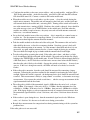
Important Notice
Weidmuller, Inc.’s products are designed to be used in industrial environments, by experienced
industrial engineering personnel with adequate knowledge of safety design considerations.
Weidmuller, Inc. radio products are used on unprotected license-free radio bands with radio noise
and interference. The products are designed to operate in the presence of noise and interference,
however in an extreme case, radio noise and interference could cause product operation delays or
operation failure. Like all industrial electronic products, Weidmuller, Inc.’s products can fail in
a variety of modes due to misuse, age, or malfunction. We recommend that users and designers
design systems using design techniques intended to prevent personal injury or damage during
product operation, and provide failure tolerant systems to prevent personal injury or damage in
the event of product failure. Designers must warn users of the equipment or systems if adequate
protection against failure has not been included in the system design. Designers must include
this Important Notice in operating procedures and system manuals.
These products should not be used in non-industrial applications, or life-support systems, without
consulting Weidmuller, Inc. first.
1.
For WI-GTWY-9-xxx modules, a radio license is not required in most countries,
provided the module is installed using the aerial and equipment configuration described
in the WI-I/O 9-x Installation Guide. Check with your local WI-GTWY-9-xxx
distributor for further information on regulations.
2.
For WI-GTWY-9-xxx modules, operation is authorized by the radio frequency regulatory
authority in your country on a non-protection basis. Although all care is taken in the
design of these units, there is no responsibility taken for sources of external interference.
The WI-I/O 9-x intelligent communications protocol aims to correct communication
errors due to interference and to retransmit the required output conditions regularly.
However some delay in the operation of outputs may occur during periods of interference.
Systems should be designed to be tolerant of these delays.
3.
To avoid the risk of electrocution, the aerial, aerial cable, serial cables and all terminals of
the WI-GTWY-9-xxx module should be electrically protected. To provide maximum
surge and lightning protection, the module should be connected to a suitable earth and the
aerial, aerial cable, serial cables and the module should be installed as recommended in
the Installation Guide.
4.
To avoid accidents during maintenance or adjustment of remotely controlled equipment,
all equipment should be first disconnected from the WI-I/O 9-x module during these
adjustments. Equipment should carry clear markings to indicate remote or automatic
operation. E.g. "This equipment is remotely controlled and may start without warning.
Isolate at the switchboard before attempting adjustments."
5.
The WI-GTWY-9-xxx module is not suitable for use in explosive environments without
additional protection.
5
WI-GTWY-9-xxx Wireless Gateway
Introduction v1.18
How to Use This Manual
To receive the maximum benefit from your WI-GTWY-9-xxx product, please read the
Introduction, Installation and Operation chapters of this manual thoroughly before using the
WI-GTWY-9-xxx.
Chapter Four Configuration explains how to configure the modules using the Configuration
Software available.
Chapter Six Troubleshooting will help if your system has problems.
The foldout sheet WI-GTWY-9-xxx Installation Guide is an installation drawing appropriate for
most applications.
CONTENTS
CHAPTER 1
INTRODUCTION
CHAPTER 2
OPERATION
19
CHAPTER 3
INSTALLATION
29
1.1
OVERVIEW
1.1.1 Modbus / DF1 WI-GTWY-9-MD1
1.1.2 Profibus WI-GTWY-9-PRx
1.1.3 Ethernet WI-GTWY-9-ET1
1.1.4 DeviceNet WI-GTWY-9-DE1
1.1.5 Modbus Plus WI-GTWY-9-M+1
1.2
THE WI-GTWY-9-XXX STRUCTURE
1.2.1 On-board I/O
1.3
THE WIRELESS NETWORK
1.3.1 WI-I/O 9-x to WI-GTWY-9-xxx Network
1.3.2 WI-GTWY-9-xxx to WI-GTWY-9-xxx Network
1.3.3 “Data Concentrator” Networks
1.3.4 WI-GTWY-9-xxx Repeaters
2.1
START-UP
2.2
OPERATION
2.3
DATABASE
2.4
THE HOST - WI-GTWY-9-XXX LINK
2.4.1 Modbus / DF1
2.4.2 Profibus
2.4.3 Ethernet
2.5
RADIO SYSTEM DESIGN
2.5.1 Radio Signal Strength
2.5.2 Repeaters
2.6
RADIO COMMS FAILURE
2.6.1 Monitoring Communications Failure
2.7
SECURITY CONSIDERATIONS
3.1
GENERAL
3.2
ANTENNA INSTALLATION
3.2.1 Dipole and Collinear antennas.
3.2.2 Yagi antennas.
6
9
9
10
11
12
12
13
13
14
15
15
16
17
18
19
19
22
24
24
24
24
25
25
26
26
27
27
29
29
31
32
WI-GTWY-9-xxx Wireless Gateway
User Manual V1.18
3.3
POWER SUPPLY
3.3.1 AC Supply
3.3.2 DC Supply
3.3.3 Solar Supply
3.4
INPUT / OUTPUT
3.4.1 Digital Inputs / Outputs
3.5
SERIAL PORT
3.5.1 RS232 Serial Port
3.5.2 RS485 Serial Port
3.6
PROFIBUS PORT
3.7
ETHERNET PORT
3.8
MODBUS PLUS PORT
3.9
DEVICENET PORT
CHAPTER 4
CONFIGURATION
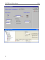
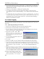
4.1
INTRODUCTION
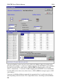
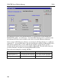
4.2
CONFIGURATION PROGRAM
4.2.1 Program Operation
4.2.2 Security
4.3
UPLOADING AND DOWNLOADING
4.3.1 Loading from a WI-GTWY-9-xxx
4.4
MAPPINGS WI-GTWY-9-XXX TO WI-I/O 9-X I/O MODULES
4.4.1 Mappings from Inputs at Remote WI-I/O 9-x I/O Modules
4.4.2 Mappings from WI-GTWY-9-xxx to Outputs at Remote WI-I/O 9-x I/O Modules
4.4.3 Don’t Send if in Comm Fail
4.4.4 Startup Polls
4.4.5 Polls to Remote Modules
4.5
MAPPINGS FROM WI-GTWY-9-XXX TO OTHER WI-GTWY-9-XXX MODULES
4.5.1 Entering a Block Mapping
4.5.2 Host Device Trigger
4.5.3 Time Period
4.5.4 Real-Time
4.5.5 Change-of-State
4.5.6 Block Read Mappings
4.5.7 Mixing Normal Mappings and Block Mappings
4.5.8 Block mapping to Internal I/O registers
4.5.9 Comms Fail for Block Mappings
4.5.10
“Repeater-only” Configuration
4.6
CHANGE SENSITIVITY & I/O VALUE SCALING
4.6.1 Change Sensitivity
4.6.2 I/O Value Scaling
4.6.3 Unit Details
4.6.4 Number of TX only transmissions
4.6.5 Reset on Buffer Empty (Firmware version 1.83 and later)
4.7
SERIAL CONFIGURATION - MODBUS
4.7.1 MODBUS Slave
4.7.2 MODBUS Master
4.8
SERIAL CONFIGURATION - DF1
4.9
FIELDBUS CONFIGURATION
4.9.1 Fieldbus Mappings
4.10
FIELDBUS CONFIGURATION - PROFIBUS SLAVE
32
33
33
34
35
35
36
36
37
38
39
40
41
42
42
43
44
47
49
50
51
51
52
54
55
55
55
57
58
59
60
62
62
63
63
64
64
65
65
66
69
69
69
70
70
72
75
80
81
87
7
WI-GTWY-9-xxx Wireless Gateway
4.11
FIELDBUS CONFIGURATION - PROFIBUS MASTER
4.11.1
GSD File
4.11.2
Protocol and Supported Functions
4.11.3
Configuration
4.11.4
Configuration Example
4.11.5
Message Interface
4.11.6
DP Return Codes
4.12
FIELDBUS CONFIGURATION - ETHERNET
4.12.1
Setting IP Address
4.12.2
Modbus TCP
4.12.3
EtherNet/IP
4.13
FIELDBUS CONFIGURATION – DEVICENET
4.13.1
DeviceNet Introduction
4.13.2
DeviceNet Address Setting
4.13.3
EDS File
4.13.4
Protocol and Supported Functions
4.14
FIELDBUS CONFIGURATION – MODBUS PLUS
4.14.1
Modbus Plus Introduction
4.14.2
Modbus Plus Addressing
4.14.3
Protocol & Supported Functions
4.14.4
Configuration
4.15
CONNECTING WI-I/O-EX-1-S-1X SERIAL I/O
4.16
ACCESS TO MESSAGE BUFFER COUNT
Introduction v1.18
88
88
88
88
96
99
119
122
122
124
127
131
131
131
131
132
132
132
133
133
134
135
137
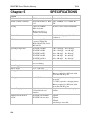
CHAPTER 5
SPECIFICATIONS
138
CHAPTER 6
DIAGNOSTICS
141
CHAPTER 7
WARRANTY
160
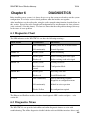
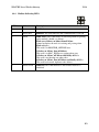
6.1
DIAGNOSTICS CHART
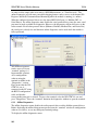
6.2
DIAGNOSTICS MENU
6.3
ETHERNET DIAGNOSTICS
6.4
FIELDBUS INDICATING LEDS
6.4.1 Ethernet Indicating LED’s
6.4.2 Profibus Slave Indicating LED’s
6.4.3 Profibus Master Indicating LED’s
6.4.4 Modbus Indicating LED’s
6.4.5 DeviceNet Indicating LED’s
6.5
RADIO PATH TESTING
6.6
COMMS LOGGING
141
141
148
150
150
151
152
153
154
154
156
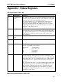
APPENDIX 1 STATUS REGISTERS
161
APPENDIX 2
163
8
IT FUNCTIONALITY
WI-GTWY-9-xxx Wireless Gateway
Chapter 1
User Manual V1.18
INTRODUCTION
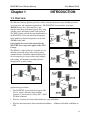
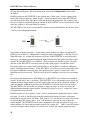
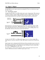
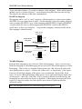
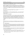
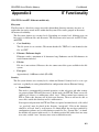
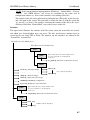
1.1 Overview
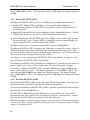
The Wireless Gateway products provide a wireless interface between various fieldbus protocols
used in process and automation applications. The WI-GTWY-9-xxx includes an integral
900MHz license-free radio transceiver, and
WI-I/O 9
transfers transducer and control signals (I/O) using
a highly secure and highly reliable radio protocol.
Direct I/O
The 105U-G units provide the same functionality as Profibus
the WI-GTWY-9-xxx, but with a fixed frequency
Ethernet
radio suitable for licensed frequencies in the 380 –
520 MHz radio band.
Modbus
Functionality discussed in this manual for the
WI-GTWY-9-xxx range also applies to the 105UG range.
The WI-I/O 9-x radio protocol is designed for very
efficient radio band usage, with event reporting
communications, automatic acknowledgment and
error-correction, peer to peer addressing, multiple
path routing, and frequency encoding and data
encryption for system security.
WI-GTWY
DF1
Internet
WI-I/O 9
WI-GTWY
Direct I/O
Ethernet
Profibus
WI-GTWY
Modbus
WI-GTWY
WI-GTWY
WI-GTWY
Profibus
Profibus
Profibus
WI-I/O 9
Direct I/O
Profibus
Application types include:
•
The WI-GTWY-9-xxx interfaces between WII/O 9-x wireless I/O and various fieldbus
protocols. Connect wireless I/O to PLC’s, DCS,
SCADA or Internet.
Ethernet
Modbus
WI-GTWY
Direct I/O
WI-I/O 9
•
Wireless extension of factory automation buses such as Profibus.
•
Wireless interconnectivity between different fieldbuses - Ethernet to Profibus to Modbus to
DF1.
9
WI-GTWY-9-xxx Wireless Gateway
•
Introduction v1.18
Combined networks of the above.
The WI-GTWY-9-xxx has eight on-board discrete I/O. Each I/O point can be configured
individually as a contact input signal, or a discrete output signal. Input signals can be sent via its
fieldbus connection to a host device (PLC, DCS etc) or be transmitted by radio to other WI-I/O
9-x units. The output signals can be driven by a host device, or linked to inputs on remote WII/O 9-x units.
This document assumes the reader is familiar with the operation of the WI-I/O 9-x I/O modules for further information, please refer to the User Manuals for these products.
Ordering information:
WI-GTWY-9-MD1
Modbus Master & Slave / DF1 interface
WI-GTWY-9-PR1
Profibus-DP Slave interface
WI-GTWY-9-PR2
Profibus-DP Master interface
WI-GTWY-9-ET1
Ethernet interface - Modbus TCP, Ethernet IP, FTP, HTML, Email
WI-GTWY-9-DE1
DeviceNet Slave interface
WI-GTWY-9-M+1
Modbus Plus Slave interface
The same ordering codes apply to the WI-GTWY-1 product range.
1.1.1 Modbus / DF1 WI-GTWY-9-MD1
The WI-GTWY-9-MD1 can be configured for Modbus master interface, Modbus slave, or DF1.
Modbus is a Master-Slave protocol originally developed by Modicon (now part of the Schneider
group). It became a popular interconnect protocol with many equipment manufacturers. One
Modbus master controls the Modbus network communications, which can comprise up to 250
Modbus slave devices. The Modbus master can read or write I/O values to/from Modbus slaves.
The WI-GTWY-9-MD1 can be configured as either Modbus Master or Modbus Slave. The
variation of Modbus supported by the WI-GTWY-9-MD1 is “Modbus RTU” (also known as
“Modbus binary”).
DF1 is an Allen-Bradley protocol (Allen-Bradley is now part of the Rockwell Automation
group). DF1 offers both full-duplex (point to point) and half-duplex (multidrop) operation. The
WI-GTWY-9-MD1 only supports the full-duplex operation - this is the default DF1 mode on
most equipment. DF1 full-duplex is a “peer-to-peer” protocol. Either DF1 device can initiate
commands to the other device, and both devices will respond to commands from the other
device.
The WI-GTWY-9-MD1 has two serial connections - RS232 and RS485, on the bottom end plate
of the module. The serial port provides both RS232 and RS485 hardware connections, however
both connections are paralleled internally - both connections cannot be used at the same time.
Either RS232 or RS485 can be used for Modbus communications, however only the RS232
port can be used for DF1. The serial port must be configured to suit the host device. Serial
data rates between 1200 and 19200 baud may be selected, and character types with 7 or 8 data
bits, even/odd/none parity, and 1 or 2 stop bits may be selected.
10
WI-GTWY-9-xxx Wireless Gateway
User Manual V1.18
The Modbus/DF1 WI-GTWY-9-MD1 has 4300 general-purpose I/O registers. Each discrete,
analog and pulse I/O point takes up one register.
1.1.2 Profibus WI-GTWY-9-PRx
The Profibus WI-GTWY-9-PR1 provides Profibus-DP Slave functionality according to EN
50170. Profibus is a popular automation fieldbus that originated in Germany and is used
extensively by Siemens and other automation suppliers.
The Profibus connection on the WI-GTWY-9-PRx is optically isolated RS485 using an on-board
DC/DC converter. The Profibus port has automatic baudrate detection (9600 bit/s - 12 Mbit/s).
The Profibus Slave WI-GTWY-9-PR1 will connect to a Profibus LAN controlled by an external
master device. The Profibus Master WI-GTWY-9-PR2 will control communications on a
Profibus LAN, and can connect to up to 125 Profibus slave devices.
The Profibus WI-GTWY-9-PR2 I/O database has 4300 registers (each of 16 bit value), however
the Profibus interface limits the amount of I/O that can be transferred via the Profibus port.
Slave unit (PR1). The PR1 slave unit only supports 416 x 8 bit bytes of I/O. Of the 416 bytes of
I/O, there is a maximum 244 input bytes and maximum 244 output bytes - that is, if 244 input
bytes are used then only 172 output bytes can be used (416 – 244). Each byte can represent 8
discrete inputs or outputs, or an 8-bit value, or two bytes can represent a 16-bit value. That is,
analog or pulse I/O can be transferred as 8-bit registers (1 byte) or 16-bit registers (2 consecutive
bytes).
An “output” is a value coming into the WI-GTWY-9-PR1 via the fieldbus (that is, a value
written to the WI-GTWY-9-PR1 from the Profibus master). An input is a value going out from
the WI-GTWY-9-PR2 via the fieldbus (a value read by the Profibus master).
So a Profibus Slave WI-GTWY-9-PR1 could handle up to 1952 (244 x 8) discrete inputs or 244
low resolution analog inputs or 122 (244 x ½) high resolution analog inputs, or some
combination in between.
For example, a Profibus WI-GTWY-9-PR1 can handle 400 discrete inputs, 240 discrete outputs,
90 analog inputs and 60 analog outputs (assume analogs are 16-bit). The number of input bytes
is 230 (400/8 + 90*2). The number of output bytes is 150 (240/8 + 60*2). The total number of
I/O bytes is 380. If the number of analog outputs was increased to 90, then the total output bytes
would be 210 (240/8 + 90*2), and the total number of I/O bytes is 440 - this exceeds the
capacity of the Profibus interface.
Master unit (PR2). The Profibus master interface supports 2048 input bytes and 2048 output
bytes. Each byte can be 8 discrete inputs or outputs, but analog or pulse I/O take up 1 byte for
low resolution values (8-bit) or 2 bytes for high resolution values (16-bit).
So a Profibus Master WI-GTWY-9-PR2 can handle up to 4300 I/O total, but analog or pulse
inputs are limited to 2048 x 8-bit values or 1024 x 16-bit values. The same limit applies to
outputs.
For example, a Profibus Master WI-GTWY-9-PR2 can handle 2000 discrete inputs and 500
analog inputs (assume analogs are 16-bit). The number of input bytes is 1250 (2000/8 + 500*2).
The same unit could handle 4000 discrete outputs and 750 analog outputs. The number of output
11
WI-GTWY-9-xxx Wireless Gateway
Introduction v1.18
bytes is 2000 (4000/8 + 750*2). The total number of I/O is 3250 which is less than the total limit
of 4300.
1.1.3 Ethernet WI-GTWY-9-ET1
The Ethernet WI-GTWY-9-ET1 provides several different types of Ethernet functionality:
♦ Modbus TCP. Modbus TCP uses Modbus as a base protocol within an Ethernet
communications structure. The WI-GTWY-9-xxx provides class 0, 1 and partially class 2
slave functionality.
♦ EtherNet IP. EtherNet IP is the version of Ethernet used by Allen-Bradley devices. The WIGTWY-9-ET1 provides level 2 I/O server CIP (ControlNet and DeviceNet).
♦ Internet functionality. The WI-GTWY-9-ET1 has 1.4Mbyte of non-volatile “flash” memory
for embedded web “pages” (dynamic HTTP), on-board file system, user downloadable web
pages through FTP server, and email functionality (SMTP).
The Ethernet connection is a transformer isolated RJ45 connector, 10/100 Mbit/sec.
The Ethernet WI-GTWY-9-ET1 I/O database has 4300 registers (each of 16 bit value), however
the Ethernet interface only supports 2048 input bytes and maximum 2048 output bytes. Each
byte can be 8 discrete inputs or outputs, but analog or pulse I/O take up 1 byte for low resolution
values (8-bit) or 2 bytes for high resolution values (16-bit).
An “output” is a value coming into the WI-GTWY-9-ET1 via the fieldbus. An input is a value
going out from the WI-GTWY-9-ET1 via the fieldbus.
So an Ethernet WI-GTWY-9-ET1 can handle up to 4300 I/O total, but analog or pulse inputs are
limited to 2048 x 8-bit values or 1024 x 16-bit values. The same limit applies to outputs.
For example, an Ethernet WI-GTWY-9-ET1 can handle 2000 discrete inputs and 500 analog
inputs (assume analogs are 16-bit). The number of input bytes is 1250 (2000/8 + 500*2). The
same unit could handle 4000 discrete outputs and 750 analog outputs. The number of output
bytes is 2000 (4000/8 + 750*2). The total number of I/O is 3250 which is less than the total limit
of 4300.
1.1.4 DeviceNet WI-GTWY-9-DE1
The DeviceNet WI-GTWY-9-DE1 provides DeviceNet 2.0 Slave functionality. DeviceNet is an
automation fieldbus developed by Allen-Bradley (Rockwell Automation).
The DeviceNet connection on the WI-GTWY-9-DE1 is optically isolated RS422 with selectable
baudrate between 125 and 500 Kbit/sec.
The WI-GTWY-9-DE1 I/O database has 4300 registers (each of 16 bit value), however the
DeviceNet interface only supports 512 x 8 bit input bytes and 512 x 8 bit output bytes, and this
limits the amount of I/O that can be transferred via the DeviceNet port.
Each byte can represent 8 discrete inputs or outputs, or an 8-bit value, or two bytes can represent
a 16-bit value. That is, analog or pulse I/O can be transferred as 8-bit registers (1 byte) or 16-bit
registers (2 consecutive bytes).
12
WI-GTWY-9-xxx Wireless Gateway
User Manual V1.18
An “output” is a value coming into the WI-GTWY-9-DE1 via the fieldbus (that is, a value
written to the WI-GTWY-9-DE1 from the DeviceNet master). An input is a value going out
from the WI-GTWY-9-DE1 via the fieldbus (a value read by the DeviceNet master).
So a DeviceNet WI-GTWY-9-DE1 can normally handle up to 4096 (512 x 8) discrete inputs or
512 low resolution analog inputs or 256 (512 x ½) high resolution analog inputs, or some
combination in between. It can also handle the same number of outputs; however the total I/O
count cannot exceed the WI-GTWY-9-DE1 database size of 4300.
1.1.5 Modbus Plus WI-GTWY-9-M+1
The Modbus Plus WI-GTWY-9-M+1 provides Modbus Plus Slave functionality. The Modbus
Plus connection on the WI-GTWY-9-M+1 is optically isolated RS485 with standard baudrate of
1 Mbit/sec.
The WI-GTWY-9-M+1 I/O database has 4300 registers (each of 16 bit value), however the
Modbus Plus interface only supports 1024 input registers and maximum 1024 output registers.
Each register can be 16 discrete inputs or outputs, or one analog or counter 16-bit value.
An “output” is a value coming into the WI-GTWY-9-M+1 via the fieldbus. An input is a value
going out from the WI-GTWY-9-M+1 via the fieldbus.
So an Modbus Plus WI-GTWY-9-M+1 can handle up to 4300 I/O total, but analog or pulse
inputs are limited to 1024 x 16-bit values. The same limit applies to outputs.
The Modbus Plus interface allows global data base transactions with routing for up to six
Modbus Plus networks.
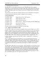
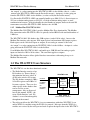
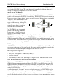
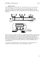
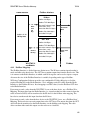
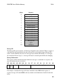
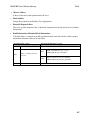
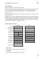
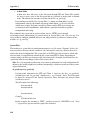
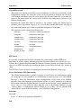
1.2 The WI-GTWY-9-xxx Structure
The WI-GTWY-9-xxx has three functional sections:
• The Radio Interface consists of an
I/O database (or "Process Image")
that maintains the latest values of
all I/O in the wireless I/O system.
The I/O database comprises 4300 x
16 bit I/O registers and 4300 x 16
bit status registers. There are also
other registers in the database that
can be used for system
management - they are discussed
later in this manual. NOTE – the
terms ‘Radio Interface’ and ‘I/O
database’ are used interchangeably
throughout the manual.
WI-GTWY-9-xxx
• The radio port allows the WI-GTWY-9-xxx to communicate with other WI-GTWY-9-xxx
and/or WI-I/O 9-x modules using the WI-I/O 9-x protocol. Messages from the WI-I/O 9-x
modules are received by the radio port and used to update the input values in the WI-GTWY13
WI-GTWY-9-xxx Wireless Gateway
Introduction v1.18
9-xxx Radio Interface. The radio port also creates the correct radio message to set outputs on
the remote WI-I/O 9-x modules.
The WI-I/O 9-x protocol is an extremely efficient protocol for radio communications. Radio
messages can be sent using exception reporting - that is, when there is a change of an input
signal - or by read/write messages. Each message can comprise a single I/O value, or multiple
I/O values (termed a “block” of I/O). There are also update messages, which are sent for
integrity purposes. Messages include error checking, with the destination address sending a
return acknowledgment. Up to five attempts are made to transmit the message if an
acknowledgment is not received. The WI-I/O 9-x protocol is designed to provide reliable
radio communications on an open license-free radio channel.
• The Fieldbus port enables communications between a host device, which could be a PLC,
DCS, HMI, intelligent transducer, etc), and the WI-GTWY-9-xxx Radio Interface database. A
“host device” may be one or several devices connected to the same fieldbus or network (for
example, an Ethernet LAN) - in this manual, the LAN is considered as a “host device”.
The fieldbus port decodes messages from the host device and reads or writes I/O values to the
database. The fieldbus port can also generate messages to the host device.
The WI-GTWY-9-xxx I/O database effectively isolates the fieldbus and the radio network. This
provides a high level of system performance. The WI-I/O 9-x radio protocol is very efficient and
reliable for radio communications. It minimizes radio channel usage by "change-of-state"
reporting, and allows the use of intermediate repeater addresses. It also allows peer-to-peer (WII/O 9-x to WI-I/O 9-x, WI-GTWY-9-xxx to WI-GTWY-9-xxx) and peer-to-master (WI-I/O 9-x
to WI-GTWY-9-xxx) communications. PLC protocols, by comparison, are designed to provide
transfer of large I/O files by "wire" link. The WI-GTWY-9-xxx retains the advantage of both
protocols in their respective communications media.
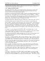
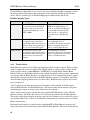
1.2.1 On-board I/O
The WI-GTWY-9-xxx has eight on-board discrete I/O. Each I/O point can be used as either a
discrete input (voltage free contact input) or discrete output (transistor output) - an I/O point
cannot be used as both input and output. Each I/O point is linked to two separate I/O registers in
the database - one for the “input” function and one for the “output” function.. If the output
register is set “on” by the fieldbus or by a radio message from a remote module, then the WIGTWY-9-xxx will automatically set the input register for the same I/O point to “off”. This means
that the output register has priority over the input register - if there is a conflict, the input value is
ignored.
The WI-GTWY-9-xxx also has three internal inputs linked to I/O registers:
♦ Supply voltage status - if the normal supply fails, this status is set on.
♦ Low battery voltage. The WI-GTWY-9-xxx has an internal battery charger to trickle charge a
back-up battery. If the battery voltage is low, this status is set.
♦ Battery voltage - the actual value of the connected battery voltage.
1.2.2
14
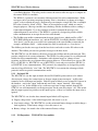
I/O Expansion - WI-I/O-EX-1-S-xx modules
WI-GTWY-9-xxx Wireless Gateway
User Manual V1.18
Where additional discrete or analog I/O is required, an external expansion I/O module can be
connected to the RS485 port of the WI-GTWY-9 module. See section 4.15 for more details on
this.
Note: Serial Expansion modules can only be used with the WI-GTWY-9-MD1 unit under
certain circumstances.
•
WI-GTWY-9-MD1 is configured as “Repeater-only”
•
WI-GTWY-9-MD1 is configured as a Modbus Master and WI-I/O-EX serial expansion
modules are used as Modbus Slaves.
WI-I/O 9
The WI-I/O-EX modules have the ability to be
configured to communicate the same way as a WII/O-9 module using the WIB-net Protocol or via as
a Modbus Slave communicating Modbus RTU
WI-GTWY
protocol. They can be setup with an address range
of 1-99, which is selectable via the rotary switches
on end plate of the module.
WI-I/O 9-K
WI-I/O 9
WI-I/O-9
1.3 The Wireless Network
The WI-GTWY-9-xxx can communicate with up to 490 other addresses - this could be 490 other
WI-I/O 9-x modules, or in the case of WI-I/O 9-K modules, it could be many thousands of
modules (as many WI-I/O 9-K modules can share the same address). WI-GTWY-9-xxx modules
may take up more than one address under some circumstances.
Any WI-GTWY-9-xxx or WI-I/O 9-x module can act as a radio repeater for other modules - that
is, radio messages can be passed onto other modules. Up to five repeater addresses can be
configured for messages transmitted to a WI-GTWY-9-xxx module.
Each module can have a unit address between 1 – 95, but the WI-GTWY-9-xxx also recognizes
repeater addresses in conjunction with the unit address as the module “identifier”. Hence module
#2 is recognized as different to #2 via #57 - #57 being a repeater.
1.3.1 WI-I/O 9-x to WI-GTWY-9-xxx Network
In the wireless I/O system, the WI-GTWY-9-xxx acts as a normal WI-I/O 9-x module (this
covers WI-I/O 9-x I/O, WI-I/O-EX-1-S-1x I/O, WI-I/O 9-x-K and WI-I/O 9-x-C modules).
WI-I/O 9-x modules transmit messages to the WI-GTWY-9-xxx address and the WI-GTWY-9xxx acknowledges these messages like a normal WI-I/O 9-x module. When a WI-GTWY-9-xxx
transmits messages to change remote outputs, it will "re-try" if it does not receive an
acknowledgment, like a normal WI-I/O 9-x module.
Remote WI-I/O 9-x modules can connect to WI-I/O-EX-1-S-1x modules in the normal way. The
WI-GTWY-9-xxx host can access I/O on WI-I/O-EX-1-S-1x modules by using the intermediate
WI-I/O 9-x as a repeater.
15
WI-GTWY-9-xxx Wireless Gateway
Introduction v1.18
WI-I/O 9-x modules can transmit input messages directly to outputs on other WI-I/O 9-x module,
as well as the WI-GTWY-9-xxx. The same input can be transmitted to different addresses by
entering two "mapping" configurations at the remote module.
Normal WI-I/O 9-x Messages
I/O registers in a WI-GTWY-9-xxx can be configured (mapped) to outputs at remote WI-I/O 9-x
modules, or I/O registers in WI-GTWY-9-xxx modules. The WI-GTWY-9-xxx will transmit an
I/O message when a “change-of-state” occurs for that I/O register. Registers have a configurable
“sensitivity” value - this determines how
WI-I/O 9
much the register value has to change to
trigger a change message. A change-ofstate occurs when the register value has
PLC
PLC
changed by more than the sensitivity
WI-GTWY
value since the last transmission.
WI-GTWY
The WI-GTWY-9-xxx also transmits
periodic update messages if there has
WI-I/O
been no change - if an I/O register is
mapped to a remote output or another
WI-GTWY-9-xxx, then that register can be configured with an update time.
WI-GTWY-9-xxx modules can transmit to WI-GTWY-9-xxx modules as well as other WIGTWY-9-xxx modules. There can be multiple WI-GTWY-9-xxx modules in a network - as well
as WI-I/O 9-x I/O. Because the WI-I/O 9-x protocol is peer-to-peer, there are few constraints on
communications between multiple WI-I/O 9-x modules.
Poll Messages
A WI-GTWY-9-xxx can also generate poll messages to remote WI-I/O 9-x modules. These poll
messages act in the same way as a start-up poll - the remote module immediately responds with
update messages for any I/O mappings configured to the WI-GTWY-9-xxx.
Poll messages can be triggered by:
♦ time period, configurable 1 – 4096 sec (1.1 hour), or
♦ real time clock, or
♦ on demand by the host device, by writing to a “trigger register” in the WI-GTWY-9-xxx
1.3.2 WI-GTWY-9-xxx to WI-GTWY-9-xxx Network
Different types of WI-GTWY-9-xxx modules can communicate - for example, a Modbus WIGTWY-9-xxx can communicate with an Ethernet WI-GTWY-9-xxx. I/O registers in one WIGTWY-9-xxx can be transmitted to I/O registers in another WI-GTWY-9-xxx. When the WIGTWY-9-xxx is configured, “mappings” can be entered linking I/O registers to registers in
another WI-GTWY-9-xxx.
As well as the normal “I/O change” messages and update messages, the WI-GTWY-9-xxx has
“block read” and “block write” messages for use with other WI-GTWY-9-xxx modules. These
messages will transmit multiple register values instead of only one as in the normal WI-I/O 9-x
message. The block read/write messages increase the efficiency of radio communications where a
16
WI-GTWY-9-xxx Wireless Gateway
User Manual V1.18
WI-GTWY-9-xxx “sees” a large number of changes in its database at the one time. For
example, if a host writes a block of 100 signal values to a WI-GTWY-9-xxx, and 20 of these
values have changed since the last write-operation. If the block is mapped to another WIGTWY-9-xxx, then the WI-GTWY-9-xxx can transmit all 20 values in one radio message,
instead of 20 messages.
Normal I/O messages can be repeated by any type of WI-I/O 9-x I/O module, however block
read/write messages can only be repeated by other WI-GTWY-9-xxx modules.
Block Read Message
A block read message is a request to another WI-GTWY-9-xxx to transmit the values of a
consecutive block of registers. The destination WI-GTWY-9-xxx will respond with the values,
which will be stored in a corresponding block of registers in the originating WI-GTWY-9-xxx.
A block read message can be triggered by:
♦ time period, configurable 1 – 4096 sec (1.1 hour), or
♦ real time clock, or
♦ on demand by the host device, by writing to a “trigger register” in the WI-GTWY-9-xxx.
Block Write Message
A block write message transmits a consecutive block of register values from one WI-GTWY-9xxx to a destination WI-GTWY-9-xxx. It can be triggered by:
♦ time period, configurable 1 – 4096 sec (1.1 hour), or
♦ real time clock, or
♦ on demand by the host device, by writing to a “trigger register” in the WI-GTWY-9-xxx, or
♦ a change-of-state event occurring within the block of I/O registers.
If a block write message has been configured to be transmitted on change-of-state, a “time
window” is configured. When a change-of-state occurs in one of the registers in the block, the
time window will be activated. All changes during the time window will be grouped together
and transmitted as one block write message. That is, the block write message will not be sent
immediately the first change-of-state occurs (unless the time window is configured to zero), but
will be sent at the end of the time window - any other registers in the block that change during
the time window will be sent as part of the same message. The time window can be configured
from 0 – 255 seconds.
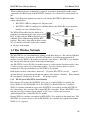
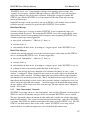
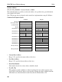
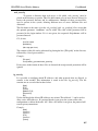
1.3.3 “Data Concentrator” Networks
WI-GTWY-9-xxx units can act as “data concentrator” units to collect I/O from a local network of
WI-I/O 9-x wireless I/O modules and pass the I/O on to another WI-GTWY-9-xxx as a block.
This type of network reduces the amount of radio traffic and is suitable for systems with a large
number of I/O modules. The system is divided into local sub-networks, each with a WI-GTWY9-xxx unit. The WI-I/O 9-x modules transmit their I/O vlaues to the WI-GTWY-9-xxx. The WIGTWY-9-xxx then transfers these values to the “central” WI-GTWY-9-xxx using a block
transfer which is very efficient compared to a lot of individual I/O transmissions.
17
WI-GTWY-9-xxx Wireless Gateway
Introduction v1.18
The data concentrator network is different than using the WI-GTWY-9-xxx as a repeater. A
repeater re-transmits each message in the same format. A data concentrator collects the I/O
values as a block, and transmits the complete block in one transmission.
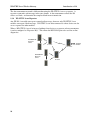
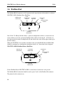
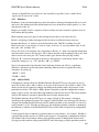
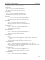
1.3.4 WI-GTWY-9-xxx Repeaters
Any WI-I/O 9-x module can repeat a normal radio message, however only WI-GTWY-9-xxx
modules can repeat a block message. WI-GTWY-9-xxx units connected to a host device can also
act as a repeater for other modules.
Where a WI-GTWY-9-xxx is being used without a host device as a repeater or data-concentrator,
it can be configured as “Repeater-only”. This allows the RS232/485 port to be used for on-line
diagnostics
NETWORK OF
WI-I/O 9-x
UNITS
TO HOST
DEVICE
WI-GTWY
WI-GTWY
NETWORK OF
WI-I/O 9-x
UNITS
WI-GTWY
18
WI-GTWY-9-xxx Wireless Gateway
Chapter 2
V1.18
OPERATION
2.1 Start-up
The WI-GTWY-9-xxx operating software and the database configuration are stored in nonvolatile memory; however the database I/O register values are lost on power failure (in the same
way as a PLC).
On start-up, the WI-GTWY-9-xxx sends "start-up poll" messages to remote modules based on
the source address of inputs configured in the database (the start-up messages can be disabled by
configuration). The remote modules respond with update messages for their inputs, which sets
initial values in the WI-GTWY-9-xxx I/O database registers. The WI-GTWY-9-xxx provides a
delay of 5 seconds between each start-up poll, to allow the remote module to respond and to
avoid overloading the radio channel.
If there are a lot of remote modules, then this start-up stage may take a significant time, and this
should be allowed for in the system design. The WI-GTWY-9-xxx has an internal battery
charger feature and the use of a back-up battery should be considered if this start-up delay
presents a constraint to system reliability. Start-up polls may be disabled for individual remote
modules in the database configuration.
For the host device, the WI-GTWY-9-xxx provides an "Active" signal on the RS232 port (DCD
pin 1). Its purpose is to indicate to the host that the WI-GTWY-9-xxx is now processing output
messages for the remote modules. When the WI-GTWY-9-xxx powers down (or should an
internal fault occur), the "Active" signal resets (turn “off” or “0”). When the WI-GTWY-9-xxx
starts-up, it holds the "Active" signal in a reset condition (“off” or “0”) for a time equal to the
number of remote addresses (or modules) configured times 5 seconds plus any delay if remote
addresses are offline. For example, if there are 20 remote addresses configured in the WIGTWY-9-xxx database, then the “active” signal will be held in the reset state for 100 seconds
(20 x 5). During this period, the WI-GTWY-9-xxx will not change any output values in its
database. After this time, the WI-GTWY-9-xxx will set the "Active" signal (to “on” or “1”) - the
host can then send messages to the WI-GTWY-9-xxx to update the output values in the database.
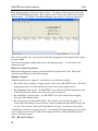
2.2 Operation
The WI-GTWY-9-xxx database can hold values for 4300 I/O signals plus the 8 on-board I/O.
The database registers (also called I/O registers) can be accessed by both the radio port and the
fieldbus port. The host device can change values in the database via the fieldbus, and the WIGTWY-9-xxx can transmit radio messages out with the new values. Radio messages can be
received with new values for database registers, and these new values can be written to the host
device or read by the host device, via the fieldbus.
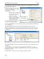
The WI-GTWY-9-xxx operation must be configured before the WI-GTWY-9-xxx will function.
Configuration is achieved by creating a configuration file on a PC and downloading this file to
the WI-GTWY-9-xxx. The WI-GTWY-9-xxx configuration may also be "uploaded" to a PC for
19
WI-GTWY-9-xxx Wireless Gateway
V1.18
viewing and modification. For more information, refer to the Configuration section of this
document.
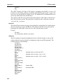
Each I/O register in the WI-GTWY-9-xxx database has a 16-bit value. It doesn’t matter if the
remote I/O is digital (discrete), analog or pulse. The host protocol driver in the WI-GTWY-9xxx will convert the 16 bit value into a value that the host will understand. For example, if the
host device requests a binary/digital read command, the WI-GTWY-9-xxx will convert the 16 bit
value into a binary (1 bit) value before it responds.
The WI-GTWY-9-xxx is able to scale the I/O value between the I/O database and the host device
- this is a user-configurable function.
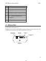
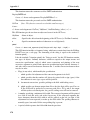
#14
#1
DIN1
WI-I/O 9-x-1
WI-GTWY-9
An example of normal operation - assume that a remote module has address 14 and the WIGTWY-9-xxx is address 1. Module #14 is configured with a mapping DI1 → I/O Reg 76 at #1.
When DI1 turns "on", module #14 transmits a message. If the WI-GTWY-9-xxx can hear this
message, it will transmit an acknowledgment back to module #14, and updates the value of I/O
register 76 in the WI-GTWY-9-xxx database. The host device can read I/O register 76 via the
data-bus, or the WI-GTWY-9-xxx may write the value of I/O register 76 to the host device.
I/O registers that receive values from other WI-I/O 9-x or G modules via radio are configured
with a “Communications fail time”. If the WI-GTWY-9-xxx does not receive a message for this
I/O register within the comms-fail time, then the I/O register is given a “comms fail” status
which the host device can read. The I/O value can also be configured to reset to zero on commsfail.
I/O registers that transmit out to other WI-I/O 9-x or WI-GTWY-9xxx modules are configured
with an “update time” and a “sensitivity”. The WI-GTWY-9-xxx will transmit a message to the
configured remote output whenever the I/O register value changes by the sensitivity amount – if
it has not changed within the update time, the WI-GTWY-9-xxx will send a message anyway.
The WI-GTWY-9-xxx will make five attempts to send a message - if it does not receive an
acknowledgment from the remote module, then the I/O register is given a “comms fail” status
which the host device can read.
Each I/O register has an associated “status” register, which includes information such as commsfail status. As well as each I/O register having an individual comms-fail status, each remote
module has an overall comms fail status. This status is “set” (on) whenever a comms-fail occurs
for an individual I/O register, and is “reset” (off) whenever a message is received from the
remote module. The WI-GTWY-9-xxx can be configured to not send any update messages to a
remote module if it senses that the remote module is in “comms fail” - that is, if any I/O register
associated with the remote module is in “comms fail”. It will start sending update messages
20
WI-GTWY-9-xxx Wireless Gateway
V1.18
again when the WI-GTWY-9-xxx receives a message from the remote module. The default
configuration is that output updates ARE sent during comms fail conditions.
21
WI-GTWY-9-xxx Wireless Gateway
V1.18
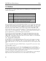
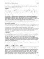
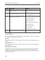
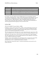
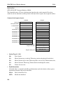
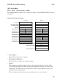
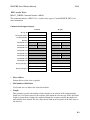
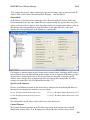
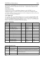
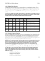
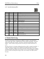
2.3 Database
The WI-GTWY-9-xxx database (Radio Interface) has 10 000 registers, each of 16 bit size. The
structure of the database is:
Registers
Purpose
0 - 4299 I/O registers
4300 - 4399 On-board I/O
4401 - 4499 Comms-fail status and radio strengths for remote modules
5000 - 9499 Status registers - 16 bit status for each I/O signal
9500 - 9999 Status registers for block read/write messages
The register numbers may be used by the Host Protocol Driver to access I/O values and I/O status
information. Each configured I/O point has a 16 bit value (in registers 0000 - 4299), and a 16 bit
status value. The status register is located at 5000 plus the I/O value register. For example, an
I/O point in register number 2560 has a status value in register number 7560 (5000 + 2560).
Details of the status register are provided in Appendix A. The most important part of the status
register is the 15th or most significant bit - this indicates comm-fail status for the I/O register. If
the most significant bit is set, then the I/O register is in comms-fail.
The host device can read the status registers. For example, the communications status of an
output configured at register number 3001 can be examined by reading register number 8001
(5000 + 3001). If the register value is greater than 32767, then the 15th bit is set, indicating that
the output has a communications failure.
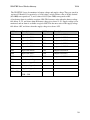
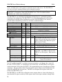
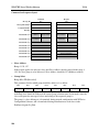
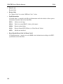
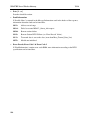
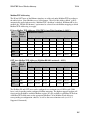
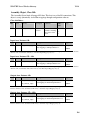
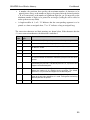
2.3.1 On-board I/O and Internal I/O
The WI-GTWY-9-xxx has eight discrete I/O points. These may be used as inputs or as outputs.
Inputs are linked to registers 4300-4307. That is, if a contact connected to DIO1 is “on”, then
register 4300 is given an “on” value. The inverse of the input values are stored in registers 43704377.
Outputs are controlled from registers 4320-4327; that is, if register 4327 is set to an “on” value,
then output DIO8 is activated.
Whenever an output register is set “on”, the corresponding input register is automatically set
“off”. For example, if register 4321 is set to “1”, the WI-GTWY-9-xxx will also set 4301 to “0”.
This means that if both the input and output registers corresponding to the same I/O point are
used in the configuration, then the output register has priority.
Outputs may be written to by either the host device or by a remote WI-I/O 9-x via the radio port.
Input values can be sent to the host device or to a remote module via the radio port.
22
WI-GTWY-9-xxx Wireless Gateway
V1.18
The WI-GTWY-9-xxx also monitors its battery voltage and supply voltage. These are stored in
registers 4310 and 4311 respectively, as 16 bit values, scaled so that a value of 16384 decimal
(hex 4000) corresponds to 8 V, and a value of 49152 (hex C000) corresponds to 40V.
A low battery alarm is available at register 4308. This becomes active when the battery voltage
falls below 11.3V, and clears when the battery voltage rises above 11.8V. Supply voltage is also
monitored, and an alarm is available at register 4309. This becomes active if the supply voltage
falls below 8.0V, and clears when the supply voltage rises above 9.0V.
I/O Register
Description
I/O Register
Description
4300
Input value DIO 1
4320
Output value DIO 1
4301
Input value DIO 2
4321
Output value DIO 2
4302
Input value DIO 3
4322
Output value DIO 3
4303
Input value DIO 4
4323
Output value DIO 4
4304
Input value DIO 5
4324
Output value DIO 5
4305
Input value DIO 6
4325
Output value DIO 6
4306
Input value DIO 7
4326
Output value DIO 7
4307
Input value DIO 8
4327
Output value DIO 8
4308
Low battery voltage status
4309
Supply voltage fail status
4310
Battery voltage value
4311
Supply voltage value
4370 - 4379
Inverse values of
4300 - 4309
23
WI-GTWY-9-xxx Wireless Gateway
V1.18
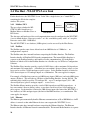
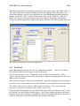
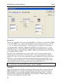
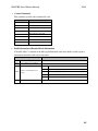
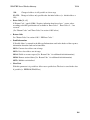
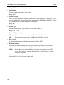
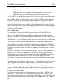
2.4 The Host - WI-GTWY-9-xxx Link
For the host device, the WI-GTWY-9-xxx "looks" like a single device (or a "virtual PLC"),
containing the I/O for the complete
wireless I/O system.
2.4.1 Modbus / DF1
The user selects whether the WIGTWY-9-MD1 should act as a
Modbus Master or Modbus Slave or
DF1 device.
DATA-BUS
DATABASE
I/O
"VIRTUAL PLC"
“HOST DEVICE”
The data type and baud rate of the serial communications must be configured at the WI-GTWY9-xxx to match the host. Data types can be 7 or 8 bit, even/odd/no parity, with 1 or 2 stop bits.
Data rates can be 300 - 19200 baud.
The full WI-GTWY-9-xxx database (4300 registers) can be accessed by the Host Device.
2.4.2 Profibus
The Profibus port has auto-detect of baud rate from 9600 bits/sec to 12Mbit/sec - no
configuration is required.
The Profibus units have internal hardware comprising the Profibus Interface. The Profibus
Interface handles all Profibus DP Network communications. The internal Radio Interface is
separate to the Profibus Interface, and handles all radio communications. I/O in the Radio
Interface is linked to I/O in the Profibus Interface in a flexible way via WI Series Configuration
Software.
The Profibus Slave interface provides a total of 416 I/O bytes, with a maximum 244 input bytes
and maximum 244 output bytes. A Profibus byte can contain 8 discrete (binary) values, or two
bytes can be used for a 16-bit analogue or pulse register. So the Profibus interface is limited to
1952 discrete inputs or 122 analogue inputs or a combination. The same applies for outputs.
For example, a Profibus host wants to read 800 discrete inputs (100 bytes) and write 400 discrete
outputs (50 bytes). This will take up 150 bytes of the Profibus Interface, leaving 266 left. The
remaining bytes could be used for 133 analogue I/O - up to 72 analogue inputs (244 – 100
discrete input bytes) plus 61 analogue outputs - or vice-versa.
The Profibus Master interface provides a total of 2048 input bytes and 2048 output bytes. A
byte can contain 8 discrete (binary) values, or two bytes can be used for a 16-bit analogue or
pulse register. So the interface is limited to 4300 discrete inputs (the limit of the WI-GTWY-9xxx database) or 1024 analogue inputs (the limit of the HMS interface) or a combination. The
same applies for outputs.
2.4.3 Ethernet
The Ethernet port automatically handles Ethernet communications at 10 or 100 Mbit/sec. An IP
address is entered so that other Ethernet devices can recognize the WI-GTWY-9-xxx.
The Ethernet units have internal hardware comprising the Ethernet Interface. The Ethernet
Interface handles all Ethernet Network communications. The internal Radio Interface is separate
24
WI-GTWY-9-xxx Wireless Gateway
V1.18
to the Ethernet Interface, and handles all radio communications. I/O in the Radio Interface is
linked to I/O in the Ethernet Interface in a flexible way via WI Series Configuration Software.
The Ethernet Interface provides a total of 2048 input bytes and 2048 output bytes. An Ethernet
byte can contain 8 discrete (binary) values, or two bytes can be used for a 16-bit analog or pulse
register. So the Ethernet Interface is limited to 4300 discrete inputs (the limit of the WI-GTWY9-xxx database) or 1024 analog inputs (the limit of the Ethernet interface) or a combination. The
same applies for outputs.
For example, an Ethernet host wants to read 500 analog inputs (1000 bytes). The remaining
input bytes (1548) could be used for 12,384 discrete inputs - but the WI-GTWY-9-xxx database
is not this big. Provided there are no outputs required, there could be 3800 discrete inputs (4300
– 500 analogs). If there are outputs required, then the number of discrete inputs available will be
further limited.
2.5 Radio System Design
Each wireless I/O system can have up to 95 unit addresses, although up to 255 WI-I/O 9-K
module can share the same unit address (refer to WI-I/O 9-K User Manual).
Each WI-I/O 9-x module can have up to 31 x WI-I/O-EX-1-S-1x modules connected to it. These
modules are addressed 96 - 127. More than one WI-I/O-EX-1-S-1x module can have the same
address, provided they are not connected to the same WI-I/O 9-x module - that is, #100 via #16
is identified as a different module to #100 via #65.
A constraint that needs to be considered is the capacity of the radio channel. If there is too much
traffic on the radio channel, then the system quickly becomes unreliable. The recommended
maximum average traffic density is 100 messages per minute provided all radio paths are
reliable. If there are marginal radio paths, resulting in re-tries of transmitted messages, then the
maximum traffic density is reduced considerably. Each block read/write messages should be
counted as two messages because of the length of these messages.
A WI-GTWY-9-xxx can be used as a repeater module for messages between other modules.
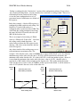
2.5.1 Radio Signal Strength
The WI-GTWY-9-xxx records the radio signal strength of remote modules that communicate
directly (that is, not via repeaters). There are 95 database registers (4401 – 4495) which store the
radio strengths – corresponding to remote addresses #1 - #95. The radio strength (RSSI) is
measured in dBm (relative to 1mW of RF power). The RSSI value is stored in the 8 least
significant bits of each register - a value of –84 dBm would be stored as decimal 84.
These database registers will hold the strength of the last message received from the address. If a
message is received from a remote module via a repeater, then the measurement is recorded in
the address of the last repeater. For example, if a message is received from #24 directly, then the
RSSI will be recorded in register 4424. If a message is received from #24 via #25, then the RSSI
is recorded in register 4425. The WI-GTWY-9-xxx will not know what the radio strength of the
message from #24 to #25 is. If #25 is another WI-GTWY-9-xxx, then it can record this RSSI
and this register could be mapped to an I/O register in the first WI-GTWY-9-xxx.
25
WI-GTWY-9-xxx Wireless Gateway
V1.18
The RSSI registers can be read by the host device, or mapped to I/O registers in other WIGTWY-9-xxx modules.
The first half of the register (8 most significant bits) will be decimal 0 (hex 00) if the remote
module has active communications. If a comms fail status to this address occurs, the most
significant bit will be set. For example, if the last message received from #38 is –99dBm, then
the 16 bit value of register 4438 will be decimal 99 or hex 0063. If the “comms fail” status for
#38 is set, the 16 bit value of register 4438 will become decimal 32,867 (32768 + 99) or hex
8063.
2.5.2 Repeaters
Radio paths may be extended by using intermediate modules as repeaters. A repeater will
receive and re-transmit the radio message. Up to five repeater addresses can be configured that is, a radio message can pass through five intermediate modules. For normal I/O messages,
any WI-I/O 9-x module (except WI-I/O 9-x-K modules) can be used as a repeater, however for
block read/write messages, only WI-GTWY-9-xxx modules can act as repeaters.
2.6 Radio Comms Failure
The WI-GTWY-9-xxx has an internal "communications failure" (comms fail) status for each I/O
point in its database. There is also a comms fail status for each module with direct
communications - see 2.5.1 above.
For I/O registers which are mapped to a remote output or another WI-GTWY-9-xxx, the comms
fail status is set if the WI-GTWY-9-xxx does not receive an acknowledgment for a message
being sent to that remote output. The comms fail status resets when a successful transmission
occurs.
For I/O registers which have been mapped , from a remote input or another WI-GTWY-9-xxx, a
comms fail time period may be configured. If a radio message for this I/O register has not been
received within this time, then this registers comms fail status is set. The comms fail status will
reset when a message is received for this register. If the comms fail time is configured as zero,
then the comms fail status will never be activated. Registers can be configured to reset (go back
to a value of zero) on comms fail.
The communications failure status is bit 15 of the status register for each I/O point. If the host
device reads a register as a digital or binary value, then the WI-GTWY-9-xxx returns bit 15 of
the register (0 or 1) - this is the comms fail bit of a status register.
It is important to use the comms fail status in the overall system design, as any system can fail.
The WI-GTWY-9-xxx also provides an additional comms failure feature to stop the WI-GTWY9-xxx transmitting output messages to an individual remote address if the WI-GTWY-9-xxx
already knows that this remote address is in communication failure. This prevents the WIGTWY-9-xxx from congesting the radio channel with a lot of unnecessary transmissions (and retransmissions). This function is called "Don’t Send if In Comm Fail" and is configurable by the
user for each individual remote address. The WI-GTWY-9-xxx retains a "remote address comms
fail" status for the remote addresses configured for this function. If any output with this remote
26
WI-GTWY-9-xxx Wireless Gateway
V1.18
address goes into communications failure, then the remote address comms fail status is set ("on"
or 1) - every time an input with this remote address receives a radio message, then the remote
address comms fail status is reset ("off" or 0). While the remote address comms fail status is set,
the WI-GTWY-9-xxx disables any output messages being sent to this remote address.
When this feature is configured, all output transmissions are stopped if communications with a
remote module fails for a short period. They will start again when an input message from this
module is received. If the WI-GTWY-9-xxx determines that a output message should be sent to
an output which is disabled because of this feature, then the output message will not be sent and
the comms fail status of that output is set ("on" or 1).
If it is desired to use this function with a remote WI-I/O 9-x module, but there are no inputs from
this module being used, then it is easy to configure an unused input or an internal input (mains
fail or low battery voltage etc). It is the comms fail status for the input, which is used, not the
input itself.
2.6.1 Monitoring Communications Failure
The host device can monitor the communications status of an I/O point by reading the status
register for this point as a binary/discrete register. Modbus, and many other protocols, will
convert a 16 bit register value to a binary/discrete value by returning the most significant bit for the status register, this corresponds to the comms status bit.
For example, to monitor the comms status of I/O register 1045, perform a binary/discrete read on
register 6045 (the status register for 1045). A value of “1” will be returned if this I/O point is in
comms fail, and a “0” returned if the status is normal.
If it is desired to monitor the comms status of all I/O points, it is more efficient to only monitor
the comms status of one I/O point at each remote module (if this point is in comms fail, then all
points at the remote module will be in comms fail). If this point is an input, then the comms fail
time for this input can be made short, to give an early warning of a comms problem (this means
that the corresponding update time for the input at the WI-I/O 9-x will need to be short). If the
point is an output, then the update time for the output should be made short.
2.7 Security Considerations
There are three dimensions of security considerations:
1. Failure to operate when required - or “operational reliability”.
The features discussed above optimize operating reliability. Using an acknowledgment and
re-try protocol ensures that the transmitting module is aware whether the transmitted message
has been transmitted reliably. The “comms fail” alarms provide indication if the radio link
has failed to operate.
2. Mal-operation, or operating when not requested.
This problem occurs when an output is “triggered” by the wrong radio device. The WIGTWY-9-xxx modules use frequency encoding and a very secure addressing system to
27
WI-GTWY-9-xxx Wireless Gateway
V1.18
ensure this does not occur. An additional security level using data encryption can also be
selected.
3. Malicious operation, or “hacking”
This is the problem most associated with security concerns - the ability for someone to
access information from a radio system by “listening-in”, or to cause damage by transmitting
radio messages to force outputs.
A security option can be selected during the module configuration to protect against this. The
security option (if selected) adds data encryption to radio messages. Modules in the same
system are automatically configured with the encryption key, such that only these modules
can understand each other. “Foreign” modules will hear the messages, but cannot decrypt the
messages. For more information, refer to section 4.2.2.
28
WI-GTWY-9-xxx Wireless Gateway
Chapter 3
V1.18
INSTALLATION
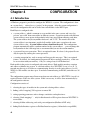
3.1 General
The WI-GTWY-9-xxx module is housed in a rugged aluminum case, suitable for DIN-rail
mounting. Terminals will accept wires up to 12 gauge (2.5 sqmm) in size.
All connections to the module must be low voltage (SELV). Normal 110-240V mains supply
should not be connected to any terminal of the WI-GTWY-9-xxx module. Refer to Section
3.3 Power Supply.
Before installing a new system, it is preferable to bench test the complete system. Configuration
problems are easier to recognize when the system units are adjacent. Following installation, the
most common problem is poor communications caused by incorrectly installed aerials, or radio
interference on the same channel, or the radio path being inadequate. If the radio path is a
problem (i.e. path too long, or obstructions in the way), then higher performance aerials or a
higher mounting point for the aerial may rectify the problem. Alternately, use an intermediate
WI-I/O 9-x Module as a repeater.
The foldout sheet WI-GTWY-9-xxx Installation Guide provides an installation drawing
appropriate to most applications. Further information is detailed below.
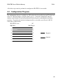
Each WI-GTWY-9-xxx module should be effectively earthed/grounded via the "GND" terminal
on the WI-I/O 9-x module - this is to ensure that the surge protection circuits inside the module
are effective.
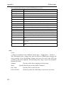
3.2 Antenna Installation
The WI-GTWY-9-xxx and WI-I/O 9-x modules will operate reliably over large distances. The
distance which may be reliably achieved will vary with each application - depending on the type
and location of antennas, the degree of radio interference, and obstructions (such as hills or trees)
to the radio path. Typical reliable distances are :
USA/Canada 15 miles
6dB net gain antenna configuration permitted (4W ERP)
Australia/NZ 12 km
unity gain antenna configuration (1W ERP)
Longer distances can be achieved if one antenna is mounted on top of a hill.
To achieve the maximum transmission distance, the antennas should be raised above
intermediate obstructions so the radio path is true “line of sight”. Because of the curvature of the
earth, the antennas will need to be elevated at least 15 feet (5 metres) above ground for paths
greater than 3 miles (5 km). The modules will operate reliably with some obstruction of the
radio path, although the reliable distance will be reduced. Obstructions that are close to either
antenna will have more of a blocking effect than obstructions in the middle of the radio path. For
example, a group of trees around the antenna is a larger obstruction than a group of trees further
away from the antenna. The WI-GTWY-9-xxx modules provide a test feature that displays the
radio signal strength.
29
WI-GTWY-9-xxx Wireless Gateway
V1.18
Line-of-sight paths are only necessary to obtain the maximum range. Obstructions will reduce
the range, however may not prevent a reliable path. A larger amount of obstruction can be
tolerated for shorter distances. For very short distances, it is possible to mount the antennas
inside buildings. An obstructed path requires testing to determine if the path will be reliable refer the section 6 of this manual.
Longer distances can be achieved using the licensed 105U units, because they use a lower
frequency and licensed conditions generally allow a higher RF power to be used.
Where it is not possible to achieve reliable communications between two modules, then another
WI-I/O 9-x or WI-GTWY-9-xxx module may be used to receive the message and re-transmit it.
This module is referred to as a repeater.
An antenna should be connected to the module via 50 ohm coaxial cable (eg RG58, RG213 or
Cellfoil) terminated with a male SMA coaxial connector. The higher the antenna is mounted, the
greater the transmission range will be, however as the length of coaxial cable increases so do
cable losses. For use on unlicensed frequency channels, there are several types of antennas
suitable for use. It is important antenna are chosen carefully to avoid contravening the maximum
power limit on the unlicensed channel - if in doubt refer to an authorized service provider.
The net gain of an antenna/cable configuration is the gain of the antenna (in dBi) less the loss in
the coaxial cable (in dB).
The maximum net gain of the antenna/cable configuration permitted is
Country
USA / Canada
Max. gain (dB)
6
Australia / New Zealand
0
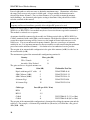
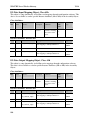
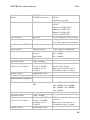
The gains and losses of typical antennas are
Antenna
Gain (dB)
Dipole with integral 15’ cable
0
Weidmuller Part Nos.
WI-ANT-DPL-0-16
5dBi Collinear (3dBd)
5
WI-ANT-COL-5-32
8dBi Collinear (6dBd)
8
WI-ANT-COL-8-54
6 element Yagi
10
WI-ANT-YGI-10-6
16 element Yagi
15
WI-ANT-YGI-15-16
Cable type
RG58
Loss (dB per 30 ft / 10 m)
-5
RG213
-2.5
Cellfoil
Cellfoil
-3
-6
WI-CCSMA-N-33 (33’ or 10m)
WI-CCSMA-N-66 (66’ or 20m)
The net gain of the antenna/cable configuration is determined by adding the antenna gain and the
cable loss. For example, a 6 element Yagi with 66 feet (20 meters) of Cellfoil has a net gain of
4dB (10dB – 6dB).
30
WI-GTWY-9-xxx Wireless Gateway
V1.18
For information on antennas and cables for the WI-GTWY-1 licensed products, please refer to
Weidmuller, Inc. or an authorized distributor.
Connections between the antenna and coaxial cable should be carefully taped to prevent ingress
of moisture. Moisture ingress in the coaxial cable is a common cause for problems with radio
systems, as it greatly increases the radio losses. We recommend that the connection be taped,
firstly with a layer of PVC Tape, then with a vulcanizing tape such as “3M 23 tape”, and finally
with another layer of PVC UV Stabilized insulating tape. The first layer of tape allows the joint
to be easily inspected when trouble shooting as the vulcanizing seal can be easily removed.
Where antennas are mounted on elevated masts, the masts should be effectively earthed to avoid
lightning surges. For high lightning risk areas, surge suppression devices between the module
and the antenna are recommended. If the antenna is not already shielded from lightning strike by
an adjacent earthed structure, a lightning rod should be installed above the antenna to provide
shielding.
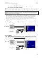
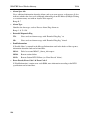
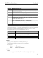
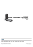
3.2.1
Dipole and Collinear antennas.
1m minimum
for best performance
COLINEAR
ANTENNA
WEATHERPROOF
CONNECTORS WITH
“3M 23” TAPE
SURGE
ARRESTOR
(OPTIONAL)
COAXIAL CABLE
ANT
GND
STRESS RELIEF LOOP
MAST
PROVIDE GOOD
GROUND
CONNECTION TO
MAST, MODULE
AND SURGE
ARRESTOR
INSTALL AERIAL ABOVE
LOCAL OBSTRUCTIONS
EARTH STAKE
IF GROUND CONDITIONS ARE
POOR, INSTALL MORE THAN
ONE STAKE
A collinear antenna transmits the same amount of radio power in all directions - it is easy to
install and use. The dipole antenna with integral 15 ft (5m) cable does not require any additional
coaxial cable, however the other collinear antennas do not have integral cable and an external
cable length must be connected - such as the WI-CCSMA-N-33 or WI-CCSMA-N-66 cable kits..
31
WI-GTWY-9-xxx Wireless Gateway
V1.18
Collinear and dipole antennas should be mounted vertically, preferably no less than 2 ft (0.6
metre) away from a wall or mast to obtain maximum range. The WI-ANT-DPL-0-16 dipole
antenna is the preferred antenna for use in industrial plants and factories.
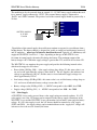
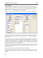
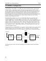
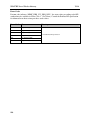
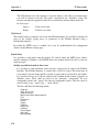
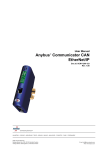
3.2.2 Yagi antennas.
A Yagi antenna provides high gain in the forward direction, but lower gain in other directions.
This may be used to compensate for coaxial cable loss for installations with marginal radio path.
The Yagi gain also acts on the
receiver, so adding Yagi
antennas at both ends of a link
provides a double
improvement.
90o
Yagi antennas are directional.
That is, they have positive gain
Antenna installed
to the front of the antenna, but
with drain holes
down
negative gain in other
directions. Hence Yagi
Coax feed looped
antennas should be installed
at connection
with the central beam
horizontal and must be pointed
exactly in the direction of
transmission to benefit from
the gain of the antenna. The
Yagi antennas may be installed
with the elements in a vertical
plane (vertically polarized) or
in a horizontal plane
(horizontally polarized). For a
two station installation, with
both modules using Yagi
antennas, horizontal
polarization is recommended.
If there are more than two stations transmitting to a common station, then the Yagi antennas
should have vertical polarization, and the common (or “central” station should have a collinear
(non-directional) antenna.
Also note that Yagi antennas normally have a drain hole on the folded element - the drain hole
should be located on the bottom of the installed antenna.
3.3 Power Supply
The WI-GTWY-9-xxx power supply is a switch-mode design which will accept either AC or DC
supply. The module includes an integral battery charger for a backup battery.
The module accepts supply voltages in the following ranges:
32
WI-GTWY-9-xxx Wireless Gateway
V1.18
12 – 24 volts AC RMS or 9 – 30 volts DC at the “supply” terminals, or
10.8 –15 volts DC at the “battery” terminals.
The power supply should be rated at 1.5 Amps and be CSA Certified Class 2. For use in Class 1
Div 2 explosive areas (USA/Canada), the power supply must be approved for Class 1 Div 2 use.
Note: Connect module to the same ground/earth point as the antenna mounting to avoid
differences in earth potential during voltage surges. The modules need an earth connection for
the internal surge protection to be effective.
For licensed 105U units with RF power above 2W, the unit needs to be powered from
the 12V “Battery” terminals with a power supply of at least 2A rating. Alternately, the
unit can be powered via the SUP1 / SUP2 terminals, provided a backup battery is
connected to the “Battery” terminals to supply the inrush current for the radio transmitter.
This is not required for units with radio power less than 2W.
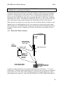
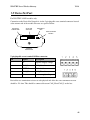
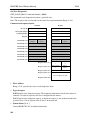
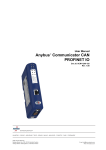
3.3.1 AC Supply
The AC supply is connected to the “SUP1” and “SUP2” terminals as shown below. The AC
supply should be “floating” relative to earth.
Power
Supply
AC Out
12 – 24 VAC
SUP1
SUP2
GND
BAT+
Optional Battery
Fuse 5A
-
+
WI-GTWY
9-xxx
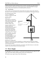
3.3.2 DC Supply
For DC supplies, the positive lead is connected to “SUP1” and the negative to “GND”. The
positive side of the supply must not be connected to earth. The DC supply may be a floating
supply or negatively grounded.
9 – 30 VDC
Power
Supply
DC Out
_
GND
SUP1
+
SUP2
GND
BAT+
Optional Battery
Fuse 5A
-
+
WI-GTWY
9-xxx
33
WI-GTWY-9-xxx Wireless Gateway
V1.18
The module may also be powered from an external 11 – 15 VDC battery supply without the need
for a “normal” supply connected to “SUP1”. This external battery supply is connected to
“BAT+” and “GND” terminals. The positive lead of the external supply should be protected by a
5A fuse
SUP1
SUP2
GND
BATTERY SUPPLY
11-15 VDC
Fuse 5A
BAT+
-
WI-GTWY
+
.Upon failure of the normal supply, the module may continue to operate for several hours from a
backup battery. The battery charger is designed for sealed or vented lead acid batteries between 5
and 24 amphours - other types of batteries should not be used. Typically, a 5 AHr battery will
supply the WI-GTWY-9-xxx for 1 – 2 days, depending on the type of WI-GTWY-9-xxx.
On return of normal supply, the unit will recharge the battery. The maximum output of the
battery charger is 0.7A when the supply voltage is greater than 12V, and 0.3A for less than 12V.
The WI-GTWY-9-xxx monitors the power supply and provides the following internal values,
which can be mapped as I/O values:
•
Power failure (I/O Reg 4309) - if the supply voltage drops below 8V, this status value is set
on, and set off again when the voltage is more than 9V. For AC Supplies, this indicates low
voltage at approximately 10 VAC, and the status is cleared when the supply voltage rises
above approximately 12VAC
•
Low battery voltage (I/O Reg 4308) - this status value is set on if the battery voltage drops to
11.3, and resets off when the battery voltage is more than 11.8V.
•
Battery voltage value (I/O Reg 4310) - 8 – 40VDC corresponds to hex 4000 – hex C000.
•
Supply voltage (I/O Reg 4311) - 8 – 40VDC corresponds to hex 4000 – hex C000.
3.3.3 Solar Supply
A WI-GTWY-9-xxx can be powered from a solar supply using an external regulator. If a 12V
solar supply is used, the 12V battery can be connected to the battery supply connections of the
WI-GTWY-9-xxx and the WI-GTWY-9-xxx will monitor for low battery status and also battery
voltage. If a 24V solar supply is used, the 24V battery should be connected as a DC supply
(SUP1 and GND) - the supply voltage can be monitored however the “supply fail” voltage will
activate too low to be used as a battery fail status.
34
WI-GTWY-9-xxx Wireless Gateway
V1.18
3.4 Input / Output
The WI-GTWY-9-xxx has eight on-board discrete/digital I/O. These act as both discrete inputs
and discrete outputs.
3.4.1 Digital Inputs / Outputs
All eight of the WI-GTWY-9-xxx DIO terminals may be used as discrete inputs. These inputs are
suitable for voltage free contacts (such as mechanical switches) or NPN transistor devices (such
as electronic proximity switches). PNP transistor devices are not suitable. Contact wetting
current of approximately 5mA is provided to maintain reliable operation of driving relays.
Voltage-free
contact input
DIO
DIO
+
_
Transistor
input
GND
V+
V-
WI-GTWY
9-xxx
Each digital input is connected between the appropriate “DIO” terminal and common “COM”.
Each digital input circuit includes a LED indicator which is lit when the digital input is active,
that is, when the input circuit is closed. Provided the resistance of the switching device is less
than 200 ohms, the device will be able to activate the digital input.
+
Max 30VDC
0.5A
_
DC
Load
DIO
DIO
GND
WI-GTWY
9-xxx
All eight of the WI-GTWY-9-xxx DIO terminals may also be used as discrete outputs. The
digital outputs are transistor switched DC signals, FET output to common rated at 30VDC 500
mA.
Digital outputs may be configured to individually turn off if no command message is received to
that output for a certain period. This feature provides an intelligent watch dog for each output, so
that a communications failure at a transmitting site causes the output to revert to a known state.
See Chapter 4 Configuration for further details.
The output circuit is connected to the appropriate “DIO” terminal. Each digital output circuit
includes a LED indicator which is lit when the digital output is active.
35
WI-GTWY-9-xxx Wireless Gateway
V1.18
3.5 Serial Port
3.5.1 RS232 Serial Port
The serial port is a 9 pin DB9 female and provides for connection to a terminal or to a PC for
configuration, field testing and for factory testing. It is also used by the Modbus/DF1 version for
fieldbus connection.
This port is internally shared with the RS485 - ensure that the RS485 is disconnected before
attempting to use the RS232 port. Communication is via standard RS232 signals. The WIGTWY-9-xxx is configured as DCE equipment with the pinout detailed below.
DB9 Connector Pinout:
Pin
Name
Direction
1
DCD
Out
Function
Used for "active" signal.
2
RD
Out
Serial Data Output
3
TD
In
Serial Data Input
4
DTR
In
Data Terminal Ready - may be used by Host Protocol Driver
5
SG
6
DSR
Out
Data Set Ready - always high when unit is powered on.
7
RTS
In
Request to Send - may be used by Host Protocol Driver
8
CTS
Out
Clear to send - may be used by Host Protocol Driver
9
RI
Signal Ground
Ring indicate - not connected
Hardware handshaking using the CTS/RTS lines is provided, and are under the control of the
Host Comms Driver. Example cable drawings for connection to a DTE host (a PC) or another DCE
host are detailed below:
3.5.2
RD
TD
SG
RTS
CTS
DSR
DTR
DCD
36
2
3
5
7
8
6
4
1
2
3
5
7
8
6
4
1
RD
TD
SG
RTS
CTS
DSR
DTR
DCD
MODEM
DCE HOST
DB9
MALE
DB9
FEMALE
RD
TD
SG
RTS
CTS
DSR
DTR
DCD
2
3
5
7
8
6
4
1
2
3
5
7
8
6
4
1
RD
TD
SG
RTS
CTS
DSR
DTR
DCD
MODEM
DCE HOST
DB9
MALE
DB9
MALE
WI-GTWY-9-xxx Wireless Gateway
V1.18
RS485 Serial Port
RS485 should not be used with the DF1 unit. The RS485 port provides for communication
between the WI-GTWY-9-xxx unit and its host device using a multi-drop cable. Up to 32
devices may be connected in each multi-drop network. Note that the RS485 port is shared
internally with the RS232 port - make sure that the RS232 port is disconnected before using the
RS485 port.
WI-GTWY9
INTERNAL
RESISTOR
EXTERNAL RESISTOR
REQUIRED
TERMINATING
RESISTOR SWITCH
ON = TERMINATION
OFF = NO TERM.
RS485 is a balanced, differential standard but it is recommended that shielded, twisted pair cable
be used to interconnect modules to reduce potential RFI. An RS485 network should be wired as
indicated in the diagram below and terminated at each end of the network with a 120-ohm
resistor. On-board 120 ohm resistors are provided and may be engaged by operating the single
DIP switch in the end plate next to the RS485 terminals. The DIP switch should be in the “1” or
“on” position to connect the resistor. If the module is not at one end of the RS485 cable, the
switch should be off.
It is important to maintain the polarity of the two RS485 wires. On the WI-GTWY-9-xxx,
terminal A (the terminal on the right) is positive and terminal B is negative.
37
WI-GTWY-9-xxx Wireless Gateway
V1.18
3.6 Profibus Port
The Profibus RS485 connector is a D9 connector in the top end-plate of the module (see below).
WI-GTWY-9-PR1 (Profibus Slave) End Plate:
PROFIBUS D9
CONNECTOR
RS485
TERMINATION
SWITCH
SELECTOR
SWITCHES
DIAGNOSTIC
LED’s
CONFIGURATION
ENABLE
ANTENNA
CONNECTION
Note: If the “Use Rotary Switch Address” option in configuration software is selected, the two
rotary switches are used to specify the Profibus Node Address in the range 0 – 99. In this case,
the value on the left switch is multiplied by 10 and added to the value on the right switch to give
the node address.
Where the WI-GTWY-9-xxx module is mounted at the end of the RS485 link, the RS485 link
should be terminated by switching the termination switch “on” (down in the above diagram).
WI-GTWY-9-PR2 (Profibus Master) End Plate:
PROFIBUS D9
CONNECTOR
UNUSED D9
CONNECTOR
DIAGNOSTIC
LED’s
CONFIGURATION
ENABLE
ANTENNA
CONNECTION
For the Profibus Master WI-GTWY-9-PR2 a second, unused, connector is also present.
The Profibus RS485 connection should be made to pins 3 and 8 of the Profibus D9 connector.
The pinouts for this connector are:
38
WI-GTWY-9-xxx Wireless Gateway
Pin
Description
1
Not connected
2
Not connected
3
+ve RS485 (Positive)
4
RTS (request to send)
5
GND - Isolated GND from RS485 side
6
+5V - Isolated 5V from RS485 side
7
Not connected
8
-ve RS485 (Negative)
9
Not connected
V1.18
3.7 Ethernet Port
For WI-GTWY-9-ET1 modules only.
The Ethernet connection uses a standard RJ45 connector on the top end-plate of the module. The
selector switches should all be “off” (in the diagram below, “off” is up).
RJ45 ETHERNET
CONNECTION
SELECTOR
SWITCHES
DIAGNOSTIC
LED’s
CONFIGURATION
ENABLE
ANTENNA
CONNECTION
39
WI-GTWY-9-xxx Wireless Gateway
V1.18
3.8 Modbus Plus Port
For WI-GTWY-9-M+1 modules only.
Connection to the Modbus Plus Network is via the 9-pin D-SUB connector located at the antenna
end of the module. Pin-outs are outlined in the table below.
D9 MODBUS
PLUS
CONNECTION
SELECTOR
SWITCHES
DIAGNOSTIC
LED’s
CONFIGURATION
ENABLE
ANTENNA
CONNECTION
See section on configuration for description of selector switches.
Modbus Plus 9-pin D-SUB Connector:
Pin
Name
1
Cable Shielding
2
MBP Line B
3
MBP Line A
Housing
PE
40
WI-GTWY-9-xxx Wireless Gateway
V1.18
3.9 DeviceNet Port
For WI-GTWY-9-DE1 modules only.
Connection to the DeviceNet Network is via the 5-pin plugable screw terminal connector located
at the antenna end of the module. Pin-outs are specified below.
DEVICENET
CONNECTION
SELECTOR
SWITCHES
DIAGNOSTIC
LED’s
CONFIGURATION
ENABLE
ANTENNA
CONNECTION
5-pin plugable screw terminal fieldbus connector:
Pin
Signal
Description
1
V-
Negative Supply Voltage
2
CAN_L
CAN_L bus line
3
SHIELD
Cable shield
4
CAN_H
CAN_H bus line
5
V+
Positive supply voltage
DeviceNet uses termination resistors at each physical end of the bus. The termination resistor
should be 121 ohm. This should be connected between CAN_H and CAN_L on the bus.
41
WI-GTWY-9-xxx Wireless Gateway
Chapter 4
V1.18
CONFIGURATION
4.1 Introduction
A Windows program is provided to configure the WI-I/O 9-x system. The configuration is done
on a system basis - referred to as a “project” in the program. After the system configuration is
entered, the configuration file can be loaded into each module via the RS232 port.
Each Project is configured with:
•
a system address, which is common to every module in the same system, and is used to
prevent "cross-talk" between modules in different systems. Separate networks with different
system addresses may operate independently in the same area without affecting each other.
The system address may be any number between 1 and 32 767. The actual value of the
system address is not important, provided all modules in the same system have the same
system address value. A system address of zero should not be used. The configuration
program automatically offers a random number for the system address - you can change this
to any number in the valid range but we recommend that you use the random number.
•
a password for access protection. This is an optional feature. If selected, the project file can
only be opened by entering the correct password.
•
a security encryption key, used to encrypt and decrypt radio messages. This is an optional
feature. If selected, the configuration program will offer a random security key, or this can
be over-written with your own key. A key is a string of any 8 ASCII characters.
Each module in the project is configured with a unit address. Each module must have a unique
unit address within the one system. A valid unit address for a WI-GTWY-9-xxx is 1 to 95. A
network may have up to 95 addresses communicating directly via radio (unit addresses 1 to 95).
WI-I/O 9-x I/O modules can have up to 31 modules communicating via RS485 (unit addresses 96
to 127).
The configuration program may allocate more than one unit address to a WI-GTWY-9-xxx if it is
required because of the size of the system. If this is necessary, it will be done automatically by
the configuration software.
Configuration consists of:
1. selecting the types of modules in the system and selecting address values
2. linking (called “mapping”) I/O registers to remote I/O
3. setting operating parameters such as change sensitivities and update times
4. selecting “block mappings” - only for block transfer of I/O registers between WI-GTWY-9xxx modules
5. selecting fieldbus addressing, and serial port configuration (Modbus & DF1 only)
6. linking Radio Interface registers to Fieldbus Interface registers (All modules except MD1)
42
WI-GTWY-9-xxx Wireless Gateway
V1.18
All of these steps must be performed to configure the WI-GTWY-9-xxx module.
4.2 Configuration Program
The configuration software is available on a CD, and needs to be installed on your PC before you
can use it. The CD contains a setup file called setup.exe. Select the configuration software
window on the Product CD and an installation Wizard will guide you through the installation
procedure. To upload and download configuration files to a module, you will need a RS-232
serial cable as shown below.
WI-GTWY-9-xxx
DB9 Male
1
2
3
4
5
6
7
8
9
PC
DB9 Female
1
2
3
4
5
6
7
8
9
Required
Optional
43
WI-GTWY-9-xxx Wireless Gateway
V1.18
4.2.1 Program Operation
Start the software by either clicking on the start bar and navigating to the Configuration menu or
by running WI SERIES.EXE in the directory selected in the setup stage.
The Initial screen will appear.
From the initial screen, , you can
select an existing project, or start
a new project. The name of the
project will create a new folder
which will eventually contain the
configuration files for the
modules in this system. Project
folders are located under the
folder \Projects\ - for example,
if you create a project called
“Fire Pumps”, then the files for
this project will be found in the
folder c:\……\Projects\Fire Pumps\.
When you have selected the project, a screen will appear
where you may enter the system address.
If you are editing an existing project, the system address
will already have been entered. Do not change the system
address unless you are going to re-program all of the
modules in the system.
Password. You have the option of entering a password to
protect the configuration files against unauthorized
changes. When you open a new project, you will be asked
to enter a password - if you do not enter any text - that
is, press “ESC” or “Enter”, then password protection is
disabled. If you do enter a password, then you will need to
enter this password to access the project. Without the
password, you are unable access the project
The password can be between 6 and 256 characters. You
44
WI-GTWY-9-xxx Wireless Gateway
V1.18
can also change password at any time by over-typing the passowrd.
If you are starting a new project, you have the option of “Enabling Security”. This option enables
encryption of the data
sent over the radio. please read Section
4.2.2 and the
associated warnings
before using this
option.
To proceed with the
configuration, doubleclick on the project
name on the menu on
the left side of the
screen. “Units” will
appear. You can now
enter the types of units
which will be used in
the system. If you double-click on “Units”or select the “+” sign beside “Units”, then the modules
that have already been created will be displayed.
Loading configuration from an existing module
To load the configuration from a module, connect the module to the PC via the RS232 cable, put
the module into “Configuration Mode” by pressing the configuration button on the top end-plate,
and click on “Load Unit”. This will allow you to view the module configuration, change it, or
copy it for another module - refer to section 4.3 for full
details.
Adding a new module to the system configuration
To add a new module to the system configuration, click
“Units” on the left-hand menu and then “Add Unit”.
Select the type of module from the list. For WI-GTWYxxx modules, you will be asked to select the bus
protocol. This must match the WI-GTWY-9-xxx module
type you have installed.
You have the option of selecting a unit address for the
module, or allowing the program to select one
automatically. If you choose to select the unit address the
program will display the list of available addresses for
to select - valid addresses are 1 – 95.
on
9-
you
45
WI-GTWY-9-xxx Wireless Gateway
V1.18
The default name for a unit will include the unit address. For example, “WI-GTWY#10” is a
WI-GTWY-9-xxx module with unit address 10. You can change the name of a unit - for
example, you could replace the default name with “Pump Station 14”.
46
WI-GTWY-9-xxx Wireless Gateway
V1.18
Deleting a Unit
A module can be deleted from the configuration by highlighting the unit and selecting “Delete
Unit”.
4.2.2 Security
There are two security features available. You can enter a password to protect the configuration
files, and you can enable security encryption of the radio transmissions.
The password can be between 6 and 256 characters. The password is case sensitive and any
ASCII characters can be used. If you have entered a password, then this password will need to be
entered whenever the configuration is changed. You are able to change the password from the
“Utilities” menu. If unauthorized access to the files is a concern, we recommend that you change
the password regularly or whenever there is a change of staff.
Data Encryption is an additional level of security. The security option uses a 64 bit security key
to provide data encryption of the radio messages. All modules in the same system will be
configured with the same security key used to encrypt and decrypt the messages. This feature is
available for modules with firmware version 2.1 and higher. If you are adding modules to an old
system which does not have the security encryption feature, then you cannot use security
encryption on the new modules.
Note that the security key is different than the password.
•
To enable the security encryption, select the “Enable Security” box on the project display.
An 8-character random security key is automatically generated. If desired, a different security
key may be entered and you will be prompted to enter the security code a second time to
confirm. The security key can be any characters or numbers. Characters are case sensitive.
The security key will never be displayed.
47
WI-GTWY-9-xxx Wireless Gateway
V1.18
•
If you do not enable security, there will be no data encryption of the radio messages. This is
the default setting.
•
If a security key has been entered, this key is downloaded into each module as part of the
configuration download process. You can download another configuration at any time - if
the security key is different, or if there is no security key in the new configuration, the old key
will be over-written.
•
You can change the security key in the configuration files simply by entering a new security
key in the security key window. You will be prompted to confirm the new security key.
Note that if you change the security key, it will not match the security key previously loaded
into existing modules.
•
If you want to change a configuration, we recommend that you change the archived
configuration, and then download the configuration onto the module. The archived
configuration already has the valid security key.
•
If you lose the archived configuration, you can upload the configuration from a module, but
you cannot upload a security key. That is, you can upload the module configuration, view it,
change it - but if you don’t know the original security key, the old key will be over-written
when you download the new configuration. This module will no longer communicate with
other modules in the system as the security key is different.
Warning!!
These security options provide a high level of security, but no data-security system can
provide “100% protection”. But it does make it very difficult for someone to interfere
with the WI-I/O 9-x system - difficult to the point where there would be many easier
alternate ways to cause malicious damage.
The password must be kept in a secure place. Security procedures need to be adopted. If
staff with access to the password leave your organization, we recommend that the password
be changed.
We recommend that you use a random 8-character string for the security key and that you
do not record the key. It is not necessary to know what the security key is. The key will be
recorded in the archived configuration files, and therefore the configuration files should be
held in a secure place and backed up.
The security key does not prevent a hacker uploading a configuration from a module and
downloading with a new security key. This module will no longer operate with other
modules in the system. To prevent this, unauthorized access to modules must be prevented.
The security options provide security against a “hacker” in the following way:
A hacker cannot listen-in to radio messages without the security key to decrypt the radio
messages. Similarly, a hacker cannot force outputs by transmitting a radio message to a
module without the security key.
A hacker cannot access the security key from an installed module or from the configuration
files.
48
WI-GTWY-9-xxx Wireless Gateway
V1.18
The archived configuration files cannot be changed, downloaded or uploaded without the
password.
If you lose the configuration files, you can regenerate these by uploading the configuration from
every module in the system into a new project with a new security key. After uploading each
module, download the configuration with the new security key.
If you wish to change the security key, simply enter a new key in the configuration program, and
download the new configuration to all modules in the system.
Note on Ethernet WI-GTWY-9-xxx. You are able to access the module configuration of an
Ethernet WI-GTWY-9-xxx via the Ethernet port. To prevent this access, do not select “Enable
Ethernet Debug” on the Ethernet configuration display - see section 4.8.
4.3 Uploading and Downloading
To upload or download a configuration file, the WI-GTWY-9-xxx must be connected to the PC
via a RS232 cable. For Modbus/DF1 units, the host device must be disconnected, even if it is
connected to the RS485 port. Other units do not need to disconnect the data bus. When the PC
is connected, put the WI-GTWY-9-xxx into configuration mode by pressing the small
pushbutton switch in the end plate of the module for 5 seconds, until the ACT LED starts
flashing.
In configuration mode, the WI-GTWY-9-xxx will stop its normal functions.
Make sure the correct
communications port is
CONFIGURATION
ENABLE
selected on the PC - if
necessary, change the
ANTENNA
CONNECTION
selection from the
Utilities menu.
Connect the PC to the
module using the
configuration cable.
WI-I/O 9
PC End
End DB9
The configuration may
DB9 Female
Male
be programmed into a
1
1
WI-GTWY-9-xxx, or a
2
configuration may be
2
3
loaded from a WIRequired
3
4
GTWY-9-xxx. After
4
5
programming or
5
6
loading is complete,
Optional
6
disconnect the PC from
7
7
the WI-GTWY-9-xxx.
8
Reset the WI-GTWY8
9
9-xxx by removing
power and re-connecting power. The WI-GTWY-9-xxx will start up normally and the OK LED
will be on. The serial port will have its original set-up.
49
WI-GTWY-9-xxx Wireless Gateway
4.3.1
V1.18
Loading from a WI-GTWY-9-xxx
If you load a configuration from a WI-GTWY-9-xxx into a “blank” or new project, then the
program will not be able to display the mappings from remote modules (as the program does not
know what the remote modules are). You will get a warning message like this:
If you open the archived project first, and load into the archived project, then all mappings will
display as normal - any mappings to/from the WI-GTWY-9-xxx will be over-written on the PC
display by the loading process.
If you are unable to load into the archived project, then mappings to remote modules will be
displayed, but mappings from remote inputs will be shown as “Unknown Mappings”.
If you also load the configurations from the other remote modules in the system, then these
unknown mappings will disappear as the program can determine where the remote inputs are.
Alternately, you can select “Link Mapping” and manually enter the remote inputs.
50
WI-GTWY-9-xxx Wireless Gateway
V1.18
4.4 Mappings WI-GTWY-9-xxx to
WI-I/O 9-x I/O Modules
To transfer remote input signals to a WI-GTWY-9-xxx, or
transfer a value to a remote output from a WI-GTWY-9xxx, you set up “I/O mappings”. You enter mappings into
the source unit, not the destination unit. That is, you
configure a mapping at the “input” module. If you want to
transfer an input signal at a WI-I/O 9-x module to a WIGTWY-9-xxx register, you enter a mapping at the WI-I/O 9x I/O module. If you want to transfer a WI-GTWY-9-xxx
register to an output signal at a WI-I/O 9-x module, you
enter a mapping at the WI-GTWY-9-xxx module.
To configure mappings, double-click on the module in the left-hand menu - the menu will
expand with selections for that module. Select “Mappings”.
Each mapping comprises only one I/O point. “Block Mappings” provide more advanced
communications between WI-GTWY-9-xxx modules.
4.4.1 Mappings from Inputs at Remote WI-I/O 9-x I/O Modules
Refer to the WI-I/O 9-x I/O User Manual.
When mapping inputs to a WI-GTWY-9-xxx, you will be asked to select an I/O Register. Select
the “…” box beside the “At I/O Register” heading - this will allow you to select the I/O register
between 0 and 4299. Any I/O registers that have already been selected will have a color shading.
The update times, analog sensitivities for these mappings can be set as per normal I/O mappings.
To map several inputs to consecutive I/O registers, use “Shift”-select or “Ctrl” - select to
highlight the inputs, and select the first I/O register in the range. The selected mappings will be
entered with consecutive I/O registers.
51
WI-GTWY-9-xxx Wireless Gateway
V1.18
For each “remote input” configured to a WI-GTWY-9-xxx, there is a comms-fail time parameter
in the WI-GTWY-9-xxx. If the WI-GTWY-9-xxx does not receive a message destined to that
I/O register within the “comms fail” time, then the “comms fail” status for that I/O register will
be set - the most significant bit of the status register will be set to 1. The comms fail time
should be more than the corresponding update time at the remote input.
To set the comms fail times, select the WI-GTWY-9-xxx, and select the “Comms Fail Time”
option. Each remote input already mapped to the WI-GTWY-9-xxx will automatically be listed,
including the remote module containing the mapping.
The default value for the
comms-fail time is “disabled”
or zero. To enter a time,
select the I/O register from the
list. The comms-fail time
should be greater than the
update time of the remote
input.
Firmware version 1.76 and later:
The I/O value in the I/O registers can be reset to zero on comms-fail. To enable this, select the
enable box in the “Comms Fail Times” configuration screen. Note that this is a global selection;
comms-fail-reset is configured on all registers or no registers.
4.4.2 Mappings from WI-GTWY-9-xxx to Outputs at Remote WI-I/O 9-x I/O Modules
Mappings can be entered in the WI-GTWY-9-xxx to remote outputs. Select the “Mappings”
option under the WI-GTWY-9-xxx. Select an I/O register and select the remote module and the
output channel.
To map several consecutive I/O registers to several outputs, select the first I/O register in the
range and use “Shift”-select or “Ctrl” - select to highlight the multiple outputs. The selected
mappings will be entered with consecutive I/O registers.
52
WI-GTWY-9-xxx Wireless Gateway
V1.18
Change Sensitivities
Radio messages to remote modules can be change messages (when the value of the I/O register
changes) or update messages (when the update time has elapsed). If a change message is sent,
the update period restarts.
You can configure the amount of change required to trigger a change message - this is called the
change sensitivity. Sensitivities are configured for blocks of I/O registers - that is, each I/O
register does not have a unique sensitivity. You can configure up to 50 sensitivity values - that
is, there can be 50 blocks of registers with different sensitivities.
For more information on this, refer to section 4.6.
53
WI-GTWY-9-xxx Wireless Gateway
V1.18
Update Times
To change the update times of
output mappings, select the
Update Times option. Any
I/O registers that have already
been mapped to remote
outputs will automatically be
listed. The default update
time is 10 minutes.
Changing Multiple Settings
You can change the Comms
Fail Times or Update Times of several I/O points simultaneously by using the <Shift> Select
feature. For example, if you want to change all times to 1 minute, you could change each
individually, or you could “block” all entries using the “Shift” Select feature and select “Edit”.
You only need to enter the change once to change all of the inputs selected. This feature is also
available with the other configurable parameters.
4.4.3 Don’t Send if in Comm Fail
You can configure a special “Don’t Send if in Comms Fail” mapping. If this is configured for a
particular remote module, the WI-GTWY-9-xxx will not transmit output messages to this remote
address, if there is a communications failure status on any input or output configured for the
same remote address. Output messages will re-start when a message is received from the remote
module. The use of this option can prevent the radio channel becoming congested if there are
many outputs at that module.
To configure this special mapping, select the “New Don’t Send in Comms Fail Mapping” box.
You will be asked to select which remote module this function applies to. You can enter more
than one of these mappings if there are more than one modules.
54
WI-GTWY-9-xxx Wireless Gateway
V1.18
4.4.4 Startup Polls
You can enter start up polls for remote modules by using the “New Poll Mapping” box. This
function is the same as for the WI-I/O 9-x I/O modules. A start-up poll is a special message sent
when the WI-GTWY-9-xxx starts up. When the remote module receives a start-up poll, it will
immediately respond with update messages for all its inputs that are mapped to the WI-GTWY-9xxx. This allows the WI-GTWY-9-xxx to have correct values on start-up.
4.4.5 Polls to Remote Modules
It is possible for a WI-GTWY-9-xxx to send a poll to a remote module at other times apart from
start-up. A poll can be sent under the following events:
•
based on a configurable time period
•
based on real time clock
•
on-demand by the host device.
For information on this configuration, refer to the next section on “Block Mappings”.
4.5 Mappings from WI-GTWY-9-xxx to other WI-GTWY-9xxx Modules
Individual links between WI-GTWY-9-xxx modules can be configured under the “Mappings”
selection as described in the previous section. For example, if you want to transfer I/O Reg 144
in WI-GTWY-9-xxx#2 to I/O Reg 286 in WI-GTWY-9-xxx#3, you can enter the following
mapping:
Whenever I/O Reg 144 changed by the sensitivity amount, WI-GTWY-9-xxx#2 would send a
message to WI-GTWY-9-xxx#3 to write the value in I/O Reg 286. The problem arises if there
are a lot of these mappings. Each radio message only relates to one register-register link. If you
want to map 1000 registers from one WI-GTWY-9-xxx to another, then this could generate a lot
of radio messages.
55
WI-GTWY-9-xxx Wireless Gateway
V1.18
To get around this problem, it is possible to configure “block mappings”. With a block mapping,
multiple registers (a “block of registers”) can be transferred together in the one radio message.
This improves the efficiency of the radio communications.
Read/Write Mappings
The mappings can be “read” or “write” mappings. A Read mapping is a request sent to another
WI-GTWY-9-xxx to return a block of values. A Write mapping is a message sending a block of
values to another WI-GTWY-9-xxx. A Read mapping from WI-GTWY-9-xxx#2 to WI-GTWY9-xxx#3 could be the same as a Write mapping from WI-GTWY-9-xxx#3 to WI-GTWY-9xxx#2 (that is, in the reverse direction) - except the Read mapping is initiated from #2 and the
Write mapping is initiated from #3.
BLOCK OF I/O
REGISTERS
BLOCK WRITE
MESSAGE
ACKNOWLEDGMENT
LOCAL
WIGTWY9-xxx
READ REQUEST
REMOTE
WIGTWY-9xxx
BLOCK READ
MESSAGE
BLOCK OF I/O
REGISTERS
Word/Bit Mappings
Read and Write mappings are also selected as Word or Bit mappings - that is, you can select a
Read Word mapping or a Read Bit mapping and you can select a Write Word mapping or a Write
Bit mapping. “Word” refers to a complete 16-bit register value; “Bit” refers to the value of the
most significant bit of a register - this bit is the “binary value” or “digital value” of the register.
If you use a Word block mapping of 50 registers, you are transferring a block of 50 x 16-bit
values. If you use a Bit block mapping of 50 registers, you are only transferring the digital value
of each register - that is 50 x 1 bit values. This is a lot more efficient for a radio message, but
bit mappings are only suitable for discrete or digital I/O. A Bit mapping will convert the 16-bit
register to a single bit, transfer it and store the bit value in the most significant bit of the
destination register.
Note: The maximum block size for each block mapping is 64 registers.
56
WI-GTWY-9-xxx Wireless Gateway
4.5.1
V1.18
Entering a Block Mapping
Select the “source” WI-GTWY-9-xxx on the left hand menu - select “Block Mappings” and
then “New Block Mapping” from the right-hand display. The Block Mapping Configuration
display will appear.
Select the “Command Type” from the pop-down window in the centre of the display. The red
arrow will confirm the direction of the block transfer. Now select the destination module - only
the WI-GTWY-9-xxx modules already configured will be shown. If you need to use repeaters in
the radio link, enter the repeater addresses, starting with the repeater closest to the source
module.
Under “Source Gateway”, enter the I/O Register and I/O Count. The I/O Register is the first
register in the block and the I/O Count is the number of registers - in the above example, the
block of registers will be 110 – 124 (15 registers starting at I/O Reg 110).
If you are entering a Write mapping, then the values in this block will be sent to another WIGTWY-9-xxx. If it is a Read mapping, then values from another WI-GTWY-9-xxx will be sent
to this block.
Under “Destination Gateway”, enter the I/O Register - this is the first register in the block. You
do not need to enter the block size as this will always be the same as the block size in the source
WI-GTWY-9-xxx. In the above example, the destination block will be I/O registers 32 – 46 (15
registers starting at register 32). So, in the above example, a block of 15 x 16-bit values will be
written from I/O Reg 110 – 124 in WI-GTWY-9-xxx#1 to I/O Reg 32 – 46 in WI-GTWY-9xxx#2.
57
WI-GTWY-9-xxx Wireless Gateway
V1.18
Each mapping entered is allocated a status register - the register number appears on the right
hand of the Block Mapping display. These registers store relevant status information about the
block mapping - the structure of the Block Mapping status registers is shown in Appendix 1.
In the above example, the status register for the block mapping has been automatically assigned
to register 9500.
The rest of the mapping configuration involves the mapping trigger - or what initiates the
mapping message.
Firmware version 1.82 and later.
Block write mappings have option to invert the I/O message that will be sent. This can be
selected when adding new write block mapping
Mapping “Triggers”
A block mapping can be “triggered” or initiated by several different methods.
•
By the host device writing to a “trigger register” in the source WI-GTWY-9-xxx - the block
mapping message is sent each time the host device writes to the trigger register.
•
By configuring a time period - the WI-GTWY-9-xxx will send the block mapping message
if this time period has elapsed since the last message has been sent.
•
By configuring a real-time clock - the WI-GTWY-9-xxx will send the block mapping
message at the configured times.
•
By a change-of-state within the I/O block. This can only occur for Write mappings. If a
value in the block changes by more than the sensitivity amount, then the block message will
be sent. You can enter a delay period such that the message is sent after the delay period.
Combinations of the above triggers can occur - for example, the block mapping message will be
sent if a change-of-state occurs, AND at the configured real-time, AND when the host device
writes to the trigger register.
4.5.2
58
Host Device Trigger
WI-GTWY-9-xxx Wireless Gateway
V1.18
Each block mapping that is configured is allocated a status register in the range 9500 – 9999 (i.e.
one status register for a maximum of 500 possible block mappings). The status register for a
given block mapping is shown on the right hand side of the Block Mapping display (under the
heading “Status Lcn”). Bit 13 of the associated status register is the “Force bit” - if Bit 13 is
turned “on”, then the associated mapping is forced, or triggered. Depending on the module
version, a particular algorithm may apply to the setting of the force bit. This algorithm and details
of the block status registers are given in Appendix 1.
4.5.3 Time Period
On the Block Mapping display, there are two configuration windows - “Period” and “Offset” these determine the time period trigger and real-time trigger.
For a time-period trigger, select “Continuous” in the “Period” pop-down window. Under
“Offset” enter the time-period in seconds. In the above example, the mapping will be sent every
300 seconds or 5 minutes.
Note that the time period is after the last transmission - if the block mapping message is triggered
by the host device, or by a change-of-state, then the timer is reset and the time period starts again.
The “Offset” value can be set from 0 – 4095 seconds (68 minutes). If you do not want the
message to be sent on a time period, set the “Offset” value to zero.
If you want the block mapping to be sent only on time period (and not on change as well), select
the “Disable” box in the bottom left hand corner - this disables change messages for this block
mapping. If you want any changes sent within this Time period uncheck Disable box and enter
in time to wait before sending only the I/O that has changed in the Block.
59
WI-GTWY-9-xxx Wireless Gateway
V1.18
4.5.4 Real-Time
The block mapping message can be sent at a real-time by setting the “Period” value. In this
example, “period” is set to 6 minutes - the message will be sent every 6 minutes starting at the
beginning of each hour. That is, the message will be sent at XX:00, XX:06, XX:12, XX:18,
XX:24 …. XX:54 - where XX represents any hour of the day.
If “Period” was set to 1 minute, then the message would be sent every minute, on the minute.
The “Offset” value provides an offset to the specified time. In this example, if the “Offset” was
set to 10 seconds, then the messages will be sent 10 seconds later - at XX:00:10, XX:06:10,
XX:12:10 etc.
The reason for the offset is to stagger messages with the same time setting. For example, if you
configure 5 block mappings all to be sent at 10 minutes, then the WI-GTWY-9-xxx will try to
send these messages at the same time - some of the messages will have to wait until the earlier
messages have been sent. If you are sending Read messages as well as Write messages, then the
return messages could clash with outgoing messages.
To avoid this, you can delay some messages using the Offset feature. For example, if you have 5
mappings to be sent at 10 minutes, then the first could have zero offset, the second 3 sec offset,
the third 6 sec offset etc.
If you do not wish to have a real-time trigger, set “Period” to continuous.
If you want the block mapping to be sent only on real-time (and not on change as well), select
the “Disable” box in the bottom left hand corner - this disables change messages for this block
mapping.
60
WI-GTWY-9-xxx Wireless Gateway
V1.18
Setting the Clock
The clock within the WI-GTWY-9-xxx can be set by the host device, and read by the host
device. The WI-GTWY-9-xxx provides four clock registers for days/hours/minutes/seconds - the
registers are 4330 – 4333. On power-up, these registers are set to zero. Reg 4333 increments
each second, Reg 4332 increments each minute, Reg 4331 each hour and Reg 4330 each day.
The clock registers are used by the WI-GTWY-9-xxx for the real-time-clock trigger. The host
device can read these registers. The host device can also set the WI-GTWY-9-xxx clock at any
time by writing to the appropriate Set register. The Set registers are : 4340 – 4343. The procedure
for setting the real time clock via these registers depends on the module firmware version (to find
out what firmware version the module contains, simply display the diagnostics menu – see
section on diagnostics). The set registers can also be set via radio using appropriate I/O or block
mappings.
Item
Clock Location
Set Location
Days
4330
4340
Hours
4331
4341
Minutes
4332
4342
Seconds
4333
4343
Firmware versions up to 1.50:
Registers 4340 – 4343 are normally zero. When a value is written into one of these registers, the
WI-GTWY-9-xxx copies the value into the corresponding clock register, and then sets the Set
register back to zero. For example, if the host device writes a value of 7 into Reg 4341, the WIGTWY-9-xxx will write 7 into 4331 and set 4341 back to zero.
Firmware version 1.50 and later:
Registers 4340 – 4343 will only be transferred to the corresponding clock registers when their
value changes from 0. For example to write a value of 7 to the hours register, first write the value
0 to the Set hours register 4341, then write the value 7 to the same register. (i.e. by always first
writing the value 0 to the Set register this ensures that the change-of-state from 0 will be
detected). Values must be held (i.e. not change) for approx 200msec to be detected.
61
WI-GTWY-9-xxx Wireless Gateway
4.5.5
V1.18
Change-of-State
If a value in the block changes by more than the sensitivity amount, then the block message will
be sent (this can only occur for Write mappings). The sensitivity values are set under the
“Sensitivity” option as per section 4.6.
A delay time can be entered to reduce the number of change triggers in active systems. For
example, if 20 seconds is selected in the “Delay” window, then the change message will be sent
20 seconds after the change-of-state occurs - if other changes occur during the 20 second period,
all of these changes are sent in the one message.
The delay time can be set from 0 – 254 seconds.
If you do not wish change messages to occur, select the “Disable” box.
4.5.6 Block Read Mappings
A Read mapping is a request sent to another WI-GTWY-9 to return a block of values. Like the
Block Write mapping it can be triggered by a Real Time clock, Time period or by Host trigger
however the main difference is that the COS Delay is now a Response Timeout as shown below.
62
WI-GTWY-9-xxx Wireless Gateway
V1.18
In the above example WI-GTWY-9#1 is performing a Block Read Request to WI-GTWY-9#2.
WI-GTWY-9#1 will send a block mapping request to WI-GTWY-9#2 who will then send a
block mapping from its I/O registers 52 for a count of 10 to WI-GTWY-9#2 I/O registers 52 –
61. This Block read will be performed using the real time clock at 10-minute intervals. A
response timeout of 5 seconds is used to indicate that if the Block read values have not been
received in 5 seconds then the Comms Fail bit for this block read mapping will be set.
It is not recommended to have the Response Timeout set to 0 seconds as a Comms fail bit will be
set upon transmission.
If the Response Timeout is greater than the Block mapping time period and radio’s are in a High
traffic or poor radio path then instances could occur that received messages could be from
previous block read mapping’s hence giving incorrect values.
If a need for frequent communications between modules is required then Block Write mapping’s
would be more suitable.
4.5.7 Mixing Normal Mappings and Block Mappings
Block mappings can include I/O Registers already used with normal I/O mappings.
For example, a remote WI-I/O 9-x I/O module could map a remote input to I/O Reg 743. At the
WI-GTWY-9-xxx, the host device could read I/O Reg 743, and you could also configure a block
mapping including this register to another WI-GTWY-9-xxx. You could write a block I/O Reg
700 – 800 to another WI-GTWY-9-xxx.
4.5.8 Block mapping to Internal I/O registers
Firmware version 1.80 and later:
63
WI-GTWY-9-xxx Wireless Gateway
V1.18
The Block mapping feature will allow a Write Block Mapping to itself. This could be useful if
you have a global output to indicate a comms problem from any remote module by block
mapping the internal status registers to a local DIO output.
4.5.9 Comms Fail for Block Mappings
Each block mapping has an associated mapping number. Up to 500 block mappings may be
entered. A status register is maintained for each block mapping. The most significant bit of this
register contains the comm fail status.
If a block mapping does not receive an acknowledgement from the remote module, then the
comms fail status is set - this can be monitored by the host device.
4.5.10 “Repeater-only” Configuration
Any WI-GTWY-9-xxx module can act as a repeater unit. However a WI-GTWY-9-xxx may
need to be installed as a repeater only (that is, there is no host device connected). In this case,
the base WI-GTWY-9-xxx, the WI-GTWY-9-xxx-MD1 unit would normally be used as this is
the lowest cost of the WI-GTWY-9-xxx modules.
A repeater can be configured as a “Repeater-only” unit. The advantages are:
the serial port will then provide on-line diagnostics (instead of off-line diagnostics), or
WI-I/O-EX-1-S-1x serial I/O modules can be connected to the serial port - normally an
MD1 could not be used as the serial ports would already be in use by the protocol device, eg
PLC, etc.
64
WI-GTWY-9-xxx Wireless Gateway
V1.18
4.6 Change Sensitivity & I/O Value Scaling
4.6.1 Change Sensitivity
“Change” messages for both individual I/O mappings and block mappings use a sensitivity value
to trigger the message. Sensitivities are configured for blocks of I/O registers - that is, each I/O
register does not have a unique sensitivity. You can configure up to 50 sensitivity values - that
is, there can be 50 blocks of registers with different sensitivities.
Enable scaling
In the above example, three sensitivity blocks have been configured:
1. I/O registers 0 – 49 have a sensitivity of 1000 (or 1.5% of the 16 bit range)
2. I/O registers 100 – 499 have a sensitivity of 250 (or 0.4% of the 16 bit range)
3. I/O registers 1000 – 2999 have a sensitivity of 100 (or 0.15% of the 16 bit range)
All of the registers between 0 and 49 have a sensitivity value of 1000. If register 34 has changed
value by more than 1000 since the last transmission for that register, then a change trigger will
occur for register 34. Sensitivity values are in decimal and can vary between 1 and 65535 (16bit).
Up to 50 blocks of sensitivities can be configured. If a register is included in more than one
block, then the first sensitivity value configured will be accepted and later values ignored. If
Scaling is configured (refer next section), then the number of blocks is reduced to 25.
Registers which are not included in any block use the “default” sensitivity which is also userconfigurable. In the above example, the default sensitivity is 1 and is the sensitivity for all I/O
registers not included in the three blocks.
Important Note. Sensitivity values need to be selected carefully for analogue or counting
registers as small values can result in a large number of change messages, which can overload the
65
WI-GTWY-9-xxx Wireless Gateway
V1.18
radio channel. A sensitivity value of 1 in 65535 is a change of 0.0015%. If the host device
writes an analogue value to a WI-GTWY-9-xxx every 100msec, it will change by at least 1 bit
each time. A small sensitivity value will cause a change message to be sent every 100msec. If
there are many analogue values in the same situation, then there would be many change
messages every 100msec. Sensitivity values for analogue I/O should be set to be greater than the
normal process noise of the signal. For example, if a flow signal has a normal process
oscillation of 2.5%, then the sensitivity should be set to 3% (or a value of 2000) to avoid change
transmissions from the process oscillations.
4.6.2
I/O Value Scaling
Firmware version 1.76 and later:
The values in I/O registers can be scaled as the values are transferred to the data bus, or from the
data bus.
The I/O values in the WI-GTWY-9-xxx database registers are stored as 16-bit values (between 0
and FFFF hexidecimal or 0 and 65,535 decimal). Analog inputs at a WI-I/O 9-x I/O module are
scaled hex 4000 (dec 16,384) for 4mA and hex C000 (dec 49152) for 20mA. A 12 mA signal is
half-way in this range at hex 8000 (dec 32,768).
The reason for adding additional scaling between the WI-GTWY-9-xxx database (radio side) and
the data bus is to cater for external host devices which do not handle normal 16-bit values. Two
examples are:
Honeywell Modbus gateways which only handle 12-bits values (0-4,095 decimal), and
Sensor / analyzer devices with “signed 16-bit” values. A signed 16-bit value is a 15-bit value
with an additional bit to signify plus (0) or minus (1).
Scaling of I/O registers can be configured in blocks. Different blocks can have different scaling.
Note that scaling only affects values transferred in or out of the data bus port. It has no affect on
the radio side.
66
WI-GTWY-9-xxx Wireless Gateway
V1.18
Scaling is configured in the “Sensitivities” section of the configuration software. If you select a
new sensitivity/scaling block, you can select/deselect sensitivity or scaling or both. There is no
relationship between sensitivity and scaling we use the same configuration area as it is
convenient because both features use blocks of
I/O registers.
In the first example, a block of I/O registers is
configured for both sensitivity and scaling. I/O
block 0 to 79 (total of 80 registers) is
configured with a sensitivity value of 500. The
same block has scaling configured converting
the range 16384-49152 on the radio side to 04095 on the data bus side.
If both
Sensitivity
and Scaling is
required,
either function
can be
This is an example of converting a 4-20mA
value to a “Honeywell 12-bit value”. Note that
the scaling works in both directions - for
values being read from the I/O registers to the
data bus, and values written from the data bus
to the I/O registers.
Any values outside of the scaling range are set
to the minimum or maximum value. For
example, if the data bus read a value of 10,000 from a register in this block, as it is less than the
minimum range on the radio side (the min. is 16,384) it will be transferred as 0 which is the
minimum value on the data bus side. If a value of 65,535 is read from another register, then as it
is more than the maximum value on the radio side (max. value is 49,152), then the value is
transferred as 4095 which is the maximum on the data bus side. This works in both directions if the data bus tries to write a value of 10,000 to an I/O register in this block, it will be written as
value 49,152 (which is the max. value on the radio side.
Data-bus
Radio
Transferring values from
Radio I/O Reg. to Data Bus
Value
Transferring values from
Data Bus to Radio I/O Reg.
I/O Reg.
Value
49152
4095
16384
0
0
16384
49152
Radio I/O Reg. Value
65535
0
0
4095
Data-bus Value
67
WI-GTWY-9-xxx Wireless Gateway
The second example shows another I/O block
(registers 81 to 1080) that has been selected
for scaling only - the sensitivity function has
been disabled (these registers will use the
default sensitivity of 2000 configured on the
main Sensitivity configuration screen).
In this example, the full 16-bit range (065535) is scaled to “signed 16-bit values”. A
value greater than 32767 (which will be seen
as a negative value) can’t be written to the
data bus.
In the last example, Scaling has been
disabled for register block 1100 – 1109.
Only sensitivity functionality is being used.
Note: If Scaling is not used at all, up to 50
blocks can be configured with different
sensitivity values. However is Scaling is
used, then only half this number of blocks is
available.
68
V1.18
WI-GTWY-9-xxx Wireless Gateway
4.6.3
V1.18
Unit Details
Number of Transmission Retries. - Configurable value between 0 – 4, If the WI-GTWY-9 does
not receive an Acknowledgment from a message it will retry up to this configured amount.
Note: Setting to 0 will not allow for any retries. Not recommended for poor radio paths.
4.6.4 Number of TX only transmissions
Under I/O mappings and Block mapping’s is an
option for the WI-GTWY-9 to send messages as a
Transmit only. By default under each section all
messages will be acknowledged. Uncheck the
Acknowledge Message box to make the transmission
TX only.
In the unit details section a Configurable number of
TX only transmissions are available between 1 – 5.
As a Change of State occurs or Timed Update expires
each message will be sent this number of times.
Note: If setting Number of TX only transmissions to 1
ensure you have a good radio path and/or use Output
reset times at destination to indicate comms fails.
4.6.5
Reset on Buffer Empty (Firmware version 1.83 and later)
The WI-GTWY-9 has a series of internal buffers that are used for moving I/O between the Radio
Interface, I/O Database and Fieldbus Interfaces. There are a number of different buffers that the
WI-GTWY-9 uses.
The option of Reset Buffer on Empty will allow for the WI-GTWY-9 to be fully reset to clear its
buffers. By default this is disabled and can be used in applications of when a Gateway is used as
a repeater where there is excessive traffic and also in marginal radio paths. As each message is
69
WI-GTWY-9-xxx Wireless Gateway
V1.18
passed via a repeater it will buffer this message in a queue and then forward on and wait for ACK
before it clears the buffer. If system is experiencing high radio message count and poor radio
path creating number of retries, cases could exist that the buffers will empty. Enabling the Reset
on Buffer Empty feature will reset the module and then continue to operate.
4.7 Serial Configuration - MODBUS
The WI-GTWY-9-xxx-MD1 module provides interface for Modbus Slave, Modbus Master and
Allen-Bradley DF1. This Modbus interface uses the Modbus RTU protocol - also known as the
Modbus Binary protocol. This manual assumes that the reader has a good understanding of the
Modbus or DF1 protocol.
4.7.1 MODBUS Slave
If you use the WI-GTWY-9-xxx Modbus Slave interface, then the host device will be a Modbus
Master device. The only configuration required for the Modbus slave interface is selecting the
Modbus address and serial port parameters. This is done in the “Serial Settings” screen. A valid
Modbus slave address is 1 to 255.
Each I/O register (and status register) in the WI-GTWY-9-xxx can act as one of the following
types of Modbus registers
00001-09999 = Output Coils (digital/single bit)
10001-19999 = Input Bits (digital/single bit)
30001-39999 = Input Registers (analog/16 bit)
40001-49999 = Output Registers (analog/16 bit)
For example:
•
If the Modbus Master sends the WI-GTWY-9-xxx a “read” command for Modbus input
10457, then the WI-GTWY-9-xxx will respond with the value in I/O register 457.
•
If the Modbus Master sends the WI-GTWY-9-xxx a “write” command for Modbus output
02650, then the WI-GTWY-9-xxx will write the value to I/O register 2650.
•
If the Modbus Master sends the WI-GTWY-9-xxx a “read” command for Modbus input
30142, then the WI-GTWY-9-xxx will respond with the value in I/O register 142.
•
If the Modbus Master sends the WI-GTWY-9-xxx a “write” command for Modbus output
40905, then the WI-GTWY-9-xxx will write the value to I/O register 905.
The WI-GTWY-9-xxx I/O register values are 16 bit (hexadecimal values ‘0000’ to ‘FFFF’, or
decimal 0 to 65535), regardless of whether the register represents a discrete, analog or count point.
70
WI-GTWY-9-xxx Wireless Gateway
V1.18
The value of a discrete (digital) I/O point is stored in the WI-GTWY-9-xxx database as a
hexadecimal '
0000'(“off”) or hex '
FFFF'(“on”). However the WI-GTWY-9-xxx will respond
with either a ‘0’ (“off”) or ‘1’ (“on”) to a digital read command from the Modbus master - these are
commands 01 and 02. Similarly, the WI-GTWY-9-xxx will accept ‘0’ or ‘1’ from the Modbus
master in a digital write command and store ‘0000’ or ‘FFFF’ in the database location - these
commands are 05 and 15.
The Modbus function codes that the WI-GTWY-9-xxx will respond to are shown in the table
below.
Supported Modbus Function Codes:
Function
Meaning
Code
01
Read the state of multiple digital output points
02
Read the state of multiple digital input points
03
Read the value of multiple output registers
04
Read the value of multiple input registers
05
Set a single digital output ON or OFF
06
Set the value of a single output register
07
Read Exception Status - compatibility - returns zero
Loopback test
Supported codes 0 return query data
10 clear diagnostic counters
11 bus message count
12 CRC error count
14 slave message count
08
15
Set multiple digital output points ON or OFF
16
Set multiple output registers
Analog I/O are 16 bit register values. A value of decimal 8192 (hex 2000) represents 0mA. A value
of 49152 (hex C000) represents 20mA. Each 1 mA has a value of 2048 (hex 0800) - a change of
4096 (hex 1000) is equivalent to a change of 2mA. A 4-20mA signal will vary between 16384 (hex
4000) and 49152 (hex C000). A 0-20mA signal will vary between 8192 (hex 2000) and 49152 (hex
C000).
Pulse counts are stored as a 16-bit register. When the register rolls over, from ‘FFFF’ (hex), the
next value will be ‘0001’. The register will only have a value of ‘0000’ when the remote module
starts up, and the previous count is lost. This value will indicate that the counter has reset.
Modbus Errors
Four Modbus error messages are reported to the Modbus Master. An error response is indicated
by the address of the return message being 128 plus the original slave address.
71
WI-GTWY-9-xxx Wireless Gateway
V1.18
Supported Exception Codes:
Exception Name
Code
Description
01
Illegal function
The module does not support the function code in the query
02
Illegal data address
The data address received in the query is outside the
initialized memory area
03
Illegal data value
The data in the request is illegal
06
Busy
Unable to process message
4.7.2 MODBUS Master
If you use the WI-GTWY-9-xxx as a Modbus Master, then the host device/s will be Modbus
Slave device/s. If the RS485 port is used, then multiple Modbus Slave devices can be connected
to the WI-GTWY-9-xxx.
The WI-GTWY-9-xxx Modbus Master will generate Modbus read and write commands to the
Modbus Slave devices.
First read the above section on Modbus Slave operation, for an understanding of how the WIGTWY-9-xxx handles Modbus registers, and the types of Modbus commands the WI-GTWY-9xxx Master can generate.
The Modbus Master commands are configured in the “Serial Mapping” screen. The serial port is
configured in the same way as described in the above section on Modbus Slave.
To enter a Modbus command, select “New Serial Mapping”. The following example is a digital
write command which writes WI-GTWY-9-xxx I/O registers 20 – 25 (6 registers) to Modbus
outputs 00012 – 00017, at Modbus Slave address 1.
The entry under “I/O Register” is the first I/O register in the WI-GTWY-9-xxx to be transferred
- the “I/O count” is the number of registers to be transferred. If the selected Modbus slave does
72
WI-GTWY-9-xxx Wireless Gateway
V1.18
not respond to the command, then the WI-GTWY-9-xxx will write a ‘FFFF’ value to one of its
own registers, configured under “CF Register” - in this case it is register 4800.
The “Command Type” selected is a write command (you can select read or write) - which
means that the values are sent from the WI-GTWY-9-xxx to the Modbus Slave. The type of
write command is a “Digital” write, meaning that the register values will be written as
digital/binary values”.
If the Modbus Slave device does not respond to the Modbus command, the WI-GTWY-9-xxx
will try another 3 times (“Max Retries” = 3). The Modbus command will be sent to the Modbus
Slave every 100msec. The address of the Modbus Slave is 1 (permissible addresses are 1 – 255).
Because a digital write command has been selected, the destination register type will be digital
outputs, with Modbus tag “0xxxxx”. The first destination Modbus location is 12 (or 00012) as there are 6 registers transferred, the destination locations will be 00012 – 00017.
The second example is a register read command to the same Modbus Slave (address 1). The
command requests the Modbus Slave to return the values of 10 registers which will be stored in
I/O registers 463 - 473 in the WI-GTWY-9-xxx. As the command is a “register read” command,
the target Modbus locations will be of the type 3xxxx. The starting location is 30001. So the
values of locations 30001 – 30010 in Modbus Slave 1 will be transferred to I/O registers 463 –
473 in the WI-GTWY-9-xxx.
73
WI-GTWY-9-xxx Wireless Gateway
V1.18
The CF Register (“comms fail” register) acts as a digital alarm – the value of the register will
normally be 0, and will be set to FFFF (hex) if the slave device does not positively respond to the
serial command within Max Retries attempts. In the examples, the same CF Register (4327 – i.e.
DOT8) has been used for both serial mappings, such that the local digital output will be activated
if the slave fails to respond to either serial command. Alternately, any other internal register
could have been chosen and mapped via radio if desired.
To complete the Fieldbus Configuration, enter any other Modbus commands that may be
required to transfer I/O points between the WI-GTWY-9-xxx and the Modbus Slave devices.
Digital I/O
The value of a digital I/O point is stored in the WI-GTWY-9-xxx database as a hexadecimal '
0000'
(“off”) or hex '
FFFF'(“on”). However the WI-GTWY-9-xxx will generate either a ‘0’ (“off”) or
‘1’ (“on”) to a digital output point (Coil) when sending commands to a Modbus slave - these are
commands 05 and 15. Similarly, the WI-GTWY-9-xxx will accept ‘0’ or ‘1’ from the Modbus
slave in response to a digital read command and store ‘0000’ or ‘FFFF’ in the database location these commands are 01 and 02.
Analog I/O
Analog I/O from the remote WI-I/O 9-x modules are 16 bit register value. A value of 8192 (hex
2000) represents 0mA. A value of 49152 (hex C000) represents 20mA. Each mA has value of
2048 (hex 0800) - a change of 4096 (hex 1000) is equivalent to a change of 2mA. A 4-20mA
74
WI-GTWY-9-xxx Wireless Gateway
V1.18
signal will vary between 16384 (hex 4000) and 49152 (hex C000). A 0-20mA signal will vary
between 8192 (hex 2000) and 49152 (hex C000).
Pulse I/O
Pulse counts from the remote WI-I/O 9-x modules are shown as a 16-bit register. When the
register rolls over, from ‘FFFF’ (hex), the next value will be ‘0001’. The register will only have
a value of ‘0000’ when the remote module starts up, and the previous count is lost. This value
will indicate that the counter has reset.
Modbus Retry Delay
The WI-GTWY-9-xxx Modbus Master configuration includes a feature to limit the frequency at
which slave devices are polled for data. The WI-GTWY-9-xxx will poll each Modbus slave in
order. If there is no delay time entered, the WI-GTWY-9-xxx will poll as quickly as it is able to. If
there is a delay time entered, then this delay time will occur between each poll message.
When updated values are received from the WI-I/O 9-x radio network, the current polling sequence
is interrupted, and the new values are written immediately to the appropriate slaves.
Re-tries on the Serial Port
When communicating with Modbus slaves, the WI-GTWY-9-xxx may be configured to re-try (or
re-send) a message zero or more times if no response is received from a slave. If all retries are
used up, that slave is flagged as being in communication failure. Further attempts to
communicate with the slave will have zero re-tries. When a successful response is received from
the Modbus slave, the communication failure flag is reset and the configured number of re-tries
will be used. This means that an off-line slave device will not unduly slow down the
communications network.
Comms Fail
A “Comms Fail” image location in the WI-GTWY-9-xxx database. This image location should
be in the range 4500 to 4999. If a response is not received from the Modbus slave after all retries have been sent, the WI-GTWY-9-xxx will set this Comms Fail image location to
hex(FFFF). When the WI-GTWY-9-xxx sends the next poll for this I/O Command, it will not
send any re-tries if a response is not received to the first message. When a response is eventually
received, the WI-GTWY-9-xxx will reset the value in Comms Fail image location to 0, and the
normal re-try sequence will operate.
Different I/O Commands can use different Comms Fail image locations, however we recommend
that you use the same image location for all I/O Commands to the same Modbus slave address.
4.8 Serial Configuration - DF1
The WI-GTWY-9-xxx DF1 Driver allows the WI-GTWY-9-xxx to communicate with AllenBradley devices supporting the DF1 protocol. Supported commands allow communication with
500 CPU devices (SLC and Micrologix) and with PLC2 series devices. DF1 offers both fullduplex (point to point) and half-duplex (multidrop) operation. The WI-GTWY-9-xxx only
supports the full-duplex operation - this is the default DF1 mode on most equipment. DF1 fullduplex is a “peer-to-peer” protocol. Either DF1 device can initiate commands to the other
75
WI-GTWY-9-xxx Wireless Gateway
V1.18
device, and both devices will respond to commands from the other device. The WI-GTWY-9xxx can act as both a command initiator and a command responder.
An Application Note and configuration files are available describing how to configure an AllenBradley PLC to communicate with a DF1 WI-GTWY-9-xxx. This is available from the
Weidmuller, Inc. website www.weidmuller.com
The WI-GTWY-9-xxx will initiate the following command types to a command responder,
according to the configuration. The WI-GTWY-9-xxx will automatically generate the correct
command type depending on the configuration you enter. The WI-GTWY-9-xxx will also
respond to these command types if they are sent from a command initiator.
Command Description
Code
Function
Code
Comment
Protected Write
0x00
NONE
PLC2 series and SLC / Micrologix
Unprotected Read
0x01
NONE
PLC2 series and SLC / Micrologix
Diagnostic Status
0x06
Echo message
Unprotected Write
0x06
0x08
Typed logical Read
Read Bits
0x0F
0x0F
0xA2
0xA2
Read Integers
0x0F
0xA2
Type
SLC500 and Micrologix
0x85 Reads MSB of each WI-GTWY-9-xxx I/O
register and writes the bits to the destination
register, starting at the LSB of the register.
Min. transfer is 16 bits.
0x89
Return signed 16 bit value
Read Long Ints
0x0F
0x0F
0xA2
0x91
0x0F
0xAA
0xAA
Write Integers
0x0F
0xAA
Type
SLC500 and Micrologix
0x85 Writes bits from the source register, starting
at the LSB, to the MSB of a block of WIGTWY-9-xxx I/O registers. Min. transfer is
16 bits.
0x89
Writes a signed 16 bit value
Write LongIntegers
0x0F
0xAA
0x91
Typed logical Write
Write Bits
Diagnostic Commands
0x00
0x00
PLC2 series and SLC500 / Micrologix
NONE
Unsigned 16 bit register per long-word
Low 16 bits of long-word placed in register.
Upper 16 bits ignored.
The SLC and Micrologic PLC’s read/write two types of registers. An “Integer” has a signed 16
bit value (-32768 to 32767). A “Long Integer” has a 32 bit value. The WI-GTWY-9-xxx registers
contain an unsigned 16 bit value (0 to 65535). We recommend that you use Long Integer read/write
commands - the upper 16 bits of the 32 bit value will be ignored. Refer to more information in the
Analog I/O and Pulse I/O sections below. The PLC2 uses unsigned 16 bit registers in the same
format as the WI-GTWY-9-xxx.
The WI-GTWY-9-xxx DF1 driver will update remote outputs whenever a data value changes by
more than the I/O register sensitivity. If the response from a data request contains a changed data
76
WI-GTWY-9-xxx Wireless Gateway
V1.18
value, the new value will be transmitted to the remote WI-I/O 9-x on the radio network.
Similarly, if the WI-GTWY-9-xxx receives a command to change a data value, the new value
will be transmitted to the remote WI-I/O 9-x module.
The DF1 commands are configured in the “Serial Mapping” screen. The serial port should be
configured in the same way as the host device. If the WI-GTWY-9-xxx acts only as a command
responder, no further configuration is required.
If the WI-GTWY-9-xxx acts as a command initiator, you can enter a “Request Delay” between
commands sent to the host. To enter a DF1 command, select “New Serial Mapping”. The
following example is a file write command which writes WI-GTWY-9-xxx I/O registers 80 –
104 (25 registers) to DF1 files I3.1 to I27.1 at DF1 address 2.
The entry under “I/O Register” (see below) is the first I/O register in the WI-GTWY-9-xxx to be
transferred - the “I/O count” is the number of registers to be transferred.
The “Command Type” selected is a file write command (you can select read or write) - which
means that the values are sent from the WI-GTWY-9-xxx to the host device. The type of write
command is a “Integer” write, meaning that the register values will be written as register values.
The DF1 address of the host device (or “Slave”) is 2.
77
WI-GTWY-9-xxx Wireless Gateway
V1.18
Discrete I/O
The value of a digital I/O point is stored in the WI-GTWY-9-xxx database as a hexadecimal '
0000'
(“off”) or hex '
FFFF'(“on”). However the WI-GTWY-9-xxx will generate either a ‘0’ (“off”) or
‘1’ (“on”) to a binary file when initiating a “Typed Logical Write” command or responding to a
“Typed Logical Read” command. Similarly, the WI-GTWY-9-xxx will accept ‘0’ or ‘1’ from
responding device to a “Typed Logical Read” command or from an initiating device generating a
“Typed Logical Write” command and store ‘0000’ or ‘FFFF’ in the database location. The file type
for a binary file (bit file) is 0x85.
In the PLC (that is, the DF1 host device), discrete values (“bits”) are stored in 16 bit registers each register stores 16 bit values (or 16 discrete values). You can only transfer these values in
groups of 16. That is, a read or write command will transfer a minimum of 16 bits to/from the WIGTWY-9-xxx. If more than 16 are transferred, then they will be transferred in multiples of 16.
You cannot transfer an individual bit - you must transfer the 16 bits in that PLC register, which
will be transferred to/from 16 consecutive I/O registers in the WI-GTWY-9-xxx.
Note: The PLC reads or writes digital bits starting at the LSB of each register. In the WI-GTWY9-xxx, only one bit is written to each I/O register, and this is the MSB.
Analog I/O
Analog I/O from the remote WI-I/O 9-x modules are 16 bit register value. A value of 8192 (hex
2000) represents 0mA. A value of 49152 (hex C000) represents 20mA. Each mA has value of
2048 (hex 0800) - a change of 4096 (hex 1000) is equivalent to a change of 2mA. A 4-20mA
signal will vary between 16384 (hex 4000) and 49152 (hex C000). A 0-20mA signal will vary
between 8192 (hex 2000) and 49152 (hex C000).
78
WI-GTWY-9-xxx Wireless Gateway
V1.18
Note: If analog values are read to and written from an integer file in an SLC or Micrologix CPU,
integer files contain 16 bit signed values. These represent values in the range -32768 to 32767. The
data values from the WI-I/O 9-x modules are treated as 16 bit unsigned values. To convert the data
from an analog input, move the data from the integer file to a long file (MOV command) then mask
out the high 16 bits (MVM with mask value FFFF). This will result in a long integer value in the
range 0 to 65535.
Alternatively, use a long integer file type to transfer the analog value as a long integer in the range
0-65535.
Pulse I/O
Pulse counts from the remote WI-I/O 9-x modules are shown as a 16-bit register. When the
register rolls over, from ‘FFFF’ (hex), the next value will be ‘0001’. The register will only have a
value of ‘0000’ when the remote module starts up, and the previous count is lost. This value will
indicate that the counter has reset.
Note: The values from the WI-GTWY-9-xxx module are 16 bit unsigned values. When they are
copied to the Integer file in the PLC, they will be treated as 16 bit signed values. These values
may be converted to the original (unsigned) values using the MOV and MVM instructions
described in the previous section (Analog I/O). Again, using a Long Integer type will avoid this
problem.
500 CPU (SLC and MicroLogix) file types and addressing
The WI-GTWY-9-xxx provides a linear address space of 10,000 data words. This is compatible
with PLC2 addresses, but does not match the addressing used by the 500CPU modules (SLC and
Micrologic). These address data by file number and file offset. To address an I/O register, L, in
the WI-GTWY-9-xxx, use DF1 file number L / 100, with the remainder value (L % 100) as the
DF1 file offset. For example, to read I/O register 2643 in the WI-GTWY-9-xxx, read from file
number 26, offset 43.
79
WI-GTWY-9-xxx Wireless Gateway
V1.18
4.9 Fieldbus Configuration
All WI-GTWY-9-xxx modules (except MD1) have separate internal hardware comprising the
Fieldbus Interface, consisting of a separate microprocessor and appropriate hardware for the
network connection. This Fieldbus Interface handles all fieldbus communications, and transfers
I/O in the Fieldbus Interface Registers to/from the fieldbus. Conversely, the WI-GTWY-9-xxx
Radio Interface handles all radio communications, and transfers I/O in the Radio Interface
Registers to/from the radio network. For I/O transfer between the radio network and the fieldbus
network, I/O Registers in the Radio Interface must be linked with registers in the Fieldbus
Interface using configuration software.
Depending on the fieldbus protocol, the size of the Fieldbus Interface may be limited (for
example, the Profibus Slave interface supports only 416 bytes I/O). The Radio Interface
supports 10,000 registers, of which 4300 are general-purpose I/O registers. Each Radio Interface
register is 16-bit, even for discrete (or “digital”) input or output values. The Fieldbus Interface
comprises a block of 8-bit bytes (referred to as “locations”). Digital I/O can be packed - each
fieldbus location can hold 8 digital inputs or outputs. Analog or pulse values can be stored as a
low resolution 8-bit value (a single fieldbus location) or as a high resolution 16-bit value (two
consecutive fieldbus locations).
To optimize I/O usage, the WI-GTWY-9-xxx provides a flexible method of data transfer between
the Radio Interface and the Fieldbus Interface. The user configures links between the Radio
Interface and Fieldbus Interface via Fieldbus Mappings in the WI Series Configuration Software.
WRITE
ANTENNA
RADIO
DRIVER
RADIO
INTERFACE
FIELDBUS
INTERFACE
I/O
DATABASE
I/O REGISTERS
DATA BUS
FIELDBUS
LOCATIONS
READ
The diagram shows in more detail the relationship between the Radio Interface and Fieldbus
Interface.
80
WI-GTWY-9-xxx Wireless Gateway
Radio Interface
V1.18
Fieldbus Interface
IN Area
Profibus 244 Bytes
Modbus/TCP 2048 Bytes
Write
from
I/O
Reg
Ethernet/IP allows 6 input
connections; each
connection Max 512 bytes
Read from
Host
Modbus Plus 2048 bytes
DeviceNet 512 bytes
10,000 x 16-bit
I/O Registers
OUT Area
Profibus 244 Bytes
Modbus/TCP 2048 Bytes
Read to
I/O Reg
Ethernet/IP allows 6 output
connections; each
connection Max 512 bytes
Write from
Host
Modbus Plus 2048 bytes
DeviceNet 512 bytes
4.9.1
WI-GTWY-9xxx Module
Fieldbus
Fieldbus Mappings
The Fieldbus Interface is divided into two distinct areas. The IN Area contains input data that is
made available to the host device. The OUT Area contains output data from the host device. This
is in contrast to the Radio Interface, in which each 16-bit register can be used as input or output.
Also note the size of the Fieldbus Interface is variable, depending on the type of fieldbus.
WI Series Configuration Software provides user configurable Fieldbus Mappings to link the
required Fieldbus I/O to the Radio Interface. Write mappings write I/O values from the Radio
Interface to the Fieldbus IN Area. Read mappings read I/O values from the Fieldbus OUT Area
to the Radio Interface.
If you want to send a value from the WI-GTWY-9-xxx to the host device, use a Fieldbus Write
Mapping. The input data from the Radio Interface (i.e. input data that has either come in from the
radio or from local I/O) will be transferred to the IN Area via the fieldbus write mapping. The
host device can then read this input data from the IN Area.
If you want to send a value from the host device to the WI-GTWY-9-xxx, use a Fieldbus Read
Mapping. The host device can write output data to the OUT Area. The output data from the OUT
Area will then be transferred to the Radio Interface via the fieldbus read mapping. The radio
driver can then either send this output over the radio or to a local I/O.
81
WI-GTWY-9-xxx Wireless Gateway
V1.18
Several different configurable transfer modes are also available for fieldbus mappings to ensure
the I/O is formatted according to the requirements of the particular fieldbus protocol or host
device. The six possible types of Fieldbus Mapping are outlined in the table below.
Fieldbus Mapping Types
Transfer Mode Read Mapping
Write Mapping
Single Bit
The WI-GTWY-9-xxx reads a block
of consecutive bits from Fieldbus
OUT Area and stores each bit in
consecutive I/O Registers, as hex
FFFF or 0000.
The WI-GTWY-9-xxx takes the
MSB (most significant bit) of a
block of consecutive I/O Registers,
converting the 16 bit I/O register
values into 0 or 1, and writes to
consecutive bits of Fieldbus IN
Area.
Byte (8-bit)
The WI-GTWY-9-xxx reads
consecutive bytes (8-bit values)
from Fieldbus OUT Area and stores
each byte in the most significant 8bits of a consecutive I/O register.
The WI-GTWY-9-xxx takes the
most significant 8-bits of
consecutive I/O registers and writes
them to consecutive bytes (8-bit
values) of the Fieldbus IN area.
Word (16-bit)
The WI-GTWY-9-xxx reads
consecutive words (2x8-bit values)
form Fieldbus OUT Area and stores
each word in a consecutive I/O
Register.
The WI-GTWY-9-xxx takes
consecutive I/O registers and writes
them to consecutive words (2x8-bit
values) of Fieldbus IN Area.
4.9.2
Transfer Mode
Radio Interface registers are all 16-bit general-purpose input or output registers. That is, analog
inputs or outputs are stored as a 16-bit value. Digital inputs or outputs occupy a whole 16-bit
register and are stored as either 0000(hex) or FFFF(hex) for compatibility with the Radio
Protocol. However, the Fieldbus Interface may contain (depending on the protocol) significantly
less registers than the Radio Interface (see diagram above). Also, certain protocols may require a
different I/O structure than that used by the Radio Interface registers. Consequently, depending
on the fieldbus mapping transfer mode (see above table), Radio Interface registers may or may
not be compressed.
“Word” transfer mode offers no compression, but rather a direct transfer of 16-bit registers
between Radio Interface and Fieldbus Interface. This mode would suit the transfer of registers
containing pulse counts or analog values with no loss of resolution.
“Byte” transfer mode operates on only the most significant BYTE (the first 8 bits) of Radio
Interface registers, but allows these bytes to be consecutively packed in the Fieldbus Interface.
This mode would suit the transfer of analog values in low-resolution, in cases where I/O space is
at a premium. Byte Address Mode is recommended when using byte transfer mode (see Address
Mode section below).
Bit transfer mode operates on only the most significant BIT of Radio Interface registers, but
allows these bits to be consecutively packed in the Fieldbus Interface. This mode would suit the
82
WI-GTWY-9-xxx Wireless Gateway
V1.18
transfer of digital I/O in cases where it is not desirable (or possible) to use a whole 16-bit
register just to store a 0 or 1 value.
4.9.3
Endianess
Endianness is the convention that two parties that wish to exchange information will use to send
and receive this information if the information needs to be broken into smaller packets, i.e. data
transmission, radio, etc.
Integers are usually stored as sequences of bytes and the two more common sequences used are
little-endian and big-endian.
Most computer processors agree on bit ordering however this is not always the case.
Below is an analogy of what can happen if the bit orders are different between devices.
Imagine that Device ‘A’ wants to send a hexidecimal value "ABCD" to another devce’B’.
However device’A’ can only do so 2 bits at a time. As device ‘A’ uses big-endian order, it will
first send “AB” and then “CD”.
Device ‘B’ needs to be using the same convention as Device ‘A’ when receiving this information
such that when it receives the first part “AB” it knows that this is the beginning of the value, then
when it receives the next part “CD” it knows that it goes after the first part (big-endian).
If Device ‘B’ is unaware and assumes the inverse (litte-endian), it will end up with the value
around the wrong way, e.g. “CD” and then “AB”, eg “CDAB”
Now if you convert these hexidecimal values back into decimal you will see a significant
difference, which can expalin why when connecting different devcices together the values
sometimes do not line up.
“ABCD” = 43981
“CDAB” = 52651
4.9.4
Address Mode
Configuration software allows the Fieldbus Interface IN and OUT areas to be addressed as an
array of 8-bit bytes (Byte Address Mode) or an array of 16-bit words (Word Address Mode). The
address mode may be required to change depending on the transfer mode, the protocol, or the
particular host device. The Address Mode option is included so that the configuration software
can be setup to use the same I/O addressing method used by the host device. The actual structure
of I/O in this database can only be physically altered via the transfer mode.
The Fieldbus Interface IN and OUT areas are simply a block of I/O memory, exchanged
according to the configured protocol. For example, with a Profibus slave that supports 244 bytes
of inputs, the fieldbus interface IN area could be addressed either as byte locations 1 to 244 or as
word locations 1 to 122. Note that in either case, the underlying database structure is unchanged,
the difference is limited to the Fieldbus IN/OUT Area address that is displayed by configuration
software.
Certain protocols have an inherent or preferred byte or word structure – for example, Modbus is
a protocol that usually operates on 16-bit (word) registers. Consequently, configuration software
will default to the most common address mode for that protocol. Configuration software may
also apply an offset and/or scaling to the IN/OUT Area addressing to suit the particular protocol.
83
WI-GTWY-9-xxx Wireless Gateway
V1.18
For example Modbus/TCP areas start from location 1, but other fieldbuses may start at location
0.
Note:
•
The Fieldbus Interface IN and OUT Area both number from 0 - that is, there is an input 0 as
well as an output 0 (an offset may apply for some protocols).
•
All IN/OUT Area locations accessed by the fieldbus must be part of a fieldbus mapping in the
WI-GTWY-9-xxx - that is, if a host device is writing to bytes 0 – 100 in the OUT Area,
there must be at least one fieldbus read mapping that uses these locations - if not, the
Fieldbus Interface will generate an error response message.
•
Fieldbus mappings to/from the IN/OUT areas should always start at location 0 if possible (or
the lowest available unused location). Configuration Software will always automatically
choose the next lowest available location – it is strongly recommended that this topology be
used so as not to place unnecessary processing overhead on the module.
4.9.5
84
Fieldbus Mapping ConfigurationThe example below shows the Fieldbus Mapping
configuration screen when adding new or editing existing Fieldbus Mappings. Starting
from the left of the screen, the I/O Register selection specifies the starting I/O Register
from the Radio Interface (press the “…” button to make a selection graphically). The I/O
Count parameter specifies how many consecutive I/O Registers are to be transferred or
linked. Command Type and Transfer Mode specify the type of Fieldbus Mapping (see
Fieldbus Mappings table above). Finally, I/O Location specifies the IN or OUT Area
location in the Fieldbus Interface (see earlier diagram).
WI-GTWY-9-xxx Wireless Gateway
V1.18
Three Fieldbus Mappings are illustrated in the example above. Note that “Word Address Mode”
is selected, meaning that the Fieldbus Interface IN and OUT Areas will be treated as wordaddressed arrays by configuration software. The parameters for each fieldbus mapping were setup
using the mapping configuration screen as described above.
The first Fieldbus Mapping is a “Write WORD” mapping, writing I/O Registers 10 – 15 from the
Radio Interface to word-locations 1 – 5 in the Fieldbus IN Area. Because the transfer mode is
“word” complete 16-bit registers are transferred.
The second mapping is a “Read BIT” mapping, reading 12 bits from Fieldbus OUT Area wordlocation 1(word address mode is selected) to I/O Registers 30 – 41. Remember that for such a
85
WI-GTWY-9-xxx Wireless Gateway
V1.18
BIT transfer, that each individual bit in the Fieldbus Interface is transferred to an entire 16-bit I/O
Register. Note also that there is a word-location 1 for both the Fieldbus OUT and IN areas.
The third mapping is another “Read BIT” mapping, reading 8 bits from Fieldbus OUT Area
word-location 1 to I/O Registers 4320 – 4327 (i.e. local DOT 1 – 8). Note here that we are again
reading from Fieldbus OUT Area word-location 1 (as with the previous mapping). However,
since each word-location contains 16-bits and the last mapping used only 12 of those, we have
been able to follow on from the previous mapping (see below).
The Fieldbus Register Selection screen above was shown when selecting the Fieldbus OUT Area
location for the third mapping in the above example. This screen shows the currently used
portion of the Fieldbus OUT Area, and allows the user to graphically select the location for the
current mapping. NOTE – by default configuration software will always choose the next
available Fieldbus Interface register for fieldbus mappings. Allowing configuration software to
automatically make the selection is strongly recommended wherever possible.
Clicking on the required location in the top panel will alter the currently selected word-location.
Further, clicking individual bits in the “Bit Usage” panel at the bottom of the screen, allows the
current BIT mapping to be specified at the bit-level of the currently selected word.
The lighter blue areas indicate the extent of already existing fieldbus mappings. It can be seen
that bits 0 – 11 of word location 1 have already been used (by the second mapping in the
example). The dark blue area in the register selection screen above shows the extent and location
of the current fieldbus mapping graphically. The status panel at the bottom of the window always
displays the extent of the current selection, which can be seen to be word 1, bit 12 to word 2, bit
3.
86
WI-GTWY-9-xxx Wireless Gateway
V1.18
A status location (4500) may be used to give the host device status information about the
Fieldbus Interface. This register will be value 0x0000 if the Fieldbus Interface is “on-line” and
communicating with the fieldbus, or value 0xFFFF if it is “off-line”. If you wish to use a status
register, select the “Enable Status Location” box. This register could be mapped to a remote
module or local output as an alarm.
4.10 Fieldbus Configuration - Profibus Slave
The Profibus WI-GTWY-9-xxx-PR1 acts as a Profibus DP Slave - the host device is a Profibus
Master. If you use the WI-GTWY-9-xxx with a PLC, the PLC configuration tool will require a
GSD file so it can recognize the Profibus interface in the WI-GTWY-9-xxx. This file loads into
the PLC configuration software (for example, Siemens STEP 7). The file is available on the
same CD as the configuration software or from the Weidmuller, Inc. web page
www.weidmuller.com.
Configuration of the Profibus Fieldbus Interface comprises allocating a Profibus Slave address to
the WI-GTWY-9-xxx, and configuring links between the Radio Interface and the Fieldbus
Interface (i.e. Fieldbus Mappings).
The Profibus address can be set in the “Fieldbus Config” screen or via the rotary switch on the
end-plate of the module- valid slave addresses are 1 – 126. If the “Enable Rotary Switch” box is
not selected, then the address entered in the program will be used and the rotary switch value
ignored. If the “Enable Rotary Switch” box is selected, then the address entered in the
configuration program will be ignored and the rotary switch read on start-up of the WI-GTWY-9xxx.
The Profibus interface has 416 bytes, of which 244 can be used as input bytes, or 244 can be used
as output bytes.
Note: For bit transfers, the bit offset is counted from the least significant bit (LSB) of the byte
(with bit 0 being the LSB) - if you transfer 3 bits with a bit offset of 5, then you will transfer
bits 5-7 of the byte. This is different than the Ethernet unit which counts the offset from the most
significant bit - refer next section.
The fieldbus write mapping in the example below transfers 5x16-bit registers (words) from the
radio interface to the fieldbus interface. Care should be taken that the Profibus Master device
does not attempt to access more I/O than has been setup via fieldbus mappings. i.e. in the
example below, the Profibus Master can read a maximum of 5 words (10 bytes) only from the
WI-GTWY-9-xxx.
87
WI-GTWY-9-xxx Wireless Gateway
V1.18
4.11 Fieldbus Configuration - Profibus Master
The WI-GTWY-9-xxx-PR2 implements a complete Profibus-DPV0/DPV1 master. The hardware
is optimized for high throughput and can be used in mono or multi master networks up to 12
Mbit/s. Up to 125 slaves with a total max of 2048 byte input and 2048 byte output data can be
connected.
4.11.1 GSD File
Each device in a Profibus network is associated with a GSD file, containing all necessary
information about the device. In general, the Profibus slave device manufacturer supplies the
relevant GSD files. WI Series Configuration Software uses these files during network
configuration.
4.11.2 Protocol and Supported Functions
The WI-GTWY-9-xxx-PR2 implements a complete Profibus-DPV0/DPV1 master and includes
the following features:
•
•
•
•
•
•
•
Up to 125 slaves can be connected
Up to 2048 bytes input &output data
Up to 12 Mbit/s on Profibus
RS-485 optically isolated Profibus interface with on-board DC/DC converter
Configuration via WI Series Configuration Software
Acyclic Communication (DPV1)
Alarm Handling (DPV1)
4.11.3 Configuration
Profibus network configuration is performed via the WI Series Configuration Utility. The WIGTWY-9-xxx Profibus Master provides up to 2048 bytes of inputs and 2048 bytes of outputs in
88
WI-GTWY-9-xxx Wireless Gateway
V1.18
the fieldbus interface for I/O on the Profibus network. I/O in the fieldbus interface must be
linked with I/O in the radio interface via appropriate fieldbus mappings (see 4.8 Fieldbus
Configuration above) for I/O transfer with the radio network.
Configuration of the Profibus network is through the Profibus Network Config tab in WI Series
Configuration Software. Through this section, the entire (local) Profibus network including I/O
data transfer with Profibus slaves is configured. Before a Profibus slave is configured on the
network, its corresponding GSD file must be installed. To install a GSD file choose File|Install
GSD File. Once the GSD file(s) have been installed, the devices corresponding to those GSD
files will appear as devices on the Profibus DP treeview on the left side of the network
configuration screen.
The Profibus network configuration screen is divided into three main areas (see below). The left
hand Profibus DP Treeview displays all the available slaves, i.e. those whose corresponding GSD
files have been installed. The right hand top section Busview displays graphically the devices that
are currently configured on the Profibus network – individual devices can be selected here and
their I/O configuration and other properties viewed/altered. The right hand bottom section
Listview shows the I/O configuration of a particular slave when a slave device is selected in the
busview, or the network configuration (i.e. what slaves are configured and their corresponding
addresses) when the Profibus master node is selected in the busview.
300Adding a Slave to the Network
WI-GTWY-9
Master (0) WI-GTWY-9
To add a Profibus slave to the network, locate the required slave and simply drag the slave icon
onto the visible bus cable on the busview, or right click the required slave and choose add to
network. To add a slave with a specific Profibus node address to the network, locate the required
slave and drag the icon to the network listview (ensure that the master node is selected in the
busview so that the network list is displayed in the listview rather than the slave I/O
89
WI-GTWY-9-xxx Wireless Gateway
V1.18
configuration list). The above example shows a slave device being added to the network at node
address 7.
Slave Address
To change the node address of a slave already configured on the network, locate the slave in the
network listview and drag it to the position in the list corresponding to the desired address.
Alternately, the slave address can be modified from the module properties page (see below).
Module Properties (Slave)
To display the properties of a given slave, right click the required slave in the busview and
choose properties (or double click the icon in the busview). Under the general tab, various
details (including GSD file details) relating to the selected slave device are displayed. Several
configurable options are also available (see below).
Profibus Address
The actual Profibus address of the selected slave is shown in the address selection box. Only
available addresses are listed and can be selected as new address.
Watchdog
According to the Profibus specification, a slave device may be configured with a watchdog
function such that the master must poll the slave within a defined interval. If this feature is
enabled and the master fails, the slaves watchdog timer will timeout and the slave will reset
itself.
90
WI-GTWY-9-xxx Wireless Gateway
V1.18
Group Assignment
If the slave supports sync/freeze functionality, it can be assigned to the masters sync/freeze
groups by clicking on the checkboxes. The sync/freeze assignment of the groups is also displayed
(these can be changed via the master properties dialog).
Parameter Assignment
A slaves user-specific parameters can be changed via the parameter assignment page. Userspecific parameters for a slave device are defined in the corresponding GSD file for the device,
the definition of which are device-specific and should be found in the documentation for the
device.
Parameters can be altered via combo boxes or via direct input of hexadecimal values. The
hexadecimal values for the user_prm_data are displayed at the bottom of the screen and can be
edited directly (consult the device specific documentation for the meaning of these values).
91
WI-GTWY-9-xxx Wireless Gateway
V1.18
Adding I/O to a Slave
The possible I/O combinations for a given slave may be fixed or configurable (i.e. modular)
depending on the GSD file for the device. When the I/O configuration is fixed, the fixed I/O are
always defined whenever the device is added to the network. However, for modular devices, the
I/O configuration must be assigned manually.
The GSD file for a modular slave will define a maximum number of I/O slots – each of which
may be configured with an I/O module. The available I/O module’s for a particular slave can be
viewed by expanding the slave node in the Profibus DP Treeview. To add an I/O module to a
slave, first ensure the required slave is selected in the busview, then drag the required I/O module
into a spare slot of the slave listview.
When an I/O module is added to a slave, configuration software will automatically assign that
I/O to the next available space in the fieldbus interface. The input and output addresses that are
assigned here will correspond to the locations that must be transferred via fieldbus mappings in
order to make the I/O available to the radio network. The input and/or output address assigned by
software for a given I/O module can be altered by double clicking on that I/O module entry in the
slave listview (see above).
The start address in the fieldbus interface for the inputs or outputs can be altered in the
corresponding Start field as shown above. Since the WI-GTWY-9-xxx provides for up to 2048
bytes of inputs and 2048 bytes of outputs, the possible range for inputs or outputs is 0 – 2047.
92
WI-GTWY-9-xxx Wireless Gateway
V1.18
I/O modules may also have associated user parameter data defined by the corresponding GSD
file. The meaning of these parameters (if applicable) is specific to the slave implementation, and
may be altered via the Parameter Assignment tab of the Module Properties form.
Configuration software also provides an additional I/O module to all slaves that is not defined in
the GSD files, which is the Universal Module. The universal module allows the input/output
length, unit, and consistency to be assigned custom values as required – however not all slave
implementations will support this feature (consult the specific slave documentation for details).
The Length parameter defines the length of the input or output module in either bytes or words
(according to the corresponding Unit parameter). The data consistency over the Profibus network
may be applied to the selected unit (i.e. byte or word) or to the total length of the input or output
selection.
Depending on the particular slave, Manufacturer Specific Data may also apply to an I/O module.
This data is a string of hexadecimal bytes, the meanings of which (if applicable) are device
specific and should be detailed in the documentation for the particular device.
Master Properties
The Profibus master WIGTWY-9-xxx has some
configurable properties
that affect the entire
Profibus network. These
properties can be accessed
by double clicking the
master icon in the network
busview, or right-clicking
the icon and choosing
properties.
Profibus Tab
The Address parameter
specifies the actual
Profibus address of the
Profibus master (default =
0). Only available
addresses are listed and
can be selected as new
address. The serial baud
rate for the entire Profibus
network is selected – this
is the baud rate that will be used by the master and therefore must also be supported by all slave
devices on the network. Most slaves will support auto baud rate detect, but it should be ensured
that any slave on the network supports the configured baud rate.
The Profile parameter controls the assignment of Bus Parameters for the Profibus network. In
the single master (default) profile, the bus parameters are calculated automatically by
configuration software and are optimized for speed – no other masters may be connected to the
93
WI-GTWY-9-xxx Wireless Gateway
V1.18
network. The User Defined profile allows the bus parameters to be manually configured for
special network configurations and should only be used if the user is familiar with the individual
Profibus parameters (see Bus Parameters Tab below).
The storage format determines if word values are stored in big endian (Motorola – most
significant byte has lowest address) or little endian (Intel – Least significant byte has lowest
address) format.
Group Properties Tab
A DP master can send the SYNC and/or FREEZE control commands simultaneously to a group
of slaves for synchronization purposes. Therefore the slaves must be assigned to Sync/Freeze groups. Up to 8 groups may be configured as SYNC and/or FREEZE groups. Any slaves that are
configured to belong to a particular group (via that slaves module properties|group assignment
configuration) may be synchronized using the Message Interface instruction
SET_SLAVE_MODE (see section on the Message Interface below).
Bus Parameters Tab
The bus parameters can be adjusted only when the selected profile is user defined (see Profibus
Tab above). These parameters should only be changed if the user is familiar with the individual
Profibus parameters according to the Profibus specification.
Adjustable bus parameters:
Tslot
The slot time determines the maximum length of time the sender has to wait to receive a
response from the partner.
Max. Tsdr + 15 <= Tslot <= 16.383 t_bit
Max Tsdr
The maximum station delay responder determines the maximum length of time required by the
responding node to respond
35 + 2*Tset + Tqui <= Max. Tsdr <= 1.023 t_bit
Min Tsdr
The minimum station delay responder determines the minimum length of time permitted for the
responding node to respond.
11 t_bit <= Min. Tsdr <=Max. Tsdr - 1
Tset
The setup time determines the length of time elapsing in the node between a data frame being
received and a response occurring
1 t_bit <= Tset <= 494 t_bit
94
WI-GTWY-9-xxx Wireless Gateway
V1.18
Tqui
The quiet time is the time a modulator needs after recognizing a send frame to switch from send
to receive.
0 t_bit <= Tqui <= MIN(31 t_bit, Min. Tsdr - 1)
Gap Factor
The Gap Factor determines how many token rounds occur before a new active node (master) can
be added to the token ring.
1 <= Gap Factor <= 100
Retry Limit
The Retry Limits determines the number of attempts (repeated message frames) allowed to
access a node.
1 <= Retry Limit <= 15
HSA
All active nodes (masters) scan the network continuously up to the HSA (highest station
address). HSA must be set at minimum to the highest Profibus address (master or slave)
connected to the network.
0 <= HSA <= 126
Delta_Ttr
95
WI-GTWY-9-xxx Wireless Gateway
V1.18
This value can be set for multi master networks with the selected profile Multi Master. Delta Ttr
is added to the calculated Ttr to increase the Ttr for using multiple masters in a network.
256 t_bit <= Ttr <= 16.776.960 t_bit
Non-adjustable bus parameters
Ttr
The target rotation time determines the maximum available time for a token pass. During this
time all active nodes (masters) obtain the token one time to send data. WI Series Configuration
Software calculates an optimized Ttr depending on the values of other bus parameters. If an
individual bus parameter is changed, pressing the Recalculate-button recalculates the Ttr
including Delta_Ttr.
Watchdog
The watchdog determines the watchdog time transferred to slaves if the watchdog is enabled.
Tid2
The idle time 2 determines the maximum length required before a transmitting node can send the
next message after sending a message frame that is not acknowledged.
Tid2 = Max. Tsdr
Tid1
The idle time 1 determines the minimum length required before a transmitting node can send the
next message after sending a message frame that is not acknowledged.
Tid1 = 35 + 2*Tset + Tqui
Trdy
The ready time determines the minimum time for a transmitting node to receive a response
message frame.
Trdy = Min. Tsdr
4.11.4 Configuration Example
The Following example describes a simple configuration of a WI-GTWY-9-xxx connected to a
simple Profibus Slave I/O device. Described is the configuration of the local WI-GTWY-9-xxx
Profibus master only, for more detailed configuration examples, an application note can be
downloaded from www.weidmuller.com.
The example will transfer 8 x digital points from the radio network to the slave device. A single
16-bit analog value will be transferred from the Profibus slave to the radio network. Several
configuration steps via WISeries Configuration Software are required:
•
Profibus Network Configuration
•
Fieldbus Configuration (Fieldbus Mappings)
•
Radio Configuration (I/O or Block Mappings)
96
WI-GTWY-9-xxx Wireless Gateway
V1.18
Profibus Network Configuration
Once the GSD file for the Profibus slave has been installed, the slave device can be added to the
Profibus network (see Configuration section above). For this example, the slave is a modular
device, therefore we add the necessary I/O modules to the slave. The example requires 8 x digital
points to be transferred to the slave - hence we add the ‘1 Byte Out’ module - and 1 x analog
point (16-bit) to be transferred from the slave – hence we add the ‘2 Byte In’ module (see below).
When these modules are added, configuration software automatically picks the next free fieldbus
interface registers (shown in the Input Address and Output Address columns), which may later be
altered by double-clicking on the relevant I/O module. In this example, the automatically chosen
locations are Fieldbus IN locations 0..1, and Fieldbus OUT location 0.
Fieldbus Configuration.
The next configuration step is to transfer the I/O in the Fieldbus Interface to the Radio Interface
so that the Profibus I/O is available to the radio network. The 8 x digital output to be sent to the
Profibus slave are transferred using a fieldbus write mapping. Since the 8 x digital outputs are all
contained in a ‘1 Byte Out’ module, we use ‘Single Bit Mode’ for the fieldbus write mapping.
The configured mapping (see below) transfers the 8 x I/O Registers 100..107 in the radio
interface to single bits in Fieldbus Location 0 of the fieldbus interface (corresponding to the
Output Address of the corresponding ‘1 Byte Out’ module).
The 1 x analog input to be read from the slave must now be transferred to the radio interface.
Here we use a fieldbus read mapping using a ‘Word Mode’ (16-bit) transfer from Fieldbus
Locations 0..1 to I/O Register 200.
Byte order can be changed by selecting ‘MS Byte’
97
WI-GTWY-9-xxx Wireless Gateway
V1.18
WI-GTWY-9
98
WI-GTWY-9-xxx Wireless Gateway
V1.18
1) Radio Configuration
To complete the configuration, the I/O that has now been transferred to the radio interface must
be mapped over the radio network. The analog input from the slave is mapped to an analog
output at a remote WI-I/O 9-x-1, the 8 x digital output at the Profibus slave will be activated in
this example via appropriate mapping from 8 x digital input at a remote WI-I/O 9-x-4 (see
below).
4.11.5 Message Interface
99
WI-GTWY-9-xxx Wireless Gateway
V1.18
In addition to cyclic data exchange with slave devices, the WI-GTWY-9-xxx Profibus Master
also supports a number of acyclic services that may be triggered via a special Message Interface.
The message interface is by default disabled, but will become enabled by also enabling a “Status
Location” via the fieldbus configuration tab in configuration software.
The message interface is used to instruct the WI-GTWY-9-xxx to perform a specific task, to
request data, to indicate certain events (alarms), or to respond to requests. The message interface
can be controlled via a host or other smart device by constructing the appropriate message in the
Message Interface Area of the WI-GTWY-9-xxx I/O Registers (radio interface). Since the
message interface is part of the radio interface, it may be controlled either remotely via
appropriate block mappings (i.e. remote WI-GTWY-9-xxx), or locally via a device on the
Profibus network (i.e. configuration tool, PLC, or other smart device).
The supported messages are listed in the table below.
Message
Description
SET_SLAVE_MODE
Send control command to slave(s) (Sync/Freeze)
GET_SLAVE_DIAG
Get diagnostic information from a slave
GET_SLAVE_CONFIG
Get slave configuration
SET_SLAVE_ADDRESS
Set node address of a slave (If supported by slave)
MSAC1_READ
acyclic read (class 1)
MSAC1_WRITE
acyclic write (class 1)
GET_LIVE_LIST
Get information from all nodes on the network
MSAC1_PROFIDRIVE_V3_PARAM_
WRITE
PROFIdrive v.3 acyclic parameter access
MSAL1_ALARM_IND
Alarm indication from DPV1 slave
MSAL1_ALARM_CON
Confirmation to FB_MSAL1_ALARM_IND
The message interface supports the following types of communication:
• Command - Response
A message is sent by the message initiator, and the message recipient is required to
respond. The message initiator can be either the WI-GTWY-9-xxx or host device.
• Indication
A message is sent by the message initiator, and no response is required. The message
initiator can be either the WI-GTWY-9-xxx or host device.
Message Structure
A message consists of a message header and message data (see table below). The header consists
of a series of 16-bit registers that specifies the type of message and the length of the message
data. The message data may be up to 128 x 16bit registers in length and contain data that is
specific to the particular message.
100
WI-GTWY-9-xxx Wireless Gateway
V1.18
Offset:
Register:
0
Message ID
1
Message Information
2
Command Number
3
Data Size
4
Extended Word 1
5
Extended Word 2
6
Extended Word 3
7
Extended Word 4
8
Extended Word 5
9
Extended Word 6
10
Extended Word 7
11
Extended Word 8
12
Message Data
:::
(up to
139
256 Bytes)
Message ID
The Message ID register contains a 16-bit integer identifier for the command. When a response is
sent back to the message initiator, the same message ID is used in that message. Message ID’s
can be selected arbitrarily, but successive messages must contain different ID’s so as to trigger
the execution of the message (i.e. a message will only be executed upon the ID value changing).
Message Information
This register contains information about whether the message is a command or a response, and
may also indicate an error (see below).
b15 b14 b13 b12 b11 b10
Err
C/
R
(reserved)
b9
Error Code
b8
b7
b6
b5
b4
b3
b2
b1
b0
Message Type
For example, a command message will always contain the value 4002h in this register. A
response message will contain 0002h, and may contain error information as detailed in the table
below.
101
WI-GTWY-9-xxx Wireless Gateway
V1.18
Bit/Field
Description
Contents
Err
This bit indicates if the received message
contains any errors
0: Message OK
C/R
Error
Code
This bit indicates if the message is a
command or a response
If the Err bit is set this field contains
additional error information
1: Error
0: Response Message
1: Command Message
0h: Invalid Message ID
1h: Invalid Message Type
2h: Invalid Command
3h: Invalid Data Size
4h-6h: Message header malformed
8h: Invalid Response
9h: Flash Config Error
Fh: Invalid Other
(All other values are reserved)
Message
Type
This field specifies the message type
2h: This field must always equal 2.
Command Number
This register contains a 16 bit command identifier, which contains the identifier corresponding to
the exact message command to be executed.
Data Size
This register specifies the size of the Message Data in bytes. The maximum Message Data size is
256 bytes.
Extended Words 1 ... 8
These registers are specific for each command. Consult the specification for each command for
further information.
Message Interface Addressing
Command messages and response messages are allocated fixed locations in the radio interface
(I/O Registers). Also, spontaneously generated alarm messages are allocated unique fixed
locations in the radio interface. The memory allocation of these messages in the radio interface is
outlined in the table below.
102
WI-GTWY-9-xxx Wireless Gateway
I/O Register
Purpose
4550 - 4689
Message IN Area (i.e. Messages to send to Profibus Interface)
4700 - 4839
Message OUT Area (i.e. Messages from Profibus Interface)
4850 - 4899
Spontaneous Message OUT Area (i.e. Alarm Messages from Profibus)
4900 – 4949
Spontaneous Alarm ACK IN Area (i.e. ACK to above)
V1.18
For example, a message could be sent to the Profibus Interface by constructing the required
message in the “Message IN Area”, either via radio using appropriate block mapping(s) or locally
via a host device or configuration tool. This message is activated upon change-of-state of the
Message ID field (see “Message Structure” above). The Profibus interface may generate a
response to this message in the “Message OUT Area”, which may then also be transmitted via
radio using appropriate block mappings or locally via the host device.
Set Slave Mode
SET_SLAVE_MODE: Command Number = 0003h.
In addition to station related user data transfer, which is executed automatically, the master can
send control commands to a single slave, a group of slaves or all slaves simultaneously. These
control commands are transmitted as multicast commands. This permits use of sync and freeze
modes for event controlled synchronization of the slaves.
The slaves begin sync mode when they receive a sync command from their assigned master. The
outputs of all addressed slaves are then frozen in their current state. During subsequent user data
transmissions, the output data are stored at the slaves, but the output states remain unchanged.
The stored output data are not sent to the outputs until the next sync command is received. Sync
mode is concluded with the unsync command.
Similarly, a freeze control command causes the addressed slaves to assume freeze mode. In this
operating mode, the states of the inputs are frozen until the master sends the next freeze
command. Freeze mode is concluded with the unfreeze command.
Note : Not all slaves supports this feature. Consult the documentation for the actual slave for
further information.
103
WI-GTWY-9-xxx Wireless Gateway
V1.18
Command and response layout
Command
Response
(ID)
(ID)
Message Information
4002h
0002h
Command Number
0003h
0003h
Data Size
0000h
0000h
Message ID
•
Extended Word 1
Slave
Address
Extended Word 2
Control
Command
Group Select
Slave Address
Group Select
-
Control
Command
-
Extended Word 3
-
-
Extended Word 4
-
-
Extended Word 5
-
-
Extended Word 6
-
-
Extended Word 7
-
Extended Fault Info
Extended Word 8
-
Fault Information
Slave Address
Range 1-125; 127
If the request applies for only one slave, that Slave Address must be entered in the range 1125. If a slave group is to be addressed, Slave Address should be 127 (Multicast address).
•
Group Select
Range 01h -FFh (Bit coded)
This parameter decides which group should be addressed, see below.
bit 7
bit 6
bit 5
bit 4
bit 3
bit 2
bit 1
bit 0
Group 8
Group 7
Group 6
Group 5
Group 4
Group 3
Group 2
Group 1
Example: To address Group 1, 2 and 4, the Group Select value should be 0Dh. If an
individual slave should be addressed the correct group selection must also be made, since the
slave will ignore the message if it does not belong to the requested group(s).
The group(s) a slave belongs to is determined during network configuration with WI Series
Configuration Software, and is downloaded during initialization to each slave via the
Profibus telegram Set_Prm.
104
WI-GTWY-9-xxx Wireless Gateway
•
V1.18
Control Command
This parameter specifies the command to send.
•
Bit
Explanation
0 (LSB)
Reserved (set to zero)
1
Reserved (set to zero)
2
Unfreeze input data
3
Freeze input data
4
Unsynchronize output data
5
Synchronize output data
6
Reserved (set to zero)
7 (MSB)
Reserved (set to zero)
Fault Information &Extended Fault Information
If ‘Invalid Other ’is returned in the Message Information word in the header of the response,
information about the fault can be found here.
‘Fault Information’ contents
‘Extended Fault Information’ contents
0001h
Address out of range
-
0002h
Group number 0 not permitted
-
000Ah
00FFh
Failed to send Global Control
request
Module not initialized
000Ah
Incorrect operation mode
5001h
Invalid Freeze group (Group is not initiated to be Freeze group)
5002h
Invalid Sync group (Group is not initiated to be a Sync group)
5003h
Incorrect Control Command
5004h
No Sync-/ or Freeze groups enabled in master configuration.
-
105
WI-GTWY-9-xxx Wireless Gateway
V1.18
Get Slave Diagnostics
GET_SLAVE_DIAG: Command Number = 0004h
This command reads diagnostic data from a specified slave.
Note: The response data size depends on the actual slave implementation. Range 6 -244.
Command and response layout:
Command
Response
(ID)
(ID)
Message Information
4002h
0002h
Command Number
0004h
0004h
Data Size
0000h
(Size of data)
Message ID
Extended Word 1
Slave
Address
Type of
request
Type of
request
Slave Address
Extended Word 2
-
-
Extended Word 3
-
-
Extended Word 4
-
-
Extended Word 5
-
-
Extended Word 6
-
-
Extended Word 7
-
Extended Fault Info
Extended Word 8
-
Fault Information
Response data word 1
Station Status
1
Station Status
2
Response data word 2
Station Status
3
Master
Address
Response data word 3
Ident Number
Response data word 4
:::
Extended Diagnostic Data
Response data word n
•
Slave Address
Range 1-125, specifies the slave to read diagnostics from.
•
Type of request
0x00: Internal slave diagnostic request. The diagnostic information stored in the master is
returned. Can only be requested for slaves configured by the master.
0x01: External slave diagnostic request. A diagnostic request is sent on the network to the
specified slave. Can be requested for all slaves on the network.
•
Station Status [1 ...3 ]
Consult EN50170 Vol.2 for further information.
106
WI-GTWY-9-xxx Wireless Gateway
•
V1.18
Master Address
Address of the master that parameterized the slave
•
Ident Number
Unique ID assigned by the Profibus User Organization
•
Extended Diagnostic Data
Slave user specific diagnostic data. Consult the documentation for the actual slave for further
information.
•
Fault Information &Extended Fault Information
If ‘Invalid Other ’is returned in the Message Information word in the header of the response,
information about the fault can be found here.
‘Fault Information’ contents
‘Extended Fault Information’ contents
0001h
-
Address out of range
0018h
000Ah
Failed to read Diagnostic Data
from slave
002Bh
00FFh
Module not initialized
DPMC_M_START has not yet occurred
(DPMC_ERR_M_NOT_ALLOWED)
Buffer provided by the user is not sufficient.
(DPMC_ERR_M_BLOCK_LEN_INVALID)
-
107
WI-GTWY-9-xxx Wireless Gateway
V1.18
Set Slave Address
SET_SLAVE_ADDRESS: Command Number = 0006h
This command makes it possible to set the node address of a specified slave, provided that the
slave supports this feature.
Note: The message data size depends on the actual slave implementation; range 0 -240 bytes.
Command and response layout:
Command
Response
(ID)
(ID)
Message Information
4002h
0002h
Command Number
0006h
0006h
(Size of data)
(Size of data)
Message ID
Data Size
Extended Word 1
Current
Slave Add
Extended Word 2
Extended Word 3
Slave Ident Number
No_add_Chg
-
Current Slave
Add
New Slave
Add
Slave Ident Number
No_add_
-
Chg
Extended Word 4
-
Extended Word 5
-
Err Code1
Err Code2
Extended Word 6
-
Err Code3
Err Code4
Extended Word 7
-
Return Code
Extended Word 8
-
Fault Information
Slave Data 1
Slave Data 1
:::
:::
Slave Data n
Slave Data n
Message data byte 1
:::
Message data byte n
•
New Slave
Add
-
Current Slave Address
Range 1-125, specifies the current address of the slave
•
New Slave Address
Range 1-125, specifies the new address of the slave
•
Slave Ident Number
Ident number for the slave, whose address should be altered
•
No_add_Chg
This parameter specifies whether it is allowed to change the slave address again at a later
stage. If this is not allowed, then it is only possible to change the address with this function
after initial reset. After the initial reset the slave takes the default address 126.
108
WI-GTWY-9-xxx Wireless Gateway
00h:
V1.18
Change of address is still possible at a later stage
01h-FFh: Change of address only possible after the initial address (i.e. default address =
126)
•
Error Code [1 ...4 ]
If ‘Return Code ’ equals 8030h (‘Negative indication from lower layer ’), status values
according to the DP-specification are available in ‘Error Code 1 ’. Error Codes 2 ...3 are
reserved.
(See "Return Codes" and "Error Codes" in section 4.10.5 below.)
•
Return Code
See "Return Codes" in section 4.10.5 “DP Error Codes ”.
•
Fault Information
If ‘Invalid Other ’is returned in the Message Information word in the header of the response,
information about the fault can be found here.
0001h: Current slave address out of range.
0002h: New slave address out of range.
000Ah: Failed to execute request.(See ‘Return Code ’ for additional fault information))
000Bh: Remote station failure.(See ‘Return Code ’ for additional fault information)
00FFh: Module not initialized.
•
Slave Data
With this parameter it is possible to deliver user specific data. The data is stored in the slave
if possible (i.e. EEPROM, FLASH etc.)
109
WI-GTWY-9-xxx Wireless Gateway
V1.18
Get Live List
GET_LIVE_LIST: Command Number = 0018h
This command returns 127 bytes of information about the nodes on the network. Every byte
stands for one bus subscriber, and the position of the byte in the response data assigns the address
Command and response layout:
Command
Response
(ID)
(ID)
Message Information
4002h
0002h
Command Number
0018h
0018h
Data Size
0000h
007Fh
Extended Word 1
-
-
Extended Word 2
-
-
Extended Word 3
-
-
Extended Word 4
-
-
Extended Word 5
-
-
Extended Word 6
-
-
Extended Word 7
-
Return Code
Extended Word 8
-
Fault Information
Message ID
Response data byte 1
Station Type 0
Response data byte 2
Station Type 1
:::
Response data byte 127
•
•
:::
Station Type 126
Station Type [0 ...126]
00h:
Slave Station
01h:
Master Station not yet ready for Token ring (station only physically at the bus)
02h:
Master Station ready to enter Token ring (there is not yet any Token transmission)
03h:
Master Station in Token ring (Token transmission through the station)
04h:
Station does not exist
Fault Information
If ‘Invalid Other ’is returned in the Message Information word in the header of the response,
information about the fault can be found here.
000Ah:
Failed to build Live List
00FFh:
Module not initialized
110
WI-GTWY-9-xxx Wireless Gateway
V1.18
DPV1 Acyclic Read
MSAC1_READ: Command Number = 0020h
This command initiates a DPV1 Class 1 acyclic read request. Consult EN50170 (DPV1) for more
information.
Command and response layout:
Command
Response
(ID)
(ID)
Message Information
4002h
0002h
Command Number
0020h
0020h
Data Size
0000h
(Size of data)
Message ID
Extended Word 1
Slave Add
Slot No.
Slave Add
Slot No.
Extended Word 2
Index
Length
Index
Length
Extended Word 3
-
-
Extended Word 4
-
-
Extended Word 5
-
-
Error Decode
Extended Word 6
-
Err Code1
Err Code2
Extended Word 7
-
Return Code
Extended Word 8
-
Fault Information
Response data byte 1
Data 1
Response data byte 2
Data 2
:::
Response data byte n
•
:::
Data n
Slave Address
Station address of the slave responder
•
Slot Number &Slot Index
Used in the slave to address the desired data block.
•
Length
This parameter specifies the number of bytes of the data block that has to be read. If the
server data block length is less than requested, the length of the response will be the actual
length of the data block. If the server data block is greater or equal, then the response will
contain the same amount of data.
The slave may answer with an error response if the data access is not allowed.
111
WI-GTWY-9-xxx Wireless Gateway
•
V1.18
Data [1 ...n]
Returned data
•
Return Code
See "Return Codes" in section “DP Error Codes ” below.
•
Fault Information
If ‘Invalid Other ’is returned in the Message Information word in the header of the response,
information about the fault can be found here.
•
0001h:
Address out of range
000Ah:
Failed to execute MSAC1_Alarm_Ack request
000Bh:
Remote station failure
0010h:
Remote Station DPV1 Failure (see ‘Error Decode’ below).
00FFh:
Module not initialized
Error Decode, Error Code 1 & Error Code 2
If ‘Fault Information ’ contains error code 0010h, more information according to the DPV1
specification can be found here.
112
WI-GTWY-9-xxx Wireless Gateway
V1.18
DPV1 Acyclic Write
MSAC1_WRITE: Command Number = 0021h
This command initiates a DPV1 Class 1 acyclic write request. Consult EN50170 (DPV1) for
more information.
Command and response layout:
Command
Response
(ID)
(ID)
Message Information
4002h
0002h
Command Number
0021h
0021h
(Size of data)
(Size of data)
Message ID
Data Size
Extended Word 1
Slave Add
Slot No.
Slave Add
Slot No.
Extended Word 2
Index
Length
Index
Length
Extended Word 3
-
-
Extended Word 4
-
-
Extended Word 5
-
-
Error Decode
Extended Word 6
-
Err Code1
Err Code2
Extended Word 7
-
Return Code
Extended Word 8
-
Fault Information
Data 1
Data 1
:::
:::
Data n
Data n
Message data byte 1
:::
Message data byte n
•
Slave Address
Station address of the slave responder
•
Slot Number & Slot Index
Used in the slave to address the desired data block.
•
Length
This parameter specifies the number of bytes that has to be written. If the destination data
block size is less than requested, the response will contain an error message. If the data block
length is greater than or equal to the requested length, the response contains the number of
bytes that has been written. The slave may answer with an error response if the data access is
not allowed.
113
WI-GTWY-9-xxx Wireless Gateway
•
V1.18
Data [ 1 ...n ]
Data that should be written.
•
Fault Information
If ‘Invalid Other ’is returned in the Message Information word in the header of the response,
information about the fault can be found here.
•
0001h:
Address out of range
000Ah:
Failed to execute MSAC1_Alarm_Ack request
000Bh:
Remote station failure
0010h:
Remote Station DPV1 Failure (see ‘Error Decode’ below).
0011h:
Too much data is sent to the slave (more than Max_Channel_Data_Len)
00FFh:
Module not initialized
Error Decode, Error Code 1 & Error Code 2
If ‘Fault Information’ contains error code 0010h, more information according to the DPV1
specification can be found here.
114
WI-GTWY-9-xxx Wireless Gateway
V1.18
Alarm Indication
MSAL1_ALARM_IND: Command Number = 0022h
This message indicates that a DPV1 slave has transferred an Alarm message to the master. This
message is sent spontaneously by the WI-GTWY-9-xxx, i.e. the module itself initiates the
message instruction in the “Spontaneous Message OUT Area” (see “Message Interface
Addressing” above).
Detailed information about the alarm cause is presented in extended words 1-3 and the message
data field, see below.
The WI-GTWY-9-xxx may be configured to automatically provide a response to this command
(default), or the response may be provided externally via the message interface. The response will
trigger the module to send an MSAC1_Alarm_Ack to the slave. This will tell the slave that the
master has configured the alarm. The slave will in turn respond with a confirmation message, see
“Alarm Confirmation (MSAL1_ALARM_CON)” below.
Command and response layout:
Command
Response
(ID)
(ID)
Message Information
4002h
0002h
Command Number
0022h
0022h
(request length)
0000h
Message ID
Data Size
Extended Word 1
Extended Word 2
Extended Word 3
Slot No
-
Seq Number
Alarm Spec
Ack
-
Alarm Type
Ext Diag
-
Extended Word 4
-
-
Extended Word 5
-
-
Extended Word 6
-
-
Extended Word 7
-
-
Extended Word 8
Fault Information
-
Message data byte 1
:::
Message data byte n
•
Slave Add
Data 1
:::
Data n
Slave Address
Station address of the slave that indicates the alarm
•
Slot Number
Used by the slave to indicate the source of the alarm.
115
WI-GTWY-9-xxx Wireless Gateway
V1.18
Range 0 -254
•
Seq Number
Unique identification number of the alarm.
Range 0 -31
•
Alarm Spec Ack
Gives additional information about the Alarm, such as an error appears, or disappears. It also
indicates whether the slave needs additional acknowledge from the Master (Example: Writing
to a certain memory area with an Acyclic Write request).
Range 0 -7
•
Alarm Type
Identifies the alarm type, such as Process Alarm, Plug Alarm etc.
Range 1 -6, 32 -126
•
•
Extended Diagnostic Flag
FFh:
Slave sends an alarm message with “Extended Diag flag ”set
00h:
Slave sends an alarm message with “Extended Diag flag ”cleared
Data [1 ...n]
Additional manufacturer specific alarm information (Alarm -PDU)
•
Fault Information
If the Message Information word in the header of the message indicates ‘Invalid Other’,
additional information is available in this register.
003Eh:
Module has received an invalid alarm indication data structure from a DPV1
slave. (‘Slave Address ’ contains the node address of the slave that issued the
erroneous indication)
Note: A response does not have to be sent in this case, since the module can ’t send an Alarm
Acknowledge to the slave because of this fault.
116
WI-GTWY-9-xxx Wireless Gateway
V1.18
Alarm Confirmation
FB_ABM_MSAL1_ALARM_CON: Command Number = 0023h
This message indicates that a slave has confirmed a previous MSAC1_Alarm_Ack, see “Alarm
Indication (MSAL1_ALARM_IND)” above. This message is sent spontaneously by the WIGTWY-9-xxx, i.e. the module itself initiates the message instruction in the “Spontaneous
Message OUT Area” (see “Message Interface Addressing” above).
Note: This message must not be responded to!
Message layout:
Command
Response
(ID)
(no response)
Message ID
Message Information
4002h
Command Number
0023h
Data Size
0000h
Extended Word 1
Extended Word 2
Extended Word 3
Slave Add
Slot No
Seq Number
Alarm Spec
Ack
Alarm Type
Ext Diag
Extended Word 4
•
-
Extended Word 5
-
Error Decode
Extended Word 6
Err Code1
Err Code2
Extended Word 7
Return Code
Extended Word 8
Fault Information
Slave Address
Station address of the slave that indicates the alarm
•
Slot Number
Used by the slave to indicate the source of the alarm
Range 0 -254
•
Seq Number
Unique identification number of the alarm
Range 0 –31
117
WI-GTWY-9-xxx Wireless Gateway
•
V1.18
Alarm Spec Ack
Gives additional information about the Alarm, such as an error appears, or disappears. It also
indicates whether the slave needs additional acknowledge from the Master (Example:Writing
to a certain memory area with an Acyclic Write request)
Range 0 -7
•
Alarm Type
Identifies the alarm type, such as Process Alarm, Plug Alarm etc.
Range 1 -6, 32 -126
•
•
Extended Diagnostic Flag
FFh:
Slave sends an alarm message with “Extended Diag flag ”set
00h:
Slave sends an alarm message with “Extended Diag flag ”cleared
Fault Information
If ‘Invalid Other ’is returned in the Message Information word in the header of the response,
information about the fault can be found here.
•
000Ah:
Failed to execute MSAC1_Alarm_Ack request
000Bh:
Remote station failure
0010h:
Remote Station DPV1 Failure (see ‘Error Decode’ below).
Error Decode, Error Code 1 & Error Code 2
If ‘Fault Information’ contains error code 0010h, more information according to the DPV1
specification can be found here.
118
WI-GTWY-9-xxx Wireless Gateway
V1.18
4.11.6 DP Return Codes
Possible DP error codes in Message Data word ‘Return Code ’
Return
Name
Code
Meaning
8010h
DPMC_ERR_V1C_CLOSED
Internal DPMC instance no longer exists.
8011h
DPMC_ERR_V1C_STOPPED
Internal DPMC instance already stopped
8012h
DPMC_ERR_V1C_STARTED
Internal DPMC instance already started
8013h
DPMC_ERR_V1C_STATE_UNKNOWN
Internal DPMC instance has entered an undefined state
8021h
DPMC_ERR_V1C_REQ_ACTIVE
A request is already active
8022h
DPMC_ERR_V1C_NOT_ALLOWED
Internal DPMC module not initialized
8023h
DPMC_ERR_V1C_INVALID_PAR
Invalid parameter in user request
8024h
DPMC_ERR_V1C_MEM_ALLOC
Internal memory allocation error
8025h
DPMC_ERR_V1C_L2_REQ
Unknown opcode in the confirmation
8026h
DPMC_ERR_V1C_TIMEOUT
Active request terminated with timeout
8028h
DPMC_ERR_V1C_INVALID_LEN
Invalid length in user request
8030h
DPMC_ERR_V1C_REQ_NEG*
Negative indication from lower layer
8031h
DPMC_ERR_V1C_REQ_RE
Message frame format error in response
8042h
DPMC_ERR_V1C_REQ_WITHDRAW
Request was recalled
8043h
DPMC_ERR_V1C_REQ_NOT_FOUND
Associated request block not found
80C1h
DPMC_ERR_V1C_MM_FE
Format error in request frame
80C2h
DPMC_ERR_V1C_MM_NI
Function not implemented
80C3h
DPMC_ERR_V1C_MM_AD
Access denied
80C4h
DPMC_ERR_V1C_MM_EA
Area too large
80C5h
DPMC_ERR_V1C_MM_LE
Data block length to large
80C6h
DPMC_ERR_V1C_MM_RE
Format error in response frame
80C7h
DPMC_ERR_V1C_MM_IP
Invalid parameter
80C8h
DPMC_ERR_V1C_MM_SC
Sequence conflict
80C9h
DPMC_ERR_V1C_MM_SE
Sequence error
80CAh
DPMC_ERR_V1C_MM_NE
Area non existent
80CBh
DPMC_ERR_V1C_MM_DI
Data incomplete or incorrect
80CCh
DPMC_ERR_V1C_MM_NC
Master parameter set not compatible
* See “Error Codes” below.
119
WI-GTWY-9-xxx Wireless Gateway
V1.18
Error Codes
If return code indicates ‘DPMC_ERR_V1C_REQ_NEG ’, the status values according to the DPstandard may be available in ‘Error Code 1 ’ (See below). Consult the Profibus DP specification
for information on how to interpret these status values.
Error Code
Name
01h
L2_STATUS_UE
02h
L2_STATUS_RR
03h
L2_STATUS_RS
0Ch
L2_STATUS_RDL
0Dh
L2_STATUS_RDH
0Fh
L2_STATUS_NA
120
Meaning
Consult Profibus DP Specification
WI-GTWY-9-xxx Wireless Gateway
V1.18
DPV1 Return Codes
Possible DPV1 related Error Codes in Message Data word ‘Return Code’
Return Name
Code
Meaning
0003h
DPMC_ERR_M_MEM_ALLOC
Internal memory allocation error
0004h
DPMC_ERR_M_L2_REQ
Unknown opcode in the confirmation
0005h
DPMC_ERR_M_INVALID_PAR
Invalid parameter in user request
0007h
DPMC_ERR_M_NOT_IN_DATA
Slave is not in DataExchange (thus no DPV1 requestcan exist)
0012h
DPMC_ERR_M_REQ_ACTIVE
A request is already active
0018h
DPMC_ERR_M_NOT_ALLOWED
Internal DPMC module not initialized correctly
0021h
DPMC_ERR_M_CLOSED
Internal DPMC instance no longer exists
0022h
DPMC_ERR_M_STOPPED
Internal DPMC instance has already been stopped
0023h
DPMC_ERR_M_STARTED
Internal DPMC instance has already been started
0024h
DPMC_ERR_M_STATE_UNKNOWN
Internal DPMC instance has entered an undefined state
002Fh
DPMC_ERR_M_SLAVE_NOT_FOUN
D
Slave does not respond
0031h
DPMC_ERR_M_TIMEOUT
Active request terminated with timeout
0034h
DPMC_ERR_M_INVALID_LEN
Invalid length in user request
0035h
DPMC_ERR_M_REQ_NEG
Negative indication from lower layer
0036h
DPMC_ERR_M_REQ_RE
Message frame format error in response
0037h
DPMC_ERR_M_REQ_WITHDRAW
Request was recalled
0038h
DPMC_ERR_M_REQ_NOT_FOUND
Associated request block not found
0040h
DPMC_ERR_M_MM_FE
Format error in request frame
0041h
DPMC_ERR_M_MM_NI
Function not implemented
0042h
DPMC_ERR_M_MM_AD
Access denied
0043h
DPMC_ERR_M_MM_EA
Area too large
0044h
DPMC_ERR_M_MM_LE
Data block length to large
0045h
DPMC_ERR_M_MM_RE
Format error in response frame
0046h
DPMC_ERR_M_MM_IP
Invalid parameter
0047h
DPMC_ERR_M_MM_SC
Sequence conflict
0048h
DPMC_ERR_M_MM_SE
Sequence error
0049h
DPMC_ERR_M_MM_NE
Area non existent
004Ah
DPMC_ERR_M_MM_DI
Data incomplete or incorrect
004Bh
DPMC_ERR_M_MM_NC
Master parameter set not compatible
004Ch
DPMC_ERR_M_S7_XA
004Dh
DPMC_ERR_M_S7_XR
004Eh
DPMC_ERR_M_S7_XW
Profibus error for DPV1 (NRS-PDU received)
121
WI-GTWY-9-xxx Wireless Gateway
4.12
V1.18
Fieldbus Configuration - Ethernet
The WI-GTWY-9-xxx provides the following Ethernet functionality:
1. Modbus/TCP. The module supports the Modbus/TCP protocol and conforms to the
Modbus/TCP specification 1.0 (full information on this protocol can be obtained from
http://www.modicon.com/openmbus/index.html). Refer to section 4.12.2 below for
configuration details.
2. EtherNet/IP. EtherNet/IP is based on the Allen-Bradley Control and Information protocol,
CIP, which is also the framework for both DeviceNet and ControlNet, to carry and exchange
data between nodes. Refer to section 4.12.3 below for configuration details.
Note! The WI-GTWY-9 only supports EtherNet IP I/O Messaging like those found in A-B
ControlLogix, and CompactLogix PLC’s. Earlier A-B Ethernet based PLC’s, i.e. SLC5,
Micrologix are not supported as they use Explicit Messaging.
3. IT-Functionality. The Ethernet WI-GTWY-9-xxx has several IT features, including Internet
functionality.
•
Filesystem. The module features a flexible file system with two security levels. The size
available for user files is approximately 1.4 Mbyte of non-volatile memory.
•
FTP Server. The FTP Server provides easy file management using standard FTP clients.
•
Telnet Server. The Telnet server features a command line interface similar to the MSDOS™ environment.
•
HTTP Server. The module features a flexible HTTP server with SSI functionality. This
enables the user to configure a web interface (or web page) accessing I/O values in the
WI-GTWY-9-xxx.
•
Email Client (SMTP). Predefined messages stored within the file system can be sent,
triggered by a specified I/O value in the WI-GTWY-9-xxx. It is also possible to include
I/O values in emails, using SSI functionality.
•
IP Access Control. It is possible to configure which IP addresses and what protocols that
are allowed to connect to the module.
For further details, refer to Appendix 2.
4.12.1 Setting IP Address
The Ethernet IP address can be set from the configuration software or via the Ethernet port or via
the selector switches in the top end-plate of the module. If the “Enable Switch Address” box is
not selected, then the address entered in the program will be used and the switch value ignored.
The IP address can be overwritten from the Ethernet port. If the “Enable Switch Address” box is
selected, then the address entered in the configuration program will be ignored and the rotary
switch read on start-up of the WI-GTWY-9-xxx.
The IP address is used to identify each node on the Ethernet network. Therefore, each node on
the network must have a unique IP address. IP addresses are written as four decimal integers (0122
WI-GTWY-9-xxx Wireless Gateway
V1.18
255) separated by periods, where each integer represents the binary value of one byte in the IP
address. This is called dotted-decimal notation. Example: 169.254.100.175
Subnet Mask
An IP Address is divided into two main parts subnet ID and host ID. All devices on the same
local network must have the same subnet ID, but a unique host ID. To separate these two parts a
subnet mask is used. In its simplest form, the subnet mask is a four byte pattern where a value of
255 allocates the corresponding byte of the IP Address to the subnet ID, and a value of 0
allocates the corresponding byte of the IP Address to the host ID.
For example, a common subnet mask is shown in the example below. Looking at the IP Address
located directly above the Subnet Mask in this example, it can be seen that the IP Address values
directly above a subnet mask value of 255 correspond to the subnet ID. Conversely, the IP
Address values directly above a subnet mask value of 0 correspond to the host ID. So, in this
example, the subnet ID is 169.254.100 and the host ID is 175.
Special case IP addresses
Devices on an Ethernet network are not allowed to be configured to the following IP addresses;
therefore do not configure the module to use any of them.
0.x.x.x - IP address where the first byte is zero
127.x.x.x - IP address where the first byte is 127
x.x.x.0 - IP address where the last byte is zero
x.x.x.255 - IP address where the last byte is 255
Gateway
The Gateway IP is the IP address of the LAN server or the host device.
Connect Timeout
The Connect Timeout parameter in the IP addressing section of the display refers to the IP
functionality of the module. If an IP connection to the module has not been active for this
123
WI-GTWY-9-xxx Wireless Gateway
V1.18
amount of time, the WI-GTWY-9-xxx will timeout and disconnect that connection. Note that
there can be several active connections at the same time - only the inactive connection will be
disconnected.
Enable Ethernet Debug
Select this box if you wish to enable Ethernet Diagnostics on the WI-GTWY-9-xxx via
configuration software (see section 6.3 for details). For security reasons, disabling this option
will disallow all Ethernet diagnostics functions accessible to configuration software, and can only
be reactivated via serial port configuration.
4.12.2 Modbus TCP
To use Modbus TCP, select the Enable Modbus Server box and deselect the Enable Ethernet/IP
box. This will automatically remove the “I/O Instance” selection for all fieldbus mappings. It is
possible for both Modbus TCP and Ethernet/IP to be selected - in this case, select “Disable I/O
Instance” individually for each Modbus TCP fieldbus mapping.
Supported Commands:
Function Function Name
Code
Class
Affects Area
Address Method
1
Read coils
1
IN/OUT
Bit
2
Read Input discretes
1
IN/OUT
Bit
3
Read multiple registers
0
IN/OUT
Word
4
Read input registers
1
IN/OUT
Word
5
Write coil
1
OUT
Bit
6
Write single register
1
OUT
Word
7
Read exception status
1
-
-
15
Force multiple coils
2
OUT
Bit
16
Force multiple registers
0
OUT
Word
22
Mask write register
2
OUT
Word
23
Read/Write registers
2
IN/OUT
Word
Supported Exception Codes:
Exception Name
Code
Description
01
Illegal function
The module does not support the function code in the query
02
Illegal data address
The data address received in the query is outside the
initialized memory area
03
Illegal data value
The data in the request is illegal
124
WI-GTWY-9-xxx Wireless Gateway
V1.18
Modbus/TCP Addressing
The IN and OUT areas of the Ethernet interface are addressed under Modbus/TCP according to
the tables below. Since Modbus uses a 16-bit format, “Word (16-bit) Address Mode” will be
automatically applied whenever the “Modbus/TCP” checkbox is checked. If Ethernet/IP is also
enabled, the “Disable I/O Instance” option must be selected for each fieldbus mapping to which
Modbus/TCP Addressing is to apply.
IN Area Modbus TCP Addresses (WI-GTWY-9-xxx Write Locations 0 – 1023*)
IN
Modbus Modbus Bit Address
Area
Word
Location Address
Bit 15
Bit 14
Bit 13
--Bit 2
Bit 1
Bit 0
0
1
1
2
3
---
14
15
16
1
2
17
18
19
---
30
31
32
---
---
---
---
---
---
---
---
---
1022
1023
16353
16354
16355
---
16382
16383
16384
1023
1024
16369
16370
16371
---
16382
16383
16384
OUT Area Modbus TCP Addresses (Fieldbus READ Locations 0 – 1023*)
OUT
Modbus Modbus Bit Address
Area
Word
Location Address Bit 15
Bit 14
Bit 13
--Bit 2
Bit 1
Bit 0
0
1025
16385
16386
16387
---
16398
16399
16400
1
1026
16401
16402
16403
---
16414
16415
16416
---
---
---
---
---
---
---
---
---
1022
2047
32737
32738
32739
---
32750
32751
32752
1023
2048
32753
32754
32755
---
32766
32767
32768
* Assumes Word Mode Addressing is selected in Configuration Software
The Fieldbus IN and OUT areas can be configured to a maximum size of 1024 words (2048
bytes) each, depending on the configured fieldbus mappings. The highest mapped location will
correspond to the highest available Modbus register (or coil) available to a Modbus/TCP client.
A Modbus/TCP client must use the appropriate Modbus Coil or Modbus Word addresses
corresponding to configuration software, as well as the correct function code (see 4.12.2
Supported Commands).
125
WI-GTWY-9-xxx Wireless Gateway
V1.18
WI-GTWY-9-ETH1 #1
Appropriate Modbus prefixes may need to be added to the Modbus Address depending on the
host device. For example, a “word write” fieldbus mapping in the WI-GTWY-9-xxx to Modbus
location 10, can be read by a host device as 30010 (30000 for an input register + 10 as the
address). Alternatively, a “word read” fieldbus mapping in the WI-GTWY-9-xxx from Modbus
Location 1025, can be written to by a host device as 41025 (40000 for an output register + 1025
as the address).
Conversely, for Modbus bit/binary commands the appropriate 0x or 1x prefix may need to be
added depending on the host device. The example below shows 8 bits being read from Modbus
126
WI-GTWY-9-xxx Wireless Gateway
V1.18
locations 16385 – 16392 into I/O registers 4300 – 4307 (DOT 1-8). The Modbus/TCP host
device would write to these as Modbus addresses 016385 – 016392 (using the 0x prefix to
denote output coils).
Connect Timeout
The Connect Timeout parameter in the Modbus TCP section of the display refers to the Modbus
TCP functionality of the module. If a TCP connection to the module has not been active for this
amount of time, the WI-GTWY-9-xxx will timeout and disconnect that connection. Note that
there can be several active connections at the same time - only the inactive connection will be
disconnected.
4.12.3 EtherNet/IP
Ethernet/IP (Ethernet Industrial Protocol) is based on the Control and Information Protocol
(CIP), which is also the framework for both DeviceNet and ControlNet, to carry and exchange
data between nodes. The Ethernet/IP implementation is a Level 2 I/O Server, which means that
the module will respond to both explicit and IO messages but requires that an Ethernet/IP client
initiate IO connections.
For additional information on the Ethernet/IP protocol see www.ethernet-ip.org and
www.odva.org. The rest of this section assumes the reader is familiar with Ethernet/IP.
If you use the WI-GTWY-9-xxx with a PLC, the PLC configuration tool will require an EDS file
so it can recognize the Ethernet/IP interface in the WI-GTWY-9-xxx. The file is available on the
same CD as the configuration software, or on the Weidmuller, Inc. web site.
Implemented Objects:
EtherNet/IP requires some mandatory objects; these are implemented, as well as some vendor
specific objects. The mandatory objects are the ones in the specification from ODVA.
The following vendor specific objects are implemented:
• I/O data input mapping object, Class A0h
• I/O data output mapping object, Class A1h
The WI-GTWY-9-xxx can handle multiple EtherNet/IP connections simultaneously - up to 6
produced IO connections (“write” connections) and 6 consumed IO connections (“read”
connections). Each connection is a “virtual” connection, not a “physical” connection and is
called an “I/O instance”.
The maximum individual connection size is 512 bytes. If more than 512 bytes is to be
transferred, then more than one connection is required - a connection is known as an “IO
Instance”. Ethernet/IP interface to these IO connections is made available in the mandatory
Ethernet/IP ‘Assembly Object’ (class 04h) as vendor specific instance attributes 64h-69h for
produced IO (i.e. IO data configured using fieldbus write commands) and 96-9Bh for consumed
IO (i.e. IO data configured using fieldbus read commands). The same IO are also available in the
vendor specific objects I/O data input mapping object (class A0h) and IO data output mapping
object (class A1h) respectively as instance attributes 1 – 6. (See Object Specifications below)
To make I/O data available via Ethernet/IP, ensure that the Enable Ethernet/IP checkbox on the
Ethernet Settings page is checked. Appropriate Fieldbus Mappings need to be configured to link
127
WI-GTWY-9-xxx Wireless Gateway
V1.18
WI-GTWY-9-ETH1 #5
the required I/O registers to the Fieldbus Interface, as described above in the Profibus and
Modbus/TCP sections. An “I/O Instance” for each fieldbus link must also be specified so that
the configured I/O data is made available to one of the six possible Ethernet connections.
In this example, 40 I/O Registers (80 bytes) are transferred to I/O Input Instance 1 (i.e. Ethernet
connection 1). As per the table below, this data would then be available via Ethernet/IP in class
04h, Instance Attribute 64h or in class A0h, Instance Attribute 1. If the Disable option is
checked, the I/O transfer will not be made available to Ethernet/IP. The table below shows the
possible IO Instances and their corresponding Ethernet/IP locations.
Byte order can be changed by selecting ‘MS Byte’
IO Instance
Assembly Object
Vendor Specific Object
IO Input Instance 1-6
Class 04h, Instance 64h-69h
Class A0h, Attribute 01h-06h
IO Output Instance 1-6
Class 04h, Instance 96h-9Bh Class A1h, Attribute 01h-06h
128
WI-GTWY-9-xxx Wireless Gateway
V1.18
Assembly Object, Class 04h
The Assembly Object binds all mapped I/O data. This data is used for I/O connections. This
object is set-up dynamically via fieldbus mappings through configuration software.
Class Attributes:
ID#
Name
Service
Description
Semantics
01h
Revision
Get_attribute_all
Object
Revision
The revision
attribute containing
the revision of the
object
Input Area, Instance 64h:
Def,
Min,
Max
Type
1,
UINT
1,
1
ID#
Name
Service
Description
Type
03h
Data
Get_attribute_single
The data produced is configured from fieldbus
write mappings to I/O Input Instance 1.
Array of
USINT
Note: This data is also available in the vendor specific object: I/O Data Input Mapping Object, Class A0h, Instance
Attribute 01h, and Attribute ID 01h (see I/O Data Input Mapping Object).
Input Area, Instance 65h – 69h:
ID#
Name
Service
Description
Type
03h
Data
Get_attribute_single
The data produced is configured from fieldbus
write mappings to I/O Input Instance 2-6.
Array of
USINT
Note: This data is also available in the vendor specific object: I/O Data Input Mapping Object, Class A0h, Instance
Attribute 01h, and Attribute ID’s 02h to 06h (see I/O Data Input Mapping Object).
Output Area, Instance 96h:
ID#
Name
Service
Description
Type
03h
Data
Get_attribute_single
The data produced is configured from fieldbus
read mappings from I/O Output Instance 1.
Array of
Set_attribute_single
USINT
Note: This data is also available in the vendor specific object: I/O Data Output Mapping Object, Class A1h,
Instance Attribute 01h, and Attribute ID 01h (see I/O Data Output Mapping Object).
Output Area, Instance 97h – 9Bh:
ID#
Name
Service
Description
Type
03h
Data
Get_attribute_single
The data produced is configured from fieldbus
read mappings from I/O Output Instance 2-6.
Array of
Set_attribute_single
USINT
Note: This data is also available in the vendor specific object: I/O Data Output Mapping Object, Class A1h,
Instance Attribute 01h, and Attribute ID 01h (see I/O Data Output Mapping Object).
129
WI-GTWY-9-xxx Wireless Gateway
V1.18
I/O Data Input Mapping Object, Class A0h
This object is setup dynamically via fieldbus read mappings through configuration software. This
data is also available as vendor specific Instance Attributes (64h to 69h) in the Assembly Object.
Class Attributes:
ID#
Name
Service
Description
Semantics
01h
Revision
Get_attribute_all
Object
Revision
The revision
attribute containing
the revision of the
object
Instance Attributes, Instance 01h:
Def,
Min,
Max
Type
1,
UINT
1,
1
ID#
Name
Service
Description
Type
01h
Data
Get_attribute_single
The data produced is configured from fieldbus
write mappings to I/O Input Instance 1.
Array of
USINT
…
…
…
…
…
06h
Data
Get_attribute_single
The data produced is configured from fieldbus
write mappings to I/O Input Instance 6.
Array of
USINT
I/O Data Output Mapping Object, Class A1h
This object is setup dynamically via fieldbus write mappings through configuration software.
This data is also available as vendor specific Instance Attributes (96h to 9Bh) in the Assembly
Object.
Class Attributes:
ID#
Name
Service
Description
Semantics
01h
Revision
Get_attribute_all
Object
Revision
The revision
attribute containing
the revision of the
object
Instance Attributes, Instance 01h:
Def,
Min,
Max
Type
1,
UINT
1,
1
ID#
Name
Service
Description
Type
01h
Data
Get_attribute_single
The data produced is configured from fieldbus
write mappings to I/O Input Instance 1.
Array of
Set_attribute_single
USINT
…
…
…
…
…
06h
Data
Get_attribute_single
The data produced is configured from fieldbus
write mappings to I/O Input Instance 6.
Array of
Set_attribute_single
130
USINT
WI-GTWY-9-xxx Wireless Gateway
V1.18
4.13 Fieldbus Configuration – DeviceNet
4.13.1 DeviceNet Introduction
DeviceNet is a broadcast-oriented communications protocol based on the Controller Area
Network (CAN). The physical fieldbus is a shielded copper cable composed of one twisted pair
and two cables for the external power supply. The baud rate can be changed between 125k, 250k,
and 500kbit/s via Configuration Software or DIP-switch.
DeviceNet has a user organization, the Open DeviceNet Vendor Association - for further
information see www.ODVA.org
4.13.2 DeviceNet Address Setting
On a DeviceNet network, each node must be assigned its own unique Mac ID (Node Address).
The Mac ID is a value between 0 and 63 used to identify each node. On the WI-GTWY-9-xxx
DeviceNet module, the Mac ID and Baud rate settings can be set either using a physical DIPswitch or via the Configuration Software (Fieldbus Configuration page). To use the switch
address settings, the “Enable Switch Address” option in configuration software must be selected,
otherwise switch settings are ignored. We recommend that you do NOT use the DIP switch to
set address/baud rate as switches can be accidentally changed during operation
The DIP-switches are numbered 1 through 8. Switch 1 and 2 are used to configure the Baud rate,
and switches 3 through 8 are used to configure the Mac ID using binary format (see tables below)
Mac ID Switch Setting:
SW. 3
SW. 4
SW. 5
SW. 6
SW. 7
SW. 8
Address
(MSB)
(LSB)
0
OFF
OFF
OFF
OFF
OFF
OFF
1
OFF
OFF
OFF
OFF
OFF
ON
2
OFF
OFF
OFF
OFF
ON
OFF
---
---
---
---
---
---
62
ON
ON
ON
ON
ON
OFF
63
ON
ON
ON
ON
ON
ON
Baud Rate Settings:
Baud Rate, bit/sec
SW. 1
SW. 2
125k
OFF
OFF
250k
OFF
ON
500k
ON
OFF
Reserved
ON
ON
4.13.3 EDS File
131
WI-GTWY-9-xxx Wireless Gateway
V1.18
Each device in a DeviceNet network is associated with an EDS file, containing all necessary
information about the device. This file is used by the network configuration tool during network
configuration. The EDS file can either be downloaded from the Weidmuller, Inc. website, or
found on the Product CD supplied with the module.
4.13.4 Protocol and Supported Functions
The WI-GTWY-9-xxx DeviceNet module is implemented according to the ODVA specification
for a communication adapter (profile no 12) and acts as a group two only server on the
DeviceNet network.
The WI-GTWY-9-xxx DeviceNet supports the following connection types:
•
Explicit Messaging
•
Polled I/O
•
Bit-strobed I/O
•
Change-of-state / Cyclic I/O
The WI-GTWY-9-xxx DeviceNet supports up to 512 bytes of input and 512 bytes of output data
via the DeviceNet interface. I/O Data exchange with a DeviceNet Scanner can be performed
using any of the above connection types. DeviceNet Scanner configuration towards the WIGTWY-9-xxx is possible via an EDS file.
DeviceNet is based on the Control and Information Protocol (CIP), which is also the framework
for both ControlNet and Ethernet/IP, to carry and exchange data between nodes. The WI-GTWY9-xxx supports the mandatory objects as well as some vendor specific objects. The mandatory
objects are the ones in the specification from ODVA. The following vendor specific objects are
implemented:
• I/O data input mapping object, Class A0h
• I/O data output mapping object, Class A1h
Since theses objects are the same as for Ethernet/IP, for the specification of these objects see
section ‘4.12.3 Ethernet/IP’. For further examples refer to the WI-GTWY-9-xxx DeviceNet
Application Note.
4.14 Fieldbus Configuration – Modbus Plus
4.14.1 Modbus Plus Introduction
Modbus Plus is a local area network system designed for industrial control and monitoring
applications. The network enables programmable controllers, host computers and other devices
to communicate throughout plants and substations. Modbus Plus is normally used in industrial
automation, to transfer fast data for motor controllers, MMI, I/O units and other industrial
equipment.
The WI-GTWY-9-xxx Modbus Plus module communicates according to the Modbus Plus
Protocol. This means that it can communicate with all Modbus Plus nodes that comply with this
protocol, but it does not necessarily mean that all services available in the Modbus Plus protocol
are supported.
132
WI-GTWY-9-xxx Wireless Gateway
V1.18
4.14.2 Modbus Plus Addressing
Modbus Plus node addressing can be set using switches or via configuration software. To use
the switch address settings, the “Enable Switch Address” option in configuration software must
be selected, otherwise switch settings are ignored. NOTE – software address configuration is the
recommended option if use of the GDB Offset and Count parameters is required (see section
4.11.4).
Two sets of six switches are available: Node Address (S1, the left-most set of switches, closest to
the D-SUB connector), and Source Address (S2, the right-most set of switches). Address settings
for both switches use the same binary format illustrated in the table below.
1
2
3
4
5
MSB
6
Function
LSB
ON
ON
ON
ON
ON
ON
Node Address set to 1
ON
ON
ON
ON
ON
OFF
Node Address set to 2
ON
ON
ON
ON
OFF
ON
Node Address set to 3
---
---
---
---
---
---
OFF
OFF
OFF
OFF
OFF
ON
Node Address set to 63
OFF
OFF
OFF
OFF
OFF
OFF
Node Address set to 64
4.14.3 Protocol & Supported Functions
Devices on a Modbus Plus network have two ways of exchanging data. One is through fast cyclic
I/O data called Global Data, and one through a somewhat slower Modbus protocol for point-topoint parameter data transfer. The WI-GTWY-9-xxx supports both Global Data and point-topoint data, however the module cannot initiate point-to-point commands but only respond to and
accept point-to-point commands initiated by other nodes on the network.
Modbus Plus is a token bus network. This means that each device on the network will receive the
token on a cyclic basis. When a device on the network receives the token it is able to broadcast
up to 32 words of Global Data. All other devices on the network will ‘see’ this data, and
depending on their configuration have the option to use some, or all, of the broadcast data.
Consequently, the WI-GTWY-9-xxx Modbus Plus module supports up to 32 words of Global
Outputs (i.e. Data To Network) and up to 32 words of Global Inputs (i.e. Data From Network).
The WI-GTWY-9-xxx also supports point-to-point data, however the module cannot initiate
point-to-point commands but only respond to and accept point-to-point commands. The WIGTWY-9-xxx Modbus Plus supports only the following point-to-point operations on Modbus
40000 (4X) registers:
-
(0x03) Read holding Registers
-
(0x06) Preset Single Register
-
(0x10) Preset multiple Registers
133
WI-GTWY-9-xxx Wireless Gateway
V1.18
The WI-GTWY-9-xxx Modbus Plus supports the following exception responses:
-
(0x01) Illegal function for the addressed slave
-
(0x02) Illegal data address within the information field for the addressed slave
-
(0x03) Illegal data value in the information field for the addressed slave
The WI-GTWY-9-xxx Modbus Plus supports up to 1024 words of output data and 1024 words of
input data. Converting this to 40000 registers, the possible output registers (Data To Network)
range is 40001 – 41024 of which the first 32 words (i.e. 40001 – 40032) are global output data.
However all output registers, including the global output registers, may also be read from the
module using the point-to-point command Read Holding Registers (0x03). The possible input
registers (Data From Network) range is 41025 – 42048 of which the first 32 words (i.e. 41025 –
41056) is global input data (i.e. data extracted from another network device’s global output data).
Only data not assigned to global input data (i.e. 41057 – 42048) may be written by the point-topoint preset register commands.
4.14.4 Configuration
The “Node Address” will be the Modbus Plus network address of the WI-GTWY-9-xxx,
(allowable values are 1 – 64) and must be unique for the network segment. The “Source
Address” will be the Modbus Plus network address of another module on the network from
which the WI-GTWY-9-xxx will extract Global Data (i.e. Data From Network). Only 1 source
address can be added to the configuration (i.e you can only extract data from one source device).
“GDB I/P Count” (up to 32 words max) specifies the amount of Global Data to extract from the
“Source Address” each cycle. An offset into the source unit’s global data (“GDB I/P Offset”)
may also be specified in order to read a specific portion of the 32 word global data of the source
address. However, since only 32 words max of global data are produced, the sum of GDB I/P
Offset and GDB I/P Count must never exceed 32. After setting these parameters, the WI-GTWY9-xxx I/O Registers must be linked to Modbus Plus 40000 registers with appropriate “Fieldbus
mappings”.
In the below example there is one “Fieldbus Write Mapping” (this will make available Data To
Network) and one “Fieldbus Read Mapping” (this will make available Data From Network).
When adding mappings, software will automatically adjust the available 40000 register address
range depending on the command type (i.e. read or write fieldbus mapping), see below.
The I/O Register selection below for the fieldbus read mapping illustrates the allowable 40000
register address range base upon the chosen command type.
The fieldbus write mapping links the 48 I/O registers 0 – 47 to the fieldbus interface 4X registers
40001 – 40048. As described earlier, fieldbus interface registers 40001 – 40032 are always
assigned as Global Data Out registers (i.e. Data To Network), these registers will be broadcast to
the network on each token rotation cycle. The remaining registers (40033 – 40048) can be
accessed via Modbus 40000 point-to-point Read Register commands described in section 4.14.3
NOTE - the option also exists for the Global Data output registers 40001 – 40032 to be read by
the point-to-point commands also.
The fieldbus read mapping links the 48 fieldbus interface registers 41025 – 41072 to the I/O
registers 50 – 97. As described earlier, fieldbus interface registers 41025 – 41056 are always
assigned as Global Data In registers (i.e. Data From Network). These registers will be filled with
Global Data broadcast by the “Source Unit” according to the “GDB I/P Offset” and “GDB I/P
134
WI-GTWY-9-xxx Wireless Gateway
V1.18
Count” parameters. In the above example, the values of the Offset = 0 and Count = 32,
indicating that the entire 32 word Global Data broadcast from the Source Unit will be read into
fieldbus interface registers 41025 – 41056. Other nodes on the network can write to the
remaining registers (41057 – 41072) only by using the Modbus point-to-point Write Register
commands described in section 4.14.3. NOTE – the point-to-point Write Register commands can
not be used to write to the Global Data Input registers 41025 – 41056.
Finally, it must be taken into consideration that the WI-GTWY-9-xxx Modbus Plus module
dynamically adjusts the 4X register range available to the network depending on the fieldbus
mappings configured. The WI-GTWY-9-xxx will terminate the available 4X register range at the
last mapped 4X register for both the read and write area. In the example above this means that
the only 4X registers that are available to the Modbus Plus network are 40001 – 40048 and
41025 – 41072.
NOTE – considering this constraint, it is still strongly advised to use fieldbus interface registers
always starting at the lowest addressed locations, thus limiting unnecessary processing overhead
on the WI-GTWY-9-xxx.
4.15 Connecting WI-I/O-EX-1-S-1x Serial I/O
NOTE – Serial I/O Expansion is only possible for WI-GTWY-9-xxx Firmware versions 1.50
onwards.
135
WI-GTWY-9-xxx Wireless Gateway
V1.18
Serial expansion modules can be connected to the RS485 port of all WI-GTWY-9 units except
for the WI-GTWY-9-MD1 unit.
If Serial Expansion modules are required
to connect to an MD1 then it it can only
be done under the following
circumstances.
•
If the WI-GTWY is configured
as a “Repeater-only” under
the Protocol selection .
•
IF the Serial expansion
module is setup as a Modbus
Slave and the the Gateway
module is a MD1 Master.
Select to enable
serial expansion
Up to 10 x WI-I/O-EX-1-S modules can
be connected to each WI-GTWY-9.
To enable the WI-GTWY-9 serial port for Serial expansion, select the “Enable Serial Expansion”
box as shown above.
Note that enabling Serial expansion also disables on-line diagnostics via the serial port.
Mappings are configured as per normal radio modules however the serial module is attached to
its corresponding radio. Select ‘Serial Units’ under the radio module and configure as normal
(see below).
Notes: Each WI-I/O-EX-1-S module has an address between 96 and 127 (modules can use up to
3 addresses).
The WI-GTWY-9 acts as a repeater for any mapping from the WI-I/O-EX-1-S, also any
mappings from other remote modules to the WI-I/O-EX-1-S will need to have the WI-GTWY-9
configured as a repeater.
The WI-GTWY-9 I/O registers can also be mapped to/from the 115S I/O.
136
WI-GTWY-9-xxx Wireless Gateway
V1.18
4.16 Access to Message Buffer Count
The number of messages in buffers is stored in I/O registers for access from the data bus. This
provides a powerful diagnostics feature for troubleshooting busy systems. The number of “free”
messages is also provided - this is the amount of space available in the message buffers.
I/O Reg
Description
4350 – Number of Free COS (change-of-state) messages (max. is 1500)
4351 – Number of Free Block Messages (for queuing block mappings and repeated messages –
max. is 200)
4352 – Number of Free Ack Messages (max. is 10)
4353 – Number of Free “Rx Messages for Ethernet Monitor Comms only” (Max is 20)
4354 – Repeater messages queue (number of queued messages to be Repeated waiting to be sent)
4355 – Block Message queue (number of block mappings queued waiting to be sent)
4356 – COS Message queue (number of COS messages queued waiting to be sent)
4357 – Update Message queue (number of update messages queued waiting to be sent)
4358 – ACK queue (number of ACK messages queued waiting to be sent)
4359 – Radio Data Change queue (number of COS received on radio waiting to be sent
through to fieldbus)
The following four are buffer empty alarms (i.e. hex 0000 for OK, hex FFFF for buffer empty)
4360 – Free COS message buffer empty alarm (i.e. triggered when reg 4350 is 0)
4361 – This register counts the number of times the above alarm has been triggered
4362 – Free Block message buffer empty alarm (i.e. triggered when reg 4351 is 0)
4363 - This register counts the number of times the above alarm has been triggered
4364 - Free COS buffers empty latch.
4365 – Free Block Message empty latch
137
WI-GTWY-9-xxx Wireless Gateway
Chapter 5
General
WI-I/O 9-x Radio standards
V1.18
SPECIFICATIONS
FCC Part 15A, Part 15.247
902 – 928 MHz, 1W
WI-I/O-1-x Radio standards
FCC Part 90, Part 15, RSS- 380 – 520 MHz, 12.5 / 25KHz, 0.5 –
119
5W
Housing
130 x 185 x 60mm
DIN rail mount
Refer section 5.1 for
dimensioned drawing
Powder-coated, extruded aluminium
Terminal blocks
Removable
Suitable for 12 gauge / 2.5 mm2
conductors
LED indication
Power supply/OK, Active
operation, digital I/O,
Radio RX and TX, Serial
RX and TX
Operating Temperature
WI-GTWY-9-MD1
WI-GTWY-9-PR1
WI-GTWY-9-ET1
WI-GTWY-9-DE1
WI-GTWY-9-M+1
Humidity
0 – 99% RH
non-condensing
-40 to 140 degF,
30 to 140 degF,
30 to 140 degF,
30 to 140 degF,
30 to 140 degF,
-40 to 60 degC
0 to 60 degC
0 to 60 degC
0 to 60 degC
0 to 60 degC
Power Supply
Battery supply
11.3 - 15.0 VDC
AC supply
12 - 24 VAC, 50/60 Hz
Overvoltage protected
Battery required for 105U units with
more than 2W RF power
DC supply
9 - 30 VDC
Overvoltage and reverse voltage
protected
> 17VDC required for charging battery
Battery required for 105U units with
more than 2W RF power
Battery Charging circuit
Included, suitable for
12Vsealed lead acid
batteries
Regulated to max 1.5 amp charging
current
Normal Current Drain at
WI-GTWY-9-xxx-MD1
WI-GTWY-9-xxx-other
150 mA
270 mA
270 mA
add 5mA per active I/O
12VDC
138
WI-GTWY-9-xxx Wireless Gateway
V1.18
Normal Current Drain at
24VDC
WI-GTWY-9-xxx-MD1
WI-GTWY-9-xxx-other
90 mA
170 mA
add 3mA per active I/O
Radio transmitter inrush
WI-I/O 9-x
350mA @ 13.8VDC; 250mA @
24VDC
450mA @ 13.8VDC (0.5W)
600mA @ 13.8VDC (1W)
800mA @ 13.8VDC (2W)
1.25A @ 13.8VDC (5W)
Power fail status
Monitored
Can be transmitted to remote modules
Battery voltage
Monitored
Analog value can be transmitted
Low voltage status can be transmitted
Radio Transceiver (WI-I/O 9x)
Spread spectrum
Frequency hopping
16 hop sequences x 100 channels
Frequency
USA/Canada
Australia
New Zealand
902 – 928 MHz
915 – 928 MHz
922 – 928 MHz
Transmission Power
1W
Signal detect / RSSI
-120 to –40 dBm
Expected line-of-sight range
(subject to local conditions)
20 miles + @ 4W ERP
15 km + @ 1W ERP
depending on local
conditions
Antenna Connector
Female SMA coaxial
Data transmission rate
19200 baud
Radio Transceiver (WI-I/O 1x)
Fixed Frequency
USA / Canada
Australia / New Zealand
Range may be extended by up to 5
intermediate modules as repeaters
Channel spacing 12.5 / 25
KHz
380 – 400 MHz; 400 – 420 MHz;
420 – 440 MHz; 430 – 450 MHz;
450 – 470 MHz; 470 – 490 MHz,
490 – 512 MHz
Transmission Power
Configurable
0.5 – 5W
Signal detect / RSSI
-120 to –50 dBm
Expected line-of-sight range
(subject to local conditions)
70 miles @ 10W ERP
25 miles @ 2W ERP
depending on local
conditions
Antenna Connector
Female SMA coaxial
ERP allowed depends on license
conditions
Range may be extended by up to 5
intermediate modules as repeaters
139
WI-GTWY-9-xxx Wireless Gateway
Data transmission rate
V1.18
WI-I/O 9-x
105U
19200 b/s
9600 b/s (12.5KHz); 19200 b/s
(25KHz)
RS232 Port
DB9 male DCE
RTS/CTS hardware signals provided
RS485 Port
2 pin terminal block
Typical distance 1 - 2 km
Data rate (bit/sec) configurable
50, 75, 150, 300, 600,
1200, 2400, 4800, 9600,
19200
Byte format
7 or 8 data bits
Stop/start/parity bits configurable
Optically isolated
Autobaud detection 9.6 Kbit/sec –
12Mbit/sec
RJ45
Transformer isolated
10/100 Mbit/sec
Digital I/O
Eight on-board I/O
3000V surge protection
input, voltage free contact
output, FET 30VDC 500mA
Serial Ports
Profibus Port
RS485 Port
Ethernet Port
140
WI-GTWY-9-xxx Wireless Gateway
Chapter 6
V1.18
DIAGNOSTICS
Bfore installing a new system, it is always best to set up the system on a bench to test the system
configuration. It is always easier to detect problems when the modules are together.
After installation, test the radio paths, using the radio strength testing function described later in
this section. Record the radio strength and background noise measurements for later reference
(refer section 6.2.2 for this feature). If a later test shows that the radio path has changed, this may
be the cause of a new problem.
6.1 Diagnostics Chart
The LED indicators on the WI-GTWY-9-xxx have the following meanings: INDICATOR
CONDITION
MEANING
OK
OFF continuously
Module power off, or module failure
ON continuously
Normal Operation
RADIO TX
Flashes yellow
Radio transmitting
RADIO RX
Flashes green
Radio receiving good radio signal
Flashes red
Radio receiving weak radio signal
Flashes yellow
Sending serial data
Brief flash each
second
Configuration Mode
Flashes green
Receiving serial data
Flashes red
Serial RX buffer full
OFF continuously
Start-up initializing sequence
Diagnostic or configuration menu
ON continuously
Module in active operation
Flashes Yellow
Re-configuration required
SERIAL TX
SERIAL RX
ACTIVE
The Ethernet and Profibus modules also have four diagnostic LED’s on the end-plate - refer
section 6.4.
6.2 Diagnostics Menu
The WI-GTWY-9-xxx provides both offline and online diagnostic features to assist with
troubleshooting. The offline diagnostics disable both the radio and fieldbus interface drivers, and
141
WI-GTWY-9-xxx Wireless Gateway
V1.18
are only used for simple radio tests such as “RSSI Measurement” or “Tone Reversals”. The
online diagnostics provide more powerful debugging features such as access to the internal I/O
Registers and Radio Communications Monitoring while the module is running (i.e. online).
When the configured protocol driver uses the shared RS232/485 port (i.e. Modbus, DF1, or
Serial Driver), the online diagnostics must disable the serial protocol driver since the same serial
port must be made available for diagnostics. However, the diagnostics still has full access to the
radio network. For all other protocol drivers (Ethernet, Profibus, Modbus Plus, and DeviceNet),
the serial port is already free and therefore online diagnostics can be used while the module is
fully operational.
The module diagnostics
can be accessed via any
‘terminal’ package (i.e.
hyperterminal, procom),
or via configuration
software using the
terminal available in the
“Diagnostics” section.
First, ensure that the WIGTWY-9-xxx is
connected to the PC using
the RS232 configuration
cable, and that the
corresponding com port is selected. To access the terminal, select the WI-GTWY-9-xxx and
press “Diagnostics”. Press the “terminal” button in the diagnostics window to open the terminal.
6.2.1
Offline Diagnostics:
The offline diagnostics menu disables the radio protocol driver and the fieldbus protocol driver.
Before displaying the offline debug menu open and start the “terminal” window in configuration
software (see above), or use any third party terminal package.
To display the offline diagnostics menu:
142
WI-GTWY-9-xxx Wireless Gateway
V1.18
•
Put the WI-GTWY-9-xxx into configuration mode by pressing the small pushbutton switch
in the end plate of the module for 5 seconds (as per section 4.9) until the ACT LED flashes then release (then the ACT is off and the Serial TX LED flashes once every second);
•
Type ‘m’ in the terminal window to get the off-line diagnostics menu.
The module will stop normal operations and a menu like the following will appear on the PC
screen for all WI-GTWY-9-xxx versions.
Note: Options a), b) and d) are used in factory test and should not be selected.
WI-GTWY Configuration Menu V1.42 16:46:22 Jun 10 2003
(c) Show Signal Strength
This option allows measurement of radio path between two locations. This is done by the display
of the received radio signal strength at the connected WI-GTWY-9-xxx. With no transmitted
signal from the other site, the display will show the strength of the background noise, which is
normally between -100 and -130 dBm. At the other site, the transmitter may be turned on (select
“e” at the other WI-GTWY-9-xxx, or “Tone Reversals” if the other module is a WI-I/O 9-x).
The display will now show the received radio signal from the other transmitter.
The display will initially show the background noise of the radio band. Determine the
approximate average of the noise level. The remote unit may then be set up for tone reversals
(refer below). Determine the approximate average of the received signal strength. It is normal
143
WI-GTWY-9-xxx Wireless Gateway
V1.18
for the measured values to continually change - the radios are continually changing frequency.
Calculate the best average for both the noise and signal.
For reliable operation, the average signal strength should be better than –98dBm (that is, 90dBm, not –100dBm) provided the average background noise is less than –108dBm (between –
108 and –130 dBm). If the average noise is greater than –108, the difference between the noise
level and the transmitter signal should be at least 10dB for reliable operation. For example, if the
average noise level is -101dBm, then a transmitter signal of better than -91dBm is required for
reliable operation.
Note the RSSI (received signal strength indication) of a received message is also stored in the
database registers when the module is online - refer to section 2.5.1
e) Tone Reversals
If you select this option, the module will continuously transmit - you can use this feature for
radio tests. Note that if you are powering the module from a battery only, the battery will be
discharged quickly.
f) Initialize and Enter Debug Menu
This option will put the WI-GTWY-9-xxx in online debug mode. In online mode, the module
will initialize the radio driver and go online to the radio network. Where possible, the fieldbus
driver will also be initialized (i.e. for Ethernet, Profibus, Modbus Plus, and DeviceNet) – for
Modbus, DF1, and Serial Driver the fieldbus driver will be disabled so that the serial port can be
used for diagnostics. Note: before going online, the WI-GTWY-9-xxx must complete any
“startup polls” that are configured – this may take some time depending on how many polls are
configured.
x) Exit
The module will restart via its normal power-up and initialization sequence, and resume its
normal operation mode. Select “Stop Terminal” to shut down the terminal and close the com
port.
6.2.2
Online Diagnostics
The online diagnostics menu enables the radio protocol driver and the fieldbus protocol driver
(where possible) to provide online diagnostic information while the module is running. When the
configured protocol driver uses the shared RS232/485 port (i.e. Modbus, DF1, or Serial Driver),
the online diagnostics must disable the serial protocol driver since the same serial port must be
made available for diagnostics.
To access the online diagnostics menu, first connect to the “terminal” in configuration software
(see above) or use any third party terminal package. Once the terminal is connected, display the
menu using the following procedure:
•
If the configured protocol driver uses the shared RS232/485 port (i.e. Modbus, DF1, or
Driver), first enter the offline diagnostics menu (see 6.2.1 “Offline Diagnostics” above). From
the offline menu, select option “f) Initialize and Enter debug Menu”. Once initialized the
online menu will be displayed.
144
WI-GTWY-9-xxx Wireless Gateway
•
V1.18
For Ethernet, Profibus, Modbus Plus, or DeviceNet protocol drivers, simply press "Enter" to
display the menu. If the module was previously in configuration mode or the offline menu,
then first reset power to the module.
A menu like the following will appear on the PC screen for the all models, however
WI-GTWY Debug Menu V1.42 16:46:22 Jun 10 2003
Modbus/DF1 model will not have options h) through k).
The online diagnostics menu is also referred to as the “Debug” menu. The Debug Menu allows
the Radio Interface (I/O Registers) to be viewed and modified to confirm the operation of the
radio network. These options may be used to check operation of outputs at remote sites, and to
check the values of inputs reported from remote sites. When the protocol driver does not use the
shared RS232/485 port (Ethernet, Profibus, DeviceNet, and Modbus Plus) data is also exchanged
with the fieldbus and the I/O Registers according to the configured fieldbus mappings.
Option a) Read Image Array
Displays the I/O registers of the Radio Interface - the register values for a block of 50 registers
are updated every 1 second. For example, to display the I/O Database value at locations 0 to 49.
Select a), then enter Location: 0
0 0x0000 0x0000 0x0000 0x0000 0x0000 0x0000 0x0000 0x0000 0x0000 0x0000
10 0x0000 0x0000 0x0000 0x0000 0x0000 0x0000 0x0000 0x0000 0x0000 0x0000
20 0x0000 0x0000 0x0000 0x0000 0x0000 0x0000 0x0000 0x0000 0x0000 0x0000
30 0x0000 0x0000 0x0000 0x0000 0x0000 0x0000 0x0000 0x0000 0x0000 0x0000
145
WI-GTWY-9-xxx Wireless Gateway
V1.18
40 0x0000 0x0000 0x0000 0x0000 0x0000 0x0000 0x0000 0x0000 0x0000 0x0000
Note that I/O Image locations are specified in decimal, whereas register values are displayed and
specified in hexadecimal. If you want the WI-GTWY-9-xxx to stop the host device writing
values to the I/O database at the same time, then select option i) Disable Fieldbus Write Area.
Press “Enter” to go back to the menu.
Option b) Write Image Array
This option allows you to change the value of an I/O register in the Radio Interface.
To change the value of a register, select option b) write image array.
Enter the location, then the value to be written to the register – for example
b
Location: 12
New Value: 0xFFFF
Register values should always be written in hexadecimal format. If you want the WI-GTWY-9xxx to stop the host device reading or writing values to the I/O database at the same time, then
select option h) or i).
Options c), d) Enable/Disable Comms logging
These options allow logging and display of radio communications. Once enabled, the radio
communications that are displayed is the radio traffic in raw format (i.e. the raw data frame for
each received packet is displayed in hexadecimal format). To decode the meaning of each radio
data packet, configuration software can be used to decode the data frames.
• To decode the radio traffic using configuration software, first start communications logging
by selecting option “c) Enable Comms Logging” from the debug menu. Next, in the diagnostics
screen select ‘Stop Terminal’ and then ‘Start Comms’. Configuration software now expects the
WI-GTWY-9-xxx to be in monitor comms mode, and will decode all radio communications.
The display will show radio messages transmitted and received. Messages starting with RX are
received messages, CMD are transmitted messages and ACK are acknowledgment messages. At
the end of each received message is the RSSI (radio signal strength indication) in dBm.
If you select any message line with the mouse, information about the message will be displayed
at the bottom of the screen - the system address, RSSI and CRC (error-check) status. The “text
box” at the bottom middle of the screen decodes the message - that is, it decodes the message
to display I/O channel and value. Note – Configuration software can only decode the message
completely if the same configuration project corresponding to the system being monitored is
open.
146
WI-GTWY-9-xxx Wireless Gateway
V1.18
You can display the register values in Decimal by selecting “Dec” at the bottom of the screen. If
you select “Dig”, the values will be displayed as a 0 or 1 digital value (1 if the 16-bit value is
greater than 50% - that is, the most significant bit is 1). If you select “Anlg”, the value will be
displayed as a 4-20mA range.
To stop the decoding of “comms logging”, select the “Stop Comms” button. You should then
also stop the WI-GTWY-9-xxx from outputting radio comms by pulling up the terminal menu
(i.e. press “terminal” and then hit enter in the terminal screen) and selecting “d) Disable Comms
Logging”.
Option e) Add Time Stamps
This option in the debug menu will add a timestamp to each displayed radio message. The
timestamp is based on the WI-GTWY-9-xxx internal real time clock. This option is normally
used only if monitoring is done from a terminal package only, and configuration software is not
being used to decode the communications.
When configuration software is being used to decode the radio comms (see above) time stamps
can be added by selecting the “Time Stamps” checkbox. This will display the current time and
date (according to the PC Clock) alongside each message. The “Comms log” can be saved to a
file for future reference by selecting “Log to File”.
Option f) Current System Address only
This option will ensure that only radio messages that have the same system address as the
connected WI-GTWY-9-xxx are displayed. If you have another system with a different system
147
WI-GTWY-9-xxx Wireless Gateway
V1.18
address these messages will not be displayed if you choose this option. This option is useful
where there is more than one system in the same area so that only the radio messages relevant to
the desired system will be displayed.
Option g) Display Configured Protocol Driver
This option displays the configured Protocol Driver for this unit e.g.
Configured Protocol is: Ethernet TCP-IT
Option h, i, j, k) Enable/Disable Fieldbus Read/Write Area
(These options not available on the Modbus/DF1 version)
This option is used to halt data exchange between the Fieldbus Interface and the Radio Interface
(I/O Registers). This is mainly used when trying to read or write image arrays. If the Fieldbus
read area “h” is not disabled when trying to read or write to the I/O registers then the value in the
Fieldbus database will overwrite the I/O register and you may get an incorrect value.
When doing read/write image array and the module has been configured with Fieldbus
mappings, you may need to disable the Fieldbus read area option h. This stops the Fieldbus
database overwriting the radio database.
6.3 Ethernet Diagnostics
Read and Write image array can also be done via the Ethernet port by selecting ‘Debug I/O
Registers’ from within the Ethernet Settings window in the configuration software. The IP
address of the module must have previously been configured in the module - refer to section
4.8.2 for setting IP address.
Ethernet
diagnostics
To debug the registers you will need to select ‘Connect’ under Debug Options. The Green / Red
box will indicate the Connected / Disconnected State. Once connected select “Read” and check
“Continuous”. The display option allows you to view the registers in different formats, and you
can select which I/O register you want to view from the left-hand side of the screen.
148
WI-GTWY-9-xxx Wireless Gateway
V1.18
To write to a register double click with mouse on the
register and a pop up box will appear as shown
below. Enter value and press ‘OK’.
You can disable the links between the I/O registers and the Ethernet interface by selecting
“Disable Read Area” and “Disable Write Area” - if you do this, remember to re-enable before
you leave the diagnostics screen.
Settings
You can change your TCP Connection
setting i.e. IP address and port.
Program / Load Unit
These options allow you to program and
upload the configuration from the module
via the Ethernet port. Must ensure the IP
address has been set on the module before
uploading the Configuration
Monitor Comms
Configuration software also provides the option to monitor the radio network communications
via the Ethernet port. This allows radio traffic to be monitored from any location where an
Ethernet connection to the WI-GTWY-9-xxx can be established. Simply select ‘Monitor Comms’
from the Network Debug Options section of the Ethernet Settings page. Functionality is as per
section 6.2.2c above.
149
WI-GTWY-9-xxx Wireless Gateway
V1.18
6.4 Fieldbus Indicating LEDs
All WI-GTWY-9-xxx modules (except MD1) are equipped with four fieldbus indication LED'
s
located in the module end plate, used for diagnostics purposes. The meaning of the LED’s for
each fieldbus is described below.
6.4.1 Ethernet Indicating LED’s
The WI-GTWY-9-ET1 module can communicate Modbus TCP or EtherNet IP
based protocols. The LED sequence will vary depending on Protocol being used and Ethernet
Board firmware.
Changes to Ethernet Board firmware effect LED 2 indications when flashing. When flashing this
only indicates that an EtherNet IP connection has not been made to the WI-GTWY-9-ET1.
Example would be RSLogix has not had a Generic Ethernet Device added with WI-GTWY-9ET1 IP address and connection data.
If using Modbus TCP then LED’s 2 & 3 have no function in regards to the Modbus TCP
communications of the module
LED no
Color
State
Description
1
Green
-
The Link LED indicates that the module is connected to an
Ethernet network.
2
Green
Off
No power applied to module.
2
Green
Steady
Device operating correctly.
2
Green
Flashing
Module configured, Scanner in Idle State (EtherNet IP only)
2
Red
Flashing
Minor recoverable fault has been detected.
2
Red
Steady
Major internal error has been detected.
2
Green/Re Flashing
d
Power on self-test.
3
Green
Off
No power applied or no IP address has been assigned.
3
Green
Steady
Module has at least one Ethernet/IP connection established.
3
Green
Flashing
No Ethernet/IP connections to the module.
3
Red
Flashing
Connection timeout
3
Red
Steady
Duplicate IP address
3
Green/Re Flashing
d
Power on self-test.
4
Green
Flashes each time a packet is received or transmitted.
150
Flashing
WI-GTWY-9-xxx Wireless Gateway
6.4.2
V1.18
Profibus Slave Indicating LED’s
LED No
Indication
Description
1
-
Not Used
2
Green
Module is On-Line and data exchange is possible.
2
Off
Module is not On-Line
3
Red
Module is Off-Line and no data exchange is possible.
3
Off
Module is not Off-Line
4
Flashing Red 1
Hz
Error in configuration: IN and/or OUT length set during
initialization of the module is not equal to the length set during
configuration of the network.
4
Flashing Red 2
Hz
Error in User Parameter data: The length/contents of the User
Parameter data set during initialization of the module is not equal
to the length/contents set during configuration of the network.
4
Flashing Red 4
Hz
Error in initialization of the Profibus communication ASIC.
4
Off
No diagnostics present
LED n
151
WI-GTWY-9-xxx Wireless Gateway
6.4.3
V1.18
Profibus Master Indicating LED’s
LED No
Indication
Description
1. Master Status
Green
Operate mode
Green, flashing Clear mode
2. Database Status
Red
Stop mode
Off
Offline
Green
Database OK
Green, flashing Database download in progress
3. Communication
Status
4. Token Hold
All
Red
Database invalid
Off
No database downloaded
Green
Data exchange with all configured slaves
Green, flashing Data exchange with at least one configured slave
Red
Bus control error (bus short circuit or configuration
error)
Off
No data exchange with any of the configured slaves
Green
The module has the token
Off
The module does not have the token
Red
Fatal error
Indication Description
152
WI-GTWY-9-xxx Wireless Gateway
6.4.4
V1.18
Modbus Indicating LED’s
LED No
Indication
Description
1
-
Not Used
2
Active Red
ERROR; This LED indicates that communication is not OK.
3
Green
4
Active Green
MBP Active; This LED flashes in different patterns depending
on the module’s health (see below).
Flash every 160 ms; on 80ms, then off 80 ms.
Normal operation, the node is receiving and passing token.
Flash every 1 s:
This node is in MONITOR_OFFLINE state.
2 flashes, on 160 ms, then off 480 ms:
This node is in MAC_IDLE never-getting-token state.
3 flashes, on 160 ms, off 240 ms and finally off 1.6 s:
This node is not hearing any other nodes.
4 flashes, on 160 ms, then off 240 ms and finally off 1.2 s:
This node has detected duplicate node address.
MBP Init; This LED indicates if the fieldbus interface is
initialized
153
WI-GTWY-9-xxx Wireless Gateway
6.4.5
V1.18
DeviceNet Indicating LED’s
LED No
Color
State
Description
1
-
-
Reserved for future use
2
-
Off
Not powered / Not online
2
Green
Steady
Link OK, On line, Connected
2
Green
Flashing
On line, Not connected
2
Red
Flashing
Connection timeout
2
Red
Steady
Critical link failure
2
Green/Red Flashing
Power on self-test.
3
-
Off
No power to device
3
Green
Steady
Device operational
3
Green
Flashing
Data size bigger than configured
3
Red
Flashing
Minor fault
3
Red
Steady
Unrecoverable fault
3
Green/Red Flashing
Power on self-test.
4
-
Reserved for future use
-
6.5 Radio Path Testing
To carry out a radio path test, you will need two WI-I/O 9-x modules. One module will be
“fixed” and the other “mobile”. Both units will need power supplies and antennas. The power
supply for the mobile unit is normally a 12V battery, but make sure that the battery is fully
charged - batteries with low voltage will lead to low radio power which will affect the test
result.
The object of the test is to determine whether radio paths are reliable, marginal or unreliable. A
reliable path will have a margin of at least 10dB above the background noise level in good
weather - this margin is enough to ensure that the radio path remains reliable in poor conditions.
A marginal path will work reliably in good conditions, however will fail during poor conditions.
If the test is carried out during rainy or foggy weather, then a margin of only 5dB is required.
Procedure:
154
WI-GTWY-9-xxx Wireless Gateway
V1.18
Configure the modules to the same system address, and on each module, configure DI1 to
DO2 on the other module. At the fixed module, wire DO2 to DI1 such that DI1 will turn
ON when DO2 turns ON. Connect a switch to DI1 on the mobile unit.
When the modules are close to each other, test the system - close the switch, forcing the
mobile unit to transmit. The mobile unit will transmit to the fixed unit, and the fixed unit
will transmit back to the mobile unit, activating DO2. Turning off the switch will result in
two radio transmissions, turning off DO2. Each time the switch is changed, there should be
two radio messages (two sets of TX/RX flashes) at the mobile unit. Note that when the
modules are within a couple of metres, they may not work well with antennas connected in this case, test without antennas.
Set up the fixed module in one of the test positions - this is normally at a control centre or
repeater site. Fix the antenna in a temporary fashion. You will need to make an initial
assessment on how high the antenna should be mounted.
Take the mobile module to the other end of the radio path. The antenna at this end can be
either held by the tester, or fixed in a temporary fashion. Note that a person’s body will
affect the radiation pattern of an antenna, so if the antenna is hand-held and the test is not
successful, try again with the antenna fixed to a 1 metre length of plastic pipe or timber.
The tester holds the length of pipe or timber with the antenna above head height.
Test the radio path by operating the switch. If the radio path is short, and there is a high
level of confidence that the radio path will be reliable, the result can be checked by simply
looking at the TX/RX LEDs on the mobile unit. If each TX flash is followed immediately by
a RX flash (that is, the TX flash does not flash twice or more times before the RX flashes),
then the radio path is likely to be reliable. Operate the switch several times - do not rely on
one test. If the test is being done outside, the LEDs will need to be shaded to view the
flashes.
If the radio path is uncertain, then the result should be measured by connecting a laptop
computer, following the procedure outlined in this manual for measuring the radio signal
strength. Before the switch is operated, the background noise level should be measured and
recorded. This measurement is likely to “jump around” or oscillate, to determine an average
measurement. Now operate the switch several times - take the average measurement of the
signal transmitted from the fixed unit.
The radio path is reliable if the transmitted signal is 10dB above the noise level, or better
than –98dBm. For example, if the noise level is –115dBm, then the minimum level for
reliability is –98dBm. If the noise level is –100dBm, then you need –90dBm for a reliable
path. If the laptop displays a scale measurement instead of a numerical measurement, then
the transmitted signal should be at least 3 divisions, and at least 2 divisions above the noise
level.
If the weather is poor during the test, then the transmitted signal needs to be 5dB above
noise, or 1 division. It is best not to do radio tests during poor weather.
Record these measurements for comparison later during commissioning or if the system has
problems later.
If the radio path test is not successful:
155
WI-GTWY-9-xxx Wireless Gateway
V1.18
1. Increasing the height of the antenna at either module, or at both modules can significantly
improve the result. Sometimes moving the antenna to the side helps, if there is an obvious
obstruction in the radio path.
2. Change one or both antennas to a higher gain if regulations allow.
3. Use a shorter coaxial cable between the antenna and the WI-I/O 9-x.(this may involve
moving WI-I/O 9-x nearer to antenna mounting), or use a different coaxial cable with lower
loss.
4. If a reliable radio path is not possible because of distance or path obstructions, you will need
to consider using a repeater module. The ideal repeater is another module in the system, in a
good location to act as a repeater. If this is not the case, you need to consider installing a
module to act specifically as a repeater.
6.6 Comms Logging
The procedure differs depending on the firmware versions of the module, Post V1.70 or later. &
Pre V1.70
6.6.1
Comms Log using firmware V1.70 or later
1. Start W-Series Configuration Utility and open up the appropriate project.
2. Select from the site list the module you wish to monitor comms at.
3. Press the “Diagnostic” button on the right hand side of the configuration screen and a new
window will open headed “Communications Log”.
4. If the model is an “ET1”, “PR1”, “PR2”,
“DE1”or an “M+1” press “Start Comms” and
then select whether you wish to filter current
system address.
5. “Yes” for current system address only or “No”
for all System addresses.
6. Go to step 8
7. If model is an “MD1” press the “Terminal” button on the right hand side of this window.
8. To put the module into configuration mode you will need to hold down the indented black
button (on the end of the module) until the ACT LED flashes (about 5 seconds), release button
and you should see “Type ‘m’ for menu......” press “m” and a Configuration Menu will
appear.
9. With this later firmware version (V1.70 above) you do not need to select any other menu
option. Note: If “Enable Comms Logging” is selected from the Debug menu, Monitor Comms
mode will stop functioning and serial port will
revert back to Modbus / DF1 communications.
10. Click on “Stop Terminal” and then “Start
Comms” and select whether you wish to filter
current system address. “Yes” for current
156
WI-GTWY-9-xxx Wireless Gateway
V1.18
system address only or “No” for all System addresses.
11. Tick the “Time stamps” option and then select “Log to File” and type in the name of the log file.
12. From now on everything that is received will be logged to this file with a time stamp.
13. The data frames can be decoded by selecting a message and then viewing the panel below the
Terminal windows. (See Below). You can see the System address, Message type, from and to
addresses as well as the data value, which can be viewed in a number of different formats. I.e
Hex, Dec, Analog and Digital.
Click for time stamps
Decoded Data
6.6.2
Comms Log using firmware erlier than V1.70.
This procedure is used for all models, eg MD1, ET1, PR1, PR2, DE1 & M+1.
1. Start W-Series Configuration Utility and open up the appropriate project.
2. Select from the site list the module you wish to monitor comms at.
3. Press the “Diagnostic” button on the right hand side of the configuration screen and a new
window will open headed “Communications
Log”.
4. Hold down the indented black button (on the
end of the module) until the ACT LED flashes
(about 5 seconds), release button and you
157
WI-GTWY-9-xxx Wireless Gateway
V1.18
should now see “Type ‘m’ for menu......” press “m” and a Configuration Menu will
appear.
5. From this menu type the letter corresponding to
“Initialize and Enter Debug Menu” on the
menu. (It may be different for some versions).
This will then display a “Debug Menu”
6. From this menu type the letter corresponding to
“Enable Comms Logging”. (Again it may be
different on some versions).
7. Now click on “Stop Terminal” and then “Start
Comms” and select whether you wish to filter current system address. “Yes” for current
system address only or “No” for all System addresses.
8. Tick the “Time stamps” option and then select “Log to File” and type in the name of the
log file.
9. From now on everything
that is received will be
logged to this file with a
time stamp.
10. The data frames can be
decoded by selecting a
message and then
viewing the panel below
the Terminal windows.
(See Below). You can
see the System address,
Message type, from and
to addresses as well as
the data value, which
can be viewed in a
number of different
formats. I.e Hex, Dec, Analog and Digital.
158
WI-GTWY-9-xxx Wireless Gateway
V1.18
To check firmware version
1. Start W-Series Configuration Utility and open up the appropriate project.
2. Select from the module you wish to monitor comms at.
3. Press the “Diagnostic” button on the right hand side of the configuration screen and a new
window will open headed “Communications Log”.
4. Hold down the indented black button (on the end of the module) until the ACT LED
flashes (about 5 seconds), release button and you should now see “Type ‘m’ for
menu......” press “m” and a Configuration Menu will appear.
159
WI-GTWY-9-xxx Wireless Gateway
Chapter 7
V1.18
WARRANTY
We are pleased that you have purchased this product.
Weidmuller, Inc. products are warranted to be free from manufacturing defects for the “serviceable
lifetime” of the product. The “serviceable lifetime” is limited to the availability of electronic
components. If the serviceable life is reached in less than three years following the original purchase
from Weidmuller, Inc. , Weidmuller, Inc. will replace the product with an equivalent product if an
equivalent product is available.
This warranty does not extend to:
-
failures caused by the operation of the equipment outside the particular product'
s specification, or
-
use of the module not in accordance with this User Manual, or
-
abuse, misuse, neglect or damage by external causes, or
-
repairs, alterations, or modifications undertaken other than by an authorized Service Agent.
Weidmuller, Inc.’s liability under this warranty is limited to the replacement or repair of the product.
This warranty is in lieu of and exclusive of all other warranties. This warranty does not indemnify the
purchaser of products for any consequential claim for damages or loss of operations or profits and
Weidmuller, Inc. is not liable for any consequential damages or loss of operations or profits resulting
from the use of these products. Weidmuller, Inc. is not liable for damages, losses, costs, injury or harm
incurred as a consequence of any representations, warranties or conditions made by Weidmuller, Inc. or its
representatives or by any other party, except as expressed solely in this document..
Full product specifications and maintenance instructions are available from your Service Agent, your
source of purchase, or from the master distributor in your country upon request and should be noted if
you are in any doubt about the operating environment for your equipment purchase
In the unlikely event of your purchase being faulty, your warranty extends to free repair or replacement
of the faulty unit, after its receipt at the master distributor in your country. Our warranty does not
include transport or insurance charges relating to a warranty claim.
Should you wish to make a warranty claim, or obtain service, please forward the module to the nearest
authorized Service Agent along with proof of purchase. For details of authorized Service Agents,
contact your sales distributor.
160
WI-GTWY-9-xxx Wireless Gateway
User Manual
Appendix 1 Status Registers
I/O Status Registers 5000 - 9499
Bit
Information
Meaning
15
Communications
failure
For inputs, this bit is set (“on”) if no message has been received from
the remote address within the timeout period configured for this input.
The bit is reset ("off") when a message is received.
For outputs, this bit is set (“on”) if transmission to the remote was
unsuccessful after five attempts. The bit is reset ("off") when a
message is transmitted successfully. This bit may also be set if the
Disable Output Transmissions on Comms Fail option is selected - see
the Radio Comms Failure section.
14
Start-up status
13
Input / Output
status
For inputs, this bit remains set ("on") following start-up until a
message has been received for this input to give an initial input value.
For outputs, this bit remains set ("on") following start-up until the WIGTWY-9-xxx sends the first radio message for this output to the
remote address.
This bit is set ("on") if this I/O point has been configured as an input.
12
Active status
This bit is set ("on") if the register has been configured as an I/O point.
11-10
Timer Units
This field determines whether the timer counts down every 10
seconds, every minute, or every hour.
9-0
Timer
Timer Units
Timer timebase
00
Every 10 seconds
01
Every minute
10
Every Hour
11
Every Hour
For inputs, the timer value is set to the configured comms fail time for
the input whenever a message has been received for this input. The
timer value will decrease until another message is received. When the
timer value reaches zero, the comms fail status is set. If the configured
comms fail time is zero, then the comms fail status for this input is
never set.
For outputs, the timer value is set to the configured update time for the
output whenever a message is transmitted by the GTWY-9-xxx to the
remote address. The timer value decreases. When the timer value
reaches zero, another update message is transmitted to the remote
address. If the configured update time is zero, no update messages are
transmitted for this output.
Block Message Status Registers 9500 - 9999
161
Appendix 1
Bit
Information
Meaning
15
Communication
s failure
For read commands – Read Bits and Read Words – This bit is set if no
response is received to the read command after a timeout, or if a
communication fail response is received to a read.
For Write Commands this bit is set if a communication failure response
is received to the write command.
For a Poll command, this bit should not be set.
14
Startup
This bit is set initially, and remains set until the first time the command
executes.
13
Force
*To force the command to happen immediately regardless of the
current timer value, write a ‘1’ to this bit.
12
Waiting
This bit is set when the command is active. For Write commands, the
command delays before sending to see if any more changes occur. For
Read commands, the command delays while waiting for a response from
the remote device.
11-0
Timer
When the Waiting bit is clear, this field is either zero, or contains the
time (in seconds) until the command next becomes active. If this field is
zero, the field will be loaded with the configured delay value at the next
update time.
When the Waiting bit is set, and the command is a read command, this
field contains the time in seconds, within which a reply is expected. If
no reply is received within this time, the Communications failure bit is
set.
When the Waiting bit is set, and the command is a write command, the
field contains the time, in seconds before the write command is
transmitted.
Using the Force Bit:
* Firmware versions prior to 1.50:
If Bit 13 is set to ‘1’, then the associated mapping is triggered. When the radio message is sent, the WIGTWY-9-xxx automatically turns Bit 13 “off” again - ready for the host device to trigger the mapping
again.
* Firmware version 1.50 and later:
Only Bit 13 of registers 9500 – 9999 may be altered by a host device (i.e. via the fieldbus interface). For
WI-GTWY-9-xxx modules with firmware versions later than 1.50, the setting of registers 9500 – 9999
must follow the new change-of-state algorithm. The Force bit will only be activated on a transition from
0 – 1. For example to force the corresponding block mapping, first set the Force bit to ‘0’, then set the
value of the Force bit to ‘1’ (i.e. by always first writing the value 0 this ensures that the change-of-state
from 0 will be detected). Values must be held (i.e. not change) for approx. 200msec to be detected.
162
WI-GTWY-9-xxx Wireless Gateway
Appendix 2
User Manual
IT Functionality
WI-GTWY-9-xxx-ET1 Ethernet module only
Filesystem
The filesystem is a fixed-size storage area with a hierarchical directory structure. Any user- or
application data can be stored in files within the filesystem. Files can be grouped in directories
for increased readability.
The filesystem features two security levels. Depending on security level, different users can
have access to different files and directories. The filesystem can be accessed via FTP, Telnet,
and HTTP.
•
Case Sensitivity
The file system is case sensitive. This means that the file ‘TEST.txt’ is not identical to the
file ‘test.TXT’.
•
Filename / Pathname length
Filenames can be a maximum of 48 characters long. Pathnames can be 256 characters in
total, filename included.
•
File size
File size is not restricted. However, the size cannot exceed the space available in the file
system.
•
Free space
Approximately 1.4MB non-volatile (FLASH).
Security
The file system features two security levels; Admin and Normal. Security level is set at a per
user basis, or globally via setting Admin Mode in configuration software Ethernet Settings.
•
Normal Mode
This mode is recommended for normal operation, so that web pages and other settings
are protected from FTP and Telnet access. In this mode, the FTP and Telnet servers are
enabled only if there is a subdirectory called “\user”. When a normal user connects via
FTP or Telnet, this directory will be their root directory. The user will not be able to
access files outside this directory and it’s subdirectories.
If user/password protection for FTP and Telnet is required in normal mode, a file called
“sys_pswd.cfg” must be placed in the directory “\user\pswd\”. Files in this directory
cannot be accessed from a web browser. If Admin Mode has not been enabled by
configuration software and a valid admin password file (See “System Files”) is found,
the module will operate in this mode (i.e. an admin password file with at least one entry
must exist, and the “\user” directory must exist to enable this mode).
163
Appendix 2
•
IT Functionlity
Admin Mode
Admin users have full access to the filesystem through FTP and Telnet. This enables
the user to access areas of the filesystem that are restricted or inaccessible in Normal
mode. The Admin user accounts are defined in the file ‘ad_pswd.cfg’.
If no admin password file (See “System Files”) is found or Admin Mode is set by
configuration software, the module will run in Admin Mode; i.e. all users will have
Admin access rights. No login is needed for Telnet, and the FTP server accepts any
username/password combination. Admin Mode is primarily intended for product
configuration and testing.
Files within the file system can be protected from web (i.e. HTTP) access through
username/password authorization, see sections below on “System Files” and “web_accs.cfg”. It is
also possible to configure which IP addresses and what protocols are allowed to connect to the
module, see “ip_accs.cfg”.
System Files
The module uses system files for configuration purposes (see file system “Structure” below). In
most cases these files have the file extension ‘.cfg’ and must be created or edited by the user to
achieve the desired configuration. The system files are ASCII (text) files and can be edited with
any text editor, or copied/moved to/from the file system using FTP or Telnet. Depending on
security settings, the files may be inaccessible for normal users. Generally, the module has to be
restarted in order for any changes in these files to have effect.
Note: It is very important to follow the exact syntax specifications for each configuration file,
otherwise the module might have problems interpreting it, which can result in a faulty or nonexpected behaviour.
ad_pswd.cfg & sys_pswd.cfg
User/password information for FTP and Telnet is stored in the files ‘sys_pswd.cfg’
(Normal users) and ‘ad_pswd.cfg’ (Admin users) – see “Security” above. These files must
be placed in ‘\user\pswd’ and ‘\pswd\ respectively. These directories are protected from
web browser access.
The file format is the following:
User1:password1
User2:password2
...
User3:password3
Example:
TEST:WI-GTWY-9-xxx
In this example, the username is ‘TEST’, and the password is ‘WI-GTWY-9-xxx’. If no
‘:’ is present, the password will be equal to the username.
164
WI-GTWY-9-xxx Wireless Gateway
User Manual
web_accs.cfg
To protect a directory from web access, a file called ‘web_accs.cfg’ must be
placed in the directory to protect. This file shall contain a list of users that are allowed to
browse the protected directory and its subdirectories. Multiple of these password files
may be present in the system, allowing different users to access different files and
directories.
The file format is the same as for the ‘ad_pswd.cfg’ and ‘sys_pswd.cfg’ files, except that
the optional parameter ‘AuthName’ can be added. The value of this parameter will be
presented in the login window. If it is not given, the requested file/pathname will be
presented instead.
File format:
User:Password
[AuthName]
(Message goes here)
The contents of this file can be redirected by placing the line ‘[File path]’ on the first row,
followed by a list of password files.
Example:
[File path]
\user\pswd\my_passwords\web_pswd.cfg
If any errors in the format of these files are detected the user/password protection will be
ignored
ip_accs.cfg
It is possible to configure which IP addresses and what protocols that are allowed to
connect to the module. This information is stored in the file ‘\ip_accs.cfg’. The file
contains one or several of the headers below.
[Web]
[FTP]
[Telnet]
[Modbus/TCP]
[Ethernet/IP]
[All]
Under each header the allowed IP addresses are written. The wildcard ‘*’ can be used to
allow series of IP addresses. If a protocol header is not given, the system will use the
configuration set below the header ‘All’. If the ‘All’ header is not given, the protocol will
not accept any connections.
Example:
[Web]
10.10.12.*
10.10.13.*
[FTP]
10.10.12.*
[Telnet]
165
Appendix 2
IT Functionlity
10.10.12.*
[All]
*.*.*.*
The above example will allow all IP addresses beginning with 10.10.12 to access all
protocols in the module. Addresses beginning with 10.10.13 will be able to access the
web server, but not the FTP and Telnet servers. The Modbus/TCP and Ethernet/IP servers
will accept connections from any IP address.
The contents of this file can be redirected by placing the line ‘[File path]’ on the first row,
and a file path on the second. This procedure is exactly the same as with the system file
“web_accs.cfg” (see above).
telwel.cfg
The default Telnet welcome message can be changed by creating this file. It shall contain
the new welcome message in ASCII form. The contents of this file can be redirected by
placing the line ‘[File path]’ on the first row, and a file path on the second.
Example:
[File path]
\my_settings\telnet_welcome_message.txt
ethcfg.cfg
This file contains the network configuration and is read by the module at start up. The
settings in this file may be affected by configuration software and SSI commands. The
format of the file is the following:
[IP address]
192.168.0.150
[Subnet mask]
255.255.255.0
[Gateway address]
192.168.0.1
[DHCP/BOOTP]
OFF
[Speed]
Auto
[Duplex]
Auto
[SMTP address]
0.0.0.0
[SMTP username]
username
[SMTP password]
password
[DNS1 address]
0.0.0.0
[DNS2 address]
0.0.0.0
[Domain name]
weidmuller.com
[Host name]
GUEST
166
(allowable values are “ON” and “OFF”)
(allowable values are “Auto”, “100”, or “10”)
(allowable values are “Auto”, “Full”, or “Half”)
(Primary DNS)
(Secondary DNS)
WI-GTWY-9-xxx Wireless Gateway
User Manual
NOTE: In the current firmware implementation “IP Address”, “Subnet Mask”, “Gateway
Address”, and “SMTP Address” will always be overridden by the values used in
configuration software (i.e. those values cannot be set by writing to this file).
The contents of this file can be redirected by placing the line ‘[File path]’ on the first row,
and a file path on the second. This procedure is exactly the same as with the system file
“ip_accs.cfg” (see above). For example, redirecting the contents of this file to the “\user”
directory would allow “Normal Mode” users to have access to this file.
Structure
The figure below illustrates the structure of the file system, where the system files are located,
and which areas Normal/Admin users can access. The files and directory structure must be
created by the user using FTP or Telnet. The required .cfg file structures are outlined in the
‘System Files’ section below.
Root directory for Admin users
Root directory for Normal users
user
pswd
(Files in this directory and its subdirectories
are protected from access through the
webserver)
sys_pswd.cfg (Passwords for Normal mode users)
email
ssi_str.cfg (SSI output strings)
http.cfg
(Web server settings)
ethcfg.cfg (Network settings)
email_1.cfg
(User defined email files)
email_10.cfg
telwel.cfg (Telnet welcome message)
onoffln.cfg (ON/OFF-line configuration)
ip_accs.cfg (IP addresses of allowed clients)
pswd
(Files in this directory and its subdirectories
are protected from access through the
webserver)
ad_pswd.cfg (Passwords for Normal mode users)
email
email_1.cfg
(Adminr defined email files)
email_10.cfg
167
Appendix 2
IT Functionlity
Virtual File System
The module also contains a virtual file system containing a set of files used to build the default
configuration webpage. The virtual file system can be overwritten or disabled, but not erased;
A file with the same name in the file system replaces the file in the virtual file system until it is
removed. The entire virtual file system can be disabled using configuration software on the
Ethernet Settings page.
Replacing the virtual files makes it possible to for example replace the default logo by
uploading a new logo named ‘\logo.jpg’. It is also possible to make links from a web page to
the virtual configuration page. In that case the link shall point to ‘\config.htm’.
The virtual file system contains the following files:
\index.htm
- Points to the contents of config.htm
\config.htm
- Configuration frame page
\configform.htm
- Configuration form page
\configform2.htm
- Configuration form page
\store.htm
- Configuration store page
\logo.jpg
- HMS logo
\configuration.gif
- Configuration picture
\boarder.bg.gif
- picture
\boarder_m_bg.gif
- picture
FTP Server
It is possible to upload/download files to/from the file system using a standard FTP client.
Depending on security settings, different parts of the filesystem can be accessed by the user (see
Security above). Internet Explorer within the Windows Operating System, for example, may also
operate as an FTP Client simply by preceding the address in the address bar with “ftp:” instead of
“http:”
The FTP Server can be disabled via configuration software on the Ethernet Settings page.
Server Side Include (SSI) Functionality
The SSI functionality makes it possible to display or alter I/O data and configuration settings
on a web page. It is also possible to use SSI functions in email messages (see “SSI in Email
Messages”). Since this functionality allows reading/writing of I/O values in the Fieldbus
Interface, some of the functions described below will use an “offset” parameter to specify the
I/O Location within the Fieldbus Interface. It should be noted that the “offset” parameter will
always refer to a byte-addressed offset from the start of the Fieldbus Interface (i.e. the
“Address Mode” in configuration software should be set to “Byte” and the “Modbus TCP
Address Mode” option should be disabled – see 4.8 Fieldbus Configuration).
Functions
DisplayIP
Syntax: <?--#exec cmd_argument=’DisplayIP’-->
168
WI-GTWY-9-xxx Wireless Gateway
User Manual
This function returns the currently used IP address.
DisplaySubnet
Syntax: <?--#exec cmd_argument=’DisplaySubnet’-->
This function returns the currently used Subnet mask
DisplayGateway
Syntax: <?--#exec cmd_argument=’DisplayGateway’-->
This function returns the currently used Gateway address
DisplayDNS1
Syntax: <?--#exec cmd_argument=’DisplayDNS1’-->
This function returns the address of the primary DNS server.
DisplayDNS2
Syntax: <?--#exec cmd_argument=’DisplayDNS2’-->
This function returns the address of the secondary DNS server
DisplayHostName
Syntax: <?--#exec cmd_argument=’DisplayHostName’-->
This function returns the hostname.
DisplayDomainName
Syntax: <?--#exec cmd_argument=’DisplayDomainName’-->
This function returns the default domain name.
DisplayDchpState
Syntax:
<?--#exec cmd_argument=’DisplayDhcpState( "Output when ON", "Output when
OFF")’-->
This function returns whether DHCP/BootP is enabled or disabled.
DisplayDhcpSupport
Syntax: <?--#exec cmd_argument=’DisplayDhcpSupport( "Arg1", "Arg2" )’-->
DHCP support can be disabled using configuration software. This function returns ‘Arg1’
if it’s enabled and ‘Arg2’ if it’s disabled.
DisplayEmailServer
Syntax: <?--#exec cmd:argument=’DisplayEmailServer’-->
This function returns the currently used SMTP server address.
DipslaySMTPUser
Syntax: <?--#exec cmd:argument=’DisplaySMTPUser’-->
169
Appendix 2
IT Functionlity
This function returns the username used for SMTP authentication.
DipslaySMTPPswd
Syntax: <?--#exec cmd:argument=’DisplaySMTPPswd’-->
This function returns the password used for SMTP authentication.
GetText
(Note - This function cannot be used within email messages)
Syntax:
<?--#exec cmd arbgument=’GetText( "ObjName", OutWriteString ( offset ), n )’-->
This SSI function gets the text from an object and stores it in the OUT area.
ObjName - Name of object.
offset
- Specifies the offset from the beginning of the OUT area (i.e. Fieldbus Location).
n
- Specifies maximum number of characters to read (Optional)
printf
Syntax: <?--#exec cmd_argument=’printf("String to write", Arg1, Arg2, ..., ArgN)’-->
This SSI function includes a formatted string, which may contain data from the Fieldbus
IN/OUT area, on a web page. The formatting of the string is equal to the standard C
function printf().
Like the standard C function printf() the "String to write" for this SSI function contains
two types of objects: Ordinary characters, which are copied to the output stream, and
conversion specifications, each of which causes conversion and printing of the next
successive argument to printf. Each conversion specification begins with the character %
and ends with a conversion character. Between the % and the conversion character there
may be, in order:
•
Flags (in any order), which modify the specification:
-
which specifies left adjustment of the converted argument in its field.
+ which specifies that the number will always be printed with a sign (space) if the
first character is not a sign, a space will be prefixed.
170
0
for numeric conversions, specifies padding to the field with leading zeroes.
#
which specifies an alternate output form. For o, the first digit will be zero. For x or
X, 0x or 0X will be prefixed to a non-zero result. For e, E,f, g and G, the output
will always have a decimal point; for g and G, trailing zeros will not be removed.
•
A number specifying a minimum field width. The converted argument will be printed
in a field at least this wide, and wider if necessary. If the converted argument has
fewer characters than the field width it will be padded on the left (or right, if left
adjustment has been requested) to make up the field width. The padding character is
normally space, but can be 0 if the zero padding flag is present.
•
A period, which separates the field width from the precision.
WI-GTWY-9-xxx Wireless Gateway
•
•
User Manual
A number, the precision, that specifies the maximum number of characters to be
printed from a string, or the number of digits to be printed after the decimal point for
e, E, or F conversions, or the number of significant digits for g or G conversion, or the
minimum number of digits to be printed for an integer (leading 0s will be added to
make up the necessary width)
A length modifier h, l, or L. "h" Indicates that the corresponding argument is to be
printed as a short or unsigned short; "l" or “L” indicates a long or unsigned long.
The conversion characters and their meanings are shown below. If the character after the
% is not a conversion character, the behaviour is undefined.
Character
Argument
type
Converted to
d, i
byte, word
decimal notation (For signed representation. Use signed argument)
o
byte, word
octal notation (without a leading zero).
x, X
byte, word
hexadecimal notation (without a leading 0x or 0X), using abcdef for 0x
or ABCDEF for 0X.
u
byte, word
decimal notation.
c
byte, word
single character, after conversion to unsigned char.
s
char*
characters from the string are printed until a ‘\0’ (i.e. NULL) is reached
or until the number of characters indicated by the precision have been
printed
f
float
decimal notation of the form [-]mmm.ddd, where the number of d’s is
specified by the precision. The default precision is 6; a precision of 0
suppresses the decimal point.
e, E
float
decimal notation of the form [-]m.dddddd e+-xx or [-]m.ddddddE+-xx,
where the number of d’s specified by the precision. The default
precision is 6; a precision of 0 suppresses the decimal point.
g, G
%
%e or %E is used if the exponent is less than -4 or greater than or
equal to the precision; otherwise %f is used. Trailing zeros and trailing
decimal point are not printed.
-
print a %
171
Appendix 2
IT Functionlity
The arguments that can be passed to the SSI function printf are:
Argument
Description
InReadSByte(offset)
Reads a signed byte from position offset in the IN area
InReadUByte(offset)
Reads an unsigned byte from position offset in the IN area
InReadSWord(offset)
Reads a signed word (short) from position offset in the IN area
InReadUWord(offset)
Reads an unsigned word (short) from position offset in the IN area
InReadSLong(offset)
Reads a signed longword (long) from position offset in the IN area
InReadULong(offset)
Reads an unsigned longword (long) from position offset in the IN area
InReadString(offset)
Reads a string (char*) from position offset in the IN area
InReadFloat(offset)
Reads a floating point (float) value from position offset in the IN area
OutReadSByte(offset)
Reads a signed byte from position offset in the OUT area
OutReadUByte(offset)
Reads an unsigned byte from position offset in the OUT area
OutReadSWord(offset)
Reads a signed word (short) from position offset in the OUT area
OutReadUWord(offset)
Reads an unsigned word (short) from position offset in the OUT area
OutReadSLong(offset)
Reads a signed longword (long) from position offset in the OUT area
OutReadULong(offset)
Reads an unsigned longword (long) from position offset in the OUT
area
OutReadString(offset)
Reads a NULL terminated string (char*) from position offset in the
OUT area
OutReadFloat(offset)
Reads a floating point (float) value from position offset in the OUT
area
scanf
Syntax:
<?--#exec cmd_argument=’scanf( "ObjName", "format", Arg1, ..., ArgN), ErrVal1, ..., ErrvalN’-->
This SSI function reads a string passed from an object in a HTML form, interprets the
string according to the specification in format, and stores the result in the OUT area
according to the passed arguments. The formatting of the string is equal to the standard C
function call scanf()
- The name of the object with the passed data string
ObjName
format
172
- Specifies how the passed string shall be formatted
Arg1 - ArgN
- Specifies where to write the data
ErrVal1 -ErrValN
- Optional; specifies the value/string to write in case of an error.
WI-GTWY-9-xxx Wireless Gateway
User Manual
Character
Input data, Argument Type
d
Decimal number; byte, short
i
Number, byte, short. The number may be in octal (leading 0(zero)) or
hexadecimal (leading 0x or 0X)
o
Octal number (with or without leading zero); byte, short
u
Unsigned decimal number; unsigned byte, unsigned short
x
Hexadecimal number (with or without leading 0x or 0X); byte, short
c
Characters; char*. The next input characters (default 1) are placed at the
indicated spot. The normal skip over white space is suppressed; to read the next
non-white space character, use %1s.
s
Character string (not quoted); char*, pointing to an array of characters large
enough for the string and a terminating "\0" that will be added.
e, f, g
Floating-point number with optional sign, optional decimal point and optional
exponent; float*
%
Literal %; no assignment is made.
The conversion characters d, i, o, u and x may be preceded by l (small case L) to indicate
that a pointer to ‘long’ appears in the argument list rather than a ‘byte’ or a ‘short’
The arguments that can be passed to the SSI function scanf are:
Argument
Description
OutWriteByte(offset)
Writes a byte to position offset in the OUT area
OutWriteWord(offset)
Writes a word (short) to position offset in the OUT area
OutWriteLong(offset)
Writes a long to position offset in the OUT area
OutWriteString(offset)
Writes a string to position offset in the OUT area
OutWriteFlost(offset)
Writes a floating point (float) value to position offset in the OUT area
IncludeFile
Syntax: <?--#exec cmd_argument=’IncludeFile( "File name" )’-->
This SSI function includes the contents of a file on a web page.
Default output:
Success
- <File content>
Failure
- Failed to open <filename>
SaveToFile
Syntax:
<?--#exec cmd_argument=’SaveToFile( "File name", "Separator", [Append|Overwrite] )’-->
173
Appendix 2
IT Functionlity
This SSI function saves the contents of a passed form to a file. The passed name/value
pair will be written to the file "File name" separated by the "Separator" string. The
contents can either be Appended to the file or overwrite the current content of the file.
Default output:
Success
- Form saved to file
Failure
- Failed to save form
Web Server
The module features a complete web server with SSI functionality. It is possible to upload web
pages to the module, giving access to parameters in the Fieldbus Interface using a
customizable interface.
By default the HTTP server is enabled, but it can be enabled/disabled by configuration
software on the Ethernet settings page.
Email Client
It is possible to send emails from the module. To send an email, the SMTP server address
must be configured. Without a valid SMTP address the module will not be able to send any
email messages.
Sending a predefined email on data event
It is possible to send predefined email messages, triggered by an event in the Fieldbus
Interface. The Fieldbus Interface is scanned once every 0.5 second. This means that an
event must be present longer than 0.5 seconds to ensure that it is detected by the module.
It is possible to have up to 10 user defined, and 10 admin defined emails, triggered on
different events. These shall be placed in the directories “\user\email\” for user
configurable emails and “\email” for non-user configurable emails. The files must be
named ‘email_1.cfg’, ‘email_2.cfg’ ... ‘email_10.cfg’.
The files shall have the following format:
[Register]
Area, Offset, Type
[Register match]
Match Value, Mask, Match operand
[To]
Recipient(s)
[From]
Sender
[Subject]
Subject line
[Headers]
Extra Headers
[Message]
Message body
174
WI-GTWY-9-xxx Wireless Gateway
Parameter
User Manual
Description
Area
Source Fieldbus Interface Area. Possible values are ‘IN’ or ‘OUT’
Offset
Source offset in Fieldbus Area, shall be written in decimal or hexadecimal.
Type
Source data type. Possible values are ‘byte’, ‘word’, and ‘long’
Match Value
Value to compare with the source data. Shall be written in decimal or
hexadecimal.
Mask
The module performs a logical ‘and’ on the source data and this Mask before
the value is compared with the Match Value. The value shall be written in
decimal or hexadecimal.
Match
Operand
Specifies how the data shall be compared with the Match Value. Possible
values: ‘<‘, ‘=’, ‘>’
Recipient(s)
Destination email addresses, semicolon separated
Sender
Sender email address
Subject line
Email subject (One line only)
Extra Headers
Optional. May be useful for advanced users when for example sending HTML
emails etc.
Message Body
The actual email message.
The data is read in the Fieldbus Interface from the area and offset specified by the
parameters Area, and Offset. The data size to read is specified by the Type parameter. The
module performs a logical ‘AND’ between the read data and the parameter Mask. The
result is compared with the parameter Match Value. How the data shall be compared is
specified by the Match Operand.
Example:
[Register]
IN, 0x0003, byte
[Register match]
0x20, 0x7F, >
[To]
[email protected]
[From]
[email protected]
[Subject]
Status
[Message]
All data correct.
In the above example:
•
A byte is read from the Fieldbus IN area, at byte address 0003h
•
The module performs a logical <data> AND 7Fh.
•
If the result is larger than 20h, the email message is sent to
[email protected]
175
Appendix 2
IT Functionlity
Note: If the [Register] or [Register match] information is changed, a reset is required for
changes to take effect. Other changes will take effect directly without a reset.
Note: Hexadecimal values must be written in the format 0xN where ‘N’ is the
hexadecimal value.
SSI in Email Messages
For predefined emails it is possible to include data in the mails. This is done in a similar way as
data is added to web pages with SSI includes. Due to natural reasons, some SSI functions cannot
be used in email messages.
The supported SSI commands for emails are:
•
DisplayIP
•
DisplaySubnet
•
DisplayGateway
•
DisplayDNS1
•
DisplayDNS2
•
DisplayHostName
•
DisplayDomainName
•
DisplayEmailServer
•
DisplaySMTPUser
•
DisplaySMTPPswd
•
DisplayDhcpState
•
DisplayDhcpSupport
•
printf
•
IncludeFile
•
SsiOutput
Telnet Server
Through a Telnet client, the user can access the filesystem using a command line interface
similar to MS-DOS™. Depending on security settings, different parts of the filesystem can be
accessed by the user (see Security above).
The telnet server can be disabled via configuration software on the Ethernet Settings page.
General Commands
176
WI-GTWY-9-xxx Wireless Gateway
User Manual
help
Syntax: help [general|diagnostic|filesystem]
version
This command will display version information, serial number and MAC ID
exit
This command closes the Telnet session.
Diagnostic Commands
The following commands can be viewed by the command ‘help diagnostic’
arps
Display ARP stats and table
iface
Display net interface stats
sockets
Display socket list
routes
Display IP route table
File System Operations
For commands where filenames, directory names or paths shall be given as an argument
the names can be written directly or within quotes. For names including spaces the
filenames must be surrounded by quotes. It is also possible to use relative pathnames
using ‘.’, ‘\’ and ’..’
dir
Syntax: dir [path]
Lists the contents of a directory. If no path is given, the contents of the current
directory are listed.
md
Syntax: md [[path][directory name]]
Creates a directory. If no path is given, the directory is created in the current
directory.
rd
Syntax: rd [[path][directory name]]
Removes a directory. The directory can only be removed if it is empty.
cd
177
Appendix 2
IT Functionlity
Syntax: cd [path]
Changes current directory.
format
Formats the filesystem. This is a privileged command and can only be called in
administration mode.
del
Syntax: del [[path][filename]]
Deletes a file.
ren
Syntax: ren [[path][old name]] [[path][new name]]
Renames a file or directory.
move
Syntax: move [[source path][source file]] [[destination path]]
This command moves a file or directory from the source location to a specified
destination.
copy
Syntax: copy [[source path][source file]] [[destination path][destination file]]
This command creates a copy of the source file at a specified location.
type
Syntax: type [[path][filename]]
Types (displays) the contents of a file.
mkfile
Syntax: mkfile [[path][filename]]
Creates an empty file.
append
Syntax: append [[path][filename]] [“The line to append”]
Appends a line to a file.
df
Displays filesystem info.
178