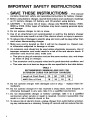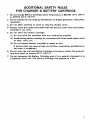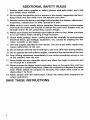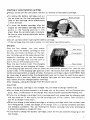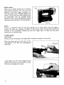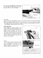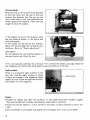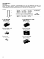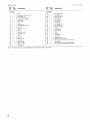
1
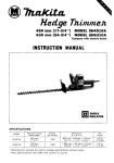
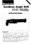
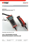
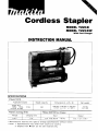
Cordless Stanler
I
MODEL T221D
MODEL T 2 2 l D W
With Fast Charger
INSTRUCTION MANUAL
SPECIFICATI0NS
Model T221D
Applicable staples
Staple Nos.
1010, 1013,
*1019, * l o 2 2
1016,
I
Staple capacity
Dimensions (L x W x H)
Net weight
100
199 mm x 58 mm x 193 m m
(7-7/8”x 2-114” x 7-518”)
1.7 kg
(3.7 Ibs)
Battery Cartridge 9100
Model DC9700 Fast Charger
Voltage
Charging time
9.6 V
1 Hr.
Input
A.C. only 50 Hz
output
~
60 Hz
D.C. 7.2 V, 9.6 V
~~~~
* M a n u f a c t u r e r reserves t h e right t o change specifications without notice.
* N o t e : 1. Specifications m a y differ f r o m c o u n t r y to country.
2. Staples with m a r k are for s o f t material only.
IMPORTANT
SAFETY INSTRUCTIONS
(For All Tools)
WARNING: WHEN USING ELECTRIC TOOLS, BASIC SAFETY
PRECAUTIONS SHOULD ALWAYS BE FOLLOWED TO REDUCE
THE RISK OF FIRE, ELECTRIC SHOCK, AND PERSONAL
INJURY, INCLUDING THE FOLLOWING:
READ ALL INSTRUCTIONS.
1. KEEP WORK AREA CLEAN. Cluttered areas and benches invite injuries.
2. CONSIDER WORK AREA ENVIRONMENT. Don't use power tools in damp
or wet locations. Keep work area well lit. Don't expose power tools t o rain.
Don't use tool in presence of flammable liquids or gases.
3. KEEP CHILDREN AWAY. All visitors should be kept away from work area.
Don't let visitors contact tool or extension cord.
4.STORE IDLE TOOLS. When not in use, tools should be stored in dry, and high
or locked-up place
-
out of reach of children.
5. DON'T FORCE TOOL. It will do the job better and safer at the rate for which
it was intended.
6.USE RIGHT TOOL. Don't force small tool or attachment t o do the job of a
heavy-duty tool. Don't use tool for purpose not intended.
7. DRESS PROPERLY. Don't wear loose clothing or jewelry. They can be caught
in moving parts. Rubber gloves and non-skid footwear are recommended
when working outdoors. Wear protective hair covering to contain long hair.
8. USE SAFETY GLASSES. Also use face or dust mask if cutting operation is
dusty.
9. DON'T ABUSE CORD. Never carry tool by cord or yank it t o disconnect from
receptacle. Keep cord from heat, oil, and sharp edges.
IO. SECURE WORK.
Use clamps or a vise t o hold work. It's safer than using
your hand and it frees both hands to operate tool.
1 1 . DON'T OVERREACH. Keep proper footing and balance at all times.
12. MAINTAIN TOOLS WITH CARE. Keep tools sharp and clean for better and
safer performance. Follow instructions for lubricating and changing accessories. Inspect tool cords periodically and if damaged, have repaired by authorized service facility. Inspect extension cords periodically and replace if
damaged. Keep handles dry, clean, and free from oil and grease.
13. DISCONNECT TOOLS. When not in use, before servicing, and when changing accessories, such as blades, bits, cutters.
2
14. REMOVE ADJUSTING KEYS AND WRENCHES. Form habit of checking t o
see that keys and adjusting wrenches are removed from tool before turning
it on.
15. AVOID UNINTENTIONAL STARTING. Don't carry plugged-in tool w i t h finger
on switch. Be sure switch is OFF when plugging in.
16. OUTDOOR USE EXTENSION CORDS. When tool is used outdoors, use only
extension cords intended for use outdoors and so marked.
17. STAY ALERT. Watch what you are doing, use common sense. Don't operate
tool when you are tired.
18. CHECK DAMAGED PARTS. Before further use of the tool, a guard or other
part that is damaged should be carefully checked t o determine that it will
operate properly and perform its intended function. Check for alignment of
moving parts, binding of moving parts, breakage of parts, mounting, and
any other conditions that may affect its operation. A guard or other part
that is damaged should be properly repaired or replaced by an authorized
service center unless otherwise indicated elsewhere in this instruction
manual. Have defective switches replaced by authorized service center. Don't
use tool if switch does not turn it on and off.
19. GUARD AGAINST ELECTRIC SHOCK. Prevent body contact w i t h grounded
surfaces. For example; pipes, radiators, ranges, refrigerator enclosures.
20. REPLACEMENT PARTS. When servicing, use only identical replacement parts.
VOLTAGE WARNING: Before connecting the tool t o a power source (receptacle,
outlet, etc.) be sure the voltage supplied is the same as that specified on the
nameplate of the tool. A power source w i t h voltage greater than that specified
for the tool can result in SERIOUS INJURY to the user - as well as damage t o
the tool. If in doubt, DO NOT PLUG IN THE TOOL. Using a power source w i t h
voltage less than the nameplate rating is harmful t o the motor.
3
I MPORTANT SAFETY
1.
SAVE THESE INSTRUCTIONS
- This manual
contains important safety and operating instructions for battery charger.
2. Before using battery charger, read all instructions and cautionary markings
on (11 battery charger, (2) battery, and (3)product using battery.
3. CAUTION - To reduce risk of injury, charge only MAKITA Battery 7000,
9000 or 9100. Other types of batteries may burst causing personal injury
and damage.
4.Do not expose charger t o rain or snow.
5. Use of an attachment not recommended or sold by the battery charger
manufacturer may result in a risk of fire, electric shock, or injury t o persons.
6. To reduce risk of damage t o electric plug and cord, pull by plug rather than
cord when disconnecting charger.
7. Make sure cord is located so that it will not be stepped on, tripped over,
or otherwise subjected t o damage or stress.
8. A n extension cord should not be used unless absolutely necessary. Use of
improper extension cord could result in a risk of fire and electric shock. If
extension cord must be used, make sure:
a. That pins on plug of extension cord are the same number, size, and shape
as those of plug on charger;
b. That extension cord is properly wired and in good electrical condition; and
c. That wire size is at least as large as the one specified in the table below.
TABLE 1
RECOMMENDED MINIMUM AWG SIZE FOR
EXTENSION CORDS FOR BATTERY CHARGERS
Length of Cord (Feet)
25
50
100
150
AWG Size of Cord
18
18
18
16
9. Do not operate charger w i t h damaged cord or plug - replace them immediately.
10. Do not operate charger if it has received a sharp blow, been dropped, or
otherwise damaged in any way; take it t o a qualified serviceman.
11. Do not disassemble charger or battery cartridge; take it t o a qualified
serviceman when service or repair is required. Incorrect reassembly may
result in a risk of electric shock or fire.
12. To reduce risk of electric shock, unplug charger from outlet before attempting any maintenance or cleaning. Turning off controls will not reduce this risk.
4
ADDITIONAL SAFETY RULES
FOR CHARGER & BATTERY CARTRIDGE
1. Do not charge Battery Cartridge when temperature is BELOW 10°C (5OOF)
or ABOVE 4OoC (104OF).
2. Do not attempt t o use a step-up transformer, an engine generator or DC power
receptacle.
3. Do not allow anything t o cover or clog the charger vents.
4. Always cover the battery terminals with the battery cover when the battery
cartridge is not used.
5. Do n o t short the battery cartridge:
(1) Do not touch the terminals with any conductive material.
(2) Avoid storing battery cartridge in a container with other metal objects such
as nails, coins, etc.
(3)Do n o t expose battery cartridge t o water or rain.
A battery short can cause a large current flow, overheating, possible burns
and even a breakdown.
6. Do not store the tool and Battery Cartridge in locations where the temperature may reach or exceed 5OoC (122OF).
7. Do not incinerate the Battery Cartridge even if it is severely damaged or is
completely worn out. The battery cartridge can explode in a fire.
5
ADDITIONAL SAFETY RULES
1. Always wear safety goggles or safety glasses w i t h side shield, and a full
face shield when needed.
2. Do not point the ejection port at anyone in the vicinity (especially his face).
Keep hands and feet away from the ejection port area.
3. Always remove the battery cartridge before loading the staples, adjustment,
inspection, maintenance or after operation is over.
4. Make sure no one is nearby before operation. Never attempt t o drive staples
from both the inside and outside of wall a t the same time. Staples may rip
through and/or fly off, presenting a grave danger.
5. Watch your footing and maintain your balance with the tool. Make sure there
is no one below when working in high locations.
6. Check walls, ceilings, floors, roofing and the like carefully t o avoid possible
electrical shock, gas leakage, explosions, etc. caused by stapling into live
wires, conduits or gas pipes.
7. Use only staples specified in this manual. The use of any other staples may
cause malfunction of the tool.
8. Do not tamper with the tool or attempt to use it for other than driving staples.
9. Do not operate the tool without staples. It shortens the service life of the tool.
IO. Stop driving operations immediately if you notice something wrong or out
of the ordinary w i t h the tool.
1 1 . Never staple into any materials which may allow the staple t o puncture and
fly through as a projectile.
12. Never actuate the trigger switch and safety lever at the same time until you
are prepared t o staple workpieces. Allow the workpiece t o depress the safety
lever. Never defeat its purpose by securing the safety lever back or by
depressing it by hand.
13. Never tamper w i t h the safety lever. Check the safety lever frequently for
proper operations.
SAVE THESE INSTRUCTIONS.
6
Installing or removing battery cartridge
Always switch off the tool before insertion or removal of the battery cartridge.
To remove the battery cartridge, pull out
the s e t plate on the tool and grasp both
sides of the cartridge while withdrawing
i t from the tool.
*To insert the battery cartridge, align the
tongue on the battery cartridge with the
groove in the housing and slip it into
place. Snap the s e t plate back into place.
Be sure to close the s e t plate fully before
using the tool.
0
0
I
Batterv cartridqe
Do not use force when inserting the battery cartridge.
If the cartridge does not slide in easily, it is not being inserted correctly.
Charging
Plug the fast charger into your power
k
Start button
source. Insert the battery cartridge so that
the plus and minus terminals on the battery cartridge are on the same sides as their
respective markings on the fast charger.
Insert the cartridge fully into the port so
that it rests on the charger port floor.
Press the start button (red). The charging
light will come on and charging will begin.
If the charging light does not come on, press the reset button (yellow) first, then the start
button (red). If the charging light goes out within 10 seconds even after pressing the reset
button and start button a couple of times, the battery cartridge is dead. (CAUTION : Wait
for more than 5 seconds after the charging light goes out t o press the reset button again.)
Replace it with a new one. When the charging light goes out after about one hour, you
may remove the fully charged battery cartridge.
After charging, unplug the charger from the power source.
CAUTION :
0Your new battery cartridge is not charged. You will need to charge it before use.
.Do not keep the button pressed in with tape, etc. or the circuit will not function properly. Also, a malfunction of the charger may result possibly causing overheating, etc.
If you try to charge a cartridge from a just-operated tool, sometimes the charging light
will not come on. If this occurs, let the cartridge cool off for a while. Then re-insert it
and try to charge it once more.
0 When you charge a new battery cartridge or a battery cartridge which has not been used
for a long period, it may not accept a full charge. This i s a normal condition and does
not indicate a problem. You can recharge the battery cartridge fully after discharging
it almost completely a couple of times.
0 If you wish to charge two battery cartridges, allow 15 minutes between chargings on the
fast charger.
7
Safety system
Make sure all safety systems are in working
order before operation. The tool must not
operate if only the trigger i s pulled or if
only the safety lever is pressed against the
wood. It must work only when both actions
are performed. Test for possible faulty
operation with a tool unloaded and pointed
well away from yourself or any bystanders.
NOTE :
There is a possibility that the tool may operate for an instant when only the trigger is
pulled. This does not indicate a problem. If this occurs, point the tool well away from
yourself or any bystanders. Release and pull the trigger again to make sure the safety
systems are in working order.
Loading staples
CAUTION:
Always remove the battery cartridge before loading the staples into the tool.
Press the plate spring on the rear of the
sub-magazine and slide the sub-magazine
backward.
Load staples into the main magazine with
staple ends facing up as illustrated a t right.
8
Plate spring
To secure the sub-magazine in place, push
the sub-magazine while pressing the plate
spring on the rear of the sub-magazine.
CAUTION :
0 Always secure the sub-magazine in place, or the staples can drop out and cause problems.
With the magazine loaded, if the tool is held downward and the sub-magazinei s opened,
the staples can fall out and present a danger to anyone or anything below. Keep this in
mind especially when working in high locations.
Depth adjustment
If the staples are driven too deep or too
shallow, adjust the driving depth by turning the nut on the bottom of the tool. For
deeper driving of staples, turn the nut
clockwise. For shallower driving, turn the
nut counterclockwise. Please note the nut
must be turned in increments of 180" (1/2
turn) so that the groove on the nut runs
parallel to the magazine.
I
I
hlllf
i
NOTE :
If the distance between the tool end (A)
and the material to be fastened is more
than 2 mm ( 5 / 6 4 " ) , the tool will not
operate because the safety lever is not
pressed enough to operate the tool.
9
Driving staples
Place the tool on the material to be fastened
so that the front and the rear of the tool
contact the material flat. Do not tip the
tool t o the right or left side. Hold the tool
firmly against the material, Then pull the
trigger to drive the staples.
If the staples are driven too shallow, press
the tool head as shown in the figure and
drive the staples.
If the staples are s t i l l driven too shallow,
adjust the driving depth by turning the nut
clockwise. Refer to "Depth adjustment".
CAUTION :
Do not operate the tool without staples. I t
shortens the service life of the tool.
If the tool becomes jammed, do as follows. First, remove the battery cartridge. Open the
sub-magazine and remove the stuck staple using a screwdriver or the like.
Sight window
There is a convenient sight window on the
tool side. Use this sight window to check
if there are staples in the magazine. When
staples are not visible through the window,
load staples into the magazine.
Staples
Handle the staples and their box carefully. If the staples have been handled roughly,
they may be bent out of shape, causing poor staple feed or jamming.
.Avoid storing the staples in a very humid or hot place or place exposed to direct sunlight.
0
0
Do not attempt to use staples that appear to be damaged, bent, rusty or corroded.
10
MAINTENANCE
CAUTION :
Always remove the battery cartridge before attempting to perform inspection or maintenance.
To maintain product SAFETY and RELIABILITY, repairs, maintenance or adjustment
should be performed by Makita Authorized or Factory Service Centers, always using
Makita replacement parts only.
11
ACCESSORIES
CAUTION :
These accessories or attachments are recommended for use with your Makita tool specified in this
manual. The use of any other accessories or attachments might present a risk of injury to persons.
The accessories or attachments should be used only in the proper and intended manner.
Staples
5,000
798377-2
I 10 (13/32") I 22 (7/8")
I
A
1 hour fast charger
Model DC9700
Part No. 113103-2
1 hour fast automotive charger
Model DC 9112
Part No. 113110-5
Battery cartridge 9100
Part No. 192019-4
Plastic carrying case
P a r t No. 182403-1
Battery cover
Part No. 41 4938- 7
15 minute fast charger
Model DC9015
Part No. 113106-6
12
Jan - 2 1 -
92 US
CORDLESS STAPLER
Model T221D
Note: The switch and other part configurations
may differ from country to country.
13
MODEL T221D
'i\M
Jan.-21--'92
'L5M
DESCRIPTION
AtD
DESCRIPTION
__
3
4
5
6
7
1
1
1
1
1
6
9
1
1
1
10
11
12
13
14
15
16
17
18
19
20
22
23
24
1
1
1
1
1
1
1
1
1
1
1
1
1
1
25
1
21
Note The switch
14
Switch
Housing Set iWlth Item 451
Flat Washer 9
Compression Spring 9
Compression Spring 1 3
Guide Plate
Driver Lock
P,n 4
Safety Lever
Compression Spring 3
Hammer
Spring Pin 4 - 1 4
Plate
Sleeve 4
Helical Gear 53
Flat Washer 1 0
P," 10
set Plate
P," 3
Release Plate
Leaf spring
Switch Lever
Battery Holder
Battery 9100
Hand Strao
38
1
1
1
1
1
1
1
1
1
1
1
1
1
39
40
41
42
43
44
1
1
1
1
1
1
45
46
47
48
49
1
6
1
3
26
27
28
29
30
31
32
33
34
35
36
37
2
I
and other part specofcattons may differ from country to country
D C Motor 9 6 V
Flat Washer 1 2
Infernal Gear 69
Spur Gear 2 1
Spur Gear 27
Spur Gear 27
Leaf sprtng
Helical Gear 7
Flat Washer 10
Plane Bearing 1 0
Tenslo" Sprrng 4
Cushion
Pusher Guide
Driver Guide
Dwer
Pusher
Sub Magalme
Nut M 4
Magazine Lock
Housing S e t (With Item 21
I Pan Head Screw M4x22 IWith Waaherl
Name Plale
Pan Head Screw M4x14 (With Washer1
Pan Head Screw M4x30 (With Washer1
I
US
MAKITA LIMITED ONE YEAR WARRANTY
Warranty Policy
Evcry Makita tool is thoroughly inspected and tested before leaving the factory. It is warranted to
be free of defects from workmanship and materials for the period of ONE YEAR from the date of
original purchase. Should any trouble develop during this one-year period, return the COMPLETE
tool, freight prepaid, t o one of Makita’s Factory or Authorized Service Centers. If inspection shows
the trouble is caused by defective workmanship or material, Makita will repair (or at our option,
replace) without charge.
This Warranty does not apply where:
repairs have been made or attempted by others:
repairs are required because of normal wear and tear:
The tool has been abused, misused or improperly maintained;
alterations have been made to the tool.
I N NO EVENT SHALL MAKITA BE LIABLE FOR ANY INDIRECT, INCIDENTAL OR CONSEQUENTIAL DAMAGES FROM THE SALE OR USE OF THE PRODUCT. THIS DISCLAIMER
APPLIES BOTH DURING AND AFTER THE TERM OF THIS WARRANTY.
MAKITA DISCLAIMS LIABILITY FOR ANY IMPLIED WARRANTIES, INCLUDING IMPLIED
WARRANTIES OF “MERCHANTABILITY” AND “FITNESS FOR A SPECIFIC PURPOSE,”
AFTER THE ONE-YEAR TERM OF THIS WARRANTY.
This Warranty gives you specific legal rights, and you may also have other rights which vary from
state to state. Some states d o not allow the exclusion or Limitation of incidental or consequential
damages, so the above limitation or exclusion may not apply to you. Some states do not allow
limitation on how long an implied warranty lasts, so the above limitation may not apply to you.
Makita Corporation
3-11-8, Sumiyoshi-cho,
Anjo, Aichi 446 Japan
883849
- 063
PRINTED IN JAPAN
1993-4-N