1
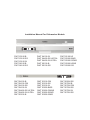
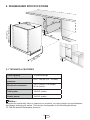
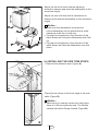
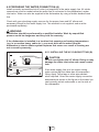
Dishwasher Installation Manual FOR MODELS DWT 23100 B DWT 23100 SS DWT 23100 W DWT 24100 B DWT 24100 SS DWT 24100 W DWT 24400 SS ULTRA DWT 24400 W ULTRA DWT 25100 B DWT 25100 SS DWT 25100 W DWT 25200 BWS DWT 25200 SSWS DWT 25200 WWS DWT 25500 SS DWT 54100 B DWT 54100 FBI DWT 54100 SS DWT 54100 W DWT 54400 SS ULTRA DWT 54400 W ULTRA DWT 55100 B DWT 55100 FBI DWT 55100 SS DWT 55100 W DWT 55200 BWS DWT 55200 FBIWS USA DWT 55200 SSWS DWT 55200 WWS DWT 55500 SS DWT 57500 B DWT 57500 FBI DWT 57500 SS DWT 57500 W DWT 57550 SS Installation Manual For Dishwasher Models Cycle Select Start / Pause Half Load / Tablet Time Delay DWT 23100 B DWT 23100 SS DWT 23100 W DWT 24100 B DWT 24100 SS DWT 24100 W DWT 24400 SS ULTRA DWT 24400 W ULTRA DWT 25100 B DWT 25100 SS DWT 25100 W DWT 25200 BWS DWT 25200 SSWS DWT 25200 WWS DWT 25500 SS DWT 54100 B DWT 54100 FBI DWT 54100 SS DWT 54100 W DWT 54400 SS ULTRA DWT 54400 W ULTRA DWT 55100 B DWT 55100 FBI DWT 55100 SS DWT 55100 W DWT 55200 BWS DWT 55200 FBIWS DWT 55200 SSWS DWT 55200 WWS DWT 55500 SS DWT 57500 B DWT 57500 FBI DWT 57500 SS DWT 57500 W DWT 57550 SS To prevent accidents, which could cause serious injury or death, as well as machine damage read these instructions before installation and / or use. Contents 1. IMPORTANT SAFETY INSTRUCTIONS 1 1.1 INSPECT THE DISHWASHER 1.2 HOW TO CONTACT US 2 2 2. TOOLS WHICH MAY BE NEEDED 3 3. MATERIALS WHICH MAY BE NEEDED 3 4. MATERIALS SUPPLIED 4 4.1 PARTS SUPPLIED 4.2 MANUAL BAG 4.3 DISHWASHER PARTS BAG 1 4.4 DISHWASHER PARTS BAG 2 4.5 PARTS ATTACHED TO THE REAR OF THE DISHWASHER 4 4 4 4 4 5. DISHWASHER SPECIFICATIONS 5 5.1 TECHNICAL FEATURES 5 6. ENCLOSURE PREPARATION 6 6.1 ELECTRICAL PREPARATION 6.2 PREPARATION FOR INSTALLING MOUNTING BRACKETS 6.3 ADJUSTING HEIGHT 6.4 INSTALLING THE SIDE TRIM STRIPS 6.5 PREPARING THE WATER CONNECTION (A) 6.6 DRAIN PREPARATION 6.7 STEAM PROTECTION FOIL 6 6 6 7 8 9 10 7. PLACEMENT OF DISHWASHER INTO THE OPENING 11 7.1 DRAIN HOSE CONNECTION, WATER SUPPLY & ELECTRICAL CONNECTIONS 7.2 READJUSTING FOOT LEVELS 7.3 ADJUSTING THE MOVABLE TOE KICK 7.4 INSTALLING THE OUTER DOOR 11 15 15 16 8. INSTALLER CHECKLIST 22 9. FINAL INSTRUCTIONS 22 10. SELF HELP HINTS 22 INTRODUCTION WARNING Please read this installation manual and particularly the safety instructions completely and carefully. They will save you time and effort and help to ensure optimum dishwasher performance. Be sure to observe all listed warnings and cautions. Look particularly for the icons with exclamation marks inside. The information icon also will provide important references. WARNING Ý CAUTION Notice WARNING: Indicates a potentially hazardous situation which, if not avoided, could result in death or serious injury. CAUTION: Indicates a potentially hazardous situation which, if not avoided, may result in injury. It may also be used to alert against unsafe practices. Notice: Indicates a potentially hazardous situation which, if not avoided, may result in damage to the dishwasher, the table-ware, the equipment or the environment. 1. IMPORTANT SAFETY INSTRUCTIONS In addition to these instructions, the dishwasher shall be installed: • In accordance with all local codes or, in absence of a local code, • In the United States, with the National Electric Code, • In Canada, with the Canadian Electric Code C22.1-latest edition/Provincial and Municipal codes and/or local codes. Notice : Read these installation instructions completely before installing and follow them carefully. Save these installation instructions and pass them on to any future user. 1 When installing the dishwasher, follow basic precautions, including the following: • The dishwasher installation must be performed in accordance with this installation manual. If you did not receive an installation manual, order it by calling 1-800-459-9848 or you may also download it from our web site at www.blombergappliances.com • The dishwasher could only be converted from cord-connected to permanently connected by an authorized service representative. (If needed contact your dealer to schedule an authorized service agent for conversion with an appropriate conversion kit) • Installation and repair should be performed by a qualified installer. Work by unqualified persons could be dangerous and may void the warranty. Notice : Installation should be installed by an insured licensed plumber, contractor or trained installer. Installation performed by persons other than this could result in improper installation and property damage. • Do not operate the appliance if damaged, malfunctioning, partially disassembled or if it has missing or broken parts. • Also follow the safety instructions of the user manual. • To reduce the risk of electric shock, fire, or injury to persons, the installer must ensure that the dishwasher is completely enclosed at the time of installation. • Only connect the dishwasher to the power supply when all installation and plumbing work is complete. • If the dishwasher is installed in a location that experiences freezing temperatures (e.g. in a vacation home, cabin, etc.), you must drain all the water from the dishwasher’s interior. Water system ruptures that occur as a result of freezing are not covered by warranty. USA • Replacement - If the dishwasher is replacing another dishwasher, check the existing dishwasher connections for compatibility with the new dishwasher, and replace parts as necessary. • Dishwasher must be secured to adjacent cabinetry using the brackets provided. Failure to do this may cause damage to property or bodily injury. • Connect to a properly rated, protected and sized power supply circuit to avoid electrical overload. The dishwasher is designed for an electrical supply of 120 V (volts), 60 Hz (hertz), AC, connected to a dishwasher-dedicated, properly grounded electrical circuit with a fuse or breakers rated for 15 amperes. Electrical supply conductors shall be a minimum of # 16 AWG copper wire rated at 75 °C (167 °F) or higher. These requirements must be met to prevent injury and machine damage. Consult a qualified electrician if in doubt. • Do not use any extension cord or portable outlet device to connect the dishwasher to a power supply. • Ensure that any plastic wrappings, bags, small pieces etc. are disposed of safely and kept out of the reach of children. Danger of suffocation! • Remove the door to the washing compartment when removing an old dishwasher from service or discarding it. Ensure that the appliance presents no danger to children while being stored for disposal. • Old appliances may contain materials that can be recycled. Please contact your local recycling authority about the possibility of recycling these materials. 1.1 INSPECT THE DISHWASHER After unpacking the dishwasher and prior to installation, thoroughly inspect the dishwasher for possible freight or cosmetic damage. Report any damage immediately. Notice : • Cosmetic defects must be reported within 10 days of installation. • Do not discard any bags or items that come with the original package until after the entire installation has been completed. 1.2 HOW TO CONTACT US : You may either call our Toll Free Number at 1-800-459-9848 or contact us via the web site at www.blombergappliances.com or Contact the Blomberg Distributor for your State or Province as listed on the Distributor Contact List provided. Notice : • The dishwasher drain hose must be installed with a drain loop at least 28” (710mm) off the cabinet floor; otherwise the dishwasher may not drain properly. • This dishwasher is intended for residential use only, and should not be used in commercial establishments. • New installation - If the dishwasher is a new installation, most of the work must be done before the dishwasher is moved into place. 2 USA 2. TOOLS WHICH MAY BE NEEDED 3. MATERIALS WHICH MAY BE NEEDED (Additional materials may be required to comply with local codes) Hot Water Supply Line - Minimum 3/8” O.D. copper tubing or metal braided dishwasher supply line. 90° elbow with 3/8” N.P.T. male threads on one leg, and sized to fit your water supply line (copper tubing/compression fitting, or braided hose) on the other leg. UL listed conduit connector or strain relief. Teflon tape or other pipe thread compound to seal plumbing connections. Shut-off valve and fittings appropriate for hot water supply line (copper tubing/compression fitting, or braided hose). Silicone Glue 3 USA 4. MATERIALS SUPPLIED 4.1 PARTS SUPPLIED a. x1 b. x1 Parts for your dishwasher will come in several plastic bags. Check your parts bags shown to make sure you have all the parts as listed to the left. c. x1 4.2 MANUAL BAG d. x6 e. x1 The dishwasher comes with a manual bag containing: • User manual, • Installation manual and • Quick reference guide. f. x1 4.3 DISHWASHER PARTS BAG 1 g. x1 h. x1 j. x1 k. x1 l. x1 m. x1 n. x2 o. x1 p. x1 This dishwasher bag comes with the following parts: a. Side Trim Strips (Left) b. Side Trim Strips (Right) c. Adjusting Wrench d. Screws Ø 1/8” x 5/8” (Ø 3.5 mm x 14 mm) e. Mounting Bracket Left f. Mounting Bracket Right g. Spring Clamp h. Screw Clamp j. Rubber Connector k. Toe Kick Bracket - Left l. Toe Kick Bracket – Right m. Edge Protector n. Clips o. Toe Kick (toe kick without slots) p. Toe Kick r. Screws Ø 1/8” x 3/8” (Ø 3.9 mm x 9 mm) s. Plastic Caps t. Screws Ø 3/16” x 1/4” (Ø 4mm x 6mm) z. Steam Protection Foil r. x2 4.4 DISHWASHER PARTS BAG 2 s. x2 t. x2 v. x4 y. x4 z. x1 In addition to the manual bag and the dishwasher parts bag 1 DWT 54, DWT 55, and DWT 57 (dishwasher models which can accept a wooden kitchen door) also come with a door panel installation kit which contains: v. Screws Ø 1/8” x 5/8” (Ø 3.5mm x 14mm) y. Screws Ø 3/16” x 13/4” (Ø 4mm x 43mm) 4.5 PARTS ATTACHED TO THE REAR OF THE DISHWASHER a. Side Trim Strips (Left) b. Side Trim Strips (Right) o. Toe Kick (toe kick without slots) p. Toe Kick 4 USA 34 - 361/4 (864mm - 920mm) 5. DISHWASHER SPECIFICATIONS 33 7/8- 35 7/8 (861mm - 911mm) 239 (598 /16 mm ) 24m) 0m (61 2 (61 4 0m m) max 500mm axax) mm 24 m 0m 61 ( 5.1 TECHNICAL FEATURES Load capacity 12 place settings Permissible water pressure 4.35 - 145 psi (0.3 - 10 bars) Electrical connection 120 V (volts), 12 A (amps), 60 Hz (hertz) Total power 1400 W (watts) Heater power 1240 W (watts) Notice : Because we continually strive to improve our products, we may change our specifications and design without prior notice. This device corresponds to the following directives: UL 749 Household Dishwasher directive. 5 USA 6. ENCLOSURE PREPARATION 6.1 ELECTRICAL PREPARATION WARNING The dishwasher is designed for an electrical supply of 120 V, 60 Hz, AC, connected to a dishwasher-dedicated, properly grounded electrical circuit with a fuse or breaker rated for 15 amperes. 6.2 PREPARATION FOR INSTALLING MOUNTING BRACKETS WARNING Dishwasher must be secured to adjacent cabinetry using the mounting brackets provided. Failure to do this may cause damage to property or bodily injury. A B Place the two mounting brackets into the top corners of the dishwasher. Fix the mounting brackets (A) to the top corners of the dishwasher, with the screws supplied. Bend sides of mounting brackets (B) in order to fix from sides (if necessary). B A If the height of the enclosure is 337/8” to 357/8” (861 mm - 911mm) adjust supports as shown in the figure. (861mm - 911mm) 33 7/8- 35 7/8 6.3 ADJUSTING HEIGHT Supplied (4) 115/16 (50mm) 6 USA Adjust the front foot level with the adjusting wrench to balance and raise the dishwasher to the enclosure height. Adjust the rear foot level with a screwdriver to balance and raise the dishwasher to the enclosure height. Notice : • Make sure the dishwasher is plumb and notice dishwasher can be placed with a small clearance under the counter top. • Turning the screwdriver in the direction of the black arrows will bring the dishwasher back feet up. • Turning the screwdriver in the direction of the white arrows will take the dishwasher rear feet down. T20 6.4 INSTALLING THE SIDE TRIM STRIPS 1. Remove the adhesive tape (Figure A). A Place the trim strips on the front edge of the side walls (Figure B). Notice : • Make sure you use the correct trim strip since there is a left and right side strip. The flexible material should be facing forward (Figure B). B 7 USA 6.5 PREPARING THE WATER CONNECTION (A) Install an easily accessible shut-off valve (not supplied) in the water supply line. All solder connections must be made before the water line is connected to the dishwasher’s water inlet valve. Water can also be supplied to the dishwasher by using a flexible braided hose line. Check with your plumbing supply sources for the proper hose and 90° elbow and necessary fittings for the water supply line. This material is not supplied, and must be purchased separately. WARNING Installation should be performed by a qualified installer. Work by unqualified persons could be dangerous and may void the warranty. If the dishwasher is installed in a location that experiences freezing temperatures (e.g. in a vacation home, cabin etc.), you must drain all the water from the dishwasher’s interior. Water system ruptures that occur as a result of freezing are not covered by warranty. 6.5.1 INSTALLING THE 90° ELBOW FITTING (B) B CAUTION Do not over tighten the 90° elbow. Doing so may damage the water inlet valve and cause a water leak. A If the water supply line is to be copper tubing, make certain that the elbow has a compression fitting. Apply Teflon tape or other pipe sealant when required. Orient the water supply connection downwards as shown in the figure so the water line can be easily pulled underneath or on the side of the dishwasher. 8 USA 6.6 DRAIN PREPARATION The dishwasher drain hose may be connected to the drain plumbing in one of three ways (Figure A, B, C). Notice : • Either one of the above methods must be used or the dishwasher will not operate properly. • A hose that attaches to a sink spray can burst if it is installed on the same water line as the dishwasher. If your sink has one, it is recommended that the hose be disconnected and the hole plugged. • The total length of the drain hose is 763/4” (1950mm). If a hose extension is required, a drainage hose of equal quality must be used. • The maximum length must not exceed 157 ½” (4000mm). Otherwise, the cleaning process is negatively influenced. 6.6.1 UNDER THE SINK DRAIN Install a Y-branch tail pipe. (Figure A) Notice : A • You must add a loop at least 28” (710mm) above the floor of the cabinet and above the drain connection in the drain hose to prevent waste water from not draining properly, and causing either poor washing results or a bad odor. 6.6.2 INSTALLING AN AIR GAP If the local ordinance requires an air gap (Figure B). Notice : • Check with local ordinance for type of air gap required. B 6.6.3 DISPOSAL Remove the drain connection plug before attaching the drain hose from the dishwasher. Every disposal has a hook up for a dishwasher; consult your disposer manual for correct connection. (Figure C) C 9 USA 6.7 STEAM PROTECTION FOIL Steam will form inside the dishwasher during operation. At the end of the cycle, when the dishwasher door is opened, it is required to use a steam protection foil to prevent any steam from collecting on the underside of the counter top. 6.6.2 FITTING THE PROTECTION FOIL Before applying the steam protection foil to the underside of the countertop, clean the area with a damp cloth (as shown in Figure A). Once the area dries, apply the steam protection foil. A The steam protection foil will be applied at the location where the hot steam escapes when you first open the door (as shown in Figure B). B CAUTION Steam protection foil must be applied where the steam escapes when door is first opened. Failure to install the steam protection foil during installation can lead to damage to the cabinets and countertop. 10 USA 7. PLACEMENT OF DISHWASHER INTO THE OPENING Now place the dishwasher into the opening and get ready to connect all hoses and electrical connections. CAUTION Make sure all hoses are pulled through the side opening of the cabinet, no hoses are kinked and all slack is taken out as shown in the above figure. 7.1 DRAIN HOSE CONNECTION, WATER SUPPLY & ELECTRICAL CONNECTIONS 7.1.1 DRAIN HOSE CONNECTION Connect the drain hose to the drain plumbing. 1. Use the supplied rubber connection hose and drain hose clamps to connect the dishwasher drain hose to the plumbing drain connection. 2. Use the spring clamp to secure the rubber connection hose to the dishwasher drain hose. Use the screw clamp to secure the rubber connection hose to the plumbing drain connection. Note that the marks on the rubber connection hose should be on the drain hose side 11 USA 7.1.2 PREPERATION OF WATER SUPPLY Left side water supply connection A Before pushing the dishwasher in to the cabinet you must place water supply hoses into the channel of the dishwasher (Figure A). Place the supplied clips into the channel (Figure B) so that you can move these clips along the channel (Figure C) and fix by pressing on (Figure D) so that you can keep the water supply hose in the channel. B C D 12 USA After installing one clip for each side push the dishwasher into the cabinet (Figure E). E Note that while pushing the dishwasher into the cabinet, water supply hose must move in the channel to the front (Figure F). F Fix the second clip (Figure G). G 13 USA 7.1.3 WATER SUPPLY CONNECTION Water supply may be connected to the dishwasher in one of two ways: • With metal braided hose. • With copper tubing. CAUTION • Hot water supply line: Use minimum 3/8” O.D. copper tubing or metal braided dishwasher supply line. • Temperatures required for soldering and sweating will damage the dishwasher’s water inlet valve so if any such operation is needed, keep the heat source min. 77/8” (200mm) away from the dishwasher’s water inlet valve. • There should not be any sharp bends in the water line that may restrict the water flow. • Teflon tape or pipe tread compound must be used for sealing the connection. Before connecting the copper water supply line to the dishwasher, flush it with hot water to clear any foreign material. Notice : After connections are made turn on the water supply to check for leaks. 7.1.4 ELECTRICAL CONNECTION WARNING • Make sure the voltage and frequency listed on the data plate correspond with the household electrical supply. This data must correspond to prevent injury and machine damage. Consult a qualified electrician if in doubt. • Only connect the dishwasher to the mains when all installation and plumbing work is complete. • Do not use any extension cord or portable outlet device to connect the dishwasher to a power supply. • The power-supply receptacle for the appliance shall be installed in a cabinet or on a wall adjacent to the undercounter space in which the appliance is to be installed. • The access hole of the supply cord to the installation compartment must be smooth and rounded and it must be large enough for the attachment plug to pass through. The longest dimension of the opening shall not be more than 1,5” (38 mm).If the partition is metal, it needs to be covered with an edge protector. • Care must be taken when the appliance is installed or removed, to reduce the likelihood of damage to the power-supply cord. 7.1.5 GROUNDING INSTRUCTIONS This appliance must be grounded. In the event of a malfunction or breakdown, grounding will reduce the risk of electric shock by providing a path of least resistance for electric current. This appliance is equipped with a cord having an equipment-grounding conductor and a grounding plug. The plug must be plugged into an appropriate outlet that is installed and grounded in accordance with all local codes and ordinances. This appliance must be connected to a grounded metal, permanent wiring system, or an equipment-grounding conductor must be run with the circuit conductors and connected to the equipment-grounding terminal or lead on the appliance. WARNING • Improper connection of the equipment-grounding conductor can result in a risk of electric shock. Check with a qualified electrician or service representative if you are in doubt whether the appliance is properly grounded. Do not modify the plug provided with the appliance, if it will not fit the outlet, have a proper outlet installed by a qualified electrician. 14 USA 7.2 READJUSTING FOOT LEVELS Now that the dishwasher is in the cabinet you must readjust the feet to bring the dishwasher up to the required height and attach it underneath the countertop. Ø 1/8" (3,5mm) Ø 1/8" (3,5mm) 1. Readjust the front foot levels with adjusting wrench to balance the dishwasher and raise it up under the countertop, make sure the unit is level. 2. Readjust the rear foot levels with a screwdriver to balance the dishwasher and raise it to the required height using the brackets supplied. 3. Attach the dishwasher underneath the countertop with the four screws supplied (Ø 1/8” x 1/8” - Ø 3.5mm x 14mm). Make sure you do not go through the top of the countertop or damage granite. 7.3 ADJUSTING THE MOVABLE TOE KICK Now that you have successfully installed the dishwasher, you need to attach the toe kick to the dishwasher. The two piece toe kick can be adjusted to the height and depth needed for your kitchen. Be sure to use the slotted toe kick in the front and the other behind it. They slide into each other. A 1. Insert the movable toe kick brackets into the channel (A). 2. Make sure that the plastic tab to the left of the “L” opening on the dishwasher has not closed the channel you will push the bracket through. B Notice : Be sure to notice there is a left and a right bracket. Adjust the toe kick brackets forward or backwards so that they will align with the kitchen toe kick (B). Lock the toe kick brackets as shown with the plastic tab in the figure C by pushing the plastic tab on the dishwasher into the teeth of the bracket (C). 3. Now attach the toe kick to the bracket with the two (Ø 3/16” x 1/4” - Ø 4mm x 6mm) screws and the caps provided as follows. 15 USA C o A B t s C If the enclosure height is above 331/16” (840mm) use “o” and “p” labelled toe kicks together. Make sure the slotted toe kick “p” is on the outside so you can adjust height of the toe kick. Installation should be done following the steps illustrated in the figures A, B and C respectively. 1. Align the toe kick (o) and (p) (A). 2. Secure toe kicks to brackets with screws (t) after adjusting the height of the slotted toe kick (p) (B). 3. Attach caps (s) as shown in the supply bags (C). If the enclosure height is below 331/16” (840mm) use only “o” labelled toe kick (toe kick without slots). Installation should be done following the steps illustrated in the Figures A, B and C respectively. 1. Bend tabs on toe kick (o) inwards (A). 2. Secure toe kick to brackets with screws (t) as shown in the supply bags (B). 3. Attach caps (s) as shown in the supply bags (C). A o p B t s C 7.4 INSTALLING THE OUTER DOOR (DWT 54100 FBI, DWT 55100 FBI, DWT 55200 FBIWS, DWT 57500 FBI) ? ? A Measure the height and width of the enclosure (Figure A) and the toe kick. Determine how big the wooden door can be. For example if the height is 337/8” (860mm) and if the toe kick is 315/16” (100mm) the door can not be taller than 2915/16” (760mm). 1. Prepare the wooden door with the mounting brackets. Height : Height of the wooden door 30” (760mm) Width : 23 ¼” to 23 ½” (592mm - 595mm) Thickness : ¾ “ (19mm) 16 USA 2. Remove the plastic mounting brackets from the dishwasher (Figure B). B 3. Mark the wooden door as shown in the drawing (Figure C). ) 1/2 6 mm 5 5 (1 165mm Mid. Point Max : 12,1 lb (5,5 kg) C D 4. Place the plastic mounting brackets over the marked holes and the side tabs must be flush with the edge of the wooden door (Figure D). D 17 USA Ø 1/8" (3,5mm) 5. Attach the two mounting brackets to the wooden door with 4 screws (Ø 1/8” x 5/8” (Ø 3.5mm x 14mm) (Figure A). x4 v A 6. Mount the wooden door onto the dishwasher with the plastic mounting brackets which you have attached (Figure B). B 7. Open the door and remove the two caps and two screws inside the door at position 1 and 4 (Figure C). C 18 USA 8. Using the four screws Ø 3/16” x 111/16” (Ø 4mm x 43mm) provided, attach the wooden door to the dishwasher at position 1 and 4 (Figure A). Ø 3/16" (4mm) x4 y A 9. Check the position of the wooden door and make sure it is aligned properly (Figure B). B 10. Tighten the screws in position 1 and 4 completely after the final alignment (Figure C). Ø 3/16" (4mm) x4 y C 19 USA 11. Check whether the bottom of the door hits the toe kick of the kitchen cabinet (A). 11.1. If the door hits the toe kick cut the necessary section out of the toe kick (B). 11.2. Apply silicon or sealant to the cut edge of the kitchen cabinet toe kick or paint so it does not absorb moisture. A B ADJUSTING DOOR TENSION WITH CUSTOM WOODEN DOOR (DWT 54100 FBI, DWT 55100 FBI, DWT 55200 FBIWS, DWT 57500 FBI) Check the door tension of the dishwasher: If the door closes too quickly or if the door falls open, the spring tension needs to be adjusted. C The adjustment screws can be found on the front of the dishwasher after you open the door (see drawing). Adjust the spring tension by turning the screw to the right for more weight and to the left for less weight (Figure C). 0 kg 20 USA Notice : If you have a European kitchen or want to install a wooden toe kick to match your kitchen, please refer to one of the two drawings given below. Follow the same instructions on the brackets as for the removable toe kick. Installation should be done following the steps illustrated in the figures A, B, C, D respectively. See also page 15 B C d Ø 1/8" (3,5mm) A 7 / 16 m) 21 44m (5 3/8 (10mm) 19 / 16 4 0m D m See also page 20 A B C Notice : The installer is responsible for the dishwasher installation. Incorrect installation is not covered by the warranty. 21 USA 8. INSTALLER CHECKLIST 10. SELF HELP HINTS: Your installer must have completed and checked the following: • The dishwasher is square and level. • The dishwasher is fastened securely to the cabinetry. • The dishwasher door opens and closes freely. The dishwasher door must close without hitting any cabinetry or counter top. • The inlet water supply is turned on and checked for leaks. • The drain hose has been connected and checked for leaks. There must be no kinks or obstructions in the drain hose. • The drain hose must be installed with a 28" (710mm) high drain loop for drain hook-ups without any air removed. • If the dishwasher drain is hooked up to a garbage disposal, the drain hopper plug must be removed. • The spray arms are free and rotate freely. • The rinse cycle has been run. • The water level will be below the filter screen after the end of the wash program. It is normal to find some water in the drain filter area. • Set the water softener to the correct water hardness for your area. If the dishwasher drain is connected to a garbage disposal, make sure that the drain/hopper plug has been removed. The screen does not come on: • Check to make sure the breaker to the dishwasher is in the on position. • Check to make sure that the Supply cord is plugged. 9. FINAL INSTRUCTIONS 1. Press the On/Off button to turn the dishwasher on. 2. Power indicator light comes on. 3. Use the Program Select button to choose a washing program. 4. Start the program with the Start/Pause/ Cancel button. 5. Run the dishwasher through one complete cycle. When the wash cycle is completed, use the On/Off button to turn the dishwasher off. No Water is coming into the dishwasher: • Check to make sure the hot water shutoff is in the ON position. Water does not drain: • Make sure drain hose is not kinked or comes out of air gap next to the sink. • Remove drain hose from disposal making sure plug is removed. Notice : • If your dishwasher is not operating properly after following these steps: Contact your dealer to schedule an authorized service agent to inspect your new dishwasher for any function related failure. • The manufacturer warranty does not cover installation, conversion or customer education service visits. DWT xxxxx xxxxx uSM or uF5 You will find the model and serial number information on the label located on the right-hand side of the inner door of your dishwasher, as shown above. Notice : Please make a copy of your invoice and keep it with this manual and register your dishwasher on-line. Notice : If the dishwasher does not operate properly, refer to the self help hints. 22 USA 17 9077 01 00-AB-USA