1
SERVICE MANUAL
Color Inkjet Printer
EPSON STYLUS PHOTO 895/785EPX
®
SEIJ01001
Download Free Service Manual and Resetter Printer at http://printer1.blogspot.com
Notice
All rights reserved. No part of this manual may be reproduced, stored in a retrieval system, or transmitted in any form or by any means electronic,
mechanical, photocopying, or otherwise, without the prior written permission of SEIKO EPSON CORPORATION.
All effort have been made to ensure the accuracy of the contents of this manual. However, should any errors be detected, SEIKO EPSON would
greatly appreciate being informed of them.
The contents of this manual are subject to change without notice.
All effort have been made to ensure the accuracy of the contents of this manual. However, should any errors be detected, SEIKO EPSON would
greatly appreciate being informed of them.
The above not withstanding SEIKO EPSON CORPORATION can assume no responsibility for any errors in this manual or the consequences
thereof.
EPSON is a registered trademark of SEIKO EPSON CORPORATION.
General Notice:
Other product names used herein are for identification purpose only and may be trademarks or registered trademarks of their
respective owners. EPSON disclaims any and all rights in those marks.
Copyright © 2001 SEIKO EPSON CORPORATION.
Imaging & Information Product Division
TPCS Quality Assurance Dept.
Download Free Service Manual and Resetter Printer at http://printer1.blogspot.com
PRECAUTIONS
Precautionary notations throughout the text are categorized relative to 1)Personal injury and 2) damage to equipment.
DANGER
Signals a precaution which, if ignored, could result in serious or fatal personal injury. Great caution should be exercised in performing
procedures preceded by DANGER Headings.
WARNING
Signals a precaution which, if ignored, could result in damage to equipment.
The precautionary measures itemized below should always be observed when performing repair/maintenance procedures.
DANGER
1.
ALWAYS DISCONNECT THE PRODUCT FROM THE POWER SOURCE AND PERIPHERAL DEVICES PERFORMING ANY MAINTENANCE OR REPAIR
PROCEDURES.
2.
NO WORK SHOULD BE PERFORMED ON THE UNIT BY PERSONS UNFAMILIAR WITH BASIC SAFETY MEASURES AS DICTATED FOR ALL ELECTRONICS
TECHNICIANS IN THEIR LINE OF WORK.
3.
WHEN PERFORMING TESTING AS DICTATED WITHIN THIS MANUAL, DO NOT CONNECT THE UNIT TO A POWER SOURCE UNTIL INSTRUCTED TO DO
SO. WHEN THE POWER SUPPLY CABLE MUST BE CONNECTED, USE EXTREME CAUTION IN WORKING ON POWER SUPPLY AND OTHER ELECTRONIC
COMPONENTS.
4. WHEN DISASSEMBLING OR ASSEMBLING A PRODUCT, MAKE SURE TO WEAR GLOVES TO AVOID INJURIER FROM METAL PARTS WITH SHARP EDGES.
WARNING
1.
REPAIRS ON EPSON PRODUCT SHOULD BE PERFORMED ONLY BY AN EPSON CERTIFIED REPAIR TECHNICIAN.
2.
MAKE CERTAIN THAT THE SOURCE VOLTAGES IS THE SAME AS THE RATED VOLTAGE, LISTED ON THE SERIAL NUMBER/RATING PLATE. IF THE
EPSON PRODUCT HAS A PRIMARY AC RATING DIFFERENT FROM AVAILABLE POWER SOURCE, DO NOT CONNECT IT TO THE POWER SOURCE.
3.
ALWAYS VERIFY THAT THE EPSON PRODUCT HAS BEEN DISCONNECTED FROM THE POWER SOURCE BEFORE REMOVING OR REPLACING
PRINTED CIRCUIT BOARDS AND/OR INDIVIDUAL CHIPS.
4.
IN ORDER TO PROTECT SENSITIVE MICROPROCESSORS AND CIRCUITRY, USE STATIC DISCHARGE EQUIPMENT, SUCH AS ANTI-STATIC WRIST
STRAPS, WHEN ACCESSING INTERNAL COMPONENTS.
5.
DO NOT REPLACE IMPERFECTLY FUNCTIONING COMPONENTS WITH COMPONENTS WHICH ARE NOT MANUFACTURED BY EPSON. IF SECOND
SOURCE IC’S OR OTHER COMPONENTS WHICH HAVE NOT BEEN APPROVED ARE USED, THEY COULD CAUSE DAMAGE TO THE EPSON PRODUCT,
OR COULD VOID THE WARRANTY OFFERED BY EPSON.
Download Free Service Manual and Resetter Printer at http://printer1.blogspot.com
About This Manual
This manual describes basic functions, theory of electrical and mechanical operations, maintenance and repair procedures of the printer. The instructions and
procedures included herein are intended for the experienced repair technicians, and attention should be given to the precautions on the preceding page.
Manual Configuration
Symbols Used in this Manual
This manual consists of six chapters and Appendix.
CHAPTER 1. PRODUCT DESCRIPTIONS
Provides a general overview and specifications of the
product.
CHAPTER 2. OPERATING PRINCIPLES
Describes the theory of electrical and mechanical
operations of the product.
CHAPTER 3. TROUBLESHOOTING
Describes the step-by-step procedures for the
troubleshooting.
CHAPTER 4. DISASSEMBLY / ASSEMBLY
Describes the step-by-step procedures for disassembling
and assembling the product.
CHAPTER 5. ADJUSTMENT
Provides Epson-approved methods for adjustment.
CHAPTER 6. MAINTENANCE
Provides preventive maintenance procedures and the
lists of Epson-approved lubricants and adhesives
required for servicing the product.
APPENDIX Provides the following additional information for
reference:
• Connector pin assignments
• Electric circuit boards components layout
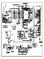
• Electrical circuit boards schematics
• Exploded diagram & Parts List
Various symbols are used throughout this manual either to provide
additional information on a specific topic or to warn of possible danger
present during a procedure or an action. Be aware of all symbols when
they are used, and always read NOTE, CAUTION, or WARNING
messages.
A D J U S T M E N T
R E Q U IR E D
C A U T IO N
Indicates an operating or maintenance procedure, practice
or condition that, if not strictly observed, could result in
injury or loss of life.
Indicates an operating or maintenance procedure, practice,
or condition that, if not strictly observed, could result in
damage to, or destruction of, equipment.
C H E C K
P O IN T
May indicate an operating or maintenance procedure,
practice or condition that is necessary to accomplish a task
efficiently. It may also provide additional information that is
related to a specific subject, or comment on the results
achieved through a previous action.
W A R N IN G
I.ndicates an operating or maintenance procedure, practice
or condition that, if not strictly observed, could result in injury
or loss of life.
Indicates that a particular task must be carried out
according to a certain standard after disassembly and
before re-assembly, otherwise the quality of the
components in question may be adversely affected.
Download Free Service Manual and Resetter Printer at http://printer1.blogspot.com
Revision Status
Revision
Issued Date
A
April 19, 2001
Description
First Release
Download Free Service Manual and Resetter Printer at http://printer1.blogspot.com
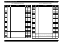
CONTENTS
Chapter 1 PRODUCT DESCRIPTION
1.1 FEATURES ....................................................................................................... 10
1.2 SPECIFICATIONS ..........................................................................................
1.2.1 Physical Specification ................................................................................
1.2.2 Printing Specification ................................................................................
1.2.3 Paper Feeding ............................................................................................
1.2.4 Input Data Buffer .......................................................................................
1.2.5 Electric Specification .................................................................................
1.2.6 Environmental Condition ...........................................................................
1.2.7 Reliability ..................................................................................................
1.2.8 Safety Approvals .......................................................................................
1.2.9 Acoustic Noise ...........................................................................................
1.2.10 CE Marking .............................................................................................
11
11
11
12
12
12
12
13
13
13
13
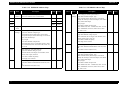
1.3 INTERFACE ..................................................................................................... 14
1.3.1 USB Interface ............................................................................................ 14
1.4 PCMCIA Card Slot ..........................................................................................
1.4.1 Card Slot Standard .....................................................................................
1.4.2 Supported Memory Card ...........................................................................
1.4.3 Supported Voltage .....................................................................................
15
15
15
15
1.5 Standalone Print Function ...............................................................................
1.5.1 File System ................................................................................................
1.5.2 File Format .................................................................................................
1.5.3 Valid Image Sizes ......................................................................................
1.5.4 Maximum Number of Photo Data Files .....................................................
1.5.5 Thumbnail Image Data ..............................................................................
1.5.6 File Sort .....................................................................................................
1.5.6.1 File Sort Rule .....................................................................................
1.5.6.2 Date Data Capture Rule .....................................................................
1.5.6.3 Date Range ........................................................................................
16
16
16
16
16
16
16
17
17
17
1.6 Printer PNL Operation Specifications ............................................................ 18
1.6.1 Switches ..................................................................................................... 18
1.6.2 Indicators ................................................................................................... 18
1.6.3 Panel Functions .......................................................................................... 18
1.6.4 Printer Condition and Panel Status ............................................................ 19
1.7 Printer Initialization ......................................................................................... 20
1.8 Initial setting values .......................................................................................... 20
1.9 Errors ................................................................................................................ 21
1.10 Printing of filled patterns ............................................................................... 21
1.11 Monochrome PNL operation specification ..................................................
1.11.1 Appearance ..............................................................................................
1.11.2 Swith Function .........................................................................................
1.11.3 Process LED ............................................................................................
1.11.4 Error Display (LCD) ................................................................................
22
22
23
23
23
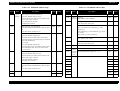
1.12 PAPER .............................................................................................................
1.12.1 Paper Handling ........................................................................................
1.12.2 Paper Specification ..................................................................................
1.12.2.1 Cut Sheet .........................................................................................
1.12.2.2 Envelope ..........................................................................................
1.12.2.3 EPSON special media .....................................................................
1.12.3 Printing Area ............................................................................................
1.12.3.1 Cut Sheet .........................................................................................
1.12.3.2 Envelopes ........................................................................................
24
24
24
24
24
24
26
26
27
1.13 INK CARTRIDGE ......................................................................................... 28
1.13.1 Black Ink Cartridge ................................................................................. 28
1.13.2 Color Ink Cartridge .................................................................................. 28
1.14 Accessories and Option .................................................................................. 29
1.15 Changing the Model Name ............................................................................ 29
Chapter 2 Operating Principles
2.1 Overview ............................................................................................................ 31
2.1.1 Printer Mechanism ..................................................................................... 31
Download Free Service Manual and Resetter Printer at http://printer1.blogspot.com
2.1.2 Printhead ....................................................................................................
2.1.2.1 Printing Process .................................................................................
2.1.2.2 Printing Method .................................................................................
2.1.3 Carriage Mechanism ..................................................................................
2.1.4 Paper Feeding Mechanism .........................................................................
2.1.5 Paper Loading Mechanism (ASF Unit) .....................................................
2.1.6 Ink System Mechanism ..............................................................................
2.1.6.1 Pump Unit & Wiper mechanism .......................................................
2.1.6.2 Capping Mechanism ..........................................................................
32
33
34
34
36
37
41
41
42
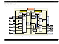
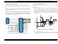
2.2 Electrical Circuit Operating Principles ..........................................................
2.2.1 C408 PSE board .........................................................................................
2.2.1.1 Process how 42VDC, 5VDC and 3.3VDC are generated .................
2.2.1.2 Protection circuit ...............................................................................
2.2.1.3 PS Control Function ..........................................................................
2.2.1.4 Power saving mode ...........................................................................
2.2.2 C408 MAIN Board ....................................................................................
2.2.2.1 Main elements ...................................................................................
2.2.2.2 Printhead Driver Circuit ....................................................................
2.2.2.3 CR Motor Driver Circuit ...................................................................
2.2.2.4 PF Motor Driver Circuit ....................................................................
2.2.2.5 ASF Motor Drive Circuit ..................................................................
2.2.2.6 Reset and EEPROM circuits .............................................................
2.2.2.7 Sensor Circuit ....................................................................................
43
43
44
45
45
45
46
48
49
50
50
51
51
52
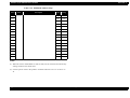
4.2.2.2 Monochrome panel board removal ................................................... 77
4.2.3 Housing Lower Cover Removal ................................................................ 78
4.2.3.1 Housing Lower Cover Left Removal ................................................ 78
4.2.3.2 Housing Lower Cover Right Removal .............................................. 79
4.2.4 Printhead removal ...................................................................................... 79
4.2.5 CR motor removal ..................................................................................... 82
4.2.6 Waste drain ink pad unit removal .............................................................. 83
4.2.7 Printer mechanism removal ....................................................................... 84
4.2.8 Circuit board removal ................................................................................ 85
4.2.9 LD Roller removal ..................................................................................... 88
4.2.10 HP/PE Sensor removal ............................................................................ 92
4.2.11 Ink system unit removal (Cap & Pump unit ) .......................................... 93
4.2.12 ASF Motor Removal ............................................................................... 97
4.2.13 Paper Eject Roller removal ...................................................................... 98
4.2.14 PF motor removal .................................................................................. 100
4.2.15 CR unit removal ..................................................................................... 102
4.2.16 Paper feed roller removal ...................................................................... 105
4.2.17 Disassembling ASF frame unit .............................................................. 108
4.3 Preview monitor disassembly procedure .....................................................
4.3.1 Back case removal ...................................................................................
4.3.2 Removal of the control board unit ...........................................................
4.3.3 Panel unit removal ...................................................................................
111
111
112
113
Chapter 5 Adjustment
Chapter 3 Troubleshooting
3.1 Overview ............................................................................................................ 54
5.1 Outline ............................................................................................................. 115
5.1.1 Adjustment items ..................................................................................... 115
3.2 Troubleshooting with LED Error Indications ............................................... 55
5.2 Parallel adjustor ............................................................................................. 116
Chapter 4 Disassembly and Assembly
4.1 Overview ............................................................................................................
4.1.1 Precautions .................................................................................................
4.1.2 Tools ..........................................................................................................
4.1.3 Work Completion Check ...........................................................................
68
68
70
71
4.2 Disassembly .......................................................................................................
4.2.1 Housing Removal ......................................................................................
4.2.2 Operation Panel removal ...........................................................................
4.2.2.1 Printer Panel Board Removal ............................................................
72
73
75
75
5.3 Adjustments with the service program ........................................................
5.3.1 Outline .....................................................................................................
5.3.2 Starting up the service program ...............................................................
5.3.3 EEPROM initial setting ...........................................................................
5.3.4 Head ID ....................................................................................................
5.3.5 Bi-D .........................................................................................................
5.3.6 USB ID ....................................................................................................
5.3.7 Memory card drive confirmation .............................................................
5.3.8 Head cleaning ..........................................................................................
5.3.9 Ink replenishment ....................................................................................
5.3.10 Refurbishment for DOA ........................................................................
118
118
118
120
121
122
123
124
124
125
126
Download Free Service Manual and Resetter Printer at http://printer1.blogspot.com
5.3.11 Protection counter ..................................................................................
5.3.12 Printing on normal A4 paper .................................................................
5.3.13 CSIC information ...................................................................................
5.3.14 EEPROM data .......................................................................................
127
128
129
130
5.4 Firmware update ............................................................................................ 131
5.4.1 Firmware update method ......................................................................... 131
5.4.2 Firmware version check method .............................................................. 132
5.5 Adjustment/inspection of the preview monitor ...........................................
5.5.1 Update to the firmware for inspection .....................................................
5.5.2 Brightness adjustment ..............................................................................
5.5.2.1 Brightness adjustment procedures ...................................................
5.5.3 Image pattern inspection ..........................................................................
133
133
134
134
135
Chapter 6 Maintenance
6.1 Overview .......................................................................................................... 137
6.1.1 Cleaning ................................................................................................... 137
6.1.2 Service Maintenance ................................................................................ 138
Chapter 7 Appendix
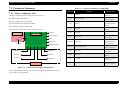
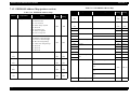
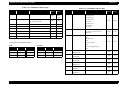
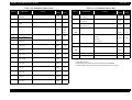
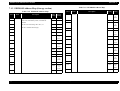
7.1 Connector Summary ......................................................................................
7.1.1 Major Component Unit ............................................................................
7.1.2 EEPROM Address Map (printer section) ................................................
7.1.3 EEPROM Address Map (Storage section) ..............................................
146
146
151
154
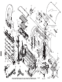
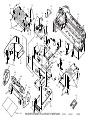
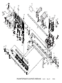
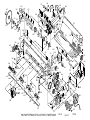
7.2 Exploded Diagram .......................................................................................... 159
7.3 Parts List ......................................................................................................... 165
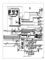
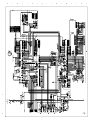
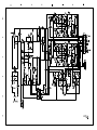
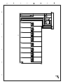
7.4 Electrical Circuits ........................................................................................... 169
Download Free Service Manual and Resetter Printer at http://printer1.blogspot.com
CHAPTER
1
PRODUCT DESCRIPTION
Download Free Service Manual and Resetter Printer at http://printer1.blogspot.com
EPSON Stylus PHOTO 895/785EPX
Revision A
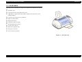
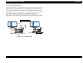
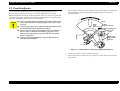
1.1 FEATURES
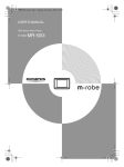
The major features of EPSON color inkjet printer EPSON Stylus PHOTO 895/785EPX
are:
Standalone print
Card reader function for PCMCIA Flash ATA
Applicable to Compact Flash, Smart Media, Memory Stick, Microdrive (with
PCMCIA adapter)
Connected with a printer unit via USB hub
High Color Print Quality
High Speed Printing
Exclusively used for USB I/F
Windows/Macintosh exclusive
Compact, Space Saving
Multi-size Compatible ASF
Roll paper can be used
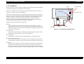
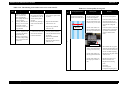
Preview monitor (optional)
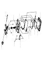
Figure 1-1. External View
PRODUCT DESCRIPTION
FEATURES
10
EPSON Stylus PHOTO 895/785EPX
Revision A
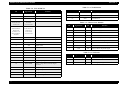
1.2 SPECIFICATIONS
Table 1-2. Raster Graphics Mode
Horizontal
Resolution
Printable Area
Available Dot
CR Speed
1.2.1 Physical Specification
360 dpi
8.26 inches
2976
23.8 IPS
Weight:
720 dpi
8.26 inches
5952
20 IPS
1440 dpi
8.26 inches
11904
20 IPS
This section covers specifications of the printer.
5.25kg (without ink cartridges)
Dimension:
Storage:
Printing:
467 mm (W) x 255.7 mm (D) x 212.1mm (H)
467 mm (W) x 484.1mm (D) x 308.5mm (H)
Control Code
ESC/P Raster
Character Tables
1.2.2 Printing Specification
One international character sets:
Print Method
- PC 437 (US, Standard Europe)
On demand ink jet
Typeface
Nozzle Configuration
Bit map LQ font:
Monochrome 48 nozzles
Color 48 nozzles x 5 (Cyan, Magenta, Yellow, Light cyan, Light magenta)
EPSON Courier 10 CPI
Print Direction
Bi-direction with logic seeking
Print Speed & Printable Columns
Table 1-1. Character Mode
Character Pitch
Printable Column
LQ Speed
10 CPI (Pica)
82
238 CPS*
*This value is the speed of normal-dot printing.
PRODUCT DESCRIPTION
SPECIFICATIONS
11
EPSON Stylus PHOTO 895/785EPX
Revision A
[220 ~ 240V Version]
Rated Voltage:
Input Voltage Range:
Rated Frequency Range:
Input Frequency Range:
Rated Current:
Power Consumption:
1.2.3 Paper Feeding
Feed Method
Friction feed with ASF
Paper Path
Cut-sheet ASF
AC220V~240V
AC198~264V
50~60Hz
49.5~60.5Hz
0.25 A
Approx. 19W (ISO10561 Letter Pattern)
Approx. 3.5W in standby mode
Energy Star compliant
10M ohms min.
(between AC line and chassis, DC 500V)
AC 1500V rms. 1 minute
(between AC line and chassis)
(Top entry, Front out)
Feed Speed
Insulation Resistance:
126 ms (during 10.16 mm paper feed)
Dielectric Strength:
114.3mm/sec (Fast, Continuous feed)
1.2.4 Input Data Buffer
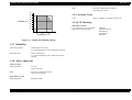
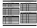
1.2.6 Environmental Condition
32KB
Temperature
1.2.5 Electric Specification
[120V Version]
Rated Voltage:
Input Voltage Range:
Rated Frequency Range:
Input Frequency Range:
Rated Current:
Power Consumption:
Insulation Resistance:
Dielectric Strength:
PRODUCT DESCRIPTION
AC120V
AC90~132V
50~ 60Hz
49.5~ 60.5Hz
0.45A
Approx. 19W (ISO10561 Letter Pattern)
Approx. 3.5W in standby mode
Energy Star compliant
10M ohms min.
(between AC line and chassis, DC 500V)
AC 1000V rms. 1 minute or
AC 1200V rms. 1 second
(between AC line and chassis)
Operating:
10 to 35×C (see the figure below for condition)
Non-operating:
-20 to 60×C (with shipment container)
1 month at 40×C and 120 hours at 60×C
Humidity
Operating:
20 to 80% RH
(without condensation / see the figure below for
condition)
Non-operating:
5 to 85% RH
(without condensation / with shipment container)
Resistance to Shock
Operating:
1G, within 1 ms
Non-operating:
2G, within 2 ms (with shipment container)
Resistance to Vibration
Operating:
0.15G
Non-operating:
0.50G (with shipment container
SPECIFICATIONS
12
EPSON Stylus PHOTO 895/785EPX
Revision A
EMI:
90
EN55022 (CISPR Pub.22) Class B
AS/NZS 3548 Class B
1.2.9 Acoustic Noise
80
70
Level:
Approx. 47dB(A) (According to ISO 7779)
60
Humidity (%)
50
1.2.10 CE Marking
40
[220~240V Version]
Low Voltage Directive 73/23/EEC:
EMC Directive 89/336/EEC:
30
20
10
20
27 30
35
40
Temperature (°C)
EN60950
EN55022 Class B
EN61000-3-2
EN61000-3-3
EN55024
Figure 1-2. Temperature/Humidity Range
1.2.7 Reliability
Total Print Volume:
16,000 pages (A4, Letter)
or 5 years although less than 50.000 pages printing
Print Head Life:
3 billion dots/nozzle
or 5 years although less than 3 billion dots/nozzle
printing
1.2.8 Safety Approvals
[120V Version]
Safety Standards:
EMI:
[220~240V Version]
Safety Standards:
UL1950
CSA22.2 No.950
FCC part 15 subpart B Class B
CSA C108.8 Class B
EN60950 (VDE)
PRODUCT DESCRIPTION
SPECIFICATIONS
13
EPSON Stylus PHOTO 895/785EPX
Revision A
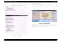
Device ID
1.3 INTERFACE
[00H] [60H]
MFG: EPSON;
CMD: ESCPL2, BDC, D4;
MDL: Stylus [SP] Photo [SP] 785 EPX;
CLS: PRINTER;
DES: EPSON [SP]Stylus [SP] Photo [SP] 785EPX;
The EPSON Stylus PHOTO 895/785EPX provides USB and as standard.
1.3.1 USB Interface
Standard:
Based on:
“Universal Serial Bus Specification Rev. 1.1”
“Universal Serial Bus Device Class Definition
for Printing Device Version 1.1” (Printer)
“Universal Serial Bus Mass Storage Class
Bulk-Only Transport Rev. 1.0” (Storage)
12Mbps (Full Speed Device)
NRZI
USB Series B
2 meters
Bit Rate:
Data Encoding:
Adaptable Connector:
Recommended Cable Length:
Table 1-3. Connector Pin Assignment and Signals
Pin No.
Signal Name
I/O
Function Description
1
VCC
-
Cable power. Max. power consumption is 2mA.
2
-Data
Bi-D
Data
3
+Data
Bi-D
Data, pull up to +3.3 V via 1.5K ohm resistor.
4
Ground
-
Cable ground
Pin #2
Pin #1
Pin #3
Pin #4
Figure 1-3. USB Pin Assignment
PRODUCT DESCRIPTION
INTERFACE
14
EPSON Stylus PHOTO 895/785EPX
Revision A
1.4 PCMCIA Card Slot
1.4.1 Card Slot Standard
PCMCIA Type-II card slot x 1
(In accordance with the PC Card Standard (‘97), JEIDA)
1.4.2 Supported Memory Card
•PCMCIA Flash ATA card
•Compact Flash (with PCMCIA adapter)
•Smart Media (with PCMCIA adapter)
•Memory Stick (with PCMCIA adapter)
•Microdrive (with PCMCIA adapter)
1.4.3 Supported Voltage
•5v only
•3.3v/5v
•3.3v only
Note1: Media that uses 3.3v/5v is automatically set based on the VS1 terminal
(PCMCIA).
Note2: The supply current to the memory card is max. 330mA.
PRODUCT DESCRIPTION
PCMCIA Card Slot
15
EPSON Stylus PHOTO 895/785EPX
Revision A
1.5 Standalone Print Function
1.5.3 Valid Image Sizes
The image sizes that are valid in this machine are in accordance with DCF Version 1.0.
1.5.1 File System
Note that the image sizes that are mandatory for DCF Version 1.0 are as follows:
The file system that can be used by the standalone print function of this machine is
DCF Version 1.0 only.
Compatibility of other file systems is not guaranteed.
Also, the file system that the card reader function can handle is in accordance with the
specifications of the host.
For the detailed specification of DCF, see “Camera File System Standard DCF Version
1.0, JEIDA-49-2-1998”.
160 <= Y <= 1200 (pixel)
However, this machine handles the following size range:
Horizontal: 160 <= X <= 3200 (pixel)
Vertical:
160 <= Y <= 3200 (pixel)
This machine can handle up to 999 photo data files. If 1000 or more photo data files are
recorded in a memory card, these files are sorted in accordance with the file sort rule of
this machine, and photo data with photo numbers 1 to 999 are used as valid data. Photo
data files that are specified for printing in the camera specification file can be specified
for printing only if their photo number exceed 999. However, the numbers of photos
that can be specified for printing are limited to 999.
The following file formats can be used for this machine:
JPEG file (*.JPG)
Photo data file in accordance with Exif Version 2.1
UDL file (*.USD)
Definition file for user defined layout. Only files in the ¥MISC¥ directory are
valid.
Camera specification file (*.MRK)
Definition file used in camera specification mode. “AUTOPRINT.MRK” file that
has a full-pass name with up to 32 characters is valid.
EPSON frame file (*.EFF)
1.5.5 Thumbnail Image Data
Only thumbnail image data in accordance with DCF Version 1.0 (160x120 pixels in
Exif format) can be handled. This machine uses thumbnail images in index print mode.
However, you can set not to use thumbnail images in this mode.
1.5.6 File Sort
Frame data file format defined for standard use of EPSON products. Only files in
the “¥MISC¥FRAME¥” directory are valid.
PRODUCT DESCRIPTION
Vertical:
1.5.4 Maximum Number of Photo Data Files
1.5.2 File Format
* PNG and TIFF formats are not supported.
Horizontal: 160 <= X <= 1800 (pixel)
This machine sorts all the photo data files in a memory card using the information such
as date, time, and file name attached to the photo data files to assign photo numbers.
Because the photo number is assigned in accordance with the file sort rule specific to
this machine, it may not match with the photo number displayed when the data is
viewed in a digital camera.
Standalone Print Function
16
EPSON Stylus PHOTO 895/785EPX
Revision A
1.5.6.1 File Sort Rule
This machine sorts the photo data files based on the following priorities:
1.
Older data first. The date and time information attached to the photo data files are
used for sorting. Up to seconds are used for the time information.
2.
If files with same date exist, the full-pass of the file names are sorted in normal
ASCII order.
1.5.6.2 Date Data Capture Rule
This machine tries to capture the date and time from each photo data file based on the
following priorities:
1.
Date and time information in accordance with the digital camera standard format
(Exif).
2.
Data and time information of the file system supported in DOS (timestamp of the
file).
3.
Fixed values (1 January 1970 00:00:00)
Note that the date and time information attached to each photo data file may not match
with the date and time at which the photo was captured. Some of the said date and time
data is updated due to a calendar setting (whether the function exist/not exist, incorrect
preset date) in a digital camera, post-processing or restoring of the photo data. If the
data has been updated, this machine captures the updated date and time information for
further processing.
1.5.6.3 Date Range
This machine can handle the following range of date. If photo data files have date and
time information outside the following range, all the file sort results are undetermined.
1 January 1970 00:00:00 - 31 December 2069 23:59:59
PRODUCT DESCRIPTION
Standalone Print Function
17
EPSON Stylus PHOTO 895/785EPX
Revision A
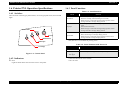
1.6 Printer PNL Operation Specifications
1.6.3 Panel Functions
Table 1-4. Panel Functions
1.6.1 Switches
Switch
Function
There are three non-lock type push switches, one lock-type push switch, and one LED
lights.
Maintenance
• Loads or Ejects the Paper (Pushing within 3seconds).
• Starts the Cleaning of head (Pushing for 3seconds).
• When carriage is on the Ink Cartridge change position, return
carriage from Ink Cartridge change position.
Roll paper
• Loads or Ejects (Back Out feed by pushing for 3 seconds) the Roll
paper.
• Tear Off feed and return.
• When carriage is on the Ink Cartridge change position, return
carriage from Ink Cartridge change position.
Replacement
• Starts the Ink Cartridge change sequence.*
• Moves the carriage to cartridge change position.
• When carriage is on the Ink carriage change position, return
carriage from Ink cartridge change position.
Error LED
Power
Maintenance
Roll Paper
*This function is not available in printing status.
Table 1-5. Panel Functions with Power On
Cartridge
Figure 1-4. Control Panel
Switch
Function
Maintenance
• Start status printings.
Maintenance
+
Roll paper
• Enters the special setting mode (Factory use only). *2
1.6.2 Indicators
*1 Not described in the user's manual.
Error
*2 See the table
Lights or blinks when some error has occur to the printer
PRODUCT DESCRIPTION
Printer PNL Operation Specifications
18
EPSON Stylus PHOTO 895/785EPX
Revision A
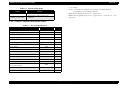
"-": No change.
"A->B": A is a indicator condition when carriage is on Home Position
B is indicator in ink exchange sequence.
.
Table 1-6. Special Setting Mode
Switch
Function
• Initialize EEPROM.
Maintenance
Roll paper
(Pushing for 10 seconds)
•Blink: Repeats lighting on for 0.5 sec.+ off for 0.5 sec.
•Blink2: Repeats lighting on for 0.2 sec.+ off for 0.2 sec. + on for 0.2 sec.+ off
for0.4 sec.
• Reset the ink overflow counter in the
EEPROM.
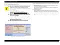
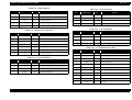
1.6.4 Printer Condition and Panel Status
Table 1-7. Error LED Indication
Printer Status
Error LED
Priority
Power ON
-
10
Ink sequence proceeding
-
6
Ink cartridge changing
-
5
Data processing
-
9
Paper out
On
4
Paper jam condition
On
3
Ink end (black)
On -> Blink
8
Ink low (black)
Blink
8
Ink end (color)
On -> Blink2
9
Ink low (color)
Blink
8
On -> On
8
On
7
Reset, Timer IC reset, EEPROM clear
On (1s)
-
Ink overflow counter reset
On (2s)
-
Blink
2
On
1
Blink2
-
Ink end (both color, black)
No ink cartridge (color or black)
Maintenance request
(Ink overflow counter)
Fatal error
Special setting
PRODUCT DESCRIPTION
Printer PNL Operation Specifications
19
EPSON Stylus PHOTO 895/785EPX
Revision A
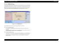
1.7 Printer Initialization
1.8 Initial setting values
There are three kinds of initialization methods, and the following explains each
initialization.
Initial setting values during the initial operation are as follows. For the storable items
of panel setting, default setting and remote commands, the memory contents become
default values.
1.
Power-on Initialization
This is the initializing operation when the printer power is turned on.
When printer is initialized, the following actions are performed:
(a) Initializes printer mechanism.
(b) Clears input data buffer.
(c) Clears print buffer.
(d) Sets default values.
2.
Operator Initialization
This printer is initialized when turning the printer power on again within 10
seconds from last power off.
Page position:
Current paper position shall be the page front end position.
Line feed:
4.23 mm (1/6 inch)
Right margin:
80 columns
Left margin:
1st column
Character pitch:
10CPI
Print mode:
Text mode (Non-raster graphic mode)
When printer is initialized, the following actions are performed:
(a) Cap the printer head.
(b) Eject a paper.
(c) Clears input data buffer.
(d) Clears print buffer.
(e) Sets default values.
3.
Software Initialization
The ESC@ command also initialize the printer.
When printer is initialized, the following actions are performed:
(a) Clears print buffer.
(b) Sets default values.
PRODUCT DESCRIPTION
Printer Initialization
20
EPSON Stylus PHOTO 895/785EPX
Revision A
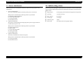
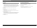
1.9 Errors
1.10 Printing of filled patterns
Ink Out
Filled patterns can be printed by the following methods.
When the printer runs out most of the ink of any color, it indicates ink-low and
keeps printing. When the printer runs out the whole ink of any color, it stops
printing and indicates ink-out error. User is then requested to install a new inkcartridge in this state. An ink-cartridge that has been taken out once should never
be used again. Re-installation of the cartridge not filled fully upsets the ink level
detection and may eventually cause a serious problem in the print head.
Printing by Remote Command
Use the NC command from the remote commands.
Status Printing
Turn the power on while pressing the Paper Feed / Eject button.
Print by the D4 Control Command
Paper Out
Send the NC command by the C4 command channel.
When the printer fails to load a sheet, it goes into a paper out error.
Paper Jam
When the printer fails to eject a sheet, it goes into a paper jam error.
No Ink-Cartridge
When the printer detects that ink-cartridge comes off, or failed to read or write
CSIC data, it goes into this error mode.
Maintenance Request
When the total amount of ink wasted through cleanings and flushing reaches to the
limit, printer indicates this error and stops. In such a case, the absorber in the
printer enclosure needs to be replaced with new one by service personnel.
Fatal Errors
Carriage control error.
PRODUCT DESCRIPTION
Errors
21
EPSON Stylus PHOTO 895/785EPX
Revision A
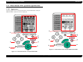
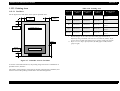
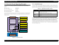
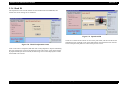
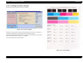
1.11 Monochrome PNL operation specification
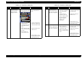
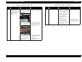
1.11.1 Appearance
Following figures show the monochrome PNLs of Stylus PHOTO895 and Stylus
PHOTO785EPX. (When all LCDs are displayed)
Print Mode
Print Mode
Paper Type
Paper Type
Paper Size
Paper Size
Page Layout
Page Layout
Select Photo
Select Photo
Copies
Copies
Quality
Photo enhance
Quality
Photo enhance
c
c
Select Photo
Select Photo
Brightness
Brightness
h
f
h
f
Cancel
int
Pr
g
int
Pr
g
Cancel
e
Processing
Processing
e
d
i
d
i
Figure 1-6. Monochrome PNL of Stylus PHOTO785 EPX
Figure 1-5. Monochrome PNL of Stylus PHOTO895
PRODUCT DESCRIPTION
Monochrome PNL operation specification
22
EPSON Stylus PHOTO 895/785EPX
Revision A
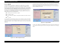
1.11.2 Swith Function
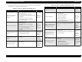
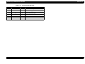
1.11.4 Error Display (LCD)
This machine displays the following errors with numbers (blinking) on the LCD panel.
Table 1-8. Switch description
No.
Name
Description
Table 1-9. Error LCD Indication
1
LCD PNL
Indicates the print condition setting contents of printer
2
Print
Printer start operation
3
Cancel
Cancellation of operations and printing action
4
Select Photo
Selects one or all frames
5
Cross-shaped key
Moves the cursor.
6
Brightness
Sets frame function.
7
Processing
Lights on or blinks while processing.
Display
(First
line)
Display
(Second
line)
Remarks
No ink (black)
Err
IEb
-
No ink (color)
Err
IEc
No paper
Err
PE
-
Paper jam
Err
PJ
-
No ink
cartridge/abnormality
Err
IC
-
Maintenance required
Err
Sr
-
Source
Printer
1.11.3 Process LED
Detail of error
This LED turns on while the power of the main unit is on and blinks during data
processing.
Printon
Memory card error
Err
CE
When an error occurred
during reading data from a
memory card
Data processing means the following states:
Common
Fatal error
Err
FE
Unrecoverable error
²
Print data exist
²
Performing ink sequence
²
Changing ink cartridge
²
Accessing to a memory card
²
Performing standalone printing
Do not remove the memory card while this LED blinks.
PRODUCT DESCRIPTION
Monochrome PNL operation specification
23
EPSON Stylus PHOTO 895/785EPX
Revision A
1.12 PAPER
Japanese Chokei4
Japanese Yokei1
Japanese Yokei2
Japanese Yokei3
Japanese Yokei4
1.12.1 Paper Handling
(90mm x 205mm)
(120mm x 176mm)
(114mm x 162mm)
(98mm x 148mm)
(105mm x 235mm)
Do not perform reverse feed more than 1.8mm (0.07”).
[Quality]
1.12.2 Paper Specification
#10•DL•C6:
Japanese Chokei3,4:
Japanese Yokei1,2,3,4:
1.12.2.1 Cut Sheet
[Size]
A4:
A5:
A6:
B5:
Letter:
Half Letter:
Legal:
Executive:
Bond paper, PPC, Air mail
Craft, New Kent
Craft, New Kent
[Weight]
(210mm x 297mm)
(148mm x 210mm)
(105mm x 148mm)
(182mm x 257mm)
(216mm x 279mm)
(139.7mm x 215.9mm)
(216mm x 356mm)
(184.2mm x 266.7mm)
[Quality]
#10•DL•C6:
45g/m2 ~ 75g/m2 (12 lb ~ 20 lb)
Japanese Chokei3,4:
50g/m2 ~ 70g/m2 (43 kg ~ 60 kg)
Japanese Yokei1,2,3,4:
50g/m2 ~ 100g/m2 (43 kg ~ 86 kg)
* Envelope printing is only available at normal temperature.
* Keep the longer side of the envelope horizontally at setting.
1.12.2.3 EPSON special media
[Quality]
Plain paper, Bond paper
[Thickness]
EPSON specifically designed media for ink jet printers
(1) Photo Quality Ink Jet Paper
0.08mm ~ 0.11mm (0.003 ~ 0.004 inch)
[Size]
[Weight]
A4:
A6:
B5:
Letter:
Legal:
5” x 8”:
8” x 10”:
Japanese Postcard:
64g/m2 ~ 90g/m2 (17 lb ~ 24 lb, 55kg ~ 78kg)
1.12.2.2 Envelope
[Size]
#10
DL
C6
220x132
Japanese Chokei3
(241.3mm x 104.8mm)
(220mm x 110mm)
(162mm x 114mm)
(220mm x 132mm)
(120mm x 205mm)
PRODUCT DESCRIPTION
PAPER
(210mm x 297mm)
(105mm x 148mm)
(182mm x 257mm)
(216mm x 279mm)
(216mm x 356mm)
(127mm x 203mm)
(203mm x 254mm)
(100mm x 148mm)
24
EPSON Stylus PHOTO 895/785EPX
Revision A
[Size]
(2) 360dpi Ink Jet Paper
A4:
Letter:
[Size]
A4:
Letter:
(210mm x 297mm)
(216mm x 279mm)
(210mm x 297mm)
(216mm x 279mm)
(3) Ink Jet Transparencies
[Size]
A4:
Letter:
A6:
(210mm x 297mm)
(216mm x 279mm)
(105mm x 148mm)
(4) Photo Quality Glossy Film
[Size]
A4:
Letter:
Japanese Postcard:
(210mm x 297mm)
(216mm x 279mm)
(100mm x 148mm)
(5) OHP Sheet
[Size]
A4:
Letter
(210mm x 297mm)
(216mm x 279mm)
(6) Matte Paper
[Size]
A4:
Letter:
(210mm x 297mm)
(216mm x 279mm)
(7) Label Sheet
[Size]
A4:
Japanese Postcard:
A6:
(210mm x 297mm)
(100mm x 148mm)
(105mm x 148mm)
(8) Iron-On Cool Peel Transfer Paper
PRODUCT DESCRIPTION
PAPER
25
EPSON Stylus PHOTO 895/785EPX
Revision A
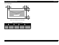
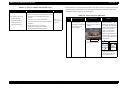
1.12.3 Printing Area
Table 1-10. Printing Area
1.12.3.1 Cut Sheet
Paper Size
Left Margin
(min.)
Right Margin
(min.)
Top Margin
(min.)
See the figure below and tables on the right for printable areas.
Left Margin
3mm
Top Margin
3mm
Bottom Margin
(min.)
A4
3 mm (0.12”)
3 mm (0.12”)
3 mm (0.12”)
14 mm (0.54”) / 3mm
(0.12”) *
Letter
3 mm (0.12”)
3 mm (0.12”)
3 mm (0.12”)
14 mm (0.54”) / 3mm
(0.12”) *
B5
3 mm (0.12”)
3 mm (0.12”)
3 mm (0.12”)
14 mm (0.54”) / 3mm
(0.12”) *
Legal
3 mm (0.12”)
3 mm (0.12”)
3 mm (0.12”)
14 mm (0.54”) / 3mm
(0.12”) *
Executive 3 mm (0.12”)
3 mm (0.12”)
3 mm (0.12”)
14 mm (0.54”) / 3mm
(0.12”) *
Right Margin
3mm
Printable Area A
*
Bottom margin can be reduced to 3mm when paper dimension is
defined by using command, otherwise it is not reduced (14mm). As for
an area between 3mm and 14mm margin, printing quality may decline.
** Refer to 1.12.2 "Paper Specification" for PW (paper width) and PL
(paper length).
14mm
Bottom
Margin 3mm
Printable Area B
Printable Area A
Figure 1-7. Printable Area for Cut Sheet
As shown in the illustration above, the printing range consists of a combination of
printable areas A, B and C.
The quality of the printing in each of the A, B and C printing areas is different, and
there are cases where printing in the B and C areas becomes garbled.
PRODUCT DESCRIPTION
PAPER
26
EPSON Stylus PHOTO 895/785EPX
Revision A
1.12.3.2 Envelopes
LM
RM
TM
Printable Area
BM
Figure 1-8. Printable Area for Envelopes
Table 1-11. Envelope Margin
Size
Left Margin
(min.)
Right Margin
(min.)
Top Margin
(min.)
Bottom Margin
(min.)
#10
3 mm (0.12”)
28 mm (1.10”)
3 mm (0.12”)
14 mm (0.55”)
DL
3 mm (0.12”)
7 mm (0.28”)
3 mm (0.12”)
14 mm (0.55”)
C6
3 mm (0.12”)
3 mm (0.12”)
3 mm (0.12”)
14 mm (0.55”)
PRODUCT DESCRIPTION
PAPER
27
EPSON Stylus PHOTO 895/785EPX
1.13 INK CARTRIDGE
1.13.1 Black Ink Cartridge
Type:
Color:
Print Capacity:
Ink Life:
Storage Temperature:
Storage:
Packing:
Transit:
Dimension:
Weight:
Exclusive Cartridge
Black
540 pages/A4
(ISO/IEC 10561 Letter Pattern at 360 dpi)
2 years from date of production
-20 oC to 40 oC (within a month at 40 oC)
-30 oC to 40 oC (within a month at 40 oC)
-30 oC to 60 oC (within 120 hours at 60 oC
and within a month at 40 oC)
20.1 mm (W) x 66.85 mm (D) x 38.5 mm (H)
37 g
Revision A
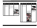
1.13.2 Color Ink Cartridge
Type:
Color:
Print Capacity:
Ink Life:
Storage Temperature:
Storage:
Packing:
Transit:
Dimension:
Weight:
Exclusive Cartridge
Magenta, Cyan, Yellow, Light Cyan, Light Magenta
220 pages / A4 (360 dpi, 5% duty each color)
2 years from date of production
-20 oC to 40 oC (within a month at 40 oC)
-30 oC to 40 oC (within a month at 40 oC)
-30 oC to 60 oC (within 120 hours at 60 oC
and within a month at 40 oC)
49.1 mm (W) x 66.85 mm (D) x 38.5 mm (H)
88 g
Figure 1-10. Color Ink Cartridge
Note 1: Ink cartridge can not be refilled. The ink cartridge is prepared only
for article of consumption.
Note 2: Do not use the ink cartridge which contains life-expired ink.
Note 3: Ink will be frozen under -18~-21oC environment; however, it will be
usable after placing it more than 3 hours at room temperature.
Figure 1-9. Black Ink Cartridge
PRODUCT DESCRIPTION
INK CARTRIDGE
28
EPSON Stylus PHOTO 895/785EPX
Revision A
1.14 Accessories and Option
1.15 Changing the Model Name
Standard accessories
By setting the proper values in addresses 5EH and 60H to 7DH in EEPROM, the
Device ID and the model name in the BDC-ID can be changed. The other fields other
than the model name are fixed and cannot be changed.
²
Instruction manual
²
Ink cartridge (black, color)
²
CD-ROM (Printer driver, utility)
²
Roll paper holder
Table 1-12. Setting the Model Name
EEPROM setting
Option
²
MDL value for Device
ID and BDC-ID
60H~7DH
00H
don't care
[00H]
[4EH (51H)]
MDL:
Stylus Photo 895;
Japanese
01H
Standard Device
don't care
[00H]
[46H (49H)]
MDL:
PM-790PT;
Preview monitor
World Standard
Device
(Euro, Asia)
Custom
02H
<Model Name
String)
World Standard
Device (US)
03H
don't care
*
PRODUCT DESCRIPTION
Device ID
bytes counter
5EH
[00H]
MDL:
[37H(4AH)+nnx2]* <Model Name String>
[00H]
[51H (54H)]
MDL:
Stylus Photo 785EPX;
The values parenthesis are used when IEEE 1284.4 is valid. [nn] indicates the
number of bytes in <Model Name String> stored in E2H-FFH. “ 00H” should
be place at the end of the model name string.
Accessories and Option
29
CHAPTER
2
OPERATING PRINCIPLES
Download Free Service Manual and Resetter Printer at http://printer1.blogspot.com
EPSON Stylus PHOTO 895/785EPX
Revision A
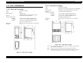
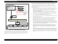
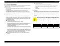
2.1 Overview
Paper Eject Roller
This section describes the operating principles of the printer mechanism and electrical
circuit boards. The Stylus PHOTO 895/785EPX has the following boards:
Main board:
C408 MAIN
Power supply board:
C408 PSB/PSE
PF Motor
PF Roller
CR Timing Belt
Star Wheel Roller
Monochrome panel board: C408 PNL
Printer panel board:
C408 PNL-B
2.1.1 Printer Mechanism
HP Sensor
CR Unit
The printer mechanism for Stylus PHOTO 895/785EPX is designed newly. But, the
basic component of the printer mechanism is same as previous product.
This printer consists of Print Head, Carriage Mechanism, Paper Feeding Mechanism,
Paper Loading Mechanism, Ink System (Pump Mechanism, Cap Mechanism, and
Carriage Lock Mechanism).
PE Sensor
LD Roller
Paper Feed Back Plate
Like other EPSON ink jet printers, the Stylus PHOTO 895/785EPX is equipped with
three stepping motors; one for ASF/Pump mechanism, one for Paper feeding
mechanism and one for carriage mechanism. ASF unit uses rear entry front eject
system. This ASF unit is also designed so that the single LD roller loads the paper to
the printer mechanism. For cap assembly, Stylus PHOTO 895/785EPX uses valveless
mechanism.
Paper Separation Pad
ASF Hopper Spring
CR Lock Lever
Clutch Mechanism
ASF Motor
Pump Assembly
Cap Assembly
CR Motor
Figure 2-1. Printer Mechanism Block Diagram
Operating Principles
Overview
31
EPSON Stylus PHOTO 895/785EPX
Revision A
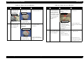
2.1.2 Printhead
CSIC
Nozzle Selector Board
The printhead uses a new developed U-CHIPS head and Stylus PHOTO 895/785EPX
can perform multiple shot printing and variable printing.
The CSIC is mounted on the ink cartridge. By storing ink life data, this IC makes it
possible to control the ink in ink cartridge unit.
Ink Cartridge
CSIC Connection Circuit
Needle
The basic operating principles of the printhead, which plays a major role in printing,
are the same as previous models; on-demand method which uses PZT (Piezo Electric
Element). In order to uniform the amount of ejecting ink, the printhead has its own
head ID (13 digits for this printhead) which adjust PZT voltage drive features.
The printhead stores the head ID to EEPROM and generates appropriate PZT drive
voltage to prevent amount of ink from varying by printheads.
Following explains printhead basic components.
Filter
PZT
PZT is an abbreviation of Piezo Electric Element. Certain amount of voltage
expands and contracts PTZ. The drive wave generated on MAIN board drives PZT
and PZT pushes the top cavity which has ink stored to discharge the ink from each
nozzle on the nozzle plate.
Nozzle Plate
PZT
Cavity
Figure 2-2. Printhead Sectional Drawing
Ink Cavity
The ink absorbed from the ink cartridge goes through the filter and then is stored
temporarily in this tank called “cavity” until PZT is driven.
Nozzle Plate
The board with nozzle holes on the printhead surface is called Nozzle Plate.
CSIC Connection Circuit
This circuit connects the CSIC mounted on the ink cartridge and the main board.
One end of the wire harness connects with the print head cable to the main board.
Filter
When the ink cartridge is installed, if any dirt or dust around the cartridge needle is
absorbed into the head, there is a great possibility of causing nozzle clog and
disturbance of ink flow, and finally causing alignment failure and dot missing. To
prevent this problem, a filter is set below the cartridge needle, where ink is filtered.
Operating Principles
Overview
32
EPSON Stylus PHOTO 895/785EPX
Revision A
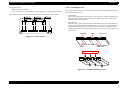
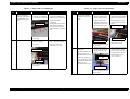
Nozzle Layout
2.1.2.1 Printing Process
Black: 48 nozzles (120 dpi)
Color: 48 nozzles x5(Cyan, Magenta, Yellow, Light cyan, Light magenta)(120dpi)
The nozzle layout when viewed from the back surface of the head is shown below.
This section explains the process in which the printheads of On-Demand inkjet printers
eject ink from each nozzle.
1.
Normal State:
When no printing signal is sent from PC, or no PZT drive voltage is applied, PZT
does not change shape, therefore PZT does not squeeze the cavity. Ink pressure
inside the cavity is kept normal.
2.
Ejecting State:
When the print signal is output from the C408 MAIN board, IC (Nozzle Selector)
located on the printhead unit latches data once by 1-byte unit. An appropriate PZT
latched by the nozzle selector is pushed into the cavity by the common voltage
applied from the main board. By this operation, ink stored in the cavity spurts out
from nozzles.
Ink Path
PZT
Ink Cavity
Figure 2-3. Nozzle Layout
Nozzle plate
Nozzle
PZT drive voltage
Figure 2-4. Printhead Printing Process
Operating Principles
Overview
33
EPSON Stylus PHOTO 895/785EPX
Revision A
2.1.2.2 Printing Method
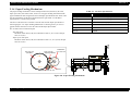
2.1.3 Carriage Mechanism
For print dot system, Stylus PHOTO 895/785EPX has the following two kinds of
printing modes.
The carriage mechanism consists of Carriage motor (CR motor), Carriage unit
(including printhead), CR timing belt, CR guide shaft, platen gap adjustment
mechanism, parallelism adjustment mechanism CR guide frame, CR home detector
(HP/PE sensor) etc. The carriage mechanism moves the carriage back and forth
according to the drive from the carriage motor. The following stepping motor is
mounted to drive CR mechanism. (See the table below.)
Multiple shot printing
Variable dot printing
The above two printing modes are automatically selected depending on the media and
the resolution setting of the printer driver. The following explains each printing mode.
Table 2-1. Carriage Motor Specification
Multiple shot printing
Items
This printing mode is developed to improve the print quality on plain paper or
transparencies in low resolution. The multiple shot printing mode uses normal dot
and the number of dot shots varies from 1 shot to maximum 3 shots depending on
the print data to enable sharp image output even in a low resolution.
Variable dot printing
This printing mode is developed to improve the print quality on exclusive paper.
This mode is basically the same as variable dot printing mode used on other
products ; micro dot, middle dot, and large dot compose this mode. Print dot size
varies according to print data and this mode enables even sharper image output on
exclusive paper.
Specifications
Type
4-Phase/ 200-Pole HB Stepping motor
Drive Voltage
+42 V +/ - 5% (DRV IC voltage)
Coil Resistance
7.8 Ω +/ - 10% (per phase at 25 degree)
Inductance
14 mH +/ - 20%(1KH 1VmA)
Drive Method
Bi-Polar drive
Driver IC
LB1946
The drive from CR motor is transferred to the CR unit via CR timing belt. And the CR
home position is detected with the HP sensor. This sensor is available as CR HP
detector only in the HP (home position) detection sequence & pump operation
sequence.
Operating Principles
Overview
34
EPSON Stylus PHOTO 895/785EPX
Revision A
HP Sensor
CR Motor
Adjust Lever
Parallelism Adjustment Bushing
CR Unit
Carriage Guide Shaft
CR Guide Shaft
CR Timing Belt
Adjust Lever
Eccentric Shaft
Figure 2-5. Carriage Mechanism (Top view)
CR home position is detected with the HP sensor and the detection plate molded in the
CR unit as following figure. When the CR home position is detected with this sensor,
HIGH signal is output to the CPU.
HP Detection Lever
CR HP Detection Plate
HP Detection Lever
CR HP Detection Plate
Figure 2-7. Outline of Adjust lever
Right Side View
Low Signal
The adjust lever is mounted on the right end of the carriage guide shaft. The carriage
guide shaft is an eccentric shaft and is rotated by operating the adjust lever, and thus
narrows (1.2 mm) or widens (2.1 mm) the gap (platen gap; PG) between the platen
surface and the print head. This is a mechanism for use by the user to select the
appropriate PG in accordance with the print results or other conditions such as the
amount of curl in the paper. Also, the parallelism adjustment bushings mounted on the
left and right ends of the carriage guide shaft adjust the amount of parallelism between
the carriage guide shaft and the platen.
High Signal
Table 2-2. Adjust Lever Setting
Figure 2-6. CR Home Position
Operating Principles
Lever Setting
Position
Overview
Amount of PG Correction
Front Side
0mm (PG : 1.2mm)
Deep Side
+0.9mm (PG: 2.1mm)
35
EPSON Stylus PHOTO 895/785EPX
Revision A
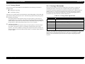
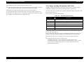
2.1.4 Paper Feeding Mechanism
The paper feeding mechanism consists of Paper feed motor (PF motor), PF roller,
Paper eject roller, Star wheel roller, and so on. The paper feeding mechanism feeds
paper loaded from ASF using the PF roller and Paper Eject Roller & Star wheel roller.
For this mechanism, the PF motor mentioned in the right Table 2-3."PF Motor
Specifications" is used on this product.
The drive of the PF motor is transfer to the PF roller and the Paper Eject Roller as
following Figure 2-8. "Paper Feeding Mechanism". Following shows you how to
transfer the PF motor drive to the PF roller and the Paper Eject Roller.
PF motor drive transmission path
•PF roller path
PF Motor Pinion Gear (CW) Æ Combination Gear 16, 21.6 (CCW) Æ Spur
Gear 73.6 (CW)
Table 2-3. PF Motor Specifications
Item
Description
Motor type
4-Phase/ 200-Pole HB Stepping motor
Drive voltage
+42 V +/ - 5% (DRV IC voltage)
Coil Resistance
7.8 Ω +/ - 10% (25°C, per phase)
Inductance
13.5 mH +/ - 20%(1kH 1Vrms)
Driving method
Bi-Polar drive
Driver IC
LB1946
•Paper eject roller path
PF Motor Pinion Gear (CW) Æ Combination Gear 11.6, 36.8 (CCW) Æ Spur
Gear 25.6 (CW)
Spur Gear 73.6
(PF Roller)
Combination
Gear 11.6, 36.8
Spur Gear 25.6
(Paper Eject Roller)
PF Motor
Combination Gear 16, 21.6
Figure 2-8. Paper Feeding Mechanism
Operating Principles
Overview
36
EPSON Stylus PHOTO 895/785EPX
Paper loaded from ASF is advanced by the following roller.
Paper feed roller & Paper guide roller (assembled on the Top Frame) Æ Paper
eject roller & Star wheel roller (assembled on the Paper eject frame).
Additionally, the top & end of the paper is detected with the PE sensor.
In case the PE sensor dose not detect the paper in the paper loading sequence, the
printer detects the “Paper out error”. If the paper is detected after complete the paper
eject sequence, the printer detects the “Paper jam error”.
Revision A
2.1.5 Paper Loading Mechanism (ASF Unit)
The Paper loading mechanism is positioned at the printer rear. The Paper loading
mechanism loads paper at the ASF unit and feeds paper to the PF roller.
This ASF unit consists of ASF motor, LD roller, Pad holder (Paper return plate), ASF
Frame, Hopper, and so on.
Table shows the ASF motor specifications.
Table 2-4. ASF Motor Specifications
Item
Description
Motor type
4-Phase/ 200-Pole HB Stepping motor
Drive voltage
+42 V +/ - 5% (DRV IC voltage)
Coil Resistance
7.8 Ω +/ - 10% (25°C, per phase)
Inductance
13.5 mH +/ - 20%(1kH 1Vrms)
Driving method
Bi-Polar drive
Driver IC
LB1946
For the major feature of this ASF unit, ASF HP sensor is not used and the single LD
roller is built in the ASF unit.
Drive sent from the ASF motor is always transmitted to the ASF unit side. But, the
Change lever and the Clutch mechanism switch ON/OFF drive to the LD roller.
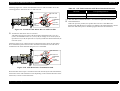
Drive from the ASF motor is transmitted to the ASF unit as described below:
Switch the ASF motor drive to ASF unit side
ASF Motor pinion gear rotates CCW direction with a specific steps
Æ Combination Gear 14.4, 38.4 (CW) Æ Combination Gear 37.6, 44.4 (CCW)
Æ Spur Gear 23.2 (CW) Æ Spur Gear 35.2 (CCW) Æ Release the Clutch
mechanism lock position
Operating Principles
Overview
37
EPSON Stylus PHOTO 895/785EPX
Revision A
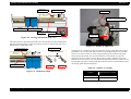
Following Figure 2-9. "Switch the ASF Motor Drive to ASF Unit Side" shows the
switching path for ASF motor drive to ASF unit side.
Table 2-5. ASF Unit Function & ASF Motor Rotational Direction
Directions
Spur Gear 35.2
Change Lever
Clockwise (*1)
• Picks up and loads paper
Counterclockwise (*1)
• Release the DE lever & Clutch mechanism
Spur Gear 23.2
(*1): The ASF Motor rotational direction = seen from the right side of the printer.
Combination
Gear
14.4, 38.4
Combination
Gear
37.6, 44.4
Corresponding Functions
Clutch Mechanism
Unlike the previous products, this product dose not have a ASF HP sensor.
Instead of the ASF HP sensor, Change lever and the Clutch mechanism are used to
detect the ASF home position. Following figures describe the mechanism.
ASF motor
Figure 2-9. Switch the ASF Motor Drive to ASF Unit Side
Transfer the ASF motor drive to LD roller
ASF Motor pinion gear rotates CW directionÆ Combination Gear 14.4, 38.4
(CCW) Æ Combination Gear 37.6, 44.4 (CW) Æ Change Lever rotates (CW) Æ
Spur Gear 23.2 (CCW) Æ Spur Gear 35.2 (CW) (include the clutch mechanism) Æ
LD roller (CW).
Following Figure 2-10, "ASF motor drive transmission path" shows the ASF motor
drive transmission path to the LD roller unit built in the ASF unit. The LD roller is
assembled on the same shaft that spur gear 35.2 is assembled.
Spur Gear 35.2
Spur Gear 23.2
Change Lever
Combination
Gear
14.4, 38.4
ASF motor
Combination Gear
37.6, 44.4
Figure 2-10. ASF Motor Drive Transmission Path
When the ASF motor torque is switched to the ASF unit side by the clutch mechanism,
the function of the ASF mechanism varies depending on the rotational direction of the
ASF motor, as shown in the table below.
Operating Principles
Overview
38
EPSON Stylus PHOTO 895/785EPX
NOTE:
Revision A
Step1
Spur Gear 35.2
Step 2
Step 3
Clutch Gear
Change Lever
Tension Spring 0.143
The Clutch gear is molded on
the back side of the Spur gear
35.2 such as Combination gear.
LD Roller Shaft
Clutch
Clutch Lock Tooth
Clutch Lever
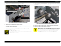
Figure 2-11. Disengage & Clutch mechanism
The Clutch mechanism transmits the ASF motor drive to the LD roller shaft only when
the Clutch gear rotates CW direction after the Change lever releases the Clutch lever. If
the Clutch gear rotates CCW direction, the ASF motor drive is not transmitted to the
LD roller. This is due to the combination of the shape of the Clutch gear and the Clutch
lock tooth such as described on the figure.
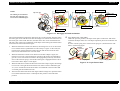
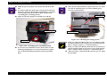
1.
2.
Paper Return Plate (Pad holder)
When the ASF motor rotates CW direction, the Change lever is set on the Clutch
lever and the Clutch is pushed down as above Step1’s figure. As the result, the
Clutch gear is released from the Cluck lock tooth and the drive from the ASF
motor is not transmitted to the LD roller shaft.
When the ASF motor rotates CCW direction in the above Step2’s figure, the
Change lever moves to the left direction with the CCW rotation of Combination
gear 37.6, 44.4. The Clutch turns back to the engagement position by the tension
force of the Tension spring 0.143 and the Clutch gear is engaged with the Clutch
lock tooth as above Step2’s center figure.
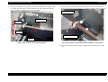
3.
When the ASF motor rotates CW direction in the above Step3’s figure, the Change
lever moves to the right direction with the CW rotation of the Combination gear
37.6, 44.4. And the drive from the PF motor is transmitted to the LD roller shaft
via Clutch gear and Clutch lock tooth.
4.
The LD roller shaft rotates about 360 degree and the Change lever push the Clutch
lever and the ASF motor drive is interrupted. This position is the ASF home
position.
Operating Principles
Overview
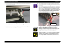
Unlike the previous products, The Paper return plate is built in the ASF frame
instead of the Paper return lever. The Paper separation pad is also stacked on the
plate.
It works with the spring force of the Torsion spring 25.7 (mounted in the ASF
frame) as following figure.
LD Roller
Hopper
Paper Return
Plate
ASF Frame
Torsion Spring 25.7
Compression Spring 4.80
Figure 2-12. Paper Return Plate
39
EPSON Stylus PHOTO 895/785EPX
Revision A
The Paper return plate is set to return the paper to the paper stand-by position in the
ASF unit when the ASF unit is in the standby mode. When the paper is fed with the
LD roller, the Paper return plate is stored in the ASF frame by the LD roller.
Following figures show you the ASF paper loading sequence and the operation of the
each mechanism.
Step 1
Step 2
Hopper
LD Roller
LD Roller Shaft
When the paper is advanced with
the ASF unit, Change lever push
down the Clutch lever as right
figure and the Clutch lock tooth is
disengaged from the Clutch gear.
As the result, the drive from the
ASF motor is interrupted and the
LD roller dose not rotate.
This position is the ASF home
position.
The Paper return plate is set to
avoid that the paper is slipped
down from the paper set position.
Paper Return Plate
Change Lever
Tension Spring 0.143
Clutch Lock Tooth
Clutch
Clutch Lever
ASF Motor Pinion
Gear CW Rotation
The ASF motor pinion gear rotates
CW direction and the drive from the
ASF motor is transmitted to the ASF
LD roller shaft through the Clutch
lock tooth and the Clutch gear.
The ASF hopper release lever rotates
with the ASF LD roller and release
the ASF Hopper. The ASF hopper is
pushed with the Compression spring
4.80 and the paper is picked up with
the ASF LD roller.
Printer Front
Clutch Gear
Step 3
Step 4
ASF Motor Pinion Gear
CCW Rotation
Compression Spring
ASF Hopper
Release Lever
4.80
ASF Frame
Paper Return Plate
LD Roller Shaft
ASF Motor Pinion Gear
CW Rotation
ASF Hopper
Release Lever
When the ASF motor is rotated CCW
direction, the Change lever moves to the
printer front side with the CCW rotation
of the ASF motor pinion gear and
releases the Clutch lever. As the result,
the Clutch turns back to the engagement
position by the tension force of the
Tension spring 0.143.
And the Clutch lock tooth is OK with
the Clutch gear to transmit the ASF
motor drive as right figure.
The ASF LD roller rotates CW direction
moreover and the Paper return plate is
stored under the ASF frame.
The paper is advanced up to the PF roller.
and the ASF LD roller & the clutch rotate
to the “Step1” position. The Clutch lever
is locked with the Change lever.
The drive from the ASF motor is
interrupted and the drive is not
transmitted to the LD roller side.
ASF Motor Pinion Gear
CW Rotation
Figure 2-13. ASF Paper Loading Sequence
Operating Principles
Overview
40
EPSON Stylus PHOTO 895/785EPX
Revision A
2.1.6 Ink System Mechanism
Table 2-6. ASF Motor Rotational Direction & Ink System Mechanism
Ink system mechanism consists of pump unit (include the CR lock lever) and capping
mechanism. Ink system mechanism drives the pump unit that presses cap to the
printhead and ejects ink from ink cartridge, head cavity and cap to the waste ink pad.
Directions
Counterclockwise (*1)
• Sets the wiper.
• Absorbs ink by the pump unit
• Set the CR lock lever
Clockwise (*1)
• Resets the wiper.
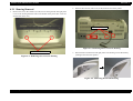
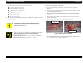
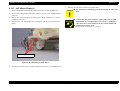
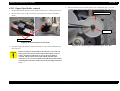
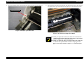
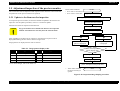
2.1.6.1 Pump Unit & Wiper mechanism
The pump unit is driven by ASF motor. ASF motor drive is always transmitted to the
paper feeding mechanism and pump unit through the following gears. Refer to the
Figure 2-15. "ASF Motor Drive Transmission Path to the Pump Unit".
Functions
(*1): The ASF Motor rotational direction = seen from the right side of the printer.
Following figure shows the overview of the pump mechanism operation
ASF Motor Pinion Gear (CW) Æ Combination Gear 14.4, 38.4 (CCW) Æ Combination
Gear 37.6, 44.4 (CW) Æ Spur Gear 36.8 (CCW) Æ Combination Gear 9.6, 24 (CW)Æ
Pump Unit Gear (CCW)
The Pump unit and Wiper mechanism drives according to the ASF motor rotational
direction, as shown in the right table.
Figure 2-14. Pump Mechanism
ASF
Motor
Combination Gear
37.6, 44.4
Cap unit
Combination Gear 9.6, 24
ASF motor
Pump unit
Pump Unit Gear
Wiper
Combination Gear 14.4, 38.4
Spur Gear 36.8
CR Lock Lever
Figure 2-15. ASF Motor Drive Transmission Path to the Pump Unit
Operating Principles
Overview
41
EPSON Stylus PHOTO 895/785EPX
Revision A
2.1.6.2 Capping Mechanism
The capping mechanism covers the printheads with the cap holder to prevent the nozzle
from increasing viscosity when the printer is in stand-by mode or when the printer is
off. This product has valveless cap system. Air valve function used for the previous
models pumps and ejects ink only inside the cap by absorbing ink with the valve open.
By opening the Air valve, the negative pressure is decreased and only the ink inside the
cap is ejected. (the ink is not absorbed from Ink cartridge or head cavity.)
But, valveless cap system, this operation is done out side of the capping area.
The CR moves to left side of the Cap assembly and the pump absorbs the ink inside the
cap.
Viewed From Front Side
CR Unit
Slider Cap
Printhead
Cap
Slide Up
Waste Ink Tube
Figure 2-16. Cap Mechanism
Operating Principles
Overview
42
EPSON Stylus PHOTO 895/785EPX
Revision A
2.2 Electrical Circuit Operating Principles
2.2.1 C408 PSE board
The electric circuit of the Stylus PHOTO 895/785EPX consists of the following
boards.
The power supply boards of Stylus PHOTO 895/785EPX use a RCC (Ringing Chalk
Converter) circuit, which generates +42VDC for drive line and +5VDC, +3.3VDC for
logic line to drive the printer. The application of the output voltage is described below.
Main board:
C408 MAIN
Power supply board:
C408 PSE
Monochrome panel board:
C408 PNL
Printer panel board:
C408 PNL-B
Table 2-7. Application of the DC Voltages
Voltage
This section provides operating principles of C408 MAIN Board and C408 PSE Board.
Refer to Figure 2-17. "Electric Circuit" for the major connection of the each boards
and their roles.
C408 MAIN Board
Monochrome panel board
Printer panel board
Printon section
Printer Mechanism
CR motor
Application
+42VDC
• Motors (CR Motor, PF Motor, ASF motor)
• Printhead common voltage
• Printhead nozzle selector 42V drive voltage
+5VDC
• C408 MAIN control circuit logic
• Sensor
+3.3VDC
• C408 MAIN control circuit logic
AC voltage input from AC inlet first goes through filter circuit that removes high
frequency components and is then converted to DC voltage via the rectifier circuit and
the smoothing circuit. DC voltage is then lead to the switching circuit and FET Q1
preforms the switching operation. By the switching operation of the primary circuit,
+42VDC is generated and stabilized at the secondary circuit. This +42VDC generated
by the secondary circuit is converted to +5VDC, +3.3VDC by the chopping regulator
IC of the secondary circuit.
PF motor
Printer section
ASF motor
Head Driver Board
HP/PE Sensor
+3.3VDC +5VDC +42VDC
C408 PSE Board
Figure 2-17. Electric Circuit
Operating Principles
Electrical Circuit Operating Principles
43
EPSON Stylus PHOTO 895/785EPX
Revision A
2.2.1.1 Process how 42VDC, 5VDC and 3.3VDC are generated
ZC-RCC converter
• Over current protective
function
• Over voltage protective
function
• Secondary side SW
function with delay circuit
• Power saving mode applied
+42VDC
5V Chopper
Circuit
+5VDC
3.3V Chopper
This section provides the description how +42VDC, +5VDC and +3.3VDC are
generated from the supplied power supply referring to the Figure 2-18, "C408 PSE
Board Block Diagram".
1.
Regardless of the state of the power switch (On or OFF), the voltage is always
applied to the primary side of the power supply board from the moment or at the
state that AC-plug is plugged in. At this time, F1 plays a role of preventing
AC100V from coming into the F1.
L1 also prevents high harmonic wave noise generated in the RC circuit filter
which consists of C1 from going out, and eliminates the noise from outside here.
2.
The AC is full-wave rectified by the diode bridge DB1, and converted to
AC in voltage by the smoothing electrolytic capacitor C11.
3.
The pressured up direct current turns Q1 on through the starting resistor and starts
the primary side of the circuit.
4.
When the primary side is On, the energy (current) led by the electromagnetic
induction through the trans (T1) does not flow to the secondary side since the
diode (D51) on the secondary side is installed in the opposite direction.
5.
When the energy which is charged in the trans is reaching the saturated state, the
voltage which makes Q1 on becomes weak gradually. At the point that this voltage
drops at the certain voltage, C13 absorbs the current in the opposite direction and
Q1 is quickly shut off by the resulting sharp drop.
6.
When the primary side is turned off, the energy charged in the T1 is opened
according to the diode (D51) direction which is installed on the secondary side.
Basically, 42 V DC is output by these circuit operations and the number of T1
spiral coil.
7.
+5VDC and +3.3VDC are generated by pressured down this +42VDC as power
supply. The 5V chopper circuit (IC51) and 3.3V chopper circuit (IC151) pressures
down the +42VDC and generates precise +5VDC and +3.3VDC by chopping off
the output, forming the standard sawtooth wave form by the outer RC integration
circuit.
+3.3VDC
Circuit
PSC signal from
Main board
Energy saving
signal
Smoothing
Circuit
D51
C51, C52
TRANS (T1)
Main Switch
Circuit
Over Current
Protection
F1, TH1
Filter Circuit
L1, C1
Q1
Full Wave
Rectifier
Circuit
DB1
Smoothing
Circuit
C11
AC Input
Figure 2-18. C408 PSE Board Block Diagram
The C408 PSE board has the various control circuits to stop voltage output if a
malfunction occurs on the power supply board or the main board while the printer
mechanism is on duty. Following explains each control and protection circuit.
Operating Principles
Electrical Circuit Operating Principles
2x
44
EPSON Stylus PHOTO 895/785EPX
Revision A
2.2.1.2 Protection circuit
2.2.1.3 PS Control Function
The C408 PSE board has the various control circuits to stop voltage output if a
malfunction occurs on the power supply board or the main board or while the printer
mechanism is on duty. Following explains each control and protection circuit.
This power supply circuit enables to supply the voltage to the 5V, 3.3V and 42V lines
for about 30 seconds by using the secondary power supply even if the power is turned
off with the power switch on the operation panel. This procedure ensures the following
operation even if the printer's power switch is turned off while printing.
+42VDC line constant voltage control circuit:
The output of +42V line is monitored by the ZC-RCC converter detection circuit.
This circuit prevents voltage drop so that the output voltage can be held at a
constant level.
+42V line over current protection circuit:
When the CR unit is not at the home position while the printer is printing, the
CR unit stops printing, then the power is shut down after returning to the
home position and finishing the locking action.
When the papers are stored in the printer mechanism in the condition supplied
The output voltage extremely drops when the +42V line becomes the over current
condition. The ZC-RCC converter feeds back the occurrence of over voltage to the
primary side via the same IC if it detects the voltage drop in the 42V line. The
primary side stops switching and protects the printer electric circuit and
mechanism. Reset is automatically performed.
by the ASF even if the printer is not printing, the paper is ejected and then the
power is shut down.
2.2.1.4 Power saving mode
The power supply circuit activates the power saving mode by the signal ESAVE from
the control circuit. The +42V line repeats rise/fall in the power saving mode.
+42V line over voltage protection circuit:
If the +42V line exceeds 58V, the ZC-RCC converter detects the over voltage and
feeds back the occurrence of over voltage to the primary side via the same IC. The
primary side stops switching and protects the printer electric circuit and
mechanism.
+5VDC, +3.3VDC line constant voltage/current control circuit:
+The +5V and +3.3V line output currents and output voltage are monitored by the
self-excited down chopper circuit (IC51, IC151). The monitor information is input
to the internal comparator and stabilization circuit in IC. The self-excited down
chopper circuit (IC51, IC151) stops the output if the over current is detected.
+5V, +3.3V line over current protection circuit:
The ZC-RCC converter feeds back the occurrence of over voltage to the primary
side via the same IC when the +5V or +3.3V line becomes the over current
condition. The primary side stops switching and protects the printer electric circuit
and mechanism. It is possible to reset only by turning on the power again.
+5V, +3.3V line over voltage protection circuit:
If the +42V line exceeds 9V, the ZC-RCC converter detects the over voltage and
feeds back the occurrence of over voltage to the primary side via the same IC. The
primary side stops switching and protects the printer electric circuit and
mechanism.
Operating Principles
Electrical Circuit Operating Principles
45
EPSON Stylus PHOTO 895/785EPX
Revision A
2.2.2 C408 MAIN Board
The printer mechanism is controlled by C408 MAIN.
See Figure for the C408 MAIN board block diagram.
C408 MAIN Board
Printer section
P-ROM
(IC3)
CN9
Q5, 6
Address
Data
Printon section
D-RAM4M
(IC5)
D-RAM16M
(IC4)
Common Driver
(IC12)
SDRAM
(IC18)
Address
Data
CPU V832
(IC15)
Flash ROM
(IC24)
Head
CN8
CN13
Motor Driver
(IC9)
CN1
E01A22CA
CPUASIC2in1
(IC2)
E05B75B*
ASIC1
(IC22)
CR Motor
CN12
Motor Driver
(IC11)
PF Motor
Reset IC
EEPROM
(IC6)
PCMCIA
Socket power
controller
(IC23)
PCMC
IA
Parallel IF
CN7
CN11
Motor Driver
(IC10)
E09A27A*
ASIC2
(IC17)
ASF Motor
CN4
HP Sensor
USB HUB
IC
(IC20)
CN5
Printer
PNL
CN2
Preview monitor
CN14
Monochrome
PNL
CN3 USB IF
PE Sensor
Figure 2-19. Block Diagram for the C408 MAIN Board
Operating Principles
Electrical Circuit Operating Principles
46
EPSON Stylus PHOTO 895/785EPX
Revision A
Following shows you the major characteristic of this main board.
Use of the newly designed board C408MAIN
This product uses the newly developed C408MAIN board with the PCMCIA card
slot, preview monitor (option) and monochrome panel (LCD) added. This board is
divided into the printer and Printon sections. The same control as the conventional
models is operated in the printer section, and the control for the PCMCIA slot,
monochrome panel and printer PNL is operated in the Printon section.
Applicable to the ECP mode
The parallel IF, which connects the printer and Printon sections, can receive the
high speed data by means of the DMA function up to at the maximum
500 kbytes/second. The product can also receive the data transmitted at the
maximum 800 kbytes/second (ECP mode) in compliance with the IEEE1284 since
it is applicable to the ECP mode.
Applicable to the USB (Universal Serial Bus) Rev.1.1IF (Full speed/12 Mbps.
without a hub)
Motor current control by D/A of CPU and ladder circuit of resistors
Use of united IC of the reset circuit and EEPROM for the simple system design.
Low power consumption is realized by designing logic circuit on the 3.3V power
supply. The following table shows the chips that operate by 3.3V and +5V.
Table 2-8. 3.3V & 5V Drive Chips
+3.3V
+5V
•
•
•
•
• Sensors
• I/F Circuit
• PNL Board
CPU
P-ROM
D-RAM
SD-RAM
Use of the HJFK image processing
SDRAM is mounted.
Operating Principles
Electrical Circuit Operating Principles
47
EPSON Stylus PHOTO 895/785EPX
Revision A
2.2.2.1 Main elements
Table 2-10. Main Elements (Printon section)
Following table provides the description of main element functions on the C408 main
board.
Table 2-9. Main Elements (Printer section)
IC
Location
Location
IC2
16bit CPU mounted on the MAIN board is driven by
clock frequency 24MHz and controls the printer
PROM
IC3
• Capacity 4/8/16MB, Bus= 16 bit
• Program for CPU or Program +CG
DRAM
IC5, IC4
Bus= 16 bit, 4Mbit DRAM and 16Mbit DRAM
IC6
EEPROM section
• Default value setting
• Parameter backup
RESET section
• For +3.3V; reset when +2.5V is detected
• For +5V; reset when +4.2 is detected
• For +42V; reset when +36 is detected
TIMER section
• Electric double layer capacitor (0.33F) is used.
Common Driver
IC12
Head drive control HIC
• Generates head common voltage.
Motor Driver
IC9
CR motor drive IC
Motor Driver
IC11
PF motor drive IC
Motor Driver
IC10
ASF motor drive IC
IC15
•
•
•
•
ASIC1
E05B75B*
IC22
• Package: 208pinPQFP
• Operating frequency: 47.6 MHz and 48 MHz
ASIC2
E09A27A*
IC17
• Data communication with the printer section
• Start and finish of DMA by MWPACKU
• SW condition is read from the printer PNL and
monochrome PNL.
• SW condition to the printer side is set from the CPU
and can be output.
• JFK image processing
• Fraction processing function applicable to the MW
packing function
• Clock synchronous serial interface
• The maximum 160 bit data are serial-exchanged and
transmitted to the LCD drive.
PCMCIA Socket
Power Controller
MAX1602
IC23
Flash ROM
MBM29LV160TC/
BC
IC24
SDRAM
K4S641632D
IC18
Electrical Circuit Operating Principles
USB storage class target
PCMCIA control
Image processing
Operating frequency: 47.6 MHz
• Package: 16 pin S.O Package
USB HUB IC
IC20
TUSB2036VF (TI)
Operating Principles
Function
CPU
V832
Function
CPU-ASIC 2in1
E01A22CA
RTC9822
(Reset function,
RTC, EEPROM
compound IC)
IC
• Capacity: 16/8Mbit Bus=16bit
• Program
• Capacity: 64Mbit (1M x 16bit x 4bank), Bus=16bit
• System memory
• Self power/pass power mode
• Applicable to full speed/low speed related to all
Down Stream ports
• Applicable to the suspend/resume operation
• Suspend/status output
48
EPSON Stylus PHOTO 895/785EPX
Revision A
2.2.2.2 Printhead Driver Circuit
F1
The printhead driver circuit consists of the following two components:
Common driver IC (IC12:E09A14RA) directly attached to the C408 MAIN
board.
Nozzle selector IC on the head board.
The common driver (IC12:E09A14RA) generates a reference drive waveform
according to the output signals from the C408 MAIN board. The reference drive
waveform is amplified by the transistors Q2 and Q3 and then transferred to the nozzle
selector IC on the head board. Print data is converted to serial data by the CPU (IC2)
and then sent to the nozzle selector IC on the head board. Based on the serial data, the
nozzle selector IC determines the nozzles to be actuated. The selected nozzles are
driven by the drive waveforms produced by the common driver. See Figure 2-20.
"Printhead Driver Circuit" for the printhead driver circuit block diagram.
Head common driver circuit
The reference head drive waveform is produced in the common driver
(IC12:E09A12RA) based on the following 12 signal lines output from the CPU
(IC12); A0-A4, CLK1, CLK2, RST, FLOOR, DATA, DCLK, and E.
By the DATA signal output from the CPU (IC9), the original data for the head
drive waveform is written in the memory in the IC12. The addresses for the written
data are determined by the A0 - A4 signals, and, of among, data used to determine
the waveform angles is selected. Then, setting the selected data, producing
trapezoid waveform value, and canceling the data are performed by the rising
edges of the CLK1 and CLK2 signals.
HWA0
HWA1
HWA2
HWA3
HWA4
HWCLK
HWCLK
HWFLR
HWRST
HWSDA
HWSCL
HWSLA
IC2 CPU
E01A22CA
HCH
HLAT
CRAI0
CRAI1
SWC0
SWC1
HSO1
HSO2
HSO3
HSO4
HSO5
HSO6
HSOCM
HNCHG
HSOCLK
ANO
VCC
A0
NPNB
A1
FB
A2
PNPB
A3
A4
CLK1
CLK2
FLOOR
RST
DATA
DCLK
E
CN8
COM
COM
COM
COM
VHV
VHV
CH
LAT
ENA
ENB
IC12
Common
Driver IC
Nozzle Selector
IC
CN9
Head Drive
Pulse
COB
COA
SI1
SI2
SI3
SI4
SI5
SI6
SP
NCHG
SCK
THM
Head nozzle selector circuit
Printing data is converted into serial data by the CPU (IC2). Then the converted
data is allocated to the six rows, the number of the head nozzle rows, to be
transferred to the nozzle selector through the six signal lines (HS01 to HS06). Data
transmission from the CPU (IC2) to the nozzle selector synchronizes with the LAT
signal and SCK clock signal. Referring to the transferred data, nozzles to be
activated are selected, and the PZTs of the selected nozzles are driven by the drive
waveform output from the head common driver.
Operating Principles
Electrical Circuit Operating Principles
Figure 2-20. Printhead Driver Circuit
49
EPSON Stylus PHOTO 895/785EPX
Revision A
2.2.2.3 CR Motor Driver Circuit
2.2.2.4 PF Motor Driver Circuit
The motor driver IC on the MAIN board drives CR motor. This product uses 4-phase
200-pole hybrid type stepping motor and performs constant current bi-polar drive.
The motor driver IC on the MAIN board drives PF motor. This product uses 4-phase
200-pole hybrid type stepping motor and performs constant current bi-polar drive.
CPU (IC2) converts CR motor phase control signal to LB1946 micro step drive form
and outputs to motor driver IC (IC9) LB1946 from the each port. Based on this signal,
IC9 determines the phase mode.
CPU (IC2) converts PF motor phase control signal to LB1946 micro step drive form
and outputs to motor driver IC (IC11) LB1946. Based on this signal, IC11 determines
the phase mode.
The current value on each phase is determined by CPU (IC2) and outputs from the each
port to driver IC (IC9). Motor driver IC generates motor driver waveform based on
these input signals and controls the motor. If the printer dose not receive any data from
PC for 5 minutes, CPU set the motor drive current to 0 via the each port and the motor
drive is turned off to save the power consumption.
The current value on each phase is determined by CPU (IC2) and outputs from the each
port to driver IC (IC11). Motor driver IC generates motor driver waveform based on
these input signals and controls the motor. If the printer dose not receive any data from
PC for 5 minutes, CPU set the motor drive current to 0 via the each port 104 and the
motor drive is turned off to save the power consumption.
CR_SCLK 17
LB1946
(IC9)
23 CLK
OUTA 7
CR_DATA 18
22 DATA OUTA- 5
CR_LAT 19
21 SET
9
27 VREF1 OUTB
2
OUTB- 8
4
E01A22CA
(IC2)
4
C-P46
C-P25 27
+5V
16 VREF2
24
25
18
3
12
20
15
17
19
26
MD
CR1
CR2
E1
E2
ST
GND
NC
NC
NC
E01A22CA
(IC2)
1
PF_SCLK 24
3
25
+42V
VBB 1
NC
NC
NC
NC
NC
NC
+5V
27
OUTB 9
2
OUTB- 8
4
27 VREF1
15 VREF2
+3.3V
24
25
18
3
12
20
15
17
19
26
+5V
2
4
5
10
11
13
Figure 2-21. CR Motor Driver Circuit Block Diagram
Operating Principles
3
PF_LAT 26
C_P25
VBB 14
VCC 28
Rotor
1
22 DATA OUTA- 5
21 SET
PF_DATA
CN13
LB1946
(IC11)
23 CLK OUTA 7
MD
CR1
CR2
E1
E2
ST
GND
NC
NC
NC
CN12
VBB 14
VBB 1
VCC 28
NC
NC
NC
NC
NC
NC
Rotor
+42V
+5V
2
4
5
10
11
13
Figure 2-22. PF Motor Driver Circuit Block Diagram
Electrical Circuit Operating Principles
50
EPSON Stylus PHOTO 895/785EPX
Revision A
2.2.2.5 ASF Motor Drive Circuit
2.2.2.6 Reset and EEPROM circuits
The motor driver IC on the MAIN board drives the ASF motor. This product uses 4phase 200-pole hybrid type stepping motor and performs constant current bi-polar
drive.
Unlike the previous products, this product uses IC in which reset circuit and EEPROM
are united.
CPU (IC2) converts ASF motor phase control signal to LB1946 micro step drive form
and outputs to motor driver IC (IC10) LB1946 from each port. Based on this signal,
IC10 determines the phase mode.
The current value on each phase is determined by CPU (IC2) and outputs from each
port to driver IC (IC10). Motor driver IC generates motor driver waveform based on
these input signals and controls the motor. If the printer does not receive any data from
PC for 5 minutes, CPU set the motor drive current to 0 via each port and the motor
drive is turned off to save the power consumption.
E01A22CA
(IC2)
ASF_SCLK 21
ASF_DAT 22
23
ASF_LAT
3
C_P47
C_P25 27
+5V
LB1946
(IC10)
23
OUTA 7
CLK
22
21
27
16
24
25
18
3
12
20
15
17
19
26
VREF1
VREF2
MD
CR1
CR2
E1
E2
ST
GND
NC
NC
NC
Reset circuit RTC9822 (IC6), which monitors three types of voltage; logic group
(+3.3V, +5V) and power group (+42V), is mounted on the C408MAIN board.
Each reset circuit monitors the voltage of +3.3V, +5V and +42V and prevents the
operation failure of printer by resetting CPU and ASIC if any failure is detected. It
is possible for this IC to monitor the +3.3V, +5V and +42V lines by one IC and
performs resetting on each voltage. Following circuit diagram shows the structure
of reset circuit.
+5V
+42V
CN11
2
OUTB- 8
4
Rotor
14
12 VDD
8 VI5
10 VDD2
VEX
+42V
VSS
1
MON
6
VBB 1
NC
NC
NC
NC
NC
NC
CPUASIC2in1
(IC2)
RTC9822
(IC6)
7
VBB 14
VCC
+3.3V
3
OUTB 9
28
2
4
5
10
11
13
+3.3V
1
DATA OUTA- 5
SET
Reset Circuit
IRQ
CE 5
CLK 4
DI 3
DO 2
EXO 9
13
FRST 11
RST
128
129 C_P20
130 C_P21
133 C_P22
C_P23
135
126 NMILVL
MRES
134 RESET
+5V
Figure 2-24. Reset EEPROM Circuit Diagram
+3.3V line reset circuit
Figure 2-23. ASF Motor Driver Circuit Block Diagram
Operating Principles
The 3.3V line is monitored at the VDD port of IC6. It outputs the reset signal
from the FRST port to the CPU ASIC if the irregular voltage (2.5V or less) is
detected.
Electrical Circuit Operating Principles
51
EPSON Stylus PHOTO 895/785EPX
Revision A
+5V line reset circuit
The 5V line is monitored at the VDD port of IC6. It outputs the reset signal from
the RST port to the CPU ASIC if the irregular voltage (4.2V or less) is detected.
+42V line reset circuit
the paper path. This sensor outputs the LOW signal when there is no paper in the
paper path. This condition is always monitored with this sensor while the printer
power is turned on.
Thermistor (THM)
The 42V line is monitored at the VEX port of IC6. It outputs the reset signal
from the EXO port to the CPU, ASIC if the irregular voltage (36.0V or less) is
detected.
NOTE: IC6 also contains the RTC (Real Time Clock) function and performs the
timer control function by the BAT1 power supply while the power is
turned OFF.
The thermistor is attached directly on the printhead driver board. It monitors the
temperature around the printhead and determines the proper head drive voltage
according to the ink viscosity that varies by the temperature. This information is
fed back to the CPU analog port. When the temperature rises, the head drive
circuit lowers the drive voltage: When the temperature lowers, the head drive
circuit rises the drive voltage.
EEPROM Control Circuit
Since EEPROM is nonvolatile memory, it keeps written information if the printer
power is turned off. Various adjustment values, factory shipment data and printer
condition values are written and stored in EEPROM. (Figure 2-24. "Reset
EEPROM Circuit Diagram")
The block diagram for the sensor circuit is shown below
IC2
E01A22CA
EEPROM is connected to CPU with 4 lines and each line has the following function.
CE:
CLK:
DI:
DO:
Chip selection signal
Data synchronism clock pulse
Data writing line (serial data) at power off.
Data reading line (serial data) at power on.
C_P15
C_P17
2.2.2.7 Sensor Circuit
C408 MAIN is equipped with the following three sensors to detect the status of the
printer. Unlike the previous product, ASF HP sensor is not equipped on the ASF and
the ASF HP is determined with the clutch mechanism (2.1.5 "Paper Loading
Mechanism (ASF Unit)").
145
144
HPV
3
GND
2 CH4 HP Sensor
HP
1
PEV
3
GND
2 CH5 PE Sensor
PE
1
THM
13 CN9 Head FFC
Figure 2-25. Sensor Circuit Diagram
HP Sensor
This sensor uses the photoelectric conversion method and detects the CR home
position at the right end of CR shaft by the HP sensor when the power is turned on.
This sensor outputs the HIGH signal to the CPU as it detects the CR home position
when the power is turned on. If the LOW signal is outputted at the detection
position, the CR unit is not at the home position.
PE sensor
This sensor uses the photoelectric conversion method and detects if there is paper
in the ASF unit or not. This sensor outputs the HIGH signal when there is paper in
Operating Principles
Electrical Circuit Operating Principles
52
CHAPTER
3
TROUBLESHOOTING
Download Free Service Manual and Resetter Printer at http://printer1.blogspot.com
EPSON Stylus PHOTO 895/785EPX
Revision A
3.1 Overview
Table 3-1. Motor, Coil Resistance
This chapter describes how to identify troubles in two levels: unit level repair and
component level repair. Refer to the flowchart in this chapter to identify the defective
unit and perform component level repair if necessary. This chapter also explains motor
coil resistance, sensor specification and error indication.
Motor
Location
Check Point
Resistance
CR Motor
CN13
Pin 1 and 3
Pin 2 and 4
7.8 Ohms ± 10%
(25 °C/ phase)
PF Motor
CN12
Pin 1 and 3
Pin 2 and 4
7.8 Ohms ±10%
(25 °C/ phase)
ASF Motor
CN11
Pin 1 and 3
Pin 2 and 4
7.8 Ohms ±10%
(25 °C/ phase)
START
Unit level Troubleshooting
Table 3-2. Sensor Check Point
Sensor Name
Check Point
Unit repair
HP Sensor
END
Thermistor (THM)
Switch Mode
0.7V less than
OFF
• HP Out of range
2.4V more than
ON
• Within HP range
0.7V less than
OFF
• No paper
2.4V more than
ON
• Detect paper
Analog signal
10 K (24 °C)
CN4/Pin 1 and 3
Assemble & Adjustment
PE Sensor
Signal Level
CN5/Pin 1 and 3
On the Head driver
board
Figure 3-1. Troubleshooting Flowchart
Troubleshooting
Overview
54
EPSON Stylus PHOTO 895/785EPX
Revision A
3.2 Troubleshooting with LED Error Indications
This section describes how to troubleshoot the problem when the printer indicates an
error at power on and can not print. The Stylus PHOTO 895/785EPX can detect the
printer condition and errors, and indicates them with the LED on printer panel and LCD
on the monochrome panel. Following table shows the LED and LCD indications.
"-": No change.
"A->B": A is a indicator condition when carriage is on Home Position
B is a indicator in ink exchange sequence.
•Blink: Repeats lighting on for 0.5 sec.+ off for 0.5 sec.
•Blink2: Repeats lighting on for 0.2 sec.+ off for 0.2 sec. + on for 0.2 sec.+ off
for0.4 sec.
Table 3-3. Error LED Indication
Printer Status
Power ON
Error
Priority
-
10
Ink sequence proceeding
-
6
Ink cartridge changing
-
5
Data processing
-
9
Paper out
On
4
Paper jam condition
On
3
Ink end (black)
On -> Blink
8
Ink low (black)
Blink
8
Ink end (color)
On -> Blink2
8
Ink low (color)
Blink
8
On -> On
8
On
7
Reset, Timer IC reset, EEPROM clear
On (1s)
-
Ink overflow counter reset
On (2s)
-
Blink
2
On
1
Blink2
-
Ink end (both color, black)
No ink cartridge (color or black)
Maintenance request
(Ink overflow counter)
Fatal error
Special setting
Troubleshooting
Table 3-4. Error LCD Indication
Display
(First
line)
Display
(Second
line)
Remarks
No ink (black)
Err
IEb
-
No ink (color)
Err
IEc
No paper
Err
PE
-
Paper jam
Err
PJ
-
No ink
cartridge/abnormality
Err
IC
-
Maintenance required
Err
Sr
-
Printon
Memory card error
Err
CE
When an error occurred
during reading data from a
memory card
Common
Fatal error
Err
FE
Unrecoverable error
Source
Printer
Detail of error
Troubleshooting with LED Error Indications
55
EPSON Stylus PHOTO 895/785EPX
Revision A
Following table describes the possible causes when the error is indicated with
LED and LCD, or troubles in other conditions.
Table 3-5. Error Condition and possible cause
Symptom
• Count up of the protection counter
Table 3-5. Error Condition and possible cause
Symptom
Possible Cause
Check table
Paper out error indication
(Paper is not loaded
correctly)
• The friction of the LD roller is lowered due
to the paper dust.
• The clutch mechanism is broken.
Table 3-6
• Tension spring 0.143 come off in the clutch
"Paper out error
mechanism.
indication"
• Compression spring 4.8 comes off.
• Tip of Change lever has any damage.
• ASF motor is broken.
Paper jam error indication
• Star wheel assembly is not assembled on the
Paper eject frame.
• The Spur gear 25.6 is not assembled
correctly.
• The paper guide front is not assembled
correctly or has any damage.
• The PE detection lever dose not move
smoothly.
No ink cartridge error / No
ink error
Multiple papers are always
loaded
Paper is always loaded
without any print job
Troubleshooting
Table 3-7
"Paper jam
error
indication"
• Ink cartridge installation faulty.
• Head FFC connection faulty.
• Ink cartridge CSIC faulty.
Table 3-8 "No
Ink Cartridge or
Ink Out error
indication"
• The paper return plate dose not work
correctly.
Table 3-9
"Multiple
papers are
always loaded"
• The Change lever is broken in the Clutch
mechanism.
Possible Cause
Table 3-10
"Paper is
always loaded
without any
print job"
Maintenance request error
Fatal error indication
Any error indication is not
displayed. But the paper is
not loaded completely.
Any error indication is not
displayed. But, the paper is
not ejected completely.
Paper jam dose not occur.
Dot missing occur and it is
not recovered with CL
Troubleshooting with LED Error Indications
Check table
Table 1-6
"Special
Setting Mode"
• HP sensor lever or PE sensor lever dose not
move smoothly.
• HP/PE sensor is defective.
Table 3-11
• CR motor is defective.
"Fatal Error
• ASF motor is defective.
indication"
• Main board is defective.
• Printer Housing dose not secured with screw
on -the printer mechanism.
• PF motor is defective.
• PF motor is disengaged from the PF roller
gear.
Table 3-12
"Paper is not
loaded
completely
without any error
indication"
• Paper eject roller gear is disengaged from the
pump’s gears.
• The Paper eject frame is not assembled in the
Paper eject frame.
Table 3-13
"Paper is not
ejected
completely
without any
error
indication"
• Pump unit dose not absorb the ink from the
printhead.
• Cap unit dose not stick on the surface of the
printhead completely.
• The printhead is broken.
• The head FFC has any damage.
• The main board is defective.
Table 3-14
"Dot missing
occur and it is
not recovered
with CL"
56
EPSON Stylus PHOTO 895/785EPX
Revision A
Table 3-5. Error Condition and possible cause
Symptom
Print quality is not good
• Vertical banding
• Horizontal banding
• Printing is blurred
• Ink stains the paper
Possible Cause
Check table
• The accuracy of the CR motor is lowered.
• The lack of the lubricant around the CR unit.
• The both I/C is not held in the CR unit
securely.
Table 3-15
• The Paper eject frame is deformed.
"Print quality is
• Any foreign material is sticking around the not good"
printhead.
• Paper feed accuracy is lowered.
• Printer driver setting is not suitable.
• Paper path has ink stain somewhere.
If the problem fits to the detail phenomenon in the table, make sure the check point and
repair the product following the corresponding remedy mentioned in the table when
you find the defective parts in the check point.
Table 3-6. Paper out error indication
Step
No.
1
Detail phenomenon
Check point
Remedy
ASF LD roller attempt • Check the surface of the • Set a cleaning sheet in the
LD roller if the micro
ASF up side down. Then
to load the paper.
pearl or severe smear is
holding the top edge, try
But, paper is not loaded
adhered.
to load the paper from the
at all. The LD roller
Printer driver. The micro
seems slipping.
pearl on the LD roller
surface is removed. To
remove severe smear,
staple a cloth moistened
with alcohol to a post card
and clean the roller in the
same manner.
LD roller
If it is no problem,
proceed the next step.
Non-adhesive Area
(Use a post card for
the base sheet)
CL Sheet
Adhesive Area
This side down
Staplers
Cloth moistened
with alcohol
• If the problem is not
solved, replace the LD
roller with new one.
Troubleshooting
Troubleshooting with LED Error Indications
57
EPSON Stylus PHOTO 895/785EPX
Revision A
Table 3-6. Paper out error indication
Step
No.
Detail phenomenon
Check point
ASF LD roller does not • Check if the clutch
tooth is broken.
rotate. But, the ASF
motor and Spur gear
Clutch tooth
35.2 is rotating.
Table 3-6. Paper out error indication
Remedy
Step
No.
• Replace the clutch
mechanism with new one.
Detail phenomenon
Check point
When the print data is 1. Check if the tip of the
Change lever has any
sent to the printer, ASF
damage.
LD roller continue to
Change lever
load the paper even if
the first paper is loaded
to the PF roller and the
paper is ejected while
the ASF hopper is
flapping.
Spur gear 35.2
2
Remedy
1. Replace the Change lever
with new one.
4
If it is no problem,
proceed the next step.
ASF LD roller does not 1. Check if the tension
spring 0.143 comes off
rotate. But, the ASF
in the Clutch
motor and Spur gear
mechanism.
35.2 is rotating.
comp. spring 2.94
2. Set the Compression
2. Check if the
spring 2.94 in the Change
Compression spring
lever.
2.94 comes off from the
Change lever.
If it is no problem, proceed
the next step.
1. Se the tension spring
0.143 in the clutch
mechanism.
Tension spring 0.143
3
5
If it is no problem,
proceed the next step.
Troubleshooting
Paper is loaded. But, paper 1. Check if the PE sensor 1.
work correctly by using
is loaded again, and paper
the tester.
out error is indicated.
Refer to Table 3-2
"Sensor Check Point"
2. Set the Compression
spring 1.47 in the Change
lever.
Troubleshooting with LED Error Indications
Replace the PE sensor
with new one.
2. If the problem is not
solved, replace the Main
board with new one.
58
EPSON Stylus PHOTO 895/785EPX
Revision A
Table 3-7. Paper jam error indication
Table 3-7. Paper jam error indication
Step
No.
Detail phenomenon
Paper is not ejected
completely and jammed
around the Paper eject
frame.
1
Check point
Remedy
• Check if the star wheel • Remove the jammed
assembly is assembled
paper and assemble the
in the Paper eject frame.
Star wheel assembly in the
Paper eject frame
completely.
Star wheel assy
If the hook portion of the
Star wheel assembly is
broken, replace the Star
wheel assembly with new
one.
Step
No.
Detail phenomenon
The paper is jammed
around the Front paper
guide.
Check point
1. Check if the Front paper 1. Assemble the Front paper
guide is floating from
guide front to the suitable
the assemble position.
portion and confirm the
PF grounding spring is
2. Check if there is any
securing the Front paper
damage around the rear
guide.
edge of the each rib on
the Front paper guide
PF grounding spring
3
If it is no problem, proceed
the next step.
Ditto
Front Paper guide
• Check if the Paper eject • Set the tip of the Spur gear
roller is rotating
25.6 to the Combination
correctly.
gear 11.6, 36.8 and
assemble it correctly.
Front paper guide
If it is no problem, proceed
the next step.
Paper eject roller
2
Spur gear 25.6
If it is no problem, proceed
the next step.
Remedy
4
Paper is loaded correctly • Check if the Torsion
spring 0.22 comes off
from ASF.
on the both PE sensor
But, after complete the
lever.
print job, paper jam
indicated on the screen
Tension spring
0.22
without any paper jam.
If you send the new print
job in this condition, the
General error is
indicated on the screen.
2. Replace the Front paper
guide with new one.
• If the Torsion spring 0.22
is not set on the correct
position, set it correctly. If
any paper dust is placed
around the PE sensor
lever, remove it.
PE sensor lever
If it is no problem, proceed
the next step.
Troubleshooting
Troubleshooting with LED Error Indications
59
EPSON Stylus PHOTO 895/785EPX
Revision A
Table 3-7. Paper jam error indication
Step
No.
5
Detail phenomenon
Check point
1. Check if the CN4
When the paper is
connector cable for PE
loaded from the ASF
sensor cable is
and ejected without any
disconnected on the
printing. After eject the
Main board or sensor.
paper, paper eject
sequence is continued. 2. Check if the PE sensor
operates correctly by
using the tester. Refer
to Table 3-2 "Sensor
Check Point".
Table 3-9. Multiple papers are always loaded
Remedy
Step
No.
1. Connect the CN4
connector cable to the
CN4 on the Main board.
2. Replace the PE sensor
with new one.
Any error indication is
not displayed on the
monitor. But, multiple
papers are always
loaded from ASF.
1
Detail phenomenon
Check point
A [No Ink Cartridge] or 1. Check to ascertain that
an ink cartridge has
[Ink Out Error] message
been set in place.
is displayed when the
power to the printer is
2. Check the remaining
switched on.
ink with the printer
driver or STM3.
3. Check to ascertain that
the head FFC is been
attached correctly to the
head.
4. Check if the head FFC
has any damaged.
5. Check if the I/C works
correctly.
Troubleshooting
Check point
Check if the Paper return • Assemble the torsion
spring 25.7 in the ASF
plate is operating correctly
frame.
in the ASF when the paper
is loaded.
3. If the problem is not
solved, replace the Main
board with new one.
Remedy
Remedy
1
Torsion spring 25.7
Table 3-8. No Ink Cartridge or Ink Out error indication
Step
No.
Detail phenomenon
Table 3-10. Paper is always loaded without any print job
Step
No.
1. Set the ink cartridge in
place.
Detail phenomenon
Check point
Remedy
Paper is always loaded 1. Check if the tip of the 1. Replace the Change lever
Change lever has any
with new one.
from ASF without any
damage.
print job.
ASF hopper continue to 2. Check if the
2. Set the Compression
flapping when the
Compression spring
spring 2.94 in the Change
printer is turned on.
2.94 comes off from the
lever.
Change lever.
2. Remove and then reset the
ink cartridge in place.
3. Connect the Head FFC.
1
Change lever
4. Replace the Head FFC.
5. Replace the ink cartridge
(faulty CSIC.)
6. If the problem is not
solved, replace the Main
board with new one.
Troubleshooting with LED Error Indications
comp. spring 2.94
60
EPSON Stylus PHOTO 895/785EPX
Revision A
Table 3-11. Fatal Error indication
Table 3-11. Fatal Error indication
Step
No.
Detail phenomenon
Check point
Remedy
Step
No.
4. If the problem is not
solved, replace the Main
board with new one.
Troubleshooting
Remedy
2
3
1. Check if the ASF
1. Connect the ASF motor
When the printer is
motor connector is
connector to the CN11 on
turned on, ASF motor
connected
to
the
CN11.
the Main board.
dose not rotate at all in
the power on sequence. 2. Check if the ASF
2. Replace the ASF motor
motor coil resistance is
with new one.
about 7.8 ohm by using
tester.
3. If the problem is not
solved, replace the Main
board with new one.
Torsion spring 0.22
2. Check if the HP sensor 2. Connect the HP sensor
connector cable is
connector cable to the
connected on the CN4
CN4 on the Main board.
on the Main board or
sensor.
3. Check if the HP sensor 3. Replace the HP sensor
work correctly by using
with new one.
the tester.
Refer to Table 3-2
"Sensor Check Point"
Check point
1. Check if the CR motor 1. Connect the CR motor
When the printer is
connector is connected
connector to the CN13 on
turned on, the CR unit
CN13 on the Main
the Main board.
dose not move at all in
board.
the power on sequence.
2. Check if the coil
2. Replace the CR motor
resistance of the CR
with new one.
motor is about 7.8ohm
by using the tester.
Refer to Table 3-1
"Motor, Coil
Resistance".
3. If the problem is not
solved, replace the Main
board with new one.
1. Check if the Torsion
1. Set the Torsion spring
When the printer is
spring
0.22
comes
off
on
0.22 on the HP sensor
turned on, Fatal Error is
the both HP sensor lever. lever.
indicated after the
Carriage is moved.
HP sensor lever
1
Detail phenomenon
Troubleshooting with LED Error Indications
61
EPSON Stylus PHOTO 895/785EPX
Revision A
Table 3-11. Fatal Error indication
Step
No.
Detail phenomenon
When the printer is
turned on, it sounds
strange noise and the
CR unit is stopped
around the CR lock
lever.
Check point
Table 3-11. Fatal Error indication
Remedy
Step
No.
1. Check if the Top
1. Secure the Housing fixing
housing is secured with
screw at the printer front
the fixing screw at the
side.
front side.
Detail phenomenon
Ditto
Top housing
4
4
2. Check if the Change
lever is placed to the
printer front side.
Change lever
2. Turn back the Change
lever to the printer back
side with the tweezer or
small screw driver.
Check point
Remedy
4. If the CR lock lever is 4. Change the damaged gear
not released even if the
with new one.
ASF motor rotate in the
power on sequence,
check if one of the
gears has any damage
in the ASF motor
torque transportation
path.
Refer to Figure 2-15.
5. If the problem is not
"ASF Motor Drive
solved, replace the Main
Transmission Path to
board with new one.
the Pump Unit" to the
Pump unit.
3. Check if the ASF motor 3. Connect the ASF motor
is operated. Check the
cable to CN11 on the
CN11 connector and
Main board.
Replace the ASF motor
the coil resistance for
ASF motor.
with new one.
Troubleshooting
Troubleshooting with LED Error Indications
62
EPSON Stylus PHOTO 895/785EPX
Revision A
Table 3-12. Paper is not loaded completely without any error indication
Step
No.
Detail phenomenon
In the ASF sequence,
the paper is loaded.
But, PF roller does not
rotate and paper is not
loaded completely.
1
Check point
Remedy
Table 3-13. Paper is not ejected completely without any error indication
Step
No.
Detail phenomenon
Check point
Remedy
Printing is normal. But, 1. Check if the Paper eject 1. Assemble the Spur gear
roller rotate when the
25.6 to the Combination
the paper is not ejected
paper
is
ejected.
gear 11.6, 36.8.
completely and the
bottom area stay around
Right Side of printer
the Paper eject frame.
1. Check if the PF motor 1. Connect the PF motor
connector to the CN12.
connector is connected
to the CN12.
2. Check if the PF motor 2. Replace the PF motor.
coil resistance is about
7.8 ohm by using tester.
3. PF motor drive in not
3. Check if the PF motor,
transmitted to the PF
Spur Gear 73.6 and
roller.
Combination Gear 16,
21.6 are meshed correctly.
Spur Gear 25.6
PF Motor
Combination Gear 11.6, 36.8
Right Side of printer
Spur Gear 73.6
2. Check if the Paper eject 2. Secure the Paper eject
frame is secured with
frame with the three
the three fixing screws
fixing screws to the Main
to the Main frame.
frame.
PF Motor
Combination Gear 16, 21.6
1
Paper Eject Frame
4. If the problem is not
solved, replace the Main
board with new one.
Screws
Troubleshooting
Troubleshooting with LED Error Indications
63
EPSON Stylus PHOTO 895/785EPX
Revision A
Table 3-14. Dot missing occur and it is not recovered with CL
Table 3-14. Dot missing occur and it is not recovered with CL
Step
No.
Detail phenomenon
Check point
Remedy
Step
No.
Detail phenomenon
Ditto
In the CL sequence, the 1. Check if ink is ejected 1. If ink is not ejected at all
to the waste ink pad via
to the waste ink pad in the
pump unit seems work
pump
unit
in
the
CL
CL sequence, proceed the
correctly. But, ink is
sequence.
following check point 2).
not ejected to the waste
ink pad at all.
2. Check if there is any
2. Remove the foreign
foreign material around
material around the seal
Moreover, any ink is not
the seal rubber parts on
rubber parts.
absorbed from the head
the cap assembly.
to the cap.
Check point
5. Check if the Pump
tube is connected to
the bottom of the Cap
assembly correctly
Remedy
5. Connect the Pump tube to
the bottom of the Cap
assembly deeply.
Pump tube
connection point
1
Cap seal rubber parts
1
3. Check if any damage is 3. Replace the Cap assembly
observed around the
with new one.
seal rubber parts on the
cap assembly.
4. Check if the two
4. Set the Compression
compression spring
spring into the Cap
are assembled in the
assembly.
Cap assembly correctly.
6. Check if the pump tube 6. Pump unit may coil the
has a little slack
pump tube inside the unit.
between the Cap
In this case, pull out the
assembly and the pump
coiled tube from the
unit when the Cap
pump unit carefully.
assembly is slide up
After that, connect the
completely.
pump tube to the Cap
Tube
assembly after placing the
tube correctly.
Cap assy
Pump unit
7. If the problem is not
solved, replace the Pump
unit with new one.
Compression
spring
Troubleshooting
Troubleshooting with LED Error Indications
64
EPSON Stylus PHOTO 895/785EPX
Revision A
Table 3-14. Dot missing occur and it is not recovered with CL
Step
No.
Detail phenomenon
Check point
Remedy
2
1. Check if the segment in 1. Replace the I/C with new
In the CL sequence,
the nozzle check patter
one in the I/C replacement
ink is ejected to the
is reduced every CL &
sequence.
Waste ink pad (this
Nozzle check pattern
means pump unit & cap
printing.
unit are working
correctly). But, the dot 2. Check if any damage is 2. Replace the Head FFC
missing is not solved at
observed on the Head
with the new one.
the specific nozzles
FFC.
even if the several CLs
3. Replace the printhead
are performed.
with new one.
3
In the CL sequence, ink
is ejected to the Waste
ink pad. But, dot
missing is occurred on
all nozzle in the printing
and is not solved in the
several CLs.
1. Check if the Head FFC 1. Connect the Head FFC
securely to the CN8 and
is connected to the CN8
CN9 on the Main board or
and CN9 on the Main
Printhead.
board or Head FFC.
2. Replace the Printhead
with new one.
3. Replace the Main board
with new one.
Table 3-15. Print quality is not good
Step
No.
Detail phenomenon
Check point
Remedy
Uneven vertical banding 1. Check if each segment is 1. Perform the CL and check
printed correctly in the
the nozzle check pattern.
is appeared against the
nozzle
check
pattern.
CR movement direction.
2. Check if the surface of 2. Clean the surface of the CR
the CR guide shaft dose
guide shaft with the dry
not have any sever stain.
soft cloth and lubricate G56 inside the CR guide
shaft.
CR Movement
Direction
3. Check if the surface of 3. Clean the surface of the CR
the CR sliding portion on
sliding portion on the Paper
the Paper eject frame has
eject frame and lubricate
enough oil.
specific amount of the
G-26.
1
G26 Lubrication
4. Reassemble the CR guide
4. Check if the CR guide
shaft into the mounting slat
shaft is assembled in the
on the both side frame and
correct portion securely.
secure it with Rod spring.
5. Check if the surface of 5. Replace the CR guide shaft
with new one.
the CR guide shaft is flat.
6. Check if the surface of
the Paper eject frame is
flat.
Troubleshooting
Troubleshooting with LED Error Indications
6. Replace the Paper eject
frame with new one.
7. Replace the following
parts.
• CR motor
• CR timing belt
• Compression spring 19.6
65
EPSON Stylus PHOTO 895/785EPX
Revision A
Table 3-15. Print quality is not good
Step
No.
Detail phenomenon
Micro banding appears
horizontally against the
paper feeding direction
and it appears with the
same width.
CR Movement
Direction
2
Printing is blurred
3
Troubleshooting
Check point
Table 3-15. Print quality is not good
Remedy
1. Check if each segment is 1. Perform the CL and check
printed correctly in the
the nozzle check pattern.
nozzle check pattern.
by using the Adjustment
program.
2. Check if the suitable
2. Use the suitable paper
paper is used according
according to the printer
to the printer driver
driver setting.
setting.
3. Check if the Paper feed 3. Clean the surface of the PF
roller is dirty.
roller carefully with the
soft brush
4. Check if the following 4. Replace the damaged parts
parts do not have any
with new one.
damage.
• Combination gear 16,
21.6
• Combination gear 11.6,
36.8
• Spur gear 73.6
• Spur gear 25.6
5. Replace the Printhead with
new one.
Step
No.
Detail phenomenon
Ink stains the paper
4
Check point
Remedy
1. Check if the following
parts are stained with
ink.
• Upper paper driven roller
• PF roller
• Paper guide front
• Paper eject roller
2. Check if there is some
ink drops around the
backside of the
printhead.
3. If there is ink smudging
the bottom of the printed
paper, check if the paper
eject frame is not bent
up.
4. If the bottom area of the
printed paper has ink
stain, check if the Paper
eject frame is bent
upward.
1. Clean the ink stained parts
with soft cloth.
2. Wipe off the ink drop with
the soft cloth carefully.
3. Secure the screws fixing
the Paper eject frame.
4. Replace the Paper eject
frame with new one.
1. Check if the suitable
1. Use the suitable paper
paper is used according
according to the driver
to the printer driver
setting.
setting.
2. Check if the correct head 2. Input 13 digits code of the
ID is stored in the
head ID into the EEPROM
EEPROM by using the
by using the Adjustment
Adjustment program.
program.
Troubleshooting with LED Error Indications
66
CHAPTER
4
DISASSEMBLY AND ASSEMBLY
Download Free Service Manual and Resetter Printer at http://printer1.blogspot.com
EPSON Stylus PHOTO 895/785EPX
Revision A
4.1 Overview
4.1.1 Precautions
This section describes procedures for disassembling the main components of the
product. Unless otherwise specified, disassembly units or components can be
reassembled by reversing the disassembly procedure. Things, if not strictly observed,
that could result in injury or loss of life are described under the heading “Warning”.
Precautions for any disassembly or assembly procedures are described under the
heading “CAUTION”. Chips for disassembling procedures are described under the
heading “CHECK POINT”.
If the assembling procedure is different from the reversed procedure of the
disassembling, the procedure is described under the heading “REASSEMBLY”.
Any adjustments required after disassembling the units are described under the heading
“ADJUSTMENT REQUIRED”. When you have to remove any units or parts that are
not described in this chapter, refer to the exploded diagrams in the appendix.
See the precautions given under the handling “WARNING” and “CAUTION” in the
following column when disassembling or assembling the product.
Disconnect the power cable before disassembling or assembling
W A R N IN G
the printer.
If you need to work on the printer with power applied,
strictly follow the instructions in this manual.
Wear protective goggles to protect your eyes from ink. If ink gets
Read precautions described in the next section before starting.
Disassembly and Assembly
Overview
in your eye, flush the eye with fresh water and see a doctor
immediately.
Always wear gloves for disassembly and reassembly to avoid
iujury from sharp metal edges.
To protect sensitive microprocessors and circuitry, use static
discharge equipment, such as anti-static wrist straps, when
accessing internal components.
Never touch the ink or wasted ink with bare hands. If ink comes
into contact with your skin, wash it off with soap and water
immediately. If irritation occurs, contact a physician.
When a lithium battery is installed on the main board of this
printer, make sure to observe the following instructions when
serving the battery:
1.Keep the battery away from any metal or other batteries so that
electrodes of the opposite polarity do not come in contact with
each other.
2.Do not heat the battery or put it near fire.
3.Do not solder on any part of the battery. (Doing so may result in
leakage of electrolyte from the battery, burning or explosion. The
leakage may affect other devices close to the battery.)
4.Do not charge the battery. (An explosion may be generated inside
the battery, and cause burning or explosion.)
5.Do not dismantle the battery. (The gas inside the battery may hurt
your throat. Leakage, burning or explosion may also be resulted.)
6.Do not install the battery in the wrong direction. (This may cause
burning or explosion.)
Danger of explosion if the battery is incorrectly replaced.
Replace only with the same or equivalent type recommended by
the manufacture. Dispose the used batteries according to
government’s law and regulations.
68
EPSON Stylus PHOTO 895/785EPX
W A R N IN G
C A U T IO N
W A R N IN G
Revision A
Avant de commencer, assurez vous que l’imprimante soit eteinte
et que le cordon d’alimentation soit debranche.
Lorsque vous changez la pile au lithium, assurez vous que la
nouvelle respecte bien les caracteristiques requises.
Lorque que vous installez la pile au lithium, faites attention a
l’inserer dans le bon sens en respectant la polarite.
Veillez a jeter les piles usagees selon le reglement local.
Ne rechargez pas les piles au lithium.
C A U T IO N
Never remove the ink cartridge from the carriage unless this
manual specifies to do so.
When transporting the printer after installing the ink cartridge,
Risque d’explosion si la pile est remplacée incorrectment. Ne
remplacer que par une pile du même type ou d’un type
équivalent recommandé par le fabricant. Eliminer les piles
déchargées selon les lois et les règles de sécurité en vigueur.
When working on the FUSER ASSY or nearby parts, be sure to
wait until the temperature of the parts cool down to a safe level.
Wait at least 40 minutes before you start working on the printer.
Disassembly and Assembly
Overview
be sure to pack the printer for transportation without removing
the ink cartridge.
Use only recommended tools for disassembling, assembling or
adjusting the printer.
Observe the specified torque when tightening screws.
Apply lubricants and adhesives as specified. (See Chapter 6 for
details.)
Make the specified adjustments when you disassemble the
printer.
(See Chapter 5 for details.)
When assembling, if an ink cartridge is removed and needs to be
installed again, be sure to install a new ink cartridge because of
the following reasons;
1.Once the ink cartridge mounted on the printer is removed, air
comes in and creates bubbles in the cartridge. These bubbles clog
ink path and cause printing malfunction.
2.If an ink cartridge in use is removed and is reinstalled, ink quantity
will not be detected correctly since the counter to check ink
consumption is cleared.
Because of the reasons above, make sure to return the printer to
the user with a new ink cartridge installed.
Make sure the tip of the waste ink tube is located at correct
position when reassembling the waste ink tube. Otherwise it will
cause ink leakage.
69
EPSON Stylus PHOTO 895/785EPX
Revision A
4.1.2 Tools
Use only specified tools to avoid damaging the printer.
Table 4-1. Tools
Name
Supplier
Parts No.
Phillips Screw Driver (No.1)
EPSON
B743800100
Phillips Screw Driver (No.2)
EPSON
B743800200
Nipper
EPSON
B740500100
Tweezers
EPSON
B741000100
ROM puller
EPSON
2035659 (#F749)
One side open-end wrench
EPSON
B741300100
Disassembly and Assembly
Overview
70
EPSON Stylus PHOTO 895/785EPX
Revision A
4.1.3 Work Completion Check
Table 4-2. Completion Check (continued)
Classification
If any service is made to the printer, use the checklist shown below to confirm all
works are completed properly and the printer is ready to be returned to the user.
Adjustment
Table 4-2. Completion Check
Classification
Main Unit
Item
Self-test
On-line Test
Printhead
Carriage
Mechanism
Check Point
Status
Is the printing successful?
Is ink discharged normally from
all the nozzles?
Does it move smoothly?
Is there any abnormal noise
during its operation?
Is there any dirt or foreign
objects on the CR Guide Shaft?
Is the CR Motor at the correct
temperature?
Is the operation normal?
(Not too heated?)
Paper Feeding
Mechanism
•
•
•
•
•
Is paper advanced smoothly?
No paper jamming?
No paper skew?
No multiple feeding?
No abnormal noise?
Is the PF Motor at correct
temperature?
Is the ASF motor at correct
temperature?
Is the paper path free of any
obstructions?
Disassembly and Assembly
Lubrication
Item
Specified
Adjustment
Are all the adjustment done
correctly?
Specified
Lubrication
Are all the lubrication made at
the specified points?
Checked
Is the amount of lubrication
correct?
Not necessary
Checked
Function
Not necessary
Checked
Not necessary
Checked
Packing
Printer
Firmware version
Version:
Printon
Firmware version
Version:
Ink Cartridge
Are the ink cartridges installed
correctly?
Not necessary
Checked
Not necessary
Protective
Materials
Have all relevant protective
materials been attached to the
printer?
Attachments,
Accessories
Have all the relevant items been
included in the package?
Checked
Not necessary
Check Point
Others
Checked
Status
Checked
Not necessary
Checked
Not necessary
Checked
Not necessary
Checked
Not necessary
Checked
Not necessary
Checked
Not necessary
Checked
Not necessary
Checked
Not necessary
Not necessary
Checked
Not necessary
Checked
Not necessary
Checked
Not necessary
Checked
Not necessary
Overview
71
EPSON Stylus PHOTO 895/785EPX
Revision A
4.2 Disassembly
The flowchart below shows step-by-step disassembly procedures. When disassembling
each unit, refer to the page number shown in the figure.
Housing removal
page 73
CR motor removal
page 82
Operation panel removal
CR unit removal
Printhead removal
page 102
page 79
ASF frame unit removal
LD roller unit removal
HP/PE sensor removal
page 108
page 88
page 92
Waste drain ink pad unit
removal
page 83
Paper eject roller removal
PF motor removal
Pump unit removal
page 98
page 100
page 93
Ink system unit removal
Cap unit removal
page 93
page 93
page 75
Housing lower cover
removal
page 78
CR unit removal
Paper eject roller removal
Paper feed roller removal
page 102
page 98
page 105
Printer mechanism
removal
page 84
Board assembly removal
Main board unit
removal
page 85
page 85
ASF motor removal
page 97
PSE board unit
removal
page 85
Figure 4-1. Disassembling Flowchart
Disassembly and Assembly
Disassembly
72
EPSON Stylus PHOTO 895/785EPX
Revision A
2.
4.2.1 Housing Removal
1.
Remove three screws (C.B.S. 3x6, F/ZN) from the rear of the printer.
Remove the two (C.B.S-TITE 3x6, F/ZN) screws fixing the left and right panel
covers to the housing from the holes in the bottom of the printer (the screws are
situated near to the rear.)
C.B.S 3x6 F/ZN
Figure 4-3. Removing three screws for housing
C.B.S-TITE 3x6 F/ZN
3.
Figure 4-2. Removing two screws for housing
Release hooks inside the left and right panels. The housing can be detached by
pushing it forward to the operator.
Figure 4-4. Removing the left side housing
Disassembly and Assembly
Disassembly
73
EPSON Stylus PHOTO 895/785EPX
Revision A
4.
Remove the FFC of housing monochrome panel board.
FFC connector
Figure 4-5. Removing the right side housing
C A U T IO N
Tightening Torque for screw
• C.B.S-TITE 3x6 F/ZN screw for housing front side: 6 +/- 1kgf.cm
• C.B.S 3x6 F/ZN screw for housing back side
: 6+/- 1kgf.cm
Ensure that C.B.S-TITE 3 x 6 F/ZN screws are used for the two
screws on the front side of the printer. The tips of these screws
are rounded for user’s safety.
To detach the housing, pay attention since the monochrome
panel FFC is installed.
Disassembly and Assembly
Disassembly
Figure 4-6. Housing FFC removal
74
EPSON Stylus PHOTO 895/785EPX
Revision A
4.2.2 Operation Panel removal
Tightening Torque for Screw
• C.B.S 3x6 F/ZN screw for ground screw on the housing: 3.5 +/- 1 kgf.cm
To install the housing, make sure to install the FFC and the
Earth of monochrome panel.
The panel board equipped with printer is as follows:
Printer panel board:
C408PNL-B
Monochrome panel board:
C408PNL
4.2.2.1 Printer Panel Board Removal
Monochrome panel earth
1.
Remove the Housing from the printer. (Refer to Section 4.2.1 "Housing
Removal")
2.
Remove 3 screws (C.B.S 3x6 F/ZN and C.B.P 3x8 F/ZN) securing the Operation
Panel Assembly. Then, remove the Operation Panel Assembly from the Printer
Mechanism.
C.B.P 3x8 F/ZN
C.B.S 3x6 F/ZN
Figure 4-7. Removing 3 screws for Operation Panel
Disassembly and Assembly
Disassembly
75
EPSON Stylus PHOTO 895/785EPX
Revision A
Tightening torque for screw
Tightening torque for screw
• C.B.S 3x6 F/ZN screw for control panel cover: 9 +/- 1 kgf.cm
C.B.P 3x8 F/ZN screw for control panel cover: 6 +/- 1 kgf.cm
• C.B.P 3x8, F/ZN screw for printer panel board: 6 +/- 1 kgf.cm
3.
Disconnect the Panel FFC from the connector on the C408PNL-B board
4.
Remove two screws (C.B.P. 3x8, F/ZN) and detach the Sub Right Panel Housing
from the printer panel board (C408PNL-B).
C H E C K
P O IN T
Removing the Operation Panel Assembly also separates the
stacker assembly from the Printer Mechanism, since the Stacker
Assembly is held with Operation Panel.
C.B.P 3x8 F/ZN
Figure 4-8. Removing 2 screws for C408PNL board
5.
Remove the Panel Shield Plate and the C408PNL-B board from the Operation
Panel Assembly.
Disassembly and Assembly
Disassembly
76
EPSON Stylus PHOTO 895/785EPX
Revision A
4.2.2.2 Monochrome panel board removal
1.
Remove the housing. (Refer to Section 4.2.1 "Housing Removal")
Tightening torque for screw
2.
Remove four screws (C.B.P. 3x8, F/ZN) and detach the monochrome panel board.
• C.B.S 3x6, F/ZN screw for monochrome panel board: 6 +/- 1 kgf.cm
• C.B.P 3x8, F/ZN screw for panel shield plate: 6 +/- 1 kgf.cm
3.
Remove two screws (C.B.S. 3x6, F/ZN) located on the rear of the monochrome
panel board and detach the panel shield plate.
C.B.P 3x8 F/ZN
Figure 4-9. Monochrome panel board
4.
Remove the FFC from the monochrome panel board connector.
C A U T IO N
Pay attention since the buttons of monochrome panel will be not
fixed anymore if the monochrome panel board is detached.
Disassembly and Assembly
Disassembly
77
EPSON Stylus PHOTO 895/785EPX
Revision A
3.
4.2.3 Housing Lower Cover Removal
Remove three screws (C.B.P. 3x8, F/ZN) from the left housing lower cover and
detach the cover.
There are two housing lower covers on the right and left sides of a printer.
4.2.3.1 Housing Lower Cover Left Removal
1.
Remove the housing from the printer. (Refer to Section 4.2.1 "Housing Removal")
2.
Remove two screws (C.B.S. 3x6, F/ZN and C.B.P. 3x8, F/ZN) and detach the Sub
Left Panel Housing from the printer mechanism. (Detach the stacker at the same
time)
C.B.P 3x8 F/ZN
C.B.P 3x8 F/ZN
C.B.S 3x6 F/ZN
Figure 4-11. Housing Lower Cover Left Removal
Tightening torque for screw
• C.B.P 3x8, F/ZN three screws for housing lower cover: 6 +/- 1 kgf.cm
C.B.P 3x8 F/ZN
Figure 4-10. Sub Left Panel Removal
Tightening torque for screw
• C.B.S 3x6 F/ZN screw for Sub Panel Housing on the printer side:
9 +/- 1 kgf.cm
• C.B.P 3x8 F/ZN screw for Sub Panel Housing on the lower cover side:
6 +/- 1 kgf.cm
Disassembly and Assembly
Disassembly
78
EPSON Stylus PHOTO 895/785EPX
Revision A
4.2.3.2 Housing Lower Cover Right Removal
4.2.4 Printhead removal
1.
Detach the housing from the printer. (Refer to Section 4.2.1 "Housing Removal")
1.
2.
Detach the printer panel from the printer. (Refer to section 4.2.2.1 "Printer Panel
Board Removal")
Remove the Housing from the printer. (Refer to Section 4.2.1 "Housing
Removal")
2.
Open the Cover Cartridge and remove the both black and color ink cartridge.
3.
Remove two screws (C.P. 3x4, F/ZN) from the throttle upper part and detach the
throttle front panel.
3.
Remove the Cover Cartridges for black and color ink cartridges from the CR
Assembly.
4.
Remove five screws (C.B.P. 3x8, F/ZN and C.B.S. 3x6, F/ZN) from the right
housing lower cover and detach the cover.
4.
Remove the Head FFC Holder from the CR Assembly by releasing two hooks.
Hooks
C.B.S 3x6 F/ZN
C.B.P 3x8 F/ZN
C.B.P 3x8 F/ZN
C.P 3x4 F/ZN
Figure 4-12. Housing Lower Cover Right Removal
Tightening torque for screw
• C.P 3x4, F/ZN two screws for throttle upper part: 3.5 +/- 1 kgf.cm
• C.B.P 3x8, F/ZN four screws for housing lower cover: 6 +/- 1 kgf.cm
• C.B.S 3x6, F/ZN one screws for housing lower cover: 6 +/- 1 kgf.cm
Disassembly and Assembly
Figure 4-13. Removing the Head FFC Holder
5.
Disconnect the Printhead's FFC from the connector on the Printhead.
6.
Remove two screws (C.B.P-TITE 3x8 F/ZN and B-TITE SEMSW2 2.5x5 F/ZB)
tightening the Printhead
Disassembly
79
EPSON Stylus PHOTO 895/785EPX
Revision A
7.
C.B.P-TITE 3x8 F/ZN
Remove the Printhead from the CR unit
C H E C K
P O IN T
Place the Printhead’s FFC in the cable holder by the four
portions indicated in the following Figure 4-15. "Placing
the Printhead’s FFC".
Make sure that the Head Grounding Plate is installed to
the carriage correctly. Refer to Figure 4-16. "Printhead
installing the position pin & the grounding plate".
Make sure that two holes of the Printhead correctly fit in
the installing position pins. Figure 4-16. "Printhead
installing the position pin & the grounding plate".
Installation of I/C must be carried out by I/C replacement
sequence. Otherwise, ink may not eject properly.
B-TITE SEMSW2 2.5x5 F/ZB
Figure 4-14. Removing the two screws tightening the Printhead
Disassembly and Assembly
Disassembly
80
EPSON Stylus PHOTO 895/785EPX
Revision A
Head installing position pins
Head grounding plate
Figure 4-16. Printhead installing the position pin & the grounding plate
Tightening Torque for screw
• C.B.P-TITE 3x8 F/ZN screw for printhead: 6 +/- 1 kgf.cm
• B-TITE SEMSW2 2.5x5, F/ZB screw for printhead: 2 +/- 0.5 kgf.cm
A D J U S T M E N T
R E Q U IR E D
When the Printhead is replaced with a new one, following
adjustments must be performed in the order below:
1. Initial ink charge
2. Printhead ID input
3. Bi-d adjustment
When the Printhead is removed and reinstalled, only the following
adjustment is required.
1. Head cleaning
2. Bi-d adjustment
Figure 4-15. Placing the Printhead’s FFC
Disassembly and Assembly
Disassembly
81
EPSON Stylus PHOTO 895/785EPX
Revision A
4.2.5 CR motor removal
1.
Remove the Housing from the printer. (Refer to Section 4.2.1 "Housing
Removal")
2.
Using tweezers or a small screwdriver, slide the CR Lock Lever to front and
release the CR Lock Lever from the CR unit.
3.
Loosen the CR Timing Belt by pushing the Driven Pulley Holder to right using a
screwdriver, and remove the Timing Belt carefully from the pinion gear on the CR
motor. Refer to Figure 4-17. "Removing the Timing Belt".
CR Timing belt
Figure 4-17. Removing the Timing Belt
Disassembly and Assembly
Disassembly
82
EPSON Stylus PHOTO 895/785EPX
4.
Revision A
Remove four Hexagon Nuts while holding the CR motor and remove the CR
motor assembly. (Remove two hexagon nuts on the lower side with a one side
open-end wrench)
4.2.6 Waste drain ink pad unit removal
Hexagon Nuts
1.
Remove the Housing from the printer. (Refer to Section 4.2.1 "Housing
Removal")
2.
Remove two screws (C.B.S. 3x6, F/ZN and C.B.P. 3x8, F/ZN) and detach the Sub
Left Panel Housing from the printer mechanism. (Detach the stacker at the same
time)
C.B.S 3x6 F/ZN
C.B.P 3x8 F/ZN
Figure 4-18. Removing the CR motor
5.
Disconnect the CR motor connector cable from the CN13 on the Main board with
tweezers
A D J U S T M E N T
R E Q U IR E D
Figure 4-19. Removing the waste drain inkpad unit
The Gap adjustment (Bi-d adjustment) is required when the CR
motor is removed or replaced.
3.
Lift the left side of printer and disengage the hook of waste drain ink pad unit, then
pull out the waste drain ink pad unit to remove.
Connect the CR motor connector cable to the CN13 on the Main
board. Use of tweezers or pincers is recommended to facilitate
the job, since the CN13 is located near the rear edge of the Main
board.
Tightening Torque for screw
• M3 hexagon nut for the CR Motor: 9 +/- 1 kgf.cm
Disassembly and Assembly
Disassembly
83
EPSON Stylus PHOTO 895/785EPX
C H E C K
P O IN T
Revision A
When attaching the waste drain inkpad, check that the tip of
waste ink tube is correctly placed at the specified position of
waste drain inkpad. If the waste ink tube is not correctly
attached, ink leakage may occur. Refer to Figure 4-20. "Tip of
the waste ink tube setting position".
4.2.7 Printer mechanism removal
1.
Detach the housing from the printer. (Refer to Section 4.2.1 "Housing Removal")
2.
Detach the printer panel from the printer. (Refer to Section 4.2.2.1 "Printer Panel
Board Removal")
3.
Remove the Sub Left Panel and left housing lower cover from the printer. (Refer
to Section 4.2.3.1 "Housing Lower Cover Left Removal")
4.
Remove five screws as shown here.
Waste Drain Inkpad
Ink Tube
C.B.P 3x8 F/ZN
Figure 4-20. Tip of the waste ink tube setting position
A D J U S T M E N T
R E Q U IR E D
C.B.S 3x6 F/ZN
When the Waste drain ink pad is replaced with a new one,
following service item is required.
Waste drain ink counter reset operation.
C.B.S 3x6 F/ZN
Figure 4-21. Printer mechanism removal
Disassembly and Assembly
Disassembly
84
EPSON Stylus PHOTO 895/785EPX
5.
Revision A
Disconnect the following 7 cables from the Main board.
4.2.8 Circuit board removal
CR motor connector cable: CN13
1.
Remove the Housing from the printer. (Refer to Section 4.2.1 "Housing
Removal")
2.
Detach the printer panel and Sub Left Panel from the printer. (Refer to Section
4.2.2 "Operation Panel removal")
3.
Remove the Waste drain inkpad. (Refer to Section 4.2.6 "Waste drain ink pad unit
removal")
PE sensor cable: CN5
4.
Remove the printer mechanism from the printer. (Remove the waste drain ink pad
at the same time.)
Remove the printer mechanism from printer. (Refer to Section 4.2.7 "Printer
mechanism removal")
5.
Remove 10 screws to detach the board cover as shown below.
PF motor connector cable: CN12
ASF motor connector cable: CN11
Printhead FFC: CN8, CN9
HP sensor cable: CN4
6.
C.B.S 3x6 F/ZN
C A U T IO N
Be careful not to drop the waste drain ink pad since it is
6
5
7
4
removed together with the printer mechanism when it is
removed from the printer.
3
9
1
8
10
2
C.B.S 3x6 F/ZN
Make sure to connect the cables that were disconnected when the
printer mechanism was removed from the Main board.
Figure 4-22. Board cover removal
Tightening torque for screw
• C.B.S 3x6 F/ZN screw for three screws securing the printer mechanism from
the rear of printer: 9+/-1 kgf.cm
• C.B.P 3x8 F/ZN screw for screw on the throttle: 6+/-1 kgf.cm
Disassembly and Assembly
6.
Disassembly
Remove the right housing lower cover from the board assembly. (Refer to Section
4.2.3.2 "Housing Lower Cover Right Removal")
85
EPSON Stylus PHOTO 895/785EPX
7.
8.
Revision A
Remove the following screws securing each circuit board to the Shield plate. Refer
to Figure 4-23. "Panel shield plate removal".
2
1
Remove two screws (C.F.S-TITE 3x8, F/ZN) for the AC120V cable and one screw
(C.B.(O) 4x5, F/ZG) for the ground cable.
C.B.S 3x6 F/ZN
5
12
C.B.S 3x6 F/ZN
11
10
3
C.B.S 3x6 F/ZN
4
6
7
8
9
C408 MAIN Board
C.P 3x6 F/ZN
C408 PSE Board
Figure 4-24. Remove the screw securing each circuit board
C408 MAIN: Remove nine screws.
C.B.S 3x6 F/ZN (Red/Green circled screws): 7pcs (for Main board)
C.P. 3x6 F/ZN (Yellow circled screws): 2pcs (USB interface connector,
preview monitor connector)
Figure 4-23. Panel shield plate removal
C408 PSE: Remove five screws.
C.B.S 3x6 F/ZN (Blue/Green circled screws): 5pcs (for PSE board)
Disassembly and Assembly
Disassembly
86
EPSON Stylus PHOTO 895/785EPX
A D J U S T M E N T
R E Q U IR E D
Revision A
C H E C K
P O IN T
When replacing the Main board with a new one, perform the
following service items.
Replace the both ink cartridges with a brand new one.
Replace the Waste ink drain pad with a new one.
Write the initial setting value.
Input the Printhead ID.
Adjust the Bi-d alignment.
Write USB-ID.
Confirm the memory card drive.
Check the Earth terminal and wire position. Refer to the following
figure. The earth wire for 120V must be placed back side of the
Heat sinker HT1. Be sure to leave at least 2.5 mm of space between
heat sink HT1 and the wire. If this is not possible, secure the wire
with tape or other method to be sure that a minimum of 2.5 mm
spacing is preserved.And the earth wire for 220V must be placed
in front of the Heat sinker HT1 as following figure
Earth terminal
Tightening Torque for screw
•
•
•
•
C.B.S 3x6 F/ZN screw for Board cover
: 6+/- 1kgf.cm
C.B.S 3x6 F/ZN screw for Panel shield plate:
: 6+/- 1kgf.cm
C.B.S 3x6 F/ZN screw for Main board
: 6+/- 1kgf.cm
C.P 3x6 F/ZN screw for USB interface, preview monitor
: 3.5+/- 1kgf.cm
• C.B.S 3x6 F/ZN screw for PSE board
: 6+/- 1kgf.cm
• C.F.S-TITE 3x8, F/ZN screw for AC120V cable
: 6+/- 1kgf.cm
• C.B.(O) 4x5 F/ZG screw for Earth cable
: 11+/-1kgf.cm
120V type
When reassembling the main board tighten screws from lower
2.5mm
Heat sinker
numbers in Figure 4-22. "Board cover removal".
When reassembling the main board and the circuit board,
Earth terminal
tighten screws from lower numbers in Figure 4-24. "Remove the
screw securing each circuit board".
220V type
Heat sinker
Figure 4-25. Earth terminal and wire position
Disassembly and Assembly
Disassembly
87
EPSON Stylus PHOTO 895/785EPX
Revision A
3.
4.2.9 LD Roller removal
1.
2.
Remove the Housing from the printer. (Refer to Section 4.2.1 "Housing
Removal")
Remove two screws (C.B.S 3x6 F/ZN) securing the LD roller holder to the Main
frame.
C.B.S 3x6, F/ZN
C.B.S 3x8, F/ZN
Take the Head FFC off from the Head FFC holder located along the LD roller
shaft holder.
LD roller cover
Head FFC holder
LD roller holder reinforcement board
Figure 4-27. Removing two screws securing the LD roller holder
LD roller shaft holder
Tightening Torque for screw
• C.B.S 3x6, F/ZN screw for screw securing the LD roller holder: 9 +/- 1 kgf.cm
• C.B.S 3x8, F/ZN screw for screw securing the LD roller holder: 9 +/- 1 kgf.cm
Figure 4-26. Taking Head FFC out from the FFC holder
Disassembly and Assembly
Disassembly
88
EPSON Stylus PHOTO 895/785EPX
Revision A
4.
Push the two hooks of the LD roller shaft holder as shown in the following figure.
5.
Pull the LD roller shaft holder unit upward from the Main frame.
6.
Remove the LD roller along with the Clutch mechanism from the LD roller shaft
holder unit.
Panel shield plate
LD Roller shaft holder unit
Clutch mechanism
Two hooks for LD roller holder
Figure 4-29. Removing the LD roller with Clutch mechanism
Figure 4-28. Pushing two hooks of the LD roller shaft holder
Disassembly and Assembly
LD Roller
Disassembly
89
EPSON Stylus PHOTO 895/785EPX
C A U T IO N
Revision A
Do not damage the tooth of the Spur gear 35.2 and the Spur gear
Before assembling the LD roller shaft, make sure that the round
23.2 when assembling the LD roller shaft holder unit
hole of the Clutch is set on the protrusion on the LD roller shaft
as shown in the following figure.
Spur gear 35.2
Round hole on the Clutch
Spur gear 23.2
Protrusion on the LD roller shaft
Figure 4-31. Assembling the Clutch
Figure 4-30. Spur Gear 23.2 and Spur Gear 35.2
Assemble the LD roller shaft holder unit to the printer
1.
mechanism in the following procedure.
Set the tip of the Change lever to the printer front side.
Change lever
Figure 4-32. LD Roller shaft holder assembling procedure (1)
Disassembly and Assembly
Disassembly
90
EPSON Stylus PHOTO 895/785EPX
2.
Revision A
Assemble the LD roller shaft holder unit while storing the Paper
return plate into the ASF frame
Fasten the LD roller shaft holder with two screws (C.B.S 3x6
F/ZN) in the order indicated in the following figure.
Paper return plate
2
1
Figure 4-33. LD Roller shaft holder assembling procedure (2)
Figure 4-35. Fastening the LD roller shaft holder
Tightening torque for screw
3.
• C.B.S 3x6 F/ZN screw for LD roller shaft holder unit: 9+/1 kgf.cm
Make sure the PE detection lever is the same as the following
figure.
PE detection lever
Figure 4-34. Correct position of the PE detection lever
Disassembly and Assembly
Disassembly
91
EPSON Stylus PHOTO 895/785EPX
Revision A
4.2.10 HP/PE Sensor removal
C H E C K
P O IN T
1.
Remove the Housing from the printer. (Refer to Section 4.2.1 "Housing
Removal")
2.
Remove the LD roller from the LD roller shaft holder. (Refer to Section 4.2.9 "LD
Roller removal")
3.
Remove HP or PE detection lever from the LD roller shaft holder and disconnect
the cable from the sensor connector
Make sure that the Torsion spring 0.22 is hung to the following
suitable position
Tor
Torsion spring 0.22
HP detection lever
HP sensor
PE detection lever
Fixing nooks
Fixing nooks
Figure 4-37. Torsion spring 0.22 for PE detection lever
HP detection lever
PE sensor
PE detection lever
Figure 4-36. Removing the HP or PE detection lever
4.
Release each two hooks of HP and PE sensors securing them from the LD roller,
then remove the sensors.
Torsion spring 0.22
Figure 4-38. Torsion spring 0.22 for HP detection lever
Disassembly and Assembly
Disassembly
92
EPSON Stylus PHOTO 895/785EPX
Tor
Revision A
Make sure that the HP or PE sensor cable is placed to the
4.2.11 Ink system unit removal (Cap & Pump unit )
suitable groove on the LD roller shaft holder.
1.
Remove the Housing from the printer. (Refer to Section 4.2.1 "Housing Removal")
2.
Remove the Waste drain ink pad from the printer. (Refer to Section 4.2.6 "Waste
drain ink pad unit removal")
3.
Remove one screw (C.B.S (P4) 3x6 F/ZN) and detach the pump unit cover.
PE sensor cable
HP sensor cable
Figure 4-39. Sensor cable placing position
Make sure that the each sensor lever turn back smoothly by
moving it after the sensor was assembled to the LD roller shaft
holder.
C.B.S (P4) 3x6 F/ZN
Figure 4-40. Pump unit cover removal
Disassembly and Assembly
Disassembly
93
EPSON Stylus PHOTO 895/785EPX
4.
Revision A
Remove four screws (C.B.S 3x6 F/ZN) securing the Ink system frame and the Cap
assembly to the frame.
6.
Release one hook for Cap assembly on the Ink system frame and take the Cap
assembly out from the Ink system frame.
7.
Disconnect the waste drain ink tube carefully from the bottom of the Cap assembly
C.B.S 3x6 F/ZN
Figure 4-41. Removing four screws securing the Ink system
Tightening torque for screw
• C.B.S (P4) 3x6 F/ZN screw for pump unit cover: 9 +/- 1 kgf.cm
• C.B.S 3x6, F/ZN screw for ink system frame and cap assembly: 9 +/- 1 kgf.cm
5.
Remove the Ink system unit (Cap and Pump unit) carefully along with the Ink
system frame.
C A U T IO N
When the Ink system unit is removed, be careful that the gears do
not come off from each shaft on the Ink system frame.
Disassembly and Assembly
Disassembly
94
EPSON Stylus PHOTO 895/785EPX
C A U T IO N
Revision A
Since the compression spring is included in the Pump assembly,
1)
2)
watch out for the spring and the gear that pop out from the unit
when the Pump assembly is removed from the Ink system unit.
When replacing the cleaner head built in the Pump assembly, be
careful of the following points.
Do not touch the cleaner head with your bare hands. Ware
gloves or use tweezers.
Do not smear the head cleaner with oil or grease.
When installing the Cleaner head, set the rubber side (black
side) facing toward the right side of the frame.
When installing the Cleaner head, set the two square cut offs on
the Cleaner head into the two hooks on the Ink system.
C A U T IO N
When replacing the Cap Assembly, do not touch the sealing
rubber portion of the Cap Assembly.
The component parts in the Pump Assembly are not individually
supplied as ASP. So please replace the whole Pump Assembly
when replacing the Pump Assembly.
Be careful not to crush or leave any stress on the ink tube
connecting the pump assembly and the cap assembly.
Cleaner head
Hook & cut off
Figure 4-42. Cleaner Head Assembly
Disassembly and Assembly
Disassembly
95
EPSON Stylus PHOTO 895/785EPX
C H E C K
P O IN T
Revision A
Make sure that all gears are set in each gear shaft on the Ink
Tightening torque for screw
system frame.
• C.B.S 3x6 F/ZN screw for ink system frame & Cap assembly.: 9+/1 kgf.cm
Combination Gear 37.6, 44.4
Spur Gear 14.4, 38.4
Combination Gear 9.6, 24
Figure 4-43. Gear engagement on the Ink system frame
Make sure that the ink tube is placed along the following
position.
Ink Tube
Pump Unit
Cap Assembly
Figure 4-44. Ink tube placing position
After installing the Pump Assembly, ensure that the cleaner
parts move back and forth by rotating the Gear.
Disassembly and Assembly
Disassembly
96
EPSON Stylus PHOTO 895/785EPX
Revision A
6.
4.2.12 ASF Motor Removal
C A U T IO N
1.
Remove the housing from the printer. (Refer to Section 4.2.1 "Housing Removal")
2.
Remove the panel unit from the printer. (Refer to Section 4.2.2 "Operation Panel
removal")
3.
Remove the printer mechanism from the printer. (Refer to Section 4.2.7 "Printer
mechanism removal")
4.
Remove the ASF motor from the ink system frame.
Remove three nuts (M3 hexagon nut) securing the ASF motor to the ink system
frame.
Pay attention not to damage gears when attaching the ink system
unit.
Connect the ASF motor connector cable to the CN11 on C408
Main board. It is recommended to use tweezers or small pliers
since the CN11 is not located near the rear end of Main board.
Tightening torque for screw
• M3 hexagon nut for ASF motor: 6 +/- 1 kgf.cm
Hexagon Nut M3
Figure 4-45. Removing of ASF motor
5.
Disconnect the ASF motor's connector cable from the CN11 on C408 Main board.
Disassembly and Assembly
Disassembly
97
EPSON Stylus PHOTO 895/785EPX
Revision A
4.
4.2.13 Paper Eject Roller removal
1.
Remove the Housing from the printer. (Refer to Section 4.2.1 "Housing Removal")
2.
Remove three screws (C.B.S 3x6 F/ZN) securing the Front frame to the Main
frame.
Remove the Plain washer and then remove the Combination gear 11.6, 36.8
carefully. Refer to Figure 4-47. "Removing the combination gear 11.6, 36.8".
Combination Gear 11.6, 36.8
Plain Washer
C.B.S 3x6 F/ZN
Figure 4-46. Removing the Front frame
Figure 4-47. Removing the combination gear 11.6, 36.8
3.
Lift up the right side of the Front frame and slide it to the left side a little bit and
then remove it.
C A U T IO N
When removing the Front frame, if the CR unit is out of the CR
home position, the nozzle surface of the Printhead may come in
contact with Paper guide front as soon as the Front frame is
removed. This is because the CR unit is held with this frame.
Therefore, be sure to set the CR unit in the CR home position before
removing the Front frame. Otherwise, the dot missing problem may
occur.
Disassembly and Assembly
Disassembly
98
EPSON Stylus PHOTO 895/785EPX
5.
Revision A
Rotate the bushing on the shaft of paper eject roller toward the top and release it.
6.
Move the paper eject roller to the left side, then take the paper eject roller out from
the bushing on the right side and remove the paper eject roller from the left side
bushing.
Paper Eject Roller Bush
Figure 4-48. Paper eject roller bush
Figure 4-49. Removal of Paper Eject Roller
A D J U S T M E N T
R E Q U IR E D
Disassembly and Assembly
Disassembly
When you replace the Frame front, make sure to lubricate the
specific amount of G26 to the Frame front. Refer to the Chapter
6 Refer to Figure 6-5. "Lubrication point 5".
When you replace the Paper eject roller with new one, make sure
to lubricate the specific amount of G26 to the Spur gear 25.6.
Refer to the Chapter 6 Refer to Figure 6-7. "Lubrication point
7".
99
EPSON Stylus PHOTO 895/785EPX
Revision A
When you assemble the Front frame to the Printer mechanism,
set the CR unit to the left side and assemble the Front frame
from the right side. Be careful not damage the CR lock lever.
Fasten the Front frame with C.B.S Screw 3x6 F/ZN in the order
of 1, 2, 3.
4.2.14 PF motor removal
1.
Remove the Housing from the printer. (Refer to Section 4.2.1 "Housing
Removal")
2.
Remove the Waste drain ink pad unit from the printer. (Refer to Section 4.2.6
"Waste drain ink pad unit removal")
3.
Remove the printer mechanism from the printer (Refer to Section 4.2.7 "Printer
mechanism removal").
4.
Remove the Front frame and Paper eject roller. (Refer to Section 4.2.13 "Paper
Eject Roller removal")
5.
Remove the Plain washer and then remove the Combination gear 11.6, 36.8
carefully. Refer to Figure 4-51. "Removing the Plain washer and Combination
gear 11.6, 36.8".
2
1
3
Combination Gear 11.6, 36.8
Figure 4-50. Installing the Front Frame
Tightening torque for screw
• C.B.S 3x6 F/ZN screw for Front frame
: 9+/-1 kgf.cm
Plain Washer
Figure 4-51. Removing the Plain washer and Combination gear 11.6, 36.8
Disassembly and Assembly
Disassembly
100
EPSON Stylus PHOTO 895/785EPX
6.
Revision A
Remove three nuts (Hexagon Nut M3) securing the PF motor to the left frame.
C H E C K
P O IN T
Be sure that the PF motor cable is placed to the backward. Refer to
the Figure 4-53. "PF motor cable"
Hexagon Nut M3
PF Motor
PF Motor Cable
Figure 4-52. Removing three screws securing the PF motor
7.
Disconnect the connector cable for PF motor from CN12 on the Main board.
8.
Remove the PF motor from the left frame.
Figure 4-53. PF motor cable
Since the CN 12 is located near the rear edge of the Main board.
It is easier to use the tweezers or pincers to connect the cable to
the CN12.
Check that the connector cable of PF motor is securely connected
to the CN12 on the Main board when installing PF motor.
Tightening torque for screw
• Hexagon Nut M3 for PF motor
Disassembly and Assembly
Disassembly
: 6+/1 kgf.cm
101
EPSON Stylus PHOTO 895/785EPX
Revision A
4.
4.2.15 CR unit removal
1.
Remove the Housing from the printer. (Refer to Section 4.2.1 "Housing
Removal")
2.
Remove the CR timing belt from the CR pinion gear. (Refer to Section 4.2.5 "CR
motor removal")
3.
Release the Printhead FFC from the cable holders on the LD roller shaft holder.
And disconnect the Printhead FFC from the connectors CN8 and CN9 on the Main
board
Remove the Lever, PG’s hook from the installation hole in the right side of the
frame, then remove the Lever, PG.
Figure 4-55. Removal of lever and PG
Figure 4-54. Taking Printhead FFC off
Disassembly and Assembly
Disassembly
102
EPSON Stylus PHOTO 895/785EPX
5.
Revision A
9.
Remove the Lever, PG and torsion spring from the frame.
Turn the Bushing, parallelism adjustment, right, align it with the hole in the frame
and remove it.
C.B.S-TITE (P4) 3x6 F/ZN
Bushing, Parallelism adjustment, right
Lever, PG, auxiliary
Figure 4-56. Release Right Rod spring for CR shaft
Figure 4-57. Removing bush, parallel adjustment, right
6.
Remove the Lever, PG from the Lever, PG, auxiliary.
7.
Disconnect the hook on the Lever, PG, auxiliary from the shaft, then remove the
Lever, PG, auxiliary and disc spring.
8.
Remove one screw (C.B.S-TITE (P4)Å@3x6 F/ZN) securing the Bushing,
Parallelism adjustment, right.
10. Remove the shaft, CR, guide, together with the carriage unit, from the frame.
11. Remove the shaft, CR, guide from the carriage unit.
C A U T IO N
Tightening torque for screw.
• C.B.S-TITE (P4) 3x6 F/ZN screw for screw securing the Bushing, Parallelism
adjustment, right: 7+/-1 kgf.cm
Disassembly and Assembly
Disassembly
Remove the CR guide shaft while holding the CR unit by hand. If
you remove the CR guide shaft without holding the CR unit, the
nozzle surface of the Printhead may come in contact with the
Paper guide front, which causes the dot missing problem.
103
EPSON Stylus PHOTO 895/785EPX
C H E C K
P O IN T
Revision A
Unlike the previous products, the oil pad is not built in the CR
unit.
If you disassemble the CR unit after removing the CR unit from
the printer, make sure that the CR Grounding plate is assembled
in the suitable position in the CR unit. Refer to Figure 4-58.
"Grounding plate assembling position".
Make sure that the CR slider is assembled on the CR unit.
C H E C K
P O IN T
sure that the CR timing belt is set in the assembling groove
correctly as following figure.
Assembling Groove
CR Grounding Plate
CR Timing Belt
Figure 4-59. CR timing belt setting position
CR Slider
A D J U S T M E N T
R E Q U IR E D
Figure 4-58. Grounding plate assembling position
If you remove the Printhead from the CR unit, make sure that
the Head grounding plate is set in the CR unit. Refer to Figure
4-16. "Printhead installing the position pin & the grounding
plate".
Disassembly and Assembly
If the CR unit is disassembled or replaced with a new one, make
Disassembly
When you replace the CR unit with a new one, lubricate it with
the suitable amount of the G-56 grease by the specified position.
Refer to Chapter 6 Figure 6-1. "Lubrication point 1".
When you replace the CR Pulley shaft with new one, lubricate it
with the suitable amount of G-26 grease by the specific position.
Refer to Chapter 6 Refer to Figure 6-3. "Lubrication point 3".
When removing or replacing the CR unit with a new one, adjust
the Gap (Bi-d).
104
EPSON Stylus PHOTO 895/785EPX
Revision A
7.
4.2.16 Paper feed roller removal
1.
Remove the Housing from the printer. (Refer to Section 4.2.1 "Housing Removal")
2.
Remove the panel unit from the printer. (Refer to Section 4.2.2 "Operation Panel
removal")
3.
Detach the housing lower cover from the printer. (Refer to Section 4.2.3 "Housing
Lower Cover Removal")
4.
Remove the Paper Eject roller. (Refer to Section 4.2.13 "Paper Eject Roller
removal")
5.
Remove the CR unit. (Refer to Section 4.2.15 "CR unit removal")
6.
Release the PF grounding spring from the Main frame
Release one hook located on the right edge of the Front paper guide.
Hook
Front paper guide
Figure 4-61. Release one hook of the Front paper guide
PF Grounding Spring
Figure 4-60. Releasing the PF grounding spring
Disassembly and Assembly
Disassembly
105
EPSON Stylus PHOTO 895/785EPX
8.
Revision A
Lift up the left edge of the Front paper guide while slanting the Front paper guide
by pulling up its front edge, and then slide the Front paper guide to the left side
after releasing the right hook on the Front paper guide
9.
Fit the protrusions of the Left PF roller bushing to the notches in the frames as
shown in the following figure and remove the PF roller fasten spacer with tweezer
Left PF Roller Bushing
Paper Guide Front
Step1
1
1
2
Step1
PF Roller Fasten Spacer
Step2
Figure 4-63.
Fit the protrusions of the Left PF roller bushing to each notches
Figure 4-62. Remove the Front paper guide
10. As shown in Step 2 in the above figure, slide the left roller bushing to the right
side.
Disassembly and Assembly
Disassembly
106
EPSON Stylus PHOTO 895/785EPX
Revision A
11. Fit the protrusions of the Right PF roller bushing to the notches in the frames as
shown in the following figure.
C H E C K
P O IN T
Right PF Roller Bushing
After assemble the PF roller, make sure that the dowel of the
both left and right PF roller bushing holder fit in the cut hole of
both frames.
After assemble the Front paper guide to the printer mechanism,
make sure that the hooks and the dowel pins on the Front paper
guide is set to the fitting positions secure. Slide the Front paper
guide to the right side by pushing it and make sure that the right
hook on the Front paper guide is locked to the frame securely.
If the Front paper guide is not fixed securely to the suitable
position, it may cause the paper jam problem.
Right Hook
Figure 4-64.
Fit the protrusions of the Left PF roller bushing to each notches
Two Dowel Pins
12. Slide the PF roller to the left side along with the both PF roller bushings and
remove the PF roller from the printer mechanism.
Figure 4-65. Front paper guide assembling notice
A D J U S T M E N T
R E Q U IR E D
When you replace the PF roller with new one, be sure to
lubricate a specific amount of G-26 between the Left PF roller
bushing holder and the left edge of the PF roller. Refer to
Chapter 6 Refer to Figure 6-2. "Lubrication point 2".
When you assemble the Front frame to the Printer mechanism,
set the CR unit to the left side and assemble the Front frame
from the right side. Be careful not damage the CR lock lever.
Disassembly and Assembly
Disassembly
107
EPSON Stylus PHOTO 895/785EPX
Revision A
4.
4.2.17 Disassembling ASF frame unit
1.
Remove the Housing from the printer. (Refer to Section 4.2.1 "Housing
Removal")
2.
Remove the LD roller shaft holder unit (Refer to Section 4.2.9 "LD Roller
removal")
3.
Remove two screws (C.B.S.-TITE (P4) 3x8, F/ZN screw, C.B.S-TITE (P4) 3x6
F/ZN) securing the ASF frame unit and remove the ASF frame unit from the
printer mechanism
Remove the Spur gear 23.2 from the ASF frame.
Spur Gear 23.2
C.B.S-TITE (P4)
3x6 F/ZN
C.B.S-TITE (P4)
3x8 F/ZN
Figure 4-67. Removing the Gears from ASF frame unit
ASF Frame Unit
A D J U S T M E N T
R E Q U IR E D
Figure 4-66. Removing the screws securing the ASF frame
Disassembly and Assembly
Assemble the Spur Gear 23.2 to the ASF Frame Unit, as the following
figure.
long side
Disassembly
108
EPSON Stylus PHOTO 895/785EPX
5.
Revision A
Remove the Compression Spring 2.67 located between the ASF Frame and the
Hopper, and remove the Hopper from the ASF frame.
6.
Remove the Torsion spring 25.7 from the bottom of the ASF frame and the Pad
holder (Paper return plate)
ASF Hopper
Compression Spring 2.67
Torsion Spring 25.7
ASF Frame
ASF Frame
Figure 4-69. Removing the Torsion spring 25.7
Figure 4-68. Removing the Compression spring 2.67
Disassembly and Assembly
Disassembly
109
EPSON Stylus PHOTO 895/785EPX
7.
Revision A
When you replace the ASF frame or Hopper with the new one,
Remove the Pad holder (Paper return plate) from the ASF frame
make sure to lubricate the specific amount of G26 into the groove
on ASF frame. Refer to Figure 6-6. "Lubrication point 6" and
Figure 6-4. "Lubrication point 4" in the Chapter 6.
Fasten the ASF unit C.B.S-TITE (P4) 3x8 F/ZN screw (left screw
in the following figure), C.B.S-TITE (P4) 3x6 F/ZN screw (right
screw in the following figure) in the order of following figure.
Pad Holder
ASF Frame
2
1
Figure 4-70. Removing the Pad holder (Paper return plate)
C H E C K
P O IN T
Make sure that the each tip of the Torsion spring 25.7 is set in the
slot of the Pad holder and ASF frame. Refer to Figure 4-69.
"Removing the Torsion spring 25.7".
Make sure that the Pad holder moves smoothly after assembling
it to the ASF frame.
Figure 4-71. ASF fixing screws fastening order
Tightening torque for screw
• C.B.S-TITE (P4) 3x6 F/ZN screw for ASF
(right screw in above figure)
• C.B.S-TITE(P4) 3x8 F/ZN screw for ASF
(left screw in above figure)
Disassembly and Assembly
Disassembly
: 9+/-1 kgf.cm
: 9+/-1kgf.cm
110
EPSON Stylus PHOTO 895/785EPX
Revision A
4.3 Preview monitor disassembly procedure
3.
Remove the monitor cable from the hook on the rear case.
This section indicates a disassembling procedure of optional preview monitor.
4.3.1 Back case removal
1.
Remove the tilt screws and then tilt stand.
Tilt stand
Tilt screw
Hook
Figure 4-74. Monitor cable hook removal
4.
Remove four screws securing the back case.
Figure 4-72. Tilt base removal
2.
Screws
Remove two screws securing the monitor cable cover and detach the monitor cable
cover.
Monitor cable cover
Figure 4-75. Removal of the back case attaching screws
Screws
Figure 4-73. Monitor cable cover removal
Disassembly and Assembly
Preview monitor disassembly procedure
111
EPSON Stylus PHOTO 895/785EPX
5.
Revision A
Open the back case, remove the monitor cable connector and then detach the back
case.
3.
Remove three connectors attached to the control board unit.
CN602
CN603
CN602
CN900
CN603
CN900
Connector
Figure 4-78. Connectors removal
Figure 4-76. Removal of the monitor cable connector
4.
Remove the control board unit.
4.3.2 Removal of the control board unit
1.
Remove the back case. (Refer to 4.3.1)
2.
Remove one screw securing the control board unit.
C H E C K
P O IN T
CN602 and CN603 are open/close type connectors.
Screw
A D J U S T M E N T
R E Q U IR E D
When the control board unit is replaced, adjust as follows.
Brightness adjustment
Image pattern inspection
Figure 4-77. Removal of the control board unit attaching screw.
Disassembly and Assembly
Preview monitor disassembly procedure
112
EPSON Stylus PHOTO 895/785EPX
Revision A
4.3.3 Panel unit removal
1.
Detach the back case (Refer to 4.3.1.)
A D J U S T M E N T
R E Q U IR E D
2.
Remove the control board unit. (Refer to 4.3.2)
3.
Remove two screws securing the panel assembly and then remove the panel
assembly.
When the panel unit is replaced, make sure to adjust as follows:
Brightness adjustment
Image pattern inspection
Panel assembly
Screws
Figure 4-79. Panel assembly removal
4.
Remove the hook from shield board and detach the shield plate and panel unit.
Shield plate
Hook
Panel unit
Figure 4-80. Panel unit removal
Disassembly and Assembly
Preview monitor disassembly procedure
113
CHAPTER
5
ADJUSTMENT
Download Free Service Manual and Resetter Printer at http://printer1.blogspot.com
EPSON Stylus PHOTO 895/785EPX
Revision A
5.1 Outline
This section explains the detailed procedures for adjustment programs.
In order to ensure stable printing functions and maintain quality between each printer
mechanism, it is necessary to set up the adjustment information for each mechanism.
This section provides explanations on the adjustments required after dismantling and
reassembling this product.
It is therefore necessary to set up and save the correct mechanism information with the
use of the adjustment program when the printer mechanisms, the main circuit board,
and the printer head have been replaced.
5.1.1 Adjustment items
The items for adjustment are listed below. Ensure that all instructions related to these
adjustment items are implemented without fail to ensure trouble-free operations of this
product when performing the adjustments described below.
Table 5-1. Adjustment items
1
2
3
4
5
6
Parallel
adjustments
EEPROM
initial
setting
Head ID
input
Ink
Change
Bi-D
Adjustment
USB ID
input
Printhead
removal
NA
NA
NA
NA
c
NA
NA
NA
Printhead
replacement
NA
NA
c
d
e
NA
NA
NA
Main board
replacement
NA
c
d
NA
e
f
g
NA
CR Unit
replacement
or removal
c
NA
NA
NA
d
NA
NA
NA
CR Motor
replacement
NA
NA
NA
NA
c
NA
NA
NA
Printer
mechanism
replacement
NA
NA
c
d
e
NA
NA
NA
Waste Ink pad
replacement
NA
NA
NA
NA
NA
NA
NA
c
Service item
7
8
C A U T IO N
Make sure the power supply to the printer has been switched off
when removing parts or assembling parts during adjustment
program execution.
Protection
Memory
card drive
Counter
confirmation
reset
NOTE: The circle (O) indicated that adjustments must be carried out. The
numbers inside the circles indicate the adjustment sequence.
NOTE: The following adjustment procedure is not required with this product.
• Head leaning adjustments
Adjustment
Outline
115
EPSON Stylus PHOTO 895/785EPX
Revision A
5.2 Parallel adjustor
1.
As it is necessary to temporarily remove the bushes and parallel adjustor when
disconnecting or replacing the carriage unit, parallel adjustments are required.
Parallel adjustments include the parallel adjustment of the axes, the CR, the guide and
the surface of the paper, and the PG adjustments (platen gap) that set the gap between
the platen head and the platen surface to a fixed distance.
C A U T IO N
Ensure that the mark on the bush is aligned with the protruding part of the frame
when attaching the left and right bush and parallel adjustor to the printer's
mechanism frame.
(-)
(+)
Do not scratch of otherwise damage the specially coated surfaces
Mark
of the roller and PF unit, the paper guide, or the surface of the
front rib.
Clean the gap gauge with a cloth moistened with alcohol prior to
performing the parallel adjustment procedures.
Do not scratch or otherwise damage the surface of the printer
head, or leave it soiled (do not used dirty gap gauges.) Also,
make sure the gap gauge does not come into contact with the
surface of the head.)
Ensure that parallel adjustments are performed with the in
cartridge mounted in place.
Front
(gap:
narrowed)
Rear
(gap: widened)
Protruding part
of the frame
Frame
Right bush
and parallel
adjustor
Lever, PG
Figure 5-1. Initial position of the bush and parallel adjustor
Adjustment
2.
Set the lever and PG to the (-) position at the front.
3.
If the carriage unit is locked, use a pair of pincers to press down on the lock lever
and release it.
Parallel adjustor
116
EPSON Stylus PHOTO 895/785EPX
4.
Revision A
Temporarily move the carriage to the center of the printer, and the place gap
gauges with a thickness of 1.14mm into the left and right paper guides and the
square hole at the front, as shown in the illustration below.
Carriage unit
Left edge
Square hole
Front of the paper guide
Right edge (home position)
Square hole
8.
Rotate the right-hand bush and parallel adjuster towards you, and set them so that
they are one cog tooth towards the rear (in the direction where the PG is widened)
from the position where contact is made with the printer head. If the head and
gauge come into contact from the beginning, rotate the bush to the rear until
contact is broken, and set them at the position where the bush meshes with the
protruding part of the frame.
9.
Set the lever and PG at the (+) position at the rear.
10. Move the carriage unit to a position where it covers the gauge on the left-hand
side.
11. Set the lever and PG at the (-) position at the front.
Gap gauges
Position for setting the gap gauge
Position for setting the gap gauge
* Place the gauge on the flat surface
of the rib
* Place the gauge in the center of
the rib
Roller, PF
Front of the paper guide
12. Rotate the left-hand bush and parallel adjuster towards you, and set them so that
they are one cog tooth towards the rear (in the direction where the PG is widened)
from the position where contact is made with the printer head. If the head and
gauge come into contact from the beginning, rotate the bush to the rear until
contact is broken, and set them at the position where the bush meshes with the
protruding part of the frame.
13. Set the lever and PG at the (+) position at the rear.
14. Move the carriage unit to a position where it covers the gauge on the right-hand
side.
15. Set the lever and PG at the (-) position at the front.
16. Perform parallel adjustment once again on the right edge, and if all is okay, the
procedure is complete.
Figure 5-2. Position for attaching the gap gauges
17. Fix the left and right bush and parallel adjustor in place with the screws
C A U T IO N
Pull the timing belt by hand to move the carriage unit.
5.
Set the lever and PG at the (+) position at the rear.
6.
Move the carriage unit to a position where it covers the gauge on the right-hand
side.
7.
Set the lever and PG at the (-) position at the front.
Adjustment
Parallel adjustor
117
EPSON Stylus PHOTO 895/785EPX
Revision A
5.3 Adjustments with the service program
The service program operates on Windows programs on the Windows 98 platforms.
5.3.2 Starting up the service program
1.
The following screen will be displayed when the service program is started up.
This program is specially designed for use on the Windows
C A U T IO N
98 platforms. It will not run on DOS, Windows 3.x, or NT.
This program runs only on USB I/F.
5.3.1 Outline
This program is executes individually for each item to be adjusted. It includes the
following adjustment and maintenance items.
Table 5-2. Individual adjustment service program
No.
Main Menu
Adjustment
Service
EEPROM initial setting
Head ID input
Figure 5-3. Program initial screen
Bi-D adjustment
1
USB ID input
Memory card drive confirmation
Maintenance items
2.
Select the model name.
3.
Select the number of the port to which the Stylus PHOTO 895/785EPX is
connected to the computer.
Head cleaning
Initial ink charge
2
Refurbishment for DOA
Protection counter check / reset
3
Check pattern printing
A4 check pattern print
Appendix
CSIC information
4
EEPROM check / Write
Adjustment
Adjustments with the service program
118
EPSON Stylus PHOTO 895/785EPX
Revision A
C A U T IO N
Do not start up the adjustment program before connecting the
USB cable to the printer.
Be sure to restart the adjustment program if the printer power
is turned off or the USB cable is disconnected during the
adjustment program execution.
This adjustment service program includes the following buttons.
End
Click on the [Quit] button to display the menu shown below. Adjustments will be
completed and the program ended when the [Quit] button is clicked. The screen
will return to the model selection screen when the [Next] button is clicked.
Figure 5-4. Model and port selection
4.
Click on the [OK] button. Main menu will be displayed.
Figure 5-6. Termination
Figure 5-5. Maine menu
Adjustment
Adjustments with the service program
119
EPSON Stylus PHOTO 895/785EPX
Revision A
5.3.3 EEPROM initial setting
It is required to write the initial setting values into EEPROM when the Main board is
replaced.
Figure 5-7. EEPROM Initial Setting
Click on the [OK] button to write the initial setting values into EEPROM.
Adjustment
Adjustments with the service program
120
EPSON Stylus PHOTO 895/785EPX
Revision A
5.3.4 Head ID
This adjustment writes the ID numbers for the Printhead into the EEPROM, and
enables the current settings to be confirmed.
Figure 5-9. Input head ID
Check the 13-character ID written on each of the print heads, and enter the ID for the
head that has been replaced. Click on the [OK] button when the ID has been entered.
Click on the [Previous] button to return to the previous screen.
Figure 5-8. Head ID adjustment items
Click on the item to be adjusted, and then click on the [OK] button. If [Check head ID]
has been selected, the value will be displayed in the center of the screen at the bottom.
If [Input Head ID] has been selected, the following screen will be displayed to enable
the head ID to be entered.
Adjustment
Adjustments with the service program
121
EPSON Stylus PHOTO 895/785EPX
Revision A
5.3.5 Bi-D
This adjustment prints out a pattern and makes the necessary adjustments to ensure that
the pattern is printed correctly. The adjustment is implemented in a print Æ confirm Æ
adjust Æ print Æ confirm sequence. It is also possible to check the current settings with
this function.
Adjustments are required if the result of the printed Bi-D adjustment pattern looks like
the examples shown below.
The lines are not straight:
Figure 5-11. Bi-D adjustment pattern
If adjustments are necessary, click on the [Previous] button to return to the previous
screen, select [Input Bi-D adjustment value] and enter the required adjustment value.
Figure 5-10. Bi-Directional adjustment items
Click on the item to be adjusted, and then click on the [OK] button. If [Print the Bi-D
adjustment pattern] has been selected, a pattern will be printer. If [Check present
adjustment value] has been selected, the value will be displayed in the center of the
screen at the bottom. If [Input Bi-D adjustment value] has been selected, a screen to
enable the adjustment value to be entered will be displayed.
Figure 5-12. Input Bi-D adjustment value
The adjustment value can be entered for all modes. Add a tick to the items that require
adjustment, and then enter the necessary values.
Adjustment
Adjustments with the service program
122
EPSON Stylus PHOTO 895/785EPX
Revision A
5.3.6 USB ID
The Stylus PHOTO 895/785EPX is equipped with a USB interface as a standard
procedure. As the USB port driver controls devices that possess USB IDs on the
Windows 98 and iMac platforms, the product has been defined with a unique USB ID.
As the USB ID is stored in the EEPROM on the main circuit board, it is necessary to
enter the USB ID once again when the main circuit board has been replaced. The USB
ID consists of an 18-digit unique alphanumerical character string and is stored in a
special address on the EEPROM. The method of assigning USB ID numbers prior to
shipment from the factory is explained below.
Click on the item to be implemented, and then click on the [OK] button. If [Check USB
ID] has been selected, the value will be displayed in the center of the screen at the
bottom. If [Input USB ID] has been selected, the following screen will be displayed to
enable the USB ID to be entered.
Production process line number (3 digits)
PC number (2 digits)
Year, month, date (12 digits) - The personal computer's time data is used for
this
“0” (1 digit)
A new USB ID is created during the repair process by adding an 8-digit serial number
automatically generated by the adjustment program to the end of the existing 10-digit
product serial number. This new USB ID is then entered into the control circuit board's
EEPROM.
Figure 5-14. Input USB ID
To enter a new USB ID into the EEPROM, input only the 10-digit serial number listed
on the product information panel on the rear of the printer, and then click on the [OK]
button.
Figure 5-13. USB ID adjustment items
Adjustment
Adjustments with the service program
123
EPSON Stylus PHOTO 895/785EPX
Revision A
5.3.7 Memory card drive confirmation
5.3.8 Head cleaning
It is possible to check whether the memory card drive is normal when the Main board
is replaced.
This function enables the heads to be cleaned forcibly from the operation panel. The
execution of this function will improve missing dots.
The following ink is to be used for head cleaning.
Black:
Unused 1/24 ink cartridge
Color:
Unused 1/13 ink cartridge
Figure 5-15. Memory card drive confirmation
Click on the [OK] button to display the current condition of memory card drive. If an
error message is displayed on screen, replace the Main board.
Figure 5-16. Head cleaning
Click on the [OK] button to start the head cleaning procedure.
Adjustment
Adjustments with the service program
124
EPSON Stylus PHOTO 895/785EPX
Revision A
5.3.9 Ink replenishment
This function implements the initial ink replenishment process.
The following ink is to be used for ink replenishment.
Black:
Unused 1/8 ink cartridge
Color:
Unused 1/4 ink cartridge
Figure 5-17. Initial ink charge
Click on the [OK] button to start the ink replenishment procedure.
Adjustment
Adjustments with the service program
125
EPSON Stylus PHOTO 895/785EPX
Revision A
5.3.10 Refurbishment for DOA
Click the “EXCHANGE SEQUENCE” in the Transportation Liquid Exchange menu.
If you clean the cavity of the printhead and cap assembly, this function will be useful.
Exchange sequence 1
C A U T IO N
After carry out this function, replace the waste drain ink pad
with new one and reset the Waste drain ink pad counter.
Otherwise, the ink or S46 liquid may leak from the pad during
the transportation.
Prepare the following tool.
*Dummy ink cartridge, Injector, S46 liquid
Do not carry out this program (Exchange sequence 1&2)
repeatedly. This operation is available only one time.
Excessive operation causes overflow of the ink& S46 liquid.
When you refurbish the repair product by using this program,
do it on your responsibility.
When you charge S46 liquid into the dummy ink cartridge with
the Injector, make sure fill out the dummy ink cartridge with S46
liquid. In case enough S46 liquid is not charged into the dummy
cartridge, the printhead will not cleaned and not filled with the
S46 liquid enough in this operation.
Keep the S46 liquid and the dummy ink cartridge clean.
Set the dummy I/C filled with S46 liquid into the CR unit and press the “Error
reset switch” in the printer’s control panel.
The S46 liquid is charged into the printhead cavity and ink is discharged from
printhead cavity to the cap.
Exchange Sequence 2
Remove the dummy I/C from the CR unit and press the “Error reset switch
SEQUENCE2” in the printer’s control panel. In this sequence, the S46 liquid is
not discharged from the printhead and only the ink in the cap is discharged to the
waste drain ink pad. After complete this sequence, this program set the initial ink
charge flag into the EEPROM and reset the several ink consumption counters to
“0”.
Select the “Refurbishment for DOA” function in the Maintenance menu. The main
menu of this function is as following figure.
Figure 5-18. Refurbishment for DOA
Adjustment
Adjustments with the service program
126
EPSON Stylus PHOTO 895/785EPX
Revision A
5.3.11 Protection counter
This function enables the protection counter to be confirmed and to be cleared.
Figure 5-20. Check the protection counter
The following screen will be displayed if [Clear the protection counter value] has been
selected to enable the protection counter to be cleared. Click on the [OK] button to
clear the protection counter.
Figure 5-19. Protection counter
Click on the item to be adjusted, and then click on the [OK] button. If [Check the
present counter value] has been selected, the following screen will be displayed. Click
on the [OK] button to display the counter value in the center of the screen at the
bottom.
Figure 5-21. Clear the protection counter
Adjustment
Adjustments with the service program
127
EPSON Stylus PHOTO 895/785EPX
Revision A
5.3.12 Printing on normal A4 paper
This function prints several test patterns on A4 paper.
Figure 5-22. Print A4 pattern
Two pieces of A4 paper are used by the check pattern. Set two pieces of A4 paper in
the printer, and then click on the [OK] button to commence printing.
Check the patterns printed on both pieces on paper. If unacceptable areas exist, make
the necessary adjustments with the service program.
The followings show the printed samples.
Figure 5-23. Print sample 1
Adjustment
Adjustments with the service program
128
EPSON Stylus PHOTO 895/785EPX
Revision A
5.3.13 CSIC information
The CSIC is the EEPROM mounted onto all black and color ink cartridges. Data, such
as the life expectancy of the ink, is stored in the EEPROM. The following menu will be
displayed when a tick has been added to [CSIC Information] on the supplementary
menu.
Figure 5-25. CSIC information
Select the item for which the information is to be displayed, and then click on the [OK]
button. The required information will be displayed on screen. When [Print out all
information] is selected, all information will be printed.
Figure 5-24. Print sample 2
Adjustment
Adjustments with the service program
129
EPSON Stylus PHOTO 895/785EPX
Revision A
5.3.14 EEPROM data
This function enables the EEPROM data to be checked and data written by specifying
the EPPROM address directly, even when an error has been triggered. (However, this
function cannot be used when the CPU in the main logic circuit, the I/F receiver, the
RAM or the EEPROM have been damaged.) The following menu will be displayed
when a tick has been added to [EEPROM Data] on the supplementary menu.
Figure 5-26. EEPROM data
The EEPROM data function contains the following two functions:
Check the EEPROM Data
This enables the EEPROM data within a range specified by an address to be
confirmed.
Specify the address and then click on the [OK] button. A screen that will call out
the EEPROM data from the printer will be displayed.
Change the EEPSOM data
It is possible to write data into specified EEPROM addresses, and amend existing
values. However, this function should only be used under special circumstances.
Note that there is a possibility of trouble occurring if the data is amended to
incorrect values.
Adjustment
Adjustments with the service program
130
EPSON Stylus PHOTO 895/785EPX
Revision A
5.4 Firmware update
This section indicates the update procedures on the firmware in the memory card drive.
5.4.1 Firmware update method
1.
Enter the firmware data in the memory card.
C H E C K
P O IN T
Prepare the memory card in the FAT format.
Enter the firmware data to the top layer of memory.
2.
Turn the power of printer OFF.
3.
Insert the memory card to the printer, which has the firmware data.
4.
Turn the power of printer ON while pressing [¨]+[Ø]+[Æ] on the monochrome
screen.
5.
When writing data starts, the LED indication appears as follows. Release the
button.
Processing LED: Lights up.
6.
Processing LED shifts as follows.
Lights up Æ Goes off Æ Blinks
7.
When the processing LED blinks, it means writing is complete. Turn the power of
printer OFF.
8.
Wait for 10 seconds after turning the power of printer OFF.
C A U T IO N
Adjustment
When writing of firmware is complete, be sure to check the
firmware version. (Refer to the 5.4.2 "Firmware version check
method")
Firmware update
131
EPSON Stylus PHOTO 895/785EPX
Revision A
5.4.2 Firmware version check method
This section describes the check method of the firmware in the memory card drive.
1.
Turn the power ON while pressing the Print key, then print the detail
environmental setting values.
2.
Check the firmware version in the memory card drive. (Refer to the Figure 5-27.
"Print Example of Detail Setting Values")
Stylus PHOTO 895
EPSON Stylus Photo 895 STATUS SHEET (XXXXXXXX) (c) SEIKO EPSON CORPORATION
Firmware version
Stylus PHOTO 785 EPX
EPSON Stylus Photo 785 STATUS SHEET (XXXXXXXX) (c) SEIKO EPSON CORPORATION
Figure 5-27. Print Example of Detail Setting Values
Adjustment
Firmware update
132
EPSON Stylus PHOTO 895/785EPX
Revision A
5.5 Adjustment/inspection of the preview monitor
This section describes the adjustment and inspection items when the control board unit
and panel unit of the preview monitor are replaced.
.
Printer initial condition:
START
• Power cable is disconnected.
• Power switch is turned OFF
5.5.1 Update to the firmware for inspection
Equip the preview monitor
Plug the power cable, then turn on the power
To inspect the preview monitor, the firmware should be updated to the firmware for
inspection. For the update procedures, refer to 5.4 "Firmware update".
Press the print start switch
Firmware file name for inspection: R4C7060.mot
Processing LED lights up
C A U T IO N
Pay great attention not to mistake the firmware for inspection
with the actual firmware since they have the same file name.
First test pattern is displayed
Press on "
" switch
Press on " " switch
After upgrading to the firmware for inspection, the image for inspection can be
displayed following the flow chart as shown in Figure 5.28.
Previous inspection
pattern is displayed
Image patterns are displayed in the order as follows.
Table 5-3. Image pattern display order
Order
Image pattern
Order
Image pattern
1
16 level gray scales
5
Green raster
2
Color chart
6
Blue raster
3
Window
7
White raster
4
Red raster
8
Black raster
Next inspection pattern
is displayed
Does the inspection
pattern display end?
No
Yes
Press the print start switch
Processing LED goes off
Wait for 10 seconds after turning OFF the
power, then pull out the power cable
*1: For actual images, refer to the Table 5-4.
* Thick frame indicates
the items necessary to
operate
END
Figure 5-28. Inspection image display procedure.
Adjustment
Adjustment/inspection of the preview monitor
133
EPSON Stylus PHOTO 895/785EPX
Revision A
5.5.2 Brightness adjustment
To absorb the individual difference between panel units, adjust VR500 and VR501 on
the control board.
C H E C K
P O IN T
VR500
To check the image, observe from the front against the screen.
VR501
5.5.2.1 Brightness adjustment procedures
W A R N IN G
To perform the inspection with the rear case removed, pay great
attention not to get electric shocks during work.
1.
Update to the firmware for inspection following the procedure in 5.4 "Firmware
update".
2.
Connect the monitor cable with CN600 with the rear case of preview monitor
detached.
3.
Display the 16 level gray scales following the Figure 5-28. "Inspection image
display procedure.".
4.
Turn VR501 and check that the level is variable, then set it at the central click
position.
5.
Turn the VR500 with the precision screwdriver to adjust so that the 16 levels can
be the center.
Adjustment
Adjustment/inspection of the preview monitor
Figure 5-29. VR instrumentation
134
EPSON Stylus PHOTO 895/785EPX
Revision A
5.5.3 Image pattern inspection
Table 5-4. Image pattern inspection
Inspection item
This section describes the inspection method of image patterns.
C H E C K
P O IN T
Inspection item
Display image
Green raster
• Total area should be green.
Blue raster
• Total area should be blue.
White raster
• Total area should be white.
Black raster
• Total area should be black.
Inspection description
• Levels should be "16 levels".
• Levels should be displayed step by
step.
Color chart
• Color pattern should be "8 patterns".
<Color order: from left to right>
white/yellow/light blue/green/pink/
red/blue/black
Window
• Surrounding of display section
should be white.
• Center of display section should be
black.
Red raster
• Total area should be red.
Adjustment
Inspection description
To check the image, observe from the front against the screen.
Table 5-4. Image pattern inspection
16 levels
Gray scale
Display image
Adjustment/inspection of the preview monitor
135
CHAPTER
6
MAINTENANCE
Download Free Service Manual and Resetter Printer at http://printer1.blogspot.com
EPSON Stylus PHOTO 895/785EPX
Revision A
Exterior parts
6.1 Overview
Use a clean soft cloth moistened with water and wipe off any dirt. If the exterior
parts are stained with ink, use a cloth moistened with neutral detergent to wipe it
off.
This section provides information to maintain the printer in its optimum condition.
6.1.1 Cleaning
side the printer
This printer has no mechanical components which require regular cleaning except the
printhead. Therefore, when returning the printer to the user, check the following parts
and perform appropriate cleaning if stain is noticeable
ASF LD Roller
C A U T IO N
Use a vacuum cleaner to remove any paper dust.
Never use chemical solvents, such as thinner, benzine, and
If paper dust on the surface of ASF LD Roller lowers the friction, set the adhesive
surface of the cleaning sheet included in the media to the surface of the ASF roller
and repeat loading paper from the ASF.
acetone to clean the exterior parts of printer like the housing.
These chemicals may deform or deteriorate the components of
the printer.
Be careful not to damage any components when you clean inside
the printer.
Do not scratch the surface (coated part) of PF roller assembly.
Use soft brush to wipe off any dusts. Use a soft cloth moistened
with alcohol to remove the ink stain.
Do not use cleaning sheet included in the media for normal
usage. It may damage the coated surface of PF roller.
If the adhesive surface of the cleaning sheet is set to the ASF LD
roller side and used to clean the ASF LD roller surface, it is no
problem.
Maintenance
Overview
137
EPSON Stylus PHOTO 895/785EPX
Revision A
After the Replacement:
6.1.2 Service Maintenance
Reset the Overflow Counter (Protection Counter A):
Power on printer with Error reset SW and Ink Cartridge exchange SW are
pushed, and push Ink Cartridge exchange SW within error indicator is
blinking
(3 seconds).
Refer to section 1.6.3 "Panel Functions" “Panel Function” for details.
If print irregularity (missing dot, white line, etc.) has occurred or the printer indicates
“Maintenance Error”, take the following actions to clear the error.
Head Cleaning:
The printer has a built-in head cleaning function, which is activated by operating
the control panel.
Confirm that the printer is in stand-by state (the processing LED on the
monochrome PNL is not blinking), and hold down the Error Reset SW on the
control panel for more than 3 seconds.
The printer starts the cleaning sequence (the processing LED on the monochrome
PNL blinks during the cleaning sequence).
Lubrication
Maintenance Error Clear:
Ink is used for the operations such as cleaning as well as printing. Therefore, the
printer wastes certain amount of ink and drains it into waste ink pad, while
counting the amount of the waste ink. Once the amount of the waste ink reaches
the predetermined limit, the printer indicates “Maintenance Error” and the waste
ink pad should be replaced.
Overflow Counter Limit:
The characteristics of the grease have great affects on the mechanical function and
durability, especially does the characteristics about temperature environment. The
type and amount of grease used to lubricate the printer parts are determined based
on the results of internal evaluations. Therefore, be sure to apply the specified type
and amount of grease to the specified part of the printer mechanism during
servicing
C A U T IO N
Never use oil or grease other than those specified in this manual.
Use of different types of oil or grease may damage the
component or give bad influence on the printer function.
Never apply larger amount of grease than specified in this
manual.
Overflow Counter (Protection Counter A) >=32915
Timing for Replacing the Waste Ink Pad:
Table 6-1. Specified Lubricants
When the total amount of the waste ink reaches the predetermined limit, the
LED indicates “Maintenance Error”. (Refer to section 1.6.4 "Printer
Condition and Panel Status")
Also, during repair servicing, check the ink counter along with the firmware
version, ink counter, select code page, nozzle check pattern on the status
printing sheet. If the ink counter value is close to its limit, notify your
customer and recommend that the waste ink pad be replaced (If the waste ink
pad is not replaced at that time, there is a possibility that “Maintenance Error”
will occur soon after the printer is returned to the customer). Once you have
the confirmation of the customer, replace the waste ink pad.
Type
Name
EPSON CODE
Supplier
Grease
G-26
B702600001
EPSON
Grease
G-56
1059150
EPSON
Replacement Procedure: Refer to section 4.2.6 "Waste drain ink pad unit
removal"
Maintenance
Overview
138
EPSON Stylus PHOTO 895/785EPX
Revision A
Table 6-2. Lubrication Point
Table 6-2. Lubrication Point
No.
No.
Lubrication Type/Point
Remarks
1
<Lubrication Point>
• The CR shaft.
Refer to Figure 6-1. "Lubrication point 1".
<Lubrication Type>
• G-56
<Lubrication Amount>
• Whole inside the CR shaft hole evenly.
25+/12.5mg x 4
• Do not attach the grease to other
portion of the CR unit.
• Use a syringe to lubricate.
• Move the CR guide left and
right, smooth out the Geese on
the surface of the CR guide
shaft.
• After lubrication, make sure that
the carriage moves smoothly.
• Do not attach the grease to the
paper path.
• Use a syringe to lubricate.
2
<Lubrication Point>
• Contact point between PF roller and the PF
grounding spring. Refer to Figure 6-2.
"Lubrication point 2"
<Lubrication Type>
• G-26
<Lubrication Amount>
• Φ1mm x 10mm
• Use a syringe to lubricate.
3
<Lubrication Point>
• Groove of the driven pulley holder. Refer
to Figure 6-3. "Lubrication point 3".
<Lubrication Type>
• G-26
<Lubrication Amount>
• Φ1mm x 2mm x 4points
• Use a syringe to lubricate.
• After lubrication, move the ASF
hopper manually and smooth out
the grease inside the ASF frame.
4
<Lubrication Point>
• Inside the sliding slot for ASF Hopper on
the ASF Frame.Refer to Figure 6-4.
"Lubrication point 4".
<Lubrication Type>
• G-26
<Lubrication Amount>
• Φ1mm x 4points
Maintenance
Overview
Lubrication Type/Point
Remarks
• Use a syringe to lubricate.
• After lubrication, move the CR
unit left or right and smooth out
the grease on the Front frame.
5
<Lubrication Point>
• Specified both edges area on the Front
frame. Refer to Figure 6-5. "Lubrication
point 5".
<Lubrication Type>
• G-26
<Lubrication Amount>
• Φ1mm x 200mm x 1 areas
6
<Lubrication Point>
• Between the Cam parts on the LD roller
shaft and the ASF Hopper. Refer to Figure
6-6. "Lubrication point 6".
<Lubrication Type>
• G-26
<Lubrication Amount>
• Φ1mm x 2mm
• The Cam parts on the LD roller
shaft must touch the G-26
lubricated on the ASF hopper in
the LD roller shaft rotation.
• Use a syringe to lubricate.
• After lubrication, rotate the
gears manually to check the
smooth movement.
7
<Lubrication Point>
• Paper eject roller shaft gear, combination
gear (16.21.6) and PF roller gear. Refer to
Figure 6-7. "Lubrication point 7"
<Lubrication Type>
• G-26
<Lubrication Amount>
• Φ1mm x A quarter of circumference
• Use a syringe to lubricate.
8
<Lubrication Point>
• Shaft of the ASF assembly. Refer to Figure
6-8. "Lubrication point 8".
<Lubrication Type>
• G-26
<Lubrication Amount>
• Φ1mm x 2mm
139
EPSON Stylus PHOTO 895/785EPX
Revision A
Table 6-2. Lubrication Point
Table 6-2. Lubrication Point
No.
Lubrication Type/Point
• Use a syringe to lubricate.
9
<Lubrication Point>
• Main frame shaft (Right). Refer to Figure
6-9. "Lubrication Point 9".
<Lubrication Type>
• G-26
<Lubrication Amount>
• Φ1mm x 5mm
<Lubrication Point>
• Main frame shaft (Left). Refer to Figure
6-10. "Lubrication point 10".
<Lubrication Type>
• G-26
<Lubrication Amount>
• Φ1mm x 5mm
• Use a syringe to lubricate.
• Use a syringe to lubricate.
11
<Lubrication Point>
• Entire cavity of the PF roller bush. Refer to
Figure 6-11. "Lubrication point 11".
<Lubrication Type>
• G-26
<Lubrication Amount>
• Φ3mm x Full circle
• Use a syringe to lubricate.
12
<Lubrication Point>
• Shaft of the I/S frame. Refer to Figure
6-12. "Lubrication point 12".
<Lubrication Type>
• G-26
<Lubrication Amount>
• Φ1mm x 8mm
10
Maintenance
Remarks
Overview
No.
Lubrication Type/Point
Remarks
• Use a syringe to lubricate.
13
<Lubrication Point>
• Cavity of the paper eject roller bush
(Right). Refer to Figure 6-13. "Lubrication
point 13".
<Lubrication Type>
• G-26
<Lubrication Amount>
• Φ2mm x Full circle
• Use a syringe to lubricate.
• Wipe out the excessive oil.
14
<Lubrication Point>
• Roller paper stopper. Refer to Figure 6-14.
"Lubrication point 14".
<Lubrication Type>
• G-26
<Lubrication Amount>
• Φ5mm x Diagonal two positions
• Use a syringe to lubricate.
15
<Lubrication Point>
• Combination gear 14.4, 38.4 attaching to
the I/S frame. Refer to Figure 6-15.
"Lubrication point 15".
<Lubrication Type>
• G-26
<Lubrication Amount>
• Φ1mm x 2mm x 3points
• Use a syringe to lubricate.
16
<Lubrication Point>
• Rib of the LD roller shaft. Refer to Figure
6-16. "Lubrication point 16".
<Lubrication Type>
• G-26
<Lubrication Amount>
• Φ1mm x 2mm x 2points
140
EPSON Stylus PHOTO 895/785EPX
Revision A
G-56
G-26
Figure 6-3. Lubrication point 3
Figure 6-1. Lubrication point 1
G-26
G-26
Figure 6-4. Lubrication point 4
Figure 6-2. Lubrication point 2
Maintenance
Overview
141
EPSON Stylus PHOTO 895/785EPX
Revision A
G-26
200 mm
Figure 6-5. Lubrication point 5
Figure 6-7. Lubrication point 7
G-26
G-26
Figure 6-6. Lubrication point 6
Maintenance
Figure 6-8. Lubrication point 8
Overview
142
EPSON Stylus PHOTO 895/785EPX
Revision A
G-26
G-26
Figure 6-11. Lubrication point 11
Figure 6-9. Lubrication Point 9
G-26
G-26
Figure 6-12. Lubrication point 12
Figure 6-10. Lubrication point 10
Maintenance
Overview
143
EPSON Stylus PHOTO 895/785EPX
Revision A
G-26
G-26
Figure 6-15. Lubrication point 15
Figure 6-13. Lubrication point 13
G-26
G-26
Figure 6-16. Lubrication point 16
Figure 6-14. Lubrication point 14
Maintenance
Overview
144
CHAPTER
7
APPENDIX
Download Free Service Manual and Resetter Printer at http://printer1.blogspot.com
EPSON Stylus PHOTO 895/785EPX
Revision A
7.1 Connector Summary
Table 7-1. Connector Summary for C408 MAIN
Connector
Function
7.1.1 Major Component Unit
CN1
PCMCIA
Table 7-2 "CN1
PCMCIA"
CN2
Preview monitor
Table 7-3 "CN2
Preview Monitor"
CN3
USB I/F
Table 1-3 "Connector
Pin Assignment and
Signals"
CN4
HP sensor
Table 7-4 "CN4
Sensor"
CN5
PE sensor
Table 7-5 "CN5 PE
Sensor"
CN7
Printer PNL
Table 7-6 "CN7
Printer PNL"
Printhead
Table 7-7 "CN8
Printhead"Table 7-8
"CN9 Printhead"
CN10
Power supply board
Table 7-9 "CN10
Power Connector"
The Major component units of this printer are as follows.
Main Board (C408 MAIN)
Power Supply Board (C408 PSE)
Monochrome panel board (C408 PNL)
Printer panel board (C408PNL-B)
The figure below shows how these components connect.
C408 PSE
CN2
CN1
PCMCIA
CN2
Preview monitor
C408MAIN
CN10
CN1
CN3
USB
CN7
Printer PNL
CN8, CN9
AC power
CN8,
CN14
CN9 CN4 CN5 CN11 CN12 CN13
Table to refer to
Monochrome PNL
Printhead
CR motor
CN11
ASF motor
Table 7-10 "CN11
ASF Motor"
HP sensor
PF motor
CN12
PF motor
Table 7-11 "CN12 PF
Motor"
PE sensor
ASF motor
CN13
CR motor
Table 7-12 "CN13
CR Motor"
CN14
Monochrome PNL
Table 7-13 "CN14
Monochrome PNL"
Printer Mechanism
Figure 7-1. Connection of the Major Components
See the following tables for the connector summary for the C408 MAIN board and
each connector’s pin alignment.
Appendix
Connector Summary
146
EPSON Stylus PHOTO 895/785EPX
Revision A
Table 7-2. CN1 PCMCIA
Table 7-2. CN1 PCMCIA
Pin
Signal name
Function
1,34,35,68
GND
Ground
17,51
VCC
VCC
18,52
VPP
VPP
41,40,39,38,37,
66,65,64,7,5,4,
3,2,32,31,30
CD15,14,13,12,
11,10,9,8,
7,6,5,4,3,2,1,0
PCMCIA slot data bus
56,55,54,53,
50,49,48,47,46,
19,20,14,13,
21,10,8,11,12,
22,23,24,25,26,
27,28,29
CA25,24,23,22,
21,20,19,18,17,
16,15,14,13,
12,11,10,9,8,
7,6,5,4,3,2,1,0
PCMCIA slot address bus
61
/REG
7
Pin
Signal name
Function
57
VS2
Voltage sensing 2
36
/CD1
Card detection
67
/CD2
Card detection
Table 7-3. CN2 Preview Monitor
Pin
Signal name
I/O
1
+5V
---
+5V power supply
2
+5V
---
+5V power supply
3
GND
---
Ground
4
GND
---
Ground
Register selection
5
DETECT
Out
Color LCD I/F panel detection signal
/CE1
Card enable
6
XPNLRST
Out
Color LCD I/F reset signal
42
/CE2
Card enable
7
SDATA
Out
Color LCD I/F indication signal
9
/OE
Output enable
8
SCLK
Out
Color LCD I/F shift clock
15
/WE
Write enable
9
SCE
Out
Color LCD I/F chip enable signal
44
/IORD
I/O read
45
/IOWR
I/O write
58
RESET
Reset
Pin
Signal name
I/O
16
RDY
Ready
1
HP
In
Sensor detection signal
59
/WAIT
Bus cycle prolonged
2
GND
---
Ground
62
BVD2/SPKR
Battery voltage detection/Audio digital
waveform
3
HPV
---
Sensor supply voltage
63
BVD1/STSCHG
60
INPACK
33
WP/IOIS16B
43
VS1
Appendix
Function
Table 7-4. CN4 Sensor
Function
Battery voltage detection/Card status change
Input port response
Write protect/I/O port is 16 bits
Voltage sensing 1
Connector Summary
147
EPSON Stylus PHOTO 895/785EPX
Revision A
Table 7-7. CN8 Printhead
Table 7-5. CN5 PE Sensor
Pin
Signal name
I/O
9
RXD
Out
10
COB
In
Black I/C detection signal
11
TXD
In
CSIC output
12
VDD3.3
---
Logic power supply (+3.3V)
13
GND
---
Ground
14
COM
---
Head drive pulse (trapezoid wave)
Cartridge key
15
GND
---
Ground
Error LED
16
COM
---
Head drive pulse (trapezoid wave)
17
GND
---
Ground
Pin
Signal name
I/O
Function
1
PE
In
Sensor detection signal
2
GND
---
Ground
3
PEV
---
Sensor supply voltage
Table 7-6. CN7 Printer PNL
Pin
Signal name
I/O
Function
1
SWB2
In
2
LEDB1
Out
3
SWB3
In
Roll paper key
4
+5V
---
+5V power supply
5
GND
---
Ground
6
SWB1
In
Maintenance key
7
SWB0
In
Power key
8
PSC
In
Power switch
Function
CSIC output
Table 7-8. CN9 Printhead
Table 7-7. CN8 Printhead
Signal name
I/O
Function
1
COM
---
Head drive pulse (trapezoid wave)
2
GND
---
Ground
3
COM
---
Head drive pulse (trapezoid wave)
4
GND
---
Ground
Pin
Signal name
I/O
1
SI6
Out
Print data output (6)
5
VHV
---
+42V power supply for nozzle selector
2
SI5
Out
Print data output (5)
6
GND
---
Ground
3
SI4
Out
Print data output (4)
7
SEL
In
Command select
4
GND
---
Ground
8
GND
---
Ground
5
SCK
Out
Serial clock
9
VDD
---
Logic power supply (+5V)
6
GND
---
Ground
10
LAT
Out
Head data latch pulse output
7
CH
Out
Waveform selection signal of the MS and
variable shots
11
GND
---
Ground
12
NCHG
Out
All nozzle fire selection pulse
8
COC
In
Appendix
Function
Pin
Color I/C detection signal
Connector Summary
148
EPSON Stylus PHOTO 895/785EPX
Revision A
Table 7-8. CN9 Printhead
Table 7-11. CN12 PF Motor
Pin
Signal name
I/O
Function
13
THM
In
14
SI1
Out
Print data output (1)
15
SI2
Out
Print data output (2)
16
SI3
Out
Print data output (3)
17
SP
Out
Select signal for CH signal
Thermistor detect signal
Pin
Signal name
I/O
1
PFA
Out
Phase drive signal (A)
2
PFB
Out
Phase drive signal (-A)
3
PF-A
Out
Phase drive signal (B)
4
PF-B
Out
Phase drive signal (-B)
Table 7-12. CN13 CR Motor
Table 7-9. CN10 Power Connector
Pin
Signal name
I/O
1
+42V
---
+42V power supply
2,3
GND
---
Ground
4,5
+5V
---
+5V power supply
6
ESAVE
In
ESAVE signal
7
PSC
In
PSC signal
8,9,10
GND
---
Ground
11,12
+3.3V
---
+3.3V power supply
Pin
Signal name
I/O
Function
1
CRA
Out
Phase drive signal (A)
2
CRB
Out
Phase drive signal (-A)
3
CR-A
Out
Phase drive signal (B)
4
CR-B
Out
Phase drive signal (-B)
Function
Table 7-13. CN14 Monochrome PNL
Table 7-10. CN11 ASF Motor
Pin
Signal name
I/O
1
ASFA
Out
Phase drive signal (A)
2
ASFB
Out
Phase drive signal (-A)
3
ASF-A
Out
Phase drive signal (B)
4
ASF-B
Out
Phase drive signal (-B)
Appendix
Function
Pin
Signal name
I/O
Function
1
SWA3
In
Frame selection key
2
SWA6
In
Cross (right) key
3
SWA2
In
Print start key
4
SWA5
In
Cross (down) key
5
SWA1
In
Stop key
6
SWA4
In
Cross (upper) key
7
SWA0
In
Frame key
8
SWA7
In
Cross (left) key
9
GND
---
Ground
10
LEDA0
Out
Accessing/Printing LED signal
11
GND
---
Ground
Function
Connector Summary
149
EPSON Stylus PHOTO 895/785EPX
Revision A
Table 7-13. CN14 Monochrome PNL
Pin
Signal name
I/O
12
INH
Out
LCD I/F indication lights-out
13
+3.3V
---
+3.3V power supply
14
CE
Out
LCD I/F chip enable signal
15
+5V
---
+5V power supply
16
SCL
Out
LCD I/F shift clock
17
DN
Out
LCD I/F indication data
Appendix
Function
Connector Summary
150
EPSON Stylus PHOTO 895/785EPX
Revision A
7.1.2 EEPROM Address Map (printer section)
Table 7-14. EEPROM Address Map
Address
Table 7-14. EEPROM Address Map
Address
Explanation
00H
Ink flag1
01H
Ink flag2
Setting
Bit7: CSIC Disable
Bit6: black one-time
Bit5: color one-time
Bit4: Initial charge required
Bit3: Reserved
Bit2: ink cleaning seq.
Bit1: black CL required
Bit0: color CL required
Ink counter Cb
06H
|
09H
00H
Factory
setting
10H
Factory
setting
000H
|
00H
00H
|
00H
16H
|
19H
Ink counter Clc
00H
|
00H
00H
|
00H
1AH
Ink counter A0
00H
00H*3
00H
00H*3
00H
00H*3
00H
00H*3
00H
00H*3
00H
00H*3
00H
00H*2
00H
00H*2
00H
00H*2
00H
00H*2
00H
00H
00H
00H
85H
85H (*a)
00H
00H
1CH
1DH
Bit6: Black 1st Ink Cartridge
Bit5: Color 1st Ink Cartridge
1EH
Ink counter Rb0
Ink counter Ry0
1FH
00H
QPIT
setting
Ink counter Clm
1BH
00H
20H
CL time
21H
22H
00H
|
00H
00H
|
00H
Ink counter Cy
00H
|
00H
00H
|
00H
0AH
|
0DH
Ink counter Cm
00H
|
00H
00H
|
00H
0EH
|
11H
Ink counter Cc
00H
|
00H
00H
|
00H
CPU Time
23H
24H
25H
26H
Accumulated printing
time
D4mode I/F
Bit7: I/F Control Flag
Bit6:
Bit5: Reserved
Bit4:
Bit3: D4mode USB
Bit2:
Bit1: D4mode Parallel
Bit0:
27H
Appendix
Setting
12H
|
15H
Bit7: Reserved
Bit4: Bk CSIC changed Flag1
Bit3: YMC CSIC changed Flag1
Bit2: Reserved
Bit1: Reserved
Bit0: Reserved
02H
|
05H
QPIT
setting
Explanation
Connector Summary
Initial Charge Counter
151
EPSON Stylus PHOTO 895/785EPX
Revision A
Table 7-14. EEPROM Address Map
Address
28H
Explanation
Table 7-14. EEPROM Address Map
Setting
QPIT
setting
Factory
setting
Address
-(don’t
care)
30H
00H
00H
00H
ERROR Code
29H
Roll paper flag
Bit1: Panel Load Mode
Bit0: Roll Paper Mode
2AH
Reserved
00H
00H
2BH
Reserved
00H
00H
2CH
Reserved
00H
00H
2DH
Reserved
00H
00H
2EH
Reserved
00H
00H
2FH
Reserved
00H
00H
31H
32H
Interface selection
Interface time-out
I/F Speed
data in 00h ~ 2Fh are written to EEPROM at NMI
*a:D4mode setting (EEPROM 26H)
USB
Parallel
Bit3
Bit2
D4mode
Bit1
Bit0
D4mode
0
0
Auto
0
0
Auto
0
1
On
0
1
On
1
0
Off
1
0
Off
Appendix
QPIT
setting
Factory
setting
Bit7: Reserved
Bit6: Reserved
Bit5: Reserved
Bit4: Reserved
Bit3: USB
Bit2: Reserved
Bit1: Parallel
Bit0: Auto
00H
00H*2
0 to 255
(by second, value of 0 means
10seconds)
0AH
0AH
Bit7: Reserved
Bit6:
Bit5: Reserved
Bit4:
Bit3: ECP speed
Bit2:
Bit1: Compatibility speed
Bit0:
00H
00H
00H
(*1)
00H
(*1)
00H
(*1)
00H
(*1)
00H
(*1)
00H
(*1)
Explanation
Setting
33H
Bi-D Adjustment for
MultiShot (Bk)
-72<=n<=+72(by 1/2880inch)
34H
Bi-D Adjustment for
6plVSD (Bk)
-72<=n<=+72 (by 1/2880inch)
35H
Bi-D Adjustment for
4plVSD (Bk)
-72<=n<=+72 (by 1/2880inch)
36H
Bi-D Adjustment for
MultiShot (Cl)
-72<=n<=+72 (by 1/2880inch)
37H
Bi-D Adjustment for
6plVSD (Cl)
-72<=n<=+72 (by 1/2880inch)
38H
Bi-D Adjustment for
4plVSD (Cl)
-72<=n<=+72 (by 1/2880inch)
Connector Summary
152
EPSON Stylus PHOTO 895/785EPX
Revision A
Table 7-14. EEPROM Address Map
Address
Explanation
Setting
Factory
setting
00H
(*1)
39H
1stDot Position
Adjustment
3AH
CL2 Counter KK
00H
03H
3BH
Total Timer CL
Counter
00H
00H
00H
89H:
Standard
09H:
Japan
00H
00H
3CH
3DH
-72<=n<=+72 (by 1/2880inch)
Table 7-14. EEPROM Address Map
QPIT
setting
Printer For CSIC
CSIC1_InkName1;
3EH
CSIC2_InkName1;
3FH
Head Actuator Rank
ID for VhN
+1<=n<=+32
40H
Head Actuator Rank
ID for VhM
+1<=n<=+37
41H
Head Actuator Rank
ID for VhL
+1<=n<=+34
42H
Head Actuator Rank
ID for VhU
+1<=n<=+40
43H
Head Actuator Rank
ID for VhM2
+1<=n<=+34
44H
Head Actuator Rank
ID for VhB
+1<=n<=+34
45H
Head Actuator Rank
ID for AR
0<=n<=+6
46H
Head Actuator Rank
ID for IwB
+30<=n<=+70
47H
Head Actuator Rank
ID for IwC
+30<=n<=+70
48H
Head Actuator Rank
ID for IwM
+30<=n<=+70
Appendix
00H
(*1)
00H
(*1)
00H
(*1)
00H
(*1)
00H
Address
Explanation
Setting
49H
Head Actuator Rank
ID for IwY
+30<=n<=+70
4AH
Head Actuator Rank
ID for IwLC
+30<=n<=+70
4BH
Head Actuator Rank
ID for IwLM
+30<=n<=+70
4CH
|
5DH
USB ID
5EH
Market ID
0: World (Euro, Asia)
1: Japan
2: Custom
3: World (US)
QPIT
setting
Factory
setting
00H
(*1)
00H
(*1)
00H
(*1)
00H
|
00H
(*1)
|
(*1)
00H
03H
5FH
Reserved
60H
|
7DH
Model Name
00H
|
00H
|
-
7EH
Password
55H
-
7FH
Password
33H
-
(*1)
00H
(*1)
00H
(*1)
00H
(*1)
00H
(*1)
00H
(*1)
Note :
*1 Adjusted at factory.
*2 Initialized after performed panel initialization of EEPROM.
*3 Initialized after performed panel initialization of the ink overflow.
Connector Summary
153
EPSON Stylus PHOTO 895/785EPX
Revision A
7.1.3 EEPROM Address Map (Storage section)
Table 7-15. EEPROM Address Map
Table 7-15. EEPROM Address Map
Address
0x80
Field
Description
iProduct Strings of Product descriptor in the USB Storage calss(1)
QPIT Factory
Setting Setting
0x00
0x53
ASCII code, terminated by NULL, maximum 23
characters
0x00
0x00
0x82
("SP<SP> 895<SP>Storage<SP><SP>") or
0x00
0x50
0x83
("SP<SP> 785EPX<SP>Storage")
0x00
0x00
0x84
0x00
0x20
0x85
0x00
0x00
0x86
0x00
0x38
or
0x37
0x81
0x87
0x00
0x00
0x88
0x00
0x39
or
0x38
0x89
0x00
0x00
0x8a
0x00
0x35
0x8b
0x00
0x00
0x8c
0x00
0x20
or
0x45
0x8d
0x00
0x00
0x8e
0x00
0x53
or
0x50
0x8f
0x00
0x00
Appendix
Address
Field
0x90
iProduct
Description
QPIT Factory
Setting Setting
0x00
0x74
or
0x58
0x91
0x00
0x00
0x92
0x00
0x6f
or
0x20
0x93
0x00
0x00
0x94
0x00
0x72
or
0x53
0x95
0x00
0x00
0x96
0x00
0x61
or
0x74
0x97
0x00
0x00
0x98
0x00
0x67
or
0x6f
0x99
0x00
0x00
0x9a
0x00
0x65
or
0x72
0x9b
0x00
0x00
0x9c
0x00
0x20
or
0x61
0x9d
0x00
0x00
Connector Summary
154
EPSON Stylus PHOTO 895/785EPX
Revision A
Table 7-15. EEPROM Address Map
Address
Field
0x9e
iProduct
Description
Table 7-15. EEPROM Address Map
QPIT Factory
Setting Setting
0x00
Address
Field
0x20
or
0x67
0xb5
iSerial
Description
QPIT Factory
Setting Setting
0x00
0x00
0xb6
0x00
(1)
0x9f
0x00
0x00
0xb7
0x00
0x00
0xa0
0x00
0x65
0xb8
0x00
(1)
0xa1
0x00
0x00
0xb9
0x00
0x00
0xa2
0x00
0x00
0xba
0x00
(1)
0xa3
0x00
0x00
0xbb
0x00
0x00
0xa4
0x00
0x00
0xbc
0x00
(1)
0xa5
0x00
0x00
0xbd
0x00
0x00
0xa6
0x00
0x00
0xbe
0x00
(1)
0xa7
0x00
0x00
0xbf
0x00
0x00
0xa8
0x00
0x00
0xc0
0x00
(1)
0xa9
0x00
0x00
0xc1
0x00
0x00
0xaa
0x00
0x00
0xc2
0x00
(1)
0xab
0x00
0x00
0xc3
0x00
0x00
0xac
0x00
0x00
0xc4
0x00
(1)
0xad
0x00
0x00
0xc5
0x00
0x00
0xae
0x00
0x00
0xc6
0x00
(1)
0xaf
0x00
0x00
0xc7
0x00
0x00
Strings of iSerial descriptor in the USB Storage calss(2)
0x00
(1)
0xc8
0x00
0x00
ASCII code, terminated by NULL, Max 12 characters
0x00
0x00
0xc9
0x00
0x00
0xb2
0x00
(1)
0xca
0x00
0x00
0xb3
0x00
0x00
Interface The value of Device descriptor for USB Mass Storage Class.
descriptor (bInterfaceClass, bInterfaceSubClass, bInterfaceProtocol)
0x00: Vendor specific device / 0x01: Standard device
0xb4
0x00
(1)
0xcb
Reserved
0x00
0x00
0xb0
iSerial
0xb1
Appendix
Connector Summary
155
EPSON Stylus PHOTO 895/785EPX
Revision A
Table 7-15. EEPROM Address Map
Address
Field
Description
0xcc
Write
Protect
Allow or prevent the write operetion to the PCMCIA
0x00: write enabled / 0x01: write disabled
0xcd
Reserved
Table 7-15. EEPROM Address Map
QPIT Factory
Setting Setting
0x00
0x00
0x00
0x00
0xce
0x00
0x00
0xcf
0x00
0x00
0xd0
Region
Code
0x00: Japan / 0x01: US / 0x02: Euro, Asia
0x00
0x01
0xd1
Panel Initial setting for “All” print mode (1)
Settings Upper 4bits: Default of Paper Type
0x00: Premium Glossy Photo Paper, 0x10: Photo
Quality Ink Jet Paper, 0x20: Plain Paper, 0x30: Photo
Paper, 0x40: Matte Paper
Heavyweight
Lower 4bits: Default of Paper Size
0x00: 89mm Roll, 0x01: 127mm Roll, 0x02: 4” Roll,
0x03: 210mmRoll, 0x04: 4x6, 0x05:Letter, 0x06: 5x7,
0x07: 8x10
0x00
0x00
0xd2
0xd3
Appendix
Initial setting for “All” print mode (2)
Upper 4bits: Default of Page Layout
0x00: Full-bleed, 0x10:Single, 0x20: Double, 0x30:
Quarter, 0x40: Triple, 0x50:20
Lower 4bits : Default of Quality
0x00: High, 0x01: Normal
0x00
Initial setting for “All” print mode
Upper 4bits: Default of PhotoEnhance:0x00: On, 0x10:
Off
Lower 4bits:Reserved (Don’t care)
0x00
Address
0xd4
Field
Description
Panel Initial setting for “Index” print mode (1)
Settings Upper 4bits: Default of Paper Type
0x00: Premium Glossy Photo Paper, 0x10: Photo
Quality Ink Jet Paper, 0x20: Plain Paper, 0x30: Photo
Paper, 0x40: Matte Paper
Heavyweight
Lower 4bits: Default of Paper Size
0x00: 89mm Roll, 0x01: 127mm Roll, 0x02: 4” Roll,
0x03: 210mmRoll, 0x04: 4x6, 0x05: Letter, 0x06:
5x7, 0x07: 8x10
QPIT Factory
Setting Setting
0x00
0x25
0xd5
Initial setting for “Index” print mode (2)
Upper 4bits:Default of Page Layout
0x00: Full-bleed, 0x10: Single, 0x20: Double, 0x30:
Quarter, 0x40: Triple, 0x50: 20
Lower 4bits: Default of Quality
0x00: High, 0x01: Normal
0x00
0x01
0xd6
Initial setting for “Index” print mode
Upper 4bits: Default of PhotoEnhance: 0x00: On, 0x10:
Off
Lower 4bits: Reserved (Don’t care)
0x00
0x10
0xd7
Initial setting for “One” print mode (1)
Upper 4bits: Default of Paper Type
0x00: Premium Glossy Photo Paper, 0x10: Photo
Quality Ink Jet Paper, 0x20: Plain Paper, 0x30:Photo
Paper, 0x40: Matte Paper
Heavyweight
Lower 4bits: Default of Paper Size
0x00: 89mm Roll, 0x01: 127mm Roll, 0x02: 4” Roll,
0x03: 210mmRoll, 0x04: 4x6, 0x05: Letter, 0x06:
5x7, 0x07: 8x10
0x00
0x00
0x00
0x00
Connector Summary
156
EPSON Stylus PHOTO 895/785EPX
Revision A
Table 7-15. EEPROM Address Map
Address
0xd8
Field
Description
Panel Initial setting for “One” print mode (2)
Settings Upper 4bits: Default of Page Layout
0x00: Full-bleed, 0x10: Single, 0x20: Double, 0x30:
Quarter, 0x40: Triple, 0x50: 20
Lower 4bits:Default of Quality
0x00:High, 0x01:Normal
Table 7-15. EEPROM Address Map
QPIT Factory
Setting Setting
0x00
0x00
0xd9
Initial setting for “One” print mode
Upper 4bits: Default of PhotoEnhance: 0x00: On, 0x10:
Off
Lower 4bits: Reserved (Don’t care)
0x00
0x00
0xda
Initial setting for “Set” print mode (1)
Upper 4bits: Default of Paper Type
0x00: Premium Glossy Photo Paper, 0x10: Photo
Quality Ink Jet Paper, 0x20: Plain Paper, 0x30: Photo
Paper, 0x40: Matte Paper
Heavyweight
Lower 4bits: Default of Paper Size
0x00: 89mm Roll, 0x01: 127mm Roll, 0x02: 4” Roll,
0x03: 210mmRoll, 0x04: 4x6, 0x05: Letter, 0x06:
5x7, 0x07: 8x10
0x00
0x00
Initial setting for “Set” print mode (2)
Upper 4bits: Default of Page Layout
0x00: Full-bleed, 0x10: Single, 0x20: Double, 0x30:
Quarter, 0x40: Triple, 0x50: 20
Lower 4bits: Default of Quality
0x00: High, 0x01: Normal
0x00
Initial setting for “Set” print mode
Upper 4bits: Default of PhotoEnhance: 0x00: On, 0x10:
Off
Lower 4bits: Reserved (Don’t care)
0x00
0xdb
0xdc
0xdd
Reserved
0xde
Appendix
0x00
0x00
0x00
0x00
0x00
0x00
Description
QPIT Factory
Setting Setting
Address
Field
0xdf
Reserved
0x00
0x00
0xe0
Detailed Trimming
environment 0x00: Enabled / 0x01: Disabled
0x00
0x00
0xe1
Cutting marker
0x00: do not print / 0x01: print
0x00
0x00
0xe2
Date format
0x00: yyyy.mm.dd / 0x01: mm.dd.yyyy / 0x02:
dd.mm.yyyy /
0x03: mmm.dd.yyyy / 0x04: dd.mmm.yyyy / 0x05:
‘yy.mm.dd /
0x06: mm.dd.’yy / 0x07: dd.mm.’yy
0x00
0x00
0xe3
Time format
0x00: 12hour / 0x01: 24hour
0x00
0x00
0xe4
0xe4 Camera information
0x00: do not print / 0x01: print
0x00
0x00
0xe5
Reserved
0x00
0x00
0xe6
0x00
0x00
0xe7
Print
Vertical adjustment (360dpi Unit, -5~+5)
position
adjustment Horizontal adjustment (360dpi Unit, -5~+5)
for sticker
print
0x00
0x00
0xe8
Reserved
0x00
0x00
0xe9
0x00
0x00
0xea
0x00
0x00
0xeb
0x00
0x00
0xec
0x00
0x00
0xed
0x00
0x00
0xee
0x00
0x00
0xef
0x00
0x00
Connector Summary
157
EPSON Stylus PHOTO 895/785EPX
Revision A
Table 7-15. EEPROM Address Map
Address
Field
0xf0
Reserved
Description
QPIT Factory
Setting Setting
0x00
0x00
0xf1
0x00
0x00
0xf2
0x00
0x00
0xf3
0x00
0x00
0xf4
0x00
0x00
0xf5
0x00
0x00
0xf6
0x00
0x00
0xf7
0x00
0x00
0xf8
0x00
0x00
0xf9
0x00
0x00
0xfa
0x00
0x00
0xfb
0x00
0x00
0xfc
0x00
0x00
0xfd
0x00
0x00
0xfe
0x00
0x00
0xff
0x00
0x00
NOTE:
(1) When the value in 0x80 address is 0xFF or 0x00, use the value listed in the Factory
settings column as the initial value.
(2) Use the specific value to the product. Available characters are '0' to '9' and 'A' to
'Z'.
Appendix
Connector Summary
158
EPSON Stylus PHOTO 895/785EPX
Revision A
7.2 Exploded Diagram
Appendix
Exploded Diagram
159
101
707
713
113
102
747
727
748
750
747
109
115
116
140
749
146
118 Without JPN,EAI,LATIN,
737
744
147
180 For JPN
125
ECC,EKL,ETT
142
141
143
122
139
122
124
100
103
C
B
743
148
138
B
125
732
137
181
184
331
135
731
183
125
110
132
117
730
182
125
122
107
185 For JPN
127
400
451
106
400
122
123
111
134
133
136
450
105
C
A
125
104
X
PM-790PT/EPSON STYLUS PHOTO 785EPX,895
No.01
Rev.01
125
10304
125
122
122
122
702
330
703
122
714
A
500
122
122
122
712 122
103
300
122
122
122
709
736 Without
JPN,ETT
122
122
200
718
122
711
144
801
708
122
121
114
705
803
806
701
X
114
706
803
122
710
802
131
800
336
704
114
805 For JPN
145
PM-790PT/EPSON STYLUS PHOTO 785EPX,895
No.02
Rev.01
10304
06
587
594
512
738
739
511
587
544 545
549
593
125
For EAI,LATIN
741
592
549
740
546
544
545
547546
547
546
700
545
564
544
547 511
544
531
544
545
546
545
740
544 545
595
544
546
543
546
543
552
546
545
543
550
533
530
545
532
568 565
717
567
563
566
537
595
535
561
536
560
559
565
PM-790PT/EPSON STYLUS PHOTO 785EPX,895
No.03
Rev.01
10304
126
751
516
527
557
518
601
577
578
599
596
517
600
515
513
515
600
514
584
524
525
126
526
746
534
586
573
583
585
555
575
595
521
528
598
576
580
554
552
582
574
553
581
551
522
571
520
572
519
716
715
556
507
570
591
587
548
501
539
510
552
735
588
556
589
539
541
509
523
542
556
504
540
541
542
502
539
587
597
540
539
541
503
734
542
508
590
587
506
505
541
542
587
541
PM-790PT/EPSON STYLUS PHOTO 785EPX,895
587
No.04
Rev.01
10304
Screw(2x12)
Monitor Cable Cover
Tilt Screw
Monitor Cable
Cover Sheet
Panel Unit
Shield Plate
Screw(2x6)
Control Board Unit
Tilt Stand
Screw(2x12)
Front Case
Screw(2x6)
Back Case
Tilt Bolt
EPSON Stylus PHOTO 895/785EPX
Revision A
7.3 Parts List
Table 7-16. Parts List
Table 7-16. Parts List
Code
Name
100
HOUSING
101
"COVER,PRINTER"
102
PAPER SUPPORT;B;ENB-7
103
"HOUSING,PANEL,LEFT"
104
"HOUSING,PANEL,RIGHT;B"
105
"BUTTON,PS"
106
"BUTTON,THREE TYPE"
107
LENS
109
LOGO PLATE 10X40;C
110
"OPTICAL TUBE,ACCESS"
111
"SHIELD PLATE,PANEL"
113
STACKER
114
FOOT
115
"LOCK,STACKER;B"
116
"COMPRESSION SPRING,2.94"
117
FOOT
121
C.P.SCREW
122
C.B.S. SCREW
123
"C.B.(O) SCREW,4X5,F/ZG"
124
"C,B,S-TITE R.SCREW,3X6,F/UC"
125
"C.B.P-TITE SCREW,3X8,F/ZN"
126
C.B.S. SCREW
131
"GASKET,PC CARD"
132
"BUTTON,PRINT START"
133
"BUTTON,STOP"
Appendix
Parts List
Code
Name
134
"BUTTON,FRAME"
135
"BUTTON,CROSS KEY"
136
"SHIELD PLATE,PANEL,LCD;B"
137
"HOUSING,PANEL,SUPPORT,RIGHT"
138
"HOUSING,PANEL,SUPPORT,LEFT"
139
"COVER,COLOR LCD"
140
"COVER,LCD;C"
141
"TAPE,21X62"
142
"TAPE,4X36"
143
"TAPE,3.5X50"
144
"HOUSING,SUPPORT,LEFT"
145
"HOUSING,SUPPORT,RIGHT"
146
"STACKER,SUPPORT,MIDDLE;B"
147
"STACKER,SUPPORT,LOWER;B"
148
"STACKER,SUPPORT,UPPER"
181
"SHEET,LCD;B"
182
"SHEET,LCD,UPPER;B"
183
"SHEET,LCD,MIDDLE;B"
184
"SHEET,LCD,LOWER;B"
200
"BOARD ASSY., MAIN"
300
"BOARD ASSY.,POWER"
330
WIRE HARNESS
331
WIRE HARNESS
336
COMPACT FLASH ADAPTER
450
"BOARD ASSY.,PANEL"
451
"BOARD ASSY.,PANEL"
165
EPSON Stylus PHOTO 895/785EPX
Revision A
Table 7-16. Parts List
Table 7-16. Parts List
Code
Name
Code
Name
500
"PRINTER MECHANISM(ASP),M-A210-101"
526
"GROUNDINGWIRE,PF"
501
"FRAME ASSY.,MAIN;C"
527
C-RING
502
"COMBINATION GEAR,9.6,24"
528
"PLANE WASHER,12.2X0.5X15"
503
"SPUR GEAR,36.8"
530
CARRIAGE;C
504
"COMBINATION GEAR,37.6,44.4"
531
"SHAFT,CR,GUIDE"
505
PUMP ASSY
532
"SLIDER,CR"
506
CAP ASSY.;B
533
"GROUNDING PLATE,HEAD"
507
"MOTOR ASSY.,CR"
534
"SCALLOP SPRING PIN-AW,2X16,F/B"
508
"MOTOR ASSY.,PF"
535
"ROLLER,ASSY.,EJ"
509
TIMING BELT
536
"PAPER GUIDE,FRONT;B"
510
"LEVER,CHANGE"
537
"POROUS PAD,PAPER GUIDE,FRONT;B"
511
"SHEET,PROTECTION"
539
"TORSION SPRING,87.9"
512
"FRAME,FRONT;C"
540
"PAPERGUIDE,UPPER"
513
"PULLEY,DRIVEN"
541
"ROLLER,DRIVEN"
514
"SHAFT,PULLEY,DRIVEN"
542
"SHAFT,ROLLER,DRIVEN"
515
"BUSHING,PULLEY,DRIVEN"
543
"HOLDER,STARWHEEL,FRONT"
516
"HOLDER,PULLEY,DRIVEN"
544
"HOLDER,STARWHEEL,REAR"
517
"COMPRESSION SPRING,5.85"
545
"STARWHEEL ASSY.,8"
518
"COMPRESSION SPRING,19.6"
546
"ROD SPRING,STAR WHEEL"
519
"INSULATOR,MOTOR,CR"
547
"STARHWEEL,8;B"
520
"SPACER,INSULATOR"
548
"PAPER GUIDE,LEFT"
521
"SPURGEAR,73.6"
549
"HOLDER,STAR WHEEL,EJ"
522
"ROLLER,PF"
550
"SPUR GEAR,25.6"
523
"BUSH,ROLLER,PF;B"
551
"COMBINATION GEAR,11.6,36.8"
524
"BUSH,ROLLER,PF,LEFT;B"
552
"PLANE WASHER,4.1X0.5X6.5"
525
"SPACER,FASTEN,ROLLER,PF"
553
"BUSHING,FASTEN,COMBINATION GEAR"
Appendix
Parts List
166
EPSON Stylus PHOTO 895/785EPX
Revision A
Table 7-16. Parts List
Table 7-16. Parts List
Code
Name
Code
Name
554
"COMBINATION GEAR,16,21.6"
584
"SHAFT,ROLLER,LD,SUPPORT"
555
"PUSHING NUT,2"
585
"SHAFT,ROLLER,LD;B"
556
"HEXAGON NUT,NORMAL,M3"
586
"ROLLER,LD"
557
"GROUNDING PLATE,HEAD FFC"
587
C.B.S. SCREW
559
"LEVER,PG,SUPPORT"
588
"COMBINATION GEAR,14.4,38.4"
560
LEAF SPRING
589
"COMPRESSION SPRING,2.94;B"
561
"TORSION SPRING,63.7"
590
"MOTOR ASSY.,ASF"
563
"BUSHING,PALLARELIZM ADJUST,RIGHT"
591
"TRAY,IS"
564
"BUSHING,PALLARELIZM ADJUST,LEFT"
592
"HOLDER,CABLE HEAD;B"
565
"BUSHING,5"
593
"CABLE,HEAD"
566
"SCALLOP S.P SP-AW,1.6X10,F/B"
594
"SHEET,PROTECTION;SMALL"
567
"PLANE WASHER,5.2X0.2X10,S/NA"
595
"C.B.S-TITE(P4),3X6,F/ZN"
568
"U-TYPE SPRING,5.2X0.13X10,S/NA"
596
"HOLDER,SHAFT"
570
"HOLDER,PAD"
597
"ROLLER,DRIVEN"
571
"PAD,LD;D"
598
"LEVER,DETECTOR,PE"
572
"PAD,LD,SMALL"
599
"LEVER,DETECTOR,HP"
573
"FRAME,ASF"
600
"DETECTOR,HP;C"
574
"TORSION SPRING,36.8"
601
"TORSIONSPRING,0.22"
575
HOPPER
700
PRINT HEAD
576
"PAD,HOPPER"
701
"SHIELD PLATE,M/B"
577
"HARNESS,DETECTOR"
702
"SHIELD PLATE,M/B,UPPER"
578
"HARNESS,DETECTOR,PE"
703
"COVER,SHIELD PLATE,M/B"
580
"COMPRESSION SPRING,4.80"
704
"GROUNDING PLATE,PC CARD"
581
"SPUR GEAR,35.2"
705
"SHIELD PLATE,P/B,UPPER"
582
CLUTCH
706
"SPRING,SHUTTER,PC CARD"
583
"EXTENSION SPRING,0.143"
707
EDGE GUIDE;B
Appendix
Parts List
167
EPSON Stylus PHOTO 895/785EPX
Revision A
Table 7-16. Parts List
Table 7-16. Parts List
Code
Name
Code
Name
708
"HOUSING SUPPORT,PC CARD"
747
IDLE ROLLER
709
"SHIELD PLATE,P/B,SUPPORT"
748
"HOLDER,IDLE ROLLER"
710
"CAVER,PC CARD"
749
"SPRING,HOLDER,IDLE ROLLER"
711
"REINFORCEMENTPLATE,HOUSING,SUPPORT"
750
"DOUBLE SIDED TAPE,88X20"
712
"SHIELD PLATE,M/B,SUPPORT"
751
"COVER,ROLLER,LD"
713
"PAD,BRAKE,EDGE GUIED"
800
"MOUNTING PLATE,ROLL PAPER HOLDER"
714
"COVER,SHIEALD PLATE"
801
"FRAME,ROLL PAPER,LEFT;B"
715
"SPUR GEAR,23.2"
802
"FRAME,ROLL PAPER,RIGHT;B"
716
"GROUNDING PLATE,LCD"
803
"STOPPER,ROLL PAPER;B"
717
"LEVER,PG"
806
"SUPPORT PLATE,STOPPER,ROLL PAPER"
718
"C.P.SCREW,3X4,F/ZN"
727
"COMPRESSION SPRING,7.77"
730
"TRAY,POROUS PAD"
731
"POROUS PAD,INK EJECT,LOWER;B"
732
"POROUS PAD,INK EJECT,MIDDLE;B"
734
"CLEANER HEAD,ASP"
735
"POROUS PAD,INK EJECT,CAP,LOWER;D"
736
HEXAGON NUT
737
"PAPER GUIDE,LOWER"
738
"COVER,CARTRIDGE,BK;B"
739
"COVER,CARTRIDGE,C;B"
740
"PLATE SPRING,COVER,CARTRIDGE"
741
"+.BIND B-TITE SEMS W2,2.5X5,F/ZB"
743
"POROUS PAD,INK EJECT,UPPER;B"
744
"STOPPER,PAPER GUIDE,LOWER"
746
"SUPPORT PLATE,HOLDER SHAFT;B"
Appendix
Parts List
168
EPSON Stylus PHOTO 895/785EPX
Revision A
7.4 Electrical Circuits
The electric circuit diagrams below are shown at the following pages:
C408 MAIN control circuit board (1/2)
C408 MAIN control circuit board (2/2)
C408PSB
C408PSE
C408 PNL circuit board
C408PNL-B circuit board
Preview monitor circuit board
Appendix
Electrical Circuits
169