1
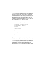
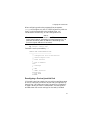
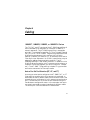
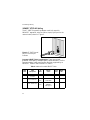
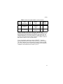
Allied Telesyn
Ethernet Network Adapter
For ISA Bus Computers and IEEE 802.3 Compliant LANs
Installation Manual
AT-1500T Plug and Play for Twisted Pair Media
AT-1500AT Plug and Play for AUI Port Adapter and Twisted Pair Media
AT-1500BT Plug and Play for Thinnet Coaxial and Twisted Pair Media
AT-1500FT Plug and Play for Fiber Optic and Twisted Pair Media
i
AT-1500 Plug and Play
Warranty: Your Allied Telesyn CentreCOM Ethernet Network Adapter has a lifetime
warranty. Refer to the warranty card supplied with the product for the full Warranty
Statement.
Trademarks: CentreCOM is a trademark of Allied Telesyn International Corp. Ethernet
is a registered trademark of Xerox Corporation. Novell and NetWare are registered
trademarks of Novell, Inc. Microsoft and MS-DOS are registered trademarks and LAN
Manager and Windows for Workgroups are trademarks of Microsoft Corporation.
UNIX is a registered trademark in the United States and other countries licensed
exclusively through X/Open Company Limited. 3Com is a registered trademark of
3Com. PC-NFS is a trademark of Sun Microsystems, Inc. PC/TCP is a registered
trademark of FTP Software, Inc.
©Copyright 1996 Allied Telesyn International Corp. (Allied Telesyn). All rights
reserved. No part of this publication may be reproduced without prior written
permission from Allied Telesyn.
Allied Telesyn reserves the right to make changes in specifications and other
information contained in this document without prior written notice. The information
provided herein is subject to change without notice. In no event shall Allied Telesyn
be liable for any incidental, special, indirect, or consequential damages whatsoever,
including but not limited to lost profits, arising out of or related to this manual or the
information contained herein, even if Allied Telesyn has been advised of, known, or
should have known, the possibility of such damages.
U.S. Federal Communications Commission
This equipment has been tested and found to comply with the limits for a
Class A digital device pursuant to Part 15 of the FCC Rules. These limits are
designed to provide reasonable protection against harmful interference when
the equipment is operated in a commercial environment. This equipment
generates, uses, and can radiate radio frequency energy and, if not installed
and used in accordance with this instruction manual, may cause harmful
interference to radio communications. Operation of this equipment in a
residential area is likely to cause harmful interference in which case the user
will be required to correct the interference at his own expense.
Canadian Department of Communications
This Class A digital apparatus meets all requirements of the Canadian InterferenceCausing Equipment Regulations.
Cet appariel numérique de la classe A respecte toutes les exigences du Règlement sur
le brouilleur du Canada.
All Countries: Install in accordance with Local and National Electrical Code.
ii
Contents
1
2
3
4
5
6
About the AT-1500 Plug and Play Adapter ............................................
The AT-1500 Package ......................................................................................
What Else You Need ........................................................................................
The Allied Telesyn CardAssistant .....................................................................
Installation ......................................................................................................
The Network Adapter Card ...............................................................................
The Plug and Play Difference ...........................................................................
Network Software and Driver Installation .........................................................
Installing the Card in an ISA or EISA Slot ........................................................
Support for Multiple Adapter Cards ..................................................................
Configuring with CardAssistant ...............................................................
Software Settings .............................................................................................
I/O Resources in Non Plug and Play Installation ..............................................
Full Duplex Operation .......................................................................................
Diagnostics Checks ..........................................................................................
Running CardAssistant in Command-Line Mode .............................................
Installing More than One Card ..........................................................................
Reconfiguring a Previously Installed Card ........................................................
Boot ROM Socket .............................................................................................
Cabling .............................................................................................................
10BASE-T, 10BASE2, 10BASE5, or 10BASE-FL Choices ..............................
Auto or Pre-Set Port Selection (BT, AT, and FT) .............................................
10BASE-T UTP/RJ45 Cabling ..........................................................................
10BASE2 RG58/BNC Cabling ..........................................................................
10BASE-FL/FOIRL (Optical Fiber) Connection ................................................
10BASE5 (AUI) Connection .............................................................................
Communication Status Indicators .....................................................................
Troubleshooting ............................................................................................
Identify the Exact Symptoms ............................................................................
Experiment with Possible Solutions ..................................................................
Manual/Adapter Card/CardAssistant/Driver Compatibility ................................
Get Technical Support ......................................................................................
Index .................................................................................................................
1
1
1
2
3
3
3
4
5
8
9
9
9
14
14
15
18
19
20
21
21
21
22
25
26
27
28
29
29
30
34
34
41
iii
AT-1500 Plug and Play
List of Figures
1
2
3
4
5
6
7
8
9
Configuration Dialog Box in Windows 95 Version of CardAssistant .................
AT-1500T Plug and Play UTP Port and RJ45 Connector ................................
Usable and Unusable 10BASE-T Cable............................................................
Pin 1 Orientation on an RJ45 Connector ..........................................................
BNC Receptacle for 10BASE2 (Shown Terminated) .......................................
Incorrectly Connected BNC for 10BASE2 ........................................................
ST-Type Connector for 10BASE-FL/FOIRL Media ..........................................
AUI Connector for Thicknet Drop Cable ...........................................................
AUI Connector for Direct Transceiver Connection ...........................................
12
22
24
24
25
25
26
27
27
List of Tables
1
2
3
4
5
6
7
8
9
iv
Which Driver to Use in a Workstation ...............................................................
Which Driver to Use in a Server, Bridge, Router, or Brouter ............................
I/O Configuration Settings ................................................................................
Command-Line Mode Parameter Names .........................................................
Parameter Order in Configuration Batch File ...................................................
Usable and Unusable 10BASE-T Cable ...........................................................
Allied Telesyn Micro Transceiver Choices .......................................................
AT-1500 Plug and Play Status Indicators .........................................................
Some Typical Device Uses of Bus Resources .................................................
4
5
13
16
18
22
28
28
32
Chapter 1
About the AT-1500 Plug and Play
Adapter
The Allied Telesyn AT-1500 Plug and Play Ethernet Adapter
Card is your PC’s link to a client/server or peer-to-peer Ethernet
Local Area Network (LAN). With your computer on the
network, you have access to a whole new world of computing.
The AT-1500 connects your computer to networked printers,
allows you to share files and data bases, and take advantage of
remote processing power and services like electronic mail and
Internet access.
The AT-1500 Package
When opening this Allied Telesyn product, make sure that the
package you have received is complete and in good condition. The
package includes:
❑ Ethernet network adapter card
❑ CardAssistant diskette
❑ Manual
What Else You Need
To use the Allied Telesyn AT-1500 Plug and Play card, you must
have access to an Ethernet network running network software
like Novell® NetWare®, Microsoft® Windows®NT, Sun®
PC-NFS, or Banyan® Vines.
To connect to the network, you will also need cables, connectors,
and terminators, depending on the Ethernet medium you use.
1
AT-1500 Plug and Play
Your computer must be an IBM-PC or compatible computer with
the following specifications:
❑ ISA bus (or EISA bus) computer with 16-bit slot available
that supports bus mastering
❑ Compatible operating system such as Windows 95,
Windows NT, Windows for Workgroups, Windows 3.x,
DOS, or OS/2
❑ Approximately 32K of available RAM, depending on the
driver installed
❑ 512K of available RAM when running Allied Telesyn
CardAssistant setup/diagnostics software
❑ A free 32-byte block of I/O between 220 and 3FF
❑ An available interrupt (IRQ 3, 4, 5, 9, 10, 11, 12, or 15)
❑ An available DMA channel (3, 5, 6, or 7)
The Allied Telesyn CardAssistant
The Allied Telesyn CardAssistant configuration and diagnostic
diskette has the software you need for setting up the
AT-1500 Plug and Play card with many different network
software packages. The diskette includes:
❑ CardAssistant setup and diagnostic test programs
Network adapter card drivers
• ODI drivers for use with a workstation on a Novell
NetWare network
• NDIS drivers for Microsoft Windows 95, Windows NT,
Windows for Workgroups, or TCP/IP
• A packet driver for TCP/IP
• ODI and NDIS drivers for servers.
❑ Support files for network software
❑ readme files
2
Chapter 2
Installation
The Network Adapter Card
The network adapter card may be considered to be a two-sided
device with one side talking to your computer and the other side
talking to the network. A special interpreter called the driver
allows your network to communicate with your computer. The
network adapter card uses an address, an interrupt request
number (an IRQ), and a direct memory access (DMA) channel
number to describe its logical location inside your PC. The
adapter card will work if:
❑ The adapter card has unique address(es), IRQ, and DMA
channel
❑ You have network software installed
❑ You have a driver installed for your particular network
software/network adapter card combination
❑ Your adapter card is properly connected to the network
The Plug and Play Difference
In a Plug and Play computer, the computer and the adapter card
work out the assignment of addresses, IRQs, and DMA channels
so that each accessory device has the unique resources that it
needs. Plug and Play capability is supplied by Windows 95, the
system BIOS, or third-party software such as Intel Plug and
Play Configuration Manager. To use this feature, check your
computer hardware and software manuals and make sure your
3
AT-1500 Plug and Play
computer is Plug and Play ready. In a non Plug and Play
situation, you may need to ensure that the card is configured to
work in your computer by resolving I/O resource settings.
Network Software and Driver Installation
Most of the network software manufacturers provide an
installation program that allows you to perform the entire
installation by making dialog-box choices. As part of the network
installation, the install script will prompt for the adapter card
driver files. The driver files for the AT-1500 adapter card are
found on the Allied Telesyn CardAssistant diskette, which you
will be called on to insert into a floppy drive.
Drivers for Workstations. Table 1 lists the drivers for use in a PC
workstation.
Table 1: Which Driver to Use in a Workstation
4
Network Software
Card Driver Path\Filename
Windows 95
\WINNT-95\AT1500M.SYS
NetWare for DOS
\DOS\AT15ODI.COM
NetWare Requester for OS/2
\OS2\AT1500.OS2
Personal NetWare
\DOS\AT15ODI.COM
Windows for Workgroups
\WFW31\AT1500.DOS
PC/TCP-compatible TCP/IP
\PKTDRV\AT1500.COM
Installation
Drivers for Servers. Table 2 shows the drivers for use in a server,
bridge, router, or brouter.
Table 2: Which Driver to Use in a Server, Bridge, Router, or Brouter
Network Software
Card Driver Path \Filename
Windows NT
\WINNT-95\AT1500M.SYS
NetWare v4.0
\NETWARE.40\AT1500.LAN
NetWare v3.11
\NETWARE.386\AT1500.LAN
NetWare v3.1
\NETWARE.386\AT1500.LAN
TIP: Network software manufacturers’ procedures and file
structures are subject to change. This is why the adapter
card manual can only provide general guidelines on
installing drivers. Additional, more up-to-date installation
notes may be found in the read.me file on the
CardAssistant diskette. Before beginning your network
software installation, print the file and note the driver name
and path.
Installing the Card in an ISA or EISA Slot
Once the driver is installed, complete the installation of the
network software, install the adapter card itself, and then reboot
the computer to load the driver files.
WARNING
High computer voltages present a safety hazard. Make sure
power is OFF before removing the cover.
5
AT-1500 Plug and Play
CAUTION
This LAN adapter card is for use only with IBM or compatible
UL listed personal computers that have installation
instructions detailing user installation of card-cage
accessories. Installation should be performed with precautions
to prevent damage to static-sensitive components.
NOTE
The AT-1500 Plug and Play card uses the bus-mastering
method for data transfers. Card slots 7 and 8 (often the two
right-most slots as viewed from the back of the computer)
often do not support bus mastering. Check your computer’s
manual.
1. Make sure the computer’s power is turned OFF.
TIP: When you install the AT-1500FT Plug and Play,
temporarily remove the shields from the fiber-optics cable
connectors to give the connectors more clearance.
2. Following the manufacturer’s instructions for adding a
card, install the AT-1500 in an expansion slot in your
computer. The slot should be a long ISA (16-bit) slot or an
EISA slot that supports bus mastering.
NOTE
If you are not using an EISA slot, skip step 3.
3. Run your computer’s EISA configuration utility and make
a note of the I/O resources (I/O Address Range, Interrupt
and DMA) available for the adapter card. Follow the EISA
utility instructions, and insert the Allied Telesyn
CardAssistant diskette when the EISA utility asks for the
“vendor diskette”.
6
Installation
In a non Plug and Play environment, the EISA utility asks
which I/O resources to reserve for the adapter card. You
can refer to Table 3 on page 13 and record the settings you
choose.
Installation example: Windows 95 workstation
1.
Turn your computer on and boot into Windows 95. Insert the ATI
CardAssistant diskette into the 3.5" diskette drive. If you wish to update the
driver that shipped with Windows 95 to the latest 32-bit version supplied
on the CardAssistant diskette,
•
On the Windows ToolBar, click the Start button.
•
Move the mouse to Programs, and then click MS-DOS Prompt on
the cascading menu.
•
In the Windows 95 home directory, change to the hidden INF
directory by typing:
cd INF
•
Save the current NETAMD.INF file by typing:
rename NETAMD.INF NETAMD.SAV
•
and copy the new information file to the Windows 95 INF directory by
typing:
copy <drive>:\WINNT-95\NETAMD.INF
where <drive> is the letter of the diskette drive containing the
2.
CardAssistant diskette.
With the CardAssistant diskette in the diskette drive, open CardAssistant
by typing:
<drive>:\CA
where <drive> is the letter of the diskette drive containing the
3.
4.
5.
6.
7.
CardAssistant diskette
Install the CardAssistant application by clicking Install CardAssistant on
the File menu.
Shutdown the computer, turn it off, and unplug it.
Install the adapter card by following the instructions that came with your
computer. See “Installing the Card in an ISA or EISA Slot” on page 5. Then
turn the computer on again.
Upon restarting your computer, Windows 95 finds the card you installed
and then prompts you for the driver.
With the CardAssistant diskette in the diskette drive, type the following
path in the dialog box:
<drive>:\WINNT-95
where <drive> is the drive letter of the floppy drive containing the
CardAssistant diskette. Windows 95 copies the driver and loads it.
7
AT-1500 Plug and Play
8.
9.
This completes the installation. To ensure that the network is accessible,
follow the procedures in How to make sure your card's installed correctly.
With the CardAssistant diskette in the diskette drive, type the following
path in the dialog box:
<drive>:\WINNT-95
where <drive> is the drive letter of the floppy drive containing the
CardAssistant diskette. Windows 95 copies the driver and loads it.
10. This completes the installation. To ensure that the network is accessible,
follow the procedures in How to make sure your card's installed correctly.
Installation note: NDIS for TCP/IP
AT1500.DOS is the AT-1500 Plug and Play adapter card driver based on the
Network Driver Interface Specification (NDIS) developed by Microsoft and 3Com.
It is used for implementations of Transmission Control Protocol/Internet Protocol
(TCP/IP) such as PC-NFS from Sun Microsystems.
AT1500.COM conforms to the Packet Driver specification developed by FTP
Software. It can be used for implementations of TCP/IP such as PC/TCP,
concurrent with other protocol stacks.
Although the Allied Telesyn drivers support multiple protocol stacks, it is important
to have only one stack of a given type resident. For example, if you use the public
domain IP protocol driver PROTMAN.SYS, you should not use another TCP/IP
stack concurrently.
More information on installing the NDIS driver and the packet driver in different
environments is available in the readme files on the CardAssistant diskette.
Support for Multiple Adapter Cards
You can have up to four AT-1500 Plug and Play adapter cards in
a single computer (workstation or server). Each needs its own
driver loaded (or the same driver loaded on a re-entrant basis).
Consult your network software documentation for instructions
on binding the drivers.
8
Chapter 3
Configuring with CardAssistant
Software Settings
If your computer does not have Plug and Play support, or if there
are non Plug and Play devices in the computer, you may need to
change settings for I/O resources used by the card. Instead of
hardware jumpers, the AT-1500 uses software settings to
configure the card. In a non Plug and Play or legacy
environment, the CardAssistant utility allows you to modify the
settings for the card. In a Plug and Play environment, the
settings you change with CardAssistant have no effect because
the computer takes over the assignment of I/O resources. It is
possible to turn off the Plug and Play capability if necessary to
resolve conflict with another device.
The CardAssistant program’s interactive mode lets you
configure the card from menus with your keyboard or mouse.
The command-line mode allows you to configure the card on a
DOS or OS/2 command line: (See “Running CardAssistant in
Command-Line Mode” on page 15).
I/O Resources in Non Plug and Play Installation
Before running CardAssistant to resolve I/O resource settings,
check the following conditions of card installation in conjunction
with your network-software and computer manuals.
1. Check system requirements on page 2.
9
AT-1500 Plug and Play
2. Consult your computer’s instruction manual for
information on adding peripherals.
3. Check I/O resources used by other peripherals.
TIP: If there is not another network card in the computer, the
default I/O settings are likely to work. Table 9 on page 32
lists some common conventions for ISA bus I/O.
4. Install the network software and driver. See “Network
Software and Driver Installation” on page 4.
5. Insert the card in the computer. See “Installing the Card in
an ISA or EISA Slot” on page 5.
6. Run the CardAssistant configuration program to check I/O
resource settings (base address, DMA channel, IRQ, boot
PROM address) and change as needed.
NOTE
Launching the CardAssistant program requires that the card
is present. If you have a driver running, you will not be allowed
to open the Diagnostics window.
Running CardAssistant in DOS Mode. The DOS version of
CardAssistant is the one to use if your primary operating system
is Windows 3.x, Windows for Workgroups 3.x, Windows NT 3.1,
or DOS.
1. Boot into DOS (not a Windows DOS Prompt window).
Prevent the driver from loading by pressing F5 to
bypass all batch and configuration files or F8 to step
through batch and configuration files and bypass lines that
load driver software.
2. If you are running CardAssistant from the installation
software diskette, follow steps 3 and 4. If CardAssistant is
installed on your hard disk, skip to step 5.
10
Configuring with CardAssistant
3. Insert the installation diskette into the appropriate floppy
drive.
4. Type: <drive>:setup15
where <drive> is the disk drive containing the
CardAssistant program. Proceed to step 6.
5. Install CardAssistant onto your hard disk by selecting the
Install command from the File menu. Once this is
accomplished, you can type:
path\setup15
where path\ is the optional drive and directory.
6. The main menu comes up and you are ready to select one of
the icons.
Running CardAssistant in 32-bit Windows Mode. If you are using
Windows 95 or Windows NT 3.5x, use this version of
CardAssistant.
1. If you are running CardAssistant from the installation
software diskette, follow steps 2 and 3. If CardAssistant is
installed on your hard disk, skip to step 4.
2. Insert the installation diskette into the appropriate floppy
drive.
3. Type: <drive>:ca
where <drive> is the disk drive containing the
CardAssistant program. Proceed to step 5.
4. Install CardAssistant onto your hard disk by selecting the
Install command from the File menu. Once this is
accomplished, you can type:
path\ca
where path\ is the optional drive and directory.
5. The main menu comes up and you are ready to select one of
the icons.
Working with CardAssistant Menus. You can use either the
keyboard or mouse to make menu selections, change settings,
and save or cancel your configuration changes.
11
AT-1500 Plug and Play
CardAssistant’s main menu presents you with the choice of
configuring the card or running diagnostics. Pop-up menus list
the possible resource settings, with the current setting
highlighted. The message window under the menu lists available
commands.
Changing AT-1500 Software Settings. If there are no other adapter
cards present in the computer, the likelihood of a conflict is
slight. In this case, use the Auto Configure option. If the
computer has other peripheral cards installed, you may need to
change one or more I/O settings. To help avoid conflicts, Table 9
on page 32 lists typical ways that devices are configured.
Figure 1: Configuration Dialog
Box in Windows 95 Version of
CardAssistant
12
Configuring with CardAssistant
1. Launch CardAssistant. If your primary operating system
is Windows 3.x, Windows for Workgroups 3.x, Windows
NT 3.1, or DOS, run the DOS version of CardAssistant. See
“Running CardAssistant in DOS Mode” on page 10. If your
primary operating system is Windows 95 or Windows NT
3.5x, run the 32-bit Windows version of CardAssistant. See
“Running CardAssistant in 32-bit Windows Mode” on
page 11.
2. Choose “Configure I/O Parameters” or “Auto Configure”
from the main menu. “Configure I/O Parameters” displays
the card’s current settings. “Auto Configure” proposes
settings for you. Check the settings that are proposed, and,
if necessary, select alternate settings from Table 3.
Table 3: I/O Configuration Settings
Resource
Default
Alternate Settings
Base I/O Address
300h
220h through 3E0h at 20h intervals
Interrupt Level
15
3, 4, 5, 9, 10, 11, 12
DMA Channel
7
3, 5, 6
Port Selection
Autoselect
UTP; optionally BNC, AUI, or Fiber
Plug and Play
Enabled
Disabled
Full Duplex
Disabled
Enabled
3. You can use the mouse or arrow keys to select the settings
to be modified.
4. Press ENTER and a pop-up menu displays the choices for the
resource you have selected.
5. When you have chosen the setting you want, press
ENTER
.
13
AT-1500 Plug and Play
6. When you are satisfied with the settings for all resources,
press F10 (DOS version) or Save configuration (32-bit
Windows version) to accept your changes. You do not have
to reboot the computer.
Full Duplex Operation
By default the card works in half duplex mode. In this mode, the
card can at a given time either send or receive data, but not both.
Clicking the full-duplex checkbox in the CardAssistant
Configuration dialog box changes the card’s capabilities to full
duplex which enables the card to send and receive
simultaneously. Full duplex operation is only effective if a fullduplex hub is at the other end of the Ethernet segment.
Diagnostics Checks
The CardAssistant diagnostic routines test the board and the
configuration for functional problems or conflicts with other
devices. The routines are:
• PC bus interface
• DMA channel
• Interrupt test
• Internal loopback
• Network Address
• Boot PROM (if applicable)
You can see if the board passes before connecting the computer
to the network, and then confirm that it still passes after the
network connector is plugged in. This method can help you
isolate any problem.
14
Configuring with CardAssistant
NOTE
Diagnostics runs in DOS mode with no drivers loaded.
comment out the driver line in the batch file (for NetWare) or
the DEVICE=drivername line in config.sys (for an NDIS
driver) and restart the PC.
1. Boot the computer into DOS. Launch CardAssistant by
typing:
<drive>:setup15 ENTER
where <drive> is the diskette drive containing the
CardAssistant program.
2. Select the Diagnostics menu by typing: d
ENTER
.
The diagnostic routines display whether the card passed each
test and report possible causes of any failures.
Running CardAssistant in Command-Line Mode
When you wish to prepare and configure several AT-1500 Plug
and Play cards for users in an assembly-line approach, you can
either use configuration parameters in the command line or you
can write a (.bat) file that invokes CardAssistant when read.
The syntax for running CardAssistant in batch mode (from DOS)
is as follows:
setup15 [IOBase]
[parameters]
where IOBase is the base hexadecimal I/O address of the adapter
(e.g., 300), and parameters is replaced with the parameters you
wish to modify from their default values. If you intend to use the
default value for a parameter, it may be omitted.
15
AT-1500 Plug and Play
Table 4 lists the parameters that may be set.
Table 4: Command-Line Mode Parameter Names
Parameter
Function
/Ix
x = interrupt level1
/Dx
x = DMA channel1
/UTP
selects the UTP (10BASE-T) port
/BNC
selects the BNC port
/FIBER
selects the Fiber Optic port
/AUI
selects the AUI port
/AUTO
configures for automatic port selection
/E
returns the number of AT-1500 Plug and Plays installed 2
/M
invokes CardAssistant in monochrome mode 2
/X
performs diagnostics2
/CWfilename
writes configuration file
/CRfilename
reads configuration file
NOTE 1. For the range of values, refer to Table 3 on page 13.
NOTE 2. Specialized parameter is used by itself.
With the exception of /CW, /CR, /E, /M, and /X, parameters may be
combined on the command line.
Here are sample command lines for differing requirements:
setup15 0x300 /I15 /D5 /UTP
setup15 320h /I5 /D6
/Fiber
setup15 /CRadapcard.prm
16
Configuring with CardAssistant
The /E parameter is a specialized switch that tells CardAssistant
to return the number of AT-1500 Plug and Play adapter cards
installed in the computer instead of executing the setup program.
This switch should be used on its own (i.e., without specifying
other parameters). One handy use is for a batch file that
determines which kind of card is installed and then loads the
right driver. For example, the following AUTOEXEC.BAT loads the
ODI driver for either an AT-1500 or an AT-1700:
SETUP17 -E
if ERRORLEVEL 1 goto AT1700_installed
SETUP15 -E
if ERRORLEVEL 1 goto AT1500_installed
echo NO ADAPTER IS INSTALLED!!!
goto done
:AT1700_installed
AT17ODI
goto done
:AT1500_installed
AT15ODI
goto done
:done
The /M parameter makes CardAssistant run in interactive mode,
but in monochrome. This switch should be used on its own.
The /X parameter is a specialized switch that tells CardAssistant
to perform diagnostic checks on the AT-1500 Plug and Play
adapter card installed in the computer instead of executing the
setup program. This switch should be used on its own (i.e.,
without specifying other parameters) and with no driver loaded.
17
AT-1500 Plug and Play
The /CR and /CW parameters are used instead of the commandline configuration switches to create a configuration file that
setup15 can use to configure subsequent cards. You use the /CW
switch to create a file from an adapter card and the
/CR switch to configure a card by reading the configuration from
the file. Alternatively, you can create a configuration file using a
text editor. This file is an ASCII file that must contain ALL
parameter values IN ORDER. The order is shown in Table 5.
Table 5: Parameter Order in Configuration Batch File
Parameter
Function
Board instance
The identifier of the adapter card being configured; the first
adapter card is 1
Base I/O
address
First address in hex of the I/O port
IRQ
Selected interrupt request line
DMA
Selected Direct Memory Access channel
Media
Selected Ethernet medium or AUTO SELECT
Boot ROM
Boot ROM address or DISABLE
Installing More than One Card
You can install up to four Allied Telesyn AT-1500 adapter cards
in the same computer, although a maximum of three is frequently
observed for speed/bus resource reasons. Each card requires its
own unique I/O resources (I/O port, IRQ, and DMA) and its own
driver loaded or the same driver loaded on a re-entrant basis. If
more than one card is installed in the host when you run
CardAssistant, the configuration window displays a column of
settings for each card. You can tell which column is for which
card by checking the node address. The displayed node address
agrees with the address label on the card itself.
18
Configuring with CardAssistant
When configuring cards using command-line parameters,
setup15 can configure only one AT-1500 Plug and Play card at a
time. If multiple boards are to be installed, either run
CardAssistant interactively, or use a configuration file.
NOTE
CardAssistant counts cards when it runs. This count correlates
to the “board instance” parameter in the configuration file. The
cards are counted by base I/O address in descending order
(from the highest address to the lowest).
e.g. "setup15 /CWfile.nam".
Comment lines are preceded by "//".
SAMPLE CARD CONFIGURATION FILE
-----------------------------//
// Configuration file for ATI AT-1500
// network adapter card
//
// Board instance
1
// Base IO Address
300h
// Interrupt
3
// DMA
6
// Media selection
Twisted Pair
// Boot PROM
DISABLE
Reconfiguring a Previously Installed Card
If the card is working properly but you wish to reconfigure some
of the I/O resources, you must first override the Plug and Play
feature. See “I/O Resources in Non Plug and Play Installation”
on page 9. When you launch CardAssistant, the configuration
window shows the current settings for the card(s) installed.
19
AT-1500 Plug and Play
If the card is not functioning correctly, the problem may be
caused by a configuration that conflicts with other accessories
installed in the workstation or server. In this case, refer to
“Troubleshooting,” Chapter 5.
Boot ROM Socket
The AT-1500 Plug and Play card is shipped with an unpopulated
boot ROM socket. For a diskless workstation, the card needs a
boot ROM to allow it to load the operating system over the
network. Because the boot ROM access is enabled by the
physical presence of the ROM, the boot ROM must be physically
removed to enable ROMless operation.
Boot ROMs are application-specific. Allied Telesyn supplies a
range of boot ROMs for different network environments.
Contact your Allied Telesyn representative for more
information.
20
Chapter 4
Cabling
10BASE-T, 10BASE2, 10BASE5, or 10BASE-FL Choices
The T, BT, AT, and FT versions of the AT-1500 Plug and Play all
have a shielded RJ45 receptacle for connection to 10BASE-T
network segments. The AT-1500 Plug and Play is compatible
with 100 Ω Unshielded Twisted Pair (UTP) or Shielded Twisted
Pair (STP) wire. The AT-1500AT Plug and Play supplements the
RJ45 with an Attachment Unit Interface (AUI) to which
10BASE2, 10BASE5, or 10BASE-FL, an extension of the earlier
Fiber Optic Inter-Repeater Link (FOIRL) specification, may be
adapted by adding the appropriate transceiver. The AT1500Plug and Play BT has a BNC connector—in addition to the
RJ45—for direct connection, with T-connector and terminator, to
a 10BASE2 Ethernet segment (thin wire Ethernet or “cheaper
net”). The AT-1500FT Plug and Play includes ST-type transmit
and receive connectors for fiber optic media.
Auto or Pre-Set Port Selection (BT, AT, and FT)
An auto port-select option configures the AT-1500BT, AT, or FT
Plug and Play to sense which of its two ports is connected. In
auto mode, the factory default mode, the card checks to see if the
twisted-pair port is connected. If not, it attempts to use the other
port. The alternative is to pre-set the port selection using the
CardAssistant configuration menu. In pre-set mode, both ports
can remain connected to network segments of different media.
The active port is the one selected in CardAssistant.
21
AT-1500 Plug and Play
10BASE-T UTP/RJ45 Cabling
The AT-1500T Plug and Play adapter card is for use with
10BASE-T segments, using an 8-wire (4-pair) RJ45 jack for the
network cable, shown in Figure 2.
Figure 2: AT-1500T Plug and
Play UTP Port and RJ45
Connector
Important 10BASE-T Cable Considerations. There are various
grades of voice-quality and data-quality cables available. The five
common modular cable specifications and their applicability to
10BASE-T network use are shown in Table 6.
Table 6: Usable and Unusable 10BASE-T Cable
Cable
Level
Cable
Description
AC
Char.
Specification
Twist/ 10BASE-T
Foot
OK?
1
Unshielded
untwisted
N/A
CCITT
none
NO!
2
Unshielded
Indv.Twisted Pairs
100 Ω
±30 Ω
RS232 1BASE5
AT&T PDS
none
NO!
3
Typ. Unshielded
Indv. Twisted Pairs
100 Ω
±15 Ω
TI, AT&T ISDN
10BASE-T
IBM Type 3
3-5
YES
22
Cabling
Table 6: Usable and Unusable 10BASE-T Cable (Continued)
Cable
Level
Cable
Description
AC
Char.
Specification
Twist/ 10BASE-T
Foot
OK?
4
Unshielded
Enhanced Indv.
Twisted Pairs
100 Ω
±30 Ω
EIA, TIA
10BASE-T
NEMA
5-8
YES
5
Shielded
Indv. Twisted Pairs
100 Ω
±30 Ω
EIA, TIA
10BASE-T
8-10
YES
These can appear to be similar externally, and their DC
characteristics are also similar, although their AC characteristics,
and therefore high-speed data transmission characteristics, are
radically different. As a rule of thumb, if a cable type is flat, it is
typically untwisted, and will cause problems. If a cable is more or
less round in section, it will typically work.
If any voice-quality cabling is used in a 10BASE-T network
system, data movement is slow, collision-prone, or non-existent.
The LNK indicator on the interface will usually indicate a valid
link in such a case. Be sure that all cabling used with the 10BASET adapter card connections is of level 3, 4, or 5.
23
AT-1500 Plug and Play
Check cable schematics against the ones shown in Figure 3.
Figure 3: Usable and Unusable 10BASE-T Cable
1
2
3
4
5
6
7
8
TD+
TDRD+
N/C
N/C
RDN/C
N/C
1
2
3
4
5
6
7
8
TD+
TDRD+
N/C
N/C
RDN/C
N/C
1
1
1. Pair twisted as per level 3, 4 or 5
cable
TD+
TDRD+
N/C
N/C
RDN/C
N/C
1
2
3
4
5
6
7
8
TD+
TDRD+
N/C
N/C
RDN/C
N/C
1
2
3
4
5
6
7
8
This cable will not work for
10BASE-T. Note that 3 and 6 are
twisted, but are not a pair.
Figure 4 shows where to find pin 1 on a standard RJ45.
Figure 4: Pin 1 Orientation on
24
Pin 1
Cabling
an RJ45 Connector
10BASE2 RG58/BNC Cabling
In addition to an RJ45 connector, the AT-1500BT Plug and Play
adapter has a BNC connector for 10BASE2 standard thin
Ethernet RG58 coaxial cable. The maximum segment length is
185 meters (606 ft.), and the minimum length between nodes is 0.5
meters (1.64 ft.). The coaxial cable should be connected to the
adapter card via a T-connector and must be terminated with a 50
Ω BNC terminator if the computer is at the end of a network
segment. See Figure 5. The connection must not be made as in
Figure 6.
Figure 5: BNC Receptacle for
10BASE2 (Shown Terminated)
Figure 6: Incorrectly
Connected BNC for 10BASE2
25
AT-1500 Plug and Play
10BASE-FL/FOIRL (Optical Fiber) Connection
The AT-1500FT Plug and Play provides both an RJ45 for
10BASE-T Ethernet and ST-type transmit and receive
connectors for 10BASE-FL or FOIRL Ethernet network
segments. Maximum segment length is 1000 meters (3279 ft.) for
FOIRL and 2000 meters (6558 ft.) for 10BASE-FL. (See
Figure 7.)
NOTE
Hazardous light emissions may exist in fiber optic systems.
Severe eye damage may result if precautions are not taken.
Never look into a transmitting fiber optic device, transceiver,
repeater, or cable.
In a 10BASE-FL or FOIRL segment, the cables connect the
transmit receptacle at one end of the segment to the receive
receptacle at the other end and vice versa.
Figure 7: ST-Type Connector
for 10BASE-FL/FOIRL Media
26
Cabling
10BASE5 (AUI) Connection
The AT-1500AT Plug and Play adapter offers both an RJ45 and an
AUI port. (See Figure 8 and Figure 9.)
Figure 8: AUI Connector for
Thicknet Drop Cable
Figure 9: AUI Connector for
Direct Transceiver Connection
In Figure 8, you see a drop cable from a remote transceiver,
typically on a thicknet backbone. In Figure 9, you see the
transceiver installed directly on the AUI port. Installing the
appropriate Allied Telesyn transceiver from Table 7 on the AUI
port allows you to interface with the medium of your choice.
27
AT-1500 Plug and Play
Table 7: Allied Telesyn Micro Transceiver Choices
Model
Description
AT-MX25F/AT-MX26F
Fiber Optic (FOIRL, 10BASE-FL)
AT-210T/AT-210TS/
AT-MX20T
UTP (10BASE-T)
AT-MX10/AT-MX10S
Thin Ethernet (10BASE2)
If a transceiver is installed, care must be taken with the setting of
the heartbeat/SQE switch. Unless the transceiver is installed on a
device that specifically requests that the heartbeat/SQE switch
be ON, this switch should be set to OFF. Failure to set the
heartbeat/SQE switch correctly results in degradation or failure
of network communication.
Communication Status Indicators
Table 8 shows the functions of the four status indicators located
above the RJ45 receptacle.
Table 8: AT-1500 Plug and Play Status Indicators
LED Color
Label
Indicates
Used by
Green
Yellow
Green
TX
RX
LNK
Transmitting packet
Receiving packet
Valid receive link signal
Yellow
COL
Collision detected
All media
All media
10BASE-T,
10BASE-FL
All media
28
Chapter 5
Troubleshooting
A network is a complex combination of hardware and software,
all of which must function for data communication to work.
Problems are most likely to occur when the card is first being
installed or when someone changes something in the network. A
problem could be caused in your computer or in cabling or in
many places elsewhere in the network.
If your computer is supported by a system administrator or
network administrator, this person can often provide the most
help in resolving a problem. Allied Telesyn dealers also provide
technical support for installation problems. But if one of these
local resources is not successful solving your problem, you can
obtain assistance directly from Allied Telesyn by fax or by
telephone. See “Where To Find Us” on page 35.
Identify the Exact Symptoms
If your computer is unable to communicate across the network,
carefully observe the symptoms. Gather information about the
system and its components, such as device drivers, memory and
extensions (e.g., QEMM), other peripheral cards and the use of
I/O ports, IRQs, and DMA channels. Log your interaction with
the computer, noting the conditions, your actions and the
responses. Analyzing this information will help you diagnose the
cause of the failure.
29
AT-1500 Plug and Play
Experiment with Possible Solutions
This chapter provides the common factors to check in
troubleshooting. It is by no means exhaustive since there are too
many environmental factors to take into account.
The first rule of troubleshooting is to isolate the problem. As you
experiment, vary only one factor at a time. Substitute known
good equipment and see if the problem persists or is eliminated.
❑ Do not overlook the obvious—make sure the card is seated
in the computer and that the cables and connectors are
securely attached.
❑ If the LNK indicator does not light with UTP or fiber
media, make sure the cabling is intact and connected to a
functioning network port.
❑ If the LNK indicator lights on a 10BASE-T segment, but
data transfer is slow, collision-prone, or non-existent, verify
that your cable is of level 3, 4, or 5 (see Chapter 7, Important
10BASE-T Cable Considerations). Level 1 and 2 voicequality cable will not work properly.
If the cable is more or less round in section, you probably
have data grade cable, correctly paired, and no transmission
problems. If, however, the cable appears flat in section (as
“Silver Satin” telephone-type cable) you probably have
voice-grade cable and transmission problems. If it looks like
telephone cable, double-check it.
❑
If the computer is on a 10BASE2 segment, make sure the
cable is connected with T-connectors, terminated at the
ends with 50 Ω terminators, and grounded in only one place.
❑ If you suspect the network adapter card is not working
properly, disconnect the computer from the network and
run CardAssistant diagnostics after rebooting with no
drivers loaded.
30
Troubleshooting
❑ If CardAssistant software does not detect the card, it could
mean a conflict between the card and another device, a card
failure or a slot failure. You may need to reconfigure the
adapter card or the other device to avoid the conflict.
Only one device in the computer can use each I/O port, DMA
channel and interrupt vector. If two (or more) devices try to
share resources, one or all do not function properly. Table 9 lists
common uses of resources that can cause conflict.
To correct an I/O resource conflict
NOTE
High voltages inside the computer present a safety hazard. Be
sure the power is OFF before removing the cover.
NOTE
Remove the card at a static-free workstation, taking
precautions to prevent damage to static-sensitive components.
1. Remove the card from the computer according to the
manufacturer’s reference manual.
2. Move the card to another computer. See “Installing the
Card in an ISA or EISA Slot” on page 5.
3. Launch CardAssistant (page 10) and run diagnostics again
(page 14).
4. If diagnostics passes, change the adapter card
configuration (page 9), and move the card back to the target
computer.
5. Update the adapter card driver for the new settings. (See
your network software manual.)
31
AT-1500 Plug and Play
Table 9: Some Typical Device Uses of Bus Resources
This
resource...
may be used for...
Base I/O Address
200h-21Fh
Games I/O
220-23Fh
Mouse
260h-27Fh
IDE controller, LPT2
2E0h-2FFh
Serial port 4, serial port 2
300h-31Fh
Prototyping board; network adapter card
360h-37Fh
LPT1
380h-39Fh
SDLC; secondary bi-synch interface
3A0h-3BFh
Monochrome display and parallel printer port
3EOh-3FFh
Serial port 3, diskette controller, serial port 1
IRQ
32
NMI
Parity errors
0
System timer
1
Keyboard
2
Cascade input for second interrupt controller
3
COM2
4
COM1
5
LPT2
6
Disk controller
Troubleshooting
Table 9: Some Typical Device Uses of Bus Resources (Continued)
This
resource...
may be used for...
7
LPT1; data acquisition, voice comm. adapter
8
Real-time clock interrupt
9
EGA/VGA
10
Reserved
11
Reserved
12
Reserved
13
Coprocessor
14
Hard disk controller
15
Reserved
To determine base I/O address and interrupt
If the CardAssistant program does not detect the presence of the
card, the address may be in a range that conflicts with another
device on the bus. In this case, the only way to access the card is
to change the base address setting of one device or the other.
Either remove other card-cage peripherals that might have the
same I/O address or move the AT-1500 Plug and Play to another
computer.
If the card passes diagnostics, try reconnecting the computer to
the network and running diagnostics again. This time a failure
may be caused by physical medium connections or by corrupted
network software. You can test the connectors, terminators and
cables by swapping them for known good ones.
33
AT-1500 Plug and Play
To replace corrupted network software
1. Temporarily move the files that refer to the adapter card
driver and comment out references in your batch files.
2. Refer to your LAN administration manual for instructions
on how to install your network software.
Manual/Adapter Card/CardAssistant/Driver Compatibility
This manual is intended for use only with the AT-1500 Plug and
Play 8-interrupt jumperless adapter cards with which it was
shipped. The manual will incorrectly reflect the use of earlier
adapter cards.
The Version 2.2 CardAssistant software and card drivers
shipped with this manual are backward-compatible with respect
to the AT-1500 Plug and Play adapter card, and will operate
correctly with earlier versions of that card.
Get Technical Support
You can contact the dealer where you bought your AT-1500 Plug
and Play for local assistance. If local help is unable to resolve
your problem, Allied Telesyn offers technical support via fax or
telephone. In North America, support engineers are available
between the hours of 6:30 a.m. and 5 p.m. Pacific time.
Please call the support office for your region. See “Where To
Find Us” on page 35. The voice and fax telephone numbers for
technical support are listed for each regional office.
34
Troubleshooting
Where To Find Us
For Technical Support or Service
Location
Phone
Fax
North America
United States, Canada, Mexico, Central America,
South America, Australia, New Zealand
1 (800) 428-4835
1 (206) 481-3790
France
France, Belgium, Luxembourg, The Netherlands,
Middle East, Africa
(+33) 1-69-28-16-17
(+33) 1-69-28-37-49
Germany
Germany, Switzerland, Austria, Eastern Europe
(+01) 30-83-56-66
(+49) 30-435-70-650
Italy
Italy, Spain, Portugal, Greece, Turkey, Israel
(+39) 2-38093-444
(+39) 2-38093-448
United Kingdom
United Kingdom, Denmark, Norway, Sweden,
Finland, Iceland
(+0) 800-20-40-40
(+44) 1-865-390-002
Japan
(+81) 3-3443-5640
(+81) 3-3443-2443
Asia
Singapore, Taiwan, Thailand, Malaysia, Indonesia,
Korea, Philippines, China, India
(+65) 383-2050
(+65) 383-2079
Hong Kong
(+852) 2-529-4111
(+852) 2-529-7661
Technical Bulletin Board Service
1 (206) 483-7979
CompuServe
Internet
World Wide Web
Go ALLIED
ftp://gateway.centre.com
http://www.alliedtelesyn.com
35
AT-1500 Plug and Play
For Information Regarding Allied Telesyn International Corp.
Allied Telesyn International Corp.
19015 North Creek Parkway Suite 200
Bothell, WA 98011
Tel: 1 (206) 487-8880
Fax: 1 (206) 489-9191
Allied Telesyn International Corp.
950 Kifer Road
Sunnyvale, CA 94086
Tel: 1 (800) 424-4284 (USA and Canada)
Fax: 1 (408) 736-0100
For Sales Information
United States
The Netherlands
Lilburn, GA
Tel: (404) 717-0290, Fax: (404) 717-0806
Salt Lake City, UT
Tel: (801) 350-9130, Fax: (801) 350-9051
Portsmouth, NH
Tel: (603) 382-0815, Fax: (603) 382-0818
Vienna, VA
Tel: (703) 506-0196, Fax: (703) 506-1986
Chicago, IL
Tel: (708) 406-8431, Fax: (708) 406-8462
Austin, TX
Tel: (512) 502-3087, Fax: (512) 794-9326
Dallas, TX
Tel: (214) 446-9873, Fax: (214) 446-8555
Reading, MA
Tel & Fax: (617) 944-3492
Los Angeles, CA
Tel: (310) 412-8684, Fax: (310) 412-8685
Costa Mesa, CA
Tel: (714) 432-6424, Fax: (714) 432-6546
San Diego, CA
Tel: (619) 279-3896, Fax: (619) 279-3897
Clearwater, FL
Tel: (813) 726-0022, Fax: (813) 726-0234
Tunnersville, NJ
Tel: (609) 468-1070, Fax: (609) 468--1201
Schiphol
Tel: (+31) 20-654-0111, Fax: (+31) 20-654-0270
Canada
Shinagawa-ku, Tokyo
Tel: (+81) 3-3443-5640, Fax: (+81) 3-3443-2443
Yodogawa-ku, Osaka
Tel: (+81) 6-391-6310, Fax: (+81) 6-391-6325
Fujisawa-shi, Kanagawa
Tel: (+81) 466-88-8510, Fax: (+81) 466-88-8515
Machida-shi, Tokyo
Tel: (+81) 427-21-8141, Fax: (+81) 427-21-8848
Nagoya-shi, Aichi
Tel: (+81) 52-223-3791, Fax: (+81) 52-223-3736
Nagoya-shi, Aichi
Tel: 81 52 223 3791, Fax: 81 52 223 3736
Mississauga, Ontario
Tel: (905) 803-8626, Fax: (905) 279-0050
Richmond, British Columbia
Tel: (604) 244-0678, Fax: (604) 270-3644
Germany
Berlin
Tel: (+49) 30-435-9000, Fax: (+49) 30-435-70650
Freising
Tel: (+49) 8161-62-002, Fax: (+49) 8161-68-374
36
Italy
Milano
Tel: (+39) 2-38093-444, Fax: (+39) 2-38093-448
England
Abingdon, Oxon
Tel: (+1) 44-865-390001, Fax: (+1) 44-865-390002
France
Les Ulis
Tel: (+33) 1-69-28-16-17, Fax: (+33) 1-69-28-37-49
Hong Kong
Kowloon
Tel: (+852) 2-393-0101, Fax: (+852) 2-397-7979
Wanchai
Tel: (+852) 2-529-4111, Fax: (+852) 2-529-7661
Singapore
Tel: (+65) 383-3832, Fax: (+65) 383-3830
Japan
Software License Agreement
PLEASE READ THIS SOFTWARE LICENSE AGREEMENT COMPLETELY. BY USING THE SOFTWARE, YOU AGREE TO BE
BOUND BY THE TERMS OF THIS LICENSE. IF YOU DO NOT AGREE TO THESE TERMS, PROMPTLY RETURN THE UNUSED
SOFTWARE TO THE PLACE WHERE YOU OBTAINED IT AND YOUR MONEY WILL BE REFUNDED.
1. Definitions. “Software” means software delivered on floppy disk or downloaded over a network from an on-line bulletin
board, and any firmware object programs included or provided for use with Equipment in any machine-readable or
interpreted form; and includes authorized copies and any software or firmware updates. “Equipment” means the Allied
Telesyn International Corp. (Allied Telesyn) communications hardware products with which Software delivered in firmware
is obtained. “Product” includes Allied Telesyn Equipment and firmware-based Software in such Equipment.
2. License. Allied Telesyn and its licensors retain ownership of the Software. For Software delivered on floppy disk, you own
the disk on which the Software is recorded. For Software delivered on floppy disk or downloaded from a bulletin board, you
are granted a non-exclusive license to use the Software on a single computer and to make one backup copy of the Software
in machine-readable form. You must reproduce on the backup copy all copyright and other proprietary legends appearing
on the original copy of the Software. For Software delivered in firmware, you are granted a non-exclusive license to use the
Software solely on the Equipment with which it is delivered, or in the case of updates, for which it is provided.
3. Transfer. You may transfer all of your license rights in the Software, along with any backup copy and all associated
documentation, to another party, provided you give that party a copy of this License and such party reads and agrees to the
terms of this License. Software delivered in firmware may be transferred only when title to the associated Equipment is
transferred to the same party.
4. Restrictions. The Software contains copyrighted material, trade secrets and other proprietary material. You may not
decompile, reverse engineer, disassemble, translate or otherwise reduce the Software to human-perceivable form. You may
not rent, lease, loan, sublicense, disclose, distribute, modify or create derivative works based upon the Software in whole
or in part.
5. Limited Warranty. For Software delivered on disk, Allied Telesyn warrants that the disk on which the Software is recorded
will be free from defects in materials and workmanship under normal use for ninety (90) days from the date of purchase.
All Software is provided AS IS and without any warranty of any kind, except that for Software delivered in firmware, Allied
Telesyn warrants that the Software will meet Allied Telesyn’s published specification during the warranty period for the
associated Equipment.
For purposes of the remainder of this section and section 6, “Allied Telesyn” includes Allied Telesyn and its licensors, if any.
For Software delivered on disk, Allied Telesyn’s entire liability and your exclusive remedy will be replacement during the
warranty period of a disk not meeting the warranty. You may return a defective disk to Allied Telesyn International Corp.
(Allied Telesyn). For Software delivered in firmware, Allied Telesyn’s entire liability and your exclusive remedy will be, at
Allied Telesyn’s option, the repair or replacement during the warranty period of a Product not meeting the warranty, or the
refund of the price paid for the Product (upon return of the Product). THESE WARRANTIES ARE IN LIEU OF ALL OTHER
WARRANTIES, EXPRESS OR IMPLIED, INCLUDING ANY IMPLIED WARRANTIES OF MERCHANTABILITY, FITNESS FOR
PARTICULAR PURPOSE OR NON-INFRINGEMENT OF THIRD PARTY RIGHTS. Allied Telesyn DOES NOT WARRANT THAT
THE SOFTWARE OR DOCUMENTATION WILL MEET YOUR REQUIREMENTS OR BE ERROR FREE OR THAT THE
OPERATION OF THE SOFTWARE WILL BE UNINTERRUPTED, OR THAT DEFECTS IN THE SOFTWARE AND
DOCUMENTATION WILL BE CORRECTED. NO WRITTEN OR ORAL information or ADVICE GIVEN BY Allied Telesyn OR AN
Allied Telesyn RESELLER or distributor WIll create ANY WARRANTY or in any way increase the scope of this warranty. This
warranty gives you specific legal rights. You may have other rights that vary from state to state and country to country.
SOME STATES DO NOT ALLOW THE EXCLUSION OF IMPLIED WARRANTIES, SO THE ABOVE EXCLUSION MAY NOT
APPLY TO YOU. ANY IMPLIED WARRANTIES ARE LIMITED IN DURATION TO NINETY (90) DAYS.
6. Limitation on Liability. UNDER NO CIRCUMSTANCES WILL Allied Telesyn BE LIABLE FOR ANY INCIDENTAL, SPECIAL
OR CONSEQUENTIAL DAMAGES OR FOR LOST PROFITS OR LOST SAVINGS RESULTING FROM THE USE OF OR
INABILITY TO USE THE SOFTWARE OR RELATED DOCUMENTATION, EVEN IF Allied Telesyn HAS BEEN INFORMED OF THE
POSSIBILITY OF SUCH DAMAGES. Some states do not allow the limitation or exclusion of liability for incidental or
consequential damages, so the above limitation or exclusion may not apply to you.
In no event will Allied Telesyn’s total liability to you for all damages, losses and causes of action, whether in contract, tort
(including negligence) or otherwise, exceed the amount paid by you for the Software.
7. Export. Export or re-export of Software or any technical data received from Allied Telesyn, and any direct product thereof,
may be subject to U.S. or other government restrictions. You agree to comply with all applicable government export
regulations.
37
AT-1500 Plug and Play
8. Government End Users. If you are accepting the Software on behalf of any unit or agency of the United States
Government, the following provisions apply. The Government agrees: (i) if the Software is supplied to the Department of
Defense (DoD), the Software is classified as “Commercial Computer Software” and the Government is acquiring only
“restricted rights” in the Software and documentation as that term is defined in Clause 252.227-7013(c)(1) of the DFARs;
and (ii) if the Software is supplied to any other unit or agency of the United States Government, the Government’s rights in
the Software and documentation are defined in Clause 52.227-19(C)(2) of the FAR or, in the case of NASA, in Clause 1852.227-86(d) of the NASA Supplement to the FAR. Contractor/manufacturer is Allied Telesyn International Corp., 575 E.
Middlefield Road, Mountain View, California.
9. Dual Media. If Software is supplied on both 3.5 inch and 5.25 inch disks, then you may use only the disk that is
appropriate for the one computer with which you will use the Software. You may not use, nor permit anyone else to use,
the other disk, except as part of the transfer of all of your rights in the Software.
10. Termination. This License will terminate immediately without notice if you fail to comply with any provision of this
License.
11. General. This License will be governed by the laws of the United States and of California, as applied to agreements
entered into by California residents and performed within California. If any Software is to be used outside the United States,
the rights and obligations under this License will not be governed by the United Nations Convention on Contracts for the
International Sale of Goods, the application of which is expressly excluded. If for any reason a court finds any provision of
this License, or any portion thereof, to be unenforceable, that provision will be enforced to the maximum extent permissible,
and the remainder of this License will continue in full force and effect. This License constitutes the entire agreement between
the parties with respect to the Software and related documentation, and supersedes all prior or contemporaneous
understandings or agreements. No amendment or modification of this License will be binding unless in writing and signed
by an officer of Allied Telesyn.
38
Adapter Card Revision History
Revision Description
Date
Added boot ROM support
4/93
Changed layout of the AT-1500 Plug and PlayT
jumpers
8/93
Added AUI port option
8/93
Converted to high/low interrupt-request (IRQ)
options
8/93
Converted to 8-interrupt (IRQ) selection
1/94
Added updated drivers. Upgraded Ethernet
Controller
2/95
Added support for Plug and Play
5/95
Added updated drivers. Added 32-bit Windows Setup
11/95
39
AT-1500 Plug and Play
Adapter Card Manual Feedback
We would like you to tell us the type of additional information you would like to see
in the manual. If there are topics you want to be covered in the manual, please
photocopy this page, answer the questions and fax or mail this information. The
mailing address is at the bottom of the page. Your comments are valuable when we
plan future revisions of the manual.
On a scale of 1 to 10 (10 being most important), my uses of the manual information
are:
CardAssistant Installation
Diagnostics
Batch Configuration
Multiple Cards Installation
Driver Installation
Driver Selection
______
______
______
______
______
______
CardAssistant Operation
Card I/O Configuration
Troubleshooting
Network Software
Adapter Card Operation
Cabling
______
______
______
______
______
______
I found the following the most valuable _________________________________
_______________________________________________________________
_______________________________________________________________
I would like the following more developed _______________________________
_______________________________________________________________
_______________________________________________________________
I would find the manual more useful if__________________________________
_______________________________________________________________
_______________________________________________________________
Please fax or mail your feedback. Fax to 1-206-481-3790. Or mail to:
Allied Telesyn
Technical Publications Department
19015 North Creek Parkway, Suite 200
Bothell, WA 98011 USA
40