1
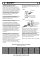
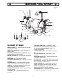
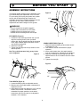
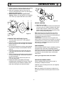
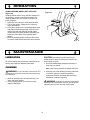
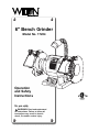
6" Bench Grinder
Model No. 17204
6" BENC
H GRIN
Operation
and Safety
Instructions
For your safety
WARNING: Read and understand
all instructions. Failure to follow all
instructions may result in electric
shock, fire and/or serious injury.
DER
IMPORTANT INFORMATION
INTRODUCTION
SPECIFICATIONS
Your 6" Bench Grinder is a dependable tool that is
designed for hand-grinding operations such as
sharpening chisels, screwdrivers, drill bits, removing
excess metal, and smoothing metal surfaces. Easy to
operate, it’s the ideal bench grinder for the serious
Do-It-Yourselfer.
Model Number ................................................. 17204
Power Source.....................................120V AC, 60 Hz
Maximum developed horsepower .....................1/2 Hp
Amps .......................................................................2.8
Speed ..........................................3450 RPM (no load)
Wheel size ....................................6" x 3/4", 1/2" arbor
Wire brush ...............................6" dia, 1/2" - 5/8" arbor
Lamp.............................Automotive type 12 V, 6 Watt,
single contact bayonet
Tool rests ................................................Right and left
Eye shields .............................................Right and left
Spark arrestors .......................................Right and left
Net weight ........................................24.1 lbs (10.9 kg)
Please take time to read this Instruction Manual
thoroughly. Pay attention to all safety rules. A
thorough understanding of your bench grinder will
enable you to use it to its full potential.
LIMITED WARRANTY
Wilton Power Tools are warranted against defects in workmanship and material for a period of two (2) years from the date of purchase.
This warranty does not cover defects due directly or indirectly to misuse, abuse, negligence or accidents, normal wear-and-tear,
improper repair or alterations, lack of maintenance, or use for purposes other than those for which the tool was designed. This
warranty does not cover products used for commercial, industrial or educational purposes. Any return must be preauthorized, so please
contact our Consumer Relations Department with warranty claims at 1-800-274-6848 for further instructions. If it is determined that the
product is within this warranty, replacement parts or complete product replacement will be made at our discretion.
WMH TOOL GROUPTM LIMITS ALL IMPLIED WARRANTIES TO THE PERIOD OF THE LIMITED WARRANTY FOR EACH PRODUCT.
EXCEPT AS STATED HEREIN, ANY IMPLIED WARRANTIES OF MERCHANTABILITY AND FITNESS ARE EXCLUDED. SOME
STATES DO NOT ALLOW LIMITATIONS ON HOW LONG THE IMPLIED WARRANTY LASTS, SO THE ABOVE LIMITATION MAY
NOT APPLY TO YOU.
WMH TOOL GROUPTM SHALL IN NO EVENT BE LIABLE FOR DEATH, INJURIES TO PERSONS OR PROPERTY, OR FOR
INCIDENTAL, CONTINGENT, SPECIAL, OR CONSEQUENTIAL DAMAGES ARISING FROM THE USE OF OUR PRODUCTS. SOME
STATES DO NOT ALLOW THE EXCLUSION OR LIMITATIONS OF INCIDENTAL OR CONSEQUENTIAL DAMAGES, SO THE ABOVE
LIMITATION OR EXCLUSION MAY NOT APPLY TO YOU.
TABLE OF CONTENTS
IMPORTANT INFORMATION ....................................2
Introduction ..........................................................2
Specifications.......................................................2
LIMITED WARRANTY ...............................................2
SAFETY .....................................................................3
General Safety Warnings.....................................3
Special Safety Rules for Bench Grinders ............4
Electrical Requirements.......................................5
BEFORE YOU START...............................................7
Glossary of Terms................................................7
Unpacking Your Bench Grinder ...........................8
Assembly Instructions..........................................9
OPERATION ............................................................10
Light ...................................................................10
Mounting the Grinder .........................................10
Changing the Grinding Wheel ...........................10
Changing the Light Bulb ....................................11
Before Grinding..................................................11
When Grinding ...................................................11
Reshaping Grinding Wheel ................................11
Using Dressing Wheel .......................................12
MAINTENANCE.......................................................12
Lubrication .........................................................12
Cleaning.............................................................12
TROUBLESHOOTING.............................................13
SERVICE..................................................................14
2
SAFETY
Wear the Proper Apparel – and nonslip footwear
when operating power tools. Do not wear loose
clothing, gloves, neckties, rings, bracelets or other
jewelry which may become caught in moving parts.
Keep long hair away from your face and tied back. Roll
long sleeves above the elbow.
Read, understand and follow all operating instructions,
safety operations and symbols in this manual before
operating and maintaining your power tool.
WARNING: Indicates the presence of a hazardous
situation which CAN cause SEVERE personal injury.
Use Safety Goggles at all
Times – which comply with
ANSI Z87.1. Normal safety
glasses only have impact
resistant lenses and are not
designed for safety. Wear a
face or dust mask when
working in a dusty environment. Use ear protection,
such as plugs or muffs, during extended periods of
operation.
CAUTION: Indicates the presence of a hazardous situation
which WILL or CAN cause MINOR or MODERATE PERSONAL
injury, or could cause machine damage.
Note: Indicates installation, operation or maintenance
information which is important but not hazard-related.
GENERAL SAFETY WARNINGS
WARNING: Failure to read all instructions and follow the
general safety warnings and other safety warnings and cautions
may result in serious personal injury.
Wear a Face Mask or Dust Mask – when the grinding
operation produces dust.
Secure Your Work – using clamps or a vise when
practical. It frees both hands and is safer to operate
the tool.
Know Your Power Tool – read the instruction manual.
Understand your power tool’s application, limitations
and potential hazards.
Don’t Overreach – and keep proper balance and
footing at all times.
Ground All Tools – this tool is equipped with a
3-prong plug, it must be plugged into a 3-contact
electric outlet. The 3rd prong is a ground to provide
protection against accidental electric shock. Never
remove the 3rd prong on a grounded plug.
Maintain Your Tools with Care – keeping them clean
for best and safest performance.
Disconnect Your Tool – by unplugging the power
cord from the electrical outlet when making
adjustments, changing parts, cleaning, or working on
the tool.
Keep Safety Guards in Place – and working order
with proper adjustment and alignment.
Keep Work Area Clean – to help prevent accidents.
Take time to clean the tool, work area and especially
the floor. The floor can become slippery from sawdust,
wax and other materials.
Avoid Accidental Starting – by ensuring the switch is
in the OFF position and the power cord is unplugged
from the electrical outlet.
Use the Recommended Accessories – by the tool’s
manufacturer. Refer to this instruction manual for
approved accessories. Read, understand and follow
the instructions supplied with accessories. Using
incorrect accessories may be hazardous.
Avoid Dangerous Environments – by not using
power tools in damp, wet or raining environments.
Provide an adequate work area that is properly
illuminated.
Keep Children Away – from the work area. Children
and others should be a safe distance from the work
area.
Never Stand on the Tool – or store materials above
or near it. Standing on the tool to reach materials could
result in serious injury if it tips or is accidentally
contacted.
Make the Workshop Childproof – by using padlocks,
master switches and removing starter keys from power
tools.
Check any Damaged Parts – and discontinue using a
damaged tool until the part is carefully checked.
Ensure that all parts will operate and perform properly.
Check for alignment of moving parts, binding of
moving parts, breakage of parts, mounting and any
other conditions that may affect its operation. A guard
or other part that is damaged should be properly
repaired or replaced before using the tool.
Don’t Force the Tool – beyond its designed rate. For
a better and safer job, allow the tool to work within
manufacturer’s recommendation.
Use the Right Tool – for the job. Do not force a tool or
its attachments to perform a task that it’s not designed
to do.
SAVE THESE SAFETY INSTRUCTIONS
3
SAFETY
Never Leave the Tool Unattended While it’s
Running – turn OFF the power. Do not leave the tool
unattended until it reaches a complete stop.
Only wear safety goggles that comply with
ANSI Z87.1
The operation of any
grinder can result in foreign
objects being thrown into
your eyes, which can result
in severe eye damage.
● Glasses or goggles that are
not in compliance with ANSI
Z87.1 could break resulting in severe eye injury.
Wear a face or dust mask when working in a dusty
environment.
● Use ear protection, plugs or muffs, during extended
periods of operation.
Always use tool guards and eye shields provided
with the grinder, safety goggles or other eye
protection. Keep your thumbs and fingers away from
the wheel.
●
Drugs, Alcohol, Medication – are not to be used
when operating the tool.
Some dust created by power sanding, sawing,
grinding, drilling, and other construction activities
contain chemicals known to cause cancer, birth
defects or other reproductive harm. Some examples
of these chemicals are:
– Lead from lead-based paints,
– Crystalline silica from bricks, cement, and other
masonry products, and
– Arsenic and chromium from chemically treated
lumber.
To reduce your exposure to these chemicals: work in
a well-ventilated area, use approved safety
equipment, and use dust masks that are specially
designed to filter out microscopic particles.
Replace a cracked grinding wheel immediately.
A cracked wheel can throw pieces at a high velocity.
Handle wheels carefully; before replacing a wheel,
check it for cracks. Tighten the spindle nut just enough
to hold the wheel firmly: if the nut is tightened too
much, the clamping strain can damage the wheel.
Use only wheel flanges provided with grinder. When
selecting a replacement wheel, be sure that the grinder
will not exceed the manufacturer's recommended
speed (RPMs) for the wheel.
SPECIAL SAFETY RULES FOR
BENCH GRINDERS
WARNING: Do not operate your bench grinder until it
is assembled, and you have read and understand the following
instructions and the warning labels on the bench grinder.
Before Operating Your Bench Grinder
Check for proper assembly and proper alignment of
moving parts.
The diameter of the grinding wheel decreases
with use. Adjust tool rests to maintain a distance of
1/16" or less from the wheel. Also keep the distance
between the spark arrestor and grinding wheel 1/8"
or less.
Understand the function and proper use of:
●
●
Eye shields
Tool rests
Do not stand in front of the grinder when starting
it. There is always a possibility that a piece from a
damaged grinding wheel may be thrown off when
coming to full speed. To start the grinder, stand to
one side and turn it on. Wait at side until the grinder
comes up to full speed.
Read, understand and follow all operating instructions
and safety warnings in this manual.
Read and understand warning labels on the bench
grinder.
Know the condition of your bench grinder. If any part
is missing, bent or does not operate properly, replace
the component before you continue to use your
bench grinder.
The exhaust chute will channel out sparks and
debris. Be sure the exhaust is not in the vicinity of
flammable material. Frequently clean grinding dust
from the back of the grinder.
Determine the type of work you are going to be doing
before you operate your bench grinder. Properly
protect your body including your eyes, hands,
face and ears.
Never force work against a grinding wheel. If the
wheel is cold. Apply the work gradually to give the
wheel an opportunity to warm. This will minimize the
chance of wheel breakage.
SAVE THESE SAFETY INSTRUCTIONS
4
SAFETY
Keep all wheel guards in place. Do not use the
grinder with the wheel guard removed.
Use a separate electrical circuit for your tools.
This circuit must not be less than a #12 wire and
should be protected with a 15 Amp time delayed fuse.
Before connecting the motor to the power line, make
sure the switch is in the OFF position and the electric
current is rated the same as the current stamped on
the motor nameplate. Running at a lower voltage will
damage the motor.
Do not try to cut anything with the grinding
wheel.
ELECTRICAL REQUIREMENTS
When operating a power tool outside, use an
outdoor extension cord marked "W-A" or "W". These
cords are rated for outdoor use and reduce the risk of
electric shock.
WARNING:
• Use only manufacturer’s recommended replacement parts, or
equivalent, when servicing this tool.
• Do not touch the metal blades on the power cord plug when
removing or installing the plug into an electrical outlet.
WARNING: This bench grinder is for indoor use only.
Do not expose to rain or use in damp location. This tool must be
grounded while in use to protect the operator from electrical
shock.
• To avoid electrical hazards, fire hazards, or damage to the
tool, use proper circuit protection.
Your bench grinder is wired at the factory for 120V
operation. Connect to a 120V, 15 AMP time delayed
fuse or circuit breaker. To avoid shock or fire, replace
power cord immediately if it is worn, cut or damaged in
any way.
Do not modify the power cord plug. If it does not
match the electrical outlet, have the proper outlet
installed by a qualified electrician.
SAVE THESE SAFETY INSTRUCTIONS
5
SAFETY
Use only 3-wire extension cords that have 3-prong
grounding plugs and 3-pole receptacles that accept
the tool’s plug.
Guidelines for Extension Cords
Use proper extension cord. Make sure your
extension cord is in good condition. When using an
extension cord, be sure to use one heavy enough to
carry the current your product will draw. An undersized
cord will cause a drop in line voltage, resulting in loss
of power and cause overheating. The table below
shows the correct size to use depending on cord
length and nameplate ampere rating. If in doubt, use
the next heavier gauge. The smaller the gauge
number, the heavier the cord.
Fig. A
3-Prong Plug
Grounding Prong
Be sure your extension cord is properly wired and
in good operating condition. Always replace a
damaged extension cord or have it repaired by a
qualified person before using it.
Properly Grounded
3-Prong Receptacle
Fig. B
Protect your extension cords from sharp objects,
excessive heat and damp or wet areas.
Grounding Lug
In the event of a malfunction or breakdown,
grounding provides the path of least resistance for
electric current and reduces the risk of electric shock.
This tool is equipped with an electric cord that has an
equipment grounding conductor and a grounding plug.
The plug MUST be plugged into a matching
receptacle that is properly installed and grounded in
accordance with ALL local codes and ordinances.
Make Sure This
is Connected to a
Known Ground
2-Prong
Receptacle
Adapter
This tool is intended for use on a circuit that has a
receptacle like the one illustrated in Figure A, a
3-wire electrical plug and receptacle that has a
grounding conductor. If a properly grounded
receptacle is not available, an adapter, Figure B, can
be used to temporarily connect this plug to a
2-contact ungrounded receptacle. The adapter,
Figure B, has a rigid lug extending from it that MUST
be connected to a permanent earth ground, such as
a properly grounded receptacle box.
Do not modify the plug provided. If it will not fit the
receptacle, have the proper receptacle installed by
an electrician.
Improper connection of the equipment grounding
conductor can result in risk of electric shock. The
conductor with the green insulation (with or without
yellow stripes) is the equipment grounding conductor. If
repair or replacement of the electric cord or plug is
necessary, DO NOT connect the equipment
grounding conductor to a live terminal.
Repair or replace damaged or worn cord immediately.
Check with a qualified electrician or service personnel
if you do not completely understand the grounding
instructions, or if you are not sure the tool is properly
grounded.
Minimum Gauge for Extension Cords (AWG)
(when using 120 Volts only)
Ampere Rating
Total Length of Cord in Feet (meters)
More Than
Not More Than
25' (7.6 m)
50' (15 m)
100' (30.4 m)
150' (45.7 m)
0
6
18
16
16
14
6
10
18
16
14
12
10
12
16
16
14
12
12
16
14
12
SAVE THESE SAFETY INSTRUCTIONS
6
Not Recommended
BEFORE YOU START
Figure 1
9
6
11A
11B
GLOSSARY OF TERMS
TOOL REST ARM (10A) --- adjustable to move
workpiece closer or away from the grinding wheel.
WHEEL GUARD (1) --- houses the wheel, exposing
only the work surface.
6 x 3/4 INCH GRINDING WHEEL (11A) --- for
grinding or sharpening
WHEEL END COVER (2) --- shields the side of the
grinding wheel.
6" WIRE WHEEL (11B) --- for removing rust, scale,
etc.
REAR-MOUNTED EXHAUST CHUTES (3) --- directs
the debris away from the operator.
ON / OFF SWITCH (12) --- extra large for easy
operation.
MOTOR HOUSING (4) --- encases and helps protect
the motor.
MOUNTING HOLES (13) --- for securing the grinder
to a stand or work surface.
BASE PADS (5) --- help dampen vibration.
EYE SHIELD BRACKETS (6) --- holds the eye shield
in position.
BLOTTER (14) --- circular paper label that lists wheel
information (size, rpm, grit). Acts as a cushion for the
wheel, to distribute pressure evenly.
EYE SHIELDS (7) --- heavy-duty shatter-resistant
plastic, prevent debris from reaching the operator.
ARBOR SLEEVE (15) --- mounts onto the arbor to
stabilize and cushion the wheel flange and wheel.
LAMP (8) --- completely adjustable to either side of
the grinder to illuminate the workpiece.
WHEEL FLANGES (16) --- large washers combine
with the locking nuts to stabilize the wheel.
SPARK ARRESTORS (9) --- help keep sparks away
from the operator.
LOCKING NUT (17) --- threads onto the arbor to hold
the flanges and grinding wheel in place.
TOOL REST (10) --- supports workpiece during
operation.
7
BEFORE YOU START
UNPACKING YOUR BENCH
GRINDER
Figure 2
WARNING:
• To avoid injury do not plug the power cord into power source
during unpacking and assembly.
• To avoid injury, if any part is missing or damaged, do not plug
•
in the bench grinder until the missing or damaged part is
replaced, and assembly is complete.
To avoid fire and toxic reaction, never use gasoline, naphtha,
acetone, lacquer, thinner, or similar highly volatile solvents to
clean the bench grinder.
UNPACKING AND CHECKING CONTENTS
(Figure 2)
Separate all parts from the packing material. Check
each one with the illustration and the list of loose parts
to make certain all items are accounted for, before
discarding any packing material.
Item
Grinder
Eye shield assembly, bolt,
knob, 3 washers
Grinder
Quantity
1
2 sets
Eye shield bolts
Note: To make assembly easier, lay out all parts on a clean
work surface before assembly.
Eye shields
Use only accessories recommended for this grinder.
Using other accessories may be dangerous.
Washers
8
Eye shield
lock knobs
BEFORE YOU START
ASSEMBLY INSTRUCTIONS
Figure 4
Your bench grinder requires only the assembly of the
eye shields and proper adjustment of the tool rests.
For your safety, do not plug the grinder into a power
source until all adjustments are complete. An
adjustable wrench and a Phillips screwdriver are the
only tools you will need to make all normal
adjustments and wheel changes on this grinder.
1/16"
WARNING:
•
•
•
•
DO NOT assemble when the grinder is plugged in.
ALWAYS make sure the switch is in the "OFF" position.
ALWAYS check that the grinding wheel is secure.
BE SURE that all screws holding the end covers are tight.
2
EYE SHIELD (Figure 3)
1. Position the eye shield (1) with flat side up, and
align the mounting holes to the eye shield
bracket (2). Slip the bolt (3) through the mounting
holes, align a washer (4) on both sides of each
eye shield mounting hole.
2. Attach the knob (5).
3. Tighten the knob (5) until the eye shield is in the
desired position.
SPARK ARRESTORS (Figure 5)
1. Adjust the spark arrestors (1) above both wheels
to a distance of 1/8".
2. This distance must be maintained for proper
operation.
3. As the wheel wears down, the spark arrestors
must be re-adjusted to maintain the 1/8" distance.
4. Adjust by loosening the screw (2) and slide the
spark arrestor to the 1/8" distance from the wheel
surface.
5. Tighten the screw (2).
Note: The eye shield must move freely, yet stay in place
once it is tightened.
Figure 3
5
4
2
1
3
Figure 5
1
1
2
1/8"
TOOL RESTS (Figure 4)
1. Loosen the bolts (1) with an adjustable wrench.
2. Slide the tool rest arm (2) forward or backwards to
adjust the tool rest.
3. Adjust both tool rests to a distance of 1/16" from the
surface of the wheels. This distance must be
maintained for proper operation. As the wheel
wears down, the tool rest must be re-adjusted to
maintain a 1/16" clearance.
9
OPERATION
2. Align the mounting holes on the grinder with
predrilled holes in a bench or grinder stand.
3. Insert bolts through the holes and tighten, using
washers, and nuts (not included) as shown in Fig. 7.
OPERATION
A bench grinder is designed for hand grinding
operations such as sharpening chisels, screwdrivers,
drill bits, removing excess metal, and smoothing
metal surfaces.
Figure 7
2
3
A Medium Grain Abrasive Grinding Wheel is suitable
for rough grinding where a considerable amount of
metal must be removed or when obtaining a smooth
finish is not important.
1
4
6
A Fine Grain Abrasive Grinding Wheel should be
used for sharpening tools or grinding to close size
tolerances because it removes metal more gradually
for precision grinding and gives work a smooth finish.
5
1.
2.
3.
4.
5.
6.
7.
8.
9.
A wire brush is suitable for removing rust, burrs, etc.
from surfaces when a smooth finish is not important.
A variety of wire brushes are available for many
applications.
LIGHT (Figure 6)
1. This light provides focused lighting on the
workpiece when the grinder is operating at normal
operating speed.
2. The 12V bulb automatically turns "ON" as the
RPMs of the motor reach normal operating speed.
3. Use only automotive, 12V, single-contact bayonet
bulbs (3) when replacing. Position the lamp (1) as
desired.
4. Rotate the shade (2) for better illumination. To
change the light bulb, see page 11.
Grinder base
Bolt
Flat washer
Rubber washer
Work surface
Flat washer
Lock washer
Hex nut
Jam nut
7
8
9
5 3/4"
4 1/2"
CHANGING THE GRINDING WHEEL (Figure 8)
1. Turn the grinder "OFF", unplug the electrical cord.
2. Remove the wheel guard and cover, using a
Phillips screwdriver.
3. With an adjustable wrench, loosen the tool rest hex
bolts. Slide the tool rest forward, away from the
grinding wheel.
4. Stabilize the wheel by holding the opposite wheel
firmly.
5. Remove the locking nut (2) and flange (3) from
the wheel being replaced.
Note: Turn the locking nut on the right-hand wheel
counterclockwise to loosen. Turn the locking nut on the lefthand wheel clockwise to loosen.
6. Remove the old wheel (1) and replace with a new
wheel.
Note: Make sure the inner flange, outer flange and locking
nut are clean.
Note: Be sure to visually inspect the new wheel for cracks,
chips or other possible damage during shipping. Never use a
damaged wheel.
7. Hold the opposite wheel firmly and re-assemble
the flanges and nut onto the wheel arbor.
8. Tighten the locking nut just enough to hold the
wheel firmly.
Note: Do not overtighten. This could damage the grinding
wheel.
9. Reattach the wheel guard and cover.
1
2
3
Figure 6
MOUNTING THE GRINDER (Figure 7)
1. To prevent the grinder from moving during
operation, it should be securely mounted to a
work surface or grinder stand.
10
OPERATION
10. Check for proper clearances between the grinding
wheel and the tool rests and spark arrestors.
11. While still unplugged, hand turn the wheel to
check for alignment and to see if any other part is
binding the grinding wheel.
12. DO NOT stand in front of the grinder when
starting. Stand to one side and turn on the grinder.
Let it come up to speed and idle for one minute.
4
5
1
3
2
4
1
3
Figure 9
2
BEFORE GRINDING
1. Adjust the eye shield.
2. Check for 1/16" clearance between the wheel and
tool rests; and 1/8" clearance between the wheel
and the spark arrestors. Hand turn the grinding
wheel to check alignment and to be sure no other
part is binding the grinding wheel.
Note: Always keep the tool rests adjusted so they clear the
wheel and are located at the center line of the wheel or just
below the center line. This will help prevent accidental jamming of
work between the wheel and the tool rest.
CAUTION: DO NOT stand in front of the grinder when
starting. Stand to one side and turn on the grinder. Let it come up
to speed and idle for one minute. There is always the possibility
that a piece from a damaged grinding wheel may be thrown off
when coming up to full speed.
Figure 8
CHANGING THE LIGHT BULB (Figure 9)
1. Turn the grinder switch "OFF" and unplug the
electrical cord.
2. Rotate the shade (1) until the triangle mark (2) clicks
into the notch (3) on the socket (4). Pull the shade
forward and off.
3. To remove the bulb from the socket, gently depress
the bulb while turning it counterclockwise. Slide the
bulb out.
4. Insert the new bulb in the socket and align the
2 pins (5) at the bulb base with the channels in
the socket.
5. Slide the bulb downward applying gentle pressure
to set the socket spring. Turn the bulb clockwise
to lock into position.
Note: Use only automotive dome/courtesy bulb No. 89
(12V, 6-W, single contact).
6. Replace the shade (1) by aligning the triangle
mark (2) with the notch (3) on the socket. Push until
it clicks into the groove. Rotate the shade to lock,
and to direct the light to the desired location.
WHEN GRINDING
When grinding, ALWAYS keep the workpiece moving
across the face of the wheel. Continually grinding
against the same spot on the wheel will cause grooves
to be worn into the face of the wheel. Tool rests can
be adjusted to accommodate larger, odd-shaped
work pieces.
Never grind against the side of the wheel.
RESHAPING GRINDING WHEEL
When a grinding wheel wears out-of-round it is
necessary to reshape the wheel.
ALWAYS use the dressing wheel tool (not supplied)
when reshaping.
Note: After reshaping it will be necessary to readjust the tool
rests and spark arrestors to maintain proper clearance from the
wheel.
11
OPERATION
USING DRESSING WHEEL (NOT SUPPLIED)
(Figure 10)
Grinding wheels tend to fill up (with the material you
are grinding), get dull, and lose their shape. The
dressing wheel is the one remedy for all three of
these conditions.
1. Adjust the tool rests (1) to a horizontal position.
2. Turn on the grinder, making sure to follow all
safety precautions.
3. Firmly place fingers in the recessed gripping slots
and support the dressing wheel on the tool rest,
making sure that the dressing tool (2) makes
contact with the grinding wheel at a position just
below the center point of the grinding wheel
surface.
4. Move the dressing wheel across the wheel face
to remove material and restore the wheel surface.
Figure 10
2
1
MAINTENANCE
CAUTION: Metal shavings may still be hot from recent
grinding operations. Make sure shavings and debris are cold
before cleaning the grinder.
LUBRICATION
All motor bearings are permanently lubricated at the
factory and require no additional lubrication.
3. Use liquid dishwashing detergent and water to
clean the eye shields.
CLEANING
Note: Certain cleaning chemicals can damage plastic parts.
WARNING: For your own safety, turn the switch "OFF"
and remove the plug from the power source outlet before doing
any maintenance.
4. Avoid the use of the following cleaning chemicals
or solvents: gasoline, carbon tetrachloride,
chlorinated solvents, ammonia and household
detergents containing ammonia.
1. Brush all shavings from the motor housing, tool
rests, and wheel guards.
2. Check grinding wheels for cracks and chips,
replace if damaged.
WARNING: All electrical or mechanical repairs should
be attempted only a trained repair technician. Use only identical
replacement parts. Any other parts may create a hazard.
12
TROUBLESHOOTING
PROBLEM
PROBABLE CAUSE
REMEDY
Motor will not start
1.
2.
3.
4.
5.
6.
1.
2.
3.
4.
5.
6.
Motor will not start and
fuse or circuit breaker opens
1. Too many electrical machines
running on the same outlet
2. Incorrect fuse
Not plugged into receptacle
Switch not in "ON" position
Motor cord cut or abraded
Plug on cord is faulty
Fuse or circuit breaker open
Faulty motor
3. Wheels cannot rotate
because of obstruction
4. Undersized extension cord
5. Short circuit
Plug it into the power source receptacle
Turn the switch to the "ON" position
Replace with a new cord
Replace with a new plug
Re-set, may be too many machines on line
Call Wilton Customer Service Department
1. Turn off other machines and try again
2. Try time delay fuse, or go to circuit with
higher rated fuse or circuit breaker
3. Unplug and turn grinding wheel by hand
4. Use correct size extension cord; see manual
5. Cord, plug, or motor need repair; call Wilton
Customer Service Department
Motor fails to develop
full power
1. Low line voltage
2. Faulty motor or capacitor
1. Check power line for proper voltage
2. Call Wilton Customer Service Department
Motor overheats
1. Overload on motor
2. Poor ventilation for motor
provide better air circulation
3. Capacitor failure
1. Reduce load to motor, do not press so hard
2. Unplug and clean out around motor; provide
better air circulation
3. Call Wilton Customer Service Department
Motor stalls or slows
1.
2.
3.
4.
1.
2.
3.
4.
Frequent fuse or circuit
breaker failure
1. Motor overload
2. Overload of electrical circuit
3. Incorrect fuse or circuit breaker
Motor overload
Low line voltage
Loose wire connections
Faulty motor
13
Reduce load to motor; do not press so hard
Check power line for proper voltage
Call Wilton Customer Service Department
Call Wilton Customer Service Department
1. Reduce load to motor; do not press so hard
2. Too many electrical appliances on same circuit
3. Have electrician upgrade service to outlet
SERVICE
FOR REPLACEMENT PARTS AND SERVICE
When servicing your Wilton® product, use only Wilton® replacement parts. Use of any other parts may
cause product damage. All servicing of the tool should be performed by a qualified service technician.
When requesting service or ordering parts, always provide the model number, part number and
description.
In the U.S.:
WMH TOOL GROUP
Consumer Relations
427 Sanford Road
Lavergne, TN 37086
Phone: 1-800-274-6846 (technical assistance)
1-800-274-6848 (parts)
www.wmhtoolgroup.com
In Canada:
WMH TOOL GROUP LTD
Customer Service
212A Wilkinson Road
Brampton, Ontario L6T 4M4 CANADA
Phone: 1-800-689-9928
www.wmhtoolgroup.com
Accessories
Part Number
52006
58024
55014
Item
6" wire brush,1/2 - 5/8" arbor, coarse wire
6" x 3/4" grinding wheel, 1/2" arbor, 60 grit
6" knottted wire brush, 1/2 - 5/8" arbor, coarse wire
Part Number
17204N010
17204N011
17204N018
17204N022
17204N023
17204N045
34478
M17204
Item
Left spindle nut
Wheel flange
Right spindle nut
Eye shield
Right tool rest
Left tool rest
Dressing wheel
Manual
Customer Replacement Parts
M17204-A 0604
©WMH Tool Group
14
Printed in China