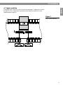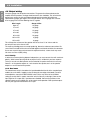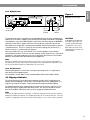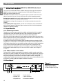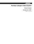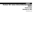
1
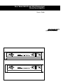
Bose® Model 1800-VI and 1600-VI Professional
Stereo Power Amplifier
Owner’s Guide
1.0 Safety Information
English
Warning
To reduce the risk of fire or electric shock, do not expose the unit to rain or moisture.
CAUTION
CAUTION
RISK OF ELECTRICAL SHOCK
DO NOT OPEN
CAUTION: TO REDUCE THE RISK OF ELECTRIC SHOCK,
DO NOT REMOVE COVER (OR BACK).
NO USER-SERVICEABLE PARTS INSIDE.
REFER SERVICING TO QUALIFIED PERSONNEL.
These CAUTION marks are located on the back of the Model 1800-VI or 1600-VI Professional Stereo Power Amplifier.
The lightning flash with arrowhead symbol, within an equilateral triangle, is intended to alert
the user to the presence of uninsulated dangerous voltage within the system enclosure that
may be of sufficient magnitude to constitute a risk of electric shock.
The exclamation point within an equilateral triangle, as marked on the system, is intended to
alert the user to the presence of important operating and maintenance instructions in this
owner’s guide.
Information about products that generate electrical noise
If applicable, this equipment has been tested and found to comply with the limits for a Class
A digital device, pursuant to Part 15 of the FCC Rules. These limits are designed to provide
reasonable protection against harmful interference in a residential installation. This equipment generates, uses, and can radiate radio frequency energy and, if not installed and used
in accordance with the instructions, may cause harmful interference to radio communications. However, this is no guarantee that interference will not occur in a particular installation. If this equipment does cause harmful interference to radio or television reception,
which can be determined by turning the equipment off and on, you are encouraged to try to
correct the interference by one or more of the following measures:
• Reorient or relocate the receiving antenna.
• Increase the separation between the equipment and receiver.
• Connect the equipment to an outlet on a different circuit than the one to which the
receiver is connected.
• Consult the dealer or an experienced radio/TV technician for help.
Please read this owner’s guide
The Model 1800-VI and 1600-VI Professional Stereo Power Amplifiers are carefully engineered to provide sound quality far beyond other music systems. This guide will help you
set up and operate your system properly.
Record your serial number here:
Model 1800-VI Professional Stereo Power Amplifier: ________________________________
Model 1600-VI Professional Stereo Power Amplifier: ________________________________
Date of purchase _______________________ Retailer’s name _______________________
For ease in obtaining service, we recommend that you keep your purchase receipt, or a
copy of the receipt, in this owner’s guide.
2
1.0 Safety Information
Atención
English
Para reducir el riesgo de incendio o descarga eléctrica, no exponga este aparato a la
lluvia ni a la humedad.
PRECAUCIÓN
PELIGRO DE DESCARGA
ELÉCTRICA NO ABRIR
ATENCIÓN: PARA REDUCIR EL RIESGO DE SUFRIR UNA
DESCARGA ELÉCTRICA, NO RETIRE LA CUBIERTA
(NI LA TAPA TRASERA). EN EL INTERIOR DEL APARATO
NO HAY NINGUNA PIEZA CUYO MANTENIMIENTO
PUEDA REALIZAR EL USUARIO. TODAS LAS OPERACIONES
DE MANTENIMIENTO DEBEN SER REALIZADAS POR
PERSONAL CUALIFICADO.
Estas marcas de ATENCIÓN están situadas en la parte posterior del amplificador de
potencia estéreo profesional Modelo 1800-VI o 1600-VI.
Español
El símbolo de relámpago dentro de un triángulo equilátero indica al usuario que
en el interior de la carcasa del sistema existen tensiones peligrosas no aisladas
de intensidad suficiente como para representar un riesgo de sufrir una descarga
eléctrica.
El signo de admiración dentro de un triángulo equilátero, como el que aparece
marcado en el sistema, indica que en la guía del usuario se ofrecen instrucciones
de manejo y mantenimiento importantes
Avvertenza
Per ridurre il rischio d’incendio o di scossa elettrica, non esporre l’unità alla pioggia o
all’umidità.
Italiano
Français
ATTENZIONE
RISCHIO DI SCOSSA
ELETTRICA NON APRIRE
ATTENZIONE: PER RIDURRE IL RISCHIO DI SCOSSA
ELETTRICA, NON RIMUOVERE IL COPERCHIO (O IL
PANNELLO POSTERIORE). NON VI SONO PARTI INTERNE
RIPARABILI DALL’UTENTE. PER LA MANUTENZIONE,
RIVOLGERSI A PERSONALE AUTORIZZATO.
I simboli di AVVERTIMENTO qui riprodotti rappresentano i simboli che si trovano sul
pannello posteriore degli amplificatori di potenza stereo professionale Modello 1800-VI e
Modello 1600-VI.
Il simbolo del lampo con la freccia, racchiuso in un triangolo equilatero, avverte
l’utente che all’interno dell’apparecchio vi sono parti non isolate sotto tensione di
entità tale da provocare scosse elettriche.
Il punto esclamativo all’interno di un triangolo equilatero, come presente sul
sistema, avverte l’utente dell’esistenza di importanti istruzioni d’uso e di
manutenzione contenute in questo manuale.
3
1.0 Safety Information
English
Waarschuwing
Om het gevaar voor brand of elektrische schokken te verminderen, mag het toestel
niet aan regen of vocht worden blootgesteld.
LET OP
GEVAAR VOOR ELEKTRISCHE
SCHOKKEN NIET OPENEN
OPGELET: OM HET RISICO VAN ELEKTRISCHE
SCHOKKEN TE VERMINDEREN, MAG HET DEKSEL
(OF DE ACHTERKANT) NIET WORDEN VERWIJDERD.
ER ZIJN GEEN ONDERDELEN DIE DOOR DE
GEBRUIKER KUNNEN WORDEN GEREPAREERD.
LAAT ONDERHOUD OVER AAN BEVOEGD
Deze waarschuwingssymbolen bevinden zich op de achterkant van de Model 1800-VI en
1600-VI professionele stereo vermogensversterker.
De bliksemstraal met pijlpunt in een gelijkzijdige driehoek dient om de gebruiker
erop attent te maken dat er niet-geïsoleerde, gevaarlijke spanning in de kast van
het apparaat aanwezig is, die voldoende kan zijn om gevaar voor elektrische
schokken op te leveren.
Nederlands
Het uitroepteken in een gelijkzijdige driehoek, zoals op het apparaat gebruikt,
dient om de gebruiker erop attent te maken dat deze gebruiksaanwijzing
belangrijke instructies voor bediening en onderhoud bevat.
4
Contents
English
Where to find...
1.0 Safety Information ..................................................................................................... 2
2.0 Before You Begin....................................................................................................... 6
2.1 Unpacking the amplifier ...................................................................................... 6
3.0 The Bose® Model 1800-VI and 1600-VI Professional Stereo Power Amplifiers ........ 6
4.0 Installation .................................................................................................................. 7
4.1 Location and general precautions ....................................................................... 7
4.2 Mechanical considerations ................................................................................. 7
4.2.1 Rear support for road applications ........................................................... 7
4.3 Thermal considerations ....................................................................................... 7
4.4 AC power considerations .................................................................................... 7
4.5 Magnetic leakage consideration ......................................................................... 7
4.6 Input wiring .......................................................................................................... 8
4.6.1 Balanced operation .................................................................................. 8
4.6.2 Unbalanced operation .............................................................................. 9
4.7 Input sensitivity ................................................................................................. 11
4.8 Output wiring ..................................................................................................... 12
4.8.1 Polarity .................................................................................................... 12
4.8.2 Dual mono .............................................................................................. 12
4.8.3 Bridged mono ......................................................................................... 13
4.8.4 Parallel mono .......................................................................................... 13
4.9 Clipping eliminator ............................................................................................ 13
5.0 Operation ................................................................................................................ 14
5.1 Using the Bose® Model 1800-VI or 1600-VI Professional
Stereo Power Amplifier ..................................................................................... 14
5.2 Input modules ................................................................................................... 14
5.2.1 Standard input module ........................................................................... 14
5.2.2 ACM-1 amplifier control module ............................................................ 14
5.3 Front panel ........................................................................................................ 14
5.3.1 Power switch .......................................................................................... 15
5.3.2 Standby LED ........................................................................................... 15
5.3.3 AC power fuse ........................................................................................ 15
5.3.4 Level controls ......................................................................................... 15
5.3.5 Status indicators ..................................................................................... 15
5.3.6 Data receive indicator ............................................................................. 15
5.4 Rear panel ......................................................................................................... 16
5.4.1 Stereo/mono switch ............................................................................... 16
5.4.2 Clipping eliminator switch ...................................................................... 16
5.4.3 Input connectors ..................................................................................... 16
5.4.4 EQ OUT connectors ............................................................................... 17
5.4.5 Equalizer LEDs ........................................................................................ 17
5.4.6 EQ Bi-Amp/full range switch .................................................................. 17
5.4.7 Level defeat switch ................................................................................. 17
5.4.8 Sequencer connector ............................................................................. 17
5.4.9 Speaker outputs ..................................................................................... 18
5.4.10 Power cord ............................................................................................. 18
6.0 Troubleshooting ....................................................................................................... 19
7.0 Features ................................................................................................................... 20
8.0 Warranty, Service ..................................................................................................... 21
9.0 Specifications .......................................................................................................... 22
Appendix: Technical Data Sheets (Español, Italiano, Nederlands)
Bose® Corporation ................................................................................. inside back cover
5
English
2.0 Before You Begin
Congratulations on your purchase of a new Bose® Professional Stereo Power Amplifier. It is
backed by state-of-the-art engineering and manufacturing techniques to bring you the
best in quality craftsmanship and reliable performance.
2.1 Unpacking the amplifier
Carefully unpack your amplifier. Keep the original carton and packing materials for possible
future use. Check for any visible signs of damage. If the amplifier appears damaged, do not
try to use it. Notify the Bose Product Support or your authorized Bose Professional Products dealer.
3.0 The Bose Model 1800-VI and 1600-VI
Professional Stereo Power Amplifiers
The Bose Model 1800-VI and 1600-VI Professional Stereo Power Amplifiers are specially
designed for professional sound applications. Their rugged construction and low profile
allow each amplifier to sustain the abuses of the road with reliability and space-saving
economy. Also, their accurate sound and ample power make these amplifiers ideal for
critical studio applications.
The 1800-VI amplifier is rated at 600 watts per channel into 4 ohms and 450 watts per
channel into 8 ohms. In bridged mono operation, it is rated at 1400 watts into 8 ohms.
The 1600-VI amplifier is rated at 325 watts per channel into 4 ohms and 240 watts per
channel into 8 ohms. In bridged mono operation, it is rated at 700 watts into 8 ohms.
The sophisticated protection circuits designed into each amplifier will protect your system
from unexpected faults. They also protect each amplifier from excessive temperature,
continuous current limiting, and shorted outputs.
The balanced inputs of each amplifier use a high quality, high common-mode rejection
differential amplifier for exceptional hum and noise rejection.
In addition, both the 1800-VI and the 1600-VI amplifiers are equipped with an input board
that allows different equalization for each channel (provided the correct equalization card
is installed). Equalization cards (EQ cards) are available for Bose 402®, 502®A, 502B, and
802® loudspeakers.
A sample setup might involve one Model 1800-VI amplifier driving two channels of 802
loudspeakers in stereo mode. A second Model 1800-VI could be added to drive a 502B
module. Alternatively, just one amplifier could be used to drive the 802 loudspeakers on one
channel and the 502B module on the other channel. Many configurations are possible using
the four loudspeakers above. This flexibility can be achieved by installing the EQ cards for
the desired setup.
6
4.0 Installation
4.1 Location and general precautions
English
Locate the unit where it will not be exposed to rain or moisture. If fluid or a foreign object
enters the unit, disconnect the power plug. Do not pull by the cord; grasp the plug firmly.
Contact an authorized dealer or service center.
Place the unit where it will be protected from heat and allow adequate ventilation. Place it
away from direct heat sources, such as heating vents and radiators. Make sure the ventilation holes are not covered and air can circulate freely behind, beside, and above the unit.
4.2 Mechanical considerations
Either amplifier requires two 3.5" rack space units with a 15" depth inside the rack (including
the rear supports). Use four screws with washers to prevent marring the front panel. Neoprene rubber washers are a good choice because they grip the screw head and prevent the
screws from backing out in the event of vibration or if the unit is transported.
4.2.1 Rear support for road applications
If either unit is rack-mounted and the rack is transported, you must mechanically support
the rear of the amplifier. You can place a shelf across the rear of the amplifier or brackets
in such a way as to support the rear of the unit. This practice is recommended for all
electronic instruments.
4.3 Thermal considerations
When either amplifier is used free-standing, no thermal considerations are necessary other
than keeping the ventilation holes open.
If the unit is rack-mounted, allow for adequate ventilation exits in front of and behind the
amplifier. When several amplifiers are mounted together in a rack, you may need to provide
air inlets from the outside of the rack.
The unit is fan cooled. The fan is internally mounted so that it draws air in from the front and
exhausts it out the rear. This allows cool air from outside the amplifier to flow over and cool
the power supply components located in front of the heatsinks.
These amplifiers may be stacked directly on top of each other without spacer panels. If an
amplifier is used with other amplifiers, be sure the heat output from each amplifier does not
interfere with the ventilation of the others.
4.4 AC power considerations
Be sure to plug your amplifier into an outlet capable of supplying the correct voltage
specified for your model. Check to be sure there is enough current to allow full-power
operation of all the amplifiers in your system.
The power plug serves as the Main Disconnect device and should always be easily
accessible after installation.
The current demand of a power amplifier varies depending on the impedance of the load,
the output level of the amplifier, and the crest factor and duty cycle of the program material.
For example, consider typical conditions reproducing rock music, with both channels driven
into 4 ohms to the point where musical peaks are just at the clipping point.
Under these conditions, the Bose® Model 1800-VI amplifier requires an average of 6.7 amps
for 120V versions (3.5 amps for 230V versions).
The Bose Model 1600-VI amplifier requires an average of 4.2 amps for 120V versions (2.2
amps for 230V versions).
4.5 Magnetic leakage considerations
You can mount the Bose Model 1800-VI or 1600-VI amplifier without concern for magnetic
flux leakage. However, it is not a good idea to mount any power amplifier near a microphone input transformer or magnetic storage media.
7
4.0 Installation
English
4.6 Input wiring
You may use 1/4" phone jacks, XLR connectors, and quick connect terminal block
connectors for the input signal with either unbalanced 2-conductor or balanced
3-conductor cables. Use shielded coaxial cable to conduct the signal from the
source (mixer, equalizer, CD player) to the amplifier.
4.6.1 Balanced operation
For the 1/4" phone jack, use a 3-conductor TRS 1/4" phone plug. The tip of the plug
carries the + (hot, non-inverting) side of the signal. The ring carries the – (low, inverting)
side of the signal. The sleeve is ground (see Figure 1).
Figure 1
1/4" phone jack balanced input
connection.
For the XLR, use a male XLR connector. Pin 2 carries the + (hot, non-inverting) side of the
signal. Pin 3 carries the – (low, inverting) side of the signal. Pin 1 is ground (see Figure 2).
Figure 2
XLR balanced input connection.
8
4.0 Installation
English
For the quick connect terminal block, use the female connector provided. Pin 3 carries
the + (hot, non-inverting) side of the signal. Pin 2 carries the – (low, inverting) side of the
signal. Pin 1 is ground (see Figure 3).
Figure 3
Quick connect terminal block
balanced input connection.
If you are using the standard input module for either amplifier, the polarity of the balanced
inputs can be reversed by changing four jumpers located on the input board, just behind the
input connectors. If you are using the ACM-1 module for either amplifier, the polarity cannot
be reversed. Refer to page 12 for a description of the different modules.
4.6.2 Unbalanced operation
For the 1/4" phone jack, use a 2-conductor (tip-sleeve) 1/4" phone plug. The tip of the plug
carries the signal and the sleeve is ground. The ring connection in the jack is automatically
grounded by the sleeve (see Figure 4).
Figure 4
1/4" phone jack unbalanced
input connection.
9
English
4.0 Installation
For the XLR, pin 2 carries the + (hot, non-inverting) side of the signal, and pin 1 is
ground. To reference the input differential amplifier for the correct gain, short pin 3
to pin 1 (see Figure 5).
Figure 5
1/4" XLR unbalanced input
connection.
For the quick connect terminal block, pin 3 carries the + (hot, non-inverting) side of the
signal, and pin 1 is ground. Short pin 2 to pin 1 in order to reference the input differential
amplifier for the correct gain (see Figure 6).
Figure 6
Quick connect terminal block
unbalanced input connection.
Note
The gain remains the same regardless of whether the input is balanced or unbalanced.
10
4.0 Installation
4.7 Input sensitivity
English
The amplifier input sensitivity is set to 0.775V rms for rated output. To reduce the sensitivity
by 6 dB to 1.5V rms, simply remove JP100(CH1) and JP200(CH2), located on the main
amplifier board (see Figure 7).
Figure 7
Input sensitivity modification.
11
4.0 Installation
English
4.8 Output wiring
Use heavy gauge wire for speaker connections. The greater the distance between the
amplifier and the speakers, the larger the diameter the wire should be. This will minimize
power losses across the wire and improve damping of the speaker. Wire thickness
specifications (gauges) get larger as the wire gets thinner. So a 14-gauge wire is thicker
than 18-gauge wire. Use the following chart as a guide.
Wire Length
Gauge of Wire
Up to 15'
18 gauge
15' to 25'
16 gauge
25' to 40'
14 gauge
40' to 60'
12 gauge
60' to 100'
10 gauge
100' to 150'
8 gauge
150' to 250'
6 gauge
This will keep the resistance of the speaker wire to less than 5% of 4 ohms and the
transmission loss to less than 0.5 dB.
The multi-way binding posts can accept spade lug, bare wire, or banana connections. Be
sure all the fine strands of the wire are twisted together and contained within the connector.
If even one strand is loose and can touch the adjacent terminal, a short circuit may result.
You must use Class I (NEC) wiring.
4.8.1 Polarity
In order to have correct phasing between loudspeakers, you must connect them with consistent
polarity. While incorrect phasing will do no physical harm, it will diminish your bass response.
The key is to make sure both speakers are connected to the speaker terminals the same way.
Connect – at the speaker outputs to – on the back of the speaker, and + at the speaker
outputs to + on the back of the speaker.
4.8.2 Dual mono
The stereo/mono switch is located on the input board behind slot #2 of the standard input
module (or, on the AMC-1 module, to the left along the rear edge of the board). For dualmono operation, move the STEREO/MONO switch all the way to the left to the DUAL
setting (or, on the AMC-1 module, move that switch all the way to the right). Connect the
input signal to CH 2 input (CH 1 input becomes disabled). Connect the speakers to the
speaker outputs on the amplifier just as for normal stereo operation. Both speaker outputs
will carry the signal connected to the CH 2 input.
12
4.0 Installation
4.8.3 Bridged mono
English
Figure 8
FOR BRIDGED
OPERATIONS
CONSULT
ON
MANUAL
1800 SERIES VI PROFESSIONAL AMPLIFIER
SER.
D.O.M.
NO.
OFF
ADVERTISEMENT
ENERGIE ELECTRIQUE DANGEREUSE.
BOSE CORPORATION, FRAMINGHAM, MA 01701-9168 MADE IN U.S.A.
LEVEL DEFEAT
OFF
INPUT CH1
SEQUENCE
EQUALIZATION ON
2
1
CH2
EQ. OUT
AVIS
RISQUE DE CHOC ELECTRIQUE
NE PAS OUVRIR
CH 2
CH 1
SPEAKER OUTPUTS
WARNING
3
CH2
CAUTION
RISK OF ELECTRIC SHOCK
DO NOT OPEN
TO REDUCE THE RISK OF FIRE OR ELECTRIC SHOCK
DO NOT EXPOSE THIS EQUIPMENT TO RAIN OR MOISTURE.
CH1
3
2 1
3
200-240 V AC
50-60 Hz
1800 W
CLIPPING
ELIMINATOR
PUSH
INPUT CH2
Bridged mono connection.
700 W 4 Ω
ON
PUSH
1
BRIDGED
1400 W 8 Ω
700 W 4 Ω
LICENSED UNDER U.S. PAT. NO. 4,484,150
INPUT IMPEDANCE 25K OHMS EACH LEG TO GROUND (TOTAL 50K OHMS BALANCED)
SEND
RECEIVE
2
WARNING
RISK OF HAZARDOUS ENERGY! MAKE PROPER
SPEAKER CONNECTIONS. SEE OPERATING
MANUAL BEFORE USING.
CH1
CLASS 1 WIRING SHALL BE USED
GND
Use CH 2
only for input
To “+”
speaker
terminal
To “–”
speaker
terminal
The stereo/mono switch is located on the input board behind slot #2 of the standard input
module (or, on the AMC-1 module, to the left along the rear edge of the board). For bridgedmono operation, move the STEREO/MONO switch all the way to the right to the BRIDGED
setting (or, on the AMC-1 module, move that switch all the way to the left). Connect the
input signal to CH 2 input (CH 1 input becomes disabled). Connect the speakers to the two
+ speaker terminals. The CH 2 + terminal is the hot (non-inverting) side, and the CH 1 +
terminal is the low (–, inverting) side (see Figure 8).
When connected in this way, each channel “sees” half the impedance of the speaker
connected between them. If you use an 8 ohm speaker, each channel will see a 4 ohm load.
Therefore it is not recommended that you use any load lower than 8 ohms in this mode of
operation. Use parallel mono operation for lower impedances.
CAUTION
In bridged mono operation,
the output connections are
actually a balanced output
configuration. This means
both output terminals have
voltage present (neither may
be grounded).
Note
Be sure to set both of the input level controls to the exact same setting for equal power
distribution per channel. Switching the level defeat switch (located on the amplifier) to OFF
will assure that both channels are operating at the same level.
4.8.4 Parallel mono
Parallel mono operation is useful when running sustained high levels in a single load or
when driving a low impedance load.
For instructions, contact Bose® or your authorized Bose Professional Products dealer.
4.9 Clipping eliminator
This circuit prevents the input signal from exceeding the point where it would drive the
amplifier into hard clipping. It has no effect until the signal reaches the clipping point. The
larger the input signal, the more it is reduced to keep the output just below clipping.
The clipping eliminator circuit is operational at the point of manufacture. However, you can
defeat it by using the clipping eliminator defeat switch. This switch is located on the rear
panel of the amplifier. Moving the switch up will re-engage the clipping eliminator.
Note
If you turn the input level down far enough, a sufficiently large input signal can drive the input
differential amplifier into clipping. The clipping eliminator circuit cannot remedy this. It also has
no effect on clipping that occurs prior to the amplifier inputs, such as at the mixer or equalizer.
13
5.0 Operation
5.1 Using the Bose Model 1800-VI or 1600-VI Professional
Stereo Power Amplifier
English
®
Once you have installed and wired the amplifier, follow these tips to get the most from it.
Verify all switches (stereo/mono, clipping eliminator, EQ Bi-Amp/Full Range and level
defeat) are set to the mode you want.
Turn down the amplifier controls when you power up the system for the first time. Then
advance them slowly, one at a time, to verify that each channel is operating correctly.
Set input level controls high enough to allow the preceding device to drive the amplifier
to full output. Usually, this is wide open (fully clockwise).
Mark down the settings, either on paper or self-stick dots attached to the front of the
amplifier.
In bi-amplified (multi-amp) systems, start with the low frequency amps turned down or
off. Check each frequency range from highest to lowest to make sure each loudspeaker
component is operating correctly.
5.2 Input Modules
5.2.1 Standard input module
Through the use of Bose input module (the standard module provided with the amplifier)
and equalization cards, Bose Model 1800-VI or 1600-VI amplifiers can provide active
equalization for Bose 402®, 502®A, 502B, and 802® professional loudspeakers.
Each channel of the input module has its own equalizer card input connector, which allows
different equalization for each channel (provided the correct EQ card is installed). For a view
of the input module, refer to Figure 10 on page 16.
A sample set up might involve one Model 1800-VI amplifier driving two channels of 502A
loudspeakers in stereo mode. A second Model 1800-VI amplifier could be added to drive a
502B module. Alternatively, just one amplifier could be used to drive the 502A loudspeakers
on one channel and the 502B module on the other channel. Many configurations are
possible using the four loudspeakers above. This flexibility can be achieved by installing
the EQ cards for the desired setup. For a view of the ACM-1 module, refer to Figure 11
on page 16.
5.2.2 ACM-1 amplifier control module
The Bose ACM-1 amplifier control module is designed to establish network control of the
Bose 1800-VI or 1600-VI amplifier. This network link makes remote operation of signal level
and power on/off functions possible. The module also provides amplifier monitoring capability. Using the graphical user interface of the ACM-1 module software, settings like
amplifier output, amplifier load, temperature, and clip levels can be checked routinely. Refer
to the ACM-1 installer’s guide for complete installation instructions.
5.3 Front Panel
Figure 9
Front panel of the 1800-VI
amplifier (generally identical to
the 1600-VI amplifier front panel)
2 1
14
3
6
4
1. Power switch
4. Level controls
2. Standby LED
5. Status indicators
3. AC power fuse
6. Data receive indicator
5
5.0 Operation
English
5.3.1 Power switch
The power switch is used as a functional switch and should not be relied upon as a
safety disconnect.
100 volt and 120 volt versions: Press to turn the power ON or on STANDBY. When ON, the
READY indicators will illuminate. In the STANDBY mode, the unit is off but can be activated
through the SEQUENCE connector on the rear panel of the amplifier. Be sure all connections
are made and double checked before switching the power amplifier ON.
Note
Standby (see above) and Sequencing (see below) modes are activated at the amplifier only
when using the standard input module. For the ACM-1 module, these modes are established via the network. For further detail, refer to instructions included with the network.
220-240 volt version: This version has separate POWER and SEQUENCE switches on the
front panel. Press the POWER switch to turn power on (1) or off (0). When the unit is off, no
power reaches the unit and the sequencing function is not active. To use the amplifier in
the normal mode, set the POWER switch on and set the SEQUENCE switch to the off
position ( ). The READY indicators will illuminate. To activate the sequencing function, the
SEQUENCE switch must first be switched to the on position ( ) and then the POWER
switch must be turned on. The unit will then be in a standby mode and can be activated by the
sequence signal. See Section 5.4.8 for additional information regarding the sequence feature.
5.3.2 Standby LED
Illuminates when the power switch is turned OFF to indicate the amplifier is connected to
AC power and the amplifier can be powered up. When the power switch is ON, the standby
LED turns off.
5.3.3 AC power fuse
Protects the amplifier from catastrophic failures that could damage internal circuitry.
Repeated fuse blowing is a sign of internal distress. Refer to an authorized Bose® Service
Center for evaluation.
CAUTION
Always replace with the same
type and value fuse indicated
next to the fuse holder.
5.3.4 Level controls
Used to adjust the input level of each channel. When fully clockwise, the amplifier operates
at maximum gain. Turning the controls counter-clockwise attenuates the input signal.
You can bypass the Level controls internally to lock the amplifier at its full gain capacity.
See the Note about the level defeat switch on page 13.
5.3.5 Status indicators
The ON LED illuminates green when the power is on and the amplifier is ready to operate.
The ON LED illuminates red when the power switch is first turned on (while the power
supply is stabilizing prior to the speaker output relays switching in) or when the amplifier is
in protect mode.
The five SIGNAL LEDs illuminate yellow when a signal is present at the speaker output jacks
to indicate output power relative to full power (0 dB).
The PEAK/PROTECT LED illuminates red when the power switch is first turned on, when the
output begins to clip, or whenever there is a fault condition that causes the output relays to
disengage. These fault conditions include excessive DC offset, excessive heatsink temperature, and short circuits at the speaker outputs.
Note
The relays operate independently for each channel. Therefore, it is possible for one channel
to operate normally while the other is in protect mode.
5.3.6 Data receive indicator
Flashes a yellow light when an installed ACM-1 module is receiving network information.
15
5.0 Operation
English
5.4 Rear panel (see Figures 10 & 11)
5.4.1 Stereo/mono switch
Located on the motherboard of the input module, this switch selects between NORMAL
STEREO, DUAL MONO, or BRIDGED MONO operation.
For NORMAL STEREO operation, use CH 1 and CH 2 inputs. For DUAL MONO or BRIDGED
MONO operation, use CH 2 input only. See the section on bridged operation for more information.
5.4.2 Clipping eliminator switch
You can bypass the clipping eliminator circuit with this switch (located just to the right of
the input panel). Turning the switch OFF deactivates the clipping eliminator and allows the
amplifier to clip when driven beyond its maximum output capability. The clipping eliminator
is operational at the point of manufacture (switch in the up position). For more information
on how the clipping eliminator circuitry works, see Section 4.9.
5.4.3 Input connectors
There are two input connectors per channel which enable three different types of input
connectors to be used. A combination 1/4" TRS (Tip-Ring-Sleeve)/XLR input connector on
the input module allows for either a 1/4" TRS input or a XLR input. A quick connect terminal
block input is also on the input module and is wired in parallel with the TRS/XLR input
connector. This allows for easy connection of stripped wires to a connector which is
provided. Two parallel input connectors allow for simple connection of parallel amplifiers.
Note
When in mono mode, use CH 2 input only.
7
5 6
1800 SERIES VI PROFESSIONAL AMPLIFIER
FOR BRIDGED
OPERATIONS
CONSULT
ON
MANUAL
SER.
D.O.M.
NO.
OFF
WARNING
ADVERTISEMENT
RISK OF HAZARDOUS ENERGY! MAKE PROPER
SPEAKER CONNECTIONS. SEE OPERATING
MANUAL BEFORE USING.
ENERGIE ELECTRIQUE DANGEREUSE.
BOSE CORPORATION, FRAMINGHAM, MA 01701-9168 MADE IN U.S.A.
LEVEL DEFEAT
OFF
INPUT CH1
SEQUENCE
2
EQUALIZATION ON
1
AVIS
RISQUE DE CHOC ELECTRIQUE
NE PAS OUVRIR
CH 2
CH 1
SPEAKER OUTPUTS
WARNING
3
CH2
CH2
CAUTION
RISK OF ELECTRIC SHOCK
DO NOT OPEN
TO REDUCE THE RISK OF FIRE OR ELECTRIC SHOCK
DO NOT EXPOSE THIS EQUIPMENT TO RAIN OR MOISTURE.
CH1
3
2 1
3
200-240 V AC
50-60 Hz
1800 W
CLIPPING
ELIMINATOR
PUSH
INPUT CH2
700 W 4 Ω
ON
PUSH
1
Rear panel of the 1800-VI
amplifier with the standard input
module installed.
BRIDGED
1400 W 8 Ω
700 W 4 Ω
LICENSED UNDER U.S. PAT. NO. 4,484,150
INPUT IMPEDANCE 25K OHMS EACH LEG TO GROUND (TOTAL 50K OHMS BALANCED)
SEND
RECEIVE
2
Figure 10
CH1
CLASS 1 WIRING SHALL BE USED
EQ. OUT
GND
3 4
2
1
1. 1/4" or TRS input
2. Quick connect input
3. EQ OUT connectors
56 7
4. Equalizer LEDs
5. Level defeat switch
6. Sequencer connector
9
8
7. Clipping eliminator switch
8. Speaker outputs
9. Power cord
Figure 11
8
5
FOR BRIDGED
OPERATIONS
CONSULT
ON
MANUAL
1800 SERIES VI PROFESSIONAL AMPLIFIER
SER.
NO.
OFF
ADVERTISEMENT
ENERGIE ELECTRIQUE DANGEREUSE.
USE CHANNEL 1 FOR DUAL MONO
OR BRIDGED MONO OPERATION
STATUS
LED
SERVICE
PIN
INPUT CH 2
3
INPUT CH 1
CH 1
10
AVIS
CAUTION
RISK OF ELECTRIC SHOCK
DO NOT OPEN
RISQUE DE CHOC ELECTRIQUE
NE PAS OUVRIR
WARNING
EQ. OUT
CH 1
SPEAKER OUTPUTS
CLASS 1 WIRING SHALL BE USED
CH1
3 4
2
9
1
1. 1/4" or TRS input
4. Equalizer LEDs
2. Quick connect input
5. Power pack coaxial plug
3. EQ OUT connector
6. Module status LED
7. Service pin
16
CH 2
TO REDUCE THE RISK OF FIRE OR ELECTRIC SHOCK
DO NOT EXPOSE THIS EQUIPMENT TO RAIN OR MOISTURE.
CH 2
CH2
200-240 V AC
50-60 Hz
1800 W
CLIPPING
ELIMINATOR
OFF
02
700 W 4 Ω
ON
INPUT CH 1
EQUALIZATION
ON
Rear panel of the 1800-VI
amplifier with the ACM-1 module
installed.
BRIDGED
1400 W 8 Ω
700 W 4 Ω
LICENSED UNDER U.S. PAT. NO. 4,484,150
A –NETWORK– B
12 V DC
1.6 A
WARNING
RISK OF HAZARDOUS ENERGY! MAKE PROPER
SPEAKER CONNECTIONS. SEE OPERATING
MANUAL BEFORE USING.
BOSE CORPORATION, FRAMINGHAM, MA 01701-9168 MADE IN U.S.A.
LEVEL DEFEAT
ACM-1
INPUT CH 2
D.O.M.
10
8. Network cable connectors
(in parallel)
9. Speaker outputs
10. Power cord
5.0 Operation
English
5.4.4 EQ OUT connectors
A 1/4" TRS output connector provides access to an equalized line level output signal for
each channel. If equalizer cards are installed, this signal has passed through the internal
equalizer, but has not passed through the amplifier itself. (For additional information on
equalization cards, see Input Modules on page 14.)
This is helpful if several devices are going to be driving similar Bose® loudspeakers (802®
loudspeakers, for example) with the same source signal. With equalization cards installed in
the Model 1800-VI or 1600-VI amplifier, the EQ OUT of the amplifier can be connected to
the line level inputs of additional devices driving the same type Bose loudspeakers (i.e. 802).
The type of equalizer cards used must correspond to the type of loudspeakers.
5.4.5 Equalizer LEDs
You can install equalizer cards on the motherboard of the input module by removing the
input module. When you install an equalizer card, the corresponding LED illuminates to
indicate the presence of the card.
Each channel can utilize a different card. For example, the Bose Model 1800-VI Professional
Stereo Power Amplifier can have both a 402® and a 502®B equalizer card installed. When
you install a 502B card in either card position, it automatically selects the high frequency
output of the other card. When a system uses two or more amplifiers, and you are using a
502B module, use the EQ Bi-Amp/Full Range switch to run in the bi-amp mode.
Note
When equalizer cards are installed, the input module automatically senses the cards and
switches to the equalizer circuitry. If no cards are installed, the input module bypasses the
equalizer circuitry.
5.4.6 EQ Bi-Amp/Full Range switch
This switch is located on the motherboard of the input module. The module must be
removed to access this switch. To select the high frequency output from both equalizer
cards, engage this switch (HF ONLY position). The high pass filter begins reducing the
signal below 140 Hz and allows the same equalizer card to be used for full range output
and bi-amp output. This feature is useful when using two or more amplifiers and a 502B
module.
5.4.7 Level defeat switch
This switch is located above the input module and defeats the CHANNEL 1 and CHANNEL 2
LEVEL controls. When the controls are defeated (switch moved to the left) the amplifier gain
is set at the maximum level. The module must be removed to access this switch.
5.4.8 Sequencer connector
This feature is helpful if you are using many amplifiers since it allows amplifiers to sequentially power up. This reduces the initial surge currents from the AC power source to avoid
tripping circuit breakers. The SEND connector of one amplifier is connected to the RECEIVE
connector of the next amplifier. Turn the master power off by switching the equipment rack,
circuit breaker or other main power switch off. The first amplifier in the chain should be in
the normal on position. The subsequent amplifiers should be in the standby mode. When
the master power is turned on, the amplifiers will sequentially power up. For additional
information on switch settings, see Section 5.3.1.
17
English
5.0 Operation
5.4.9 Speaker outputs
Multi-way binding posts connect the loudspeakers to the amplifier outputs. The red
terminals are the signal connection (+) and the black terminals are the signal return
connection (–). The black terminals are internally tied together and to signal ground.
See Section 4.8 for additional output wiring information.
Note
Only connect the Bose® model loudspeaker corresponding to the EQ card installed in
the input module. Use of a different loudspeaker may result in permanent damage to
the loudspeakers.
5.4.10 Power cord
Connect to a properly configured outlet providing the line voltage specified for your model.
Figure 12
1800 SERIES VI PROFESSIONAL AMPLIFIER
FOR BRIDGED
OPERATIONS
CONSULT
ON
MANUAL
WARNING
RISK OF HAZARDOUS ENERGY! MAKE PR
SPEAKER CONNECTIONS. SEE OPERAT
MANUAL BEFORE USING.
SER.
D.O.M.
NO.
OFF
Operational modifications using
the standard input module.
BOSE CORPORATION, FRAMINGHAM, MA 01701-9168 MADE IN U.S.A.
LEVEL DEFEAT
LICENSED UNDER U.S. PAT. NO. 4,484,150
ON
CLIPPING
ELIMINATOR
CAUTION
OFF
RISK OF ELECTRIC SHOCK
DO NOT OPEN
WA
TO REDUCE THE RISK O
DO NOT EXPOSE THIS EQU
NORMAL
DUAL MODE
BRIDGE
STEREO/MONO
SWITCH
EQ BI-AMP
FULL RANGE
SWITCH
EQUALIZER FOR CH 2
EQUALIZER FOR CH 1
INPUT IMPEDANCE 25K OHMS EACH LEG TO GROUND (TOTAL 50K OHMS BALANCED)
SEND
RECEIVE
PUSH
PUSH
INPUT CH2
2
INPUT CH1
SEQUENCE
1
2
EQUALIZATION ON
1
CH1
3
3
2 1
3
CH2
CH2
CH1
EQ. OUT
GND
Figure 13
1800 SERIES VI PROFESSIONAL AMPLIFIER
FOR BRIDGED
OPERATIONS
CONSULT
ON
MANUAL
SER.
D.O.M.
NO.
OFF
WARNING
RISK OF HAZARDOUS ENERGY! MAKE PR
SPEAKER CONNECTIONS. SEE OPERAT
MANUAL BEFORE USING.
BOSE CORPORATION, FRAMINGHAM, MA 01701-9168 MADE IN U.S.A.
LEVEL DEFEAT
LICENSED UNDER U.S. PAT. NO. 4,484,150
ON
CLIPPING
ELIMINATOR
OFF
DUAL
MODE
TO REDUCE THE RISK O
DO NOT EXPOSE THIS EQU
EQ BI-AMP
FULL RANGE
SWITCH
STEREO
SWITCH
EQUALIZER FOR CH 2
EQUALIZER FOR CH 1
A –NETWORK– B
NETWORK MODULE
INPUT CH 2
STANDBY
POWER
USE CHANNEL 1 FOR DUAL MONO
OR BRIDGED MONO OPERATION
STATUS
LED
SERVICE
PIN
INPUT CH 1
EQUALIZATION
ON
INPUT CH 2
02
18
3
CAUTION
RISK OF ELECTRIC SHOC
DO NOT OPEN
WA
BRIDGE
INPUT CH 1
CH 1
10
CH 2
CH2
EQ. OUT
CH1
Operational modifications using
the ACM-1 module.
6.0 Troubleshooting
English
Problems/solutions
If you are having trouble or suspect a problem with the Bose® Model 1800-VI or 1600-VI
Professional Stereo Power Amplifier, try some simple troubleshooting before contacting an
authorized Bose Service Center.
Problem
What to do
No sound, no power
•
•
•
•
•
•
(Usually an indication of a
power supply problem,
either in the power line
itself or the amplifier’s
power supply.)
Power on, low output
or no output
(Usually signal-source,
bad cable or partial
output short circuit
related.)
Amplifier power off. Turn on.
Linecord disconnected.
Poor fit between the plug and AC receptacle. Try another receptacle.
Power off at AC receptacle. Check with tester or lamp.
Blown amplifier fuse. Replace fuse.
Open thermal breaker in the power transformer. Allow amplifier to
cool and the breaker will reset itself.
• Input level controls set too low. Reset.
• Check to see if problem is at the source. Move the input
connections to another amplifier you know is working.
• Be sure that there are no small strands of wire touching similar
strands coming from the other wire in the cable.
• Make sure the speakers are functioning correctly.
• If you are using bridged-mono mode, make sure the stereo/mono
switch is set correctly.
• Use a voltmeter to determine if the power line voltage is dropping
excessively when the amplifier is driven hard.
Playback mixed
with hum
• Check or replace the connecting cables.
• Make sure that each screw terminal connection is tight.
• Signal cables may have been routed too closely to AC cables,
power transformers, motors or other EMI inducing device.
• Connect another source to the power amplifier inputs. If the hum
stops, the problem lies with the original source component.
Distortion
• Check input level controls. If set too low, the preceding piece of
equipment may not have sufficient output to overcome the loss.
• Check speaker connections and verify that all screw connections
are tight and that there are no stray strands of wire to cause
short circuits.
• Verify that the total load impedance presented to the amplifier
is within the limits described in this manual for the mode of
operation selected.
(Usually caused by
excessive loss in the input
controls when the mixer/
equalizer/crossover does
not produce enough
output. Also caused by
over-driving that results in
output clipping, or current
limiting caused by
excessively low load
impedances.)
Unnatural sound
(Some parts of the
frequency band do not
sound balanced with the
rest of the band.)
Care
• Check the EQ cards. Verify that the EQ card corresponds to the
model speaker being used and that the EQ card is installed in the
proper channel. Verify that the speakers are connected to the
same channel that the corresponding EQ card is installed in.
• Wipe the front panel and chassis with a soft, dry cloth.
• For stubborn spots, use a mild dish soap or detergent sparingly
applied to a soft cloth.
• Don’t use alcohol, ammonia, or other strong solvents.
19
7.0 Features
Features of the Bose Model 1800-VI and 1600-VI
Professional Stereo Power Amplifiers
English
®
1800-VI amplifier
1600-VI amplifier
450 watts per channel into 8 ohms
240 watts per channel into 8 ohms
600 watts per channel into 4 ohms
325 watts per channel into 4 ohms
Two input connectors per channel allow 1/4" TRS, XLR, or quick connect terminal
block connection
Two input connectors for each channel are wired in parallel
Accepts balanced or unbalanced lines
Independent CH 1 and CH 2 Level controls with 11 detented positions
Level Control Defeat Switch
Dual Mono mode for operating both channels with a single mono input
Bridged Mono mode for combining the power of both channels into a single higher
powered channel
Sequencer connection for sequentially powering-up multiple amplifiers
Active equalization cards available for the Bose 402®, 502®A, 502B, and 802®, Model 8 and
Model 25/32 loudspeakers.
Bi-Amp/Full Range configurable
Internally configurable for Parallel Mono mode for single channel low impedance operation
Internally configurable for 0.775V or 1.5V rms input sensitivity
Internally configurable input polarity
Class H dual-rail power supply
Independent CH 1/CH 2 speaker relays will instantly disconnect if one of the following fault
conditions is detected: D.C. offset, over temperature, short circuit
Additional protection circuitry includes Clipping Eliminator, AC Line Fuse
Power Connected/Standby indicator
7 LED display per channel, including Power Ready and Clip/Protect indicators
2-speed fan cooled
20
8.0 Warranty, Service
English
Warranty period
Bose® warrants the Bose Model 1800-VI and Model 1600-VI Professional Stereo Power
Amplifier with a five-year, transferable, limited warranty. For more information, please read
the warranty card.
Service
If you experience problems with your Bose Model 1800-VI or 1600-VI Professional Stereo
Power Amplifier, contact your authorized Bose Professional Products dealer. The dealer will
verify any defects and arrange for service.
Please complete the owner’s registration card included with this guide. Return it to Bose
within ten days of purchase.
21
9.0 Specifications
Specifications for Bose Model 1800-VI and 1600-VI
Professional Stereo Power Amplifiers
English
®
Model 1800-VI amplifier
Model 1600-VI amplifier
Power Output
Continuous Average Output Power,
both channels driven:
Power Output
Continuous Average Output Power,
both channels driven:
450 watts per channel into 8 ohms
from 20 Hz to 20 kHz,
with no more than 0.2% THD
240 watts per channel into 8 ohms
from 20 Hz to 20 kHz,
with no more than 0.2% THD
600 watts per channel into 4 ohms
from 20 Hz to 20 kHz,
with no more than 0.2% THD
325 watts per channel into 4 ohms
from 20 Hz to 20 kHz,
with no more than 0.2% THD
Bridged-mono operation:
1400 watts into 8 ohms
from 20 Hz to 20 kHz,
with no more than 0.2% THD
Bridged-mono operation:
700 watts into 8 ohms
from 20 Hz to 20 kHz,
with no more than 0.2% THD
Voltage Output
60V line voltage per channel
into 8 ohms
Voltage Output
43.8V line voltage per channel
into 8 ohms
49V line voltage per channel
into 4 ohms
36.0V line voltage per channel
into 4 ohms
Dynamic Headroom
1.0 dB nominal
Dynamic Headroom
2.0 dB nominal
Gain
High 36.0 dB (± 0.5 dB)
Low 30.3 dB (± 0.5 dB)
Gain
High 33.3 dB (± 0.5 dB)
Low 27.6 dB (± 0.5 dB)
Signal-To-Noise Ratio
>100 dB, A-weighted, referenced to
rated power into 4 ohms (High gain)
Signal-To-Noise Ratio
>100 dB, A-weighted, referenced to
rated power into 4 ohms (High gain)
>78 dBW, A-weighted, referenced to
1W into 4 ohms (High gain)
>79 dBW, A-weighted, referenced to
1W into 4 ohms (High gain)
Power Consumption
55W at idle
Power Consumption
45W at idle
800W with musical program
500W with musical program
1500W at full power into 8 ohms
(continuous)
1000W at full power into 8 ohms
(continuous)
2400W at full power into 4 ohms
(continuous)
1550W at full power into 4 ohms
(continuous)
Fusing
15 amp slo-blo (120V/60 Hz)
8 amp slo-blo (230V/50 Hz)
Fusing
10 amp slo-blo (120V/60 Hz)
7 amp slo-blo (230V/50 Hz)
Weight
Net
Shipping
Weight
Net
Shipping
33 lb (15.0 kg)
39 lb (17.7 kg)
30 lb (13.6 kg)
36 lb (16.3 kg)
Features and specifications are subject to change without notice.
22
9.0 Specifications
Model 1600-VI amplifier sensitivity
High (at 1 kHz)
0.775V rms for rated power into 4 ohms
32mV rms for 1W into 4 ohms
43mV rms for 1W into 4 ohms
Low (at 1 kHz)
1.5V rms for rated power into 4 ohms
Low (at 1 kHz)
1.5V rms for rated power into 4 ohms
61mV rms for 1W into 4 ohms
83mV rms for 1W into 4 ohms
English
Model 1800-VI amplifier sensitivity
High (at 1 kHz)
0.775V rms for rated power into 4 ohms
Specifications common to both amplifiers
Power Bandwidth
5 Hz to 40 kHz (+0, -3 dB)
Frequency Response
20 Hz to 20 kHz (±0.75 dB)
Input Impedance
25 kilohms unbalanced, each leg to ground, 50 kilohms balanced
Channel Separation
> 65 dB @ 1 kHz
> 55 dB @ 10 kHz
Input Overload
+18 dBu
IM Distortion
< 0.1%
THD
@ 0.775V Sensitivity
@ 1.5V Sensitivity
< 0.2%
< 0.1%
Slew Rate
10V/µS (Bandwidth limited)
40V/µS (RFI filtering removed)
CMRR
> 80 dB @ 1 kHz (without Bose® input module)
> 60 dB from 20 Hz-20 kHz (without Bose input module)
Power Requirements
120VAC/50-60 Hz
220-240VAC/50-60 Hz
100VAC/50-60 Hz
Note
Make sure your outlet is capable of supplying the correct voltage specified
for your model.
Display
7 LED indicators per channel
1 green READY, 5 yellow SIGNAL, 1 red CLIP/PROTECT
Size (H x W x D)
3.5" (2U) x 19" x 13.25"
89mm x 483mm x 337mm
23
English
Appendix
Amplificador de potencia estéreo profesional modelo 1600-VI
Descripción general
El amplificador de potencia estéreo profesional Bose® modelo 1600-VI es un sistema de alto rendimiento diseñado para su
utilización junto con todos los sistemas de altavoces profesionales Bose. Se trata de un equipo de gran potencia con un
formato robusto y ligero (13,6 Kg) con una altura de sólo dos unidades de espacio en bastidor (89 mm). Puede utilizarse tanto
en instalaciones portátiles como permanentes.
El 1600-VI es un amplificador de dos canales de gran potencia que proporciona 240 vatios por canal sobre 8 Ω, 325 vatios
por canal sobre 4 Ω, o 700 vatios puenteado sobre una carga de 8 Ω. Ha sido diseñado para aceptar tarjetas acoplables para
ecualización activa para todos los altavoces profesionales de Bose, lo que evita la necesidad de un controlador
independiente.
Español
El amplificador modelo 1600-VI incluye el módulo de ecualización estándar, diseñado para contener hasta 2 tarjetas de
ecualización estándar. Se ha diseñado también un módulo de control opcional del amplificador ACM-1, que también puede
contener hasta 2 tarjetas de ecualización estándar, y que permite gobernar el amplificador a través de una red. Este enlace
de red permite controlar a distancia los niveles de señal y el módulo, así como supervisar el funcionamiento del amplificador.
La interfaz gráfica de usuario del software asociado al módulo ACM-1 permite realizar comprobaciones periódicas de
diversos parámetros, como la salida del amplificador, la carga a la salida, o la temperatura.
El amplificador modelo 1600-VI admite entradas balanceadas o no balanceadas procedentes de conexiones TRS, XLR o de
regletas de terminales. El panel trasero permite conectar a otro dispositivo una entrada paralelo que no se utilice, o las
salidas de nivel de línea con ecualización activa.
Configuración del sistema
Las instrucciones detalladas de instalación y manejo del amplificador 1600-VI se ofrecen en la Guía del usuario del
amplificador de potencia profesional Modelo 1800-VI y 1600-VI.
Información técnica
Potencia de salida
Potencia media de salida constante con ambos canales excitados:
240 vatios por canal sobre una carga de 8 Ω entre 20 Hz y 20 kHz, con una distorsión armónica total (DAT) inferior al 0,2%
325 vatios por canal sobre una carga de 4 Ω entre 20 Hz y 20 kHz, con una distorsión armónica total (DAT) inferior al 0,2%
Funcionamiento en mono puenteado:
700 vatios sobre una carga de 8 Ω entre 20 Hz y 20 kHz, con una distorsión armónica total (THD) inferior al 0,2%
Tensión de salida:
Tensión de línea de 43,8 voltios por canal sobre una carga de 8 Ω
Tensión de línea de 36,0 voltios por canal sobre una carga de 4 Ω
Margen dinámico:
2,0 dB nominales
Ancho de banda de potencia:
5 Hz a 40 kHz (+0 dB, -3 dB)
Respuesta en frecuencia:
20 Hz a 20 kHz (±0,75 dB)
Separación de canales:
(sin el módulo de entrada Bose)
> 70 dB a 1 kHz
> 60 dB a 10 kHz
24
(con el módulo de entrada Bose, sin tarjetas ecualizadoras)
> 65 dB a 1 kHz
> 55 dB a 10 kHz
Appendix
English
Impedancia de entrada
25 kΩ de impedancia asimétrica entre cada ramal y tierra
50 kΩ simétricos
Sensibilidad:
Alta:
0,775 V rms para la potencia nominal sobre una carga de 4 Ω a 1 kHz
43 mV rms para 1 W sobre una carga de 4 Ω a 1 kHz
Baja:
1,5V rms para la potencia nominal sobre una carga de 4 Ω a 1 kHz
83 mV rms para 1W sobre una carga de 4 Ω a 1 kHz
Ganancia:
Alta: 33,3 dB (±0,5 dB)
Baja: 27,5 dB (±0,5 dB)
Sobrecarga a la entrada:
+18 dBu
Distorsión de intermodulación:
< 0,1%
Español
Distorsión armónica total (D.A.T.):
Para la sensibilidad de 0,775V: <0,2%
Para la sensibilidad de 1,5V: <0,1%
Relación señal/ruido:
>100 dB A-Ponderado, referido a la potencia nominal sobre una carga de 4 Ω (alta ganancia)
>79 dBW A-Ponderado, referido a 1 W sobre una carga de 4 Ω (alta ganancia)
Pendiente máxima:
10 V/µS (limitado por ancho de banda)
Rechazo al modo común (CMRR):
>80 dB a 1 kHz (sin el módulo de entrada Bose)
Consumo de potencia:
45 W en reposo
500 W con un programa musical
1000 W a máxima potencia sobre una carga de 8 Ω (continua)
1550 W a máxima potencia sobre una carga de 4 Ω (continua)
Alimentación eléctrica:
120 V CA/50-60 Hz (EE.UU. y Canadá)
230 V CA/50-60 Hz (Europa/Reino Unido)
240 V CA/50-60 Hz (Australia)
100 V CA/50-60 Hz (Japón)
Fusible:
10 amperios, fusión lenta (120 V/60 Hz)
7 amperios, fusión lenta (230 V/50 Hz)
Indicadores:
7 indicadores LED por canal
1 luz verde de sistema preparado (READY), 5 amarillas de señal (SIGNAL) y 1 roja de recorte de protección (CLIP/PROTECT)
Tamaño (Alt. x Anch. x Pr.):
3,5" (2U) x 19" x 13,25"
8,9 cm x 48,3 cm x 33,7 cm
Peso neto:
13,6 Kg
Peso en transporte:
16,3 Kg
25
Appendix
English
Funcionamiento a 70 ó 100 voltios
Cuando se utiliza un amplificador 1600-VI en modo mono puenteado para excitar una línea de 70 ó 100 voltios:
Configuración
de puentes de altavoz
32W
25W
16W
8W
4W
2W
Línea:
70V 100V 70V 100V 70V 100V 70V 100V 70V 100V 70V 100V
Potencia nominal repartida
(vatios por altavoz)
32
16
25 12
16
8
8
Número máximo de
altavoces en la línea
22
44
28 56
44
88
88 175 175 350 350 700
4
4
2
2
1
Información sobre la tarjeta ecualizadora opcional
Para el modelo 1600-VI hay disponibles unas tarjetas que proporcionan ecualización activa para todos los sistemas de
altavoces profesionales de Bose®.
Español
Cada canal tiene su propio slot para la conexión de la tarjeta. Así, por ejemplo, un mismo amplificador puede excitar un canal
de altavoces modelo 402®, y otro canal de altavoces 502®.
Las tarjetas opcionales de ecualización activa proporcionan una compensación en frecuencias adecuada para todos los
sistemas de altavoces profesionales de Bose, sin necesidad de utilizar un controlador independiente. Ofrecen también una
salida de ecualización con nivel de línea para conectar otros amplificadores 1600-VI sin tener que utilizar tarjetas de
ecualización adicionales.
Especificaciones para ingenieros y arquitectos
El amplificador modelo 1600-VI proporciona una potencia constante de 240 vatios con ambos canales excitados sobre una
carga de 8 Ω con una distorsión inferior al 0,2% entre 20 Hz y 20 kHz. Puede entregar 325 vatios de potencia constante con
ambos canales excitados, sobre una carga de 4 Ω con una distorsión inferior al 0,2% entre 20 Hz y 20 kHz. En configuración
mono puenteada, el amplificador entrega 700 vatios de potencia constante sobre una carga de 8 Ω con una distorsión
inferior al 0,2%.
Hay dos conectores de entrada paralelos para cada uno de los dos canales de entrada. Uno de ellos puede conectarse tanto
a un conector TRS de 1/4" como a un conector XLR (sólo puede utilizarse cada vez un conector de entrada). El segundo
conector de entrada es una regleta de terminales de conexión rápida. Las dos regletas de conexiones admiten espadines,
hilo pelado o bananas. Hay dos salidas de señal ecualizadas con nivel de línea de tipo TRS de 1/4", que corresponden a los
dos canales. Esta señal es accesible después de la tarjeta de ecualización interna (si está instalada) y antes de la sección de
amplificación interna.
La separación entre canales es superior a 65 dB a 1 kHz y de 55 dB a 10 kHz, para los dos canales, y el margen dinámico
mayor de 2,0 dB. El ancho de banda de potencia entre 5 Hz y 40 kHz es de +0 dB, -3 dB. La respuesta en frecuencia entre
20 Hz y 20 kHz es de ±0,75 dB. El factor de amortiguamiento es de 170 como mínimo.
La impedancia de entrada es de 25 kΩ no balanceados entre cada ramal y tierra, y 50 kΩ balanceados. La sensibilidad en la
posición alta es de 0,775 voltios rms para la potencia nominal sobre una carga de 4 Ω a 1 kHz, y de 43 mV rms para 1 Vatio
sobre una carga de 4 Ω a 1 kHz. La sensibilidad en la posición baja es de 1,5 voltios rms para la potencia nominal sobre una
carga de 4 Ω a 1 kHz y de 83 mV rms para 1 Vatio sobre una carga de 4 Ω a 1 kHz.
La ganancia es de 33,3 dB, ±0,5 dB, con la configuración de sensibilidad en la posición de entrada alta, y de 27,6 dB,
±0,5 dB, en la baja.
El amplificador consume 1000 vatios de potencia continua sobre una carga de 8 Ω, y 1550 vatios sobre 4 Ω. La unidad tiene
una altura de 3,5" x 19" x 13,25" (8,9 cm x 43,3 cm x 33,7 cm). El peso neto es de 13,6 Kg.
Información sobre homologación
El amplificador modelo 1600-VI cumple la siguiente normativa gubernamental: UL6500 (marchamo ETL), CSA C22.2 Nº 1,
EN60065:1985, así como la normativa de la Unión Europea en materia de emisiones e inmunidad a interferencias
correspondiente al marchamo CE.
Información de garantía
El amplificador modelo 1600-VI está cubierto por una garantía limitada y transferible de 5 años.
26
Appendix
English
Amplificador de potencia estéreo profesional modelo 1800-VI
Descripción general
El amplificador de potencia estéreo profesional Bose® modelo 1800-VI es un sistema de alto rendimiento diseñado
para su utilización junto con todos los sistemas de altavoces profesionales de Bose. Se trata de un equipo de gran
potencia con un formato robusto y ligero (15 Kg) con una altura de sólo dos unidades de espacio en bastidor (89
mm). Puede utilizarse tanto en instalaciones portátiles como permanentes.
El 1800-VI es un amplificador de dos canales de gran potencia que proporciona 450 vatios por canal sobre 8 Ω, 600
vatios por canal sobre 4 Ω, o 1400 vatios puenteado sobre una carga de 8 Ω. Ha sido diseñado para aceptar tarjetas
acoplables de ecualización activa para todos los altavoces profesionales de Bose, lo que evita la necesidad de un
controlador independiente.
El amplificador modelo 1800-VI incluye el módulo de ecualización estándar, diseñado para contener hasta dos
tarjetas de ecualización estándar. Se ha diseñado también un módulo de control opcional del amplificador ACM-1,
que puede contener también dos tarjetas de ecualización estándar, y que permite gobernar el amplificador a través
de una red. Este enlace de red permite controlar a distancia los niveles de señal y el módulo, así como supervisar el
funcionamiento del amplificador. La interfaz gráfica de usuario del software asociado al módulo ACM-1 permite
realizar comprobaciones periódicas de diversos parámetros, como la salida del amplificador, la carga a la salida, o la
temperatura.
Español
El amplificador modelo 1800-VI admite entradas balanceadas o no balanceadas procedentes de conexiones TRS,
XLR o de regletas de terminales. El panel trasero permite conectar a otro dispositivo una entrada paralelo que no se
utilice, o las salidas de nivel de línea con ecualización activa.
Configuración del sistema
Las instrucciones detalladas de instalación y manejo del amplificador 1800-VI se ofrecen en la Guía del usuario del
amplificador de potencia profesional Modelo 1800-VI y 1600-VI.
Información técnica
Potencia de salida
Potencia media de salida constante con ambos canales excitados:
450 vatios por canal sobre una carga de 8 Ω entre 20 Hz y 20 kHz, con una distorsión armónica total (DAT) inferior al
0,2%
600 vatios por canal sobre una carga de 4 Ω entre 20 Hz y 20 kHz, con una distorsión armónica total (DAT) inferior al
0,2%
Funcionamiento en mono puenteado:
1400 vatios sobre una carga de 8 Ω entre 20 Hz y 20 kHz, con una distorsión armónica total (THD) inferior al 0,2%
Tensión de salida:
Tensión de línea de 61,6 voltios por canal sobre una carga de 8 Ω
Tensión de línea de 49 voltios por canal sobre una carga de 4 Ω
Margen dinámico:
1,0 dB nominales
Ancho de banda de potencia:
5 Hz a 40 kHz (+0 dB, -3 dB)
Respuesta en frecuencia:
20 Hz a 20 kHz (±0,75 dB)
Separación de canales:
(sin el módulo de entrada Bose)
(con el módulo de entrada Bose, sin tarjetas ecualizadoras)
> 70 dB a 1 kHz
> 65 dB a 1 kHz
> 60 dB a 10 kHz
> 55 dB a 10 kHz
27
English
Appendix
Impedancia de entrada
25 kΩ de impedancia asimétrica entre cada ramal y tierra
50 kΩ simétricos
Sensibilidad:
Alta:
0,775 V rms para la potencia nominal sobre una carga de 4 Ω a 1 kHz
32 mV rms para 1 W sobre una carga de 4 Ω a 1 kHz
Baja:
1,5V rms para la potencia nominal sobre una carga de 4 Ω a 1 kHz
Español
61 mV rms para 1W sobre una carga de 4 Ω a 1 kHz
Ganancia:
Alta: 36,0 dB (±0,5 dB)
Baja: 30,3 dB (±0,5 dB)
Sobrecarga a la entrada:
+18 dBu
Distorsión de intermodulación:
< 0,1%
Distorsión armónica total (D.A.T.):
Para la sensibilidad de 0,775V: <0,2%
Para la sensibilidad de 1,5V: <0,1%
Relación señal/ruido:
>100 dB A-Ponderado, referido a la potencia nominal sobre una carga de 4 Ω (alta ganancia)
>79 dBW A-Ponderado, referido a 1 W sobre una carga de 4 Ω (alta ganancia)
Pendiente máxima:
10 V/µS (limitado por ancho de banda)
Rechazo al modo común (CMRR):
>80 dB a 1 kHz (sin el módulo de entrada Bose)
Consumo de potencia:
55 W en reposo
800 W con un programa musical
1500 W a máxima potencia sobre una carga de 8 Ω (continua)
2400 W a máxima potencia sobre una carga de 4 Ω (continua)
Alimentación eléctrica:
120 V CA/50-60 Hz (EE.UU. y Canadá)
230 V CA/50-60 Hz (Europa/Reino Unido)
240 V CA/50-60 Hz (Australia)
100 V CA/50-60 Hz (Japón)
Fusible:
15 amperios, fusión lenta (120 V/60 Hz)
7 amperios, fusión lenta (230 V/50 Hz)
Indicadores:
7 indicadores LED por canal
1 luz verde de sistema preparado (READY), 5 amarillas de señal (SIGNAL) y
1 roja de recorte de protección (CLIP/PROTECT)
Tamaño (Alt. x Anch. x Pr.):
3,5" (2U) x 19" x 13,25"
8,9 cm x 48,3 cm x 33,7 cm
Peso neto:
15 Kg
28
Peso en transporte:
17,7 Kg
Appendix
Funcionamiento a 70 ó 100 voltios
English
Cuando se utiliza un amplificador 1800-VI en modo mono puenteado para excitar una línea de 70 ó 100 voltios:
Configuración
de puentes de altavoz
32W
25W
16W
8W
4W
2W
Línea:
70V 100V 70V 100V
70V 100V 70V 100V
70V 100V 70V
100V
Potencia nominal repartida
(vatios por altavoz)
25
12
20
12,5 6,25 6,3
3,1
0,8
Número máximo de
altavoces en la línea
15
30
20 40
10
30
60
3
1,5
1,6
60 120 120 240 235 480
Información sobre la tarjeta ecualizadora opcional
Para el modelo 1800-VI hay disponibles unas tarjetas que proporcionan ecualización activa para todos los sistemas de
altavoces profesionales de Bose®.
Cada canal tiene su propio slot para la conexión de la tarjeta. Así, por ejemplo, un mismo amplificador puede excitar un canal
de altavoces modelo 402®, y otro canal de altavoces 502®.
Especificaciones para ingenieros y arquitectos
El amplificador modelo 1800-VI proporciona una potencia constante de 450 vatios con ambos canales excitados sobre una
carga de 8 Ω con una distorsión inferior al 0,2% entre 20 Hz y 20 kHz. Puede entregar 600 vatios de potencia constante con
ambos canales excitados, sobre una carga de 4 Ω con una distorsión inferior al 0,2% entre 20 Hz y 20 kHz. En configuración
mono puenteada, el amplificador entrega 1400 vatios de potencia constante sobre una carga de 8 Ω con una distorsión
inferior al 0,2%.
Hay dos conectores de entrada paralelos para cada uno de los dos canales de entrada. Uno de ellos puede conectarse tanto
a un conector TRS de 1/4" como a un conector XLR (sólo puede utilizarse cada vez un conector de entrada). El segundo
conector de entrada es una regleta de terminales de conexión rápida. Las dos regletas de conexiones admiten espadines,
hilo pelado o bananas. Hay dos salidas de señal ecualizadas con nivel de línea de tipo TRS de 1/4", que corresponden a los
dos canales. Esta señal es accesible después de la tarjeta de ecualización interna (si está instalada) y antes de la sección de
amplificación interna.
La separación entre canales es superior a 65 dB a 1 kHz y de 55 dB a 10 kHz, para los dos canales, y el margen dinámico
mayor de 1,0 dB. El ancho de banda de potencia entre 5 Hz y 40 kHz es de +0 dB, -3 dB. La respuesta en frecuencia entre
20 Hz y 20 kHz es de ±0,75 dB. El factor de amortiguamiento es de 170 como mínimo.
La impedancia de entrada es de 25 kΩ no balanceado entre cada ramal y tierra, y 50 kΩ balanceado. La sensibilidad en la
posición alta es de 0,775 voltios rms para la potencia nominal sobre una carga de 4 Ω a 1 kHz, y de 32 mV rms para 1 vatio
sobre una carga de 4 Ω a 1 kHz. La sensibilidad en la posición baja es de 1,5 voltios rms para la potencia nominal sobre una
carga de 4 Ω a 1 kHz y de 61 mV rms para 1 Vatio sobre una carga de 4 Ω a 1 kHz.
La ganancia es de 38,0 dB, ±0,5 dB, con la configuración de sensibilidad en la posición de entrada alta, y de 30,3 dB,
±0,5 dB, en la baja.
El amplificador consume 1500 vatios de potencia continua sobre una carga de 8 Ω, y 2400 vatios sobre 4 Ω. La unidad tiene
una altura de 3,5" x 19" x 13,25" (8,9 cm x 43,3 cm x 33,7 cm). El peso neto es de 15 Kg.
Información sobre homologación
El amplificador modelo 1800-VI cumple la siguiente normativa gubernamental: UL6500 (marchamo C-ETL), CSA C22.2 Nº 1
(marchamo CSA), EN60065:1985, así como la normativa de la Unión Europea en materia de emisiones e inmunidad a
interferencias correspondiente al marchamo CE.
Información de garantía
El amplificador modelo 1800-VI está cubierto por una garantía limitada y transferible de 5 años.
29
Español
Las tarjetas opcionales de ecualización activa proporcionan una compensación en frecuencias adecuada para todos los
sistemas de altavoces profesionales de Bose, sin necesidad de utilizar un controlador independiente. Ofrecen también una
salida de ecualización con nivel de línea para conectar otros amplificadores 1800-VI sin tener que utilizar tarjetas de
ecualización adicionales.
30
English
Bose Corporation
Italia
Bose s.p.A., Via della Magliana 876
00148 Roma
www.bose.iT
TEL 06-65670802
FAX 06-65680167
Canada
Bose Ltd., 1-35 East Beaver Creek Road
Richmond Hill, Ontario L4B 1B3
1-800-465-2673
Phone hours - ET (eastern time):
Weekdays 9:00 a.m. to 5:00 p.m.
European Office
Bose Products B.V., Nijverheidstraat 8
1135 GE Edam, Nederland
TEL 0299-390111
FAX 0299-390114
Australia
Bose Pty Limited
1 Sorrell Street
Parramatta NSW, 2150
TEL 02 9204-6111
FAX 02 9204-6122
Japan
Bose K.K., Shibuya YT Building
28-3 Maruyama-cho
Shibuya-ku, Tokyo 150
TEL 3-5489-0955
FAX 3-5489-0592
Nederland
Bose B.V., Nijverheidstraat 8
1135 GE Edam
TEL 0299-390139
FAX 0299-390109
Norge
Bose A/S, Solheimsgate 11
N-2001, Lillestrøm
TEL 63-817380
FAX 63-810819
Österreich
Belgique/België
Bose Ges.m.b.H., Vienna Business Park
Wienerbergstrasse 7 (10.OG)
A-1100 Vienna
TEL 01-60404340
FAX 01-604043423
Bose N.V., Limesweg 2, B-3700 Tongeren
TEL 012-390800
FAX 012-390840
Schweiz
Danmark
Bose A/S, Industrivej 7, 2605 Brøndby
TEL 4343-7777
FAX 4343-7818
Deutschland
Bose GmbH, Max-Planck-Straße 36d
D-61381 Friedrichsdorf
TEL 06172-71040
FAX 06172-710419
France
Bose S.A., 6, rue Saint Vincent
78100 Saint Germain en Laye
TEL 01-30616363
FAX 01-30614105
India
English
USA
Bose Corporation, The Mountain
Framingham, MA 01701-9168
1-800-367-4008
Phone hours - ET (eastern time):
Weekdays 8:30 a.m. to 8:00 p.m.
Saturdays 9 a.m. to 3 p.m.
Bose AG, Rünenbergerstrasse 13
4460-Gelterkinden
TEL 061-9815544
FAX 061-9815502
Sverige
Bose A/S, JohanneFredsgatan 4
S-43153 Mölndal
TEL 31-878850
FAX 31-274891
United Kingdom
Bose Limited
1 Ambley Green
Gillingham Business Park
Gillingham, Kent ME8 ONJ
TEL 0870-741-4500 FAX 0870-741-4545
Bose Corporation India Private Limited
W-16, Greater Kailash-II
New Delhi 110 048
TEL (011) 648 4462 FAX (011) 648 4463
From other locations
Ireland
World Wide Web
Bose Corporation
Carrickmacross, Co Monaghan
TEL (042) 9661988
FAX (042) 9661998
www.bose.com
Bose Customer Service, 1 New York Ave.
Framingham, MA 01701-9168 USA
TEL (508) 766-1900 FAX (508) 766-1919
31
©2000 Bose Corporation
The Mountain, Framingham
MA 01701-9168 USA
198352 AM Rev.02 JN10421
PC023298