1
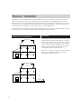
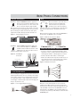
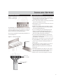
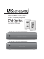
4-Source Multi-Zone Central
Audio Controller/Amplifiers
CAi-Series
Instruction Manual
ROCK
R&B
JAZZ
CHILDRENS
VOLUME
• ON / OFF
• VOLUME
• SOURCE
SOURCE
STORE
POWER
REMOTE SENSOR
Patented
REMOTE SENSOR
CA-KP.2
CA-LCD.2
CA 6.4i 6-Zone, 4-Source Central Controller/Amplifier
CA6.4i 6 Zone — 4 Source Central Controller/ Amplifier
1
2
3
4
5
6
Z ONE
P OWER
CA 4.4i 4-Zone, 4-Source Central Controller/Amplifier
CA4.4i 4 Zone — 4 Source Central Controller/ Amplifier
1
P OWER
2
3
Z ONE
4
IMPORTANT SAFEGUARDS
“WARNING” “ TO REDUCE THE RISK OF FIRE OR ELECTRIC SHOCK,
DO NOT EXPOSE THIS APPLIANCE TO RAIN OR MOISTURE.”
“CAUTION” “ TO REDUCE THE RISK OF ELECTRIC SHOCK, DO NOT
REMOVE COVER. NO USER - SERVICEABLE PARTS INSIDE. REFER
SERVICING TO QUALIFIED SERVICE PERSONNEL.
The lightning flash with arrowhead symbol, within an equilateral triangle, is
intended to alert the user to the presence of uninsulated “dangerous voltage”
within the products enclosure that may be of sufficient magnitude to constitute a
risk of electric shock to persons.
The exclamation point within an equilateral triangle is intended to alert the user
to the presence of important operating and maintenance (servicing) instructions in
the literature accompanying the appliance.
POWER CORD NOTICE FOR INTERNATIONAL OPERATION-Please note that for 230V
50Hz operation please select the power cord for your area. Select the plug for
your area at one end and a IEC320 connector at the other. It is not necessary to
make any other changes. If you have any questions please call Russound Inc.
1800-638-8055 or 603-659-5170
Safety Instructions:
1. Read Instructions - All the safety and operating instructions should be read
before the appliance is operated.
2. Retain Instructions - The safety and operating instructions should be retained
for future reference.
3. Heed Warnings - All warnings on the appliance in the operating instructions
should be adhered to .
4. Follow Instructions - All operating and user instructions should be followed.
5. Water and Moisture - The appliance should not be used near water - for
example, near a bathtub, washbowl, kitchen sink, laundry tub, in a wet basement, or near a swimming pool, and the like.
6. Carts and Stands - The appliance should be used only
with a cart or stand that is recommended by the manufacturer. An appliance and cart combination should
be moved with care. Quick stops, excessive force and
uneven surfaces may cause the appliance and cart combination to overturn.
7. Wall or ceiling Mounting - The appliance should be mounted to a wall or ceiling only as recommended by the manufacturer.
8. Ventilation - The appliance should be situated so that its location or position
does not interfere with its proper ventilation. For example, the appliance
should not be situated on a bed, sofa, rug, or similar surface that may block
the ventilation openings or, placed in a built - in installation, such as a bookcase or cabinet that may impede the flow of air through the ventilation openings.
9. Heat - The appliance should be situated away from heat sources such as radiators, heat registers, stoves, or other appliances ( including amplifiers ) that produce heat.
10. Power Sources - The appliance should be connected to a power supply only of
the type described in the operating instructions or as marked on the appliance.
11. Grounding or Polarization - The precautions that should be taken so that the
grounding or polarization means of an appliance is not defeated .
2
12. Power - Cord Protection - Power supply cords should be routed so that they
are not likely to be walked on or pinched by items placed upon or against
them, paying particular attention to cords at plugs, receptacles, and the point
where they exit from the appliance.
13. Cleaning - The appliance should be cleaned only as recommended by the manufacturer.
14. Non-use Periods - The power cord of the appliance should be unplugged from
the outlet when left unused for a long period of time.
15. Object and Liquid Entry - Care should be taken so that objects do not fall and
liquids are not spilled into the enclosure through the openings.
16. Damage Requiring Service - The appliance should be serviced by qualified
service personnel when:
A. The power - supply cord or the plug has been damaged; or
B. Objects have fallen, liquid has been spilled into the appliance; or
C. The appliance has been exposed to rain; or
D. The appliance does not appear to operate normally; or
E. The appliance has been dropped or the enclosure is damaged.
17. Servicing - The user should not attempt to service the appliance beyond that
described in the operating instructions. All other servicing should be referred
to qualified service personnel.
Precautions:
1. Power – WARNING, BEFORE TURNING ON THE POWER FOR THE FIRST TIME ,
READ THE FOLLOWING SECTION CAREFULLY. All models are designed for use
only with the power supply voltage of the region where they are sold. USA
and Canadian: AC 120c, 60Hz.
2. Voltage Label ( Rear Panel ) – A label located at the rear panel power connection indicates the AC power input for the unit. For use in the USA and Canada
the label will read AC120V, 60 Hz.
3. Do Not Touch The CAi With Wet Hands. Do not handle the CAi or power cord
when your hands are wet or damp. If water or any other liquid enters the CAi
cabinet, take the CAi to qualified service personal for inspection.
4. Location of CAi Place the CAi in a Well - Ventilated Location. Take special care
to provide plenty of ventilation on all sides of the CAi especially when it is
placed in an audio rack. If ventilation is blocked, the CAi may over heat and
malfunction. Do not expose the CAi to direct sun light or heating units as the
CAi internal components temperature may rise and shorten the life of the
components. Avoid damp and dusty places .
5. Care – From time to time you should wipe off the front and side panels and
the cabinet with a soft cloth. Do not use rough material, thinners, alcohol or
other chemical solvents or cloths since this may damage the finish or remove
the panel lettering.
CONTENTS
Product Overview . . . . . . . . . . . . . . . . . . . . . . . . . . . . . . . . .4
Possible System Configurations . . . . . . . . . . . . . . . . . . . . . .4
Unpacking and Warranty . . . . . . . . . . . . . . . . . . . . . . . . . . . .4
Getting Started . . . . . . . . . . . . . . . . . . . . . . . . . . . . . . . . . . .5
Tools Needed . . . . . . . . . . . . . . . . . . . . . . . . . . . . . . . . . . . . . .5
Basic Planning and Layout Considerations . . . . . . . . . . . . .5
Connection Tips . . . . . . . . . . . . . . . . . . . . . . . . . . . . . . . . . . . .5
Rear Panel Connections . . . . . . . . . . . . . . . . . . . . . . . . . . . .6
Source Input Connections . . . . . . . . . . . . . . . . . . . . . . . . . . .6
Speaker Connections . . . . . . . . . . . . . . . . . . . . . . . . . . . . . . .6
Zone Pre-Amp Outputs . . . . . . . . . . . . . . . . . . . . . . . . . . . . .7
12-Volt Trigger Output . . . . . . . . . . . . . . . . . . . . . . . . . . . . . .7
Mute Input . . . . . . . . . . . . . . . . . . . . . . . . . . . . . . . . . . . . . . . .7
Connecting the Infrared Components . . . . . . . . . . . . . . . . .7
Connecting the IR Link . . . . . . . . . . . . . . . . . . . . . . . . . . . . . .7
Keypad Connections at Controller . . . . . . . . . . . . . . . . . . . .8
Wiring at the Controller . . . . . . . . . . . . . . . . . . . . . . . . . . . . .8
Clean Installations . . . . . . . . . . . . . . . . . . . . . . . . . . . . . . . . . .8
Installing Keypads . . . . . . . . . . . . . . . . . . . . . . . . . . . . . . . . .9
Punchdown Terminals . . . . . . . . . . . . . . . . . . . . . . . . . . . . . .9
Installing the Keypads . . . . . . . . . . . . . . . . . . . . . . . . . . . . . .9
Setting the Keypads . . . . . . . . . . . . . . . . . . . . . . . . . . . . . . .10
Source Control Keypads Option . . . . . . . . . . . . . . . . . . . . .10
Infrared Keypad Programmer — IKP-1 . . . . . . . . . . . . . . . .10
SRM-2.1 Speaker Relay Module Option . . . . . . . . . . . . . .11
Speaker Installation . . . . . . . . . . . . . . . . . . . . . . . . . . . . . .11
Operation . . . . . . . . . . . . . . . . . . . . . . . . . . . . . . . . . . . . . . .12
Operating the Main Unit . . . . . . . . . . . . . . . . . . . . . . . . . . .12
Operating the CA-KP.2 Keypad . . . . . . . . . . . . . . . . . . . . . .12
Operating the CA-LCD.2 Keypad . . . . . . . . . . . . . . . . . . . .13
Specifications . . . . . . . . . . . . . . . . . . . . . . . . . . . . . . . . . . .14
Trouble Shooting . . . . . . . . . . . . . . . . . . . . . . . . . . . . . . . . .14
Warranty . . . . . . . . . . . . . . . . . . . . . . . . . . . . . . . . . . . . . . .15
3
PRODUCT OVERVIEW
Congratulations on your recent purchase of a Russound CAi-Series multi-room controller. This four/six-zone, four-source,
multi-room controller is the heart of an affordable whole-house audio distribution system. High-current, stereo, power
amplifiers are built into the Russound CAi allowing simple connections to each speaker in the system. Each zone is operated
by an intuitive, easy-to-use keypad that controls all the functions of the CAi. The keypads also have a built-in infrared receiver that allows remote commands for your source equipment to be routed through the CAi.
The Russound CAi is built with pride. Fidelity, Reliability and Quality are the primary objectives. Russound products are guaranteed to provide years of enjoyment. The CAi conforms to UL and CSA safety specifications.
UNPACKING
POSSIBLE SYSTEM CONFIGURATIONS
ZONE 3
Master Bedroom
ZONE 4
Guest Room
CASSETTE
CD
SOURCE EQUIPMENT
Family Room
ZONE 1
Living Room
ZONE 2
Kitchen
TUNER
CD
CASSETTE
DSS
TUNER
Carefully unpack the unit and keep the original carton and
packing materials for future moving, shipment or long-term
storage. After opening the box, please check for any visible
signs of damage that were not apparent from the outside of
the box. If you do encounter what appears to be concealed
damage, please consult your Russound dealer before proceeding to further unpack or install the unit.
Make sure to save your sales receipt. Your receipt is extremely important to establish the duration of your limited
Warranty, and for insurance purposes.
DSS
(Audio Signal)
CA4.4pi
Controller
Figure 1 - Four-Zones of CA4.4i
ZONE 5
Childs Room
CASSETTE
ZONE 3
Master Bedroom
ZONE 4
Guest Room
CD
CD
SOURCE EQUIPMENT
Family Room
ZONE 1
Living Room
ZONE 2
Kitchen
TUNER
CD
CASSETTE
DSS
TUNER
CD
CA6.4
Controller
Figure 2 - Six-Zones of CA6.4i
4
ZONE 6
Patio
DSS
(Audio Signal)
GETTING STARTED
TOOLS NEEDED
The following information will indicate some tools and
materials necessary for a complete installation:
• 4 twisted pair communication wire (commonly referred to
as CAT-5). This wire will be used to connect the keypads
in each zone to the controller. Stranded, 16 Gauge minimum, CL3 rated wire. This wire is used for direct connection between the CAi and your speakers.
• 110 Punchdown tool (included)
• A medium sized flat-head screwdriver.
• Wire strippers and cutters
• Electric drill and a 1/2" x 6" drill bit
• A steel-wire fish tape
• A keyhole saw
• Electrical junction boxes (6)
• A stud finder
• A screwdriver (cordless recommended)
• Misc. hand tools, nails & screws
• Cable staples
• Modular RJ-45 crimper and connectors
If you have problems or you are not absolutely comfortable
with what you are doing, consult a professional carpenter,
electrician, or system installer.
BASIC PLANNING AND LAYOUT CONSIDERATIONS
• Where will the speakers be located?
• Where will the keypads be located?
• How will the wiring be routed to each location?
• Where is the source equipment located?
• Where is the CAi controller going to be located?
Speaker Wire Length
10-100 feet
100-150 feet
Over 150 feet
Keypad Control
Wire Type
CAT-5
Gauge of Speaker Wire
16 AWG
14 AWG
12 AWG
Max Recommended
Wire Length
250 feet
CONNECTION TIPS
• Disconnect all power cords before connecting to the CAi.
• Verify that all connections and polarity are correct.
• Keep all power cords away from all signal cables to prevent noise or humming.
• Choose reliable signal cables / patch cords.
• Label all wires with room location at both ends of the
wire.
5
REAR PANEL CONNECTIONS
Figure 3 - CA6.4i Rear Panel Connections
Source Input
Connections
CA6.4i NEWMARKET, NH U.S.A.
2
3
Zone Preamp Outputs
ZONE PREAMP
OUTPUTS
1
2
KEYPAD PORTS
SOURCE INPUTS
1
Variable/Fixed
Output Switch
Keypad Zone Input
1
4
2
3
4
5
6
VARIABLE
Voltage Selector Switch
~220-240VAC
VARIABLE
~110VAC
R
R
FIXED
L
FIXED
L
OUTPUT TO 8 OHM SPEAKER
1
LINK
IN
OUT
2
3
4
5
6
MUTE
IN
OUT
IR EMITTERS
Speaker Output Connectors
Emitter Outputs
IR Link
In and Out
Mute Inputs
12V TRIG
WARNING : SHOCK HAZARD – DO NOT OPEN
~110VAC
AVIS : RISQUE DE CHOC ELECTRIQUE –
~220-240VAC
NES PAS OUVRIR.
~50-60Hz
400W
SERIAL #
12 Volt Trigger
Output
VOLTAGE FUSE
110V
F4A
220-240V F2A
AC110/240
Input
Fuse
Holder
Figure 4 - CA4.4i Rear Panel Connections
Source Input
Connections
Keypad Zone Input
CA4.4i NEWMARKET, NH U.S.A.
KEYPAD PORTS
SOURCE INPUTS
1
2
3
Zone Preamp Outputs
1
4
2
3
4
VARIABLE
ZONE PREAMP
OUTPUTS
1
2
R
VARIABLE VARIABLE
R
LINK
OUT
IR Link
In and Out
2
3
FIXED
L
4
IR EMITTERS
Emitter Outputs
IN
Speaker Output Connectors
~110VAC
FIXED
FIXED
L
OUTPUT TO 8 OHM SPEAKER
1
IN
~220-240VAC
VARIABLE
R
FIXED
L
ZONE PREAMP
OUTPUTS
3
4
Voltage Selector Switch
Variable/Fixed
Output Switch
SOURCE INPUT CONNECTIONS
Your source inputs are located at the top left corner of the
back panel. Connect each source output, left and right, using
quality signal cables / patch cables to the CAi source input.
Label each cable the name of your source and the input
number of the CAi you have selected. Repeat until all
sources are connected. List them down below.
List 1 – Source names should be written below
Input 1 ________________ Input 2 ________________
Input 3 ________________ Input 4 ________________
MUTE
OUT
Mute Inputs
12V TRIG
WARNING : SHOCK HAZARD – DO NOT OPEN
~110VAC
AVIS : RISQUE DE CHOC ELECTRIQUE –
~220-240VAC
NES PAS OUVRIR.
~50-60Hz
400W
SERIAL #
12 Volt Trigger
Output
AC110/240
Input
VOLTAGE FUSE
110V
F4A
220-240V F2A
DESIGNED IN USA
MADE IN KOREA
Fuse
Holder
SPEAKER CONNECTIONS
Each speaker connection on the back panel corresponds to
one room/zone. Wire your speakers by first removing the
connector for the chosen zone. Using wire strippers, strip
back 1/4" of the end of the wire. Insert the proper polarity,
left + to left +, left- to left- etc., until all wires are connected in each zone output. Label each wire with the room name
and zone number. Write down the room name to the zone
number below. Note: We recommend 8 Ohm minimum
speakers for each zone. However, speakers as low as 4 Ohm
can be safely used in up to two zones, if necessary.
List 2 – Wire color should be written below
(Color) Left + _______________ Left - _______________
Right + _______________ Right - _______________
List 3 – Room names should be written below
Zone 1 ________________ Zone 2 ________________
Zone 3 ________________ Zone 4 ________________
6
REAR PANEL CONNECTIONS
ZONE PRE-AMP OUTPUTS
MUTE
VARIABLE Switch in VARIABLE Position: In applications
where more power than the 20 watts per channel is desired, connect one or more zones of the
FIXED
CAi to an external amplifier. Using standard
RCA connectors, wire from the pre-amp outputs of the CAi to
the amplifier's inputs. A typical application for more power is
when connecting an outside zone where the audio power
requirements would be much greater than an inside zone.
Figure 5a - Variable Output Connection
VARIABLE
ZONE PREAMP
OUTPUTS
2
1
When used with the optional Doorbell or
MUTE
OUT Telephone interface, the Mute Input
mutes the audio to the speakers, the
doorbell is used or when the telephone
rings. The connection for the Mute Input is made through a
1/8” male mini-plug. The tip is (+) and the sleeve is (-),
12VDC.
IN
When more than one CAi is used, connect the MUTE OUT of
the first CAi to the MUTE IN of the second CAi.
Figure 7 - DIM-1 Doorbell Interface Module
VARIABLE
R
FIXED
FIXED
L
VARIABLE Switch in FIXED Position: When adding subzones, connect an amplifier or A-BUS Hub to
the RCA connection. When the switch is in the
FIXED
FIXED position, the audio level will not be varied by the keypad volume for the zone.
CONNECTING THE INFRARED COMPONENTS
Figure 5b - Fixed Output
Connection
Rear of CAi unit
VARIABLE
L
ZONE PREAMP
OUTPUTS
1
2
A-BUS Hub
1
R
IN
LINK
OUT
FIXED
STATUS
12VDC 100mA
NEWMARKET, NH U.S.A.
VARIABLE
2-ZONE, 1-SOURCE
SURFACE MOUNT AUDIO HUB
KEYPAD OUTPUTS
L
STATUS
R
AUDIO
IN
IR Link In
BYPASS
IR CONFIRM
FIXED
L
POWER
24VDC 4A
2
1
2
3
IR EMITTERS
4
EXPANSION
INPUT
DESIGNED IN USA MADE IN KOREA
R
• In order for your CAi to transmit the IR signal from the
keypads to a source, an emitter must be connected from
the IR outputs marked 1-4. All IR outputs are common
• Connect each 845.1 mini-emitter to the IR output.
• Remove the adhesive back and position the IR receiver on
the product you wish to control. Stick the 845.1 emitter
directly over the source components IR window.
Figure 8 - IR Emitter Connections
A-H2
IR Emitter Out
IR Link Cable
12-VOLT TRIGGER OUTPUT
The 12 volt trigger is engaged when any of the zones are on
and disengaged when the last zone is turned off. The trigger
can be used to engage any 12 volt triggered accessory, such
as a triggered AC outlet or audio amplifier. The connection
for the trigger is made through an 1/8” male mini-plug jack.
The tip is (+) and sleeve is (-).
Figure 6 - 12-Volt Trigger Output Connection
ACT-1
CONNECTING THE (IR) LINK
When two or more CAi Controllers are to be used in an
installation, the LINK connection is used to pass IR signal
between the two units. Use an 1/8” mini-plug, male-to-male
cable (included) connected from the LINK OUT on the first
CAi Controller to the LINK IN on the second CAi. When connected, you may connect your IR emitters to either CAi unit’s
IR EMITTERS jacks.
7
KEYPAD CONNECTIONS AT CONTROLLER
• Each keypad connection on the back panel of the CAi-Series Master
Controller corresponds to the room / zone number chosen for your
speakers. Each zone operates independently, so it is very important to
connect the keypad to the correct zone keypad input.
• On List 4 (opposite) copy down the room name to the zone number
from List 3 on pg 6. NOTE: the keypad and the speakers in each room
must be hooked to the corresponding numbered zone.
List 4 – Room names should be written below.
Zone 1 _________________
Zone 2 _________________
Zone 3 _________________
Zone 4 _________________
CLEAN INSTALLATIONS
BAL
VOL
SEL1
SEL3
+12V
Type
Ground
IR Signal
12VDC+
Source Select
Source Select
Channel Select
Volume
Balance
Figure 10 – Connections with RJ-45 Wall Plate
IR
CAT-5
Brown/White
Brown
Green
Orange/White
Orange
Green/White
Blue/White
Blue
For clean installations, we recommend using RJ-45 jumpers
to run from the CAi controller to an RJ-45 Wall Plate then
running your keypads from the Wall Plate.
CH SEL
CAi System keypads are wired with CAT-5 wire. It is inexpensive and color coded for ease of installation. Due to the
qualities of CAT-5 wire, when using it for keypad control
wire with the CAi-Series, it is recommended to use the following color code for maximum performance. NOTE: 250ft
run of wire maximum per keypad is recommended.
GND
WIRING AT THE CONTROLLER
Figure 9 – Connections with CAT-5 wire
KEYPAD PORTS
1
2
3
4
1 2 3 4 5 6 7 8
8
BROWN
BLUE
ORANGE
GREEN
CAT-5 Cable
ORANGE
RJ-45 using T568A
Wiring Standard
KEYPAD PORTS
1
2
3
4
INSTALLING KEYPADS
PUNCHDOWN TERMINALS
INSTALLING THE KEYPADS
Figure 11 – Punchdown
Terminal on CAi keypad
The CAi Keypads come with 110 punchdown terminals. These
terminals are quick, easy to install and provide a strong connection. Punchdown terminals require the use of a punchdown tool. One has been provided with this kit.
Press wires into punchdown terminal with punchdown tool
as shown in Figure 12.
Figure 12 – Punching Down Wires
VOL
BAL
SEL1
SEL3
CH SEL
+12V
Connector on
CA-KP.2 or CA-LCD.2
BROWN
GREEN
ORANGE
BLUE
GND
IR
Punchdown
Tool
• The best infrared remote performance is achieved with
the keypad away from any direct sunlight. Also consider
convenience when choosing a location.
• Choose a place that is easily seen from the position where
a person is most likely to be located.
• Check whether or not you can route the wire to the location you have chosen.
• Purchase retro-fit plastic junction boxes (min. 18 cubic
inches) or p-rings and cut in the boxes using a key-hole
saw or sheetrock knife/hand saw.
• If you are installing the optional DSC keypad you will
need to use a double-gang electrical box. If you are
installing both the optional DSC and DAN keypad you
will need to install a triple-gang electrical box.
• If you feel uncomfortable cutting into your walls and
running wire through the walls, seek help from a professional installer or an electrician.
• Route the wire to the junction box from the CAi location.
• If using 22 AWG wire, connect each wire to the correct
position 1 thru 8 using the included punchdown tool.
Refer to List 5.
• If using CAT-5 wire, connect each wire to its corresponding color labeled on the punchdown terminal.
• Mount the keypad in the junction box and attach the
Decora plate.
• The CA-KP.2 keypad has source labels for your convenience. Insert the label in the keypad keeping the input
number in sequence with the source selected.
• Repeat the above steps until all keypads are installed.
CAT-5 or 8-conductor
22 AWG wire
9
INSTALLING KEYPADS
SETTING THE KEYPADS
INFRARED KEYPAD PROGRAMMER — IKP-1
Before a keypad is installed into the j-box, turn on the
power so that you can operate the keypad.
CA-LCD.2 Only: The amber and the green backlight brightness can be individually set. Note the brightness controls are
located on the side of the keypad. Adjust to the desired
brightness the backlight that first comes on. Press and hold
the lamp button on the front of the keypad until the backlight switches to the other color. Adjust the brightness for
the selected color.
Both CA-LCD.2 and CA-KP.2: The maximum volume and the
balance should also be set at this time.
Figure 13 - Keypad Adjustments
CA-LCD.2
CA-KP.2
The optional IKP-1 is a programmer used to simplify and
speed up the IR programming for the DAN and DSC IR learning keypads. The IKP-1 programmer is compatible with DAN
and DSC IR Keypads which have a 5-pin programming port
located at the top left of the keypad. Refer to IKP-1
Instruction Manual for complete instructions.
1) Loads IR code in 30 seconds.
2) Simultaneous upload to 4 DAN and or DSC keypads
3) Stores 2 keypad configurations
4) Data cable connection for installed keypads
5) Self powered when used with data cable
6) Non-volatile memory
Programming
Port
Figure 15 – Multiple
Progamming with IKP-1
PRG
ERR
KEYPAD PORT
RST
STO
PRG
CLR
NEWMARKET, NH U.S.A.
ERROR
DAN
DOWNLOAD
FROM KEYPAD
DSC
DATA
TRANSFER
UPLOAD
TO KEYPAD
MORE
PRG
SOURCE CONTROL KEYPADS OPTION
DESIGNED IN USA MADE IN KOREA
PRG
ERR
IR IN
STO
VOLUME
PRG
BALANCE
BALANCE
IR IN
KEYPAD PORT
VOLUME
RST
TO KEYPAD
GREEN BRIGHTNESS
ERR
STO
PRG
CLR
RST
ERR
POWER
12VDC 100mA
STO
PRG
PRG
IR IN
IR IN
RST
KEYPAD PORT
The optional DSC and DAN source control keypads simply
dock into the side of either the CA-KP.2 or CA-LCD.2 keypads via a 16 prong jack. See DSC and/or DAN instruction
manuals for programming instructions.
CLR
IKP-1
INFRARED LEARNING
KEYPAD PROGRAMMER
KEYPAD PORT
LESS
CLR
IKP-1
AMBER BRIGHTNESS
DSC or DAN
KEYPAD
12VDC Power Supply
Figure 14 - Installing the DSC or DAN
Keypad Ports
Error LED
DAN/DSC Program
Toggle Switch
SEEK
MODE
1
2
3
SELECT
4
5
6
SCAN
7
8
9
0
ENTER
Upload
Verification LED
Upload to
Keypad Button
VOLUME
SOURCE
STORE
POWER
Power LED
Download
Verification LED
REMOTE SENSOR
DIRECT SOURCE CONTROL
CA-LCD.2
DSC
DIRECT ACCESS
NUMERIC SOURCE KEYPAD
Download from
Keypad Button
IKP-1
DAN
Keypad Ports
10
12VDC
Connection
SPEAKER INSTALLATION
SRM-2.1 SPEAKER RELAY MODULE OPTION
The optional SRM-2.1 module works with CA-LCD.2 keypad’s
12V trigger output. This unobtrusive wall-mount device
allows you to automatically switch to whole house audio in
a zone containing existing audio equipment. Example: In a
bedroom with a stereo system, the stereo system would be
the default. When you turn on the bedroom's zone at the
keypad the whole house audio system takes control of the
existing stereo speakers.
SPEAKER INSTALLATION
• If you are installing in-wall speakers, follow the instructions provided with your speakers for mounting.
• Connect each speaker wire to the correct polarity (+,-).
Figure 17 - Wire Polarity
If you are using the optional SRM-2.1 speaker relay module,
wire the +, - terminals of the CA-LCD.2 to the SRM-2.1 +, terminals.
-
+
Figure 16 – SRM-2.1 connection to CA-LCD. 2
FINALLY!!!
• Make sure that the voltage selector, located on the rear
panel of the CAi, is on the correct current for your
country, either 110V or 220V
• Power up by plugging in all power cords and turning
the CAi and sources on.
CA-LCD.2
Refer to the SRM-2.1 Instruction Manual for complete
wiring directions.
11
OPERATION
OPERATING THE MAIN UNIT
OPERATING THE CA-KP.2 KEYPAD
• Power switch: When the power switch is engaged, the CAi
power indicator will be lit an amber color. The CAi should be
left on at all times. The unit will consume very little power
unless the zones are on and active. The unit has a stand-by
mode when the zones are inactive.
• Zone Indicators: The zone indicator will light either red
for off or green for on. The zones can only be turned on
from the keypads. All functions are accessed through the
keypad only.
1) Power On / Off: This knob on the CA-KP.2 keypad controls all functions except for the IR management. To turn
the unit on, simply turn the control knob clockwise. You
will feel and hear a click verifying that the unit has been
activated. The lights on the keypad will also illuminate to
verify the zone is now on. Note - The CAi front panel
zone-management lights also informs you which zones
are On or Off.
2) Volume Up / Down: Once the unit is on, the knob can be
used to adjust the volume. To adjust the volume up, turn
the knob clockwise, and to turn the volume down, turn
counter-clockwise.
3) Source Selection: By pressing the knob, the zone will
scroll through the four sources connected to the CAi. The
keypad has four backlit windows that indicate the source
selected.
4) IR Source Control: The IR window repeats all source commands from the source component's remote (or optional
DSC/DAN keypads) through the CAi and 845.1 emitters.
Most IR remotes have a range of 20' at an angle of 60-65
degrees.
Figure 18 - CA-KP.2 Keypad Functions
Source 1
Source 2
ROCK
R&B
JAZZ
CHILDRENS
Source 4
Source 3
• ON / OFF
• VOLUME
• SOURCE
1-Power On / Off
2-Volume Up / Down
3-Source Selection
REMOTE SENSOR
4-IR Source Control
12
OPERATION
OPERATING THE CA-LCD.2 KEYPAD
1) Display: The LCD panel displays the name of the source
selected and the volume level.
2) Source: The source button is pressed to select one of the
four sources to listen to. Press the source button until the
desired source is selected. The source will be displayed on
the LCD display panel.
3) Volume Up / Down: The UP / DOWN arrows for volume
are used to select the volume level and to select a different source name after the store button is pressed. If the
button is pressed and held the volume will ramp up or
down.
4) Lamp: The lamp button when pressed and released will
turn on and off the backlight lamp. The backlight color
can be set to amber or green by pressing and holding the
button. The backlight will change from one color to the
other.
5) Power: Turn on or off any zone by pressing the power
button on the front of the corresponding keypad. When
the keypad comes on, it will automatically select the
source that was previously selected and set the volume to
minimum.
6) Store: The store function is used to select and store one
of the 23 preset source names for each of the four
sources. Select the source name that you want to change
by selecting source. Press and hold the store button for
approximately 3 seconds, and the display begins to flash.
Immediately press the UP/ DOWN volume buttons to
select the different source names. After you have selected
the name, press the store button again or wait for it to
stop flashing.
7) IR Receiver: The IR receiver is used to receive commands
from an IR remote control. Remote controls used for the
source equipment will pass through to the main controller and on to the source equipment. It will receive IR
signals from 38KHz to 56KHz. To control the functions of
the keypad, use the CAi Remote control (see Figure 20).
The CAi remote control will operate the lamp, source
selection, volume up / down and room on / off.
8) IR Confirmation LED: This LED will flash to confirm the
reception of an IR signal from a remote control through
the IR receiver.
Figure 19 - CA-LCD.2 Keypad Functions
Figure 20 - CA-LRC1 Remote Control Functions
SETUP
PWR
CBL
SOURCE
CONTROL
VCR
1
2
3
TV
4
1
2
3
4
5
6
7
8
9
MUTE
0
ENTER
VOL
SLEEP
LAST
CH
INPUT
EXIT
GUIDE
SELECT
INFO
MENU
VOLUME
CA-LCD
VOL
ON
SOURCE
OFF
STORE
POWER
SOURCE SELECT
1
2
3
4
REMOTE SENSOR
13
SPECIFICATIONS
CA6.4i
CA4.4i
• Frequency Response: 20 Hz to 20 KHz ( +/- 1 dB )
• 20 Watts RMS / Channel @ 8Ω
• 12 Channels / 6 Stereo Amplifiers
• Total Harmonic Distortion: .01%
• Signal to Noise Ratio: 89 dB min, “A” weighted
• Power Supply: 110/220V High Current Torroidal
• ETL listed. Conforms to UL Standard UL1492 and CSA
Standard C22-2 No. 1-M94
• Fully Functional Keypad with IR Receiver Centered at
40 kHz and 56K kHz
• Frequency Response: 20 Hz to 20 KHz ( +/- 1 dB )
• 20 Watts RMS / Channel @ 8Ω
• 8 Channels / 4 Stereo Amplifiers
• Total Harmonic Distortion: .01%
• Signal to Noise Ratio: 89 dB min, “A” weighted
• Power Supply: 110/220V High Current Torroidal
• ETL listed. Conforms to UL Standard UL1492 and CSA
Standard C22-2 No. 1-M94
• Fully Functional Keypad with IR Receiver Centered at
40 kHz and 56K kHz
TROUBLESHOOTING
KEYPAD WIRING PROTECTION CIRCUIT
To provide protection for incorrect keypad wiring, this CAiSeries product is equipped with a short circuit protection
device. In the event of a keypad cable short, or incorrect
keypad wiring, this device will automatically interrupt power
to all keypad ports.
Once installed, if the keypads connected to your CAi-Series
product will not turn on, the short circuit protection device
may have been activated. Please take the following steps to
troubleshoot the system.
1) Turn off the power switch on the front of the CAi-Series
controller.
2) Disconnect all keypad connections from the rear of the
controller.
3) Check the wiring configuration for each keypad, checking
both ends (the CAi unit and the CA keypads) of the CAT-5
keypad cable.
4) If incorrect connections were found, correct the wiring
and reconnect the keypads to the controller. After the
controller has been powered off for at least 15 seconds,
turn on the power switch of the CAi-Series controller.
5) If the problem persists, repeat steps above trying each
keypad consecutively.
6) Inadequate ventilation can allow normal heat to build up
and trip the protection circuit.
14
ELIMINATION OF BALANCE LINE
The following diagram shows how resistors may be used at
the Keypad connection on the rear of the CAi master control
unit, to provide 2.5VDC to the balance control line for centering. This circuit will stabilize the balance line input and
keep it centered. They can be used to free up one of the 8
required conductors if one is open, shorted or if an extra
conductor is needed for a secondary IR receiver’s signal in
that zone. Position #7 is GND, #2 is 12VDC, #4 is Balance.
Figure 21 - Balanced
Line Connections
1 2 3 4 5 6 7 8
(#7) Brown/White
GND
(#2)Green
+12VDC
3.9K Ohm
1/4w
820 Ohm
1/4w
(#4) Blue
Balance
TROUBLESHOOTING
COMBINING ADDITIONAL IR RECEIVERS
When combining a CAi Series multi-source controller and a
secondary IR system together, it needs to be done after the
CAi System. The IR information from the keypad is on Pin
#2. This signal is demodulated at the keypad and is re-modulated at the processor then sent to the emitter out-puts.
Combining a modulated IR signal to this lead (#2) will not
work because it is already modulated. The following method
should be used to assure correct integration with such components.
GROUND
SIGNAL
CONNECT TO
846C POWER
SUPPLY
TO SECOND
IR RECEIVER
STATUS
+12VDC
POWER
+12VDC
IR RECEIVER IN
IR COMMON IN
+12VDC
GND
DESIGNED IN USA MADE IN KOREA
857 INFRARED
CONNECTING BLOCK IR CONFIRM
EMITTERS
1
2
3
4
5
6
857
CONNECTING
BLOCK
STATUS
This method combines the modulated IR signal at the connecting block then distributes it to the six emitter ports.
LINK
OUT
SIGNAL
Simply plug the IR linking cable supplied with the CAi product into the IR “Link Out” jack on the CAi and plug the other
end into the Russound 857 IR Connecting Block’s “IR
Common In”. The secondary IR receiver can either be wired
to the terminal block as shown or plugged into the “IR
Reciever In” via an 1/8” mini-plug. The emitters that would
have been connected directly to the CAi system will now be
plugged into the connecting block.
IN
845.1 MICRO EMITTERS
TO IR CONTROLLED
EQUIPMENT
WARRANTY
The Russound CAi-Series Controllers are fully guaranteed for Two (2) years from the date of purchase against all defects in
materials and workmanship. During this period Russound will replace any defective parts and correct any defect in workmanship without charge for either parts or labor. For this warranty to apply, the unit must be installed and used according to its
written instructions. If service is necessary, it must be performed by Russound. The unit must be returned to Russound at the
owners expense and with prior written permission. Accidental damage and shipping damage are not considered defects under
the terms of the warranty. Russound assumes no responsibility for defects resulting from abuse or servicing performed by an
agency or person not specifically authorized in writing by Russound. Damage to or destruction of components due to
improper use voids the warranty. In these cases the repair will be made at the owners expense. To return for repairs, the unit
must be shipped to Russound at the owners expense, along with a note explaining the nature of the service required. Be sure
to pack in a corrugated container with at least 3 inches of resilient material to protect the unit from damage in transit.
15
A / V
D I S T R I B U T I O N
&
C O N T R O L
S Y S T E M S
5 Forbes Rd. Newmarket, NH 03857
☎ 603.659.5170 • Fax 603.659.5388
e-mail: [email protected]
Come visit us at:
28-0106