1
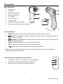
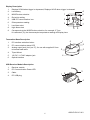
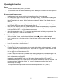
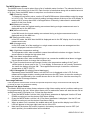
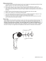
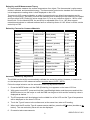
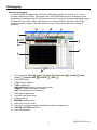
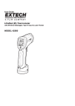
User Guide InfraRed (IR) Thermometer with Wireless Datalogger, Type K input & Laser Pointer MODEL 42560 Introduction Congratulations on your purchase of the Model 42560 IR Thermometer. The Model 42560 IR thermometer measures and displays non-contact (infrared) surface temperature to a maximum of o o 1922 F (1050 C). The built-in laser pointer increases target accuracy while the backlit LCD and handy push-buttons combine for convenient, ergonomic operation. The Type K thermocouple o o input provides contact measurements up to 2498 F (1370 C)*. Adjustable emissivity allows the IR thermometer to accurately measure the temperature of virtually any surface. The Model 42560 is also a datalogging instrument for use with the supplied wireless USB datalogging kit. The kit includes PC software and a USB data receiver (915MHz). The instrument also includes a 20-reading internal memory bank. Other special features include Test Lock, High-Low Alarm display, and MAX-MIN-DIF-AVG memory. This meter is shipped fully tested and calibrated and, with proper use, will provide years of reliable service. o o * The supplied thermocouple is rated to a temperature of 482 F (250 C) maximum. Safety Use extreme caution when the laser pointer is on Do not point the beam toward anyone's eye or allow the beam to strike the eye from a reflective surface Do not use the laser near explosive gases or in other potentially explosive areas 2 42560-EU-EN-V5.1-9/11 Descriptions Meter Description 1 2 1. Laser pointer 2. IR sensor 3. Measurement trigger 4. Battery compartment 5. LCD display 6. Function buttons* 7. Thermocouple 8. Optical interface (meter bottom) 9. Thermocouple input jacks (meter bottom) 3 4 8 9 *Function Buttons MODE: Select from 9 modes of operation explained in detail in this user guide. Arrows: For setting the emissivity, high/low alarm limits, and for scrolling through the 20 internal memory locations Backlight / Laser Pointer: For turning the LCD backlight and the Laser pointer ON/OFF while taking measurements USB: For turning the wireless PC communications ON/OFF SET: For storing a reading to one of the 20 internal memories. ATE: Used during the Automatic Emissivity Adjustment procedure. Note: The function button explanations above are simple overviews. For precise instructions, please read the entire User Guide. Internal Switches (inside battery compartment) o o o 1. Temperature units ( C or F) switch ( C is the left position) 1 2. Test lock ON / OFF switch (OFF is the left position) 2 3. Alarm ON / OFF switch (OFF is the left position) 3 3 42560-EU-EN-V5.1-9/11 Display Description 1. Displays SCAN when trigger is depressed; Displays HOLD when trigger is released 2. Low battery 3. MODE button selection 1 4 5 2 6 3 7 4. Emissivity setting 5. USB PC communication icon 6. IR temperature reading 7. Low Alarm alert 8. High Alarm alert 9. Corresponds to the MODE button selection; for example, if Type K is selected (Tk), the thermocouple temperature reading will display here 8 9 Transmitter Base Description 6 1. PC Interface activation button 2. PC communication status LED 3. Analog output jack (1mV per ºF); for use with supplied 3.5mm to banana lead cable 4. Tripod Mount 5. 12V DC / 117VAC adaptor jack 6. Optical interface 1 2 5 3 4 USB Receiver Module Description 1. Receiver module 2. PC Communication Power LED 3. Cable 4. PC USB plug 1 2 3 4 4 42560-EU-EN-V5.1-9/11 Operating Instructions Power 1. The meter is powered by one (1) 9V battery. 2. The transmitter base can also be powered by the 9V battery in the meter or by the supplied AC adaptor. IR (non-contact) Measurements 1. Hold the meter by its handle and point it toward the surface to be measured. 2. Pull and hold the trigger to turn the meter on and begin testing. The temperature reading, the flashing ‘SCAN’ icon, the emissivity, the unit of measure and other icons as shown in the Display Description will appear. Note: Replace the meter’s 9V battery if the display does not switch on. 3. Release the Trigger and the reading will hold for approximately 7 seconds (HOLD will appear on the LCD) after which the meter will automatically shut off. 4. If the Test Lock switch is set to ON (center DIP switch located inside the battery compartment set to the right position) the meter will remain ON and continue testing until the switch is moved to the left position (OFF) or until the battery loses power. 5. Select the temperature units (ºF/ºC) using the top switch inside the battery compartment. The left switch position is ºC and the right position is ºF. Backlight/Laser Pointer 1. While pulling the Trigger, push the backlight/laser button to turn on the backlight. 2. Press it again to turn on the laser pointer. When the laser is ON the laser icon the LCD. will appear in 3. Press again to turn the backlight off. 4. Press one more time to turn the laser off. Type-K (contact) Measurements 1. Plug the Type-K thermocouple sensor into the jacks at the bottom of the instrument. The jack accepts a standard sub-miniature connector. Note that one plug spade is wider than the other and the plug can only be inserted into the meter in one direction. 2. Pull the trigger to turn the instrument ON. 3. In order to keep the instrument’s power on while testing, the user can a:) hold the trigger or b:) lock the instrument on by setting the center dip switch to the ON position (switches are located inside of the battery compartment). 4. Repeatedly press the MODE button until the bottom display line of the LCD reads ‘T k’. 5. Hold the thermocouple in air or touch the tip of the sensor to the device that is to be tested. The temperature shown to the right of the ‘T k’ symbol is the temperature that the Type-K thermocouple is sensing. o o 6. The supplied thermocouple is rated for a maximum temperature of 482 F (250 C). 5 42560-EU-EN-V5.1-9/11 The MODE button options The MODE button is used to select from a list of available meter functions. The selected function is displayed on the bottom line of the LCD. Each function is listed below along with a detailed account of its use. Press the MODE button to step from one function to the next. EMS (Emissivity Value) To change the emissivity value, use the UP and DOWN arrows (the available emissivity range is 0.10 to 1.00). The current emissivity setting is always shown at the top of the LCD display. A setting of 0.95 covers about 90% of all applications. Emissivity is discussed in a dedicated section of this User Guide. MAX (Maximum function) In the MAX mode, the highest reading encountered during a single measurement scan is displayed next to the MAX icon. MIN (Minimum function) In the MIN mode, the lowest reading encountered during a single measurement scan is displayed next to the MIN icon. DIF (Max minus Min value) In the DIF mode, the MAX less the MIN is displayed next to the DIF display icon for a single measurement scan. AVG (Average value) In the AVG mode, all of the readings in a single measurement scan are averaged and the result is displayed next to the AVG icon. HAL (High Alarm temperature setting) The temperature that, when exceeded, causes the audible/visual alarm to trigger. Use the arrow buttons to change the high alarm limit. LAL (Low Alarm temperature setting) The temperature that, when exceeded high to low, causes the audible/visual alarm to trigger. Use the arrow buttons to change the low alarm limit. T k (Type-K contact thermocouple sensor function) the temperature reading of the Type-K contact probe is shown next to the ‘T k’ icon display. If the sensor is not correctly inserted to the meter the display will show ‘OL‘. The supplied thermocouple is rated for a maximum o o temperature of 482 F (250 C). LOG 1 through 20 (20 reading internal datalogger) Repeatedly press the MODE button unit the LOG icon is displayed on the LCD. Pull the measurement trigger to take a reading and then press the SET button to store the reading to the location represented by the number shown next to the LOG icon. Use the arrow keys to navigate the 20 storage locations. Over-range Indicator If the temperature measurement exceeds the specified temperature range, the thermometer will display OL (overload) in place of a temperature reading. High and Low Alarm Feature The Model 42560 has an alarm feature whereas a High Alarm setting and a Low Alarm setting can be programmed by the user. When either Alarm point is reached the meter will alert the user via an audible beep and LCD display icon. Follow the steps below: 1. Press the MODE button until the HAL (High Alarm) parameter is displayed. Use the UP and DOWN arrow keys to set the desired High Alarm setting. 2. Press the MODE button until the LAL (Low Alarm) parameter is displayed. Use the UP and DOWN arrow keys to set the desired Low Alarm setting. 3. When an alarm limit is reached, the audible alarm will sound and the display icon HIGH or LOW will appear in the lower right hand corner of the LCD. 4. Note that if the bottom DIP switch (located in the battery compartment) is set to OFF (left switch position), the audible alarm will be disabled. 6 42560-EU-EN-V5.1-9/11 IR Measurement Notes 1. The object under test should be larger than the spot (target) size calculated by the field of view diagram (printed on the side of the meter and in this guide). 2. Before measuring, be sure to clean surfaces that are covered with frost, oil, grime, etc. 3. If an object's surface is highly reflective, apply masking tape or flat black paint to the surface before measuring. Allow time for the paint or tape to adjust to the temperature of the surface it is covering. 4. Measurements through transparent surfaces such as glass may not be accurate. 5. Steam, dust, smoke, etc. can obscure measurements. 6. The meter automatically compensates for deviations in ambient temperature. However, it can take up to 30 minutes for the meter to adjust to extremely wide changes. 7. To find a hot spot, aim the meter outside the area of interest then scan across (in an up and down motion) until the hot spot is located. Field of View As the distance from the object increases, the spot size of the area measured becomes larger. The meter’s field of view is 30:1; in other words if the meter is 30 inches from the target (spot), the diameter of the target must be at least 1 inch (see diagram below). Note that measurements should normally be made as close as possible to the device under test. The meter can measure from moderate distances but the measurement may be affected by external sources of light. In addition, the spot size may be so large that it encompasses surface areas not intended to be measured. ( Diameter of objec t) 0.5” 1.0” 1.5” 2.0” 30” 45” 60” 15” ( Distance to object 7 ) 42560-EU-EN-V5.1-9/11 Emissivity and IR Measurement Theory IR Thermometers measure the surface temperature of an object. The thermometer’s optics sense emitted, reflected, and transmitted energy. The thermometer’s electronics translate the information into a temperature reading which is then displayed on the LCD. The amount of IR energy emitted by an object is proportional to an object's temperature and its ability to emit energy. This ability is known as emissivity and is based upon the material of the object and its surface finish. Emissivity values range from 0.1 for a very reflective object to 1.00 for a flat black finish. For the Model 42560, the emissivity is adjustable from 0.1 to 1.00. Most organic materials and painted or oxidized surfaces have an emissivity factor of 0.95. When in doubt, set the emissivity to 0.95. Emissivity Factors for Common Materials Material under test Emissivity Material under test Emissivity Asphalt 0.90 to 0.98 Cloth (black) 0.98 Concrete 0.94 Skin (human) 0.98 Cement 0.96 Leather 0.75 to 0.80 Sand 0.90 Charcoal (powder) 0.96 Soil 0.92 to 0.96 Lacquer 0.80 to 0.95 Water 0.92 to 0.96 Lacquer (matt) 0.97 Ice 0.96 to 0.98 Rubber (black) 0.94 Snow 0.83 Plastic 0.85 to 0.95 Glass 0.90 to 0.95 Timber 0.90 Ceramic 0.90 to 0.94 Paper 0.70 to 0.94 Marble 0.94 Chromium Oxides 0.81 Plaster 0.80 to 0.90 Copper Oxides 0.78 Mortar 0.89 to 0.91 Iron Oxides 0.78 to 0.82 Brick 0.93 to 0.96 Textiles 0.90 Automatic Emissivity Adjustment The 42560 has the ability to automatically calibrate the emissivity setting. However, in order to do so, the temperature of the measured surface must be above 212ºF (100ºC). Follow the steps below to use the automatic emissivity adjustment feature: 1. Press the MODE button until the EMS (Emissivity) icon appears on the lower LCD line. 2. With meter turned OFF, press and hold the Laser/Backlight button and then press and hold the MODE button to turn the meter on until the EMS icon begins to blink and the emissivity value is displayed as dashes “- - - -”. 3. The IR temperature will be displayed on the middle line of the LCD and the Type-K temperature will be displayed on the lower LCD line. 4. Touch the Type-K sensor to the surface and, at the same time, take an IR reading. 5. When both the IR and the Type-K measurements stabilize, press the ATE button (doubles as button). The new emissivity value will now be displayed. 6. Proceed to take measurements. 8 42560-EU-EN-V5.1-9/11 Datalogging Wireless Datalogging The Model 42560 is supplied with a Wireless Datalogging system for use with a PC. The kit contains software (CD-ROM), Transmitter base, and a USB Data Receiver. Readings can be automatically transferred from the IR thermometer to a PC using the wireless datalogging system for distances up to 100 ft. (30m). Instructions for use are provided in the HELP menu of the supplied software program. The Main software screen is reproduced below for preview & reference. , Open , Print , Select Com , On/Off Control buttons: Save , Clear Screen , Clear All , Help . Zoom 2. Emissivity setting 3. MODE button selection 4. TIME: sample rate; UNLOCK/LOCK: Status of test lock dip switch, RANGE: Temperature range of meter; UNIT: Temperature unit of measure 5. Data graph display area 6. High and Low Alarm limits 7. Logged data list 8. MIN MAX display values 9. Date and Time (PC clock) 10. Each time a reading is logged the Data Input block changes color 11. ONLINE, OFFLINE status alert 12. Com port selection 1. 9 , Undo 42560-EU-EN-V5.1-9/11 Analog Output The Model 42560 is supplied with a banana plug pair to 3.5mm mini-plug cable. The mini-plug end of the cable connects to the meter’s Transmitter base. The banana plug test lead end can be connected to an external device such as a MultiMeter, chart recorder, magnetic tape storage device, etc. to collect readings. An analog output of 1mVDC per degree F is provided from the output jack of the transmitter base. Internal Datalogging The 42560 has a 20-reading internal memory. Use the MODE button to scroll to the LOG display (small LOG icon on the bottom left of the LCD). Press and hold the SET button to store the current reading in the memory location represented by the number shown next to the LOG icon. Use the arrow keys to scroll through view data in the 20 locations. FCC Part 15 This equipment has been tested and found to comply with the limits for a Class B digital device, pursuant to part 15 of the FCC Rules. These limits are designed to provide reasonable protection against harmful interference in a residential installation. This equipment generates, uses and can radiate radio frequency energy and, if not installed and used in accordance with the instructions, may cause harmful interference to radio communications. However, there is no guarantee that interference will not occur in a particular installation. If this equipment does cause harmful interference to radio or television reception, which can be determined by turning the equipment off and on, the user is encouraged to try to correct the interference by one or more of the following measures: —Reorient or relocate the receiving antenna. —Increase the separation between the equipment and receiver. —Connect the equipment into an outlet on a circuit different from that to which the receiver is connected. —Consult the dealer or an experienced radio/TV technician for help. Warning: Changes or modifications not expressly approved by the party responsible for compliance could void the user's authority to operate the equipment. 10 42560-EU-EN-V5.1-9/11 Specifications Infrared Thermometer (Non-contact) Specifications Range / Resolution Accuracy o o -50.0 to 1050.0 C (-58.0 to 1922.0 F) o o o Resolution: 0.1 o o ± 5 C (± 9 F) from -50 to -20 C (-58 to -4 F) o o o o ± (1.5% of reading + 2 C [3.6 F]) from -20 to 200 C (-4 to 392 F) o o o o ± (2.0% of rdg + 2 C [3.6 F]) from 200 to 538 C (392 to 1000 F) o o o o ± (3.5% of rdg + 5 C [9 F]) from 538 to 1050 C (1000 to 1922 F) Note: Accuracy is specified for the following ambient temperature range: 18 to 28°C (64 to 82°F) Emissivity Adjustable from 0.10 to 1.00 Field of View D/S = Approx. 30:1 ratio (D = distance; S = spot or target) Laser pointer Class 2(II) laser < 1mW power; Wavelength is 630 to 670nm IR Spectral response 8 to 14 m Type K Thermocouple (Contact) Specifications o o Range / Resolution -50.0 to 1370.0 C (-58.0 to 1999.9 F) Accuracy ± (1.5% of rdg + 3ºC [5ºF]) from -50 to 1000ºC (-58 to 1832ºF) 2000°F to 2498°F* 0.1 o 1° ± (1.5% of rdg + 2ºC [3.6ºF]) from 1000 to 1370ºC (1832 to 2498ºF) Note: Accuracy is specified for the following ambient temperature range: 18 to 28ºC (64 to 82ºF) o o * The supplied thermocouple is rated for 250 C (482 F). General Specifications Display Backlit LCD display with function indicators Display update rate Less than 1 second Internal datalogger 20 reading storage Analog output 1mvDC per °F from jack on Transmitter base (banana to mini-plug cable provided) Wireless Datalogger operating distance 30m (100 ft) approx. Transmitter Frequency 915MHz Operating Temperature 0 C to 50 C (32 F to 122 F) Operating Humidity 80% Relative Humidity max. Power Supply 9V battery or supplied AC adaptor o o o o Automatic Power Off Meter shuts off automatically after 7 seconds Weight 290g / 10.2 oz. Dimensions 100 x 56 x 230mm (3.9 x 2.2 x 9.0”) 11 42560-EU-EN-V5.1-9/11 Battery Replacement When the low battery symbol appears on the LCD, replace the meter’s battery (9V). The battery compartment is located behind the panel that surrounds the meter’s trigger (see diagram). Open the compartment by carefully pulling the panel down away from the trigger area. The panel is hinged at the bottom and does not completely disconnect from the meter. Replace the 9V battery and close the battery compartment cover. Note that the dip switches for TEST LOCK ON/OFF, UNIT OF MEAUSURE C/F selection, and AUDIBLE ALARM ON/OFF, explained earlier in this User Guide, are located in the battery compartment behind the battery. You, as the end user, are legally bound (Battery ordinance) to return all used batteries and accumulators; disposal in the household garbage is prohibited! You can hand over your used batteries / accumulators at collection points in your community or wherever batteries / accumulators are sold! Disposal: Follow the valid legal stipulations in respect of the disposal of the device at the end of its lifecycle Copyright © 2011 Extech Instruments Corporation (a FLIR company) All rights reserved including the right of reproduction in whole or in part in any form. www.extech.com 12 42560-EU-EN-V5.1-9/11