1
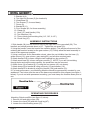
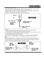
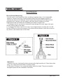
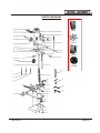
MORTISING MACHINE MODEL 35570 Visit our website at: http://www.harborfreight.com Read this material before using this product. Failure to do so can result in serious injury. SAVE THIS MANUAL. Copyright© 1996 by Harbor Freight Tools®. All rights reserved. No portion of this manual or any artwork contained herein may be reproduced in any shape or form without the express written consent of Harbor Freight Tools. Diagrams within this manual may not be drawn proportionally. Due to continuing improvements, actual product may differ slightly from the product described herein. Tools required for assembly and service may not be included. For technical questions or replacement parts, please call 1-800-444-3353. SPECIFICATIONS Motor Speed Vertical Capacity Throat Table Base Overall Weight 1/2 HP, 2.3 Amps @ 110 V, 60Hz 3580 RPM 5" 5" 13-3/8" x 6" 10" x 7-3/4" 54 lbs. SAVE THIS MANUAL You will need this manual for the safety instructions, assembly instructions, operating procedures, parts list, and diagram. Put them in a safe, dry place for future reference. IMPORTANT SAFETY PRECAUTIONS WARNING: When using electric tools, machines or equipment, basic safety precautions should always be followed to reduce the risk of fire, electric shock, and personal injury. READ ALL INSTRUCTIONS BEFORE USING THIS TOOL. 1 KEEP WORK AREA CLEAN. Cluttered areas invite injuries. 2. CONSIDER WORK AREA CONDITIONS. Don't use machines or power tools in damp, wet, or poorIy lit locations. Don't expose to rain. Keep work area well lit. Don't use tools in the presence of flammable gases or liquids. 3. KEEP CHILDREN AWAY. All children should be kept away from the work area. Don't let them handle machines, tools or extension cords. 4. STORE IDLE EQUIPMENT. When not in use, tools should be locked up in a dry location to inhibit rust. If possible, store in an area out of reach of children. 5. DON'T FORCE THE MACHINE OR TOOL. It will do the job better and more safely at the rate for which it was intended. 6. USE THE RIGHT TOOL. Don't force a small tool or attachment to do the work of a larger industrial tool. Don't use a tool for a purpose for which it was not intended. 7. DRESS PROPERLY. Don't wear loose clothing or jewelry. They can be caught in moving parts. Protective, electrically non-conductive gloves and non-skid footwear are recommended when working, Wear protective hair covering to contain long hair, preventing it from getting caught in machinery. 8. USE EYE AND EAR PROTECTION. Use a full face mask as the mortising machine will produce wood chips. Wear a clean dust mask due to fine or coarse dust. When operating for extended periods of time, use approved ear protection. Face masks, dust masks, anti ear protectors are available from Harbor Freight Tools. 9. DON'T ABUSE THE POWER CORD. Do not yank it to disconnect it from receptacle. Do not move bench-mounted or floor-standing machines with the power cord in the outlet. Keep cord away from heat, oil, and sharp edges. 10. SECURE WORK. Use the included clamps or a vice to hold the work. It's safer than using your hands and it frees both hands to operate the tool. SKU 35570 Page 2 11. KEEP PROPER FOOTING AND BALANCE AT ALL TIMES. Do not reach over or across machines that are running. 12. MAINTAIN TOOLS WITH CARE. Keep tool clean and bits and chisels sharp to provide better and safer performance, Follow instructions for lubricating and changing accessories. Inspect tool cords periodically and if damaged, have them repaired by an authorizer1 service facility. Keep handles dry, clean, and free from oil and grease. 13. DISCONNECT POWER. Unplug when not in use, before servicing, and when changing accessories such as blades, bits, and cutters. 14. REMOVE ADJUSTING KEYS AND WRENCHES. Make it a habit to heck that keys and adjusting wrenches are removed from the tool or machine work surface before plugging it in. 15. AVOID UNINTENTIONAL STARTING. Be sure the switch is in the OFF position when not in use and before plugging in. 16. OUTDOOR EXTENSION CORDS. When the equipment is operated outdoors, use only extension cords intended for outside use. See chart under "Extension Cords" for the proper AWG rating depending upon length of the cord. 17. STAY ALERT. Watch what you are doing, use common sense. Don't operate any tool when you are tired. 18. CHECK DAMAGED PARTS. Before using any tool, any part that appears damaged should be carefully checked to determine that it will operate properly and perform in its intended function. Check for alignment of moving parts, binding of moving parts, breakage of parts, mounting, and other conditions that may affect its operation. Any part that is damaged should be properly repaired or replaced by an authorized service center unless otherwise indicated elsewhere in the instruction manual. Have defective switches replaced by an authorized service center. Don't use the tool if switch does not turn on and off properly. 19. GUARD AGAINST ELECTRIC SHOCK. Prevent body contact with grounded surfaces: pipes, radiators, ranges, and refrigerator enclosures. 20. REPLACEMENT PARTS AND ACCESSORIES. When servicing, use only identical replacement parts. Only use accessories intended for use with this tool. Approved accessories are available from Harbor Freight Tools. 21. DO NOT OPERATE TOOL IF UNDER THE INFLUENCE OF ALCOHOL OR DRUGS. Read warning labels on prescriptions to determine if your judgment or reflexes are impaired while taking drugs. If there is any doubt, do not operate machine. 22. KEEP GUARDS IN PLACE. All guards and fences need to be in proper working order and alignment. Check before every use. 23. NEVER STAND ON TOOL. If tool is tipped over or if blades or cutters are accidentally contacted, serious injury could result. 24. NEVER LEAVE TOOL RUNNING UNATTENDED. Always turn off power. Do not leave tool until it comes to a complete stop. GROUNDING INSTRUCTIONS This machine has a three-prong plug, the third (round) prong being the ground. Plug the machine's cord only into a three-prong receptacle. Do not cut off the round prong. If a three prong receptacle is not available, you may use an adapter, but you must then connect the green ear on the adapter to the outlet. Unscrew the center screw of the outlet cover Page 3 SKU 35570 and put the screw through the green ear. Plug the adapter's two prongs into the outlet, and replace the center screw. Now plug the machine into the adapter. VOLTAGE WARNING Before connecting the tool to a power source (receptacle, outlet, etc.) be sure the voltage supplied is about the same as that specified on the nameplate of the tool. If one says 120V and the other says 110V then there will be no complications. Never try to plug a 110V into a 220V outlet, or the other way around. The plug and outlet have completely different shapes. This is because a power source with a voltage greater than that specified on the tool can result in a SERIOUS INJURY to the user- as well as damage to the tool. If in doubt, DO NOT PLUG IN THE TOOL. Using a power source with voltage (110V) less than the nameplate rating (220V) is harmful to the motor. EXTENSION CORDS Since your tool has a grounded, three-prong plug, you must use a three-prong extension cord with three prong receptacles. Only use rounded jacket extension cords, preferable listed by the Underwriters Laboratories (UL). Make sure the cord is rated for outdoor use if you plan on using the tool outside; if you plan on indoor use, you may also use an outdoor rated cord. Extension cords rated for outdoor use have the letters "WA" on the cord jacket. The extension cord must have a minimum wire size depending on the amperage of the tool and the length of the extension cord. This size is signified by its AWG (American Wire Gauge) rating; the smaller the gauge, the greater the cable's capacity. If you are using two or more cords, the total length of the combined cords must be used to determine the minimum AWG rating. Each of the cords used must meet this rating. The chart below is used to determine the rating required according to the length of the cord(s). The amps of your tool are found either in this manual, or on the nameplate of the tool. CORD(S) LENGTH (FEET) WIRE GAUGE REQUIRED 25 50 75 100 125 150 175 200 18 18 16 16 14 14 12 12 Always inspect extension cords for any damage. If there are any loose, frayed or exposed wires, damaged insulation, or defective connections, replace the cord. Harbor Freight Tools can supply UL listed and outdoor rated cords in multiple AWG ratings if needed. UNPACKING Make sure your tool includes all accessories and pieces required for operation. Check off according to the list below. If any pieces are missing, contact Harbor Freight Tools at the number on the front cover. 1. Mortising Machine 2. Handle (24) SKU 35570 Page 4 3. Bracket A (4) 4. Two Hex Key Screws (5) (for bracket A) 5. Wood Base (6) 6. Two Screws (7, for wood base) 7. Fence (9) 8. Bracket B (11) 9. Four Screws (40, for fence assembly) 10. Clamp (8) 11. Knob (12 ) and Handle (12A) 12. Two Washers (10) 13. Three chisels and mortising bits (1/4", 3/8", & 1/2") 14. Chuck Key (47) ASSEMBLY INSTRUCTIONS 1. Slide handle (24) into the receiver hole on the right side of the gear shaft (20). The handle's end should protrude about a 1/2". Tighten the set screw (19). 2. Using the handle, lower the head of the machine slightly. This will permit removal of the retaining half-washer located on the gear column (15). Gently allow the head assembly to move to the uppermost position. 3. Using a non-toxic & non-flammable solvent, clean the rust inhibitor from the base (3), guide column (16), gear column, gear casing(23), and all other required parts. 4. Attach bracket A (4) to base using the two supplied hex key screws (5). 5. Attach wood base (6) to base using two screws (7). NOTE: If you are not mortising through holes and require extra capacity, the wood base can be removed. 6. Attach fence (9) to bracket B (11) using the four screws (40, not shown). 7. Attach clamp (8) to bracket B using one knob (12) and washer (10). 8. Attach bracket B to bracket A using the Handle (12A) and washer (10). 9. For best performance, your Mortising Machine should be permanently mounted to your workbench. Two holes near the rear of the base are provided for this purpose (see figure 1, below). If you do not wish permanent mounting, you must clamp the machine down prior to use. OPERATING PROCEDURES Attaching Chisels and Bits (see figure 2, below): 1. Remove left and right covers (39). 2. Loosen the chuck (35) with the chuck key(47). 3. Loosen the chisel bushing screw (37). Page 5 SKU 35570 4. Slide the bit into the chisel. 5. Insert the chisel into the bushing (38) and the bit into the chuck. Make sure the chisel's slot is facing either the right or left to provide for proper chip ejection. 6. Make sure there is at least 3/32"-7/32"o f bit protruding from the end of the chisel, then tighten the chuck. Make sure to tighten at all three spots. 7. Tighten the busing screw, and replace the left and right covers. Mortising: 1. Set the fence (9) so that the chisel will mortise your stock in the desired position. 2. Set the hold down clamp (8) so that it securely holds your stock. 3. Set the depth stop (18) at the position required according to the desired depth of the mortise. 4. Turn machine on. It should reach full speed in a few seconds. 5. Slowly lower handle until mortise is complete. 6. Do not mortise holes deeper than 1" at a time. If you wish to mortise to a depth greater than 1", do so in a couple of passes. This will allow the chips to be properly ejected. Slots: Slots and mortises longer or wider than 1/2" can be accomplished simply by moving the wood after the initial cut is accomplished. When doing so, make sure the slot in the chisel is facing the direction you are moving the wood for proper chip ejection. Other than that, the procedure is identical to regular mortising. (See figure 3 below.) SKU 35570 Page 6 MAINTENANCE Bit and Chisel Sharpening: If the bit is dull, it can break the chisel, resulting in operator injury. It is sharpenable, however, if there is any sign of wear along the twist (such as irregular grooves or hollows) the bit must be replaced. Chisels cannot be sharpened if the walls become noticeably thin Typically, you will replace a bit three times as often as a chisel. Replacement bits and chisels are available from Harbor Freight Tools. 1. To sharpen the bit, use a three cornered file and sharpen the inner edge of the spur and the cutting edge of the twist. 2. To sharpen the chisel, first fix it in a vise. Use a tapered stone or rotary, file in a drill. Set the RPM's very low or the temper of the chisel will be affected. Use a file to remove any burrs on the outside face of the chisel. Lubrication: 1. Before every use, lubricate the both columns with a light machine oil. Clean them after every use to prevent accumulation of foreign matter. 2. After every 30 days of use, grease the gears inside the head. They are accessible through the panel on the underside of the head. Page 7 SKU 35570 TROUBLE SHOOTING Problem :LOOQRWVWDUW &DXVH 1RWSOXJJHGLQ )XVHRUFLUFXLWEORZQ 6RFNHWGRHVQRWIXQFWLRQ 6ROXWLRQ 3OXJLQ 5HSODFHIXVHRUUHVHWFLUFXLW THVWVRFNHWZLWKFXUUHQWWHVWHU RUWU\LQJDQRWKHUWRROLQVRFNHW ,IVRFNHWGRHVQ WZRUNKDYHLW UHSODFHGE\DTXDOLILHGHOHFWULFLDQ 'DPDJHGFRUGRUSOXJ +DYHUHSODFHGE\DTXDOLILHG WHFKQLFLDQ +DYHVZLWFKUHSODFHGE\D TXDOLILHGWHFKQLFLDQ &RQWDFW+DUERU)UHLJKWTRROVIRU VHUYLFLQJ 6ZLWFKQRWIXQFWLRQLQJ 0RWRUQRWZRUNLQJ 0DFKLQHVWDUWV EXWELWGRHV QRWPRYH :RUQRUEURNHQJHDUV 5HSODFHJHDUV 2SHUDWLRQ LQWHUUXSWHG )RUFLQJXQLW 2YHUORDGHGFLUFXLW $SSO\OHVVSUHVVXUH 8VHRQLVRODWHGFLUFXLW &KHFNIRUDGHTXDWHDPSUDWLQJ ,QVWDOOSURSHUIXVHVEUHDNHUV IRUFLUFXLW %URNHQ&KLVHOV :RUQELW 6KDUSHQRUUHSODFHELW &KLSVFORJJHGLQ &KLVHO &KLVHOVVORWIDFLQJIRUZDUG RUEDFNZDUG )DFHVORWWRULJKWRUOHIW TRUQRUURXJK PRUWLVHV 'XOOFKLVHO 5HSODFHRUUHVKDUSHQ 6.8 3DJH PARTS LIST Part No. 1 2 3 4 5 6 7 8 9 10 11 12 12A 13 15 16 17 18 19 20 21 22 23 24 25 Page 9 Description Bolt Lock Washer Base Bracket A Hex Key Screw Wood Base Screw Hold Down Clamp Fence Washer Bracket B Knob Handle Spring Gear Column Guide Column Knob Depth Set Guide Set Screw Gear Shaft Gear Gear Access Plate Gear Casing Handle Guide Sleeve 26 27 28 29 29-01 29-02 29-03 29-04 30 31 33 34 35 36 37 38 39 40 42 43 44 45 46 47 48 49 Stop Plate Washer Bolt Motor Capacitor Motor Fan Switch Box Rear Motor Housing Bearing Cover Power Cord Switch Nut Inner Spring Chuck Screw Chisel Bushing Screw Chisel Bushing Guard Cover Screw M5X12 Drill Chuck 1/4’’ Chisel & Bit 3/8’’ Chisel & Bit 1/2’’ Chisel & Bit Drill Shaft Chuck Key Wrench 5mm Wrench 6mm SKU 35570 PARTS DIAGRAM 29-01 29-02 29-03 42 29-04 46 43 44 12A 47 45 40 48 49 SKU 35570 Page 10 LIMITED 90 DAY WARRANTY Harbor Freight Tools Co. makes every effort to assure that its products meet high quality and durability standards, and warrants to the original purchaser that this product is free from defects in materials and workmanship for the period of ninety days from the date of purchase. This warranty does not apply to damage due directly or indirectly, to misuse, abuse, negligence or accidents, repairs or alterations outside our facilities, or to lack of maintenance. We shall in no event be liable for death, injuries to persons or property, or for incidental, contingent, special or consequential damages arising from the use of our product. Some states do not allow the exclusion or limitation of incidental or consequential damages, so the above limitation of exclusion may not apply to you. THIS WARRANTY IS EXPRESSLY IN LIEU OF ALL OTHER WARRANTIES, EXPRESS OR IMPLIED, INCLUDING THE WARRANTIES OF MERCHANTABILITY AND FITNESS. To take advantage of this warranty, the product or part must be returned to us with transportation charges prepaid. Proof of purchase date and an explanation of the complaint must accompany the merchandise. If our inspection verifies the defect, we will either repair or replace the product at our election or we may elect to refund the purchase price if we cannot readily and quickly provide you with a replacement. We will return repaired products at our expense, but if we determine there is no defect, or that the defect resulted from causes not within the scope of our warranty, then you must bear the cost of returning the product. This warranty gives you specific legal rights and you may also have other rights which vary from state to state. 3491 Mission Oaks Blvd. • PO Box 6009 • Camarillo, CA 93011 • (800) 444-3353