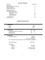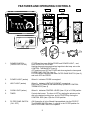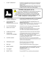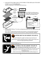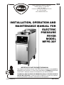
1
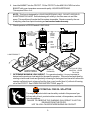
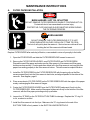
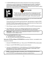
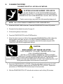
362
WELLS MANUFACTURING COMPANY
2 ERIK CIRCLE, P. O. Box 280
Verdi, NV 89439
Customer Service (775) 345-0444 Ext.502
fax: (775) 345-0569
www.wellsbloomfield.com
INSTALLATION, OPERATION AND
MAINTENANCE MANUAL FOR
ELECTRIC
PRESSURE
FRYER
MODEL
WFPE-30F
IMPORTANT: DO NOT DISCARD THIS MANUAL
This manual is considered to be part of the FRYER and is to be given to the OWNER or
MANAGER of the restaurant, or to the person responsible for TRAINING OPERATORS
of the FRYER. Additional manuals are available from your WELLS DEALER .
THIS MANUAL MUST BE READ AND UNDERSTOOD BY ALL PERSONS USING OR
INSTALLING THIS FRYER. Contact your WELLS DEALER if you have any questions
concerning installation, operation or maintenance of this equipment.
Part No. 301626 Rev (-)
M362 111500 cps
LIMITED WARRANTY STATEMENT
All commercial cooking equipment manufactured by
WELLS MFG. CO. is warranted against defects in
materials and workmanship for a period of one year
from the date of original installation or 18 months
from the date of shipment from our factory, whichever comes first, and is for the benefit of the original purchaser only.
THIS WARRANTY IS THE COMPLETE AND ONLY
WARRANTY, EXPRESSED OR IMPLIED IN LAW
OR IN FACT, INCLUDING BUT NOT LIMITED TO,
WARRANTIES OF MERCHANTABILITY OR FITNESS FOR ANY PARTICULAR PURPOSE, AND/
OR FOR DIRECT, INDIRECT OR CONSEQUENTIAL DAMAGES IN CONNECTION WITH WELLS
MFG. CO. PRODUCTS. This warranty is void if it is
determined that, upon inspection by an authorized
service agency, the equipment has been modified,
misused, misapplied, improperly installed, or damaged in transit or by fire, flood or act of God. It also
does not apply if the serial nameplate has been removed, or if service is performed by unauthorized
personnel.
The prices charged by Wells Mfg. Co.for its products are based upon the limitations in this warranty.
Seller’s obligation under this warranty is limited to
the repair of defects without charge by a Wells Mfg.
Co. factory authorized service agency or one of its
sub-service agencies. This service will be provided
on customer’s premises for non-portable models.
Portable models (a device with a cord and plug) must
be taken or shipped to the closest authorized service agency, transportation charges prepaid, for service. In addition to restrictions contained in this warranty, specific limitations are shown in the Service
Policy and Procedure Guide. Wells Mfg. Co. authorized service agencies are located in principal cities.
This warranty is valid in the United States and
Canada and void elsewhere. Please consult your
classified telephone directory, your foodservice equipment dealer or write the Factory Service Department,
Wells Manufacturing Company, P.O. Box 280, Verdi,
Nevada 89439, phone (775) 345-0444 or (888) 4922782, for information and other details concerning
warranty.
SERVICE POLICY AND PROCEDURE GUIDE
ADDITIONAL WARRANTY EXCLUSIONS
1. Resetting of safety thermostats, circuit breakers, overload protectors, and/or fuse replacements are not covered by this warranty unless
warranted conditions are the cause.
2. All problems due to operation at voltages or phase other than specified on equipment nameplates are not covered by this warranty.
Conversion to correct voltage and/or phase must be the customers responsibility.
3. All problems due to electrical connections not made in accordance with electrical code requirements and wiring diagrams
supplied with the equipment are not covered by this warranty.
4. Replacement of items subject to normal wear, to include such items as knobs, light bulbs; and, normal maintenance functions including
adjustments of thermostats, adjustment of micro switches and replacement of fuses and indicating lights are not covered by warranty.
5. Servicing of filters must be the customer’s responsibility. Replacement of filters and all problems associated with clogged filters are not
covered by this waranty. Inadequate airflow due to a clogged filter and/or grease baffle will disable fryers equipped with a ventilation
hood. Manufacturer assumes no responsibility for loss of business resulting from owner’s failure to have replacement filters available
when existing filters reach the end of their service life.
6. Set-up, adjustment, calibration, repair and servicing of third party equipment and systems, such as fire suppression systems, are not
covered by this warranty, and must be the customer’s responsibility.
7. Full use, care, and maintenance instructions are supplied with each machine. Noted maintenance and preventative maintenance items,
such as servicing and cleaning schedules, are customer responsibility. Those miscellaneous adjustments noted are customer
responsibility. Proper attention to preventatve maintenance and scheduled maintenance procedures will prolong the life of the machine.
8. Travel mileage is limited to sixty (60) miles from an Authorized Service Agency or one of its sub-service agencies.
9. All labor shall be performed during regular working hours. Overtime premium will be charged to the buyer.
10. All genuine Wells replacement parts are warranted for ninety (90) days from date of purchase on non-warranty equipment. This parts
warranty is limited only to replacement of the defective part(s). Any use of non-genuine Wells parts completely voids any warranty.
11. Installation, labor, and job check-outs are not considered warranty and are thus not covered by this warranty.
12. Charges incurred by delays, waiting time or operating restrictions that hinder the service technician’s ability to perform service are not
covered by warranty. This includes institutional and correctional facilities.
SHIPPING DAMAGE CLAIM PROCEDURE
NOTE: For your protection, please note that equipment in this shipment was carefully inspected and packaged by skilled personnel before
leaving the factory. Upon acceptance of this shipment, the transportation company assumes full responsibility for its safe delivery.
IF SHIPMENT ARRIVES DAMAGED:
1. VISIBLE LOSS OR DAMAGE: Be certain that any visible loss or damage is noted on the freight bill or express receipt, and that
the note of loss or damage is signed by the delivery person.
2. FILE CLAIM FOR DAMAGE IMMEDIATELY: Regardless of the extent of the damage.
3. CONCEALED LOSS OR DAMAGE: if damage is unnoticed until the merchandise is unpacked, notify the transportation company
or carrier immediately, and file “CONCEALED DAMAGE”claim with them. This should be done within fifteen(15) days from the
date the delivery was made to you. Be sure to retain the container for inspection.
Wells Manufacturing cannot assume liability for damage or loss incurred in transit. We will, however, at your request, supply you with the
necessary documents to support your claim.
TABLE OF CONTENTS
Warranty
Specifications
Features and Operating Controls
Safety Procedures
Installation Instructions
Operating instruction
Maintenance Instructions
Filter Paper Installation
Filtering Oil
Discarding Used Oil
Cleaning the Fryer
Troubleshooting
Service Parts List
Inside Cover
1
2
4
5
10
11
12
14
15
17
19
GENERAL SPECIFICATIONS
DIMENSIONS
Wide
Deep
High
15.62”
33.25”
40.0”
CAPACITIES
Cooking Oil (Liquid Shortening Only)
Chicken (fresh)
Chicken (frozen)
Lb.
30
14
12
Kg.
14
6
5
ELECTRICAL
Voltage Requirement
208 VAC
240 VAC
380-415 VAC (Europe)
Note: Shipped from the factory 3 phase, field convertible to single phase
Power Consumption
9,000 Watts
Amperage
208V 1∅
240V 1∅
208V 3∅
240V 3∅
43.3 Amp
37.5 Amp
25.0 Amp per leg
21.7 Amp per leg
1
FEATURES AND OPERATING CONTROLS
FRONT VIEW
TOP VIEW
BACK VIEW
UPPER CONTROL PANEL
1
5
FRYER
2
3
4
OFF
FILTER
POWER
HEAT
9
12
TIMER
COOK
16
LOWER CONTROL PANEL
325
300
ON
HI-LIMIT
6
COOK
11
THERMOSTAT
FILTER
RESET
OFF
OFF
350
10
250
375
14
13
275
CAUTION
FRYER MUST BE OFF
BEFORE USING FILTER
15
ºF
7
8
18
19
17
1.
POWER SWITCH
(FRYER-OFF-FILTER)
FRYER position turns ON the FRYER and POWER LIGHT ; and,
turns OFF the FILTER PUMP.
Heating elements are energized and regulate to the temp. set on the
CONTROL THERMOSTAT (item 8).
OFF position turns OFF the FRYER and de-energizes the lower panel
FILTER PUMP SWITCH (item 6).
FILTER position energizes the lower FILTER PUMP SWITCH (item 6)
and turns OFF the FRYER.
2.
POWER LIGHT (amber)
When lit: indicates FRYER is energized.
3.
HEAT LIGHT (amber)
When lit: indicates HEATING ELEMENT is energized.
Light turns OFF when oil has reached temp. preset on CONTROL
THERMOSTAT(item 8)
4.
COOK LIGHT (amber)
When lit: indicates CONTROL LEVER (item 13) is in COOK position.
5.
TIMER
Controls the buzzer. The timer is SET by rotating the pointer on the
dial to the desired cooking time, and is STARTED by moving the
CONTROL ROD (item 13)to the COOK position.
6.
FILTER PUMP SWITCH
(ON - OFF)
ON Causes the oil to be filtered & pumped back into the FRYPOT.
The POWER SWITCH (item 1) must be in the FILTER position for
the FILTER PUMP SWITCH to operate.
2
7.
HI-LIMIT THERMOSTAT
Provides over-temperature protection by de-energizing the
HEATING ELEMENTS if the oil temperature exceeds the
factory-set limit.
RESET must be performed manually. Allow the oil to cool
below 300ºF (93ºC), then firmly press the red button on the
LOWER CONTROL PANEL until it resets (snaps).
CAUTION: FIRE HAZARD / HOT OIL
THE HI-LIMIT THERMOSTAT IS A FIRE PROTECTION DEVICE.
If tripping persists, clean debris from the space between the
hi-limit bulb and the element to enhance oil flow and facilitate reset.
Otherwise, contact your authorized Wells service agency for repairs.
DO NOT ATTEMPT TO BYPASS OR HOLD IN THE BUTTON OF THE
HI-LIMIT THERMOSTAT. A FIRE MAY RESULT.
8.
TEMPERATURE
CONTROL THERMOSTAT
Controls the oil temperature from 250ºF (121ºC) turned fully
counter-clockwise, to 375ºF (191ºC) fully clockwise.
9.
FILTER PUMP MOTOR
RESET BUTTON
(located at the rear of the motor)
The FILTER PUMP MOTOR is equipped with an overheating protection device.
RESET must be performed manually. Allow the motor to cool
for approx. 30 min., then firmly press the red button.
10.
OIL FILTER RESERVOIR
Holds the filter screen, filter paper and filter paper holder.
11.
DRAIN VALVE LEVER
Opens and closes the DRAIN VALVE.
To OPEN, turn the handle counterclockwise (to vertical).
To CLOSE, turn the handle clockwise (to horizontal).
12.
POWER OUTLET BOX
Contains the electrical service connection terminal block.
13.
COOK LEVER/
CONTROL ROD ASSEMBLY
COOK position allows pressure to build by closing the
EXHAUST VALVE; also energizes the TIMER.
OFF position relieves steam pressure inside the FRYPOT
by opening the EXHAUST VALVE.
14.
CONTROL HANDLE
Lifts or lowers the LID out of or into the the FRYPOT.
Rotate counter-clockwise to just below horizontal in order to
lock the cover under pressure.
15.
PRESSURE GAUGE
Shows the steam pressure in the kettle.
Normal operating pressure is 8 - 12 psi.
16.
DRIP PAN
Collects liquids which accumulate on top of the fryer.
17.
BASKET HANDLE
18.
FRY BASKET
Used to manually lower and raise the BASKET into and out
of the FRYPOT. REMOVE FROM BASKET BEFORE
CLOSING COVER.
Holds product to be cooked.
19.
BASKET RACK
Prevents BASKET from contacting cooknig elements.
3
SAFETY PROCEDURES
Knowledge of proper procedures is essential to the safe operation of electrically energized
equipment. In accordance with generally accepted product safety labeling guidelines for
potential hazards, the following signal words and symbols are used throughout this manual.
DANGER
DANGER - Danger is used to indicate the presence of a hazard which will
cause severe personal injury, death, or substantial property damage in the
event the statement is ignored.
WARNING - Warning is used to indicate the presence of a hazard which can cause
personal injury and possibly death, or major property damage, in the event the statement is ignored.
CAUTION - Caution is used to indicate the presence of a hazard which will or can
cause minor personal injury, or property damage in the event the statement is ignored.
CAUTION - Used to indicate the presence of an electrical hazard which will or can
cause personal injury, or property damage in the event the statement is ignored.
NOTE - Note is used to notify personnel of installation, operation or maintenance information
which is important, but not hazard related.
FRYER PRECAUTIONS AND GENERAL INFORMATION
1.
This fryer is intended for use to deep fry food products for human consumption. No other use
is recommended or authorized.
2.
This fryer is intended for use in commercial establishments, where all operators are familiar with
the appliance use, limitations and associated hazards. Operating instructions and warnings must
be read and understood by all operators and users.
3.
Your WELLS fryer is equipped with an oil filtration system, which is designed to filter hot liquid
shortening ONLY. Water, cleaning agents or other liquids will damage the FILTER PUMP.
4.
This piece of equipment is made in the USA and has American sizes on hardware.
5.
Any trouble shooting guides, component views or parts lists included in this manual are for general
reference only, and are intended for use by qualified technical personnel.
6.
This manual should be considered a permanant part of this appliance. This manual and all
supplied instructions, diagrams, schematics, parts break downs, notices and labels must remain
with the appliance if it is sold or moved to another location.
4
INSTALLATION INSTRUCTIONS
A.
UNPACKING AND INSPECTION
1. Carefully remove the FRYER from the carton. Remove all protective plastic film, packaging
materials and accessories from the FRYER and the FILTER RESERVOIR before connecting
electrical power to the FRYER or otherwise performing any installation procedures.
NOTE: DO NOT discard the CARTON and other PACKAGING MATERIAL until you have
inspected the fryer for HIDDEN DAMAGE and tested it for PROPER OPERATION.
Refer to SHIPPING DAMAGE CLAIM PROCEDURE on the inside front cover of this manual.
2. Read all instructions in this manual carefully before starting installation of this fryer. READ
AND UNDERSTAND ALL LABELS AND DIAGRAMS ATTACHED TO THE FRYER.
3. Carefully account for all components and accessories before discarding packing materials.
Store the accessories in a convenient place for later use:
COMPONENTS
1 ea.
FILTER RESERVOIR
1 ea.
FILTER SCREEN
1 ea.
FILTER PAPER HOLDER
4 ea.
OIL FILTER SUCTION TUBE O-RING (SMALL, BLACK)
1 ea.
O-RING FOR LID (LARGE, RED)
1 ea.
FRY BASKET
1 ea.
BASKET HANDLE
1 ea.
BASKET RACK
ACCESSORIES
1 ea.
LITERATURE PACKAGE
1 pk.
FILTER PAPER
1 pk.
FILTER POWDER
2 ea.
HIGH TEMPERATURE BRUSHES
1 ea.
CLEANOUT DOWEL (WOOD ROD)
B.
SERVICE TECHNICIAN INSTALLATION NOTES
1. Installation and start up should be performed by a Wells Mfg. Authorized Service Agency.
Installer must complete the WARRANTY REGISTRATION / FRYER CHECKOUT form, and
record fryer installation particulars on the CUSTOMER SERVICE DATA form in this manual.
2. Verify that this FRYER installation is in compliance with the specifications listed in this manual
and with local code requirements. THIS IS THE RESPONSIBILITY OF THE INSTALLER.
3. Certain codes require fryers to be restrained with a TETHER or other RESTRAINT DEVICE.
It is the RESPONSIBILITY OF THE INSTALLER to check with the AUTHORITY HAVING
JURISDICTION, in order to ascertain the applicability of this requirement to THIS SPECIFIC
FRYER INSTALLATION.
5
C.
EQUIPMENT SET-UP
1. Setup the FRYER only on a firm, level, non-combustable surface. Verify local codes for
requirements. Concrete, tile, terrazzo or metal surfaces are recommended. Metal over
combustible material may not meet code for non-combustible surfaces.
2. LEVELING: Verify that the fryer sits firmly ON BOTH CASTERS AND ON BOTH LEGS.
With a spirit level, check that the fryer is level front-to-back and side-to-side. With the
adjustable legs, adjust as required to level the fryer.
D.
ELECTRICAL INSTALLATION
DANGER
ELECTRICAL SHOCK HAZARD
ELECTRICAL CONNECTIONS MUST BE MADE BY A LICENSED
ELECTRICIAN
Electrical shock will cause death or serious injury.
1. Refer to the nameplate on the front of the fryer. Verify the ELECTRICAL SERVICE POWER.
Voltage and phase must match the nameplate specifications, and available electrical service
amperage must meet or exceed the specifications listed on page 1.
Wiring must be no less than12 ga. solid copper wire, rated for at least 75ºC.
NOTE: Wire gauge, insulation type and temperature rating , as well as type, size and
construction of conduit, must meet or exceed applicable specifications of local codes and
of the National Electrical Code.
2. Fryers are shipped from the factory wired for 3Ø electrical service. Refer to theThree-Phase
Wiring Diagram included with this fryer, and verify that field wiring conforms to this diagram .
NOTE: FRYERS are FIELD CONVERTIBLE to 1Ø. If single-phase operation is required,
refer to the 3-phase to 1-phase Instructions included with the FRYER, and verify that both
internal wiring and field wiring conform to the included single-phase wiring diagram .
IMPORTANT: Field wiring must be routed and
secured away from the FRYPOT, TUBING
and FILTER PUMP AND MOTOR.
NOTE: Field wiring must allow access to the
rear of the FRYER for cleaning and for access
to the oil filter pump motor RESET BUTTON.
FILTER
PUMP &
MOTOR
POWER
CORD
6
FRYPOT
90º
CONDUIT
FITTING
E.
EQUIPMENT PREPARATION PRIOR TO OPERATION
CAUTION:
BURN HAZARD / HOT WATER SPLATTER
TURN THERMOSTAT TO LOWEST TEMPERATURE SETTING
(FULLY COUNTERCLOCKWISE).
USE ONLY LOW-FOAMING COMMERCIAL FRYER CLEANER.
CAREFULLY FOLLOW CLEANSER INSTRUCTIONS AND WARNINGS.
DO NOT LEAVE FRYER UNATTENDED WHILE BOILING OUT THE KETTLE.
WHEN WATER FOAMING OCCURS, BE PREPARED TO TURN THE POWER SWITCH “OFF”.
Boiling water will splatter and could result in serious injury.
1. CLEANING: Prior to leaving the factory, the fryer is tested for proper operation with peanut oil.
After testing is complete, the oil is removed but oil residue remains. Therefore, it is necessary
to clean the frypot before filling it with fresh oil.
NOTE: Use a LOW-FOAMING COMMERCIAL FRYER CLEANSER ONLY.
a.
b.
c.
d.
e.
f.
g.
h.
Slide the LID AND YOKE to the rear. Press the POWER SWITCH to the OFF position.
Turn the DRAIN VALVE LEVER to the CLOSED (horizontal) position. Fill the FRYPOT
with 4 gallons of cold water.
Press the POWER SWITCH to the FRYER position.
When the water to come to a full boil, press the POWER SWITCH to OFF. When the
boiling ceases, slowly add, and stir-in, the LOW FOAMING COMMERCIAL FRYER
CLEANSER. Using the HIGH TEMPERATURE BRUSH supplied with the fryer, stir
until the cleanser is completely mixed with the water.
Press the POWER SWITCH to FRYER. When the water begins to boil, press it to
OFF. When the boiling subsides, again press the POWER SWITCH to FRYER.
Repeat this procedure (i.e. FRYER-boil-OFF) continuously for five (5) minutes.
Press the POWER SWITCH OFF. Allow the solution to cool to 120ºF or less.
Place a suitable METAL container under the DRAIN VALVE. Turn the DRAIN VALVE
LEVER to the OPEN (vertical) position to drain the cleaning solution. Recommend
draining no more than 4”of solution at a time into the container, to prevent splashing and
spilling. Dispose of the used solution as required by local ordinances.
Rinse the FRYPOT with clean water. Dry with a clean non-abrasive cloth.
2. Install the large diameter red rubber O-RING on the FRYPOT COVER:
a.
Tilt the FRYPOT COVER AND YOKE ASSEMBLY to the RIGHT.
b.
Coat the O-RING and the O-RING GROOVE in the cover with CLEAN COOKING OIL.
c.
Carefully work the O-RING into the O-RING GROOVE . Pay particular attention to
stretch the O-RING only enough to install it in the O-RING GROOVE. Verify that the
O-RING is fully seated into the groove for the entire circumference of the cover.
7
3. Install the SUCTION TUBE O-RING, FILTER SCREEN, FILTER PAPER and FILTER PAPER
HOLDER into the FILTER RESERVOIR.
Install the assembled FILTER RESERVOIR into the fryer.
FILTER
PAPER
HOLDER
RESERVOIR
ASSEMBLY
CROSS-SECTION VIEW
FILTER
PAPER
The O-RING for the filter reservoir
suction tube, and up to three spare
O-RINGS, are stored as shown:
FILTER
SCREEN
(clip inserts into
drain opening)
“O”RING
FILTER
RESERVOIR
STORAGE FOR 3
SPARE “O” RINGS
“O” RING IN
“O” RING GROOVE
4. Install the DRIP PAN (item 17) into the mounting bracket behind the fryer door at the lower right
front of the fryer.
Note: Failure to install the DRIP PAN will allow the grease, moisture and other liquids that
accumulate on the fryer top panel to drip onto the floor, creating a SLIPPING HAZARD.
SLIPPING AND FALLING HAZARD / SPILLED OIL
DO NOT OPERATE UNLESS THE DRIP PAN IS INSTALLED.
Oil will drip onto the floor and falls will result. Death or serious injury may
result from slipping and falling in spilled oil.
5. Close the DRAIN VALVE LEVER (item 11).
SLIPPING & FALLING HAZARD / SPILLED OIL
CLOSE THE DRAIN VALVE BEFORE FILLING WITH OIL.
IF THE DRAIN VALVE IS OPEN, OIL POURED INTO THE KETTLE WILL
DRAIN INTO THE FILTER RESERVOIR OR ONTO THE FLOOR.
Oil spills may occur.
Death or serious injury may result from falls caused by slipping in oil
8
6. Insert the BASKET into the FRYPOT. Fill the FRYPOT to the MIN OIL LEVEL line in the
BASKET with room-temerature commercial-quality LIQUID SHORTENING.
This requires 30lbs. of oil.
NOTE: This fryer is designed for LIQUID SHORTENING ONLY. DO NOT USE SOLID
SHORTENING OR LARD. Solid shortening will solidify in the filter reservoir and filter
pump. This condition will render the filter system inoperable. Repairs caused by the use
of anything other than liquid shortening are not covered under warranty.
7. Check operation of FRYER and all CONTROLS.
14
14
CONTROL
HANDLE
(SHOWN
OPEN)
CONTROL HANDLE
(SHOWN CLOSED
AND LOCKED)
17
COOK
OFF
13
COOK
LEVER
DRIP
PAN
DRAIN
VALVE
LEVER
DRAIN VALVE
11
FILTER
RESERVOIR
LOAD PRODUCT
LOWER BASKET
REMOVE HANDLE
SLIDE LID
FORWARD
LATCH LID TURN
CONTROL LEVER
TO COOK
7. DETERMINE MAXIMUM LOAD WEIGHT: For operational safety, it is very important to
determine the maximum load weight for the specific operation. This can be accomplished by
starting out with small loads and gradually increasing to the largest load size which allows the
operator sufficient time to close and lock the fryer cover handle (item 14) without oil foaming
out of the FRYPOT. See OPERATING INSTRUCTIONS, page 10.
POTENTIAL FOR OIL SPLATTER
The weight of product which can be safely cooked in this pressure fryer
will vary with oil level, product moisture content, oil temperature, and other
various conditions.
FAILURE TO OBSERVE THIS WARNING WILL RESULT IN HOT OIL
RELEASE FROM THE FRYER.
HOT OIL WILL CAUSE SEVERE BURNS ON CONTACT.
9
OPERATING INSTRUCTIONS
A.
PRE-HEATING THE FRYER
1. Make sure the BASKET RACK (item 19) is in place, straddling the HEATING ELEMENT, and
that the FRYPOT is filled with cooking oil to the proper level.
2. Open the door and set the THERMOSTAT (item 8) to the desired cooking temperature.
CLOSE THE DOOR.
3. Set the POWER SWITCH (item 1) to the FRYER position. The POWER LIGHT (item 2) and
HEAT LIGHT (item 3) will turn on. The HEAT LIGHT will cycle on and off with the HEATING
ELEMENTS. When the HEAT LIGHT first goes off, the fryer is ready to cook the product.
B.
SET THE COOK TIMER AND LOAD PRODUCT
CAUTION:
BURN HAZARD / HOT OIL SPLATTER
HOT OIL CAN CAUSE SERIOUS BURNS ON CONTACT.
WEAR PROTECTIVE CLOTHING WHEN COOKING.
1. Set the TIMER (item 5) to the desired cooking time.
NOTE: The timer is a convenience device only, and DOES NOT CONTROL THE COOKING
PROCESS. The product will continue to cook as long as it is in the hot oil, regardless of the
timer position.
2. FROZEN PRODUCT: Load frozen product into the BASKET. Using the BASKET HANDLE
(item 16) lower the BASKET into the FRYPOT. REMOVE THE HANDLE.
3. FRESH PRODUCT: Using the BASKET HANDLE, lower the BASKET into the FRYPOT.
REMOVE THE HANDLE. Manually drop each piece of fresh product into the hot oil, just
above the oil level to minimize splattering. ALWAYS USE PROTECTIVE EQUIPMENT, SUCH
AS INSULATED GLOVES, TO PROTECT AGAINST HOT OIL BURNS.
C.
COOK PRODUCT
1. Slide the COVER ASSEMBLY over the FRYPOT. Turn the CONTROL HANDLE (item 14)
fully counter-clockwise, until it is horizontal and to the left, to lower the coverand latch the cam.
2. Start the timed cook cycle by rotating the CONTROL ROD (item 13)clockwise to the COOK
position. The TIMER will start. The cook cycle is completed when the timer buzzer sounds.
3. At the completion of the cooking cycle, rotate the CONTROL ROD (item 13) counter-clockwise
to the OFF position. Wait at least thirty seconds for the pressure to bleed off.
4. Press the CONTROL HANDLE (item 14) down to disengage the cam, then rotate the
CONTROL HANDLE fully clockwise to raise the cover. Slide the COVER ASSEMBLY fully to
the rear.
5. Using the BASKET HANDLE (item 17), raise the BASKET of cooked product from the
FRYPOT. Serve or dispense cooked product as required.
10
MAINTENANCE INSTRUCTIONS
A.
FILTER PAPER INSTALLATION
DANGER
BURN HAZARD / HOT OIL SPLATTER
DO NOT REMOVE FILTER RESERVOIR WHEN IT CONTAINS HOT OIL.
Contact with hot oil can cause death or serious injury.
PROTECTIVE CLOTHING AND GLOVES MUST BE WORN DURING
THE FILTERING PROCESS.
BURN HAZARD
DO NOT REMOVE THE FILTER RESERVOIR IF IT IS HOT.
WEAR INSULATED GLOVES, OR ALLOW IT TIME TO COOL.
The hot oil will quickly heat the reservoir. Serious burns could result from
touching the hot filter reservoir with bare hands
Replace FILTER PAPER after each day’s filtration, or as needed to return oil promptly to the kettle.
1. Open the FRYER DOOR and slide the FILTER RESERVOIR forward to remove it.
2. Remove the FILTER PAPER HOLDER, used FILTER PAPER and FILTER SCREEN.
Discard the used filter paper and make sure the filter reservoir, filter screen and filter paper
holder are clean and dry. Crumbs and other debris left in the filter reservoir can keep the filter
paper from sealing properly to the filter reservoir bottom. This will cause incomplete filtration.
3. Install the FILTER SCREEN in the FILTER RESERVOIR with the spring clip on the filter
screen pressed firmly into the filter reservoir drain hole, and aligned parallel to the sides of the
reservoir. See diagram, page 8.
4. Place a new sheet of FILTER PAPER on the FILTER RESERVOIR with the edges of the paper
evenly overhanging the filter reservoir flanges.
5. Center the FILTER PAPER HOLDER over the FILTER PAPER and press it firmly into the
FILTER RESERVOIR. Make sure the filter paper holder rests firmly on the bottom of the filter
reservoir, with the filter paper protruding evenly up all sides.
6. Inspect the “O”RING on the FILTER SUCTION TUBE for damage. Replace the “O”ring if it
is cut, cracked or scuffed.
7. Install the filter reservoir into the fryer. Make sure the “O”ring closest to the end of the
SUCTION TUBE is firmly seated in the SUCTION LINE RECEPTACLE.
11
B.
FILTERING OIL
IMPORTANT: Filtering the cooking oil helps to ensure the quality of the food product.
Careful observation of the finished food product will help you determine your optimal filtering
frequency. (Example: filter the oil after each six loads of fresh breaded product.)
CAUTION:
BURN HAZARD / HOT OIL SPLATTER
PROTECTIVE CLOTHING AND GLOVES MUST BE WORN DURING
THE FILTERING PROCESS.
Hot oil may splatter, which could result in serious injury.
NOTE: Your Wells fryer filtration system is designed to filter hot liquid shortening ONLY.
Water, cleaning agents or other liquids will damage the FILTER PUMP.
Oil should be at 300ºF (149ºC). DO NOT attempt to filter cold oil.
DO NOT store oil in the FILTER RESERVOIR overnight, or other extended period.
DO NOT attempt to pump oil less than 300ºF. The filter pump will not pump cold oil through
the filter paper. Pumping cold oil will result in premature failure of the FILTER PUMP.
1.
Press the POWER SWITCH (item 1) to the FILTER position. The heating elements will
de-energize.
CAUTION: BURN HAZARD
THE FILTER RESERVOIR MAY BE HOT.
WEAR INSULATED GLOVES OR ALLOW THE FILTER
RESERVOIR TO COOL BEFORE TOUCHING IT.
2. Remove and examine the FILTER RESERVOIR. Verify that a serviceable sheet of FILTER
PAPER is properly installed, and that the SUCTION TUBE O-RING is in place and in good
condition. Install the FILTER RESERVOIR ASSEMBLY into the FRYER, making sure the
SUCTION TUBE is properly seated in the SUCTION RECEPTACLE.
3. Press the FILTER PUMP SWITCH (item 6) to the ON position to start the FILTER PUMP.
4. Slowly rotate the DRAIN VALVE LEVER (item 11) to the OPEN( vertical) position.
The oil will drain from the kettle, and the filter pump will circulate the oil through the filter paper,
returning it to the kettle.
IMPORTANT: Do not leave the FRYER unattended during the filtering process.
Continuously monitor the oil level in the reservoir to avoid overflowing the reservoir
and spilling oil on the floor.
12
5. FILTER POWDER absorbs acids and other contaminants in the cooking oil, allowing the
cooking oil to be used for a longer period of time before it must be replaced. Carefully and
slowly add the contents of one package of FILTER POWDER to the oil in the FRYPOT.
Sprinkle the FILTER POWDER onto the surface of the cooking oil at the point where it is being
drawn down the drain and into the FILTER RESERVOIR.
BURN HAZARD
PROTECTIVE CLOTHING AND INSULATED GLOVES MUST BE WORN
WHEN CLEANING THE KETTLE WITH THE HI-TEMP BRUSH AND
WHEN UNCLOGGING THE DRAIN WITH THE WOOD CLEANOUT DOWEL.
The kettle will be hot and hot oil may splatter. Serious injury may result.
6. Using the high temperature brush that was supplied with the fryer, brush down the kettle sides
and bottom to loosen crumbs and flush them from the fryer.
If the crumb build-up in the kettle clogs the kettle drain, unplug the drain by using the WOOD
CLEANOUT DOWEL that was supplied with the fryer. Unplug the drain by pushing the dowel
down through the drain hole in the front center of the kettle.
7. When filtering is complete, rotate the DRAIN VALVE LEVER to the SHUT (horizontal) position.
8. When bubbles begin to appear in the oil being pumped into the frypot, wait approximately
fifteen (15) seconds. Then, press the FILTER PUMP SWITCH to the OFF position.
IMPORTANT: VERIFY THAT ALL OIL HAS BEEN RETURNED TO THE KETTLE AT
THE END OF THE FILTERING CYCLE.
9. Press the POWER SWITCH to either:
a. the FRYER position (to resume cooking); or,
b. the OFF position (to service the filter or shut down the fryer)
Service the FILTER and Replace FILTER PAPER after each day’s filtration, or as needed to return
oil promptly to the kettle:
1. Allow the FILTER RESERVOIR to cool. Remove the FILTER RESERVOIR and disassemble.
2. Dispose of used FILTER PAPER as required by local ordinances.
3. Clean the FILTER RESERVOIR, FILTER SCREEN and FILTER PAPER HOLDER using
warm water and mild soap or detergent, or clean in a dishwasher. Reassemble FILTER
RESERVOIR using a clean sheet of FILTER PAPER.
NOTE: Crumbs and other debris in the bottom of the FILTER RESERVOIR will prevent
the FILTER PAPER from sealing properly, resulting in incomplete filtration.
13
D. DISCARDING USED OIL
IMPORTANT NOTE: The following instructions for discarding used oil from the fryer
may be disregarded if you use a WELLS MOBILE CADDY WAOC-1 (part no. 22470).
The WAOC-1 is a manual oil pump/removal system which allows you to pump the used
oil directly into the caddy, and to then pump the used oil into your oil disposal container
by simply reversing the pump rotation.
REMEMBER: The Mobile Oil Caddy is designed to handle COLD oil. Always, and without
fail, allow the oil to cool to 120ºF or less prior to pumping the oil into the OIL CADDY.
HOT OIL WILL BURN YOU!
DANGER
BURN HAZARD / HOT OIL
OIL MUST COOL TO 120°F (49°C) OR COOLER
BEFORE DRAINING OIL FROM THE FRYER FOR REMOVAL.
Normal operating temperature of the fryer is 375°F (191°C).
Death or serious injury will result from contact with hot oil.
1. Press the POWER SWITCH to the OFF position and allow the oil to cool to 120ºF (49ºC), or
less, before attempting to drain the oil from the fryer.
2. With a suitable METAL container under the drain valve, slowly rotate the DRAIN VALVE
LEVER to the OPEN( vertical) position. Fill the container until it has no more than 4”of oil in it.
SLIPPING & FALLING HAZARD / SPILLED OIL
DO NOT USE THE FILTER RESERVOIR TO DISCARD OIL.
DO NOT FILL DISPOSAL CONTAINER MORE THAN 1/2 FULL.
DO NOT LEAVE FRYER UNATTENDED WHEN DRAINING OIL.
Oil spills may occur.
Death or serious injury may result from falls caused by slipping in oil
3. Close the drain valve by rotating the DRAIN VALVE LEVER to the horizontal position.
4. Carefully remove the container from under the fryer. Dump the used oil into your WASTE OIL
CONTAINER. Repeat the process until the kettle is empty.
BURN HAZARD - FILTER RESERVOIR
WHEN REMOVING THE FILTER RESERVOIR AFTER FILTERING OIL,
WEAR INSULATED GLOVES, OR ALLOW IT TIME TO COOL.
The hot oil will quickly heat the reservoir. Serious burns could result from
touching the hot filter reservoir with bare hands
5. Be sure the DRAIN VALVE LEVER is returned to the CLOSED position when finished.
14
E.
CLEANING THE FRYER
CLEANING THE KETTLE: HOT BOIL-OUT METHOD
SLIPPING & FALLING HAZARD / SPILLED OIL
DO NOT STORE OIL IN THE FILTER RESERVOIR WHILE
CLEANING THE KETTLE. IF CLEANING FLUID IS ACCIDENTALLY
DRAINED INTO THE FILTER RESERVOIR, OIL WILL SPILL ON THE
FLOOR.
Death or serious injury may result from falls caused by slipping in oil
NOTE: Use a LOW-FOAMING COMMERCIAL FRYER CLEANSER ONLY.
1. Slide the LID AND YOKE to the rear. Press the POWER SWITCH to the OFF position.
2. Discard old oil as detailed in section D, page 14.
3. Fill the with 4 gallons of cold water.
4. Press the POWER SWITCH to the FRYER position.
5. Allow the water to come to a full boil, then press the POWER SWITCH to OFF. When the
boiling ceases, slowly add, and stir-in, the LOW FOAMING COMMERCIAL FRYER
CLEANSER. Stir until the cleanser is completely mixed with the water using the HIGH
TEMPERATURE BRUSH supplied with the fryer.
CAUTION:
BURN HAZARD / HOT WATER SPLATTER
TURN THERMOSTAT TO LOWEST TEMPERATURE SETTING
(FULLY COUNTERCLOCKWISE).
USE ONLY LOW-FOAMING COMMERCIAL FRYER CLEANER.
CAREFULLY FOLLOW CLEANSER INSTRUCTIONS AND WARNINGS.
DO NOT LEAVE FRYER UNATTENDED WHILE BOILING OUT THE KETTLE.
WHEN WATER FOAMING OCCURS, BE PREPARED TO TURN THE POWER SWITCH “OFF”.
Boiling water will splatter and could result in serious injury.
5. Press the POWER SWITCH to FRYER. When the water begins to boil, press it to OFF .
When the boiling subsides, again press the POWER SWITCH to FRYER. Repeat this
procedure (i.e. FRYER-boil-OFF) continuously for five (5) minutes.
6. With the POWER SWITCH OFF, allow the hot solution to set for thirty (30) minutes.
15
7.
With the POWER SWITCH in the OFF position, drain the cleaning solution.
NOTE: Allow the solution to cool to 120ºF (49ºC) or less for safe handling. Using a suitable
METAL container, drain the cleaning solution until the container is no more than one-half full.
Always safely dispose of used cleaning solution as required by local ordinances.
8. Rinse the kettle thoroughly with warm, clean water. Drain into the same container as used to
dispose of the cleaning solution.
IMPORTANT: NEVER turn the FILTER PUMP ON with anything other than shortening in the
filter reservoir. Water can cause severe oil splatter, as well as damage to the pump and
contamination of the cooking oil.
CLEANING THE RESERVOIR
CLEAN THE RESERVOIR ONLY WHEN EMPTY. The reservoir should be cleaned, and the FILTER
PAPER replaced, after each day’s filtration, or as needed to return oil promptly to the kettle.
1. Remove the empty FILTER RESERVOIR from the fryer. Discard the used FILTER PAPER.
BURN HAZARD - FILTER RESERVOIR
WHEN REMOVING THE FILTER RESERVOIR AFTER FILTERING OIL,
WEAR INSULATED GLOVES, OR ALLOW IT TIME TO COOL.
The hot oil will quickly heat the reservoir. Serious burns could result from
touching the hot filter reservoir with bare hands
2. Wash the FILTER PAPER HOLDER, FILTER SCREEN, and FILTER RESERVOIR in the
dishwasher, or in the sink, using mild soap or detergent.
3. Rinse thoroughly with clean warm water to remove all residue. Be sure to flush out the FILTER
RESERVOIR SUCTION TUBE.
4. Dry all parts thoroughly with a non-abrasive cloth.
5. Assemble the RESERVOIR. Use a fresh sheet of filter paper. Refer to section B, page 10.
DAILY CLEANING OF FRYER
1. FRYER EXTERIOR: As required, wash the exterior of the fryer with warm water, mild soap or
detergent, and a clean, non-abrasive cloth. Dry with a clean, non-abrasive cloth.
16
TROUBLESHOOTING
A.
PROBLEM: FRYER WILL NOT HEAT
1. If: POWER LIGHT (item 2 ) NOT ON. Check the SERVICE POWER BREAKER. Reset if
TRIPPED. If breaker continues to trip, contact a licensed electrician to repair field wiring (if
that is the cause), or contact a Wells Mfg. Authorized Service Agency for repairs.
2. If: POWER LIGHT (item 2 ) NOT ON. Check the HI-LIMIT THERMOSTAT (item 7). Reset
by pressing the HI LIMIT RESET button on the LOWER CONTROL PANEL until it “clicks”.
CAUTION: FIRE HAZARD / HOT OIL
THE HI-LIMIT THERMOSTAT IS A FIRE PROTECTION DEVICE.
If tripping persists, clean debris from the space between the
hi-limit bulb and the element to enhance oil flow and facilitate reset.
Otherwise, contact your authorized Wells service agency for repairs.
DO NOT ATTEMPT TO BYPASS OR HOLD IN THE BUTTON OF THE
HI-LIMIT THERMOSTAT. A FIRE MAY RESULT.
3. If: POWER LIGHT (item 2 ) ON / HEAT LIGHT (item 3) NOTON. Check setting of
TEMPERATURE CONTROL THERMOSTAT (item 8). If turning the thermostat fully clockwise
(i.e. to a higher temperature )does not turn the HEAT LIGHT ON, and also cause the oil to
heat, or if the CONTROL THERMOSTAT calibration is significantly incorrect, contact a Wells
Mfg. Authorized Service Agency for repairs.
4. If: POWER LIGHT (item 2 )ON / HEAT LIGHT (item 3) ON. Probable cause is a damaged
internal component. Contact a Wells Mfg. Authorized Service Agency for repairs.
B.
PROBLEM: FRYER HEATS BUT WILL NOT BUILD PRESSURE or
FRYER WILL NOT MAINTAIN PRESSURE:
1. Your Wells Pressure Fryer builds pressure as the water content of the product being cooked is
turned to steam. Small quantities of product being cooked, or product with minimal water
content may not contain enough water to build full pressure.
2. Be sure to turn the CONTROL HANDLE (item 14) and COOK LEVER (item 13) both fully
counter-clockwise. Observe as the lid lowers into the frypot. Ensure that it lowers smoothly,
and that you can feel the handle enter the detent.
3. Examine the red rubber O-RING around the edge of the LID for damage. Replace O-RING
(see page 5, item 8.) if required.
4. The CONTROL ROD may be damaged or misadjusted, or some component in the pressure/
exhaust system may be damaged. It is even possible that the PRESSURE GAUGE (item 15)
is damaged or inaccurate. Contact a Wells Mfg. Authorized Service Agency for repairs.
17
C.
PROBLEM: FILTER PUMP WILL NOT RUN
1. Verify that the POWER SWITCH (item 1, upper control panel) is in the FILTER position, and
that the FILTER PUMP SWITCH (item 6, lower control panel) is in the ON position.
2. Press the red RESET button (item 9) on the FILTER PUMP MOTOR, accessible on the back
of the fryer. If the pump motor continues to trip out, or if no other cause is apparent for the
pump’s failure to run, contact a Wells Mfg. Authorized Service Agency for repairs.
D.
PROBLEM: FILTER RESERVOIR OVERFLOWS DURING FILTER CYCLE
CAUTION:
BURN HAZARD / HOT OIL SPLASH / SPLATTER
PROTECTIVE CLOTHING AND GLOVES MUST BE WORN
WHENEVER SERVICING THE FILTER DURING THE FILTERING
CYCLE
Hot oil may splatter, which could result in serious injury.
1. The oil level in the reservoir must be constantly monitored during the filter cycle, and the flow
controlled by means of the DRAIN VALVE LEVER (item 11).
2. The surface of the FILTER PAPER may become clogged with crumbs or other debris. If this
happens, turn OFF the DRAIN VALVE LEVER (item 11); when bubbles begin appearing in the
oil returned to the FRYPOT, turn OFF the FILTER PUMP SWITCH (item 6).
Carefully slide the FILTER RESERVOIR out approximately 6”. Gently run the end of the
WOOD CLEANOUT DOWEL across the surface of the FILTER PAPER and scrape the
crumbs toward the edges. Carefully slide the FILTER RESERVOIR back into place, making
sure the SUCTION TUBE is properly seated in the RECEPTACLE.
Resume filtering, but remember to replace the FILTER PAPER before the next filtering cycle.
E.
PROBLEM: FILTER PUMP WON’T PUMP, or PUMPS AIR DURING FILTERING
BUBBLES in the oil while filtering, and/or a failure of the pump to achieve or maintain prime
indicate that air is entering the suction side of the pump.
1. Examine the SUCTION TUBE O-RING. A damaged or improperly seated O-RING can cause
the FILTER PUMP to lose suction. This will result in a failure to filter the oil, and in a failure of
the oil to be returned to the FRYPOT.
Replace SUCTION TUBE O-RING if it is missing, cracked, distorted or scuffed with one of the
spare O-rings.
2. Verify that he SUCTION TUBE is fully seated in the SUCTION LINE RECEPTACLE.
3. Internal component damage. Contact a Wells Mfg. Authorized Service Agency.
18
SERVICE PARTS LIST
IMPORTANT: Use only factory authorized service parts and replacement filters.
For factory authorized service, or to order factory authorized replacement parts, contact your
WELLS AUTHORIZED SERVICE AGENCY, or call:
Wells Manufacturing Company
2 Erik Circle, P. O. Box 280
Verdi, NV 89439
phone: (775) 345-0444 ask for Service Department
fax: (888) 492-2783
Service Parts Department can supply you with the name / telephone number of the WELLS
AUTHORIZED SERVICE AGENCY nearest you.
FRYER ACCESSORIES
PART#
BRUSH, HEATING ELEMENT CLEANING
FLAVOR SAVER OIL FILTER POWDER (45 pk)
WAOC-1 MOBILE OIL DISPOSAL CADDY
PADDLE, STIRRING CHICKEN
BRUSH, FRYPOT CLEANING
HANDLE, BASKET ASSY
BASKET ASSEMBLY W/HANDLE
21647
22410
22470
22515
22516
500249
500254
NORMAL MAINTENANCE ITEMS
PART #
FILTER PAPER, 30-SERIES FRYER (100 pk)
“O”RING, SUCTION TUBE
“O”RING, COVER
DOWEL, CLEANING
21711
66474
66652
69752
CUSTOMER SERVICE DATA
please have this information available if calling for service
RESTAURANT _____________________________ LOCATION _______________
INSTALLATION DATE ________________________ TECHNICIAN _____________
SERVICE COMPANY __________________________________________________
ADDRESS ___________________________ STATE ______ ZIP__________
TELEPHONE NUMBER (_____)_____-_________
EQUIPMENT MODEL NO. ______________________________________________
EQUIPMENT SERIAL NO. ______________________________________________
VOLTAGE: (check one)
120V
208V
240V
19
WELLS MANUFACTURING COMPANY
2 ERIK CIRCLE, P. O. Box 280
Verdi, NV 89439
Customer Service (775) 345-0444 Ext. 502
fax: (775) 345-0569
www.wellsbloomfield.com