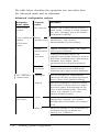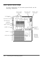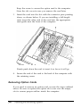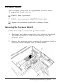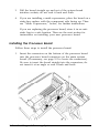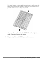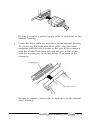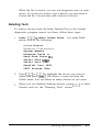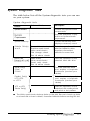
1
H
FCC COMPLIANCE STATEMENT
FOR AMERICAN USERS
This equipment has been tested and found to comply with the limits for a class B digital
device, pursuant to Part 15 of the FCC Rules. These limits are designed to provide
reasonable protection against harmful interference in a residential installation. This
equipment generates, uses, and can radiate radio frequency energy and, if not installed
and used in accordance with the instructions, may cause harmful interference to radio and
television reception. However, there is no guarantee that interference will not occur in a
particular installation. If this equipment does cause interference to radio and television
reception, which can be determined by turning the equipment off and on, the user is
encouraged to try to correct the interference by one or more of the following measures:
Cl Reorient or relocate the receiving antenna
0 Increase the separation between the equipment and receiver
Cl Connect the equipment into an outlet on a circuit different from that to which the
receiver is connected
;I Consult the dealer or an experienced radio/TV technician for help
WARNING
The connection of a non-shielded equipment interface cable to this equipment will
invalidate the FCC Certification of this device and may cause interference levels that
exceed the limits established by the FCC for this equipment. It is the responsibility of the
user to obtain and use a shielded equipment interface cable with this device. If this
equipment has more than one interface connector, do not leave cables connected to unused
interfaces.
Changes or modifications not expressly approved by the manufacturer could void the
user’s authority to operate the equipment.
FOR CANADIAN USERS
This digital apparatus does not exceed the Class B limits for radio noise emissions from
digital apparatus as set out in the radio interference regulations of the Canadian
Department of Communications.
Le present appareil numerique n’emet pas de bruits radioelectriques depassant les limites
applicables aux appareils numeriques de Classe B prescrites dans le reglement sur le
brouillage radioelectrique edicte par le Ministere des Communications du Canada.
User’s Guide
IMPORTANT NOTICE
Epson America, Inc., makes no representations or warranties, either express or implied, by
or with respect to anything in this manual, and shall not be liable for any implied
warranties of merchantability and fitness for a particular purpose or for any indirect,
special, or consequential damages. Some states do not allow the exclusion of incidental or
consequential damages, so this exclusion may not apply to you.
COPYRIGHT NOTICE
All rights reserved. No part of this publication may be reproduced, stored in a retrieval
system, or transmitted, in any form or by any means, electronic, mechanical,
photocopying, recording, or otherwise, without the prior written permission of Epson
America, Inc. No patent liability is assumed with respect to the use of information
contained herein. Nor is any liability assumed for damages resulting from the use of the
information contained herein. Further, this publication and features described herein are
subject to change without notice.
The power-on diagnostic error messages and error tone codes in Appendix C are copyright
1985-1989, Phoenix Technologies Ltd.
TRADEMARKS
Epson is a registered trademark and the EISA Series design is a trademark of Seiko Epson
Corporation.
General notice: Other product names used herein are for identification purposes only and
may be trademarks of their respective companies.
Copyright © 1991 by Epson America, Inc.
Torrance,Califomia
ii
Y739991001
Important Safety Instructions
1.
Read all of these instructions and save them for later reference.
2.
Follow all warnings and instructions marked on the computer.
3.
Unplug the computer from the wall outlet before cleaning. Use a
damp cloth for cleaning; do not use liquid or aerosol cleaners.
4.
Do not spill liquid of any kind on the computer.
5.
Do not place the computer on an unstable cart, stand, or table.
6.
Slots and openings in the cabinet and the back or bottom are
provided for ventilation; do not block or cover these openings.
Do not place the computer near or over a radiator or heat
register.
7.
Operate the computer using the type of power source indicated
on its label. If you are not sure of the type of power available,
consult your dealer or local power company.
8.
If you plan to operate the computer in Germany, observe the
following safety precaution:
To provide adequate short-circuit protection and over-current
protection for this computer, the building installation must be
protected by a 16 Amp circuit breaker.
Beim AnschulB des Computers an die Netzversorgung mut3
sichergestellt werden daB die Gebaudeinstallation mit einem
16 A ijberstromschutzschalter abgesichert ist.
9.
Connect all equipment to properly grounded (earthed) power
outlets. If you are unable to insert the plug into an outlet, contact
your electrician to replace your outlet. Avoid using outlets on
the same circuit as photocopiers or air control systems that
regularly switch on and off.
...
IIZ
10. Do not allow the computer’s cord to become damaged or frayed.
11. If you use an extension cord with the computer, make sure the
total of the ampere ratings of the devices plugged into the
extension cord does not exceed the ampere rating for the
extension cord. Also, make sure the total of all products plugged
into the wall outlet does not exceed 15 amperes.
12. You must extend the stabilizing feet on both sides of the
computer’s base whenever it is in an upright position to prevent
it from falling over.
13. Do not insert objects of any kind into this product through the
cabinet slots.
14. Except as specifically explained in this User’s Guide, do not
attempt to service the computer yourself. Refer all servicing to
qualified service personnel.
15. Unplug the computer from the wall outlet and refer servicing to
qualified service personnel under the following conditions:
A. When the power cord or plug is damaged.
B.
If liquid has entered the computer.
C. If the computer does not operate normally when the operating
instructions are followed. Adjust only those controls that are
covered by the operating instructions. Improper adjustment
of other controls may result in damage and often requires
extensive work by a qualified technician to restore the
computer to normal operation.
D. If the computer has been dropped or the cabinet has been
damaged.
E.
iv
If the computer exhibits a distinct change in performance.
Instructions Importantes de Skuriti!
1.
Lire completement les instructions qui suivant et les conserver
pour references futures.
2.
Bien suivre tous les avertissements et les instructions indiques sur
l’ordinateur.
3.
Debrancher l’ordinateur de toute sortie murale avant le nettoyage.
Utiliser un chiffon humide; ne jamais utiliser un nettoyeur
liquide ou une bonbonne aerosol.
4.
Ne jamais renverser un liquide d’aucune sorte sur l’ordinateur.
5.
Ne pas placer l’ordinateur sur un chariot, un support, ou une table
instable.
6.
Les events dans le meubles, a l’arriere et en dessous sont concus
pour l’aeration; on ne doit jamais les bloquer. Ne pas placer
l’ordinateur pres d’une source de chaleur directe.
7.
Le fonctionnement de l’ordinateur doit s’effectuer conformement
au type de source d’alimentation indiquee sur l’etiquette. Dans le
cas d’un doute de la source disponible, on doit communiquer
avec le concessionaire ou la compagnie d’electricite.
8.
Lorsqu’on desire utiliser l’ordinateur en Allemagne, on doit
observer les normes securitaires qui suivent:
Afin d/assurer une protection adequate a l’ordinateur contre les
court-circuits et le survoltage, l’installation de l/edifice doit
comprendre un disjoncteur de 16 amp.
9.
On doit brancher tout l’equipement dans une sortie reliee a la
masse. Lorsqu’il est impossible d’inserer la fiche dans la prise, on
doit retenir les services d’un electricien ou remplacer la prise. Ne
jamais utiliser une prise sur le m&me circuit qu’un appareil a
photocopie ou un systeme de controle d/aeration avec
commutation marche-arret.
V
10. S’assurer que le cordon d’alimentation de l’ordinateur n’est pas
effrite.
11. Dans le cas ou on utilise un cordon de rallonge avec l’ordinateur,
on doit s/assurer que la valeur totale d’amperes branches dans le
cordon n’excede en aucun temps les amperes du cordon de
rallonge. La quantite totale des appareils branches dans la prise
murale ne doit jamais exceder 15 amperes.
12. Sur chaque tote, l’ordinateur est muni de supports qu’il est
necessaire d’allonger lorsque l’appariel est mis en position
verticale, pour l’empecher de tomber.
13. Ne jamais inserer un objet de quelque sorte que ce soit dans les
cavites de cet appareil.
14. Sauf tel que specific dans la notice d’utilisation, on ne doit jamais
tenter d’effectuer une reparation de l’ordinateur. On doit referer
le service de cet appareil a un technicien qualifie.
15. Debrancher l’ordinateur de la prise murale et confier le service au
personnel de service qualifie selon les conditions qui suivent:
A. Lorsque le cordon d’alimentation ou la prise sont
endommages.
B. Lorsqu’un liquide s’est infiltre dans l’ordinateur.
C. Lorsque l’ordinateur refuse de fonctionner normalement
meme en suivant les instructions. N’ajuster que les
commandes qui sont enumerees dans les instructions de
fonctionnement. Tout ajustement inadequat de tout autre
controle peut provoquer un dommage et souvent necessiter
des reparations elaborees par un technicien qualifie afin de
remettre l’appareil en service.
D. Lorsqu’on a echappe l’ordinateur ou que l’on a endommage le
boitier.
E. Lorsque l’ordinateur demontre un changement note au niveau
de sa performance.
vi
Contents
Introduction
Optional Equipment . .
Software . . . . . . . . .
How to Use This Manual
Where to Get Help . . .
Chapter 1
.
.
.
.
.
.
.
.
.
.
.
.
.
.
.
.
.
.
.
.
.
.
.
.
.
.
.
.
.
.
.
.
.
.
.
.
.
.
.
.
.
.
.
.
.
.
.
.
.
.
.
.
.
.
.
.
.
.
.
.
.
.
.
.
.
.
.
.
.
.
.
.
.
.
.
.
.
.
.
.
.
.
.
.
.
.
.
.
Setting Up Your System
Preparing to Set Up the System . . . . . . . . . . . .
Installation Overview . . . . . . . . . . . . . . . . . .
Installing Optional Equipment . . . . . . . . . . . .
Connecting Peripheral Devices . . . . . . . . . . . .
Turning On the Computer . . . . . . . . . . . . . . .
Running the Change Country Code Utility . . . . .
Setting the Country Code for the First Time . .
Changing the Country Code . . . . . . . . . . .
Chapter 2
3
3
4
5
l-l
l-3
l-4
l-5
l-6
l-7
l-8
l-10
Running System Configuration
How to Use This Chapter . . . . . . . . . . . . . . . . . . . . . .
The Configuration Process . . . . . . . . . . . . . . . . . . . . .
Using Configuration Files . . . . . . . . . . . . . . . . . . .
Using the Keyboard . . . . . . . . . . . . . . . . . . . . . .
Using a Mouse . . . . . . . . . . . . . . . . . . . . . . . . .
Using On-line Help . . . . . . . . . . . . . . . . . . . . . .
Configuring Your System . . . . . . . . . . . . . . . . . . . . .
Starting the Program . . . . . . . . . . . . . . . . . . . . .
Setting the Date and Time . . . . . . . . . . . . . . . . . .
Performing the Configuration Steps . . . . . . . . . . . . .
2-2
2-3
2-3
2-4
2-4
2-5
2-6
2-6
2-8
2-9
vii
.Adding or Removing a Board . . . . . . . . . . .
Defining the Configuration Settings . . . . . . .
Using Advanced Configuration Options . . . . .
Using Alternate Configuration Files . . . . . . . . . .
Creating an Alternate SCI File . . . . . . . . . . .
Loading an Alternate SCI File . . . . . . . . . . .
Using Special Modes . . . . . . . . . . . . . . . . . . .
Using the SD Command . . . . . . . . . . . . . .
Using the CF Command . . . . . . . . . . . . . .
Copying the Configuration Files to a Hard Disk
Chapter 3
Using Your Computer
Extending the Stabilizing Feet . . . . . . . . . . . .
Locking the Computer’s Cover . . . . . . . . . . .
Using a Power-on Password . . . . . . . . . . . .
Changing or Deleting a Password . . . . . .
Using a Password in Network Server Mode .
Changing the Processor Speed . . . . . . . . . . .
Entering Keyboard Commands . . . . . . . .
Using the ESPEED Program . . . . . . . . . .
Parking the Hard Disk Drive Heads . . . . . . . .
Chapter 4
...
.
.
.
.
.
.
.
.
.
.
.
.
.
.
.
.
.
.
.
.
.
.
.
.
.
.
.
.
.
.
.
.
.
.
.
.
.
.
.
.
.
.
.
.
.
.
.
.
.
.
.
.
.
.
3-1
3-2
3-3
3-4
3-4
3-6
3-7
3-8
3-9
Accessing lnternal Components
Special Precautions . . . . . . . . .
Removing the Cover . . . . . . . .
Removing the Front Panel . . . .
Replacing the Front Panel . . . . .
Replacing the Cover . . . . . . .
Post-installation Setup Procedures
VlZZ
2-10
2-10
2-17
2-19
2-19
2-20
2-21
2-21
2-22
2-24
. . . . . . . . . . . . . . 4-1
.
.
.
.
.
.
.
.
.
.
.
.
.
.
.
.
.
.
.
.
.
.
.
.
.
.
.
.
.
.
.
.
.
.
.
.
.
.
.
.
.
.
.
.
.
.
.
.
.
.
.
.
.
.
.
.
.
.
.
.
.
.
.
.
.
.
.
.
.
.
4-3
4-4
4-5
4-6
4-8
Chapter 5
Installing and Removing Options
Main System Board Map . . . . . . .
Processor Board Maps . . . . . . . .
Option Cards . . . . . . . . . . . . . .
Installing an Option Card . . . .
Removing Option Cards . . . .
Processor Board . . . . . . . . . . . .
Removing the Processor Board .
Installing the Processor Board .
Math Coprocessor . . . . . . . . . . .
Installing a Math Coprocessor .
Removing a Math Coprocessor
Memory Modules . . . . . . . . . . .
Installing Memory Modules . .
Removing Memory Modules .
Chapter 6
.
.
.
.
.
.
.
.
.
.
.
.
.
.
.
.
.
.
.
.
.
.
.
.
.
.
.
.
.
.
.
.
.
.
.
.
.
.
.
.
.
.
.
.
.
.
.
.
.
.
.
.
.
.
.
.
.
.
.
.
.
.
.
.
.
.
.
.
.
.
.
.
.
.
.
.
.
.
.
.
.
.
.
.
.
.
.
.
.
.
.
.
.
.
.
.
.
.
.
.
.
.
.
.
.
.
.
.
.
.
.
.
. . . . . . .
. . . . . . .
. . . . . . .
. . . . . . .
. . . . . . .
. . . . . . .
. . . . . . .
. . . . . . .
. . . . . . .
. . . . . . .
. . . . . . .
. . . . . . .
. . . . . . .
. . . . . . .
Installing and Removing Disk Drives
Using the Correct Drive Bay . . . . . . . . . . . . . . . . . . . .
Setting the IDE Hard Disk Drive Jumpers . . . . . . . . . . . .
Changing the Jumper Settings . . . . . . . . . . . . . . . .
Installing or Removing a Drive in an Upper Bay . . . . . . . .
Removing a Drive . . . . . . . . . . . . . . . . . . . . . . .
Installing a Drive . . . . . . . . . . . . . . . . . . . . . . . .
Installing or Removing an Internal Drive . . . . . . . . . . . .
Removing the Internal Drive Housing . . . . . . . . . . .
Installing or Removing a Drive . . . . . . . . . . . . . . .
Reinstalling the Internal Drive Housing . . . . . . . . . .
Appendix A
5-2
5-3
5-4
5-5
5-6
5-7
5-7
5-8
5-9
5-9
5-10
5-11
5-13
5-14
6-2
6-3
6-4
6-6
6-7
6-9
6-13
6-14
6-16
6-18
Running System Diagnostics
Starting the Program . . . . . . . . . . . . . . . . . . . . . . . .
Deleting Tests . . . . . . . . . . . . . . . . . . . . . . . . .
Adding Tests . . . . . . . . . . . . . . . . . . . . . . . . . .
A-2
A-3
A-4
ix
Running Tests . . . . . . . . .
Resuming From an Error
System Diagnostic Tests . . .
Error Messages . . . . . . . .
.
.
.
.
.
.
.
.
Starting the Program . . . . . . . . . . . . .
Formatting a New Disk . . . . . . . .
Reformatting a Used Disk . . . . . . .
Selecting an Option . . . . . . . . . . .
Starting the Formatting Process . . . .
Option 1, Format . . . . . . . . . . . . . . .
Modifying the Defective Track Table
Formatting the Disk . . . . . . . . . .
Option 2, Destructive Surface Analysis . .
Option 3, Non-destructive Surface Analysis
Exiting the Program . . . . . . . . . . . . .
.
.
.
.
.
.
.
.
.
Appendix B
.
.
.
.
.
.
.
.
.
.
.
.
.
.
.
.
.
.
.
.
.
.
.
.
.
.
.
.
.
.
.
.
.
.
.
.
.
.
.
.
.
.
.
.
.
.
.
.
A-5
A-6
A-7
A-8
.
.
.
.
.
.
.
.
.
.
.
.
.
.
.
.
.
.
.
.
.
.
.
.
.
.
.
.
.
.
.
.
.
.
. .
.
.
.
.
.
.
.
.
.
.
.
.
.
.
.
.
.
.
.
.
.
.
.
.
.
.
.
.
.
.
.
.
.
.
.
.
.
.
.
.
.
.
.
.
. . . . . .
. . . . . .
. . . . . .
. . . . . .
. . . . . .
. . . . . .
. . . . . .
. . . . . .
. . . . . .
. . . . . .
. . . . . .
B-2
B-3
B-4
B-4
B-4
B-5
B-7
B-8
B-9
B-11
B-12
. . . . . . . . . . . . . . .
. . . . . . . . . . . . . . .
. . . . . . . . . . . . . . .
. . . . . . . . . . . . . . .
. . . . . . . . . . . . . . .
. . . . . . . . . . . . . . .
. . . . . . . . . . . . . . .
. . . . . . . . . . . . . . .
. . . . . . . . . . . . . . .
. . . . . . . . . . . . . . .
. . . . . . . . . . . . . . .
. . . . . . . . . . . . . . .
. . . . . . . . . . . . . . .
. . . . . . . . . . . . . . .
. . . . . . . . . . . . . . .
C-1
C-2
C-5
C-9
C-11
C-11
C-12
C-13
C-14
C-15
C-16
C-16
C-17
C-18
C-18
Formatting a Hard Disk
Appendix C Troubleshooting
Identifying Your System .
Error Messages . . . .
Power or Lock-up Problems
Password Problems . . .
Keyboard Problems . . . . .
Monitor Problems . . . . . .
Diskette Problems . . . . .
Diskette Drive Problems . .
Hard Disk Problems . . . .
Software Problems . . . . .
Printer Problems . . .
Option Card Problems . . .
Memory Module Problems
Mouse Problems . . . . . .
Math Coprocessor Problems
X
.
.
.
.
.
.
.
.
.
.
.
.
.
.
.
.
.
.
.
.
.
.
.
.
.
.
.
.
.
.
.
.
.
.
.
.
.
.
.
.
.
.
.
.
.
.
.
.
.
.
.
.
.
.
.
.
.
.
.
.
.
.
.
.
.
.
.
.
.
.
.
.
.
.
.
Appendix D Specifications
Main System Board . . . . . .
Interfaces . . . . . . . . . . . .
Controllers . . . . . . . . . . .
Processor Board . . . . . . . .
Mass Storage Bays . . . . . . .
Power Supply . . . . . . . . .
Keyboard . . . . . . . . . . . .
Environmental Requirements
Physical Characteristics . . . .
Power Source Requirements .
System Memory Map . . . . .
.
.
.
.
.
.
.
.
.
.
.
.
.
.
.
.
.
.
.
.
.
.
.
.
.
.
.
.
.
.
.
.
.
.
.
.
.
.
.
.
.
.
.
.
.
.
.
.
.
.
.
.
.
.
.
.
.
.
.
.
.
.
.
.
.
.
. . . . . . . . . .
. . . . . . . . . .
. . . . . . . . . .
. . . . . . . . . .
. . . . . . . . . .
. . . . . . . . . .
. . . . . . . . . .
. . . . . . . . . .
. . . . . . . . . .
. . . . . . . . . .
. . . . . . . . . .
D-1
D-1
D-2
D-3
D-3
D-4
D-5
D-5
D-5
D-6
D-7
Glossary
Index
xi
Tables
Key commands . . . . . . . . . . . . . . . . . . . . . . . 2 - 4
System board options . . . . . . . . . . . . . . . . . . . 2-11
Default non-cache address blocks . . . . . . . . . . . . 2-14
Hard disk drive types . . . . . . . . . . . . . . . . . . . 2-15
Advanced configuration options . . . . . . . . . . . . . 2-18
SD command parameters . . . . . . . . . . . . . . . . . 2-22
CF command parameters . . . . . . . . . . . . . . . . . 2-23
Keyboard speed setting commands . . . . . . . . . . . 3-7
ESPEED program parameters . . . . . . . . . . . . . . . 3-9
Option slot power limits . . . . . . . . . . . . . . . . . . 5-4
SIMM description . . . . . . . . . . . . . . . . . . . . . . 5-12
Example SIMM configurations . . . . . . . . . . . . . . 5-12
Hard disk drive jumper settings . . . . . . . . . . . . . 6-5
System diagnostic tests . . . . . . . . . . . . . . . . . . A-7
System diagnostic error messages . . . . . . . . . . . . A-8
Power-on diagnostic error messages . . . . . . . . . . . C-3
Power-on diagnostic error tone codes . . . . . . . . . . C-3
Maximum outputs . . . . . . . . . . . . . . . . . . . . . D-4
Option slot power limits . . . . . . . . . . . . . . . . . . D-4
Environmental requirements . . . . . . . . . . . . . . . D-5
120-Volt power source requirements . . . . . . . . . . . D-6
240-Volt power source requirements . . . . . . . . . . . D-6
xii
The Epson® EISA Series computer is a powerful, versatile
system ideally suited for use as either a network server or a
high-performance personal workstation. It incorporates the
latest EISA (Extended Industry Standard Architecture)
technology into a convenient tower design. Its exceptional
features and flexibility enable you to use the most advanced
peripheral devices and software while maintaining full
compatibility with ISA technology. Your system includes the
following features:
4MB of RAM on single inline memory modules (SIMMs)
SIMM sockets for installing up to 64MB of memory using
1MB, 2MB, 4MB, or 8MB SIMMs
8KB of extended CMOS RAM for EISA configuration
information
Upgradable processor board providing high speed cache
memory and math coprocessor support
One built-in parallel and two built-in serial interfaces
IBM ® PS/2 ® compatible mouse port and keyboard port
Eight EISA expansion slots (compatible with 32-bit EISA
cards and 8- or 16-bit ISA cards)
IDE hard disk drive interface (for two hard disk drives)
Diskette drive controller (for two diskette drives and one
tape drive)
Six half-height mass storage bays: two internal bays and
four externally-accessible bays.
lntroduction 1
The built-in interfaces let you connect basic peripheral devices
(such as a printer and mouse) directly to the computer, leaving
the expansion slots for optional devices such as a SCSI adapter
or a networking card.
Your computer’s EISA technology allows the 32-bit processor
to access certain I/O expansion boards 32 bits at a time when
running appropriate software. In addition, the EISA burst mode
capability enables data transfers of up to 33MB of data per
second through the EISA bus.
The powerful EISA configuration program automatically
configures any EISA boards you install and provides all the
necessary information for configuring ISA boards. The result is
a configuration that manages your system resources in the most
efficient manner possible.
The EISA Series computer offers several other features to
enhance system performance:
2
Cl
Automatic shadow RAM support. This speeds up access to
the system and video BIOS.
U
Processor speed simulation support. You can set the
processor to emulate a variety of system speeds from
8 MHz up to your processor’s highest speed to provide
compatibility with a wide variety of software.
Ll
Password security. You can set a password in either regular
or network server mode.
Introduction
Optional Equipment
By adding SIMMs to the main system board, you can expand
the computer’s memory up to 64MB.
On the upgradeable processor board, you can install a math
coprocessor or another coprocessor, depending on the board
you have.
You can also install a variety of other options, such as diskette
drives, hard disk drives, a tape drive, or a SCSI subsystem.
Check with your authorized Epson dealer to see which options
are available.
Software
Your system comes with three diskettes (Reference 1, 2, and 3)
containing the following software:
U
EISA System Configuration program
c1
ISA configuration files for popular ISA boards
LI System diagnostics program
U
Hard disk drive low-level formatting utility
tl
HDDPARK program to park the hard disk drive
read/write heads
LI
ESPEED program to change the processor simulation speed
tl
CHGCTR program to set country-dependent keyboard and
configuration information.
Introduction 3
How to Use This Manual
This manual explains how to set up, configure, and operate
your computer, as well as how to install options and run
diagnostic tests. It does not cover your operating system; see
your operating system manual for instructions on installing
and using it.
Although you should be sure to follow the steps in Chapter 1
and Chapter 2 to set up and configure your system, you do not
need to read everything in this book. See the following chapter
summaries to find the sections you need.
Chapter 1 provides instructions for setting up your system.
Chapter 2 describes how to run the System Configuration
program to configure your computer.
Chapter 3 provides instructions for certain operating
procedures, such as locking the computer’s cover, using a
password, and changing the operating speed.
Chapter 4 describes how to remove and replace the cover and
front panel to access the internal components.
Chapter 5 describes how to install and remove options.
Chapter 6 describes how to install and remove disk drives.
Appendix A outlines the system diagnostic tests.
Appendix B gives instructions for performing a hardware-level
format on a hard disk.
Appendix C contains troubleshooting tips.
Appendix D gives the technical specifications for the computer.
At the end of the manual, you’ll find a glossary and an index.
4
Introduction
Where to Get Help
If you purchased your computer outside of the United States,
please contact your dealer or the marketing location nearest
you for customer support and service. International marketing
locations are listed on the inside of this manual’s back cover.
If you purchased your Epson product in the United States,
Epson America provides local customer support and service
through a nationwide network of authorized Epson dealers and
Service Centers.
Epson also provides the following support services through the
Epson Customer Resource Center at (800) 922-8911:
cl
Technical assistance with the installation, configuration,
and operation of Epson products
cl
Assistance in locating your nearest Authorized Epson
Reseller or Service Center
u
Sales of ribbons, supplies, parts, documentation, and
accessories for your Epson product
cl
Customer Relations
u
Epson technical information library fax service
cl
Product literature with technical specifications on our
current and new products.
Introduction 5
Chapter 1
Setting Up Your System
This chapter describes the basic steps you perform to
set up your system for the first time. It defines the system
requirements and gives a general outline of the steps you need
to follow to start using your computer. It also describes how to
set the appropriate country code for the system’s keyboard and
configuration information.
Preparing to Set Up the System
Before you set up your system, be sure to read “Important
Safety Instructions” at the beginning of this manual (before the
table of contents). These instructions provide information about
properly caring for your computer and operating it correctly.
It is important to choose a safe, convenient location for your
system that provides the following:
CI
A flat, hard surface. Surfaces like carpeted floors attract
static electricity, which can erase data on your disks,
damage the computer’s circuitry, and prevent proper
ventilation. Place the computer on an anti-static mat if the
surface is carpeted.
Q
Good air circulation. Leave several inches of space around
the computer so air can move freely.
Cl
Moderate environmental conditions. Select a cool, dry area
and protect your computer from extremes in temperature,
humidity, dust, and smoke. Avoid direct sunlight or any
other source of heat.
Setting Up Your System
Z-1
CI
No electromagnetic interference. Do not place your system
too close to any electrical device, such as a telephone, that
generates an electromagnetic field.
Cl
Appropriate power sources. Connect all your equipment to
the appropriate power source. See “Power Source
Requirements” in Appendix D for more information.
Ll
Extend the stabilizing feet. You must extend the feet on
both sides of the computer’s base whenever it is in an
upright position to prevent it from falling over.
7
Remove the protector card. If you have a 5Winch diskette
drive, be sure to remove the protector card from the
diskette slot. This card is inserted at the factory to protect
the read/ write heads in the drive.
You should place your computer next to or under your desk, as
shown below. This leaves more room on top of your desk for
other devices, such as the monitor, keyboard, and printer.
1-2
Setting Up Your System
Installation Overview
Listed below are the general steps you follow to install options,
connect peripheral devices, and configure your system. For
detailed instructions on performing these steps, see the
appropriate sections specified in the overview.
1.
Install any optional equipment you want to add to your
computer, such as disk drives, a math coprocessor, memory
modules, or EISA option cards. Do not install any ISA
option cards yet (unless you will be using an ISA card to
control your monitor). See “Installing Optional Equipment”
below.
2.
Connect a monitor, a printer, the keyboard, and a mouse, if
you are going to use one. See “Connecting Peripheral
Devices” below.
3.
Then see “Turning On Your Computer,” below, before you
turn on the system.
4.
Run the Change Country Code utility (CHGCTR) to install
the correct keyboard driver and configuration information
for your system. See “Running the Change Country Code
Utility,” below, for instructions.
5.
Read “The Configuration Process” in Chapter 2 to familiarize
yourself with the use of the System Configuration program.
6.
Run the System Configuration program, as described in
Chapter 2, to configure your system.
7.
Turn off the system, unplug all the power cords, and
disconnect any peripheral devices from the computer.
8.
Set any switches or jumpers on your ISA cards, if necessary,
and install them in the computer. See Chapter 5 for
instructions on installing option cards.
Setting Up Your System
1-3
9.
Connect all of your peripheral devices.
10. Install your operating system and any other application
programs.
Installing Optional Equipment
The first time you set up your computer, you should install any
disk drives, math coprocessor, memory modules, or EISA
option cards you plan to use. Do not install any ISA option
cards yet, unless you will be installing a video adapter on an
ISA option card to control your monitor.
You can install the rest of your ISA cards after you run the
System Configuration program. This program provides
information about the jumper and switch settings for the ISA
option cards you will install.
Follow the instructions in Chapters 5 and 6 to install optional
equipment in your computer. Be sure to check your computer’s
option slot power limits on page 5-4 before you install any
option cards.
You may need to unlock the computer’s cover to access the
internal components. See Chapter 3 for instructions.
When you are finished installing optional equipment, return to
this chapter for guidelines on connecting the peripheral devices
necessary to run the System Configuration program.
1-4
Setting Up Your System
Connecting Peripheral Devices
You may not want to connect all your peripheral devices before
you run the System Configuration program for the first time. If
you’ll be installing ISA cards after running the program, you
may want to connect only those devices necessary to perform
the program’s functions. If you connect other devices, you will
need to disconnect them later to install the ISA cards.
You must connect a monitor and a keyboard to run the System
Configuration program. You may also want to connect a
printer and a mouse.
As you set up your computer, leave this manual’s back cover
foldout open so you can refer to the illustrations identifying the
different parts of the computer.
The following icons mark the built-in interfaces on the back of
the computer:
mouse icon
keyboard
icon
serial icons
parallel icon
Caution
Although the keyboard and mouse ports are physically
identical, you cannot use them interchangeably. Be sure to
plug the keyboard and the mouse into the correct ports.
Setting Up Your System
1-5
Before connecting your peripheral devices, make sure the
power buttons or switches on the computer and all the
peripheral devices are turned off. Then connect the devices in
the following order:
1.
Connect your peripheral device cables to the computer.
2.
Connect the power cords to the computer and other devices,
if necessary.
3.
Plug the power cords into their electrical outlets.
Be sure to read the next section before you turn on your
computer.
Turning On the Computer
After you set up your system, you’re ready to turn on the
power. But first, read the following safety rules to avoid
accidentally damaging your computer or injuring yourself:
1-6
Lt
Do not connect or disconnect any power or peripheral
device cables when the computer’s power is on.
LI
Never turn on the computer with a protector card in the
diskette drive.
CI
Never turn on the computer when its cover is off.
D
Never turn off or reset your computer while a disk drive
light is on. This can destroy data stored on disk.
CI
Always wait at least five seconds after you turn off the
power before you turn it on again. This allows the
computer to clear and reset its memory.
Setting Up Your System
tl
Do not leave a beverage near your system or any of its
components. Spilled liquid can damage the circuitry of
your equipment.
Cl
Always turn off the power, disconnect the computer’s
power cord, and wait 30 seconds before you remove the
cover. Only remove the cover to access internal devices.
Now you can run the Change Country Code utility, as
described below.
Running the Change Country Code Utility
Before you configure your computer or perform any other
operations, you need to create new AUTOEXEC.BAT and
CONFIG.SYS files for your country on the Reference 1 diskette.
You do this by running the Change Country Code utility.
This utility creates files that contain the appropriate keyboard
driver and configuration information for the country you select.
The program runs automatically the first time you boot your
computer from the Reference 1 diskette.
Country codes are available for the following countries:
Cl United States
Ll United Kingdom
LI F r a n c e
Ll G e r m a n y
Ll I t a l y
tl S p a i n .
Setting Up Your System
1-7
The default country code is United States. See the instructions
in the next section to set the appropriate country code. Later, if
you need to change the country code, follow the instructions
under “Changing the Country Code” on page l-10.
Setting the Country Code for the First Time
To run the Change Country Code utility the first time you boot
your computer from the Reference 1 diskette, follow these steps:
1.
Insert the Reference 1 diskette in drive A.
2.
Turn on your computer or press the RESET button.
3.
After a moment, you see a screen describing the Change
Country Code utility. The screen displays the following
message and prompt:
Current country code
is
United
States.
Change country code? (Y/N)
If you want to select the default country code, United States,
press [Nl. You see a message telling you that the program
still must update your files. Then the program copies the
files. Go to step 4.
If you want to select another country code, press m. You see
the following:
Press F1 - US Version (United States)
P r e s s F 2 - UK Version (United Kingdom)
Press F3 - FR Version (French)
Press F4 - GR Version (German)
Press F5 - IT Version (Italian)
Press F6 - SP Version (Spanish)
Press any other key to accept the
current country code.
1-8
Setting Up Your System
Press the appropriate function key for your country. The
program copies the files and displays a message confirming
the change.
4.
When you see the following message, press any key to reboot
the system and run the System Configuration program:
you should reboot the system to r u n
the appropriate AUTOEXEC.BAT and
CONFIG.SYS files and start the System
Configuration program.
N OW
Press any key to reboot . . .
After a moment, you see the System Configuration program
title screen. If you want to run that program now, see the
information in Chapter 2 before you begin.
If you do not want to configure your computer now, remove
the diskette from drive A and turn off your computer.
The AUTOEXEC.BAT and CONFIG.SYS files on your
Reference 1 diskette are now customized for your country’s
keyboard and configuration information. Whenever you boot
your system from the Reference 1 diskette, the computer runs
the appropriate files for your country.
Also, when you run the System Configuration program, the
format of the date and time in your computer’s real-time clock
will be set to the appropriate format for your country.
Setting Up Your System
1-9.
Changing the Country Code
If you need to change the country code for your system’s
keyboard driver and configuration information, you can run
the CHGCTR utility. Follow these steps:
1.
Insert the Reference 1 diskette in drive A and log onto
drive A.
2.
At the A> prompt, type CHGCTR and press [Enter]. You see the
information screen for the Change Country Code utility
followed by this prompt:
Change country code? (Y/N)
3.
If you want to keep the current country code, press [Nl. You
see a message telling you that the program still must
update your files. Then the program copies the files. Go to
step 4.
If you want to select another country code, press m. You
see the following:
Press F1 - US Version (United States)
Press F2 - U K V e r s i o n ( U n i t e d K i n g d o m )
Press F3 - FR Version (French)
Press F4 - GR Version (German)
Press F5 - IT Version (Italian)
Press F6 - SP Version (Spanish)
Press any other key to accept the
current country code.
Press the appropriate function key for the country code you
want. The program copies the files and displays a message
confirming the change.
1-10
Setting Up Your System
4.
When you see the following message, press any key to reboot
the system and run the System Configuration program:
Now you should reboot the system to run
the appropriate AUTOEXEC.BAT and
CONFIG.SYS files and start the System
Configuration program.
Press any key to reboot . . .
After a moment, you see the System Configuration title screen.
If you want to run that program now, see Chapter 2 for
instructions.
If you do not want to run System Configuration, remove the
Reference 1 diskette from drive A and turn off your
computer.
The AUTOEXEC.BAT and CONFIG.SYS files on your
Reference 1 diskette are now customized for the country you
selected.
Also, when you run the System Configuration program, the
format of the date and time in your computer’s real-time clock
will be set to the appropriate format for the country you
selected.
Setting Up Your System
1-11
Chapter 2
Running System Configuration
The System Configuration program, provided with your
system on the Reference 1 diskette, allows you to configure
your computer. Use the program to do the following:
Ll
Learn about the configuration process
cl
Set the date and time
cl
Copy the configuration (CFG) files for any option cards you
install
cl
Configure the system board and any option cards
cl
Create one or more System Configuration Information
(SCI) files
II
Access other system utilities, such as System diagnostics
and hard disk utilities.
You must run the System Configuration program to configure
your system before you can use your computer for any other
purpose. You may need to run it again later if you add or
remove options, such as memory, disk drives, or option cards.
After running the program, you save your current
configuration in the computer’s CMOS and in a file called
SYSTEM.SCI. Your computer checks this information each time
you turn it on and assigns your system resources based on the
configuration options you selected.
If you want to create an alternate configuration file for your
computer or another computer, you can create an alternate SC1
file. See page 2-19 for more information.
Running System Configuration
2-l
Note
The first time you configure your computer, you must run
the program from the Reference 1 diskette and it is best to
always run it from there.
How to Use This Chapter
This chapter is divided into the following four sections:
The Configuration Process describes the various aspects of
configuring your computer using the System Configuration
program. It also tells you how to use the keyboard or a
mouse with the program and how to use on-line help.
Configuring Your System provides step-by-step
instructions for running the System Configuration program
and is organized in the order in which you should perform
the operations.
Using Alternate Configuration Files tells you how to
create and use alternate configuration files, should you find
it necessary to do so.
Using Special Modes tells you how to configure your
computer by running it in special operating modes, such as
non-target modeling mode.
Read “The Configuration Process” first to familiarize yourself
with all aspects of the configuration process. Then perform the
configuration operations in the order they are described under
“Configuring Your System.”
If you need to create alternate configuration files or run the
program in special modes, see pages 2-19 or 2-21, respectively.
2-2
Running System Configuration
The Configuration Process
This section describes the following configuration operations:
LI
Using the configuration files
Ll
Using the keyboard or a mouse with the program
3
Using on-line help.
Using Configuration Files
Configuration (or CFG) files provide information to the system
about a card’s functions and resource requirements so your
computer can allocate its resources efficiently. They also
provide instructions for setting any switches and jumpers on
ISA cards.
You copy to your Reference 1 diskette a configuration file for
each card you install using the System Configuration program.
EISA cards come with the necessary CFG file to allow the
program to configure the card automatically. See your EISA
card documentation for more information.
ISA option cards may come with the necessary CFG file for this
program. If not, Epson provides many ISA configuration files
on the Reference 3 diskette. You can also write to the
manufacturer of your option card and request a CFG file for it.
Use the file provided by your ISA card manufacturer, if
possible, and do not copy more than one file for a card.
If you do not have a configuration file for your ISA card, you
can still install the card in your system. However, you should
configure the rest of your system and then follow the
instructions that came with the card to set any of its switches or
jumpers.
Running System Configuration
2-3
Using the Keyboard
If you use a keyboard when you run the System Configuration
program, refer to the table below for a description of the keys
you can use to move the cursor and select items. If you’ll be
using a mouse with the program, see “Using a Mouse” below.
Most of the screens show which keys you can press to perform
various operations. Follow the instructions on each screen.
Whenever the <OK> icon is highlighted, press [ to select
<OK>. To select the <Cancel> icon, you can either press the
m key or highlight <Cancel> and press B.
Key commands
@J or m
Moves the cursor to the next field
[shnlmorm
Moves the cursor to the previous field
Highlights items within a list or scrolls the screen
Selects the highlighted option
I
[
Cancels the current action or menu
Moves the cursor up or down one screen
Moves the cursor to the first line of information
mm
Moves the cursor to the last line of information
Using a Mouse
The first time you run System Configuration, you must use the
keyboard. After configuring your system, load your operating
system and then install your mouse driver. Then you can run
System Configuration using your mouse.
2-4
Running System Configuration
To select most options, place the cursor on the option and click
the left button once to highlight it and again to select it.
When you see Ir] or m on the screen, you can scroll the
text. Place the cursor on the arrow indicating the scroll
direction and hold down the left button. Release it to stop.
Keep in mind that this chapter gives keyboard instructions
when describing how to use the System Configuration
program. You should substitute the appropriate mouse
equivalents when performing the same operations.
Using On-line Help
The System Configuration program provides extensive on-line
help information. You can obtain help in the following ways:
Cl
Highlight a menu option to see a description of its function.
tl Select Step 1: Important EPSON EISA
configuration information for detailed information
about each step in the configuration process.
Cl
Press the m key whenever you see Help=Fl. The
following menu appears:
EPSON EISA Configuration Help
Current screen
Selected item or board
All boards
Keys
Using help
EPSON EISA configuration
Press m to select the help information you need; then press
I.
Running System Configuration
2-5
Configuring Your System
Follow the instructions in this section and on your screen to
configure your computer using the System Configuration
program. You configure your system in the following order:
Ll
Set the date and time
Ll
Add or remove boards; when you add an option card, the
program copies the necessary configuration files
Ll
View or edit the details of your configuration; use this
selection to define your configuration options
3
View your jumper and switch settings
LI
Save the configuration as you exit the program.
Starting the Program
Follow these steps to start the System Configuration program
from the Reference 1 diskette:
1.
Insert the Reference 1 diskette in drive A and turn on or reset
the computer.
Note
If you installed any EISA option cards in your system,
you see a message telling you to run the configuration
program. Press I to continue.
2.
2-6
After a moment, you see the title screen for the System
Configuration program. Press any key to continue. You see
the Welcome screen.
Running System Configuration
3.
Press IEnter You see the Main Menu:
Main Menu
Learn about configuring your computer
Configure computer
Set date
Set time
Access to other utilities
Maintain system configuration diskette
Exit from this utility
Note
If you installed any EISA option cards in your system,
the program firstasks you to insert a diskette containing
a CFG file for the EISA card. Remove the Reference 1
diskette, insert the appropriate configuration diskette,
and press [Enter. Follow the instructions on the screen to
complete the installation process and then go to step 4.
4.
For an overview of the configuration process, highlight
Learn about configuring your computerand
press [Enter]. When you have finished reading the three
Help screens, press m to return to the Main Menu.
(You can press m to return to the Main Menu at any
time.)
Now set the date and time of your computer’s real-time clock,
as described below.
Running System Configuration
2-7
Setting the Date and Time
The real-time clock in your computer continuously tracks the
date and time-even when the computer is turned off. The first
time you run the configuration program, set the date and time
for your computer. You can set them again later to adjust your
clock for seasonal time adjustments, such as daylight savings
time. The computer automatically changes the date for leap
years.
Follow these steps to set the date and time:
1.
At the Main Menu, select Set date. You see a prompt such
as the following:
Set Date
Date 06-08-1992 (mm-dd-yyyy)
Note
The format for the date and time may look different from
the prompts shown here, depending on the country code
you chose when you ran the Change Country Code
utility. (See Chapter 1 for more information.)
2.
The current setting for Date is highlighted. Correct it as
necessary. You can use the arrow keys to move the cursor
and overtype the date. Then press [Enter.
3.
At the Main Menu, select Set time. You see a prompt
similar to the Set Date prompt.
4.
Type the current time and press I. You see the Main
Menu.
Now you can configure your computer, as described below.
2-8
Running System Configuration
Performing the Configuration Steps
Follow these steps to configure your computer:
1.
At the Main Menu, select Configure computer. You see
this menu:
S t e p s i n configuring your computer
Step 1:
Step
Step
Step
Step
2:
3:
4:
5:
Important EPSON EISA
configuration information
Add or remove boards
View or edit details
Examine required switches
Save and exit
2.
Select Step 1 and read the information displayed on your
screen about configuring your system. If you want to print
any of the screens, press the [-Screen_] key.
3.
Select Step 2 and follow the instructions on the screen to
add, remove, or move option cards in your configuration
and copy any necessary CFG files to your Reference 1
diskette. See the next section for more information.
4.
Select Step 3 and follow the instructions on the screen to
view or edit the details of your option cards and your
system board. See “Defining the Configuration Settings”
below for more information.
5.
Select Step 4 if you want to view the switch or jumper
settings you may need to change on any ISA cards you will
install. Follow the instructions on the screen.
6.
When you are finished configuring your system, select
Step 5 to save the configuration in your computer’s
CMOS and reboot the system. You can also exit the
program without saving the configuration, if necessary.
Follow the instructions on the screen.
Running System Configuration
2-9
Adding or Removing a Board
Select Step 2: Add or remove boards when you need to
add or remove an option card. The program displays a list of
the computer’s slots with a description of any boards or cards
that it detects. The computer automatically detects EISA cards,
but you must add the necessary ISA card information. Follow
the instructions on the screen to add, move, or remove an
option card.
When you add an option card, you need the configuration
diskette that came with the card. Follow the instructions on the
screen to copy the appropriate CFG files to your Reference 1
diskette.
Defining the Configuration Settings
Select Step 3: View or edit details from the
configuration menu to view your system configuration options.
Follow the instructions on the screen to edit the functions of
these options or to change their resource assignments. You can
also perform various advanced configuration operations by
accessing the Advanced menu. See “Using the Advanced
Configuration Options,” later in the chapter, for more
information.
You cannot change the settings for certain options because they
are detected and set automatically by the program. Some
options or settings may not be available, depending on the
processor board you have installed.
If you add any EISA option cards to your system, various
configuration options for the card(s) appear on the screen
beneath the system board options. See your EISA option card
documentation for information about configuring your card(s).
2-10
Running System Configuration
The table below describes the settings available for each of the
system board options.
System board
options
r
Option
Settings
Memory
remap
control
(384KB)
Enabled
Disabled
Sets the status of the unused
memory between the 640KB
and 1 MB addresses. (The
amount of unused memory is
dependent on shadow RAM.)
Set to Enabled to remap this
memory to the top of the
extended memory area; set to
Disabled (default) to leave it at
its original address.
Base
memory
640KB
Setting is always 640KB
Internal
extended
memory
(memory size)
Automatically set to the
amount of internal extended
memory (on SIMMs) detected
in your system
External
extended
memory
(memory size)
Automatically set to the
amount of external extended
memory (on card) detected in
your system
Total
extended
memory
(memory size)
Automatically set to the total
amount of extended memory
detected in your system
User-defined
non-cache
area
Disabled
Enabled (addresses1
See “Non-cache areas” below
User-defined
external
BIOS
shadow
area
Disabled
Enabled (addresses)
Sets up to three, 16KB shadow
RAM address blocks in the
external BIOS range C800h to
EC00h to contain a copy of
the external BIOS information
Running System Configuration
2-11
System board options (continued)
t
Option
Settings
Description
Video BIOS
shadow
Enabled
Disabled
Set to desired status of video
BIOS shadow RAM: for video
controllers with a BIOS (VGA or
EGA), you can enable shadow
RAM; for controllers without a
BIOS (CGA, etc.), shadow RAM
is automatically disabled
Display
adapter
Me
CGA 40 column
CGA 80 column
Monochrome 80 column
EGA
VGA
MCGA
Other
Automatically set to the type
of display adapter card
installed
BIOS version
[version number)
Automatically set to the version
number detected in your
system
Processor
tVw
(processor type)
Automatically set to the
processor board type
detected in your system
(coprocessor type)
Automatically set to the
numeric coprocessor type
detected in your system
Power-on
simulation
speed
High speed (native)
Auto speed during FDD
access
16 MHz 386SX simulation
20 MHz 386SX simulation
25 MHz 386DX simulation
33 MHz 386DX simulation
25 MHz 486DX simulation
Low speed (simulated
8 MHz speed)
Set to the appropriate speed
for your system and
applications; available
simulation speeds vary,
depending on the type of
processor board installed
System BIOS
update
Disabled
Enabled
Set to Enabled to allow
updating of CPU-dependent
BIOS information from diskette;
default setting is Disabled
System
cache
scheme
Write-thru
Automatically set to the cache
type detected in your system;
available settings may vary
c
Numeric
coprocessor
Me
L
2-12
Running System Configuration
System board options (continued)
Option
Settings
Power-on
password
Not installed
Installed
to the system
Off
On
Turn on to provide special
password security when the
system operates as a network
server; password must be
installed to turn on this mode
Enabled at power-on
Disabled at power-on
Set to desired initial num lock
status when system is turned on
or reset
Keyboard
repeat rate
Fast
Normal
Slow
Set to desired speed of
keyboard repeat rate when a
key is pressed
Speaker
volume
control
High
Medium
Low
Off
Set to the desired speaker
volume or turn the speaker off
Built-in
mouse port
Enabled
Disabled
Set to Enabled to use the
built-in mouse port; set to
Disabled to use a mouse with a
port on an option card
L
Built-in
serial port A
Disabled
COM 1 (3F8h)
COM2 (2F8h)
Built-in
serial port B
Disabled
COM2 (2F8h)
Built-in
parallel port
Disabled
LPT1 (3Bch)
LPT2 (378h)
LPT3 (278h)
c
1
Set to desired setting for the
first built-in port; BIOS disables
port if it detects conflicting
port(s) on option card(s)
Set to desired setting for the
second built-in port; BIOS
disables port if first serial port is
set to COM2 or if it detects
conflicting port(s) on option
card(s)
Set to desired setting for built-in
port; BIOS disables port if it
detects conflicting port(s) on
card(s)
i option
Running System Configuration
2-13
System board options (continued)
Option
Diskette
drives A
and B
Embedded
~hard disk
controller
Hard disk
drives C
and D
Settings
1 Not installed
360KB (5.25 inch)
1.2MB (5.25 inch)
720KB (3.5 inch)
1.44MB (3.5 inch)
I
Description
Set to type of diskette drive(s)
assigned as drives A and B;
BIOS disables the built-in
diskette drive controller if it
detects a conflicting controller
on an option card
Enabled
Disabled
Set to the desired setting for
the built-in IDE controller; BIOS
disables the built-in controller if
it detects a conflicting
controller on an option card
Not installed
User defined
Type (1 to 64)
Set to the type of hard disk
drives installed as drives C and
D or select User defined (see
“Hard disk drive types” below)
Non-cache areas
Your computer automatically caches all of your memory except
for the six non-cache memory blocks listed in the table below.
You can define up to three additional, 16KB, non-cache
memory blocks by selecting the User defined non-cache area(s)
option and entering the block addresses. For example, if you
install a network or bus-mastering option card, such as a SCSI
controller, you should set the address blocks used by these
boards as non-cache blocks to avoid any memory conflicts.
Default non-cache address blocks
2-24
Address range (hex)
Function
A0000 through AFFFF
EGA or VGA video memory
BOO00 through BFFFF
MDA or CGA video memory
COO00 through C7FFF
VGA BIOS (RAM shadow area)
C8000 through DFFFF
Adapter ROM area
E0000 through EFFFF
Adapter ROM area
F0000 through FFFFF
System BIOS ROM
Running System Configuration
Hard disk drive types
The following table lists the types of hard disk drives you
can use in your computer. Check this table and the manual that
came with your hard disk to find the correct type for the hard
disk drive(s) installed in your computer. Then select that type
at the hard disk drive Type prompt. If you do not find your
drive type in the table, select User defined and enter your
drive’s parameters.
Hard disk
drive types
Drive name
Cylinders Heads Sectors Precomp Landing MB
zone
01
04
I ST-506
1
306
ST-506
4
17
128
~4
I17
i 300
6
17
300
17
i512
940
,8
17
1512
17
I-
f
I
No hard disk
,305
10.2
615
20.4
tI
940
46.8
615
20.4
511
30.7
733
30.4
901
112.1
06
ST-506
07
ST-506
08
ST-506
09
ST-506
900
15
17
10
ST-506
820
3
17
820
20.4
11
ST-506
855
5
17
855
35.5
12
ST-506
855
7
17
-
855
49.7
13
ST-506
306
8
17
128
319
20.3
733
7
17
733
42.6
612
4
17
0
663
20.3
977
5
17
300
977
40.5
t
T 17
L
256
17
-
(1)
c
c
tI
c
c
1
14
ST-506
t
reserved
Seagate
9420551
977
7
17
-
977
56.8
1024
7
17
512
1023
59.5
733
5
17
300
732
30.4
Toshiba
MK-133FA
733
7
17
300
732
42.6
Toshiba
MK-134FA
-
Running System Configuration
2-15
28
ST-506 676
5
17
488
977
29
ST-506 306
~.
30
,ST-506 1611
4
17
0
340
10.2
17
306
663
20.4
I7
I17
I 300
732
42.6
5
17
512
1023
142.5
8
17
128
618
~40.8
31
1 ST-506 1732
45
1ST-506 11024
46
ST-506
615
47
--- --~
48
ST-506 1820
49
I
i ST-506 830
50
2-16
ST-506
51
1 ESDI
52
1
1024
1828
ESDI
-
4
- 820
I17
--j.i0
I
9
I
I7
1967
I
15
-.
1
(4)
NEC D5147H
none
-A17
6
40.5
140.8
Seagate ST251
830
68.9
Toshiba MK56FB
1023
76.5
Seagate ST4096
820
96.2
Toshiba MK-154F
136
I-
967
a5
Seagate
94166-101
36
-
967
119
Seagate
94166-141
53
ESDI
967
7
54
ESDI
967
9
36
967
153
CDC94166-182
55
ESDI
1022
7
34
1022
118.8
Micropolis
1354A
56
ESDI
967
5
34
967
80.3
Seagate
94166-101 (2)
Running System Configuration
-
Hard disk drive types (continued)
8
33
4
,28
Landing MB
zone
Drive name
967
112.4
Seagate
94166-141 (2)
967
144.5 Seagate
94166. i 82 (2)
979
40.7
Conner
CP-344 (5)
775
100
Conner
CP-3 104 (5)
744
40.7
Mini 8051A
native mode
964
40.1
’ Quantum 40AT
964
80.1
Quantum BOAT
683
200
Conner
CP-3204F (5) (6)
I
t
-
*
‘17
I5
63
AT
1 965
TlO
17
64
AT
683
‘16
38
i-
I
(1) Miniscribe 8425F, Seagate ST1 25
(2) For Seagate (formerly CDC Imprimis) default setting (34 sectors per track)
(3) Micropolis 1325, Atasi 3085, Lanstor Lan64, Maxtor XT1085, Newbury
NDR1085
(4) Micropolis 1323A, Miniscribe 3035, Microscience HH 1050, Seagate ST4053
(5) Epson IDE drives: 40MB (type 59). 1OOMB (type 60). 200MB (type 64)
(6) The BIOS translates the actual parameters for Cylinders, Heads, and
Landing zone to these values. The parameters listed in your drive’s
documentation may be the following: Cylinders (1366). Heads (8). and
Landing zone (1365).
Using Advanced Configuration Options
To perform advanced configuration operations, press m at
the View or edit details screen. You see the Advanced
menu:
Lock/unlock boards
View additional system information menu
Set verification mode menu
Maintain SCI files menu
Running System Configuration
2-17
The table below describes the operations you can select from
the Advanced menu and its submenus.
+
1+
Advanced configuration options
Advanced
menu option
Submenu
option
Lock/unlock
boards
No submenu
View additional
system
information
menu
c
Displays information about the
identification and physical
characteristics of your board(s).
System
specifications
Displays information about the option
slots in your computer.
Available
resources
L
Automatic
Manual
Maintain SCI
files menu
2-18
I
Displays the locked/unlocked status of
each board. Locking a board prevents
you from changing any of the board’s
configuration settings.
Board
specifications
Used
resources
Set verification
mode menu
Description
Displays information about the
currently used system resources such as
IRQ levels, interface ports, and memory
addresses and defines which
components are using the resources.
Displays information about unassigned
system resources such as IRQ levels,
interface ports, and memory addresses.
Sets the program to automatically
check for resource conflicts and report
them, if they occur (default setting).
Sets the program so it does not check
for resource conflicts unless you select
the Verify option that appears on the
View or edit details screen. (The Verify
option only appears if you have
selected Manual verify.)
Open
Loads a previously created SCI file and
displays the contents. Any current
configuration information you entered
is lost.
Save as
Saves the current SCI file information to
a backup file. Do not name the
backup file SYSTEM.SCI.
Running System Configuration
J
Using Alternate Configuration Files
When you save your configuration in your computer’s CMOS,
the computer also creates or updates the System Configuration
file called SYSTEMSCI. You can also create an alternate SCI file
with a different name for your own computer or for another
Epson EISA computer.
You may want to create an alternate configuration for your
own computer that includes a different set of option cards.
Then, whenever you need to use that configuration, you can
load the alternate SCI file and save it in your computer’s CMOS.
If you run System Configuration on a non-target computer
(an IBM AT compatible computer or another Epson EISA
computer), you can create an file for the target computer. Then
you can transport the alternate SCI file to the target computer,
load it, and save it in that computer’s CMOS.
To create an alternate SCI file, follow the guidelines in the next
section. To load an alternate SCI file when you need to use one,
see “Loading an Alternate SCI File” below.
Creating an Alternate SCI File
You can create an alternate SCI file using the following
methods:
Ll Select Create backup SCI file from the Maintain
system configuration diskettemenu.
tl
Select the Save as option from the Maintain SCI
files menu when you are using the advanced
configuration options.
Q
Run the System Configuration program in non-target
modeling mode and save the configuration you create to a
backup SCI file when you exit.
Running System Configuration
2-19
The program asks you to name the alternate SCI file you create.
Do not name the file SYSTEM.SCI; this is the name of your
current configuration file.
Use the third method only when you are running the
configuration program on a non-target computer. This method
protects you from accidentally saving the configuration you
create in that computer’s CMOS. See “Using Special Modes” for
instructions on using non-target modeling mode.
Loading an Alternate SCI File
To load an alternate SCI file and store it in the target
computer’s CMOS, follow these steps:
Run the System Configuration program and select
Maintain system configuration diskettefrom
the Main Menu.
Select Load a backup SCI file.
Select the alternate SCI file you want to load from the list of
SCI files displayed on the screen.
Exit and save the SCI file in the computer’s CMOS.
Note
You can also load an alternate SCI file by selecting Open
from the Maintain SCI files menu when you are using the
advanced configuration options. (See page 2-18.) This
method allows you to load the file while you are looking at
the View or edit details screen for another configuration.
However, the Open option erases the currently loaded
configuration before loading the new file.
Now the computer is configured according to the information
in the alternate SCI file.
2-20
Running System Configuration
Using Special Modes
You can run the System Configuration program in various
special modes, including non-target modeling mode, by
starting the program with one of the two commands described
in this section. You can also use these commands to run the
program from a hard disk that runs MS-DOS if you copy the
necessary files to the disk first.
The SD command starts the System Configuration program
and allows you to run that program or any of the other utilities
available on the Access to other utilities menu. The CF
command also starts the System Configuration program, but
you cannot run any other utilities.
You can run the program(s) in different modes by including
one or more parameters on the SD or CF command line, as
described in the next sections.
Using the SD Command
If you want to run the program from your hard disk, first
follow the instructions under “Copying the Configuration Files
to a Hard Disk” below. Then follow these steps to use the SD
command:
1.
To run the program from a diskette, insert the Reference 1
diskette in drive A and log onto drive A.
To run the program from a hard disk, log onto the drive and
directory where you copied the configuration files.
2.
Type the following and press m to start the program:
SD
[parameters]
Running System Configuration
2-21
The table below describes the parameters you can use to
modify the way the program runs on your computer.
Note
To run the System Configuration program in non-target
modeling mode, add the /N parameter to the command line.
Modeling mode only affects the way the configuration
program operates; it does not affect any of the other utilities
you can run using the SD command.
SD command parameters
t
Function
Parameter
Mode
/B
BIOS video mode
/H
High resolution
display mode
IK
Keyboard only
mode
/M
Monochrome
display mode
Causes the program to be displayed in
black and white only. In default mode,
color monitors will display in color.
Non-target
modeling mode
Allows you to run the System
Configuration program in non-target
modeling mode.
Causes the program to be displayed
f using BIOS Int 10h calls for systems using
non-standard displays. In default mode,
the program writes directly to the video
memory
c
c
Displays 43 lines per screen on an EGA
monitor and 50 lines per screen on a
VGA monitor. In default mode, the
screen displays 25 lines.
Sets the program so a mouse cannot
be used, even if you have installed one.
In default mode, you can use a mouse
as long as a mouse driver is loaded.
Using the CF Command
If you want to run the System Configuration program from
your hard disk, first follow the instructions under “Copying the
Configuration Files to a Hard Disk” below.
2-22
Running System Configuration
Then follow these steps to use the CF command:
1.
To run the program from a diskette, insert the Reference 1
diskette in drive A and log onto drive A. To run the
program from a hard disk, log onto the drive and directory
where you copied the configuration files.
2.
Then type the following and press [Enter] to start the program:
CF [parameters]
The table below describes the parameters you can use to
modify the way the program runs on your computer.
CF command parameters
Parameter
Mode
/B
BIOS video mode
ID
Dispatcher
spawning mode
T
-.-
Function
Causes the program to be displayed
using BIOS Int 10h calls for systems using
non-standard displays. In default mode,
the it writes directly to video memory.
Causes the program to be spawned by
the dispatcher.
IF
Fast
configuration
operation
Causes the program to determine the
boards and options installed and
configure your system automatically.
/H
High resolution
display mode
Displays 43 lines on an EGA monitor and
50 lines on a VGA monitor. In default
mode, the screen displays 25 lines.
IK
Keyboard only
mode
/M
Monochrome
display mode
Sets the program so a mouse cannot
be used, even if you have installed one.
In default mode, you can use a mouse
as long as a mouse driver is loaded.
Causes the program to be displayed in
black and white only. In default mode,
color monitors display in color.
Non-target
modeling mode
Runs the program in non-target
modeling mode.
Suppress reboot
mode
Causes the program to exit without
rebooting the computer.
Running System Configuration
2-23
Copying the Configuration Files to a Hard Disk
To run the System Configuration program from your hard disk,
you must be running the MS-DOS operating system from that
disk.
To copy all the configuration files from the Reference 1 diskette
to the hard disk, insert the diskette in drive A, type the
following command, and press I:
COPY A: *.* [d:] [path]
where d: and path are the drive and directory to which you
want to copy the files.
2-24
Running System Configuration
Chapter 3
Using Your Computer
This chapter briefly describes the following operations:
LJ
Extending the stabilizing feet
cl
Locking the computer’s cover
cl
Using a power-on password
Ll
Changing the processor speed
1
Parking the hard disk drive heads.
Extending the Stabilizing Feet
Whenever you place the computer in an upright position, you
must extend the stabilizing feet on the sides of the computer’s
base to prevent it from falling over.
To extend the feet, tip the computer slightly to one side; then
press in and release the foot, as shown in the following
illustration. Then do the same for the foot on the other side.
To retract the feet, press in each one until it clicks into place.
Using Your Computer
3-1
Locking the Computer’s Cover
You can lock the cover onto the computer to prevent
unauthorized users from accessing its internal components.
(You can lock the cover when the computer is upright or on its
side.)
To unlock the cover, align the key with the notch in the lock
and insert the key, as shown below. Then press in the key and
turn it counterclockwise.
notches
To lock the cover, align the notches and insert the key; then
push it in and turn it clockwise.
3-2
Using Your Computer
Using a Power-on Password
If you set a power-on password when you ran the System
Configuration program, you must enter it every time you turn
on the computer. Follow these steps to enter your password:
1.
When you turn on the computer, you see the following
prompt:
Enter password:
2.
Type your password. The screen does not display the
characters you type. Then press [Enter.
After you enter the correct password, you see Password OK.
Then the computer loads your operating system.
Note
If you turned on network server mode and booted your
computer from a hard disk, you use a different procedure to
enter your password. See “Using a Password in Network
Server Mode” below.
If you do not enter the correct password, you see the message
Password is incorrect and another prompt to enter the
password. You have two more chances to enter the correct
password; try typing it again.
If you do not enter the correct password at the third prompt,
the screen displays the following message:
System halted!
Reset
your
system.
The system locks the keyboard and you cannot use your
computer. Press RESET and try to enter the correct password
again.
Using Your Computer
3-3
Changing or Deleting a Password
Follow these steps to change or delete a password:
1.
Turn on the computer. You see the Enter password
prompt.
2.
To change the password, type the current password followed
by a forward slash (/). After the slash, enter the new
password you want to use. For example, if your current
password is 123 and you want to change it to ABC, type:
123 /ABC
To delete the password, type the current password followed
only by a forward slash (/), for example:
123/
(The screen does not display what you type.)
3.
Press IEnter You see a message confirming the change or
deletion and then the computer loads your operating
system.
Using a Password in Network Server Mode
If you are using your system as a network server, you may
want to prevent unauthorized users from entering commands
at the keyboard. To provide this security, you can enable a
power-on password in network server mode using the System
Configuration program.
3-4
Using Your Computer
If you set a password but do not turn on network server mode,
you must enter the password before the computer loads the
operating system or the network software. Once you load it,
anyone can access your system by typing commands on the
keyboard. However, if you set a password and turn on network
server mode, you can load the operating system and network
software before you enter the password. This allows other
computers in the network to access the system, but prevents
unauthorized users from entering commands at your keyboard
and using any network server access privileges.
When you boot the computer from the hard disk in network
server mode, you do not see the Enter password prompt
(as you would if network server mode was turned off). The
password prompt is hidden to prevent unauthorized users
from knowing that a password is required. If you boot the
computer from a diskette, you still see the prompt.
See Chapter 2 for instructions on using System Configuration
to set a password and turn on network server mode. Then
follow these steps to enter your password:
1.
Turn on your computer. If you boot from the hard disk, you
do not see the password prompt.
2.
Type your password and press I. The screen does not
display what you type.
Now you should be able to use your computer. Press a key
such as B to see if the keyboard accepts your command.
If you entered an incorrect password, the computer does not
respond. Type the correct password, press IEnter and try using
the computer again. You can try as many times as you want.
Using Your Computer
3-5
Note
If you boot from a diskette, you see the Enter password
prompt. Enter your password as described under “Using a
Power-on Password” above.
You cannot change or delete a password when you boot from
the hard disk in network server mode. First insert a bootable
diskette in drive A and turn on the computer. Then change or
delete the password, as described in the previous section. If you
delete the password, the computer automatically turns off
network server mode.
Changing the Processor Speed
Your computer’s processor can operate at high speed, low
speed, and automatic speed, as well as other processor
simulation speeds. When it is at high speed, the TURBO speed
light is on.
You set the default (or power-on simulation) speed in the
System Configuration program, described in Chapter 2. If
necessary, you can temporarily change the processor speed
using keyboard commands or the ESPEED program.
High speed is the highest speed available on your processor
board and low speed simulates an 8 MHz processor speed.
Automatic speed switches from high to low speed whenever
the computer accesses a diskette. You can set simulation speeds
for various other processors using the System Configuration
program. See Chapter 2 for more information.
Certain application programs have specific timing
requirements for diskette access and can run only at low speed.
See the manual for your program to determine if this is the case.
3-6
Using Your Computer
If you often use a copy-protected program diskette, you may
want to set your processor speed to change automatically to
low speed when accessing the diskette and return to high speed
when it is finished.
There are three ways to change the processor speed:
Ll
Run the System Configuration program (power-on
simulation speed setting)
LI
Enter a keyboard command (temporary speed setting)
U
Run the ESPEED program (temporary speed setting).
If you use programs that require the processor to operate at low
or automatic speed only occasionally, you should use the
keyboard commands or the ESPEED program, described
below, to change the processor speed.
Entering Keyboard Commands
To change the processor speed, enter one of the keyboard
commands in the table below.
Keyboard speed setting commands
Keyboard command
Function
I
Changes the speed to high
Changes the speed to low (simulated 8 MHz)
Changes the speed to low when the computer
You must use the m, m, or m key located on the numeric
keypad.
The speed setting remains in effect until you press RESET or
turn off the computer, or until you change it again.
Using Your Computer
3-7
Note
You can use the commands listed above while you are
running a program. However, if that program uses one of
these commands for another function, you cannot use it to
change the processor speed. For example, if the program
uses the [F] [?][y] command to move the cursor, you
cannot enter (F]
t o c [F][?
hange the processor speed
to low. Another alternative is to use the ESPEED program,
described below.
Using the ESPEED Program
ESPEED allows you to change the processor speed to high or
low, or set the speed to change automatically. This method is
convenient if your application program does not recognize the
[ key commands or if you want to include the command
in a batch file.
The ESPEED program is provided with your system on the
Reference 1 diskette. If you do not have a hard disk, insert your
Reference 1 diskette in drive A and log onto drive A before you
enter the command to start the program.
If you have a hard disk from which you are running MS-DOS,
copy the file ESPEED.EXE from your Reference 1 diskette onto
your hard disk and run the program from there.
To run the ESPEED program, type the following at the
command prompt and press [Enter:
ESPEED [parameter]
3-8
Using Your Computer
You can use one of these parameters:
ESPEED program parameters
I IL
1Low speed (simulated 8 MHz)
~ /A
1 Automatic speed (simulated 8 MHz when accessing a diskette)
If you do not include the parameter when you type the ESPEED
command, the program displays the command syntax and
parameter options.
The processor speed you set remains in effect until you press
RESET or turn off the computer, or until you change it to a
different setting.
Parking the Hard Disk Drive Heads
If you need to move your computer to a new location, you may
to park the hard disk drive heads to protect the disk
during the move. You do this by running the HDDPARK
program. HDDPARK moves the drive’s read/write heads to a
region on the disk surface that does not contain data, and locks
them securely in place so you cannot damage the disk.
want
Many hard disk drives, including all Epson drives,
automatically park their heads when you turn off the
computer. If your drive does not do this, or if you are not sure
that it does, be sure to run the HDDPARK program.
Using Your Computer
3-9
Follow these steps to run HDDPARK:
1.
Insert the Reference 2 diskette in drive A and log onto that
drive.
2.
Type HDDPARK and press (Enter. The computer locks the
heads and disables the keyboard.
3.
Remove any diskettes and turn off the computer.
Note
You can also run HDDPARK by selecting Access t o
other utilities from the System Configuration
program Main Menu. Then select Park hard disk.
You can also copy the files HDDPARK.COM and
HDDPARK.VER to your hard disk and run the program
from there.
3-10
Using Your Computer
Chapter 4
Accessing lnternal Components
To access your computer’s internal components, you need to
remove the cover. If you are installing or removing a drive in
one of the upper bays, you also need to remove the front panel.
Follow the instructions in this chapter when you need to do
these tasks:
Cl
Remove or replace the computer’s cover
Ll
Remove or replace the front panel
LI
Perform post-installation setup procedures.
Be sure to read the following important safety precautions
before you begin.
Special Precautions
As you perform the procedures described in this chapter and in
Chapters 5 and 6, observe the following precautions to avoid
damaging your equipment or injuring yourself:
While this manual provides detailed instructions for
installing a variety of optional equipment, do not attempt a
procedure if you have any reservations about performing it;
ask your dealer for assistance.
Always turn off the computer, disconnect all cables to the
computer and any peripheral devices, and then wait at least
30 seconds before you remove the cover. First disconnect
the power cord from the electrical outlet and then from the
computer’s back panel. Then disconnect all peripheral
devices from the computer, including the monitor and
keyboard.
Accessing Internal Components
4-1
4-2
Q
The computer is heavy, so use caution when you move it or
lay it on its side.
Ll
Every time you remove the cover, be sure to ground
yourself by touching the inside of the computer’s back
panel before you touch any components inside. If you are
not properly grounded, you could conduct static electricity
and damage your equipment. Also, do not touch any
components except those that this manual instructs you to
touch.
tl
When disconnecting cables from sockets on the computer’s
main system board or any devices (such as disk drives),
avoid pulling on the cable; grasp the plastic connector to
remove it from a socket.
3
When plugging a connector or a component into a socket,
be sure to position it correctly. Carefully align any
connector pins with the corresponding holes in the socket
before you push in the connector. Otherwise, you can
severely damage the equipment.
tl
If you install optional equipment in the computer, keep the
option’s original packing materials in case you need to
remove or transport the option later.
Ll
Always replace the computer’s cover before you turn on the
power or the computer may overheat.
Ll
Always extend the stabilizing feet on both sides of the
computer’s base when it is in an upright position.
Accessing Infernal Components
Removing the Cover
You must remove the computer’s cover if you need to do any of
the following:
tl
Install or remove option cards
0
Install or remove single inline memory modules (SIMMs)
Q
Remove the processor board to access its components
Cl
Install or remove disk drives or other storage devices.
It is best to remove the cover and perform these procedures
while the computer is lying on its side. Follow these steps:
1.
Retract the stabilizing foot on the right side of the computer.
(See Chapter 3 for instructions.)
2.
Lay the computer down on its right side so that the left side
is facing up and the back panel is facing you.
3.
If necessary, unlock the computer’s cover. (See Chapter 3 for
instructions.)
4.
Remove the four screws securing the cover to the computer.
Accessing Internal Components
4-3
5.
Grasp the edge of the cover and pull it toward you, as shown
below. Then lift it up and off the computer.
Removing the Front Panel
You must remove the computer’s front panel to install or
remove a drive in an upper drive bay. Follow these steps:
1.
4-4
Carefully lift up and release the four clips securing the front
panel to the computer on the inside of the computer case.
Accessing Infernal Components
2.
Pull the panel away from the front of the computer and set it
aside. You may need to lift up the front of the computer
slightly to release the panel.
Replacing the Front Panel
Follow these steps to replace the computer’s front panel:
1.
Insert the four tabs on the back of the front panel into the four
notches in the computer case. You may need to lift up the
front of the computer to insert the tabs.
2.
Tilt up the front panel and insert the clips into the notches in
the top edge of the computer case. Then press along the
length of the panel until the clips click into place. If all four
clips are not fully seated in the notches, carefully lift them
up, remove the front panel, and try again.
Accessing Internal Components
4-5
Replacing the Cover
Follow these steps to replace the computer’s cover:
1.
4-6
Facing the back panel, hold the cover at an angle and align the
guiderail on each side of the cover with the guiderails on
the computer case, as shown below. Then lower the cover
onto the computer.
Accessing Internal Components
2.
Slide the cover toward the front of the computer, moving any
cables out of the way, until it is near the metal ledge behind
the front panel.
metal l e
3.
Lift up the edge of the cover so you can slide it over the
metal ledge. Then push the cover forward as far as it goes.
4.
Secure the cover to the computer’s back panel with the four
retaining screws.
5.
Lock the cover on the computer, if desired. (See Chapter 3.)
6.
Set the computer upright and extend the stabilizing feet.
(See Chapter 3.)
7.
Reconnect the monitor, printer, keyboard, and any other
peripheral devices you have. Then reconnect the power
cord to the back of the computer and to an electrical outlet.
Accessing Infernal Components
4-7
Post-installation Setup Procedures
After you install or remove options, you need to run the System
Configuration program on your Reference 1 diskette so you can
update your system’s configuration information. The program
will automatically update the information about some optional
equipment, such as additional memory or a math coprocessor.
See Chapter 2 for instructions.
If you installed a hard disk drive that has never received a
low-level format, you need to format the disk. Check the
manual that came with your drive, and then, if necessary,
follow the instructions in Appendix B to format your new hard
disk.
You may also want to test a newly-installed option. Some
options come with their own diagnostic test programs, and you
can test the following options with the System diagnostics
program on your Reference 2 diskette:
Cl M e m o r y
LI Math coprocessor
Lt
Serial and parallel ports
Ct Disk drives
D
Dot matrix printers.
See Appendix A for instructions.
4-8
Accessing Internal Components
Chapter 5
Installing and Removing Options
This chapter provides instructions for installing and removing
the following optional equipment:
9 Option cards
U Math coprocessor
U Memory modules (SIMMs).
It also includes instructions for removing and installing the
processor board in order to install a math coprocessor or
replace the board.
At the beginning of this chapter, you’ll find maps of your main
system board and the available processor boards so you can
locate important components.
Before you perform any of the procedures described in this
chapter, read the “Special Precautions” on page 4-1 and then
remove the computer’s cover, as described in Chapter 4.
When you have finished installing or removing options, replace
the computer’s cover as described in Chapter 4; then follow the
“Post-installation Setup Procedures” on page 4-8 to update
your configuration.
Installing and Removing Options
5-l
Main System Board Map
To locate components on your main system board, use the
following illustration.
power supply
connectors
hard disk drive
connector
diskette drive
connector
mouse pori
keyboard port
first serial port
second
serial port
SIMM sockets
parallel port
processor
board
connectors
jumper J 1
option slots
alternate
hard disk
drive LED
connector
Processor Board Maps
To locate components on your processor board, use the
following illustrations.
486SX/25 processor board
Intel 80487SX
coprocessor
socket
Weitek WTL4167 math
coprocessor socket
Intel 80486SX 25 MHz
microprocessor
processor board
interface connectors
4860X/33 processor board
Weitek WTL4167
math coprocessor
Intel 80486DX 33 MHz
microprosessor (with
processor board
interface connectors
Installing and Removing Options
5-3
Option Cards
Your computer has eight option slots. Each slot can
accommodate one card of the following types:
Cl
32-bit EISA option card
Ll
16-bit ISA compatible option card
tl
8-bit ISA compatible option card.
You can install up to six EISA bus-mastering cards in slots 1
through 5 and in slot 8. (You cannot install bus-mastering cards
in slots 6 and 7.)
If you have trouble with any bus-mastering option cards you
install, be sure to verify that you have installed the card m
“
I
”
.
,
.
,
.
.
Before you install an option card, check the power
requirements given in the documentation that came with the
card. Make sure that the power required by the card does not
exceed the power limit for its slot, and that the total power for
all the cards does not exceed the power limit for all eight slots.
The table below lists the power limits.
Option slotpower limits
/ Maximum current
1+5
Volts
1+12Volts I
-5
Volts
~ -12Volts
I
Caution
Although your power supply is protected against excessive
power loads, you could still damage the main system board
if you install an option card that draws more power than the
limits shown in this table.
Installing an Option Card
Follow these steps to install an option card:
1.
Unpack the option card and adjust any switches or jumpers
on it, if necessary. Check the option card instructions and
any of the jumper and switch settings you viewed when
you ran the System Configuration program. (See Chapter 2
for more information.)
2.
Remove the retaining screw from the top of the metal option
slot cover and lift out the slot cover, as shown below.
Installing and Removing Options
5-5
Keep the screw to secure the option card to the computer.
Store the slot cover in case you remove the card later.
3.
Insert the card into the slot with the connector pins pointing
down, as shown below. If you are installing a full-length
card, insert the other end of the card into the appropriate
card guide near the front of the computer.
Firmly push down the card to insert it as far as it will go.
4.
Secure the end of the card to the back of the computer with
the retaining screw.
Removing Option Cards
If you need to remove an option card, reverse the steps outlined
above. Be sure to replace the option slot cover over the empty
slot to ensure proper airflow inside the computer.
Processor Board
Your computer comes with an upgradeable processor board.
To upgrade the board, you can:
U
Install a math coprocessor
7
Install a new coprocessor (486SX/25 board only)
0
Replace the processor board with a different board.
Removing the Processor Board
Follow these steps to remove the processor board:
1.
Disconnect any cables connected to the processor board and
any cables connected to other devices that lay over the
processor board.
2.
Remove the retaining screws securing the processor board to
the inside of the computer case, as shown below.
Installing and Removing Options
5-7
3.
Pull the board straight up and out of the system board
interface sockets; do not rock it back and forth.
4.
If you are installing a math coprocessor, place the board on a
static-free surface with the component side facing up. Then
see “Math Coprocessor,” below, for further instructions.
If you are replacing the processor board, store it in an antistatic bag in a safe location. Then see the next section for
instructions on installing your new processor board.
Installing the Processor Board
Follow these steps to install the processor board:
1.
5-8
Insert the connectors on the bottom of the processor board
into the processor board connectors on the main system
board. (If necessary, see page 5-2 to locate the connectors.)
Be sure to insert the board straight into the connectors; do
not insert it at an angle or rock it back and forth.
Installing and Removing Options
2.
Secure each end of the board with the retaining screws.
3.
If you disconnected any cables to remove the processor board,
reconnect the cable(s) to the board or device.
Math Coprocessor
A math coprocessor speeds up the numeric calculations your
computer performs when using some applications. It also
increases the speed at which graphic images are displayed on
your monitor when you use graphics-oriented software. You
can install the following coprocessors:
Coprocessor
Weitek WTL4167.25 MHz math coprocessor
Intel 80487SX, 25 MHz coprocessor (with an internal
math coprocessor)
486/33 board
Weitek WTL4167.33 MHz math coprocessor
Installing a Math Coprocessor
Before you can install a math coprocessor on your processor
board, you must remove the board from your computer. See
page 5-7 for instructions. Then carefully follow the steps below
to install a math coprocessor.
Caution
To avoid generating static electricity and damaging your
math coprocessor, avoid any unnecessary movement as you
install it.
1.
Position the processor board on your work surface so that the
board’s connectors are closest to you and the top edge of
the board is away from you.
Installing and Removing Options
5-9
2.
Locate the orientation dot in one corner of your coprocessor
and turn the coprocessor so that the dot is in the position
shown below.
Caution
If you insert the math coprocessor in the wrong position,
you could permanently damage it.
Intel 80487SX
25 MHz coprocessor
Weitek WTL4167 25 MHz
math coprocessor
Weitek WTL4167
33 MHz math
coprocessor
3.
Line up the coprocessor pins with the holes in the socket.
Then gently push the coprocessor into the socket, pressing
evenly on all sides. Examine the coprocessor to be sure it is
inserted all the way into the socket.
4.
Reinstall the processor board as described on page 5-8.
Removing a Math Coprocessor
If you need to remove the math coprocessor from your
processor board, contact your dealer for assistance. The
procedure requires a special extracting tool, and if you try to
remove it without this tool you can easily damage it.
Memory Modules
Your computer comes with 4MB of memory provided by
SIMMs (single inline memory modules) which are installed on
the main system board. You can install additional SIMMs to
increase your computer’s memory to 64MB.
There are eight SIMM sockets on the main system board. Each
socket can contain either a single-sided or double-sided SIMM.
The SIMMs must all be 70ns (nanosecond), 36-bit, 72-pin,
gold-leaded, fast-page mode SIMMs.
The SIMM sockets are organized in two banks, as shown below.
Facing the computer’s back panel, the four left sockets (U12,
U13, U14, and U15) are in Bank 0 and the four right sockets
(U16, U17, U18, and U19) are in Bank 1.
Installing and Removing Options
5-11
The table below describes the type of SIMMs you can install.
SIMM description
SIMM size
Description
1MB
Single-sided (256KbX36)
2MB
Double-sided (256KbX36)
+
4MB
Single-sided (1 MbX36)
8MB
~Double-sided (1 MbX36)
Check with your dealer to be sure you install the correct type of
SIMMs.
You can install these SIMMs in many different ways. For best
performance, however, follow these guidelines:
U
Fill each bank with four SIMMs of the same size
tl
Install SIMMs in Bank 0 first and then use Bank 1
Ll
Install the highest capacity SIMMs in Bank 0 and the same
or lower capacity SIMMs in Bank 1.
The table below gives examples of valid SIMM configurations
you can use in your computer.
Example SIMM configurations
Total memory
5-12
~. ~~~
Bank 0
u 1 2 u 1 3 u 1 4 u15
Bank 1
U 1 6 U 1 7 UlB U 1 9
1 4MB”
Ill11
1
I 8MB
11
11
11
Installing and Removing Option
1
I
11
1
I
Once you have determined where to add SIMMs, follow the
instructions below to install them. If you need to remove the
four 1MB SIMMs that came with your system, see “Removing
Memory Modules” on page 5-14.
Installing Memory Modules
Follow these steps to install SIMMs:
1.
If necessary, see the main system board map on page 5-2 to
locate the SIMM sockets.
2.
It is easiest to install the SIMMs in the sockets farthest from
the processor board first.
Position each SIMM so its notched edge is toward the back of
the computer. To insert the SIMM, place it in the socket at
an angle, as shown below.
Installing and Removing Options
5-13
3.
Gently press down on the SIMM and, at the same time, press
the top to the left until it is vertical and clicks into place
between the metal tabs and the retaining posts.
Make sure the SIMM is fully inserted into the socket and that
the pins on the retaining posts fit into the holes in both ends
of the SIMM.
4.
Repeat steps 2 and 3 for each SIMM you want to install.
Removing Memory Modules
If you need to remove memory modules from your computer,
follow the steps below. Check the information on page 5-11 to
be sure you remove SIMMs from the correct sockets.
1.
If necessary, see the main system board map on page 5-2 to
locate the SIMM sockets.
2.
It is easiest to remove the SIMMs from the sockets closest to
the processor board first.
Use your fingers or two small screwdrivers to pull away the
metal tabs securing the SIMM at each end. Be careful not to
pull the tabs too far, or they may break.
As you pull away the tabs, the SIMM falls to the right at an
angle. Carefully remove the SIMM.
3.
Repeat step 2 for each SIMM you need to remove.
Installing and Removing Options
5-15
Chapter 6
Installing and Removing Disk Drives
The instructions in this chapter describe how to install and
remove optional Epson drives in your EISA computer. You can
use these instructions to install a variety of devices, including
diskette drives, hard disk drives, and tape drives. Even if your
drive looks a bit different from the one illustrated here, you
install it the same way.
If you are installing or removing a non-Epson drive, some of
the steps in this chapter may not apply. See the manual that
came with your drive for more information.
This chapter describes how to do the following:
U
Use the correct drive bay
CI
Set the IDE (Integrated Drive Electronics) hard disk drive
jumpers
tl
Install or remove a drive in an upper drive bay
Ll
Install or remove an internal drive.
Before you perform any of the procedures described below,
follow the steps in Chapter 4 to remove the computer’s cover
and the front panel (if necessary).
Installing and Removing Disk Drives
6-1
Using the Correct Drive Bay
Your system can hold up to six half-height drives or a
combination of half- and full-height drives.
There are two sets of drive bays: the upper drive bays and the
internal drive housing, as shown below.
upper drive
bavs
internal drive
housing
The upper drive bays can accommodate up to four drives in the
following configurations:
6-2
Ll
Four half-height drives
Ll
One full-height and two half-height drives.
lnstalling and Removing Disk Drives
You can install up to two internal drives in the following
configurations:
Lt
One full-height internal drive
U
Two half-height internal drives.
If you are installing a hard disk, it is best to install it in the
internal drive housing. This reserves the upper drive bays for
any externally-accessible drives you may want to add later. If
you prefer, however, you can install a hard disk in an upper
drive bay; just leave the drive slot cover installed in the front
panel.
You can install 51A-inch drives or 3lh-inch drives with 5Winch
mounting frames attached. See the manual that came with your
drive(s) for instructions on attaching the mounting frames, if
they are not already attached.
Before you install any device in an upper drive bay, you must
attach a plastic guiderail and a metal grounding plate to its
right side, as described in this chapter. Three guiderails, three
grounding plates, and six retaining screws came with your
computer.
Setting the IDE Hard Disk Drive Jumpers
You may need to change the hard disk drive jumper settings if
you install or remove an IDE hard disk drive. The jumpers tell
the computer whether you are using one hard disk drive or two.
Note
You do not need to set any jumpers if you are removing
your only hard disk drive.
lnstalli~~g and Remooing Disk Drives
6-3
If you are installing just one hard disk drive, see “Changing the
Jumper Settings” below to check your drive’s jumpers.
If you are removing one hard disk drive and leaving another in
your computer, you need to change the jumper settings on the
remaining drive to indicate that it will be the only hard disk
drive installed.
If you install two hard disk drives, you must change the jumper
settings on each drive to indicate which is the master (primary)
and which is the slave (secondary). The primary drive is the
one from which you boot your computer.
Changing the Jumper Settings
The following illustration shows the location of the jumpers on
the optional Epson 200MB IDE hard disk drive.
If you are installing another type of Epson hard disk drive, the
jumpers may be in a different location, and there may be four
jumper positions instead of two.
Set the jumpers as necessary according to the the table below.
Hard
disk drive jumper settings
/Jumper I
positions
One hard disk
drive
HSP
Two hard disk drives
Master (Primary)
Slave (secondary)
-
X = jumper installed
- = no jumper installed
You do not install any jumpers on the slave drive.
To install or remove an IDE drive in the internal drive housing,
see page 6-13 for instructions.
To install or remove an IDE drive in an upper drive bay, see the
next section for instructions.
htalliug atrd Remving Disk Drives
6-5
Installing or Removing a Drive in an Upper Bay
This section describes installing or removing a diskette, hard
disk, or tape drive in an upper drive bay; however, you can use
these same instructions for another type of storage device. Be
sure to see the manual that came with it for any additional
installation instructions you may need. Follow these steps:
1.
Remove the front panel as described on page 4-4.
2.
If you are installing a drive that is accessible from the front of
the computer, you must remove the front panel slot cover
for the drive bay you will use.
Press outward on the tabs securing the slot cover to the inside
of the front panel. Then pull the slot cover toward you to
remove it, as shown below.
tabs
slot cover
6-6
Installing ad RcmozCncy Disk Drives
If you need to remove any drives, follow the steps below. To
install a drive, see page 6-9.
Removing a Drive
Follow these steps to remove a drive from an upper bay:
1.
Disconnect the power supply cable and drive cable from the
back of the drive.
power supply
cable
drive cable
Installing and Removing Disk Drives
6-7
6-8
2.
Remove the two screws securing the drive to the drive bay, as
shown below. Then pull the drive out from the front of the
bay and set it aside.
3.
If you removed your only IDE hard disk drive from the
computer, you must remove the internal drive housing so
you can disconnect the hard disk drive cable from the main
system board. See “Removing the Internal Drive Housing”
on page 6-14 for instructions.
4.
If you removed one IDE drive and left another one in the
computer, you must also remove the remaining drive and
set its jumpers to indicate that you now have only one IDE
drive installed. Perform steps 1 and 2, above, to remove the
drive from an upper bay or see page 6-13 to remove it from
the internal drive housing. Then see page 6-3 for
instructions on changing the jumper settings.
5.
If necessary, replace the slot cover in the front panel for the
drive you removed.
Installing and Removing Disk Drives
6.
Replace the computer’s front panel and cover as described in
Chapter 4; then follow the “Post-installation Setup
Procedures” on page 4-8 to update your configuration.
lnstalling a Drive
Follow these steps to install a drive in an upper bay:
1.
Locate one plastic guiderail, one metal grounding plate, and
two of the retaining screws that came with your computer.
Attach the guiderail and grounding plate to the right side of
the drive, as shown below, and secure them with the
retaining screws.
grounding plate
2.
Align the guiderail between the two guides on the right side
of the drive bay and slide the drive into the bay.
Installing and Removing Disk Drives
6-9
6-10
3.
Align the two holes on the drive with the two oval holes on
the drive bay and secure the drive with two of the retaining
screws that came with it.
4.
If the drive is externally-accessible, replace the computer’s
front panel (see page 4-5) and, if necessary, adjust the
position of the drive so that it is flush with the front panel.
Be sure to tighten the retaining screws.
lr7sfalling ad Removing Disk Drives
5.
Locate one of the power supply cables labelled P1 through
P6. Align the notched corners on the cable connector with
the socket on the back of the drive, as shown below. Then
push in the connector.
6.
Locate the drive cable for the drive you just installed. If you
installed an IDE hard disk drive, go to step 7. If you
installed a diskette drive or tape drive, go to step 8.
Installing and Removing Disk Drives
6-11
7.
Align the hard disk drive cable connector with the drive
socket so the row in the connector with the blocked hole
lines up with the row in the socket with the missing pin, as
shown below. Then push in the connector.
blocked hole
Now go to step 9.
8.
If you are connecting diskette drive A, use the drive
connector labelled FDD1 on the end of the diskette drive
cable. If you are connecting drive B, use the connector
labelled FDD2. If you installed a tape drive, use the
connector labelled TAPE DRIVE ONLY.
Align the connector with the drive interface so that the
divider in the connector lines up with the gap in the
interface, as shown in the following illustration. Then push
in the connector.
6-12
Insfalli~zg ad Removing Disk Drives
divider
9.
gap
Replace the computer’s front panel and cover as described
in Chapter 4; then follow the “Post-installation Setup
Procedures” at the end of that chapter to update your
configuration.
Installing or Removing an Internal Drive
Before you install or remove an internal drive, you must
remove the internal drive housing from the computer. Follow
the steps in this section to do the following:
Cl
Remove the internal drive housing
Ll
Install or remove an internal drive
Ll
Reinstall the internal drive housing.
These instructions describe installing or removing an IDE hard
disk drive; however, you can use them to install or remove
other types of internal drives as well.
b~stolling and Removing Disk Drives
6-13
Removing the lnternal Drive Housing
Follow these steps to remove the internal drive housing from
your computer:
1.
If there are any drives in the internal housing, disconnect the
power supply cable and drive cable from the back of each
drive.
\
6-14
Instalhg and RemozGng Disk Drives
power supply
cable
2.
Remove the four screws securing the internal drive housing
to the computer case, as shown below. Hold onto the
screws so they do not fall on the main system board.
3.
Grasp the underside of the housing and lift it up and out of
the computer. Be careful not to bump the housing into the
processor board or the main system board. Then set the
housing on your work surface.
4.
If you are removing your only IDE hard disk drive,
disconnect the cable connected to the hard disk drive socket
on the main system board. See page 5-2 to locate the socket.
5.
Now follow the instructions below to install or remove a
drive in the internal drive housing.
lnstdling nrd Removing Disk Drives
6-15
Installing or Removing a Drive
Before you perform the following steps, be sure to set the
jumpers on any IDE hard disk drive(s) you may be installing.
See page 6-3 for instructions.
Follow these steps to install or remove an internal drive:
1.
If you need to remove a drive, remove the screws securing
it to the housing; there are two screws on each side. Then
grasp the drive from the front and pull it out of the
housing.
If you do not need to install a drive, go to step 4.
2.
6-16
To install a new drive (or reinstall a drive you removed),
position the housing as shown in the next illustration and
slide in the drive.
Irzstdling nnd RenrozGng Disk Drives
3.
Align the holes on each side of the drive with the two holes
on each side of the housing and secure the drive with the
four retaining screws that came with the drive.
Note
If you are installing a half-height drive, insert the drive
at the top or bottom of the housing to leave room for a
second half-height drive, in case you want to install one
later.
4.
If you removed one IDE hard disk drive and left another one
in the computer, you must also remove the remaining drive
and set its jumpers to indicate that you now have only one
IDE drive installed. Perform step 1, above, to remove the
drive from the internal housing or see page 6-7 to remove
the drive from an upper drive bay. Then see page 6-3 for
instructions on changing the jumper settings.
5.
Now reinstall the internal drive housing as described below.
Installing and Removing Disk Drives
6-17
Reinstalling the lnternal Drive Housing
After you install or remove an internal drive, follow these steps
to reinstall the internal drive housing:
1.
Position the internal drive housing over the brackets inside
the computer and carefully lower it into place. Be sure to
keep one hand beneath the housing so it does not drop onto
the main system board or bump the processor board.
2.
Secure the housing to its brackets with the four retaining
screws.
3.
Locate one power supply cable for each drive installed in the
internal drive housing. You can use any of the cables
labelled P1 through P6.
Align the notched corners on the cable connector with the
notched corners of the drive socket, as shown below. Then
push in the connector.
6-18
Installing ~7uc1 Rer~mvirzg Disk Drives
Be sure to connect a power supply cable to each drive in the
internal housing.
4.
Locate the drive cable for each drive in the internal housing.
To connect an IDE hard disk drive cable, align the cable
connector with the drive socket so the row in the connector
with the blocked hole lines up with the row in the socket
with the missing pin, as shown below. Then push in the
connector.
missing pin
blocked hole
Be sure to connect a drive cable to each drive in the internal
drive housing.
Imfalling and Removing Disk Drives
6-19
Note
If the connector is different on your drive, see the
manual that came with it for instructions on connecting
the drive cable.
5.
6-20
Replace the computer’s front panel and cover as described in
Chapter 4; then follow the “Post-installation Setup
Procedures” at the end of that chapter to update your
configuration.
Imtallincp and Removing Disk Drives
Appendix A
Running System Diagnostics
You can test the following devices using the System diagnostics
program:
tl System board
Lt Numeric coprocessor
U System memory
Lt Diskette drive(s)
Ll Hard disk drive(s)
Lt Serial port(s)
II Parallel port(s)
U
Dot matrix printer(s).
For some devices, you can run more than one type of test. See
the table on page A-7 for a list of the tests available for each
device.
Note
The Write, read checks for the hard disk drive(s) and
diskette drive(s) destroy data on the disk. Be sure to back up
any data on your hard disk or insert a blank, formatted
diskette before you run this test. Also be sure to do this if
you select Run all above checks.
Running System Diagnostics
A-l
Starting the Program
Follow these steps to start the System diagnostics program:
1.
Insert the Reference 1 diskette in drive A and turn on or reset
the computer.
boot the computer from the Reference 1 diskette
to start System diagnostics. This clears from memory
protected mode terminate-and-stay-resident (TSR)
or other utilities and frees it for use by the
A-2
2.
After a moment, you see the title screen for the System
Configuration program. Press any key to continue.
3.
When you see the Welcome screen, press [Enter.
4.
From the Main Menu, select Access to other
utilities. Then select System diagnostics.
5.
When prompted, remove the Reference 1 diskette, insert the
Reference 2 diskette, and then press IEnter
6.
You see a menu bar at the top of the screen with Items
Detected highlighted. Press m.
7.
You see a list of all the testable devices the computer detects
in your system. Check to be sure the list is correct.
8.
If the list is not correct, press I-] to select Quit and press
I. Run the System Configuration program to make
sure any missing devices are configured properly. Then run
System diagnostics again.
Running Systcrn Diagnostics
When the list is correct, you can run diagnostic tests on each
device. If you do not want to test a device, you can remove
it from the list. You can also add a device to the list.
Deleting Tests
To remove devices from the Items Detected list so the System
diagnostics program cannot test them, follow these steps:
1.
Press [alto select Delete Tests. You seethe Delete
menu, such as the following:
System B o a r d
Numeric Coprocessor
System Memory
Diskette Drive A
Hard Disk Drive #l
Serial Port COMl
Serial Port COM2
Parallel Port LPTl
LPTl Printer Test
2.
Press m or m to highlight the device you want to
delete and press [Enters. The device is removed from the
Delete menu. You can delete as many devices as you want.
3.
When you are finished deleting devices, press I-] to select
Execute and see the “Running Tests” section.
Running System Diagnostics
A-3
Adding Tests
If you want to add devices to the Items Detected list, follow
these steps:
1.
Press It] or a to select Add Tests. You see the Add
menu, such as the following:
Diskette Drive B
Hard Disk Drive #2
Parallel Port LPT2
Parallel Port LPT3
LPT2 Printer Test
The Add menu lists the testable devices that the computer has
not detected in your system. You also see any devices that
you deleted from the Delete menu in case you want to be
able to test them.
A-4
2.
Press m or m to highlight the device you want to add
and press [Enter. The device is removed from the Add
menu and added to the Items Detected list. You can add as
many devices as you want.
3.
When you are finished adding devices, press B to select
Execute and see the next section.
Running System Diagnostics
Running Tests
Follow these steps to run a test from the Execute menu:
1.
Press [tlor mtoselect Execute. You see the Execute
menu, such as the following:
System Board
Numeric Coprocessor
System Memory
Diskette Drive A
Hard Disk Drive #l
Serial Port COMl
Serial Port COM2
Parallel Port LPTl
LPTl Printer Test
2.
Press m or m to highlight the device you want to test
and press IEnter You see the Repeat prompt:
How often to repeat test?
1
3.
If you want to run the test once, press I. To run the test
more than once, type the number of times you want to run
it and press I.
4.
If there is only one test for a device, the program begins
testing immediately. If there is more than one test for the
device, you see a submenu of test selections, such as the
following:
HARD DISK DRIVE(S) AND CONTROLLER
CHECK MENU
1
2
3
4
0
-
Seek check
Write, read check
Read, verify check
Run all above checks
Exit
Running System Diagnostics
A-5
Use Ir] or m or type the number of the desired option
to highlight a test and then press [ to run it.
5.
When the test is completed, you see the Execute menu or the
test submenu again. You can select another test or exit the
menu.
To exit System diagnostics, press m to select Quit and
press [Enter. You return to the System Configuration
program Main Menu.
If an error prevents a test from running, you see a Runtime
Error information box. Follow the instructions on the screen to
solve the problem.
If an error occurs during a test, the test stops and an error
message appears. If you want to record the problem, you can
print the message on your printer. You see this prompt:
Do you want a printout of
message(s) ? ( Y / N )
the
error
To continue without printing, press m and [Enter.
To print the message, press [vl and IEnter The program prints
the message. Then press [ again.
For a complete list of the error messages the program may
display, see the table at the end of this appendix.
A-6
Rmnitzg System Diagnostics
System Diagnostic Tests
The table below lists all the System diagnostic tests you can run
on your system.
System diagnostic tests
Device
Description
Tests available
Checks the system board
components
Tests the operation of any
built-in or optional math
coprocessor
Checks all memory and
displays a memory count
System Memory
Diskette Drive(s)
A or B
Sequential seek check
Random seek check
Write, read check
Disk change check
Run all above checks
Tests the operation of the
selected diskette drive;
requires a formatted
diskette for some tests
Seek check
Write. read check
Read, verify check
Run all above checks
Tests the operation of the
selected hard disk drive
l
l
Serial Port(s)
COM1 or
COM2
Parallel Port(s)
LPT1, LPT2.
or LPT3
LPT1 or LPT2
Printer Test(s)
*
t
I
Tests the selected serial
port; requires a loop-back
connector (contact your
dealer)
Tests the selected parallel
port: requires a loop-back
connector (contact your
dealer)
I
Tests the operation of the
selected dot matrix printer
~and prints a test pattern
The Write, read check destroys data on the disk. Be sure to back up data
on a hard disk or insert a blank, formatted diskette before running this test.
Running System Diapzostics
A-7
Error Messages
The following table lists all the error messages that may appear
during System diagnostic testing.
System diagnostic error messages
r
1 Message
Error code
System board
0101
0102
0103
0104
0105
0105
0106
0107
0108
0108
0108
0109
0110
0111
0112
0113
0114
0115
CPU error
ROM checksum error
Timer counter register error
Timer counter error
Refresh error
DMA controller register error
DMA page register error
Refresh error
Keyboard controller timeout error
Keyboard controller self diagnostic error
Keyboard controller write command error
CMOS checksum error
CMOS shutdown byte error
CPU instruction error
CMOS battery error
Interrupt controller error
Protect mode error 1
i Protect mode error 2
1
Memory
Memory error
Parity error
0201
0201
Diskette
L
A-8
0601
0602
0603
0604
0605
0606
0607
drive(s)
Diskette drive controller error
Sequential seek error
Random seek error
Write error
Read error
Remove error
Insert error
Running System Diagnostics
System diagnostic error messaaes (continued)
Error code
t
Coprocessor
Message
I
t
Coprocessor not installed
Coprocessor initialize error
Coprocessor invalid operation mask error
Coprocessor st field error
Coprocessor comparison error
Coprocessor zero divide mask error
Coprocessor addition error
Coprocessor subtraction error
Coprocessor multiplication error
Coprocessor precision error
0701
0702
0703
0704
0705
0706
0707
0708
0709
0710
Parallel port(s)
Error pin
0901
p
Serial port(s)
1101
1101
1102
1103
control signal always low
control signal always high
Timeout error
Verify error
Hard disk drive(s)
1701
1702
1703
-
Seek error
Write error
Read error
Running System Diagnostics
A-9
Appendix B
Formatting a Hard Disk
This appendix describes how to low-level (or physically)
format a hard disk. This procedure should not be confused
with the logical format performed by your operating system.
The physical formatting of a hard disk is a separate step that is
usually done at the factory by the disk manufacturer.
If your computer came with a factory-installed hard disk, or if
you installed an optional Epson IDE hard disk, it has already
been physically formatted. You need only follow the
instructions in your operating system manual to prepare your
hard disk for use.
If you installed a hard disk that came with its own format
utility, use that program to physically format the disk.
You may need to use the procedure in this chapter to physically
format a hard disk if you installed a non-Epson hard disk in
your computer that has never received the low-level format
and did not come with its own format utility.
Caution
If you are unsure whether formatting is necessary, contact
your Epson dealer for assistance.
Physically formatting a hard disk erases any data it contains.
Be sure to back up any data on your hard disk before you
format it.
In addition to destroying all the data on the hard disk,
formatting removes any partitions and logical formatting
defined on the disk by your operating system. After you
physically format a new or used hard disk, you need to
logically format the disk again using your operating system.
Formatting a Hard Disk
B-Z
Note
Sometimes, after a hard disk has been used for a long time,
its data becomes fragmented, causing the disk to perform
less efficiently or produce errors. If this happens, check your
operating system manual for procedures you can perform to
reorganize your data on the hard disk. If those procedures
(or a commercial defragmenting utility) do not solve the
problem, you may want to reformat the disk by following
the instructions in this chapter.
Starting the Program
Follow these steps to start the hard disk formatting program:
B-2
1.
Insert the Reference 1 diskette in drive A.
2.
Turn on or reset the computer. After a moment you see the
title screen for the System Configuration program.
3.
Press any key to continue. You see the Welcome screen.
4.
Press IEnter You see the Main Menu.
5.
Press m to highlight Access to other utilities
and press [.
6.
At the next menu, highlight
disk and press IEnter
7.
You see a prompt to insert the Reference 2 diskette. Remove
the Reference 1 diskette, insert the Reference 2 diskette, and
press [Enter.
Formatting a Hard Disk
L O W-
level format
hard
You see the Hard Disk Format Menu:
1 - Format
2 - D e s t r u c t i v e S u r f a c e analySi8
3 - Non-destructive surface analysis
0 - Exit
The option you choose depends on whether you are
formatting a new disk or reformatting a used disk.
The options work as follows:
CI
Format first scans the disk for defective (bad) tracks (if
it has no defective track table) and lets you decide
which tracks to mark as bad. Then it formats the disk
and marks the bad tracks so they are never used to
store data.
tl D e s t r u c t i v e s u r f a c e a n a l y s i s t e s t s t h e e n t i r e
disk for read/write errors or unflagged bad tracks and
updates the defective track table. Because this option
writes and reads data on the disk, it destroys all data on
any track that produces an error. YOU cannot run this test
on a disk that has never been formatted.
LI N o n - d e s t r u c t i v e s u r f a c e a n a l y s i s c h e c k s t h e
disk for unflagged bad tracks without destroying data.
You cannot run this test on a disk that has never been
formatted.
Formatting a New Disk
To format a new hard disk that has never been formatted, select
the Format option. You may need to modify the defective track
table to add bad tracks when you format the disk. Many hard
disk drives come with a printed list of bad tracks, but the bad
tracks are not flagged on the disk. Other hard disks (such as
Epson disks) come with the bad tracks already flagged.
Formatting a Hard Disk
B-3
Reformatting a Used Disk
To reformat a disk you have been using, follow these steps:
1.
Use the Non-destructive surface analysis option to check for
unflagged bad tracks.
2.
If errors occur during the Non-destructive surface analysis,
back up your hard disk to diskettes.
3.
Run the Destructive surface analysis option to update the
defective track table.
4.
Run the Format option to format the disk.
Selecting an Option
When you use this program, you often need to select an option
from a menu. There are two ways to do this:
Cl
Use the arrow keys (CT], [T], (71, [y] ) to
highlight the option and press m
tl
Type the number of the option and press IEnter
You can select almost any option that appears on the screen
using either method.
Starting the Formatting Process
If you have more than one hard disk drive, you see this prompt:
Enter drive number ? (1/2)
Select 1 for the first hard disk or 2 for the second hard disk.
Then see the instructions below for the Hard Disk Format
Menu option you want to use.
B-4
Formatting a Hard Disk
Option 1, Format
If you select Format from the Hard Disk Format Menu, you
see the following (for a disk with no defective track table):
Format Hard Disk
<
Drive
n: >
Scan hard disk to get defective track
information? (Y/N)
(If the disk already has a defective track table, you do not see
this because you do not need to scan for bad tracks.)
1.
Select
Y
to scan the disk or N to skip the scanning process.
If you select Y, the program scans the disk and displays these
messages during the process:
Scanning for flagged bad tracks...
Head : nnn
Cylinder : nnnnn
You see the head and cylinder numbers decrease as the
program progresses. After scanning the disk, the program
displays the results, such as the following:
Scanning finished.
=
Count of tracks flagged bad
1
Count of tracks with other errors =
0
Count of good tracks
= 4884
2.
Next you see the following prompt:
Accept recommended skewed sectors in
format
: 1 ? (Y/N)
Formatting a Hard Disk
B-5
For an Epson hard disk drive, it is best to accept the
recommended skewed sector (also called the interleave
factor) of 1, since this setting allows your drive to perform
more efficiently. For other hard disk drives, you may need
to change this value if the documentation that came with
the disk recommends a different number.
To accept the default, select Y. Then go to step 3.
To enter a new value, select N. You see the following prompt:
Enter new skewed sectors in
format (l-16) :
Enter the recommended number, which equals the maximum
sector number for the drive minus 1. Then press m.
3.
Next you see this prompt:
Accept recommended skewed sectors per
head in format : 0 ? (Y/N)
For an Epson hard disk drive, accept the recommended value
of 0. For another type of drive, use the value recommended
in the documentation for the drive.
To accept the default, select Y. Then go to step 4.
To enter a new value, select N. You see the following prompt:
Enter new skewed sectors per head
in format (O-16):
Enter the recommended number, which equals the maximum
sector number for the drive minus 1. The maximum sector
number varies, depending on the drive type. Then press
[Enter.
B-6
Formatting a Hard Disk
4.
The program now allows you to edit the defective track table.
At the bottom of the table is this prompt:
Modify defective track table ? (Y/N)
Select N if you want to leave the table as it is. Then skip the
next section and go to “Formatting the Disk” on page B-9.
To add bad tracks to the defective track table, see the next
section.
Modifying the Defective Track Table
If you select Y to modify the table, you see the following
options at the bottom of the table:
Defective Track Table : Move box cursor to
desired track with cursor key
A = Add track, C = Change track,
D = Delete track, F = Finish editing
Enter command :
To add a bad track, follow these steps:
1.
Press [nl. You see this prompt:
Enter
2.
number
(1 - nnnn):
Type the number of the cylinder containing the bad track and
press IEnter You see this prompt:
Enter
3.
cylinder
head
number
(0 - nn):
Type the head number for the bad track and press [Enter]. (To
cancel the operation, press m without typing a value.)
When you complete a valid entry, it appears in the table and
you can add the next bad track, if necessary.
Formatting a Hard Disk
B-7
If you make a mistake, move the cursor block to the incorrect
track and press [cl to change the track data or m to delete the
track from the table. Change the track data in the same way as
you add a track.
The maximum valid cylinder number and head number (nnnn
and nn) vary according to the capacity of the hard disk. If you
enter an invalid cylinder or head number, a reminder of the
range of values appears and the program asks you to enter the
value again.
When you finish adding all the bad tracks, press m without
typing a value. Then check the entries in the defective track
table. When you are sure the table is correct, press [Fl. The
program displays a warning about the consequences of
proceeding with formatting, as described in the next section.
Formatting the Disk
When you are ready to start formatting the disk, you see the
following warning:
WARNING!
ALL DATA WILL BE DESTROYED IN ALL
PARTITIONS OF HARD DISK, NOT JUST IN MS-DOS
PARTITION!
Do you want to start formatting ? (Y/N)
If you are not sure you want to format the hard disk, select N. If
you are sure, select Y; the program gives you one more chance
to cancel:
DOUBLE
COPIES
Do you
copies
CHECK THAT YOU HAVE BACKUP DISKETTE
OF ALL YOUR FILES.
want to exit and check your file
? (Y/N)
Select Y to cancel formatting or N to continue.
B-8
Formatting a Hard Disk
If you continue with formatting, you see:
Format started.
Head : n n n
Cylinder
: nnnnn
You see the head and cylinder numbers decrease as the
program progresses.
When formatting is complete, the program flags any bad tracks
and you see a series of messages like these:
Format finished.
Flagging bad tracks...
Cylinder is nnnn, head is nn
Format completed.
Press ENTER to return to the menu.
Press m to return to the Hard Disk Format Menu.
Option 2, Destructive Surface Analysis
You can perform a Destructive surface analysis of your hard
disk to accurately locate any bad tracks and flag them, if they
are not flagged. The test writes, reads, and verifies information
on every track of the hard disk, except for tracks that are
already flagged as bad tracks.
Caution
If any errors occur during this check, all data on the track
that caused the error is destroyed. If you think that an
unflagged bad track is causing trouble, first run the
Non-destructive surface analysis to check the disk surface.
Formatting a Hard Disk
B-9
To start this test, select Destructive surface analysis
from the Hard Disk Format Menu. You see these messages:
Analyze Hard Disk
< D r i v e n:>
Read/Save/Write/Read/Restore/Read
check for all tracks...
c u r r e n t c y l i n d e r i s nnnn
As the program checks each track, it decreases the cylinder
numbers to zero.
When the test is complete, the program displays a report on the
status of the disk, including a table of unflagged tracks that
produced write, read errors-such as the following:
Analysis
finished.
Count of tracks flagged bad
Count of tracks with write, read errors
Count of good tracks
No write, read error was detected.
No data was destroyed.
Press ENTER to return to the menu.
B-10
Formatting a Hard Disk
=
n
n
= nnnn
=
If the program finds an unflagged bad track, the report is
followed by a table like this:
Write, Read Error Tracks
Cylinder Head
237
Cylinder Head
Cylinder Head
Cylinder Head
2
Confirm to register the tracks in the Write, Read Error
Track Table as bad tracks.
Do you want to register the error tracks as bad tracks?
(Y/N)
To flag these tracks as bad, select Y. You see a list of the tracks
as they are flagged. When the process is complete, press (Enter
to return to the Hard Disk Format Menu.
Option 3, Non-destructive Surface Analysis
The Non-destructive surface analysis does not destroy any
data, and you can use it to safely check the condition of your
hard disk drive. However, this test does not flag any bad tracks
it detects.
To start the test, select Non-destructive s u r f a c e
analysis from the Hard Disk Format Menu. You see these
messages:
Analyze Hard Disk
<Drive n : >
Read/Verify check for all tracks...
Current cylinder is n n n n
Formatting a Hard Disk
B-11
As the program checks each track, it decreases the cylinder
numbers to zero. When the test is complete, the program
displays a report on the status of the disk, such as the following:
Analysis
finished.
=
n
Count of tracks flagged bad
n
Count of tracks with read, verify errors =
= nnnn
Count of good tracks
No read, verify error was detected.
If the program finds errors, the screen displays a table of the
tracks that produced the errors. Then you see this message:
Press ENTER to return to the menu.
Check the information displayed. Then press [Enter] to return to
the Hard Disk Format Menu.
Exiting the Program
To leave the Hard Disk Format Menu, select Exit. You see a
prompt to insert the Reference 1 diskette. Remove the
Reference 2 diskette, insert the Reference 1 diskette, and press
IEnter Now you can use any of the other utilities or return to
the Main Menu.
If you formatted the hard disk or ran the Destructive surface
analysis option, you must now prepare your hard disk for use
with your operating system. See your operating system manual
for instructions.
B-12
Formatting a Hard Disk
Appendix C
Troubleshooting
You should not encounter any difficulties as you set up and use
your computer, but if anything out of the ordinary happens,
refer to this appendix. You can also run System diagnostic tests
on various system components. See Appendix A for
instructions.
If the suggestions here or in Appendix A do not help solve the
problem, see “Where to Get Help” in the Introduction for
instructions on contacting your dealer or Epson customer
service.
Identifying Your System
When you contact your dealer, be ready to provide the serial
number of your computer and its current configuration. You
should also provide the version number of the computer’s
ROM BIOS, as well as the names and version numbers of your
operating system and any application programs you are using.
You can find the serial number on the computer’s back panel.
If you are able to use your computer, run the System
Configuration program to view your current configuration
information.
Troubleshooting
C-1
Follow these steps to obtain the other information:
1.
Turn on your computer or press the RESET button. When the
computer performs its memory test, the version number of
your system’s ROM BIOS appears at the top of the screen.
Write down the number. (This number is also included in
your System Configuration program information.)
2.
At the operating system command prompt, enter the
appropriate command to display the version number of
your operating system. Write it down, and then obtain the
version numbers of any application programs you are
using.
Error Messages
Your computer’s built-in memory (ROM) contains a series of
diagnostic programs, called power-on diagnostics. These
programs check internal devices such as ROM, RAM, the timer,
the keyboard controller, and the hard disk drive every time you
turn on the computer. The RAM test program displays a count
of the memory currently installed in your system.
If the computer finds an error, it may display an error message
on the screen or it may sound an error tone code. The tone code
is a distinct pattern of beeps that identifies the error, such as
one beep-two beeps-one beep. If the error is serious, the
computer cancels further checking and halts system
initialization. The computer locks up and, if there is an error
message, it remains on the screen. Write down the error
message or the tone code pattern and give it to your dealer
when reporting a problem.
C-2
Troubleshooting
The tables below list the possible error messages and tone
codes.
Power-on diagnostic error messages
Description
Message
1 No timer tick interrupt
1 Timer tick failure
Shutdown failure
Shutdown failure
Gate A20 failure
Gate A20 failure
Unexpected interrupt in
protected mode
Unexpected interrupt in protected
mode
Decreasing available memory
RAM failure above address OFFFFh
Timer chip counter 2 failed
’ Interval timer channel 2 failure
Time-of-day clock stopped
Time-of-day clock could not be read
Power-on diagnostic error tone codes
Error tone
~code
Description
1
1-1-3
/ 8KB and real-time clock CMOS write/read failure
I
1
1-1-4
/ BIOS ROM checksum failure
I
11-2-1
I Programmable interval timer failure
1
I DMA initialization failure
1-2-2
1 1-2-3
I DMA page register write/read failure
l-2-4
1-3-o
I
I
I
Invalid SIMM combination installed
-
VGA RAMDAC failure
1-3-1
RAM refresh verification failure
1-3-2
Wrong memory installation
1-3-3
First 64KB RAM chip or data line failure (multi-bit)
1-3-4
First 64KB RAM odd/even logic failure
1-4-1
First 64KB RAM address line failure
l-4-2
First 64KB RAM parity test failure
l-4-3
Fail-safe timer test failure
l-4-4
Software NMI port test failure
Troubleshooting C-3
Power-on diagnostic error tone codes (continued)
or data line failure-bit 0
First 64KB RAM or data line failure-bit 1
I
1
2-1-3
2-1-4
2-2-l
1 First 64KB RAM or data line failure-bit 2
I
First
64KB RAM or data line failure-bit 3
1
I
First 64KB RAM or data line failure-bit 4
2-2-2
First 64KB RAM or data line failure-bit 5
1 2-2-3
First 64KB RAM or data line failure-bit 6
2-2-4
First 64KB RAM or data line failure bit 7
2-3-l
2-3-2
First 64KB RAM or data line failure-bit 8
..
First 64KB RAM or data line failure-bit 9
/ 2-3-3
’ First 64KB RAM or data line failure-bit A
2-3-4
First 64KB RAM or data line failure-bit B
2-4-l
First 64KB RAM or data line failure-bit C
2-4-2
First 64KB RAM or data line failure-bit D
2-4-3
First 64KB RAM or data line failure-bit E
2-4-4
First 64KB RAM or data line failure-bit F
3-l-l
Slave DMA register test failure
I
3 - 1 - 2 Master DMA register test failure
3-1-3
.- Master interrupt mask register test failure
3-l -4
Slave interrupt mask register test failure
i 3-2-4
) 3-3-4
Keyboard controller test failure
1 Video memory test failure
Display initialization test failure
Display retrace test failure
’ Timer tick interrupt test failure
hidown test failure
C-4
4-2-3
Gate A20 failure
4-2-4
Unexpected interrupt in protected mode
Troubleshooting
I
Power-on diagnostic error tone codes (continued)
Error tone
Description
4-3-l
RAM test failure above address OFFFFh
4-3-3
Interval timer channel 2 test failure
r-code
Time-of-day clock test failure
;
-~;~~~L,r~~~~e
--.-.~~
--
y-4
Power or Lock-up Problems
If you are having trouble with the computer’s power or the
system locks up, see the suggestions below.
The computer does not start when you turn it on.
Turn off the power and check the following:
Q
Be sure all cables are securely connected to the computer.
Q
Check that the computer and monitor power cords are
plugged completely into their electrical outlets.
0
Test the outlet to see if it supplies power.
The computer starts but the screen is blank.
See “Monitor Problems” below.
Troubleshooting C-5
The computer starts but does not boot.
If the computer starts but does not load your operating system,
the problem could be caused by many different factors. Try the
following:
LI
First make sure you have correctly formatted your hard
disk and have properly installed your operating system on
it. (See “Hard Disk Problems” on page C-14.)
tl
If you do not have a hard disk, insert a system diskette in
drive A and press RESET.
Ll
If you think the problem may be caused by a loose physical
connection inside the computer, follow these steps:
1.
Remove any diskettes and turn off your peripheral
devices and your computer.
2.
Disconnect the power cord and peripheral device cables
and remove the computer’s cover, as described in
Chapter 4.
3.
Ground yourself by touching the inside back panel of the
computer case before you perform the next step.
4.
Make sure all of the internal cable connections are secure
and that the processor board and any option cards are
completely seated in their connectors. Then press down
firmly but gently on each socketed chip on the main
system board to ensure that they are also seated.
5.
Replace the computer’s cover and connect the peripheral
device and power cables, as described in Chapter 4.
6.
Turn on your system and try booting it again.
If the computer still does not load your operating system,
contact your dealer.
C-6
Troubleshooting
The computer does not respond when you type.
If you have just turned on the computer, check the following:
U
Make sure your keyboard is securely connected to the
computer.
tl
If you entered the wrong password and cannot access your
system, see “Password Problems” below.
If you are running a software program, try these procedures:
CI
If your computer is processing a complicated command or
performing a complex task, it may take a long time to
complete its work. If the computer does not respond after a
reasonable length of time, proceed to the next step.
Ll
Press [F] [?I [z] or press the RESET button to exit
the software program and reboot the computer.
Ll
If resetting the computer does not work, turn it off and wait
at least five seconds. If you do not have a hard disk drive,
insert a bootable diskette in drive A. Then turn on the
computer and try running the program again.
2
If none of these procedures work, check your software
documentation or contact your software manufacturer for
technical support.
The computer suddenly stops operating.
Your computer may have stopped operating because its power
supply contains detection circuits that automatically shut down
the power if they detect excessive operating temperatures. This
protects your system from damage due to overheating.
Troubleshooting C-7
When these circuits detect a high temperature, they shut off all
the DC outputs in the power supply and your computer stops
operating. This does not damage the power supply, but you
must remove the cause of the high temperature before you can
use your system again.
To restore normal power supply operation, follow these steps:
1.
Turn off the computer and leave it off for at least
30 seconds to reset the power supply logic.
2.
To determine the cause of the high temperature and correct
the condition, check for the following:
tl
A blocked power supply fan. Make sure that nothing
blocks the power supply fan vents in the back of the
computer case. Check both inside and outside the
computer for blockage. Make sure there is ample room
around your system for air circulation.
Cl
Room temperatures of 95” F (35” C) or above. If this is
the case, move the computer to a cooler area.
Ll
An overload of the power supply limitations. Check the
table on page D-4 to see if you have exceeded the
option slot power limits. See your option card manual
for the power requirements of your card(s).
3.
After you eliminate the problem causing the overheating,
allow the computer to cool down for at least five minutes at
a room temperature of about 78” F (25” C). This resets the
thermal detection circuits.
4.
If you removed the computer’s cover, replace it now. Then
turn on the computer.
If the power supply shuts off again after you follow the steps
above to correct the problem, contact your dealer.
C-8
Troubleshooting
Password Problems
If you set a password using the System Configuration program
and you have trouble using your password, check the section
below that describes the problem you are having.
You enter the password, but nothing happens.
Type the password again and press IEnter You have three
chances to enter it correctly before the system locks up. If this
happens, press RESET to reboot the computer and try again.
If you turned on network server mode when you set your
password, type your password and press m twice to see if
your system responds. If not, enter the password again or press
RESET and start over.
You want to change of delete the password.
See Chapter 3 for instructions on changing or deleting your
password.
You have forgoften fhe cuffenf passwofcf.
If you have forgotten the current password and cannot use
your computer, follow these steps:
1.
Turn off the computer, remove the cover, and disable the
password function by setting jumper J1 on the main system
board to position A. See Chapter 4 for instructions on
accessing the main system board and page 5-2 for the
location of the jumper.
If any option cards are blocking access to the jumper, follow
the instructions in Chapter 5 to remove them.
2.
Replace the computer’s cover. (See Chapter 4 for
instructions.)
Troubleshooting
C-9
3.
If you do not have a hard disk, insert a bootable diskette in
drive A. Turn on the computer and allow it to load the
operating system.
4.
Then turn off the computer, remove the cover, and enable
the password function by setting jumper J1 on the main
system board to position B. If necessary, follow the
instructions in Chapter 5 to replace any option cards you
removed.
5.
Replace the computer’s cover.
If you do not want to set a new password, you do not need to
do anything else. (When you turn on your computer, you
will not see the Enter password prompt.)
If you want to set a new password, go to step 6.
6.
Insert the Reference 1 diskette in drive A and turn on the
computer. You do not see the Enter password prompt.
7.
Run the System Configuration program as described in
Chapter 2.
Select View or edit details for the system board. Then
highlight Power-on password and press [Enter.
8.
Type a new password at the next prompt and press [Enter]. If
you want to use network server mode, turn it on now.
9.
Save your configuration as you exit the System
Configuration program.
When the computer reboots, you see the Enter password
prompt. Enter the password to access your system.
C-10
Troubleshooting
Note
If you turned on network server mode when you set a new
password and then booted your system from the hard disk,
you do not see the Enter password prompt. Follow the
instructions in Chapter 3 to enter your password in network
server mode.
Keyboard Problems
Cl
Make sure the keyboard is securely connected to its port.
Q
If you are still having problems, see “Power or Lock-up
Problems” above.
Monitor Problems
See the suggestions below if you have trouble with your
monitor display.
There is no dkpluy on the screen.
0
Make sure the monitor cables are securely connected to the
monitor, the computer, and the electrical outlet.
2
Check that the monitor’s power switch is on and that the
power light on the monitor is lit. If the power light is on but
you still do not see anything on the screen, check the
monitor’s brightness and contrast controls.
tl
Check to see if the electrical outlet supplies power.
Troubleshooting
C-11
The monitor does not display images correct/y.
CI
Make sure your monitor and display adapter card match.
Also, be sure any switches or jumpers on the card are set
properly. See the documentation that came with your
monitor and display adapter for instructions.
Ll
Be sure you chose the correct display adapter type in the
System Configuration program. Also check the
recommended switch and jumper settings. See Chapter 2.
Ll
If you are running an application program, see if you need
to configure the program for the type of monitor and
display adapter you have. Also, make sure you are using
the appropriate monitor and display adapter for your
software.
Diskette Problems
C-12
Ll
Be sure you turned down the diskette drive latch or pressed
the drive button to secure the diskette in the drive.
cl
Check to see if you inserted the diskette upside down or
did not insert it all the way.
a
Check to see if you inserted the right type of diskette.
II
If the diskette is blank, make sure it is formatted.
cl
Place the diskette in another drive and repeat the operation.
If this works, the trouble may be in your diskette drive. See
“Diskette Drive Problems” below.
cl
Check to see if you entered an incorrect diskette drive type
when you ran the System Configuration program. See
Chapter 2 for instructions.
Trol~bleslzooting
Diskette Drive Problems
If you think there is something wrong with your diskette drive,
check this section.
You see an error message or have difficulty with a diskette
drive.
cl
If you are having problems with a new diskette drive that
your dealer installed for you, consult the dealer about the
problem.
If you installed the drive yourself, review all the
instructions in Chapter 6. Check all the cable connections
and make sure you installed the drive correctly.
Be sure that you ran the System Configuration program to
define the correct type of diskette drive as part of the
computer’s configuration. See Chapter 2.
If you are still having trouble, test the drive by running the
System diagnostic tests described in Appendix A. If the
diagnostics program indicates an error, contact your Epson
dealer.
The diskette drive is making loud or unusual noises.
Contact your Epson dealer.
Troubleshooting
c-13
Hard Disk Problems
If you think there is something wrong with your hard disk, see
the suggestions below.
You have problems with a newly-installed drive.
c-14
3
If your dealer installed the drive, consult your dealer about
the problem.
Ll
If you installed the hard disk yourself, make sure you
carefully followed all the instructions in Chapter 6. Review
the instructions and check all the cable connections to make
sure you installed it correctly. Also check the jumper
settings on your drive to be sure they are set correctly.
U
If you installed a non-Epson hard disk drive, verify that it
was physically formatted. This type of format is usually
done by the manufacturer; if yours was not, you must do it
yourself. If the drive came with its own format utility, use
that program; if not, follow the instructions in Appendix B.
Ll
Verify that you ran the System Configuration program to
define your hard disk drive type correctly. See Chapter 2.
U
If you are sure the hard disk has been installed and
prepared properly but you cannot access the drive, review
the instructions in your operating system manual. Make
sure you performed the necessary steps in the installation
process for your configuration.
tl
If you still have trouble, test the drive by running the
System diagnostic tests described in Appendix A.
Ll
If you still cannot identify the problem, consult the dealer
from whom you purchased the drive.
Troubleshooting
You notice a reduction in hard disk performance.
Ll
The data on the disk may have become fragmented. You
may want to back up all your data and then use a disk
compaction utility to reorganize the files on your disk.
Contact your dealer for information.
LI
If you cannot access data on your hard disk or you are
receiving read/write errors, the disk may have a physical
problem. Try running the Hard disk drive System
diagnostic tests on the drive, as described in Appendix A.
LI
If the problem persists, contact the dealer from whom you
purchased the drive.
Software Problems
;5
Make sure you are using the correct procedure for starting
the program and that it is installed correctly.
Q
Be sure you are logged onto or specifying the correct drive
and directory.
LI
Some programs must run at a slower operating speed.
Check your software manual to see if this is the case, and
change the operating speed of the processor if necessary.
See “Changing the Processor Speed” in Chapter 3 for
instructions and information on accommodating
copy-protected programs.
U
If you are still having problems with your software, consult
your software documentation or contact the manufacturer
for technical support.
Troubleshooting
c-15
Printer Problems
Ll
Make sure the printer has power and is properly connected
to the computer. (Also, be sure your printer has paper in it.)
Cl
Check the printer manual for the printer’s correct DIP
switch or control panel settings.
Ll
If you are using more than one parallel port or more than
one serial port, check the primary and secondary port
settings in the System Configuration program to make sure
they are correct. See Chapter 2 for instructions.
Ll
Try running the System diagnostic tests, described in
Appendix A. If either the Parallel or Serial port test
indicates an error, contact your printer dealer.
If you are having trouble with a dot matrix printer, also try
running the printer diagnostic test. (See Appendix A.)
Option Card Problems
CI
Make sure the option card is properly inserted in its slot.
Check the installation procedure described in Chapter 5
and also see the instructions that came with the card.
Ll
If you installed a bus-mastering option card, be sure you
added it to an appropriate option slot. You can install
bus-master cards in slots 1 through 5 and in slot 8; not in
slots 6 or 7.
Cl
Be sure that you ran the System Configuration program to
update your configuration after installing the card. See
Chapter 2.
C-16 Troubleshooting
Ll
Check to see if you set the necessary DIP switches or
jumpers on the option card. Also be sure you performed the
correct setup procedures for the software you are using
with the option card. See your option card manual and
check your System Configuration information for the card.
Q
If necessary, make sure that you used the proper cable to
connect the device to the option card connector.
Memory Module Problems
tl
If the memory count displayed by power-on diagnostics or
the System Configuration program is incorrect, you or your
dealer may not have installed the SIMMs correctly. The
SIMMs may be installed in the wrong sockets, they may be
the wrong type of SIMM, or they may not be inserted way
into their sockets.
If your dealer installed the SIMMs for you, contact your
dealer; do not attempt to correct the problem yourself. If
you installed them, see “Memory Modules” in Chapter 5
and make sure you followed all the instructions correctly.
Q
Check the speed of your SIMMs. Install only 70ns, 36-bit,
72-pin, gold-leaded, fast-page mode SIMMs.
CI
Be sure to run the System Configuration program after you
install or remove memory modules to automatically update
your configuration. See Chapter 2 for instructions.
Cl
If you are still having trouble with your SIMMs, write
down any error messages you see and contact your dealer.
Troubleshooting
c-17
Mouse Problems
D
Make sure that your mouse is securely connected to its
port.
Ll
Check to see if you installed your mouse driver program
and loaded it into your computer’s memory correctly.
tl
Be sure that you set the built-in mouse port option in the
System Configuration program correctly for your mouse
port. See Chapter 2 for more information.
Cl
If you are still having trouble with your mouse, check the
documentation that came with it for troubleshooting
information or contact your mouse dealer.
Math Coprocessor Problems
Ll
Run the System Configuration program and make sure that
the math coprocessor is listed as Installed on the View
or edit details screen for the system board. If it is not, you
or your dealer may have installed the coprocessor
incorrectly. See Chapters 2 and 5 for more information.
Do not attempt to remove the math coprocessor yourself.
extraction tool that is needed to remove it.
C-18
Cl
Check the manual that came with the coprocessor for
troubleshooting information and for any diagnostic
procedures you can perform.
Ll
Test the coprocessor by running the System diagnostics
program. See Appendix A for instructions.
Troubleshooting
Appendix D
Specifications
Main System Board
System memory
4MB RAM standard on SIMMs;
expandable using 1MB, 2MB, 4MB, or 8MB
SIMMs up to 64MB (maximum); SIMMs
must be 70ns, 36-bit, 72-pin, gold-leaded,
fast-page mode type
BIOS
Two-part system BIOS; one 64KB
permanent BIOS on an EPROM; one 64KB
CPU-dependent BIOS in a FLASH ROM
device
Shadow RAM
Automatically copies the system BIOS
from ROM into RAM; shadow RAM for
video BIOS and external BIOS is software
selectable
EISA configuration 8KB SRAM; battery-backup
RAM
Clock/calendar
Real-time clock, calendar, and CMOS
RAM for configuration; battery backup
lnterfaces
Serial
Two RS-232-C, ISA compatible,
asynchronous; 9-pin D-shell connectors
Parallel
ISA compatible, 25-pin, D-shell connector
Mouse
Mini DIN, 6-pin connector for PS/2
compatible mouse or other device
Specifications D-1
Keyboard
Mini DIN, 6-pin connector for PS/2
compatible keyboard
Option slots
Eight 32-bit EISA expansion slots (16-bit
and 8-bit ISA compatible); bus-mastering
option cards allowable in slots 1 through 5
and slot 8.
Speaker
Internal; operation and volume
controllable by software
Controllers
Diskette and
tape drive
Controller on the main system board
supports up to two diskette drives in any
of these formats:
5?$inch, high-density, 1.2MB
5&inch, double-density, 360KB
3V2-inch, high-density, 1.44MB
3%inch, double-density, 720KB
Also supports one optional tape drive
Hard disk
D-2
Specifications
Interface on the main system board
supports up to two IDE drives with
embedded controllers
Processor Board
CPU
4865X/25 board: Intel 80486SX, 25 MHz
microprocessor
486/33 board: Intel 80486DX, 33 MHz
microprocessor
Both boards: simulated 8 MHz processor
speed and other processor simulation
speeds selectable through software or
keyboard command
Cache memory
486SX/25 board: 8KB internal cache in the
80486SX microprocessor
486/33 board: 8KB internal cache in the
80486DX microprocessor; 64KB Intel
82485MA-33 Turbocache module with
write-through, two-way set associative
cache memory and controller
Math coprocessor
486SX/25 board: two sockets available for
optional Weitek WTL4167 and Intel
80487SX math coprocessors
486/33 board: internal coprocessor in the
80486DX chip and one socket for an
optional Weitek WTL4167 coprocessor
Mass Storage Bays
Up to six half-height devices maximum;
two half-height or one full-height internal
bays; four half-height or one full-height
and two half-height externally-accessible
bays
Specifications D-3
Power Supply
Type
300W, fan-cooled, automatic input voltage
sensing, thermally protected
Input ranges
98 to 132 VAC and 195 to 264 VAC,
47 to 63 Hz
Maximum current
At 110 Volts, 6 Amps; at 240 Volts,
3.3 Amps
Maximum outputs
Output voltage (VDC)
I-
Maximum current (Amps)
+5
1 31 (+5%, -4%); 5 Amp minimum current
+12
1 7 (+5%, -4%): peak 9
l
I -5
/ 0.75 (*lo%)
/ -12
10.75 (&lo%): no AC outlet
l
The +12 V peak current is limited to 30 seconds maximum.
Output cables
Four main system board cables; six mass
storage cables
Option slot power limits
Maximum current
+5 Volts
+ 12 Volts
For each slot
7 Amps
1.5 Amps
20 Amps
2 Amps
~For all eight slots
D-4
Specifications
I - 5 Volts
I
-12Volts
I
Keyboard
Detachable, two position, 101 or 102
sculpted keys
Country-dependent main typewriter
keyboard; numeric/cursor control keypad;
four-key cursor control keypad;
12 function keys groups
Layout
Environmental Requirements
Operating
range
41~to95-F
1 Temperature
Humidity
(non-condensing)
1Altitude
1 Maximum wet bulb
c
Non-operating
range
l-4’to140’F
Storage
range
/
I-4”to140’F
I
I
5-to 35~ c
-20’ to 60~ C
/ -20” to 60” C
20% to 80%
10% to 90%
10% to 90%
I
-330 to 9900 ft
I-330 to 11880 ft
1 -330 to 39600 ft
1
-100 to 3000 m
I-lOOto3600m
I-100to
I
68’ F
l104’F
1 134’F
2o’c
140’ c
I 57’ c
12000m
I
I
Physical Characteristics
Width
8.5 inches (213 mm)
Depth
19.75 inches (494 mm)
Height
25.5 inches (638 mm)
Weight
Single diskette drive model
(without keyboard): 61 lb (27.5 kg)
Specifications D - 5
Power Source Requirements
120-Volt power source requirements
AC plug
Plug Wpe
Reference
standards
Power cord
North America
12%‘. 10A
ANSI C73.1 1,
NEMA 5-15-P.
IEC 83
UL/CSA Listed,
Type SIT.
no 18/3AWG, or
no. 16/3AWG.
or CHAR>
3OOV, 1 OA or 13A
Plug tYpe
Reference
standards
Power cord
Europe
24OV. 1 OA to
16A
CEE 717
IEC 83
IEC 127
HD21
<HAR>
1 .OO mm2
300V. 1 OA
240-Volt power source requirements
AC plug
UK
240V. 1 OA
D-6
Specifications
BS 1362
BS 1363A
IEC a3
IEC 127
HD21
EN 60 320-l
ASTA mark
<HAR>
1 .OO mm2
3OOV, 1 OA
Australia
240V. 1 OA
ASC112
IEC 127
HD21
<HAR>
1 .OO mm2
3OOV. 10A
North America
24OV. 15A
ANSI C73.20.
NEMA6-15-P
IEC 83
UL 198.6
UL/CSA Listed
Type SJT
no. 18/3AWG,
300V. 1 OA
System Memory Map
468
Permanent BIOS ROM: 64KB
FFFFWOOh
Not accessible
04OOOOOOh
64MB
(Maximum
system
memory)
Extended memory
1MB
CPU-dependent BIOS 6dKB
OOOFOOOOh
Adaptor ROM BIOS
OOOEOOOOh
Available
OCQCBOOOh
* VGA BIOS (shadow RAM): 32KB
* Video memory: 64KB (MDA M CGA
* Video memory: 64KB (EGA or VGA)
64OKB
Conventional system memory: 64OKE
l
Use of the memory areas for video memory and the video BIOS depends
upon the type of video adapter card installed.
Specifications D-7
Glossary
Address
A number or name that identifies the location where
information is stored in a computer’s memory.
Application program
A software program designed to perform a specific task, such
as a word processing or spreadsheet program.
ASCII
American Standard Code for Information Interchange. A
standardized coding system for representing characters, such
as numbers, letters, and graphic symbols. An ASCII character
occupies one byte of storage. Many different computers,
printers, and programs can use files transmitted in ASCII code.
Asynchronous
A method of data transmission in which one machine sends
data one character at a time to another machine at irregular
intervals that do not need to be synchronized to a timing device.
AUTOEXEC. BAT file
The batch file that is executed automatically when you load
MS-DOS. See also Batch file.
Automatic speed
The feature that enables the computer to switch automatically
from high speed to low speed when accessing a diskette drive.
Base memory
The memory in the computer below 1MB that is available to
MS-DOS and application programs-usually 640KB. Also
called conventional memory or main memory.
Batch file
A type of file that lets you execute a series of commands by
typing one command. Batch files are text files with the filename
extension .BAT. When you type the filename, the operating
system executes all the commands in that file sequentially.
BIOS
Basic Input/Output System. Routines in ROM (Read Only
Memory) that handle basic input/output functions of the
operating system and the video controller.
Bit
A binary digit (0 or 1). The smallest unit of computer storage.
The value of a bit represents the presence (1) or absence (0) of
an electric charge.
Boot
To load the operating system into the computer’s memory.
Byte
A sequence or group of eight bits that represents one character.
Cache memory
A high-speed type of memory buffer that stores information
from base or extended memory where your system can access it
faster.
2
Glossary
CFG (configuration) tile
A file that provides the System Configuration program with all
the information it needs about your system board or an option
card. Most EISA and ISA cards come with CFG files. Some CFG
files for ISA cards are included on the Reference 3 diskette.
CGA
Color Graphics Adapter. A type of display adapter card that
can generate up to 25 lines of text with 80 characters on each
line, monochrome graphics at 640 x 200 resolution, or fourcolor graphics at 320 x 200 resolution.
CMOS
Complementary Metal-Oxide Semiconductor. A type of
low-power silicon chip.
Code
A system of symbols for representing data or instructions. Also
any software program or part of a program.
Command prompt
The symbol or message that tells you your operating system is
loaded and ready to receive instructions. The default command
prompt displays the current drive and directory. If you are
logged onto drive C, the command prompt may look like this:
c:>.
Configuration
The particular setup of a group of components. A typical
system configuration consists of a computer with one diskette
drive and one hard disk drive connected to a monitor and a
printer.
Glossary 3
Control code
A command (generated when you hold down C and press
another key on the keyboard) that instructs the computer to
perform a specific function.
Coprocessor
An optional device that enables the computer to process certain
mathematical calculations faster.
Copy-protected program
A type of program that cannot be copied. Some copy-protected
programs require you to leave the program diskette in the
drive while you are using it. Some also require the computer to
be running at low speed instead of high speed. See also
Automatic speed.
CPU
Central Processing Unit. The primary unit of the computer that
interprets instructions, performs the tasks you indicate, keeps
track of stored data, and controls all input and output
operations.
Cylinders
The vertical alignment of tracks in a hard disk that can be lined
up under one read/write head. The number of tracks on a disk
is equal to the number of cylinders times the number of heads.
Data
Information such as text or graphics stored or processed by a
computer.
4
Glossary
Default
Any value or setting that takes effect when the computer is
turned on or reset. A default value stays in effect unless you
override it temporarily by changing a setting or you reset the
default value itself.
Device driver
A file containing instructions that allow your computer to
recognize and control a device.
Diagnostics
The tests and procedures the computer performs to check its
internal circuitry and set up its configuration.
DIP switch
Dual Inline Package switch. A small switch on a computer,
option card, or printer that controls a particular function.
Directory
A list of files stored in a particular area on a disk; part of a
structure for organizing files into groups. A directory listing
shows the name, location, and size of the files in the directory.
A directory can contain both files and subdirectories.
Display adapter card
A circuit board installed in one of the computer’s option slots to
provide the monitor interface. A display adapter card controls
the way the monitor displays text and graphics. Also known as
Video card.
Glossary 5
DMA channel
Direct Memory Access channel. The pathway through which
data is transferred between main storage and I/O devices. This
transfer method requires no processor intervention.
DOS
Disk Operating System. A commonly used operating system
that controls the computer’s input and output functions. See
also Operating system.
Double-density
A type of diskette format that allows you to store twice as
much data as the standard-density format. A 5%inch
double-density diskette can store 360KB of data. A 3M-inch
double-density diskette can store 720KB of data.
Drive designator
The letter name of a disk drive, followed by a colon-for
example, C : .
EGA
Enhanced Graphics Adapter. A type of display adapter card
that allows you to display high-resolution graphics on a
compatible monitor. It can display up to 43 lines of text with 80
characters on each line, or it can display monochrome or
16-color graphics at resolutions up to 640 x 350.
ElSA
Extended Industry Standard Architecture. A bus standard for
IBM compatible computers that extends the ISA bus
architecture to 32 bits and allows more than one computer to
share the bus easily.
6
Glossary
Expanded memory
Memory that specially written MS-DOS application programs
can use with an Expanded Memory Specification (EMS) device
driver.
Extended Memory
Memory above 1MB that is accessed by the protected mode of
the microprocessor and is available to some application
programs and operating systems.
Fast-page mode
A dynamic memory mode that allows successive addresses to
access the same DRAM page by changing the column addresses.
FLASH memory
Non-volatile, rewritable, random access memory. Your
computer’s CPU-dependent BIOS information is stored in a
FLASH memory device.
Format
To prepare a new disk (or an old one you want to reuse) so that
it can store information. Formatting divides a disk into tracks
and sectors and creates addressable locations on it.
Graphics
Lines, angles, curves, and other nonalphanumeric data.
Hexadecimal
A numbering system with a base of 16, frequently used by
programmers. Any decimal number between 0 and 255 can be
expressed by a two-digit hexadecimal number.
Glossary 7
High-density
A type of format that allows you to store more data than on
single- or double-density diskettes. A 5UGinch high-density
diskette can store 1.2MB of data. A 3M-inch high-density
diskette can store 1.44MB of data.
Input/output (I/O) port
See Port.
lnterface
A physical or software connection used to transmit data
between equipment or programs.
ISA
Industry Standard Architecture. The 8- or 16-bit bus standard
developed for IBM compatible computers.
Jumper
A small device that connects two pins on an option card, a disk
drive, or the main system board to close an electrical circuit and
activate a particular function.
Key disk
A diskette containing a copy-protected program that must
remain in the diskette drive while you are using the program.
Kilobyte (KB)
A unit used to measure storage space in a computer’s memory
or on a disk. One kilobyte equals 1024 bytes.
8
Glossary
LIM 4.0 EMS
Version 4.0 of the Lotus/Intel/Microsoft Expanded Memory
Specification-a protocol that allows certain application
programs to use memory that MS-DOS cannot use.
Main system board
The board built into your computer containing the circuitry the
computer requires to operate.
Mapping
The method used to mark to the geographic location of a
resource within the memory address space.
Math coprocessor
An optional device that enables the computer to process certain
mathematical calculations and display certain graphic images
faster.
MCGA
Monochrome/Color Graphics Adapter. A type of display
adapter that runs either a monochrome or color graphics
monitor.
MDA
Monochrome Display Adapter. A type of display adapter that
displays text in only one color, such as green or amber.
Megabyte (MB)
A unit used to measure storage space in a computer’s memory
or on a disk. One megabyte equals 1024KB.
Glossary 9
Megahertz (MHz)
A unit used to measure oscillation frequency (of a computer’s
internal timing clock). A megahertz is one million cycles per
second.
Memory
The area where your computer stores data. Memory contents
are stored permanently (in ROM) or temporarily (in RAM).
Memory module
A small circuit board that contains memory chips. You can
add memory modules to the main system board inside the
computer to expand the computer’s memory. A memory
module is commonly called a SIMM (single inline memory
module).
Memory on card
The additional memory on an option card installed in the
computer.
MGA
Multi-mode Graphics Adapter. A type of display adapter card
that can display monochrome text and color graphics on the
screen.
Microprocessor
A small version of a CPU contained on one semiconductor chip.
Modem
A device that allows a computer to transmit signals over
telephone lines so it can send and receive data. Modem stands
for MOdulator/DEModulator.
10
Glossary
Monitor
The piece of hardware that contains the screen and displays
information.
Monochrome monitor
A monitor that displays in only one color, such as green or
amber, as opposed to a color monitor which can display in
several colors.
Mouse
A hand-held pointing device with one or more buttons. When
you slide the mouse over a flat surface in a certain direction, the
cursor moves in the same direction on the screen.
MS-DOS
Microsoft Disk Operating System. The operating system most
commonly used with personal computers. See also Operating
system.
Network
A group of connected computers configured so they can share
resources.
Network server
The master computer in a network which provides storage
space for the other computers connected to it. The network
server can write files to and read files from the other computers
in the network.
Network server mode
An optional password mode that provides extra security for a
computer that is operating as a network server.
Glossary 11
Non-target modeling mode
A method you can use to run the System Configuration
program to create an SCI file for another computer. This mode
prevents you from saving the information in the CMOS of the
computer on which you are running the program.
Numeric keypad
The number and cursor control keys grouped on the right side
of the keyboard.
Operating speed
The speed at which the central processing unit can execute
commands.
Operating system
A collection of programs (such as MS-DOS, OS/2, or UNIX)
that manages a computer’s operations. The operating system
determines how programs run on the computer and supervises
all input and output.
Option card
A circuit board you install inside the computer to provide
additional capabilities, such as a modem.
OS/2
Operating System/2. The enhanced operating system by
Microsoft that provides dual mode processing and
multi-tasking capabilities. See also Operating system.
Parallel
The type of interface that transmits all the bits in a byte of data
simultaneously over separate lines. See also Interface and Serial.
12
Glossary
Parameter
A qualifier added to a command that tells MS-DOS what
particular conditions to look for and specifies information such
as what data to process and where to locate or store a file.
Parity
A method used to verify the accuracy of data transmissions by
adding a bit that makes the total of the byte odd for odd parity
or even for even parity.
Password
The sequence of characters you type after you turn on the
computer in order to access and use your system.
Pathname
The directory name(s) you specify to locate a file. For example,
the pathname for the file SALES, stored in the subdirectory
BUSINESS, is \BUSINESS\SALES.
Peripheral device
An external device (such as a printer or a modem) connected to
a computer that depends on the computer for its operation.
Port
A physical input/output socket on a computer to which you
can connect a peripheral device.
Power-on diagnostics
Tests that the computer runs to check its internal circuitry and
configuration each time you turn it on.
Glossary 13
Processor board
A special, upgradable circuit board connected to the main
system board containing the microprocessor, cache memory,
and a socket for a math coprocessor.
Processor speed
See Operating speed.
RAM
Random Access Memory. The portion of the computer’s
memory used to run programs and store data while you work.
All data stored in RAM is erased when you turn off or reset the
computer; so you must store all your data on disk.
Read/write head
The physical device inside a disk drive that reads data from
and records data on the magnetic surface of a disk.
Real- time clock
A battery-powered clock inside the computer that keeps track
of the time and date, even when the computer is turned off.
Reset
To reload a computer’s operating system so you can retry a
task or begin using a different operating system. Resetting
erases all information in RAM.
RGB
Red Green Blue. A type of color monitor.
14
Glossary
ROM
Read Only Memory. A portion of memory that can only be read
and cannot be used for temporary storage. ROM retains its
contents even when you turn off the power.
Root directory
The top-level directory in MS-DOS, designated by a \
(backslash). All other directories are subdirectories of the root
directory.
RS-232-C
A widely used, standard type of serial interface. You can
connect up to two RS-232-C compatible devices to the built-in
ports on your computer.
SCI files
System Configuration Information files. The file(s) created by
the System Configuration program that contain all the
information about the option cards you have installed and how
all of your system resources are allocated. The most current SCI
file is called SYSTEM.SCI.
SCSI adapter card
Small Computer System Interface adapter card. An
input/output bus card that can be installed in one of your
computer’s option slots to provide a standard interface
between your computer and SCSI peripheral devices.
Sector
A contiguous section of a disk track that provides an address at
which the computer can access data.
Glossary 15
Serial
The type of interface that transmits data one bit at a time. See
also Interface and Parallel.
Shadow RAM
The feature provided by your computer that enables it to copy
ROM BIOS information into the RAM area of memory to speed
up processing.
SIMM
See Memory module.
Subdirectory
A directory or group of files that branches down from another
subdirectory or from the root directory.
Switch
An option added to a command that modifies the way the
command works. Switches are usually preceded by a /
(forward slash). See also Parameter.
System diagnostics
A series of checks you can perform on your system components
to make sure they are functioning correctly.
System diskette
A diskette that contains the operating system.
16
Glossary
Tracks
Addressable, concentric circles on a disk, resembling the
grooves on a record, which help to divide the disk into separate
accessible areas.
UNIX
An operating system that supports multitasking and is suited
to multi-user environments. UNIX is compatible with a range
of computers, from personal computers to mainframes. See also
Operating system.
VGA
Video Graphics Array. A type of high-resolution display
adapter.
Video card
See Display adapter card.
Write-protect
To protect the data on a diskette from being changed by placing
a write-protect tab over the notch on a 5ti-inch diskette or by
setting the write-protect switch on a 3zR-inch diskette. When a
diskette is write-protected, you cannot erase, change, or record
over its contents.
Glossary 17
Index
A
Accessing components, 4-l-8
Address blocks, 2-14
Advanced configuration,
commands, 2-11, 2-19-20
options, 2-17-18
Alternate configuration files, 2-2
AUTOEXEC.BAT, 1-7-11
Automatic speed change, 2-12,
3-6-8
Available resources, 2-18
B
Backing up diskettes, 2-20
Base memory, 2-11, D-7
Batch files, l-7-11, 3-8
AUTOEXEC.BAT, l-7-11
Battery, D-l
Bays, mass storage, Intro-l,
6-l-3, D-3
Beeps, error, C-2-5
BIOS, Intro-2
shadow, 2-11
specifications, D-l, D-7
system update, 2-12
version, 2-12, 2-22-23, C-l-2
video shadow, 2-12
Board(s),
adding or removing, 2-10
main system, see Main system
board
option, see Option cards
processor, see Processor board
specifications, 2-18
Built-in interfaces, Intro-2
Burst mode, Intro-2
Bus, EISA, Intro-2, 5-4
Bus-mastering option cards, 2-14,
5-4, C-16, D-2
C
Cable(s),
diskette drive, 4-1-2, 6-7-8,
6-11-13, C-13
hard disk drive, 4-l-2,6-7-8,
6-ll-12, 6-14-15, 6-17, 6-19-20
peripheral device, l-3-6, 4-1-2
power, l-6-7, 4-1, D-4
power supply, 4-2, 6-7, 6-11,
6-14, 6-l8-19, D-6
Cache memory, 2-12 ,5-3, D-3
Cache module, 5-3
Cards, see Option card(s)
Caring for your computer, l-l-2,
4-l-2
CF command, 2-22-23
CFG files, 2-1, 2-3, 2-10, 2-24
Change Country Code utility, l-3,
l-7-11,2-8
CHGCTR program, Intro-3, 1-3,
l-7-11
Clock/calendar, D-l
Clock, real-time, l-9, l-11, 2-8, D-l
CMOS, Intro-l, 2-1, 2-9, 2-19-20,
D-l
CONFIG.SYS, 1-7-11
Configuration, Intro-2, 1-3-4,
2-l-24
alternate, 2-2, 2-19-20
BIOS shadow, 2-l 1-12
BIOS version, 2-12
cache, 2-12
coprocessor, 2-12
diskette drive(s), 2-14
display adapter, 2-12
files, see CFG files or SCI files
hard disk controller, 2-14
Index
1
Configuration,
hard disk drive types, 2-15-17
hard disk drive(s), 2-14-17
key commands, 2-4
keyboard repeat rate, 2-13
memory, 2-11, 2-14, 5-11-13
modes, 2-2, 2-21
mouse, 2-4-5
network server mode, 2-13
non-cache area(s), 2-11, 2-14
num lock mode, initial, 2-13
numeric coprocessor, 2-12
options, 2-1, 2-10-14, 2-17-18
parallel port(s), 2-13
password, 2-13
printing, 2-9
process, 2-3-5
processor, simulation speed, 2-12
processor, type, 2-12
RAM, EISA, Intro-l, D-l
saving, 2-6, 2-9, 2-19
serial ports, 2-13
settings, 2-10-17
SIMM, 2-11, 5-11-13
speaker, 2-13
steps, 2-9
Configuration program, see
System Configuration program
Configuring your system, 2-6-18
Connecting peripheral devices,
l-3-6, 4-1-2
Connectors, system board, 5-2
Control codes,
CTRL ALT +, 3-7-8
CTRL ALT -, 3-7-8
CTRL ALT *, 3-7-S
Controllers, 2-14, D-2
Coprocessor, see Math coprocessor
COPY, 2-24
Copying configuration files, 2-24
Copy-protected programs, 3-7
Cord(s), power, l-6-7, D-6
2
Index
Country code, l-7-11
changing, 1-10-11
setting, 1-8-9
Cover,
locking, 3-2
removing, 4-1, 4-3-4
replacing, 4-2, 4-6-7
unlocking, 3-2, 4-3
CPU, see Processor board
CPU speed, see Processor speed
CTRL ALT +, 3-7-8
CTRL ALT -, 3-7-8
CTRL ALT *, 3-7-8
Customer Resource Center, Intro-5
D
Date,
format, 1-9, 1-11
setting, 2-1, 2-8
Defective track table, B-3-8
Depth of computer, D-5
Destructive surface analysis, B-3,
B-9-11
Diagnostics,
power-on, C-2-5
system, 2-1, A-l-9, C-1
Disk drive, see Diskette drive or
Hard disk drive
Diskette drive,
cable, 4-1-2, 6-7-8, 6-11-13, C-13
configuring, 2-14
connector, 4-2, 5-2
controller, Intro-1, D-2
diagnostic test, A-1-3, A-7, C-13
grounding plate, 6-3, 6-9
guiderail, 6-3, 6-9
installing, 6-1-3, 6-6, 6-9-13
problems, C-13
protector card, 1-2, 1-6
removing, 6-1-3,6-7-9
setting types, 2-14
socket, 5-2
specifications, D-2
Diskettes,
backing up, 2-19-20
copying, 2-3
problems, C-12
system, 2-6-7
Display adapter type, 2-12
Display screen, see Monitor
Dot matrix printer, diagnostic test,
A-l, A-7, C-16
Drive,
see Diskette drive or Hard disk
drive
Drive bays, Intro-l, 6-l-3, D-3
Driver, mouse, 2-4-5
E
EGA (Enhanced Graphics
Adapter), 2-12, 2-14
EISA (Extended Industry Standard
Architecture), Intro-l-3,2-5-7
bus, Intro-2, 5-4
configuration RAM, Intro-1, D-1
expansion slots, see Option slots
option cards, see Option card(s)
Electrical outlet(s), 1-6, 4-l, D-6
Enhanced graphics adapter (EGA),
2-12, 2-14
Environmental conditions, 1-2
Environmental requirements, l-2,
D-5
Error messages,
power-on diagnostic, C-2-5
printing, A-7
system diagnostic, A-8-9
ESPEED program, Intro-3, 3-5-9
Expansion boards, see Option
card(s)
Expansion slots, see Option slots
Extended memory, 2-11, 5-11-15,
D-l, D-7
Extending stablizing feet, l-2, 3-1,
4-2
External BIOS shadow, 2-11
F
Fast-page mode SIMMs, 5-11, D-l
Files,
alternate configuration, 2-2,
2-19-20
AUTOEXEC.BAT, 1-7-11
batch, l-7-11,3-8
CONFIG.SYS, 1-7-11
configuration (CFG), see CFG files
copying, 2-24
ESPEED.EXE, 3-8-9
HDDPARK, 3-9-10
SYSTEM.SCI, 2-1, 2-19-20
Floppy disk drive, see Diskette
drive
Floppy disks, see Diskettes
Formatting, hard disk, B-1-12
Front panel,
removing, 4-4-5
replacing, 4-5
slot cover, 6-6, 6-8
G
Grounding, 4-2
Grounding plate, 6-3, 6-9
Guiderail, 6-3, 6-9
H
Hard disk drive,
cable, 4-l-2,6-7-8,6-11-12,
6-14-15, 6-17, 6-19-20
configuration files, 2-24
configuring, 2-14
connector, 4-2 , 5-2
controller, 2-14, D-2
diagnostic tests, A-l, A-7, C-15
formatting, B-1-12
grounding plate, 6-3, 6-9
guiderail, 6-3, 6-9
Index
3
Hard disk drive,
HDDPARK, Intro-3, 3-9-10
IDE, 6-1, 6-3-5, 6-11
installing, 6-1-6, 6-9-20
interface, Intro-1, 5-2, D-2
interleave factor, B-6
jumpers, 6-3-5, C-14
low-level formatting, Intro-3, B-l-9
master drive, 6-4-5
mounting frames, 6-3
parking the heads, 3-9-10
physically formatting, B-l-9
post-installation setup, 4-8
preparing for moving, 3-9-10
preparing for use, B-1-2
problems, C-14-15
removing, 6-1, 6-3-9, 6-13-20
setting types, 2-15-17
skewed sector, B-5-6
slave drive, 6-4-5
socket, 5-2
specifications, D-2
tracks, B-3-12
types, 2-15-17
utilities, 2-1, 3-9-10, B-1-13
HDDPARK, 3-9-10
Height of computer, D-5
Help, where to get, Intro-5,
High-resolution VGA graphics,
2-22-23
Housing, internal drive, 6-2-3, 6-5,
6-13-20
Humidity, 1-1, D-5
I
Icons, l-5
IDE hard disk drives,
interface, Intro-l, 5-2, D-2
jumpers, 6-3-5, C-13
Identifying your system, C-l-2
Initial num lock mode, 2-13
4
Index
Installation,
optional equipment, 1-34,
5-1-15, 6-1-20
overview, 1-3-4
Interfaces, Intro-1-2, 1-5, 5-2, D-1-2
hard disk drive, see
Hard disk drive
keyboard, see Keyboard
monitor, see Monitor
mouse, see Mouse
parallel, see Parallel
serial, see Serial
Internal components, 4-l-2
Internal drive housing, 6-2-3, 6-5,
6-13-20
International marketing locations,
Intro-5
ISA (Industry Standard Architecture),
configuration files, see CFG files
option cards, see Option card(s)
J
Jumper(s),
hard disk drive, 6-3-5, C-14
main system board, 5-2
option card, 2-3, 5-5, C-17
viewing settings, 2-6
K
Key commands,
configuration, 2-4
speed setting, 3-6-8
Keyboard,
connecting, 1-3, 1-5
country code, 1-7-11
icon, l-5
interface, D-2
layout, D-5
port, Intro-l, 5-2
problems, C-7, C-11
repeat rate, 2-13
specifications, D-2, D-5
using, 2-4
L
Layout, keyboard, D-5
Location, choosing, 1-2
Locking,
boards, 2-18
cover, 3-2, 4-7
Lock-up problems, C-5-8
Low-level formatting, B-1-12
M
Main system board,
jumper, 5-2
map, 5-2
specifications, D-l
Map,
main system board, 5-2
processor boards, 5-3
system memory, D-7
Marketing locations, international,
Intro-5
Mass storage bays, Intro-l, 6-l-3,
D-3
Master drive, 6-4-5
Math coprocessor,
configuring, 2-12
diagnostic test, A-l, A-7, C-18
installing, l-3,5-7-10
problems, C-18
removing, 5-10
socket(s), 5-3, 5-9-10, D-3
specification, 5-9, D-3
Maximum wet bulb, D-5
Memory,
address blocks, 2-14, D-7
banks, 5-11-12
base, 2-11, D-7
cache, see Cache memory
CMOS, see CMOS
configuration, 2-11, 5-11-13
configuration RAM, Intro-1, D-1
diagnostic test, A-1, A-7
extended, 2-11, 5-11-15, D-7
map, D-7
Memory,
modules, see SIMMs
non-cache areas, 2-14
problems, C-l7
remap control, 2-11
shadow RAM, Intro-2, D-l, D-7
SIMMs, see SIMMs
specifications, 5-l-13, D-l, D-7
Microprocessor, 5-3, D-3
Modeling mode, see Non-target
modeling mode
Modes, see Configuration modes
Monitor,
connecting, l-3, l-5
interface, 1-5
problems, C-11-12
Mounting frames, hard disk, 6-3
Mouse,
configuring, 2-4-5
connecting, l-3,1-5
driver, loading, 2-4-5
icon, l-5
interface, l-5, D-l
port, Intro-l, 5-2
port specifications, D-l
problems, C-18
using during configuration, 2-4-5
MS-DOS, 2-21
N
Network card, 2-13
Network server, Intro-l, 3-3-6
Network server mode, Intro-2,
2-13, 3-336
Non-cache areas, 2-14
Non-destructive surface analysis,
B-3, B-11-12
Non-target modeling mode,
2-21-22
Num lock mode, initial, 2-13
Numeric coprocessor, see
Math coprocessor
Index
5
O
On-line help, 2-5
Operating speed, see Processor
speed
Option card(s),
bus-mastering, 2-14, 5-4, C-16,
D-2
CFG files, 2-3
configuring, 2-1-14, 4-8, 5-4
EISA, Intro-l-2, 1-3-4, 2-3-4, 2-6,
2-9-14, 5-4
installing, 1-34, 5-1, 5-4-6
ISA, Intro-2, 1-3-4, 2-3-4, 2-9-14,
5-45
jumpers, 2-3, 5-5, C-17
power limits, 1-4, 5-4, C-7-8, D-4
problems, C-16-17
removing, 5-6
slot power limits, l-4,5-4, C-7-8,
D-4
video, see Video cards
Option slots, Intro-l, 5-2, 5-4-6,
C-8, D-2, D-4
Optional equipment, see Options
Options, Intro-3, 1-34
configuration, 2-1, 2-10-24
installing, 1-34, 4-1-2, 5-1-14,
6-1-20
post-installation setup, 4-8,5-l
removing, 5-6, 5-10, 5-14-15,
6-1-20
testing, A-1-10
Outlet(s), electrical, 1-6, 4-1, D-6
Overheating, 4-2, C-7-8
P
Parallel,
icon, l-5
interface, Intro-l, 5-2, D-l
port diagnostic tests, A-l, A-7,
C-16
port(s), configuring, 2-13
Password, see Power-on password
6
Index
Peripheral devices, 1-3-6, 4-1-2
Physical characteristics, D-5
Ports, see Interfaces
Post-installation setup, 4-8,5-1
Power,
button(s), l-6
cord(s), l-6-7, D-6
limits, option slot, l-4,5-4, C-7-8,
D-4
maximum outputs, D-4
problems, C-5-8
source requirements, l-2, D-6
supply, 5-5, C-7-8, D-4
supply cables, 4-2, 6-7, 6-11, 6-14,
6-18-19, D-6
supply sockets, 5-2
turning off, 1-7, 4-1-2
turning on, 1-2, 1-6-7, 4-1-2
Power-on diagnostics, C-2-5
Power-on password,
changing, 3-4, 3-6
deleting, 3-4, 3-6
disabling, C-9-11
jumper, C-9-11
network server mode, Intro-2, 2-13,
3-3-6
problems, C-9-11
setting, Intro-2, 2-13
using, 3-2-6
Precautions, 1-1-2, 1-6-7, 4-1-2
Preparing hard disk,
for moving, 3-9-10
for use, B-l-2
Preparing to set up the system,
l-l-2
Printer,
connecting, l-2,1-5-6
diagnostic test, A-l, A-7, C-16
problems, C-16
Printing,
configuration file list, 2-3
error messages, A-9-10
Problems, see Troubleshooting
Processor board, Intro-l, Intro-3
cache memory, D-3
connectors, 5-2-3
coprocessor sockets, 5-3, 5-9-10,
D-3
CPU, D-3
installing, 5-8-9
maps, 5-3
math coprocessor, 5-3, 5-7, D-3
removing, 5-7-8
specifications, D-3
Processor speed, Intro-2, D-3
changing, 2-12, 3-6-9
ESPEED program, 3-5-9
key commands, 3-6-S
problems, C-15
simulation speeds, 2-13, 3-6-7, D-3
Processor type, 2-12
Protector card, 1-2, 1-6
R
RAM test, C-2
Random access memory (RAM),
see Memory
Read only memory (ROM), C-l-2,
D-l, D-7
Read/write heads, 1-2, 3-9
Real-time clock, 1-9, 1-11, 2-8, D-1
Reference 1 diskette, 2-l-3,2-6,
2-10, 3-8, A-2, B-2
Repeating diagnostic tests, A-5-6
Resetting the computer, l-6
Resolutions, VGA, 2-22-23
ROM, see Read only memory
ROM BIOS, C-l
Running diagnostic tests, A-5-6
S
Safety instructions, iii, l-l-2,
1-6-7, 4-1-2
Saving your configuration, 2-6, 2-9
SCI files, 2-1, 2-18-20
SCSI, subsystem, Intro-3
SD command, 2-21-22
Serial,
icons, l-5
interfaces, Intro-l, 5-2, D-l
port connectors, 5-2
port diagnostic tests, A-l, A-7,
C-16
ports, configuring, 2-13
Service, where to get, Intro-5
Setting up your system, l-l-11
Setup, post-installation, 4-8,5-l
Shadow RAM, Intro-2, D-l, D-7
SIMMs, Intro-l, Intro-3
installing, 5-11-14
problems, C-17
removing, 5-14-15
sockets, 5-2, 5-11-15
specifications, 5-11-12, D-l
types, 5-11-12, D-l
Simulation speeds, see Processor
speed
Skewed sector, B-5-6
Slave drive, 6-4-5
Slots, see Option slots
Socket(s),
cache module, 5-3
diskette drive, 5-2
hard disk drive, 5-2
math coprocessor, 5-3, 5-9-10, D-3
power supply, 5-2
SIMM, 5-2,5-l 1-15
Software, Intro-3, C-15
Sorting CFG files, 2-3
Speaker, 2-13, D-2
Special precautions, 4-l-2
Specifications, D-l-7
Speed, see Processor speed
Stabilizing feet, l-2,3-1,4-2
Support services, Intro-5
Switches, viewing settings, 2-6
Index
7
System,
BIOS update, 2-12
board diagnostic test, A-l, A-7
board map, 5-2
board options, 2-11-14
cache scheme, 2-12
configuration information
(SCI) file, 2-1, 2-18-20
diagnostics, 2-1, A-1-9, C-l
diskettes, 2-3, 2-6-7
identifying, C-1-2
memory, see Memory
memory map, D-7
setting up, 1-1-11
specifications, 2-18, D-l-7
utilities, 2-1
System Configuration program, l-34,
2-1-24, 4-8
key commands, 2-4
main menu, 2-7
mouse, using, 2-4-5
power-on speed, 2-12, 3-6-7
running from a hard disk, 2-24
running in special modes, 2-2,
2-21-24
starting, 2-6
System diagnostics, Intro-3,2-l,
4-8, A-l-9, C-l
adding tests, A-4
deleting tests, A-3
error messages, A-8-9
errors, resuming, A-6
running, A-5-6
starting, A-2
System memory map, D-7
SYSTEM.SCI, 2-1, 2-18-20
8
Index
T
Tape drive, Intro-l, Intro-3,6-l,
D-2
Technical specifications, see
Specifications
Temperature, l-l, C-7-8, D-5
Terminate-and-stay resident (TSR)
programs, A-2
Time,
format, 1-9, 1-11
setting, 2-8
Timer check, C-2
Tone codes, error, C-2-5
Tracks, hard disk, B-3-12
Transfers, data, Intro-2
Troubleshooting, C-1-18
TURBO speed light, 3-6
Turning off computer, 1-7, 4-1-2
Turning on computer, 1-2, 1-6-7,
4-l-2
U
Unlocking boards, 2-17-18
Unlocking the cover, 3-2, 4-3
Upper drive bays, 6-1-3,6-6-13
Used resources, 2-18
User-defined,
hard disk drive type, 2-15-17
non-cache area(s), 2-14
Utilities,
hard disk, 2-1, 3-9-10, B-1-13
system diagnostics, 2-1, 4-8, A-l-9,
C-l
V
Ventilation, 1-2, C-8
Verification mode, 2-18
VGA, 2-12, 2-14, 2-23
VGA card, see Video cards
Video adapter card, see Video
cards
Video cards, see also Option card(s)
configuring, 2-12
connecting monitor, l-3-6
EGA, 2-12, 2-14, 2-23
installing, 1-3-5, 5-4-6
problems, C-16-17
removing, 5-6
resolutions, 2-22-23
setting display adapter type, 2-12
Video monitors, see Monitor
Viewing switch and jumper
settings, 2-6
W
Weight, D-5
Where to get help, Intro-5
Width of computer, D-5
Write, read checks, A-l, A-7
Index
9
RESET button
hard disk
access light
TURBO
speed light
:
=Yizk
power button
power light
upper drive bays
internal drive housing
stabilWng feet
dower inlet
fan vc3nt
mouse port
keyboard port 5
first serial port second serial port - ,,
parallel port 4
option card slots 7
cover lock