1
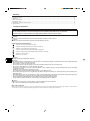
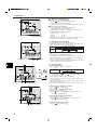
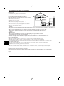
Air-Conditioners SEZ-A12, A18, A24AR OPERATION MANUAL FOR USER For safe and correct use, please read this operation manual thoroughly before operating the air-conditioner unit. BEDIENUNGSHANDBUCH FÜR BENUTZER Zum sicheren und einwandfreien Gebrauch der Klimaanlage dieses Bedienungshandbuch vor Inbetriebnahme gründlich durchlesen. MANUEL D’UTILISATION Italiano °π∞ ∆√¡ Ã∏™∆∏ °È· ·ÛÊ¿ÏÂÈ· Î·È ÛˆÛÙ‹ ¯Ú‹ÛË, ·Ú·Î·Ï›ÛÙ ‰È·‚¿ÛÂÙ ÚÔÛ¯ÙÈο ·˘Ùfi ÙÔ ÂÁ¯ÂÈÚ›‰ÈÔ ¯Ú‹Ûˆ˜ ÚÈÓ ı¤ÛÂÙ Û ÏÂÈÙÔ˘ÚÁ›· ÙË ÌÔÓ¿‰· ÎÏÈÌ·ÙÈÛÌÔ‡. MANUAL DE OPERAÇÃO PARA O UTILIZADOR Para segurança e utilização correctas, leia atentamente o manual de operação antes de pôr a funcionar a unidade de ar condicionado. DRIFTSMANUAL Español PER L’UTENTE Leggere attentamente questi istruzioni di funzionamento prima di avviare l’unità, per un uso corretto e sicuro della stessa. E°XEIPI¢IO O¢H°IøN XPH™Eø™ Nederlands PARA EL USUARIO Lea este manual de instrucciones hasta el final antes de poner en marcha la unidad de aire acondicionado para garantizar un uso seguro y correcto. ISTRUZIONI DI FUNZIONAMENTO Français VOOR DE GEBRUIKER Voor een veilig en juist gebruik moet u deze bedieningshandleiding grondig doorlezen voordat u de airconditioner gebruikt. MANUAL DE INSTRUCCIONES Deutsch POUR L’UTILISATEUR Pour une utilisation correcte sans risques, veuillez lire le manuel d’utilisation en entier avant de vous servir du climatiseur. BEDIENINGSHANDLEIDING English ∂ÏÏËÓÈο Português FÖR ANVÄNDAREN Läs denna driftsmanual noga för säkert och korrekt bruk innan luftkonditioneringen används. Svenska Contents 1. Safety Precautions ...................................................................................................................................................................... 2 2. Operation ..................................................................................................................................................................................... 3 3. Care and cleaning ....................................................................................................................................................................... 5 4. Troubleshooting ........................................................................................................................................................................... 5 5. Installation, relocation and inspection ......................................................................................................................................... 6 6. Specifications .............................................................................................................................................................................. 7 1. Safety Precautions s Before installing the unit, make sure you read all the “Safety precautions”. s The “Safety precautions” provide very important points regarding safety. Make sure you follow them. s Please report to or take consent by the supply authority before connection to the system. Symbols used in the text Warning: Describes precautions that should be observed to prevent danger of injury or death to the user. Caution: Describes precautions that should be observed to prevent damage to the unit. Symbols used in the illustrations : Indicates an action that must be avoided. : Indicates that important instructions must be followed. : Indicates a part which must be grounded. : Indicates that caution should be taken with rotating parts. : Indicates that the main switch must be turned off before servicing. : Beware of electric shock. : Beware of hot surface. Warning: Carefully read the labels affixed to the main unit. Warning: • The unit should not be installed by the user. Ask the dealer or an authorized company to install the unit. If the unit is installed improperly, water leakage, electric shock or fire may result. • Do not stand on, or place any items on the unit. • Do not splash water over the unit and do not touch the unit with wet hands. An electric shock may result. • Do not spray combustible gas close to the unit. Fire may result. • Do not place a gas heater or any other open-flame appliance where it will be exposed to the air discharged from the unit. Incomplete combustion may result. • Ventilate the room if refrigerant leaks during operation. If the refrigerant comes in contact with a flame, poisonous gases will be released. • Do not remove the front panel or the fan guard from the outdoor unit when it is running. You could be injured if you touch rotating, hot or high-voltage parts. • Never insert fingers, sticks etc. into the intakes or outlets, otherwise injury may result, since the fan inside the unit rotates at high speed. • If you detect odd smells, stop using the unit, turn off the power switch and consult your dealer. • This air conditioner is NOT intended for use by children or infirm persons without supervision. • Young children should be supervised to ensure that they do not play with the air conditioner. Caution: • Do not use any sharp object to push the buttons, as this may damage the remote controller. • Never block or cover the indoor or outdoor unit’s intakes or outlets. Disposing of the unit When you need to dispose of the unit, consult your dealer. If pipes are removed incorrectly, refrigerant (fluorocarbon gas) may blow out and come into contact with your skin, causing injury. Releasing refrigerant into the atmosphere also damages the environment. 2 2. Operation 2.1. Description of “AUTO RESTART FUNCTION” • This unit is equipped with the auto restart function. When the main power is turned on, the air conditioner will start operation automatically in the same mode as set with the remote controller before the shutoff of main power. • If the unit was set to off with the remote controller before the shutoff of main power, it will remain stopped even after the main power is turned on. • If the unit was in the TEST RUN before the shutoff of main power, it will start operation, at main power on, in the same mode as set with the remote controller before the TEST RUN. 2.2. Switching the unit on/off ˚C ˚C TEMP. ON/OFF A 1 FILTER CHECK TEST TIMER SET • The power supply should not be turned off while the air conditioner is in use. This can cause the unit to break down. 1 Press the ON/OFF button. AThe ON indicator should light up. • Even if you press the ON/OFF button immediately after shutting down the operation in progress, the air conditioner will not start for about three minutes. This is to prevent the internal components from being damaged. • If the operation stops due to a power failure, the unit will not automatically restart until the power has been restored. Press the ON/OFF button to restart. 2.3. Mode select B ˚C ˚C TEMP. ON/OFF A 1 FILTER 2 CHECK TEST TIMER SET 1 If the unit is off, press the ON/OFF button to turn it on. AThe ON indicator should light up. 2 Press the operation mode ( ) button and select the operation mode. B s Cooling mode Fan mode Heating mode Drying mode Automatic (cooling/heating) mode Information for multi system air conditioner (Outdoor unit: MXZ series) s Multi system air conditioner (Outdoor unit: MXZ series) can connect two or more indoor units with one outdoor unit. According to the capacity, two or more units can operate simultaneously. • When you try to operate two or more indoor units with one outdoor unit simultaneously, one for the cooling and the other for heating, the operation mode of the indoor unit that operates earlier is selected. The other indoor units that will start the operation later cannot operate, indicating an operation state. In this case, please set all the indoor units to the same operation mode. • There might be a case that the indoor unit, which is operating in (AUTO) mode. Cannot change over to the operating mode (COOL ↔ HEAT) and becomes a state of standby. • When indoor unit starts the operation while the defrosting of outdoor unit is being done, it takes a few minutes (max. about 15 minutes) to blow out the warm air. • In the heating operation, though indoor unit that does not operate may get warm or the sound of refrigerant flowing may be heard, they are not malfunction. The reason is that the refrigerant continuously flows into it. 3 2. Operation 2.4. Selecting a temperature A ˚C ˚C TEMP. TEMP. s To decrease the room temperature: button to set the desired temperature. 1 Press AThe selected temperature is displayed. • Each time you press the button, the temperature value decreases by 1 °C. s To increase the room temperature: 1 Press button to set the desired temperature. AThe selected temperature is displayed. • Each time you press the button, the temperature value increases by 1 °C. ON/OFF 1 FILTER CHECK TEST TIMER SET • Available temperature ranges are as follows: Cooling & Drying: 19 - 30 °C Heating: 17 - 28 °C Automatic: 19 - 28 °C • The display flashes either 8 °C - 39 °C to inform you if the room temperature is lower or higher than the displayed temperature. A 2.5. Selecting a fan speed 1 Press button to select a desired fan speed. • Each time you press the button, available options change with the display A on the remote controller, as shown below. Remote controller display Low High Fan speed ˚C ˚C ▼ 2-stage ON/OFF ▼ TEMP. The display and the fan speed of the unit will differ in the following situations: • When STAND BY and DEFROST are displayed. • Just after the heating mode (while waiting to change to another mode). • When the temperature of the room is higher than the temperature setting of the unit operating in the heating mode. • In the dry operation, the indoor fan automatically turns to low-speed operation. Switching of fan speed is impossible. FILTER CHECK TEST TIMER SET 1 2.6. Using the timer BA 1) Set the current time 1 Press button to display the “CLOCK” B. ON OFF Remote controller display A ˚C CLOCK → ↑ ON CLOCK → OFF CLOCK → No Display ˚C TEMP. ON/OFF ON OFF FILTER CHECK TEST TIMER SET 2 1 2 Each time you press button, the time increases in increments of one minute. Each time you press button, the time decreases in increments of one minute. • Press and hold the button to rapidly change the time. • The time changes in increments of one minute → ten minutes → in units of hour; in this order. • Approximately ten seconds after pressing the button, the display on the remote controller will turn off. The example shows a timer set for operation start at 8:00 and end at 17:00. 2) Set the mode to continuous as follows A BC button to display D 1 Press D . 3) Set the time to start the unit as follows 2 Press button to display B . 3 Press button to set the time that you want the unit to start. The start time is displayed at A. ON ON OFF ˚C TIMER SET ˚C TEMP. ON/OFF 4) Set the time to stop the unit as follows OFF FILTER CHECK TEST 1 TIMER SET 2 Press button to display C . 3 Press button to set the time that you want the unit to stop. The stop time is displayed at A. TIMER SET 5) Set the mode to timer as follows 1 Press 3 4 2 button to display D . 3. Care and cleaning 3.1. Cleaning the filters and the indoor unit Cleaning the filters • Clean the filters using a vacuum cleaner. If you do not have a vacuum cleaner, tap the filters against a solid object to knock off dirt and dust. • If the filters are especially dirty, wash them in lukewarm water. Take care to rinse off any detergent thoroughly and allow the filters to dry completely before putting them back into the unit. A Caution: • Do not dry the filters in direct sunlight or by using a heat source, such as an electric heater: this may warp them. • Do not wash the filters in hot water (above 50°C), as this may warp them. • Make sure that the air filters are always installed. Operating the unit without air filters can cause malfunction. Caution: • Before you start cleaning, stop operation and turn OFF the power supply. • The air filter should be obtained locally. Be sure to check on the location and the way of setting with the contractor when the unit perform a trial run. (Example) The air filter should be attached to the indoor unit’s air intake (rear side of unit). AAir intake BFilter B 4. Troubleshooting Before you call out a repair man, check the following table to see whether there is a simple solution to your problem. [for wired remote controller] Problem Unit does not cool or heat very well. The unit stops operating before arriving at the set temperature in the heating mode. A white mist is expelled from the indoor unit. The indicators of the remote controller do not light up when operated. The start and stop functions are not available just after restarting the unit. Solution Clean the filter. Frost forms when the outdoor temperature is low and humidity is high. Wait for about 10 minutes for the frost to melt. This may occur just after the unit is turned on when a high level of humidity is present in the room. Turn on the power switch. “ ” will be displayed. Wait about three minutes (operation has stopped to prevent damage to the air conditioner). Problem Solution “H0” is displayed in the remote con- An automatic startup test is being troller. performed (will last for about two minutes). An error code is displayed in the re- A self-diagnostic function is being mote controller. performed to preserve the air condiThe operating display of the wireless tioner. remote controller’s receiver is flash- * Do not attempt to make repairs ing. yourself. Turn the main switch off and contact the dealer from whom you bought the air conditioner. Provide him or her with the name of the unit and the information displayed in the remote controller. If none of the above apply, turn the main switch off and contact the dealer from whom you bought the air-conditioner, telling him the model name and the nature of the problem. Do not try to fix the unit yourself. In any of the following cases, turn off the main power switch and contact your local dealer for service: • The operation lamp (in the remote controller) flashes. • The switches do not work properly. • The circuit breaker trips frequently (or the fuse blows frequently). • Water has accidentally been splashed into the unit. • Water leaks from the unit. • Something is accidentally dropped into the air-conditioner. • An unusual noise is heard during operation. The following do not indicate any malfunction: Odours: smells such as tobacco or cosmetic odours may persist after they have been sucked into the unit. Sound of liquid flowing inside indoor unit: this can occur during or after operation and is simply the sound of refrigerant being circulated inside the unit. Ticking sound coming from indoor unit: this can occur when cooling or heating has just begun or has just stopped. It is caused by the indoor unit shrinking or expanding slightly due to the change in temperature. NOTE: The refrigerant charged in the air conditioner is safe. Refrigerant normally does not leak, however, if refrigerant gas leaks indoors, and comes into contact with the fire of a fan heater, space heater, stove, etc., harmful substances will be generated. Be sure to ask the service representative whether there is refrigerant leakage or not when repairs are carried out. 5 5. Installation, relocation and inspection Installation place Avoid installing the air conditioner in the following places. • Where flammable gas could leak. Caution: Do not install the unit where flammable gas could leak. If gas leaks and collects around the unit, it may cause an explosion. • • • • Where there is much machine oil. Salty place such as the seaside. Where sulfide gas is generated such as a hot spring. Where there is oil splashing or much oily smoke. Inverter type fluorescent lamp Wall, etc. To prevent the effect of a fluorescent lamp, keep it away as far apart as possible. To prevent picture distortion or noise, keep 1 m or more apart. Wellventilated dry place 100 mm or more 400 mm or more TV Electrical work • Provide an exclusive circuit for power supply of the air conditioner. • Be sure to observe the breaker capacity. Radio Warning: • The customer should not install this unit. If the unit is installed incorrectly, fire, electric shock, injury due to a falling unit, water leakage, etc. may result. • Do not connect using branched outlet or an extension cord, and do not attach many loads to one electric outlet. A fire or electric shock may result from poor contact, poor insulation, exceeding the permissible current, etc. Consult your dealer. Caution: • Apply grounding Do not connect a grounding wire to a gas pipe, water pipe, lightning rod or ground wire of a telephone. If a grounding is incorrect, it may cause an electric shock. • Install an earth leakage breaker depending on the place where the air conditioner is to be installed (humid place, etc.). If the earth leakage breaker is not installed, it may cause an electric shock. Inspection and maintenance • When the air conditioner is used for several seasons, the capacity may be lowered due to dirt inside the unit. • Depending upon the conditions of use, an odor may be generated or dirt, dust, etc. may prevent proper drainage. • It is recommended to apply inspection and maintenance (charged) by a specialist in addition to normal maintenance. Consult your dealer. Also consider operation sound • Do not put an object around the air outlet of the outdoor unit. It may cause lowering of capacity or increase operating sound. • If abnormal sound is heard during operation, consult your dealer. Relocation • When the air conditioner is to be removed or reinstalled because of rebuilding, moving, etc., special techniques and work are required. Warning: Repair or relocation should not be done by the customer. If this is done incorrectly, it may cause a fire, electric shock, injury by dropping of the unit, water leakage, etc. Consult your dealer. Disposal • To dispose of this product, consult your dealer. If you have any question, consult your dealer. 6 6. Specifications Model SEZ-A12AR Cooling Heating Function Power supply W BTU/h kW A Capacity Input Current Indoor unit Fan Airflow (Lo-Hi) CMM Ext. static Pa (mmAq) pressure Noise level (Lo-Hi) dB (A) kg Weight Outdoor unit Noise level (Lo-Hi) Refrigerant R410A Weight dB (A) kg kg SEZ-A24AR Cooling Heating 3400 3900 11600 13300 1.09 1.10 5.0 4.9 SEZ-A12AR 10-13 SEZ-A18AR Cooling Heating ~/N, 220-240V, 50Hz 4700 5700 16000 19400 1.67 1.78 7.4 7.9 SEZ-A18AR 12-17 30 (3) 30 (3) 30 (3) 30-35 33.5 SUZ-A12VR 48 0.90 34 31-39 33.5 SUZ-A18VR 55 1.8 72 32-43 33.5 SUZ-A24VR 55 2.4 72 Notes: 1. Rating conditions (cooling) Indoor : 27°C DB, 19°C WB 2. Rating conditions (heating) Indoor : 20°C DB 3. Specifications subject to change without notice. 5400 6500 18400 22100 1.92 2.02 8.5 9.0 SEZ-A24AR 12-20 Outdoor : 35°C DB Outdoor : 7°C DB, 6°C WB Guaranteed operating range Cooling Heating Upper limit Lower limit Upper limit Lower limit Indoor 32°C DB, 23°C WB 21°C DB, 15°C WB 27°C DB, – 20°C DB, – Outdoor 46°C DB, – -10°C DB, – 24°C DB, 18°C WB -10°C DB, -11°C WB Units should be installed by licensed electric contractor accordingly to local code requirement. 7 This product is designed and intended for use in the residential, commercial and light-industrial environment. The product at hand is based on the following EU regulations: • • Low Voltage Directive 73/23/ EEC Electromagnetic Compatibility Directive 89/ 336/ EEC Please be sure to put the contact address/telephone number on this manual before handing it to the customer. HEAD OFFICE: MITSUBISHI DENKI BLDG., 2-2-3, MARUNOUCHI, CHIYODA-KU, TOKYO 100-8310, JAPAN BG79S992H01 Printed in Thailand