1
INSTRUCTION MANUAL
DCP100
Data Collection Platform
2/99
C o p y r i g h t ( c ) 1 9 9 9
C a m p b e l l S c i e n t i f i c , I n c .
Warranty and Assistance
The DCP100 DATA COLLECTION PLATFORM is warranted by
CAMPBELL SCIENTIFIC, INC. to be free from defects in materials and
workmanship under normal use and service for twelve (12) months from date of
shipment unless specified otherwise. Batteries have no warranty. CAMPBELL
SCIENTIFIC, INC.'s obligation under this warranty is limited to repairing or
replacing (at CAMPBELL SCIENTIFIC, INC.'s option) defective products.
The customer shall assume all costs of removing, reinstalling, and shipping
defective products to CAMPBELL SCIENTIFIC, INC. CAMPBELL
SCIENTIFIC, INC. will return such products by surface carrier prepaid. This
warranty shall not apply to any CAMPBELL SCIENTIFIC, INC. products
which have been subjected to modification, misuse, neglect, accidents of
nature, or shipping damage. This warranty is in lieu of all other warranties,
expressed or implied, including warranties of merchantability or fitness for a
particular purpose. CAMPBELL SCIENTIFIC, INC. is not liable for special,
indirect, incidental, or consequential damages.
Products may not be returned without prior authorization. The following
contact information is for US and International customers residing in countries
served by Campbell Scientific, Inc. directly. Affiliate companies handle repairs
for customers within their territories. Please visit www.campbellsci.com to
determine which Campbell Scientific company serves your country. To obtain
a Returned Materials Authorization (RMA), contact CAMPBELL
SCIENTIFIC, INC., phone (435) 753-2342. After an applications engineer
determines the nature of the problem, an RMA number will be issued. Please
write this number clearly on the outside of the shipping container.
CAMPBELL SCIENTIFIC's shipping address is:
CAMPBELL SCIENTIFIC, INC.
RMA#_____
815 West 1800 North
Logan, Utah 84321-1784
CAMPBELL SCIENTIFIC, INC. does not accept collect calls.
WARNINGS FOR DCP100 USERS
1. The datalogger operating system must be compatible for use with the TGT-1. CR10X dataloggers
must have version 1.6 or later. All CR510 datalogger operating systems are compatible with the
DCP100. CR500 dataloggers need version 1.4 or later. CR23X dataloggers should have version
1.4 or later. CR10 and 21X dataloggers require a special PROM. CR10 PROM is item number
8131-00, 21X PROM is item number 8132-04. Check *B mode for operating system version. If you
did not purchase the TGT-1 and datalogger together, make sure you have the latest operating
system. Contact a Campbell Scientific Applications Engineer if you have any questions.
2. The datalogger clock must be set to Coordinated Universal Time. All references to time are based
on Coordinated Universal Time.
3. If you are using the keypad (CR10KD) when the datalogger initiates a P120 or P123 instruction, the
instruction will fail without reporting a failure.
4. Due to atmospheric interference and other sources of error, it is possible for a data transmission to
be missed by the ground station. If this happens, your missed data is still in the datalogger until
overwritten by new data.
5. The antenna must be connected before transmission or the transmitter will be damaged.
DCP100 DATA COLLECTION PLATFORM OPERATOR’S MANUAL
TABLE OF CONTENTS
PDF viewers note: These page numbers refer to the printed version of this document. Use
the Adobe Acrobat® bookmarks tab for links to specific sections.
PAGE
1.
INTRODUCTION.........................................................................................................................1
2.
GOES SYSTEM ..........................................................................................................................1
2.1
2.2
2.3
Orbit ...........................................................................................................................................1
NESDIS and TransmitWindows .............................................................................................1
Data Retrieval.............................................................................................................................1
3.
TGT1 TRANSMITTER SPECIFICATIONS .........................................................................2
4.
REQUIRED EQUIPMENT ........................................................................................................2
4.1
4.2
5.
5.1
5.2
5.3
6.
6.1
6.2
6.3
Computer Base Station ..............................................................................................................2
Field Station ...............................................................................................................................2
POWER SUPPLIES...................................................................................................................4
12 and 24 AHr Sealed Rechargeable Batteries .........................................................................4
AC Power and Deep-Cycle Rechargeable Batteries..................................................................4
Datalogger’s Batteries ................................................................................................................4
INSTALLATION ..........................................................................................................................4
Wiring .........................................................................................................................................4
Battery ........................................................................................................................................4
Antenna ......................................................................................................................................4
7.
FORWARD AND REFLECTED POWER ............................................................................7
8.
PROGRAMMING THE TRANSMITTER ..............................................................................8
8.1
8.2
8.3
8.4
9.
9.1
9.2
9.3
Star Pound Mode .......................................................................................................................8
Establishing and Editing Parameters .........................................................................................8
Status Information and Test Transmissions ..............................................................................9
Error Messages..........................................................................................................................9
PROGRAMMING THE DATALOGGER ............................................................................10
CR10X, CR10, CR510, and CR500 .........................................................................................10
Program Instruction 123 - TGT-1 Auto Setup ..........................................................................12
21X ...........................................................................................................................................14
I
TABLE OF CONTENTS
APPENDICES
A.
INFORMATION ON ELIGIBILITY AND GETTING ONTO THE
GOES SYSTEM................................................................................................................ A-1
A.1
A.2
Eligibility.................................................................................................................................. A-1
Acquiring Permission ............................................................................................................. A-1
B.
DATA CONVERSION COMPUTER PROGRAM .......................................................... B-1
C.
ANTENNA ORIENTATION COMPUTER PROGRAM ................................................C-1
D.
DETAILED FORWARD/REFLECTED POWER INFORMATION ............................D-1
D.1
D.2
D.3
Impedance Matching..............................................................................................................D-1
Calculating Power-Out ...........................................................................................................D-1
Impedance Match Datalogger Program .................................................................................D-1
E.
CHANNEL/FREQUENCY CORRELATION ................................................................... E-1
F.
DATA DUMP DATALOGGER PROGRAM .................................................................... F-1
F.1
F.2
F.3
F.4
F.5
F.6
F.7
Introduction............................................................................................................................. F-1
Toggling User Flag 1 High ..................................................................................................... F-1
Checking the Buffer................................................................................................................ F-1
Test Transmission.................................................................................................................. F-1
Toggling User Flag 2 High ..................................................................................................... F-1
CR10X Data Dump Program ................................................................................................. F-1
21X Data Dump Program....................................................................................................... F-2
G.
LOCAL MAGNETIC DECLINATION ................................................................................G-1
G.1
G.2
H.
H.1
H.2
H.3
I.
Determining True North..........................................................................................................G-1
Prompts from GEOMAG ........................................................................................................G-1
CHANGING THE CR10’S RAM OR PROM CHIPS ....................................................H-1
Disassembling the CR10........................................................................................................H-1
Installing New RAM Chips in CR10s with 16K RAM ..............................................................H-1
Installing New PROM .............................................................................................................H-1
21X PROM REPLACEMENT PROCEDURE .................................................................. I-1
I.1
I.2
Tools Required........................................................................................................................ I-1
Procedure................................................................................................................................ I-1
J.
TELONICS MODEL TGT1 GOES CERTIFICATION BY NOAA/NESDIA.............J-1
FIGURES
2-1
4-1
4-2
6.3-1
6.3-2
II
Data Retrieval Diagram ..............................................................................................................2
A Field Station Monitoring a Well’s Depth..................................................................................3
Inside the Enclosure of a Typical Field Station ..........................................................................3
Antenna Mounting Hardware, Exploded View............................................................................5
Antenna Mounting Hardware, Assembled View 1 ......................................................................6
TABLE OF CONTENTS
6.3-3
6.3-4
G-1
G-2
G-3
H-1
H-2
I-1
I-2
I-3
I-4
I-5
I-6
Antenna Mounting Hardware, Assembled View 2......................................................................6
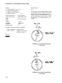
Example Antenna Orientation Diagram......................................................................................7
Magnetic Declination for the Contiguous United States.........................................................G-1
Declination Angles East of True North ...................................................................................G-2
Declination Angles West of True North..................................................................................G-2
Disassembling CR10.............................................................................................................. H-2
Jumper Settings for Different RAM Configurations ................................................................ H-2
Removing Faceplate Screws ...................................................................................................I-1
Separating the Faceplate from the Base..................................................................................I-1
Removing the Back Cover of the Faceplate ............................................................................I-2
Inside the Faceplate.................................................................................................................I-2
Removing the PROM with a Screwdriver .................................................................................I-2
Inserting the New PROM .........................................................................................................I-3
TABLES
6.1-1
8.2-1
8.2-2
8.3-1
9.1-1
9.1-2
9.2-1
9.3-1
9.3-2
D.1-1
D.2-1
Wiring Diagram ..........................................................................................................................5
*# Parameter’s Descriptions.......................................................................................................8
Decimal Equivalent ....................................................................................................................9
*#60 Commands ........................................................................................................................9
CR10X, CR10, CR510 and CR500’s Instruction Parameters ..................................................10
CR10X Example Program........................................................................................................11
P123 Parameter’s Descriptions................................................................................................13
21X’s Instruction 99 Parameters ..............................................................................................14
21X Example Program .............................................................................................................14
Impedance Matching Correlation ........................................................................................... D-1
Pout Values.............................................................................................................................. D-1
III
TABLE OF CONTENTS
This is a blank page.
IV
DCP100 DATA COLLECTION PLATFORM
OPERATOR'S MANUAL
1. INTRODUCTION
The DCP100 combines the measurement and
control capabilities of Campbell Scientific’s
dataloggers with the broad geographic
coverage afforded by GOES (Geogstationary
Operational Environmental Satellite) telemetry.
Satellite telemetry offers a convenient
telecommunication alternative for field stations
where phone lines or RF systems are
impractical.
The DCP100 contains the following
components:
•
Datalogger: Campbell’s CR23X, CR10X,
CR510, CR500, CR10, or 21X with
appropriate PROMs. A CR10KD
keyboard/display is required when using a
CR10X, CR10, or CR500.
•
Transmitter: TGT1 satellite transmitter and
power cable.
•
Antenna: Yagi antenna, mounting bracket
and coaxial cable.
•
Enclosure: Campbell's 16” by 18” fiberglass
enclosure with a water-tight compression
fitting for the antenna, 6 water-tight
compression fittings for the sensors and the
solar panel.
•
Power Supply: Typically a 12 AHr or 24 AHr
sealed rechargeable battery, a charging
regulator, and a solar panel.
The TGT1 transmitter supports one-way
communication, via satellite, from a Campbell
Scientific datalogger to a ground receiving
station. This transmitter features a crystal
oscillator that is digitally temperaturecompensated to prevent the frequency from
drifting into adjacent channels. The TGT1 is
manufactured for CSI by Telonics Inc. and interfaces directly to the datalogger's 9-pin I/O port.
2. GOES SYSTEM
2.1 ORBIT
The TGT1 transmitter sends data via
Geostationary Operational Environmental
Satellites (GOES). GOES satellites have orbits
that coincide with the Earth's rotation, allowing
each satellite to remain above a specific region.
This allows a user to point the GOES antenna
at a fixed position in the sky.
There are two satellites, GOES East and GOES
West. GOES East is located at 75° West
longitude and GOES West is located 135° West
longitude. Both satellites are located over the
equator. Within the United States, odd
numbered channels are assigned to GOES
East. Only even numbered channels are
assigned to GOES West. Channels used
outside the United States are assigned to either
spacecraft.
2.2 NESDIS AND TRANSMIT−WINDOWS
GOES is managed by the National
Environmental Satellite Data Information
Service (NESDIS). NESDIS assigns
addresses, uplink channels, and selftimed/random transmit time windows. Selftimed windows allow data transmission only
during a predetermined time frame (typically 1
minute every 3 or 4 hours). The self-timed data
is erased from the transmitter's buffer after
each transmission. Random windows are for
critical applications (e.g., flood reporting) and
allow transmission immediately after a
threshold has been exceeded. The
transmission is then randomly repeated to
ensure it is received. A combination of selftimed and random windows can be executed by
the TGT-1.
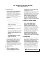
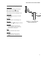
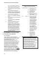
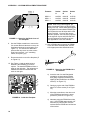
2.3 DATA RETRIEVAL
Data retrieval via the TGT1 and the GOES
system is illustrated in Figure 2-1. The User
Interface Manual, provided by NOAA/ NESDIS,
describes the process of retrieving the data
from the NESDIS ground station. The data are
in the form of 3-byte ASCII (see Appendix B for
a computer program that converts the data to
decimal). You can also retrieve data directly
from the NESDIS ground station via the
DOMSAT satellite downlink. DOMSAT is only
practical for organizations with many GOES
users; contact NESDIS for more information
(see Appendix A).
NOTE: Array IDs less than 255 are not
transmitted.
1
DCP100 DATA COLLECTION PLATFORM
NESDIS
Wallops Station, VA
ground station has
10 asynchronous
dial-up circuits
Computer Base Station
DCP100
Data Collection Platform
Yagi antenna
Environmental enclosure
Phone
modem
Phone
line
NESDIS
Wallops Station, VA
ground station has
10 asynchronous
dial circuits
communication/power cable
Antenna cable
Transmitter
Datalogger
Power
supply
FIGURE 2-1. Data Retrieval Diagram
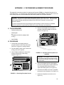
3. TGT1 TRANSMITTER
SPECIFICATIONS
•
Phone modem with MNP level 4 error
correction. (Most commercially available
Hayes-compatible modems contain this
error-checking protocol. Check the
operator's manual for your modem).
•
Computer with user-supplied communication software (e.g., Procomm Plus,
Crosstalk).
Output level: +40 dBm (10 watts), +1.0 dBm
at 12 VDC with automatic leveling control
Typical current drain: 9 mA quiescent, 2200
mA active
Operating temperature range: −40° to +60°C
Supply voltage range: 10.5 to 14.0 VDC
Dimensions: 3.5" x 7.2" x 4.4" (8.9 x 18.3 x
11.2 cm)
Weight: 2.1 lbs (1.0 kg)
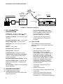
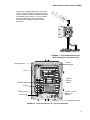
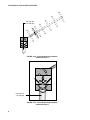
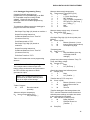
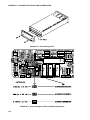
4.2 FIELD STATION
The field stations equipment is illustrated in
Figures 4-1 and 4-2. The required equipment is
listed below.
Self-timed buffer: 2000 bytes
•
TGT1 satellite transmitter.
Random buffer: 2000 bytes
•
Datalogger (CR23X, CR10X, CR500,
CR510, CR10, or 21X). A CR10KD
keyboard/display is required when using a
CR10X, CR10, CR510, or CR500. The
CR10 and 21X require a special PROM.
When using a 21X with both a TGT1 and a
storage module (SM192, SM716, or CSM1),
hardware and datalogger programming
modifications are required. Contact a
Campbell Scientific applications engineer
for more information.
•
Yagi antenna, mounting bracket, and
coaxial cable.
•
Weather-proof enclosure.
•
12 Volt power supply, charging regulator, and
a solar panel.
•
A filter is also required when measuring
sensor(s) requiring equalization with the
atmosphere (e.g., vented pressure transducers,
Transmission rate: 100 bits per second
Typical number of data points transmitted:
118 for a 1 minute transmit-window (with 15
second guard bands)
Maximum EIRP allowed by NESDIS: +50 dB
Antenna's maximum gain: +9 dB with righthand circular polarization, +12 dB with linear
polarization.
Clock accuracy: Capable of running 420 days
without adjustment.
4. REQUIRED EQUIPMENT
4.1 COMPUTER BASE STATION
The equipment required at the computer base
station is listed below.
2
ASLFJO AKD
ASLFJO AKD
ASLFJO AKD
ASLFJO AKD
UNITED
tryu to read this whoever
ASLFJO AKD
ASLFJO AKD
ASLFJO AKDASLFJO AKD ASLFJO AKD
ASLFJO AKD
AKD AKD
ASLFJO AKDASLFJO AKD ASLFJO ASLFJO
ASLFJO AKDASLFJO AKD ASLFJO AKD
ASLFJO AKD
ASLFJO AKD ASLFJO AKD
ASLFJO AKD
ASLFJO AKD
ASLFJO AKD ASLFJO AKD
ASLFJO AKD
ASLFJO AKD
ASLFJO AKD ASLFJO AKD
ASLFJO AKD
ASLFJO AKD
BATT
DESI PAK.
DESI PAK.
SPECIFICATION MIL-D-3463
SPECIFICATION MIL-D-3463
DO NOT EATDO NOT EAT
ON
ON
OFF
BATT
SERIAL I/O
G 12V
POWER
IN
12V 12V
G G G G
thia thia
thia thia
thia thia
thia thia
thia thia
thia thia
thia thia
thia thia
tryu to read this whoever
EARTH
KALDHFI;O
KALDHFI;O AKJI AI AJHFHO
AKJI AI AJHFHO ALDLIFJ
ALDLIFJ
DO NOT EATDO NOT EAT
DES DES
I PAK I PAK
.
.
DESI PAK.
DESI PAK.
SPECIFICATION MIL-D-3463
SPECIFICATION MIL-D-3463
DO NOT EATDO NOT EAT
AKD AKD
ASLFJO AKDASLFJO AKD ASLFJO ASLFJO
AKD AKD
ASLFJO AKDASLFJO AKD ASLFJO ASLFJO
AKD AKD
ASLFJO AKDASLFJO AKD ASLFJO ASLFJO
ASLFJO AKD
ASLFJO AKD
ASLFJO AKD
KALDHFI;O AKJI AI AJHFHO
KALDHFI;O
AKJI AI AJHFHO ALDLIFJ
ALDLIFJ
ASLFJO AKD
ASLFJO AKD
ASLFJO AKD
UNITED DESICCANTS
UNITED DESICCANTS
-GATES
-GATES
UNITED DESICCANTS
UNITED DESICCANTS
-GATES
-GATES
DESI PAK
DESI PAK
.
.
ASLFJO AKD
ASLFJO AKD
UNIT
DESICCA ED DESICCA
NTS
NTS-GAT
UNITE-GATES
ES
D DES
ICC
ICC
D DES
ANTS-G
DE ANTDS-G
ATES
SI EATE
SS
PA I PA
K.
K.
UNITE
DO NOT EATDO NOT EAT
ASLFJO AKD
ASLFJO AKD ASLFJO AKD
ASLFJO AKD
ASLFJO AKD
ASLFJO AKD ASLFJO AKD
ASLFJO AKD
ASLFJO AKD
ASLFJO AKD ASLFJO AKD
ASLFJO AKD
ASLFJO AKD
SPECIFICATION MIL-D-3463
SPECIFICATION MIL-D-3463
KALDHFI;O AKJI AI KALDHFI;O AKJI AI
AJHFHO ALDLIFJ AJHFHO ALDLIFJ
ASLFJO AKD
ASLFJO AKD
ASLFJO AKD
UNITED
Compression Fittings
Desiccant
ASLFJO AKD
Antenna Cable
DESI PAK.
DESI PAK.
SC925G Cable
ASLFJO AKD
thia thia
thia thia
ASLFJO AKD
DESICCANTS-GDESICCANTS-G
ATES
UNITED
UNITED ATES
DESICCAN DESICCAN
TS-GATES TS-GATES
thia thia
thia thia
ASLFJO AKD
thia thia
ASLFJO AKD
thia thia
thia thia
thia thia
thia thia
thia thia
thia thia
Optional
Storage
Module
thia thia
UNITED DESICCANTS-GATES
UNITED DESICCANTS-GATES
UNITED DESICCANTS-GATES
UNITED DESICCANTS-GATES
thia thia
thia thia
UNITED
SERIAL I/O
G 12V
POWER
IN
12V 12V
G G G G
12 AHr or 24 AHr
Battery and
Bracket
Ground Lug
INT
CH12R
1
2
3
AG H L AG H L AG H L AG E1 E2 G G
DIFF
CR10
CAMPBELL
SCIENTIFIC
INC.
MADE IN USA
WIRING PANEL NO.
SWITCHED
12V
CONTROL
G 5V 5V P1 P2
C8 C7 C6 C5 C4 C3 C2 C1
EARTH
6
5
4
3
2
SWITCHED
12V
SE
AG H L AG H L AG H L AG E3 AG G G
4
5
6
7 8
9 10
11 12
DIFF
1
SE
ASLFJO AKD
CR10X
Datalogger
16/18 Enclosure
CR10
CAMPBELL
SCIENTIFIC
INC.
MADE IN USA
WIRING PANEL NO.
SWITCHED
12V
CONTROL
G 5V 5V P1 P2
C8 C7 C6 C5 C4 C3 C2 C1
DIFF
1 2
3 4
5 6
1
2
3
AG H L AG H L AG H L AG E1 E2 G G
SE
SWITCHED
12V
SE
AG H L AG H L AG H L AG E3 AG G G
4
5
6
7 8
9 10
11 12
DIFF
SPECIFICATION MIL-D-3463
SPECIFICATION MIL-D-3463
KALDHFI;O AKJI AI AJHFHO
KALDHFI;O AKJI AI AJHFHO
ALDLIFJ
ALDLIFJ
OFF
DCP100 DATA COLLECTION PLATFORM
barometers). Campbell Scientific’s pn 6832 fits
into one of the enclosure’s compression fittings
to allow pressure equalization between the inside
and outside of the enclosure. The filter retards
the entry of water vapor into the enclosure
protecting the transmitter and measurement
electronics.
thia thia
thia thia
thia thia
thia thia
thia thia
thia thia
thia thia
thia ia thia ia
thia thia
CHG
CHG
EXT
+12
+12
INT
FIGURE 4-1. A Field Station Monitoring a
Well's Depth (Solar Panel Not Shown)
TGT1
thia thia
thia ia thia ia
thia thia
EXT
CHG
CHG
+12
+12
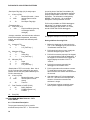
FIGURE 4-2. Inside the Enclosure of a Typical Field Station
3
DCP100 DATA COLLECTION PLATFORM
5. POWER SUPPLIES
5.1 12 AND 24 AHR SEALED RECHARGEABLE
BATTERIES
Typically, the system is powered with a 12 Volt,
12 AHr sealed rechargeable battery that
connects to a charging regulator and a solar
panel. The 12 AHr battery lasts 15 to 20 days
per charge. A 24 AHr sealed rechargeable
battery which lasts 30 to 40 days is available.
NOTE: This assumes the data are
transmitted for 30 seconds at 3 hour
intervals. The datalogger's scan rate is 1
second, and the sensors have negligible
power consumption.
A discharged 12 AHr battery is recharged by a
10 watt solar panel in 2 to 3 days when there
are a 1000 watts per square meter of
illumination and the solar panel temperature is
25°C. A 20 watt solar panel is available. The
minimum daily battery voltage should be
monitored with datalogger program Instruction
10, and output as a part of the user’s data
stream.
5.2 AC POWER AND DEEP-CYCLE
RECHARGEABLE BATTERIES
Although either the 12 or 24 AHr battery is
sufficient for most systems, applications with
high current drain sensors or peripherals (e.g.,
SDM devices) might require AC power or a
user-supplied deep-cycle rechargeable battery
that is trickle-charged with a 20 Watt solar
panel. Campbell Scientific's power supply
brochure and application note provide
information about determining your system's
power requirements.
5.3 DATALOGGER'S BATTERIES
The transmitter's power consumption is too high
for alkaline batteries. The 21XL's rechargeable
batteries do not source sufficient current for the
transmitter. Although the PS12LA 7 AHr battery
can power the transmitter, the battery only lasts
3 to 7 days per charge. One option is to have
the datalogger's batteries power the datalogger
and sensors, while the transmitter uses a 12
AHr battery, a 24 AHr battery, or a deep-cycle
battery.
4
NOTE: The datalogger's batteries should
be removed when not in use.
Rechargeable batteries should be trickle
charged with either Solar or AC power
through a charging regulator.
6. INSTALLATION
6.1 WIRING
The DCP100 hardware (excluding the battery
and solar panel) and the datalogger are
premounted and prewired. The enclosure's
ground lug must be connected to an
appropriate earth ground (see Table 6.1-1).
6.2 BATTERY
Before installing the battery, turn OFF the
charging regulator’s (CH12R) power switch. To
install the battery, remove the battery bracket
from the DCP100 and insert the battery facing
outward into the bracket. When inserting the 24
AHr battery into its bracket, the battery’s power
connections (posts) go on the top side where a
section of the bracket has been cut away.
Reattach the bracket to the DCP100’s
enclosure, and connect the battery cable (see
Table 6.1-1). The antenna must be connected
to the transmitter before turning on the
CH12R's power switch.
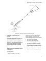
6.3 ANTENNA
You mount the antenna to a tripod, tower, or
vertical 1.5" OD pipe (see Figures 6.3-1 through
6.3-3). The antenna is then oriented towards
the satellite by using a computer program (see
Appendix C). This program prompts you for the
satellite's longitude (provided by NESDIS) and
the antenna's longitude, latitude, and height. It
then calculates the antenna's elevation and
azimuth (see Figure 6.3-4). You must also
account for local magnetic declination (see
Appendix G).
After the antenna is properly oriented, insert the
antenna cable into the enclosure's largest
compression fitting and connect the cable to the
transmitter.
CAUTION: The antenna must be connected
before transmission or the transmitter will be
damaged.
DCP100 DATA COLLECTION PLATFORM
TABLE 6.1-1 Wiring Diagram
SC925G Cable
25-Pin connector connects to TGT1 I/O port
Black connects to CH12R
(Ground)
Red connects to CH12R +12 Terminal
9-Pin connector connects to datalogger I/O port
Antenna Cable
BNC male connector connects to TGT1 BNC
female port
Red Cable
Connects to CH12R +12 and datalogger 12 V
Black Cable
Connects to CH12R
and datalogger G (Ground)
FIGURE 6.3-1. Antenna Mounting
Hardware, Exploded View
Green Cable
Connects to datalogger G (Ground) and is
routed through the enclosures ground lug
and connected to earth ground
Battery
Connects to CH12R INT white connector
GOESBKT2
(satellite)
Solar Panel
Black and white leads connect to the two
CH12R CHG Ports. Polarity does not
matter.
5
DCP100 DATA COLLECTION PLATFORM
Fits onto the
1.5" OD pipe
FIGURE 6.3-2. Antenna Mounting Hardware,
Assembled View 1
Fits onto the
1.5" OD pipe
FIGURE 6.3-3. Antenna Mounting Hardware,
Assembled View 2
6
DCP100 DATA COLLECTION PLATFORM
GOES SATELLITE
s)
ile
m
3
2,
(2
00
DATA
COLLECTION
PLATFORM
ANTENNA
36 (Elevation Angle)
S (180 )
213 (Azimuth Angle)
W
(270 )
E
(90 )
N
(360 )
EXAMPLE ORIENTATION
FIGURE 6.3-4. Example Antenna Orientation Diagram
7. FORWARD AND REFLECTED
POWER
Forward and reflected power are measured (in
decimal units) and updated during each
transmission (see Sections 8 and 9). The
forward power must be between 165 and 215
for the transmitter's output level to be within
specifications. The antenna/cable assembly is
operating properly when the percentage of
power reflected is less than 5. A reflected
power reading of 27 is 5% of 165 and 2.7% of
215.
This percentage can be estimated with the
following equation (see the datalogger program
in Appendix D.3).
When the percentage of power reflected is
greater or equal to 5, one or more of the
following situations exist and must be corrected:
•
The antenna is not connected.
•
The antenna is too close to metal.
•
You are transmitting inside a building.
•
The antenna is covered with snow or ice.
•
The frequency that the antenna is tuned to
does not match the transmitter's frequency.
•
There is a problem with the coaxial cable
connector or connection.
•
There is a problem with the antenna cable.
% power reflected =
2
[((ref + 17.4)/(fwd + 17.4)) x 100] - 1
7
DCP100 DATA COLLECTION PLATFORM
8. PROGRAMMING THE TRANSMITTER
8.1 STAR POUND MODE
The star/pound (*#) mode is for programming the
transmitter. It establishes and edits parameters,
displays status information, and performs test
transmissions. The *# mode can only be
accessed via a keyboard/display (not with a
computer).
TABLE 8.2-1. *# Parameter's Descriptions
Parameter Description
1-3
Set the transmitter's clock. All
scheduled operations are referenced to this clock. Because
timing is critical, it must be set to
Coordinated Universal Time (CUT).
CUT can be obtained by calling the
WWV or WWVH time services (call
(303) 499-7111 for WWV time and
(808) 335-4363 for WWVH). The
clock must be reset at least once a
year. Parameter 1 is hours; 2 is
minutes and 3 is seconds. The
TGT-1 clock is set and starts to run
when the “A” key is pressed after
rd
the 3 parameter. Note: This is a
24-hour format.
4 - 11
The NESDIS-assigned address.
Convert the letters in the address to
their decimal equivalent (Table 8.2-2).
For example when the address is
0104C186, parameters 4 through 11
are the following:
NOTE: *# mode cannot be accessed
without a P120 instruction in the program
table.
8.2 ESTABLISHING AND EDITING
PARAMETERS
The parameters set the transmitter's clock and
define the address, transmission intervals, and
uplink channels (see Table 8.2-1). The
parameters are temporarily stored in the
datalogger. The clock parameters are transferred
to the TGT-1 after parameter 3 is entered with the
“A” key. The remaining parameters are
transferred to the TGT-1 after parameter 26 is
entered with the “A” key. If the keyboard/display
sits idle for 2 minutes, the datalogger will discard
all changes that have not been transferred to the
TGT-1.
Parameter Number
04:
05:
06:
07:
08:
09:
10:
11:
Before establishing the parameters, type in *0.
The display should show only LOG, not LOG1,
LOG2, or LOG12.
CAUTION: The *# mode will not run when
*1 and *2 are active, therefore their scan
rates must be set to zero.
Enter the *# mode by typing in *#. The colon
disappears during the upload process and
reappears when the process is complete. 12:00
is displayed when you are in *# mode. Press A
to edit parameters. 01: is then displayed
indicating the datalogger is ready for parameter
1. You type an A to store each parameter and
to advance to the next one. Individual
parameters can also be edited by typing in *#
and the parameter number. Remember, the
TGT-1 clock is not changed until the “A” key is
rd
pressed after the 3 parameter. No other
changes are saved until the “A” key is pressed
th
after the 26 parameter.
8
User Types
0A
1A
0A
4A
12 A
1A
8A
6A
12
NESDIS-assigned self-timed uplink
channel (see Appendix E channel/
frequency correlation). If not assigned
a self-timed channel, type in zeros.
13
NESDIS-assigned random uplink
channel (see Appendix E for channel/
frequency correlation). If not assigned a
random channel, type in zeros.
14 - 17
Self-timed transmission interval is
NESDIS-assigned and usually 3 or 4
hours (minimum interval is 15 minutes).
Parameter 14 is days; 15 is hours; 16 is
minutes and 17 is seconds. Note: This
is a 24-hour format.
DCP100 DATA COLLECTION PLATFORM
18 - 20
Random transmission interval (the
NESDIS-assigned time period that
the transmission is randomly repeated, minimum interval is 5
minutes). Parameter 18 is hours; 19
is minutes and 20 is seconds.
21 - 23
Set the time of the initial self-timed
transmission (NESDIS-assigned).
The “initial” time is not the first time
but an offset. Self-timed
transmissions occur on multiples of
the self-timed transmission interval
plus the offset. Parameter 21 is
hours; 22 is minutes and 23 is
seconds. Note: This is a 24-hour
format.
24
Transmit window length is NESDISassigned and usually 1 minute.
Type 0 for a 1 minute window or 1
for a 2 minute window. The
transmission is automatically
centered around the middle of the
transmit window.
25
26
Sets the preamble length. In
general, type 0 to use a short
preamble (0.98 seconds) for
stationary land based stations.
Random mode requires the short
preamble. Type 4 for a long
preamble (7.3 seconds). A long
preamble increases the time the
satellite can lock onto the signal but
reduces the time for transmitting
data.
Selects the buffer or buffers used.
Type 1 to select only the self-timed
buffer, a 2 to select only the random,
and a 3 to select both buffers. These
buffers must match Instruction 120's
parameters (see Section 9).
TABLE 8.2-2 Decimal Equivalent
Number
or letter
1
2
3
4
5
6
7
8
9
A
B
C
D
E
F
Decimal
equivalent
1
2
3
4
5
6
7
8
9
10
11
12
13
14
15
8.3 STATUS INFORMATION AND TEST
TRANSMISSIONS
The *#60 mode is for displaying status information and performing test transmissions. *#60
mode is entered by typing *#60A. The
execution interval must be set to zero in table 1
and 2. You perform each command by typing
the command number (see Table 8.3-1) and an
A. Multiple parameter commands require
typing an A to advance to the next parameter.
8.4 ERROR MESSAGES
There are two error messages. The E101
message appears after the user types *# and
indicates the transmitter is not communicating
with the datalogger (i.e., TGT1 is not powered
or connected to datalogger). E102 appears
after a parameter is entered incorrectly.
TABLE 8.3-1 *#60 Commands
Command
Number Description
1
Displays the current TGT-1 time;
hours, minutes, and seconds are the
parameters. The TGT-1 time is
retrieved when the “A” key is pressed.
2
The amount of time until the next
transmission of the active buffer;
parameters are days, hours, minutes,
and seconds. If [31:31:63:63] is
displayed, the active buffer contains
no data. The time is retrieved when
9
DCP100 DATA COLLECTION PLATFORM
the “A” key is pressed. The active
buffer is set using command 7 and 8.
3
Forward power is the first parameter
and reflected power is the second (see
Section 7).
4
The first parameter displays the
number of errors. Parameters 2-9 list
the history of errors, where parameter
2 is the most recent (see Section 8.4).
5
Number of bytes in self-timed or
random buffer (used after command
6 or 7).
6
Selects self-timed buffer (used before
command 5).
7
Selects random buffer (used before
command 5).
8
Initiates test transmission of data in
the random buffer. You must be
assigned a random channel (see *#
parameter 13) or obtain from NESDIS
a channel for testing. The random
buffer must contain data. The TGT-1
will not perform a test transmission
more often then once each minute.
Clear the random buffer before final
TGT-1 setup. Appendix F contains a
datalogger program that dumps data
into the random buffer.
9. PROGRAMMING THE DATALOGGER
9.1 CR10X, CR10, CR510, AND CR500
9.1.1 Instruction
CR10X, CR500, and CR510 dataloggers
contain program Instruction 120 which transfers
the final storage data to the transmitter's buffer
and designates locations for the
forward/reflected power. The CR10s use
Instruction 99 instead of Instruction 120. The
CR10 Instruction 99 and CR10X Instruction 120
are identical except for the instruction number.
This instruction also automatically compares
the datalogger to the transmitter clock. If the
clocks differ more than 3 seconds, the
datalogger's clock is set to the transmitter's.
However, only the seconds are compared.
Therefore, the datalogger's clock is NOT reset
when the minutes or hours differ. The complete
time (HH:MM:SS) will be updated if the clocks
differ by more than 3 seconds. Table 9.1-1 lists
and describes Instruction 120's parameters.
10
TABLE 9.1-1 CR10X, CR10, CR510 and
CR500’s Instruction Parameters
01: ABC Where: A = 0 binary mode (3-bytes
per data point)
A = 1 ASCII mode (7-bytes
per data point)
B = 0 self-timed buffer
B = 1 random buffer
C = 0 appends the new data
to the old data
C = 1 writes over the old data
02: z
Where: z > 0 Starting input location
for the forward power
reading (see Section
7). The next input
location automatically
contains the reflected
power reading (e.g.,
when the forward
power's input location
is 10, the reflected
power's input location
is 11). By placing
these readings into
input locations, you can
sample and output the
forward and reflected
power as part of the
data stream
(Instruction 70).
z = 0 The forward and
reflected power
readings are NOT
placed into input
locations.
NOTE: The ASCII option (1xx) requires
approximately 7 bytes per data point which
is double the number of bytes required for
the binary option (0xx). This is a convenient
method of sending data since no postprocessing conversion is required.
However, the required transmission time for
ASCII is doubled. With a typical
transmission window of one-minute, you
can send up to 59 data points in ASCII or
118 data points in binary (this allows 15
second guard bands before and after
transmission to allow for normal clock drift).
DCP100 DATA COLLECTION PLATFORM
9.1.2 Datalogger Programming Theory
Campbell Scientific dataloggers are
programmed via a keyboard/display or an IBMPC compatible computer running PC208
software. Please see the appropriate
datalogger manual for detailed programming
information.
To transmit two different arrays the datalogger's
program must have this structure:
Set Output Flag 0 high (10) based on condition 1
Output Processing Instructions
Conditional Statement; if true “Then Do”
(Command Code 30)
P120 Data transfer to TGT1
Set Output Flag 0 high (10) based on
condition 2
Output Processing Instructions
Conditional Statement; if true “Then Do”
(Command Code 30)
P120 Data Transfer to TGT1
Table 9.1-2 illustrates the correct programming
structure.
TABLE 9.1-2 CR10X Example Program
This example makes a thermocouple and
battery voltage measurement and sends data to
the TGT1's buffer only when the CR10X
generates an output.
NOTE: Use a conditional statement (i.e.,
Instruction 92) to transfer data only when
there is an output to final storage.
;
*Table 1 Program
01:
10.0
Execution Interval
(seconds)
;Measure reference temperature.
01: Internal Temperature (P17)
1:
1
Loc [ RefTemp ]
;Measure thermocouple temperature.
02: Thermocouple Temp (DIFF) (P14)
1:
1
Reps
2:
1
± 2.5 mV Slow Range
3:
5
DIFF Channel
4:
1
Type T (Copper-Constantan)
5:
1
Ref Temp Loc [ RefTemp ]
6:
2
Loc [ TCDeg_C ]
7:
1
Mult
8:
0
Offset
;Measure battery voltage every 10 seconds.
03: Batt Voltage (P10)
1:
3
Loc [ Battery ]
;Set Output Flag High (10) for hourly data (user
defined).
04: If time is (P92)
1:
0
Minutes (Seconds --) into a
2:
60
Interval (same units as above)
3:
10
Set Output Flag High
;Timestamp data
05: Real Time (P77)
1:
220
Day,Hour/Minute (prev day
at midnight, 2400 at
midnight)
;Output hourly the average reference Temp, TC
Temp, and battery voltage.
06: Average (P71)
1:
3
Reps
2:
1
Loc [ RefTemp ]
;Sample the forward and reflected power.
07: Sample (P70)
1:
2
Reps
2:
4
Loc [ FwdPwr ]
;Transfer data to TGT1 every hour.
08: If time is (P92)
1:
0
Minutes (Seconds --) into a
2:
60
Interval (same units as
above)
3:
30
Then Do
;Transfer datalogger's final storage data to the
TGT1, read the transmitter's latest forward and
reflected power readings, and place the results
in two sequential input locations.
09: Data Transfer to GOES (P120)
1:
00
Buffer Selection
2:
4
FWD/Ref Power Loc
[ FwdPwr ]
10:
End (P95)
11
DCP100 DATA COLLECTION PLATFORM
;Set Output Flag High (10) for daily output.
11: If time is (P92)
1:
0
Minutes (Seconds --) into a
2: 1440
Interval (same units as
above)
3:
10
Set Output Flag High
;Timestamp data
12: Real Time (P77)
1:
220
Day,Hour/Minute (prev day
at midnight, 2400 at
midnight)
;Average, maximize, and minimize the reference
and thermocouple temperatures, the battery
voltage, and the forward and reflected power
readings.
13: Average (P71)
1:
5
Reps
2:
1
Loc [ RefTemp ]
14: Maximize (P73)
1:
5
Reps
2:
0
Value Only
3:
1
Loc [ RefTemp ]
15: Minimize (P74)
1:
5
Reps
2:
0
Value Only
3:
1
Loc [ RefTemp ]
;Sends data to TGT1 once a day. Note: this is
set for 5 minutes after midnight to give ample
transfer time for the hourly data initiated by the
P120 in instruction 09.
16: If time is (P92)
1:
5
Minutes (Seconds --) into a
2: 1440
Interval (same units as
above)
3:
30
Then Do
17: Data Transfer to GOES (P120)
1:
00
Buffer Selection
2:
4
FWD/Ref Power Loc [
FwdPwr ]
18:
End (P95)
9.2 PROGRAM INSTRUCTION 123 - TGT-1
AUTO SETUP
9.2.1 Functional Description
The program instruction P123 is used for
automatic setup of the TGT-1. This instruction
12
is used in place of the Star Pound Mode (*#).
P123 will transfer all the information needed to
properly transmit data via the TGT-1 satellite
transmitter. The information is assigned by
NESDIS. See table 9.2-1 for a complete
description of each parameter of P123.
P123 is only available on CR10X dataloggers
with version 1.6 operating system or later,
CR500 dataloggers with version 1.4 or later,
and all CR23X and CR510 dataloggers.
NOTE: P123 should only be run once.
See program example for one way to run P123.
Some guidelines for using P123:
1. Before the datalogger is connected to the
TGT-1, the datalogger clock must be set to
“Coordinated Universal Time”.
2. P123 should only be run once, usually the
first time through Program Table 1.
3. P123 will not execute properly if the keypad
is in communications with the datalogger. If
the keypad is connected to the logger, the
keypad display must show “LOG 1” or
“LOG12”.
4. P123 will not execute properly if the
datalogger is connected to a PC.
5. P123 requires about 8 seconds to execute.
To avoid table overrun errors, program
table execution rate should not be less then
10 seconds.
6. After the initiation of P123 the datalogger
and TGT-1 should not be interrupted for 1
minute or 2 times the execution rate,
whichever is longer.
7. The hardware must be completely setup
before power is applied to the system.
DCP100 DATA COLLECTION PLATFORM
TABLE 9.2-1. P123 Parameter Descriptions
Parameter
Number
Description
1-8
The NESDIS-assigned address.
Convert the letters in the address to
their decimal equivalent (Table 8.22). Each digit of the address is
placed in one parameter.
09
NESDIS-assigned self-timed uplink
channel (see Appendix E channel/
frequency correlation). If not assigned
a self-timed channel, type in zeros.
10
NESDIS-assigned random uplink
channel (see Appendix E for
channel/ frequency correlation). If
not assigned a random channel,
type in zeros.
11 - 14
Self-timed transmission interval is
NESDIS-assigned and usually 3 or 4
hours. Parameter 11 is days, 12 is
hours, 13 is minutes, and 14 is seconds.
Note: This is a 24-hour format.
15 - 17
Random transmission interval (the
NESDIS-assigned time period that
the transmission is randomly
repeated). Parameter 15 is hours,
16 is minutes, and 17 is seconds.
18 - 20
Set the time of the initial self-timed
transmission (NESDIS-assigned).
Parameter 18 is hours, 19 is
minutes, and 20 is seconds. Note:
This is a 24-hour format.
21
Transmit window length is NESDISassigned and usually 1 minute.
Type 0 for a 1 minute window or 1
for a 2 minute window.
22
Sets the preamble length. A long
preamble increases the time the
satellite can lock onto the signal but
reduces the time for transmitting
data. The random mode requires
the short preamble. For a long
preamble (7.3 seconds), type 4.
For a short preamble (0.98
seconds), type 0.
23
Selects the buffer or buffers used.
Type 1 to select only the self-timed
buffer, a 2 to select only the
random, and a 3 to select both
buffers. These buffers must match
Instruction P120 parameters (see
Section 9).
Program example using P123 instruction
This is not the only way to run P123. The
programming theory used in this example is as
follows. Using a P91 statement determine if
Flag x is low, if true set Flag x high and execute
P123. When the datalogger is powered up all
Flags are automatically set low. The datalogger
will detect that Flag 1 is low, set Flag 1 high,
and execute P123. If power is lost, P123 will
automatically be executed when power is
restored.
In this example the datalogger will configure the
TGT-1 transmitter to use the NESDIS assigned
address of “0104C186”, interval or self-timed
channel number 151, with a 1 minute window
every 4 hours. Preamble will be set to short.
The random channel is not used.
1:
1:
2:
If Flag/Port (P91)
21
Do if Flag 1 is Low
30
Then Do
2: Do (P86)
1:
11
Set Flag 1 High
3: Automatic Setup of TGT1 (P123)
1:
0
Address
2:
1
Address
3:
0
Address
4:
4
Address
5:
12
Address
6:
1
Address
7:
8
Address
8:
6
Address
9:
151
Assigned Uplink Channel
10:
0
Random Uplink Channel
11:
0
Self-timed Interval Days
12:
4
Self-timed Interval Hours
13:
0
Self-timed Interval Minutes
14:
0
Self-timed Interval Seconds
15:
0
Random Interval Hours
16:
0
Random Interval Minutes
17:
0
Random Interval Seconds
18:
1
Initial Self-timed Hours
19:
33
Initial Self-timed Minutes
20:
0
Initial Self-timed Seconds
21:
0
One Minute Window
22:
0
Short Preamble
23:
1
Self-Timed Buffer
4: End (P95)
13
DCP100 DATA COLLECTION PLATFORM
03: ID Where: ID>0
9.3 21X
9.3.1 Instruction 99
The array ID for the data
that is transferred to the
TGT1's buffer.
Theory
The 21X's Instruction 99 is the same as the
CR10X’s Instruction 120, except there is an
extra parameter that specifies the array of data
that is transferred to the TGT1 buffer.
Instruction 99 also automatically compares the
datalogger and transmitter's clocks. If the
clocks differ more than 3 seconds, the
datalogger's clock is set to the transmitter's.
However, only the seconds are compared;
therefore, the datalogger's clock is not reset
when the minutes or hours differ. The complete
time (HH:MM:SS) will be uploaded to the 21X if
the clocks differ by more than 3 seconds. Table
9.3-1 lists and describes Instruction 99’s
parameters.
TABLE 9.3-1 21X's Instruction 99
Parameters
01: xy Where: x = 0 self-timed buffer
02: z
Campbell Scientific dataloggers are
programmed via a keyboard/display or an IBMPC compatible computer running PC208
software. Please see your 21X manual for
detailed programming information.
To transmit two different arrays the datalogger's
program must have this structure:
Set Output Flag 0 high (10) based on
condition 1
Output Processing Instructions
Conditional Statement; if true “Then Do”
(Command Code 30)
P99 Data transfer to TGT1
Set Output Flag 0 high (10) based on
condition 2
x = 1 random buffer
Output Processing Instructions
y = 0 appends the new data to
the old data
Conditional Statement; if true “Then Do”
(Command Code 30)
y = 1 writes over the old data
P99 Data Transfer to TGT1
Where: z>0
Starting input location for
the forward power
reading (see Section 7).
The next input location
automatically contains
the reflected power
reading (e.g., when the
forward power's input
location is 10, the
reflected power's input
location is 11). By
placing these readings
into input locations, you
can sample and output
the forward and reflected
power as part of the data
stream (21X Instruction
70).
z = 0 The forward and
reflected power readings
are NOT placed into
input locations.
14
9.3.2 Datalogger Programming Theory
Also, when a storage module is connected,
special datalogger programming and a serial
cable for the storage module are required;
contact a Campbell Scientific applications
engineer for more information.
Table 9.3-2 illustrates the correct programming
structure.
TABLE 9.3-2 21X Example Program
This 21X program measures the battery
voltage, performs a thermocouple
measurement, and transfers an array of data to
the TGT1's self-timed buffer.
NOTE: Use a conditional statement (i.e.,
Instruction 92) to transfer data only when
there is an output to final storage.
DCP100 DATA COLLECTION PLATFORM
;{21X}
;
*Table 1 Program
01:
10.0
Execution Interval
(seconds)
;Measure reference temperature.
01: Internal Temperature (P17)
1:
1
Loc [ RefTemp ]
;Measure thermocouple temperature.
02: Thermocouple Temp (DIFF) (P14)
1:
1
Reps
2:
1
± 5 mV Slow Range
3:
5
DIFF Channel
4:
1
Type T (Copper-Constantan)
5:
1
Ref Temp Loc [ RefTemp ]
6:
2
Loc [ TCDef_F ]
7:
1.8
Mult
8:
32
Offset
;Transfer data to TGT1 every hour.
09: If time is (P92)
1:
0
Minutes into a
2:
60
Minute Interval
3:
30
Then Do
;Transfer data array ID 111 to the TGT1's selftimed buffer and places the transmitter's latest
forward and reflected power readings into Input
Locations 4 and 5.
10: Data Transfer to GOES (P99)
1:
00
Buffer Selection
2:
4
FWD/Ref Power Loc
[ FwdPwr ]
3:
111
Array ID (ID>0) Transferred
to TGT1'S Buffer
11:
End (P95)
;Measure battery voltage every 10 seconds.
03: Batt Voltage (P10)
1:
3
Loc [ Battery ]
;Set Output Flag High (10) for daily output
12: If time is (P92)
1:
0
Minutes into a
2: 1440
Minute Interval
3:
10
Set Output Flag High
;Set Output Flag High (10) every hour
04: If time is (P92)
1:
0
Minutes into a
2:
60
Minute Interval
3:
10
Set Output Flag High
;Timestamp data
13: Real Time (P77)
1:
220
Day,Hour/Minute (prev day
at midnight, 2400 at
midnight)
;Designate 111 as ID for hourly data
05: Set Active Storage Area (P80)
1:
1
Final Storage
2:
111
Array ID or Loc
[ _________ ]
;Designate 222 as the array ID.
14: Set Active Storage Area (P80)
1:
1
Final Storage
2:
222
Array ID or Loc
[ _________ ]
;Timestamp data
06: Real Time (P77)
1:
220
Day,Hour/Minute (prev day
at midnight, 2400 at
midnight)
;Average, maximize, and minimize the reference
and TC temperatures, battery voltage, and the
forward and reflected power readings.
15: Average (P71)
1:
5
Reps
2:
1
Loc [ RefTemp ]
;Output hourly the average reference Temp, TC
Temp, and battery voltage.
07: Average (P71)
1:
3
Reps
2:
1
Loc [ RefTemp ]
16: Maximize (P73)
1:
5
Reps
2:
0
Value Only
3:
1
Loc [ RefTemp ]
;Sample the forward and reflected power.
08: Sample (P70)
1:
2
Reps
2:
1
Loc [ RefTemp ]
17: Minimize (P74)
1:
5
Reps
2:
0
Value Only
3:
1
Loc [ RefTemp ]
;Sends data to the TGT1 once a day. Note: this
is set for 5 minutes after midnight to give ample
15
DCP100 DATA COLLECTION PLATFORM
transfer time for the hourly data initiated by the
P99 in instruction 10.
18: If time is (P92)
1:
5
Minutes into a
2: 1440
Minute Interval
3:
30
Then Do
19: Data Transfer to GOES (P99)
1:
00
Buffer Selection
2:
4
FWD/Ref Power Loc
[ FwdPwr ]
3:
222
Array ID (ID>0) Transferred
to TGT1'S Buffer
20:
16
End (P95)
APPENDIX A. INFORMATION ON ELIGIBILITY AND GETTING ONTO
THE GOES SYSTEM
A.1 ELIGIBILITY
U.S. federal, state, or local government
agencies, or users sponsored by one of those
agencies, may use GOES. Potential GOES
users must receive formal permission from
NESDIS.
A.2 ACQUIRING PERMISSION
1. The user contacts NESDIS at the following
address and submits a formal request to
transmit data via GOES. Non-U.S. or
private users must also submit a written
statement indicating that their sponsor
requires all or part of the transmitted data.
NESDIS will fax or mail the user a question
form to complete and submit for approval.
2. Following approval, NESDIS sends a
Memorandum of Agreement (MOA). The
MOA must be signed and returned to
NESDIS.
3. After the MOA is approved, NESDIS will
issue a channel assignment and an ID
address code. The user must then submit
Application Form 442 and Form 159/159-C
to the Federal Communications
Commission (FCC) to acquire an FCC
license. To order these forms, call
(800) 418-3676, or access their web site,
http://www.fcc.gov.
4. After an FCC license is acquired, NESDIS
MUST BE contacted to coordinate a “startup” date.
Mr. Marlin Perkins
NOAA/NESDIS
E/PS, Room 3320
4700 Silver Hill Road
Stop 9909
Washington, D.C. 20233-9909
Phone (301) 457-5681
FAX (301) 457-5620
Beacon Registration 888-212-7283
Email [email protected]
A-1
APPENDIX B. DATA CONVERSION COMPUTER PROGRAM
(WRITTEN IN BASIC)
1
5
6
10
20
25
30
40
50
55
56
100
105
110
120
130
140
160
170
180
190
200
210
270
280
290
300
310
320
330
340
350
360
400
405
406
410
1000
REM THIS PROGRAM CONVERTS 3-BYTE ASCII DATA INTO DECIMAL
INPUT "RECEIVE FILE?", RF$
OPEN RF$ FOR OUTPUT AS #2
INPUT "NAME OF FILE CONTAINING GOES DATA"; NFL$
DIM DV$(200)
WIDTH "LPT1:", 120
OPEN NFL$ FOR INPUT AS #1
WHILE NOT EOF(1)
LINE INPUT #1, A$
A$ = MID$(A$, 38)
PRINT A$
J = INT(LEN(A$) / 3)
PRINT J
FOR I = 1 TO J
DV$(I) = MID$(A$, 3 * I - 2, 3)
NEXT I
B$ = RIGHT$(A$, LEN(A$) - 3 * J)
A$ = B$ + A$
K = INT(LEN(A$) / 3)
L=J
FOR I = J + 1 TO L
DV$(I) = MID$(A$, 3 * (I - J) - 2, 3)
NEXT I
FOR I = 1 TO L
A = ASC(LEFT$(DV$(I), 1)) AND 15
B = ASC(MID$(DV$(I), 2, 1)) AND 63
C = ASC(RIGHT$(DV$(I), 1)) AND 63
IF (A * 64) + B >= 1008 THEN DV = (B - 48) * 64 + C + 9000: GOTO 400
IF A AND 8 THEN SF = -1 ELSE SF = 1
IF A AND 4 THEN SF = SF * .01
IF A AND 2 THEN SF = SF * .1
IF A AND 1 THEN DV = 4096
DV = (DV + ((B AND 63) * 64) + (C AND 63)) * SF
PRINT #2, USING "####.### "; DV;
IF I MOD 17 = 0 THEN PRINT #2, CHR$(13)
DV = 0
NEXT I
WEND
B-1
APPENDIX C. ANTENNA ORIENTATION COMPUTER PROGRAM
(WRITTEN IN BASIC)
5
6
10
20
30
40
45
50
60
70
80
90
100
110
115
120
130
140
150
155
160
170
180
190
200
210
220
300
310
320
330
340
350
360
370
380
400
460
REM THIS PROGRAM CALCULATES THE AZIMUTH AND ELEVATION FOR AN
REM ANTENNA USED WITH A DCP FOR GOES SATELLITE COMMUNICATIONS
CLS : CLEAR 1000
INPUT "SATELLITE LONGITUDE (DDD.DD)"; SO
INPUT "ANTENNA LONGITUDE (DDD.DD)"; SA
PRINT "ANTENNA LATITUDE (DDD.DD)--(SOUTH LATITUDE ENTERED"
INPUT "AS NEGATIVE NUMBER)"; AA: A = 90 - AA
INPUT "ANTENNA HEIGHT ABOVE SEA LEVEL IN FEET"; AH
T = SO - SA: TR = T * .01745329#: BR = 90 * .01745329#: AR = A * .01745329#
X = COS(AR) * COS(BR) + SIN(AR) * SIN(BR) * COS(TR)
CR = -ATN(X / SQR(-X * X + 1)) + 1.5708
C = CR * (1 / .01745329#)
X1 = (SIN(BR) * SIN(TR)) / SIN(CR)
BR = ATN(X1 /SQR(-X1 * X1 + 1)): B = BR * (1 / .01745329#)
GOSUB 300
A1 = 90 - C: R1 = A1 * .01745329#
S1 = (6378 + (AH * .0003048)) / SIN(R1)
S2 = 35785! + 6378 - S1
A2 = 180 - A1: R2 = A2 * .01745329#
S4 = SQR(S1 ^ 2 - (6378 + AH * .0003048) ^ 2)
S3 = SQR(S4 ^ 2 + S2 ^ 2 - 2 * S4 * S2 * COS(R2))
X2 = (SIN(R2) / S3) * S2
ER = ATN(X2 / SQR(-X2 * X2 + 1)): E = ER * (1 / .01745329#)
PRINT "ANTENNA ELEVATION ANGLE="; E; " DEGREES"
PRINT "ANTENNA AZIMUTH ANGLE="; B; " DEGREES"
PRINT : PRINT : PRINT "HIT ANY KEY TO CONTINUE"
I$ = INKEY$: IF I$ = "" THEN 220 ELSE CLS : GOTO 20
IF T < 0 AND AA > 0 THEN B = B + 180: GOTO 380
IF T < 0 AND AA < 0 THEN B = B * -1: GOTO 380
IF T > 0 AND AA < 0 THEN B = 360 - B: GOTO 380
IF T > 0 AND AA > 0 THEN B = B + 180: GOTO 380
IF T = 0 AND AA > 0 THEN B = 180: GOTO 380
IF T = 0 AND AA < 0 THEN B = 360: GOTO 380
IF AA = 0 AND T > 0 THEN B = 270: GOTO 380
IF AA = 0 AND T < 0 THEN B = 90
RETURN
RETURN
RETURN
C-1
APPENDIX D. DETAILED FORWARD/REFLECTED
POWER INFORMATION
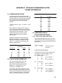
D.1 IMPEDANCE MATCHING
TABLE D.2-1. Pout Values
The reflected power to forward power ratio
shows the degree of impedance match between
the transmitter and the cable/antenna assembly.
The percent of power reflected approximates
the impedance match with the following
equation:
FWD
110
130
150
165
175
185
195
205
215
230
250
2
% power reflected = [((ref + 17.4)/(fwd + 17.4))
x 100] - 1
This equation is an approximation because
some of the power reflected to the transmitter
can be reflected back to the antenna and then
reflected back to the transmitter. These
multiple reflections can cause incorrect
readings, especially when the reflected
power is large.
Pout (dBm)
+35.9
+37.2
+38.3
+39.0
+39.5
+39.9
+40.4
+40.8
+41.1
+41.7
+42.4
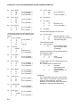
D.3 IMPEDANCE MATCH
DATALOGGER PROGRAM
D.3.1 CR10X, CR10, CR510, AND CR500
Impedance matching is also measured as
reflection coefficient (Γ), Voltage Standing
Wave Ratio (VSWR), and Return Loss (RL).
Table D.1-1 correlates values between the
different measurements.
;
*Table 1 Program
01:
10.0
Table D.1-1. Impedance Matching
Correlation
% power ref
1
2
5
10
20
50
80
Γ
0.1
0.14
0.22
0.32
0.44
0.71
0.89
VSWR
1.2
1.3
1.6
1.9
2.6
5.8
17.9
This example calculates the percent of power
reflected and the amount of power going out to
the transmitter if the percent of power reflected
is less than 5.
RL
20
17
13
10
7
3
1
D.2 CALCULATING POWER-OUT
The amount of power going out of the
transmitter at the BNC connector is
approximated by the following equation:
;USER DEFINED PROGRAM
;Calculate the percent of power reflected with
this equation: % power reflected = [((ref
+17.4)/(fwd + 17.4))^2 x 100] -1
01: Z=X+F (P34)
1:
5
X Loc [ RefPwr ]
2:
17.4
F
3:
8
Z Loc [ RefPlus ]
02:
Approx Pout = (10 log[((fwd + 17.4) x
2
0.0100077) x 1000/50]) + 20.8
This equation assumes the dBm is 50 ohms
and the impedance match between the transmitter and the cable/antenna assembly is good
(% power reflected less than 5). Table D.2-1
lists Pout for various values of forward power.
Execution Interval
(seconds)
03:
Z=X+F (P34)
1:
4
2:
17.4
3:
9
X Loc [ FwdPwr ]
F
Z Loc [ FwdPlus ]
Z=X/Y (P38)
1:
8
2:
9
3:
10
X Loc [ RefPlus ]
Y Loc [ FwdPlus ]
Z Loc [ Scratch1 ]
D-1
APPENDIX D. DETAILED FORWARD/REFLECTED POWER INFORMATION
04:
05:
06:
Z=X*Y (P36)
1:
10
2:
10
3:
10
X Loc [ Scratch1 ]
Y Loc [ Scratch1 ]
Z Loc [ Scratch1 ]
Z=X*F (P37)
1:
10
2:
100
3:
10
16:
Else (P94)
X Loc [ Scratch1 ]
F
Z Loc [ Scratch1 ]
17:
Z=X+F (P34)
1:
10
2:
-1
3:
7
Z=F (P30)
1:
0
2:
0
3:
6
X Loc [ Scratch1 ]
F
Z Loc [ PerRef ]
18:
15:
Z=X+F (P34)
1:
11
2:
20.8
3:
6
X Loc [ Scratch2 ]
F
Z Loc [ Fwd_dBm ]
F
Exponent of 10
Z Loc [ Fwd_dBm ]
End (P95)
;Set the Output Flag High (10) every hour
;Calculate the amount of forward power going
out to the transmitter if the % reflected is less
than 5.
07: IF (X<=>F) (P89)
1:
7
X Loc [ PerRef ]
2:
4
<
3:
5
F
4:
30
Then Do
08:
09:
10:
11:
Z=F (P30)
1:
99.923
2:
0
3:
11
F
Exponent of 10
Z Loc [ Scratch2 ]
Z=1/X (P42)
1:
11
2:
11
X Loc [ Scratch2 ]
Z Loc [ Scratch2 ]
Z=X*Y (P36)
1:
4
2:
11
3:
11
X Loc [ FwdPlus ]
Y Loc [ Scratch2 ]
Z Loc [ Scratch2 ]
Z=X*Y (P36)
1:
11
2:
11
3:
11
X Loc [ Scratch2 ]
Y Loc [ Scratch2 ]
Z Loc [ Scratch2 ]
19:
If time is (P92)
1:
0
2:
60
3:
10
Minutes (Seconds --) into a
Interval (same units as above)
Set Output Flag High
;Timestamp hourly data
20: Real Time (P77)
1:
220
Day,Hour/Minute (prev
day at midnight, 2400
at midnight)
;Sample the percent of power reflected and the
forward power in dBm.
21: Sample (P70)
1:
2
Reps
2:
6
Loc [ dBmFwd ]
;Transfer data to the TGT1 when Output Flag is
set High (10).
22: Data Transfer to GOES (P120)
1:
00
self-timed
buffer/append new
data to old data
2:
4
FWD/Ref Power Loc [
FwdPwr ]
D.3.2 21X
12:
13:
14:
D-2
Z=X*F (P37)
1:
11
2:
20
3:
11
X Loc [ Scratch2 ]
F
Z Loc [ Scratch2 ]
Z=LN(X) (P40)
1:
11
2:
11
X Loc [ Scratch2 ]
Z Loc [ Scratch2 ]
Z=X*F (P37)
1:
11
2:
4.3429
3:
11
X Loc [ Scratch2 ]
F
Z Loc [ Scratch2 ]
The 21X's program is the same as the CR10X,
CR10, CR510, and CR500's, except Instruction
99 has an extra parameter. With this
parameter, you specify the array of data that is
transferred to the buffer (see Section 9.2).
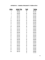
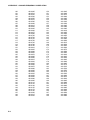
APPENDIX E. CHANNEL/FREQUENCY CORRELATION
Channel
1
2
3
4
5
6
7
8
9
10
11
12
13
14
15
16
17
18
19
20
21
22
23
24
25
26
27
28
29
30
31
32
33
34
35
36
37
38
39
40
41
42
43
44
45
46
47
48
49
Frequency (MHz)
401.7010
401.7025
401.7040
401.7055
401.7070
401.7085
401.7100
401.7115
401.7130
401.7145
401.7160
401.7175
401.7190
401.7205
401.7220
401.7235
401.7250
401.7265
401.7280
401.7295
401.7310
401.7325
401.7340
401.7355
401.7370
401.7385
401.7400
401.7415
401.7430
401.7445
401.7460
401.7475
401.7490
401.7505
401.7520
401.7535
401.7550
401.7565
401.7580
401.7595
401.7610
401.7625
401.7640
401.7655
401.7670
401.7685
401.7700
401.7715
401.7730
Channel
50
51
52
53
54
55
56
57
58
59
60
61
62
63
64
65
66
67
68
69
70
71
72
73
74
75
76
77
78
79
80
81
82
83
84
85
86
87
88
89
90
91
92
93
94
95
96
97
98
99
Frequency
401.7745
401.7760
401.7775
401.7790
401.7805
401.7820
401.7835
401.7850
401.7865
401.7880
401.7895
401.7910
401.7925
401.7940
401.7955
401.7970
401.7985
401.8000
401.8015
401.8030
401.8045
401.8060
401.8075
401.8090
401.8105
401.8120
401.8135
401.8150
401.8165
401.8180
401.8195
401.8210
401.8225
401.8240
401.8255
401.8270
401.8285
401.8300
401.8315
401.8330
401.8345
401.8360
401.8375
401.8390
401.8405
401.8420
401.8435
401.8450
401.8465
401.8480
E-1
APPENDIX E. CHANNEL/FREQUENCY CORRELATION
100
101
102
103
104
105
106
107
108
109
110
111
112
113
114
115
116
117
118
119
120
121
122
123
124
125
126
127
128
129
130
131
132
133
134
135
136
137
138
139
140
141
142
143
144
145
146
147
148
149
E-2
401.8495
401.8510
401.8525
401.8540
401.8555
401.8570
401.8585
401.8600
401.8615
401.8630
401.8645
401.8660
401.8675
401.8690
401.8705
401.8720
401.8735
401.8750
401.8765
401.8780
401.8795
401.8810
401.8825
401.8840
401.8855
401.8870
401.8885
401.8900
401.8915
401.8930
401.8945
401.8960
401.8975
401.8990
401.9005
401.9020
401.9035
401.9050
401.9065
401.9080
401.9095
401.9110
401.9125
401.9140
401.9155
401.9170
401.9185
401.9200
401.9215
401.9230
150
151
152
153
154
155
156
157
158
159
160
161
162
163
164
165
166
167
168
169
170
171
172
173
174
175
176
177
178
179
180
181
182
183
184
185
186
187
188
189
190
191
192
193
194
195
196
197
198
199
401.9245
401.9260
401.9275
401.9290
401.9305
401.9320
401.9335
401.9350
401.9365
401.9380
401.9395
401.9410
401.9425
401.9440
401.9455
401.9470
401.9485
401.9500
401.9515
401.9530
401.9545
401.9560
401.9575
401.9590
401.9605
401.9620
401.9635
401.9650
401.9665
401.9680
401.9695
401.9710
401.9725
401.9740
401.9755
401.9770
401.9785
401.9800
401.9815
401.9830
401.9845
401.9860
401.9875
401.9890
401.9905
401.9920
401.9935
401.9950
401.9965
401.9980
APPENDIX F. DATA DUMP DATALOGGER PROGRAM
F.1 INTRODUCTION
The data dump program inserts 20 data points
(60 bytes) into the transmitter's random buffer
when user FLAG 1 is manually toggled HIGH.
The buffer is cleared when the user FLAG 2 is
set HIGH.
F.2 TOGGLING USER FLAG 1 HIGH
You start by typing in *6AD to enter the FLAG
Status Mode. [00:00:00:00] is displayed,
indicating user FLAGS 1 through 8 are set low.
To toggle user FLAG 1 HIGH, type 1. After the
display shows [10:00:00:00], type *0. When the
data points are in the buffer, [00:00:00:00] is
displayed.
If the display shows [00:00:00:00] before *0 is
typed, the data dump failed. To try again, type
a 1 and a *0. Twenty seconds after the display
shows LOG1, type *6AD. When [00:00:00:00]
is displayed, the data points are in the buffer.
The FLAG Status Mode is exited by setting the
scan rate to 0 (*1A0A) then typing in *0.
F.3 CHECKING THE BUFFER
Check the buffer for the 20 data points (60
bytes) with *#60 commands 7 and 5 (see
Section 8.3). If the display shows a number
other than 60, the data dump failed. You must
then reset the scan rate to 10 and return to the
Flag status mode to set user FLAG 1 HIGH
(see Section F.2).
F.4 TEST TRANSMISSION
CAUTION: The antenna must be
connected before the test or the transmitter
will be damaged.
F.5 TOGGLING USER FLAG 2 HIGH
After the test transmission, the random buffer
MUST BE cleared or the data will be randomly
transmitted throughout the transmission
interval. The buffer is cleared by setting the
scan rate to 10 and typing *6AD2 which sets
user FLAG 2 HIGH. After the display shows
[01:00:00:00], type in *0. If [00:00:00:00] is
shown before *0 is typed, you must type in a 2
and a *0. After waiting twenty seconds, set the
scan rate to 0 and check the buffer with *#60
commands 7 and 5. If a number other than
0000 is displayed, the steps for setting user
FLAG 2 HIGH must be repeated.
F.6 CR10X DATA DUMP PROGRAM
;
*Table 1 Program
01:
10.0
01:
If Flag/Port (P91)
1:
11
Do if Flag 1 is High
2:
30
Then Do
02:
Do (P86)
1:
10
Set Output Flag High
Sample (P70)
1:
20
2:
1
Reps
Loc [ Data
03:
]
;Transfer "test" data of 20 zeros (60 bytes) to
Random buffer for test transmission
04: Data Transfer to GOES (P120)
1:
11
random buffer/overwrite
the old data
2:
1
FWD/Ref Power Loc
[ Data
]
05:
To cause the TGT1 to transmit, use *#60
command 8. The transmission will last less than
5 seconds. To verify transmission occurred,
check forward and reflected power
(*#60 command 3). The TGT-1 will not perform
a test transmission more often than once each
minute.
Execution Interval (seconds)
Do (P86)
1:
21
Set Flag 1 Low
06:
End (P95)
07:
If Flag/Port (P91)
1:
12
Do if Flag 2 is High
2:
30
Then Do
F-1
APPENDIX F. DATA DUMP DATALOGGER PROGRAM
;Clear Random buffer to prevent random
transmissions.
08: Data Transfer to GOES (P120)
1:
11
random buffer/overwrite
the old data
2:
1
FWD/Ref Power Loc
[ Data
]
09:
10:
Do (P86)
1:
22
Set Flag 2 Low
End (P95)
F.7 21X DATA DUMP PROGRAM
The 21X's program is the same as the CR10X
and CR10's, except Instruction 99 has an extra
parameter. With this parameter, you specify the
array of data that is transferred to the buffer
(see Section 9.2).
F-2
APPENDIX G. LOCAL MAGNETIC DECLINATION
A general map showing magnetic declination for
the contiguous United States is shown in Figure
G-1. Magnetic declination for a specific site can
be obtained from a USGS map, local airport, or
through a computer service offered by the
USGS called GEOMAG (recommended).
Section G.2 has a listing of the prompts and the
declination determined by GEOMAG for a site
near Logan, Utah.
G.1 DETERMINING TRUE NORTH
Orientation of the antenna is done after the
location of True North has been found.
1. Establish a reference point on the horizon
for True North (or other direction relative to
True North). True North is usually found by
reading a magnetic compass and applying
the correction for magnetic declination as
discussed below. Other methods employ
observations using the North Star or the
sun, and are discussed in the Quality
Assurance Handbook for Air Pollution
Measurement Systems, Volume IV Meteorological Measurements4.
Declination angles east of True North are
considered negative, and are subtracted from 0
degrees to get True North as shown in Figure
G-2. Declination angles west of True North are
considered positive, and are added to 0 degrees
to get True North as shown in Figure G-3.
Subtract declination from 360°
Add declination to 0°
20 W
22 E
18 W
16 W
20 E
14 W
12 W
18 E
10 W
8 W
16 E
6 W
4 W
14 E
2 W
0
12 E
10 E
8 E
6 E
4 E
2 E
FIGURE G-1. Magnetic Declination for the Contiguous United States
G.2 PROMPTS FROM GEOMAG
GEOMAG is accessed by calling 1-800-3582663 with a computer and telephone modem,
and communications program such as TERM or
GraphTerm (PC208 Software). GEOMAG
prompts the caller for site latitude, longitude,
and elevation, which it uses to determine the
magnetic declination and annual change. The
following Menu and prompts are from
GEOMAG:
MAIN MENU
Type
Q for Quick Epicenter Determinations (QED)
L for Earthquake Lists (EQLIST)
M for Geomagnetic Field Values (GEOMAG)
X to log out
Enter program option: M
Would you like information on how to run
GEOMAG (Y/N)? N
G-1
APPENDIX G. LOCAL MAGNETIC DECLINATION
Options:
Annual change:
1 = Field Values (D, I, H, X, Z, F)
2 = Magnetic Pole Positions
3 = Dipole Axis and Magnitude
4 = Magnetic Center
[1] : 1
0 -6.1
Display values twice
Name of field model
return
Date
return
Latitude
Longitude
Elevation
Units (m/km/ft)
[N]: press return
[USCON90]: press
[current date]: press
The declination in the example above is listed
as 15 degrees and 59.6 minutes. Expressed in
degrees, this would be 15.99 degrees. As
shown in Figure G-1, the declination for Utah is
east, so True North for this site is 360 - 15.99,
or 344 degrees. The annual change is -6.1
minutes.
: 42/2 N
: 111/51/2 W
: 4454
: ft
Example of report generated by GEOMAG:
Model: USCON90
Date : 7/27/93
Latitude: 42/2 N
Longitude: 111/51/2 W
Elevation: 4454.0 ft
D
deg min
15 59.6
FIGURE G-2. Declination Angles East
of True North
FIGURE G-3. Declination Angles West
of True North
G-2
APPENDIX H. CHANGING THE CR10'S RAM OR PROM CHIPS
This section describes changing the CR10’s
PROM, not the CR10X’s. The CR10X already
contains the Instructions for the DCP100.
straighten it and repeat the installation
procedure.
H.2.1 CHANGING JUMPERS
The CR10 has two sockets for Random Access
Memory (RAM) and one socket for
Programmable Read Only Memory (PROM).
The standard CR10 has 64K of RAM, (a 32K
RAM chip in each socket). Earlier CR10s had
16K of RAM (an 8K RAM chip in each socket).
H.1 DISASSEMBLING THE CR10
The sockets provided for RAM and PROM are
located on the CR10 CPU circuit card inside the
CR10 can. To expose the RAM and PROM
sockets, remove the two phillips head screws
from the end opposite the connectors. Remove
the end cap. The ends of two circuit cards and
the RF shield will be visible (see Figure H-1).
Now lay the CR10 on a flat surface, (i.e., a
table), and push on the RF shield with your
thumbs while grasping the can with your hands.
Remove the circuit cards from the can. Orient
the cards with the connector on the left and with
the card that matches Figure H-2. The Central
Processing Unit (CPU) is found at location H-9
and the three slots for RAM and PROM will be
directly beneath it.
H.2 INSTALLING NEW RAM CHIPS IN
CR10S WITH 16K RAM
The two 8K RAM chips are found at locations
C-11 and C-14. With a small flat screw driver
gently pry out the two 8K RAM chips at these
locations and replace them with the 32K RAM
chips provided in the memory upgrade. The
new chips should be installed so the notched
end is towards the nearest card edge. Before
pushing the chips into the socket make certain
that all the pins are correctly seated. After
installing the 32K chips check for pins that may
be bent or not firmly seated in the socket. If you
notice a bent pin, remove the chip, carefully
There are six jumpers used to configure
hardware for different RAM sizes. Figure H-2
shows the jumper settings for different memory
configurations. A pin or small screw driver tip
will work best for pulling these jumpers and
relocating them as shown in Figure H-2.
H.2.2 RAM TEST
Attach the CR10KD Keyboard/Display and apply
power to the CR10. After the CR10 executes
the RAM/PROM self test, the number 96 should
be displayed in the window. The number is the
sum of Kbytes in RAM (64) plus the number of
Kbytes in ROM (32).
H.3 INSTALLING NEW PROM
The PROM chip is found at location C8 on the
CR10 CPU board, (see Figure H-2). With a
small flat screw driver, gently pry out the PROM
chip and replace it with the new one. The new
chip should be installed so that the notched end
is towards the nearest card edge. Before
pushing the chip into the socket make certain
that all the pins are seating correctly. After
installing the chip check for pins that may be
bent or not making contact. If you notice a bent
pin, remove the chip, carefully straighten it and
repeat the installation procedure.
To make certain that the new chip is installed
correctly enter the CR10 *B mode, and advance
to the second window. This window displays
the PROM signature. The five digit number in
the window should match the PROM signature
given with the new PROM documentation. If
the numbers are different disassemble the
CR10 and look for pins that are bent or not
firmly seated.
H-1
APPENDIX H. CHANGING THE CR10'S RAM OR PROM CHIPS
FIGURE H-1. Disassembling CR10
FIGURE H-2. Jumper Settings for Different RAM Configurations
H-2
APPENDIX I. 21X PROM REPLACEMENT PROCEDURE
This appendix covers the procedure for replacing the firmware (PROM) in a Campbell Scientific 21X or
21XL Micrologger. For a nominal fee, Campbell Scientific will install PROMs in 21X(L)s that are returned
to the factory; request a Returned Materials Authorization (RMA) from Campbell Scientific.
CAUTION: This procedure erases data and programs stored in the 21X or 21XL. Before you begin,
transfer to a computer or storage module all data and programs you wish to save. For information
about transferring data and programs between the 21X(L) and a computer, see the 21X(L)
Operator’s Manual.
To prevent components from being damaged by the discharge of static electricity, the PROMs
should be replaced at a grounded work station by a person wearing a grounding strap.
3 4
I.2 PROCEDURE
I.D.
1 2 3 4 5 6
6
H L
7
H L
DATA
PULSE INPUTS
1 2
3 4
21X MICROLOGGER
1. Confirm that all necessary data and
programs stored in the 21X(L) have been
saved to a computer or storage module.
8
H L
S N
10800
6145, 6146, 6147
+12
Pannasonic
2
1 2
CONTROL
Pannasonic
New PROMs
5
H L
SERIAL I O
1
2
4
5
7
*
3
A
6
B
8
9
C
0
#
D
Alkaline
1 2
•
CAO
4
H L
Pannasonic
EXCITATION
3
H L
Alkaline
2
H L
Pannasonic
1
H L
Alkaline
1
Alkaline
PROM puller
or
Flat-bladed screwdriver (shipped with
21X(L))
Pannasonic
•
Pannasonic
Phillips screwdriver #1
Pannasonic
•
Pannasonic
4. Remove the faceplate from the base by
pulling the faceplate straight out from the
base (① on Figure I-2).
I.1 TOOLS REQUIRED
MADE IN USA
1
2. Flip the ON/OFF switch (on the side of the
21X(L)) to the OFF position.
3. Use a Phillips screwdriver to remove the
screws on both sides of the 21X(L)
faceplate (Figure I-1).
1
H L
2
H L
3
H L
4
H L
5
H L
6
H L
7
H L
8
H L
S N
10800
6145, 6146, 6147
EXCITATION
1 2
3 4
CAO
1 2
CONTROL
1 2 3 4 5 6
PULSE INPUTS
1 2
3 4
+12
FIGURE I-2. Separating the Faceplate from
the Base
CAUTION: The faceplate is still connected
to the base by wires from the power supply.
Do not pull the faceplate more than 2” away
from the base.
SERIAL I O
I.D.
DATA
21X MICROLOGGER
1
2
3
A
4
5
6
B
7
8
9
C
*
0
#
D
MADE IN USA
FIGURE I-1. Removing Faceplate Screws
5. Once the faceplate has been disengaged
from the mounting posts, rotate the left side
of the faceplate away from the base to
expose the battery pack (② on Figure I-2).
6. Disconnect the Molex connector to separate
the base from the faceplate (① on Figure I-3).
7. Rotate the faceplate onto its face (② on
Figure I-3).
I-1
APPENDIX I. 21X PROM REPLACEMENT PROCEDURE
1
Firmware
Socket
A
Socket
B
Socket
C
OSX-0.1
OSX-1.1
OSX-2.1
6145-03
6145-03
6145-03
6146-05
6146-05
6146-05
6147-06
6160-05
6161-06
Panasonic
Panasonic
Pannasonic
Panasonic
2
NOTE: Older 21X(L) Microloggers, pre
1986, were shipped with only two 4K RAM
chips (p/n 6116). When these Microloggers
are upgraded to new software PROMs, you
must replace the two 4K chips with five 8K
chips (p/n 6264). You may also need to
reset two jumpers. M15 must be jumpered
on the right set of pins and W20 and W27
must be jumpered on the left set of pins
(see Appendix E in the 21X manual).
3
4
FIGURE I-3. Removing the Back Cover of
the Faceplate
8. Use the Phillips screwdriver to remove the
four screws that hold the back cover to the
faceplate and printed circuit boards (③ on
Figure I-3). The screws are attached to
spacers that may move once the screws
have been removed... so if something
rattles, don’t panic (yet).
9. Remove the back cover of the faceplate (④
on Figure I-3).
11. Use a PROM puller to remove the PROM.
If you don’t have a PROM puller, use the
less elegant procedure described below:
4
3
1
2
84
19
46
61
C
o
mN No
IteObjsl
10. See Figure I-4 and the table below to
determine the PROM(s) you want to
replace. The installed PROMs all have a
notch on the right side. The replacement
PROMs must also be installed with the
notch on the right.
1994
MC74HC4078N
FFDS8929
a) Insert the end of a small flat-bladed
screwdriver underneath the PROM,
then gently rotate the screwdriver to
slightly lift the PROM from the PROM
socket (① on Figure I-5).
1994
ItemNo 6145
ObjsNo 00
CD74HC10E
RCA H 836
C
CD74HC573EX
RCA H 840
1994
CD74HC138EX
RCA H 849
C
ItemNo 6147
ObjsNo 02
MALAYSIA 8807
HM6264LP-15
U0422880
JAPAN 8547
HM6264LPI-15
U0013550
CD4093BEX
RCA H 818
KM6264AL-10
917 KOREA
MALAYSIA 8807
HM6264LP-15
U0422880
MALAYSIA 8803
HM6264ALP-15
03012883
CD74HC00EX
RCA H 923
CD74HC574EX
RCA H 901
CD47HC138EX
RCA H 849
CD74HC174EX
RCA H 745
CD74HC00EX
RCA H 923
CD74HC02EX
RCA H 923
CD74HC393EX
RCA H 901
CD4049BUEX
RCA H 845
CD4020BEX
RCA H 840
CD4053BE
RCA B 731
CD4007UBE
RCA H 910
CD47HC174EX
RCA H 745
CD47HC174EX
RCA H 745
CD74HC574EX
RCA H 901
JAPAN
J
6G1
HD63A03RP
CD4053BE
RCA B 731
C
CD4046BEX
RCA H .919
CD4504BEX
RCA H 910
CD4504BEX
RCA H 910
C
ItemNo 6146
ObjsNo 01
B
A
FIGURE I-5. Removing the PROM with a
Screwdriver
b) Gently pry up the end of the PROM to
about 1/8” off the socket (② on Figure
I-5).
c) Move the screwdriver to the other end
of the PROM and perform the same
procedure (③ and ④ on Figure I-5).
FIGURE I-4. Inside the Faceplate
d) Alternate prying the PROM from either
end. Lift the PROM approximately 1/8”
with each pry until the pins clear the
sockets and the PROM can be lifted out
of the socket.
I-2
APPENDIX I. 21X PROM REPLACEMENT PROCEDURE
12. Hold the new PROM by either end as
shown in Figure I-6. Position the PROM
over the sockets with the circular notch on
the end of the PROM oriented the same
direction as the surrounding PROMs.
84
19 146
6
C No o
m lN
IteObjs
FIGURE I-6. Inserting the New PROM
CAUTION: The notch must be on the right
side. Inserting the PROM in the wrong
direction can damage it.
Set the pins of the PROM on the individual
sockets and press gently. Make sure
individual pins are being inserted straight
into the socket clips and are not bending.
Gently push the PROM in until it seats fully
in the socket.
NOTE: Inspect the PROM assuring that
none of the pins have been bent or are not
in the socket.
13. Repeat steps 9 through 1 (in reverse order)
to reassemble the 21X(L).
I-3
APPENDIX J. TELONICS MODEL TGT1 CERTIFICATION BY
NOAA/NESDIS
J-1
This is a blank page.
Campbell Scientific Companies
Campbell Scientific, Inc. (CSI)
815 West 1800 North
Logan, Utah 84321
UNITED STATES
www.campbellsci.com
[email protected]
Campbell Scientific Africa Pty. Ltd. (CSAf)
PO Box 2450
Somerset West 7129
SOUTH AFRICA
www.csafrica.co.za
[email protected]
Campbell Scientific Australia Pty. Ltd. (CSA)
PO Box 444
Thuringowa Central
QLD 4812 AUSTRALIA
www.campbellsci.com.au
[email protected]
Campbell Scientific do Brazil Ltda. (CSB)
Rua Luisa Crapsi Orsi, 15 Butantã
CEP: 005543-000 São Paulo SP BRAZIL
www.campbellsci.com.br
[email protected]
Campbell Scientific Canada Corp. (CSC)
11564 - 149th Street NW
Edmonton, Alberta T5M 1W7
CANADA
www.campbellsci.ca
[email protected]
Campbell Scientific Ltd. (CSL)
Campbell Park
80 Hathern Road
Shepshed, Loughborough LE12 9GX
UNITED KINGDOM
www.campbellsci.co.uk
[email protected]
Campbell Scientific Ltd. (France)
Miniparc du Verger - Bat. H
1, rue de Terre Neuve - Les Ulis
91967 COURTABOEUF CEDEX
FRANCE
www.campbellsci.fr
[email protected]
Campbell Scientific Spain, S. L.
Psg. Font 14, local 8
08013 Barcelona
SPAIN
www.campbellsci.es
[email protected]
Please visit www.campbellsci.com to obtain contact information for your local US or International representative.