1
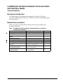
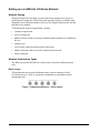
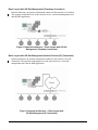
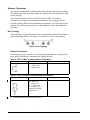
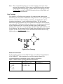
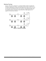
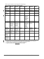
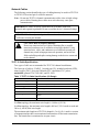
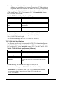
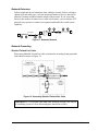
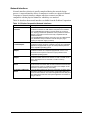
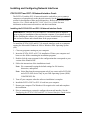
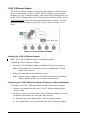
LONWORKS® LN-Series Network Communication and
Interface Guide
Technical Bulletin
Code No. LIT-12011253
Software Release 6.0
Issued January 30, 2013
Supersedes October 6, 2008
Document Introduction . . . . . . . . . . . . . . . . . . . . . . . . . . . . . . . . . . . . . . . . . . . . . . . . . 5
Related Documentation. . . . . . . . . . . . . . . . . . . . . . . . . . . . . . . . . . . . . . . . . . . . . . . . . 5
Setting up a LONWORKS LN-Series Network . . . . . . . . . . . . . . . . . . . . . . . . . . . . . . . . 6
Network Design . . . . . . . . . . . . . . . . . . . . . . . . . . . . . . . . . . . . . . . . . . . . . . . . . . . . . . . . . . 6
Network Architecture Types . . . . . . . . . . . . . . . . . . . . . . . . . . . . . . . . . . . . . . . . . . . . . . . . 6
Basic Layout . . . . . . . . . . . . . . . . . . . . . . . . . . . . . . . . . . . . . . . . . . . . . . . . . . . . . . . . . . . . . 6
Basic Layout with Onsite Management . . . . . . . . . . . . . . . . . . . . . . . . . . . . . . . . . . . . . . . . . 7
Client/Server Architecture (Lightweight Client) . . . . . . . . . . . . . . . . . . . . . . . . . . . . . . . . . . . 7
Basic Layout with Off-Site Management (Telephony Connection) . . . . . . . . . . . . . . . . . . . . 8
Basic Layout with Off-Site Management (Internet Protocol [IP] Connection) . . . . . . . . . . . . 8
Simple Web Browser Based Client . . . . . . . . . . . . . . . . . . . . . . . . . . . . . . . . . . . . . . . . . . . . 9
Network Spanning Local Area Network (LAN) or Wide Area Network (WAN) . . . . . . . . . . . . 9
Network Topologies. . . . . . . . . . . . . . . . . . . . . . . . . . . . . . . . . . . . . . . . . . . . . . . . . . . . . . 10
Bus Topology . . . . . . . . . . . . . . . . . . . . . . . . . . . . . . . . . . . . . . . . . . . . . . . . . . . . . . . . . . . . 10
Network Termination . . . . . . . . . . . . . . . . . . . . . . . . . . . . . . . . . . . . . . . . . . . . . . . . . . . . . . . . . . 10
Free Topology . . . . . . . . . . . . . . . . . . . . . . . . . . . . . . . . . . . . . . . . . . . . . . . . . . . . . . . . . . . 11
Network Termination . . . . . . . . . . . . . . . . . . . . . . . . . . . . . . . . . . . . . . . . . . . . . . . . . . . . . . . . . . 11
Backbone Topology . . . . . . . . . . . . . . . . . . . . . . . . . . . . . . . . . . . . . . . . . . . . . . . . . . . . . . . 12
Communication Protocols . . . . . . . . . . . . . . . . . . . . . . . . . . . . . . . . . . . . . . . . . . . . . . . . 13
Channel Types. . . . . . . . . . . . . . . . . . . . . . . . . . . . . . . . . . . . . . . . . . . . . . . . . . . . . . . . . . . 13
Network Cables . . . . . . . . . . . . . . . . . . . . . . . . . . . . . . . . . . . . . . . . . . . . . . . . . . . . . . . . . 15
TP/FT-10 Cable Specifications . . . . . . . . . . . . . . . . . . . . . . . . . . . . . . . . . . . . . . . . . . . . . . 15
TP/XF-1250 Cable Specifications . . . . . . . . . . . . . . . . . . . . . . . . . . . . . . . . . . . . . . . . . . . . 16
Network Extension. . . . . . . . . . . . . . . . . . . . . . . . . . . . . . . . . . . . . . . . . . . . . . . . . . . . . . . 17
Network Grounding . . . . . . . . . . . . . . . . . . . . . . . . . . . . . . . . . . . . . . . . . . . . . . . . . . . . . . 17
LONWORKS® LN-Series Network Communication and Interface Guide Technical
Bulletin
1
Shielded Twisted Pair Cable . . . . . . . . . . . . . . . . . . . . . . . . . . . . . . . . . . . . . . . . . . . . . . . . 17
Entrance Protection . . . . . . . . . . . . . . . . . . . . . . . . . . . . . . . . . . . . . . . . . . . . . . . . . . . . . . . 18
Network Interfaces. . . . . . . . . . . . . . . . . . . . . . . . . . . . . . . . . . . . . . . . . . . . . . . . . . . . . . . 19
Network Structure . . . . . . . . . . . . . . . . . . . . . . . . . . . . . . . . . . . . . . . . . . . . . . . . . . . . . . . 20
Channels . . . . . . . . . . . . . . . . . . . . . . . . . . . . . . . . . . . . . . . . . . . . . . . . . . . . . . . . . . . . . . . 20
Routers . . . . . . . . . . . . . . . . . . . . . . . . . . . . . . . . . . . . . . . . . . . . . . . . . . . . . . . . . . . . . . . . 20
Multi-port Router . . . . . . . . . . . . . . . . . . . . . . . . . . . . . . . . . . . . . . . . . . . . . . . . . . . . . . . . . . . . . 21
Repeaters . . . . . . . . . . . . . . . . . . . . . . . . . . . . . . . . . . . . . . . . . . . . . . . . . . . . . . . . . . . . . . 22
Subsystems . . . . . . . . . . . . . . . . . . . . . . . . . . . . . . . . . . . . . . . . . . . . . . . . . . . . . . . . . . . . . 22
Installing and Configuring Network Interfaces. . . . . . . . . . . . . . . . . . . . . . . . . . . . . 23
PCLTA-21PCI and PCC-10 Network Interface Cards . . . . . . . . . . . . . . . . . . . . . . . . . . . 23
Installing the PCLTA-21PCI and PCC-10 Network Interface Cards . . . . . . . . . . . . . . . . . . 23
Configuring the PCLTA-21PCI and PCC-10 Network Interface Cards . . . . . . . . . . . . . . . . 24
i.LON 10 Ethernet Adapter . . . . . . . . . . . . . . . . . . . . . . . . . . . . . . . . . . . . . . . . . . . . . . . . 26
Installing the i.LON 10 Ethernet Adapter . . . . . . . . . . . . . . . . . . . . . . . . . . . . . . . . . . . . . . . 26
Configuring the i.LON 10 Ethernet Adapter IP Address and Security Settings . . . . . . . . . . 26
Configuring the i.LON 10 xDriver Network Interface . . . . . . . . . . . . . . . . . . . . . . . . . . . . . . 28
i.LON 100 Internet Server . . . . . . . . . . . . . . . . . . . . . . . . . . . . . . . . . . . . . . . . . . . . . . . . . 29
Installing the i.LON 100 e.3 Internet Server. . . . . . . . . . . . . . . . . . . . . . . . . . . . . . . . . . . . . 29
Configuring the i.LON 100 e.3 Internet Server IP Address and Security Settings . . . . . . . . 29
Configuring the i.LON 100 xDriver Network Interface . . . . . . . . . . . . . . . . . . . . . . . . . . . . . 31
i.LON 600 LONWORKS/IP Server. . . . . . . . . . . . . . . . . . . . . . . . . . . . . . . . . . . . . . . . . . . . . 32
Installing the i.LON 600 LONWORKS/IP Server. . . . . . . . . . . . . . . . . . . . . . . . . . . . . . . . . . . 32
Configuring the i.LON 600 LONWORKS/IP Server IP Address . . . . . . . . . . . . . . . . . . . . . . . 33
Configuring the i.LON 600 LONWORKS/IP Server. . . . . . . . . . . . . . . . . . . . . . . . . . . . . . . . . 34
Configuring the i.LON 600 LONWORKS/IP Network Interface . . . . . . . . . . . . . . . . . . . . . . . . 35
U/10 and U/20 Network Interfaces . . . . . . . . . . . . . . . . . . . . . . . . . . . . . . . . . . . . . . . . . . 37
Installing the U/10 and U/20 Network Interfaces . . . . . . . . . . . . . . . . . . . . . . . . . . . . . . . . . 37
Detecting the U/10 and U/20 Network Interfaces. . . . . . . . . . . . . . . . . . . . . . . . . . . . . . . . . 37
Configuring the U/10 and U/20 Network Interface Properties . . . . . . . . . . . . . . . . . . . . . . . 38
2
LONWORKS® LN-Series Network Communication and Interface Guide Technical Bulletin
Troubleshooting the LONWORKS LN-Series Network . . . . . . . . . . . . . . . . . . . . . . . . 39
Troubleshooting Using Device Status LEDs . . . . . . . . . . . . . . . . . . . . . . . . . . . . . . . . . . 40
LONWORKS® LN-Series Network Communication and Interface Guide Technical Bulletin
3
4
LONWORKS® LN-Series Network Communication and Interface Guide Technical Bulletin
LONWORKS® LN-Series Network Communication
and Interface Guide
Technical Bulletin
Document Introduction
Use this document for information on setting up LONWORKS® LN-Series
networks, troubleshooting LONWORKS LN-Series networks, and installing related
network interfaces.
Related Documentation
Table 1 provides a list of documents related to the LN-Series products and
LONWORKS networks.
Table 1: LONWORKS LN-Series Network Communication and Interface
Related Documentation
For Information On
See Document
LIT Number
Installing LN-Builder 3 Software
LN-Builder 3 Installation Instructions
LIT-12011532
Using LN-Builder 3 Software
LN-Builder 3 Technical Bulletin
LIT-12011250
Using the LN-Lighting Controls
System
LN-Light Plug-In User's Guide
LIT-12011217
Installing the LN-Panel
LN-Light Panel Installation Instructions
LIT-12011225
Installing the LN-Display
LN-Display Installation Instructions
LIT-1201904
Installing the LN-Scheduler
LN-Scheduler Installation Instructions
LIT-1201907
LN-Lighting Controls Features and
Benefits
LN-Light Panel, Display, and
Scheduler Product Bulletin
LIT-12011211
Connecting LN-Series Controllers
to the Metasys® System
LONWORKS Network Integration with
NAE Technical Bulletin
LIT-1201668
Installing an MCL Workstation on an
LN-Series Network
MCL Installation and Commissioning
Technical Bulletin
LIT-1201120
LONWORKS® LN-Series Network Communication and Interface Guide Technical Bulletin
5
Setting up a LONWORKS LN-Series Network
Network Design
Network design is the first thing you must plan when starting a new project or
modifying an existing one. Some of the most important factors to consider when
designing a network are the number of devices, the length of the network, and the
network access method.
To determine the network requirements, consider:
•
customer requirements
•
new or existing site
•
number of devices that are currently installed and the number to be installed at
the site
•
multiple sites
•
access to the control system network for the site(s)
•
number of people with access to the control system network
•
future expansion
Network Architecture Types
The following sections describe the various types of network architectures that
exist.
Basic Layout
This architecture has an open distributed control system consisting of only
LONWORKS devices. There is no operator workstation or permanent network
management tool.
Figure 1: Network Architecture — Basic Layout
6
LONWORKS® LN-Series Network Communication and Interface Guide Technical Bulletin
Basic Layout with Onsite Management
This architecture has a single operator workstation that includes the network
operating system, a network management tool, and a Human-Machine Interface
(HMI) application.
Figure 2: Network Architecture — Basic
Layout with Onsite Management
Client/Server Architecture (Lightweight Client)
In the lightweight client architecture, client applications communicate with the
LNS® server computer via the Ethernet to perform network management,
monitoring, and controls tasks.
Figure 3: Network Architecture — Client/Server
Architecture (Lightweight Client)
LONWORKS® LN-Series Network Communication and Interface Guide Technical Bulletin
7
Basic Layout with Off-Site Management (Telephony Connection)
In this architecture, an operator workstation connects to the network via a modem.
The operator workstation acts as the network server, a network management tool,
and an HMI application.
Figure 4: Network Architecture — Basic Layout with Off-Site
Management (Telephony Connection)
Basic Layout with Off-Site Management (Internet Protocol [IP] Connection)
In this architecture, an operator workstation connects to the network via an IP
connection. The operator workstation acts as the network server, a network
management tool, and an HMI application.
Figure 5: Network Architecture — Basic Layout with
Off-Site Management (IP Connection)
8
LONWORKS® LN-Series Network Communication and Interface Guide Technical Bulletin
Simple Web Browser Based Client
In this architecture, the Web-based client performs monitoring and control tasks. A
standard Web browser requests standard Hypertext Markup Language (HTML)
Web pages from the Web server.
Figure 6: Network Architecture —
Simple Web Browser Based Client
Network Spanning Local Area Network (LAN) or Wide Area Network (WAN)
In this architecture, device and network tool traffic is routed across a LAN or
WAN. An i.LON® 600 LONWORKS/IP server performs routing functions that
allow devices on Channel A to communicate with devices on Channel B using an
IP backbone channel.
Figure 7: Network Architecture — Network Spanning
LAN or WAN
LONWORKS® LN-Series Network Communication and Interface Guide Technical Bulletin
9
Network Topologies
The physical routing of the communication channel defines the network topology.
The channel and transceiver type defines the requirements and limitations of each
wiring topology.
Some network segments such as the TP/FT-10 and TP/XF-1250 require
termination for proper data transmission performance. Free topology and bus
network topology differ in their termination requirements. The following sections
describe the various network topologies, their terminator types, and termination
procedures.
Bus Topology
A bus topology is a physical routing of the communication channel that includes a
distinct beginning and end. This type is also known as a daisy-chain topology.
Figure 8: Bus Topology
Network Termination
For bus topology type networks, use the following terminators at each end of the
bus topology channel (two terminators per channel in total):
Table 2: TP/FT-10 Bus Topology Network Termination
Termination
+
C1
Requirements
Johnson Controls® Part No.
R1 = 105Ω, ±1%, 1/8 W
C1 = 100µF, ≥ 50 V
C2 = 100µF, ≥ 50 V
NXM-TERM-FTT
R1
C2
+
Table 3: TP/XF-1250 Bus Topology Network Termination
Termination
R1
C1
R2
C2
Requirements
Johnson Controls Part No.
R1 = 59Ω, ±1%
R2 = 340Ω, ±1%
R3 = 102Ω, ±1%
C1 = 0.15µF, ±10%*
C2 = 0.33µF, ±10%*
*Capacitors are metal
polyester, 50 V
NXM-TERM-12501
R3
1.
10
The NXM-TERM01250 is a discontinued product.
LONWORKS® LN-Series Network Communication and Interface Guide Technical Bulletin
Note: The recommended topology to use when designing a network is a bus
topology. Bus topologies are the easiest to troubleshoot and the maximum
wiring length in a bus topology is greater than in a free topology. See the
Channel Types section for detailed information about wiring lengths and
network cable considerations.
Free Topology
Free topology is a flexible wiring structure for communication channels that
include ring, star, loop and/or combination wiring structures. A free topology does
not have restrictions such as branching restrictions, stub length limits, device
separation requirements, or strict termination guidelines. The free topology
transmission specification has only two requirements that must be met for proper
system operation. The distance from each transceiver to all other transceivers and
to the termination must not exceed the maximum node-to-node distance. If
multiple paths exist (that is, a loop topology), then the longest path should be used
for calculations. The maximum total wire length is the total length of wire within a
segment. See the Network Cables section for detailed information about wiring
lengths and network cable considerations.
T
Figure 9: Free Topology
Network Termination
For free topology type networks (TP/FT-10 only), use Johnson Controls Part No.
NXM-TERM-FTT as the terminator for each free topology channel. We
recommend placing the terminator near the router for consistency.
Table 4: TP/FT-10 Free Topology Network Termination
Termination
+
C1
Requirements
Johnson Controls Part No.
R1 = 52.3Ω, ±1%, 1/8 W
C1 = 100µF, ≥ 50 V
C2 = 100µF, ≥ 50 V
NXM-TERM-FTT
R1
C2
+
LONWORKS® LN-Series Network Communication and Interface Guide Technical Bulletin
11
Backbone Topology
Routers connect device channels to a common backbone channel. Typically, the
backbone is a high-speed channel, such as high-speed twisted pair, TP/XF-1250, or
LONWORKS/IP. Each device channel can have either a free or bus topology. It is not
necessary that each channel have the same topology. The guidelines for bus and
free topologies (that is, termination requirements and wiring length) must be
applied to each individual channel.
Figure 10: Backbone Topology
12
LONWORKS® LN-Series Network Communication and Interface Guide Technical Bulletin
Communication Protocols
A LONWORKS network is based on the LonTalk® communication protocol
(American National Standards Institute [ANSI]/Electronic Industries Alliance
[EIA]/Consumer Electronic Association [CEA]-709.1 standard). This protocol
defines the format of the message being transmitted between devices and defines
the actions expected when one device sends a message to another. The protocol
ensures that application data on a source device is correctly received by the
applications on one or more destination devices.
Channel Types
Table 5 explains the most commonly used LONWORKS channel types. Different
channel types can be connected using a LonTalk router.
Table 5: Channel Types
Channel Type
Description
TP/FT-10
A Free Topology channel is typically used at the device level. Use
Echelon® Free Topology Transceivers FTT-10A or FT-X1 on a TP/FT-10
channel.
TP/LP-10
A Link Power channel is typically used at the device level. On a TP/LP-10
channel, devices are powered by the communication channel itself using
the communication conductors.
TP/XF-1250
A 1250 high-speed channel is typically used as a network backbone.
LONWORKS IP
A LONWORKS IP channel is typically used as a network backbone. The
reach of a LONWORKS IP channel can easily be extended beyond the LAN
to the Internet for remote management tasks.
FO-10
A Fiber Optical channel is typically used as a network backbone. A FO-10
channel is used in applications where a long network is required (for
example, a large university campus). The maximum cable length for a
FO-10 channel is 30 km (19 mi). Special tools and training are required for
conditioning and connecting the fiber.
PL-10 and PLT-22
PL-10 and PLT-22 channels allow you to communicate over a high voltage
powerline channel. These channels allow you to use your building’s
existing electrical AC wiring for communications.
LONWORKS® LN-Series Network Communication and Interface Guide Technical Bulletin
13
Table 6 provides details on and compares the channel types.
Table 6: Channel Type Details and Comparison
Channel
Detail
TP/FT-10
TP/LP-10
TP/XF-1250
PLT-22
LONWORKS
IP
FO-10
Common
Name
Free Topology
Link Power
Twelve Fifty
Powerline
N/A
Fiber
Typical Use
Node Level1
Node Level
Backbone2
Node Level
Backbone
Backbone
Raw Bite
Rate
78 kbps
78 kbps
1.25 Mbps
N/A
N/A
Close to
TP/XF-1250
Packets Per
Second
144/168
144/168
747/835
14 (Typical)
> 5000 pkts/s
Close to
TP/XF-1250
Peak Traffic3
180/210
180/210
933/1043
20
(CENELEC4
protocol
disabled), 18
(CENELEC4
protocol
enabled)
N/A
Close to
TP/XF-1250
Topology
Free, Bus
Free, Bus
Bus
Free, Bus
Bus
Bus
Termination
Yes; One per
segment in
Free topology
or two per
segment in
Bus topology
Yes; One per
segment in
Free topology
or two per
segment in
Bus topology
Both Ends
Special
applications
only (long haul
or lightly
loaded
powerline
network)
Ethernet
Standard
N/A
Maximum
Total Cable
Length5
Bus = 2,700 m
(8,858 ft)
Free = 500 m
(1,640 ft)
Bus = 2,700 m
(8,858 ft)
Free = 500 m
(1,640 ft)
130 m
(427 ft)
Kilometers
(Miles)
Unlimited
(Worldwide
Internet or
Local LAN)
30 km
(19 mi)
Maximum
Stub Length
Bus = 3 m
(10 ft)
Bus = 3 m
(10 ft)
0.3 m (1 ft)
N/A
N/A
N/A
Maximum
Device-toDevice
Distance
Free = 500 m
(1,640 ft)
Free = 500 m
(1,640 ft)
130 m
(427 ft)
N/A
N/A
N/A
Maximum
Number of
Devices Per
Segment
64
128
64
N/A
N/A
Hundreds
1.
2.
3.
4.
5.
14
Node level refers to the communication segment at the node level.
Backbone refers to the main data communication segment that is usually common to all other segments.
Peak traffic refers to the peak packets per second limits for the media type defined.
European Committee for Electrotechnical Standardization (CENELEC)
Subject to cable type. See the Network Cables section for details.
LONWORKS® LN-Series Network Communication and Interface Guide Technical Bulletin
Network Cables
The following section identifies the type of cabling that may be used in a TP/FT-10
or TP/XF-1250 twisted pair LONWORKS network.
Note: Do not run TP/FT-10 channel communication cables close to high voltage
power cables. Running these cables near each other may cause poor
communication.
IMPORTANT: Make all wiring connections in accordance with local,
national, and regional regulations. Do not exceed the device’s electrical ratings.
IMPORTANT: Use only twisted pair cable or wire and conductors on a
LONWORKS twisted pair channel.
CAUTION: Risk of Property Damage.
Do not use untwisted wires or cables containing flat or parallel
untwisted conductors on a LonWorks twisted pair channel. Using
untwisted wire, cable, and conductors on a LonWorks twisted pair
channel may result in improper network operation, and an electric
field can build up and spike causing damage to the devices connected
to the channel.
!
TP/FT-10 Cable Specifications
Two types of cable are recommended for TP//FT-10 channel installations.
The first type of cable is 22 AWG, 1 twisted pair (1P), stranded conductor (STR),
tinned copper (TNC), Polyvinyl Chloride (PVC) insulation, PVC jacket,
unshielded, plenum FT6, CSA 600V, and UL 300V.
Table 7: TP/FT-10 Cable Specifications (22 Gauge)
Attributes
Specifications
Conductor Gauge (AWG)
22 AWG
Conductor Count
2 Conductors (Twisted Pair)
Conductor Type
Stranded Conductor
Material
Tinned Copper
Plenu
Plenum Rated
NEC Rating
UL Listed NEC Article 800 Communications Plenum (CMP)
Rated
CSA
Flame Rated
In a Bus topology, the maximum wire length is 1,400 m (4,593 ft).
In a Free topology, the maximum wire length is 400 m (1,312 ft) node-to-node and
500 m (1,640 ft) total wire length.
The maximum stub length on a TP/FT-10 channel is 3 m (10 ft). A stub is a section
of transmission line that is not terminated and branches off the main transmission
line. The branch line is terminated as an open circuit.
LONWORKS® LN-Series Network Communication and Interface Guide Technical Bulletin
15
Note: If you exceed the limits for the number of transceivers or total wire
distance, you can add one Free Topology Transceiver (FTT) physical layer
repeater to connect two segments and double the overall system capability.
The second type of cable is 16 AWG, 1 twisted pair (1P), stranded conductor
(STR), tinned copper (TNC), PVC insulation, PVC jacket, unshielded, plenum
FT6, CSA 600V, and UL 300V.
Table 8: TP/FT-10 Cable Specifications (16 Gauge)
Attributes
Specifications
Conductor Gauge (AWG)
16 AWG
Conductor Count
2 Conductors (Twisted Pair)
Conductor Type
Stranded Conductor
Material
Tinned Copper
Plenu
Plenum Rated
NEC Rating
UL Listed NEC Article 800 Communications Plenum (CMP)
Rated
CSA
Flame Rated
In a Bus topology, the maximum wire length is 2,700 m (8,858 ft).
In a Free topology, the maximum wire length is 400 m (1,312 ft) node-to-node and
500 m (1,640 ft) total wire length.
The maximum stub length on a TP/FT-10 channel is 3 m (10 ft).
TP/XF-1250 Cable Specifications
The following type of cable is recommended for TP//FT-10 channel installations:
22 AWG, 1 twisted pair (1P), stranded conductor (STR), tinned copper (TNC),
PVC insulation, PVC jacket, unshielded, plenum FT6, CSA 600V, and UL 300V.
Table 9: TP/XF-1250 Cable Specifications (22 Gauge)
Attributes
Specifications
Conductor Gauge (AWG)
22 AWG
Conductor Count
2 Conductors (Twisted Pair)
Conductor Type
Stranded Conductor
Material
Tinned Copper
Plenu
Plenum Rated
NEC Rating
UL Listed NEC Article 800 Communications Plenum (CMP)
Rated
CSA
Flame Rated
In a Bus topology, the maximum wire length is 130 m (427 ft).
The maximum stub length on a TP/XF-1250 channel is 0.3 m (1 ft).
IMPORTANT: In accordance with TP/XF-1250 communication standards,
do not use more than 8 transceivers per 16 m (52.5 ft) of cable on a
TP/XF-1250 channel.
16
LONWORKS® LN-Series Network Communication and Interface Guide Technical Bulletin
Network Extension
Follow length and device limitations when cabling a network. Before selecting a
channel type and cable type, verify the maximum number of devices that can be
added to a channel and the maximum length of the network. If you exceed the
limits for the number of transceivers or total wire distance, you can add one FTT
physical layer repeater to connect two segments and double the overall system
capability.
Bus Toplogy
T
T
Re pea te r
or
R outer
...
T
T
Bus Toplogy
...
Figure 11: Extended Network
Network Grounding
Shielded Twisted Pair Cable
When using Shielded Twisted Pair cable, terminate the twisted pair and ground the
cable shield as shown in Figure 12.
Figure 12: Grounding Shielded Twisted Pair Cable
IMPORTANT: Use shielded cable only when installing network cable outside
of a building to protect it from Electromagnetic Interference (EMI).
LONWORKS® LN-Series Network Communication and Interface Guide Technical Bulletin
17
Ground the cable shield using a capacitor to tie the shield to earth ground and use a
large value resistor to bleed off any static charge on the shield.
Tie the shield to earth ground through a capacitor, instead of with a direct
connection. This prevents DC and 50/60 Hz ground paths from forming through
the shield. Typical values for Cc and Rb are as follows:
Cc = 0.1 µF, 10%, Metalized Polyester, ≥ 100 V
Rb = 470 k≥, 1/4 W, ±5%
Ground the cable shield at least once per segment, preferably at each node.
Grounding the shield at every node (using the shield grounding circuit shown in
Figure 12) helps suppress 50/60 Hz standing waves.
Entrance Protection
Use shielded twisted pair wire for networks, or portions of networks, that are run
outside of buildings. Connect the shield to earth at each building entry point via a
data-line lightning/surge arrester to conduct lightning strike energy or power
surges directly to ground and prevent their entry into the building via the control
systems network. Use data-line lightning/surge arresters at each building entrance
and connect them to the network data lines.
18
LONWORKS® LN-Series Network Communication and Interface Guide Technical Bulletin
Network Interfaces
Network interface selection is usually completed during the network design
process. A network interface allows a computer to connect to a physical channel.
Computer to Network interface adapters must have transceivers that are
compatible with the physical channel to which they are attached.
Table 10 describes the network interfaces available from the Echelon Corporation.
Table 10: Echelon Corporation Network Interfaces
Network Interface
Description
U10/U20 USB Network
Interfaces
The U10 and U20 USB Network Interfaces are high-performance
LONWORKS interfaces for USB-enabled computers and controllers.
The U10 USB Network Interface connects directly to a TP/FT-10
Free Topology Twisted Pair (ANSI/CEA-709.3) LONWORKS channel
through a removable connector and is fully compatible with link
powered channels.
The U20 USB Network Interface connects to a PL-20 C-Band Power
Line (ANSI/CEA-709.2) LONWORKS channel through a plug-in
coupling circuit/power supply (included).
PCC-10 PC Card
LonTalk Adapter
The PCC-10 PC Card LonTalk Adapter is a high-performance
LONWORKS interface for laptop, handheld computer, and embedded
applications equipped with a Type II PC Card (PCMCIA) interface
and a compatible operating system.
PCLTA-21 PCI LonTalk
Adapter
The PCLTA-21 PCI LonTalk Adapter is a high-performance
LONWORKS interface for computers equipped with a 3.3 V or 5 V
32-bit Personal Component Interconnect (PCI) interface and a
compatible operating system.
i.LON 10 Ethernet
Adapter
The i.LON 10 Ethernet Adapter is an interface that connects
LONWORKS based devices to the Internet, a LAN, or a WAN. As an
option, this adapter can be used with a modem for dial-up
connectivity.
i.LON 100 e.3 Internet
Server
The i.LON 100 e.3 Internet Server bridges LONWORKS networks and
can be used as an interface that connects LONWORKS based devices
to the Internet, a LAN, or a WAN. As an option, this adapter can be
used with a modem for dial-up connectivity.
i.LON 600 LONWORKS/IP
Server
The i.LON 600 LONWORKS/IP Server is an EIA-852 compliant device
that allows LonTalk to IP communication and provides reliable and
secure access to devices. The i.LON Configuration Server Utility and
the LONWORKS/IP Channels control panel application are needed if
using IP channel.
LONWORKS® LN-Series Network Communication and Interface Guide Technical Bulletin
19
Network Structure
A network structure includes the physical and logical structure. The physical
structure consists of channels, repeaters, routers, and devices. The logical structure
contains subsystems and devices.
The first step to configure the network structure is to create the channels. Each
channel can support up to 127 devices; however, a repeater or a second router with
a new channel is required if you are adding more than 64 devices to a channel. A
router is used to connect each set of two channels together.
Channels
A channel refers to the medium through which information is transmitted from a
sender (or transmitter) to a receiver. Different channel types can have varying
transmission speeds, network topologies, and distance limitations. Each channel
can support up to 127 devices. You can connect multiple channels using routers.
Routers
A router is a networking appliance that forwards data packets toward their
destinations through a process known as routing. Besides directing network traffic,
a router can be used to extend the length of a channel as well as the number of
devices attached to the channel. A router can also be used to connect channels that
use different media (transceiver types) together. Routers are always attached to two
channels (the near side channel and the far side channel).
A single router is usually used to connect two channels, but in certain cases you
may wish to use multiple routers (called redundant routers) between the same pair
of channels. Redundant routers provide fault tolerance because if one of the routers
connecting two channels fails, the other router is still available to forward network
traffic. A router can only act as a redundant router if it is set up as a configured
router (which is the default factory configuration).
20
LONWORKS® LN-Series Network Communication and Interface Guide Technical Bulletin
Multi-port Router
A multi-port router consists of an internal backbone that is not visible or physically
accessible to the user. The internal backbone connects several routers.
You are adding a single physical device to the network when you add a multi-port
router with n number of ports. In LN-Builder 3, you must specify that you are
adding n routers connected by a TP-1250 backbone.
In LN-Builder 3, you must set up the routers as illustrated in Figure 13. The
physical channels connected to the logical routers of the multi-port router share an
internal backbone that you must specify to reflect the device functionality.
Figure 13: Multi-Port Router
LONWORKS® LN-Series Network Communication and Interface Guide Technical Bulletin
21
Repeaters
Use a repeater to extend the limits of a channel. On an FTT-10 channel type,
device count and network length restrictions exist. The maximum number of
devices on a FTT-10 channel is 64. See the Network Cables section for network
length restrictions. These restrictions vary according to the topologies and cable
types being used. When you reach the device count or cable length limit, you can
use a repeater or a router to amplify signal. Using a repeater increases the
maximum network length and increases the limit of the number of devices attached
to a channel. When using a repeater, you can add a maximum of 128 devices to one
FTT-10 channel.
A repeater is a device that is physically attached to the LONWORKS network and is
transparent to the network database.
Subsystems
Subsystems allow you to break large networks into more manageable parts in the
software. For example, when creating a control network, each subsystem can
represent each floor of the building. Alternately, each subsystem can contain a
complete air system including the Air Handling Unit (AHU) and its associated
Variable Air Volume (VAV) box. Use subsystems to organize devices. Subsystems
are not physical components and have no relation to network communications.
22
LONWORKS® LN-Series Network Communication and Interface Guide Technical Bulletin
Installing and Configuring Network Interfaces
PCLTA-21PCI and PCC-10 Network Interface Cards
The PCLTA-21 and the PCC-10 network interface cards allow you to connect a
computer or a laptop directly to the physical network. See the Network Interfaces
section for descriptions of these network interfaces. Refer to the PCLTA-21PCI
Interface User’s Guide and the PCC-10 PC Card User’s Guide for more
information on these network interfaces and their installation.
Installing the PCLTA-21PCI and PCC-10 Network Interface Cards
IMPORTANT: The PCLTA-21PCI and PCC-10 software must be installed
prior to physical installation of the card into the computer. If you install the card
before installing the software, the card may become unusable until you uninstall
the card and software and reinstall them in the proper manner.
To install the PCLTA-21PCI and PCC-10 network interface cards on a computer
running the Microsoft® Windows® 2000 or Windows XP® Operating System
(OS):
1. Close any programs running on your computer.
2. Insert the PCLTA-21PCI or PCC-10 installation CD into your computer and
browse to the folder containing the installation programs.
3. Double-click the setup program for the configuration that corresponds to your
version of the Windows OS.
4. Follow the instructions of the installation wizard.
Note: We recommend keeping the default settings for file location,
directories, and options.
Note: Select No when the setup program asks if you want to add a PCCLON1
and a PCCLON2 device entry in your Disk Operating System (DOS)
CONGFIG.SYS file.
5. Turn off your computer when the software installation is complete.
6. Install the PCLTA-21PCI or PCC-10 card into your computer.
7. Restart your computer. The Windows OS recognizes the card and completes
the installation.
8. Prior to connecting to a network, configure the network interface. See the
Configuring the PCLTA-21PCI and PCC-10 Network Interface Cards section.
LONWORKS® LN-Series Network Communication and Interface Guide Technical Bulletin
23
Configuring the PCLTA-21PCI and PCC-10 Network Interface Cards
To configure the PCLTA-21PCI and PCC-10 network interface cards:
1. From the Start menu, select Settings > Control Panel. The Control Panel opens.
2. Double-click the LONWORKS Plug’n Play icon. The LONWORKS Plug’n Play
dialog box appears (Figure 14).
Figure 14: LONWORKS Plug’n Play Dialog Box
3. Verify that the NI Application field is set to PCC10VNI.
4. Verify that the Automatic Flush Cancel option is selected.
5. Click Transceiver. The Transceiver dialog box appears (Figure 15).
Figure 15: Transceiver Dialog Box
6. Select the transceiver type from the Transceiver drop-down menu. The system
retrieves the transceiver configuration selected.
7. Click OK in the Transceiver dialog box.
24
LONWORKS® LN-Series Network Communication and Interface Guide Technical Bulletin
8. Click Apply in the LONWORKS Plug’n Play dialog box.
9. Click Diagnostics. The Diagnostics dialog box appears.
10. Click Test. The status and error count from the PCLTA-21PCI and PCC-10
card appears (Figure 16 and Figure 17).
Figure 16: Diagnostics Dialog Box — Test with No Errors
Figure 17: Diagnostics Dialog Box — Failed Test
Note: If there is a problem with the network interface, **Failed** appears in
the Diagnostics dialog box (Figure 17). Refer to the network interface
user’s guide to troubleshoot the error.
If the network interface test has no errors (Figure 16), click OK to exit.
Then click OK in the LONWORKS Plug’n Play dialog box.
LONWORKS® LN-Series Network Communication and Interface Guide Technical Bulletin
25
i.LON 10 Ethernet Adapter
The i.LON 10 Ethernet Adapter is an interface that connects LONWORKS based
devices to the Internet, a LAN, or a WAN. There are multiple steps required to
configure an i.LON 10 Ethernet Adapter. This section briefly describes how to set
up the i.LON 10 adapter and use it as a Remote Network Interface (RNI). See the
Network Interfaces section for a description of this network interface. For more
information about this adapter, refer to the i.LON 10 Ethernet Adapter User’s
Guide.
Figure 18: i.LON 10 Ethernet Adapter
Installing the i.LON 10 Ethernet Adapter
Note: The i.LON 10 Ethernet Adapter is an obsolete product.
To install the i.LON 10 Ethernet Adapter:
1. Insert the i.LON 10 Ethernet Adapter installation CD into your computer.
Note: If the installation wizard fails to start, browse through the CD and
double-click setup.exe.
2. Follow the instructions in the installation wizard.
Note: After the setup is complete, visit the Echelon Web site to download
software updates at: http://www.echelon.com/downloads
Configuring the i.LON 10 Ethernet Adapter IP Address and Security Settings
To configure the i.LON 10 Ethernet Adapter IP address and security settings:
1. Connect your computer directly to the i.LON 10 Ethernet Adapter using a
crossover cable.
2. Perform a security access reset on the i.LON 10 Ethernet Adapter to reset the
IP address to the default value and enable other features:
a. Disconnect the power adapter of the i.LON 10 Ethernet Adapter.
b. Press and hold the service pin switch of the i.LON 10 Ethernet Adapter.
26
LONWORKS® LN-Series Network Communication and Interface Guide Technical Bulletin
c. Reapply power to the i.LON 10 Ethernet Adapter while continuing to hold
the service pin until the wink and connect Light-Emitting Diodes (LEDs)
illuminate (10 seconds).
Note: When the LEDs illuminate, it means that the security access reset has
been performed properly.
3. To communicate with the i.LON 10 Ethernet Adapter, verify that your
computer is on the same subnet as the i.LON 10 adapter, which is 192.168.1.x.
If the computer’s subnet is different, open a DOS command prompt and type in
the following command: route add 192.168.1.0 mask 255.255.255.0
%computername%
4. Open your Internet browser and enter the following address:
http://192.168.1.222/config/
5. Select the General tab from the menu bar of the i.LON 10 Ethernet Adapter
properties screen (Figure 19).
Figure 19: i.LON 10 Properties Screen — General Tab
6. Set the user name and password when prompted.
7. Set the Transmission Control Protocol (TCP)/IP parameters.
8. We recommend that you disable the following security options:
•
Allow HTTP Access
•
Allow TFTP Access
•
Allow Access to Secure Pages Without Security Access Reset
LONWORKS® LN-Series Network Communication and Interface Guide Technical Bulletin
27
9. Click Submit when the configuration is complete.
Note: These parameters take effect after you power cycle to the i.LON 10 device.
Configuring the i.LON 10 xDriver Network Interface
To configure the i.LON 10 xDriver network interface:
1. From the Start menu, select Settings > Control Panel. The Control Panel opens.
2. Double-click the LONWORKS Interfaces icon. The LONWORKS Interfaces
dialog box appears (Figure 20).
Figure 20: LONWORKS Interfaces Dialog Box
3. Click Add to add a new xDriver. The Add Network Interface Wizard appears
(Figure 21).
Figure 21: Add Network Interface Wizard
4. Follow the instructions in the Add Network Interface Wizard to create the new
xDriver.
28
LONWORKS® LN-Series Network Communication and Interface Guide Technical Bulletin
Note: Connect LN-Builder 3 to a remote network by configuring the Network
Connection Settings to the OnNet Management Mode and Network
Attached set to Yes. For instructions on configuring these settings, refer to
the LN-Builder 3 Technical Bulletin (LIT-12011250).
i.LON 100 Internet Server
Note: The i.LON 100 Internet Server is the predecessor to the i.LON
SmartServer.
The i.LON 100 e.3 Internet Server bridges LONWORKS networks and can be used
as an interface that connects LONWORKS based devices to the Internet, a LAN, or a
WAN. As an option, this adapter can be used with a modem for dial-up
connectivity. This section briefly describes how to set up the i.LON 100 e.3
Internet Server and use it as a Remote Network Interface (RNI). See the Network
Interfaces section for a description of this network interface. For more information
about this network interface, refer to the i.LON 100 e.3 Internet Server User’s
Guide.
Figure 22: i.LON 100 e.3 Internet Server
Installing the i.LON 100 e.3 Internet Server
To install the i.LON 100 e.3 Internet Server:
1. Insert the i.LON 100 e.3 Internet Server installation CD into your computer.
Note: If the installation wizard fails to start, browse through the CD and
double-click setup.exe.
2. Follow the instructions in the installation wizard.
Note: After the setup is complete, visit the Echelon Web site to download
software updates at: http://www.echelon.com/downloads
Configuring the i.LON 100 e.3 Internet Server IP Address and
Security Settings
To configure the i.LON 100 e.3 Internet Server IP address and security settings:
1. Connect your computer directly to the i.LON 100 server using an Ethernet
cable.
LONWORKS® LN-Series Network Communication and Interface Guide Technical Bulletin
29
2. Perform a security access reset on the i.LON 100 server to reset the IP address
to the default value and enable other features:
a. Disconnect the power adapter of the i.LON 100 server.
b. Press and hold the service pin switch of the i.LON 100 server.
c. Reapply power to the i.LON 100 server while continuing to hold the
service pin until all of the LEDs illuminate (10 seconds).
Note: When the LEDs illuminate, it means that the security access reset has
been performed properly.
3. To communicate with the i.LON 100 server, verify that your computer is on the
same subnet as the i.LON 100 server, which is 192.168.1.x. If the computer’s
subnet is different, open a DOS command prompt and type in the following
command: route add 192.168.1.0 mask 255.255.255.0 %computername%
4. Open your Internet browser and enter the following address:
http://192.168.1.222/
5. Click Service. A logon dialog box appears.
6. Set the user name to ilon and the password to ilon.
7. Click the Setup tab and select TCP/IP. The LAN/WAN setup page appears
(Figure 23).
Figure 23: i.LON 100 e.3 Internet Server Properties Screen — LAN/WAN
8. Set the TCP/IP parameters.
9. Click Submit when the configuration is complete.
Note: These parameters take effect after you power cycle to the i.LON 100
server.
30
LONWORKS® LN-Series Network Communication and Interface Guide Technical Bulletin
Configuring the i.LON 100 xDriver Network Interface
To configure the i.LON 100 xDriver network interface:
1. From the Start menu, select Settings > Control Panel. The Control Panel opens.
2. Double-click the LONWORKS Interfaces icon. The LONWORKS Interfaces
dialog box appears (Figure 24).
Figure 24: LONWORKS Interfaces Dialog Box
3. Click Add to add a new xDriver. The Add Network Interface Wizard appears
(Figure 25).
Figure 25: Add Network Interface Wizard
4. Follow the instructions in the Add Network Interface Wizard to create the new
xDriver.
Note: Connect LN-Builder 3 to a remote network by configuring the Network
Connection Settings to the OnNet Management Mode and Network
Attached set to Yes. For instructions on configuring these settings, refer to
the LN-Builder 3 Technical Bulletin (LIT-12011250).
LONWORKS® LN-Series Network Communication and Interface Guide Technical Bulletin
31
i.LON 600 LONWORKS/IP Server
The i.LON 600 LONWORKS/IP Server is an EIA-852 compliant device that allows
LonTalk to IP communication and provides reliable and secure access to devices.
You need the i.LON Configuration Server Utility and LONWORKS/IP Channels
control panel application when using an IP channel.
There are multiple steps required to configure an i.LON 600 LONWORKS/IP
Server. This section briefly describes how to set up the i.LON 600 server and use it
as a remote network interface (RNI). See the Network Interfaces section for a
description of this network interface. For more information about this adapter,
refer to the i.LON 600 LONWORKS/IP Server User’s Guide.
Figure 26: i.LON 600 LONWORKS/IP Server
Installing the i.LON 600 LONWORKS/IP Server
To install the i.LON 600 LONWORKS/IP Server:
1. Insert the i.LON 600 LONWORKS/IP Server installation CD into your
computer.
Note: If the installation wizard fails to start, browse through the CD and
double-click setup.exe.
2. Follow the instructions in the installation wizard.
Note: After the setup is complete, visit the Echelon Web site to download
software updates at: http://www.echelon.com/downloads
32
LONWORKS® LN-Series Network Communication and Interface Guide Technical Bulletin
Configuring the i.LON 600 LONWORKS/IP Server IP Address
To configure the i.LON 600 LONWORKS/IP Server IP address:
1. Connect your computer directly to the i.LON 600 server using an Ethernet
cable.
2. To communicate with the i.LON 600 server, verify that your computer is on the
same subnet as the i.LON 600 server, which is 192.168.1.x. If the computer’s
subnet is different, open a DOS command prompt and type in the following
command: route add 192.168.1.0 mask 255.255.255.0 %computername%
3. Open your Internet browser and enter the following address:
http://192.168.1.222/config/
4. From the Setup tab of the i.LON 600 LONWORKS/IP Server screen,
select TCP/IP.
5. Set the user name to ilon and the password to ilon. The TCP/IP setup screen
appears (Figure 27).
Figure 27: i.LON 600 LONWORKS/IP Server Screen
6. Set the TCP/IP parameters.
7. Click Submit when the configuration is complete.
Note: These parameters take effect after you power cycle to the i.LON 600
server.
LONWORKS® LN-Series Network Communication and Interface Guide Technical Bulletin
33
Configuring the i.LON 600 LONWORKS/IP Server
To configure the i.LON 600 LONWORKS/IP Server:
1. From the Start menu, select Echelon i.LON 600 > LONWORKS-IP
Configuration Server. The Echelon LONWORKS IP Configuration Server dialog
box appears (Figure 28).
Figure 28: Echelon LONWORKS IP Configuration
Server Dialog Box
2. Add the i.LON 600 device:
a. Right-click the Channel and select New Device.
b. Type the desired name.
c. Right-click the device and select Device Properties.
d. Set the IP address and the time zone.
e. Repeat these steps for other i.LON 600 devices.
3. Add your computer as a new device by repeating Step 2a-d.
Note: The configuration server interacts with a computer that has a
LONWORKS/IP interface in the same way it interacts with an i.LON 600
device.
4. Right-click the Channel and select Update Members. The icon that represents
the i.LON device and the computer turns green.
Note: LN-Builder 3 must be connected to the network using the
LONWORKS/IP network interface; otherwise, the computer icon is red.
34
LONWORKS® LN-Series Network Communication and Interface Guide Technical Bulletin
Configuring the i.LON 600 LONWORKS/IP Network Interface
To configure the i.LON 600 LONWORKS/IP network interface:
1. From the Start menu, select Settings > Control Panel. The Control Panel opens.
2. Double-click the LONWORKS Interfaces icon. The LONWORKS Interfaces
dialog box appears.
3. Click the IP-852 tab (Figure 29).
Figure 29: LONWORKS Interfaces Dialog Box — IP-852 Tab
4. Click Add to add a new network interface. The Network Interface Add Wizard
appears (Figure 30).
Figure 30: Network Interface Add Wizard
5. Enter a name and IP address.
6. Click OK. The new network interface is created.
LONWORKS® LN-Series Network Communication and Interface Guide Technical Bulletin
35
Note: Connect LN-Builder 3 to a remote network by configuring the Network
Connection Settings to the OnNet Management Mode and Network
Attached set to Yes. For instructions on configuring these settings, refer to
the Defining Network Connection Settings section of the LN-Builder 3
Technical Bulletin (LIT-12011250).
Note: Set up the i.LON 600 device as a router in the network database. Refer to
the Adding a Router section of the LN-Builder 3 Technical Bulletin
(LIT-12011250).
36
LONWORKS® LN-Series Network Communication and Interface Guide Technical Bulletin
U/10 and U/20 Network Interfaces
The U/10 and U/20 USB Network Interfaces are high-performance LONWORKS
interfaces for USB-enabled computers and controllers. There are multiple steps
required to configure these USB network interfaces (USB to TP/FT-10). This
section briefly describes how to install and use the USB network interface. See the
Network Interfaces section for a description of this network interface. For more
information about this interface, refer to the USB Network Interface User's Guide.
Figure 31: U/10 and U/20 USB Network Interface
Installing the U/10 and U/20 Network Interfaces
To install the U/10 or U/20 network interface:
1. Insert the U/10 or U/20 network interface installation CD into your computer.
Note: If the installation wizard fails to start, browse through the CD and
double-click OpenLDV210.exe.
2. Follow the instructions in the installation wizard.
Note: After the setup is complete, visit the Echelon Web site to download
software updates at: http://www.echelon.com/downloads
Detecting the U/10 and U/20 Network Interfaces
To detect the U/10 or U/20 network interface, insert the USB network interface
into a free USB port on your computer. The Windows OS automatically detects
and installs the USB network interface.
LONWORKS® LN-Series Network Communication and Interface Guide Technical Bulletin
37
Configuring the U/10 and U/20 Network Interface Properties
To configure the U/10 or U/20 network interface properties:
1. From the Start menu, select Settings > Control Panel. The Control Panel opens.
2. Double-click the LONWORKS Interfaces icon. The LONWORKS Interfaces
dialog box appears.
3. Click the USB tab (Figure 32).
Figure 32: LONWORKS Interfaces Dialog Box —
USB Tab
4. Note the network interface name.
Note: Connect LN-Builder 3 to a remote network by configuring the Network
Connection Settings to the OnNet Management Mode and Network
Attached set to Yes. For instructions on configuring these settings, refer to
the Defining Network Connection Settings section of the LN-Builder 3
Technical Bulletin (LIT-12011250).
38
LONWORKS® LN-Series Network Communication and Interface Guide Technical Bulletin
Troubleshooting the LONWORKS LN-Series Network
This section describes how to identify and repair typical problems that can occur in
a LONWORKS network.
The following flowchart summarizes the sequence of steps that are required to
troubleshoot LONWORKS networks and devices (Figure 33).
Figure 33: Troubleshooting Flowchart
LONWORKS® LN-Series Network Communication and Interface Guide Technical Bulletin
39
1. Some devices use half-wave rectifier circuits. Verify that consistent polarity is
maintained between all devices and the transformer. Check that the common
terminals of all the controllers are connected and make sure that the 24 V input
of all the controllers are connected.
2. For the auto-reset fuse, disconnect the power, input terminals, and output
terminals. Wait a few seconds to allow the auto-reset fuse to cool down. Check
the power supply and check the input and output wiring. Reconnect the power
without connecting the Input/Output (I/O) terminals. If there is no further
problem indicated by the auto-reset fuse, reconnect the I/O terminals.
3. See the Troubleshooting Using Device Status LEDs section for LED state
descriptions.
4. See the Network Topologies section for more information on network topology,
wire type, wire length, and network termination.
5. Use the Device Manager to view communication errors for devices and
routers. Communication errors can cause many problems in a control process.
For example, if a Rooftop Unit (RTU) controller communicates sporadically
with a Variable Air Volume (VAV) box, the system may not work properly. To
identify communication errors, you can use a protocol analyzer or the Device
Manager to list transmission errors, lost messages, and missed messages.
Troubleshooting Using Device Status LEDs
You can use the device status LEDs for quick troubleshooting of devices. Table 11
describes the possible LED states:
Table 11: Status LEDs
LED State
Description
Off
The device is in normal operation or is not powered. (If the device is
powered and the LED is off, pressing the Service Pin lights up the LED).
On
The device is missing its application binary file (.apb).
Appropriate action: Reload the application binary file.
Repeated Blink
(Some Devices)
The device is in normal operation. The LED blinks with respect to the
device code execution time.
Slow Blink
(1 Second On, 1 Second Off)
The device is not configured.
Appropriate action: Commission the device.
Fast Blink
(0.3 Seconds On, 1 Second Off)
There is a watchdog time out. The application is corrupted.
Appropriate action: Call the device installer, distributor, or manufacturer to
report the problem.
Building Efficiency
507 E. Michigan Street, Milwaukee, WI 53202
Metasys® and Johnson Controls® are registered trademarks of Johnson Controls, Inc.
All other marks herein are the marks of their respective owners. © 2013 Johnson Controls, Inc.
40
LONWORKS® LN-Series Network Communication and Interface Guide Technical Bulletin
Published in U.S.A.
www.johnsoncontrols.com