1
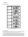
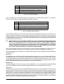
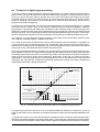
User´s Manual VIRTUALIZER® DSP1000 English Version 1.0 September 1997 The information contained in this manual is subject to change without notice. No part of this manual may be reproduced or transmitted in any form or by any means, electronic or mechanical, including photocopying and recording of any kind, for any purpose, without the express written permission of Behringer GmbH. ALL RIGHTS RESERVED © 1997 Behringer GmbH. BEHRINGER and VIRTUALIZER are registered trademarks of Behringer. BEHRINGER INTERNATIONAL GmbH, Hanns-Martin-Schleyer-Str. 36-38, D-47877 Willich-Münchheide II Tel. +49 (0) 21 54 / 92 06-0, Fax +49 (0) 21 54 / 90 06-30. 1 EG-Declaration of Confirmity Spezielle Studiotechnik GmbH acc. to the Directives 89/336/EWG and 73/23/EWG We, BEHRINGER Spezielle Studiotechnik GmbH Otto-Brenner-Straße 4 D - 47877 Willich Name and address of the manufacturer or the introducer of the product on the market who is established in the EC herewith take the sole responsibility to confirm that the product: VIRTUALIZER DSP1000 Type designation and, if applicable, Article-No which refers to this declaration, is in accordance with the following standards or standardized documents: x EN 60065 x EN 55020 x EN 61000-3-2 x EN 61000-3-3 The following operation conditions and installation arrangements have to be presumed: acc. to Operating Manual Dipl.-Ing. Uli Behringer, President Willich, 29.7.1997 Name, address, date and legally binding signature of the person responsible 2 SAFETY INSTRUCTIONS CAUTION: To reduce the risk of electrical shock, do not remove the cover (or back). No user serviceable parts inside; refer servicing to qualified personnel. WARNING: To reduce the risk of fire or electrical shock, do not expose this appliance to rain or moisture. This symbol, wherever it appears, alerts you to the presence of uninsulated dangerous voltage inside the enclosure - voltage that may be sufficient to constitute a risk of shock. This symbol, wherever it appears, alerts you to important operating and maintenance instructions in the accompanying literature. Read the manual. DETAILED SAFETY INSTRUCTIONS: All the safety and operation instructions should be read before the appliance is operated. Retain Instructions: The safety and operating instructions should be retained for future reference. Heed Warnings: All warnings on the appliance and in the operating instructions should be adhered to. Follow instructions: All operation and user instructions should be followed. Water and Moisture: The appliance should not be used near water (e.g. near a bathtub, washbowl, kitchen sink, laundry tub, in a wet basement, or near a swimming pool etc.). Ventilation: The appliance should be situated so that its location or position does not interfere with its proper ventilaton. For example, the appliance should not be situated on a bed, sofa rug, or similar surface that may block the ventilation openings: or placed in a built-in installation, such as a bookcase or cabinet that may impede the flow of air through the ventilation openings. Heat: The appliance should be situated away from heat sources such as radiators, heat registers, stoves, or other appliance (including amplifiers) that produce heat. Power Source: The appliance should be connected to a power supply only of the type described in the operating instructions or as marked on the appliance. Grounding or Polarization: Precautions should be taken so that the grounding or polarization means of an appliance is not defeated. Power-Cord Protection: Power supply cords should be routed so that they are not likely to be walked on or pinched by items placed upon or against them, paying particular attention to cords and plugs, convenience receptacles and the point where they exit from the appliance. Cleaning: The appliance should be cleaned only as recommended by the manufacturer. Non-use Periods: The power cord of the appliance should be unplugged from the outlet when left unused for a long period of time. Object and Liquid Entry: Care should be taken so that objects do not fall and liquids are not spilled into the enclosure through openings. Damage Requiring Service: The appliance should be serviced by qualified service personnel when: - The power supply cord or the plug has been damaged; or - Objects have fallen, or liquid has been spilled into the appliance; or - The appliance has been exposed to rain; or - The appliance does not appear to operate normally or exhibits a marked change in performance; or - The appliance has been dropped, or the enclosure damaged. Servicing: The user should not attempt to service the appliance beyond that is described in the Operating Instructions. All other servicing should be referred to qualifield service personnel. 3 THE VIRTUALIZER DSP1000 s Ultra-high performance Digital Multi-Effects Processor powerded by a 24-bit high-speed Digital Signal Processor (DSP) s Virtual acoustics reverb algorithms calculated from precise mathematical models of real rooms to give you ultra-natural reverb effects s 32 high quality Reverb, Chorus, Flanger, Delay, Pitch Shifter, Vocoder, Rotary Speaker programs and more s Up to 900 effects variations plus two individual parameters and separate low and high EQ section s Two digital processing engines give you independent or coupled effects on left and right channels s True stereo processing performance allows separation of left and right channels in the stereo field for open-sounding enhancement of the sound sources s 20-bit A/D and D/A converters with 64/128 times oversampling for ultra-high headroom and resolution of detail s Internal 24-bit processing with professional 48 kHz sampling rate s 100 user preset memories to store programs for instant recall s Accurate eight-segment LED level meters simplify level setting for optimum performance s Future-proof software-upgradeable architecture s Full MIDI capability allows real-time parameter control and program selection s Future VIRTUALIZER DESIGN software (free of charge) allows for total remote control via PC s High-quality components and exceptionally rugged construction ensures long life and durability s Internal power supply design for professional application s Made under the stringent ISO9000 quality system standard 4 FOREWORD Dear Customer, Welcome to the team of VIRTUALIZER users and thank you very much for expressing your confidence in Behringer products by purchasing this unit. It is one of my most pleasant tasks to write this letter to you, because it is the culmination of many months of hard work for our engineering team. Our daily objective is to be focused on you, the musician and the sound engineer, and with that focus in mind, it drives us to reach a goal which is unique, and is the backbone of the Behringer philosophy. It is our philosophy to share our joy with you, because you are the most important member of the Behringer family. With your highly competent suggestions for new products you`ve greatly contributed to shaping our company and making it successful. In return, we guarantee you uncompromising quality (manufactured under the stringent quality system ISO9000) as well as excellent technical and audio properties at an extremely favorable price. All of this will enable you to fully unhold your creativity without being hampered by budget constraints. We are often asked how we can make it to produce such high-grade devices at such unbelievably low prices. The answer is quite simple: it`s you, our customers! Many satisfied customers means large sales volumes enabling us to get better conditions of purchase for components, etc. Isn´t it only fair to pass this benefit back to you? Because we know that your success is our success, too! I would like to thank all the people, whose help on the VIRTUALIZER has made it all possible. Everybody has made very personal contributions, starting from the designers of the unit via the many staff members in my company to you, the user of Behringer products. Thank you and sincerely yours, BEHRINGER Spezielle Studiotechnik GmbH Uli Behringer President 5 TABLE OF CONTENT 1. INTRODUCTION..................................................................................................................... 7 1.1 Technical background ...................................................................................................................... 7 1.1.1 Reverberation chambers ........................................................................................................ 8 1.1.2 Spring and plate reverb .......................................................................................................... 9 1.1.3 Digital reverb ......................................................................................................................... 9 1.2 The VIRTUALIZER - concise description ....................................................................................... 10 2. THE CONCEPT .................................................................................................................... 11 2.1 The quality of components and circuits .......................................................................................... 11 2.2 True stereo or stereo effects on a mono input signal? ..................................................................... 11 3. INSTALLATION ..................................................................................................................... 12 3.1 3.2 3.3 3.4 Rack mounting .............................................................................................................................. Mains voltage ................................................................................................................................ Audio connections ........................................................................................................................ Selecting the operating level .......................................................................................................... 12 12 12 13 4. CONTROL ELEMENTS ....................................................................................................... 14 4.1 Front panel control elements ......................................................................................................... 14 4.1.1 Key combinations ............................................................................................................... 15 4.2 Rear panel control elements .......................................................................................................... 16 5. THE EFFECT ALGORITHMS ............................................................................................... 17 6. OPERATION .......................................................................................................................... 20 6.1 6.2 6.3 6.4 6.5 6.6 Effects structure ............................................................................................................................ Selecting presets .......................................................................................................................... Editing programs ........................................................................................................................... Saving programs ........................................................................................................................... MIDI control ................................................................................................................................... The basics of digital signal processing .......................................................................................... 20 20 21 21 21 23 7. APPLICATIONS ..................................................................................................................... 25 7.1 7.2 7.3 7.4 7.5 7.6 Level setting .................................................................................................................................. Using the VIRTUALIZER in the aux bus ........................................................................................ Using the VIRTUALIZER in the insert path .................................................................................... Using the VIRTUALIZER as an effects device for instruments ........................................................ Using the VIRTUALIZER in a MIDI system .................................................................................... Saving data via MIDI ...................................................................................................................... 25 25 26 27 28 28 8. SPECIFICATIONS ................................................................................................................. 29 8.1 Parameter overview ........................................................................................................................ 29 8.2 MIDI Implementation ....................................................................................................................... 30 8.3 Specifications ................................................................................................................................ 31 9. WARRANTY ........................................................................................................................... 32 6 1. INTRODUCTION Since its introduction in the early 80s, artificial digital reverb has been an indispensable standard tool for studio and live applications. Before, professional reverberation could only be produced by using bulky and expensive reverberation plates. With the rapid development of digital technology it has become possible to drastically reduce the price of a good reverb unit, so it is anything but unusual today to find at least one digital reverb device in the racks of P.A. rental companies and recording studios. Owing to their system structure, most digital effects processors are also capable of generating other effects in addition to reverberation. These multieffects processors enable the user to easily produce a maximum variety of effects featuring pro-level audio quality. With the Behringer VIRTUALIZER you have purchased a very powerful multi-effects processor which offers both first-class reverb sounds and various other effect algorithms. Although you will find a high number of effect types - 32 newly developed effect types with more than 900 variations - the VIRTUALIZER can be operated easily and intuitively with its logically structured user interface. The VIRTUALIZER gives you well-known classic effects such as reverb, delay and chorus, plus a broad spectrum of additional programs including such extraordinary effects as "Vocal Distortion", "Rotary Speaker Simulation" or "Vocoder". To be able to fully exploit these effects as well as the other features of the Behringer VIRTUALIZERs innovative virtual acoustics technology, we recommend that you read this users manual carefully. 1.1 Technical background Prior to simulating the physical phenomena of reverberation and reflection, it is necessary to analyze how reverb is generated, and how it is perceived by human hearing. In a concert hall the sound the listener hears comprises both the source signals (e.g. acoustical instruments, P.A. system) and thousands of reflections of these "primary signals", which bounce off floor, ceiling and walls to reach the ear after a short delay. These reflections represent thousands of echos of the direct signal, which are not perceived any longer as single echos but - due to their sheer number - as reverberation. Basically, the reflected signal portions reach the ear later than the source signal, and the very fact that they do not arrive from the same direction as the direct signal (see fig. 1.1), makes it possible to hear spatial information, i.e. to perceive the direct signal as it is embedded in the room acoustics. Direct Sound Stage Ea rly Re ns tio fle cti on rly s ec efl R Ea Listening Position Diffuse Reflections Fig. 1.1: Direct and reflected sounds reaching the listeners ear. 1. INTRODUCTION 7 Spatial information is an important means of orientation, because human hearing is also used to determine the position of a sound source. In certain situations, this capability can be very useful or even of vital importance. The fact that we can actually hear the size of a room shows how strongly developed the human sense of hearing actually is. Based on the reflectivity of a room, we can also distinguish (though we often dont know how) the materials it consists of. In large rooms with high tiled walls reverberation is generally very dense and needs some time to decay, while a small room with many objects in it (furniture, carpets, etc.) features very short reverberation often not even percieved as such. Nevertheless, this extremely short reverb does exist, which is the reason why many designers of reverb devices (such as our VIRTUALIZER ) implement several basic reverb types and give them specific room names. It is quite natural, for example, that a reverb preset called "Cathedral" produces a long and highly dense reverb, while a "Room" program usually represents the acoustics of a room that is much smaller in size. In addition to the capability of human hearing to determine the direction from where a sound phenomenon arrives, we can also hear modulations of acoustic events. Of importance in this context is the frequency of the modulated signals. Frequency modulations below 100 Hz are virtually inaudible. However frequency modulations can clearly be heard when occurring in the midrange frequency band, due to the "sensitivity" of human hearing. The ear immediately detects changes in midrange frequencies, while its sensitivity to frequency modulation in the extreme low end of the frequency spectrum is reduced. Frequency modulation can also be used to produce wanted effects. The popular chorus effect, for instance, is basically the sum of a variety of frequency modulations. The original signal is slightly delayed in the chorus algorithm, then added again and modulated by means of an oscillator. Subsequently, modulating frequencies (of different pitch) are applied to the original signal, which produces the well-known floating chorus sound. Basically, frequency modulation is the starting point for all kinds of chorus-type effects: by simply adding the delayed signal, without modulating the original, you can produce a delay effect. Since chorus effects use very short delay times, the resulting delay effect is not perceived as such. However, when you increase the delay time, there is a clear gap between original and effect signals, and delay becomes audible. A highly intensive effect can be achieved by combining reverb/delay programs with modulation effects. For this reason, the Behringer VIRTUALIZER also features multi-effects programs combining reverb or delay with, for example, a chorus effect. In addition to the multi-effects programs and special-purpose effects, most of the VIRTUALIZERs effect programs offer "pure" reverb programs, because "common" reverb is still the most important effect for mix-down or live applications. Therefore, we at Behringer want to provide you with a variety of reverb programs, so that you have appropriate presets available for each specific application. Before you can simulate any reverb phenomena, you need to identify the major parameters of natural reverberation and use them to create a mathematical algorithm. The Behringer VIRTUALIZER benefits from the newly developed virtual acoustics algorithm. Unlike many other conventional reverb algorithms, the virtual acoustics algorithm reproduces the essential parameters of typical reverb rooms with considerably more detail and realism. 1.1.1 Reverberation chambers Reverberation chambers deliver the most natural form of reverb. In general, every room has its specific acoustic properties which are not only dependent on its size but also on its shape (architecture) and the materials used to construct it. For this reason, experts in architectural acoustics design rooms (concert halls, recording studios, etc.) to produce a specific sound and reverb ambience. Even today almost all recordings of classical music and a major part of jazz recordings are performed in a dedicated recording room. Important professional studios sometimes have special reverberation chambers tuned to produce a specific ambience. They can be built entirely from wood, ceramics or natural stones to generate a specific sound in a very natural way. Some high-end studios even have facilities to adjust the walls and ceilings so as to generate distinct reverb ambiences or sound images. However, as the cost of such rooms are extremely high, newly built studios simply cannot afford a dedicated reverberation chamber. Understandably, no reverb unit can produce reverberation that is more natural in character than the ambience generated by a natural reverberation chamber. On the other hand, reverberation chambers do suffer from three decisive drawbacks: s It is not possible to modify the reverb sound (except for rooms with adjustable walls and ceilings), so when using natural reverb you cannot change its decay time or intensity. s Natural reverberation chambers cannot be used to generate special surreal reverb phenomena, e.g. extremely long decay times or reverse reverb. s Reverberation chambers are not portable! If you wish to use one particular reverb ambience, you will have to record in the specific room that produces it. In a way, each reverberation chamber is unique. 8 1. INTRODUCTION 1.1.2 Spring and plate reverb Due to the disadvantages of natural reverb chambers (see section 1.1.1), two new methods of generating reverb were invented and used in the 50s and 60s. For the first time ever, plate or spring reverb devices allowed for the artificial production of reverberation. A reverb plate consists of a thin steel plate or sturdy metal sheet coated with a gold alloy, which is set in motion by a generator radiating the signal to be processed (reverberated). At another point somewhere on the plate, the signal is picked up by a transducer and then added to the original signal. "Plate" reverb is quite natural in character because the vibrations of the plate are similar to air vibrations in a (reverberation) room, i.e. they are spread in all directions, are reflected when they reach the plate edges, and you can basically distinguish between early and later reflections. The result is an almost natural reverb ambience, however, whose decay time cannot be modified. Room Plate Speaker Sender Microphone Receiver Fig.1.2: Room reflections and reverb plate reflections Spring reverb devices use a similar principle, but their reverb sound is of inferior quality compared to a properly adjusted reverb plate. In particular, dynamic signals such as drums have a highly compressed and "flat" sound when they are reproduced with a spring reverb. Still, spring reverbs can be found even today in guitar amplifiers. Due to the speakers used in such amps, there are no extremely high frequencies to be processed, so lower reverb quality (in particular, in view of the cost) can be an acceptable alternative for guitarists. Yet, spring reverb designs suffer from a few drawbacks limiting their professional use: s The parameters of spring reverb devices cannot be modified or edited. To allow for different reverb decay times, you would need to alter the physical properties of the springs. s The clattering sound of spring reverbs is a much-dreaded effect, in particular, on stage. Shock can set the reverb spring in motion so that it hits against its enclosure. The resulting noise resembles that of thunder. s Spring reverb is of poor quality, especially with percussive signals, which is the reason why the use of such devices in recording studios is highly limited. 1.1.3 Digital reverb With the development of digital reverb devices, spring reverbs and reverb plates have almost completely vanished from the studio, because digital devices feature a wealth of advantages: s Excellent reverb quality. s Mass production allows for reducing the prices of digital reverb devices. s Many parameters can be modified and stored. s With their compact design digital devices are easily portable. s Digital devices need almost no maintenance and are virtually insusceptible to interference. Basically, digital reverberation tries to provide a virtual simulation of real (in specific situations even surreal) reverb phenomena by means of algorithms computed by an effects processor. The quality of this simulation largely depends on the software (algorithms), the performance features of the processor used and the quality of the AD/DA converters. Since natural reverb comprises thousands of single echoes, a fast processor must be used to perform the complex calculations needed. To make the reverb programs sound natural, appropriate software must be used to be able to control the most essential parameters of a reverb phenomenon. For example, signal diffraction, reflections from different kinds of material, phase shift and room resonances must be computed. Consequently, digital devices allow for editing many more parameters than reverb plates or spring reverbs. In almost all digital devices, (at least) the following parameters can be modified: 1. INTRODUCTION 9 s Pre-delay time: this parameter determines the time between the occurrence of original signal and first reflections. s Decay time: determines the duration of the reverb (in seconds). s High-damp: a function that allows for equalizing the reverberated sound in the higher frequency range. To simulate the sound of a heavily damped room, for instance, the high-frequency portions in the reverb signal must be reduced. 1.2 The VIRTUALIZER - concise description The Behringer VIRTUALIZER is a member of the latest generation of multi-effects processors. To generate reverberation that is very natural in character, we at Behringer developed an innovative virtual acoustics technology which allows for computing all room and reverb parameters with absolute pro-level quality and a highly natural sound character. Despite this extensive computing work which is done in the VIRTUALIZER by a "dual-engine" 24 bit processor, the VIRTUALIZER can be operated easily and conveniently. All parameter edits are performed with the jog wheel (rotary control). 100 presets are available to store user-defined programs. However, the VIRTUALIZER is by no means limited to excellent reverb and delay programs. In addition to the simulation of classic plate reverbs, the VIRTUALIZER gives you extraordinary modulation effects (such as chorus and flanger), plus a few special-purpose variants, e.g. a musical pitch shifter as well as tremolo and rotary speaker simulations. With the vocoder and vocal distortion effect programs, you even have ultra-modern special effects available that the VIRTUALIZER generates with absolute high quality. A very special feature are the high-low filters which can be freely edited and directly selected in each preset. With these filters you can fine-tune the sound of your presets to match any given room characteristics - a timesaving feature especially for live applications, where every second counts. The VIRTUALIZER not only features a logical and easy-to-operate user interface but also highly impressive specifications. Top-quality signal processing is ensured by the following characteristics: s Extremely low-noise and high-precision 20-bit AD/DA converters. s The pro-level sampling rate of 48 kHz guarantees high signal resolution over the entire audio spectrum from 20 Hz to 20 kHz. s The 24-bit processor with its two independent sections (dual-engine software) allows for processing each audio channel separately. s Like all Behringer products, the VIRTUALIZER uses exclusive top-quality components and circuits. With its complete MIDI implementation the VIRTUALIZER can be integrated in nearly any MIDI system. A software editor (soon available) enables you to program the VIRTUALIZER from your personal computer, and the MIDI interface allows both for transmittion and external storage of MIDI controller data from the VIRTUALIZER. 10 1. INTRODUCTION 2. THE CONCEPT 2.1 The quality of components and circuits Behringers philosophy guarantees both perfect circuit design and no-compromise selection of components. A 24-bit DSP is used as the heart of the VIRTUALIZER, which is one of the best components available owing to its outstanding specifications and excellent sonic characteristics. Top-quality 20-bit AD/DA converters ensure the high-precision conversion of all signals. Additionally, the VIRTUALIZER uses metal-film resistors and capacitors with very tight tolerances, high-grade switches as well as other select components. The VIRTUALZER VIRTUALIZER was manufactured using SMD technology (Surface Mounted Device). These sub-miniature components known from aerospace applications not only guarantee extremely high packing densities but also increased reliability. Additionally, the VIRTUALIZER was built to meet one of the highest industrial standards - ISO9000. 2.2 True stereo or stereo effects on a mono input signal? For maximum performance and flexibility, we have designed our VIRTUALIZER with two independent processing engines, enabling the following to be achieved: Dual effects programs, processing two completely different signals with individual mono-effects in parallel Parallel processing of two different effects is provided by our dual programs (prg. 25 .. 32) with reverb or echo on the right channel and chorus, flanger, pitch, tremolo or delay on the left channel. Multi effects programs process two different stereo effects on a mono summed input signal In our multi effects (prg. 20 .. 24) the left and right input signals are added and two editable effects are calculated for a stereo output signal. Process a stereo input signal with true stereo effects The delay/echo/flanger/chorus/tremolo and pitch programs (prg. 10,11,17 .. 20) are so called true stereo effects, which calculate the left and right signals independently. Therefore, the pan position of the input signal has an impact on the pan position of the effect signal. Combine all the processing power to implement the extremely elaborate reverb programs It took us quite some time to determine whether we should also maintain this true stereo feature for our dedicated reverb algorithms or to provide the maximum processing power for calculating a real virtual acoustic stereo field from a mono summed input signal. As a result of our analysis of acoustic simulations, it turned out to be much more realistic and convincing, to compute exact early reflections - the soundwaves which reach the ear before the diffused reverberation - rather than sacrificing these for true stereo operation. This is one of the major advantages of our VIRTUALIZER compared to other multieffects units. At last, thanks to the VIRTUALIZER, the benefits of virtual acoustic simulations are available in a very affordable reverb processor with high class sound quality. 2. THE CONCEPT 11 3. INSTALLATION The VIRTUALIZER was carefully packed in the factory and the packaging was designed to protect the unit from rough handling. Nevertheless, we recommend that you carefully examine the packaging and its contents for any signs of physical damage, which may have occurred in transit. + If the unit is damaged, please do not return it to us, but notify your dealer and the shipping company immediately, otherwise claims for damage or replacement may not be granted. Shipping claims must be made by the consignee. 3.1 Rack mounting The Behringer VIRTUALIZER fits into one standard 19" rack unit of space (1 3/4"). Please allow at least an additional 4" depth for the connectors on the back panel. + Be sure that there is enough air space around the unit for cooling and please do not place the VIRTUALIZER on high temperature devices such as power amplifiers etc. to avoid overheating. 3.2 Mains voltage Before you connect your VIRTUALIZER to the mains, please make sure that your local voltage matches the voltage required by the unit! The fuse holder on the female mains connector has 3 triangular markers, with two of these triangles opposing each other. Your VIRTUALIZER is set to the operating voltage printed next to these markers, and can be set to another voltage by turning the fuse holder by 180°. CAUTION: this instruction does not apply to export models exclusively designed, e.g. for 115 V operation! 3.3 Audio connections All audio inputs/outputs on the Behringer VIRTUALIZER are unbalanced. Always use shielded cables of relatively short lengths to avoid interference problems. + Please ensure that only qualified persons install and operate the VIRTUALIZER. During installation and operation the user must have sufficient electrical contact to earth. Electrostatic charges might affect the operation of the VIRTUALIZER! All connectors are of the 6.3-mm mono phone jack type. If you use stereo plugs, please connect sleeve and ring. Unbalanced Operation with 1/4" Connector Strain Relief Clamp Sleeve Tip Sleeve = GND / Shielding Fig. 3.1 Mono phone plug 12 3. INSTALLATION Tip = Signal 3.4 Selecting the operating level With the Operating Level switch on the rear of the Behringer VIRTUALIZER you can adjust the internal operating level of the unit. Thus, the VIRTUALIZER can be adapted perfectly to various levels (e.g. both the typical home recording level of -10 dBV and the professional studio level of +4 dBu). The LED indicators on the front panel help you optimally adjust the operating level. 3. INSTALLATION 13 4. CONTROL ELEMENTS Fig. 4.1: Front panel control elements The Behringer VIRTUALIZER is equipped with ten parameter keys, one jog wheel (rotary control) and an LED display. Each of the two fully independent channels can be monitored with an 8-stage LED meter. 4.1 Front panel control elements Fig. 4.2: Display section of the VIRTUALIZER 1 The two LED chains read the input signal level in dB relative to nominal level. 2 The EFFECT TABLE gives you an overview of the various effect algorithms. 3 After power-up, the LED DISPLAY reads the number of the preset last used. This clearly legible, 2½ digit numeric display has plus/minus indicators to show that parameters are being incremented or decremented in Edit mode. Fig. 4.3: Control elements and the jog wheel 4 With the JOG WHEEL, a continuous rotary control, you can freely edit the selected parameters. Turn the wheel clockwise to increase the values, or counter-clockwise to reduce them. 5 Use the EFFECT key to directly select the 32 main effect algorithms. 6 The VARIATION key allows you to select an alternative variation of each effect algorithm activating a different setup of the numerous internal effect parameters. With this feature you can extensively manipulate the effect sound within a very wide range. 14 4. CONTROL ELEMENTS 7 Use the ENGINE L key to select the left audio channel. 8 Use the ENGINE R key to select the right audio channel. If you wish to process the left and right audio channels simultaneously (Couple mode), press both Engine keys at the same time. In Couple mode the LEDs in the Engine keys light up. Whenever you edit one of the two audio channels and then switch to Couple mode, the parameters of the channel last selected will be copied to the other channel. 9 In each preset you can edit two parameters. Use the EDIT A key to select the first parameter. 10 The EDIT B key allows you to alter the second parameter as required. 11 To give your programs the finishing touch, the VIRTUALIZER incorporates two filters. Use the EQ-LO key to raise or lower the low-frequency portions of the effect program. 12 The EQ-HI key activates a filter which processes the high-frequency portions of your preset. 13 The IN/OUT key allows for bypassing the VIRTUALIZER. The green LED lights up as soon as the VIRTUALIZER is activated. The LED flickers when relevant MIDI data is received. 14 Use the STORE key to save the edited program to a user preset as shown in the display. 100 user presets are available on the VIRTUALIZER. 15 With the POWER switch you can activate the VIRTUALIZER. 4.1.1 Key combinations To protect the VIRTUALIZER against user errors, three important edit commands have been implemented as a series of key combinations. For example, in normal operating modes, the presets cannot be reset to their factory defaults, so as to secure your own programs as perfectly as possible. Please proceed as follows to reinitialize the preset default settings: s Press and keep the keys Effect and Store before powering up the VIRTUALIZER. Then switch on the VIRTUALIZER and keep the two keys pressed for about two seconds. The programs are counted up and reset to their original default settings. The VIRTUALIZER provides two methods to mix the input and the effect signals (Mix Extern and Mix Intern mode). Select Mix-Extern mode to use the VIRTUALIZER with a mixing console: in this mode all presets are set to 100% effect intensity, i.e. you can use the Aux Return busses of your console to add the processed signal to the original signal. In Mix-Extern mode the In/Out key is used to bypass the unit. Heres how to enter Mix Extern mode: s With the unit switched on press the Mix mode key combination, i.e. the keys EQ LO and EQ HI. The VIRTUALIZER enters Mix mode. When the display reads two dashes, the VIRTUALIZER is in Mix-Extern mode, and when a figure is read Mix-Intern mode is selected. To toggle between the two modes, simply press both EQ keys for about 2 seconds. In Mix-Intern mode you can use the jog wheel to freely select the effect intensity in each preset within a range of 0-100%, a highly useful feature, for instance, to insert the VIRTUALIZER in the effect loop of a guitar amp. Good results can be achieved with settings between 20% and 50%. Another key combination can be used to enter MIDI mode. With the VIRTUALIZER switched on, proceed as follows: s Press and keep the keys In/Out and Store for about two seconds, the VIRTUALIZER automatically enters MIDI mode. Use the In/Out key to step through the various MIDI parameters. Press any other key to quit MIDI mode. 4. CONTROL ELEMENTS 15 4.2 Rear panel control elements Fig. 4.4: Connectors and control elements of the rear panel 16 Use the OPERATING LEVEL switch to adapt the VIRTUALIZER to different operating levels. You can select a -10 dBV semi-pro level used for home recording and a +4 dBu level used in professional studios. The level indicators on the front panel are automatically adapted to read the selected nominal level, i.e. an optimum operating range of the meters is always guaranteed. 17 The VIRTUALIZER was designed for operation with unbalanced mono phone jacks (6.3 mm). Each audio channel (left/right) has a phone jack INPUT for incoming signals. 18 The two OUTPUTS of the VIRTUALIZER also have one unbalanced phone jack for each audio channel. 19 The VIRTUALIZER features extensive MIDI implementation. In addition to the standard MIDI IN and MIDI OUT connectors, you can loop through MIDI signals by using the MIDI THRU jack. 20 Use the enclosed power cord and ICE mains connector to connect the VIRTUALIZER to the mains power supply (See also chap. 3.1). 16 4. CONTROL ELEMENTS 5. THE EFFECT ALGORITHMS In a digital effects device all effect programs are based on algorithms computed by a Digital Signal Processor (DSP). How does this work? A DSP can perform an enormous number of binary computations in a minimum amount of time. The binary computations used to generate an effect as part of a program are determined by a so-called algorithm which represents a rule for computing numerical values that are exactly specified for each effect type. So, reverb algorithms differ from chorus algorithms in their programming. In other words, each effect is based on a specific algorithm which processes the input signal previously converted from analog to digital. All of this work is done by the DSP. When the effect has been generated and added to the input signal, the digital music signal is converted back to analog by means of a D/A converter. EFFECT ALGORITHM 01 Cathedral 02 Plate DESCRIPTION Reverb program generating long and dense reverberation, much like the natural reverb ambience found in churches or cathedrals. Simulation of a reverb plate. A warm, dense reverb. 03 Small Hall Simulation of a small hall with plenty of different reverb portions. 04 Room Reverb program generating a small room. 05 Studio Simulates the reverb ambience found in a recording room. Natural and unobtrusive. 06 Concert Simulates concert hall reverb. 07 Stage 08 Vocal 09 Percussion 10 Delay 11 Echo 12 Gated Reverb 13 Reverse Reverb Reverb program with live atmosphere and presence in the treble range. Homogeneous reverb with variable decay time and neutral sound character. APPLICATION Particularly suitable for solo instruments and voices needing lots of reverb. A classic reverb program for drums (snare) and vocals. Especially for drums and instruments that need to be processed with short and dense reverberation. All-rounder, also for mixdowns. For various applications, however, this program has more "room" than effect #4. More "agile" than the Studio program, increased presence in the treble range. Designed for live applications and for enhancing mix-downs. Ideally suited to integrate solo and choral voices into the overall mix. To be used especially for dynamic Dense reverb with lots of reflections. signals such as drums and percussion. If used moderately, delay can give vocals and instruments more depth Repetition of the original signal. and width. Increase effect volume in the mix to produce the typical echo effect. Similar to the delay effect, Echo is limited in its frequency spectrum. Reverb program whose reverb tail is cut off automatically by a gate after an adjustable amount of time, i.e. the reverb does not decay. As a special feature you can control the threshold level for the gate. Reverb program with an inverted amplitude envelope, i.e. the effect starts softly to subsequently increase in volume (unlike natural reverb). Use the Echo effect to simulate the sound of older tape delays. The treble presence of the echos diminishes with each repetition. Highly popular among drummers. A snare drum processed with a gated reverb has a very punchy sound. Reverse reverb programs are often used for special-purpose applications, for example, to simulate the effect of a tape played back in reverse direction. Tab. 5.1: Reverb and delay algorithms 5. THE EFFECT ALGORITHMS 17 EFFECT ALGORITHM 14 Vocal Distortion 15 Rotary Speaker 16 Vocoder DESCRIPTION Program for distorting vocal sounds, resembles the sound produced by a distorted megaphone. The sound depends largely on the selected variation. A popular effect in combination with organ sounds, as it simulates the sound of a horn-loaded speaker rotating in a wooden cabinet and driven by an electric motor. The resulting sound effect is somewhat similar to a tremolo. Simulation of a "Voice Coder". The left channel’s signal is controlled by the right channel, i.e. you can control a keyboard sound (left channel) by singing or speaking into a microphone (right channel). APPLICATION Try it and see! Can also be used for processing organ sounds. The Rotary Speaker effect is not limited to organs and keyboards, but also produces interesting sounds if used with, for example, guitar sounds. This effect was frequently used in the disco music of the 70’s, but is still "in" today. Most often used to modify voices in combination with instrumental sounds. Tab. 5.2: Special effects EFFECT ALGORITHM DESCRIPTION APPLICATION 17 Pitch Pitch shifters transpose the source Particularly suitable for doubling signal (tunable in cents and semivocals and solo instruments. tones) and then add it to the original. 18 Flanger Similar to the chorus effect, but with an addtional feedback parameter, which is why flangers produce a much more "floating" sound that seems to wander through the room. Suitable for all bright sounding instruments such as guitar, bass, electric piano or cymbals. Also used to produce peculiar vocal sounds. 19 Chorus Chorused sound produced by slight pitch shifting and time delays. Chorus is idealy suited to make instruments sound "wider". In particular, guitars and basses get more punch from a chorus. Also used to enhance thin-texture string or pad sounds. 20 Tremolo & Delay This program simulates the tremolo effect typically found on guitar amps and combines it with a delay. The tremolo effect is produced by modulating the volume of the source signal. This algorithm also allows for panning the signal. Naturally, this effect is mainly used for electric guitars, in particular, to reproduce classic "vintage" sounds. But it is also an interesting special effect for vocal sounds. Tab. 5.3: Modulation and pitch shifter effects Effect algorithms nos. 20 through 24 are multi-effects algorithms combining various effect types with a delay or a reverb algorithm. For example, effect #24 allows you to chorus a lead guitar sound and at the same time add a room reverb. EFFECT ALGORITHMS and COMBINATIONS 20 Tremolo & Delay 21 Delay & Reverb 22 Pitch & Reverb 23 Flanger & Reverb 24 Chorus & Reverb Tab. 5.4: Effect algorithms and combinations 18 5. THE EFFECT ALGORITHMS Unlike the multi-effects programs, the dual-mode programs (nos. 25 through 32) have their effects split up and sent separately to the two audio channels (left/right). For example, you can route a flanger to the VIRTUALIZERs left channel, while using a reverb (effect #26) for the right channel. In this way, different effects can be routed to the aux busses of your mixing console with only one effects unit. EFFECT ALGORITHM 25 Pitch/Reverb 26 Flanger/Reverb 27 Chorus/Reverb 28 Tremolo/Reverb 29 Delay/Echo 30 Pitch/Echo 31 Flanger/Echo 32 Chorus/Echo LEFT AUDIO CHANNEL RIGHT AUDIO CHANNEL Pitch Reverb Flanger Reverb Chorus Reverb Tremolo Reverb Delay Echo Pitch Echo Flanger Echo Chorus Echo Tab. 5.5: The Dual-Mode effect algorithms 5. THE EFFECT ALGORITHMS 19 6. OPERATION 6.1 Effects structure Algorithm type Effects structure In L Reverb + Early Refl. Out L Rev. R Delay, Echo, Flanger, Pitch R In L Delay Out L R Delay R In L Vocoder Rotary Speaker Out L Vocoder R R In L Out L + Rotary Speak. Stereo Phaser R R In L Vocal Distortion + Dist. R In L Serial effect combinations + R Dual Mode effect combinations Effect 1 Flang. + Delay Effect 2 Out L R Out L R In L Effect 1 Out L R Effect 2 R Fig. 6.1: Effects structure 6.2 Selecting presets The VIRTUALIZER stores 100 user-definable presets. After power-up, the unit automatically recalls the preset last used. To select another preset, use the jog wheel to enter the preset number of your choice. Turn the wheel clockwise to increment the preset number, or counter-clockwise to decrement it. + 20 Please note that the VIRTUALIZER generally activates the newly selected presets only after about one second, which is indicated by a dot in the lower right corner of the display. After loading the data, the 6. OPERATION VIRTUALIZER enables the preset and the dot disappears. This brief interruption avoids the direct activation of every preset, as you scroll through the preset list with the jog wheel. Otherwise, incomplete "parameter remnants" of presets could reach the audio outputs of the VIRTUALIZER, with possibly disastrous consequences, espcially when using a high-power P.A. system. Thus, the VIRTUALIZER makes sure that no "unwanted" programs are loaded unintentionally. Additionally, you can rotate the jog wheel at high speed and still have the time to specifically select the preset of your choice, instead of any of its "neighbors". 6.3 Editing programs Editing programs is easy on the VIRTUALIZER. Bascially, all essential parameters can be selected directly via the keypad and edited with the jog wheel. The list to the left of the display summarizes the effect algorithms that the VIRTUALIZER can generate. Just press the Effect key to recall these basic algorithms and directly select them with the jog wheel. With the Variation key you can modify the selected effect in full detail, because each Variation does not only comprise one parameter but a set of several parameters. Thus, you can use the various Variations to tailor the sound of an effects program to suit your specific needs. The Edit A and B keys enable you to edit essential single parameters of the selected effects program, while the EQ-LO and EQ-HI keys allow for adapting your own presets to match specific room acoustics or sound preferences. Use the Engine-L and Engine-R keys to edit the left or right audio channel settings. Of course, you can edit both channels at the same time in Couple mode. When entering Couple mode, the VIRTUALIZER copies the parameter settings of the channel last activated to the other channel, so that both of them have an identical set of parameter values. Finally, you can also save the edits made to the preset. 6.4 Saving programs Use the Store key to save an edited preset (see section 6.3). Basically, all parameter changes can be saved. Whenever youre editing a preset, the display starts flashing to indicate that the edits will be saved only when you confirm them by pressing the Store key twice. Example: s You recall a program for editing. Then you edit the preset as desired using the function keys and the jog wheel. During this process, the flashing Store key reminds you that the preset settings have been changed but not saved yet. Press the Store key once. The display reads the current preset number and starts flashing. To keep the original preset, use the jog wheel to select another preset that can be overwritten. Press the Store key again to save the edits to the selected preset. If you wish to overwrite the original preset, simply press the Store key twice (after editing) to save all changes you have made. + Whenever you have edited a preset and pressed the Store key twice, all previous settings in this preset are erased and overwritten with the new parameter values. However, if you wish to keep the original preset, use the jog wheel to select another preset before you press the Store key a second time. 6.5 MIDI control Use the MIDI key combination to select the MIDI parameters you wish to adjust. For this purpose press and keep the IN/OUT and the STORE keys for about two seconds. All parameters can be edited with the jog wheel and the IN/OUT key. The MIDI menu includes five pages which you can select by pressing the IN/OUT key several times. On the first page you can select the MIDI channel. The display reads a small c (= channel). The jog wheel adjusts a channel from 1 through 16. To switch off the MIDI function simply select the 0 value (displayed as -). On the second page you can select MIDI Omni mode, i.e. the unit transmits/receives on all 16 MIDI channels. The display reads O (=Omni). Use the jog wheel to activate (1) or deactivate (0) Omni mode. The third page allows for configuring controller commands. On its right-hand side, the display reads a capital C (=Controller). The jog wheel selects one of the following four controller modes: 6. OPERATION 21 Display Mode 0 No controller data are transmitted 1 Controller data are received but not transmitted 2 Controller data are transmitted but not received 3 Controller data are transmitted and received Tab. 6.1: Controller settings The fourth page gives you access to the program change setup. The display reads a capital P (=Program). Here, too, four modes can be selected with the jog wheel, as follows: Display Mode 0 No program change data are transmitted 1 Program change data are received but not transmitted 2 Program change data are transmitted but not received 3 Program change data are transmitted and received Tab. 6.2: Program change settings The fifth page of the MIDI menu shows the store enable flag represented by a capital S in the display. The value 0 disables the reception of controller #28, and therefore protects the user presets from being modified via MIDI. Accordingly, the value 1 enables MIDI controller #28 so that you can modify or replace presets with a remote MIDI device or a sequencer. In this case the actual settings will be stored directly to the location that corresponds to the controller value. + Attention! Since the store enable mode allows you to access memory locations directly via MIDI, it is possible that stored presets will be replaced or altered if controller #28 messages are sent on the same MIDI channel. The purpose of this mode is to facilitate MIDI backup and restore operations without express confirmation at the VIRTUALIZER. It is therefore recommended to disable (flag=0) this mode as soon as the intended data transfer has ended. This is done automatically when you switch off the VIRTUALIZER. If you press the IN/OUT key again on the fifth page, the VIRTUALIZER quits MIDI setup mode (this mode is canceled automatically when you have not made any entry on one of the five pages for a certain time). The full-featured MIDI implementation of the VIRTUALIZER allows for easily integrating the VIRTUALIZER into any MIDI system. s MIDI IN Any MIDI data sent to the VIRTUALIZER (sequencer, MIDI footswitch, etc.) are received via the MIDI IN jack. For example, when you wish to use the VIRTUALIZER as an effects devices for your guitar rack, you can connect the MIDI IN jack to a MIDI footswitch that allows for selecting program presets. If your rack includes another MIDI effects devices (e.g. a multi-effects processor), the data sent from the MIDI footswitch can be routed via the VIRTUALIZERs MIDI THRU jack to your multi-effects processor. s MIDI THRU The MIDI THRU jack is used to loop through incoming MIDI data, i.e. any control data received at the MIDI IN of the VIRTUALIZER can be transmitted via the MIDI THRU jack to other MIDI devices/instruments. s MIDI OUT The MIDI OUT jack allows for transmitting MIDI data that originate from the VIRTUALIZER. We are currently developing a software editor which will allow for storing single items of the VIRTUALIZERs internal data on an external medium, by using controller commands. Thus, it will be possible to archive VIRTUALIZER settings and presets on a computer, sequencer or MIDI data recorder. Both MIDI Control Change and MIDI Program Change commands will be transmitted when you edit or recall filter settings (see 6.5). Detailed information on this future control are available from our Behringer hotline (Germany: tel. (0)2154-920666), our international distributors and/or our Internet homepage http://www.behringer.de. 22 6. OPERATION 6.6 The basics of digital signal processing To convert continuous analog signals into a series of digital words, a so-called Analog to Digital Converter (ADC) is used. The converter functions by viewing the signal entering it a given number of times over a period of time, e.g. 44100 times per second, giving a rate of 44.1 kHz, and in each case measuring the signal amplitude, and giving it a numerical value. This form of measuring the signal regularly over a period of time is known as sampling, the conversion of the amplitude into a numerical value, quantizing. The two actions together are referred to as digitizing. In order to carry out the opposite - the conversion of a digitized signal into its original analog form - a Digital to Analog Converter (DAC) is used. In both cases the frequency at which the device operates is called the sampling rate. The sampling rate determines the effective audio frequency range. The sampling rate must always be more than twice the value of the highest frequency to be reproduced. Therefore, the well known CD sampling rate of 44.1 kHz is slightly higher than twice the highest audible frequency of 20 kHz. The accuracy at which quantization takes place is primarily dependent on the quality of the ADCs and DACs being used. The resolution, or size of digital word used (expressed in bits), determines the theoretical Signal to Noise ratio (S/N ratio) the audio system is capable of providing. The number of bits may be compared to the number of decimal places used in a calculation - the greater the number of places, the more accurate the end result. Theoretically, each extra bit of resolution should result in the S/N ratio increasing by 6 dB. Unfortuanetly, there are a considerable number of other factors to be taken into account, which hinder the achievement of these theoretical values. If you picture an analog signal as a sinusoidal curve, then the sampling procedure may be thought of as a grid superimposed on the curve. The higher the sampling rate (and the higher the number of bits), the finer the grid. The analog signal traces a continuous curve, which very seldom coincides with the cross points of the grid. A signal level at the sampling points will be assigned a digital value, usually the one closest to the exact representation. This limit to the resolution of the grid gives rise to errors, and these errors are the cause of quantizing noise. Unfortuanetly, quantizing noise has the characteristic of being much more noticeable and unpleasant to the ear than natural analog noise. U (Voltage) Quantization Steps 8 Continuous Analog Signal 0111 7 0110 6 0101 5 0100 4 0011 3 0010 0001 0000 -8 -7 -6 -5 -4 -3 -2 1111 1110 2 3 4 5 6 7 8 t (Time) -2 1101 Quantization Errors (Noise) 1 -1 1100 1011 1010 -3 -4 -5 -6 1001 -7 1000 -8 Digital Words Conversation Rate Fig. 5.1: Transfer diagram for an ideal linear ADC (2´s complement represantation) In a digital signal processor (such as the one in the VIRTUALIZER) the data will be modified in a number of ways. In other words, various calculation or processes will be done in order to achieve the desired effect on the signal. This gives rise to further errors, as these calculations are approximations, due to their being rounded off to a defined number of decimal places. This causes further noise. To minimize these rounding off errors, the calculation must be carried out with a higher resolution than that of the digital audio data being processed (as a comparison, 6. OPERATION 23 an electronic calculator may operate internally with a greater number of decimal places than can be shown on its display). The DSP in the VIRTUALIZER operates with a 24 bit resolution. This is accurate enough to reduce quantizing noise to levels which are usually below the audible threshold. However, when using extreme equalizer settings, some quantizing side effects may be detected. Digital sampling has one further, very disturbing effect: It is very sensitive to signal overload. Take the following simple examing using a sine wave. If an analog signal starts to overload, it results in the amplitude of the signal reaching a maximum level, and the peaks of the wave starting to get compressed, or flattened. The greater the porportion of the wave being flattened, the more harmonics, audible as distortion, will be heard. This is a gardual process, the level of distortion as a percentage of the total signal rising with the increase of the input signal level. Digital distortion is quite different, as illustrated by this oversimplified example: If we take the situation where a 4 bit word has the positive maximum value of 0111, and add to it the smallest possible value of 0001 (in other words, the smallest increase in amplitude possible), the addition of the two results is 1000 - the value of the negative maximum. The value is turned on its head, going instantly from positive max to negative max, resulting in the very noticeable onset of extreme signal distortion. 24 6. OPERATION 7. APPLICATIONS The Behringer VIRTUALIZER is a highly flexible device that can be used for a wide variety of applications. Prior to a presentation of the VIRTUALIZERs many uses, please note the following remarks on how to set signal levels correctly. 7.1 Level setting Take care to set all levels properly on the VIRTUALIZER! Low levels deteriorate the dynamics of the music signal, which results in a poor, weak and noisy sound. On the other hand, excess levels overdriving the converters in the VIRTUALIZER should also be avoided. Digital distortion is (unlike its analog counterpart) very unpleasant to hear as it does not occur gradually but abruptly. Use the input level meter of the VIRTUALIZER to adjust the input signal to about 0 dB, so that the Clip LED flickers only rarely. Make sure that it never lights up all the time! 7.2 Using the VIRTUALIZER in the aux bus By using the VIRTUALIZER in an aux bus of your mixing console you can feed the channel signals of one, several or even all console channels into the VIRTUALIZER, i.e. for each channel you can use the aux busses to separately determine the reverb levels of, for instance, various drum sounds: while lots of reverb is applied to the snare drum, the effect intensity could be reduced in the channels assigned to the tom-toms. To use the VIRTUALIZER in the aux bus, the unit must be wired as follows: Fig. 7.1: Wiring aux busses Connect the two Input phone jacks with the Aux Send outputs of the mixing console, and the Output jacks of the VIRTUALIZER with the Aux Return inputs of the console. If you want to use the Behringer VIRTUALIZER in mono or dual mode, connect one audio channel (left or right) to one aux bus. + Turn back the volume on your amplifier to protect your equipment against damage. All devices you wish to interconnect should remain switched off until they are wired correctly. 7. APPLICATIONS 25 Lets suppose you wish to use the VIRTUALIZER in a live application, interfaced with the f.o.h. mixer, to enhance the guitar sound with a subtle chorus effect. s Connect the VIRTUALIZER to the aux bus of your mixing console (fig. 7.1). Connect the units to the mains and adapt the operating level(s) if necessary (see 3.2 - 3.4). Switch on the VIRTUALIZER and set the levels appropriately (see 7.1). Press the Mix combination to make sure that the unit is set to Mix-Extern mode (see 4.1.1). Press the Effect key and use the jog wheel to select and thus activate the chorus effect (#19). Slowly turn up the aux bus level until the effect portion added to the guitar signal suits your needs. Subsequently, you can make all necessary fine-adjustments. We assume that you wish to edit the modulation frequency of the chorus effect: press the Variation key and set the modulation frequency with the jog wheel. To set the modulation delay, press the Edit-A key, while the modulation depth of the chorus effect can be set by pressing the Edit-B key. Having edited all parameters as desired, you can save the edits to the original (or any other) preset. 7.3 Using the VIRTUALIZER in the insert path Basically, you can also insert the VIRTUALIZER in a channel or subgroup of your mixing console. Use a dedicated insert cable. Inserting the VIRTUALIZER in a single channel will be useful only if you wish to process a specific signal (e.g. vocals) with the VIRTUALIZER, or if any other insert facilities of your mixing console are already in use. Channel Insert Subgroup Insert Fig. 7.2: Wiring the VIRTUALIZER in the insert path With certain special effects, for example the "Vocoder" effect, it is even more useful to insert the VIRTUALIZER in a specific channel rather than connecting it to the aux bus. Proceed as follows: the signal from which you are going to generate the vocoder sound is routed to the left audio channel (e.g. keyboard sound), while the right audio channel can be used to control and modify this sound. Use a dedicated insert cable to connect the left audio channel with a channel insert on your mixing console (fig. 7.2). Connect the signal source to be processed with the vocoder effect (e.g. keyboard) to the normal channel input (XLR/jack). Connect the right audio channel of the VIRTUALIZER with a controller (e.g. a microphone channel direct out). Talk into the microphone to control the keyboard sound with your voice, i.e. anything you sing or talk into the microphone is reproduced together with the keyboard sound. 26 7. APPLICATIONS 7.4 Using the VIRTUALIZER as an effects device for instruments With its extensive MIDI implementation the VIRTUALIZER can also be used, for instance, as a multi-effects device in a guitar rack. Of course, you can wire it both in stereo and mono. Fig. 7.3: Connecting the VIRTUALIZER to a guitar amp (send/return-mono) The following hints illustrate the VIRTUALIZERs versatility if used with a guitar amp. Basically, the VIRTUALIZER should be inserted between the preamp and the power stage. Almost all guitar amps have an insert or effect loop to send the preamp signal of the guitar amp to the audio inputs of the VIRTUALIZER. The VIRTUALIZER processes the preamp signal and sends it back via the guitar amps return bus (power amp in), from where it is routed to the power stage. When you use a stereo rack system for amplification, you can wire the VIRTUALIZER in stereo. Connect the preamp to the audio inputs of the VIRTUALIZER, and the audio outputs (left/right) to one channel each of the power amp (left/right). + Since most guitar amps only have a serial insert loop, you should make sure that the VIRTUALIZER is set to Mix-Intern mode (see 4.1.1). In this mode you can control the effect intensity applied to the guitar signal. However, if your amp features a parallel effect loop which allows for adding the effect-signal portion (similar to an aux path in a mixing console), we recommend that you use the VIRTUALIZERs Mix-Extern mode. In this case, the effect intensity present at the output of the VIRTUALIZER is 100%, and you can use the effect loop to determine the amount of effect added to the guitar signal. Instrumentalists can benefit from a variety of advantages offered by the VIRTUALIZERs MIDI implementation. For example, you can use a MIDI footswitch board to send program change commands via MIDI. Connect the MIDI OUT jack of your MIDI board to the MIDI IN jack on the VIRTUALIZER. If the VIRTUALIZER fails to respond to the program change commands sent from the MIDI board, check the MIDI channel settings. Consult the users manual of your MIDI board to find out on which channels program change commands are transmitted (usually in Omni mode). Set the MIDI channels appropriately in MIDI mode (see 6.5) and enable the VIRTUALIZER to receive program change commands. If your MIDI board features a controller or allows you to connect controller pedals, you can even change parameter settings via MIDI while playing. For instance, you can freely change the effect intensity from 0-100% while playing (Contr. 27, Value 0-100). Set the controller for Mix-Intern mode (Contr. 30, Value 0) so that it can be used to increase the effect intensity. In this way, guitar solos can be enhanced with chorus and delay effects, while the effect intensity is gradually reduced when playing rhythm. You can even control the function of the In/Out switch to bypass the VIRTUALIZER when an unprocessed signal is needed. Basically, all MIDI devices that are capable of transmitting MIDI controller commands, e.g. keyboards/sequencers (see 7.5), will allow for using these features. The VIRTUALIZER may also be inserted between the outputs of a keyboard and the inputs of a mixing console. If required, adapt the levels with the Operating Level switch (see 3.4). 7. APPLICATIONS 27 7.5 Using the VIRTUALIZER in a MIDI system With its built-in MIDI interface the VIRTUALIZER can be integrated into any MIDI system, where it transmits and receives both program change and controller change information to perform program changes via MIDI from a sequencer or any other MIDI device. Wire and set up the VIRTUALIZER as shown below: Fig. 7.4: Connecting the VIRTUALIZER via MIDI to a sequencer/computer and a keyboard (option) 7.6 Saving data via MIDI The VIRTUALIZERs MIDI implementation also allows for archiving one or several presets on an external storage medium. Proceed as follows: Connect the MIDI OUT jack of the VIRTUALIZER to the MIDI IN jack of a MIDI data recorder (e.g. sequencer). Press the Store and In/Out keys simultaneously to enter MIDI mode. Set program change mode to 0 and controller change mode to 3. Now quit MIDI mode by pressing the Store key. Use the jog wheel to select the preset whose data you wish to save. When the preset is activated its parameters are transmitted as controller data and can be recorded on a sequencer or similar device. Repeat this routine until all presets of your choice have been sent to the external data recorder. To load archived data back into the VIRTUALIZER, you must enable contoller reception in MIDI mode (see 6.5). Then, start the sequencer to automatically transmit each preset data set back to the VIRTUALIZER. Press the Store key, select a program location to store the data and then again press the Store key. If you want to automate MIDI store functions you must enable the store mode, to switch on the reception of controller #28 (see chapt.6.5). This allows you to directly store any modification of the actual preset on the preset number that is transmitted with the controller. You can also restore a complete preset that has previously been recorded with a MIDI sequencer on the same location it had before. 28 7. APPLICATIONS # DSP PRG 1 A 2 B 3 A 4 B 5 B 6 C 7 B 8 C 9 A 10 D 11 D 12 B 13 B 14 H 15 G 16 F 17 D 18 D 19 D 20 D 21 E 22 C 23 C 24 C 25 C 26 C 27 C 28 C 29 E 30 D 31 D 32 D VARIATION CATHEDRAL Reverb Time PLATE Reverb Time SMALL HALL Reverb Time ROOM Reverb Time STUDIO Reverb Time CONCERT Reverb Time STAGE Reverb Time VOCAL Reverb Time PERCUSSION Reverb Time DELAY ECHO GATED REVERB Gate Time REVERSE REVERB Gate Time VOCAL DISTORTION Distortion Type ROTARY SPEAKER Rotary Type VOCODER Vocoder Type PITCH FLANGER Mod. Frequency CHORUS Mod. Frequency TREMOLO & DELAY Mod. Frequency DELAY & REVERB PITCH & REVERB FLANGER & REVERB Mod. Frequency CHORUS & REVERB Mod. Frequency PITCH / REVERB FLANGER / REVERB Mod. Frequency CHORUS / REVERB Mod. Frequency TREMOLO / REVERB Mod. Frequency DELAY / REVERB PITCH / ECHO FLANGER / ECHO Mod. Frequency CHORUS / ECHO Mod. Frequency EFFECT EDIT A ENGINE R Diffusion Pre Delay Diffusion Pre Delay Pre Delay Pre Delay Diffusion Pre Delay Diffusion Delay Time Delay Time Delay Time Delay Time Density Pre Delay Delay Time Horn Speed Vocoder Distortion Cent Cent Mod. Depth Mod. Depth Mod. Delay Mod. Delay Mod. Depth Delay Time Delay Time Reverb Time Cent Reverb Time Mod. Depth Reverb Time Mod. Delay Reverb Time Cent Reverb Time Mod. Depth Reverb Time Mod. Delay Reverb Time Mod. Delay Reverb Time Delay Time Reverb Time Cent Delay Time Mod. Depth Delay Time Mod. Delay Delay Time ENGINE L EDIT B ENGINE L ENGINE R Early Reflections High Multiply Stereo Width High Multiply Early Reflections Stereo Width Wall Damp Early Reflections Wall Damp Early Reflections Diffusion Liveliness Stereo Width Early Reflections High Mulitiply High Frequency Decay Feedback Feedback Feedback Feedback Gate Threshold Gate Threshold Delay Mix Rotor Speed Vocoder Sens Semi Tone Semi Tone Mod. Feedback Mod. Feedback Mod. Depth Mod. Depth Panning Delay Feedback Feedback Reverb Mix Semi Tone Reverb Mix Mod. Feedback Reverb Mix Mod. Depth Reverb Mix High Multiply Semi Tone Mod. Feedback High Multiply Mod. Depth High Multiply Mod. Feedback High Multiply Feedback High Multiply Semi Tone Feedback Mod. Feedback Feedback Mod. Depth Feedback 8. SPECIFICATIONS 8.1 Parameter overview Tab. 8.1: Parameter overview for the different effect types 8. SPECIFICATIONS 29 8.2 MIDI Implementation Function Transmitted Recognized Basic Channel Default Changed Default Messages Altered Mode Note Number Velocity After Touch OFF, 1 - 16 OFF, 1 - 16 1,2,3,4 X X X X X X X X X O 20 - 30 O (0-99) 1-100 X X X X X X X X X X True Voice Note ON Note OFF Key´s Ch´s Pitch Bender Control Progr. Change True # System Exclusive Song Pos System Song Sel Common Tune System Clock Real Time Commands Local ON/OFF Aux All notes OFF Messages Active Sense Reset Notes O = YES, X = NO Mode 1: OMNI ON, POLY OMNI ON, MONO Mode 2: OMNI OFF, POLY Mode 3: OMNI OFF, MONO Mode 4: OFF, 1 - 16 OFF, 1 - 16 1,2,3,4 X X X X X X X X X O 20 - 30 O (0-99) 1-100 X X X X X X X X X X Rem ark s memorized see add. Table Tab. 8.2: MIDI implementation chart Parameter Name Display Range Midi Control Number Control Value Range Effect Variation Engine Edit A Edit B EQ LO EQ HI Mix Store IN/OUT Mix Intern/Extern (1) when effect has (2) when effect has 1..32 1..32 20 21 22 23 24 25 26 27 28 29 30 0..31 0..31 0,1,2 0..63 / 0..100 (1) 0..63 / 0..24 (2) 0..33 0..33 0..100 0..99 0,1 0,1 0..63 / -50..50 0..63 / -12..12 -16..16 -16..16 0..100 1..100 0..100 / -Cent function Semi Tone function LEDs Couple Left Right IN on IN off Tab. 8.3: Controller functions with MIDI 30 8. SPECIFICATIONS 0 1 2 1 0 8.3 Specifications Analog Inputs Type Impedance Nominal Operating Level Max. Input Level 1/4 TRS unbalanced 100 kOhms -10dBV to +4dBu +16 dBu Analog Outputs Type Impedance Max. Output Level Bandwidth THD+N @ 1kHz / +10 dBu S/N Ratio @ 1 kHz / +10 dBu Crosstalk @ 1kHz 1/4 TRS unbalanced 100 Ohms +16 dBu 20 Hz to 20 kHz (+0/-0.5 dB) 0.01 % 98 dB 80 dB MIDI Interface Type Implementation 5-Pin-DIN-Socket IN / OUT / THRU Refer to MIDI Implementation Chart in Chapter 8 Digital Processing Converters Sampling Rate 20-bit Sigma-Delta, 64/128-times Oversampling 48 kHz Display Type 2 ½-digit numeric LED-Display Power Supply Mains Voltages Power Consumption Mains Connection USA/Canada ~ 120 V AC, 60 Hz U.K./Australia ~ 240 V AC, 50 Hz Europe ~ 230 V AC, 50 Hz General Export Model ~ 100-120 V AC, ~ 200-240 V AC, 50-60 Hz 100-120 V AC: 125 mA (slow-blow) 200-240 V AC: 63 mA (slow-blow) 10 Watts Standard IEC receptacle Physical Dimensions (H * W * D) Net Weight Shipping Weight 1 3/4 (44.5 mm) * 19 (482.6 mm) * 7 1/2 (190.5 mm) 2 kg 3.2 kg Fuse BEHRINGER is constantly striving to maintain the highest professional standards. As a result of these efforts, modifications may be made from time to time to existing products without prior notice. Specifications and appearance may differ from those listed or shown. 8. SPECIFICATIONS 31 9. WARRANTY § 1 WARRANTY CARD To be protected by this warranty, the buyer must complete and return the enclosed warranty card (signed/ stamped by retail dealer) within 14 days of the date of purchase to Behringer GmbH (address see § 3). Failure to return the card in due time (date as per postmark) will void any extended warranty claims. § 2 WARRANTY Behringer GmbH warrants the mechanical and electronic components of this product to be free of defects in material and workmanship for a period of one (1) year from the original date of purchase, in accordance with the warranty regulations described below. If any defects are found in the materials or workmanship, or if the product fails to function properly within the specified warranty period, Behringer GmbH shall, at its sole discretion, either repair or replace the product. If the warranty claim proves to be justified, the product will be returned freight prepaid by Behringer GmbH within the Federal Republic of Germany. Outside of Germany, the product will be returned at the buyers expense. Warranty claims other than those indicated above are expressly excluded. § 3 RETURN AUTHORIZATION NUMBER To obtain warranty service, the buyer must call Behringer GmbH during normal business hours BEFORE returning the product (Tel.: (0) 2154/9206-0). All inquiries must be accompanied by a description of the problem. Behringer GmbH will then issue a return authorization number. The product must be returned in its original shipping carton, together with the return authorization number, to the following address: BEHRINGER INTERNATIONAL GmbH Service Department Hanns-Martin-Schleyer-Str. 36-38 D - 47877 Willich-Münchheide Shipments without freight prepaid will not be accepted. § 4 WARRANTY REGULATIONS Warranty services will be furnished only if the product is accompanied by an original retail dealers invoice. Any product deemed eligible for repair or replacement by Behringer GmbH under the terms of this warranty will be repaired or replaced within 30 days of receipt of the product at Behringer GmbH. If the product needs to be modified or adapted in order to comply with applicable technical or safety standards on a national or local level, in any country which is not the country for which the product was originally developed and manufactured, this modification/adaptation shall not be considered a defect in materials or workmanship. The warranty does not cover any such modification/adaptation, irrespective of whether it was carried out properly or not. Under the terms of this warranty, Behringer GmbH shall not be held responsible for any cost resulting from such a modification/adaptation. Free inspections, maintenance/repair work and replacement of parts are expressly excluded from this warranty, if caused by normal wear of the product. Damages/defects caused by the following conditions are not covered by this warranty: s misuse, neglect or failure to operate the unit in compliance with the instructions given in the user or service manuals. s connection or operation of the unit in any way that does not comply with the technical or safety regulations applicable in the country where the product is used. s damages/defects that are caused by force majeure or by any other condition beyond the control of Behringer GmbH. Any repair carried out by unauthorized personnel will void the warranty. Products which do not meet the terms of this warranty will be repaired exclusively at the buyers expense. Behringer GmbH will inform the buyer of any such circumstance. If the buyer fails to submit a written repair order within 4 weeks after notification, Behringer GmbH will return the unit C.O.D. with a separate invoice for freight and packing. Such cost will also 32 9. WARRANTY be invoiced separately when the buyer has sent in a written repair order. § 5 WARRANTY TRANSFERABILITY This warranty is extended exclusively to the original buyer (customer of retail dealer) and is not transferable to anyone who may subsequently purchase this product. No other person (retail dealer, etc.) shall be entitled to give any warranty promise on behalf of Behringer GmbH. § 6 CLAIM FOR DAMAGES Failure of Behringer GmbH to provide proper warranty service shall not entitle the buyer to claim (consequential) damages. In no event shall the liability of Behringer GmbH exceed the invoiced value of the product. § 7 OTHER WARRANTY RIGHTS This warranty does not exclude or limit the buyers statutory rights provided by national law, in particular, any such rights against the seller that arise from a legally effective purchase contract. 9. WARRANTY 33