1
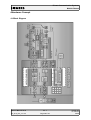
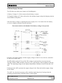
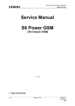
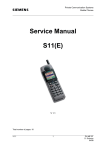
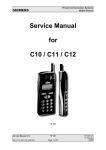
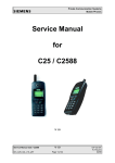
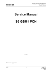
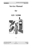
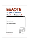
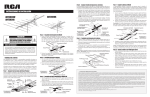
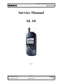
Private Communication Systems Mobile Phones Service Manual SL 10 V 1.1 Service Manual SL10 V1.1 Sm_sl10_lvl2_v11.doc Page 1 of 23 PN MP ST R. Fleuren 05/98 Private Communication Systems Mobile Phones 1Table of Contents 1 TABLE OF CONTENTS....................................................................................................................................2 1 TECHNICAL DATA...........................................................................................................................................3 2 GENERAL INFORMATION.............................................................................................................................4 3 MECHANICAL CONCEPT...............................................................................................................................4 3.1 MECHANICAL DRAWING OF THE SL10 .........................................................................................................................................................................5 3.2 DISASSEMBLING THE SL10...............................................................................................................................6 3.2.1 Necessary tools........................................................................................................................................6 3.2.2 Disassembling the Mobile.......................................................................................................................6 3.2.3 Disassembling the Slide ...........................................................................................................................................................................7 3.2.4 Disassembling the Top Part of the Base.................................................................................................8 3.2.5 Disassembling the Bottom Part of the Base .........................................................................................................................................................................10 3.3 ASSEMBLING THE SL10.................................................................................................................................10 3.3.1 Assembling the Bottom Part of the Base .........................................................................................................................................................................10 3.3.2 Assembling the Top Part of the Base....................................................................................................11 3.3.3 Assembling the Slide .........................................................................................................................................................................11 3.3.4 Assembling the Mobile..........................................................................................................................12 3.4 HANDSET DATECODES...................................................................................................................................13 4 HARDWARE CONCEPT .................................................................................................................................................................................15 4.1 BLOCK DIAGRAM..........................................................................................................................................15 4.2 HARDWARE DESCRIPTION...............................................................................................................................16 4.3 POWER SUPPLY CONCEPT...............................................................................................................................17 4.4 LIMITS OF VOLTAGE AND CURRENT .................................................................................................................18 5 BATTERY..........................................................................................................................................................19 5.1 SPECIFICATION..............................................................................................................................................19 5.2 SHORT CIRCUIT PROTECTION...........................................................................................................................19 5.3 DEEP DISCHARGE.........................................................................................................................................19 5.4 BATTERY DATECODES....................................................................................................................................20 6 SOFTWARE PROGRAMMING.....................................................................................................................21 6.1 DESCRIPTION OF SOFTWARE BOOTING .......................................................................................................................................................................21 6.2 LANGUAGE GROUPS......................................................................................................................................22 7 UNBLOCKING .................................................................................................................................................22 7.1 SIEMENS HOTLINE.........................................................................................................................................22 7.2 INTERNET SOLUTION.......................................................................................................................................23 Service Manual SL10 V1.1 Sm_sl10_lvl2_v11.doc Page 2 of 23 PN MP ST R. Fleuren 05/98 Private Communication Systems Mobile Phones 1Technical Data Length: 129 mm Width: 50 mm Thickness: 26 mm Volume: 121 cm³ Weight: 138 grams Performance: GSM class 4 (2 Watt) Frequency Range: Tx 890-915 MHz Rx 935-960 MHz Power supply: Lithium Ion battery (3,6V/550mAh) Standby time: Up to 35 hours Talk time: Up to 3 hours. Charging time: approx. 1 hour Display: LCD high-resolution colour graphic display SIM Card Type: Plug-In, 3V or 5V Antenna: Non-retractable, Lambda/2 helix type Service Manual SL10 V1.1 Sm_sl10_lvl2_v11.doc Page 3 of 23 PN MP ST R. Fleuren 05/98 Private Communication Systems Mobile Phones 2General Information The SL10 is the first Siemens mobile GSM telephone using the new MCM chipset technology. It further consists of a slide mechanism, the so called ProSLIDE system, which e.g. supports ON-Hook and OFF-hook function. As in S10active, the SL10 also features a real time clock. Additionally it is equipped with an infrared interface e.g. for data transmission. TM 3Mechanical Concept Note: All part numbers refer to mechanical drawing in section 4.1! These numbers are not valid for ordering spare parts. For appropriate ordering numbers please refer to the official spare part list. If you have questions regarding spare parts, please contact your service manager. The SL10 consists of two major parts: The slide unit and the base unit. User interface compared to other Siemens mobiles is not realised by just one MMI board containing all necessary components, but is separated into a MMI board (1010) inside the slide unit which carries display and a part of the keypad (1250), and a second keypad (1240) inside of the base unit. Microphone (1200) also is located in the base unit. The connection between MMI board and RF&Control board is not established by a normal connector with plug-in contacts or an interconnector (e.g. like in S6), but by a flexible cable. The same kind of cable is used to connect the keypad (1240) and microphone (1200) inside of the base unit to the RF&Control board (1000). The one end of these cables is soldered to the appropriate board, the other end is plugged into a ZIF-connector (ZIF= Zero Insertion Force). Attention: The flexible cables are very sensitive to any kind of mechanical mistreatment. Please be careful not to damage them during the repair process of the telephone! Various kinds of failures can come up even if these cables are only bended. The shielding concept is similar to the one of S6. The upper case (1040) of the base unit is coated with a conductive material and conductive rubber. This establishes the shielding of the one side of RF&Control module (1010). On the opposite side of this board there is a shielding screen (1160) above the relevant area, which is fixed by four screws (1280). The antenna (1230) is directly screwed into the lower case (1050) of the base unit. The keypad (1240), the loudspeaker (1220), dust protection frame (1070) and MMI board (1010) are mounted into the upper case (1020) of the slide unit. Please make sure while assembling the slide unit that the metal contacts of the dust protection frame (1070) are properly bent up when mounting. When turning in the screws (1270, 1280, 1290) make sure that the right torque is used (1280, 1290: (0,08+0,02)Nm; 1270: (0.2+0,05)Nm). Service Manual SL10 V1.1 Sm_sl10_lvl2_v11.doc Page 4 of 23 PN MP ST R. Fleuren 05/98 Private Communication Systems Mobile Phones 3.1Mechanical drawing of the SL10 Service Manual SL10 V1.1 Sm_sl10_lvl2_v11.doc Page 5 of 23 PN MP ST R. Fleuren 05/98 Private Communication Systems Mobile Phones 3.2Disassembling the SL10 Caution! Inside the telephone there are three flexible cables, which are very sensitive to any kind of mechanical damage. Please be careful during all the disassembling process not to damage them e.g. by bending or snapping. 3.2.1Necessary tools For disassembling the SL10 the following tools are mandatory: - Metal blade - Catch lever - Screwdriver Torx 6 - Tweezer 3.2.2Disassembling the Mobile 1. Remove battery and SIM-Card 2. Unscrew antenna. 1. Remove the two countersunk-head screws at the lower end of the telephone (below vent plug) and inside the battery department. 2. Move slide all the way to the open position. 3. Undo the slide stop by inserting the metal strip on the left side between the slide and the base. 1. Turn the mobile over and push the metal strip through until it is visible above the keypad. Service Manual SL10 V1.1 Sm_sl10_lvl2_v11.doc Page 6 of 23 PN MP ST R. Fleuren 05/98 Private Communication Systems Mobile Phones 1. Then use your thumb to press the slide up to separate it from the base. The second stop which is mounted at the bottom of the slide has to be released at the same time. To do so, push the bottom of slide upwards and continue pushing the slide with the thumb. The metal blade can be removed when the stop on the top of base is visible completely. 1. Remove spring and stop from top of base. Attention: Flexible cable is very sensitive to any kind of mechanical damage (e.g. bending, snapping). 1. Use the catch lever to unlock the six catches (see figures below) in order to separate the top part of the base from the bottom part of the base. 1. Now detach the flexible cable from the plug on the control module by undoing the retaining clip on the plug and then pulling the cable out. a) b) c) 1. Now you have separated the three major parts of the telephone a) Slide, b) Top of base, c) Bottom of base 6 5 4 3 2 1 Service Manual SL10 V1.1 Sm_sl10_lvl2_v11.doc Page 7 of 23 PN MP ST R. Fleuren 05/98 Private Communication Systems Mobile Phones 3.2.3Disassembling the Slide 1. Unscrew the countersunk-head screw (A) 2. Next, release the lower catch (B) 3. Then release the six lateral catches (1-6 ) 1. After releasing the catches, remove the bottom part of the slide. 2. Now remove the MMI board from the bottom part of the slide by raising the board (1.) and pushing it toward the keypad (2.). Attention: Do not crease or damage the flexible cable on the lower side of the MMI. 2. 1. 1. Finally, remove the dust protection frame, the keypad mat and the loudspeaker from the top part of the slide. You now have disassembled the slide completely. 3.2.4Disassembling the Top Part of the Base 1. First remove the microphone holder and the flexible microphone cable attached to it from the microphone housing. 6 3 5 2 4 1 A B 1. Then detach the flexible keypad cable from the ZIF-plug (ZIF=Zero Insertion Force). To do so, please first open the retaining clip and pull out the cable afterwards. 2. Remove the ringer gasket. 3. Now remove the four torx flat-head screws on the screen lid and the two torx countersunkhead screws on the side of the microphone. Service Manual SL10 V1.1 Sm_sl10_lvl2_v11.doc Page 8 of 23 PN MP ST R. Fleuren 05/98 Private Communication Systems Mobile Phones 1. Now remove the control module and the screen lid. 2. Finally, remove the microphone. Now you completed disassembling the Top of base. Service Manual SL10 V1.1 Sm_sl10_lvl2_v11.doc Page 9 of 23 PN MP ST R. Fleuren 05/98 Private Communication Systems Mobile Phones 3.2.5Disassembling the Bottom Part of the Base 1. First remove the battery baseplate. 2. Then remove the battery contact strip. 3. Finally, remove the charge contacts. 3.3Assembling the SL10 Caution! Inside the telephone there are three flexible cables, which are very sensitive to any kind of mechanical damage. Please be careful during all the assembling process not to damage them e.g. by bending or snapping. 3.3.1Assembling the Bottom Part of the Base Insert the charge contacts, the battery contact strip and the battery baseplate. Make sure that you insert the baseplate in the right way, because otherwise you will have to reopen the phone again (See figures below). o.k. Not o.k. Service Manual SL10 V1.1 Sm_sl10_lvl2_v11.doc Page 10 of 23 PN MP ST R. Fleuren 05/98 Private Communication Systems Mobile Phones 3.3.2Assembling the Top Part of the Base 1. First insert the microphone into the top part of the base. 2. Now insert the control module, mount the screen lid and screw in the six screws. 3. Mount the ringer gasket. 4. Connect the flexible keypad cable to the plug on the control module and press the retaining clip down. 5. Finally, mount the flexible microphone cable onto the microphone housing 3.3.3Assembling the Slide 1. First insert the loudspeaker and the keypad mat into the device. 1. Insert the dust protection frame into the top part of the slide. Caution! - The copper side must point toward the housing. - The strap must be bent in a way that it lies on the keypad mat (see figure beside). 1. Thread the flexible cable of the MMI into the lower part of the slide, mount the MMI board and lock it in place. Pull the flexible cable carefully out all the way. Caution! Do not crease or damage the flexible cable e.g. like shown in the figure beside. 1. With its top edge leading, insert the lower part of the slide into the top part of the slide, letting the catches snap into place one after the other from top to bottom. 2. Finally, screw in the torx countersunk-head screw. Service Manual SL10 V1.1 Sm_sl10_lvl2_v11.doc Page 11 of 23 PN MP ST R. Fleuren 05/98 Private Communication Systems Mobile Phones 3.3.4Assembling the Mobile 1. First insert the slide stop and the spring into the top of the base. The spring has to be inserted into the gap which is closer to the upper end of the telephone (where the infrared interface is located) 1. Now mount the slide on the guide rails in the top part of the base. Caution! Applying too much pressure will damage the plastic parts, especially the upper part of the slide is very sensitive. 1. Close the slide. 1. Connect the flexible cable to the plug on the control module and affix the retaining clip to the plug. 1. Insert the interconnected slide/top of the base into the bottom of the base Caution! First secure the catch to the top edge of the housing so that the flexible cable is not damaged. Afterwards fix the catches (see figures below). 2. Screw the torx countersunk screws into the battery compartment and into the housing. Cover the housing screw with the plastic cap. 3. Finally, screw in the antenna and insert the SIM card rack bearing the SIM card. Service Manual SL10 V1.1 Sm_sl10_lvl2_v11.doc Page 12 of 23 PN MP ST R. Fleuren 05/98 Private Communication Systems Mobile Phones 3.4Handset Datecodes Siemens is using the industrial standard DIN EN 60062 to indicate the production / service dates. The code is printed on the IMEI sticker located in the battery compartment. -> YY = Datecode The first character of the datecode indicates the year of production: F H J K = 1995 = 1996 = 1997 = 1998 The second character indicates the month of production: 1-9 = january to september O = october N = november D = december Service Manual SL10 V1.1 Sm_sl10_lvl2_v11.doc Page 13 of 23 PN MP ST R. Fleuren 05/98 Private Communication Systems Mobile Phones Example: „JO“ means that the set was produced in october of 1997. Service Manual SL10 V1.1 Sm_sl10_lvl2_v11.doc Page 14 of 23 PN MP ST R. Fleuren 05/98 Private Communication Systems Mobile Phones 4Hardware Concept 4.1Block Diagram Service Manual SL10 V1.1 Sm_sl10_lvl2_v11.doc Page 15 of 23 PN MP ST R. Fleuren 05/98 Private Communication Systems Mobile Phones 4.2Hardware Description The handset consists of five major integrated circuits. Some of them - beside others - are integrated into just one single IC, the so called Multi Chip Module (MCM). 1) HiGOLD PMB 2800 (inside MCM) This IC is a combination of microprocessor and signalprocessor. The microprocessor is responsible for controlling the keyboard, SIM-Card, EEPROM, Flash and RAM. Furthermore it controls the power up/power down of the RF module and sets the amplification of the PA. The signal processor is responsible for processing the Rx I/Q signals (filtering, equalizing, speech and channel decoding). Furthermore it does the speech and channel encoding and the GSMK modulation of the Tx I/Q signals. 3) GAIM PMB 2905 (inside MCM) The GAIM provides the interface between the analogue signals (I/Q, voiceband, PA-control) and its digital representation. 4) Receiver Circuit (PMB 2409) This circuit provides the following main functionalities: x Low Noise Amplifier (LNA) with a fixed amplification of +20dB to amplify the input RF signal. Mixer to mix down the RF signal to the Intermediate Frequency (IF) Programmable IF amplifier with a dynamic range of 60dB ( -10dB to +50dB in X steps of 2dB) è Mixer to mix down the IF signal to the baseband, generating and inphase (I) and a quadrature (Q) signal. ¸ Offset compensation for the I/Q signals. 5) Transmitter Circuit PMB 2240/45 This circuit provides the IF synthesizer, the I/Q modulator, prescalers to regulate the RF synthesizer and a buffer stage to feed the PA. Service Manual SL10 V1.1 Sm_sl10_lvl2_v11.doc Page 16 of 23 PN MP ST R. Fleuren 05/98 Private Communication Systems Mobile Phones 4.3Power Supply Concept The SL10 has two main power inputs (see blockdiagram): 1) Battery Voltage (3.6 Volts) connected at the battery contacts 2) Charging Voltage (6.5 Volts) delivered by the desktop charger (using the charging contacts at the bottom of the phone) Since the battery voltage is supplying the power supply asic, it is a must to have the battery (or service adapter) inserted to operate the phone. You cannot switch on the handset if the battery voltage is not present. From the 3.6V battery voltage, all other supply voltages of the SL10 are derived, controlled by the power supply ASIC. The RF module needs 6.0V for its PA: This voltage is generated by a step-up converter. The logic module, MMI and IrDA circuit use 2.8V, generated by a linear regulator inside the ASIC. The operating voltage for the display illumination (100Vpk) is derived from this 2.8V also. Furthermore the ASIC generates the supply voltage for the Chip-card and the supply voltage for the Flash. The ASIC also checks the presence of the watchdog signal from the µP and provides the switching on-functionality (ON/OFF button or timer signal). Service Manual SL10 V1.1 Sm_sl10_lvl2_v11.doc Page 17 of 23 PN MP ST R. Fleuren 05/98 Private Communication Systems Mobile Phones The 2.8V power supply of TCXO, Receiver and Modulator is derived directly from the battery voltage by a separate linear regulator. During testing ist is advisable to use the service adapter, connected to a power supply delivering +4V, max 3A. Make sure that you connect the service adapter with the right polarity, the red plug to +4V and the blue plug to ground. CAUTION! If you use a voltage higher than +7V, or with wrong polarity, the phone can be destroyed! 4.4Limits of Voltage and Current a) Battery Voltage: If the battery voltages rises above 6.2 Volts, the phone will switch off and it cannot be switched on again before the voltage is lower than 6.2 Volts. If the battery voltage rises above 7 Volts the phone can be destroyed. b) Charging Current: The charging current must not rise above 1 A or the phone (fuse) will be inoperable. Be careful with foreign accessories or chargers! Make sure that the charging current is limited to a value below 1A! Service Manual SL10 V1.1 Sm_sl10_lvl2_v11.doc Page 18 of 23 PN MP ST R. Fleuren 05/98 Private Communication Systems Mobile Phones 5Battery 5.1Specification The SL10 battery is a Lithium-Ion type with a voltage of 3.6 Volts and a capacity of 550mAh. The connections BATT+ and GND are used to supply the mobile, while RCODE is used to detect the battery technology. BATT_TEMP is used to measure the battery temperature. BATT+ RCODE BATT_TEMP GND Charging the battery can be impossible, if the temperature of the battery cells is too high (e.g. in car use during summer) or too low. This is to prevent the battery from being damaged during fast charge process. To enable the charging process again, the battery only needs to cool down/warm up. A replacement of battery is not necessary. 5.2Short Circuit Protection The battery is short-circuit protected by an electronic fuse. The resetting of the fuse can be done by the following procedures: Plug the battery into the desktop charger. H or ˆ Apply +5 Volts between the BATT+ and GND contacts (see drawing!) Caution! Limit the current to 10mA. 5.3Deep Discharge If the battery is deeply discharged it can be recharged by the following procedure: • Insert flat battery into handset and connect travel charger. The charging symbol will not be visible. Wait for appr. 1 hour and disconnect charger afterwards. • Remove battery and reinsert it. If you connect the travel charger now, the charging symbol must be visible on the handset display. Service Manual SL10 V1.1 Sm_sl10_lvl2_v11.doc Page 19 of 23 PN MP ST R. Fleuren 05/98 Private Communication Systems Mobile Phones 5.4Battery Datecodes The datecode printed on the battery will give you the following information: Example: TOS 8 G9 VA 1 TOS 8 G9 VA 1 = Battery cells supplied by Toshiba = Revision level = Datecode (see below) = Varta (battery manufacturer) = Place of manufacturing (1=Germany ,2= Novibor, Czech Republic) Datecode: Character 1: Year of production (J= 1997, K= 1998) Character 2: Month of production (1-9 means January to September; O=October; N=November ; D=December) Example: TOS 8 K4 VA 1 This battery was produced in april of 1998! Service Manual SL10 V1.1 Sm_sl10_lvl2_v11.doc Page 20 of 23 PN MP ST R. Fleuren 05/98 Private Communication Systems Mobile Phones 6Software programming The software of the SL10 handset is programmed directly from a PC using a bootadapter as an interface beetween serial port of the PC and the mobile. Because the SL10 does not carry an external connector (e.g. like S6) an additional service adapter is needed. This service adapter replaces the battery of the phone and contacts three pads inside the battery department of the telephone. Via this contacts and the bootadapter a serial communication is established between the SL10 and the PC. 6.1Description of software booting p Connect COM-port of PC to the bootadapter using the enclosed RS232 cable. Afterwards plug in AC-Adapter: If H connected correctly the „Power“ lamp will be active. AC-Adapter Service Adapter RS-232 cable ¸ Switch off the SL10 handset and remove the battery. Insert the service adapter instead of the battery, connect it to the boot adapter and plug in the ACadapter of the service adapter. Bootadapter Connection Cable AC-Adapter ° Copy bootsoftware to the PC and follow the instructions in the file „readme.txt“. Ordering number of Bootadapter: L24857-F1006-A30 The bootadapter comes complete with AC-Adapter, RS-232 and handset connection cable. Ordering number of Service Adapter: L36880-N1601-A130 The service adapter is shipped incl. AC-Adapter Service Manual SL10 V1.1 Sm_sl10_lvl2_v11.doc Page 21 of 23 PN MP ST R. Fleuren 05/98 Private Communication Systems Mobile Phones 6.2Language Groups There are different languages groups of the same mobile software version available. Each of them contains of several menue languages. The actual supported languages are: Arabic Danish French Hungarian Norwegian Spanish Catalan English German Italian Portuguese Swedish Chinese Finnish Greek Netherlands Russian Turkish Attention: This information is subject to change! For the latest update, appropriate language group for your country and ordering numbers of the different language groups please contact your Siemens service coordinator. 7Unblocking If the phone is disabled due to a wrong entry of the phonecode (not PIN1, PIN2, network code or service provider code!) it can only be resetted by entering the right unblocking code. This unblocking code is derived from the IMEI number of the mobile and can only be calculated in two different ways: 7.1Siemens Hotline You can retreive the code from our hotline personell in Germany. If you need unblocking codes just send a fax with the IMEI numbers to: Siemens AG PN MP SH World Service Center Bocholt, Germany Fax: +49 2871 91 3007 Please use the appropriate form provided by your Siemens service coordinator! Service Manual SL10 V1.1 Sm_sl10_lvl2_v11.doc Page 22 of 23 PN MP ST R. Fleuren 05/98 Private Communication Systems Mobile Phones 7.2Internet solution As an alternative to the a.m. procedure, since november 1997 an internet solution is offered to the LSO. It is a password protected internet homepage where you can enter the IMEI number of the affected handset. The page will then present Master Phone Codes, Master Network Codes and Master Service Provider Codes (if applicable to the relevant telephone). If you do not have access to this tool up to now, please contact your Siemens service manager for details. Service Manual SL10 V1.1 Sm_sl10_lvl2_v11.doc Page 23 of 23 PN MP ST R. Fleuren 05/98