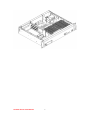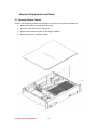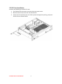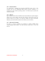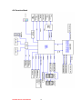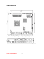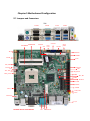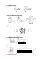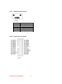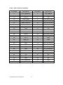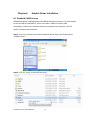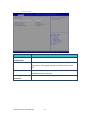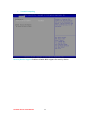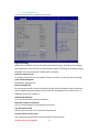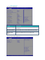
1
IV7T-RK2U IV7W-RK2U 2U Rack Mount Server PC Intel® Core™i7-3520M Processor, 2.9 GHz ,up to 3.6GHz/4MB Cache /35W VGA, Dual LAN, 4xUSB 3.0, 2xUSB 2.0, 2xPCI Slot EC 61850-3, IEC60068-64, IEC 60068-2-2 Certificated USER MANUAL Version 1.1 WinMate Communication INC. FCC Statement This device complies with part 15 FCC rules. Operation is subject to the following two conditions: This device may not cause harmful interference. This device must accept any interference received including interference that may cause undesired operation. This equipment has been tested and found to comply with the limits for a class "a" digital device, pursuant to part 15 of the FCC rules. These limits are designed to provide reasonable protection against harmful interference when the equipment is operated in a commercial environment. This equipment generates, uses, and can radiate radio frequency energy and, if not installed and used in accordance with the instruction manual, may cause harmful interference to radio communications. Operation of this equipment in a residential area is likely to cause harmful interference in which case the user will be required to correct the interference at him own expense. Safety Precautions Warning! Always completely disconnect the power cord from your chassis whenever you work with the hardware. Do not make connections while the power is on. Sensitive electronic components can be damaged by sudden power surges. Only experienced electronic personnel should open the PC chassis. Caution! Always ground yourself to remove any static charge before touching the CPU card. Modern electronic devices are very sensitive to static electric charges. As a safety precaution, use a grounding wrist strap at all times. Place all electronic components in a static-dissipative surface or static-shielded bag when they are not in the chassis. 2U Rack Series User Manual II Copyright Notice ALL RIGHTS RESERVED. No part of this document may be reproduced, copied, translated, or transmitted in any form or by any means, electronic or mechanical, for any purpose, without the prior written permission of the original manufacturer. Trademark Acknowledgement Brand and product names are trademarks or registered trademarks of their respective owners. Disclaimer We. reserves the right to make changes, without notice, to any product, including circuits and/or software described or contained in this manual in order to improve design and/or performance. We assume no responsibility or liability for the use of the described product(s), conveys no license or title under any patent, copyright, or masks work rights to these products, and makes no representations or warranties that these products are free from patent, copyright, or mask work right infringement, unless otherwise specified. Applications that are described in this manual are for illustration purposes only. We Communication Inc. makes no representation or warranty that such application will be suitable for the specified use without further testing or modification. Warranty We warrant that each of its products will be free from material and workmanship defects for a period of one year from the invoice date. If the customer discovers a defect, We will, at its option, repair or replace the defective product at no charge to the customer, provided it is returned during the warranty period of one year, with transportation charges prepaid. The returned product must be properly packaged in its original packaging to obtain warranty service. If the serial number and the product shipping data differ by over 30 days, the in-warranty service will be made according to the shipping date. In the serial numbers the third and fourth two digits give the year of manufacture, and the fifth digit means the month (e. g., with A for October, B for November and C for December). For example, the serial number 1W07Axxxxxxxx means October of year 2007. 2U Rack Series User Manual III Customer Service We provide service guide for any problem as follow steps: Please contact with your distributor, sales representative, or our customer service center for technical support if you need additional assistance. You may have the following information ready before you call: Product serial number Peripheral attachments Software (OS, version, application software, etc.) Description of complete problem The exact wording of any error messages In addition, free technical support is available from our engineers every business day. We are always ready to give advice on application requirements or specific information on the installation and operation of any of our products. Please do not hesitate to call or e-mail us. 2U Rack Series User Manual IV Safety and Warranty 1. 2. 3. 4. 5. 6. 7. 8. 9. 10. 11. 12. 13. 14. Please read these safety instructions carefully. Please keep this user's manual for later reference. Please disconnect this equipment from any AC outlet before cleaning. Do not use liquid or spray detergents for cleaning. Use a damp cloth. For pluggable equipment, the power outlet must be installed near the equipment and must be easily accessible. Keep this equipment away from humidity. Put this equipment on a reliable surface during installation. Dropping it or letting it fall could cause damage. The openings on the enclosure are for air convection. Protect the equipment from overheating. DO NOT COVER THE OPENINGS. Make sure the voltage of the power source is correct before connecting the equipment to the power outlet. Position the power cord so that people cannot step on it. Do not place anything over the power cord. All cautions and warnings on the equipment should be noted. If the equipment is not used for a long time, disconnect it from the power source to avoid damage by transient over-voltage. Never pour any liquid into an opening. This could cause fire or electrical shock. Never open the equipment. For safety reasons, only qualified service personnel should open the equipment. If any of the following situations arises, get the equipment checked by service personnel: A. The power cord or plug is damaged. B. Liquid has penetrated into the equipment. C. The equipment has been exposed to moisture. D. The equipment does not work well, or you cannot get it to work according to the user’s manual. E. The equipment has been dropped and damaged. F. The equipment has obvious signs of breakage. 2U Rack Series User Manual V Revision History Version Date 1.0 2014.11.11 1.1 2015.02.16 2U Rack Series User Manual Note Initial Draft Add Watch Dog function setting description. VI Author Henry Lee Patrick Hsien Contents CHAPTER 1 OVERVIEW ..........................................................................1 1.1 INTRODUCTION ................................................................................... 1 1.2 FEATURES .......................................................................................... 1 1.3 HARDWARE SPECIFICATIONS .................................................................. 2 CHASSIS DIMENSION ........................................................................................ 4 CHAPTER 2 HARDWARE FUNCTIONS ....................................................7 2.1 2.2 2.3 2.4 SYSTEM POWER/RESET SWITCHES .......................................................... 7 SYSTEM LED INDICATORS...................................................................... 7 SYSTEM POWER INPUT ......................................................................... 7 PS/2 KEYBOARD AND PS/2 MOUSE CONNECTORS ..................................... 8 2.5 2.6 2.7 2.8 2.9 SERIAL COM PORTS ............................................................................ 8 ETHERNET INTERFACE (LAN) ................................................................. 8 USB PORTS ....................................................................................... 8 VGA PORT ........................................................................................ 8 AUDIO JACK (PIN-HEADER).................................................................... 8 CHAPTER 3 3.1 3.2 3.3 3.4 CHAPTER 4 EQUIPMENT INSTALLATION .............................................10 OPENING SYSTEM CHASSIS .................................................................. 10 PCI CARD INSTALLATION ..................................................................... 11 MEMORY MODULE (SODIMM) INSTALLATION ...................................... 12 REMOVING HARDDRIVE ...................................................................... 13 MOTHERBOARD INFORMATION ......................................15 4.1 4.2 4.3 4.4 FEATURES ........................................................................................ 15 MOTHERBOARD I/O .......................................................................... 15 MOTHERBOARD SPECIFICATIONS .......................................................... 17 FUNCTION BLOCK .............................................................................. 18 4.5 BOARD DIMENSIONS .......................................................................... 19 CHAPTER 5 5.1 5.2 5.3 CHAPTER 6 MOTHERBOARD CONFIGURATION ..................................21 JUMPERS AND CONNECTORS ................................................................ 21 JUMPER SETTING............................................................................... 22 CONNECTORS AND PIN ASSIGNMENT..................................................... 25 GRAPHIC DRIVER INSTALLATION .....................................35 2U Rack Series User Manual VII 6.1 STANDARD CMOS FEATURE ................................................................ 35 6.2 PANEL RESOLUTION SETTING ............................................................... 39 CHAPTER 7 7.1 CHAPTER 8 8.1 CHAPTER 9 9.1 9.2 CHIPSET DRIVER INSTALLATION .......................................42 STANDARD CMOS FEATURES............................................................... 42 ETHERNET DRIVER INSTALLATION ...................................46 INSTALLATION OF ETHERNET DRIVER ..................................................... 46 AUDIO DRIVER INSTALLATION .........................................50 INTRODUCTION ................................................................................. 50 INSTALLATION OF AUDIO DRIVER .......................................................... 50 CHAPTER 10 COM PORT DRIVER INSTALLATION ..................................53 CHAPTER 11 AMI BIOS SETUP ...............................................................57 11.1 11.2 11.3 11.4 11.5 11.6 STARTING SETUP ............................................................................... 57 ADVANCED SETTING........................................................................... 59 CHIPSET SETTING .............................................................................. 84 BOOT .............................................................................................. 93 SECURITY ......................................................................................... 96 SAVE & EXIT..................................................................................... 97 CHAPTER 12 WATCHDOG FUNCTION SETTINGS ...................................99 12.1 12.2 WHAT IS WATCHDOG TIMER................................................................ 99 DEMO AND CODING REFERENCE ......................................................... 100 CHAPTER 13 SERVICES/ UPDATES .......................................................104 13.1 13.2 IV70 OFFICIAL WEBSITE ................................................................... 104 COMPANY INFORMATION .................................................................. 104 2U Rack Series User Manual VIII CHAPTER Overview 1 This chapter includes IV7T-RK2U/IV7W-RK2U Embedded Server PC overview information. Sections include: Introduction Feature Packing List Hardware Specification Chassis Dimensions 2U Rack Series User Manual 1 Chapter 1 Overview 1.1 Introduction IV7T-RK2U/IV7W-RK2U is an embedded server PC that excels in wide array of substation automation roles. Featuring high performance Intel Core i7 Processor in a 2U Rack mount reliable fan-less design, IV7TRK2U/IV7W-RK2U provides the processing power to handle demanding industrial tasks without consuming a lot of power. The server PC operates on Windows Embedded Standard 7 – WS7E or Windows Server 2008 R2 for reliable field application. In addition, IV7T-RK2U /IV7W-RK2U offer a wide array of I/Os, including one VGA port, two Gigabit Ethernet ports, two RS232 serial ports, one RS232/422/485 serial port (jumper configurable), four USB 3.0 ports, and two USB 2.0 ports, providing connectivity for diverse applications. IV7T-RK2U/IV7W-RK2U has been certificated with IEC 61850-3, which is the international hardware standard of communication network and system in power substations. This standard facilitates the management to large number of devices and enables the communications between the various devices. In addition, the server PC operates reliably in wide temperature range of -10°C to 60°C/ -40°C to 70°C, offering an optimal solution for applications subjected to harsh environmental requirements. 1.2 Features IEC 61850-3, IEC60068-2-64, IEC 60068-2-2 certificated. Intel® Core™ i7-3520M Processor , 2.9 GHz up to 3.6GHz/4MB Cache/35W Max 16 GB DDR3 1333/1600(Depend on Operating System, Default 4GB) 3 x RS232 Serial Ports(1x RS422/485 by Jumper), Expansion PCI card with 4 x RS232 (Optional) 2x Giga LAN, 4x USB 3.0, 2x USB 2.0, Line in, Line out, Micro in, PS/2 for Keyboard & Mouse Fan-less, High efficiency thermal design w/ sealed construction Supports 2 x 2.5" HDD(1 x SATAII, 1 x SATAIII) or 2.5” SSD Support GPS function(Optional) Mounting in Standard 19"/2U Equipment Rack Operating Temperature: IV7T-RK2U(-10°C to 60°C) IV7W-RK2U(-40°C to 70°C) 2U Rack Series User Manual 1 1.3 Hardware Specifications System Specification Processor Socket rPGA988B Processor Intel® Core™ i7-3520M Processor, 2.9 GHz up to 3.6GHz/4MB Cache/35W BIOS AMI System BIOS System Chipset Intel® 7 series Chipset HM76 System Memory Two DDR3 1333/1600MHz SO-DIMM supported (system max. 16GB) Ethernet Controller Broadcom BCM57780 GbE controller Serial 2 x RS-232 1 x RS-232/422/485(select by jumper) SDD Interface SATAIII mSATA SSD Max.512GB GPS(Optional) U-blox GPS module I/O Connectors Front Side I/O 1 x Power On/Off 1 x Reset Button 2 x USB 2.0 1 x Front-accessible 2.5” Drive Bay (Support 2 x 2.5” HDD or SSD) Back Side I/O 1 x 3 Pin Acrylic Protect Connector for AC/DC Input 2 x PS/2 for Keyboard & Mouse 3 x RS232(1x RS422/485 by Jumper) 2 x RJ-45 GigaLAN 4 x USB3.0 1 x GPS ANT SMA port (Optional) 1 x Mic in, Line out, Line in Jack Mechanical and Environment Dimensions (L x W) 482.6mm x 88mm x 356mm Construction Electroplated steel Power Input AC/ DC 100V~240V Environment Specification Operating Temperature -10°C to 60°C(IV7T-RK2U) -40°C to 70°C(IV7W-RK2U) Operating Humidity 10% to 95% (non condensing) Certifications IEC 61850-3, IEC60068-2-64, IEC 60068-2-2 ,CE,FCC 2U Rack Series User Manual 2 Mounting 2U Rack Series User Manual 2U Rack mount 3 Chassis Dimension 2U Rack Series User Manual 4 2U Rack Series User Manual 5 CHAPTER Hardware Functions 2 This chapter includes IV7T-RK2U/IV7W-RK2U Embedded Server PC Hardware I/O Information. Sections include: System Power/Reset Switches System LED Indicators System Power Input PS/2 Keyboard and PS/2 Mouse Connectors Serial COM Ports Ethernet Interface (LAN) USB Ports VGA Port Audio Jack (Pin-header) 2U Rack Series User Manual 6 Chapter 2 Hardware Functions 2.1 System Power/Reset Switches The system power switch and the reset switch are both located on the front panel. 2.2 System LED Indicators The system status are indicated on the front panel with the LED indicators: Definition of System Indicator Item LED Identifier Status Description 1 POWER On System Power is On Off System Power is Off On Hard disk is being accessed Off Hard disk is idling On Network activity occurred on LAN1 Ethernet port Off Network is idling on LAN1 Ethernet port On Network activity occurred on LAN2Ethernet port Off Network is idling on LAN2Ethernet port 2 3 4 HDD LAN1 LAN2 2.3 System Power Input The IV7T-RK2U/IV7W-RK2U support AC/ DC power input to fulfill the need of field site. The power input is located on the rear panel, and has the following specification: Power Inout Voltage Range Power Rating Connector Type AC 100-240V 2A~1A, 47-63Hz 3Pin Screw Terminal DC 100-240V 2A~1A 3Pin Screw Terminal 2U Rack Series User Manual 7 2.4 PS/2 Keyboard and PS/2 Mouse Connectors The Motherboard provides two PS/2 interface. The PS/2 connector supports Keyboard and Mouse. In other cases, especially in embedded applications, a mouse is not used. Therefore, the BIOS standard setup menu allows you to select* “All, But Keyboard” under the “Halt On”. This allows no-keyboard operation in embedded system applications without the system halting under POST. 2.5 Serial COM Ports There are two RS-232 connectors, and one COM port that can support RS-232/422/485 through jumper settings. See the motherboard COM port section for detail jumper settings. 2.6 Ethernet Interface (LAN) Two Gigabit LAN ports reside in the rear of the device, and are fully compliant with the PCI 10/100/1000 Mbps, and are standard RJ-45 jacks. 2.7 USB Ports There are four USB 3.0 ports in the rear side of the server PC, and two USB 2.0 ports in the front. The USB ports support hot plug-in. 2.8 VGA Port The VGA connector is a standard 15-pin D-SUB connector, and can be connected to an external CRT/LCD monitor. 2.9 Audio Jack (Pin-header) The audio jack supports Audio 5.1 channel, and digital audio output. The audio interface includes Mic-in, line-in, and line-out. 2U Rack Series User Manual 8 CHAPTER Equipment Installation 3 This chapter includes IV7T-RK2U/IV7W-RK2U Embedded Server PC equipment installation information. Sections include: PCI Card Installation Memory Module (SODIMM) Installation 2U Rack Series User Manual 9 Chapter 3 Equipment Installation 3.1 Opening System Chassis Perform the following to open the equipment chassis for equipment installation 1. Remove all power and signal connections. 2. Place the unit with the top facing up. 3. Remove the screens shown on the diagram below. 4. Remove the cover as shown below. 2U Rack Series User Manual 10 3.2 PCI Card Installation Perform the following to install PCI Card: 1. First follow the instruction to remove the top system cover. 2. Remove the PCI slot covers for the desired slot. 3. Insert the PCI card from the rear of the system through the opening, and push into the slot as shown below. 2U Rack Series User Manual 11 3.3 Memory Module (SODIMM) Installation The IV70 Motherboard provides two 204-pin SODIMM slot. The socket supports up to 16GB DDR3 1333/1600 SDRAM. When installing the Memory device, please follow the steps below: 1. First follow the instruction to remove the top system cover 2. Locate the SODIMM slot on the motherboard. 3. Firmly insert the SODIMM at an angle into its slot. Align the SODIMM on the slot such that the notch on the SODIMM matches the break on the slot. 4. Press downwards on SODIMM until the retaining clips at both ends fully snap back in place and the SODIMM is properly seated. 2U Rack Series User Manual 12 3.4 Removing Harddrive The IV7T-RK2U/ IV7W-RK2U with a replaceable hard drive bay. Perform the following to remove hard drive from the bay: 1. Remove all power and signal connections. 2. Locate the removable hard drive bay in the front of the system. 3. Pull the hard drive mounting bracket out. 4. Remove the screws on the hard drive mounting bracket. 5. Remove the hard drive by lifting it out of the mounting bracket. 2U Rack Series User Manual 13 CHAPTER Motherboard Information 4 This chapter includes IV7T-RK2U/IV7W-RK2U Embedded Server PC motherboard information. Sections include: Features Motherboard Specifications Function Block Board Dimensions 2U Rack Series User Manual 14 Chapter 4 Motherboard Information 4.1 Features Mini-ITX Form Factor ( 170mm x 170mm) 3rd Generation Intel® CoreTM i7/i5 Processor System memory up to 16GB DDR3 1333/1600, 2 x SO-DIMM Rich I/O connectivity:1 x PCIEx16 slot, 2 x Mini-PCIE, 6 x COM, 4 x USB2.0, 4 x USB3.0, Dual GbE LAN Wide selection of storage devices: SATA HDD or SSD/SATAIII mSATA SSD, customers benefit from the flexibility of using the most suitable storage device for larger capacity Optimized integrated graphic solution: With Intel® Graphics Flexible, it supports versatile display options and 32-bit 3D graphics engine 4.2 Motherboard I/O 4.2.1 12V DC-IN The Motherboard allows plugging 12V DC-IN jack on the board without another power module converter under power consumption by Intel Socket G2 processor in HM76 with Intel® 7 series chipset. 4.2.2 PS/2 Keyboard and PS/2 Mouse The Motherboard provides two PS/2 interface. The PS/2 connector supports Keyboard and Mouse. In other cases, especially in embedded applications, a mouse is not used. Therefore, the BIOS standard setup menu allows you to select* “All, But Keyboard” under the “Halt On”. This allows no-keyboard operation in embedded system applications without the system halting under POST. 4.2.3 Serial COM ports Three RS-232 connectors build in the rear I/O. Fourth optional COM ports support RS-232. When an optional touch-screen is ordered with PPC, serial com port can connect to a serial or an optional touch-screen. One optional COM port supports RS232/422/485 choice through jumper setting. 4.2.4 Internal VGA The Motherboard has one VGA port that can be connected to an external CRT/ LCD monitor. Use VGA cable to connect to an external CRT / LCD monitor, and connect the power cable to the outlet. The VGA connector is a standard 15-pin D-SUB connector. 2U Rack Series User Manual 15 4.2.5 Ethernet interface The Motherboard is equipped with Broadcom BCM57780 chipset which is fully compliant with the PCI 10/100/1000 Mbps Ethernet protocol compatible. It is supported by major network operating systems. The Ethernet ports provide two standard RJ-45 jacks. 4.2.6 USB ports Eight USB devices (four with pin headers) may be connected to the system though an adapter cable. Various adapters may come with USB ports. USB usually connect the external system to the system. The USB ports support hot plug-in connection. Whatever, you should install the device driver before you use the device. 4.2.7 Audio Jack ( Pin-header) The Audio 5.1 channel capabilities are provided by a Realtek ALC886 chipset supporting digital audio outputs. The audio interface includes Mic-in,: line-in and line-out. 2U Rack Series User Manual 16 4.3 Motherboard Specifications CPU Type CPU Socket Chipset BIOS VGA DVI/HDMI LVDS LAN Memory Type Super I/O Keyboard/Mouse Sound USB Edge Connectors On Board Pin-Header Connectors Power Connector Expansion Slots Form Factor Dimensions Mechanical & environmental Intel® Core i7-3520M Processor, 2.9 GHz ,up to 3.6GHz/4MB Cache /35W Socket G2 (PGA988B) Intel® 7 series Chipset (HM76) AMI System BIOS Analog monitor resolution up to 2048 x 1536 @75Hz HDMI/DVI interface, support max. resolution 2560 x 1600 @60Hz Dual-channel 18/24-bit LVDS, supports max resolution 1920 x 1200 @60Hz Dual Broadcom BCM57780 PCIe GbE LAN controller Two DDR3 1333/1600 MHz SO-DIMM supported ( max. 16GB) Fintek F81865 2 x PS/2 Keyboard/Mouse connectors Realtek ALC886 HD codec (Line-in, Line out, Mic-in) 8 ports (4 x USB3.0 Connector, 4 x USB2.0 pin-header ) 1 x +12V DC-IN Jack 2 x PS/2 connector for keyboard/mouse 2 x DB9 for COM3 & COM4 1 x VGA out connector + 1 x DB9 for COM1 2 x Gigabit LAN RJ-45 + 1 x dual USB stack connector 1 x Audio Jack for Audio (Line-in, Line-Out, Mic-in) 1 x 10pins pin-header for Front Panel(2x5) 1 x 3pins pin-header for CPU Fan 1 x 3pins pin-header for System FAN 1 x 8pins pin-header for 5V/12V external power(2x4) 2 x 2pins pin-header for 5V external power (Red) 1 x 2pins pin-header for 12V external power (Yellow) 1 x 4pins ATX 12V connector 2 x 2pins Speaker 2 x 8pins pin-header for USB 5/6, 7/8(2x4) 3 x 10pins pin-header for COM2、COM5、COM6 (RS232)(2x5) 1 x 40pins DF13 Connector for LVDS 1 x 3pins digital panel backlight brightness controller 1 x 7pins digital panel backlight controller 1 x 10pins pin-header for DIO(2x5) 2 x SATA connector(1xSATAIII, 1xSATAII) 1 x HDMI connecter by FFC 1 x DVI connecter by FFC Input: 4-pin ATX 12V Power input 1 x PCIEx16, 1 x PCIEx4, 2 x Mini-PCIE, 1 x mSATA SSD Mini-ITX 170mm x 170mm Operating temperature: -10 deg. C to 60 deg. C (Standard), -40 deg. C to 70 deg. C (Optional) Operating Humidity: 30 ~ 90% Relative humidity, non-condensing Certification: CE, FCC, RoHS 2U Rack Series User Manual 17 4.4 Function Block 2U Rack Series User Manual 18 4.5 Board Dimensions 2U Rack Series User Manual 19 CHAPTER Motherboard Configuration 5 This chapter provides information on how to use the jumps and connectors on IV70 Motherboard. The Sections include: Jumpers and Connectors Setting the Jumpers 2U Rack Series User Manual 20 Chapter 5 Motherboard Configuration 5.1 Jumpers and Connectors TOP COM4 DC Jack PS/2 COM3 SODIMM2 SODIMM1 LAN1 COM1 VGA mSATA SIM LAN2 USB3.0 SATAIII HDD PWR JP10 SATAII Audio Jack front panel MiniPCIe HDMI LVDS DVI JP9, JP8 Inverter VR JP7, JP6 PCIEx16 JP5 NB_FAN1 CPU_FAN1 USB2 JP4, JP3 USB1 PCIEx4 COM2 COM5 COM6 LPT1 CN8,CN9 CN6 ATX12V J1,J2 2U Rack Series User Manual JP2 JP1 21MiniPCIe 5.2 Jumper Setting A pair of needle-nose pliers may be helpful when working with jumpers. If you have any doubts about the best hardware configuration for your application, contact your local distributor or sales representative before you make any changes. Generally, you simply need a standard cable to make most connections. The jumper setting diagram is as below. If a jumper shorts pin 1 and pin 2, the setting diagram is shown as the right one. Normal Clear CMOS 1 1 2 2 3 3 The following tables list the function of each of the board's jumpers. Label Function Note JP1 RS232 / RS422 / RS485 Selector 2x3 header , pitch 2.0mm JP2 RS232 / RS422 / RS485 Selector 3x4 header , pitch 2.0mm JP5 Clear CMOS 3x1 header , pitch 2.0mm JP6 VR/Software 3x1 header , pitch 2.0mm JP7 PWM/DA 3x1 header , pitch 2.0mm JP8 Back Light PWR 3x1 header , pitch 2.5mm JP9 PWM Level 3x1 header , pitch 2.0mm JP10 LVDS PWR Selector 2x3 header , pitch 2.5mm 2U Rack Series User Manual 22 5.2.1 JP1: RS232 / RS422 / RS485 Selector The jumper can be configured to operate COM1 in RS-232/422/485 mode. And the setting must be cooperated with JP2 settings. RS232 RS422/485 1 3 1 3 4 6 4 6 7 9 7 9 10 12 10 RS232 1-2 4-5 7-8 10-11 12 RS422/485 2-3 5-6 8-9 11-12 5.2.2 JP2 : COM1 RS232 / RS422 / RS485 Function Selector The jumper can be configured to operate COM1 in RS-232/422/485 mode. And the setting must be cooperated with the JP1 settings. Default 1 short 2. RS232 RS422 RS485 1 2 1 2 1 2 3 4 3 4 3 4 5 6 5 6 5 6 Pin No. 1 Short 2 3 Short 4 5 Short 6 Functions RS232 RS422 RS485 5.2.3 JP5: Clear CMOS User must make sure the power supply to turn off the power supply before setting Clear CMOS. Users remember to setting jumper back to Normal before turning on the power supply. Default: 2 short 3. Clear CMOS Normal 1 1 2 2 3 3 Pin No. 1 Short 2 2 Short 3 5.2.4 JP6 : Brightness Control(VR/Software) 5.2.5 JP7 : Brightness Control(DC/PWM) 2U Rack Series User Manual 23 Functions Clear CMOS Normal 5.2.6 JP8 : Back Light PWR 5.2.7 JP9 : PWM Level 5.2.8 JP10: LCD Panel Voltage Select JP10 can be configured to operate in 3.3Volts / 5Volts / 12Volts mode. 3.3Volts 5Volts 12Volts 1 2 1 2 1 2 3 4 3 4 3 4 5 6 5 6 5 6 2U Rack Series User Manual Pin No. 1 Short 2 3 Short 4 5 Short 6 24 Functions 3.3Volts Selected 5Volts Selected 12Volts Selected 5.3 Connectors and Pin Assignment The table below lists the function of each of the board’s connectors. Label Function Note CON1 LVDS LCD Output Connector DF13-40DP-1.25V VR Digital Panel Backlight Brightness Control 3x1 header, pitch 2.54mm INVERTER Inverter Connecter 7x1 header, pitch 2.54mm COM2/5/6 Serial port COM2/5/6 5x2 header, pitch 2.0mm USB1/2 USB PIN HEADER 4x2 header, pitch2.0mm CPUFAN FAN CONNECTOR 3x1 Pin Header NBFAN FAN CONNECTOR 3x1 Pin Header PANEL System Function Connector 5x2 header ,pitch 2.0mm J1 Front Audio (Left) 1x2 header ,pitch 2.54mm J2 Front Audio (Right) 1x2 header ,pitch 2.54mm 12V (Yellow) 12V External Power 2x1 header, pitch 2.54mm 5V(Red) 5V External Power 2x1 header, pitch 2.54mm HDD PWR 5V/12V External Power 4x2 header ,pitch 2.54mm CN7/DIO Digital I/O 10 pin Digital I/O function CN10 Mini-PCIE Half size CN18 Mini-PCIE Full size SIM SIM card connector 6 pin Header J6 DVI FFC 18 pin FFC J7 HDMI FFC 18 pin FFC CN5 ATX12V DC Connector 2x2 Pin Connecter LPT1 LPT Connector 10x2 header ,pitch 2.54mm 2U Rack Series User Manual 25 5.3.1 CON1: LVDS Connector Pin No. 1 3 5 7 9 11 13 15 17 19 21 23 25 27 29 31 33 35 37 39 SYMBOL LCDVDD LCDVDD LCDVDD GND GND GND GND GND GND GND GND GND GND GND GND GND GND GND GND GND Pin No. 2 4 6 8 10 12 14 16 18 20 22 24 26 28 30 32 34 36 38 40 SYMBOL LVDS_TXL0N LVDS_ TXL0P LVDS_ TXL1N LVDS_ TXL1P LVDS_ TXL2N LVDS_ TXL2P LVDS_TXLCKN LVDS_ TXLCKP LVDS_ TXL3N LVDS_ TXL3P LVDS_TXU0N LVDS_ TXU0P LVDS_ TXU1N LVDS_ TXU1P LVDS_ TXU2N LVDS_ TXU2P LVDS_TXUCKN LVDS_TXUCKP LVDS_TXU3N LVDS_TXU3P 5.3.2 CN17: Digital Panel Backlight Brightness Control Pin No. 1 2 3 SYMBOL VCC(5V) Black Light Control GND 5.3.3 CN16: Digital Panel Backlight Control Pin No. 1 2 3 4 5 6 7 2U Rack Series User Manual SYMBOL +12V +12V +12V GND Black Light Control GND Black Light EN 5V 26 5.3.4 PSKBM1: PS2 Keyboard/Mouse Connector PS/2 Keyboard Pin No. SYMBOL 1 KDATA 2 NC1 3 Ground 4 VCC 5 KBCLK 6 NC2 Pin No. 7 8 9 10 15 16 PS/2 Mouse SYMBOL MDATA NC3 Ground VCC MSCLK NC4 5.3.5 D-SUB Dual Output The serial port COM1, which is option for RS232 / RS422 / RS485, is the Winbond I/O serial port. COM1 C1 Up: 9(Male) C6 V1 V6 V11 Down: 15(Female) VGA Pin No. C1 C2 C3 C4 C5 C6 C7 C8 C9 SYMBOL DCD4/485TXRXSRD4/485TXRX+ STD4/422RX+ DTR4/422RXGND NDSRA NRTSA NCTSA NRIA 2U Rack Series User Manual Pin No. V1 V2 V3 V4 V5 V6 V7 V8 V9 V10 V11 V12 V13 V14 V15 27 SYMBOL R G B NA GND GND GND GND VCC GND NA DDC_DATA CRT_HS CRT_VS DDC_CLK 5.3.6 CN11/12/14: Serial port COM6/5/2 The serial ports, which are Winbond I/O support, is RS232 only. 10 8 6 4 2 Pin 10 8 6 4 2 9 7 5 3 1 SYMBOL GND NRI1A NCTS1A NRTS1A NDSR1A Pin 9 7 5 3 1 SYMBOL GND NDTR1A NTXD1A NRXD1A NDCD1A 5.3.7 D-SUB Dual Serial Port The serial port COM3/4, RS232 only, from A1 to A9 is COM3, and B1 to B9 is COM4, which is supported by Fintek. COM4 Pin No. A1 A2 A3 A4 A5 A6 A7 A8 A9 B1 B6 A1 A6 SYMBOL FK_NDCD1 FK_NSIN1 FK_NSOUT1 FK_NDTR1 GND FK_NDSR1 FK_NRTS1 FK_NCTS1 FK_NRI1 COM3 5.3.8 AUDIO401: Audio Jack ( Pin-header ) Color Blue Green Pink C0~C4 B1~B4 A1~A4 Signal Line In Line Out Microphone In Pin-Header Mic in Line out Line in 2U Rack Series User Manual 28 Pin No. B1 B2 B3 B4 B5 B6 B7 B8 B9 SYMBOL FK_NDCD2 FK_NSIN2 FK_NSOUT2 FK_NDTR2 GND FK_NDSR2 FK_NRTS2 FK_NCTS2 FK_NRI2 5.3.9 USB: USB PIN HEADER 2 1 4 3 6 5 8 7 Pin 2 4 6 8 USB1/2 SYMBOL Pin USBVCC 1 USB_DATA13 USB_DATA1+ 5 GND 7 SYMBOL USBVCC USB_DATA0USB_DATA0+ GND 5.3.10 FAN1_NB/FAN2_CPU: FAN CONNECTOR FAN1_NB FAN2_CPU 5.3.11 PANEL: Front Panel System Function Connector 2 4 6 8 10 1 3 5 7 9 2U Rack Series User Manual Pin 2 4 6 8 10 SYMBOL HD_LED+ HD_LEDRT_BT1 RT_BT2 5VSB 29 Pin 1 3 5 7 9 SYMBOL PW_LED+ PW_LEDPW_BT1 PW_BT2 RSEV 5.3.12 J1/J2: Front Audio J1 J2 5.3.13 5V/12V/HDD PWR: External Power Yellow Red 5V 12V HDD PWR 5.3.14 PWIN1: DC Jack ( +12V) / Input 5.3.15 ATX_PWR / Input: 12V DC Connector Pin 1 2 3 4 SYMBOL Ground Ground +12V +12V 5.3.16 : CN7: Digital I/O Connector 2 4 6 8 10 1 3 5 7 9 2U Rack Series User Manual Pin 2 4 6 8 10 SYMBOL Vcc Out1 Out0 IN1 IN0 30 Pin 1 3 5 7 9 SYMBOL GND Out3 Out2 IN3 IN2 5.3.17 : CN22:SIM card connector CN22 Pin Number 1 2 3 4 5 6 Signal Name VREG_USIM MSM_USIM_RESET MSM_USIM_CLK GND MSM_USIM_VPP MSM_USIM_DATA 5.3.18 : Parallel Port Box Header LPT1 2U Rack Series User Manual 31 5.3.19 CN2: Half Size Mini-PCIE slot Pin Number Signal Name Pin Number Signal Name 2 VCC3_MINIPCIE1 1 PCIE_WAKE# 4 GND 3 NA 6 +V1.5S 5 NA 8 VREG_USIM 7 CLK_SLOT4_OE# 10 NA 9 GND 12 NA 11 CLK_PCIE_SLOT4_N 14 NA 13 CLK_PCIE_SLOT4_P 16 NA 15 GND 18 GND 17 NA 20 WLAN-RFON2 19 NA 22 BUF_PLT_RST2# 21 GND 24 +V3.3A 23 PCIE_RXN3_SLOT4 26 GND 25 PCIE_RXP3_SLOT4 28 +V1.5S 27 GND 30 SMB_CLK 29 GND 32 SMB_DATA 31 PCIE_TXN3_SLOT4 34 GND 33 PCIE_TXP3_SLOT4 36 USB_PN5 35 GND 38 USB_PP5 37 GND 40 GND 39 VCC3_MINIPCIE1 42 NA 41 VCC3_MINIPCIE1 44 NA 43 GND 46 NA 45 NA 48 NA 47 NA 50 GND 49 NA 52 VCC3_MINIPCIE1 51 NA m2 GND m1 GND 2U Rack Series User Manual 32 5.3.20 : CN3: Full Size 3.5G Module Pin Number Signal Name Pin Number Signal Name 2 VCC3_MINIPCIE1 1 PCIE_WAKE# 4 GND 3 NA 6 +V1.5S 5 NA 8 VREG_USIM 7 CLK_SLOT3_OE# 10 MSM_USIM_DATA 9 GND 12 MSM_USIM_CLK 11 CLK_PCIE_SLOT3_N 14 MSM_USIM_RESET 13 CLK_PCIE_SLOT3_P 16 MSM_USIM_VPP 15 GND 18 GND 17 NA 20 WLAN-RFON1 19 NA 22 BUF_PLT_RST2# 21 GND 24 +V3.3A 23 PCIE_RXN3_SLOT3 26 GND 25 PCIE_RXP3_SLOT3 28 +V1.5S 27 GND 30 SMB_CLK 29 GND 32 SMB_DATA 31 PCIE_TXN3_SLOT3 34 GND 33 PCIE_TXP3_SLOT3 36 USB_PN4 35 GND 38 USB_PP4 37 GND 40 GND 39 VCC3_MINIPCIE1 42 NA 41 VCC3_MINIPCIE1 44 NA 43 GND 46 NA 45 NA 48 NA 47 NA 50 GND 49 NA 52 VCC3_MINIPCIE1 51 NA m2 GND m1 GND 2U Rack Series User Manual 33 CHAPTER 6 Graphic Driver Installation This chapter offers information on the chipset software Installation utility 2U Rack Series User Manual Installation of Graphic Driver Panel Resolution Setting 34 Chapter 6 Graphic Driver Installation 6.1 Standard CMOS Feature ID30 Motherboard is equipped with Intel NM10 Companion Device. The Intel Graphic Drivers should be installed first, and it will enable “Video Controller (VGA compatible). Follow the instructions below to complete the installation. You will quickly complete the installation. Step.1. Insert the CD that comes with the Motherboard. Open the file document “Graphic Driver “. Step.2. Click on “setup” to execute the setup. 2U Rack Series User Manual 35 Step.3. Click on “Next “ to install Driver. Step.4. Click on “Yes “ to agree License. 2U Rack Series User Manual 36 Step.5. Click on “Next “ to install Driver. Step.6. Click on “Next “ to install Driver. 2U Rack Series User Manual 37 Step.7. Click on “Yes, I want to restart this computer now“ to go on. 2U Rack Series User Manual 38 6.2 Panel Resolution Setting Step.1. Right-click the desktop, and then click Properties. Step.2. In the Display Properties dialog box, click the Settings tab. Step.3. Click on “Monitor”. 2U Rack Series User Manual 39 Step.4. Click on “Hide modes that this monitor cannot display” to remove this option. Step.5. Click on “Setting”, then could choose 32bit color qualify. 2U Rack Series User Manual 40 CHAPTER 7 Chipset Driver Installation This chapter offers information on the chipset software Installation utility 2U Rack Series User Manual Installation of Chipset Driver Further information 41 Chapter 7 Chipset Driver Installation 7.1 Standard CMOS Features Setp.1. Insert the CD that comes with the motherboard. Open the file document “Chipset Driver”. Setp.2. Click on “infinst_auto.exe“ to install driver. 2U Rack Series User Manual 42 Setp.3. Click on “Yes “ to agree License Setp.4. Click on “Next“ to install driver. 2U Rack Series User Manual 43 Setp.5. Click on “Next“ to install driver. Step.7. Click on “Yes, I want to restart this computer now“ to go on. 2U Rack Series User Manual 44 CHAPTER 8 Ethernet Driver Installation This chapter offers information on the Ethernet software installation utility. Sections include: Introduction Installation of Ethernet Driver 2U Rack Series User Manual 45 Chapter 8 Ethernet Driver Installation 8.1 Installation of Ethernet Driver The Users must make sure which operating system you are using in the ID30 Motherboard before installing the Ethernet drivers. Follow the steps below to complete the installation of the Broadcom BCM57780 Gigabit Ethernet controller LAN drivers. You will quickly complete the installation. Step.1. Right-click the desktop, and then click Properties. Step.2. In the Other device dialog box, click the Settings tab. 2U Rack Series User Manual 46 Step.3 Click on “Update Driver” to execute the setup. Step.4. Click on “Browse my computer for driver software“ to install driver. 2U Rack Series User Manual 47 Step.5. Choose the path to install driver. Setp.6. Click on “Close“ and go on. 2U Rack Series User Manual 48 CHAPTER 9 Audio Driver Installation This chapter offers information on the Audio software installation utility. Sections include: Introduction Installation of Audio Driver 2U Rack Series User Manual 49 Chapter 9 Audio Driver Installation 9.1 Introduction The ALC886 series are high-performance 7.1+2 Channel High Definition Audio Codecs providing ten DAC channels that simultaneously support 7.1 sound playback, plus 2 channels of independent stereo sound output (multiple streaming) through the front panel stereo outputs. The series integrates two stereo ADCs that can support a stereo microphone, and feature Acoustic Echo Cancellation (AEC), Beam Forming (BF), and Noise Suppression (NS) technology. 9.2 Installation of Audio Driver The users must make sure which operating system you are using in the IV70 Motherboard before installing the Audio drivers. Follow the steps below to complete the installation of the Realtek ALC886 Audio drivers. You will quickly complete the installation. Step.1. Insert the CD that comes with the motherboard. Open the file document “alc655_driver” and click on “Vista_Win7_R260.exe” to execute the setup. 2U Rack Series User Manual 50 Step.2. Click on “Yes“ to install driver. Step.3. Click on “Yes, I want to restart my computer now” to finish installation. 2U Rack Series User Manual 51 CHAPTER 10 Fintek COM Port Driver Installation This chapter describes the step by step method to install the Fintek COM port driver. 2U Rack Series User Manual 52 Chapter 10 COM Port Driver Installation STEP 1.If the system is WIN7 please first do close UAC.(Refer following “Disabling User Account Control (UAC) in Windows 7”) STEP 2.Extract the Patch_0408.zip to a folder. STEP 3.Double-click batch file(patch.bat) will install driver. STEP 4.Check driver install success. Before the update or update fail. After the update and update success. STEP 5.You will need to restart your computer for driver install success. Type in this command from the Run menu: C:\Windows\System32\UserAccountControlSettings.exe Or uac 2U Rack Series User Manual 53 To turn off UAC, move the slider to the Never notify position, and then click OK. If you're prompted for an administrator password or confirmation, type the password or provide confirmation. 2U Rack Series User Manual 54 To turn UAC back on, move the slider to choose when you want to be notified, and then click OK. If you're prompted for an administrator password or confirmation, type the password or provide confirmation. You will need to restart your computer for UAC to be turned off. 2U Rack Series User Manual 55 CHAPTER 11 AMI BIOS Installation This chapter describes the different settings available in the AMI BIOS that comes with the board. This chapter offers information on the Award BIOS installation utility. Sections include: 2U Rack Series User Manual BIOS Introduction BIOS Setup Standard CMOS Setup Advanced BIOS Features Advanced Chipset Features Integrated Peripherals Power Management Setup PC Health Status Load Fail-Safe Defaults Load Optimized Defaults Set Supervisor/User Password Save & Exit Setup Exit Without Saving 56 Chapter 11 AMI BIOS SETUP 11.1 Starting Setup Your computer comes with a hardware configuration program called BIOS Setup that allows you to view and set system parameters. The BIOS (Basic Input / Output System) is a layer of software, called ‘firmware’, that translates instructions from software (such as the operating system) into instructions that the computer hardware can understand. The BIOS settings also identify installed devices and establish special features. ENTERING BIOS SETUP You can access the BIOS program just after you turn on your computer. Just press the DEL key when the following prompt appears: Press <DEL> to enter Setup. When you press <DEL> to enter BIOS Setup, the system interrupts the Power-On Self-Test (POST). When you first enter the BIOS Setup Utility, you will enter the Main setup screen. You can always return to the Main setup screen by selecting the Main tab. There are two Main Setup options. They are described in this section. The Main BIOS Setup screen is shown below. 2U Rack Series User Manual 57 The Main BIOS setup screen has two main frames. The left frame displays all the options that can be configured. Grayed-out options cannot be configured; options in blue can be. The right frame displays the key leg- end. Above the key legend is an area reserved for a text message. When an option is selected in the left frame, it is highlighted in white. Often a text message will accompany it. 2U Rack Series User Manual 58 11.2 Advanced Setting PCI Subsystem Settings 2U Rack Series User Manual 59 SETTING DESCRIPTION Above 4G Decoding Enables or Disables 64 bit capable devices to be decoded in above 4G address space PCI Latency Timer Value to be programmed into PCI Latency Timer Register.(32~248) VGA Palette Snoop Enables or Disables VGA palette registers snooping PERR# Generation Enables or Disables PCI device to generate PERR# SERR# Generation Enables or Disables PCI device to generate SERR# 2U Rack Series User Manual 60 PCI Express Settings SETTIN DESCRIPTION Relaxed Ordering Enables or Disables PCI Express Device Relaxed Ordering Extended Tag If Enabled allows device to use 8-bit tag field as a requester No Snoop Enables or Disables PCI Express Device No Snoop option Maximum Payload Set maximum payload of PCI express device or allow system BIOS to select the value(128~4096 bytes) Maximum Read Request Set maximum Read Request size of PCI express device or allow system BIOS to select the value(128~4096 bytes) ASPM Support Set the ASPM Level: Force L0S-Force all links to L0s State: Auto- BIOS auto configure: Disabled- disables ASPM Extended Synch If Enabled allows generation of extended Synchronization patterns Link Training Retry Defines number of retry attempts software will take to retrain the link if previous training attempt was unsuccessful Link Training Timeout Defines number of microseconds software will wait before polling ‘Link Training” bit in link status register. Value range from 10 to 1000 uS Unpopulated Links In order to save power, software will disable unpopulated 2U Rack Series User Manual 61 PCI express links, if this option set to ‘Disabled’ 2U Rack Series User Manual 62 ACPI Settings SETTING DESCRIPTION Enabled ACPI Auto Configuration Enables or Disables BIOS ACPI Auto Configuration. Enable Hibernation Enables or Disables System ability to Hibernate (OS/S4 Sleep State). This option may be not effective with some OS. ACPI Sleep State Select the ACPI sleep state the system will enter, when the SUSPEND button is pressed. Lock Legacy Resources Enables or Disables lock of legacy resources. 2U Rack Series User Manual 63 Trusted Computing Security Device Support Enable or disable BIOS support for security device. 2U Rack Series User Manual 64 CPU Configuration This section shows the CPU configuration parameters. Hyper-threading Enabled for Windows XP and Linux (OS optimized for Hyper-Threading Technology) and Disabled for other OS (OS not optimized for Hyper-Threading Technology). When Disabled, only one thread per enabled core is enabled. Active Processor Cores This field is used to enter the number of cores to enable in each processor package. Limit CPUID Maximum Disabled for Windows XP. Execute Disable Bit XD can prevent certain classes of malicious buffer overflow attacks when combined with a supporting OS (Windows Server 2003 SP1, Windows XP SP2, SuSE Linux 9.2, RedHat Enterprise 3 Update 3.) Hardware Prefetcher Turns on/off the MLC streamer prefetcher. Adjacent Cache Line Prefetch To turn on/off prefetching of adjacent cache lines. TCC Activation offset Offset from the factory TCC activation temperature. Primary Plane Current value The maximum instantaneous current allow for Primary plane. 2U Rack Series User Manual 65 Secondary Plane Current value The maximum instantaneous current allow for Second plane. 2U Rack Series User Manual 66 SATA Configuration SATA Devices Configuration. SETTING DESCRIPTION SATA Controller(s) This item allows users to enable or disable the SATA controller(s). SATA Mode Selection This item allows users to select mode of SATA controller(s). SATA Test Mode This item allows users to enable or disable the Test mode. Aggressive LPM Support Enable PCH to aggressively enter link power state. Software Feature Mask Configuration 2U Rack Series User Manual 67 Thermal Configuration SETTING DESCRIPTION Automatic thermal reporting Configure _CRT,_PSV and _ACO automatically based on values recommended in BWG’s thermal reporting for thermal management settings. Set to disabled for manual configuration. Active trip point 0 fan speed Active trip point 0 fan speed in percentage. Active trip point 1 This value controls the temperature of the ACPI active trip point 1- the point in which the OS will turn the processor fan on active trip point1 fan speed. Active trip point 1 fan speed Active trip point 1 fan speed in percentage. Passive TC1 value This value sets the TC1 value for the ACPI passive cooling formula. Passive TC2 value This value sets the TC2 value for the ACPI passive cooling formula. Passive TSP value This value sets the TSP value for the ACPI passive cooling formula. 2U Rack Series User Manual 68 Intel® Rapid start technology This item allows users to enable or disable Intel rapid start technology. 2U Rack Series User Manual 69 PCH-FW Configuration This item allows users to enable or disable Me FW image re-flash function. 2U Rack Series User Manual 70 Intel Anti-Theft Technology Configuration -theft Technology This item allows users to enable or disable Intel AT in bios for testing only. -theft Technology Rec Set the number of times recovery attemped will be allowed. 2U Rack Series User Manual 71 Acoustic Management Configuration Option to enable or disable automatic acoustic management. 2U Rack Series User Manual 72 USB Configuration SETTING DESCRIPTION Legacy USB Support Enables support for legacy USB. Auto option disables legacy support if no USB devices are connected. USB3.0 support This item allows user to enable or disable USB3.0 function. XHCI Hand-off This is a workaround for OS without XHCI hand-off support. The XHCI ownership change should claim by XHCI driver. EHCI Hand-off This is a workaround for OS without EHCI hand-off support. The EHCI ownership change should claim by EHCI driver. USB transfer time-out Time-out value for control, bulk, and interrupt transfers. Device reset time-out USB mass storage device starts unit command time-out. Device power-up delay Maximum time the device will take before it properly report itself to the host controller. 2U Rack Series User Manual 73 SMART Settings Smart Self Test Enable or disable Run SMART Self test on all HDDs during Post 2U Rack Series User Manual 74 F81865 Super IO Configuration Serial Port Configuration Set Parameters of Serial Ports. User can Enable/Disable the serial port and Select an optimal settings for the Super IO Device. 2U Rack Series User Manual 75 F81865 H/W Monitor Fan1/Fan2 Smart Fan Control This field enables or disables the smart fan feature. At a certain temperature, the fan starts turning. Once the temperature drops to a certain level, it stops turning again. 2U Rack Series User Manual 76 Platform Misc Configuration PCI Express Native Support Enable/Disable. This feature is only available in vista. 2U Rack Series User Manual 77 Intel Smart Connect Technology Enable/Disable ISCT configuration. 2U Rack Series User Manual 78 Serial Port Console Redirection Console Redirection This item allows users to enable or disable console redirection for Microsoft Windows Emergency Management Services (EMS). -of-Band Mgmt Port Select the port for Microsoft Windows Emergency Management Services (EMS) to allow for remote management of a Windows Server OS. VT-UTF8 is the preferred terminal type for out-of-band management. The next best choice is VT100+ and then VT100. See above, in Console Redirection Settings page, for more Help with Terminal Type/Emulation. 2U Rack Series User Manual 79 Intel ICC SETTING DESCRIPTION Use Watchdog Timer for ICC Enables watchdog timer operation for ICC. If enabled, watchdog timer will be started after ICC-related changes. This timer detects platform instability caused by wrong clock settings. Turn off unused PCI/PCIe clocks Disabled: all clocks turned on. Enabled: clocks for empty PCI/PCIe slots will be turned off to save power. Lock ICC registers All registers: all ICC registers will be locked. Static only: only static ICC registers will be locked. 2U Rack Series User Manual 80 Intel RC Drivers Version Detail 2U Rack Series User Manual 81 CPU PPM Configuration SETTING DESCRIPTION EIST CPU runs at its default speed if disabled; CPU speed is controlled by the operating system if enabled. Turbo Mode This item allows users to enable or disable turbo mode. Config TDP lock Lock the config TDP control register Long duration power limit Long duration power limit in watts, 0 means use factory default. Long duration maintained Time window which the long duration power is maintained. Short duration power limit This item allows users to enable or disable CPU TDP lock function. ACPI T state This item allows users to enable or disable ACPI T state function. 2U Rack Series User Manual 82 Sandybridge DTS Configuration CPU DTS This item allows users to select the ACPI thermal management uses EC reported temperature value function. 2U Rack Series User Manual 83 11.3 Chipset Setting PCI Express Configuration Detail of PCI Express items. USB Configuration Details of USB items. PCH Azalia Configuration Details of PCH azalia items. High Precision Timer Enables or disables the high precision timer. This item allows users to set a delay of sorts. This item allows users to select off, on and last state. 2U Rack Series User Manual 84 PCI Express Configuration SETTING DESCRIPTION PCI Express Clock Gating Enable or disable PCI Express clock gating for each root port. DMI Link ASPM Control The control of active state power management on both NB side and SB side of the DMI link. DMI Link Extended Synch Control The control of extended synch on SB side of the DMI link. PCIe-USB Glitch W/A PCIe-USB glitch W/A for bad USB device connected behind PCIE/PEG port. Subtractive Decode Enable or disable PCI Express subtractive decode. PCI Express Root Port 1~7 This item allows users to enable or disable the PCI Express Root Port. 2U Rack Series User Manual 85 USB Configuration XHCI Pre-Boot Driver This item allows user to enable or disable XHCI Pre-boot driver. This item allows user to enable or disable XHCI Mode. Enables or disables the EHCI controller. -port Disable Control This item allows users to enable or disable each USB port individually. 2U Rack Series User Manual 86 PCH Azalia Configuration This item allows user to enable or disable azalea device. 2U Rack Series User Manual 87 BIOS Security Configuration Enable or disable SMI/BIOS/GPIO/BIOS interface/RTC RAM Lock. 2U Rack Series User Manual 88 System Agent Bridge Name This item allows users to enable or disable VT-d. 2U Rack Series User Manual 89 Graphic Configuration SETTING DESCRIPTION Primary Display This item allows users to select which graphics controller to use as the primary boot device. Internal Graphics This item allows users to enable or disable IGD. GTT Size This item allows users to select GTT size. Aperture Size This item allows users to select aperture size. DVMT Pre-Allocated This item allows users to select DVMT pre-allocated memory size. DVMT Total Gfx Mem This item allows users to select DVMT total memory size. Gfx Low Power Mode This item allows users to enable or disable IGD low power mode. Graphic Performance Analyzers This item allows users to enable or disable graphic performance analyzer function. 2U Rack Series User Manual 90 NB PCIe Configuration - Gen x Select PEG0 speed. This item allows users to enable or disable PEG always. This item allows users to enable or disable PEG sampler calibrate function. 2U Rack Series User Manual 91 Memory Information 2U Rack Series User Manual 92 11.4 Boot SETTING DESCRIPTION Setup Prompt Timeout This item allows you to change number of seconds to wait for setup activation key. Bootup NumLock State This allows you to determine the default state of the numeric keypad. By default, the system boots up with NumLock on wherein the function of the numeric keypad is the number keys. When set to Off, the function of the numeric keypad is the arrow keys. Quiet Boot If this option is set to Disabled, the BIOS display normal POST messages. If Enabled, an OEM Logo is shown instead of POST messages. Fast Boot Enables/Disables boot with initialization of a minimal set of devices required to launch active boot option. Has no effect for BBS boot options. GateA20 Active UPON REQUEST – GA20 can be disabled using BIOS services. ALWAYS – do not allow disabling GA20; this option is useful when any RT code is executed above 1MB. OptionROM Messages Set display mode for Option ROM. Options are Force BIOS and Keep Current. INT19 Trap Response This item allows option ROMs to trap interrupt 19 Boot Option #1、#2、#3 Selects the boot sequence of the device. 2U Rack Series User Manual 93 Hard Drive BBS Set the order of the legacy devices in this group. Priorities 2U Rack Series User Manual 94 CSM parameters SETTING DESCRIPTION Launch CSM This option controls if CSM will be launch. Boot option filter This option controls what devices system can boot to. Launch PXE OpROM policy Controls the execution of UEFI and legacy PXE OpROM. Launch Storage OpROM policy Controls the execution of UEFI and legacy storage OpROM. Launch Video OpROM Controls the execution of UEFI and legacy video OpROM. policy Other PCI device ROM For PCI device than Network, mass storage or video defines priority which OpROM to launch. 2U Rack Series User Manual 95 11.5 Security This section allows you to configure and improve your system and llows you to set up some system features according to your preference. Administrator Password Set Setup Administrator Password. User Password Set User Password. HDD 0: FUJITSU MHY2 Sets the HDD password. 2U Rack Series User Manual 96 11.6 Save & Exit Save Changes and Exit Exit system setup after saving the changes. Disacard Changes and Exit Exit system setup without saving any changes. Save Changes and Reset Reset the system after saving the changes. Discard Changes and Reset Reset system setup without saving any changes. Save Changes Save Changes done so far to any of the setup options. Discard Changes Discard Changes done so far to any of the setup options. Restore Defaults Restore/Load Defaults values for all the setup options. Save as User Defaults Save the changes done so far as User Defaults. Restore User Defaults Restore the User Defaults to all the setup options. Reset System with ME disable Mode ME will run into the temporary disable mode. 2U Rack Series User Manual 97 CHAPTER 12 Watchdog Function Settings This chapter includes how to set the watch dog function for IV7T-RK2U/IV7W-RK2U Embedded Server Sections include: What is Watchdog Timer Demo and coding reference Watchdog Timer Behavior Under Different ACPI Status 2U Rack Series User Manual 98 Chapter 12 Watchdog Function Settings 12.1 What is Watchdog Timer Watchdog timer is an electronic timer that is used to detect and recover computer from malfunctioning. When the computer is under normal operation, the watchdog timer regularly resets and prevents the watchdog timer from timing out. If there is an issue with the computer, the watchdog timer will eventually timeout, and send out signal to initiate shutdown or reboot procedure, recovering the computer from system failure. Watchdog timer operates independently from the computer, making the failsafe mechanism more reliable. *If the watchdog behavior is rebooting, please set the “Restore AC Power Loss” option to “on”. Please refer to Chapter 11.3. *To normal shutdown, please turn off the watchdog function to avoid automatically boot situations. 2U Rack Series User Manual 99 12.2 Demo and coding reference Please refer to the “Winmate PPC SDK V 2.0” for demo and coding reference. 12.2.1 Demo Application Included in “Winmate PPC SDK V1.2” is a demo application called “Windows Sample AP Setting” that has the watchdog timer function. To test watchdog functionality, click on any of the time buttons shown on the program. Within the time set by the time buttons, the system should reboot if the timers are not resetted again by clicking on any of the time buttons. Figure 1: Windows Sample AP Setting 2U Rack Series User Manual 100 12.2.2 Porting Guide For porting reference, please refer to the following watching function diagram. More detailed reference can be found in the document of “Winmate PPC SDK V 2.0”, section 5.1.2 Watchdog Function Block on page 8. Figure 2: Section from Porting Guide on Watchdog Function 2U Rack Series User Manual 101 12.2.3 Watchdog Timer Behavior Under Different ACPI States The Advanced Configuration and Power Interface (ACPI) specification provides an open standard for device configuration and power management by the operating system. Table 1 below defines the different states: Power state ACPI state Description Working S0 The system is fully usable. Devices that are not in use can save power by entering a lower power state. Sleep S3 The system appears to be off. Power consumption is reduced to one of several levels, depending on how the system is to be used. The lower the level of power consumption, the more time it takes the system to return to the working state. Hibernation S4 The system appears to be off. Power consumption is reduced to the lowest level. The system saves the contents of memory to a hibernation file, preserving the state of the operating system, applications, and open documents. Off State S5 The system appears to be off. Some components remain powered so the computer can wake from input from the keyboard, LAN, or a USB device. The working context can be restored if it is stored on nonvolatile media. Table 1: ACPI State Descriptions Correspondingly, the watchdog timer on IV70 behaves differently under different ACPI states, shown in the Table 2: Power state ACPI state Working S0 Watch Dog Behavior 1. Supported 2. Works by having the windows application to set the watch dog timer. When the system hangs, and the watchdog timer times out, the watchdog timer notify the system to shutdown or reboot. If the watchdog behavior is reboot, please set the “Restore AC Power Loss” option to “on”. Please refer to Chapter 11.3. Sleep S3 Not Supported Hibernation S4 Not Supported Off State S5 Not Supported Table 2: Watchdog Timer Behavior for each ACPI state 2U Rack Series User Manual 102 CHAPTER Services/Updates 13 This chapter includes IV7T-RK2U/IV7W-RK2U Embedded Server PC Services and Updates information. Sections include: Official Website Company Information 2U Rack Series User Manual 103 Chapter 13 Services/ Updates 13.1 IV70 Official website The relevant information about IV70 Products including the latest news and downloads will be presented in the website below: http://www.winmate.com.tw/PanelPc/PPcQuery_tab.asp?Type=B01080119 Please go there to obtain further details of IV70 Products. 13.2 Company information Winmate Communication Inc. 9F, No.111-6, Shin- De Rd,. San- Chung City Taipei 241, Taiwan, R.O.C. Tel: 886-2-8511-0288 Fax: 886-2-8511-0211 Contact us: [email protected] Distributor and more products: Please refer to our website: www.winmate.com.tw 2U Rack Series User Manual 104