1
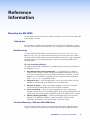
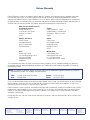
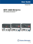
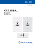
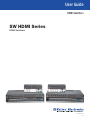
User Guide
HDMI Switchers
SW HDMI Series
HDMI Switchers
68-2312-01 Rev. B
06 13
Safety Instructions
Safety Instructions • English
WARNING: This symbol,
, when used on the product, is intended to
alert the user of the presence of uninsulated dangerous voltage within
the product’s enclosure that may present a risk of electric shock.
Chinese Simplified(简体中文)
警告:
产品上的这个标志意在警告用户该产品机壳内有暴露的危险
电压,有触电危险。
注 意:
ATTENTION: This symbol,
, when used on the product, is intended to alert
the user of important operating and maintenance (servicing) instructions in the
literature provided with the equipment.
For information on safety guidelines, regulatory compliances, EMI/EMF
compatibility, accessibility, and related topics, see the Extron Safety and
Regulatory Compliance Guide, part number 68-290-01, on the Extron
website, www.extron.com.
Instructions de sécurité • Français
AVERTISSEMENT:
Ce pictogramme,
, lorsqu’il est utilisé sur le
produit, signale à l’utilisateur la présence à l’intérieur du boîtier du
produit d’une tension électrique dangereuse susceptible de provoquer
un choc électrique.
ATTENTION: Ce pictogramme,
, lorsqu’il est utilisé sur le produit,
signale à l’utilisateur des instructions d’utilisation ou de maintenance
importantes qui se trouvent dans la documentation fournie avec le
matériel.
Pour en savoir plus sur les règles de sécurité, la conformité à la
réglementation, la compatibilité EMI/EMF, l’accessibilité, et autres sujets
connexes, lisez les informations de sécurité et de conformité Extron, réf. 68290-01, sur le site Extron, www.extron.fr.
产 品 上 的 这个 标 志 意 在 提 示用 户设 备 随 附 的 用 户手 册 中 有
重要的操作和维护(维修)说明。
关于我们产品的安全指南、遵循的规范、EMI/EMF 的兼容性、无障碍
使用的特性等相关内容,敬请访问 Extron 网站 www.extron.cn,参见 Extron
安全规范指南,产品编号 68-290-01。
Chinese Traditional(繁體中文)
警告:
若產品上使用此符號,是為了提醒使用者,產品機殼內存在著
可能會導致觸電之風險的未絕緣危險電壓。
注意
有關安全性指導方針、法規遵守、EMI/EMF 相容性、存取範圍和相關主題的詳細
資訊,請瀏覽 Extron 網站:www.extron.cn,然後參閱《Extron 安全性與法規遵
守手冊》,準則編號 68-290-01。
Japanese
警告: この記号
が製品上に表示されている場合は、筐体内に絶縁されて
いない高電圧が流れ、感電の危険があることを示しています。
Sicherheitsanweisungen • Deutsch
WARNUNG: Dieses Symbol
auf dem Produkt soll den Benutzer darauf
aufmerksam machen, dass im Inneren des Gehäuses dieses Produktes
gefährliche Spannungen herrschen, die nicht isoliert sind und die einen
elektrischen Schlag verursachen können.
VORSICHT: Dieses Symbol
auf dem Produkt soll dem Benutzer
in der im Lieferumfang enthaltenen Dokumentation besonders
wichtige Hinweise zur Bedienung und Wartung (Instandhaltung)
geben.
Weitere Informationen über die Sicherheitsrichtlinien, Produkthandhabung,
EMI/EMF-Kompatibilität, Zugänglichkeit und verwandte Themen finden Sie
in den Extron-Richtlinien für Sicherheit und Handhabung (Artikelnummer 68290-01) auf der Extron-Website, www.extron.de.
若產品上使用此符號,是為了提醒使用者。
注意: この記号
が製品上に表示されている場合は、本機の取扱説明書に
記載されている重要な操作と保守(整備)の指示についてユーザーの
注意を喚起するものです。
安全上のご注意、法規厳守、EMI/EMF適合性、その他の関連項目に
ついては、エクストロンのウェブサイトwww.extron.jp より
『 Extron Safety and Regulatory Compliance Guide 』(P/N 68-290-01) をご覧ください。
Korean
경고: 이 기호
, 가 제품에 사용될 경우, 제품의 인클로저 내에 있는
접지되지 않은 위험한 전류로 인해 사용자가 감전될 위험이 있음을
경고합니다.
Instrucciones de seguridad • Español
Este símbolo,
, cuando se utiliza en el producto,
avisa al usuario de la presencia de voltaje peligroso sin aislar dentro
del producto, lo que puede representar un riesgo de descarga
eléctrica.
ADVERTENCIA:
ATENCIÓN: Este símbolo,
, cuando se utiliza en el producto, avisa
al usuario de la presencia de importantes instrucciones de uso
y mantenimiento recogidas en la documentación proporcionada
con el equipo.
Para obtener información sobre directrices de seguridad, cumplimiento
de normativas, compatibilidad electromagnética, accesibilidad y temas
relacionados, consulte la Guía de cumplimiento de normativas y seguridad de
Extron, referencia 68-290-01, en el sitio Web de Extron, www.extron.es.
주의:
이 기호
, 가 제품에 사용될 경우, 장비와 함께 제공된 책자에 나와
있는 주요 운영 및 유지보수(정비) 지침을 경고합니다.
안전 가이드라인, 규제 준수, EMI/EMF 호환성, 접근성, 그리고 관련
항목에 대한 자세한 내용은 Extron 웹 사이트(www.extron.co.kr)의
Extron 안전 및 규제 준수 안내서, 68-290-01 조항을 참조하십시오.
FCC Class A Notice
This equipment has been tested and found to comply with the limits for a Class A digital device,
pursuant to part 15 of the FCC rules. The Class A limits provide reasonable protection against harmful
interference when the equipment is operated in a commercial environment. This equipment generates,
uses, and can radiate radio frequency energy and, if not installed and used in accordance with the
instruction manual, may cause harmful interference to radio communications. Operation of this
equipment in a residential area is likely to cause interference; the user must correct the interference at
his own expense.
Copyright
© 2013 Extron Electronics. All rights reserved.
Trademarks
All trademarks mentioned in this guide are the properties of their respective owners.
The following registered trademarks®, registered service marks(SM), and trademarks(TM) are the property of
RGB Systems, Inc. or Extron Electronics:
Registered Trademarks (®)
AVTrac, Cable Cubby, CrossPoint, eBUS, EDID Manager, EDID Minder, Extron, Flat Field, GlobalViewer, Hideaway, Inline, IP Intercom, IP Link,
Key Minder, LockIt, MediaLink, PlenumVault, PoleVault, PowerCage, PURE3, Quantum, SoundField, SpeedMount, SpeedSwitch, System
Integrator, TeamWork, TouchLink, V‑Lock, VersaTools, VN‑Matrix, VoiceLift, WallVault, WindoWall
Registered Service Mark(SM) : S3 Service Support Solutions
Trademarks (™)
AAP, AFL (Accu‑Rate Frame Lock), ADSP (Advanced Digital Sync Processing), AIS (Advanced Instruction Set), Auto‑Image, CDRS (Class D
Ripple Suppression), DDSP (Digital Display Sync Processing), DMI (Dynamic Motion Interpolation), Driver Configurator, DSP Configurator, DSVP
(Digital Sync Validation Processing), FastBite, FOXBOX, IP Intercom HelpDesk, MAAP, MicroDigital, ProDSP, QS-FPC (QuickSwitch Front Panel
Controller), Scope‑Trigger, SIS, Simple Instruction Set, Skew‑Free, SpeedNav, Triple‑Action Switching, XTP, XTP Systems, XTRA, ZipCaddy,
ZipClip
Conventions Used in this Guide
Notifications
The following notifications are used in this guide:
CAUTION: A caution indicates a situation that may result in minor injury.
ATTENTION: Attention indicates a situation that may damage or destroy the product or
associated equipment.
NOTE: A note draws attention to important information.
Software Commands
Commands are written in the fonts shown here:
^AR Merge Scene,,Op1 scene 1,1 ^B 51 ^W^C
[01] R 0004 00300 00400 00800 00600 [02] 35 [17] [03]
E X! *X1&* X2)* X2#* X2! CE}
NOTE: For commands and examples of computer or device responses mentioned
in this guide, the character “0” is used for the number zero and “O” is the capital
letter “o.”
Computer responses and directory paths that do not have variables are written in the font
shown here:
Reply from 208.132.180.48: bytes=32 times=2ms TTL=32
C:\Program Files\Extron
Variables are written in slanted form as shown here:
ping xxx.xxx.xxx.xxx —t
SOH R Data STX Command ETB ETX
Selectable items, such as menu names, menu options, buttons, tabs, and field names are
written in the font shown here:
From the File menu, select New.
Click the OK button.
Specifications Availability
Product specifications are available on the Extron website, www.extron.com.
Contents
Introduction.................................................... 1
Remote Communication and Control........ 21
About this Guide.................................................. 1
About the SW HDMI Series Switchers................. 1
Features.............................................................. 1
Application Diagrams........................................... 3
Using Simple Instruction Set (SIS)
Commands...................................................... 21
Host-to-switcher Communications................ 21
Switcher-initiated Messages.......................... 21
Error Responses............................................ 22
Using the Command and Response Table..... 22
Symbol Definitions......................................... 23
Command and Response Table for SIS
Commands ................................................. 24
Updating Firmware Using Firmware Loader....... 27
Downloading and Installing Firmware
Loader.......................................................... 27
Downloading the SW HDMI Firmware............ 27
Loading the Firmware to the Switcher............ 28
Installation...................................................... 4
Installation Overview............................................ 4
Rear Panel Features............................................ 5
Wiring the Power Connector — SW2 and
SW4 HDMI Only (Optional).................................. 7
Wiring for RS-232 Control................................... 8
Connecting to the USB Port................................ 9
Enabling Auto-input Switching........................... 10
Wiring for Input Selection by Contact
Closure............................................................. 11
Wiring the Tally Out Port to Indicate the Input
Selection.......................................................... 12
Operation...................................................... 13
Front Panel Features.......................................... 13
Operations....................................................... 15
Powering on the Switcher.............................. 15
Selecting an Input.......................................... 15
Resetting....................................................... 16
Using the Optional IR 102 Remote
Control......................................................... 16
Locking and Unlocking the Front Panel
(Executive Mode).......................................... 17
EDID Modes.................................................. 17
Reference Information................................ 33
Mounting the SW HDMI..................................... 33
Tabletop Use................................................. 33
Rack Mounting.............................................. 33
Furniture Mounting—SW2 and SW4 HDMI
Only.............................................................. 33
SW HDMI Series • Contents
v
SW HDMI Series • Contents
vi
Introduction
This section gives an overview of the SW HDMI Series switchers. Topics include:
•
About this Guide
•
About the SW HDMI Series Switchers
•
Features
•
Application Diagrams
About this Guide
This guide describes the Extron SW HDMI Series switchers and discusses how to install,
configure, and operate them.
In this guide, the term “SW HDMI Series” refers to the SW2, SW4, SW6, and SW8 HDMI
switchers. “Switcher” and “SW HDMI” are used to refer to any single unit.
About the SW HDMI Series Switchers
The SW HDMI Series are two, four, six, and eight input, one output, High-definition
Multimedia Interface (HDMI) switchers. They allow multiple HDMI input signals, including
digital video, 3D signals, and embedded multi-channel digital audio to be switched to
one compatible output display. These switchers support all standard single-link HDMI (up
to 2.25 Gbps) and Digital Video Interface (DVI) 1.0 signal formats. They are compatible
at 60 Hz with all HDTV resolutions up to 1080p and PC resolutions up to 2048x1080,
with 12-bit color, and are fully compliant with High-bandwidth Digital Content Protection
(HDCP).
The SW HDMI switchers can be controlled via the front panel, the RS-232 interface, USB,
contact closure, or the optional IR 102 Remote Control. You can select inputs by pressing
the front panel buttons, pressing buttons on the IR 102, enabling auto-input switching,
attaching a jumper or a contact closure device to the Contact port, or entering Simple
Instruction Set (SIS) commands via RS-232 or USB.
Features
•
HDCP authentication — The SW HDMI switchers check the sources and the
display individually for HDCP compliance. HDCP LEDs for each input and the output
indicate successful HDCP authentication.
•
Auto-input switching — The SW HDMI Series can be configured to automatically
switch to the highest-numbered active input when the switcher detects a signal.
•
Signal detection LEDs — Each input and the output are represented by front panel
LEDs, which light if a signal is present for the input or output and there is activity on
the Transition Minimized Differential Signaling (TMDS) lines.
•
Contact closure — The Contact port enables inputs to be selected by contact
closure, with or without a contact closure device.
•
Tally output port — Can be used in conjunction with the Contact port to indicate
the selected switcher input.
SW HDMI Series • Introduction
1
•
Rack and furniture mounting — The SW HDMI Series can be mounted on a rack
shelf or under a desk or podium with an optional mounting kit.
•
Remote configuration and control — The switcher can be configured via an RS-232
or USB connection via SIS commands (see Remote Communication and Control
beginning on page 21).
•
EDID Minder — A proprietary EDID (Extended Display Identification Data) management
process from Extron, the EDID Minder manages the EDID between a digital display
device and one or more input sources. By maintaining continuous EDID communication
with all sources, EDID Minder ensures that digital sources power up properly and
maintain their video output, whether or not they are actively connected to the digital
display device.
•
EDID modes — Either of the following EDID modes can be selected using SIS
commands:
•
Automatic, in which the SW HDMI reads the EDID data when a display is
connected and stores the data in memory (default mode)
•
User-assigned, in which you can assign one of 48 factory-provided EDID files
to each input. Four undefined memory slots are also provided, to which you can
save the EDID of connected displays as additional EDID files. The assigned EDID
does not change if a different display device is connected. This mode is useful for
troubleshooting purposes.
Each time power is applied to the output device or when the display is replaced, the
SW HDMI either reads the EDID information from the display or reloads the userassigned EDID information. It then writes the information to non-volatile memory on the
inputs. The input devices can read this information as they reboot (see EDID Modes on
page 17 for more information).
•
Output compatibility correction — The SW HDMI monitors the EDID on the
connected output device to ensure that it is compatible with the currently selected input
signal. The following corrections are made to the signal as necessary each time an input
is selected:
•
Interface format: If the connected output device is DVI and the selected source is
HDMI, the signal is reformatted for DVI. If the output device is an HDMI device, no
reformatting is necessary because HDMI is backwards compatible with DVI.
•
Video color bit depth: If the connected output device does not support the color
bit depth of the selected source signal, it is truncated to the next level down that is
supported. For example, 12-bit >10-bit > 8-bit. Bit depth truncation can be forced
via SIS commands to always downgrade to 8-bit depth, disabling deep color.
•
IR remote control (optional) — The hand-held IR 102 Remote Control can control
the SW HDMI via infrared signals that it sends to the switcher from a distance of up to
30 feet (9 m).
•
Front panel security lockout (executive mode) — To prevent unauthorized access
to the switchers, the front panel controls can be locked via the front panel buttons or
SIS commands (RS-232, USB, and IR control remain available).
•
Input cable equalization — Automatic input cable equalization compensates for
signal loss when long cable assemblies are used.
•
Power supply —
•
SW2 and SW4 HDMI: An energy-efficient, external 12 VDC, 1 A universal power
supply with a 2-pole captive screw connector accepts 100 to 240 VAC.
•
SW6 and SW8 HDMI: An 50-60 Hz, internal universal power supply with a
standard IEC connector accepts 100 to 240 VAC.
SW HDMI Series • Introduction
2
Application Diagrams
The following diagrams show examples of how SW HDMI Series switchers can be
connected.
VCR
DVD
DOC
CAM
P
LAPTO
PC
ON
OFF
Y
DISPLA
MUTE
N
SCREE
UP
N
SCREE
DOWN
TouchLink
Control
System
TCP/IP
E
OT
M
RE
UT
YO
LL
TO
TA
UT
+v
TP
OU
1
1
4
3
T
AC
NT
2
CO
2
-232
4
AU
RS-232
RS
Tx
3
Rx
®
100
G
INPUT
IR
RX
250
LINK
3
ACT
1
4
3
2
1
4
TX
2
1
2
R
TS
RELAY
3
1
COM
IPL
4
2
3
4
PU
IN
3
1
WER
POV
12 MAX
0.3A
Extron
SW4 HDMI
HDMI
Cables
Flat Panel
Display with
Integrated
Speakers
Switcher
Laptop
Blu-ray Player
DSS Receiver
PC
Figure 1.
Application Diagram for an SW4 HDMI Switcher
NOTE: HDCP compliant sources require HDCP compliant displays (see the user
manual of the source or display device for information on its HDCP compliance).
TouchLink
Control
System
VCR
DVD
DOC
CAM
LAPTOP
PC
ON
OFF
DISPLAY
MUTE
SCREEN
UP
SCREEN
DOWN
MI
8 HD
SW
TCP/IP
TE
MO
RE
TO
1
2
3
UT
TP
6
5
+V OUT
4
LLY
TA
T
AC
NT
CO
OU
1
2
3
4
G
5
6
7
8
+V
Tx
7
AU
2
-23
RS
8
Rx
G
G
®
100
INPUT
IR
RELAY
LINK
3
ACT
1
3
1
COM
RX
8
HDMI
Cables
IPL
250
2
4
TX
2
1
2
R
4
3
1
4
2
3
RS-232
7
6
TS
PU
IN
5
4
3
2
X
A MA
0.2
0V
-24
1
Flat Panel
Display with
Integrated
Speakers
100
Extron
SW8 HDMI
z
60H
50-
HDMI
Cables
Switcher
Blu-ray Player
Laptop
Laptop
PC
Figure 2.
Laptop
DSS Receiver
Application Diagram for an SW8 HDMI Switcher
SW HDMI Series • Introduction
3
Installation
This section describes the installation and setup of the SW HDMI Series switchers. Topics
include:
•
Installation Overview
•
Rear Panel Features
•
Wiring the Power Connector — SW2 and SW4 HDMI Only (Optional)
•
Wiring for RS-232 Control
•
Connecting to the USB Port
•
Enabling Auto-input Switching
•
Wiring for Input Selection by Contact Closure
•
Wiring the Tally Out Port to Indicate the Input Selection
Installation Overview
To install and set up the SW HDMI switcher:
1. Turn off all equipment and disconnect it from the power source.
2. (Optional) Mount the switcher on a rack shelf or furniture (see Mounting the
SW HDMI on page 33).
3. Connect HDMI input sources to one or more of the SW HDMI input connectors.
4. Connect an HDMI output device to the output connector.
5. Connect control devices. Connect your computer to either of the following
SW HDMI ports to configure and control the switcher via SIS commands:
•
RS-232 port — Pins 1, 2, and 3 of the RS-232/Auto connector for serial RS-232
control (see Wiring for RS-232 Control on page 8 for connection procedures)
•
Config port — USB mini B connector for USB control (see Connecting to the
USB Port on page 9 for connection procedures)
6. (Optional) Enable auto-input switching. Use a jumper to connect pins 4 and 5 of
the 5-pole captive screw plug that you plugged into the RS-232 connector in step 5
(see Enabling Auto-input Switching on page 10).
7. (Optional) Connect an input device to the SW HDMI Contact port (directly or through
a contact closure device) and, if desired, to the Tally Out port, to enable input
switching by contact closure (see Wiring for Input Selection by Contact Closure
on page 11).
8. Power on the output display.
9. Connect power to the switcher (see Powering On the Switcher on page 15).
10. (Optional) Configure the EDID Minder. By default, the SW HDMI is configured to
automatically store the EDID of the display (automatic mode). If desired, change the
EDID mode to prevent automatic EDID storage and enter the desired EDID manually
(see EDID Modes on page 17).
11. Power on the source devices.
SW HDMI Series • Installation
4
Rear Panel Features
6
SW2 HDMI
INPUTS
1
OUTPUT
REMOTE
TALLY OUT
2
POWER
12V
0.4A MAX
1
2
4 +v
3
CONTACT
1
1
3
4 G
RS-232 AUTO
Tx Rx
4
3
2
Figure 3.
2
5
SW2 HDMI Rear Panel
6
SW4 HDMI
INPUTS
1
2
OUTPUT
3
REMOTE
TALLY OUT
4
POWER
12V
0.4A MAX
1
2
3
4 +v
CONTACT
1
1
2
Figure 4.
2
3
4 G
RS-232 AUTO
Tx Rx
5
4
3
SW4 HDMI Rear Panel
6
100-240V
0.2A MAX
INPUTS
1
2
3
OUTPUT
4
5
4 +V 5 6
TALLY OUT
1
2 3
4 G 5
+V
CONTACT
6
REMOTE
RS-232
G
AUTO
Tx Rx G
5
4
3
2
Figure 5.
2 3
6
50-60Hz
1
SW6 HDMI
1
SW6 HDMI Rear Panel
6
100-240V
0.2A MAX
INPUTS
1
2
3
4
OUTPUT
5
6
7
2
Figure 6.
2 3
4 +V 5 6
TALLY OUT
1
2 3
4 G 5
8
7 8 +V
CONTACT
50-60Hz
1
SW8 HDMI
1
3
6
REMOTE
RS-232
7 8 G
4
AUTO
Tx Rx G
5
SW8 HDMI Rear Panel
SW HDMI Series • Installation
5
a
Power connector —
•
SW2 and SW4 HDMI: Plug the provided external 12 VDC, 1 A power supply into
this 2-pole, 3.5 mm captive screw connector and into an AC power outlet.
ATTENTION: Do not connect power to the switcher until you have read the
CAUTION and ATTENTION notices on the next page.
•
b
Input connectors — Connect HDMI video input sources to these female Type A
single-link HDMI connectors. Data rates of up to 6.75 Gbps are supported.
•
LockIt brackets: LockIt cable lacing brackets, one for each HDMI input and the
output connector, are provided with the SW HDMI. These brackets secure the
HDMI cables to the rear panel connectors and reduce stress on the connectors,
preventing signal loss due to loose cable connections. For information on
attaching the LockIt brackets, see the LockIt HDMI Cable Lacing Bracket
Installation Guide, available at www.extron.com.
•
c
SW6 and SW8 HDMI: Plug the provided AC power cord into this male IEC
connector and into an AC power outlet.
EDID information: By default, EDID is read from the output device and written
to switcher memory for each input, allowing each source to see the EDID
information for the output device even when the SW HDMI is switching between
sources.
Output connector — Connect an HDMI display device to this female Type A HDMI
connector.
The EDID information is read from the connected output device via this connector and
is written to memory on each input whenever the output device is connected to this
port and powered on.
NOTE: The EDID information is also read and stored whenever power is recycled
to the connected output device or when the output device is replaced.
d
Contact port — Plug one of the provided 5-pole captive screw connectors into this
5-pole, 3.5 mm captive screw port. On the SW6 and SW8 HDMI, plug connectors
into either or both parts of the dual Contact port. You can use this port to switch
inputs by:
•
Shorting the ground pin to any of the other four pins in the connector (see
Contact Closure under “Selecting an Input” on page 15).
•
e
Connecting a push-button contact closure device to the port (see Wiring for
Input Selection by Contact Closure on page 11).
Remote and auto-input switching connector — This 5-pole, 3.5 mm captive
screw connector (labeled “RS-232 Auto”) can be used for RS-232 communication
with the switcher (including firmware updates) and to enable auto-input switching.
•
To enable RS-232 control, connect the Tx (transmit), Rx (receive) and G
(ground) pins to the serial port of your computer (see Wiring for RS-232 Control
on page 8).
•
To enable auto-input switching, short pins 4 and 5 of this connector together.
In auto-input switch mode, the switcher automatically switches to the highest
numbered active input (see Enabling Auto-input Switching on page 10).
SW HDMI Series • Installation
6
f
Tally Out port — (Optional) Plug one of the provided 5-pole captive screw
connectors into this 5-pole captive screw port to indicate which input has been
selected. On the SW6 and SW8 HDMI, plug connectors into either or both parts of
the dual Tally Out port.
Connect an indicator device such as an LED to the attached connector to identify the
currently selected input when the front panel buttons are not visible (see Wiring the
Tally Out Port to Indicate the Input Selection on page 12).
Wiring the Power Connector — SW2 and SW4 HDMI Only (Optional)
A 12 VDC, 1 A power supply is provided with the SW2 and SW4 HDMI. Should it be
necessary to attach a 2-pole captive screw connector to your power supply, follow these
instructions:
CAUTION: Risk of electric shock. The two power cord wires must be kept
separate while the power supply is plugged in. Remove power before wiring.
ATTENTION:
• The power supply must not be permanently fixed to the building structure or
similar structures.
• The power supply must not be located within environmental air handling spaces
or the wall cavity.
• The installation must be in accordance with the applicable provisions of the
National Electrical Code ANSI/NFPA 70, Article 725 and the Canadian Electrical
Code, Part 1, Section 16.
• The power supply must be located in the same vicinity as the Extron AV
processing equipment in an ordinary location, Pollution Degree 2, secured to a
podium, a desk, or an equipment rack within a dedicated closet.
• Always use a power supply specified for the SW HDMI by Extron. Use of an
unauthorized power supply voids all regulatory compliance certification and may
cause damage to the supply and the switcher.
1. Cut the DC output cord to the length needed.
2. Strip the jacket to expose 3/16 inch (5 mm) of the conductors.
ATTENTION:
• Exposing more than 3/16 inch (5 mm) of the copper wires could allow the
stripped wires to touch each other, causing a short circuit. This could result
in the external DC power supply overheating and burning.
• Stripping the wires to expose less than the recommended amount may
cause them to slide out of the connector too easily, even if they are tightly
pinched by the captive screws.
• Do not tin the stripped power supply leads before attaching the captive
screw plug to them. Tinned wires are not as secure in the captive screw
connectors and can be easily pulled out. They may also break after being
bent several times.
3. Slide the leads into the supplied 2-pole captive screw plug and secure them, using a
small screwdriver.
4. To verify the power cord polarity before connecting the plug, connect the power
supply with no load and check the output with a voltmeter.
SW HDMI Series • Installation
7
5. Use the supplied tie wrap to strap the power cord to the extended tail of the
connector.
Heat
Shrink
7/8"
(22 mm)
1/8"
(3 mm)
Captive Screw Connector
3/16"
(5 mm) Max.
Figure 7.
Tie Wrap
Wiring the Power Connector
Wiring for RS-232 Control
Use a female 9-pin D to bare wire RS-232 cable or a universal control cable (UC50' or
UC100') to connect your computer or control system to the RS-232 pins of the Remote
connector.
1. Wire the unterminated end of the RS-232 cable to the provided 5-pole captive screw
plug as described below. Connect the transmit, receive, and ground wires of the
cable to the first three pins on the connector, starting at the left:
•
Connect the transmit wire to pin 1, which plugs into the Tx (transmit) port.
•
Connect the receive wire to pin 2, which plugs into the Rx (receive) port.
•
Connect the ground wire to pin 3, which plugs into the G (ground) port.
2. Plug the 5-pole connector into the Remote receptacle on the rear panel of the
switcher.
3. Connect the other end of the cable to the appropriate computer or control system
connector.
Figure 8 shows how to wire this shared connector for RS-232.
RS-232 Auto
Tx Rx G
SW HDMI Series Switcher
Rear Panel
Remote Port
NOTE: If you use cable that has a drain
wire, tie the drain wire to ground at both ends.
Ground (G)
Receive (Rx)
Transmit (Tx)
Transmit (Tx)
Receive (Rx)
Computer or
Control System
RS-232 Port
Figure 8.
Remote Connector Pin Assignments
SW HDMI Series • Installation
8
Connecting to the USB Port
The mini B USB port is located on the SW HDMI front panel. It can be used to configure
the switcher via SIS commands.
1. Connect a USB A to mini B cable between the USB Config port on the switcher front
panel and the USB port on your computer.
USB Mini B
USB A
USB 1
USB
Ports
USB Cable
INPUTS
INPUTS
AUTO
SWITCH
IR
1
2
3
4
OUTPUT
SIGNAL
1
2
3
4
HDCP
CONFIG
SW4 HDMI
HDMI SWITCHER
SW HDMI Front Panel
Figure 9.
Computer
USB Port Connection
2. If this is the first time you have connected an SW HDMI to this USB port on your
computer, the Found New Hardware Wizard opens. On the first screen, specify
whether you want the computer to connect to Windows Update in order to search the
web for the driver that it needs to communicate with the switcher via the USB port.
This is not necessary if the USB driver already exists on your computer.
Figure 10.
•
Found New Hardware Wizard Opening Screen
Select the Yes, this time only radio button if you want your computer to
connect to Windows Update only this one time.
SW HDMI Series • Installation
9
•
Select Yes, now and every time I connect a device if you want the computer
to automatically connect to Windows Update to search the web every time the
switcher is connected to this USB port.
•
Select No, not this time if you do not want the computer to connect to
Windows Update to search the web at this time (for example, if the driver is
already on your computer).
3. Click Next. On the next screen, select the Install the software automatically
(Recommended) radio button, then click Next (you do not need to insert a disc).
Figure 11.
Selecting the Radio Button to Install the USB Driver
Automatically
Your computer locates the driver needed for it to communicate with the SW HDMI via
the USB port and loads it to the computer hard drive.
4. When the Completed screen appears, click Finish to close the wizard.
NOTE: This wizard appears only the first time you connect the SW HDMI to each
USB port. You do not see the wizard again unless you connect the switcher to
a different USB port on your computer.
5. Configure the switcher as desired using SIS commands (see the Remote
Communication and Control section, beginning on page 21 for information on
available commands).
Enabling Auto-input Switching
You can set up the SW HDMI to automatically select the active, connected input based on
detection of an active video signal (TMDS clock activity). If two or more inputs are active,
the highest-numbered input port with an active signal is selected (for example, input 4 on
an SW4 HDMI switcher). When auto-input switching is in effect, the green Auto Switch
LED on the front panel lights and the front panel input buttons are disabled.
To enable auto-input switching:
1. Cut a small piece of wire to use as a jumper.
2. Insert the ends of the wire into slots 4 and 5 of the provided 5-pole captive screw
plug, connecting pins 4 and 5 together.
SW HDMI Series • Installation
10
3. Use a small screwdriver to tighten the two screws above pin slots 4 and 5 of the plug
so that the jumper wire ends remain securely in place (see figure 12).
4. Insert the plug into the 5-pole Remote captive screw connector on the rear panel.
Figure 12 shows an SW4 HDMI with a jumper connecting pins 4 and 5 to enable
auto-input switching.
FIG_Auto-input switching
TE
MO
RE
UT
YO
LL
TO
TA
T
U
TP
OU
1
1
TS
PU
IN
2
3
+v
4
2
AU
T
AC
NT
CO
3
2
-23
RS
4
Tx
Rx
G
4
3
2
1
R
WE
POV X
12 MA
A
0.3
Figure 12. Auto Pins of the Remote Connector with a Jumper Installed
Auto-input switching remains in effect as long as the jumper wire connects the two pins
and the 5-pole captive screw plug is attached to the RS-232/Auto port.
Wiring for Input Selection by Contact Closure
The Contact port provides an alternative method of input selection. Connect a
push-button contact closure device to this port to switch the desired input to the output
as follows:
1. Plug one of the provided 5-pole connectors into the Contact port. On the SW6 and
SW8 HDMI, plug connectors into either or both parts of the dual Contact port.
2. Insert the signal wire of the contact closure device into the slot representing the
desired input number on the SW HDMI Contact port.
Pin 1 = Input 1 contact
Pin 2 = Input 2 contact
Pin 3 = Input 3 contact (SW4, SW6, and SW8 HDMI only)
Pin 4 = Input 4 contact (SW4, SW6, and SW8 HDMI only)
Pin 5 (G) = Contact ground
Pin 6 = Input 5 contact (SW6 and SW8 HDMI only)
Pin 7 = Input 6 contact (SW6 and SW8 HDMI only)
Pin 8 = Input 7 contact (SW8 HDMI only)
Pin 9 = Input 8 contact (SW8 HDMI only)
Pin 10 (G) = Contact ground (SW6 and SW8 HDMI only)
3. Insert the ground wire of the contact device into the G slot of the Contact port (pin 5
or 10).
After wiring the connector, press the button on the contact device to switch the
connected input to the output.
SW HDMI Series • Installation
11
Wiring the Tally Out Port to Indicate the Input Selection
To identify the currently selected input when the front panel buttons are not visible, you
can connect an indicator device such as an LED to an input pin and the +V pin of the Tally
Out port. When the input you are using is selected, the corresponding tally out pin shorts
to ground, which activates the connected indicator.
To connect an indicator to the Tally Out port:
1. Plug one of the provided 5-pole
connectors into the Tally Out port. On the
SW6 and SW8 HDMI, plug connectors
into either or both parts of the dual Tally
Out port.
REMOTE
Tally Out Port for
Input Selection
Indication
TALLY OUT
1
2
3
4 +v
CONTACT
2. Insert the power wire for the contact
indicator device into the +V slot of the
Tally Out connector (pin 5).
1
2
3
4 G
RS-232 AUTO
Tx Rx
3. Insert the ground wire for the indicator into the slot on the Tally Out port that
represents the input that you want to monitor.
Pin 1 = Input 1 tally ground
Pin 2 = Input 2 tally ground
Pin 3 = Input 3 tally ground (SW4, SW6, and SW8 HDMI only)
Pin 4 = Input 4 tally ground (SW4, SW6, and SW8 HDMI only)
Pin 5 = +5 V
Pin 6 = Input 5 tally ground (SW6 and SW8 HDMI only)
Pin 7 = Input 6 tally ground (SW6 and SW8 HDMI only)
Pin 8 = Input 7 tally ground (SW8 HDMI only)
Pin 9 = Input 8 tally ground (SW8 HDMI only)
Pin 10 = +5 V (SW6 and SW8 HDMI only)
Example: One way to use this port is to connect it to a contact closure device with an
LED. Connect the contact device to the Contact port as well. When you use the contact
device to switch the input you are using, the LED lights.
SW HDMI Series • Installation
12
Operation
This section describes the operation of the SW HDMI Series switchers. Topics include:
•
Front Panel Features
•
Operations
Front Panel Features
1
2
3
4
INPUTS
INPUTS
IR
AUTO
SWITCH
1
OUTPUT
SIGNAL
2
1
2
HDCP
CONFIG
SW2 HDMI
HDMI SWITCHER
5
6
Figure 13. SW2 HDMI Front Panel
1
2
AUTO
SWITCH
IR
3
4
INPUTS
INPUTS
1
2
3
4
OUTPUT
SIGNAL
1
2
3
4
HDCP
CONFIG
SW4 HDMI
HDMI SWITCHER
5
6
Figure 14. SW4 HDMI Front Panel
1
2
AUTO
SWITCH
IR
3
4
INPUTS
1
2
3
OUTPUT
INPUTS
4
5
6
CONFIG
SIGNAL
1
2
3
4
5
6
HDCP
SW6 HDMI
HDMI SWITCHER
5
6
Figure 15. SW6 HDMI Front Panel
SW HDMI Series • Operation
13
1
2
AUTO
SWITCH
IR
4
3
INPUTS
1
2
3
4
INPUTS
5
6
7
8
OUTPUT
SIGNAL
1
2
3
4
5
6
7
8
HDCP
CONFIG
SW8 HDMI
HDMI SWITCHER
6
Figure 16. SW8 HDMI Front Panel
5
a
Auto Switch LED — This LED lights when auto-input switching is in effect (see
Enabling Auto-input Switching on page 10 for the procedure to set up automatic
input selection).
b
IR receiver port — This sensor detects infrared signals from the optional IR 102
remote control at a distance of up to 30 feet and within 40 degrees off the axis (see
Using the Optional IR 102 Remote Control on page 16).
c
Input selection buttons and LEDs — Press one of these buttons to select an
input to switch to the output. The LED at the right of each button lights when the
corresponding input is selected. If auto-input switching is in effect, these buttons are
disabled, but the LEDs continue to light to indicate the selected input.
The input buttons are also used to initiate a system reset (see Resetting on page 16)
and to enable and disable front panel lockout (see Locking and Unlocking the
Front Panel (Executive Mode) on page 17).
d
Signal status LEDs —
•
Inputs: Each input has a corresponding numbered Signal LED, which lights when
a source is connected to the input connector and TMDS clock activity is detected
on it.
NOTE: If the source device connected to the selected input is HDCP
encrypted (requires HDCP authentication), the corresponding signal LED
may not light unless HDCP has been authenticated.
•
e
Output: The Output Signal LED lights when an active sink (output) device is
connected to the HDMI output.
HDCP status LEDs —
Inputs: Each input has a corresponding numbered HDCP LED. If the connected
source requires HDCP, the corresponding LED lights when authentication is
successful.
•
NOTE: HDCP is authenticated on each input regardless of the currently
selected source.
•
Output: The Output HDCP LED lights if the currently selected input requires
HDCP and the connected output device has been successfully authenticated.
NOTE: HDCP is re-authenticated on the output whenever a new input is
selected.
f
Config port — Connect a USB cable (USB A to mini B) between your computer
and this female USB mini B port to configure and control the switcher via SIS
commands or the Universal Switcher Control Program and to update the firmware
(see Connecting to the USB Port on page 9).
SW HDMI Series • Operation
14
Operations
Powering on the Switcher
To power on the SW HDMI:
1. Connect all input and output devices to the rear panel connectors on the switcher (see
Rear Panel Features on page 5 for the rear panel connections).
2. Power on the display.
3. Power on the SW HDMI:
•
SW2 and SW4 HDMI: Plug the power supply into the 2-pole captive screw
power connector on the switcher rear panel.
•
SW6 and SW8 HDMI: Plug the provided IEC cord into the rear panel IEC
connector and an AC outlet.
After approximately 4 seconds, the following happens:
•
The unit performs a self-test, during which the front panel Auto Switch, Input,
Signal, and HDCP LEDs each blink once in sequence from left to right. When the
self-test completes, the LED for the most recently selected input remains lit.
•
The switcher reads the available EDID information from the connected output
device and writes it to memory on each input. When power is removed, these
settings remain in memory and are in effect when power is reapplied.
NOTE: If EDID Minder is in automatic mode, the settings revert to the default
EDID unless a display is connected to the HDMI output port (see EDID
Modes on page 17).
4. Power on the input devices.
Selecting an Input
To switch (tie) an input to the output, you have the following options:
•
•
Front panel buttons: Press the desired input button on the front panel (ensure that
auto-input switching is not enabled). The LED corresponding to the selected input
button lights.
•
The appropriate front panel input LED lights to indicate the selected input. The
LED remains lit until a new input is selected.
•
Only one input can be switched to the output at a time.
Contact closure: Plug one of the provided 5-pole captive screw connectors into the
rear panel Contact port. Wire either of the following to the port:
•
Contact closure device: If a push-button contact closure device is attached to
the Contact port, press the button that is connected to the slot that corresponds
to the desired input.
•
Jumper wire: On the connector attached to the Contact port, momentarily short
one of the input pins (1 through 8, depending on your model) to the ground pin
(pin G) using a jumper wire. For example, shorting pin 1 to pin G selects input 1.
Input is switched immediately when the jumper contacts both pins.
NOTE: If an input pin is latched permanently to the ground pin, input
switching by any other method is disabled while those pins are connected.
See Wiring for Input Selection by Contact Closure on page 11 for more
information.
SW HDMI Series • Operation
15
Other ways to select an input include using SIS commands (see the Input Selection
command on page 24) and optional IR remote control (see “Using the Optional IR 102
Remote Control”).
Resetting
To reset the switcher to its factory default settings:
1. Press and hold the Input 1 button while power is being applied to the unit.
2. Continue holding the Input 1 button until the power-up sequence completes.
Using the Optional IR 102 Remote Control
The optional hand-held IR 102 Remote Control lets you remotely perform functions that
are also available through the front panel buttons and SIS commands.
The IR receiver port on the front panel is located to the right of the Auto Switch LED. It
receives signals from the remote control if they are sent from within a 40-degree arc to
the right or left of the IR receiver sensor, and from no more than 30 feet (9 m) away (see
figure 17).
INPUTS
INPUTS
IR
AUTO
SWITCH
1
2
3
4
1
CONFIG
OUTPUT
SIGNAL
2
3
4
HDCP
SW4 HDMI
HDMI SWITCHER
SW HDMI Series Switcher
40
40
30’
Maximum
1
2
5
6
9
0
Channel
3
7
4
8
+10
IR 102
Universal Remote
1
IR 102 Remote Control
Figure 17. Area for Remote Signal Reception
INPUT/OUTPUT SELECTION
2
3
5
6
9
0
7
4
8
1
+10
Remote control buttons
2
On the IR 102 remote control, buttons 1 through 8
(depending on your model) select inputs. Button 0 mutes
(deselects) all inputs.
a
Input Selection buttons — Press one of these
buttons to select an input.
b
Input mute button (0) — Press this button to
deselect all inputs, effectively muting the output.
IR 102
Universal Remote
SW HDMI Series • Operation
16
Locking IR remote access
The SW HDMI can be set to lock out users from using the IR 102 Remote Control to
control the switcher. Remote access can be enabled and disabled via SIS commands
(see the Front Panel IR Receiver Enable and Disable commands on page 25). When
remote access is disabled, all switcher controls remain available through the SW HDMI
front panel.
Locking and Unlocking the Front Panel (Executive Mode)
Front panel lock mode disables all front panel controls, locking out users from those
functions (RS-232, USB, and IR control remain available). Putting the switcher in lock
mode enhances security by protecting against inappropriate or accidental changes to
settings. If a front panel button is pressed during lock mode, all front panel LEDs blink
once.
To lock or unlock the front panel, press and hold Input buttons 1 and 2 simultaneously for
3 seconds, then release. The front panel LEDs blink three times, indicating that executive
mode has been enabled or disabled (see figure 18).
1
2
Release buttons.
LEDs blink 3 times.
Press and hold simultaneously
for 3 seconds.
Figure 18. Enabling or Disabling Executive Mode
EDID Modes
The SW HDMI switchers utilize the EDID Minder, which maintains EDID communication to
all connected sources, whether or not any of the sources are selected. EDID information
consists of the display resolution, refresh rate, data rate, supported audio formats, and
other parameters. By factory default, the EDID stored on all inputs contains information for
a native resolution of 720p @ 60 Hz, 2-channel audio.
EDID Minder can be configured in two modes: automatic and user-assigned.
Automatic EDID mode
In automatic mode, the switcher automatically stores EDID from the connected display
and communicates it to the inputs; no other configuration is required. This is the default
mode.
•
Reading and storage process — Each time a display is connected to the HDMI
output while the power is connected, the SW HDMI reads the EDID from the display
device and stores it in memory for each input. This information is retained after the
display is disconnected. However, it is overwritten if a new display is connected or a
user assigned EDID file is selected.
•
Default EDID — When the switcher is in automatic mode, the default EDID
(720p @ 60 Hz, 2-channel audio) is stored at each input until a display is connected,
at which time it is overwritten.
SW HDMI Series • Operation
17
User-assigned EDID mode
In this mode, you can select an EDID file that is stored on the switcher. The selected EDID
is stored in memory for the inputs and is not overwritten. The switcher does not obtain
EDID information from the display.
You may want to use this mode if there is a problem with automatic communication of
the EDID information from the attached display, and you want to ensure that the correct
information is stored on the inputs. Also, because this mode disables automatic EDID
reading and storage, you can retain one set of EDID information on the inputs and not
have it changed when another display is connected.
•
Factory-loaded EDID files — You can select from a list of 48 EDID files that
are loaded on the switcher at the factory. Each EDID file contains a unique native
resolution (and audio support if applicable). The EDID table on the next page shows
the EDID files that are provided with the switcher.
•
User-loaded EDID file — In addition to the 48 EDID files provided with the switcher,
four empty memory locations (50 through 53) are provided. You can use these
memory locations to save the EDID of the display that is currently connected to the
output port of the switcher. Any of these four EDID files can then be selected as one
of the user-assigned EDID files.
Changing the EDID mode
EDID modes can be switched only by SIS command. By default, the SW HDMI is in
automatic EDID mode. To change between automatic and user-assigned modes, enter
the following SIS command:
E A X$ EDID }
where X$ is 49 (auto mode) or the number of the user-assigned EDID file that you want to
select (1 through 53) (see the Remote Communication and Control section, beginning
on page 21, for instructions for entering SIS commands via RS-232 or USB).
NOTE: The switcher remains in the selected EDID mode after power is recycled. If the
unit is reset to factory defaults, it reverts to automatic mode.
See the table on the next page for a list of supported EDIDs.
SW HDMI Series • Operation
18
EDID table
EDIDs listed in this table are arranged according to video format: DVI or HDMI. Within
each video format grouping, the EDIDs are listed by rate type: PC or HDTV. Within each
rate type grouping, the EDIDs are listed in order of resolution.
X$
Native
Resolution
Refresh Rate
Rate
Type1
Video
Format2
Audio
Type3
X$
Native
Resolution
Refresh
Rate
Rate
Type1
Video
Format2
Audio
Type3
1
800 x 600
60 Hz
PC
DVI
n/a
28
1680 x 1050
60 Hz
PC
HDMI
2-Ch
2
1024 x 768
60 Hz
PC
DVI
n/a
29
1920 x 1200
60 Hz
PC
HDMI
2-Ch
3
1280 x 720
60 Hz
PC
DVI
n/a
30
2048 x 1080
60 Hz
PC
HDMI
2-Ch
4
1280 x 768
60 Hz
PC
DVI
n/a
31
480p
60 Hz
HDTV
HDMI
2-Ch
5
1280 x 800
60 Hz
PC
DVI
n/a
32
576p
50 Hz
HDTV
HDMI
2-Ch
6
1280 x 1024
60 Hz
PC
DVI
n/a
33
720p
50 Hz
HDTV
HDMI
2-Ch
7
1360 x 768
60 Hz
PC
DVI
n/a
34
720p (default)
60 Hz
HDTV
HDMI
2-Ch
8
1366 x 768
60 Hz
PC
DVI
n/a
35
1080i
50 Hz
HDTV
HDMI
2-Ch
9
1400 x 1050
60 Hz
PC
DVI
n/a
36
1080i
60 Hz
HDTV
HDMI
2-Ch
10
1440 x 900
60 Hz
PC
DVI
n/a
37
1080p
50/25 Hz
HDTV
HDMI
2-Ch
11
1600 x 900
60 Hz
PC
DVI
n/a
38
1080p
50
HDTV
HDMI
2-Ch
12
1600 x 1200
60 Hz
PC
DVI
n/a
39
1080p
60/24 Hz
HDTV
HDMI
2-Ch
13
1680 x 1050
60 Hz
PC
DVI
n/a
40
1080p
60 Hz
HDTV
HDMI
2-Ch
14
1920 x 1080
60 Hz
PC
DVI
n/a
41
720p
50 Hz
HDTV
HDMI
Multi-Ch
15
1920 x 1200
60 Hz
PC
DVI
n/a
42
720p
60 Hz
HDTV
HDMI
Multi-Ch
16
2048 x 1080
60 Hz
PC
DVI
n/a
43
1080i
50 Hz
HDTV
HDMI
Multi-Ch
17
800 x 600
60 Hz
PC
HDMI
2-Ch
44
1080i
60 Hz
HDTV
HDMI
Multi-Ch
18
1024 x 768
60 Hz
PC
HDMI
2-Ch
45
1080p
50/25 Hz
HDTV
HDMI
Multi-Ch
19
1280 x 768
60 Hz
PC
HDMI
2-Ch
46
1080p
50 Hz
HDTV
HDMI
Multi-Ch
20
1280 x 800
60 Hz
PC
HDMI
2-Ch
47
1080p
60/24 Hz
HDTV
HDMI
Multi-Ch
21
1280 x 1024
60 Hz
PC
HDMI
2-Ch
48
1080p
60 Hz
HDTV
HDMI
Multi-Ch
22
1360 x 768
60 Hz
PC
HDMI
2-Ch
49
Automatic (output)
23
1366 x 768
60 Hz
PC
HDMI
2-Ch
50
User-loaded slot 1
24
1400 x 1050
60 Hz
PC
HDMI
2-Ch
51
User-loaded slot 2
25
1440 x 900
60 Hz
PC
HDMI
2-Ch
52
User-loaded slot 3
26
1600 x 900
60 Hz
PC
HDMI
2-Ch
53
User-loaded slot 4
27
1600 x 1200
60 Hz
PC
HDMI
2-Ch
1, 2, 3
See Footnotes for the EDID table on the next page.
SW HDMI Series • Operation
19
Footnotes for the EDID table
The following footnotes apply to the EDID table on the previous page:
Rate type
1
•
PC: These are primarily VESA standard computer rates, based on the most commonly
used native resolutions. They are designed to be used with computer sources.
•
HDTV: These are video rates standardized by SMPTE and CEA. They are designed to be
used with video and computer sources.
Video format
2
DVI: These are 128-byte EDID files, which specify a DVI sink. They do not contain an
extension block.
HDMI: These are 256-byte EDID files, each containing a CEA extension block. They each
specify an HDMI sink device with audio support.
3
Audio type
•
n/a: These are DVI formatted EDID files. They do not support audio.
•
2-Ch: These are HDMI formatted EDID files with support for basic 2-channel (stereo)
audio.
•
•
LPCM (2-Ch)
Multi-Ch: These are HDMI formatted EDID files with support for multiple audio formats up
to 8 channels.
•
LPCM (2-Ch)
•
LPCM (8-Ch)
•
Dolby® Digital (6-Ch)
•
DTS® (7 Ch)
•
Dolby Digital Plus (8-Ch)
•
DTS-HD (8-Ch)
•
Dolby TrueHD (8-Ch)
SW HDMI Series • Operation
20
Remote
Communication
and Control
This section describes remote operation of the SW HDMI switchers. Topics include:
•
Using Simple Instruction Set (SIS) Commands
•
Updating Firmware Using Firmware Loader
Using Simple Instruction Set (SIS) Commands
The SW HDMI can be remotely set up and controlled via Extron SIS commands that are
issued from a host computer or other device, such as a control system. SIS commands
can be issued via RS-232 from the computer serial port to the rear panel Remote port,
or via USB from the computer USB port to the front panel Config port (see Wiring for
RS-232 Control on page 8 or Connecting to the USB Port on page 9 to connect to
these ports).
Host-to-switcher Communications
SIS commands consist of one or more characters per field. No special characters are
required to begin or end a command sequence. You can enter these commands from
your computer using a communication software program such as Extron DataViewer or
HyperTerminal. When the switcher determines that a command is valid, it executes the
command and sends a response to the host device.
Most responses from the SW HDMI to the host computer end with a carriage return and a
line feed (CR/LF = ]), which signals the end of the response character string. A string is
one or more characters.
Switcher-initiated Messages
When a local event such as a front panel selection or a change in signal status takes
place, the switcher responds by sending a message to the host, indicating what change
has occurred. No response is required from the host.
The switcher sends the following message when it is first powered on:
(C) Copyright 20nn, Extron Electronics HDMI Switcher Series, Vn.nn,
60-841-nn
20nn is the year in which the copyright for the firmware was registered, Vn.nn is the
firmware version number, and 60-841-nn is the switcher part number.
NOTE: This message is displayed at power-up only with an RS-232 connection.
SW HDMI Series • Remote Communication and Control
21
Error Responses
If the switcher is unable to execute a command it receives because the command is
invalid or contains invalid parameters, the switcher returns an error response to the host.
The following error response codes can be sent:
E01
E06
E10
E13
– Invalid input channel number (out of range)
– Invalid input selection during auto-input switching
– Invalid command
– Invalid value (out of range)
Using the Command and Response Table
The command and response table, starting on page 24, lists valid ASCII and
hexadecimal command codes, the switcher responses to the host, and a description of
the command function or the results of executing the command.
The conversion table below is for use with the command and response table.
Space
ASCII to Hex Conversion Table
•
Figure 19. ASCII to Hex Conversion Table
SW HDMI Series • Remote Communication and Control
22
Symbol Definitions
]
= CR/LF (carriage return with line feed) (hex 0D 0A)
} or | = Soft carriage return (no line feed)
•
= Space
E or W = Escape
X!
= Input number
0 through the maximum number of inputs on the unit
0 = Deselect (mute) all inputs
X@
= On and Off, or mute status
0 = Off or unmuted
1 = On or muted
X#
= Video color bit depth mode
0 = Automatically truncate based on output
1 = Force truncation to 8-bit
X$
= EDID mode and file selection
1-48 = Factory-supplied EDID number (for a list of available EDID files, see the
EDID table on page 19).
49 = Automatic mode (default). The EDID of the connected display is detected and
passed to the inputs.
50-53 = User-assigned EDID
X%
= Current EDID information in hexadecimal format (128 or 256 bytes of hex data)
X^
= Native resolution and refresh rate (translated from hexadecimal)
X&
= Firmware version (to the second decimal place)
X*
= Front panel lockout enabled or disabled
0 = Front panel unlocked
1 = Front panel locked
X(
= HDCP authentication
0 = HDCP not authenticated
1 = HDCP authenticated
X1) = Signal status
0 = No signal detected
1 = Signal detected
X1! = On and off or enabled and disabled status
0 = Off or disabled
1 = On or enabled
X1@ = Switch mode
1 = Normal (manual)
2 = Auto-input
X1# = Unit name. The name can have up to 24 alphanumeric characters including hyphens (-),
with no spaces. The first character must be a letter, and the last character cannot be a
hyphen. The default is SW-HDMI-SERIES.
NOTE: Unless otherwise indicated, commands are not case-sensitive.
SW HDMI Series • Remote Communication and Control
23
Command and Response Table for SIS Commands
ASCII Command
(Host to Switcher)
Response
(Unit to Switcher)
X! !
In X! • All ]
Select input X!.
X! = input number: 0 through the highest
numbered input on the unit (2, 4, 6,
or 8).
0 = deselect all inputs (disable output).
X@ B
Vmt X@ ]
X@ ]
Mute the video signal.
Show video muting status X@. For X@:
1 = muted, 0 = unmuted (default)
Amt X@ ]
X@ ]
Mute the audio signal.
Show audio muting status X@. For X@:
1 = muted, 0 = unmuted (default)
E V X# BITD }
E V BITD }
Bitd V X# ]
Select color bit depth mode X#. For X#:
0 = automatic, based on the EDID of the
connected output (default).
1 = Force truncation to 8-bit.
Request status of all signals
E LS }
Request HDCP status
E HDCP }
Sig X1) • X1) * X1) ] (SW2 HDMI) or
Sig X1) •...• X1) * X1) ] (All other models)
Show signal presence or absence for all
inputs and the output. For X1):
0 = no signal detected.
1 = signal detected.
Hdcp X( • X( * X( ] (SW2 HDMI) or
Hdcp X( • ... • X( * X( ] (All other models)
Show HDCP status X( for all inputs.
For X(:
0 = HDCP not authenticated.
1 = HDCP authenticated.
Command
Additional Description
Input Selection
Select input
Video Muting
Video mute
View video mute status
B
Audio Muting
Audio mute
View audio mute status
X@ Z
Z
Video Color Bit Depth
Set video color bit depth mode
View video color bit depth
mode
X# ]
Signal Status
EDID Minder
E A X$ EDID }
Edid A X$ ]
E A 9 EDID }
Edid A 9 ]
View EDID assignment
E A EDID }
X$ ]
View EDID in hex format
E R EDID }
X% ]
Assign EDID to inputs
Example:
Select an EDID file for all inputs.
X$ = EDID file location number:
1 – 48 = Factory-supplied EDID (see the
EDID table on page 19).
49 = Automatic mode (default): EDID of
the connected display is detected
and passed to the inputs.
50 – 53 = User-loaded EDID.
Select EDID file 9 (1400 x 1050 @ 60 Hz)
to be stored in memory for the inputs.
Show the number (X$) of the EDID file
currently assigned to the inputs.
View the current EDID assignment in
hexadecimal (256 bytes).
X% = current EDID information in hex.
SW HDMI Series • Remote Communication and Control
24
ASCII Command
(Host to Switcher)
Response
(Unit to Switcher)
Save display EDID to user
location
E S X$ EDID }
Edid S X$ ]
View EDID native resolution
E N EDID }
X^ ]
E N EDID }
1600x1200 @ 60 Hz ]
Command
Additional Description
EDID Minder (continued)
Example
Store the EDID of the connected display
as user-assigned EDID file X$.
X$ = 50 through 53
Show native resolution and refresh rate
X^ from current EDID selection.
HDCP Authorized Device
Enable or disable HDCP
authentication per input
E E X! * X@ HDCP }
Hdcp E X! * X@ ]
E E X@ HDCP }
Hdcp E X@ ]
E E HDCP }
Hdcp E X@ •... X@ ]
Enable or disable lock mode
X* X
Exe X* ]
View lockout status
X
X*]
Enable or disable HDCP
authentication for all inputs
View HDCP authentication
status
Set HDCP authentication for input X! to
X@. For X@:
0 = Disable HDCP authentication
1 = Enable HDCP authentication (default)
Set HDCP authentication to X@ for all
inputs.
View the current HDCP authentication
setting.
Front Panel Lockout
Select front panel lock mode X*. For X*:
1 = locked, 0 = unlocked (default)
Show executive mode status.
Front Panel IR Receiver Enable and Disable
Enable and disable IR receiver
X1! * 65#
IRDisable X1! ]
View IR status
65#
X1! ]
Set unit name
E X1# CN }
Ipn • X1# ]
Set name to factory default
E • CN }
Assign name X1# for the switcher. X1#
can consist of up to 24 alphanumeric
characters, including the hyphen (-).
Ipn • SW-HDMI-SERIES ]
View unit name
E CN }
X1# ]
Request information
I
Example:
I
V X! • F X1@ • Vmt X@ • Amt X@ ]
Show the selected video inputs, switch
mode, video muting status, and audio
muting status (audio models only).
X! = input number: 1 through highest
number of inputs available.
X@ = video or audio mute status. For X@:
1 = muted, 0 = unmuted
X1@ = Switch mode. For X1@:
1 = normal, 2 = auto-input mode
V4 • F2 • Vmt0 • Amt0 ]
Disable the IR remote receiver on the
front panel from receiving signals from
the IR remote control.
View IR receiver status X1!. For X1!:
0 = IR Disable feature is off (IR enabled)
(default).
1 = IR Disable feature is on (IR disabled).
Unit Name
Show the current switcher name (X1#).
Information Requests
SW HDMI Series • Remote Communication and Control
25
Command
ASCII Command
(Host to Switcher)
Response
(Unit to Switcher)
Additional Description
60-nnn-nn ]
Show the part number of the switcher:
Information Requests (continued)
Request part number
Query firmware version
Example:
Query auto-input switching
status
N
Q
X& ]
Q
72#
1.01 ]
Asw X1! ]
E ZXXX }
Zpx ]
SW6 HDMI: 60-841-03
SW8 HDMI: 60-841-04
SW2 HDMI: 60-841-21
SW4 HDMI: 60-841-22
Show firmware build number X&,
expressed to the second decimal place.
Show status of auto-input switching.
For X1!: 0 = disabled, 1 = enabled
Resetting
Reset
Reset the switcher to its factory default
values.
SW HDMI Series • Remote Communication and Control
26
Updating Firmware Using Firmware Loader
Updates to the SW HDMI Series firmware are made available periodically via the Extron
website. You can find out what version of firmware is currently loaded on your switcher by
entering the SIS Q command via the RS-232 or USB interface (see the Query Firmware
Version command on the previous page).
Downloading and Installing Firmware Loader
Extron recommends using the Firmware Loader software to update the firmware on
the SW HDMI. If you do not already have Firmware Loader installed on your computer,
download it as follows:
1. Go to www.extron.com and click the Download tab.
2. On the Download Center screen, click the Software link on the left sidebar menu.
3. On the next Download Center screen, locate Firmware Loader and click its Download
link.
Figure 20.
Firmware Loader Download Link
4. On the next screen, enter the requested information, then click the
Download fw_loader_vnxn.exe button (where nxn is the Firmware Loader version
number).
5. Follow the instructions on the rest of the download screens to save the executable
Firmware Loader installer file to your computer. Note the folder to which the file was
saved.
6. In the file browser, locate the downloaded executable installer file and double-click it
to open it.
7. Follow the instructions on the Installation Wizard screens to install Firmware Loader
on your computer. Unless you specify otherwise, the installer program places the
Firmware Loader files at c:\Program Files [(x86)]\Extron\FWLoader.
Downloading the SW HDMI Firmware
To obtain the latest version of firmware for the SW HDMI:
1. Go to www.extron.com, click the Download link at the top of the page, then click
the Firmware link on the left sidebar menu.
Figure 21.
Firmware Link on the Download Tab
2. On the next Download Center screen, click the SW2/4 HDMI or SW6/8 HDMI
Download link.
SW HDMI Series • Remote Communication and Control
27
3. On the next screen that appears, enter the requested user information, then click the
Download button.
4. Follow the instructions on the rest of the download screens to save the executable
firmware file to your computer. Note the folder to which the file was saved.
5. In the file browser, locate the downloaded executable file, and double-click it to open
it.
6. Follow the instructions on the Installation Wizard screens to install the new firmware
on your computer. A Release Notes file, providing information on what has changed in
the new firmware version, and a set of instructions for updating the firmware are also
loaded.
NOTE: When downloaded from the Extron website, by default the firmware is placed
in a folder at:
C:\Program Files\Extron\Firmware\SW HDMI (Windows XP) or
C:\Program Files (x86)\Extron\Firmware\SW HDMI (Windows 7).
Loading the Firmware to the Switcher
To load a new version of firmware to the switcher using Firmware Loader:
1. Connect your computer to the SW HDMI via either the first three pins of the switcher
Remote port (see Wiring for RS-232 Control on page 8) or the front panel USB port
(see Connecting to the USB Port on page 9).
2. If you have not already done so, download and install the Firmware Loader executable
installer file to your computer (see Downloading and Installing Firmware Loader
on the previous page).
3. If necessary, download the latest version of SW HDMI firmware and install it on your
computer (see Downloading the SW HDMI Firmware on the previous page).
4. Open the Firmware Loader via your desktop Start menu by making the following
selections:
Start > All Programs > Extron Electronics > Firmware Loader > Firmware
Loader
The Firmware Loader window opens with the Add Device window displayed in front
(see figure 22 on the next page).
5. On the Add Device window, select SW HDMI Series from the Device Name drop-down
menu.
6. From the Connection Method drop-down menu, select either RS-232 or USB.
SW HDMI Series • Remote Communication and Control
28
FIG_Add Device Connection menu
Figure 22.
Connection Method Menu on the Add Device Window
7. Depending on the connection method that you selected, additional options appear.
Make the appropriate selections for your connection method.
•
RS-232: Select the appropriate options from the Com Port and Baud Rate
menus (this information is provided by your system administrator).
•
USB: Only the Extron USB Device_0 option is available on the Available
Devices menu. Make sure that it is selected.
8. Click Connect. If the connection is successful, SW HDMI Series is displayed in green
in the Connected Device section, followed by a green check mark.
9. Click the Browse button in the New Firmware File (Optional) section.
10. On the Open window, navigate to the new firmware file, which has an S19 extension,
and double-click it.
Figure 23.
Open Window for Firmware File Selection
SW HDMI Series • Remote Communication and Control
29
ATTENTION: Valid firmware files must have the file extension S19. A file with any
other extension is not a firmware upgrade for this product and could cause the
switcher to stop functioning.
NOTE: The original factory-installed firmware is permanently available on the
SW HDMI. If the attempted firmware upload fails for any reason, the switcher
reverts to the factory version.
On the Add Device window, the path to the new firmware file is displayed in the Path
field.
Figure 24.
Path to the New Firmware File on the Add Device Window
11. If this is the only device to which you are uploading firmware, click Add. The
switcher information is added to the Device section of the Firmware Loader window
and the Add Device window closes.
If you will be uploading the firmware to multiple SW HDMI switchers that are
connected to your computer, do the following:
a. Click Add Next. Your first device is added to the Device section of Firmware
Loader window, and the Add Device window remains open.
b. For each additional device you want to add to the Firmware Loader window,
repeat steps 5 through 10, then click Add Next.
c. For the last device, click Add (instead of Add Next) to add the device and to close
the Add Device window.
SW HDMI Series • Remote Communication and Control
30
Figure 25. Firmware Loader Screen with an SW HDMI Added
12. If you want to remove a device from the Device section, do the following:
a. Click on the names of the devices to be deleted, to highlight them.
b. Select Remove Selected Device(s) from the Edit menu.
c. On the Remove Device(s) window, select or deselect any devices on the list as
desired, then click Remove.
To remove all devices, select Remove All Devices from the Edit menu.
13. Click Begin. The following indicators show the progress of the update:
•
The Transfer Time section shows the remaining and elapsed time for the update.
•
The Total Progress section displays a progress bar with Uploading... above it.
•
In the Device section, the Progress column displays an incrementing percentage
and another progress bar. The Status column displays Uploading.
Figure 26.
Firmware Upload in Progress
SW HDMI Series • Remote Communication and Control
31
14. The upload is complete when the Remaining Time field shows 00.00.00, the
Progress column shows 100%, and Completed is displayed above the progress bar
and in the Status column. Close the Firmware Loader window.
Figure 27.
Firmware Upload Complete
SW HDMI Series • Remote Communication and Control
32
Reference
Information
Mounting the SW HDMI
The SW HDMI switcher can be set on a table, mounted on a rack shelf, or mounted under
a desk, podium, or table.
Tabletop Use
Four self-adhesive rubber feet are included with the SW HDMI. For tabletop use, attach
one foot at each corner on the bottom of the unit, and place the switcher where desired.
Rack Mounting
The SW2 and SW4 HDMI models can be mounted on a 9.5-inch, 6-inch, or 3.5-inch
deep rack shelf. They can also be mounted vertically to the front or back rack support.
The SW6 and SW8 HDMI models can be mounted directly to the rack using the provided
mounting brackets. For mounting procedures, see the instructions provided with the
mounting option.
UL rack mounting guidelines
The following Underwriters Laboratories (UL) guidelines pertain to the safe installation of
the equipment in a rack.
1. Elevated operating ambient temperature — If the equipment is installed in a
closed or multi-unit rack assembly, the operating ambient temperature of the rack
environment may be greater than room ambient temperature. Therefore, install the
equipment in an environment compatible with the maximum ambient temperature
(TMA = +122 °F, +50 °C) specified by Extron.
2. Reduced air flow — Install the equipment in a rack so that the amount of air flow
required for safe operation of the equipment is not compromised.
3. Mechanical loading — When mounting the equipment in the rack, ensure that
uneven mechanical loading does not cause a hazardous condition.
4. Circuit overloading — When connecting the equipment to the supply circuit,
consider the effect that circuit overloading might have on overcurrent protection and
supply wiring. Consider equipment nameplate ratings when addressing this concern.
5. Reliable earthing (grounding) — Maintain reliable grounding of rack-mounted
equipment. Pay particular attention to supply connections other than direct
connections to the branch circuit (for example, use of power strips).
Furniture Mounting—SW2 and SW4 HDMI Only
The SW2 and SW4 HDMI switchers can be mounted under a desk, table, or podium
using an under-desk mounting kit (see the mounting instructions provided with the kit).
SW HDMI Series • Reference Information
33
Extron Warranty
Extron Electronics warrants this product against defects in materials and workmanship for a period of three years
from the date of purchase. In the event of malfunction during the warranty period attributable directly to faulty
workmanship and/or materials, Extron Electronics will, at its option, repair or replace said products or components,
to whatever extent it shall deem necessary to restore said product to proper operating condition, provided that it is
returned within the warranty period, with proof of purchase and description of malfunction to:
USA, Canada, South America,
and Central America:
Extron Electronics
1230 South Lewis Street
Anaheim, CA 92805
U.S.A.
Japan:
Extron Electronics, Japan
Kyodo Building, 16 Ichibancho
Chiyoda-ku, Tokyo 102-0082
Japan
Europe and Africa:
Extron Europe
Hanzeboulevard 10
3825 PH Amersfoort
The Netherlands
China:
Extron China
686 Ronghua Road
Songjiang District
Shanghai 201611
China
Asia:
Extron Asia Pte Ltd
135 Joo Seng Road, #04-01
PM Industrial Bldg.
Singapore 368363
Singapore
Middle East:
Extron Middle East
Dubai Airport Free Zone
F12, PO Box 293666
United Arab Emirates, Dubai
This Limited Warranty does not apply if the fault has been caused by misuse, improper handling care, electrical
or mechanical abuse, abnormal operating conditions, or if modifications were made to the product that were not
authorized by Extron.
NOTE: If a product is defective, please call Extron and ask for an Application Engineer to receive an RA (Return
Authorization) number. This will begin the repair process.
USA:
Asia:
714.491.1500 or 800.633.9876
65.6383.4400
Europe:
Japan:
31.33.453.4040
81.3.3511.7655
Units must be returned insured, with shipping charges prepaid. If not insured, you assume the risk of loss or damage
during shipment. Returned units must include the serial number and a description of the problem, as well as the
name of the person to contact in case there are any questions.
Extron Electronics makes no further warranties either expressed or implied with respect to the product and its quality,
performance, merchantability, or fitness for any particular use. In no event will Extron Electronics be liable for direct,
indirect, or consequential damages resulting from any defect in this product even if Extron Electronics has been
advised of such damage.
Please note that laws vary from state to state and country to country, and that some provisions of this warranty may
not apply to you.
Extron Headquarters
Extron Europe
Extron Asia
Extron Japan
+1.800.633.9876 (Inside USA/Canada Only)
Extron USA - West
Extron USA - East
+1.714.491.1500
+1.919.850.1000
+1.714.491.1517 FAX
+1.919.850.1001 FAX
+800.3987.6673
(Inside Europe Only)
+31.33.453.4040
+31.33.453.4050 FAX
+65.6383.4400
+65.6383.4664 FAX
+81.3.3511.7655
+81.3.3511.7656 FAX
Extron China
+86.21.3760.1568
+86.21.3760.1566 FAX
Extron Middle East
Extron Korea
Extron India
+971.4.299.1800
+971.4.299.1880 FAX
+82.2.3444.1571
+82.2.3444.1575 FAX
1800.3070.3777
(Inside India Only)
+91.80.3055.3777
+91.80.3055.3737 FAX
© 2013 Extron Electronics All rights reserved. www.extron.com