1
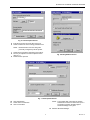
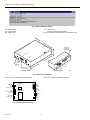
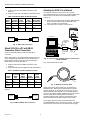
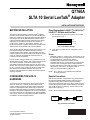
Q7760A
SLTA 10 Serial LonTalk® Adapter
INSTALLATION INSTRUCTIONS
BEFORE INSTALLATION
The SLTA-10 (Serial Interface or Serial LonTalk® Adapter)
provides communication between the LONWORKS® Bus and
either a PC serial port or approved modem using the SLTA-10
EIA-232 port. The SLTA-10 Q7760A2001 operates with the
Light Commercial Building Solution and the Excel 10 series
2000 family of controllers. It interfaces with LONSPEC™,
LONSTATION™, LONSTAT™, and E-Vision software. The
SLTA-10 Q7752A1011 operates with the Excel 10 VAV1 series
1000 controller and interfaces with LiveCare software.
There are two separate firmware images in the SLTA-10. The
two separate images have different link layer protocols,
network drivers, buffer capacity, and functionality. The two
modes of operation are SLTA-10 NSI mode and SLTA-10 MIP
mode. An externally accessible DIP switch at power-up
controls the mode of operation.
In SLTA-10 MIP mode, the SLTA-10 is a replacement for the
SLTA/2 Serial LonTalk® Adapter, with an improved form factor.
The network connector on the SLTA-10 is the orange
removable screw terminal instead of the RJ-45 used on the
SLTA/2. The SLTA-10 input power options include 9 to 30 Vac
or Vdc, or a 9 Vdc power supply. The SLTA-10 configuration
DIP switches are accessible externally. The SLTA-10
enclosure has been improved to allow wall mounting without
requiring a bracket.
CONFIGURING THE SLTA-10
HARDWARE
The SLTA-10 can be configured for direct communications
with a PC serial port, or remote communications with a
modem. Configure the SLTA-10 with its eight configuration
switches on the adapters switch block (S1). The SLTA-10
firmware reads these switches to configure or enable features.
Changes to the switch configurations do not occur until power
is cycled on the SLTA-10. The switches are read immediately
after a power reset. The configurations for Direct and Remote
are different, see their separate sections.
Direct Connections LONSPEC™ LONSTATION™
LONSTAT™ E-Vision and LiveCare
1.
Set the switches for direct connection to an PC serial
port as shown in Fig. 1.
ON/UP
1
2
3
4
5
6
7
8
OFF/DOWN
M17226
Fig. 1. Dip Switch Settings.
2.
Cycle power to enable the new configuration on the
SLTA-10.
Drivers
• NodeTalk: LONSPEC™, LONSTATION™, and LONSTAT™ use
the NodeTalk driver to manage SLTA-10 communications.
The NodeTalk driver is built into the software.
• LDVSLTA.SYS: E-Vision and LiveCare use the
LDVSLTA.SYS driver to manage SLTA-10 communication.
This driver has not changed, and is included with both
E-Vision and LiveCare. The Config.sys must be modified to
call this driver. Add a line to Config.sys similar to
Device=C:\E-Vision\ldvslta.sys /D1 /P1 /A.
NOTE: /Pn (n can be 1 or 2) determines the COM port.
/A means autobaud.
Remote Connections
Remote communication configurations vary greatly between
the Light Commercial Building Solution and the Excel 10
controllers. Both systems require an approved modem
connected to the EIA-232 port on the SLTA-10 with an SLTA
modem cable (Honeywell part number 32002517-001; DB-9
male to DB-25 male non-standard). The PC must have the
same modem. See Fig. 2.
NOTE: Do not select AutoBaud for remote connections.
MODEM
SLTA-10
DB25
MALE
SLTA-10 NULL
MODEM CABLE
DB9
MALE
M17231A
Fig. 2. Remote connection.
® U.S. Registered Trademark
Copyright © 2002 Honeywell International Inc.
All Rights Reserved
95-7511-4
Q7760A SLTA 10 SERIAL LONTALK® ADAPTER
Example:
DEVICE=C:\ LONWORKS\bin\LDVVDD.SYS /D1 /V”LonSLTA”.
Approved Modem: US Robotics 56K external V.90.
Modem Dip Switch Setting:
3, 4, and 8 down. All other switches up.
NOTE: To use the SLTALink Manager software the
REM out the E-Vision driver in the Config.sys
file.
LONSPEC™ and LONSTATION™
1.
2.
Configure the software tool for remote communication.
a. Open the project and the network.
b. Edit the network to include the phone number to
dial.
c. Click the File pull-down menu.
d. Select Communication Settings.
e. Choose the port where the modem is connected
(COM1 or COM2).
f. Choose the baud rate. Honeywell recommends
38400 bps.
g. Choose Modem connection type.
Configure the SLTA-10 for remote communications with
switch 2 (Remote Host), 6 and 8 (38.4K bps) in the up
position, as shown in Fig. 3.
ON/UP
1
2
3
4
5
6
7
8
Example:
REM DEVICE=C:\E-Vision\LDVSLTA.SYS /D1 /P1 /A.
The user must REM out the driver not being used when
switching between SLTALink Manager and SLTA-10 direct
connect operation. After changing the Config.sys file, the
computer must be rebooted for the new driver selection to be
active.
NOTE: Do not use a /Pn switch when using the
LDVVDD.SYS driver. The SLTALink Manager
automatically handles the COM selection.
Setting Switches on SLTA-10:
1. On SLTA-10 set switch 2 (Remote Host), 4 (NSI) and 6,
(19.2K bps) up. See Fig. 4.
OFF/DOWN
ON/UP
M17291A
Fig. 3. Dip Switch Settings.
3.
1
Enable new configuration by cycling power to SLTA-10.
4
5
6
7
8
OFF/DOWN
M17290
NOTE: Honeywell recommends a baud rate of
19.2K bps.
2.
E-Vision and LiveCare
Use SLTALink Manager software for remote communication
with E-Vision or LiveCare. The SLTALink Manager is currently
available free from the Echelon® web page.
DOWNLOADING SLTA-10 CONTROLLER SOFTWARE
1. Go to the site URL= http://www.echelon.com.
2. Click the self-extracting file SLTA.EXE on the Echelon
web page.
3. Select the following options to get the SLTA.EXE zip file.
• Services
• Developers Toolbox
4. Enter Username and password.
NOTE: To obtain username and password select GET
INSTANT ACCESS. There is no charge for a
username and password.
a. Select Drivers.
b. Select the following information: LONWORKS®
SLTA-10 NSI Mode Software and Microsoft®
Windows™ 95 and NT Drivers, release 1.04,
765K zip file.
Download the LONWORKS® SLTA-10 Software for
Windows NT and Windows 95.
3.
Lower the baud rate if problems occur. Set the balance
of switches down.
Connect LONWORKS® Bus to Network terminals.
CONNECTING THE MODEM
1. Connect the SLTA modem cable to approved modem
and the EIA 232 port on SLTA-10.
NOTE: The SLTA modem cable is a unique cable with
non-standard pin connections and grounding.
2.
3.
4.
Connect the phone line.
Power up the modem.
Cycle power on SLTA-10 to send the configuration
string to modem.
NOTE: The modem read and send LED flash when
the configuration string is received from the
SLTA-10. The SLTA-10 may need to be power
cycled more than once for the string to be sent.
ESTABLISHING SLTALINK MANAGER CONNECTION TO REMOTE
SITE.
1. Click SLTALink Manager.
2. From menu select Link then New.
3. Enter Name and select Remote for Link type.
(See Fig. 5).
4. Select Next to go to the next screen.
INSTALLING THE SLTALINK MANAGER.
1. Click SLTA.EXE.
LONWORKS® SLTA-10 installation starts automatically.
2. Follow instructions on the screen.
3. Select Yes to add DOS virtual device driver. The
installation adds a device driver to the Config.sys file.
95-7511—4
3
Fig. 4. Dip Switch Settings
NOTE: If problems are experienced due to a bad
connection, set switch 8 down to return to
19.2K bps and repeat step 3.
5.
2
2
Q7760A SLTA 10 SERIAL LONTALK® ADAPTER
Fig. 5. Link Description Screen.
5.
6.
Enter phone number of remote site (see Fig. 6).
Select modem from Connect Using pull down menu.
NOTE: Modems listed in Connect Using were
previously configured by Win 95 system.
7.
8.
9.
Select Next to accept the information and continue.
No entry is required in the Link Properties screen.
(See Fig. 7).
Select Finish to proceed.
Fig. 6. Dialing Address Screen.
Fig. 7. Link Properties Screen.
10.
11.
12.
Click Select/Action.
Select name of remote site.
Click Connect Now.
NOTE: The program dials out through the modem
selected and connects to remote site. Upon a
successful connection the status light in
SLTALink Manager turns green.
13.
3
Minimize SLTALink Manager.
95-7511—4
Q7760A SLTA 10 SERIAL LONTALK® ADAPTER
Fig. 8. SLTALink Manager Screen.
14.
15.
16.
Start E-Vision.
Open Project.
Select View.
Click On-line.
You have remote communications.
See Fig. 9 for SLTA-10 dimensions, front and back views.
17.
4(
10
DB9 FEMALE
CONNECTOR
(SERIAL I/O)
T
W
P
O
O
R
W
K
E
R
A
D
A
P
T
E
R
E
IA
-2
32
2)
E
®
0
N
N
LO
A
-1
HE
1-1
(32/4
)
A
S
T
E
IO
R
N
V
IC
E
S
LT
EC
U
R
EI
23
2
O
R
K
C
O
N
F
IG
A-
T
W
PO
N
E
W
LED
/4
5-1
SERVICE
REQUEST
SWITCH
(1
)
33
EC
HE
ER
LO
N®
LED
AC POWER
CONFIGURATION
DIP SWITCHES
DC POWER
FRONT VIEW
BACK VIEW
M17227A
Fig. 9. SLTA-10 front and back.
See Fig. 10 for an internal view of the SLTA-10.
(S2)
SERVICE
BUTTON
(DS1)
SERVICE LED
(S1)
CONFIGURATION
SWITCH
BLOCK
NEURON®
3150
CHIP
TRANSCEIVER
SECTION
See Table 1 for SLTA-10 interface functions.
(J5)
EIA-232
DATA
PORT
(DS2)
POWER
INDICATOR
LED
(J3)
POWER
INPUT
(J1)
NETWORK
CONNECTOR
(J2)
POWER
INPUT
M17219A
Fig. 10. Internal view of SLTA-10.
95-7511—4
4
Q7760A SLTA 10 SERIAL LONTALK® ADAPTER
Table 1. SLTA-10 Interface.
Interface
Function
Service Button S2
Pressing this switch grounds the service request pin on the Neuron® Chip inside the
SLTA-10. While this switch is pressed, the service LED should light to maximum intensity.
Service LED DS1
Yellow (LED) Indicates the Service Button is being pressed. If the Service button is not
being pressed, there are three possibilities: ON: The SLTA-10 firmware has detected an
unrecoverable error and/or the node has no application. Reboot the SLTA-10 from another
network interface on the channel. Blinking: Node is configured. OFF: Node is configured or
there is no power. Check LED.
EIA-232 Data Port J5
Connector for the EIA-232 serial I/O port. Standard DB9 female connection.
Network Connector 2 position J1
Orange connector for attachment to a twisted pair channel. The provided mating plug is
Weidmüller PN135606 (obtain locally).
Unregulated AC/DC power input 2 Black connector for the power input. The provided mating plug is Weidmüller PN125911
position J3
(obtain locally).
Unregulated AC/DC power input
barrel connector J2
Female 2.1 mm inside diameter and 5.5 mm outside diameter power input barrel connector.
Power indicator LED DS2
Green LED indicates presence of input power of the SLTA-10.
CABLING AND CONNECTIONS
Table 2. DCE Modem To SLTA-10 Connection
(DB-25 To DB-9).
EIA-232 devices are configured as either Data Circuitterminating Equipment (DCE), or as Data Terminal Equipment
(DTE). The SLTA-10 is a DCE device. A DCE device connects
to a DTE device unless a null modem cable is used. Using a
null modem cable, a DCE device connects to another DCE
device, and a DTE device can connect to another DTE device.
The standard configuration for a PC port is a DTE device. A
PC usually takes the terminal role in communications.
Modems should always be DCE devices. To connect an
SLTA-10 to a PC, connect one end of the serial cable to the
SLTA-10, and the other end of the cable to the PC serial port.
Connecting an SLTA-10 to a modem, requires a special null
modem cable.
NOTE: A standard off-the-shelf null modem cable does not
work with this configuration.
Honeywell offers the SLTA-10 Null Modem Cable (part
number 32002517-001) that is a DB-9 male to DB-25 male
null modem cable.
SLTA-10
(DCE) DB-9
Female
Modem Signal Cable DB-25 Cable DB-9
Name
Male
Male
RXD—Pin 3
Pin 3
Pin 3
TXD—Pin 3
TXD—Pin 2
Pin 2
Pin 2
RXD—Pin 2
DCD—Pin 8
Pin 8
Pin 4
DTR—Pin 4
DTR—Pin 20
RTS—Pin 4
Pin 20 and
Pin 4
Pin 6
DSR—Pin 6
GND—Pin 7
Pin 7
Pin 5
GND—Pin 5
See Fig. 11 to attach an SLTA-10 to a modem.
MODEM
SLTA-10
DB25
MALE
SLTA-10 NULL
MODEM CABLE
DB9
MALE
M17231A
Fig. 11. Attach SLTA-10 to a modem.
Attaching SLTA-10 to a Modem
CAUTION
Equipment Damage Hazard.
This product contains components that are sensitive to
static electricity. Before installing or removing the
network or serial cables, touch earth ground with your
hand to discharge any static electricity that may have
accumulated.
IMPORTANT
You must use the specific null modem cable
described in Table 2, to attach the SLTA-10 to a
modem.
Attach SLTA-10 to a PC with DB-9
Connectors (Direct Connection).
When connecting to a PC equipped with a DB-9 connector,
use a straight-through cable with one end terminating in a
DB-9 male connector and the other end terminating in a DB-9
female connector. See Table 3.
5
95-7511—4
Q7760A SLTA 10 SERIAL LONTALK® ADAPTER
Plug the male end of the DB-9 connector into the
SLTA-10.
Plug the female end of the DB-9 into the serial I/O port.
1.
2.
Table 3. PC DB-9 To SLTA-10 DB-9 Connection.
PC
Signal Connector
Name DB-9 Male
Cable
DB-9
Female
Cable
SLTA (DCE)
DB-9 Male DB-9 Female
RXD
Pin 3
Pin 3
Pin 2
Pin-2
TXD
Pin 3
Pin 3
Pin 3
Pin 3
Signal
Ground
Pin 5
Pin 5
Pin 5
Pin 5
Attaching the SLTA-10 to a Network
The network connector for the SLTA-10 is an orange,
two-conductor block type. Use the 2-pin conductor that comes
with the SLTA-10 to connect to the twisted-pair network.
See Fig. 14.
1.
2.
Connect the mini-phone plug end of the 32000180-009
SLTA Connector Cable to the LONWORKS® port on
either a controller or a wall module.
Connect the wire end of the to the SLTA-10.
Fig. 12 shows a DB-9 cable connecting a PC and an SLTA-10.
NOTEBOOK PC
PC (DTE)
SLTA-10
DB9
MALE
DB9
FEMALE
SHIELDED
INTERFACE
CABLE
M8649C
Fig. 12. DB-9 cable connection.
PC
SERIAL
PORT
Attach SLTA-10 to a PC with DB-25
Connectors (Direct Connection).
Q7760A
SLTA-10
SLTA-10
CONNECTOR
CABLE
Some PC serial I/O ports have a 25-pin male DB-25
connector.
E-BUS
PORT
M11943A
When connecting to a PC equipped with a DB-25 connector,
use a straight-through cable with one end terminating in a
DB-9 male connector and the other end terminating in a
DB-25 female connector. See Table 4.
Fig. 14. Connecting the portable operator terminal to the
LONWORKS® Bus.
Fig. 15 shows the SLTA-10 cable.
Plug the male end of the DB-9 connector into the
SLTA-10.
Plug the female end of the DB-25 into the serial I/O port.
1.
2.
Table 4. PC DB-25 To SLTA-10 DB-9 Connection.
Signal
Name
PC
Connector
DB-25
Male
Cable
DB-25
Female
Cable
DB-9 Male
SLTA
(DCE)
DB-9
Female
RXD
Pin 3
Pin 3
Pin 2
Pin-2
TXD
Pin 2
Pin 2
Pin 3
Pin 3
Signal
Ground
Pin 7
Pin 7
Pin 5
Pin 5
M17225
Fig. 15. SLTA-10 Connector Cable.
Fig. 13 shows a DB-25 to DB-9 cable connecting a PC and an
SLTA-10.
PC (DTE)
SLTA-10
DB25
FEMALE
DB9
MALE
M8650C
Power supply jack J3 provides screw terminals with a
provided Weidmüller input connector (PN 11261). This allows
the SLTA-10 to connect to a 9 to 30 Vac/Vdc power supply.
Fig. 13. DB-9 to DB-25 cable connection.
95-7511—4
Supply power to the SLTA-10 after it is connected to the
desired network. Table 5 has the specifications for power
inputs to the SLTA-10. The barrel connector input, J2, is a
standard female power plug with a 2.1 mm inside diameter
and a 5.5 mm outside diameter (LZR Electronics part number
HP114A, Radio Shack catalog number 274-1569, or
equivalent, obtain locally). Echelon recommends a surge
protector between the AC mains and the power supply.
6
Q7760A SLTA 10 SERIAL LONTALK® ADAPTER
Table 5. SLTA-10 Power Supply Requirements.
Power
Minimum
Nominal
IMPORTANT
Do not attempt to power an SLTA-10 from JP2 and
JP3 simultaneously. Mechanical insertion of a
connector into JP2 disables the input to JP3
(See Fig. 10).
Absolute
Maximum
Unregulated
DC
+9 Vdc
+12 Vdc
+30 Vdc
Unregulated
AC
9 Vac
24 Vac
30 Vac
ORDERING INFORMATION
When power is connected, the yellow service LED flashes
briefly and the green power indicator LED turns on. Once an
SLTA-10 is powered and configured, the service LED remains
off unless the service request switch is pressed.
Available Accessories:
Part number 32000180-009 Portable Operations Kit (includes
9 Vdc power supply and SLTA-10 connector cable).
Part number 32002517-001 Modem Installation Cable
(includes special null modem cable).
7
95-7511—4
Q7760A SLTA 10 SERIAL LONTALK® ADAPTER
LONWORKS®, LonTalk®, Neuron® are registered trademarks of Echelon® Corporation.
LONSPEC™, LONSTATION™, LONSTAT™ are trademarks of Echelon® Corporation.
Windows® is a registered trademark of Microsoft® Corporation.
By using this Honeywell literature, you agree that Honeywell will have no liability for any damages arising out of your
use or modification to, the literature. You will defend and indemnify Honeywell, its affiliates and subsidiaries, from and
against any liability, cost, or damages, including attorneys’ fees, arising out of, or resulting from, any modification to the
literature by you.
Automation and Control Solutions
ACS Control Products
Honeywell International Inc.
1985 Douglas Drive North
Golden Valley, MN 55422
Honeywell AG
Böblinger Straße 17
D-71101 Schönaich
Phone (49-7031) 637-01
Fax (49-7031) 637-493
95-7511—4
Honeywell Limited-Honeywell Limitée
35 Dynamic Drive
Scarborough, Ontario
M1V 4Z9
B.B. Rev. 12-02
Printed in U.S.A. on recycled
paper containing at least 10%
post-consumer paper fibers.
www.honeywell.com