1
SERVICE MANUAL
CODE: 00ZMXFXX1/S1E
DIGITAL FULL COLOR
MULTIFUNCTIONAL SYSTEM OPTION
FACSIMILE EXPANSION KIT
MODEL
MX-FXX1
CONTENTS
[1] PRODUCT OUTLINE . . . . . . . . . . . . . . . . . . . . . . . . . . . . . . . . . . . 1-1
[2] SPECIFICATIONS . . . . . . . . . . . . . . . . . . . . . . . . . . . . . . . . . . . . . . 2-1
[3] UNPACKING AND INSTALLATION
* For how to unpacking and installation, refer to the installation manual (00ZMX2700/I1E).
[4] EXTERNAL VIEWS AND INTERNAL STRUCTURES . . . . . . . . . . 4-1
[5] SIMULATIONS, FAX SOFTWARE SWITCH . . . . . . . . . . . . . . . . . . 5-1
[6] TROUBLE CODE . . . . . . . . . . . . . . . . . . . . . . . . . . . . . . . . . . . . . . 6-1
[7] MACHINE OPERATION . . . . . . . . . . . . . . . . . . . . . . . . . . . . . . . . . 7-1
[8] ELECTRICAL SECTION . . . . . . . . . . . . . . . . . . . . . . . . . . . . . . . . . 8-1
Parts marked with " " are important for maintaining the safety of the set. Be sure to replace these parts with
specified ones for maintaining the safety and performance of the set.
SHARP CORPORATION
This document has been published to be used
for after sales service only.
The contents are subject to change without notice.
CONTENTS
[1]
PRODUCT OUTLINE
[6]
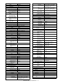
1. Trouble code list . . . . . . . . . . . . . . . . . . . 6-1
1. Configuration . . . . . . . . . . . . . . . . . . . . . .1-1
[2]
2. Details of trouble code . . . . . . . . . . . . . . 6-1
SPECIFICATIONS
3. Communication report codes . . . . . . . . . 6-2
1. FAX function . . . . . . . . . . . . . . . . . . . . . .2-1
4. Dial tone . . . . . . . . . . . . . . . . . . . . . . . . . 6-5
2. Image send function . . . . . . . . . . . . . . . .2-2
[3]
[4]
UNPACKING AND INSTALLATION
[7]
MACHINE OPERATION
* For how to unpacking and installation, refer to the
installation manual (00ZMX2700/I1E).
1. System settings list. . . . . . . . . . . . . . . . . 7-1
EXTERNAL VIEWS AND INTERNAL
STRUCTURES
3. Automatic reduction of the transmitted
image . . . . . . . . . . . . . . . . . . . . . . . . . . . 7-3
1. Operation panel . . . . . . . . . . . . . . . . . . . .4-1
4. Adding your sender information to
faxes (Own number sending) . . . . . . . . . 7-3
2. Transmittable original sizes . . . . . . . . . . 7-3
2. Touch panel of FAX mode . . . . . . . . . . . .4-1
[5]
TROUBLE CODE
SIMULATIONS, FAX SOFTWARE SWITCH
1. Simulation . . . . . . . . . . . . . . . . . . . . . . . .5-1
2. FAX software switch . . . . . . . . . . . . . . .5-19
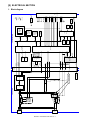
[8]
ELECTRICAL SECTION
1. Block diagram. . . . . . . . . . . . . . . . . . . . . 8-1
2. Actual wiring chart . . . . . . . . . . . . . . . . . 8-2
MXFXX1
[1]
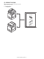
PRODUCT OUTLINE
Service Manual
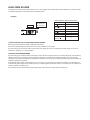
This unit provides the FAX function and the PC-FAX function when
installed to the following machines:
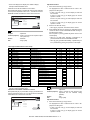
1. Configuration
Facsimile expansion kit
FAX memory
FAX-BOX unit
<MX-FXX1>
MX-FXX1 PRODUCT OUTLINE 1 – 1
G.
Memory
for Transmit/Receive
Service
Manual
[2] SPECIFICATIONS
MXFXX1
Standard
Memory extended
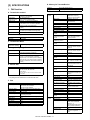
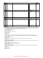
1. FAX function
H. Function
A. Transmission method
Transmission time
Compression/
expansion system
Modem speed
Resolution
Intercommunication
Communication line
ECM
Less than 3 sec (Super G3)
Less than 7 sec (G3 ECM)
MH, MR, MMR, JBIG
(Fixed to ECM for MMR or JBIG.)
33.6kbps → 2.4kbps automatic fallback
8 x 3.85 line/mm, 8 x 7.7 line/mm,
8.15.4 line/mm, 16 x 15.4 line/mm (Standard
memory is used for transmit/receive.)
G3/Super G3: Standard (V.34, V.17, V.33, V.29,
V.27ter)
General telephone line (PSTN), ISDN (When TA
is installed.) Private Branch Exchange (PBX)
Yes
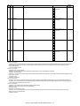
Transmit
function
On-hook
Quick online transmit
Direct transmit
Manual transmit
Auto re-call mode
Time indication function
Sequential broadcasting
function
F code interface
broadcasting indication
function
F code interface
broadcasting function
F code confidential send
function
Polling
1 line
Not provided
C. Transmission Mode
RSPF/OC
transmission switching
Calling function
PBX function
Memory transmit
B. Number of Support Line
Standard
Expansion
8M or 16M standard memory
8MB memory included in the package
Yes (Switching during the reading is not feasible)
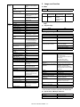
D. Image Quality/Image Process
Sequential polling function
Half tone reproduction
Exposure adjustment
FAX quality selection
Equivalent to 256 levels (Valid only when
monochrome document is scanned.)
Auto / Manual (5 steps)
Standard (8 x 3.85 lines/mm (203.2 x 97.8dpi))
Fine (8 x 7.7 lines/mm (203.2 x 195.6dpi))
Super Fine (8 x 15.4 lines/mm (203.2 x 391dpi))
Ultra Fine (16 x 15.4 lines/mm (406.4 x 391dpi))
Half-tone (Combination with normal character is
invalid.)
F-code polling
Bulletin board
F code bulletin board
function
Auto reduction transmit
Rotation transmit
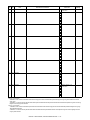
E. Record Size
Max. record width
Record size
Duplex transmit
Document transmit from OC
function
Long length original transmit
293mm
(AB series)
A3, B4, A4, A4R, B5, B5R, A5R
(Inch series)
11 x 17, 8.5 x 13, 8.5 x 14, 8.5 x 11, 8.5 x 11R,
8.5 x 5.5R
Mixed documents function
Zoom transmit
2 in 1 transmit
Card shot transmit
* If the document length exceeds A3 size, it is divided and printed.
* For printing the list, A5R and 8.5 x 5.5R cannot be used.
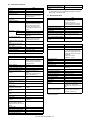
F. Dial
Manual dialing
Re-dialing
One-touch dialing
Group dialing
Program dialing
Chain dialing
Dial search
Quick search
LDAP search
Sub address
Password
Memory box registration
To be entered by 10-key, # key, * key
The previous 8 items (max.) can be saved, and
one of them can be selected.
One-touch call is available.
999 items including the group dialing items
999 items including the one-touch dialing items
Max. 48 items
Max. 64 digits including one-touch dialing, 10key dialing, and pause.
Alphabet order search, User index groups
Yes
Yes
Yes
Yes
Yes
Thin paper scan function
Edge erase transmit function
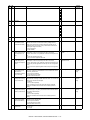
Receive
function
Job build
Page division transmit
Cover
Index
Transmit message adding
function
Auto receive
Manual receive
DRD call function
* LDAP: Lightweight Directory Access protocol
Memory receive
Transfer function
MX-FXX1 SPECIFICATIONS 2 – 1
Yes
Requires the frequency
setting for each destination.
Germany, France only
Yes (Definable destinations :
94 destinations)
Yes
Yes
Yes
Yes
Yes
Yes
Yes
Yes
Only one interface station
can be specified.
Yes
Yes
Yes
Even with another company
machine
Yes
Even with another company
machine
Yes
Yes
Yes
Yes
A3 → B4, A3 → A4, B4 → A4
Yes
Counterclockwise rotation of
90 degrees
Yes
Yes
Only when RSPF is used.
Transmission is enable up to
800mm.
Only when RSPF is used.
Yes
Yes
Only when transmitting from
OC
Available except for duplex
scan
Yes
Only for the fixed sizes
Yes
Yes
No
No
No
Yes
Yes
Distinctive Ring Detection
North America: Standard,
Pattern 1 – 5
Australia/New Zealand/Hong
Kong: ON/OFF (TEL/FAX)
Yes
Yes
Number of registration: 1
item
Receive
function
Specified receive function
Receive data print condition
function
Receive data staple setting/
Copy number setting
Rotation receive
Divided receive
Special
function
Duplex receive
F-code confidential receive
Print hold
Document Admin
Inbound Routing
Sender registration function
Sender print function
On-hook dialing function
Retransmit function
Pause function
Sound volume setting
function
Tone pulse select function
External phone connection
Memory remaining capacity
check function
Back up
Registered data read/write
function
Report/List
Destination check function
Broadcasting destination
display function
Transmit job change function
Save-energy function
Line monitor display function
FAST
Time adjust function
PC-FAX
Color mode
Sender registration function
Default destination setting
Unauthorized scan
prevention function
Filing-each-page function
Re-operation function
User account function
Counter function
Yes (Number of registration)
Rejection numbers: Max.50
items
Yes
2. Image send function
A. Mode
FAX
FAX to e-mail/FTP
B. System environment
Yes
Yes
Output by clockwise rotation
of 90 degrees
Yes
Divided print is not made in
duplex mode.
Yes
Yes
Yes
Yes
Yes
Yes
Yes
Yes
Yes
Yes
Pause time is 1 – 15 sec.
Yes
10PPS, 20PPS, Tone, Auto
(North America/Taiwan)
* For the other destinations,
set with the soft switch.
Yes
Yes
Only the integral part is
displayed.
Yes
Yes
Yes
Yes
Yes
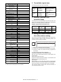
Fax
Copier memory
(Local memory)
768MB
(Standard)
Printer memory
(System Memory)
384MB (Standard)
(G model)
640MB (Standard)
(N model)
C. Image send function (Push send from the main
unit)
(1)
Support image
Mode
Compression method
(2)
No
Yes
Yes
Max. 200 items additionally
to the default
Yes
FAX
MH, MR, MMR, JBIG
Image processing
Mode
Original scanning color
Halftone reproduction
Density adjustment
FAX
B/W
Equivalent of 256 steps
Auto + 5 steps
Selection of image quality
Half tone (Black-white only) ON/OFF
Resolution (depends on file
format/transmission method)
Standard character (203.2 x 97.8dpi)
(half tone not allowed)
Fine (203.2 x 195.6dpi)
Super fine (203.2 x 391dpi)
Ultra fine (406.4 x 391dpi)
(3)
Specification of Addresses
Mode
Address specification
Yes
Yes
Yes
Yes
Facsimile Automated Service
Technology
Yes
Summer time ON/OFF
Yes
No
Yes
Number of registration: 1 for
standard sender, Max. 200
for other users
No
Yes
Data saving
destination
8MB
Number of One-touch address key
registration
Number of Group (1 key) address
registtation
Program
Direct entry of addresses
Chain dial
Resend
Shortcut for address selection
(quick key)
Sender name
Disable direct entry transmission
*2
Disable PC- Fax sending
Disable Internet Fax sending
FAX
Specification by one-touch/group/
direct address entry.
Entry from soft keyboard. (Scanner/
Internet Fax)
Entry from 10-key. (Fax)
Selection from LDAP server
Total (number of key): Maximum 999
Number of Group (1 key) address
registration : maximum 500
Number of Group key registration :
5000 (Total address number included
in /999 key)
48
Entry by 10-key, # key
Yes (pause key)
Call up nearest 8 addresses. *1
Use the 10-key to call up registered
numbers of addresses.
--(Selection from the list of default + 18
addresses as sender name)
Yes
Yes
Yes
*1: Except for FTP, Desktop, SMB, USB memory, Broadcast.
*2: When disabled, the address registration is not allowed either.
(4)
Specification of Multiple Addresses
Mode
Broadcast
Request of serial transmission
FAX
Yes (500 destinations)
Yes
* Broadcast transmission is allowed. (Monochrome only)
MX-FXX1 SPECIFICATIONS 2 – 2
(5)
Transmission function
Memory transmission
On-hook
Quick online transmission
Direct transmission
Automatically-reduced
transmission
Rotated transmission
Scaled transmission
Recall mode
Error
Busy
Long original transmission
Confidential transmission (Sharp
mode)
Relay broadcast transmission
(Sharp mode)
Large capacity original mode
Scanning of thin paper
Mixed originals feeder
Default date sender transmission
(6)
FAX
FAX
94 destinations in all
Yes
Yes
Yes
(Switching: Memory transmission ↔
Direct transmission)
Yes
Color toner print when black toner
runs out.
*1: This function saves all received data in memory and starts out
put after password entry. (Confidential reception is excluded.)
Setting only on the reciver side.
(7)
Report/list function
Image sending activity report
Yes
Yes
Enlargement/reduction is allowed
only from a fixed size to another.
Reduction may be done on the
receiver side with Fax/Internet Fax
sending.
Yes
Yes
Number/time to be set up through
system setup
Yes
Maximum of 800mm (single side
only/black-white 2 values only)
No
Transaction report
Address/phone number table
Group table
Program table
Memory box table (F code)
Communication original contents
print
List of rejected reception numbers
Table of control record for each
account
(8)
Time specification
Polling reception
Bulletin board transmission
Reception function
Automatic reception
Manual reception
Memory reception
Fixed size reduced reception
Specified size scaled reception
Rotated reception
Setting of received data print
condition
2-sided reception
2-in-1 reception
Automatic reduction setting upon
receiving A3
Automatic reduction setting upon
receiving letter
Reception from a specific number
not allowed. (To be rejected)
External phone connection
remote
Confidential reception (Sharp
mode)
Received data bypass output
Index printing
Transfer function upon disabling
of output.
Internet Fax/Fax to e-mail
(Transfer of Internet Fax/Fax
reception data to e-mail, inbound
routing)
Exit tray setting
Insertion of job separator sheet
Staple function of received data
Auto wake up print
Received data print hold *1
FAX
Yes
No
Switching from manual reception to
automatic reception. (Allowed only
for SEF and Japan)
Yes
Yes
No
Yes
Equal size print (partition not
allowed)
Equal size print (partition allowed)
Equal or reduced size print
Condition setting through system
setting
No
Yes
Yes
Specified numbers only (50 numbers
/20 digits)
Yes
No
Yes
No
Yes (1 receiver (of transfer)
registration)
Yes
FAX
Yes
Time-specified output
Output with memory full
* Maximum of 200 times including
both transmission and reception
Yes
Yes
Yes
Yes
Yes
Always print/Upon error/no print
Yes
No
Other Functions
No
Yes
Yes
Yes (Random + MIX)
Yes (ON only)
No
Cover sheet function
Transmission message
Sender print
Sender selection
Page number print
Date print
Polling protection function
Page partition transmission
Page connection
Confidential (receiver unit)
Relay broadcast instructions
Fax to e-mail (F code) *
Edge erase
Center erase
2 in 1
Card shot
Forward data transmission/
reception (Document Admin)
FAX
Yes
Yes
Yes
Up to 100 registrations allowed with
bulletin board, confidential and relay
broadcast all combined. (Free area :
1 registration)
Setting of the number of
transmission: 1/no limit.
No
No
Yes
Yes
Yes
Yes (Date can be expressed
alternatively)
Yes
Yes
No
Yes (F code method)
Yes (F code method)
Yes
Yes
Yes
Yes
Yes (Equivalent or enlargement up to
the paper width. The maximum
enlargement is not allowed to exceed
400%)
Yes
Data transmission by PC-Fax/PCInternet Fax is allowed, too.
* This function means that e-mail address setteing on F code relay
broadcast allowed.
Yes
No
Yes
Yes
Yes
MX-FXX1 SPECIFICATIONS 2 – 3
(9)
Transmission Method
Mode
Transmission time
Modem speed
Intercommunication
Communication line
ECM
(13) Telephone functions
FAX
2 seconds level (super G3/JBIG), 6
seconds level (G3 ECM)
Automatic fall-back : 33.6kbps →
2.4kbps
Super G3/G3
General membership telephone line
(PSTN), independent business line
(PBX), F net.
(R-key for PBX setting: SEGA/SEF)
Yes
(10) Record Size
Mode
Maximum record width
Record size
FAX
293mm
A3 – A5/11 x 17 – 5.5 x 8.5
(11) F code communication
Mode
Sub-address
Password
Mode
On-hook function
Hold
Setting of pause time
Telephone transmission during
power outage
Tone pulse switching
(14) Sound settings
Mode
On-hook sound
Sound volume for calling
Line monitor sound
Reception sound
FAX
Transmission success sound
FAX
Transmission and reception error
sound
Yes (20 digits)
Yes (20 digits)
(12) Registration-related settings
Mode
One-touch/group *1
E-mail
FTP
Desktop
SMB
FAX
Program
Number of memory boxes
Number of sender registration
Number of sender selection
registration
Registration of polling approval
number
Registration of Fax system
number (Sharp mode)
Registration of Fax polling
approval ID number (Sharp
mode)
Fax relay ID registration (Sharp
mode)
Quick key (short cut registration)
*2
Import/export of address book
Black list (for SEF)
999 destinations
Use of LDAP allowed
Up to 500 registered addresses for
each group dial.
Registered name in 18 full-size
character (36 half-size characters)
One-touch dial receiver number
registration: within 64 digits for
receiver number + sub-address +
passcode (including "/").
Registration of addresses (groups),
settings (density, image quality) and
special functions in one set is
allowed. (48 of them)
Registration of bulletin board/
confidential/relay broadcast is
allowed up to 100.
Registration name: 18 characters
1 (default) with 20 characters
Total: 18 registrations (20 characters)
(Sender selection: In addition to
default, 18 registrations allowed)
10 numbers/20 digits
FAX
Yes
No
Yes (1 – 15 seconds)
No (External telephone transmission
allowed)
10PPS, 20PPS, Tone, Auto (North
America/Taiwan)
* For the other destinations, set with
the soft switch.
Sound setting for end of original
reading (image send)
Item
Sound volume setting
Sound volume setting
Sound volume setting
Sound volume setting
Sound pattern
Sound volume setting
Sound pattern
Time setting for
communication ending
sound
Sound volume setting
Sound pattern
Time setting for
communication ending
sound
Sound volume setting
FAX
Yes *1
Yes *2
Yes *3
Yes *2
Yes *3
Yes *4
Yes *2
Yes *3
Yes *5
Yes *1
*1: Large/middle/small. Setup by system setting.
*2: Large/middle/small/no sound. Setup by system setting.
*3: PATTERN 1/2/3/4. Setup by system setting. Different sound
should be selectable for each of reception/transmission
success/transmission and reception error.
*4: Setup by system setting. 5 steps of 2.0 – 4.0 seconds.
*5: Setup by system setting. 2-steps setting for every 0.3 or
0.7 second.
(15) Others
Mode
PC-FAX
FAST
Network FAST
Distinctive ring detection
No
No
No
Yes (001 – 999)
Yes (By storage backup)
No
*1: Since scan/Internet Fax/Fax uses the common address book,
the number of addresses allowed for registration is the sum
total of all modes.
*2: Quick key is the function to select an address based on the
registered number of each address within the book for address
selection. Users should be able to select a quick key number.
MX-FXX1 SPECIFICATIONS 2 – 4
FAX
Yes
Yes (SEC only)
No
Setting for each destination
Manual
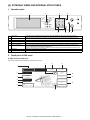
[4] EXTERNAL VIEWS AND INTERNAL Service
STRUCTURES
MXFXX1
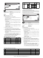
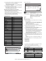
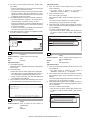
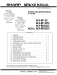
1. Operation panel
1
2
4
PRINT
READY
DATA
DOCUMENT
FILING
LINE
DATA
IMAGE SEND
COPY
3
SYSTEM
JOB STATUS SETTINGS
LOGOUT
5
1
Touch panel
2
3
4
5
6
[IMAGE SEND] key
Numeric keys
[C] key (clear key)
[∗] key
[CA] key (clear all key)
7
8
[STOP] key
[BLACK COPY START] key
6
7
8
A message or a key is displayed on the LCD screen. Touch the displayed key with your finger to perform various
operations. When the displayed key is touched, a sound is generated and the selected item is highlighted to confirm.
Press to switch to fax mode.
Use to enter fax numbers and numerical settings.
Use to clear a mistake when entering fax numbers and numerical settings. One digit is cleared each time you press the key.
This is used to produce tone signals when you are on a pulse dial line.
Use to cancel a transmission or programming operation. When this key is pressed, the operation is cancelled and you
return to the initial screen described on the following page.
This key is also used to cancel a resolution, paper size, or special function setting that was selected when sending a fax.
Press this key to stop scanning of an original.
Press to begin scanning an original for fax transmission.
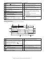
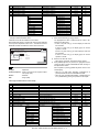
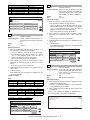
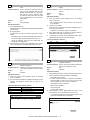
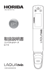
2. Touch panel of FAX mode
A. Base screen of FAX mode
This screen is used to select settings and operations in fax mode.
7
8
9
1
Ready to send.
Speaker
Resend
2
Fax
Mode Switch
3
Image
Settings
Sub Address
4
Memory TX
Special Modes
5
Direct TX
File
6
Address
Book
Auto Reception
Fax Memory:100%
Quick File
13
MX-FXX1 EXTERNAL VIEWS AND INTERNAL STRUCTURES 4 – 1
10
11
12
1
2
3
4
5
6
7
8
This shows various messages and the destinations that have been
entered.
The icon at the left
indicates fax mode.
[Mode Switch] key
Use these keys to change the mode of the image send function.
[Image Settings] key
Touch this key to select image settings (exposure, resolution, original
size, and two-sided original).
[Memory TX] key
This key is highlighted when a normal transmission (memory
transmission mode) is performed.
[Direct TX] key
Touch this key to send a fax by direct transmission.
This shows the currently selected fax reception mode and the
amount of free memory remaining.
key
Touch this key to use a speed dial number.
[Speaker] key
Touch this key to dial using the speaker.
When entering a fax number to be dialed, the key changes to the
[Pause] key. When entering a sub-address, the key changes to the
[Space] key.
9
[Resend] key
Touch this key to redial a fax number. When entering a fax number to be
dialed, this key changes to the [Next Address] key.
[Address Book] key
Touch this key to dial using a one-touch key or group key. The Address
Book screen appears when the key is touched.
[Sub Address] key
Touch this key to enter a sub-address and passcode for F-code
transmission.
Customized keys
These three keys can be changed to show any three settings or
functions that you like. The keys are changed in "Customize Key
Setting" in the system settings for Fax (administrator). Normally the
following keys appear:
• [Special Modes] key
Touch this key to use a convenient special mode.
• [File] key, [Quick File] key
Touch either key to use the File function or Quick File function of
document filing mode.
key
This key appears when one or more special modes have been selected.
Touch the key to display the selected special modes.
10
11
12
13
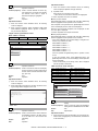
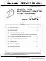
B. Address book screen
This screen is used to select a destination from the list of stored destinations.
3
4
5
CCC CCC
0123456789
1
2
To
Pause
Cc
1/1
3
4
5
6
6
Address Review
7
BBB BBB
CCC CCC
DDD DDD
Global
Address Search
8
EEE EEE
FFF FFF
Sub Address
9
ABCD
EFGHI
OPQRST UVWXYZ
JKLMN
10
2
Condition
Settings
AAA AAA
Frequent Use
1
Next Address
[To] key
Touch this key to enter the selected destination (one-touch key).
One-touch key display
This shows the one-touch keys of the destinations that have been stored
in the Address Book. This manual refers to keys in which destinations
and groups are stored as one touch keys.
Keys that have fax numbers stored are indicated by .
The number of one-touch keys displayed in one screen can be changed
in the system settings.
This shows the destination that has been selected.
[Cc] key
Not used in fax mode.
key
Touch this key to use a speed dial number.
[Condition Settings] key
Touch this key to select transmission settings and operations. When the
key is touched, the base screen appears.
Sort Address
11
7
8
[Address Review] key
Touch this key to view a list of the selected destinations.
[Global Address Search] key
Touch this key to obtain a fax number from a global address book (LDAP
server).
9
Page change keys
Use these keys to change pages when more one-touch keys have been
stored than can be displayed on one page.
10
Index tab
Touch this to change indexes of the one-touch key display.
[Sort Address] key
Touch this key to change the method of displaying the Address Book
screen.
11
MX-FXX1 EXTERNAL VIEWS AND INTERNAL STRUCTURES 4 – 2
Service Manual
[5] SIMULATIONS, FAX SOFTWARE SWITCH
MXFXX1
1. Simulation
(1)
A. General
a. Starting the simulation
There are the following simulation functions for grasping the
machine operating conditions, troubleshooting, early detection of
trouble causes, speedy setting and adjustments, and improvements in servicing.
* Entering the simulation mode
1)
Basic operation
Copy mode key ON → Program key ON → Asterisk (*) key
ON → CLEAR key ON → Asterisk (*) key ON → Ready for
input of a main code of simulation
1)
Various adjustments
2)
Entering a main code with the 10-key → START key ON
2)
Setting of the specifications and functions
3)
Entering a sub code with the 10-key → START key ON
3)
Canceling troubles
4)
Select an item with the scroll key and the item key.
4)
Operation check
5)
5)
Counters check, setting, clear
The machine enters the mode corresponding to the selected
item.
6)
Machine operating conditions (operation hysteresis), data
check, clear
Press START key or EXECUTE key to start the simulation
operation.
7)
Various (adjustments, setting, operation, counters, etc.) data
transfer
To cancel the current simulation mode or to change the main
code and the sub code, press the user setup key.
The operating procedures and displays depend on the form of the
operation panel of the machine.
* Canceling the simulation mode to return to the normal mode
1)
Press CA key.
(Note for the simulation mode)
Do not turn OFF the power switch on the operation panel when the
machine is in the simulation mode.
If the power switch should be turned OFF in the simulation mode, a
malfunction may be resulted. In this case, turn OFF/ON the main
power source.
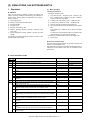
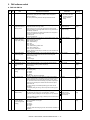
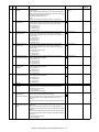
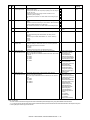
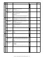
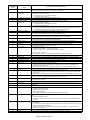
B. List of simulation codes
Code
Main Sub
13
-22
11
24
46
10
39
40
41
42
43
44
45
50
66
27
1
2
3
4
5
6
7
8
9
10
Function (Purpose)
Used to cancel the self-diag "U1" trouble.
Used to check the use frequency (send/receive) of FAX.
Used to clear the FAX counter.
Used to execute the image send sharpness adjustment.
Used to execute the FAX exposure adjustment. (Collective adjustment of all the
modes).
Used to execute the FAX exposure adjustment (Normal).
Used to execute the FAX exposure adjustment (Fine text).
Used to execute the FAX exposure adjustment (Super Fine).
Used to execute the FAX exposure adjustment (Ultra Fine).
Used to execute the FAX exposure level adjustment and the individual setting
(600DPI).
Used to adjust the image loss of scanned image in the FAX/Scanner mode.
Used to display the FAX-related soft SW on the LCD to allow changing the soft SW
while checking with the LCD.
Used to enter a country code and set the default value for the country code.
Used to execute the read/write check of EEPROM on the MODEM controller, SDRAM,
SRAM on the MFP controller, and flash ROM, and to display the results.
Used to send the selected signals to the line and the main unit speaker. (Send level:
max.)
Used to send the selected signal to the line and the main unit speaker. (Send level:
Soft SW setting) (For the kinds of send signals, refer to PART1 and PART2 of SIM6604.)
Used to print the confidential registration check table (BOX NO., BOX name,
passcode. (If there is no confidential registration, no print is made.)
Used to output all image data saved in the image memory. (Confidential data are also
outputted.)
Used to send the selected sound messages to the line and the speaker. (Send level:
Max.)
Used to send the selected sound message to the line and the speaker. (Send level:
max.)
* For details of sound messages, refer to the sound message table of SIM66-08.
Used to clear all image data saved in the FAX image memory. (The confidential data
are also cleared.)
Section
FAX
FAX
Purpose
FAX
MFP/FAX
Clear/cancel (Trouble etc.)
Adjustment/Setup/Operation
data check
Data clear
Adjustment
Adjustment
MFP/FAX
MFP/FAX
MFP/FAX
MFP/FAX
FAX
Adjustment
Adjustment
Adjustment
Adjustment
Adjustment
FAX/Scanner
Setting
Adjustment
FAX
Setting
Operation test/Check
FAX
FAX
Operation test/Check
FAX
Operation test/Check
FAX
Data output/Check
FAX
Data output/Check
FAX
Operation test/Check
FAX
Operation test/Check
FAX
Data clear
FAX
–
MX-FXX1 SIMULATIONS, FAX SOFTWARE SWITCH 5 – 1
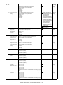
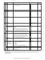
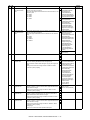
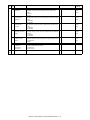
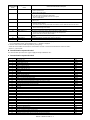
Code
Main Sub
66
11
Function (Purpose)
Section
Used to send the selected signal at 300bps to the line and the speaker. (Send level:
Max.)
Used to send the selected signal at 300bps to the line and the speaker. (Send level:
Soft SW setting)
* For the kings of send signals at 300bps, refer to SIM66-11, 300bps send signal table.
Used to register dial numbers for SIM66-14/15/16, Dial test. (Up to 20 digits can be
registered.)
Used to execute the dial pulse (10PPS) send test and to adjust the make time.
Used to execute the dial pulse (20PPS) send test and to adjust the make time.
Used to execute the DTFM signal send test and to adjust the send level.
Used to send the DTMF signal to the line and the speaker. (Send level: Max.)
Used to send the DTMF signal to the line and the speaker. (Send level: Soft SW
setting)
Used to write the telephone book data stored in HD into the FLASH ROM.
Used to write the telephone book data stored in the FLASH ROM into HD.
Used to print the selected items (various registration information, communication
management information, file management information, system error, protocol
monitor).
Used to set the handset sound volume. (This simulation can be executed even though
the handset setting is set to NO. When, however, the handset is not installed, the
sound volume cannot be checked.) (Japan model only)
Used to clear the FAST save data.
Used to register the FAX number for MODEM dial-in.
Used to register external telephone numbers for MODEM dial-in.
Used to initialize the telephone book data (the one-touch registration table, the FTP/
Desktop expansion table, the group expansion table, the program registration table,
the interface memory box table, the meta data, InboundRouting, and the
DocumentAdmin table).
Used to display the TEL/LIU status change, The display is highlighted by status
change.
Used to set ON/OFF the port for output to TEL/LIU.
Used to check the fixed data received from the line and to display the result.
Used to execute detection of various signals with the line connected and to display the
detection result. When a signal is detected, the display is highlighted.
Used to execute the send test and display the time required for sending image data in
the test. Used to execute send test and display. (Unit: ms)
Used to check send and receive data from the MODEM controller to the MFP controller
or the data line or the command line individually.
Used to check and change the destination setting saved in EEPROM of the FAX BOX.
Used to rewrite the program to power control installed in the FAX BOX.
Used to write the adjustment value into the power control installed in the FAX BOX.
12
13
14
15
16
17
18
19
20
21
22
24
25
26
29
30
31
32
33
34
36
39
42
43
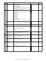
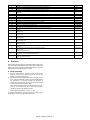
C. Details of simulation
Purpose
Operation test/Check
FAX
Operation test/Check
FAX
Setting
FAX
Adjustment
Adjustment
Adjustment
Operation test/Check
Operation test/Check
FAX
FAX
FAX
FAX
FAX
Backup
Backup
Check
FAX
FAX
FAX
Setting
FAX
Data clear
Setting
Setting
Clear
FAX
FAX
FAX
FAX
Operation test/Check
FAX
Setting
Operation test/Check
Operation test/Check
FAX
FAX
FAX
Operation test/Check
FAX
Operation test/Check
FAX
Setting
Setting
Setting
FAX
–
FAX
22
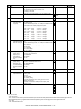
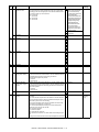
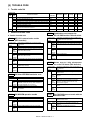
13
22-11
Purpose
13-Purpose
: Clear/cancel (Trouble etc.)
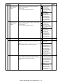
Function (Purpose) : Used to cancel the self-diag "U1" trouble.
Section
: FAX
Item
: Trouble
1)
Press [EXECUTE] button.
2)
Press [YES] button to execute cancellation of the trouble.
0
CLOSE
SIMULATION NO.13
U1 TROUBLE
CANCELLATION
ARE
YOU
SURE?
YES
Section
: FAX
Item
: Counter
Operation/Procedure
Operation/Procedure
TEST
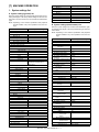
: Adjustment/Setup/Operation data check
Function (Purpose) : Used to check the use frequency (send/
receive) of FAX.
NO
EXECUTE
The values of the FAX send counter and the FAX receive counter
are displayed.
Press [COLOR] or [BLACK] button to print.
FAX OUTPUT
FAX OUTPUT_L2
FAX SEND
FAX RECEIVED
SEND IMAGES
SEND IMAGES_L2
SEND TIME
RECEIVED TIME
ACR SEND
FAX print quantity counter (for line 1)
FAX print quantity counter (for line 2)
FAX send counter
FAX receive counter
FAX send quantity counter (for line 1)
FAX send quantity counter (for line 2)
FAX send time
FAX receive time
Number of carrier prefix adding communications
MX-FXX1 SIMULATIONS, FAX SOFTWARE SWITCH 5 – 2
If there is any item under [↓], an active display is made and
item is shifted.
0
CLOSE
SIMULATION NO.22̆11
TEST
If there is no item over [↓], the display grays out and the
operation is invalid.
FAX COUNTER DISPLAY
FAX OUTPUT
㧦
00000000
FAX OUTPUT_L2 㧦 00000000
㧦 00000000
FAX SEND
FAX RECEIVED㧦 00000000
SEND IMAGES
SEND IMAGES_L2 㧦
00000000
SEND TIME
㧦
00000000:00:00
RECEIVED TIME
㧦
00000000:00:00
ACR SEND
㧦
00000000
㧦 00000000
2)
Enter the set value with 10-key.
3)
When [OK] button is pressed, the current entered value is
saved to EEPROM and RAM.
* Press [C] key to clear the entered values.
1/1
* When [↑], [↓] button, [COLOR], or [BLACK] key is pressed, the
current set values are saved to EEPROM and RAM.
<Set range and default value of each setup>
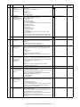
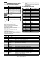
24
Item
Display
A
200 x 100[DPI]
OFF
200 x 200[DPI]
OFF
200 x 200[DPI] ON
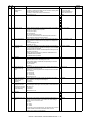
24-10
Purpose
B
: Data clear
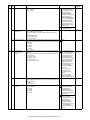
Function (Purpose) : Used to clear the FAX counter.
Section
: —
Item
: Counter
C
D
Operation/Procedure
Select the item to be cleared with the buttons on the touch
panel.
2)
Press [EXECUTE] button.
3)
Press [YES] button.
F
400 x 400[DPI]
OFF
400 x 400[DPI] ON
G
The target counter is cleared.
FAX OUTPUT
FAX OUTPUT_L2
FAX SEND
FAX RECEIVED
SEND IMAGES
SEND IMAGES_L2
SEND TIME
RECEIVED TIME
ACR SEND
200 x 400[DPI]
OFF
200 x 400[DPI] ON
E
1)
H
Print quantity counter (for line 1)
Print quantity counter (for line 2)
Send counter
FAX receive counter
FAX send quantity counter (for line 1)
FAX send quantity counter (for line 2)
FAX send time
FAX receive time
Number of carrier prefix attached communications
600 x 600[DPI]
OFF
600 x 600[DPI] ON
I
half tone
Set
range
0 to 2
Default
value
1
half tone
0 to 2
1
half tone
0 to 2
1
half tone
0 to 2
1
half tone
0 to 2
1
half tone
0 to 2
1
half tone
0 to 2
1
half tone
0 to 2
1
half tone
0 to 2
1
Content
200 x 100[DPI]
OFF
200 x 200[DPI]
OFF
200 x 200[DPI]
ON
200 x 400[DPI]
OFF
200 x 400[DPI]
ON
400 x 400[DPI]
OFF
400 x 400[DPI]
ON
600 x 600[DPI]
OFF
600 x 600[DPI]
ON
0
CLOSE
SIMULATION NO.46-39
TEST
IMAGE SEND SHARPNESS ADJUSTMENT
A:
0
㨇 0 㨪 2 㨉
A㧦 1
㧧 200
100
DPI
OFF
B㧦 1
㧧 200
200
DPI
OFF
C:
1
㧧 200
200
DPI
ON
D:
1
㧧 200
400
DPI
OFF
0
OK
CLOSE
SIMULATION NO.24̆10
TEST
FAX COUNTER DATA CLEAR
FAX OUTPUT
SEND IMAGES
FAX OUTPUT_L2
SEND IMAGES_L2
FAX SEND
FAX RECEIVED
SEND TIME
RECEIVED TIME
46-40
Purpose
ACR SEND
ARE
YOU
SURE?
YES
NO
EXECUTE
1/1
46
Section
: MFP/FAX
Item
: Image quality
Operation/Procedure
1)
Enter the set value with 10-key.
2)
When [EXECUTE] button is pressed, it is highlighted and the
current set value is saved to EEPROM and RAM. Printing for
the adjustment is started.
46-39
* When [C] key is pressed, the entered value is cleared.
Purpose
: Adjustment
Function (Purpose) : Used to execute the image send sharpness
adjustment.
Section
: FAX
Item
: Image quality
After completion of printing, [EXECUTE] button returns to the
normal display.
* When [OK] button, [COLOR], or [BLACK] key is pressed, the
data are saved to EEPROM and RAM.
Operation/Procedure
1)
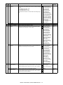
: Adjustment
Function (Purpose) : Used to execute the FAX exposure adjustment. (Collective adjustment of all the
modes).
Select the set item with [↑] and [↓] buttons.
The highlighted set value is switched and the value is displayed in the setting area.
* If there is any item over [↑], an active display is made and
item is shifted.
If there is no item over [↑], the display grays out and the
operation is invalid.
* When [C], [CA], [SYSTEM SETTINGS], or [EXECUTE] button is
pressed during printing, the operation is interrupted.
<Set range and default value of each setup>
Item
A
Display item &
Detail of display
EXPOSURELEVEL
(ALL)
MX-FXX1 SIMULATIONS, FAX SOFTWARE SWITCH 5 – 3
Content
Exposure data value
(Collective)
Set
range
1 to 99
Default
value
50
Item
0
TEST
G
ADJUSTMENT(FAX㧦ALL)
A㧦 50
A:
CLOSE
SIMULATION NO.46-40
EXPOSURE
㧧 EXPOSURE LEVEL(ALL)
50
㨇 1㨪 99㨉
EXECUTE
OK
Display item &
Detail of display
EXECUTE
AUTO
MODE
EXP1
EXP2
EXP3
EXP4
EXP5
Content
Print
mode
Auto
Exposure 1
Exposure 2
Exposure 3
Exposure 4
Exposure 5
Set
range
1
2
3
4
5
6
Default
value
1 (AUTO)
* Items G are displayed as "Display item: Detail of display."
Example: EXECUTE MODE: AUTO
<Reflection to item G after settlement of values>
46-41
Purpose
: Adjustment
Function (Purpose) : Used to execute the FAX exposure adjustment (Normal).
When [EXECUTE] key is pressed after changing and settlement of
exposure adjustment values A to F, the data are saved to EEPROM
and RAM and set to item G at the same time.
0
Section
: MFP/FAX
Item
: Image quality
TEST
Operation/Procedure
1)
EXPOSURE
Select the set item with [↑] and [↓] buttons.
A:
The highlighted set value is switched and the value is displayed in the setting area.
ADJUSTMENT(FAX㧦NORMAL)
50
㨇 1㨪
If there is no item over [↓], the display grays out and the operation is invalid.
* If there is any item over [↑], an active display is made and
item is shifted.
99㨉
A㧦 50
㧧 AUTO
B㧦 50
㧧 EXPOSURE1
C㧦 50
㧧
EXPOSURE2
D㧦 50
㧧
EXPOSURE3
EXECUTE
46-42
Purpose
If there is any item under [↓], an active display is made and
item is shifted.
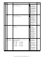
Function (Purpose) : Used to execute the FAX exposure adjustment (Fine text).
If there is no item over [↓], the display grays out and the
operation is invalid.
Section
: MFP/FAX
Item
: Image quality
: Adjustment
Enter the set value with 10-key.
Operation/Procedure
* When [C] key is pressed, the entered value is cleared.
1)
3)
When [EXECUTE] button is pressed, it is highlighted and the
current set value is saved to EEPROM and RAM. Printing for
the adjustment is started.
* If there is any item over [↑], an active display is made and
item is shifted.
If there is no item over [↑], the display grays out and the
operation is invalid.
* When [↑], [↓], [OK] button, [COLOR], or [BLACK] key is
pressed, the data are saved to EEPROM and RAM.
If there is any item under [↓], an active display is made and
item is shifted.
* When [C], [CA], [SYSTEM SETTINGS], or [EXECUTE] button is
pressed during printing, the operation is interrupted.
If there is no item over [↓], the display grays out and the
operation is invalid.
<Set range and default value of each setup>
Display item &
Detail of display
AUTO
EXPOSURE1
EXPOSURE2
EXPOSURE3
EXPOSURE4
EXPOSURE5
Content
Auto
Exposure 1
Exposure 2
Exposure 3
Exposure 4
Exposure 5
Set
range
1 to 99
1 to 99
1 to 99
1 to 99
1 to 99
1 to 99
Default
value
50
50
50
50
50
50
Select the set item with [↑] and [↓] buttons.
The highlighted set value is switched and the value is displayed in the setting area.
After completion of printing, [EXECUTE] button returns to the
normal display.
A
B
C
D
E
F
OK
If there is no item over [↑], the display grays out and the
operation is invalid.
2)
Item
CLOSE
SIMULATION NO.46-41
2)
Enter the set value with 10-key.
3)
When [EXECUTE] button is pressed, it is highlighted and the
current set value is saved to EEPROM and RAM. Printing for
the adjustment is started.
* When [C] key is pressed, the entered value is cleared.
After completion of printing, [EXECUTE] button returns to the
normal display.
* When [↑], [↓], [OK] button, [COLOR], or [BLACK] key is
pressed, the data are saved to EEPROM and RAM.
* When [C], [CA], [SYSTEM SETTINGS], or [EXECUTE] button is pressed during printing, the operation is interrupted.
<Set range and default value of each setup>
Item
A
B
C
D
E
F
G
Display item & Detail of display
AUTO
EXPOSURE1
EXPOSURE2
EXPOSURE3
EXPOSURE4
EXPOSURE5
AUTO H_TONE
Content
Fine/Auto
Fine/Exposure 1
Fine/Exposure 2
Fine/Exposure 3
Fine/Exposure 4
Fine/Exposure 5
Fine/Auto/Half tone
MX-FXX1 SIMULATIONS, FAX SOFTWARE SWITCH 5 – 4
Set range
1 to 99
1 to 99
1 to 99
1 to 99
1 to 99
1 to 99
1 to 99
Default value
50
50
50
50
50
50
50
Item
H
I
J
K
L
M
Display item & Detail of display
EXPOSURE1 H_TONE
EXPOSURE2 H_TONE
EXPOSURE3 H_TONE
EXPOSURE4 H_TONE
EXPOSURE5 H_TONE
EXECUTE MODE
AUTO
EXP1
EXP2
EXP3
EXP4
EXP5
AUTO H_TONE
EXP1 H_TONE
EXP2 H_TONE
EXP3 H_TONE
EXP4 H_TONE
EXP5 H_TONE
Content
Fine/Exposure 1/Half tone
Fine/Exposure 2/Half tone
Fine/Exposure 3/Half tone
Fine/Exposure 4/Half tone
Fine/Exposure 5/Half tone
Print mode
Fine/Auto
Fine/Exposure 1
Fine/Exposure 2
Fine/Exposure 3
Fine/Exposure 4
Fine/Exposure 5
Fine/Auto/Half tone
Fine/Exposure 1/Half tone
Fine/Exposure 2/Half tone
Fine/Exposure 3/Half tone
Fine/Exposure 4/Half tone
Fine/Exposure 5/Half tone
* Items M are displayed as "Display item : Detail of display."
1)
<Reflection to item M after settlement of the values>
* If there is any item over [↑], an active display is made and
item is shifted.
If there is no item over [↑], the display grays out and the
operation is invalid.
0
CLOSE
If there is any item under [↓], an active display is made and
item is shifted.
EXPOSURE ADJUSTMENT(FAX : FFINE)
A:
50
[ 1~ 99]
A : 50
AUTO
B : 50
EXPOSURE1
C : 50
EXPOSURE2
D : 50
EXPOSURE3
If there is no item over [↓], the display grays out and the
operation is invalid.
2)
Enter the set value with 10-key.
3)
When [EXECUTE] button is pressed, it is highlighted and the
current set value is saved to EEPROM and RAM. Printing for
the adjustment is started.
* When [C] key is pressed, the entered value is cleared.
EXECUTE
OK
46-43
Purpose
Select the set item with [↑] and [↓] buttons.
The highlighted set value is switched and the value is displayed in the setting area.
When [EXECUTE] button is pressed after changing and settlement
of the exposure adjustment values A to L, the data are saved to
EEPROM and RAM and reflected to item M at the same time.
SIMULATION NO.46-42
Default value
50
50
50
50
50
1 (AUTO)
Operation/Procedure
Example: EXECUTE MODE: AUTO
TEST
Set range
1 to 99
1 to 99
1 to 99
1 to 99
1 to 99
1 to 12
1
2
3
4
5
6
7
8
9
10
11
12
After completion of printing, [EXECUTE] button returns to the
normal display.
: Adjustment
Function (Purpose) : Used to execute the FAX exposure adjustment (Super Fine).
* When [↑], [↓], [OK] button, [COLOR], or [BLACK] key is
pressed, the data are saved to EEPROM and RAM.
Section
: MFP/FAX
Item
: Image quality
* When [C], [CA], [SYSTEM SETTINGS], or [EXECUTE] button is pressed during printing, the operation is interrupted.
<Set range and default value of each setup>
Item
A
B
C
D
E
F
G
H
I
J
K
L
M
Display item & Detail of display
AUTO
EXPOSURE1
EXPOSURE2
EXPOSURE3
EXPOSURE4
EXPOSURE5
AUTO H_TONE
EXPOSURE1 H_TONE
EXPOSURE2 H_TONE
EXPOSURE3 H_TONE
EXPOSURE4 H_TONE
EXPOSURE5 H_TONE
EXE-CUTE MODE
AUTO
EXP1
EXP2
EXP3
EXP4
EXP5
AUTO H_TONE
EXP1 H_TONE
EXP2 H_TONE
EXP3 H_TONE
EXP4 H_TONE
EXP5 H_TONE
Content
Super Fine/Auto
Super Fine/Exposure 1
Super Fine/Exposure 2
Super Fine/Exposure 3
Super Fine/Exposure 4
Super Fine/Exposure 5
Super Fine/Auto/Half tone
Super Fine/Exposure 1/Half tone
Super Fine/Exposure 2/Half tone
Super Fine/Exposure 3/Half tone
Super Fine/Exposure 4/Half tone
Super Fine/Exposure 5/Half tone
Print mode
Super Fine/Auto
Super Fine/Exposure 1
Super Fine/Exposure 2
Super Fine/Exposure 3
Super Fine/Exposure 4
Super Fine/Exposure 5
Super Fine/Auto/Half tone
Super Fine/Exposure 1/Half tone
Super Fine/Exposure 2/Half tone
Super Fine/Exposure 3/Half tone
Super Fine/Exposure 4/Half tone
Super Fine/Exposure 5/Half tone
MX-FXX1 SIMULATIONS, FAX SOFTWARE SWITCH 5 – 5
Set range
1 to 99
1 to 99
1 to 99
1 to 99
1 to 99
1 to 99
1 to 99
1 to 99
1 to 99
1 to 99
1 to 99
1 to 99
1 to 12
1
2
3
4
5
6
7
8
9
10
11
12
Default value
50
50
50
50
50
50
50
50
50
50
50
50
1 (AUTO)
* Items M are displayed as "Display item: Detail of display."
Example: EXECUTE MODE: AUTO
Operation/Procedure
1)
<Reflection to item M after settlement of the values>
Select the set item with [↑] and [↓] buttons.
The highlighted set value is switched and the value is displayed in the setting area.
When [EXECUTE] button is pressed after changing and settlement
of the exposure adjustment values A to L, the data are saved to
EEPROM and RAM and reflected to item M at the same time.
* If there is any item over [↑], an active display is made and
item is shifted.
If there is no item over [↑], the display grays out and the
operation is invalid.
0
TEST
CLOSE
SIMULATION NO.46-43
If there is any item under [↓], an active display is made and
item is shifted.
EXPOSURE ADJUSTMENT(FAX : SUPER FINE)
A : 50
A:
50
[ 1~ 99]
;
AUTO
B : 50
;
EXPOSURE1
C : 50
;
EXPOSURE2
D : 50
;
EXPOSURE3
If there is no item over [↓], the display grays out and the
operation is invalid.
EXECUTE
2)
Enter the set value with 10-key.
3)
When [EXECUTE] button is pressed, it is highlighted and the
current set value is saved to EEPROM and RAM. Printing for
the adjustment is started.
OK
* When [C] key is pressed, the entered value is cleared.
46-44
Purpose
: Adjustment
After completion of printing, [EXECUTE] button returns to the
normal display.
Function (Purpose) : Used to execute the FAX exposure adjustment (Ultra Fine).
Section
: MFP/FAX
Item
: Image quality
* When [↑], [↓], [OK] button, [COLOR], or [BLACK] key is
pressed, the data are saved to EEPROM and RAM.
* When [C], [CA], [SYSTEM SETTINGS], or [EXECUTE] button is pressed during printing, the operation is interrupted.
<Set range and default value of each setup>
Item
A
B
C
D
E
F
G
H
I
J
K
L
M
Display item & Detail of display
AUTO
EXPOSURE1
EXPOSURE2
EXPOSURE3
EXPOSURE4
EXPOSURE5
AUTO H_TONE
EXPOSURE1 H_TONE
EXPOSURE2 H_TONE
EXPOSURE3 H_TONE
EXPOSURE4 H_TONE
EXPOSURE5 H_TONE
EXECUTE MODE AUTO
EXP1
EXP2
EXP3
EXP4
EXP5
AUTO H_TONE
EXP1 H_TONE
EXP2 H_TONE
EXP3 H_TONE
EXP4 H_TONE
EXP5 H_TONE
Content
Ultra Fine/Auto
Ultra Fine/Exposure 1
Ultra Fine/Exposure 2
Ultra Fine/Exposure 3
Ultra Fine/Exposure 4
Ultra Fine/Exposure 5
Ultra Fine/Auto/Half tone
Ultra Fine/Exposure 1/Half tone
Ultra Fine/Exposure 2/Half tone
Ultra Fine/Exposure 3/Half tone
Ultra Fine/Exposure 4/Half tone
Ultra Fine/Exposure 5/Half tone
Print mode
Ultra Fine/Auto
Ultra Fine/Exposure 1
Ultra Fine/Exposure 2
Ultra Fine/Exposure 3
Ultra Fine/Exposure 4
Ultra Fine/Exposure 5
Ultra Fine/Auto/Half tone
Ultra Fine/Exposure 1/Half tone
Ultra Fine/Exposure 2/Half tone
Ultra Fine/Exposure 3/Half tone
Ultra Fine/Exposure 4/Half tone
Ultra Fine/Exposure 5/Half tone
* Items M are displayed as "Display item: Detail of display."
Example: EXECUTE MODE: AUTO
When [EXECUTE] key is pressed after changing and settlement of
exposure adjustment values A to L, the data are saved to EEPROM
and RAM and set to item M at the same time.
0
TEST
CLOSE
SIMULATION NO.46-44
EXPOSURE ADJUSTMENT(FAX : ULTRA FINE)
A:
[ 1~ 99]
50
A : 50
;
AUTO
B : 50
;
EXPOSURE1
C : 50
;
EXPOSURE2
D : 50
;
EXPOSURE3
Default value
50
50
50
50
50
50
50
50
50
50
50
50
1 (AUTO)
Writing
YES
YES
YES
YES
YES
YES
YES
YES
YES
YES
YES
YES
NO
46-45
Purpose
<Reflection to item M after settlement of values>
Default value
1 to 99
1 to 99
1 to 99
1 to 99
1 to 99
1 to 99
1 to 99
1 to 99
1 to 99
1 to 99
1 to 99
1 to 99
1 to 12
1
2
3
4
5
6
7
8
9
10
11
12
: Adjustment
Function (Purpose) : Used to execute the FAX exposure level
adjustment and the individual setting
(600DPI).
Section
: FAX
Item
: Image quality
Operation/Procedure
1)
Select the set item with [↑] and [↓] buttons.
The highlighted set value is switched and the value is displayed in the setting area.
EXECUTE
OK
* If there is any item over [↑], an active display is made and
item is shifted.
If there is no item over [↑], the display grays out and the
operation is invalid.
MX-FXX1 SIMULATIONS, FAX SOFTWARE SWITCH 5 – 6
If there is any item under [↓], an active display is made and
item is shifted.
3)
If there is no item over [↓], the display grays out and the
operation is invalid.
2)
When [EXECUTE] button is pressed, it is highlighted and the
current set value is saved to EEPROM and RAM. Printing for
the adjustment is started.
After completion of printing, [EXECUTE] button returns to the
normal display.
Enter the set value with 10-key.
* When [↑], [↓], [OK] button, [COLOR], or [BLACK] key is pressed,
the data are saved to EEPROM and RAM.
* When [C] key is pressed, the entered value is cleared.
* When [C], [CA], [SYSTEM SETTINGS], or [EXECUTE] button
is pressed during printing, the operation is interrupted.
<Set range and default value of each setup>
Item
A
B
C
D
E
F
G
H
I
J
K
L
M
Display item & Detail of display
AUTO
EXPOSURE1
EXPOSURE2
EXPOSURE3
EXPOSURE4
EXPOSURE5
AUTO H_TONE
EXPOSURE1 H_TONE
EXPOSURE2 H_TONE
EXPOSURE3 H_TONE
EXPOSURE4 H_TONE
EXPOSURE5 H_TONE
EXECUTE MODE AUTO
EXP1
EXP2
EXP3
EXP4
EXP5
AUTO H_TONE
EXP1 H_TONE
EXP2 H_TONE
EXP3 H_TONE
EXP4 H_TONE
EXP5 H_TONE
Content
600dpi/Auto
600dpi/Exposure 1
600dpi/Exposure 2
600dpi/Exposure 3
600dpi/Exposure 4
600dpi/Exposure 5
600dpi/Auto/Half tone
600dpi/Exposure 1/Half tone
600dpi/Exposure 2/Half tone
600dpi/Exposure 3/Half tone
600dpi/Exposure 4/Half tone
600dpi/Exposure 5/Half tone
Print mode
600dpi/Auto
600dpi/Exposure 1
600dpi/Exposure 2
600dpi/Exposure 3
600dpi/Exposure 4
600dpi/Exposure 5
600dpi/Auto/Half tone
600dpi/Exposure 1/Half tone
600dpi/Exposure 2/Half tone
600dpi/Exposure 3/Half tone
600dpi/Exposure 4/Half tone
600dpi/Exposure 5/Half tone
Example: EXECUTE MODE: AUTO
0
EXPOSURE
Use [FAX] button and [SCANNER] button to select the mode.
2)
Select the set item with [↑] and [↓] buttons.
The highlighted section of the set value is switched and displayed on the set setting area.
ADJUSTMENT(FAX㧦600DPI)
A㧦 50
A:
50
㨇 1㨪 99㨉
* If there is any item over [↑], an active display is made and
item is shifted.
㧧 AUTO
B㧦 50
㧧 EXPOSURE1
C㧦 50
㧧
EXPOSURE2
D㧦 50
㧧
EXPOSURE3
Writing
YES
YES
YES
YES
YES
YES
YES
YES
YES
YES
YES
YES
NO
1)
CLOSE
SIMULATION NO.46-45
Default value
50
50
50
50
50
50
50
50
50
50
50
50
1 (AUTO)
Operation/Procedure
* Items M are displayed as "Display item: Detail of display."
TEST
Set range
1 to 99
1 to 99
1 to 99
1 to 99
1 to 99
1 to 99
1 to 99
1 to 99
1 to 99
1 to 99
1 to 99
1 to 99
1 to 12
1
2
3
4
5
6
7
8
9
10
11
12
If there is no item over [↑], the display grays out and the
operation is invalid.
EXECUTE
If there is any item under [↓], an active display is made and
item is shifted.
OK
If there is no item over [↓], the display grays out and the
operation is invalid.
50
Enter the set value with 10-key.
4)
When [OK] button is pressed, the current entered value is
saved to EEPROM and RAM.
* Press [C] key to clear the entered values.
50-27
Purpose
3)
: Adjustment
Function (Purpose) : Used to adjust the image loss of scanned
image in the FAX/Scanner mode.
Section
: FAX/Scanner
Item
: Image quality
* When [↑], [↓] button, [COLOR], or [BLACK] key is pressed,
the data are saved to EEPROM and RAM.
* When [CLOSE] button is pressed, the display is shifted to the
copy basic screen of simulation.
* Copying can be performed also by pressing [COLOR]/[BLACK]
key.
MX-FXX1 SIMULATIONS, FAX SOFTWARE SWITCH 5 – 7
<Set range and default value of each setup>
FAX send
SCANNER
mode (FAX,
other than
COPY)
Item
A
B
C
D
E
F
G
H
I
A
B
C
D
E
F
G
H
I
Image loss
setting OC
Image loss
setting SPF
SIDE1
Image loss
setting SPF
SIDE2
Image loss
setting OC
Image loss
setting SPF
SIDE1
Image loss
setting
SPFSIDE2
Display item
LEAD_EDGE (OC)
FRONT_REAR (OC)
TRAIL_EDGE (OC)
LEAD_EDGE (SPF_SIDE1)
FRONT_REAR (SPF_SIDE1)
TRAIL_EDGE (SPF_SIDE1)
LEAD_EDGE (SPF_SIDE2)
FRONT_REAR (SPF_SIDE2)
TRAIL_EDGE (SPF_SIDE2)
LEAD_EDGE(OC)
FRONT_REAR(OC)
TRAIL_EDGE(OC)
LEAD_EDGE(SPF_SIDE1)
FRONT_REAR(SPF_SIDE1)
TRAIL_EDGE(SPF_SIDE1)
LEAD_EDGE(SPF_SIDE2)
FRONT_REAR(SPF_SIDE2)
TRAIL_EDGE(SPF_SIDE2)
* A to I: The greater the adjustment value is, the greater the image
loss is. 1step=0.1mm
Description
OC lead edge image loss setting
OC side image loss setting
OC rear edge image loss setting
Front surface lead edge image loss setting
Front surface side image loss setting
Front surface rear edge image loss setting
Back surface lead edge image loss setting
Back surface side image loss setting
Back surface rear edge image loss setting
5)
Default value
30 (3mm)
20 (2mm)
20 (2mm)
20 (2mm)
20 (2mm)
30 (3mm)
20 (2mm)
20 (2mm)
30 (3mm)
0 (0mm)
0 (0mm)
0 (0mm)
0 (0mm)
0 (0mm)
0 (0mm)
0 (0mm)
0 (0mm)
0 (0mm)
When [EXECUTE] button is pressed, it is highlighted and the
setting is saved.
After saving the setting, [EXECUTE] button returns to the normal display.
0
CLOSE
SIMULATION NO.50㧙27
TEST
Set range
0 to 100
0 to 100
0 to 100
0 to 100
0 to 100
0 to 100
0 to 100
0 to 100
0 to 100
0 to 100
0 to 100
0 to 100
0 to 100
0 to 100
0 to 100
0 to 100
0 to 100
0 to 100
SCANNER/FAX-SEND ALL EDGE ADJUSTMENT VALUE
A㧦
A:
30
㨇
0㨪
100 㨉
FAX
30
TEST
㧧 LEAD_EDGE(OC)
B㧦
20
㧧 FRONT_REAR(OC)
C㧦
20
㧧 TRAIL_EDGE(OC)
D㧦
30
㧧 LEAD_EDGE(SPF_SIDE1)
CLOSE
SIMLATION NO.66-01
FAX SOFT SW. SETTING.
SW No.
㧦
DATA
㧦
(SW No.2-170)
12345678
OK
SCANNER
EXECUTE
66
66-2
Purpose
66-1
Purpose
: Setting
Function (Purpose) : Used to display the FAX-related soft SW on
the LCD to allow changing the soft SW
while checking with the LCD.
Section
: FAX
Item
: Setting
Section
: FAX
Item
: Setting
Operation/Procedure
1)
1)
When the machine enters Simulation 66-01, the screen on the
right is displayed.
2)
When [SW NO] is entered with 10-key, "6" is displayed in the
column of [SW NO].
* (In this example, "6" is entered.)
* The country code shift screen is shown on the next page.
* The currently set country code is displayed in the column of
"PRESENT:".
2)
Enter the country code (8 digits) with 10-key([0]/[1]). The
entered country code is displayed in the column of "NEW:" and
[SET] key becomes active.
3)
When [SET] button is pressed after entering the country code,
[EXECUTE] button becomes active. The country code is displayed in the column of "PRESENT:", and the column of
"NEW:" is cleared.
* (The range of value to be entered is 2 to 170.)
* When [C] key is pressed, the entered value of [SW NO] is
cleared.
When [DATA] button is pressed, the data of soft SW No. 6 are
displayed.
* When [C] key is pressed, the column of “NEW:” is cleared.
* When [SW NO] button is pressed, the display returns to the
initial screen.
4)
* When [C] key is pressed, the display returns to the initial setting screen.
The data of soft SW can be changed with 10-key.
* When 10-key corresponding to the bit is pressed, the bit
data are displayed as follows:
[1] → [0]
[0] → [1]
* When [SW NO] button is pressed, the display returns to the
initial screen.
When the machine enters Simulation 66-02, the following
screen is displayed.
* When [DEST CODE] button is pressed, the display is shifted
to the country code list screen.
Operation/Procedure
3)
: Setting
Function (Purpose) : Used to enter a country code and set the
default value for the country code.
4)
When [EXECUTE] button is pressed, it is highlighted and
[YES] and [NO] buttons become active. The country name is
displayed on the tile line.
* When [NO] button is pressed, [EXECUTE] button returns to
the normal display and [YES] and [NO] buttons become
inactive.
MX-FXX1 SIMULATIONS, FAX SOFTWARE SWITCH 5 – 8
5)
When [YES] button is pressed, it is highlighted and the soft SW
corresponding to the country code is initialized.
Country code list screen
* During clearing the FAX-related soft SW, [EXECUTE] and
[YES] buttons are highlighted.
6)
TEST
After completion of initialization of the soft SW, [EXECUTE],
[YES], and [NO] buttons become inactive.
* When [CA] key is pressed after completion of initialization of
the soft SW, the whole machine is reset.
SWITCH
CLEAR
JAPAN
:00000000
U.S.A
:10110101 AUSTRALIA :00001001
U.K
:10110100
FRANCE
:00111101 GERMANY
SWEDEN
:10100101
NEWZELAND :01111110
SINGAPORE :10011100
Operation/Procedure (Shifting to the country page)
CLOSE
SIMULATION NO.66-02
FAX SOFT
TW
CHINA
:11111110 OTHER1
:00100110
:11111101
BACK
* When [DEST CODE] button is pressed on the initial screen, the
display is shifted to the country code list screen.
66-3
Use [↑] [↓] buttons to select the country select page.
When the table item is the top (last)item, [↑] [↓] buttons gray out.
When [↑] [↓] buttons gray out, they are disabled.
* Press [BACK] button to return to the entry screen.
<Country code list>
JAPAN
U.S.A.
AUSTRALIA
U.K.
FRANCE
GERMANY
SWEDEN
NEWZEALAND
CHINA
SINGAPORE
TW
OTHER1
OTHER2
OTHER3
FINLAND
NORWAY
DENMARK
NETHERLANDS
ITALY
SWITZERLAND
AUSTRIA
INDONESIA
THAILAND
MALAYSIA
INDIA
PHILIPPINES
HONGKONG
RUSSIA
SOUTHAFRICA
SPAIN
PORTUGUESE
LUXEMBURG
BELGIUM
CZECH
HUNGARY
GREECE
POLAND
:00000100
00000000
10110101
00001001
10110100
00111101
00000100
10100101
01111110
00100110
10011100
11111110
11111101
11111100
11111011
00111100
10000010
00110001
01111011
01011001
10100110
00001010
01010100
10101001
01101100
01010011
10001001
01010000
10111000
10011111
10100000
10001011
01101001
00001111
00101110
01010001
01000110
10001010
Purpose
: Operation test/Check
Function (Purpose) : Used to execute the read/write check of
EEPROM on the MODEM controller,
SDRAM, SRAM on the MFP controller, and
flash ROM, and to display the results.
Section
: FAX
Item
: Operation
Operation/Procedure
1)
When the machine enters Simulation 66-03, the following
screen is displayed.
* Use [↑] [↓] buttons to select the country select page. (The
highlighted section of the set value is switched and displayed on the set setting area.)
When [↑] [↓] buttons gray out, they are disabled.
2)
When the memory check item button is selected, the display is
shifted to the memory check screen.
3)
When [EXECUTE] button is pressed, it is highlighted and the
memory check of the selected item is started.
* Only one memory check item can be selected.
* When [EXECUTE] button is pressed again during memory
check, the operation is interrupted. (The display shows the
status immediately before pressing [EXECUTE] button.)
When [EXECUTE] button is pressed after interrupting the
operation, memory check is resumed.
4)
After completion of memory check, [EXECUTE] button returns
to the normal display and the result of memory check is displayed.
* For the memory which is not installed, [NO CHECK] is displayed.
* In the case of [REPEAT] check, the following display is made for
every execution.
CHECKING 0001
CHECKING 0002
CHECKING 0003
:
:
The number of times is displayed in 4-digit decimal numbers.
When the number exceeds 9999, it becomes 0000
Initial screen
Check is repeated until [EXECUTE] is pressed or [NG] occurs.
Memory check status
TEST
FAX
CLOSE
SIMULATION NO.66-02
SOFT
SW.CLEAR(WITH ADJUSTMENT
VALUE). CHINA
PRESENT㧦 00000000
NEW㧦
㧦
DEST CODE
ARE
SET
NO CHECK
CHECKING
OK
NG A##
No check
During checking
Check complete OK
Check complete NG
Error occurring address or data
line is displayed for each item.
Check item
YOU
SURE?
YES
NO
EXECUTE
1
Check memory item
All Memory Device Check (Once)
2
3
4
MFP SRAM (Once)
MFP SRAM (Repeat)
MFP FLASH + OP.FLASH (Once)
MX-FXX1 SIMULATIONS, FAX SOFTWARE SWITCH 5 – 9
Remark
All the items are checked
once.
Check only once
Repeat check
Check only once
Check memory item
MFP FLASH + OP.FLASH (Repeat)
MODEM EEPROM <1> (Once)
MODEM EEPROM <1> (Repeat)
MODEM SDRAM <1> (Once)
MODEM SDRAM<1>(Repeat)
5
6
7
8
9
Remark
Repeat check
Check only once in LINE1
Repeat check in LINE1
Check only once in LINE1
Repeat check in LINE1
The number in < > indicates the line.
TEST
SIMULATION NO.66-03
CLOSE
FAX PWB MEMORY CHECK
All Memory Device Check (once)
MFP SRAM (repeat)
66-5
Purpose
Section
: FAX
Item
: Operation
Operation/Procedure
1)
MFP SRAM (once)
MODEM EEPROM<1> (once)
MODEM EEPROM<1> (repeat)
MODEM SDRAM<1> (once)
When the machine enters Simulation 66-05, the following
screen is displayed. (Default, left upper selected)
* Use [↑] [↓] buttons to switch the send mode select page.
When the selected item is the top (last)item, [↑] [↓] buttons
gray out. (The highlighted section of the set value is
switched and displayed on the set setting area.)
MFP FLASH + OP.FLASH (once)
MFP FLASH + OP.FLASH (repeat)
: Operation test/Check
Function (Purpose) : Used to send the selected signal to the line
and the main unit speaker. (Send level: Soft
SW setting) (For the kinds of send signals,
refer to PART1 and PART2 of SIM66-04.)
When [↑] [↓] buttons gray out, they are disabled.
2)
When a button of a signal to be sent is selected, it is highlighted and the previously set button is shifted to the normal
display.
Function (Purpose) : Used to send the selected signals to the
line and the main unit speaker. (Send level:
max.)
3)
When [EXECUTE] button is pressed, it is highlighted and signals are sent.
Section
: FAX
4)
To end signal send:
Item
: Operation
66-4
Purpose
: Operation test/Check
* Only one signal to be sent can be selected.
* When [EXECUTE] button is pressed, it is highlighted and
signal send is interrupted.
Operation/Procedure
1)
When the machine enters Simulation 66-04, the screen on the
right is displayed. (Default, left upper selected.)
TEST
* Use [↑] [↓] buttons to switch the send mode select page.
When the selected item is the top (last)item, [↑] [↓] buttons
gray out. (The highlighted section of the set value is
switched and displayed on the set setting area.)
When [↑] [↓] buttons gray out, they are disabled.
2)
When a button of a signal to be sent is selected, it is highlighted and the previously set button is shifted to the normal
display.
3)
When [EXECUTE] button is pressed, it is highlighted and signals are sent.
NOSIGNAL
33.6 V34
31.2 V34
28.8 V34
26.4 V34
24.0 V34
21.6 V34
19.2 V34
16.8 V34
14.4 V34
12.0 V34
9.6 V34
7.2 V34
4.8 V34
2.4 V34
14.4 V33
EXECUTE
66-6
* Only one signal to be sent can be selected.
4)
CLOSE
SIMULATION NO.66-05
SIGNAL OUTPUT CHECK. (SOFT SW)
To end signal send:
When [EXECUTE] button is pressed, it is highlighted and signal send is interrupted.
Purpose
: Data output/Check
Function (Purpose) : Used to print the confidential registration
check table (BOX NO., BOX name, passcode. (If there is no confidential registration, no print is made.)
<Signal send table>
Section
: FAX
Page1
Item
: Data (Confidential passcode)
NOSIGNAL
26.4 V34
16.8 V34
7.2 V34
33.6 V34
24.0 V34
14.4 V34
4.8 V34
31.2 V34
21.6 V34
12.0 V34
2.4 V34
28.8 V34
19.2 V34
9.6 V34
14.4 V33
14.4 V17
9.6 V29
0.3 FLG
ANSam
12.0 V17
7.2 V29
CED 2100
RINGER
9.6 V17
4.8 V27t
CNG 1100
No RBT
Operation/Procedure
1)
* If there is no confidential registration, no print is made even
though [EXECUTE] key is pressed.
Page2
12.0 V33
7.2 V17
2.4 V27t
0.3 V21
When [EXECUTE] button is pressed, it is highlighted and the
confidential checkable is printed.
2)
After completion of printing, [EXECUTE] button returns to the
normal display.
* When [C], [CA], [SYSTEM SETTINGS], or [EXECUTE] key is
pressed during printing, the operation is interrupted.
Page3
DP MAKE
TEST
DP BRK
NO MSG
CLOSE
SIMULATION NO.66-04
SIGNAL OUTPUT CHECK. (LEVEL MAX)
NOSIGNAL
33.6 V34
31.2 V34
28.8 V34
26.4 V34
24.0 V34
21.6 V34
19.2 V34
16.8 V34
14.4 V34
12.0 V34
9.6 V34
7.2 V34
4.8 V34
2.4 V34
14.4 V33
EXECUTE
MX-FXX1 SIMULATIONS, FAX SOFTWARE SWITCH 5 – 10
66-7
66-9
Purpose
: Data output/Check
Purpose
Function (Purpose) : Used to output all image data saved in the
image memory. (Confidential data are also
outputted.)
Section
: FAX
Item
: Data (Image data)
* For details of sound messages, refer to
the sound message table of SIM66-08.
Operation/Procedure
1)
When [EXECUTE] button is pressed, it is highlighted and all
image data saved in the image memory are outputted.
* The confidential data are also outputted.
Section
: FAX
Item
: Operation
Operation/Procedure
1)
When the machine enters Simulation 66-09, the following
screen is displayed. (Default, left upper setting)
2)
When a button of a sound message to be sent is selected, it is
highlighted and the previously set button returns to the normal
display.
3)
When [EXECUTE] button is pressed, it is highlighted and a
sound message is sent.
4)
To end signal send:
After completion of printing, the image data are not cleared.
* If there is no image memory, no print is made though [EXECUTE] button is pressed.
2)
: Operation test/Check
Function (Purpose) : Used to send the selected sound message
to the line and the speaker. (Send level:
max.)
After completion of printing, [EXECUTE] button returns to the
normal display.
* When [C], [CA], [SYSTEM SETTINGS], or [EXECUTE] key is
pressed during printing, the operation is interrupted.
* Only one sound message to be sent can be selected.
When [EXECUTE] button is pressed, it is highlighted and signal send is interrupted.
CLOSE
TEST
SIMULATION NO.66-09
MESSAGE OUTPUT CHECK.(SOFT SW.)
NONE
PAUSE
MESSAGE1
MESSAGE2
MESSAGE3
MESSAGE4
MESSAGE5
MESSAGE6
ALARM
RINGER
EXT.TEL.RINGER
66-8
Purpose
EXECUTE
: Operation test/Check
Function (Purpose) : Used to send the selected sound messages to the line and the speaker. (Send
level: Max.)
Section
: FAX
Item
: Operation
66-10
Purpose
: Data clear
Operation/Procedure
Function (Purpose) : Used to clear all image data saved in the
FAX image memory. (The confidential data
are also cleared.)
1)
When the machine enters Simulation 66-08, the following
screen is displayed. (Default, left upper selected)
Section
: FAX
Item
: Clear (Image data)
When the sound message button to be sent is selected, it is
highlighted and the previously set button returns to the normal
display.
Operation/Procedure
2)
1)
[EXECUTE] button is highlighted and [YES] and [NO] buttons
become active.
* Only one sound message to be sent can be selected.
* When [EXECUTE] button is pressed, it is highlighted and a
sound message is sent.
2)
* When [NO] button is pressed, [EXECUTE] button returns to
the normal display and [YES] and [NO] buttons gray out.
<Sound message table>
MESSAGE3
(Message 3)
ALARM (Alarm)
PAUSE (Pause
melody)
MESSAGE4
(Message 4)
RINGER
(Ringing sound
(Speaker))
MESSAGE1
(Message 1)
MESSAGE5
(Massage 5)
EXT.TEL.RING
ER (External
telephone call)
MESSAGE2
(Message 2)
MESSAGE6
(Message 6)
Press [YES] button.
The image memory is cleared. [YES] button is highlighted.
* When [EXECUTE] button is pressed, it is returns to the normal display and sending a sound message is interrupted.
NONE (Mute)
Press [EXECUTE] button.
* During clearing the image memory, [EXECUTE] and [YES]
buttons are highlighted.
The image memory can be cleared even if there is no image
data.
3)
After completion of clearing, press [CA] key to reboot the
machine.
CLOSE
TEST
SIMULATION NO.66-08
MESSAGE OUTPUT CHECK. (LEVEL MAX)
NONE
PAUSE
MESSAGE1
MESSAGE2
MESSAGE3
MESSAGE4
MESSAGE5
MESSAGE6
ALARM
RINGER
EXT.TEL.RINGER
EXECUTE
MX-FXX1 SIMULATIONS, FAX SOFTWARE SWITCH 5 – 11
66-11
66-13
Purpose
: Operation test/Check
Purpose
: Setting
Function (Purpose) : Used to send the selected signal at 300bps
to the line and the speaker. (Send level:
Max.)
Function (Purpose) : Used to register dial numbers for SIM6614/15/16, Dial test. (Up to 20 digits can be
registered.)
Section
: FAX
Section
: FAX
Item
: Operation
Item
: Data (Registration)
Operation/Procedure
Operation/Procedure
1)
When the machine enters Simulation 66-11, the following
screen is displayed. (Default, left upper setting)
1)
2)
When a button of a sound message to be sent is selected, it is
highlighted and the previously set button returns to the normal
display.
When the machine enters Simulation 66-13, the following
screen is displayed.
* The number saved in the memory is displayed in the column
of [PRESENT:]. (If there is no data, [-------] is displayed.)
2)
Enter a number with 10-key.
* Only one sound message to be sent can be selected.
The entered number is displayed in the column of [NEW:].
3)
When [EXECUTE] button is pressed, it is highlighted and a
sound message is sent.
4)
To end signal send:
After entering 20 digits, 10-key is disabled (no response). Only
[C] key is enabled. (10-key [0] to [9], [*], [#], [C] key (back by
one digit))
When [EXECUTE] button is pressed, it is highlighted and signal send is interrupted.
3)
<300bps send signal table>
NO SIGNAL
010101
11111
00001
11110
When [SET] key is pressed after completion of entry, the
entered number is displayed (registered) in the column of
[PRESENT:]. The column of [NEW:] becomes blank.
* If the "NEW:" column is blank, SET is inactive. When a value
is entered to the "NEW:" column, it becomes active.
00000
CLOSE
TEST
SIMULATION NO.66-11
300bps SIGNAL OOUTPUT. (LEVEL MAX.)
NO SIGNAL
11111
010101
00001
11110
00000
EXECUTE
66-14
66-12
Purpose
Purpose
Function (Purpose) : Used to execute the dial pulse (10PPS)
send test and to adjust the make time.
: Operation test/Check
Function (Purpose) : Used to send the selected signal at 300bps
to the line and the speaker. (Send level:
Soft SW setting)
* For the kings of send signals at 300bps,
refer to SIM66-11, 300bps send signal
table.
Section
: FAX
Item
: Operation
: Adjustment
Section
: FAX
Item
: Operation
Operation/Procedure
1)
When the machine enters Simulation 66-14, the following
screen is displayed.
* Enter the make time (0 to 15) with 10-key and press [OK]
button, and the entered make time is temporality saved.
Operation/Procedure
1)
When the machine enters Simulation 66-12, the following
screen is displayed. (Default, left upper setting)
2)
When a button of a sound message to be sent is selected, it is
highlighted and the previously set button returns to the normal
display.
* Enter the make time (0 to 15) with 10-key and press [EXECUTE] button instead of [OK] button, and [EXECUTE] button is highlighted and the dial pulse is sent from the line in
the set make time.
2)
* The dial pulse in this example is up to 20 digits registered
with SIM66-13.
* Only one sound message to be sent can be selected.
3)
When [EXECUTE] button is pressed, it is highlighted and a
sound message is sent.
4)
To end signal send:
When [EXECUTE] button is pressed, it is highlighted and signal send is interrupted.
When [EXECUTE] button is pressed, it is highlighted and the
dial pulse is sent from the line in the set make time.
3)
To end the dial test, press [EXCUTE] button again. The button
returns to the normal display and the test is terminated.
Also when dialing the number is completed, [EXECUTE] button returns to the normal display and the test is terminated.
CLOSE
TEST
TEST
SIMULATION NO.66-12
DIAL TEST(10PPS)
300bps SIGNAL OOUTPUT. (SOFT SW.)
NO SIGNAL
11111
010101
00001
CLOSE
SIMULATION NO.66-14
11110
A㧦 4
00000
A:
㧧 MAKE TIME [+29ms]
4
㨇 0㨪 15㨉
EXECUTE
MX-FXX1 SIMULATIONS, FAX SOFTWARE SWITCH 5 – 12
EXECUTE
OK
66-15
Purpose
: Adjustment
CLOSE
SIMULATION NO.66-16
TEST
Function (Purpose) : Used to execute the dial pulse (20PPS)
send test and to adjust the make time.
DIAL TEST(DTMF)
Section
: FAX
A:
Item
: Operation
㨇 0㨪 15㨉
4
A㧦 4
㧧 HIGH(dB)
B㧦 4
㧧 HIGH-LOW
Operation/Procedure
1)
When the machine enters Simulation 66-15, the following
screen is displayed.
* Enter the make time (0 to 15) with 10-key and press [OK]
button, and the entered make time is temporality saved.
2)
3)
EXECUTE
OK
66-17
* Enter the make time (0 to 15) with 10-key and press [EXECUTE] button instead of [OK] button, and [EXECUTE] button is highlighted and the dial pulse is sent from the line in
the set make time.
Purpose
Section
: FAX
When [EXECUTE] button is pressed, it is highlighted and the
dial pulse is sent from the line in the set make time.
Item
: Operation
* The dial pulse in this example is up to 20 digits registered
with SIM66-13.
1)
When the machine enters Simulation 66-17, the following
screen is displayed. (Default, left upper selected)
2)
When a button of a send signal is selected, it is highlighted and
the previously set button returns to the normal display.
3)
When [EXECUTE] button is pressed, it is highlighted and signals are sent.
To end the dial test, press [EXCUTE] button again. The button
returns to the normal display and the test is terminated.
Operation/Procedure
Also when dialing the number is completed, [EXECUTE] button returns to the normal display and the test is terminated.
TEST
DIAL TEST(20PPS)
A㧦 4
A:
* Only one kind of signal to be sent can be selected.
* When another signal send button is pressed during sending
signals, the send signal can be changed.
CLOSE
SIMULATION NO.66-15
4)
㧧 MAKE TIME [+9ms]
: Operation test/Check
Function (Purpose) : Used to send the DTMF signal to the line
and the speaker. (Send level: Max.)
To stop signal sending:
When [EXECUTE] button is pressed, it returns to the normal
display and signal sending is interrupted.
4
㨇 0㨪 15㨉
EXECUTE
OK
SIMULATION NO.66-17
TEST
DTMF SIGNAL OUTPUT.(LEVEL MAX)
66-16
Purpose
: Adjustment
Function (Purpose) : Used to execute the DTFM signal send test
and to adjust the send level.
Section
: FAX
Item
: Operation
1
2
3
4
5
6
7
8
9
0
#
EXECUTE
Operation/Procedure
66-18
1)
Purpose
When the machine enters Simulation 66-16, the following
screen is displayed.
* Item A (High group frequency) and item B (High-Low group
frequency) are selected with [↑] [↓] buttons. When the
selected item is the top (last) item, [↑] [↓] buttons gray out.
(The highlighted section of the set value is switched and displayed on the set setting area.)
When [↑] [↓] buttons gray out, they are disabled.
* Enter the High group or High - Low group (0 to 15) with 10key and press [OK] button. The set sign send level is temporality saved.
* Enter the single send level (0 to 15) with 10-key and press
[EXECUTE] button instead of [OK] button, and [EXECUTE]
button is highlighted and the dial pulse is sent from the line
by the setting of high group or low group.
2)
3)
When [EXECUTE] button is pressed, it is highlighted and the
dial pulse signal is sent from the line by the setting of high/low
group of the signal send level.
To terminate the dial test, press [EXECUTE] button. The button
returns to the normal display and the test is terminated.
: Operation test/Check
Function (Purpose) : Used to send the DTMF signal to the line
and the speaker. (Send level: Soft SW setting)
Section
: FAX
Item
: Operation
Operation/Procedure
1)
When the machine enters Simulation 66-18, the following
screen is displayed.
2)
When a button of a send signal is selected, it is highlighted and
the previously set button returns to the normal display.
3)
When [EXECUTE] button is pressed, it is highlighted and signals are sent.
* When another signal send button is pressed during sending
signals, the send signal can be changed.
4)
To stop signal sending:
When [EXECUTE] button is pressed, it returns to the normal
display and signal sending is interrupted.
When dialing the dial number is completed, [EXECUTE] button
returns to the normal display and the test is terminated.
MX-FXX1 SIMULATIONS, FAX SOFTWARE SWITCH 5 – 13
SIMULATION NO.66-18
TEST
TEST
DTMF SIGNAL OUTPUT.(SOFT SW)
1
2
3
4
5
6
7
8
9
㧖
0
#
ARE
EXECUTE
66-19
: Backup
Purpose
Function (Purpose) : Used to write the telephone book data
stored in HD into the FLASH ROM.
Section
: FAX
Item
: Data
Operation/Procedure
Press [EXECUTE] button.
[EXECUTE] button is highlighted and [YES] and [NO] buttons
become active.
2)
Press [YES] button.
* When [NO] button is pressed, [EXECUTE] button returns to
the normal display and [YES] and [NO] buttons gray out.
After completion of memory writing, [EXECUTE] button returns
to the normal display and [YES] and [NO] buttons gray out.
CLOSE
SIMULATION NO.66-19
ADDRESS DATA BACK UP. (WRITE TO FLASH ROM)
: FAX
Item
NO
EXECUTE
: Data
Operation/Procedure
1)
When an item button to be printed is selected, it is highlighted
and the previously set button returns to the normal display.
(Default select: Left upper)
2)
Press [EXECUTE] button.
* Only one item can be selected.
[EXECUTE] button is highlighted and printing is started.
* During printing an item, [EXECUTE] and the print item button are highlighted.
3)
After completion of printing, [EXECUTE] button returns to the
normal display.
* When [C], [CA], [SYSTEM SETTINGS], or [EXECUTE] key is
pressed during printing, the operation is interrupted.
<FAX information print content table>
REGISTERED
FILE MANAGEMENT
PROTOCOL LINE 1
ARE
YOU
SURE?
YES
NO
MANAGEMENT
SYSTEM ERROR LINE 1
EXECUTE
TEST
66-20
Purpose
YES
: Check
Section
* During execution of backup, [EXECUTE] and [YES] buttons
are highlighted.
TEST
SURE?
Function (Purpose) : Used to print the selected items (various
registration information, communication
management information, file management
information, system error, protocol monitor).
The telephone book data stored in HD are written into the
FLASH ROM. [YES] button is highlighted.
3)
YOU
66-21
Purpose
1)
CLOSE
SIMULATION NO.66-20
ADDRESS DATA BACK UP. (READ FROM FLASH ROM)
SIMULATION NO.66-21
FAX INFORMATION PRINT OUT.
: Backup
Function (Purpose) : Used to write the telephone book data
stored in the FLASH ROM into HD.
Section
: FAX
Item
: Data
REGISTERED
MANAGEMENT
FILE MANAGEMENT
SYSTEM ERROR LINE 1
PROTOCOL LINE 1
EXECUTE
Operation/Procedure
1)
Press [EXECUTE] button.
[EXECUTE] button is highlighted and [YES] and [NO] buttons
become active.
2)
Press [YES] button.
The telephone book data stored in the FLASH ROM are written into HD. [YES] button is highlighted.
* When [NO] button is pressed, [EXECUTE] button returns to
the normal display and [YES] and [NO] buttons gray out.
3)
66-22
Purpose
: Setting
Function (Purpose) : Used to set the handset sound volume.
(This simulation can be executed even
though the handset setting is set to NO.
When, however, the handset is not
installed, the sound volume cannot be
checked.) (Japan model only)
* During execution of read/write, [EXECUTE] and [YES] buttons are highlighted.
Section
: FAX
After completion of memory writing, [EXECUTE] button returns
to the normal display and [YES] and [NO] buttons gray out.
Item
: Operation
Operation/Procedure
1)
When the machine enters the simulation, the number of the set
sound volume is displayed. (In this example, MIDDLE is set as
the default sound volume.)
MX-FXX1 SIMULATIONS, FAX SOFTWARE SWITCH 5 – 14
2)
Use 10-key to set the handset sound volume. (0: MIN 1:MIDDLE 2:MAX)
* Enter the sound volume (0 to 2) with 10-key and press [OK]
button. The set sound volume is saved.
* Enter the sound volume (0 to 2) with 10-key and press [EXECUTE] key instead of [OK] key. [EXECUTE] key is highlighted and the set sound volume is saved. The on-hold tone
is delivered in the set sound volume.
3)
Operation/Procedure
1)
* The stored number is displayed in the column of
"PRESENT:". (If there is no data, [-------] is displayed.)
2)
After entering 20 digits. 10-key is disabled. Only [C] key is
enabled.
* The sound message is outputted to the handset and an
external telephone. The speaker, however, is muted.
The entered number is displayed in the column of "NEW:".
(10-key [0] to [9], [*], [#], [C] key (back by one digit))
3)
* If, however, the handset is not installed, the sound volume
cannot be checked. Execution is possible.
4)
When [SET] button is pressed after completion of entering a
number, the entered umber is displayed (registered) in the column of "PREZENT:".
The column of "NEW:" becomes blank.
* When the column of "NEW:" is blank, [SET] becomes inactive. When a number is entered to "NEW:", [SET] becomes
active.
When [EXECUTE] button is pressed, it is highlighted and delivery of the on-hold tone is stopped.
TEST
Enter a number with 10-key.
Entry can be made up to 20 digits.
Press [EXECUTE] button to deliver the selected on-hold tone.
* Even during sending the on-hold tone ([EXECUTE] button is
highlighted), the sound volume can be changed by switching
the sound volume button.
When the machine enters Simulation 66-25, the following
screen is displayed.
CLOSE
SIMULATION NO.66-22
CLOSE
SIMULATION NO.66-25
TEST
HANDSET VOLUME SETTING
A
A:
1
M-D-IN FAX NUMBER SETTING. 0-9[0-9].*:[*]:#:[#]
(0:MIN 1:MIDDLE 2:MAX)
PRESENT :
1
0
2
EXECUTE
66-26
: Data clear
Function (Purpose) : Used to clear the FAST save data.
Section
: FAX
Item
: Data clear
Operation/Procedure
1)
2)
Purpose
: Setting
Function (Purpose) : Used to register external telephone numbers for MODEM dial-in.
Section
: FAX
Item
: Data (Registration)
Press [EXECUTE] button.
Operation/Procedure
[EXECUTE] button is highlighted and [YES] and [NO] buttons
become active.
1)
Press [YES] button.
* When [NO] button is pressed, [EXECUTE] button returns to
the normal display and [YES] and {NO} buttons gray out.
2)
Enter a number with 10-key. Entry can be made up to 20 digits.
After entering 20 digits. 10-key is disabled. Only [C] key is
enabled.
* During execution of the FAST save data clear, [EXECUTE]
and [YES] buttons are highlighted.
After completion of memory clear, [EXECUTE] button returns
to the normal display and [YES] and {NO} buttons gray out.
When the machine enters Simulation 66-26, the screen on the
right is displayed.
* The stored number is displayed in the column of
"PRESENT:". (If there data, [-------] is displayed.)
The FAST save data are cleared. [YES] button is highlighted.
3)
SET
OK
66-24
Purpose
---------------------
NEW :
The entered number is displayed in the column of "NEW:". (10key [0] to [9], [*], [#], [C] key (back by one digit))
3)
When [SET] button is pressed after completion of entering a
number, the entered umber is displayed (registered) in the column of "PRESENT:".
The column of "NEW:" becomes blank.
* When the column of "NEW:" is blank, [SET] becomes inactive. When a number is entered to "NEW:", [SET] becomes
active.
TEST
CLOSE
SIMULATION NO.66-26
M-D-IN EXTEL NUMBER SETTING. 0-9[0-9]*:[*]:#:[#]
PRESENT:
66-25
NEW:
Purpose
----------------㧦
: Setting
Function (Purpose) : Used to register the FAX number for
MODEM dial-in.
Section
: FAX
Item
: Data clear
MX-FXX1 SIMULATIONS, FAX SOFTWARE SWITCH 5 – 15
SET
66-29
66-31
Purpose
: Clear
Purpose
Function (Purpose) : Used to initialize the telephone book data
(the one-touch registration table, the FTP/
Desktop expansion table, the group expansion table, the program registration table,
the interface memory box table, the meta
data, InboundRouting, and the DocumentAdmin table).
Section
: FAX
Item
: Data (Initializing)
Section
: FAX
Item
: Operation
Operation/Procedure
1)
2)
Press [EXECUTE] button.
Press [YES] button.
The telephone book data area cleared. [YES] button is highlighted.
* When [NO] button is pressed, [EXECUTE] button returns to
the normal display and [YES] and [NO] buttons gray out.
* During the telephone book data clear, [EXECUTE] and
[YES] buttons are highlighted.
3)
Change the port setting.
When a port is set to ON, the port display is highlighted. Two or
more ports can be selected.
[EXECUTE] button is highlighted and [YES] and [NO] buttons
become active.
2)
When the machine enters Simulation 66-31, the following
screen is displayed.
* When starting execution of the simulation, the current setting is displayed.
Operation/Procedure
1)
: Setting
Function (Purpose) : Used to set ON/OFF the port for output to
TEL/LIU.
* At that time, the actual port output is not reflected.
3)
When [EXECUTE] button is pressed, the changed setting is
reflected to the port which outputs to TEL/LIU.
4)
To terminate the process, press [EXECUTE] button again.
[EXECUTE] button returns to the normal display.
<Port which outputs to TEL/LIU>
CION
MR
EC
S.
After completion of memory clear, [EXECUTE] button returns
to the normal display and [YES] and [NO] buttons gray out.
TEST
CLOSE
SIMULATION NO.66-31
TEL/LIU SETTING.
MR
CION
EC
S.
EXECUTE
66-32
Purpose
66-30
Purpose
: Operation test/Check
Function (Purpose) : Used to display the TEL/LIU status change,
The display is highlighted by status change.
Section
: FAX
Item
: Operation
Section
: FAX
Item
: Operation
Operation/Procedure
1)
Operation/Procedure
1)
When the machine enters Simulation 66-30, the following
screen is displayed.
2)
HS1, HS2, RHS, and EXHS are highlighted when the signal is
detected, and displayed normally when the signal is not
detected.
• The data received from the line is checked of the following
fixed data status for minutes, then if they are in accord with
“OK” is displayed on LCD, if not “NG” is displayed.
• The judgment is made in 2 minutes.
Receive speed: 300BPS
Receive data: 00H
Polarity inversion signal
Polarity inversion signal
Handset hook SW
External telephone hook SW
Judgment data: 100byte
2)
CLOSE
TEST
Press [EXECUTE] button to check the fixed data received from
the line. At that time, [EXECUTE] button is highlighted.
* Fixed data check procedure
<TEL/LIU status change item description>
HS1
HS2
RHS
EXHS
: Operation test/Check
Function (Purpose) : Used to check the fixed data received from
the line and to display the result.
After completion of check, [EXECUTE] button returns to the
normal display. The result is displayed as "OK" or "NG."
* To check the fixed data again, press [EXECUTE] button, and
check of the fixed data can be made again.
SIMULATION NO.66-30
TEL/LIU SENSOR CHECK
HS1
HS2
RHS
EXHS
TEST
CLOSE
SIMULATION NO.66-32
RECEIVED DATA CHECK
CHECKING
EXECUTE
MX-FXX1 SIMULATIONS, FAX SOFTWARE SWITCH 5 – 16
Operation/Procedure
66-33
1)
Function (Purpose) : Used to execute detection of various signals with the line connected and to display
the detection result. When a signal is
detected, the display is highlighted.
When the machine enters Simulation 66-36, the following
screen is displayed. (Default: left upper selected)
2)
Operation check
Section
: FAX
3.1. When "Operation check once" is selected:
Item
: Operation
● When (once) is selected:
Purpose
: Operation test/Check
Operation/Procedure
1)
When the machine enters Simulation 66-33, the following
screen is displayed.
2)
When a signal is detected, "FNET" and"BUSY TONE CNG
CED DTMF"are highlighted. When a signal is not detected,
they are normally displayed.
<Signal used for signal detection check>
When [EXECUTE] button is pressed under this state, [EXECUTE]
button is highlighted and the operation check is started.
After completion of the operation check, [EXECUTE] button returns
to the normal display and the check result is displayed.
When the check is normally completed, "OK" is displayed. In case
of an error, [NG" is displayed.
3.2. When "Operation check repeat" is selected:
When [EXECUTE] button is pressed under this state, [EXECUTE]
button is highlighted and the operation check is started.
FNET
* In the case of [Repeat] check, the title display is changed as follows for every execution of check.
(When "BT/CNG/CED/DTMF" is selected)
CNG
* When an item to be checked is selected, it is highlighted.
● When [repeat] is selected:
(When "FNET" is selected)
BUSY TONE
Select an item to be checked on the screen.
CED
DTMF
"MFP-MDMC I/F CHECK.- *"
"MFP-MDMC I/F CHECK.- **"
CLOSE
TEST
"MFP-MDMC I/F CHECK.- ***"
SIMULATION NO.66-33
"MFP-MDMC I/F CHECK.- ****"
SIGNAL DETECT CHECK.
"MFP-MDMC I/F CHECK.- *****"
FNET
Check is repeated until [EXECUTE] button is pressed or "NG"
occurs.
BT/CNG/CED/DTMF
To stop the operation check, press [EXECUTE] button, and
[EXEUTE] button returns to the normal display and the operation
check is terminated.
* When an abnormality occurs during check, "NG" is displayed
and the operation is terminated.
66-34
Purpose
: Operation test/Check
Function (Purpose) : Used to execute the send test and display
the time required for sending image data in
the test. Used to execute send test and display. (Unit: ms)
Section
: FAX
Item
: Operation
Operation/Procedure
1)
When the machine enters Simulation 66-34, the following
screen is displayed.
2)
When image data are actually sent, the time required for sending the image data is displayed on the LCD.
<MFP controller I/F check item table>
MFP ← MDMC (DATA once)
Data line Once
MFP ← MDMC (DATA repeat)
Data line Repeat
MFP ← MDMC (CMD once)
Command line Once
MFP ← MDMC (CMD repeat)
Command line Repeat
TEST
MFP → MDMC (DATA once)
Data line Once
MFP → MDMC (DATA repeat)
Data line Repeat
MFP → MDMC (CMD once)
Command line Once
MFP → MDMC (CMD repeat)
Command line Repeat
CLOSE
SIMULATION NO.6636
MFP-MDMC I/F CHECK.
MFP<-MDMC (DATA once)
MFP->MDMC (DATA once)
MFP<-MDMC(DATA repeat)
MFP->MDMC(DATA repeat)
MFP<-MDMC (CMD once)
MFP>MDMC (CMD once)
MFP<-MDMC (CMD repeat)
MFP->MDMC (CMD repeat)
EXECUTE
66-39
Purpose
: Setting
* #### : Time
Function (Purpose) : Used to check and change the destination
setting saved in EEPROM of the FAX BOX.
66-36
Section
: FAX
Purpose
Item
: Specifications
: Operation test/Check
Function (Purpose) : Used to check send and receive data from
the MODEM controller to the MFP controller or the data line or the command line
individually.
Section
: FAX
Item
: Operation
Operation/Procedure
1)
When the machine enters the simulation, the currently set destination button is highlighted. (In the default state, JAPAN is set
as the destination.)
MX-FXX1 SIMULATIONS, FAX SOFTWARE SWITCH 5 – 17
2)
Select a destination button to set the destination. (In this
example, USA/CANADA is selected.) The selected button is
highlighted and the previously selected button returns to the
normal display.
* When the destination button is changed, the new destination
setting is saved to EEPROM of the FAX BOX.
* When, however, there is no destination setting in EERPOM
of the FAX BOX, "NO DESTINATION" is displayed on the
title line and all the destination buttons are normally displayed.
66-43
Purpose
Section
: FAX
Item
: Setting
Operation/Procedure
1)
When the machine enters Simulation 66-43, the following
screen is displayed. (Default: left upper selected)
<Destination setting table>
JAPAN
CHINA
U.S.A/CANADA
ASIA&OTHERS
EUROPE
* Use [↑] [↓] buttons to select the select item of the power
control adjustment value. Selection is made in Item A to H.
AUSTRALIA
When the selected item is the top (last) item, [↑] [↓] buttons
gray out. (The highlighted section of the set value is
switched and the new value is displayed on the setting
area.)
CLOSE
TEST
SIMULATION NO.66-39
FAX DESTINATION SETUP
JAPAN
U.S,A/CANADA
CHINA
ASIA&OTHERS
When [↑] [↓] buttons gray out, they are disabled.
AUSTRALIA
EUROPE
: Setting
Function (Purpose) : Used to write the adjustment value into the
power control installed in the FAX BOX.
* Enter the power control adjustment value with 10-key and
press [OK] button ([↑] [↓] buttons). The set power control
adjustment value is saved to the primary memory area.
* The set data are saved in the primary memory area. Therefore, the setting is reflected only when [EXECUTE] button is
pressed to execute.
66-42
Purpose
* For the range of the power control adjustment value and
each value, refer to the table.
: Setting
Function (Purpose) : Used to rewrite the program to power control installed in the FAX BOX.
Section
: —
Item
: —
Operation/Procedure
1)
Press [EXECUTE] button.[EXECUTE] button is highlighted
and YES] and [NO] buttons become active.
2)
Press [YES] button.
The power control program is rewritten.
* During rewriting the power control program, [EXECUTE] and
[YES] buttons are highlighted.
* When [NO] button or [EXECUTE] button is pressed, [EXECUTE] button returns to the normal display, and [YES] and
[NO] buttons gray out.
3)
When rewriting of the power control program is normally completed, "OK" is displayed and [EXECUTE] button returns to the
normal display, and [YES] and [NO] buttons gray out.
* When rewriting of the power control program is failed, the
error message of "NG"is displayed and [EXECUTE] button
returns to the normal display, and [YES] and [NO] buttons
gray out.
2)
When [EXECUTE] key is pressed, it is highlighted and writing
to the power control is executed. When writing is normally
completed, "OK" is displayed. When it is failed, "NG" is displayed.
3)
After completion of writing, [EXECUTE] key returns to the normal display.
<Set range and default value of each set value>
Item
CI_LEVEL_JUDGE
CI_CYCLE_MIN
CI_CYCLE_MAX
CI_COUNT
POFF_LEVEL_JUDGE
EXHS_LEVEL_JUDGE
RHS_LEVEL_JUDGE
SON_TIMEOUT
A
B
C
D
E
F
G
H
TEST
A:
2
A:
2
CI_LEVEL_JUDGE
B:
10
CI_CYCLE_MIN
C : 110
CI_CYCLE_MAX
D:
CI_COUNT
3
EXECUTE
POWER CONTROL PROGRAM RELOAD
YOU
SURE?
CLOSE
SIMULATION NO.66-43
CLOSE
SIMULATION NO.66-42
ARE
Default value
2
10
110
3
15
10
2
20
PIC ADJUSTMENT VALUE WRITING.
㨇 2㨪 15 㨉
TEST
Set range
2 to 15
1 to 254
2 to 255
2 to 15
2 to 15
2 to 15
2 to 15
1 to 127
YES
NO
EXECUTE
MX-FXX1 SIMULATIONS, FAX SOFTWARE SWITCH 5 – 18
OK
2. FAX software switch
A. FAX Soft SW List
SW
No.
1
Bit
No.
1-8
2
1
4
SW selection and function
Country code
Control is performed according to the set country code.
The destination setting that is set in SIM66-2 as the image send
function is reflected.
The country code setting cannot be directly made from this SW.
Change from the
image send screen to
the copy screen
Setting to determine whether or not to automatically change from the
image send screen to the copy screen.
When changing over, if no keys are operated for 20 seconds after
pushing the final key in the image send mode, the copy mode will be
automatically switched to.
If there is no changeover, the machine will remain in the image send
mode and not switch to the copy mode.
"1": Change over
"0": Do not change over
Setting to determine the initial setting for image quality selection when
reading documents on the FAX.
"0000": Ordinary lettering
"0001": Small lettering
"0010": Fine
"0011": Very fine
"0101": Small lettering, medium tone
"0110": Fine, medium tone
"0111": Very fine, medium tone
"Ordinary lettering" (initial value) is reverted to if a value outside of the
setting range is set.
Setting to determine whether or not to make filed image quality valid
(initial setting for image quality selection when transmitting filed
document files by FAX)
"1": Apply
"0": Do not apply
2-5
Image quality priority
selection (standard
image quality setting)
6
Image quality setting
when saving (FAX)
7-8
3
Item
Not used
1
Received data printing
hold (FAX/Internet
FAX)
2-3
Tone/Pulse initial
setting (Dial call signal
setting)
4
Auto startup mode
5-8
Pause time setting
(between dials)
1-2
Speaker volume when
on-hook (Speaker
volume during DTMF
sending)
Setting to determine whether or not to store data received by FAX/
Internet FAX in the memory without outputting it.
"0": Do not hold
"1": Hold
This is set according to dial type.
"00": 10PPS (pulse)
"01": 20PPS
"10": TONE
"11": TONE
If "20pps" is set, adopt the initial TONE.
In the case where FAX or Internet FAX is received during nighttime
mode or simulated mode, if this setting is ON, the received document
will be outputted when the machine becomes able to output. When
OFF, the machine will receive the data by proxy without outputting the
document, but it will output the received document when the panel
power SW is ON.
"0": Setting (setting for automatically starting up the main unit and
outputting)
"1": Release (setting for storing in the memory without starting up the
main unit)
This sets the time per pause inputted during dialling.
The pause time can be set from 1 to 15 seconds in 1-second
increments by binary inputting N over the range of 0 to 15 (1 second x
N).
If a value outside the setting range (or "0000") is set, the initial value of
2 seconds is reverted to.
This sets speaker volume for when the on-hook button is pushed.
Volume is available in three types.
"00": Medium
"01": Small
"10": Medium
"11": Large
If a setting outside the setting range is set, the initial value of Medium is
reverted to.
Initial value
1
0
1
1
0
1
0
1
1
System
settings
North America
* For codes of the other
countries, refer to the
page of SIM 66-2
setting.
Change over
(North America)
Do not change over
(Other country)
Operation
settings
0
0
0
0
Ordinary lettering
Operation
settings
0
Do not apply.
Operation
settings
0
0
0
Do not hold
Operation
settings
1
0
TONE
FAX initial
setting
0
Setting
FAX initial
setting
0
0
1
0
"0010": 2 seconds
(Other country)
"0100": 4 seconds
(South Africa)
FAX initial
setting
1
0
Medium
FAX initial
setting
0
MX-FXX1 SIMULATIONS, FAX SOFTWARE SWITCH 5 – 19
SW
No.
4
Bit
No.
3-4
5-6
5
6
Item
Call sound volume
Line monitor volume
setting
7-8
Volume of the
transmission
completion sound
(Volume of the
successful
transmission sound)
1-2
Volume of the
communication error
completion sound.
(Volume of the
transmission and
reception error sound)
3-4
Volume of the
reception completion
sound (Volume of the
reception completion
sound)
5-6
Tone of the successful
transmission sound
7-8
Tone of the
transmission error
sound
1-2
Tone of the reception
sound
3-5
Setting of the
successful
transmission sound
time
6-8
Setting of the reception
sound time
SW selection and function
Irrespective of whether there is a handset, this sets the volume of the
call sound that is sounded when a signal arrives.
Volume is available in four types as follows.
"00": No sound
"01": Small
"10": Medium
"11": Large
Set the speaker volume during line monitoring.
Volume is available in four types as follows.
"00": No sound
"01": Small
"10": Medium
"11": Large
Set the volume of the completion sound outputted from the speaker
upon completion of FAX transmission.
Volume is available in four types as follows.
"00": No sound
"01": Small
"10": Medium
"11": Large
This sets the volume of the completion sound outputted from the
speaker upon completion of FAX communication error.
Volume is available in four types as follows.
"00": No sound
"01": Small
"10": Medium
"11": Large
This sets the volume of the completion sound outputted from the
speaker upon completion of FAX reception.
Volume is available in four types as follows.
"00": No sound
"01": Small
"10": Medium
"11": Large
This sets the tone sounded when transmission is successful.
"00": Pattern 1 (550Hz)
"01": Pattern 2 (750Hz)
"10": Pattern 3 (1000Hz)
"11": Pattern 4 (1700Hz)
This sets the tone sounded when there is a transmission error.
"00": Pattern 1 (550Hz)
"01": Pattern 2 (750Hz)
"10": Pattern 3 (1000Hz)
"11": Pattern 4 (1700Hz)
This sets the tone sounded upon completion of reception.
"00": Pattern 1 (550Hz)
"01": Pattern 2 (750Hz)
"10": Pattern 3 (1000Hz)
"11": Pattern 4 (1700Hz)
This sets the time the tone is sounded when transmission is successful.
"000": 2.0 seconds
"001": 2.5 seconds
"010": 3.0 seconds
"011": 3.5 seconds
"100": 4.0 seconds
The initial value is reverted to if a value outside of the setting range is
set.
This sets the time the tone is sounded upon completion of reception.
"000": 2.0 seconds
"001": 2.5 seconds
"010": 3.0 seconds
"011": 3.5 seconds
"100": 4.0 seconds
The initial value is reverted to if a value outside of the setting range is
set.
Initial value
System
settings
FAX initial
setting
1
0
Medium
1
0
Medium (North America/
Australia/Sweden/Finland/
Norway/Denmark/
Netherlands/Italy/
Switcherland/Austria/New
Zealand/China/Singapore/
Indonesia/Thailand/
Malaysia/India/Philippine/
Hong Kong/Taiwan/Middle
East/Slovakia/Other3/
South Africa/Spain/
Portuguese/Luxemburg/
Belgium/Czech/Hungary/
Greece/Poland)
No sound (U.K./France/
Germany/Rusia)
FAX initial
setting
Medium
FAX initial
setting
1
0
Medium
FAX initial
setting
1
0
Medium
FAX initial
setting
1
0
Pattern 3 (1000Hz)
FAX initial
setting
1
0
Pattern 3 (1000Hz)
FAX initial
setting
1
0
Pattern 3 (1000Hz)
FAX initial
setting
0
1
0
3.0 seconds
FAX initial
setting
0
1
0
3.0 seconds
FAX initial
setting
0
0
1
0
MX-FXX1 SIMULATIONS, FAX SOFTWARE SWITCH 5 – 20
SW
No.
7
Bit
No.
1
9
Setting of the time of
the transmission/
reception error sound
2-3
Communication results
sheet print settings (for
ordinary transmission)
<FAX only>
4-5
Setting of the
communication results
sheet printing (at times
of broadcast
transmission)
6-7
Communication results
sheet print setting
(when receiving)
<FAX only>
8
8
Item
1-2
Report output (when
receiving confidential
communications)
<FAX only>
Print document
contents when
transmitting (results
sheet)
<FAX only>
SW selection and function
Transmission error sound sounding interval
"0": Every 0.3 seconds
"1": Every 0.7 seconds
Sounding time and paper feeding time are the same.
This sets outputting of the communication results sheet following
transmission (excluding successive broadcast, successive polling and
relay broadcast transmission).
"00": Do not print
"01": Always print
"10": At times of transmission failure
The initial value is reverted to if a value outside of the setting range is
set.
This sets outputting of the communication results sheet at times of
successive broadcast, successive polling and relay broadcast
transmission.
"00": Do not print
"01": Always print
"10": Failed transmission address
The initial value is reverted to if a value outside of the setting range is
set.
This sets outputting of the communication results sheet for when
communications are received (excluding confidential communications).
"00": Do not print
"01": Always print
"10": At times of error
The initial value is reverted to if a value outside of the setting range is
set.
Setting to determine whether or not to output the communication results
sheet (receiving) when confidential communications are received.
"1": Print
"0": Do not print
This only functions when the communication results sheet print setting
(receiving) is set to be outputted.
Setting to determine whether or not to print part of the transmitted
document on the communication results sheet (transmission) when
FAX transmission error occurs.
"00": Do not print
"01": Always print
"10": At times of error
The initial value is reverted to if a value outside of the setting range is
set.
This functions when the communication results sheet print setting
(ordinary transmission) (broadcast transmission) is set to be outputted.
Setting to determine whether or not to automatically output the
communication record sheet when transmitted and received data on the
FAX/Internet FAX communication record sheet reach 200 entries.
"0": No (do not output)
"1": Yes (automatically output)
If the data are not outputted, then new data are written over the
previous data starting from the oldest of the 200 entries.
Trigger printing of 200 entries.
Set the hours part of the designated time (hours and minutes) for
outputting the communication record sheet.
Setting can be made over the range of 0 to 23 (hours) in 1-hour
increments by binary inputting. The initial value of 0 hour is reverted to if
a value outside of the setting range is set.
3
Automatic printing of
the record sheet when
memory is full.
4-8
Printing of the
communication record
sheet at a designated
time (hours)
1-6
Printing of the
communication record
sheet at a designated
time (minutes)
Set the minutes part of the designated time (hours and minutes) for
outputting the communication record sheet.
Setting can be made over the range of 0 to 59 (minutes) in 1-minute
increments by binary inputting. The initial value of 0 minute is reverted
to if a value outside of the setting range is set.
7
Printing of the
communication record
sheet at a designated
time
8
ECM (valid except
during V.34: reflected
in the V.21 DIS/DCS/
DTC)
Setting to determine whether or not to output the communication record
sheet at a designated time.
"1": Output the communication record sheet at a designated time
"0": Do not output the communication record sheet at a designated
time. Even if designated time printing is set, do not output when the
designated time coincides with the nighttime FAX mode.
Setting to determine whether or not to execute the error re-send mode.
However, this is only valid when communication is other than V.34.
"1": No. Set with no ECM function.
"0": Yes. Set with ECM function.
ECM is on during communication in the V.34 mode.
Initial value
System
settings
FAX initial
setting
0
Every 0.3 seconds
1
0
At times of transmission
failure
FAX initial
setting
0
1
Always print
FAX initial
setting
0
0
Do not print
FAX initial
setting
0
Print
FAX initial
setting
1
0
At times of error
FAX initial
setting
0
No
FAX initial
setting
0
0
0
0
0
0
0
0
0
0
0
0
0 hour
FAX initial
setting
0 minute
FAX initial
setting
Do not output
FAX initial
setting
0
Yes
FAX initial
setting
MX-FXX1 SIMULATIONS, FAX SOFTWARE SWITCH 5 – 21
SW
No.
10
Bit
No.
1-8
11
1-4
Distinctive ring (DRD
setting)
5-8
Not used
1-2
Not used
3-4
PBX setting
5-8
ID (number) setting
<Input the 1st digit
when dial inputting and
dialing>
1-4
ID (number) setting 2
<Input the 2nd digit
when dial inputting and
dialing>
5-8
ID (number) setting 3
<Input the 3rd digit
when dial inputting and
dialing>
12
13
14
1
2-8
Item
Remote changeover
number setting
External telephone
connection
Not used
SW selection and function
Set by binary inputting the number for receiving remote changeover
from external telephones.
However, the remote changeover number is "XX*" with * fixed.
Adopt * when "A" is inputted.
Adopt # when "B" is inputted.
For bits 1-4, fix the upper digit of the remote changeover number. (0-F)
For bits 5-8, fix the second lowest digit of the remote changeover
number. (0-F)
When C-F are set, the initial value is reverted to.
Setting to determine whether or not to execute FAX arrival call by the
distinctive ring.
Even if a call signal other than the set pattern is detected, there will be
no automatic arrival call.
"0000": OFF
"0001": STANDARD
"1000": Pattern 1
"0100": Pattern 2
"1100": Pattern 3
"0010": Pattern 4
"1010": Pattern 5
"0110": ON (Australia)
"1110": ON (New Zealand)
"1001": ON (Hong Kong)
When contents other than the above are set, the initial value is reverted
to.
Setting to determine whether or not to send out ID or Flash before
dialing.
Functions only in Germany and France.
In other countries, this setting is fixed to "OFF".
"00": OFF
"01": Flash
"10": ID
The setting other than the above would be granted as the default.
Conduct ID No. setting when the PBX function is valid.
Valid when ID is set using SW12-3, 12-4.
The initial value of 0 is reverted to if a value outside of the setting range
(10-15) is set.
Conduct ID No. setting when the PBX function is valid.
Valid when ID is set using SW12-3, 12-4.
When 10-12, 14, 15 are designated, do not use numbers with those
digits.
"-" when 13 is set.
Conduct ID No. setting when the PBX function is valid.
Valid when ID is set using SW12-3, 12-4.
When 10-12, 14, 15 are designated, do not use numbers with those
digits.
"-" when 13 is set.
Setting to determine whether or not to use an external telephone.
If "Yes" is not set using this switch, an external telephone cannot be
used.
"0": No (invalid)
"1": Yes (valid)
The user cannot set without an external telephone.
Initial value
System
settings
FAX initial
setting
0
1
0
1
1
0
1
0
5*
0
0
0
0
OFF
FAX initial
setting
No (invalid)
FAX initial
setting
0
1
1
0
0
0
0
0
0
0
0
0
1
1
0
1
FAX initial
setting
FAX initial
setting
1
1
0
1
1
0
1
0
0
0
0
0
MX-FXX1 SIMULATIONS, FAX SOFTWARE SWITCH 5 – 22
FAX initial
setting
Yes
FAX initial
setting
SW
No.
15
Bit
No.
1-8
Signal sending level
16
1-8
Not used
17
1
Automatic reduced
transmission
2
Rotated transmission
selection (A4 → A4R)
3
Rotated transmission
selection (B5R → B5)
4
Rotated transmission
selection (A5R → A5)
5
Rotated transmission
selection
(8.5 x 11 → 8.5 x 11R)
6
Rotated transmission
selection
(16K → 16KR)
7
Rotated transmission
selection (5.5 x 8.5R →
5.5 x 8.5)
Item
SW selection and function
Set the level adjustment for sending signals from the modem. Setting
can be made over the range of 0 to 26 in 1dBm increments by binary
inputting.
Since the maximum level differs according to country, if a value above
the maximum level is set, the maximum value for the present country
code will be adopted.
Initial value
0
0
0
0
1
0
1
0
0
"00001010": -10dBm
(North America/China/
Singapore/Thailand/
Malaysia/Philippine/Hong
Kong/Middle East/Other3)
"00001001": -9dBm (U.K./
France/Germany/Sweden/
Finland/Norway/Denmark/
Netherlands/Italy/
Switcherland/Austria/
Indonesia/Slovakia/South
Africa/Spain/Portuguese/
Luxemburg/Belgium/
Czech/Hungary/Greece/
Poland)
"00001011": -11dBm
(Australia/New Zealand/
India/Taiwan/Rusia)
Refer to "SW16, 1-8 Initial
value"
Transmit in reduced size.
0
Rotate
FAX
transmission
setting
0
Rotate
FAX
transmission
setting
0
Rotate
FAX
transmission
setting
0
Rotate
FAX
transmission
setting
0
Rotate
FAX
transmission
setting
0
Rotate
FAX
transmission
setting
0
In cases where the transmitted document size (width) is larger than the
FAX paper size (width) of the other party’s machine, this setting
determines whether to reduce the transmitted document or to cut off
both edges.
"0": Transmit in reduced size
"1": Do not transmit in reduced size
Rotated transmission or not depending on orientation of the document.
When transmitting A4 document, this setting determines whether to
transmit as A3 width (A4) or to rotate the read image and transmit as A4
width (A4R).
"0": Rotate
"1": Do not rotate
Rotated transmission or not depending on orientation of the document.
When transmitting B5R document, this setting determines whether to
transmit as A4 width (B5R) or to rotate the read image and transmit as
B4 width (B5).
"0": Rotate
"1": Do not rotate
Rotated transmission or not depending on orientation of the document.
When transmitting A5R document, this setting determines whether to
transmit as A4 width (A5R) or to rotate the read image and transmit as
A4 width (A5).
"0": Rotate
"1": Do not rotate
Rotated transmission or not depending on orientation of the document.
When transmitting 8.5 x 11 (LTR) document, this setting determines
whether to transmit as A3 width (8.5 x 11) or to rotate the read image
and transmit as A4 width (8.5 x 11R).
"0": Rotate
"1": Do not rotate
Rotated transmission or not depending on orientation of the document
(16K A4).
When transmitting 16K document, this setting determines whether to
transmit as A3 width (16K) or to rotate the read image and transmit as
A4 width (16KR).
"0": Rotate
"1": Do not rotate
Rotated transmission or not depending on orientation of the document
(INVOICE A5).
When transmitting 5.5 x 8.5R (INVOICE-R) document, this setting
determines whether to transmit as A4 width (5.5 x 8.5R) or to rotate the
read image and transmit as A4 width (5.5 x 8.5).
"0": Rotate
"1": Do not rotate
System
settings
Adjustment
value
FAX
transmission
setting
SW16, 1-8 Initial value
"00000000": North America/Taiwan/Middle East/Other3
"00010000": China/Hong Kong
"00110000": India
"01010000": Indonesia/Thailand/Malaysia/Philippine
"01100000": Singapore/South Africa
"10000000": U.K./France/Germany/Sweden/Finland/Norway/Denmark/Netherlands/Italy/Switcherland/Austria/New Zealand/Slovakia/Spain/Portuguese/
Luxemburg/Belgium/Czech/Hungary/Greece/Poland
"10100000": Australia/Rusia
MX-FXX1 SIMULATIONS, FAX SOFTWARE SWITCH 5 – 23
SW
No.
17
Bit
No.
8
18
1
Designation of date
and source printing
position
2
Quick online/Memory
transmission
changeover (quick
online transmission)
Designation of date
and source printing
3
4
19
Item
Page number printing
Re-call permitted when
busy
5-8
Number of re-calls
when busy
1-4
Interval between recalls when busy
5-8
Number of re-calls at
times of
communication error
SW selection and function
Setting to determine whether or not to apply the page number (page
number/total pages in cases of memory transmission) in the area for
printing date and source.
"0": Apply
"1": Do not apply
Set the position for applying the date and transmission source on the
top of the document when transmitting it.
"0": Outside the document
"1": Within the document
Setting to determine whether to put transmission into the quick online
transmission mode or the memory transmission mode.
"0": Quick online transmission
"1": Memory transmission
Set whether or not to apply the date and transmission source on the top
of the document when transmitting it.
"0": Apply
"1": Not apply
Not functionable in North America (always applied).
Set to re-call when the other party of a transmission is busy or does not
call in.
"0": Prohibited
"1": Permitted
Set the number of re-calls to be made when the other party of a
transmission is busy or does not call in.
This can be set from 1 to 14 times by binary inputting. If 0 is set, the
initial value of 2 times is adopted.
Number of recalls: Setting x once
The initial value is reverted to if a value outside of the setting range is
set.
Set the interval until the next re-call when the line is busy during
transmission.
This can be set from 0 to 15 minutes in 1-minute increments by binary
inputting. If 0 is set, the initial value of 3 minutes is adopted.
Re-call interval: Set value x 1 minute
The initial value is reverted to if a value outside of the setting range is
set.
Set the number of re-calls to be made when a communication error
occurs during transmission.
This can be set from 1 time by binary inputting. If 0 is set, the initial
value of 1 time is adopted.
Number of recalls: Setting x once
The initial value is reverted to if a value outside of the setting range is
set.
Initial value
System
settings
FAX
transmission
setting
0
Apply
0
Outside the document
FAX
transmission
setting
0
Quick online transmission
FAX
transmission
setting
0
Apply
FAX
transmission
setting
1
Permitted
FAX
transmission
setting
0
0
1
0
2 times
FAX
transmission
setting
0
0
1
1
3 minutes (North America/
Australia/U.K./France/
Germany/Sweden/
Finland/Norway/Denmark/
Netherlands/Italy/
Switcherland/Austria/New
Zealand/China/Singapore/
Thailand/Malaysia/India/
Philippine/Hong Kong/
Middle East/Slovakia/
Other3/Rusia/South
Africa/Spain/Portuguese/
Luxemburg/Belgium/
Czech/Hungary/Greece/
Poland)
4 minutes (Indonesia/
Taiwan)
FAX
transmission
setting
1 time (North America/
Australia/U.K./France/
Germany/Sweden/
Finland/Norway/Denmark/
Netherlands/Italy/
Switcherland/Austria/New
Zealand/Middle East/
Slovakia/Other3/Rusia/
South Africa/Spain/
Portuguese/Luxemburg/
Belgium/Czech/Hungary/
Greece/Poland)
2 times (China/Singapore/
Indonesia/Thailand/
Malaysia/India/Philippine/
Hong Kong/Taiwan)
FAX
transmission
setting
0
1
0
0
0
0
0
1
0
0
1
0
MX-FXX1 SIMULATIONS, FAX SOFTWARE SWITCH 5 – 24
SW
No.
20
21
Bit
No.
1-4
SW selection and function
Initial value
System
settings
FAX
transmission
setting
Re-call interval at
times of
communication error
Set the interval until the next re-call when communication error occurs.
This can be set from 1 to 15 minutes in 1-minute increments by binary
inputting.
Number of recalls: Setting x once
The setting is from 1 to 15.
The initial value is reverted to if a value outside of the setting range is
set.
0
0
1
1
5
Re-call permitted at
times of
communication error
1
6
Automatic reduced
printing to fixed sizes
0
Reduction
FAX
reception
setting
7
Setting to reduce and
discard when printing
A3-11 x 17 (reduced
printing setting when
receiving A3)
1
Do not reduce (discard)
FAX
reception
setting
8
Reduced print setting
when receiving letters.
1
Do not reduce (discard)
FAX
reception
setting
1-4
Setting of the number
of automatic reception
calls
0
0
1
0
2 times
FAX
reception
setting
5
Double-faced printing
of received data
(double-faced
reception setting)
Setting of received
data print conditions
Set whether or not to re-call when a communication error occurs during
transmission.
"0": Prohibited
"1": Permitted
If a size in excess of the valid printing area is received, this setting
determines whether or not to automatically reduce size. If size is not
reduced, the excessive area is discarded without being printed.
"0": Reduce
"1": Do not reduce (discard)
The reduction factor is set using the separate SW (Automatic reduction
factor setting).
Setting to determine whether to reduce to 11 x 17 inch size sheet or to
print without reducing in cases of receiving A3 wide document when 11
x 17 inch size sheet is set.
"0": Reduce
"1": Do not reduce (discard)
When not reducing, the area that cannot be printed is scrapped.
When set to "Reduce," the overall data are reduced to 94%.
Setting to determine whether to reduce to A4 size sheet or to print
without reducing in cases of receiving 8.5 x 11 (LTR) when A4 size
sheet is set.
"0": Reduce
"1": Do not reduce (discard)
When not reducing, the area that cannot be printed is scrapped.
When set to "Reduce," the overall data are reduced to 94%.
Set the number of call sounds until the start of receiving (holding of the
line) when automatic reception is set.
This can be set from 0 to 15 times by binary inputting.
If 0 is set, the call sound will not be sounded. (However, this does not
include the nighttime FAX mode.)
Setting to determine whether received data are printed on both sides.
"1": Double-faced printing permitted
"0": Double-faced printing prohibited
"0011": 3 minutes (North
America/Australia/New
Zealand)
"0001": 1 minute (U.K./
France/Germany/Sweden/
Finland/Norway/Denmark/
Netherlands/Italy/
Switcherland/Austria/
China/Singapore/
Thailand/Malaysia/India/
Philippine/Hong Kong/
Taiwan/Middle East/
Slovakia/Other3/Rusia/
South Africa/Spain/
Portuguese/Luxemburg/
Belgium/Czech/Hungary/
Greece/Poland)
"0100": 4 minutes
(Indonesia)
Permitted
0
Double-faced printing
prohibited
FAX
reception
setting
0
0
Equal magnification/
Reduction permitted
FAX
reception
setting
0
Receipt of designated
number is not refused
(invalid)
FAX
reception
setting
0
Center tray (without
finisher attached)
Finisher tray (with finisher
attached)
FAX
reception
setting
6-7
22
Item
8
Designated number
reception refusal
setting (FAX)
1
FAX delivery tray
setting
2
Not used
Setting for selecting the optimum sheet when printing data received by
FAX.
"00": Equal magnification/Reduction permitted
"01": Equal magnification (division/reduction prohibited)
"10": Equal magnification/Division permitted
The initial value is reverted to if a value outside of the setting range is
set.
Setting for selecting the optimum sheet when printing data received.
Setting to determine whether or not to validate refusal of reception from
designated numbers (FAX). However, only valid during automatic
reception.
"0": Receipt of designated number is not refused (invalid)
"1": Receipt of designated number is refused (valid)
However, implement using a separate SW (setting to refuse reception
at times of manual reception) when receiving manually.
Set the delivery tray at the destination of FAX data output.
"1": Right tray (without finisher attached)
"0": Center tray (without finisher attached)
"1": Right tray (with finisher attached)
"0": Finisher tray (with finisher attached)
0
MX-FXX1 SIMULATIONS, FAX SOFTWARE SWITCH 5 – 25
FAX
transmission
setting
SW
No.
22
23
Bit
No.
3
Staple setting
4-5
Staple position setting
6-7
Selection of delivered
sheet size
8
Valid/Invalid setting of
FAX A4, 8.5 x 11
threshold
1
Setting for changing
over to automatic
reception during
manual reception
2-6
24
Item
Setting of the number
of calls for changing
over from manual to
automatic reception
7
Polling protection
8
Switch to sorting in
order of numbers on
the address list
1
External telephone offhook warning
SW selection and function
Set to determine whether or not to staple when outputting received FAX
data.
"0": No
"1": Yes
With the finisher attached, set the staple position for when conducting
stable output of FAX printed data.
"00": Rear 1 point
"01": Front 1 point
"10": Center 2 points
"11": Same action as initial value
The initial value is reverted to if a value outside of the setting range is
set.
Sheet size setting when conducting stable output of FAX/Internet FAX
printed data with the finisher attached.
"00": A4 or A3 (8.5 x 11 or 11 x 17)
"01": B5 or B4 (8.5 x 11 or 8.5 x 14)
"10": A4 (8.5 x 11)
"11": A4R (8.5 x 11R)
When printing received FAX data with A4 and 8.5 x 11 paper in the tray,
this setting determines whether to make threshold values in paper
selection valid or invalid. If made valid, it becomes easier to select
letters.
"0": Valid
"1": Invalid
When printing received Internet FAX data, conduct setting using the
separate SW (Valid/Invalid setting of Internet FAX A4, 8.5 x 11
threshold).
Setting to determine whether or not to initiate automatic reception after
the ringer sounds a certain number of times when manual reception is
set.
"0": Prohibited (do not changeover)
"1": Permitted (changeover)
Set the number of calls before changing over to automatic reception
when in the manual reception mode.
This functions when the "Setting for changing over to automatic
reception during manual reception" (SW23-1) is valid.
Setting can be made over the range of 1 to 32 times by binary inputting.
Set to determine whether or not to execute protection when the other
party requests polling.
"0": Protect
"1": Do not protect
When the protection setting is selected and a request for polling is
received from the other party’s machine, bulletin board transmission is
conducted if the source number of the other party coincides with the
number permitted for polling.
When the setting not to protect is selected, bulletin board transmission
is executed regardless of the source number of the other party.
Set to choose between the registered order or the search number order
when neither upward nor downward selection is selected on the
address book screen and address list.
"0": Search number order
"1": Registered number order
This sets whether or not to alarm the external telephone off-hook at the
end of a transmission.
"0": No alarm
"1": Alarm
This switch does not function in North America.
Hand-set always makes the off-hook alarm.
Functions of external telephone depends on TEL/LIU.
Initial value
0
No
0
0
Rear 1 point
Device
setting
0
0
A4 or A3
(8.5 x 11 or 11 x 17)
FAX
reception
setting
0
Valid
0
Prohibited
FAX
reception
setting
0
1
0
0
0
0
9 times
FAX
reception
setting
Protect
Polling
protection
setting
0
Search number order
0
No alarm (North America/
Australia/New Zealand/
China/Singapore/
Indonesia/Thailand/
Malaysia/India/Philippine/
Hong Kong/Taiwan/Middle
East/Other3)
Alarm (U.K./France/
Germany/Sweden/
Finland/Norway/Denmark/
Netherlands/Italy/
Switcherland/Austria/
Slovakia/Rusia/South
Africa/Spain/Portuguese/
Luxemburg/Belgium/
Czech/Hungary/Greece/
Poland)
1
2-5
Not used
System
settings
Device
setting
1
0
0
0
MX-FXX1 SIMULATIONS, FAX SOFTWARE SWITCH 5 – 26
SW
No.
24
25
26
Bit
No.
6
Item
Scope of line sound
monitor
7-8
Volume setting of call
sound (large)
1-2
Volume setting of call
sound (medium)
3-4
Volume setting of call
sound (small)
5-6
Volume setting of line
monitor sound (large)
7-8
Volume setting of line
monitor sound
(medium)
1-2
Volume setting of line
monitor sound (small)
3
4
Not used
Remote changeover
permitted
5-7
Setting of call time (TO
timer setting) in
automatic transmission
8
External telephone
setting when no sound
is set
SW selection and function
Setting to determine the scope of monitoring when the line monitor
function is used
When "Until NSF signal send/receive" is set, monitoring is conducted
until the DCS or NSF signal is received. When "All" is set, everything is
monitored until the line is disconnected.
"0": Until NSF signal send/receive
"1": All
Setting of line monitor sound ON/OFF is done by a separate SW.
This sets the large (system setting) volume level of the call sound
outputted from the speaker. This includes volume of BZ-related sounds
(communication completion sound, communication error sound).
"00": Volume level 9
"01": Volume level 11
"10": Volume level 13
"11": Volume level 15
This sets the medium (system setting) volume level of the call sound
outputted from the speaker. This includes volume of BZ-related
(communication completion sound, communication error sound) and
on-hook sounds.
"00": Volume level 3
"01": Volume level 5
"10": Volume level 7
"11": Volume level 9
This sets the small (system setting) volume level of the call sound
outputted from the speaker. This includes volume of BZ-related
(communication completion sound, communication error sound) and
on-hook sounds.
"00": Volume level 0 (no sound)
"01": Volume level 1
"10": Volume level 2
"11": Volume level 3
This sets the large (system setting) volume level of the line monitor
sound outputted from the speaker.
"00": Volume level 9
"01": Volume level 11
"10": Volume level 13
"11": Volume level 15
This sets the medium (system setting) volume level of the line monitor
sound outputted from the speaker.
"00": Volume level 5
"01": Volume level 7
"10": Volume level 9
"11": Volume level11
This sets the small (system setting) volume level of the line monitor
sound outputted from the speaker.
"00": Volume level 1
"01": Volume level 3
"10": Volume level 5
"11": Volume level 7
Setting to determine whether to make only call arrival by remote
changeover from an external telephone valid or to make both call
transmission and arrival valid.
"0": Only call arrival
"1": Call transmission and arrival
Setting to determine how many seconds to call when the other party
doesn’t respond at times of automatic transmission.
Setting can be made over the range of 30 seconds to 60 seconds in 15second increments by binary inputting N ((15 seconds x N) + 30
seconds).
The initial value is reverted to if a value outside of the setting range is
set.
Setting to determine whether or not to use external telephone when no
sound is set.
When the no sound priority setting is made, reception operation is
soundless but communications cannot be sent to and from an external
telephone.
When the external telephone priority setting is made, communications
can be sent to and from an external telephone, but reception operation
sounds once.
"0": External telephone priority
"1": No sound priority
Initial value
0
Until NSF signal send/
receive
1
0
Volume level 13
0
1
Volume level 5
1
0
Volume level 2
1
1
Volume level 15
1
1
Volume level 11
1
1
Volume level 7
0
0
Only call arrival
0
0
1
45 seconds
0
External telephone priority
MX-FXX1 SIMULATIONS, FAX SOFTWARE SWITCH 5 – 27
System
settings
SW
No.
27
Bit
No.
1-8
28
29
1-8
1-8
Not used
Not used
30
1-8
Not used
31
1-4
Not used
5
32
33
Item
External telephone offhook detection time
Document content print
when sending (PC-Fax
(Internet Fax) report
table)
6-8
Not used
1-4
T1 timer setting
5-8
Not used
1-2
T4 timer setting
Timer during automatic
operation (+1.5
seconds at times of
manual operation)
3
4
Not used
Selection of date and
transmission source
print language
<Format>
SW selection and function
Set the time for detecting and confirming external telephone off-hook.
Setting can be made over the range of 0ms to 2550ms in 10ms
increments by binary inputting.
Setting to print images or not on the report table when sending PC-Fax
(Internet Fax).
"0": Not print
"1": Print
When the system setting is set so that images are added in the
communication report table, if the destination is a PC-Fax (Internet
Fax), the document contents are printed by this setting.
Setting to determine how many seconds the line is connected when the
other party’s machine doesn’t respond to FAX communication.
Setting can be made over the range of 30 to 105 seconds in 5-second
increments by binary inputting ((5 seconds x N) + 30 seconds).
T1 timer is the timer used from the point where the other party’s
machine recognizes (CED or DCS) as FAX following line connection.
35±5 seconds according to the ITU-T standard.
This sets the timer for up until reception of the response.
+1.5 seconds at times of manual operation
"00": 3 seconds
"01": 4 seconds
"10": 5 seconds
"11": 6 seconds
This is the timer for up until reception of the response to the DCS
signal, etc. 3 seconds ±15% under the ITU-T standard.
Setting to determine the format of the date and transmission source
attached when transmitting FAX.
"0": Date format
"1": North American format
Initial value
0
0
0
1
1
1
1
0
0
0
1
0
1
1
0
1
0
0
0
0
0
0
0
1
0
0
0
0
0
0
1
0
1
0
0
1
0
0
0
0
0
0
0
0
0
System
settings
300ms
Refer to "SW31, 1-4 Initial
value"
Not print
40 seconds
3 seconds
Date format
SW31, 1-4 Initial value
"0000": North America/Australia/U.K./Sweden/Finland/Norway/Denmark/Netherlands/Italy/Switcherland/Austria/New Zealand/China/Singapore/Indonesia/
Thailand/Malaysia/India/Philippine/Hong Kong/Taiwan/Middle East/Slovakia/Other3/Rusia/South Africa/Spain/Portuguese/Luxemburg/Belgium/Czech/
Hungary/Greece/Poland
"1100": France/Germany
MX-FXX1 SIMULATIONS, FAX SOFTWARE SWITCH 5 – 28
SW
No.
33
34
Bit
No.
5
EOL detection timer
6-8
Not used
1-2
Not used
3-6
Modem transmission
speed (Other than
V.34) (DCS)
Item
SW selection and function
Setting to determine how many seconds to set the detection timer for
EOL (EndOfLine) during Phase-C reception in G3.
"1": Setting to 25 seconds
"0": Setting to 13 seconds
When error occurs in EOL detection, treat as non-detection of EOL.
This sets the initial speed (upper limit) in transmission of other than
V.34. Reflect in DCS.
When the default setting is made, V.17 14400bps is notified to the other
party’s machine.
Communication does not always happen at this speed.
"0000": V.27ter
"0001": V.29
"0010": V.27ter
"0011": V.29
"0100": V.33
"0101": V.17
"0110": V.33
"0111": V.17
35
7-8
Fixing of modem
speed during reception
(Other than V.34) (DIS)
1-2
[Line1] Coding
capacity during
transmission and
reception (V.34
communication)
(reflected in DIS/DCS/
DTC)
[Line1] Coding
capacity during
transmission and
reception (other than
V.34 communication)
(reflected in DIS/DCS/
DTC)
Not used
3-4
5-6
36
7-8
Image capacity when
polling (Reflected in
DTC)
1-7
Not used
2400bps
9600bps
4800bps
7200bps
14400bps
14400bps
12000bps
14400bps
"1000": V.17
"1001": V.17
"1010": V.17
"1011": V.17
"1100": V.17
"1101": V.17
"1110": V.17
"1111": V.17
Initial value
0
13 seconds
0
1
0
0
0
1
0
0
0
Refer to "SW33, 6-8 Initial
value"
System
settings
V.17 14400bps
14400bps
9600bps
12000bps
7200bps
14400bps
14400bps
14400bps
14400bps
This sets the initial speed (upper limit) in transmission of other than
V.34.
When the default setting is made, V.17 14400bps is notified to the other
party’s machine.
Communication does not always happen at this speed.
"00": Not fixed
"01": V.29-9600bps
"10": V.27ter-4800bps
"11": V.17-14400bps
This sets the coding capacity that is communicated to the other party’s
machine in V.34 communication.
"00": JBIG/MMR/MR/MH
"01": MMR/MR/MH
"10": MR/MH
"11": MH
This sets the coding capacity that is communicated to the other party’s
machine in communication other than V.34.
"00": JBIG/MMR/MR/MH
"01": MMR/MR/MH
"10": MR/MH
"11": MH
This sets the image capacity of the machine when polling.
Reflect in DTC.
"00": Very fine
"01": Fine
"10": Small letters
"11": Ordinary lettering
Control the image capacity when receiving by means of "Image
capacity when receiving."
For 600dpi, set by means of "600dpi resolution capacity setting
(reflected in DTC)."
0
0
Not fixed
0
0
JBIG/MMR/MR/MH
0
0
JBIG/MMR/MR/MH
1
1
0
0
Very fine
0
0
0
0
0
1
0
SW33, 6-8 Initial value
"010": North America
"001": Australia/U.K./France/Germany/Sweden/Finland/Norway/Denmark/Netherlands/Italy/Switcherland/Austria/New Zealand/China/Singapore/Indonesia/
Malaysia/India/Philippine/Hong Kong/Middle East/Slovakia/Other3/Spain/Portuguese/Luxemburg/Belgium/Czech/Hungary/Greece/Poland
"011": Taiwan
"100": Thailand/Rusia/South Africa
MX-FXX1 SIMULATIONS, FAX SOFTWARE SWITCH 5 – 29
SW
No.
36
Bit
No.
8
37
1-8
Not used
38
1-2
Protocol monitor
39
Item
Confirmation of DIS
reception when
sending
3
Line monitor display
4
EEPROM access
prohibited
5
6
Not used
SDT signal detection
7-8
Timer setting (V.21FSK) between flagadrs
1
2
Echo countermeasure
(CED tone sending
interval) when
receiving
Echo countermeasure
(setting of hold time
between DIS reception
and sending of signal)
when transmitting.
3-6
Not used
7-8
RTN sending line error
rate
SW selection and function
Setting to determine how to confirm DIS reception when transmitting.
"0": Setting to confirm that reception occurs once when receiving NSF/
DIS and twice when there is no NSF.
"1": Setting to confirm DIS is always received twice.
Valid apart from V.34
Setting to determine whether or not the protocol monitor (recognized by
the FAX) for 1 communication is printed.
"00": No (do not print)
"01": No (do not print)
"10": Print (always)
"11": Only at times of error (print)
When a new communication occurs before the protocol monitor is
printed, delete the old protocol data (overwrite).
Setting to determine whether or not the communication speed during
communication and reception level during reception are displayed on
the LCD.
"0": Do not display on LCD
"1": Display on LCD
When access to EEPROM in the modem controller is poor (F6-01/F701), since the FAX cannot be operated, this setting is put to "Prohibited"
in order to enable FAX operation.
EEPROM contains the modem controller adjustment value (part of the
soft switch) in its memory.
Setting to determine permission or prohibition of EEPROM access.
"0": EEPROM access permitted
"1": EEPROM access prohibited
Setting to determine whether or not to detect the SDT signal, which is
the second dial tone when transmitting to the F-net.
When the SDT signal is not detected, ordinary dialling is conducted
even after 16X dialling.
"0": Do not detect
"1": Detect
This sets the timer between Flag-adrs when receiving FSK signals in
communications of other than V.34.
Reception of V.34 FSK signals does not correspond to this soft switch.
"00": 6 seconds
"01": 20 seconds
"10": 30 seconds
"11": 120 seconds
Valid apart from V.34
Setting to determine how many seconds the interval is from sending
CED or ANSam to sending the DIS FSK signal.
"0": 75msec
"1": 500msec
Setting to determine how many seconds the interval is from receiving
DIS to sending the DCS signal. This is only valid for communications of
other than V.34.
"0": 500msec
"1": 800msec
Valid apart from V.34
This sets the threshold value for determining RTN sending during V.17
reception. The threshold value is converted to STD. RTP sending is
deemed to occur at 1/2 of this value.
"00": 6line
"01": 12line
"10": 60line
"11": 120line
For example, at times of FINE reception, the threshold value is 2 times.
At times of SFINE and UFINE, the threshold value is 4 times.
Number of error lines in the STD standard
Initial value
0
0
1
0
1
1
0
0
0
0
0
Confirm that reception
occurs once when
receiving NSF/DIS and
twice when there is no
NSF.
No (do not print)
0
Do not display on LCD
0
Access permitted
0
0
Do not detect
0
1
20 seconds
0
75msec
0
500msec
0
0
0
1
1
0
MX-FXX1 SIMULATIONS, FAX SOFTWARE SWITCH 5 – 30
60 line
System
settings
SW
No.
40
Bit
No.
1
2-3
41
CSI sending
CED signal sending
time
4
CED/ANSam detection
time
5-6
Waiting time for start of
CED/ANSam sending
7-8
Not used
1-2
Start of CNG sending
3
42
Item
Time between DCSTCF
4-8
Not used
1-2
RCP sending count
3
RTC EOL sending
count
4
F.A.S.T function
5-8
Not used
SW selection and function
Setting to determine whether or not to send the CSI signal.
The CSI signal contains the transmission source number.
"0": Yes (send the CSI signal)
"1": No (do not send the CSI signal)
This sets the time over which the CED signal is sent.
"00": 3 seconds
"01": 4 seconds
"10": 5 seconds
"11": No
Setting for the ANSam signal is performed using a separate SW “51-7,
8” (V.8 mode ANSam signal sending time).
This sets the time up until determination of the signal when detecting
CED/ANSam signals.
"0": 500ms
"1": 1000ms
This sets the waiting time from the start of FAX reception status to
sending of the CED/ANSam signal over the line.
"00": 2.25 seconds
"01": 3 seconds
"10": 4 seconds
The initial value is reverted to if a value outside of the setting range is
set.
This sets the waiting time up until line connection and sending of the
CNG signal over the line.
"00": 0.5 seconds
"01": 1 second
"10": 1.5 seconds
"11": 2.0 seconds
Setting to determine how many seconds in the interval between DCS
transmission and sending of the TCF signal.
"0": 75msec
"1": 150msec
75±20ms in the ITU-T standard.
Setting to determine the number of RCP frames sent during Phase-C
sending in the ECM system.
"00": 3 times
"01": 6 times
"10": 9 times
"11": 12 times
In cases where the other party’s machine cannot detect RCP frames,
RCP detection becomes easier.
Setting to determine the number of EOL frames sent as RTC during
Phase-C sending.
"1": 12 times
"0": 6 times
In cases where the other party’s machine cannot detect RTC frames,
RTC detection becomes easier.
This sets the management function performed in the FAX
communication procedure through the telephone line.
"0": No
"1": Yes
Valid only in North America.
Initial value
0
Yes
0
0
3 seconds
0
500ms
0
0
2.25 seconds
0
0
1
1
0
0
0
0
1
0
0
0
0
0
2.0 seconds
(North America/Taiwan/
Middle East/Other3/Rusia)
0.5 seconds (Australia/
U.K./France/Germany/
Sweden/Finland/Norway/
Denmark/Netherlands/
Italy/Switcherland/Austria/
New Zealand/China/
Singapore/Indonesia/
Thailand/Malaysia/India/
Philippine/Hong Kong/
Slovakia/South Africa/
Spain/Portuguese/
Luxemburg/Belgium/
Czech/Hungary/Greece/
Poland)
75ms
3 times
0
6 times
0
No
0
1
1
1
MX-FXX1 SIMULATIONS, FAX SOFTWARE SWITCH 5 – 31
System
settings
SW
No.
43
44
Bit
No.
1
SW selection and function
V.34 mode function
(including polling when
calling)
Setting to determine whether or not to make the V.34 mode valid as
machine capacity when transmitting (calling and polling).
"0": V.34 valid
"1": V.34 invalid
Setting to determine whether or not to make the V.34 mode valid as
machine capacity when receiving (on call arrival).
"0": V.34 valid
"1": V.34 invalid
Setting to determine whether or not to make the V.34 mode valid at
times of manual communication (transmitting and receiving).
"0": V.34 valid
"1": V.34 invalid
However, in cases where the V.34 mode function (including polling
when calling) is set at 1: V.34 invalid, the V.34 mode will be rendered
invalid even if this SW is set to 0: valid.
This sets the next state advanced to after completion of the primary
channel phase.
"0": Sh signal transmission sequence
"1": PPh signal transmission sequence
This sets the minimum time for determining external telephone off-hook
detection when simulated voltage is applied to the external telephone.
"00": 48ms
"01": 96ms
"10": 200ms
"11": 300ms
Setting to determine whether or not to revert from energy saving with
the external telephone off the hook in the energy saving state
(excluding preheat).
"0": Do not revert
"1": Revert
2
V.34 mode function (on
call arrival)
3
V.34 mode function at
times of manual
communication
4
Primary channel return
mode setting
5-6
External telephone offhook detection time
when simulated
voltage is applied
7
Reversion from the
energy saving state
(excluding preheat)
when the external
telephone is off-hook
Not used
Echo suppressor tone
setting No. 1
8
1
2
Echo suppressor tone
setting No. 2
3
Echo suppressor tone
setting No. 3
4
Echo suppressor tone
setting No. 4
5-8
45
Item
Setting to determine whether or not to have the echo suppressor tone in
the high-speed modulation mode.
"0": With V33
"1": Without V33
Setting to determine whether or not to have the echo suppressor tone in
the high-speed modulation mode.
"0": With V17
"1": Without V17
Setting to determine whether or not to have the echo suppressor tone in
the high-speed modulation mode.
"0": With V29
"1": Without V29
Setting to determine whether or not to have the echo suppressor tone in
the high-speed modulation mode.
"0": With V27
"1": Without V27
Not used
1
Error handling when
transmission and
receiving RTN
2
Reception gain
changeover when
receiving
3-4
Transmission cable
amplitude equalizer
5-8
Not used
Setting to determine whether or not to recognize communication errors
when receiving RTN signals (only in the V.17 mode).
"0": Recognize errors during RTN reception
"1": Do not recognize error during RTN reception
Setting to determine the FTT determination method when confirming
TCF reception.
"0": Judge the EQM value to determine if the received data is 0
"1": Only judge from the EQM value. Accordingly, TCF confirmation
becomes loose
When sending FAX signals, apply different gain from the frequency to
the data signals between the modem and line. Setting to determine how
high to make the 4000Hz gain compared to 0Hz.
"00": 0dB
"01": 4dB
"10": 8dB
"11": 12dB
Indispensable in Australia
Initial value
0
V.34 valid
0
V.34 valid
0
V.34 valid
1
PPh
0
1
96ms
1
Revert
0
0
With V.33
0
With V.17
1
Without V.29
0
With V.27
0
1
1
1
0
Recognize errors
0
"0" receiving & EYE-Q
0
0
0dB
0
0
0
0
MX-FXX1 SIMULATIONS, FAX SOFTWARE SWITCH 5 – 32
System
settings
SW
No.
46
47
Bit
No.
1-4
Item
V.34 mode
transmission speed
5-8
V.34 mode receiving
speed
1
3429 symbol rate
transmission enable
during V.34
transmission.
2
Symbol rate 3200 high
carrier transmission
enable during V.34
transmission
3
Symbol rate 3200 low
carrier transmission
enable during V.34
transmission
4
Symbol rate 3000 high
carrier transmission
enable during V.34
transmission
5
Symbol rate 3000 low
carrier transmission
enable during V.34
transmission
6
7
Not used
Symbol rate 2800
enable during V.34
transmission
8
Symbol rate 2743
enable during V.34
transmission
SW selection and function
This sets the communication speed (capacity) during transmission in
the V.34 mode.
Setting can be made over the range of 2400bps to 33600bps in
2400bps increments by binary inputting of N (2400(bps) x N).
Communication is conducted at 2400bps when "0000" is set for N, and
33600bps when "1111" is set.
However, when the setting is at 2400bps, it is necessary to disable
"3429 symbol speed transmission enable during V.34 transmission/
symbol speed 3200 high carrier transmission enable during V.34
transmission/symbol speed 3200 low carrier transmission enable
during V.34 transmission/symbol speed 3000 high carrier transmission
enable during V.34 transmission/symbol speed 3000 low carrier
transmission enable during V.34 transmission."
Moreover, when the setting is at 33600bps, it is necessary to enable
"3429 symbol speed during V.34 transmission."
Setting to determine whether or not to enable 3429Hz as the symbol
rate for V.34.
When this is at "disable," 3429Hz is not selected.
However, only valid during transmission.
"1": enable
"0": disable
When 3200Hz is selected as the V.34 symbol rate, there are Low/High
carriers, but this setting determines whether or not both can be used.
When this is at "disable," 3200 High is not selected.
However, only valid during transmission.
When both Low/High are at "disable," SymbolRate=3200Hz is not
selected.
"1": enable
"0": disable
When 3200Hz is selected as the V.34 symbol rate, there are Low/High
carriers, but this setting determines whether or not both can be used.
When this is at "disable," 3200 Low is not selected.
However, only valid during transmission.
"1": enable
"0": disable
When 3000Hz is selected as the V.34 symbol rate, there are Low/High
carriers, but this setting determines whether or not both can be used.
When this is at "disable," 3000 High is not selected.
However, only valid during transmission.
When both Low/High are at "disable," SymbolRate=3000Hz is not
selected.
"1": enable
"0": disable
When 3000Hz is selected as the V.34 symbol rate, there are Low/High
carriers, but this setting determines whether or not both can be used.
When this is at "disable," 3000 Low is not selected.
However, only valid during transmission.
"1": enable
"0": disable
Setting to determine whether or not to enable 2800Hz as the symbol
rate for V.34.
When this is at "disable," 2800Hz is not selected.
"1": enable
"0": disable
Setting to determine whether or not to enable 2743Hz as the symbol
rate for V.34.
When this is at "disable," 2743Hz is not selected.
"1": enable
"0": disable
Initial value
1
1
1
0
33600bps
1
1
1
0
33600bps
1
enable
1
enable
1
enable
1
enable
1
enable
1
1
enable
1
enable
MX-FXX1 SIMULATIONS, FAX SOFTWARE SWITCH 5 – 33
System
settings
SW
No.
48
49
Bit
No.
1-4
Item
V.34 Symbol Rate
Mask (when receiving)
5-8
Not used
1-5
Not used
6
7-8
PIN code
correspondence
Dial call waiting time
SW selection and function
This sets the symbol rate when receiving in the V.34 mode.
"0000": 2400
"0001": 2400
"0010": 2800/2400
"0011": 3000/2800/2400
"0100": 3200/3000/2800/2400
"0101": 3429/3200/3000/2800/2400
When set at a value other than those shown above, the initial value of
"0101" is activated.
Setting to determine whether or not to limit FAX dial number display to
16 digits. When this is set to "1: Correspond," FAX number display
based on the resend key and the other party’s number on the job status
completion screen are displayed from the start to the 16th digit. When
this SW is set as valid, it is also reflected in report contents.
"0": Do not correspond
"1": Correspond
FAX address display limit (displayed up to the 16th digit from the front)
This sets the waiting time from the end of line connection to the start of
dial call at times of automatic dial calling.
"00": 3.5 seconds
"01": 4 seconds
"10": 5 seconds
"11": 6 seconds
This only functions when dial tone detection is OFF.
Initial value
0
1
0
1
0
1
0
0
0
1
0
1
0
0
0
0
0
1
50
51
1-7
Not used
8
Dial tone ON detection
time (during
continuous detection)
1-4
Time for prohibition of
waiting at both speeds
after sending CFR/
MCF
5-6
Not used
7-8
V.8 mode ANSam
signal sending time
This sets the waiting time from the end of line connection to the start of
dial call at times of automatic dial calling.
"00": 3.5 seconds
"01": 4 seconds
"10": 5 seconds
"11": 6 seconds
This only functions when dial tone detection is OFF.
Setting to determine how many seconds to prohibit waiting at both
speeds (slow and fast) after sending the CFR signal from the machine.
Binary inputting 200ms intervals
Setting range 200 - 2800ms
1600ms when "0000" is set.
0ms when "1111" is set.
This sets the ANSam signal sending time when the ANSam signal is
sent in the V.8 mode.
"00": 3 seconds
"01": 4 seconds
"10": 5 seconds
"11": 6 seconds
1
0
1
0
0
1
1
0
0
0
0
0
0
0
0
1
MX-FXX1 SIMULATIONS, FAX SOFTWARE SWITCH 5 – 34
3429/3200/3000/2800/
2400
Do not correspond
3.5 seconds (North
America/Australia/France/
Germany/Sweden/
Switcherland/Austria/
China/Singapore/
Indonesia/Thailand/
Malaysia/India/Philippine/
Hong Kong/Taiwan/Middle
East/Other3/Rusia)
4 seconds (U.K./Finland/
Norway/Denmark/
Netherlands/Italy/New
Zealand/Slovakia/South
Africa/Spain/Portuguese/
Luxemburg/Belgium/
Czech/Hungary/Greece/
Poland)
1.5 seconds
1600ms
4 seconds
System
settings
SW
No.
52
Bit
No.
1-4
Item
Lower limit of dial tone
ON/OFF detection time
(during intermittent
detection)
SW selection and function
This sets the lower limit time for detection of dial tone ON/OFF time.
Setting can be made over the range of 40ms to 490ms in 30ms
increments by binary inputting.
(N x 30ms) + 40ms
This is only valid during intermittent DT detection.
Initial value
0
0
1
0
0
0
0
1
5-8
Upper limit of dial tone
ON/OFF detection time
(during intermittent
detection)
This sets the upper limit time for detection of dial tone ON/OFF time.
Setting can be made over the range of 400ms to 1900ms in 100ms
increments by binary inputting.
(N x 100ms) + 400ms
This is only valid during intermittent DT detection.
0
0
1
1
1
0
0
0
53
1-2
3
4
Not used
Line current detection
at times of dial calling
Dial tone detection
Setting to determine whether or not to call dial following detection of line
current during line connection at times of automatic dial calling.
"1": No
"0": Yes
In cases where the setting is "Yes" but no line current can be detected,
dial is not called but the busy re-call procedure is followed.
When the setting is "Yes," the dial is sent following confirmation of
detection of the dial tone when the line is captured; and when the
setting is "No," dial is sent without a dial tone because no confirmation
of dial tone detection is carried out after line capture.
"1": Yes
"0": No
0
0
1
0
1
0
M X -FXX 1 SIM U LATIO N S, FAX SO FTWAR E SW ITC H 5 – 35
100ms (North America/
Australia/New Zealand/
China/Singapore/
Indonesia/Thailand/
Malaysia/India/Philippine/
Hong Kong/Taiwan/Middle
East/Other3)
70ms (U.K./France/
Germany/Sweden/
Finland/Norway/Denmark/
Netherlands/Italy/
Switcherland/Austria/
Slovakia/Rusia/South
Africa/Spain/Portuguese/
Luxemburg/Belgium/
Czech/Hungary/Greece/
Poland)
700ms (North America/
Australia/New Zealand/
China/Singapore/
Indonesia/Thailand/
Malaysia/India/Philippine/
Hong Kong/Taiwan/Middle
East/Other3)
1200ms (U.K./France/
Germany/Sweden/
Finland/Norway/Denmark/
Netherlands/Italy/
Switcherland/Austria/
Slovakia/Rusia/South
Africa/Spain/Portuguese/
Luxemburg/Belgium/
Czech/Hungary/Greece/
Poland)
No (North America/
Taiwan/Middle East/
Other3/Rusia)
Yes (Australia/U.K./
France/Germany/Sweden/
Finland/Norway/Denmark/
Netherlands/Italy/
Switcherland/Austria/New
Zealand/China/Singapore/
Indonesia/Thailand/
Malaysia/India/Philippine/
Hong Kong/Slovakia/
South Africa/Spain/
Portuguese/Luxemburg/
Belgium/Czech/Hungary/
Greece/Poland)
Yes (North America/U.K./
France/Germany/Sweden/
Finland/Norway/Denmark/
Netherlands/Switcherland/
Singapore/Slovakia/South
Africa/Spain/Portuguese/
Luxemburg/Belgium/
Czech/Hungary/Greece/
Poland)
No (Australia/Italy/Austria/
New Zealand/China/
Indonesia/Thailand/
Malaysia/India/Philippine/
Hong Kong/Taiwan/Middle
East/Other3/Rusia)
System
settings
SW
No.
53
Bit
No.
5
Item
Dial tone monitoring
time
SW selection and function
This sets the time it is deemed that the dial tone has been detected.
"1": 17 seconds
"0": 10 seconds
Initial value
0
1
54
6
CNG detection when
calling FAX
7-8
DT/BT detection level
1-2
DT/BT detection
frequency range
setting
3
Busy tone detection
4-5
Busy tone detection
interval
Setting to determine whether or not to detect CNG from the other
party’s machine when calling FAX.
When CNG is detected with CNG detection ON, this is deemed as
busy.
"1": CNG detection ON
"0": CNG detection OFF
For collision aversion
This sets the minimum detection level for determining that dial tone and
busy tone have been detected. Signal levels not larger than this setting
are ignored.
"00": -43dB
"01": -35dB
"10": -33dB
"11": -30dB
DT, BT common
This sets the detection frequency range when detecting dial tone and
busy tone.
Change the setting if dial tone and busy tone are erroneously detected.
"00": modem fixed
"01": 420Hz - 680Hz
"10": 360Hz - 440Hz
"11": 245Hz - 650Hz
For CTR21: 245Hz - 650Hz
Setting to determine whether or not to detect the busy tone signal
during automatic dial calling and when the external telephone simulated
call sound is ringing.
"0": Detect
"1": Do not detect
This sets the number of pulses for determining that the busy tone signal
has been detected.
"00": 2 pulse
"01": 3 pulse
"10": 4 pulse
"11": 6 pulse
0
10 seconds (North
America/Australia/U.K./
France/Sweden/Finland/
Norway/Denmark/
Netherlands/Italy/New
Zealand/China/Singapore/
Indonesia/Thailand/
Malaysia/India/Philippine/
Hong Kong/Taiwan/Middle
East/Slovakia/Other3/
Rusia/South Africa/Spain/
Portuguese/Luxemburg/
Belgium/Czech/Hungary/
Greece/Poland)
17 seconds (Germany/
Switcherland/Austria)
CNG detection OFF
0
0
-43dB
1
1
"11": 245Hz - 650Hz
(North America/Australia/
U.K./France/Germany/
Sweden/Finland/Norway/
Denmark/Netherlands/
Italy/Switcherland/Austria/
New Zealand/Singapore/
Philippine/Hong Kong/
Taiwan/Slovakia/South
Africa/Spain/Portuguese/
Luxemburg/Belgium/
Czech/Hungary/Greece/
Poland)
"00": modem fixed
(Thailand/India)
"01": 420Hz - 680Hz
(China)
"10": 360Hz - 440Hz
(Indonesia/Malaysia/
Middle East/Other3/Rusia)
Detect
0
0
0
0
1
MX-FXX1 SIMULATIONS, FAX SOFTWARE SWITCH 5 – 36
2 pulse (North America/
Australia/New Zealand/
China/Singapore/
Indonesia/Thailand/
Malaysia/India/Philippine/
Hong Kong/Taiwan/Middle
East/Other3)
3 pulse (U.K./France/
Germany/Sweden/
Finland/Norway/Denmark/
Netherlands/Italy/
Switcherland/Austria/
Slovakia/Rusia/South
Africa/Spain/Portuguese/
Luxemburg/Belgium/
Czech/Hungary/Greece/
Poland)
System
settings
SW
No.
54
Bit
No.
6-7
55
56
8
1-8
1-4
Not used
Not used
Make time (10PPS)
setting
5-8
Break time setting
(10PPS)
Setting of break time when dialling at 10PPS.
Break time can be set from 56 to 71ms by in 1ms increments binary
inputting N over the range of 0 to 15 (N + 56ms).
0
1
0
0
1-4
Minimum pause time
(10PPS) setting
Setting of minimum pause time when dialling at 10PPS.
Minimum pause time can be set from 800 to 950ms in 10ms increments
by binary inputting N over the range of 0 to 15 (N x 10ms + 800ms).
5-8
Minimum pause time
(20PPS) setting
Setting of minimum pause time when dialling at 20PPS.
Minimum pause time can be set from 450 to 600ms in 10ms increments
by binary inputting N over the range of 0 to 15 (N x 10ms + 450ms).
Functions only in China and Thailand.
0
0
0
0
0
0
0
0
57
Item
DP dial pulse count
handling
SW selection and function
This sets the number of pulses when sending the dial pulse.
Since the pulse count varies according to country, change the setting as
required.
"00": NORMAL (Pulse=DIAL, 10=0)
"01": EXTEND (Pulse=DIAL+1)
"10": REVERSE (Pulse=10 - DIAL)
The initial value is reverted to if a value outside of the setting range is
set.
Setting of make time when dialling at 10PPS.
Make time can be set from 29 to 44ms in 1ms increments by binary
inputting N over the range of 0 to 15 (N + 29ms).
Initial value
0
0
0
0
1
0
1
1
M X -FXX 1 SIM U LATIO N S, FAX SO FTWAR E SW ITC H 5 – 37
System
settings
"00": NORMAL (North
America/Australia/U.K./
France/Germany/Finland/
Norway/Denmark/
Netherlands/Italy/
Switcherland/Austria/
China/Singapore/
Indonesia/Thailand/
Malaysia/India/Philippine/
Hong Kong/Taiwan/Middle
East/Slovakia/Other3/
Rusia/South Africa/Spain/
Portuguese/Luxemburg/
Belgium/Czech/Hungary/
Greece/Poland)
"01": EXTEND (Sweden)
"10": REVERSE
(New Zealand)
"1011": 40ms (North
America/U.K./France/
Germany/Sweden/
Finland/Norway/Denmark/
Netherlands/Italy/
Switcherland/Austria/
Indonesia/Philippine/
Middle East/Slovakia/
Other3/Rusia/Spain/
Portuguese/Luxemburg/
Belgium/Czech/Hungary/
Greece/Poland)
"0100": 33ms (Malaysia/
Taiwan/South Africa)
"0110": 35ms
(New Zealand/India)
"1000": 37ms (Australia)
"1001": 38ms
(China/Singapore/
Thailand/Hong Kong)
"0100": 60ms (North
America/U.K./France/
Germany/Sweden/
Finland/Norway/Denmark/
Netherlands/Italy/
Switcherland/Austria/
Indonesia/Philippine/
Middle East/Slovakia/
Other3/Rusia/Spain/
Portuguese/Luxemburg/
Belgium/Czech/Hungary/
Greece/Poland)
"0110": 62ms
(China/Singapore/
Thailand/Hong Kong)
"0111": 63ms (Australia)
"1001": 65ms
(New Zealand/India)
"1011": 67ms (Malaysia/
Taiwan/South Africa)
"0000": 800ms
(Other country)
"0001": 810ms (France)
Adjustment
value
450ms
Adjustment
value
Adjustment
value
Adjustment
value
SW
No.
58
59
60
Bit
No.
1-4
Item
SW selection and function
Initial value
Make time (20PPS)
setting
Setting of make time when dialing at 20PPS.
Make time can be set from 9 to 24ms by binary inputting N over the
range of 0 to 15 (N + 9ms).
Functions only in China and Thailand.
1
0
0
0
5-8
Break time setting
(20PPS)
Setting of break time when dialing at 20PPS.
Break time can be set from 26 to 41ms by binary inputting N over the
range of 0 to 15 (N + 26ms).
Functions only in China and Thailand.
0
1
1
1
1-4
Setting of DTMF send
level (high group)
This sets the send level of high area and low area DTMF signals in
units of 1dB.
Setting can be made over the range of 0dB to 15dB in 1dB increments
by binary inputting.
0
1
0
1
5-8
Setting of DTMF send
level (low group)
High group - Low
group: level difference
This sets the difference between the DTMF signal high area level and
low area level in units of 0.5dB.
Setting can be made over the range of -2.0dB to 5.5dB in 0.5dB
increments by binary inputting.
High group - Low group
"0 0 0 0": -2.0dB
"1 0 0 0": 2.0dB
"0 0 0 1": -1.5dB
"1 0 0 1": 2.5dB
"0 0 1 0": -1.0dB
"1 0 1 0": 3.0dB
"0 0 1 1": -0.5dB
"1 0 1 1": 3.5dB
"0 1 0 0": 0.0dB
"1 1 0 0": 4.0dB
"0 1 0 1": 0.5dB
"1 1 0 1": 4.5dB
"0 1 1 0": 1.0dB
"1 1 1 0": 5.0dB
"0 1 1 1": 1.5dB
"1 1 1 1": 5.5dB
1
0
0
1
1-8
Not used
0
MX-FXX1 SIMULATIONS, FAX SOFTWARE SWITCH 5 – 38
"1000": 17ms
(North America/Australia/
U.K./France/Germany/
Sweden/Finland/Norway/
Denmark/Netherlands/
Italy/Switcherland/Austria/
New Zealand/Singapore/
Indonesia/Malaysia/India/
Philippine/Taiwan/Middle
East/Slovakia/Other3/
Rusia/South Africa/Spain/
Portuguese/Luxemburg/
Belgium/Czech/Hungary/
Greece/Poland)
"1010": 19ms (China/
Thailand/Hong Kong)
"0111": 33ms (North
America/Australia/U.K./
France/Germany/Sweden/
Finland/Norway/Denmark/
Netherlands/Italy/
Switcherland/Austria/New
Zealand/Singapore/
Indonesia/Malaysia/India/
Philippine/Taiwan/Middle
East/Slovakia/Other3/
Rusia/South Africa/Spain/
Portuguese/Luxemburg/
Belgium/Czech/Hungary/
Greece/Poland)
"0101": 31ms (China/
Thailand/Hong Kong)
"0101": 5dB
(North America/Slovakia)
"0011": 3dB
(Other3/Rusia)
"0110": 6dB (New
Zealand/China/Singapore/
Thailand/Philippine)
"0111": 7dB (U.K./France/
Germany/Sweden/
Finland/Norway/Denmark/
Netherlands/Italy/
Switcherland/Austria/
Malaysia/Taiwan/Spain/
Portuguese/Luxemburg/
Belgium/Czech/Hungary/
Greece/Poland)
"1000": 8dB (Australia/
Indonesia/Hong Kong/
Middle East/South Africa)
"1001": 9dB (India)
"1001": 2.5dB
(North America/Slovakia/
Spain/Portuguese/
Luxemburg/Belgium/
Czech/Hungary/Greece/
Poland)
"1000": 2.0dB (New
Zealand/China/Singapore/
Indonesia/Thailand/
Malaysia/India/Philippine/
Hong Kong/Taiwan/Middle
East/Other3/Rusia/South
Africa)
"1010": 3.0dB (Australia/
U.K./France/Germany/
Sweden/Finland/Norway/
Denmark/Netherlands/
Italy/Switcherland/Austria)
System
settings
Adjustment
value
Adjustment
value
Adjustment
value
Adjustment
value
SW
No.
61
Bit
No.
1-8
62
1-5
63
Item
Setting of DTMF
minimum pause time
This sets the minimum pause time between DTMF signals when
sending DTMF signals.
Minimum pause time can be set by binary inputting N over the range of
0 to 255 (1ms x N).
Setting can be made over the range of 50ms to 255ms in 1ms
increments by binary inputting.
The initial value is reverted to if a value outside of the setting range is
set.
DTMF signal send time
This sets the time that DTMF signals are sent when sending DTMF
signals.
Send time can be set over the rage of 70 to 310ms in 10ms increments
by binary inputting N from 0 to 31 (110ms x N).
The initial value is reverted to if a value outside of the setting range is
set.
6
Not used
7
DPMUTE control
8
Busy tone OFF nondetection time
1-2
3-4
SW selection and function
Lower limit of busy
tone ON detection time
Upper limit of busy
tone ON detection time
Initial value
0
1
1
1
1
0
0
0
0
1
0
1
1
0
This sets whether or not to control the ports when sending the dial
pulse.
If the dial pulse dialing meets the difficulties, the setting must be
changed.
Functions only in Australia, New Zealand, U.K., France, Germany,
Sweden.
"0": OFF
"1": ON
This sets the non-detection time on the busy tone OFF section.
Change the setting in cases where noise, etc. on the busy tone ON
section adversely affects the ON section.
"0": 100ms
"1": 300ms
* Make shorter than the "busy tone OFF detection time."
This sets the lower limit time of the ON section when detecting
frequency of the busy tone signal.
If busy tone signals are not detected in excess of this time, do not count
as 1 pulse.
"00": 250ms
"01": 140ms
"10": 450ms
"11": 350ms
This sets the upper limit time of the ON section when detecting
frequency of the busy tone signal.
If busy tone signal is detected in excess of this time, do not count as 1
pulse.
"00": 750ms
"01": 650ms
"10": 1000ms
"11": 2850ms
120ms
110ms
0
Refer to "SW62, 6 Initial
value"
OFF
0
100ms
0
0
250ms (North America/
Australia/New Zealand/
China/Singapore/
Indonesia/Thailand/
Malaysia/India/Philippine/
Hong Kong/Taiwan/Middle
East/Other3/South Africa)
140ms (U.K./France/
Germany/Sweden/
Finland/Norway/Denmark/
Netherlands/Italy/
Switcherland/Austria/
Slovakia/Rusia/Spain/
Portuguese/Luxemburg/
Belgium/Czech/Hungary/
Greece/Poland)
"00": 750ms
(North America/U.K./
France/Germany/Sweden/
Finland/Norway/Denmark/
Netherlands/Italy/
Switcherland/Austria/New
Zealand/China/Indonesia/
Thailand/Malaysia/
Philippine/Hong Kong/
Taiwan/Middle East/
Slovakia/Other3/Rusia/
Spain/Portuguese/
Luxemburg/Belgium/
Czech/Hungary/Greece/
Poland)
"10": 1000ms
(Australia/India)
"11": 2850ms
(Singapore/South Africa)
0
1
0
0
System
settings
Adjustment
value
SW62, 6 Initial value
"0": North America/Australia/China/Singapore/Indonesia/Thailand/Malaysia/India/Philippine/Hong Kong/Taiwan/Middle East/Other3/Rusia
"1": U.K./France/Germany/Sweden/Finland/Norway/Denmark/Netherlands/Italy/Switcherland/Austria/New Zealand/Slovakia/South Africa/Spain/Portuguese/
Luxemburg/Belgium/Czech/Hungary/Greece/Poland
MX-FXX1 SIMULATIONS, FAX SOFTWARE SWITCH 5 – 39
SW
No.
63
Bit
No.
5-6
7-8
64
65
66
Item
Lower limit of busy
tone OFF detection
time
Upper limit of busy
tone OFF detection
time
SW selection and function
Initial value
This sets the lower limit time of the OFF section when detecting
frequency of the busy tone signal.
If busy tone OFF signals are not detected in excess of this time, do not
count as 1 pulse.
"00": 250ms
"01": 140ms
"10": 450ms
"11": 350ms
0
0
This sets the upper limit time of the OFF section when detecting
frequency of the busy tone signal.
If busy tone signal is detected in excess of this time, do not count as 1
pulse.
"00": 750ms
"01": 650ms
"10": 1000ms
"11": 2850ms
0
0
1-4
Not used
5-8
Call signal OFF nondetection time
This sets the time for ignoring OFF signals and regarding ON time to be
continuous following ON detection of the call signal (CI).
This is intended to treat the PBX call signal "ring-ring" as a single call
signal.
Setting can be made over the range of 0ms to 1500ms in 100ms
increments by binary inputting.
1-4
Lower limit of call
signal ON time
5-8
Upper limit of call
signal ON time
1-4
Lower limit of call
signal OFF time
This sets the minimum ON time for detecting call signal (CI) pulses
(number of pulses). 1 pulse is counted if the CI signal remains ON for
the set ON time or longer.
Setting can be made over the range of 150ms to 300ms in 10ms
increments by binary inputting.
This sets the maximum ON time for detecting call signal (CI) pulses
(number of pulses). Disregard and do not count as 1 pulse if the CI
signal remains ON for the set ON time or longer.
Setting can be made over the range of 3000ms to 4500ms in 100ms
increments by binary inputting.
This sets the minimum OFF time for detecting call signal (CI) pulses
(number of pulses). 1 pulse is counted if the CI signal remains OFF for
the set OFF time or longer.
Setting can be made over the range of 100ms to 1500ms in 100ms
increments by binary inputting.
Setting range
When 0 is set, initial value 700ms operation takes place.
0
1
1
0
0
0
0
0
0
1
1
0
0
0
0
0
250ms (North America/
Australia/New Zealand/
China/Singapore/
Indonesia/Thailand/
Malaysia/India/Philippine/
Hong Kong/Taiwan/Middle
East/Other3/South Africa)
140ms (U.K./France/
Germany/Sweden/
Finland/Norway/Denmark/
Netherlands/Italy/
Switcherland/Austria/
Slovakia/Rusia/Spain/
Portuguese/Luxemburg/
Belgium/Czech/Hungary/
Greece/Poland)
750ms (North America/
Australia/U.K./France/
Germany/Sweden/
Finland/Norway/Denmark/
Netherlands/Italy/
Switcherland/Austria/New
Zealand/China/Indonesia/
Thailand/Malaysia/
Philippine/Hong Kong/
Taiwan/Middle East/
Slovakia/Other3/Rusia/
Spain/Portuguese/
Luxemburg/Belgium/
Czech/Hungary/Greece/
Poland)
1000ms (Singapore/India/
South Africa)
"0110": 600ms (North
America/Australia/Taiwan/
Middle East/Other3/Rusia)
"0100": 400ms (U.K./
France/Germany/Sweden/
Finland/Norway/Denmark/
Netherlands/Italy/
Switcherland/Austria/
China/Singapore/
Indonesia/Thailand/
Malaysia/India/Philippine/
Hong Kong/Slovakia/
South Africa/Spain/
Portuguese/Luxemburg/
Belgium/Czech/Hungary/
Greece/Poland)
"1010": 1000ms
(New Zealand)
"0000": 150ms
(Other country)
"0010": 170ms (Australia)
0
0
0
0
3000ms
0
1
1
1
700ms
MX-FXX1 SIMULATIONS, FAX SOFTWARE SWITCH 5 – 40
System
settings
SW
No.
66
Bit
No.
5-6
Item
Upper limit of call
signal OFF time
7-8
Not used
67
1-8
Not used
68
1-8
Not used
69
70
1-8
1-4
Not used
Not used
71
5
Manual calibration
setting when sending
6
Manual calibration
setting when a signal
arrives
7-8
Not used
1-2
Reception mode
setting
SW selection and function
This sets the maximum waiting time from detection of the call signal
(CI) pulse (number of pulses) to detection of the next CI signal pulse.
Accordingly, if the next CI signal pulse is not detected within this time,
the number of calls up to now is cleared.
"00": 6.5 seconds
"01": 10 seconds
"10": 15 seconds
"11": 20 seconds
Setting to execute the manual calibration or not when sending.
In case of an abnormal current waveform, the auto calibration fails and
the DTFM signal is deformed. This setting provides the
countermeasure against that problem.
"0": Execute
"1": Not execute
Setting to execute the manual calibration or not when a signal arrives.
In case of an abnormal current waveform, the auto calibration fails and
the transmission is affected. This setting provides the countermeasure
against that problem.
"0": Execute
"1": Not execute
Setting to determine whether to put the reception mode into automatic
or manual.
(Do not set manual reception when the handset or external telephone
are not connected. However, setting is possible and reception can be
performed by means of the on-hook key).
In the manual reception mode, when the nighttime FAX mode is ON,
the machine is activated but no calls arrive.
Even if the external telephone setting is not made, answerphone
connection can be set from the soft SW.
"00": Automatic reception
"01": Manual reception
"10": Answerphone connection
The initial value is reverted to if a value outside of the setting range is
set.
Setting can be made even without the external telephone and handset.
Initial value
0
0
6.5 seconds
(North America/Australia/
U.K./France/Germany/
Finland/Norway/Denmark/
Netherlands/Italy/
Switcherland/Austria/New
Zealand/China/Singapore/
Thailand/Malaysia/India/
Philippine/Hong Kong/
Taiwan/Middle East/
Slovakia/Other3/Rusia/
South Africa/Spain/
Portuguese/Luxemburg/
Belgium/Czech/Hungary/
Greece/Poland)
10 seconds (Sweden/
Indonesia)
0
1
0
0
0
1
0
1
0
1
1
0
0
0
0
0
1
1
0
1
0
0
0
0
0
0
Execute
0
Execute
0
0
0
0
MX-FXX1 SIMULATIONS, FAX SOFTWARE SWITCH 5 – 41
System
settings
Automatic reception
Reception/
forwarding
setting
SW
No.
71
72
Bit
No.
3-4
Item
SW selection and function
Image capacity when
receiving
(Reflect in DIS, Do not
reflect in DTC.)
This sets the reception resolution capacity when FAX calls arrive (when
sending DIS).
Reflect in DIS, Do not reflect in DTC.
"00": Very fine
"01": Fine
"10": When small
"11": Ordinary lettering
This sets this machine’s receivable document width that is notified to
the other party’s machine when receiving.
"00": By loaded cassette
"01": A4 width
"10": B4 (A4, B4) width
"11": A3 (A3, B4, A4) width
When using the loaded cassette, width is as follows depending on the
maximum cassette size.
A5/5.5x8.5R size: A4 width
B5 size: B4 width
A4/8.5x11 size: A3 width
8.5x13/8.5x14: A3 width
B4 size: B4 width
11x17: B4/A3 width (changeover by means of the FAX soft SW)
A3 size: A3 width
A3 width is adopted in cases where a tray capable of receiving and
printing facsimiles is not set and cases where all cassettes are open.
5-6
Designation of
reception size
(indicating the width of
reception capacity)
7-8
Not used
1
Report output (when
cancelled)
2
Report output (when
refusing reception)
<FAX only>
3
Printing of transmitted
document contents at
times of F code
communication
<FAX only>
4
5
Not used
Designation of rotation
direction when printing
on both sides and the
rear side.
6
Selection of error page
output when error
occurs during FAX
reception.
7
Selection of re-send
page at times of error
Setting to determine whether or not to output the communication results
sheet in cases where document transmission is cancelled while in
progress.
"1": Output the communication results sheet.
"0": Do not output the communication results sheet.
Setting to determine whether or not to output the communication results
sheet when reception is refused in FAX reception. However, other than
not printing is set by means of the report output (when receiving)
setting.
"0": Do not output
"1": Output
Internet FAX is set by means of SW155-8.
Irrespective of "Always print" and "Error," the results sheet is not
printed.
Setting to determine whether or not to print part of the transmitted
document on the communication results sheet at times of F code
communication. However, only when the "Document contents printing
at times of transmission" setting is valid.
"0": Do not print
"1": Print
The "Document contents printing (results sheet) at times of
transmission" setting takes priority.
Setting to determine whether to adopt vertical binding or horizontal
binding when printing on both sides.
When horizontal binding is selected, the header position on both sides
(front and rear) is printed in the same direction.
When vertical binding is selected, since the image rotates by 180
degrees, the header position is reversed.
"0": Horizontal binding
"1": Vertical binding
Setting to determine whether to output the error page or to not output it
and discard it in cases where communication errors occur during FAX
reception.
"0": Output the error page
"1": Do not output the error page
However, in cases where errors occur during F code relay-instructed
reception or F code confidential reception, the error page is not
outputted irrespective of this SW setting.
Select the page to be re-sent when errors occur during transmissions
that do not contain F code.
"0": Error page and onwards (re-send from the pages that have not
been transmitted to the other party’s machine).
"1": All pages (re-send from the first page including pages that have
been transmitted to the other party’s machine).
When transmitting in F code, all pages are re-transmitted irrespective of
this setting.
Initial value
0
0
Very fine
0
0
By loaded cassette
0
0
0
Do not output
0
Do not output
0
Do not print
0
0
Horizontal binding
0
Output the error page
0
Error page and onwards
MX-FXX1 SIMULATIONS, FAX SOFTWARE SWITCH 5 – 42
System
settings
SW
No.
72
Bit
No.
8
73
1
2
Not used
F code communication
error handling
3
F code password
transmission setting
when the other party’s
machine has no
password capacity
Remaining receivable
memory
4
5
6-7
8
74
Item
Relay data output
Setting of received
document output when
receiving
SW selection and function
Setting to determine whether or not to output documents received from
the relay command station when F code relay broadcast instructions
are received.
"0": Output
"1": Do not output
Setting to determine whether or not to re-send at times of F code
communication.
"0": Re-send
"1": Do not re-send
However, do not re-call in cases where the "Re-call permission at times
of communication error" setting is at "0: Prohibited."
Do not re-send when the other party’s machine does not have F code
functions.
Setting to determine the communication procedure in cases where the
other party’s machine has no F code password capacity when
conducting F code communication.
"0": Disconnect with DCN
"1": Send with password
Setting to determine whether to issue a call when remaining memory
reaches 64KB or less or 128KB or less.
"0": 128KB
"1": 64KB
Setting to determine whether to output data received in FAX, Internet
FAX communications en masse or to output 1 page at a time as it is
received.
"0": Save and output en masse following completion of reception
"1": Output 1 page at a time
Not used
Rotated printing
1-4
Magnification setting in
automatic reduction
5
6-8
Determination of subscan length
(determination setting
when selecting the
page)
Not used
75
76
1-8
1-8
Not used
Not used
77
1
Setting of the reception
width of 11x17 sheet
2
Not used
Setting to determine whether or not to rotate and output received data
when this is possible at times of receiving and printing FAX and Internet
FAX data.
"0": Permitted (rotate and print)
"1": Prohibited (do not rotate and print)
Setting to determine the page length for reduced printing of documents
received when automatic reduced printing is set at permitted.
Percentage threshold that can be reduced (excluding reduction
between fixed page sizes)
Setting can be made over the range of 85% to 100% in 1% increments
by binary inputting (N x 1% + 85%).
The initial value of 90% is reverted to if a value outside of the setting
range is set.
Setting to determine whether to give priority to width or length when
selecting the optimum sheet when printing received data.
"0": Priority to data length
"1": Priority to data width
This sets the receivable document width in cases where "11 x 17 sheet"
is selected as the FAX printing paper.
"1": B4 (B4, A4) width
"0": A3 (A3, B4, A4) width
Initial value
0
Output
0
0
Re-send
0
Disconnect with DCN
0
128KB
0
Save and output en
masse following
completion of reception
0
0
0
Permitted
0
1
0
1
90%
0
Priority to data length
0
0
0
0
0
0
0
0
1
0
1
0
0
A3 width
0
MX-FXX1 SIMULATIONS, FAX SOFTWARE SWITCH 5 – 43
System
settings
SW
No.
77
Bit
No.
3
Item
Saving the setting
contents for a certain
period after completion
of scanning
SW selection and function
Setting to determine whether the set values of the destination and
various functions are saved without returning to the default values or
not when reservation is completed on the image send screen.
"0": The set values are not saved.
"1": The set values are saved.
Initial value
0
0
The set values are not
saved. (North America/
China/Singapore/
Indonesia/Thailand/
Malaysia/India/Philippine/
Hong Kong/Taiwan/Middle
East/Other3/Rusia/South
Africa)
The set values are saved.
(Australia/U.K./France/
Germany/Sweden/
Finland/Norway/Denmark/
Netherlands/Italy/
Switcherland/Austria/New
Zealand/Slovakia/Spain/
Portuguese/Luxemburg/
Belgium/Czech/Hungary/
Greece/Poland)
No error sound
0
Re-call
1
4
Setting of
communication error
sound when there is no
response from the
other party in FAX
reception
5
Re-transmission at
times of no response
from the other party
6-8
78
79
|
80
Not used
1
Setting to refuse
reception at times of
manual reception
(FAX)
2
TSI judgment setting
(no signal or all space)
when refusing
reception from
designated numbers
3
TSI judgment setting
(No numbers and no
space can be used.)
4
5-6
Not used
Number of dial call
pages at times of quick
online transmission
7
Paper selection when
reception printing
(LTR/A4)
8
1-8
Setting to determine whether or not to sound the speaker according to
the communication error sound setting in cases where the FAX signal
from the other party’s machine cannot be received at times of FAX
reception (call issue) (i.e. cases where the other party doesn’t respond
or the other party is a telephone).
"0": No error sound
"1": Error sound
Valid in cases except when the communication error completion sound
setting is OFF.
Setting to determine whether or not to re-call as an error in cases where
transmission can’t be performed due to no response from the other
party.
"0": Re-call
"1": Do not re-call
No response from the other party occurs in cases where dial is
completed and the other party’s machine is a telephone.
Not used
Not used
Setting to determine whether or not to validate refusal of reception of
designated numbers. However, only at times of manual reception.
"0": Receipt of designated number is not refused (invalid)
"1": Receipt of designated number is refused (valid)
However, at times of automatic reception, perform using a separate SW
(Setting to refuse reception at times of automatic reception).
Only valid in cases where the designated number reception refusal
setting (FAX) is refused.
Setting to determine whether to refuse or permit reception when there
are no TSI signals from the other party’s machine or signals are all
spaced in cases where the refusal of designated number reception set
by system setting is valid.
"0": Reception will be permitted.
"1": Reception will be refused.
Only valid in cases where the designated number reception refusal
setting (FAX) is refused.
Setting to determine whether to refuse or permit reception when TSI
signals from the other party’s machine are no numbers and no space
can be used reception set by system setting is valid.
"0": Reception will be permitted.
"1": Reception will be refused.
Only valid in cases where the designated number reception refusal
setting (FAX) is refused.
This sets the number of pages for reading the timing to call dial at times
of quick online transmission.
This can be set from 1 to 3 pages in 1-page increments by binary
inputting. (00, 01=1 page, 10=2 pages, 11=3 pages)
The initial value is reverted to if a value outside of the setting range is
set.
Used to set whether LTR is confirmed first of all in selection of paper for
reception printing or paper that provides smaller reduction rate of A4
and LTR is selected.
"0": Priority on LTR/A4 reduction rate
"1": Priority on LTR
0
0
0
0
Do not refuse reception of
designated numbers
(invalid)
0
Reception will be
permitted.
0
Reception will be
permitted.
0
0
0
0
0
0
MX-FXX1 SIMULATIONS, FAX SOFTWARE SWITCH 5 – 44
1 page
Priority on LTR/A4
reduction rate
System
settings
Operation
settings
SW
No.
81
Bit
No.
1-8
Not used
82
1-8
Not used
83
1-8
Not used
84
1-8
Not used
85
1-5
Reception gain
correction
6-8
Not used
1-4
Not used
5-8
Flag detection byte
count
1-2
Minimum flag count
between frames
86
87
Item
3
4
Not used
Ring detection signal
select
5
V.17 carrier frequency
SW selection and function
Initial value
0
0
0
0
0
0
1
1
0
0
0
0
0
1
0
0
0
Corrected value of reception gain between line and modem.
Setting can be made over the range of 0 (+6.0dBm) to 24 (-6.0dBm) in
-0.5dBm increments by binary inputting.
Set in the HDLC mode (TONAL5-ANS mode).
The number of bytes the modem deems to be flag detected.
Setting can be made from 0 to 15 bytes by binary inputting in 1-byte
increments.
Initial value is reverted to when 0 is set.
Set when initializing the modem in the FAX mode. Minimum flag count
between frames when transmitting continuous frames.
"00": 2-flag
"01": 3-flag
"10": 4-flag
"11": 5-flag
Set which signal is monitored and processed when detecting CI signals.
"0": Ring detection circuit
"1": Silicon DAA-RGDT signal
Set during configuration of the V.17 mode. Carrier frequency in the V.17
mode.
"0": 1800Hz
"1": 1700Hz
0
0
0
0
0
0
1
0
0
1
1
0
0
0
0
0
0
0
0
0
0
1
0
0
0
0
System
settings
Refer to "SW82, 1-8 Initial
value"
Refer to "SW83, 1-8 Initial
value"
0.0dBm
4bytes
2-flag
0
0
Ring detection circuit
0
1800Hz
SW82, 1-8 Initial value
"00000100": North America/China/Thailand/Malaysia/Philippine/Taiwan/Rusia
"00001000": Singapore/Indonesia/India/Hong Kong/Middle East
"00100100": Other3
"00101000": New Zealand/South Africa
"00101100": U.K./France/Germany/Sweden/Finland/Norway/Denmark/Netherlands/Italy/Switcherland/Austria/Slovakia/Spain/Portuguese/Luxemburg/
Belgium/Czech/Hungary/Greece/Poland
"01100100": Australia
SW83, 1-8 Initial value
"00000000": North America/Australia/New Zealand/China/Singapore/Indonesia/Thailand/Malaysia/India/Philippine/Hong Kong/Taiwan/Middle East/Rusia/
South Africa
"00010000": U.K./France/Germany/Sweden/Finland/Norway/Denmark/Netherlands/Italy/Switcherland/Austria/Slovakia/Other3/Spain/Portuguese/Luxemburg/
Belgium/Czech/Hungary/Greece/Poland
MX-FXX1 SIMULATIONS, FAX SOFTWARE SWITCH 5 – 45
SW
No.
87
88
89
90
Bit
No.
6
Item
V.33 carrier frequency
7-8
V17/V33/V29/
V27terTCF reception
judgment EQM
threshold values
1-2
Primary channel foul
back EQM threshold
value at times of V.34
reception
3-8
Not used
1-4
Symbol speed
selection threshold 1
(Allowable range for
telephone line
characteristics
distortion level)
5-8
Symbol speed
selection threshold 2
(Minimum S/N
allowable range level)
1-4
Primary channel
communication speed
selection threshold
value
5-8
High speed CD OFF
fixing time
SW selection and function
Set during configuration of the V.33 mode. Carrier frequency in the V.33
mode.
"0": 1800Hz
"1": 1700Hz
Threshold value for returning FTT or CFR; return FTT when the setting
here is exceeded.
"00": 0x20
"01": 0x40
"10": 0x58
"11": 0x7f
If the set value in this setting is exceeded, the speed in the following
phase C is decreased.
"00": 0x20
"01": 0x40
"10": 0x58
"11": 0x7f
This factor determines which symbol rate is selected with respect to the
line distortion measured in line probing.
The characteristic is such that the smaller the value is, the lower the
symbol rate is set.
Setting can be made over the range of 0 (-6dB) to 15 (+6dB) in -1dB
increments by binary inputting (see below).
1: -6dBm, 2: -6dBm
3 - 14: -5dBm - 4dBm (1dBm increments)
13: 5dBm
14: 6dBm, 15: 6dBm
This factor determines which symbol rate is selected with respect to the
S/N measured in line probing.
The characteristic is such that the larger the value is, the lower the
symbol rate is set
Setting can be made over the range of 0 (-6dBm) to 15 (+6dBm) in
-1dBm increments by binary inputting (see below).
1: -6dBm, 2: -6dBm
3 - 14: -5dBm - 4dBm (1dBm increments)
13: 5dBm
14: 6dBm, 15: 6dBm
This sets the standard for determining speed in Phase-C by line probing
in Phase 2. -8dBm: Judgment becomes loose (easy to select high
speed), +7dBm: Judgment becomes harsh (difficult to select high
speed).
Setting can be made over the range of 0 (-8dBm) to 15 (+7dBm) in
1dBm increments by binary inputting.
This is used for looping when it is not possible to detect the end of RCP
and other high-speed signals during high-speed reception in the V.34
ECM mode.
Setting can be made over the range of 0 (150ms) to 15 (1650ms) in
100ms increments by binary inputting.
Initial value
0
1800Hz
1
0
0x58
1
0
0x58
1
1
0
1
0
0
0
1
0
1
1
0
0
0
0.0dBm
1
0
0
0
0.0dBm
0
0
0
0
150ms (North America/
Australia/Norway/
Switcherland/Austria/New
Zealand/China/Singapore/
Indonesia/Thailand/
Malaysia/India/Philippine/
Hong Kong/Taiwan/Middle
East/Other3)
350ms (U.K./France/
Germany/Sweden/
Finland/Denmark/
Netherlands/Italy/
Slovakia/Rusia/South
Africa/Spain/Portuguese/
Luxemburg/Belgium/
Czech/Hungary/Greece/
Poland)
20ms
0
0
1
0
91
1-2
LVCS monitoring cycle
This is the cycle over which the resistor LVCS, which displays the line
current, is monitored.
When LVCS=0, the speaker is muted to prevent the abnormal sound.
"00": Do not monitor
"01": 10ms
"10": 20ms
"11": 30ms
-3.0dBm
1
0
MX-FXX1 SIMULATIONS, FAX SOFTWARE SWITCH 5 – 46
System
settings
SW
No.
91
Bit
No.
3-8
92
1-4
External connection
volume
5-8
Not used
93
|
94
95
1-8
Not used
1-8
Not used
96
97
1-8
1-8
Not used
Not used
98
1-5
Not used
99
100
Item
Not used
6
Setting of timeout
monitoring between
frames
7-8
Modem lightning
protection measures
1-8
1-8
SW selection and function
Not used
CNG detection
completion time
Tone setting at times of remote changeover.
Setting range
0 - 8: -3.0dBm increments
8 - 12: -4.0dBm increments
12 - 14: -8.0dBm increments
15: ∞ (mute)
Initial value
0
0
0
0
0
0
0
1
0
0
-12dB
0
0
0
0
0
Setting to determine whether or not to monitor between frames during
high-speed reception in the ECM mode other than V.34.
"1": Do not monitor
"0": Monitor
When monitoring, run timeout if 15 seconds opens between frames.
Function that corresponds to IEC lightning surge requirements as
prescribed in the European CE standard.
In cases where the machine cannot shift from CFR or MCF to highspeed signals (image signals) due to lightning interference, this extends
the MPS waiting time.
(Usually, communication error occurs at 4 seconds according to the T2
timer).
"00": 0 second
"01": 20 seconds
"10": 30 seconds
"11": 40 seconds
This sets the CNG detection time when the answerphone connection
setting is made.
Setting can be made over the range of 0 second to 255 seconds in
1-second increments by binary inputting.
Unlimited when 0 is set.
1
0
1
0
1
1
0
1
0
0
1
0
1
1
0
0
0
1
1
0
1
0
0
0
0
0
1
0
0
0
1
0
1
1
0
1
MX-FXX1 SIMULATIONS, FAX SOFTWARE SWITCH 5 – 47
Monitor
0 second (North America/
New Zealand/China/
Singapore/Indonesia/
Thailand/Malaysia/India/
Philippine/Hong Kong/
Taiwan/Middle East/
Other3/Rusia)
20 second (Australia/U.K./
France/Germany/Sweden/
Finland/Norway/Denmark/
Netherlands/Italy/
Switcherland/Austria/
Slovakia/South Africa/
Spain/Portuguese/
Luxemburg/Belgium/
Czech/Hungary/Greece/
Poland)
45 seconds
System
settings
SW
No.
101
|
108
109
Bit
No.
1-8
Not used
0
1-8
Not used
110
1-8
Not used
111
1-8
Not used
112
1-8
Not used
113
1-8
Not used
114
115
1-8
1-8
Not used
Not used
116
1-8
Not used
1
0
1
0
1
0
1
0
0
0
0
1
0
0
1
0
1
0
1
0
1
0
1
0
0
0
0
0
0
1
0
1
1
0
0
1
0
1
1
0
0
1
0
0
0
1
0
0
0
0
0
1
0
0
0
0
0
Item
SW selection and function
Initial value
System
settings
Refer to "SW109, 1-8
Initial value"
Refer to "SW115, 1-8
Initial value"
SW109, 1-8 Initial value
"10101010": North America/Australia/Sweden/Finland/Norway/Denmark/Netherlands/Italy/Switcherland/Austria/New Zealand/China/Singapore/Indonesia/
Thailand/Malaysia/India/Philippine/Hong Kong/Taiwan/Middle East/Slovakia/Other3/South Africa/Spain/Portuguese/Luxemburg/Belgium/Czech/Hungary/
Greece/Poland
"10001010": U.K./France/Germany/Rusia
SW115, 1-8 Initial value
"10001000": Other country
"10010000": South Africa
MX-FXX1 SIMULATIONS, FAX SOFTWARE SWITCH 5 – 48
SW
No.
117
Bit
No.
1-8
Not used
118
1-8
Not used
119
1-8
Not used
120
1-8
Not used
121
1-8
Not used
Item
SW selection and function
Initial value
0
0
0
0
1
0
1
0
0
0
0
0
0
0
1
0
0
0
0
0
1
0
1
1
0
1
1
1
1
0
0
0
0
1
0
1
1
0
0
1
System
settings
Refer to "SW117, 1-8
Initial value"
Refer to "SW118, 1-8
Initial value"
Refer to "SW119, 1-8
Initial value"
Refer to "SW121, 1-8
Initial value"
SW117, 1-8 Initial value
"00001010": North America/China/Singapore/Thailand/Malaysia/Philippine/Hong Kong/Middle East/Other3
"00001001": U.K./France/Germany/Sweden/Finland/Norway/Denmark/Netherlands/Italy/Switcherland/Austria/Indonesia/Slovakia/South Africa/Spain/
Portuguese/Luxemburg/Belgium/Czech/Hungary/Greece/Poland
"00001011": Australia/New Zealand/India/Taiwan/Rusia
SW118, 1-8 Initial value
"00000010": North America/Taiwan/Middle East/Other3
"00010010": China/Hong Kong
"00110010": India
"01100010": Singapore/South Africa
"01010010": Indonesia/Thailand/Malaysia/Philippine
"10000010": U.K./France/Germany/Sweden/Finland/Norway/Denmark/Netherlands/Italy/Switcherland/Austria/New Zealand/Slovakia/Spain/Portuguese/
Luxemburg/Belgium/Czech/Hungary/Greece/Poland
"10100010": Australia/Rusia
SW119, 1-8 Initial value
"00001011": North America/Indonesia/Philippine/Taiwan/Middle East/Other3/Rusia
"00101011": Australia/New Zealand/China/Singapore/Thailand/Malaysia/India/Hong Kong
"01001011": U.K./France/Germany/Sweden/Finland/Norway/Denmark/Netherlands/Italy/Switcherland/Austria/Slovakia/South Africa/Spain/Portuguese/
Luxemburg/Belgium/Czech/Hungary/Greece/Poland
SW121, 1-8 Initial value
"01011001": North America/Slovakia
"00111000": Other3/Rusia
"01101000": New Zealand/China/Singapore/Thailand/Philippine
"01111000": Malaysia/Taiwan
"01111001": Spain/Portuguese/Luxemburg/Belgium/Czech/Hungary/Greece/Poland
"01111010": U.K./France/Germany/Sweden/Finland/Norway/Denmark/Netherlands/Italy/Switcherland/Austria
"10001000": Indonesia/Hong Kong/Middle East/South Africa
"10001010": Australia
"10011000": India
MX-FXX1 SIMULATIONS, FAX SOFTWARE SWITCH 5 – 49
SW
No.
122
Bit
No.
1-8
Not used
123
1-8
Not used
124
1-8
Not used
125
126
1-8
1-8
Not used
Not used
127
1-8
Not used
128
1-8
Not used
Item
SW selection and function
Initial value
1
0
1
1
0
1
0
0
0
1
0
0
0
0
1
1
1
0
0
0
0
0
0
0
1
1
0
0
System
settings
Refer to "SW122, 1-8
Initial value"
Refer to "SW123, 1-8
Initial value"
Refer to "SW124, 1-8
Initial value"
Refer to "SW126, 1-8
Initial value"
Refer to "SW127, 1-8
Initial value"
Refer to "SW128, 1-8
Initial value"
SW122, 1-8 Initial value
"10110100": North America/U.K./France/Germany/Sweden/Finland/Norway/Denmark/Netherlands/Italy/Switcherland/Austria/Indonesia/Philippine/Middle
East/Slovakia/Other3/Rusia/Spain/Portuguese/Luxemburg/Belgium/Czech/Hungary/Greece/Poland
"01001011": Malaysia/Taiwan/South Africa
"01101001": New Zealand/India
"10000111": Australia
"10010110": China/Singapore/Thailand/Hong Kong
SW123, 1-8 Initial value
"00000000": Other country
"00010000": France
SW124, 1-8 Initial value
"10000111": North America/Australia/U.K./France/Germany/Sweden/Finland/Norway/Denmark/Netherlands/Italy/Switcherland/Austria/New Zealand/
Singapore/Indonesia/Malaysia/India/Philippine/Taiwan/Middle East/Slovakia/Other3/Rusia/South Africa/Spain/Portuguese/Luxemburg/Belgium/Czech/
Hungary/Greece/Poland
"10100101": China/Thailand/Hong Kong
SW126, 1-8 Initial value
"00000000": North America/New Zealand/China/Indonesia/Thailand/Malaysia/Philippine/Hong Kong/Taiwan/Middle East/Other3
"00000010": India
"00000011": Australia/Singapore/South Africa
"00000100": U.K./France/Germany/Sweden/Finland/Norway/Denmark/Netherlands/Italy/Switcherland/Austria/Slovakia/Rusia/Spain/Portuguese/Luxemburg/
Belgium/Czech/Hungary/Greece/Poland
SW127, 1-8 Initial value
"00000110": North America/Australia/Taiwan/Middle East/Other3
"00000100": China/Indonesia/Thailand/Malaysia/Philippine/Hong Kong
"00001010": New Zealand
"00100100": Singapore/India/South Africa
"01000100": U.K./France/Germany/Sweden/Finland/Norway/Denmark/Netherlands/Italy/Switcherland/Austria/Slovakia/Spain/Portuguese/Luxemburg/
Belgium/Czech/Hungary/Greece/Poland
"01000110": Rusia
SW128, 1-8 Initial value
"00000000": Other country
"00100000": Australia
MX-FXX1 SIMULATIONS, FAX SOFTWARE SWITCH 5 – 50
SW
No.
129
Bit
No.
1-8
Not used
130
1-8
Not used
131
1-8
Not used
132
1-8
Not used
133
1-8
Not used
Item
SW selection and function
Initial value
0
1
1
1
0
0
0
0
0
0
0
1
0
0
0
0
0
0
1
0
0
0
1
1
0
0
0
0
0
0
1
1
0
0
0
0
0
1
0
0
System
settings
Refer to "SW129, 1-8
Initial value"
Refer to "SW130, 1-8
Initial value"
Refer to "SW131, 1-8
Initial value"
Refer to "SW133, 1-8
Initial value"
SW129, 1-8 Initial value
"01110000": North America/Australia/U.K./France/Germany/Finland/Norway/Denmark/Netherlands/Italy/Switcherland/Austria/New Zealand/China/Singapore/
Thailand/Malaysia/India/Philippine/Hong Kong/Taiwan/Middle East/Slovakia/Other3/Rusia/South Africa/Spain/Portuguese/Luxemburg/Belgium/Czech/
Hungary/Greece/Poland
"01110100": Sweden/Indonesia
SW130, 1-8 Initial value
"00010000": North America/Singapore
"00000000": Australia/China/Indonesia/Thailand/Malaysia/India/Philippine/Hong Kong/Taiwan/Middle East/Other3
"00000010": Italy/Austria/Rusia
"00010010": U.K./France/Germany/Finland/Norway/Denmark/Netherlands/Switcherland/Slovakia/South Africa/Spain/Portuguese/Luxemburg/Belgium/Czech/
Hungary/Greece/Poland
"00110010": Sweden
"01000000": New Zealand
SW131, 1-8 Initial value
"00100011": North America/Australia/New Zealand/China/Singapore/Indonesia/Thailand/Malaysia/India/Philippine/Hong Kong/Taiwan/Middle East/Other3
"00011000": U.K./France/Germany/Sweden/Finland/Norway/Denmark/Netherlands/Italy/Switcherland/Austria/Slovakia/Rusia/South Africa/Spain/Portuguese/
Luxemburg/Belgium/Czech/Hungary/Greece/Poland
SW133, 1-8 Initial value
"00000100": North America/China/Thailand/Malaysia/Philippine/Taiwan/Rusia
"00001000": Singapore/Indonesia/India/Hong Kong/Middle East
"00100100": Other3
"00101000": New Zealand/South Africa
"00101100": U.K./France/Germany/Sweden/Finland/Norway/Denmark/Netherlands/Italy/Switcherland/Austria/Slovakia/Spain/Portuguese/Luxemburg/
Belgium/Czech/Hungary/Greece/Poland
"01100100": Australia
MX-FXX1 SIMULATIONS, FAX SOFTWARE SWITCH 5 – 51
SW
No.
134
Bit
No.
1-8
Not used
0
135
1-8
Not used
136
1-8
Not used
137
1-8
Not used
138
1-8
Not used
139
1-8
Not used
140
1-8
Not used
141
1-8
Not used
0
0
0
0
0
0
1
0
0
1
1
0
0
1
1
1
0
0
0
0
0
1
0
0
0
0
0
0
0
0
1
0
1
0
1
1
0
1
0
0
0
1
0
1
1
0
0
0
1
0
0
0
0
0
0
0
Item
SW selection and function
Initial value
System
settings
Refer to "SW134, 1-8
Initial value"
Refer to "SW141, 1-8
Initial value"
SW134, 1-8 Initial value
"00000000": North America/Australia/New Zealand/China/Singapore/Indonesia/Thailand/Malaysia/India/Philippine/Hong Kong/Taiwan/Middle East/Rusia/
South Africa
"00010000": U.K./France/Germany/Sweden/Finland/Norway/Denmark/Netherlands/Italy/Switcherland/Austria/Slovakia/Other3/Spain/Portuguese/Luxemburg/
Belgium/Czech/Hungary/Greece/Poland
SW141, 1-8 Initial value
"10000000": North America/Australia/Norway/Switcherland/Austria/New Zealand/China/Singapore/Indonesia/Thailand/Malaysia/India/Philippine/Hong Kong/
Taiwan/Middle East/Other3
"10000010": U.K./France/Germany/Sweden/Finland/Denmark/Netherlands/Italy/Slovakia/Rusia/South Africa/Spain/Portuguese/Luxemburg/Belgium/Czech/
Hungary/Greece/Poland
MX-FXX1 SIMULATIONS, FAX SOFTWARE SWITCH 5 – 52
SW
No.
142
Bit
No.
1-8
Not used
143
|
144
145
1-8
Not used
1-8
Not used
1-8
Not used
146
|
153
154
Item
1
Addition of Content-XCIAJWNETFAX field
(in internet FAX send)
2
Nighttime FAX mode
setting <when Internet
FAX reception is not
set>
3
Pseudo-nighttime
mode setting <when
Internet FAX reception
is set>
4
Processing at times of
mail reception (when
the Content-XCIAJWNETFAX field is
not yet received)
5
Setting of reduced
printing when receiving
A3 by Internet FAX
6
Setting of reduced
printing when receiving
letters by Internet FAX
7
Setting of text printing
when receiving mails
without attached files
8
Resolution type of
internet FAX
SW selection and function
Initial value
System
settings
1
0
0
0
0
0
0
0
0
1
0
1
0
1
1
0
1
0
Setting to determine whether or not "CONtent-X-CIAJWNETFAX" is
added to the mail field in Internet FAX send. By adding this field,
printing of the mail text on the Internet FAX receiving side can be
inhibited (however, this function is only valid when the Internet FAX
receiving side supports this field).
"0": Do not add field
"1": Add IGNORE
Setting to determine whether or not to enter the minimum power
consumption mode when the panel power SW is turned OFF.
However, this function is only valid when Internet FAX reception is not
set.
"0": Enter the nighttime FAX mode
"1": Do not enter the nighttime FAX mode
Setting to determine whether or not to enter the minimum power
consumption mode when the panel power SW is turned OFF.
However, this function is only valid when Internet FAX reception is set.
"0": Enter the pseudo-nighttime FAX mode (do not enter the nighttime
mode)
"1": Do not enter the pseudo-nighttime FAX mode (enter the nighttime
mode)
Setting to determine whether or not to print the mail text in cases where
there is no "CONtent-X-CIAJWNETFAX" in the mail field when mail is
received by Internet FAX.
"0": Do not print mail letters
"1": Print the main text of mails
Exclude confirmed sent mails
Setting to determine whether or not to print reduced to 11 x 17 inch
sheet size when receiving A3 width documents when 11 x 17 inch size
sheet is set in Internet FAX reception.
"0": Reduce
"1": Do not reduce (discard)
When not reducing, the area that cannot be printed is scrapped.
Reduce the overall document to 94% when conducting reduced
printing.
Setting to determine whether or not to print reduced to A4 size sheet
when receiving 8.5 x 11 (letter) size documents when A4 size sheet is
set in Internet FAX reception.
"0": Reduce
"1": Do not reduce (discard)
Reduce the overall document to 94% when conducting reduced
printing.
Setting to determine whether or not to print mail texts when incoming
mails do not have attached files.
"0": Do not print mail letters
"1": Print the main text of mails
(Communication results error)
This sets the type of reading resolution when sending Internet FAX.
"0": inch type
"1": mm type
0
Do not add
0
Enter the nighttime FAX
mode
0
Enter the pseudonighttime mode
0
Do not print.
Internet FAX
reception
setting
1
Discard
Internet FAX
reception
setting
1
Discard
Internet FAX
reception
setting
0
Do not print.
0
inch type
MX-FXX1 SIMULATIONS, FAX SOFTWARE SWITCH 5 – 53
SW
No.
155
Bit
No.
1-6
7
8
156
2
Job log memory at
times of successive
communication
3
Valid/Invalid setting of
Internet FAX A4, 8.5 x
11 threshold
1-5
6
158
Selection of the
Internet FAX date and
transmission source
print language
<format>
Report output (when
reception is refused)
<Internet FAX only>
Display setting at times
of NW trouble
8
SW selection and function
Not used
1
4-7
157
Item
Setting to determine the format of the date and transmission source
attached when transmitting Internet FAX.
"0": Date format
"1": North American format
Setting to determine whether or not to output the communication results
sheet when reception is refused in Internet FAX reception. However,
other than not printing is set by means of the report output (when
receiving Internet FAX) setting.
"0": Do not output
"1": Output
FAX is set at "Report output (when reception is refused) <FAX only>."
Irrespective of "Always print" and "Error," the results sheet is not
printed.
Setting to determine whether or not to display on the operation panel
when network trouble occurs while the NIC card is loaded.
"0": Display trouble
"1": Do not display trouble (do not display "CE-00" and "CE-01")
Setting to determine whether successive communications in the job log
are treated as 1 communication at a time or as 1 successive
communication.
"0": Treat as 1 successive communication
"1": Treat each communication as 1
When printing received Internet FAX data with A4 and 8.5 x 11 paper in
the tray, this setting determines whether to make threshold values in
paper selection valid or invalid.
"0": Valid
"1": Invalid
Setting of FAX received data is performed by means of a separate SW.
Not used
Setting of mail
reception method
Setting to determine whether to receive mail in the mail server as SMTP
or POP3.
"0": POP3
"1": SMTP
Not used
Setting of transmitted
data upper limit value
(FTP/desktop/shared
folder)
7-8
Transmitted data upper
limit (FTP/desktop/
shared folder)
1-8
Not used
When transmitting to FTP, desktop or a shared folder, this setting
determines whether or not to stop transmission of data as over the
upper limit if the image data size of 1 job is found to be in excess of the
value set for the "transmitted data upper limit (FTP/desktop/shared
folder)."
"0": OFF
"1": ON
This sets the upper limit for image data size in 1 job in cases where the
transmitted data upper limit (FTP/desktop/shared folder) is set at "ON."
"00": 50Mbyte
"01": 150Mbyte
"10": 300Mbyte
The initial value is reverted to if a value outside of the setting range is
set.
Initial value
1
1
0
0
1
0
0
Date format
0
Do not output
0
Display trouble
0
Treat each communication
as 1
1
Invalid
0
0
1
0
0
POP3
0
0
0
0
0
0
OFF
0
1
0
0
0
0
0
0
1
0
MX-FXX1 SIMULATIONS, FAX SOFTWARE SWITCH 5 – 54
150MByte
System
settings
SW
No.
159
160
|
170
Bit
No.
1
2
Item
Not used
Received data E-mail
forwarding
3
Prohibition of
forwarded table
registration
4
Prohibition of
forwarded table
correction
5
Prohibition of
forwarding permission
revision
6
Received data print
conditions in user
transfer
7
8
Not used
Received data print
conditions at
Administrator
transmission
Not used
1-8
SW selection and function
Setting to determine whether to make the "Received data E-mail
forwarding" function that can be registered from the Web valid or
invalid.
"0": Invalid
"1": Valid
Setting to determine whether to make the "Prohibition of forwarded
table registration" function that can be registered from the Web valid or
invalid.
"0": Permitted
"1": Prohibited
Setting to determine whether to make the "Prohibition of forwarded
table correction" function that can be registered from the Web valid or
invalid.
"0": Permitted
"1": Prohibited
Setting to determine whether to make the "Prohibition of forwarding
permission revision" function that can be registered from the Web valid
or invalid.
"0": Permitted
"1": Prohibited
Setting to determine whether to make the "Received data print
conditions" function that can be registered from the Web valid or invalid.
"0": Always print
"1": Error
Setting to determine whether or not to print the received data in main
unit at the administrator transmission.
"0": Always print
"1": Print on error
Initial value
System
settings
0
0
Invalid
(WEB)
Control
setting
0
Permitted
(WEB)
Control
setting
0
Permitted
(WEB)
Control
setting
0
Permitted
(WEB)
Control
setting
1
Error
(WEB)
Control
setting
0
1
In case of an error
0
MX-FXX1 SIMULATIONS, FAX SOFTWARE SWITCH 5 – 55
[6] TROUBLE CODE
MXFXX1
Service Manual
1. Trouble code list
Trouble code
Main
Sub
code code
F6
00
01
04
21
30
97
98
U1
01
Trouble
detection
Trouble code content
Communication trouble between the MFP and the FAX
FAX board EEPROM read/write error
FAX MODEM operation trouble
Combination error between the TEL/LIU PWB and the FAX soft switch
Access error to power controller on the FAX board (FAX detection)
FAX PWB incompatibility trouble
Combination error between the FAX-BOX PWB destination information
and the machine destination information.
Battery trouble
2. Details of trouble code
Trouble content
Section
Case 1 Cause
Check
and
remedy
Case 2 Cause
Check
and
remedy
Case 3 Cause
Check
and
remedy
Case 4 Cause
Check
and
remedy
F6-01
FAX unit PWB - MFPcnt PWB harness trouble
Check the connector harness between the FAX unit
PWB and the MFPcnt PWB.
FAX unit PWB mother board connector pin breakage
Check the machine grounding.
FAX unit ROM trouble/No ROM/Improper insertion of
ROM/ROM pin breakage
Check the FAX unit PWB ROM.
FAX MODEM operation trouble
Trouble content
Section
Case 1 Cause
Check
and
remedy
Case 2 Cause
Check
and
remedy
Combination error between the
TEL/LIU PWB and the FAX soft switch
Trouble content
FAX PWB MODEM chip operation trouble
FAX
FAX PWB MODEM chip operation trouble
Replace the FAX PWB MODEM chip.
The FAX PWB MODEM chip cannot be accessed.
Replace the FAX PWB.
Case 2
Case 3
Check
and
remedy
Cause
Check
and
remedy
Cause
Check
and
remedy
F6-97
Combination error between the TEL/LIU PWB and the
FAX PWB information (soft switch)
FAX
The destination of the installed TEL/LIU PWB differs.
Check the destination of the installed TEL/LIU PWB.
The FAX PWB information (soft switch) differs.
Check the FAX PWB information (soft switch).
TEL/LIU PWB trouble
Replace the TEL/LIU PWB.
Access error to 1-chip microprocessor on the FAX board (FAX detection)
Section
Case 1 Cause
EEPROM access error (read/write)
FAX
EEPROM trouble
Check that no trouble occurs after replacement of
EEPROM. Execute the memory check of SIM66-3 to
insure that EEPROM can be accessed.
FAX PWB EEPROM access circuit trouble
Replace the PWB. In this case, not need to execute
the simulation.
Supply
●
Section
Case 1 Cause
Check
and
remedy
Case 2 Cause
Check
and
remedy
Case 3 Cause
Check
and
remedy
F6-30
FAX
●
●
●
●
●
●
●
Trouble content
FAX board EEPROM read/write error
Trouble content
Section
Case 1 Cause
Check
and
remedy
Case 2 Cause
Check
and
remedy
F6-04
Communication establishment error/Framing/Parity/
Protocol error
MFP
FAX unit PWB connector connection error
Check the connector connection between the FAX unit
PWB and the MFPcnt PWB.
Electricity
MFP
F6-21
MFP-FAX communication trouble
(MFP detection)
Option
MFP
FAX
FAX
FAX
FAX
FAX
FAX
A. Details of trouble code
F6-00
Mechanism
Access error (read/write) to 1-chip microprocessor on
the FAX board
FAX
Program writing error (or no writing) to the 1-chip
microprocessor
Use SIM66-24 to rewrite the 1-chip microprocessor
program.
1-chip microprocessor trouble
Replace the 1-chip microprocessor chip. When
replacing, use SIM66-42 to rewrite the 1-chip
microprocessor program.
FAX PWB 1-chip microprocessor access circuit
trouble
Replace the FAX PWB.
The FAX PWB does not match with the
machine model.
Trouble content
Section
Case 1 Cause
Check
and
remedy
MXFXX1 TROUBLE CODE 6 – 1
The FAX PWB identification model does not match
with the machine model.
FAX
An improper type of FAX PWB is installed to the
machine.
Replace the FAX PWB with a proper one.
F6-98
Combination error between the FAX
PWB destination information and the
machine destination information.
Trouble content
Section
Case 1 Cause
Check
and
remedy
U1-01
Combination error between the FAX PWB destination
information and the machine destination information.
FAX
Combination error between the destination
information written in EEPROM on the FAX PWB and
the destination information of the machine (set with
SIM26-6).
1) Check the destination of the FAX PWB.
2) Check the destination of the machine. (SIM26-6)
3) Use a proper combination of the machine and
the FAX PWB.
Battery trouble
Trouble content
Section
Case 1 Cause
Check
and
remedy
Backup SRAM battery voltage fall
MFP
1) Battery life
2) Battery circuit abnormality
Check that the battery voltage is about 2.5V or above.
3. Communication report codes
After completion of communication, the communication report
table, the communication management table, and the protocol are
described on the communication report column.
The communication report code is composed as follows:
Communication report: XX (XXXX)
The upper 2 digits of the communication report code:
Communication report code of 00 – 99 (Refer to the list of the communication report codes.)
The lower 4 digits of the communication report code:
Used by the serviceman.
The upper 2 digits: Communication report sub code 1 (Refer to the
list of the communication sub code 1.)
The lower 2 digits: Communication report sub code 2 (Refer to the
list of the communication sub code 2.)
Report code
(Communication
result)
0 – 31
33
34
Display in the column of
result
Refer to “previous table”.
BUSY
CANCEL
35
36
37
38
NG35 XXXX
(No record paper)
(Record paper jam)
MEM. FULL
39
49
(Number of paper
unmatched)
(Relay not received)
LENGTH OVER
LENGTH OVER
(Communication) (OK)
ORIGINAL ERROR
(Picture quality error)
NO RESPONSE
TX DECODE ERROR
OK
OK REPLY RECEIVE
NO RX POLL
50
RX POLL FAIL
40
41
42
43
44
45
46
47
48
NOTE: • The communication report sub code 1 and sub code 2
are in hexadecimal notation. (The others are in decimal
notation.)
• The communication report sub code 1 is not used in the
MX-2300/2700 series.
A. Communication report code list
Report
code
0
1
2
3
4
5
6
7
8
9
10
11
12
13
14
16
17
18
19
20
21
22
23
24
25
26
27
28
29
30
31
Final receive signal
(Send side)
Abnormal signal
NSF, DIS
CFR
FTT
MCF
PIP, PIN
RTN, RTP
No signal, DCN
PPR
RNR
CTR
ERR
Abnormal signal
NSF, DIS
CFR
FTT
MCF
PIP, PIN
RTN, RTP
No signal, DCN
PPR
RNR
CTR
ERR
V.8 Phase-1
V.8 Phase-2
V.8 Phase-3
Final receive signal (Receive side)
Abnormal signal
(SID), (SUB), NSS, DCS
(PWD), (SEP), NSC, DTC
EOP
EOM
MPS
PRI-Q
DCN
PPS-EOP
PPS-EOM
PPS-MPS, PPS-NULL
RR
CTC
EOR-Q
PPS-PRI-Q
Abnormal signal
SID, SUB, NSS, DCS
PWD, SEP, NSC, DTC
PPS-EOP
PPS-EOM
PPS-MPS, PPS-NULL
PRI-Q
DCN
RR
CTC
EOR-Q
PPS-PRI-Q
V.8 Phase-1
V.8 Phase-2
V.8 Phase-3
NOTE: For report codes 16 – 31, V.34 MODE COMMUNICATION.
Content of communication interruption
Depends on the point of communication interruption. For 16 or later, V.34 mode communication.
The calling side cannot establish connection with the remote party.
A communication interruption command is made during sending/receiving. The interruption key is pressed for
interruption of input. <Send/Receive/Polling/Bulletin board>
Power is failed during sending/receiving. <Send/Receive/Polling/Bulletin board>
Memory over during reception. <Receive/Polling>
Print is not made during reception in acting reception inhibit. <Receive/Polling>
The send data length of one page exceeds the limit (2m) in sending. <Send/Bulletin board>
The receive data length of one page exceeds the limit. <Receive/Polling>
Speaking before data transmission
A document jam occurs in direct sending. <Send>
The FAX signal from the remote party is not detected within T1 time. <Send/Polling>
A decode error occurs in the FAX board. <Send/Bulletin board>
Normal end of communication
OK in Internet FAX send with reception confirmation.
The called side does not have polling function in polling reception. <Polling>
The called side has no data to send. <Polling>
In polling reception, DCN is received for DTC. <Polling>
In polling sending, there is no send data. <Bulletin board>
MXFXX1 TROUBLE CODE 6 – 2
Report code
(Communication
result)
51
Display in the column of
result
PASS # NG
52
(No confidential function in
remote party)
53
54
55
(Confidential not received)
(Confidential BOX NO NG)
(No relay function in
remote party)
56
NO REL RX
57
58
(Relay ID unmatched)
REJECTED
59
RX NO F-CODE POLL
60
NO F-CODE POLL
61
62
63
RX POLL # NG
F POLL PASS # NG
NO F FUNC
64
NO F-CODE
67
68
69
70
71
72
F PASS # NG
BOX NO. NG
MEMORY OVER
(JOB MEMORY OVER)
NG71 XXXX *1
(NG72 XXXX) *1
73
74
NG73 XXXX *1
NG74 XXXX *1
75
NG75 XXXX *1
76
NG76 XXXX *1
77
78
NG77 XXXX *1
NG78 XXXX *1
79
80
NG79 XXXX *1
NG80 XXXX *1
81
NG REPORT
82
NO REPORT
83
84
NG LIMIT
REJECTED
Content of communication interruption
In poling sending, the allow number is not matched. <Bulletin board>
In polling sending, the system number is not matched. <Bulletin board>
In confidential sending, the remote party does not have confidential function. <Send>
(Including other company's machines)
1) The NSF signal has not "Confidential function" bit.
2) The NSF is not a Sharp machine.
1) In confidential sending, DCN is received for NSS. <Send>
1) In confidential reception, a confidential box number which is not registered is specified.
In relay command sending, the remote machine has no relay function. <Send>
(Including other company's machine)
1) The NSF signal has not "Confidential function" bit.
2) The NSF is not a Sharp machine.
1) In relay command sending, DCN is received for NSS. <Send>
2) In relay command reception, a remote station number which is not registered is specified. <Receive>
3) In F code relay broadcasting, an F code relay command is received.<Receive>
1) In relay command reception, the relay ID does not match. <Receive>
In reception, data are sent from a remote machine of receive inhibit number. <Receive>
(Not rejected in the bulletin board send or the F code bulletin board send.)
In F code polling (calling), the remote machine has no DIS bit 47 (polling function). <Polling>
In F code polling (calling), the called side has no send data. (DIS bit 9 is 0.)<Polling>
In F code polling (calling), DCN is received for SEP. <Polling>
In bulletin board, there is no send data for SEP. <Bulletin board>
In bulletin board, the sub address (bulletin board number (SEP)) is not matched. <Bulletin board>
In bulleting board, the pass code (PWD) is not matched. <Bulletin board>
In F code sending, the remote machine has no DIS bit 49 (sub address function). <Send>
(Check that the remote machine conforms to F code.)
In F code sending : <Send>
1) DCN is received for SUB. --- Check the box number.
2) DCN is received for SID. --- Check the box number and pass code.
In F code receiving : <Receive>
"F code relay broadcasting" or "F code confidential reception" is "Inhibited with soft SW."
In F code receiving, the pass code (SID) is not matched. <Receive>
In F code reception, a box number which is not registered is specified. (SUB is not matched.) <Receive>
Memory over in quick online sending <Send>
In PC-FAX reservation, the number of remote parties is exceeded. <Send>
In PC-FAX reservation, data sent from PC includes some errors. <Send>
In department management setting on the machine side:
• In reservation from PC-FAX or PC-Internet FAX, a department number which is not registered on the
machine side is specified. <Send>
• In reservation from PC-FAX or PC-Internet FAX, the department number is not specified. <Send>
In reservation from PC-FAX or PC-Internet FAX, the use quantity limit is exceeded. <Send>
When reserving specified filing in document filing in PC-FAX or PC-Internet FAX;
• The pass-code for the folder is set on the machine side and the pass-code from PC-XXX does not match
with it. <Send>
• The pass-code for the folder is set on the machine side and no pass-code is specified by PC-XXX. <Send>
• Reservation cannot be made due to machine busy. (Reservation of PC-FAX cannot be accepted.)
• When "PC-FAX or PC-internet FAX send inhibit" is set on the machine side.
Reserved with receive confirmation request in PC-Internet FAX, but the Internet FAX sender is not registered
on the machine side. <Send>
In reserving specified filing in PC-FAX or PC-Internet FAX, the machine has no filing function.
The filing function is inhibited on the machine side when filing specification is reserved by PC-FAX or PCInternet FAX.
An authentication error occurs when PC-FAX or PC-Internet FAX is reserved.
NIC connect failure (network abnormality)
• Check for disconnection of cables.
• A network trouble (CE-XX) occurs.
• The port is set to DISABLE.
• Authentication of the POP server is failed when POP before SMTP is enabled.
In Internet FAX send, reply of receive confirmation of the remote machine is not normal. (Including PC-Internet
FAX).
• Error of the disposition-modifier.
• The disposition modifier is not in an error, and the disposition type is other than displayed, dispatched, or
processed.
In Internet FAX send, time-out occurs in waiting for receive confirmation from the remote machine. (Including
PC-Internet FAX).
• In a case where send confirmation wait time-out time is other than 0, when send confirmation reply from an
Internet FAX destination is not received.
• Recalls of the set number of recalls are performed, but send confirmation reply from an internet AFX
destination is not received.
In E-mail/FTP, Internet FAX send, the send data size exceeds the upper limit of send data.
In e-mail receive, a sender is registered in receive reject address/domain. <Receive>
MXFXX1 TROUBLE CODE 6 – 3
Report code
(Communication
result)
85
Display in the column of
result
NG85 XXXX *1
86
RECEIVED
87
NG87 XXXX *1
88
NG88 XXXX *1
89
NG89 XXXX *1
90
91
NG90 XXXX *1
NG91 XXXX *1 *2
92
NG92 XXXX *1 *2
98
99
NG98 XXXX *1
NG99 XXXX *1
Content of communication interruption
In e-mail receive, an error occurs in communication with POP3 server.
• Header acquisition error.
• Time-out during mail receive
In e-mail receive, an unsupported attached file is received.
Only the TIFF-F type is supported for attached files.
• The TIFF-F type of the attached file cannot be recognized.
• There is no attached file.
In e-mail receive, an attached file cannot be stored in memory.
• Memory over
In SMTP e-mail receive, an attached file cannot be stored in memory.
• Cannot be stored in memory.
• The number of items of acting receive data is the maximum, and an additional data cannot be stored.
In SMTP e-mail receive, an error occurs in communication with the mail server.
• Time-out occurs during e-mail receive.
After reservation by re-operation of document filing, conversion for image send cannot be made.
Data cannot be written to the memory device when Scan To USB is executed.
• The memory device is disconnected during writing to the memory device.
• An error occurs due to a memory device trouble.
The USB device memory overflows during writing data into the memory device when "Scan to USB" is
executed.
The copy inhibit pattern is detected when scanning a document.
A document which is inhibited to be copied such as a banknote is scanned.
*1: For a job status result in "Display in the column of result," "NG UU XXXX" is displayed. "UU" is the code number.
For a communication result, "Communication error UU (XXXX)" is displayed.
*2: The error code of Scan To USB is specified only in the job log.
• When the communication result is OK, the communication sub code 1 and the communication sub code 2 are "0000."
• Errors in ( ) are not used.
B. Communication report sub code 1
The communication report sub code 1 (upper 2 digits) are always indicated as "00."
C. Communication report sub code 2
Report code 2
1
2
3
4
5
6
7
8
9
10
11
12
13
14
15
16
17
18
19
20
21
22
23
24
25
26
27
28
29
30
31
32
33
34
35
36
Content of communication interruption
Send length over
EOL time up
Carrier detection time up
Not used
Time up in phase C (8 min)
Memory image decode error
Memory image decode error
Time up between frames in phase C (Report code is 0 or 16.)
Not used
Not used
Polarity reversion detection
Invalid command reception
Time up (1-minute timer/6-second time)
PUT error
In V.34 mode, time up is generated when shifting from Primary to Control.
In V.34 mode, time up is generated when shifting from Control to Primary.
Command receive time-up from MFP controller
Not used
Not used
Polarity reversion detection
Invalid command reception
Fallback retry number over
Command retry number resend over
Time up (T5 timer)
Time up (T5 timer) in V.34 mode
In V.34 mode, time up is generated when shifting from Primary to Control.
In V.34 mode, time up is generated when shifting from Control to Primary.
Not used
Not used
A communication error is generated between MFP controller and Modem controller. (Report code is 0 or 16.)
DC current not detected (busy)
Dial tone not detected (busy)
Busy tone detection (busy)
T0 time up (Remote machine not responding)
T1 time up (Remote machine not responding)
In dialing, polarity reversion detection (Remote machine not responding)
MXFXX1 TROUBLE CODE 6 – 4
Send/Receive
Send
Receive
Receive
—
Send
Receive
Send
Send/Receive
—
—
Receive
Receive
Receive
Receive
Receive
Receive
Receive
—
—
Send
Send
Send
Send
Send
Send
Send
Send
—
—
—
Send
Send
Send
Send
Send
Send
Report code 2
37
38
60
61
62
63
70
71
72
73
74
80
81
82
83
84
85
86
87
88
90
91
92
Content of communication interruption
Calling is not made (busy)<Collision detected (including CNG detection)>
Not used
In resend of document filed data, an error occurs in decoding or coding.
In resend of document filed data, setting to inhibit resolution conversion is made. (The resolution after resend is set to be
Enlarged.)
In resend of document filed data, rotation setting is made for data which cannot be rotated.
In resend of document filed data, data cannot be stored in HD after conversion of resolution for resend.
E-mail header acquisition error
Time out occurs during e-mail receive.
Receive reject occurs during e-mail receive.
Network communication cannot be made due to port disable.
An authentication of the POP server is failed when POP before SMTP is enabled.
There is no attached file in received e-mail.
The attached file of received e-mail is not of TIFF type which is supported.
The TIFF type of the attached file in received e-mail cannot be recognized.
ID error
The TIFF type of the attached file in received e-mail cannot be recognized.
Endian error
The TIFF type of the attached file in received e-mail cannot be recognized.
Version error
The TIFF type of the attached file in received e-mail cannot be recognized.
Tag data error
The TIFF type of the attached file in received e-mail cannot be recognized.
Tag parameter error
The TIFF type of the attached file in received e-mail cannot be recognized.
Header size error
The TIFF type of the attached file in received e-mail cannot be recognized.
Data error
In e-mail receive, an attached file cannot be stored in memory.
Memory over.
Cannot be stored in memory.
In e-mail receive, an attached file cannot be stored in memory.
The file size is too great to be stored in memory.
In SMTP e-mail receive, an attached file cannot be stored in memory.
Cannot be stored in memory.
When the sub code 2 is "08" or "30" and the communication report is "OK," the report code is "00" or "16."
4. Dial tone
When shipping from the factory, the dial tone detection when sending is set to Enable (changed from OFF to ON). When installing this
machine, be sure to check and confirm that the dial tone is properly
detected and the auto dial sending is enabled.
A. Check procedure
1)
Check to confirm that the continuous buzzer sound is heard
when the on-hook key is pressed. (Press the on-hook key
again to cancel the buzzer sound.)
2)
Change the mode to the direct send, set a sheet of send document, enter the destination number, and start sending. Before
the destination is connected, scanning the document is
started. (The send document is not scanned if the destination
is erroneously entered or the line is busy.)
If the continuous buzzer sound is not heard and the send document is not scanned when the on-hook key is pressed,
change the setting of the following soft SW.
SW53-4 (Dial tone detection): 1 (Yes) → 0 (No)
If facsimile communication cannot be executed normally through
the IP telephone line, try the general telephone line.
MXFXX1 TROUBLE CODE 6 – 5
Send/Receive
Send
—
Resend
Resend
Resend
Resend
E-mail receive
E-mail receive
E-mail receive
Network send
Network send
E-mail receive
E-mail receive
E-mail receive
E-mail receive
E-mail receive
E-mail receive
E-mail receive
E-mail receive
E-mail receive
E-mail receive
E-mail receive
E-mail receive
[7] MACHINE OPERATION
MXFXX1
Item
Service Manual
Factory default setting
X User 2
—
1. System settings list
X User 3
—
X User 4
—
A. System settings (general) list
X User 5
—
When the system settings are accessed with general rights, the following items appear. The factory default settings for each item are
also shown. For items that can only be accessed with administrator
rights.
X User 6
—
NOTE: Depending on the machine specifications and peripheral
devices installed, it may not be possible to use some settings.
Item
■ List Print (User)
● Sending Address List
Factory default setting
X Individual List
—
X Group List
—
X Program List
X Memory Box List
X All Sending Address List
■ Address Control
● Direct Address/Program
■ Fax Data Receive/Forward
● Receive Mode
● Fax Data Forward
Auto Reception
—
B. System settings (administrator) list
When the system settings are accessed with administrator rights,
the following items appear. The factory default setting for each item
is also shown.
NOTE: Depending on the machine specifications and peripheral
devices installed, it may not be possible to use some settings.
—
Item
■ Operation Settings
● Keys Touch Sound
X Keys Touch Sound
X Keys Touch Sound at
Initial Point
● Auto Clear Setting
—
—
X Individual
◆ Fax
Factory default setting
Medium
Disable
60 sec.
• Search Number
—
• Name
—
● Message Time Setting
6 sec.
• Initial
—
• Index
• Fax No.
• Key Name
• Mode
—
—
—
Transmission Speed: 33.6 kbps
International Correspondence
Mode: None
● Display Language Setting
● Disabling of Job Priority
Operation
● Disabling of Bypass Printing
American English
Disable
X Cancel Auto Clear Timer
● Key Operation Setting
X Disable Auto Key Repeat
Disable
Disable
0.0 sec.
Disable
◆ Index
—
◆ Address
—
● Disabling of Clock
Adjustment
● Disabling of Covers/Inserts
Mode
● Customize Key Setting
X Fax
◆ Customize 1
◆ Key Name
—
◆ Customize 2
File
◆ Customize 3
Quick File
X Group
◆ Search Number
—
◆ Group Name
—
◆ Initial
—
X Program
◆ Program Name
—
◆ Settings
• Address
—
• Resolution
—
• Exposure
—
• Special Modes
—
X Modify / Delete
—
● F-Code Memory Box
X Store
◆ Polling Memory
• Box Name
—
• Sub Address
—
◆ Confidential
• Box Name
● Disabling of Duplex
—
• Sub Address
—
• Print PIN
—
◆ Relay Broadcast
• Box Name
—
• Sub Address
—
• Recipients
—
X Modify/Delete
◆ Polling Memory
—
◆ Confidential
—
◆ Relay Broadcast
—
● Custom Index
X User 1
● Stop Key Operation
X Operations Stopped
X Immediate Halt without
Message
■ Device Control
● Original Size Detector Setting
X Original Detection Size
Combination
X Cancel Detection at
Document Glass
● Disabling of Document
Feeder
● Original Feeding Mode
—
Disable
Disable
Special Modes
Copy and Document Filling Print
Disable
Inch-1
Disable
Disable
All Disable
Disable
● Disabling of Large Capacity
Cassette *1
■ Image Send Settings
● Operation Settings
X Default Display Settings
◆ Mode
Disable
◆ Switch Automatically
to Copy Mode
Screen
X Initial Resolution Setting
◆ Apply the Resolution
Set when Stored
◆ Scanner
Enable
◆ Internet Fax *2
MX-FXX1 MACHINE OPERATION 7 – 1
Fax
Disable
200 x 200 dpi
200 x 100 dpi
Item
◆ Fax
X Default Exposure Settings
◆ Exposure
Auto
◆ Original Image Type
Text
◆ Moiré Reduction
Disable
—
X Settings to Disable the Registration of Destination
◆ Disable Registering Destination from Operation Panel
• Group
Disable
• E-mail
Disable
• Internet Fax *2
Disable
◆ Disable Registering Destination on Web Page
• Group
Disable
• E-mail
Disable
• FTP
Disable
• Desktop
Disable
• Network Folder
Disable
• Internet Fax *2
Disable
• Fax
Disable
◆ Disable Registration
—
Using Network Scan
Tools
X Settings to Disable Transmission
◆ Disable [Resend] on
—
Fax/Image Send
Mode
◆ Disable selection from the Address Book
• E-mail
Disable
• FTP
Disable
• Desktop
Disable
• Network Folder
Disable
• Internet Fax *2
Disable
• Fax
Disable
Factory default setting
Volume: Medium; Tone Pattern: 3
Transmission Complete Sound
Time Setting: 3 sec.
Volume: Medium; Tone Pattern: 3
Transmission Complete Sound
Time Setting: Every 0.3 seconds
5
• Fax
Communication
Error Signal
◆ Remote Reception
Number Setting
◆ Original Print on
Print at Error
Transaction Report
◆ Transaction Report Print Select Setting
• Single Sending
Print Out Error Report Only
X Must Input Next Address Disable
Key at Broadcast Setting
X Scan Complete Sound
Medium
Setting
X The Number of File
6
Name/Subject/Body
Keys Displayed Setting
6
X The Number of Direct
Address Keys Displayed
Setting
X Disable Switching of
Disable
Display Order
X Hold Setting for Received Data Print
◆ Received Data Hold
Disable
◆ Password Setting
Item
• Fax Send
Complete Signal
Factory default setting
Standard
• Broadcasting
Print Out All Report
• Receiving
No Printed Report
• Confidential
Print Out Notice Page
Reception
◆ Activity Report Print Select Setting
• Auto Print at
Disable
Memory Full
• Print Daily at
Disable
Designated Time
◆ ECM
Enable
◆ Distinctive Ring
Detection
X Fax Send Settings
◆ Auto Reduction
Sending Setting
◆ Rotation Sending
Setting
◆ Quick On Line
Sending
◆ Printing Page
Number at Receiver
◆ Date/Own Number
Print Position Setting
◆ Registration of Own
Name Select
◆ Recall in Case of
Line Busy
◆ Recall in Case of
Communication Error
X Fax Receive Settings
◆ Number of Calls in
Auto Reception
◆ Duplex Reception
Setting
◆ Auto Receive
Reduce Setting
◆ Print Style Setting
Off
Enable
All Enable
Enable
Enable
Outside the Original Image
—
Recall, Number of Times: 2,
Interval: 3 min.
Recall, Number of Times: 1,
Interval: 3 min.
2
Disable
Enable
Auto Size Select
• Internet Fax *2
Disable
◆ Set the Telephone
Number for Data
Forwarding
◆ A3 RX Reduce
• Fax
Disable
◆ Anti Junk Fax Setting
—
◆ Disable PC-Internet
FAX Transmission *2
◆ Disable PC-Fax
Transmission *2
■ Image Send Settings
● Fax Settings
X Fax Default Settings
◆ Fax Own Name and
Number Set
◆ Dial Mode Setting
Disable
◆ Fax Output Settings
Varies depending on the machine
configuration
◆ Disable Direct Entry
• E-mail
Disable
X Fax Polling Security
◆ Polling Security
Setting
◆ Passcode Number
Setting
■ List Print (Administrator)
● Administrator Settings List
X Copy
Disable
—
Tone
—
Disable
Enable
—
—
◆ Auto Wake Up Print
Enable
X Print
◆ Pause Time Setting
2 sec.
X Image Send
—
X Document Filing
—
—
◆ Speaker Settings
• Speaker
Medium
X Security
—
• Ringer Volume
Medium
X Common
—
• Line Monitor
Medium
• Fax Receive
Complete Signal
Volume: Medium; Tone Pattern: 3
Transmission Complete Sound
Time Setting: 3 sec.
X All Administrator Settings —
List
● Image Sending Activity Report *2
MX-FXX1 MACHINE OPERATION 7 – 2
Item
X Image Sending Activity
Report (Scanner)
X Image Sending Activity
Report (Internet Fax)
X Image Sending Activity
Report (Fax)
● Anti Junk Fax Number List
● Anti Junk Mail/Domain Name
List *2
● Forward Table List *2
Factory default setting
—
Using the
automatic
document
feeder
—
—
Using the
document
glass
—
—
—
Maximum original size
11-11/16" (width) x 31-1/2"*
(length) (297 mm (width) x
800 mm* (length))
* Long originals can be
transmitted.
11-11/16" (width) x 17"
(length)
(297 mm (width) x 432 mm
(length))
Disable
Disable
• E-mail
Disable
• Internet Fax
Disable
If the width of the transmitted image is larger than the width of the
paper in the receiving machine, the image will be automatically
reduced to fit the receiving machine's paper width.
Example: Reduced sizes and reduction ratios
Disable
• FTP
Disable
• Desktop
Disable
• Network Folder
Disable
• Internet Fax
Disable
• Fax
Disable
A3
11" x 17" (A3)
Disable
Disable
Ratio
B4
8-1/2" x 14",
8-1/2" x 11"R (A4R)
A4R
1: 0.84
1: 0.71
1: 0.84
You can have your sender information (date, time, sender name,
sender fax number, number of pages) automatically added to the
top center of each fax page you transmit.
JUL/11/2005/Mon 3:00 PM AAAAA FAX No. 0123456789 P.001/001
(1)
Disable
• Network Folder
B4
Reduced size
4. Adding your sender information to
faxes (Own number sending)
◆ Disable Registration
—
Using Network Scan
Tools
X Settings to Disable Transmission
◆ Disable [Resend] on
—
Fax/Image Send
Mode
◆ Disable selection from the Address Book
• E-mail
Disable
• Desktop
Receiving
machine's paper
width
B4
8-1/2" x 14",
8-1/2" x 11" (A4)
A4
Transmitted
image width
◆ Disable Registering Destination on Web Page
• Group
Disable
• E-mail
2-1/2 (width) x
2-1/2" (width)
64mm (width) x
64mm (length)
3. Automatic reduction of the
transmitted image
Disable
• USB Memory
Disable
Scan
X Settings to Disable the Registration of Destination
◆ Disable Registering Destination from Operation Panel
• Group
Disable
• FTP
Minimum original size
5-5/32 (width) x
5-1/2" (width)
131mm (width) x
140mm (length)
—
● Metadata Set List
• PC Scan
The following original sizes can be transmitted.
—
● Web Setting List
■ Enable/Disable Settings
● Image Send Settings
X Disable Switching of
Display Order
X Disable Scan Function
2. Transmittable original sizes
(2)
(3)
(4)
1)
Date, time: The date and time of transmission.
2)
Sender name: The sender name programmed in the machine.
3)
Sender fax number: The sender fax number programmed in
the machine.
Page numbers: Page number / total pages
• Internet Fax
Disable
4)
• Fax
Disable
Information programmed in Own Number Sending
Disable
Date, time: Set or check the date and time in "Clock Adjust" in the
system settings.
◆ Disable Direct Entry
• E-mail
• Internet Fax
Disable
• Fax
Disable
◆ Disable PC-Internet
FAX Transmission *2
◆ Disable PC-Fax
Transmission *2
Sender name, sender fax number:
Program the sender name and fax number in "Fax Own Name and
Number Set" in the system settings for fax.
Disable
Page numbers:
Select whether or not to include page numbers in "Printing Page
Number at Receiver" in the system settings for fax (administrator).
Page numbers appear in the format "page number / total pages".
Disable
*1: When a large capacity tray is installed.
*2: When the internet fax Expansion Kit is installed.
Only the page number is printed when manual transmission or
quick online transmission is used.
MX-FXX1 MACHINE OPERATION 7 – 3
System Settings for Fax (Administrator): Date/Own Number
Print Position Setting
This is used to set the position where the sender information is
printed. The sender information can be printed outside the scanned
original image or inside the scanned original image.
Outside scanned image (factory
default setting)
Inside scanned image
Sender information
Sender information
Original
Original
The transmitted image length will
be: length of sender information +
length of original image. When the
fax is printed by the receiving
machine, it may be reduced or
divided onto two pages.
The sender information is printed
inside the original image, and thus
the transmitted image length is the
length of the original. Note that the
sender information will overlap part
of the original image (that part of the
original image will not appear).
MX-FXX1 MACHINE OPERATION 7 – 4
MJ2
(TEL)
MJ1
(LINE)
MX-FXX1 ELECTRICAL SECTION 8 – 1
U.S.A. only
S relay
Si3015
Si3021
voltage level
Operation in 1W,7W
Energy saving mode
CI
Detection
circuit
Silicon DAA
Si3044 CHIP SET
TE/LIU
connector
MODEM
JTAG
Debug
connector
I2C
16bit
32bit
16bit
32bit
CPU
E2PROM
(CAT24W02)
FAX IMAGE
MEMORY
Not install
FLASH ROM
16Mbit
WORK
MEMORY
SDRAM
64Mbit x 2
1.9V
Voltage
Regulator
RESET-
FAX_RXD(D)+
FAX_RXD(D)-
RES_FAX-
+5V2
+3.3V
+5V
+12V
RESET IC
(PST591IMT)
STATUS LED
POWER LED
TELID
SON2
SON1
EXHKD-
+5V2
Download
UART
Debug
connector
UART
JTAG
SH7706
Spred
Spectrum
WUP_FAXPLED
X'TAL
14.7456MHz
CNCT_FAX-
MSW_MON-
FFVPP
IF
connector
RES_MFP-
MFP
+3.3V
FAX_RTS(CS)-
FAX_CTS(CS)-
FAX_TXD(CS)+
FAX_TXD(CS)-
FAX_RXD(CS)+
FAX_RXD(CS)-
FAX_RTS(D)-
FAX_TXD(D)+
FAX_TXD(D)-
NEW ASIC
(MN195006E)
PROGRAM
FLASH ROM
8Mb x 2
FAX_CTS(D)-
CID-
SPMUTE-
VOLA
VOLB
VOLC
VOLD
EN_SPKONEN_BZON-
BZ
2bit
32bit
FLASH ROM PWB
HS2-
PIC
Microcomputer
(PIC16F627A)
Input select
Sound
volume
Detection
Speaker
circuit
X'TAL
24.576MHz
EYE pattern
connector
16bit
HS1-
CI-
RGDT(CI detection)
Speaker
connect
or
Speaker
SPK(Analog)
AFE_ASPCLK
AFE_ABITCLK
AFE_ARXD
AFE_ATXD
AFE_CLK
AFE_RES-
FAX MAIN PWB
[8] ELECTRICAL SECTION
Externally
connected
hook
detection circuit
+5V2
Besides U.S.A.
Polarity
reversal
circuit
Polarity
reversal
detection
LIU EX PWB
MXFXX1
Service Manual
1. Block diagram
TO HANDSET
(JAPAN ONLY)
TO EX TEL
TO LINE
CN1
1
2
3
4
5
6
MJ2
1
2
3
4
5
6
MJ1
1
2
3
4
5
6
MX-FXX1 ELECTRICAL SECTION 8 – 2
TEL LIU PWB
TX+
RX+
RXTXDG
RHS-
MJ-66J-RD315
BT1
LT1
TEL1
TEL2
LT2
BT2
MJ-62J-RD315
NC
NC
L1
L2
NC
NC
CN2
1
2
3
4
5
6
7
8
9
10
11
12
13
14
15
16
17
18
19
20
21
22
23
24
25
26
27
28
29
30
31
32
33
34
35
36
37
38
39
40
TX24-40R-10ST-H1
12V
AG
12V
AG
150VON
CION
48VON
HS1HS2CIEXHSSON1
SON2
ECON
MRON
TELID
NC
NC
NC
NC
DG
3.3V
DG
5VS
DG
SI3_RESSPK
MDM_ATXD
MDM_ARXD
MDM_ABITCLK
MDM_ASPCLK
RGDTMDM_CLK
AFERESBBITCLK
BSPCLK
BRXD
BTXD
HDMUTERHS-
SPEAKER
(BOARD TO
BOARD)
B3P-PH-K-S
SPSP+
NC
TX25-40P-8ST-H1
CN7
1
12V
2
P-GND
3
12V
4
P-GND
5
150VON
6
CION
7
48VON
8
HS19
HS210
CI11
EXHS12
SON1
13
SON2
14
ECON
15
MRON
16
TELID
17
NC
18
NC
19
NC
20
NC
21
GND
22
3.3V
23
GND
24
5VS
25
GND
26
SI3_RES27
SPK
28
ATXD
29
ARXD
30
ABITCLK
31
ASPCLK
32
RGDT33
MDM_CLK
34
AFE_RES35
BBITCLK
36
BSPCLK
37
BTXD
38
BRXD
39
HDMUTE40
RHS-
CN2
1
2
3
FAX MAIN PWB
CN3
1
D-GND
2
D-GND
3
3.3V
4
3.3V
5
FAX_RXD(D)6
CNCT_FAX7
FAX_RXD(D)+
8
MSW_MONFAX_RXD(CS)+
9
RES_FAX10
FAX_RXD(CS)11
D-GND
12
FAX_TXD(D)13
RES_MPF14
FAX_TXD(D)+
15
FAX_WUP16
FAX_TXD(CS)+ 17
PLED18
FAX_TXD(CS)19
D-GND
20
FAX_CTS(D)21
D-GND
22
FAX_RTS(D)23
FLVPP
24
FAX_CTS(CS)25
26
5VO
FAX_RTS(CS)27
28
12V
3.3V
29
3.3V
30
D-GND
31
P-GND
32
S32B-PHDSS-B
CN8
1
2
3
4
5
6
7
8
9
10
11
12
13
14
15
16
17
18
19
20
21
22
23
24
25
26
27
28
29
30
31
32
MOTHER
PWB
D-GND
D-GND
3.3V
3.3V
FAX_TXD(D)_N
n CNCT_FAX
FAX_TXD(D)_P
n MSW_MON
FAX_TXD(CS)_P
n RES_FAX
FAX_TXD(CS)_N
D-GND
FAX_RXD(D)_N
n RES_MPFC_FAX
FAX_RXD(D)_P
n WU_FAX
FAX_RXD(CS)_P
n PLED
FAX_RXD(CS)_N
D-GND
n FAX_RTS(D)
D-GND
n FAX_CTS(D)
FLVPP
n FAX_RTS(CS)
5VO
n FAX_CTS(CS)
12V
3.3V
3.3V
D-GND
P-GND
B32B-PHDSS-B
2. Actual wiring chart
Memo
Memo
LEAD-FREE SOLDER
The PWB’s of this model employs lead-free solder. The “LF” marks indicated on the PWB’s and the Service Manual mean “Lead-Free” solder.
The alphabet following the LF mark shows the kind of lead-free solder.
Example:
<Solder composition code of lead-free solder>
Lead-Free
5mm
Solder composition
code (Refer to the
table at the right.)
a
Solder composition
Solder composition code
Sn-Ag-Cu
a
Sn-Ag-Bi
Sn-Ag-Bi-Cu
b
Sn-Zn-Bi
z
Sn-In-Ag-Bi
i
Sn-Cu-Ni
n
Sn-Ag-Sb
s
Bi-Sn-Ag-P
Bi-Sn-Ag
p
(1) NOTE FOR THE USE OF LEAD-FREE SOLDER THREAD
When repairing a lead-free solder PWB, use lead-free solder thread.
Never use conventional lead solder thread, which may cause a breakdown or an accident.
Since the melting point of lead-free solder thread is about 40°C higher than that of conventional lead solder thread, the use of the
exclusive-use soldering iron is recommendable.
(2) NOTE FOR SOLDERING WORK
©
Since the melting point of lead-freeCOPYRIGHT
solder is about 220°C, which
is about
40°C higher
than that of conventional lead solder, and its soldering
XXXX
BYSHARP
CORPORATION
capacity is inferior to conventional one, it is apt to keep the soldering iron in contact with the PWB for longer time. This may cause land
separation or may exceed the heat-resistive temperature
components.
Use enough care to separate the soldering iron from the PWB when
ALLofRIGHTS
RESERVED.
completion of soldering is confirmed.
Since lead-free solder includes a greater quantity of tin, the iron tip may corrode easily. Turn ON/OFF the soldering iron power frequently.
If different-kind solder remains on the soldering iron tip, it is melted together with lead-free solder. To avoid this, clean the soldering iron
tip after completion of soldering work. No part of this publication may be reproduced,
in a retrieval
orfile
transmitted
If the soldering iron tip is discolored black stored
during soldering
work,system,
clean and
the tip within
steel wool or a fine filer.
any form or by any means, electronic, mechanical,
photocopying, recording, or otherwise, without
prior written permission of the publisher.
CAUTION FOR BATTERY REPLACEMENT
(Danish)
ADVARSEL !
Lithiumbatteri – Eksplosionsfare ved fejlagtig håndtering.
Udskiftning må kun ske med batteri
af samme fabrikat og type.
Levér det brugte batteri tilbage til leverandoren.
(English)
Caution !
Danger of explosion if battery is incorrectly replaced.
Replace only with the same or equivalent type
recommended by the manufacturer.
Dispose of used batteries according to manufacturer’s instructions.
(Finnish)
VAROITUS
Paristo voi räjähtää, jos se on virheellisesti asennettu.
Vaihda paristo ainoastaan laitevalmistajan suosittelemaan
tyyppiin. Hävitä käytetty paristo valmistajan ohjeiden
mukaisesti.
(French)
ATTENTION
Il y a danger d’explosion s’ il y a remplacement incorrect
de la batterie. Remplacer uniquement avec une batterie du
même type ou d’un type équivalent recommandé par
le constructeur.
Mettre au rebut les batteries usagées conformément aux
instructions du fabricant.
(Swedish)
VARNING
Explosionsfara vid felaktigt batteribyte.
Använd samma batterityp eller en ekvivalent
typ som rekommenderas av apparattillverkaren.
Kassera använt batteri enligt fabrikantens
instruktion.
(German)
Achtung
Explosionsgefahr bei Verwendung inkorrekter Batterien.
Als Ersatzbatterien dürfen nur Batterien vom gleichen Typ oder
vom Hersteller empfohlene Batterien verwendet werden.
Entsorgung der gebrauchten Batterien nur nach den vom
Hersteller angegebenen Anweisungen.
CAUTION FOR BATTERY DISPOSAL
(For USA, CANADA)
“BATTERY DISPOSAL”
THIS PRODUCT CONTAINS A LITHIUM PRIMARY
(MANGANESS DIOXIDE) MEMORY BACK-UP BATTERY
THAT MUST BE DISPOSED OF PROPERLY. REMOVE THE
BATTERY FROM THE PRODUCT AND CONTACT YOUR
LOCAL ENVIRONMENTAL AGENCIES FOR INFORMATION
ON RECYCLING AND DISPOSAL OPTIONS.
“TRAITEMENT DES PILES USAGÉES”
CE PRODUIT CONTIENT UNE PILE DE SAUVEGARDE DE
MÉMOIRE LITHIUM PRIMAIRE (DIOXYDE DE MANGANÈSE)
QUI DOIT ÊTRE TRAITÉE CORRECTEMENT. ENLEVEZ LA
PILE DU PRODUIT ET PRENEZ CONTACT AVEC VOTRE
AGENCE ENVIRONNEMENTALE LOCALE POUR DES
INFORMATIONS SUR LES MÉTHODES DE RECYCLAGE ET
DE TRAITEMENT.
COPYRIGHT © 2006 BY SHARP CORPORATION
All rights reserved.
Printed in Japan.
No part of this publication may be reproduced,
stored in a retrieval system, or transmitted,
in any form or by any means,
electronic; mechanical; photocopying; recording or otherwise
without prior written permission of the publisher.
Trademark acknowledgements
• Microsoft® Windows® operating system is a trademark or copyright of Microsoft
Corporation in the U.S.A. and other countries.
• Windows® 95, Windows® 98, Windows® Me, Windows NT® 4.0, Windows® 2000,
Windows® XP, Windows® 2000 Server, Windows® Server 2003 and
Internet Explorer® are trademarks or copyrights of Microsoft Corporation in the
U.S.A. and other countries.
• IBM and PC/AT are trademarks of International Business Machines Corporation.
• Acrobat® Reader Copyright® 1987- 2002 Adobe Systems Incorporated. All rights
reserved. Adobe, the Adobe logo, Acrobat, and the Acrobat logo are trademarks of
Adobe Systems Incorporated.
• All other trademarks and copyrights are the property of their respective owners.
SHARP CORPORATION
Digital Document System Group
CS Promotion Center
Yamatokoriyama, Nara 639-1186, Japan
2006 January Printed in Japan