1
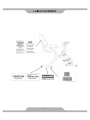
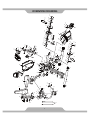
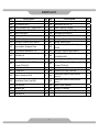
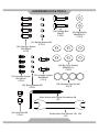
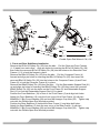
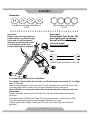
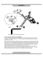
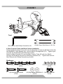
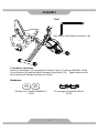
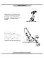
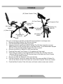
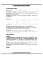
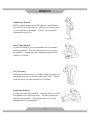
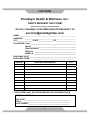
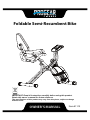
Foldable Semi-Recumbent Bike
IMPORTANT: Read all instructions carefully before using this product.
Retain this owner’s manual for future reference.
The specifications of this product may vary from this photo, subject to change
without notice.
OWNER’S MANUAL
Item #1113
TABLE OF CONTENTS
SERVICE ------------------------------------------------------------------------ 2
LABEL PLACEMENT --------------------------------------------------------- 3
PRODUCT SAFETY ---------------------------------------------------------- 4
OVERVIEW DRAWING ------------------------------------------------------ 5
PARTS LIST --------------------------------------------------------------------- 6
HARDWARE LIST & TOOLS ----------------------------------------------- 8
ASSEMBLY --------------------------------------------------------------------- 9
COMPUTER --------------------------------------------------------------------- 15
ADJUSTMENTS ---------------------------------------------------------------- 17
STORAGE ----------------------------------------------------------------------- 18
TROUBLESHOOTING & MAINTENANCE ------------------------------ 19
WARM UP ----------------------------------------------------------------------- 20
WARRANTY -------------------------------------------------------------------- 21
FAX FORM ---------------------------------------------------------------------- 22
1
SERVICE
IMPORTANT: FOR NORTH AMERICA ONLY
To request product service and order
replacement parts, please call our
customer service department at:
1-866-924-1688
Monday through Friday, 8:00 AM-5:00 PM Pacific Standard Time,
or email us at: [email protected]
Please visit our website at www.paradigmhw.com.
Please have the following information ready when requesting for service:
Your name
Phone number
Model number
Serial number
Part number
Proof of Purchase
Before returning this product to the store please contact
customer service at the contact number.
Paradigm Health & Wellness, Inc.
1189 Jellick Ave.
City of Industry, CA 91748, USA
2
LABEL PLACEMENT
3
PRODUCT SAFETY
Basic precautions should always be followed, including the following safety
instructions when using this equipment. Read all instructions before using
this equipment.
1.
2.
3.
4.
5.
6.
7.
8.
9.
10.
11.
12.
13.
14.
15.
16.
Read all the instructions in this manual and do warm up exercises before using
this equipment.
Before exercising and to avoid injuring your muscles, perform warm-up
exercise for each muscle group is highly recommended. Please refer to
Warm Up section of the Owner’s Manual.
Please make sure all components are not damaged and in working order
before use. This equipment should be placed on a flat surface while in use.
Using a mat or other material on the ground is recommended.
Please wear proper clothes and shoes when using this equipment; do not wear
clothes that might catch in any part of the equipment.
Do not attempt any maintenance or adjustments other than those described in
this manual. Should any problems arise, discontinue use and consult with
customer service at Paradigm.
Keep dry - do not operate in wet or moist condition.
Always hold on to the handlebar while using the recumbent bike.
To dismount, reduce pedaling speed gradually before you stop.
Do not use the equipment outdoors.
This equipment is for household use only.
Only one person should be on the equipment at any time.
Keep children and pets away from the product while in use.
This machine is designed for adults only.
This product requires a minimum of 6 feet of space for safe operation.
If you feel any chest pains, nausea, dizziness, or short of breath, you should
stop exercising immediately and consult your physician before continuing.
The maximum weight capacity for this product is 275 lbs/125 kgs.
WARNING: Before beginning any exercise program consult your
physician.
This is especially important for the persons who are over 35
years old or who have pre-existing health problems. Read all instructions
before using any fitness equipment.
CAUTION: Read all instructions carefully before operating this
product. Retain this Owner’s Manual for future reference.
4
84
29
62
80
81
85
91
82
5
83
87
77
62
69
79
28
82
76
93
62
89
34
75
11
91
78
74
81
60
27
69
3
93
90
6
59
90
29
28
5
7L
14
12
33
61
29
62
59
60 62
26 25
21
1
8 21
27
23L
11
92
17
88
24L
88
16
33
59
18L
15
66
85
20
63
49
9
13
48
2
15
31
59
46
28
29
21 62 60
68 47
19
39
65
38
29 62
4
47
86
22
68 51
24R
62 17
71
35
70
10
35 32
73
53
37
50
52
64
63
45
66
72
43
49
36
63
32
27
18R
67
44
58
42
27
57
55 44
56 54
45
40
20
23R
7R
44 45
25
41
26
45
42
44
43
30
63
OVERVIEW DRAWING
PARTS LIST
No.
Description
Qty No.
Description
Qty
001 Rear Frame
1
025 France Nut 3/8"
2
002 Front Frame
1
026 Crank Cover
2
003 Rear Stabilizer Ø50
1
027
004 Computer Frame
1
028 Big Curve Washer Ø8xØ25x1.5
6
005 Seat Post
1
029 Hexagon Cap Nut M8
7
006 Seat Cushion
1
030 Belt 230J3
1
007L Left Foot Pedal (9/16")
1
031 Belt 240J3
1
007R Right Foot Pedal (9/16")
1
032 Hexagon Socket Bolt M6x12
4
008 Axle Ø16
1
033
009 Computer
1
034 Nylon Nut M8
2
010 Computer Bracket
1
035 Spring Washer Ø6
4
011
2
036 Magnet Bracket
1
012 Seat Post Plastic Bushing
1
037 Magnet 65x20x8
2
013 Tension Control Knob (960L)
1
038 Safety Pin Ø10x110
1
1
039 Sensor Bracket
1
015 Sensor with Wire (900L)
1
040 Flywheel Ø200
1
016 Wire Grommet
1
041 Belt Wheel with Crank Axle Ø155
1
017 Hexagon Socket Bolt M8x100
2
042 Bearing Bracket Ø74x13
2
018L Left Shroud
1
043 Bearing Cup Ø70xδ2
2
018R Right Shroud
1
044 Bearing 6003
4
019 Front Stabilizer Ø50
1
045 C-ring Ø17
6
2
046 Belt Wheel Ø150
1
021 Round Plastic Bushing
6
047 Bearing 6000
2
022 Safety Pin Ø8x110
1
048 Axle Ø12.7x94.5
1
023L Left Crank
1
049 Eyebolt M6
2
023R Right Crank
1
050 Tension Bracket
2
024L Front Left Wheel Cap
1
051 Spring Clip Ø10
1
024R Front Right Wheel Cap
1
052 Nylon Nut M6
2
014
020
Rear Stabilizer End Cap
Seat Height Adjustment Knob
M16
Round Phillips Head Drilling
Screw ST4.2x18
6
Round Phillips Head Tapping
Screw ST4.2x20
Extension Hand Pulse Sensor
Wire I
8
1
PARTS LIST
No.
Description
Qty No.
Description
Qty
053 Nut M10x1.5xδ6.5
1
074 Back Cushion
1
054 Big Washer Ø10
1
075 Handlebar Ø25x1.5t
1
055 Wave Washer Ø17.5xØ23xδ0.3
1
076 Back Cushion Frame
1
056 Idle Wheel Axle Ø17x37
1
077 Square End Cap (30x30)
1
057 Nylon Nut M10
1
078 Carriage Bolt M8x50
2
058 Bearing 6202
1
079 Hexagon Socket Bolt M8x40
2
059 Oval End Cap
6
080 Hexagon Socket Bolt M8x45
4
060 Hexagon Socket Bolt M8x15
6
081 Spring Washer Ø8
8
061 Retractable Support Rod
1
082
Back Cushion Tube End Cap
15x30
4
062 Big Washer Ø8xØ25x1.5
9
083 Hexagon Socket Bolt M8x75
1
063 Bolt M6x10
8
084
Handlebar Foam Grip
Ø23xØ32x350
2
064 Washer Ø6.5xØ13xδ0.5
1
085 Plastic Washer Ø8
1
086
066 Nut M10x1.5xδ8
2
087 Back Cushion Tube
1
067 C-ring Ø15
1
088 Square End Cap (38x38)
2
068 Plastic Washer Ø10
2
089
Extension Hand Pulse Sensor
Wire III
2
069 Handlebar End Cap Ø25
2
090
Extension Hand Pulse Sensor
Wire II
2
070 Bolt M5x20
1
091 Hand Pulse Sensor
2
071 Washer Ø5
1
092 Safety Pin Ø8x65
1
072 Spring Ø8xØ0.8x60
1
093 Wire Grommet Ø12
2
073 Bolt M5x10
2
065
Round Phillips Head Drilling
Screw ST4.2x12
7
Round Phillips Head Tapping
Screw ST4.8x15
4
2
HARDWARE LIST & TOOLS
(78) Carriage Bolt
M8x50
2 PCS
(62) Big Washer
Ø8xØ25x1.5
2 PCS
(81) Spring Washer Ø8
4 PCS
(80) Hexagon Socket
Bolt M8x45
4 PCS
(28) Big Curve Washer
Ø8xØ25x1.5
6 PCS
(32) Hexagon Socket
Bolt M6x12
4 PCS
(79) Hexagon Socket
Bolt M8x40
2 PCS
(29) Hexagon Cap Nut M8
4 PCS
(35) Spring Washer Ø6
4 PCS
Allen Wrench with Phillips Screwdriver 5#
1 PC
(34) Nylon Nut M8
2 PCS
Double Open End Wrench 13#, 15#
1 PC
8
ASSEMBLY
2
4
2
22
38
61
29
28
1
29
28
92
1
3
29
Tool:
19
28
Double Open End Wrench 13#, 15#
1. Front and Rear Stabilizers Installation
Remove the Ø10x110 Safety Pin (38) from the bike. Pull the Rear and Front Frames
(1, 2) apart from each other. Align pin holes for inserting the Ø10x110 Safety Pin (38)
then insert the removed Ø10x110 Safety Pin (38) into the holes on the Rear and Front
Frames (1, 2) to lock the frames in place.
Remove the Ø8x110 Safety Pin (22) from the bike. Pull the Computer Frame (4)
forward and align pin holes for inserting the Ø8x110 Safety Pin (22) then insert the
removed Ø8x110 Safety Pin (22) into the holes on the Computer Frame (4) and Front
Frame (2) to lock the Computer Frame (4) in place.
Remove the Ø8x65 Safety Pin (92) from the bike. Pull the Retractable Support Rod (61)
up and align pin holes for inserting the Ø8x65 Safety Pin (92) then insert the removed
Ø8x65 Safety Pin (92) into the holes on the Front Frame (2) and Retractable Support
Rod (61) to lock the Retractable Support Rod (61) in place.
Position the Front Stabilizer (19) in front of the Front Frame (2) and align bolt holes.
Attach the Front Stabilizer (19) onto the front curve of the Front Frame (2) with two
Ø8xØ25x1.5 Big Curve Washers (28) and two M8 Hexagon Cap Nuts (29). Tighten cap
nuts with the Double Open End Wrench provided.
Position the Rear Stabilizer (3) behind the Rear Frame (1) and align bolt holes.
Attach the Rear Stabilizer (3) onto the rear curve of the Rear Frame (1) with two
Ø8xØ25x1.5 Big Curve Washers (28) and two M8 Hexagon Cap Nuts (29). Tighten cap
nuts with the Double Open End Wrench provided.
9
ASSEMBLY
Hardware:
(28) Big Curve Washer Ø8xØ25x1.5
4 PCS
(29) Hexagon Nut Cap M8
4 PCS
․․․․․․․․․․․․․․․․․․․․․․․․․․․․․․․․․․․․․․
Important:
Screw Right Foot Pedal (7R)
into right crank clockwise!
Screw Left Foot Pedal (7L)
into Left crank
counter-clockwise!
Important:
Please make sure the right foot
pedal matches up with the right
crank and the left foot pedal
matches up with the left crank.
If reversed the cranks may
become damaged or stripped.
7L
Tool:
23L
2
Double Open End Wrench 13#, 15#
23R
7R
2. Left and Right Foot Pedals Installation
The Cranks, Pedal Shafts, Foot Pedals, and Pedal Straps are marked “R” for Right
and “L” for Left.
Insert the pedal shaft of Left Foot Pedal (7L) into threaded hole in the Left Crank (23L).
Turn the pedal shaft by hand in the counter-clockwise direction until snug.
Note: DO NOT turn the pedal shaft in the clockwise direction, doing so will strip
the threads.
Tighten the pedal shaft of Left Foot Pedal (7L) with the Double Open End Wrench
provided.
Insert pedal shaft of Right Foot Pedal (7R) into threaded hole in Right Crank (23R).
Turn the pedal shaft by hand in the clockwise direction until snug.
Tighten pedal shaft of Right Foot Pedal (7R) with the Double Open End Wrench
provided.
10
ASSEMBLY
6
33
5
6
14
90
12
2
81
60
5
Tool:
Allen Wrench with Phillips Screwdriver 5#
3. Seat Cushion and Seat Post Installation
Remove four M8x15 Hexagon Socket Bolts (60) and four Ø8 Spring Washers (81) from
underside of the Seat Cushion (6). Remove bolts with the Allen Wrench with Phillips
Screwdriver provided.
Align bolt holes on underside of Seat Cushion (6) with holes on top of Seat Post (5), then
attach with four M8x15 Hexagon Socket Bolts (60) and four Ø8 Spring Washers (81) that
were removed. Tighten bolts with the Allen Wrench with Phillips Screwdriver provided.
Connect the Extension Hand Pulse Sensor Wire I (33) from the Front Frame (2) to the
Extension Hand Pulse Sensor Wire II (90) from the Seat Post (5).
Insert the Seat Post (5) into the seat post bushing on the tube of the Front Frame (2).
Adjust seat position and insert the M16 Seat Height Adjustment Knob (14). Turn the
M16 Seat Height Adjustment Knob (14) in a clockwise direction to tighten.
11
ASSEMBLY
5
74
80
81
34
5
62
87
78
76
Tool:
Allen Wrench with Phillips Screwdriver 5#
Double Open End Wrench 13#, 15#
4. Back Cushion Frame and Back Cushion Installation
Attach the Back Cushion Frame (76) onto the Seat Post (5) with two M8 Nylon Nuts (34),
two Ø8xØ25x1.5 Big Washers (62), and two M8x50 Carriage Bolts (78). Tighten nylon
nuts with the Double Open End Wrench provided.
Attach the Back Cushion (74) onto the Back Cushion Tube (87) with four M8x45
Hexagon Socket Bolts (80) and four Ø8 Spring Washers (81). Tighten bolts with the
Allen Wrench with Phillips Screwdriver provided.
Hardware:
(80) Hexagon Socket Bolt M8x45
4 PCS
(78) Carriage Bolt M8x50
2 PCS
(81) Spring Washer Ø8
4 PCS
(62) Big Washer Ø8xØ25x1.5 (34) Nylon Nut M8
2 PCS
2 PCS
12
ASSEMBLY
Tool:
Allen Wrench with Phillips Screwdriver 5#
76
75
28
79
5. Handlebar Installation
Attach the Handlebar (75) onto the Back Cushion Frame (76) with two Ø8xØ25x1.5 Big
Curve Washers (28) and two M8x40 Hexagon Socket Bolts (79). Tighten bolts with the
Allen Wrench with Phillips Screwdriver provided.
Hardware:
(28) Big Curve Washer Ø8xØ25x1.5
2 PCS
(79) Hexagon Socket Bolt M8x40
2 PCS
13
ASSEMBLY
9
Tool:
10
15
33
32
35
4
35
32
Allen Wrench with Phillips Screwdriver 5#
90 5
75
89
6. Computer Installation
Connect the Extension Hand Pulse Sensor Wires III (89) from the Handlebar (75) to the
Extension Hand Pulse Sensor Wires II (90) from the Seat Post (5).
Install the Computer Bracket (10) to the Computer Post (4) by sliding the Computer
Bracket (10) into the Computer Frame (4), using four M6x12 Hexagon Socket Bolts (32)
and four Ø6 Spring Washers (35). Tighten bolts with the Allen Wrench with Phillips
Screwdriver provided.
Plug the Sensor Wire (15) from the Computer Frame (4) into the SENSOR receptacle on
the back of the Computer (9).
Plug the Extension Hand Pulse Sensor Wire I (33) from the Computer Frame (4) into the
PULSE receptacle on the back of the Computer (9).
Hardware:
(32) Hexagon Socket Bolt M6x12
4 PCS
(35) Spring Washer Ø6
4 PCS
14
COMPUTER
SPECIFICATIONS:
TIME ---------------------------------------------- 0:00-99:59 MIN: SEC
SPEED ------------------------------------------- 0.0-999.9 MPH
DIST (DISTANCE) ----------------------------- 0.00-99.99 MILE
CAL (CALORIES) ------------------------------ 0.0-999.9 KCAL
ODO (ODOMETER) -------------------------- 0.00-99.99 MILE
PULSE ------------------------------------------- 40-200 BEATS/MIN
USING YOUR COMPUTER
The computer can be activated by pressing the button or by pedaling.
equipment idle for 4 minutes, the power will turn off automatically.
If you leave the
BUTTON FUNCTIONS:
Press the button to select the function of the computer.
Press and hold the button for 3 seconds to reset all data values to zero except the
ODO (ODOMETER) data values.
COMPUTER FUNCTIONS:
SCAN: Automatically scans each function in sequence with change every 6 seconds.
NOTE: If you do not want to use the SCAN function, press the button to select one of the
other functions.
TIME: Displays your elapsed workout time in minutes and seconds.
SPEED: Displays the current training speed.
DIST (DISTANCE): Displays the cumulative distance traveled during workout.
CAL (CALORIES): Displays approximate amount of calories burned during workout.
(This data is a rough guide for comparison of different exercise sessions and should not
be used in medical treatment).
ODO (ODOMETER): Displays the total accumulative distance traveled. The
ODOMETER data values can not be clear to zero by pressing and holding the button for
3 seconds. If you take out the batteries from the computer, the ODOMETER data
values will clear to zero.
PULSE: Displays your current heart-rate readings after you grip the handlebar pulse
sensors with both your hands during exercise. To ensure the pulse readout is more
precise, always hold on to the handlebar pulse sensors with both hands instead of one
hand when you are trying to monitor your heart-rate reading.
15
COMPUTER
HOW TO INSTALL THE BATTERIES:
1. Remove the battery cover on the back of the computer.
2. Place two "SIZE-AAA" batteries into the battery housing.
3. Insure batteries are correctly positioned and battery springs are proper contact with
batteries.
4. Re-install the battery cover.
5. If the display is illegible or only partial segment appears, remove the batteries and
wait 15 seconds before reinstalling.
16
ADJUSTMENTS
Adjusting the Tension Control Knob
To increase the tension, turn the tension
control knob in a clockwise direction.
To decrease the tension, turn the tension
control knob in a counterclockwise
direction.
Tension Control Knob
Adjusting the Seat Height
Turn the seat height adjustment knob in a
counterclockwise direction until the seat
post can be slid up or down and then slide
the seat post up or down direction to the
suitable position. Lock the seat post in
place by tightening the seat height
adjustment knob in a clockwise direction.
Seat Height Adjustment Knob
17
STORAGE
(87) Back Cushion Tube
(2) Front Frame
(22) Safety Pin
Ø8x110
(92) Safety Pin
Ø8x65
(38) Safety Pin
Ø10x110
(1) Rear Frame
(4) Computer Post
(22) Safety Pin
Ø8x110
(92) Safety Pin
Ø8x65
(38) Safety Pin
Ø10x110
For your convenience, the bike can be folded up and placed in a storage area.
1. Remove the Ø8x65 Safety Pin (92) from the bike.
2. Pull the Retractable Support Rod (61) down.
3. Align pin holes for inserting the Ø8x65 Safety Pin (92) then insert the removed
Ø8x65 Safety Pin (92) into the holes on the Rear Frame (1) and Retractable Support
Rod (61) to lock the Retractable Support Rod (61) in place.
4. Remove the Ø10x110 Safety Pin (38) from the bike.
5. Push the Rear and Front Frames (1, 2) together until they meet.
6. Align safety pin holes for inserting the Ø10x110 Safety Pin (38) then insert the
removed Ø10x110 Safety Pin (38) into the holes on the Rear and Front Frames
(1, 2) to lock the frames in place.
7. Remove the Ø8x110 Safety Pin (22) from the bike.
8. Pull the Computer Frame (4) forward then insert the removed Ø8x110 Safety Pin
(22) into the holes on the Front Frame (2) to lock the Computer Frame (4) in place.
9. Push the Back Cushion Tube (87) down until back cushion meets seat cushion.
18
TROUBLESHOOTING & MAINTENANCE
TROUBLESHOOTING
PROBLEM: There is no display on the computer console.
SOLUTION: Verify the sensor wire that comes from the computer post is properly
plugged into the SENSOR receptacle located on the back of the computer.
SOLUTION: Check if the batteries are correctly positioned and battery springs are
in proper contact with batteries.
SOLUTION: The batteries in the computer console may be dead. Replace with
new batteries.
PROBLEM: There is no heart-rate reading or there is erratic / inconsistent reading.
SOLUTION: Verify the extension hand pulse sensor wire I that comes from the
computer frame is properly plugged into the PULSE receptacle located on the back
of the computer.
Verify the extension hand pulse sensor wires III from the handlebar is properly
connected to the hand pulse sensor wires II from the seat post.
SOLUTION: To ensure the pulse readout is more precise, always hold on to the
handlebar grip sensors with both hands instead of just with one hand.
SOLUTION: Avoid gripping the hand pulse sensors too tight. Try to maintain
moderate pressure while holding onto the hand pulse sensors.
PROBLEM: The recumbent bike makes a squeaking noise when in use.
SOLUTION: The bolts may be loose on the training bike. Please inspect all of the
bolts and tighten any loose bolts.
MAINTENANCE
Cleaning
The recumbent bike can be cleaned with a soft cloth and mild detergent. Do not
use abrasives or solvents on plastic parts. Please wipe your perspiration off the
recumbent bike after each use. Be careful not to get excessive moisture on the
computer display panel as this might cause an electrical hazard or electronics to
fail.
Please keep the recumbent bike, especially, the computer console, out of direct
sunlight to prevent screen damage or premature wear.
Please inspect all assembly bolts and pedals on the machine for proper tightness
every week.
Storage
Store the recumbent bike in a clean and dry environment away from children.
19
WARM UP
Quadriceps Stretch
With one hand against a wall for balance, reach behind
you and pull your right foot up. Bring your heel as close
to your buttocks as possible. Hold for 15 counts and
repeat with left foot up.
Inner Thigh Stretch
Sit with the soles of your feet together with your knees
pointing outward. Pull your feet as close to your groin
as possible. Gently push your knees towards the floor.
Hold for 15 counts.
Toe Touching
Slowly bend forward from your waist, letting you back and
shoulders relax as you stretch toward your toes. Reach
down as far as you can and hold for 15 counts.
Hamstring Stretch
Sit with your right leg extended. Rest the sole of your left
foot against your right inner thigh. Stretch toward your
toe as far as possible. Relax and hold for 15 counts.
Repeat with left leg extended.
20
WARRANTY
Paradigm Health & Wellness, Inc. warrants to the original purchaser that this
product is free from defects in material and workmanship when used for the
purpose intended, under the conditions that it has been installed and operated in
according to Paradigm Health & Wellness, Inc.’s Owner’s Manual. Paradigm
Health & Wellness, Inc.’s obligation under this warranty is limited to replacing free
of charge, any parts which may prove to be defective under normal home use.
This warranty does not include any damage caused by improper operation,
misuse or commercial application. From the date of purchase, the product is
warranted to be free from defects for 1 (one) year. All parts and workmanship,
including computer display, upholstery, foam, ball bearings, pulleys, belts, cables,
wires, shocks, covers, tension, internal mechanism, wheels, pedals, knobs,
accessories and hardware are to be free from defects for 90 days. This warranty
is offered only to the original owner and is not transferable. Proof of purchase is
required. This warranty is offered only to the original owner and is not
transferable.
Ordering Replacement Parts
Replacement parts can be ordered by calling or emailing our customer service
department
[email protected]
1-866-924-1688
Monday through Friday, 8:00 AM - 5:00 PM (PST).
When ordering replacement parts please have the following information ready:
1. Owner’s Manual
2. Model Number
3. Description of Parts
4. Part Number
5. Date of Purchase
21
FAX FORM
Paradigm Health & Wellness, Inc.
PARTS REQUEST FAX FORM
Please fax this form to (1-626-810-2166)
OR YOU CAN EMAIL CUSTOMER SERVICE REQUESTS TO
[email protected]
NAME: _______________________________________________________
ADDRESS: ____________________________________________________
CITY ______________ STATE ______________ ZIP ___________________
TELEPHONE: (Day) _____________________________________________
(Night) ____________________________________________
(Email Address) ____________________________________
SERIAL#: __________________________________________
MODEL#: __________________________________________
PURCHASE DATE: ______________________________________________
PURCHASE FROM: ______________________________________________
PART #
DESCRIPTION/REASON
QTY
“YOUR ORDER WILL BE PROCESSED WITHIN 3 BUSINESS DAYS”
OFFICIAL USE ONLY
SHIP DATE: ___________________________________________
TRK #: _______________________________________________
BACK ORDER: ________________________________________
22