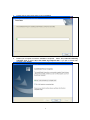
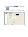
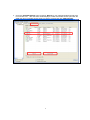
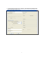
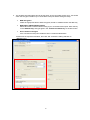
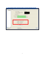
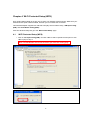
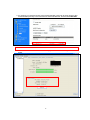
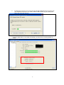
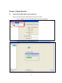
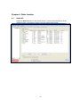
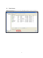
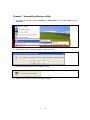
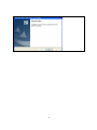
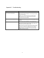
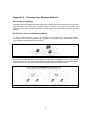
1
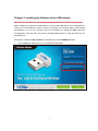
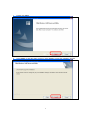
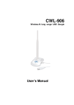
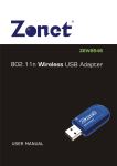
CQU-906 Wireless-N Pico USB Dongle User Manual Ver 1.00 Table of Contents Chapter 1. 1.1. 1.2. 1.3. Introduction ............................................................................................. 3 About CQU‐906 ...................................................................................................... 3 Main Features ........................................................................................................ 3 Getting to Know CQU‐906 ...................................................................................... 3 Chapter 2. Installing the Software of the USB adapter ............................................... 4 Chapter 3. Configuring Your Wireless Network .......................................................... 7 Chapter 4. Wi‐Fi Protected Setup (WPS) ...................................................................13 4.1. 4.2. Wi‐Fi Protected Setup (WPS) ............................................................................... 13 Wi‐Fi Protected Setup (WPS) ............................................................................... 16 Chapter 5. 5.1. 5.2. Access Point and Station mode selection ............................................................ 18 Access Point Mode ............................................................................................... 19 Chapter 6. 6.1. 6.2. Mode Selection .......................................................................................18 Other function.........................................................................................20 Radio Off............................................................................................................... 20 Disable Adapter .................................................................................................... 21 Chapter 7. Uninstalling Wireless Utility ....................................................................22 Appendix 1. Troubleshooting ......................................................................................24 Appendix 2. Planning Your Wireless Network .............................................................25 2 Chapter 1. Introduction 1.1. About CQU-906 Thank you for choosing CQU-906 Wireless-N Pico USB Dongle. CQU-906 is a new generation super mini, low power consumption wireless USB dongle. It provides high security level and reasonable performance based on IEEE 802.11b/g/n standard. CQU-906 can be used on PC/Notebook’s USB port to connect to wireless AP. With an integrated wireless processing chipset, CQU-906 provides a maximum link speed of 150Mbps. Moreover, CQU-906 also provides a physical WPS button. When connecting to a WPS support access point, you can just press the button and supplely set up the security. It combines Station (LAN Adapter) and Access Point in one, allowing the host PC/ Notebook to easily connect other Wi-Fi devices around, such as laptops, PDAs, and Wi-Fi phones to the internet without complication of wires. 1.2. Main Features The following lists the main features of the Wireless-N High Power USB adapter. 1.3. Super mini size and low power consumption design. Complies with IEEE 802.11n and backward compatible with IEEE 802.11b/g Data transition of up to 150Mbps data rate WMM (802.11e) function improves the quality of VoIP and video service 2 Application Modes: Station (LAN Adapter) and Access Point. Easy Mode changing by running Utility High security level, supports major encryption methods like WEP, WPA, and WPA2 encryption Supports one touch encryption method (WPS) to simplify the secure establishment of a wireless network Getting to Know CQU-906 This section describes the WPS button and LED indicator of the Wireless-N USB adapter. LED State Description On (Stable) Wireless USB dongle is powered on. Off Wireless USB dongle is powered off. LINK / ACT Blinking Fast WPS mode enabled. Blinking Slow Data is transmitting or receiving. 3 Chapter 2. Installing the Software of the USB adapter Notes: Driver installation process of Windows 2000/2003/Vista/7 is similar to Windows XP Before installing your Wireless-N USB adapter, insert the Auto-Install CD into your CD-ROM drive. Unless you have disabled the auto-run feature of Windows, the AutoPlay Menu should appear automatically. If not, you can manually access the installation by clicking the Start button and choosing Run. In the drop-down box type D:\ AUTORUN.EXE (where D: is the drive letter for your CD-ROM drive). Alternatively, double-click My Computer and double-click on the CD-ROM drive icon. 1. Click on Driver to install driver for your Wireless-N USB adapter. 4 2. Please click “Next”. 3. Click “Install” to start the setup program or click “Cancel” to abort the installation process. 5 4. Please wait for few minutes when running installation 5. Restart your computer to make the installation completed. Select “Yes, I want to restart my computer now” or select “No, I will restart my computer later” if you plan to restart later. And then, click “Finish” 6 Chapter 3. Configuring Your Wireless Network 1. Double click on the green wireless signal icon icon in your taskbar or the shortcut on the desktop. 2. Configuration utility will scan for all wireless access points automatically. You can use the utility to check the linking information or go to the “Available Network” page to search for available wireless network 7 3. Go to the “Available Network” page, and click “Refresh” if your preferred wireless access point is not shown here. After the Scan results displayed, select the wireless access point with the SSID (the name of wireless access point) you want to connect and click “Add to Profile” 8 4. The wireless Network Properties window will pop up. If the access point you selected enables encryption (WEP, WPA, WPA2, and etc…), please setup the wireless securities settings. If not, simply click the “OK” to and skip to step 6 9 5. The wireless securities setting should be the same as the connected access point. You should check the encryption details of your connected access point before setting this setup. WEP Encryption Select the appropriate level of WEP encryption, 64-Bit or 128-Bit and enter the WEP key WPA-PSK or WPA2-PSK Encryption Select WPA-PSK or WPA2-PSK according to your connected access point. Enter the key in the “Network Key” and type again in the “Confirmed network key” to double confirm. 802.1x wireless configure If the connected access point enable the 802.1x wireless authentication Please fill in the required information, then click “OK” to finish the setting and back to “General” page 10 6. Once the wireless network connected successfully, you will see IP information in the page. 11 7. Go to “Profile” page to ensure the selected wireless access point has been added. In this page, you can also remove, edit, duplicate and set default. 12 Chapter 4. Wi-Fi Protected Setup (WPS) Wi-Fi Protect Setup (WPS) is an easy way to setup your wireless network security. Make sure your selected access point is WPS-enabled, and then you can activate the connection. This Wireless adapter supports two methods to simplify secure network setup, “PIN Input Config (PIN)” and “Push Button Config (PBC)”. Click into Wireless Utility and go to the “WiFi Protect Setup” page. 4.1. Wi-Fi Protected Setup (WPS) 1. Click on “Pin Input Config (PIN)” and click “Yes” to select a specific access point or click “No” to jump to step 3. Note: The PIN Number will renew each time you leave this setting page. 13 2. Click “Refresh” button to re-search WPS enabled access points nearby. Choose an access point you want to connect, the click “Select” 3. It will take few seconds to one minute for the USB Adapter establishes the connection with your selected Access Point. During this period, your need to open the Access Point’s setup page and input the PIN code 14 4. For example, our selected access point named CQR-980. Click into its setup pages to WiFi Protected Setup and key in the PIN code into Client PIN Number, and then click Start PIN. Note: You need to make this PIN function started before the WPS connection times out from client side . 5. Once the WPS status is connected successfully, you will see the connecting details as below. 15 4.2. Wi-Fi Protected Setup (WPS) 1. Click “Push Button (PBC)” button Note: You can push the physical ‘WPS’ button on USB adapter or the virtual “PBC” button in Wireless Utility. 16 2. It will take few seconds to one minute for the CQU-906 establishes the connection with your selected access point. Your need to start the PBC function in your access point before the connection time out 3. Once the WPS status is connected successfully, you will see the connecting details as below. 17 Chapter 5. Mode Selection 5.1. Access Point and Station mode selection Users can switch between Station and Access Point modes. 1. Click on “Mode” and select “Access Point” change to Access Mode. 2. Please wait changing to “Access Point” mode. 18 5.2. Access Point Mode Soft AP function is to enable your wireless adapter as a Virtual Wi-Fi Access Point to extend Wireless coverage and share internet connection with others. When you change to Access Point mode, Wireless Utility will enable “Internet Connection Sharing” function automatically. Please fill in the related information. Item Network Name (SSID) Channel Network Authentication Data Encryption Network Key Description Give a SSID to shared network. Select a channel for shared network Select authentication type for shared network Select encryption type Setup the wireless security key for shared network 19 Chapter 6. Other function 6.1. Radio Off Enable the Radio Off will turn off the radio function. It means CQU-906 will turn off the wireless function. The wireless network connection will be disconnected. 20 6.2. Disable Adapter Disable the CQU-906 adapter will turn off the USB adapter function. It means all functions of CQU-906 will be turn off. 21 Chapter 7. Uninstalling Wireless Utility 1. Go to start menu and then select “Programs” or “All Programs”. Find a folder “CNet” and click “Uninstall”. 2. Windows will pop the message as below, please click “Yes” 3. It will take few seconds to run uninstall process. 4. Please click “Finish” to exit the uninstall program 22 23 Appendix 1. Troubleshooting PROBLEM CORRECTIVE ACTION None of the LEDs turn on when I plug in the wireless USB adapter. Make sure you have turned on your computer Make sure you have installed the correct utility and driver for your WLAN card. Restart your computer and plug in the adapter again. Make sure there is no hardware conflict. Check your computer resource information. I cannot access the configuration utility Make sure the WLAN adapter is installed / plugged in properly. Make sure you have installed the correct utility version. I cannot connect to a wireless network Make sure the ACT LED on the WLAN adapter is blinking. Make sure the wireless router is within range. Move your computer closer to the wireless router. Make sure that you have set the wireless network settings correctly. For example, the SSID and security settings. Make sure there is no radio interference (for example, cordless phones, microwave oven, etc) that may affect wireless transmission quality. 24 Appendix 2. Planning Your Wireless Network A2-1 Network Topology A wireless local area network (WLAN) is exactly like a regular local area network (LAN), except that each computer in the WLAN uses a wireless device to connect to the network. Computers in a WLAN share the same frequency channel and SSID, which is an identification name for wireless devices. A2-2 Ad-hoc versus Infrastructure Mode An ad-hoc wireless LAN is a group of computers, each equipped with one WLAN adapter, connected as an independent wireless LAN. Computers in a specific ad-hoc wireless LAN must all be configured to share the same radio channel. Figure 2-1 Ad-hoc Mode An integrated wireless and wired LAN is called an Infrastructure configuration. In this mode, a group of wireless nodes and an Access Point compose a Basic Service Set (BSS). Each wireless node in a BSS can talk to any computer in the wired LAN infrastructure via the Access Point. Figure 2-2 Infrastructure Mode 25