1
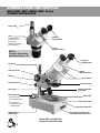
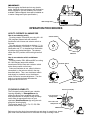
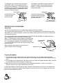
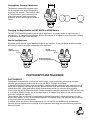
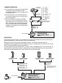
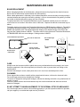
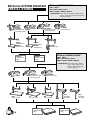
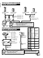
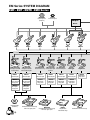
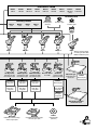
EMF EMT EMTR EMX Series STEREO MICROSCOPES INSTRUCTION MANUAL CONTENTS NOMENCLATURE AND FUNCTION 2-3 THE USE AND CARE 4 Unpacking 4 How to Rotate the Head 4 OPERATION PROCEDURES 5-7 How To Operate Illuminators 5 Focusing Capability 5 Precise Focus On Specimen 6 Focusing Procedure 6 Interpupillary Distance Adjustment 7 Changing The Magnification On EMT, EMTR And EMX Models 7 How To Use Eyeshield 7 PHOTOGRAPHY AND TELEVISION 7-8 Photography 7 Camera Operation 8 Television 8 MAINTENANCE AND CARE 9 Bulb Replacement 9 Care 9 Cleaning 9 EM Series SYSTEM DIAGRAM 10-13 EMF EMT EMTR EMX Series INSTRUCTION MANUAL 1 NOMENCLATURE AND FUNCTION MEIJI EMF EMT EMTR EMX Series STEREO MICROSCOPE Photo Tube Lever for switching the image from one of the binocular eyepieces vertically up to the film plane Eyepieces with Eyeshield Diopter Adjustment Ring EMTR-2 Trinocular Stereo Body Eyetube Inclination : 45 。 Eyepieces with Eyeshield Set Screw Focusing Knob Diopter Adjustment Ring Clamp Prism House Collar Set Screw Turret Objective Pilar Collar Incident Illuminator Lamp Cover Selector Switch (I) Incident Light Stage Clips (T) Transmitted Light Glass Stage Plate (IT) Incident and Transmitted Lights simultaneously Stage Plate Set Screw Dimmer Switch (PBH Stand) Base with Transformer and Transmitted Illuminator built in Model EMT-1 with SWF10X mounted on PBH (PB) Stand 2 Model EMX-1 with SWF10X mounted on PX Stand Eyeshield Diopter Adjustment Ring Eyepieces with Eyeshield Set screw Prism House Focusing Knob Fixed objective Clamp Stage Clips Collar Set Screw Stage Plate Set Screw Base Reversible Stage Plate Black / White Model EMF-1 with SWF10X mounted on P Stand 3 THE USE AND CARE OF MEIJI EM Series "MEIJI" EMF, EMT, EMTR AND EMX SERIES WIDEFIELD STEREO MICROSCOPE The MEIJI EM Series (EMF,EMT, EMTR and EMX Series) Widefield Stereo Microscope consists of two converging compound microscopes which are combined as a unit to focus simultaneously on the same field of object. Each body tube is fitted with a set of Porro prisms to erect the image and matched achromatic objectives and super widefield eyepieces to furnish a very wide flat field of view. Each eye observes the object from a different perspective, consequently, deep stereoscopic relief is produced in the fused image. This MEIJI EM Series Stereo Microscope widely is used for various applications such as assembly and inspection of semiconductor devices, and as an indispensable part in bonding machines and microtomes, as well as for educational, clinical and research purposes. This series stereo microscope is used as follows: UNPACKING This EM series stereo microscope is usually supplied in a styrofoam containers. Remove the instrument from its container by grasping the stereo microscope body and supporting the base with the other hand. Place the instrument on a firm flat table. (No packing material should be discarded until the instrument has been checked, since some may contain accessory equipment which can not be attached to the instrument.) When supplied in a wooden cabinet, remove the instrument from the cabinet by unscrewing the two large screws which are used to fasten the instrument to the cabinet through the bottom of the cabinet, with a coin or large screwdriver. If you ordered zoom stereo body and stand separately, loosen the set screw and insert the body into the holder then tighten the set screw after setting at the desired position. Insert the eyepieces into eyetube Set screw Stereo body can rotate 360 degree on the holder Holder How to Rotate the Head: 4 A special feature of this series stereo microscope is the rotation of the stereo microscope body through 360° so that it can be utilized either in the conventional position or with the stage nearest to the observer. To rotate the stereo microscope body, loosen the set screw. IMPORTANT! Before plugging the illuminator into any electric outlet, make sure that transfomers and illumination bases supplied to you are suitable to the current available. (When shipped, these will be labelled as to mains voltage and cycles specification.) Main voltage label MAINS AC100V-120V OPERATION PROCEDURES HOW TO OPERATE ILLUMINATORS OFF T IT OFF PB Stand OFF I T OFF Selector Switch IT How to use selector switch and dimmer switch Focusing stands, PBH, ABH and ABE, are using 6V 10W Halogen lamps with suitable transformers built-in base and a selector switch and a dimmer switch on the base. Selector Switch I How to use selector switch Focusing stands, PB and AB, are using 6V 1.2A (7W) tungsten filament bulb with suitable transformer built-in base and selector switch on the base. Turn the selector switch knob to indicate [ I ] for oblique illumination, to indicate [T] for transmitted illumination and [IT] for simultaneous illumination by oblique and transmitted lights. The selector switch has OFF position at the both right and left ends. Select an illuminator to use, either incident or transmitted, by the selector switch in the way described above. Then, turn the dimmer switch knob slowly to clockwise to turn the dimmer switch ON and to increase brightness. Turn the knob to counterclockwise to decrease the brightness and to turn OFF. Dimmer Switch FOCUSING CAPABILITY The Pole-type focusing stands have a double focusing capability, i.e. Rough Focus (by sliding the whole focus assembly and stereo body up and down on the pillar, fixing the clamp screw when in approximate focus on your specimen), Precise Focus (by using the rack and pinion focusing knob). The focusing stands, P, PL, PX, PC, PB, PBH and BX are the Pole-type. PBH Stand Focusing assembly Focusing Knob Clamp Screw Pillar collar and clamp Screw PBH Stand Before moving the whole focus assembly up and down for rough focus, loosen pillar collar once and make sure to reset after the rough focusing is done. 5 The Rigid arm type focusing stands (except the model ABE) have a focusing capability only by rack and pinion adjustment. This means that the available range of specimen sizes/depths which can be accommodated is somewhat less than in the case of Pole-type stands. The Rigid arm type ABE focusing stand is with integral focus block and extendable working distance. Provides transmitted and incident halogen illumination. Clamp Screw Focusing Knob A, AB and ABH stands are rigid arm type focusing stands. To extend working distance, loosen the clamp screw and extend the arm upward and set the screw back. ABE Extendable Stand AB Stand PRECISE FOCUS ON SPECIMEN Stage Plates You should now decide which of the stage plates supplied will be most suitable. The focusing stands with plain bases, P, PL, PX, PC and A, are supplied with reversible black and white stage plates. Your selection depends on which side, black or white, gives the best contrast conditions with your selected specimen. The focusing stands with transmitted illuminators, PB, PBH, AB, ABH and ABE, are supplied with clear glass stage plates and reversible black and white stage plates. If the specimen is semi-transparent, the glass stage plate shoud be used with transmitted illumination switched Black and White on. If the specimen is opaque, use the black/white stage. Stage Plate Your selection depends on which side, black and white, gives the best contrast. When replacing stage plate loosen the set screw which is visible in front of the stage. Stage plate set screw AB Stand Focusing Procedure (1) Look through the right eyepiece and, using only the right eye, focus on a plain surfaced objective centered on the stage. Adjust the focusing knob until the image is sharp without disturbing the focusing knob. (2) Look through the left eyepiece and, using only the left eye, adjust the Eyepiece Adjusting Ring, clockwise or counterclockwise, until the image is in sharp focus. (3) Each observer must focus the microscope to his individual requirements. However, a change of specimen requires only a slight readjustment of the focus. An alternate scheme for focusing may be used. Instead of closing either eye, the left or right side can be blocked off by holding a bit of opaque material below one side or the other of the eyepiece, and the same basic procedure followed as above. 6 54-74mm Interpupillary Distance Adjustment: The distance between the eyepiece tubes can be adjusted to the proper interpupillary distance of the observer. Take the both sides of Prism Houses in your hands and move inward and outward, looking through the eyepieces, until the both fields are viewed as Fused. "Fused" Changing the Magnification on EMT, EMTR and EMX Models The EMT, EMTR and EMX models have the paired objectives in a rotatable mount for rapid selection of magnification. To change the magnification, hold the knurled part of the objective cover and rotate clockwise or counterclockwise until it clicks and stop. How to Use Eyeshield Eyeshields which slip over Super Widefield Eyepieces are supplied. These eyeshields exclude stray light and orient the eyes in the proper relationship to the eyepieces. Diopter Adjustment Ring Diopter Adjustment Ring Rotate knurled part to change magnification PHOTOGRAPHY AND TELEVISION PHOTOGRAPHY Photographic documentation of microscope visual images is most conveniently achieved by using the trinocular (photo-binocular) bodies offered for use with MEIJI TECHNO microscpoes. In the case of the EMTR Stereo series a trinocular is supplied with lever-switching of the image from one of the binocular eyepieces vertically up to the film plane of a 35mm SLR camera with adaptor mounted on the vertical photo tube. Visual observation can be simultaneously carried out, using the other eyepiece. In this system the MA150/50 and MA150/60 Camera Attachment should be used with the SLR camera model of your choice. Please note that one of the large range of T2 Adaptor Rings suiting to your camera should have been ordered and supplied. These adaptor rings are intended to compensate for the small differences in effective distance of the film plane in your camera - so as to ensure that photographs are optimally sharp, and achieved without wastage of film in trial shots and experimentation. In addition special low-power camera eyepieces (2.5X, 3.3X and 5X) are available and recommended these will give you maximum field coverage on your specimen while using the convenient and economical 35mm film format 7 35mm SLR Camera Body CAMERA OPERATION (1) Fix your 35mm SLR camera on the MA150/50 or MA150/60 Camera Attachment, then mounting this assembly on the straight tube of the trinocular body. (2) Pull out the lever on your trinocular body so as to send the image both to the camera and the visual eyepiece. (3) Rotate the adjustment ring on the straight tube so as to set the red indicator line on the upper tube portion at the top edge of the lower tube. Then fix in place with the clamp screw. You now should be set correctly for optimum conditions of simultaneous visual observation and photography. Lever Switching T2 Adapter T2-1 Canon T2-2 Minolta T2-3 Pentax K T2-4 Pentax S T2-5 Nikon T2-6 Olympus T2-7 Contax, Yashica T2-8 Konica T2-9 Canon EOS T2-10 Minolta α/ Maxim 2000 MA150 / 60 Camera Attachment w/finder eyepieces MA150 / 50 Camera Attachment Photo Eyepieces MA512 2.5 X MA500 3.3 X MA508 5.0 X EMTR TRINOCULAR VIEWING HEADS EMTR-1, EMTR-2, EMTR-3, EMTR-4, TELEVISION For television the MA 151/5N "C" Mount Adaptor should be used, threaded into your TV camera, then placed and adjusted on the upper portion of your trinocular body. Adjustment can then proceed a per paragraph (3) above. You should understand that the comparatively large magnification factors inherent in most TV camera/monitor systems will restrict your fields of view (while blowing up total magnification). A correct optical set-up and adjustment is, of course, crucial to obtaining a good TV monitor image, but keep in mind that the monitor controls for brightness and contrast adjustment are also important and should also be experimented with in order to obtain the best monitor image. CK3900N or CK3900P CCD Camera MK300N or MK300P B/W CCD Camera CK3900N or CK3900P CCD Camera "C"Mounts with Lens MA151/35/03 0.3 X MA151/35/04 0.4 X MA151/35/15 1.0 X MA151/35/20 0.7 X MA151/35/25 2.5 X Lever Switching 8 MK300N or MK300P B/W CCD Camera "C"Mounts* MA151/5N *Existing photo tube should be removed before mounting MA151/5N "C" mount EMTR TRINOCULAR VIEWING HEADS EMTR-1, EMTR-2, EMTR-3, EMTR-4, MAINTENANCE AND CARE BULB REPLACEMENT When changing light bulbs in the illuminators, always disconnect the plug from the electrical source. Never work on the electrical system without first disconnecting. When a bulb replacement is necessary in the Incident Illuminator, remove the lamp cover by turning it counterclockwise and remove the old bulb by twisting it 1/3 turn counterclockwise by pushing it toward the socket so that the bulb will be sprung out from its socket. To replace the bulb of the Transmitted Illuminator, lay the instrument carefully over on its side and remove the four set screws in the bottom cover of the base. Replace the old bulb in the same way as above. The bulbs used for the Incident and Transmitted Illuminators of PB/AB stand are different. The bulb for the Incident Illuminator employs a flat filament facing to the head of the bulb and Catalog Number is MA560 and the bulb for the Transmitted Illuminator employs a flat filament facing to the side of the lamp and the Catalog Number is MA561. The bulbs used for the Incident and Transmitted Illuminators of PBH/ABH/ABE stand are same halogen. Catalog number is MA570. bulb replacement Set screw in rubber foot ●For Incident light MA560 Bottom cover plate 26mm ●For Turn to unscrew the lamp cover here Transmitted light MA561 ●Incident bulb replacement ●Transmitted PB AB Stands 26mm ●For Both light MA570 PBH ABH ABE Stands 25mm CARE Always cover the instrument with the plastic dust cover provided when the microscope is not in use. Keep the eyepieces in the microscope body at all times in order to prevent dust from falling on the internal optics. Store the microscope in a safe, clean place when not in use for an extended period of time. CLEANING Clean exposed lens surfaces carefully with a pressurized air source, soft brush or clean soft cloth. Too much finger pressure may damage lens coatings. To remove oil fingerprints and grease smudges, moisten the cleaning cloth with a very small amount of alcohol or xylene. Painted or plastic surfaces should be cleaned only with a cloth moistened with water and a small amount of detergent. DO NOT ATTEMPT TO MAKE ADJUSTMENTS TO THE INTERNAL OPTICS OR MECHANICS!! If the microscope does not seem to be functioning properly or you have questions about its operation, call your supplier (or an authorized repair service) for advice. 9 EM Series SYSTEM DIAGRAM SPECIAL STANDS EM Series VIEWING HEADS EMF-1, EMF-2, EMT-1, EMT-2, EMT-3, EMT-4, EMTR-1, EMTR-2, EMTR-3, EMTR-4, ※ZOOM HEADS: EMZ-1, EMZ-2, EMZ-5, EMZ-5D, EMZ-6, EMZ-9, EMZ-10, Z-7100, EMZ-2TR, EMZ-5TR, EMZ-5TRD, EMZ-8TR, EMZ-8TRD FS Holder w/illuminator port for bonding machine S-4300 w/400mm Pole S-4400 w/610mm Pole MA574 Large Sliding Stage FX Holder w/illuminator port FC Holder w/coaxial coares and fine focusing block F Holder S-4100 w/400mm Pole S-4200 w/610mm Pole S-4500 w/400mm Pole EM Series VIEWING HEADS MA575 Medium Sliding Stage EMF-1, EMF-2, EMT-1, EMT-2, EMT-3, EMT-4, EMTR-1, EMTR-2, EMTR-3, EMTR-4, ※ZOOM HEADS: EMZ-1, EMZ-2, EMZ-5, EMZ-5D, EMZ-6, EMZ-9, EMZ-10, Z-7100, EMZ-2TR, EMZ-5TR, EMZ-5TRD, EMZ-8TR, EMZ-8TRD F Holder SBU Universal Stand 10 FC Holder w/coaxial coares and fine focusing block UL Universal Stand MA574 Large Sliding Stage FX Holder w/illuminator port MU Universal Stand FA-1 Articulated Arm Stand MA575 Medium Sliding Stage FA-2 Articulated Arm Stand EM Series SYSTEM DIAGRAM VIDEO MICROSCOPY CK3900N or CK3900P CCD Camera MK300N or MK300P B/W CCD Camera CK3900N or CK3900P CCD Camera MA151/35/03 MA151/35/04 "C"Mounts with Lens MA151/35/15 MA151/35/20 MA151/35/25 "C"Mount "C"Mount with lens MA151/10 MA151/8TR 0.6X MK300N or MK300P B/W CCD Camera 0.3 X 0.4 X 1.0 X 0.7 X 2.5 X "C"Mounts* MA151/5N *Existing photo tube should be removed before mounting MA151/5N "C" mount EM Series TRINOCULAR VIEWING HEADS EMTR-1, EMTR-2, EMTR-3, EMTR-4 ※ ZOOM HEAD EMZ-8TR EMZ-8TRD ※ZOOM HEADS (TRINOCULAR) EM Series SYSTEM DIAGRAM PHOTO MICROSCOPY T2 Adapter MA150 / 50 Camera Attachment T2-1 Canon T2-2 Minolta T2-3 Pentax K T2-4 Pentax S T2-5 Nikon T2-6 Olympus T2-7 Contax, Yashica T2-8 Konica T2-9 Canon EOS T2-10 Minolta α/ Maxim 2000 NIKON, OLYMPUS, FUJI, DIGITAL Camera MA150 / 60 Camera Attachment w/finder eyepieces DIGITAL Camera adapter Photo Eyepieces MA512 2.5 X MA500 3.3 X MA508 5.0 X EM Series TRINOCULAR VIEWING HEADS EMTR-1, EMTR-2, EMTR-3, EMTR-4 ※ZOOM HEADS (TRINOCULAR) Fits a 23.2mm Fits a 30.5mm I.D./25.2mm O.D. I.D./34.0mm O.D. Eye tube or Eye tube of: Photo tube of: EMTR-1, EMTR-2, EMTR-3, EMTR-4 EMF-1, EMF-2, EMT-1, EMT-2, EMT-3, EMT-4, ZOOM HEADS: EMZ-2TR, EMZ-5TR, EMZ-5TRD, EMZ-8TR. EMZ-8TRD, EMZ-12TR, EMZ-12TRD ZOOM HEADS: EMZ-1, EMZ-2, EMZ-5, EMZ-6, EMZ-9, EMZ-10, EMZ-12, Z-7000 NIKON Coolpix 950 990 995 MA151/45/50 MA151/30/50 NIKON Coolpix 5000 MA151/45/70 MA151/30/70 Olympus Camedia C-3040 Zoom MA151/45/60 C-4040 Zoom C-3100 MA151/30/60 DIGITALCAMERAS 35mm SLR Camera Body MICROSCOPES EMZ-5TR, EMZ-5TRD, EMZ-2TR, EMZ-8TR, EMZ-8TRD Fuji Finepix S602 4900Z 6900Z MA151/45/80 MA151/30/80 EM Series BINOCULAR HEADS EMT-1, EMT-2, EMT-3, EMT-4, EMF-1, EMF-2 EMZ-5TR, EMZ-5TRD, EMZ-2TR, EMZ-8TR, EMZ-8TRD 11 EM Series SYSTEM DIAGRAM EMF EMT EMTR EMX Series MA550/05 Polarizing filter (Analyzer) MA533 Protective glass Adapter MA515 EMF-1 EMF-2 EMT-1 EMTR-1 EMT-2 EMTR-2 STAND PB Pole type PBH Pole type w/halogen 6V 10W w/tungsten 6V 7W trans/incident lights trans/incident PC Plain Pole PX Pole type PL Pole type w/coaxial focusing w/illuminator port w/illuminator port 10" Piller P Plain Pole type A Plain Rigid-arm MA568 B/W Plastic stage plate MA551 Extension pole MA551 Extension pole MA551 Extension pole MA551 Extension pole MA551 Extension pole MA551 Extension pole MA567 Acrylic frosted stage plate MA567 Acrylic frosted stage plate MA568 B/W Plastic stage plate MA568 B/W Plastic stage plate MA568 B/W Plastic stage plate MA568 B/W Plastic stage plate MA569 Clear glass stage plate MA569 Clear glass stage plate MA667 Polarizing Plate (Polarizer) 12 MA564/05 Graduated mechanical stage with clear glass plate MA565/05 Ungraduated mechanical stage with clear glass plate MA565 Ungraduated mechanical stage MA564 Graduated mechanical stage EYEPIECES, Paired MA501 SWF5X MA502 SWF10X MA520 SWF12.5X MA503 SWF15X MA535 HSWF15X MA504 SWF20X MA521 SWF30X MA519* SWF10X-F *(Piece) MA600 EYESHIELD Auxiliary lens Auxiliary lenses MA518 0.5X MA527 0.75X MA513 1.5X MA550/10 Polarizing filter (Analyzer) MA514 2.0X MA537 Protective glass MA658 Protective glass MA652 0.7X EMT-3 AB Rigid-arm w/tungsten 6V 7W trans/incident lights EMTR-3 EMT-4 ABH Rigid-arm ABE Extendable w/halogen 6V 10W w/halogen 6V 10W trans/incident lights trans/incident lights EMTR-4 B mirror Stand BX Stand 115V 20W w/mirror for B/D (light not included) MA567 Acrylic frosted stage plate MA567 Acrylic frosted stage plate MA567 Acrylic frosted stage plate MA551 Extension pole MA569 Clear glass stage plate MA569 Clear glass stage plate MA569 Clear glass stage plate MA567 Acrylic frosted stage plate EMX* *Need to use PX stand or Pole type stand with MA551 Extension pole. KBL Pole type w/illuminater port on flat base MA551 Extension pole MA569 Clear glass stage plate KBE Rigid-extendable arm on flat base MA564/05 Graduated mechanical stage with clear glass plate MA565/05 Ungraduated mechanical stage with clear glass plate MA667 Polarizing Plate (Polarizer) 13 322-1,Chikumazawa Miyoshi-machi, Iruma-gun Saitama 354-0043, Japan E-mail : [email protected] Phone : (0)49-259-0111 Fax : (0)49-259-0113 2186 Bering Drive San Jose, CA., 95131, USA E-mail : [email protected] Phone : 408-428-9654 Fax : 408-428-0472 Toll free : 800-832-0060 http : //w w w .m e ijit e c hno.c om 03.10.2,000 V1 Printed in Japan


![訟 NA TW]N](http://vs1.manualzilla.com/store/data/006574871_2-701642caad671571359886c7e3222bf0-150x150.png)