1
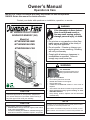
Owner’s Manual
Operation & Care
INSTALLER: Leave this manual with party responsible for use and operation.
OWNER: Retain this manual for future reference.
Contact your dealer with questions on installation, operation, or service.
NOTICE: DO NOT DISCARD THIS MANUAL
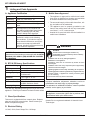
WARNING
If the information in these instructions is not followed exactly, a
fire may result causing property
damage, personal injury, or death.
MT VERNON PELLET INSERT
ADVANCED ENERGY (AE)
Model(s):
MTVERNINSAE-MBK
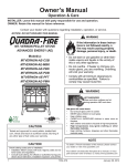
• Do not store or use gasoline or other flammable vapors and liquids in the vicinity of
this or any other appliance.
MTVERNINSAE-PMH
• Do not overfire - If heater or chimney connector glows, you are overfiring. Overfiring
will void your warranty.
MTVERNINSAE-CSB
• Comply with all minimum clearances to
combustibles as specified. Failure to
comply may cause house fire.
WARNING
HOT SURFACES!
Glass and other surfaces are hot
during operation AND cool down.
Tested and
Listed by
Portland
Oregon USA
O-T L
C
US
OMNI-Test Laboratories, Inc.
CAUTION
Tested and approved for wood pellets, shelled field
corn, wheat and black oil sunflower seeds. Burning of
any other type of fuel voids your warranty.
Hot glass will cause burns.
•
Do not touch glass until it is cooled
•
NEVER allow children to touch glass
•
Keep children away
•
CAREFULLY SUPERVISE children in same room as
fireplace.
•
Alert children and adults to hazards of high temperatures
•
High temperatures may ignite clothing or other
flammable materials.
•
Keep clothing, furniture, draperies and other flammable
materials away.
NOTE
CAUTION
Check building codes prior to installation.
• Installation MUST comply with local, regional, state and national codes and regulations.
• Consult local building, fire officials or authorities having jurisdiction about restrictions, installation inspection, and permits.
1
To obtain a French translation of this manual, please contact
your dealer or visit www.quadrafire.com
Pour obtenir une traduction française de ce manuel, s’il vous
plaît contacter votre revendeur ou visitez www.quadrafire.com
7036-187C
October 27, 2014
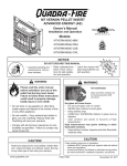
MT. VERNON AE INSERT
and Welcome to the Quadra-Fire Family!
A. Congratulations
Hearth & Home Technologies welcomes you to our tradition
of excellence! In choosing a Quadra-Fire appliance, you
have our assurance of commitment to quality, durability, and
performance.
This commitment begins with our research of the market,
including ‘Voice of the Customer’ contacts, ensuring we
make products that will satisfy your needs. Our Research
and Development facility then employs the world’s most
advanced technology to achieve the optimum opera-
tion of our stoves, inserts and fireplaces. And yet we are
old-fashioned when it comes to craftsmanship. Each unit
is meticulously fabricated and gold and nickel surfaces are
hand-finished for lasting beauty and enjoyment. Our pledge
to quality is completed as each model undergoes a quality
control inspection.
We wish you and your family many years of enjoyment in
the warmth and comfort of your hearth appliance. Thank
you for choosing Quadra-Fire.
NOTE: Clearances may only be reduced by means
approved by the regulatory authority having jurisdiction
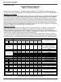
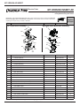
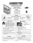
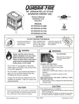
B. Sample of Serial Number / Safety Label
LOCATION: On Beaded Chain on e behind Right Side Panel
CAUTION:
HOT WHILE IN OPERATION DO NOT TOUCH, KEEP CHILDREN, CLOTHING AND FURNITURE AWAY. CONTACT MAY CAUSE SKIN
BURNS. SEE NAMEPLATE AND INSTRUCTIONS. Operate this unit only with fuel hopper lid closed. Failure to do so
may result in emission of products of combustion from the hopper under certain conditions. Maintain hopper
seal in good condition. Do not overfill hopper.
CHAUD LORS DE L'OPÉRATION. NE PAS TOUCHER. GARDEZ LES ENFANTS ET LES VÊTEMENTS LOIN DE L'ESPACE
DÉSIGNÉ DE L'INSTALLATION. LE CONTACT PEUT CAUSER DES BRÛLURES À LA PEAU. VOIR L'ÉTIQUETTE ET LES
INSTRUCTIONS. Opérez cet appareil avec le couvercle de la trémie fermé. Le défaut de ne pas suivre les instructions peut résulter,
sous certaines conditions, en une combustion des émissions des produits venant de la trémie. Ne pas remplir la trémie trop pleine.
Model
Name
ATTENTION:
SAFETY LABEL / ÉTIQUETTE DE SÉCURITÉ
R
Tested and
Listed by
Portland
Oregon USA
O-T L
Report / Rapport
#061-S-69-6
US
C
OMNI-Test Laboratories, Inc.
SERIAL NO. / NUMÉRO DU SÉRIE
007002
Mt. Vernon Pellet Insert AE
Listed Solid Fuel Room Heater/Pellet Type Insert. Also suitable for Mobile Home Appareil de chauffage inséré de combustible solide/de type de boulettes. Accepté dans
Installation. This appliance has been tested and listed for use in Manufactured l'installation dans les maisons mobiles. Cet appareil a été testé et enregistré pour l'usage
Homes in accordance with OAR 814-23-9000 through 814-23-909.
dans les Maisons Mobiles en accord avec OAR 814-23-9000 jusqu'à 814-23-909.
Test Lab &
Report No.
Tested to: ASTM E1509-04, ULC S628-93, ULC/ORD-C1482-M1990 Room Heating Pellet
Burning Type, (UM) 84-HUD FOR USE ONLY WITH PELLETIZED WOOD. SEE OWNER’S
MANUAL FOR OTHER FUEL OPTIONS.
OMNI-Test Laboratories, Inc. has determined that this appliance complies with
Canadian Standards Association (CSA) B415.1 and Title 40 of the U.S. Code of
Federal Regulations, Part 60, SubPart AAA.OMNI-Test Laboratories Accrediations:
The Standards Council of Canada, the American National Standards Institute, and the
U.S. Environmental Protection Agency.
Input Rating: 60,000 BTU/HR.
Electrical Rating: 115 VAC, 60 Hz, Start 5 Amps, Run 1.25 AMPS.
Route power cord away from unit. Do not route cord under or in front of appliance.
DANGER: Risk of electrical shock. Disconnect power supply before servicing.
Replace glass only with 5mm ceramic available from your dealer.
To start, set thermostat above room temperature, the stove will light automatically. To
shutdown, set thermostat to below room temperature. For further instruction refer to
owner's manual.
Keep viewing and ash removal doors tightly closed during operation.
A
S
M
PREVENT HOUSE FIRES
Install and use only in accordance with manufacturer's installation and operating instructions.
Contact local building or fire officials about restrictions and inspection in our area.
WARNING: FOR MOBILE HOMES: Do not install appliance in a sleeping room. An
outside combustion air inlet must be provided. The structural integrity of the mobile home
floor, ceiling and walls must be maintained.
Refer to manufacturer's instructions and local codes for precautions required for passing
chimney through a combustible wall or ceiling. Inspect and clean vent system frequently
in accordance with manufacturer's instructions.
DO NOT CONNECT THIS UNIT TO A CHIMNEY FLUE SERVING ANOTHER APPLIANCE.
Use a 3 or 4 inch (76-102mm) diameter type "L" or "PL" venting system.
E
L
Testé à: ASTM #1509-04, ULC S628-93, ULC/ORD-C1482-M1990 Room Heating. Pellet Burning Type,
UM) 84-HUD POUR USAGE AVEC LES BOULETTES DE BOIS. VOIR LE MANUAL DU PROPRIÉTAIRE
POUR D’AUTRES OPTIONS DE CARBURANT.
OMNI-Test Laboratories, Inc. a déterminé que cet appareil se conforme avec la norme de l’Association
Canadienne de normalisation (CSA) B415.1 ainsi que le Titre 40 du Code Fédéral de Régulations des
États-Unis, partie 60, sous-partie AAA. Accréditations OMNI-Test Laboratories : Le Conseil Canadien
des Normes (CCN/SCC), l’Institue des Standards Nationaux Américain (ANSI) et l’Agence de Protection
Environnemental (EPA).
Puissance de Rendement: 60,000 BTU/HR
Puissance Électrique: 115 VAC, 60 Hz, Début 5 Amps, Courir 1.25 Amps,
Éloignez le fil électrique de l'appareil. Ne pas faire passer le fil électrique au dessus ou en dessous de l'appareil.
DANGER: Il y a risque de décharge électrique. Déconnectez le fil électrique de la prise de contact avant le service.
Remplacez la vitre seulement avec une vitre céramique de 5 mm disponible chez votre fournisseur.
Pour allumer, monter la température du thermostat au dessus de la température de la pièce, le poêle s'allumera
automatiquement. Pour éteindre, descendre la température du thermostat en dessous de la température de la
pièce. Pour des instructions supplémentaires, référez vous au manuel du propriétaire. Gardez la porte d'ouverture
et la porte des cendres fermées hermétiquement durant l'opération.
P
PRÉVENTION DES FEUX DE MAISON
Installez et utilisez en accord avec les instructions d'installation et d'opération du fabricant. Contactez le bureau
de la construction ou le bureau des incendies au sujet des restrictions et des inspections d'installation dans
votre voisinage. Ne pas obstruez l'espace en dessous de l'appareil.
AVIS - Pour Les Maisons Mobiles: Ne pas installer dans une chambre à coucher. Un tuyau extérieur de
combustion d'air doit être installé et ne doit pas être obstrué lorsque l'appareil est en usage. La structure
intégrale du plancher, du plafond et des murs de la maison mobile doit être maintenue intacte.
Référez vous aux instructions du fabricant et des codes locaux pour les précautions requises pour passer une
cheminée à travers un mur ou un plafond combustibles, et les compensations maximums.
Inspectez et nettoyez la cheminée fréquemment.
NE PAS CONNECTER CETTE UNITÉ À UN CONDUIT DE CHEMINEE DESSERVANT UN AUTRE APPAREIL.
Utilitsez le système de ventilation de 3 or 4 inch (76-102mm) de diametre de type “L” ou “PL”.
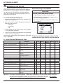
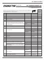
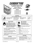
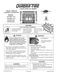
MINIMUM CLEARANCES TO COMBUSTIBLE MATERIALS
ESPACES LIBRES MINIMUM DES MATÉRIAUX COMBUSTIBLES:
COMME APPAREIL INSÉRÉ
AS A BUILT-IN UNIT
A
A Top of Hopper
B Side of Outside Skin
C Back of Hopper
Top/Rear Vent
Top/Rear Vent
Top Vent
Rear Vent
D Vent Pipe to Combustible Top/Rear Vent
E Cast Side to Side Wall Top/Rear Vent
Garniture
de façade
MANTEL MANTEAU
SIDE WALL
MUR LATÉRAL
B
C
A
C
A Des Conduits Du Haut/Arrières:
B Des Conduits Du Haut/Arrières:
C Des Conduits Du Haut:
Arrières
D Des Conduits Arrières/Du Haut
E Côté de Fonte au Mur Latéral:
3 in. (76mm)
2 in. (51mm)
7.5 in. (191mm)
2.75 in. (70mm)
3 in. (76mm)
6 in. (152mm)
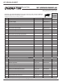
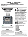
Masonry or Zero Clearance Dégagement de la maçonnerie ou Dégagement zéro*
Face Trim
A Insert side to combustible / Insérez le côté au mur combustible latéral
B Insert top to face trim / Insérez le dessus de la garniture de façade
C Insert side to face trim / Insérez le côté de la garniture de façade
D Hearth extension from door opening / Prolongement d’âtre depuis l’ouverture de la porte devant
E Hearth extension from side of door opening / Prolongement d’âtre depuis le côté
6 in.
0 in.
0 in.
6 in.
6 in.
152mm
0mm
0mm
152mm
152mm
de l’ouverture de la porte
*When constructing floor protection for your pellet appliance, any parts or materials used, must be non-combustible.
E
D
* Lors de la construction de protection de sol pour votre appareil à granules, toute pièces ou matériaux utilisés, doivent être incombustibles.
DO NOT REMOVE THIS LABEL
Manufactured by: Fabriqué par:
1445 North Highway, Colville, WA 99114
www.quadrafire.com
2
D
3 in. (76mm)
B
B
2 in. (51mm)
C
7.5 in. (191mm)
2.75 in. (70mm)
E
3 in. (76mm)
0 in. Clearance To Exposed Section and Face Trim / Espace libre
6 in (152mm)
de 0 mm de la section exposée et de la garniture du devant.
See manual for mantel clearances.
Serial No.
2012 2013 2014
JAN
NE PAS ENLEVER L'ÉTIQUETTE
FEB MAR APR MAY JUNE JULY AUG SEPT OCT NOV DEC
Made in U.S.A. of US and
imported parts.
U.S ENVIRONMENTAL PROTECTION AGENCY
This model is exempt from EPA certification under 40 CFR 60.531 by definition [Wood Heater (A) “air-to-fuel ration”].
7036-187C
Mfg. Date
Fabriqué aux États-Unis-d’Amérique par des
pièces d’origine américaine et pièces
importées.
7036-137H
October 27, 2014
MT. VERNON AE INSERT
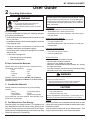
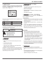
Safety Alert Key:
•
DANGER! Indicates a hazardous situation which, if not avoided will result in death or serious injury.
•
WARNING! Indicates a hazardous situation which, if not avoided may result in death or serious injury.
•
CAUTION! Indicates a hazardous situation which, if not avoided, may result in minor or moderate injury.
•
NOTICE: Indicates practices which may cause damage to the appliance or to property.
TABLE OF CONTENTS
A. Congratulations..................................................................2
B. Sample of Serial Number / Safety Label............................2
C. Warranty Policy .................................................................4
1 Listing and Code Approvals ............. 6
A.
B.
C.
D.
E.
Appliance Certification ......................................................6
BTU & Efficiency Specifications........................................6
Glass Specifications .........................................................6
Electrical Rating................................................................6
Mobile Home Approved .................................................... 6
2 Operating Instructions ...................... 7
A. Fire Safety .........................................................................7
B. Non-Combustible Materials ..............................................7
C. Combustible Materials ......................................................7
D. Fuel Material and Fuel Storage ........................................7
E. General Operating Information .........................................8
F. Before Your First Fire ........................................................9
G. Filling the Hopper with Fuel ...............................................9
H. Starting Your First Fire .....................................................9
I. Fire Characteristics & Flame Height Adjustment................9
J. Battery Back-up System (Optional) ...................................10
K. Clear Space ......................................................................10
L. Ignition Cycles ....................................................................11
M. Insert Removal ..................................................................12
N. Frequently Asked Questions.............................................13
4 Maintenance and Service ................ 22
A.
B.
C.
D.
Proper Shutdown Procedure ............................................22
Quick Reference Maintenance Chart................................22
General Maintenance and Cleaning .................................23
High Ash Fuel Content Maintenance ................................27
5 Troubleshooting Guide.................... 28
6 Service Parts Replacement ............. 29
A. Baffle Removal ................................................................29
B. Glass Replacement .........................................................29
C. Convection Blower Replacement ....................................30
7 Reference Materials ......................... 31
A. Component Functions .......................................................31
B. Component Locations ........................................................33
C. Exploded Drawings............................................................34
D. Service Parts List...............................................................35
E. Homeowner’s Notes ..........................................................42
3 Wall Control Operating Instructions14
A. Introduction .......................................................................14
B. Language Selection ..........................................................14
C. The Main Screen ..............................................................14
D. General Information About Using the Wall Control ...........15
E. The Main Menu .................................................................15
F. Quick Start Guide ...............................................................19
G. Service Information ..........................................................21
H. Error Codes .......................................................................21
I. Battery Back-up System (Optional) ....................................21
300 Watt Igniters come installed in brand new Mt. Vernon AE
units and are for pellet fuel only. The 380 Watt Igniter is required
for burning multi-grain fuels and is included in the component
pack. Multi-fuels include, corn, sunflower seeds, and wheat.
October 27, 2014
7036-187C
3
MT. VERNON AE INSERT
C. Warranty Policy
Hearth & Home Technologies Inc.
LIMITED LIFETIME WARRANTY
Hearth & Home Technologies Inc., on behalf of its hearth brands (”HHT”), extends the following warranty for
HHT gas, wood, pellet, coal and electric hearth appliances that are purchased from an HHT authorized dealer.
WARRANTY COVERAGE:
HHT warrants to the original owner of the HHT appliance at the site of installation, and to any transferee taking ownership
of the appliance at the site of installation within two years following the date of original purchase, that the HHT appliance
will be free from defects in materials and workmanship at the time of manufacture. After installation, if covered components manufactured by HHT are found to be defective in materials or workmanship during the applicable warranty period,
HHT will, at its option, repair or replace the covered components. HHT, at its own discretion, may fully discharge all of its
obligations under such warranties by replacing the product itself or refunding the verified purchase price of the product
itself. The maximum amount recoverable under this warranty is limited to the purchase price of the product. This warranty
is subject to conditions, exclusions and limitations as described below.
WARRANTY PERIOD:
Warranty coverage begins on the date of original purchase. In the case of new home construction, warranty coverage
begins on the date of first occupancy of the dwelling or six months after the sale of the product by an independent,
authorized HHT dealer/ distributor, whichever occurs earlier. The warranty shall commence no later than 24 months
following the date of product shipment from HHT, regardless of the installation or occupancy date. The warranty period for
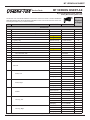
parts and labor for covered components is produced in the following table.
The term “Limited Lifetime” in the table below is defined as: 20 years from the beginning date of warranty coverage for
gas appliances, and 10 years from the beginning date of warranty coverage for wood, pellet, and coal appliances. These
time periods reflect the minimum expected useful lives of the designated components under normal operating conditions.
Warranty Period
Parts
Labor
1 Year
2 years
HHT Manufactured Appliances and Venting
Gas
X
X
Wood
X
X
X
3 years
Pellet
EPA
Wood
Coal
X
X
X
X
X
X
X
X
X
Components Covered
Electric Venting
X
X
All parts and material except as
covered by Conditions,
Exclusions, and Limitations
listed
Igniters, electronic components,
and glass
Factory-installed blowers
Molded refractory panels
Firepots and burnpots
X
5 years
1 year
7 years
3 years
10
years
1 year
X
Limited
3 years
Lifetime
X
X
X
X
X
90 Days
X
X
X
X
X
X
X
X
Castings and baffles
X
X
Manifold tubes,
HHT chimney and termination
Burners, logs and refractory
Firebox and heat exchanger
X
X
All replacement parts
beyond warranty period
See conditions, exclusions, and limitations on next page.
4
7036-187C
October 27, 2014
MT. VERNON AE INSERT
WARRANTY CONDITIONS:
!
"
"
WARRANTY EXCLUSIONS:
^
!
*
N
!!
!!!
!!
*
@
%
^!!"!
"!
!!!
Z
*!
!
N
^_`q
!
!
!
!
;_{q
;_|q
;_}q
!!!
!
!!
~
;_q
!+!
!
!"#
!
*
;_q
;_q
*
;_q*
;
~
_q
?#!
%
#*
'
*'
!
!
This warranty is void if:
#
!
!
$
#
!!
!
!!
"
%
!
!
LIMITATIONS OF LIABILITY:
'*
'
!
!*
!
!
!
!
!
!
+8
*
+!
;
!
<=<>$
<<=<?>@$KN<NOQRU!Z[<8?$<=>@<88U@@?<8$<@?<U@@?Q
8><\<N<@<?<N]@$?$\?QZ>R<NU@@?Q8RZ<N$N]@$?$\<
<=>@<88<NU@@?Q8><\<NO$K<
October 27, 2014
7036-187C
5
MT. VERNON AE INSERT
1
Listing and Code Approvals
A. Appliance Certification
Model
E. Mobile Home Approved
• This appliance is approved for mobile home installations when not installed in a sleeping room and when
an outside combustion air inlet is provided.
Mt. Vernon Pellet Insert AE
Laboratory
OMNI Test Laboratories, Inc.
Report No.
061-S-69-6
Type
Solid Fuel Room Heater/Pellet Type
Insert
Standard
ASTM E1509-04, ULC S628-93 and
ULC/ORD-C1482-M1990 Room Heater
Pellet Fuel Burning type and (UM)
84-HUD, Mobile Home Approved.
FCC
• The structural integrity of the mobile home floor, ceiling, and walls must be maintained.
• The appliance must be properly grounded to the
frame of the mobile home and use only Listed pellet
vent Class “L” or “PL” connector pipe.
• Outside Air Kit, part OAK-ACC must be installed in a
mobile home installation.
Complies with Part 15 of FCC Rules.
Operation is subject to the following
two conditions: (1) this device may not
cause harmful interference, and (2) this
device must accept any interference
received, including interference that may
cause undesired operation.
WARNING
Fire Risk.
NOTICE: This installation must conform with local codes. In
the absence of local codes you must comply with the ASTM
E1509-04, ULC S628-93, (UM) 84-HUD and ULC/ORDC-1482-M1990.
Hearth & Home Technologies disclaims any
responsibility for, and the warranty will be voided by,
the following actions:
*BTU Input:
14,620 - 60,200 / hr
Efficiency:
Up to 86.5%
Heating Capacity:
Up to 3,000 square feet depending
on climate zone
• Installation and use of any damaged appliance.
• Modification of the appliance.
• Installation other than as instructed by Hearth & Home
Technologies.
• Installation and/or use of any component part not approved by
Hearth & Home Technologies.
• Operating appliance without fully assembling all components.
• Operating appliance without legs attached (if supplied with unit).
• Do NOT Overfire - If appliance or chimney connector glows,
you are overfiring.
Vent Size:
3” or 4” Type “L” or “PL”
Any such action that may cause a fire hazard.
Hopper Capacity:
56 lbs +/-5 lbs
Fuels:
Pellets, Shelled Field Corn, Wheat
and Black Sunflower Seeds
Shipping Weight:
425 lbs
B. BTU & Efficiency Specifications
Emissions Rating: EPA Compliance
*BTU will vary, depending on the type of fuel you use in your
appliance. Consult your Quadra-Fire dealer for best results.
C. Glass Specifications
This stove is equipped with 5mm ceramic glass. Replace
glass only with 5mm ceramic glass. Please contact your
dealer for replacement glass.
Improper installation, adjustment, alteration, service or
maintenance can cause injury or property damage.
For assistance or additional information, consult a qualified
installer, service agency or your dealer.
NOTE: Hearth & Home Technologies, manufacturer of
this appliance, reserves the right to alter its products, their
specifications and/or price without notice.
Quadra-Fire is a registered trademark of Hearth & Home
Technologies.
D. Electrical Rating
115 VAC, 60 Hz, Start 5 Amps, Run 1.25 Amps
6
7036-187C
October 27, 2014
MT. VERNON AE INSERT
2
User Guide
Operating Instructions
300 Watt Igniters come installed in brand new Mt. Vernon
AE units and are for pellet fuel only. The 380 Watt Igniter
is required for burning multi-grain fuels and is included in
the component pack. Multi-fuels include, corn, sunflower
seeds, and wheat.
WARNING
Fire Risk.
•
Do not operate appliance before reading and
understanding operating instructions.
•
Failure to operate appliance properly may cause a
house fire.
A. Fire Safety
To provide reasonable fire safety, the following should be
given serious consideration:
• Install at least one smoke detector and CO monitor on each
floor of your home.
• Locate detectors away from the heating appliance and close
to the sleeping areas.
• Follow the detector’s manufacturer’s placement and
installation instructions and maintain regularly.
• Conveniently locate a Class A fire extinguisher to contend
with small fires.
•
In the event of a hopper fire:
• Evacuate the house immediately.
• Notify fire department.
B. Non-Combustible Materials
Material which will not ignite and burn, composed of any
combination of the following:
- Steel
- Plaster
- Brick
- Iron
- Concrete
- Tile
- Glass
- Slate
Materials reported as passing ASTM E 136, Standard
Test Method for Behavior of Metals, in a Vertical Tube
Furnace of 750° C.
Fuel Material
• Made from sawdust or wood by-products
• Shelled field corn & other biomass fuels
• Depending on the source material it may have a high or
low ash content.
Higher Ash Content Material
• Hardwoods with a high mineral content
• Fuel that contains bark
• Standard grade pellets, high ash pellets, corn and other
biomass fuels
Lower Ash Content Material
• Softwoods
• Fuels with low mineral content
• Premium grade pellets
Shelled Field Corn
• Must be 15% or less moisture content.
• Must be clean and free from debris
• Never burn corn straight from the field
• Stalk parts, excessive fines and cob remnants, etc. will clog
the auger mechanism
• Corn with excessive grain dust must be screened by sifting
with 3/16 inch (4.7mm) mesh screening
WARNING
Risk of Chemical Poisoning!
Do NOT burn treated seed corn
• Chemical pesticides are harmful or fatal if swallowed
• Burning treated seed corn will void your warranty
C. Combustible Materials
Material made of/or surfaced with any of the following
materials:
- Wood
- Compressed Paper
- Plant Fibers
- Plastic
- Plywood/OSB
- Sheet Rock (drywall)
Any material that can ignite and burn: flame proofed or not,
plastered or un-plastered.
CAUTION!
Do not burn fuel that contains an additive; (such as soybean oil).
• May cause hopper fires
• Damage to product may result
Read the ingredients list on the package. If you are buying corn or
wheat the only ingredient that should be listed is corn or wheat.
Clinkers
D. Fuel Material and Fuel Storage
Pellet fuel quality can greatly fluctuate. This appliance has
been designed to burn a wide variety of fuels, giving you the
choice to use the fuel that is most economical in your region.
Hearth & Home Technologies strongly recommends only using
Pellet Fuel Institute (PFI) certified fuel.
October 27, 2014
Minerals and other non-combustible materials such as sand
will turn into a hard, glass-like substance called a clinker when
heated in the firepot.
Trees from different areas will vary in mineral content. That
is why some fuels produce more clinkers than others.
7036-187C
7
MT. VERNON AE INSERT
E. General Operating Information
Size
• Pellets are either 1/4 inch or 5/16 inch (6-8mm) in diameter
• Length should be no more that 1-1/2 inches (38mm)
• Pellet lengths can vary from lot to lot from the same
manufacturer
• Due to length variations, the flame height (feed rate) may
need adjusting occasionally. See page 9 for instructions.
Performance
• Higher ash content requires the ash drawer to be emptied
more frequently
• Hardwoods require more air to burn properly
• Set wall control to “Utility Pellet” if the firepot and ash pan
are filling quickly. This will cause the auto-clean system
to empty the firepot more often.
• Premium wood pellets produce the highest heat output.
• Burning pellets longer than 1-1/2 inches (38mm) can cause
an inconsistent fuel feed rate and/or missed ignitions.
Read and understand the Thermostat Wall Control
manual for detailed operating instructions. The wall control is an integral part of how to operate this appliance.
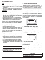
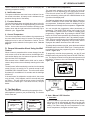
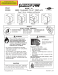
1. Thermostat Wall Control - Automatic Setting
The appliance is like most modern furnaces; when the
thermostat wall control calls for heat, your appliance will
automatically light and deliver heat.
When the room is up to temperature and the wall control is
satisfied the appliance will shut down.
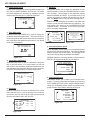
In the automatic setting the heat output level is controlled by
the wall control. Select “Automatic” on the AUTO/MANUAL
screen. Figure 8.1.
AUTO/MANUAL SETTINGS
Automatic
Manual
Off
We recommend that you buy fuel in multi-ton lots whenever
possible. However, we do recommend trying various brands
before purchasing multi-ton lots to ensure your satisfaction.
Changing to Different Fuel Type
Figure 8.1
• Empty the hopper of the previous fuel
• Thoroughly vacuum hopper before filling with the new fuel
• Select the appropriate setting on the FUEL SELECTION
screen on the thermostat wall control
The burn rate, BTU content and heat output will all vary
depending on the fuel selected.
Storage
2. Thermostat Wall Control - Manual Setting
When you select “Manual” on the AUTO/MANUAL screen the
appliance will still automatically turn on and off according to
the temperature setting.
However, you will be able to manually control the heat output
levels. Adjust the heat output levels by using the HEAT
OUTPUT LEVEL screen. Figure 8.2.
• Wood pellets should be left in their original sealed bag until
using to prevent moisture absorption.
• Shelled corn, wheat or sunflower seeds should be stored in
a tight container to prevent it from absorbing moisture from
damp or wet floors.
Medium
• This will also prevent rodents from becoming a problem.
• Do not store any pellet fuel within the clearance requirements
or in an area that would hinder routine cleaning and
maintenance.
CAUTION
Tested and approved for wood pellets, shelled field corn,
wheat and black oil sunflower seeds. Burning of any other
type of fuel voids your warranty.
Figure 8.2
3. Auto-Clean Firepot System
Your appliance is equipped with an automatic firepot cleaning
system that will change the frequency of cleaning based on
the fuel being burned.
The auto-clean system will clean itself immediately on initial
plug in. If there is a power outage, as soon as power is
restored it will recycle and clean itself if there is no fire in the
firepot.
NOTE: User is responsible for removing the ash from the
ash drawer.
CAUTION
Hot while in operation. Keep children, clothing and furniture
away. Contact may cause skin burns.
8
7036-187C
October 27, 2014
MT. VERNON AE INSERT
F. Before Your First Fire
•
First, make sure your appliance has been properly installed
and that all safety requirements have been met.
•
Pay particular attention to the fire protection, venting and
thermostat wall control installation instructions.
•
Double check that the ash pan, hopper and firebox are
empty and then close the firebox door.
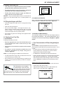
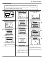
FUEL SELECTION
Corn
Utility Pellet
Softwood Pellet
Sunflower Seeds
Wheat
Hardwood Pellet
DONE
SELECT
Figure 9.1
NOTICE: The tip of thermocouple must be in contact with the
inside end of the thermocouple cover or missed ignitions can
occur.
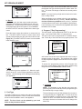
2. Comfort Level Selection
G. Filling the Hopper with Fuel
Once your fuel is selected, select the temperature at the desired
setting on the SET COMFORT LEVEL screen. Figure 9.2.
•
Check the hopper and make sure it is empty before filling
with fuel.
•
Open the cast top hopper lid.
•
Do not over fill the hopper. The hopper lid must be completely closed to maintain proper vacuum and for the feed
motor to operate. An error ICON will appear on the wall
control if the hopper lid is not properly closed.
•
Do not leave any part of the fuel bag on the appliance after
filling hopper.
H. Starting Your First Fire
1. Fuel Selection
Figure 9.2
3. Automatic or Manual Setting
The automatic setting will control the heat output based on
the comfort level selection. The manual setting allows you to
manually control the heat output settings. See page 11, Ignition
Cycles.
To start your first fire, you must:
• Select the appropriate fuel on the FUEL SELECTION screen
on the thermostat wall control to match the fuel you have
chosen to burn.
• If the proper fuel is not selected your appliance will not operate
properly.
I. Fire Characteristics & Flame Height Adjustment
(Feed Rate) A properly adjusted fire will have an active
• For example, if you have selected wood pellets and you are
burning corn, the appliance may not light, it may go out or
overfeed. Figure 9.1.
flame pattern and the flame will rise and fall somewhat. This is
normal.
• On HIGH setting, the flame will extend approximately 8
inches (203mm) out of the firepot. If it is not 8 inches
(203mm) tall, increase the flame height.
NOTE: If you are lighting your appliance for the first time:
•
On MEDIUM or LOW setting the flame will be shorter.
•
The feed tube will be empty and it can take some time to fill
it with fuel before you will see a fire
•
•
Put a handful of fuel in the firepot (priming) to speed up the
process. You can also do this when you have run completely out of fuel.
Reduce the flame height if the fire has tall flames with black
tails and seems somewhat lazy. This may also indicate
that the firepot and/or heat exchanger needs to be cleaned.
Refer to Section 4 for Maintenance and Cleaning Instructions.
Adjusting the Flame Height (Feed Rate)
• Set your appliance to “MANUAL” mode on the wall control.
300 Watt Igniters come installed
in brand new Mt. Vernon AE units
and are for pellet fuel only. The 380
Watt Igniter is required for burning
multi-grain fuels and is included in the component pack.
Multi-fuels include, corn, sunflower seeds, and wheat.
•
Set the heat output level to HIGH.
•
Adjust the flame height using the “FLAME HEIGHT ADJUST” screen on the wall control. Figure 9.3.
Figure 9.3
October 27, 2014
7036-187C
9
MT. VERNON AE INSERT
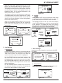
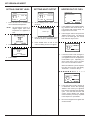
J. Battery Back-up System (Optional)
Wall Control Display
CAUTION!
The wall control will display the battery icon when operating
in the battery back-up mode. Figure 10.2
• Hook up to battery terminals BEFORE you plug battery
into appliance.
“Maint Burn” will display when
the thermostat has reached the
set room temperature and will
run on low until it reaches its
auto-clean cycle time.
• Damage to internal electronic components may occur.
The appliance has been designed to operate on an optional
battery back-up system.
If you have frequent power outages in your region, hook
the appliance up to a 12 volt battery and it will automatically
switch to battery power in the event of a power failure. The
12 volt power cord, sold as a separate accessory, does not
charge the battery.
MAINT BURN
73
WARNING! Risk of Injury!
MENU
• Blowers may continue to run and would be exposed to
human contact.
Figure 10.2
• A battery icon appears on your wall control to let you know
you are now operating on battery power. Figure 10.2.
K. Clear Space
• Use only approved fire starting gel to start the fire.
HEAT OUTPUT
Mantel: Avoid placing candles and other heat-sensitive
objects on mantel or hearth. Heat may damage these objects.
NOTICE: Clearances may only be reduced by means approved by the regulatory authority having jurisdiction.
• The high burn rate is no longer available on battery backup.
WARNING
• Each level drops down one level, i.e the high burn becomes medium-high burn and so on.
• If the battery charge falls below 10 volt it can no longer
sustain the appliance operation and the appliance will
shut down. Figure 10.1. You must disconnect and reconnect the battery to start it up again.
Set at: 73
Battery icon.
Operating on Battery Back-Up
• The fire must be manually lit as the appliance will no longer automatically light. Follow the instructions in the Wall
Control Manual.
12:30 PM
Fire Risk.
Do NOT place combustible objects in front of the
appliance. High temperatures may ignite clothing,
furniture or draperies. Maintain a minimum clearance of 3 feet (914mm) in front of appliance.
Recommended Battery
• 12 volt deep cycle battery, (i.e., marine or RV type).
WARNING
• A 12 volt battery cable is available through your local
dealer.
•
13 Volts
Figure 10.1
12 Volts
11 Volts
Battery
Below
10 Volts
•
•
•
•
10
7036-187C
Fire Risk.
Keep combustible materials, gasoline and other
flammable vapors and liquids clear of appliance.
• Do NOT store flammable materials in the
appliance’s vicinity.
DO NOT USE GASOLINE, LANTERN FUEL, KEROSENE,
CHARCOAL LIGHTER FLUID OR SIMILAR LIQUIDS TO
START OR “FRESHEN UP” A FIRE IN THIS HEATER.
DO NOT BURN GARBAGE OR FLAMMABLE FLUIDS
SUCH AS GASOLINE, NAPHTHA OR ENGINE OIL.
DO NOT USE CHEMICALS OR FLUIDS TO START THE
FIRE.
Keep all such liquids well away from the heater while it is in
use.
Combustible materials may ignite.
October 27, 2014
MT. VERNON AE INSERT
L. Ignition Cycles
2. Soft Start Cycle (SS-Low / SS-Med)
The appliance engine is controlled by the digital thermostat
wall control. The digital display on the wall control will tell
you what your appliance is doing in the upper left corner
(System Status). Figure 11.1.
Once the fire is lit:
• The appliance moves into the low soft-start cycle as it
continues to build the fire
• More fuel will be added
• As the fire builds, the appliance will change to medium
soft-start mode
System Status
• The heating cycle begins
12:30 PM
READY
Set at: 73
73
3. Heating Cycle ( Auto / Man - L, ML, M, MH, H)
MENU
HEAT OUTPUT
There are two choices in the Automatic / Manual menu of
how your appliance will operate:
Figure 11.1
Automatic Mode
Every time the thermostat calls for heat, the appliance steps
through five cycles:
1
Start-Up Cycle
4 Shutdown Cycle
2
Soft-Start Cycle
5 Auto-Clean Cycle
3
Heating Cycle
• The wall control will turn the heat output level up or down
depending on how far the room temperature is from the
desired temperature
• The digital display will read AUTO:M, i.e. automatic-medium level
• As the room temperature approaches the desired temperature, the appliance will turn down to lower settings
The duration and characteristics of these cycles may be different with each type of fuel selected.
WARNING
• When the home reaches your set temperature, the appliance will go into the shutdown cycle
Manual Mode
• Set the heat output setting from the main screen
• The right bottom button will read HEAT OUTPUT
• You can operate the appliance from any of the 5 levels
Fire Risk.
Do NOT operate appliance:
• With appliance door open
• With firepot floor open
• With ash pan removed
• On the lowest level (MAN: L) the appliance will stay on
longer, burn less fuel per hour, and will take longer to
bring the home up to your desired temperature
• On the highest setting (MAN:H) the appliance will burn
more fuel per hour, and bring your home up to temperature more quickly
1. Start-Up Cycle
During this cycle:
• Igniter turns on for 90 seconds to heat up the air in the
firepot
• Combustion blower starts
• Vacuum switch comes on
• In Manual mode the heat output does not change but
will stay at the setting you chose until the comfort level
is reached (meaning the thermostat has been satisfied).
Turn to OFF to stop operation.
• Feed motor turns on adding fuel to the firepot and the
appliance waits for the fire to start
4. Shutdown Cycle
The duration of start-up depends on the type and quality of
fuel used. It is normal to see some smoke during the ignition process as moisture evaporates and the fuel lights. The
smoke will stop once the fire starts.
• Appliance will stop feeding fuel and allow the fire to diminish
Once your home has reached your set temperature:
• Convection blower will continue to run until the appliance
cools to appropriate temperature
•
October 27, 2014
Appliance will begin the auto-clean cycle
7036-187C
11
MT. VERNON AE INSERT
5. Auto-Clean Cycle
WARNING
The firepot auto-clean system will cycle:
• When the appliance is first plugged in
• When the house reaches temperature and the appliance
shuts down
• At prescribed intervals, depending on the type of fuel selected
• When starting up after an electrical interruption
If your appliance is running and the auto-clean cycle is initiated, the appliance will revert to shutdown cycle.
• The floor of the firepot will open and dump the ash into
the ash pan
• It takes approximately 2 minutes to complete the auto-clean cycle
• The floor will then shut, and if the thermostat is still calling
for heat, the fire will start again
• During this auto-clean cycle, the convection blower may
continue to run. The combustion blower will continue to
run.
Fire Risk
Do NOT operate appliance:
• With appliance door open.
• With firepot floor open.
Do NOT store fuel:
• Closer than required clearances to combustibles to appliance.
• Within space required for loading or ash removal.
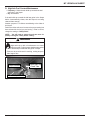
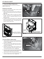
M. Insert Removal
In the case that service or inspection is required the unit may
need to be removed from the wall.
1. Unit must be unplugged before removal of unit is possible.
Unplug the unit from its power source.
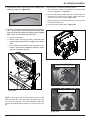
2. Remove insert surround from unit, to ease the process of
removal.
3. Unclip the exhaust transition from the exhaust outlet in the
back of the unit. This is what connects the venting to the unit.
Removal of the clips will allow you to remove the unit from the
wall without damaging or adjusting the venting.
4.
Slide unit from the wall and rotate either direction as needed.
Additional Screen Messages:
READY It is telling you that the home is up to temperature
and doesn’t need any heat.
- - - - - The screen will show 5 dashes when the wall
control and the control board are NOT communicating with
each other. Check that the wiring on the thermostat is properly connected.
MAINTENANCE BURN This indicates the appliance is
operating on battery backup, prior to the auto-clean. The
maintenance burn will keep the system from shutting down
as the appliance will not automatically re-light in battery
back-up mode.
OFF The AUTO/MANUAL SETTING screen has been set
to OFF. Set the appliance to OFF when performing periodic
maintenance to prevent an unexpected startup.
BLANK SCREEN The ON/OFF switch may be in OFF
position. Turn to ON position.
12
7036-187C
October 27, 2014
MT. VERNON AE INSERT
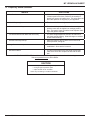
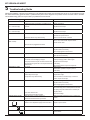
N. Frequently Asked Questions
ISSUES
SOLUTIONS
1. Metallic noise
1. Noise is caused by metal expanding and contracting as
it heats up and cools down, similar to the sound produced by a furnace or heating duct. This noise does not
affect the operation or longevity of your appliance.
2.
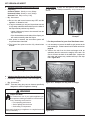
Ash build-up on glass
2. This is normal. Clean the glass.
3.
Glass has turned dirty
3. Excessive build up of ash. The lower burn settings will
produce more ash, the higher burn settings produce
less. The more it burns on low the more frequent cleaning of the glass is required.
4.
Fire has tall flames with black tails and is lazy
4. The flame height adjustment needs to be reduced or
the firepot needs cleaning. Heat exchanger or exhaust
blower needs cleaning.
5.
Excessive smokey start-up
5. Either the firepot is dirty or there is too much fuel at
start-up and not enough air.
6.
Large flame at start-up
6. This is normal. Flame will settle down once the fire is
established. Some smoke is normal.
7.
Mechanical Noise
7. The floor of the firepot in the auto-clean system may
make some noise as it scrapes the ash into the ash
pan.
CONTACT YOUR DEALER for additional information regarding operation and troubleshooting.
Visit www.quadrafire.com to find a dealer.
CAUTION
Odors and vapors released during initial operation.
• Curing of high temperature paint.
• Open windows for air circulation.
Odors may be irritating to sensitive individuals.
October 27, 2014
7036-187C
13
MT. VERNON AE INSERT
3
Wall Control Operating Instructions
A. Introduction
b. SS-LOW or SS-MED (SS = soft start)
Welcome to the Quadra-Fire family. This manual will help
you understand and operate the wall control attached to
your new pellet appliance.
Indicates the soft-start portion of the lighting sequence. In
these stages the fire begins to gradually build to operating
temperature.
The Quadra-Fire Wall Control is not just a traditional thermostat, but an integral part of the pellet appliance system.
While it has many of the features one would expect from
an advanced thermostat, including programmable setback
capabilities and current temperature display, it also indicates
the system’s current operating cycle and state. It does this
by communicating with the appliance via a wired connection.
c. AUTO: (x) or MAN: (x) (x) = heat output level
Additionally, it allows you to set parameters that will optimize
the performance of your pellet appliance system. These parameters are accessed with an easy to navigate menu system.
Indicates that the system is turned on and is functioning
normally, but there is no call for heat (the room temperature is not below the set temperature).
B. Language Selection
The language selection function is under the USER
SETTINGS found on pages 18. Please refer to that
section for complete detailed instructions.
The key to being comfortable while operating your new wall
control is to familiarize yourself with the main screen. The
main screen shows, at a glance, the status of the system,
the most important settings and the current temperature.
Additionally, the main screen indicates with simple icons
many user actions required to keep your appliance working
as intended. Figure 14.1.
READY
Current
Temperature
73
MENU
d. READY
e. SHUTDOWN
Indicates the system is shutting down, either because it
is no longer calling for heat or the maximum burn time
has been reached and the system must run an auto-clean
cycle.
f. AUTO-CLEAN
Indicates the system is running the firepot auto-clean cycle.
C. The Main Screen
System Status
Indicates both the operating cycle (automatic or manual)
and the current heat output level. The heat output level
will be “H” high, “MH” medium high, “M” medium, “ML” medium low and “L” low.
Current Time
HEAT OUTPUT
Indicates the system has been shut down by the user.
h. MAINT BURN (Battery Back-up Only)
The maintenance burn is to keep the system from shutting
down when operating on battery backup. The appliance
will not automatically re-light in battery back-up mode.
2. Current Time
12:30 PM
Set at: 73
g. OFF
Current Set
Temperature
Notifications
Icons
Function Labels for the Function Buttons
Indicates the current time. The time is used for the programmable setback features of the wall control.
3. Set Temperature
Indicates the current set temperature. It will change automatically as the control progresses through the 7 day setback program. If the wall control is in HOLD TEMP cycle the
Figure 14.1
1. System Status Codes
The status area is used to indicate the current status of the
system. It indicates if the system is running in automatic or
manual cycle, if it is turned on or off and where it is in the
operating sequence.
Hopper Lid Open
Door Open
Low Fuel
Operating on Optional Battery Backup
a. START-UP
Indicates that the appliance is in start-up cycle and is in
the process of lighting an initial charge of fuel.
Fully Charged
2/3 Charge
Battery
1/3 Charge
No Charge
Figure 14.2
14
7036-187C
October 27, 2014
MT. VERNON AE INSERT
“Set at:” indication will change to “Hold at:” and displays the
operating temperature setting.
4. Notification Icons
The system notification area uses icons to indicate if an action needs to be taken. In battery mode it indicates the approximate charge level of the battery.
5. Function Buttons
The function buttons have two labels above them in the display area. Their labels can change depending on the menu
screen. On the main screen the left button will bring up the
system menu and the right button has functionality only in
MANUAL cycle. Figure 15.2.
6. Current Temperature
The current temperature area indicates the temperature of
the room where the wall control is located. The temperature
displayed can be in units of Fahrenheit or Celsius. The desired units can be selected via the system menu. See see
page 17.
D. General Information About Using the Wall
Control
When a button is pressed and the screen changes from the
main screen to one of the other screens, the backlight will illuminate the display area. As buttons are pressed, the backlight continues to be illuminated.
Most screens have a DONE button which can be used to
return to the previous screen ultimately returning to the main
screen.
1. Set Comfort Level (Temperature)
The most basic operation of the wall control is to turn the
appliance on or off depending on the requirement for heat.
From the main screen, the SET COMFORT LEVEL screen
can be activated by pressing the UP or DOWN button on the
right side of the display area.
The first time either button is pressed the display changes to
the SET COMFORT LEVEL screen and shows the current
set temperature. Subsequent presses or holding the UP or
DOWN button will change the set temperature. Figure 15.2.
You can override the programming either permanently or
temporarily. The HOLD TEMP button (lower right) on the
SET COMFORT LEVEL screen is used to override preset
programming. Figure 15.3. By pressing the HOLD TEMP
button, the current set temperature will permanently override
any programmed temperature in the 7 day setback programming. This is a convenient way of overriding a program when
your schedule changes temporarily and you don’t want to
reprogram the setback functions on the wall control.
To release the permanent override, press the button labeled
RESUME when in the HOLD TEMP cycle. Pressing the button again will resume the programming at the next program
interval. Figure 15.4.
To temporarily override the programming, use the UP and
DOWN buttons only and do not press the HOLD TEMP button. The display will show how long the new temperature will
hold before it returns to the next scheduled programming.
Figure 15.3.
Buttons
The wall control will automatically revert back to the starting
screen if there is no activity for 15 seconds except for the
CONFIRM FUEL CHANGE screen. The main screen will be
illuminated for an additional 10 seconds and the backlight
will shut off.
Up
Down
Function Buttons
If the wall control is subjected to a static shock, the screen
may go blank. If this happens, wait 25 seconds and press
any button. This will reset the screen restore functionality
and turn on the back light. If this does not work, call your
dealer.
Figure 15.2
SET COMFORT LEVEL
ºF
74
ON HOLD
DONE
E. The Main Menu
The menu is the heart of customizing the operation of the
pellet appliance system to your personal liking. The choices
on this menu are:
Figure 15.3
RESUME
Figure 15.4
2. Auto / Manual / Off Selection
a. Automatic
MENU
Set Comfort Level
Auto/Manual/Off
Fuel Type
User Settings
MENU
Program
Set Day/Time
Set Date
Service Info
In the AUTOMATIC cycle the wall control will turn the appliance on and off automatically and also turns the heat
output level up or down depending on the temperature
setting. The further away the room temperature is from
the set temperature, the higher the heat output.
Figure 15.1
October 27, 2014
7036-187C
15
MT. VERNON AE INSERT
To select a fuel type, use the UP/DOWN buttons to scroll to
the desired fuel type and then press the button under “Select”. The arrow will change to indicate the currently selected fuel.
AUTO/MANUAL SETTINGS
Automatic
Manual
Off
NOTE: If you are burning a high ash fuel set the fuel selection to “Utility Pellets”.
Figure 16.1
b. Manual
In MANUAL cycle, the heat output remains the same
regardless of the difference between the set and room
temperatures. The wall control will function as a simple
on/off thermostat. When the system is set to MANUAL
the HEAT OUTPUT selection is added in the lower right
corner.
Press the button under this selection to access this feature. The HEAT OUTPUT screen is used to set the level
of heat produced whenever the wall control calls for heat.
Figure 16.3. The HEAT OUTPUT screen is not accessible
in AUTOMATIC cycle.
When purchasing corn or wheat to burn in your appliance,
read the ingredient label very carefully. Do NOT purchase
fuel that contains any additives such as oils (i.e. soybean
oil) and meals as it will result in poor appliance performance.
If you are buying corn or wheat the only ingredient that should
be listed is corn or wheat.
4. Program (7 Day Programming)
The wall control is pre-programmed at 68oF for all time settings. It will remain there until it is re-programmed.
The wall control can be programmed as a setback thermostat. Each day of the week has four program periods. The
FUEL SELECTION
Corn
Utility Pellet
Softwood Pellet
Sunflower Seeds
Wheat
Hardwood Pellet
AUTO/MANUAL SETTINGS
Automatic
Manual
Off
DONE
Figure 16.2
SELECT
Figure 16.5
wall control menus have some features that make it easy to
program groups of days alike. This minimizes the number
of steps required to program the wall control for most applications.
Medium
To access the programming screen, select Program from
the menu screen and then select the desired programming
range from the PROGRAMMING RANGE screen.
Figure 16.3
c. OFF
PROGRAMMING RANGE
Full Week
Mon-Fri
Sat-Sun
Monday
This selection turns the appliance off. When the appliance is set to OFF, it will not light regardless of room temperature. Use this setting when cleaning and maintaining
your appliance.
Automatic
Manual
Off
Figure 16.6
a. Full Week
NOTE: It is important to note that the most recent programming entry will override all previous programming for
an individual day or range of days.
Figure 16.4
3. Fuel Type
The FUEL TYPE screen is used to select the fuel that will be
used with the pellet system. The list on this screen indicates
all fuel choices available to burn in the appliance.
NOTE: The list of fuels can be updated by your local
dealer as they become available.
16
The small triangle on the left side indicates the current active programming line. Figure 16.6. For each of the four
intervals available to program there are three adjustable
values: set hour, set minutes and set temperature. You
will need to increase or decrease the hour to change from
AM to PM.
7036-187C
October 27, 2014
MT. VERNON AE INSERT
When the screen is first entered the “Wake Hour” is highlighted. Use the UP/DOWN buttons to adjust the hour to
the desired hour and press the button under “Set/Next”.
The highlight will move to the minutes display. Adjust the
minutes and press “Set/Next.” The highlight is now on the
temperature value. Set the desired temperature for the
Wake period and press “Set/Next.”
The highlight is now on the hour display for the Day period, and the triangle has moved to the second line. Continue programming each value as desired. (To store the final
value be sure to press “Set/Next” to return the highlight to
the first value on the screen.)
When you are finished making changes, or if you just entered the programming screen to view the set program,
press “Done” or let the display return to the main screen
automatically.
PROGRAM: Full Week
SET/NEXT
Figure 17.6
b. Set Date
When the SET DATE screen is entered the month name
is highlighted. Use the UP/DOWN buttons to select the
proper month then press the button under “Set/Next.”
The highlight will move to the day of the month display.
Using the UP/DOWN buttons, select the current date then
press “Set/Next.” The highlight will move to the year display. Select the current year and press “Set/Next” then the
highlight will be back on the month name display.
o
Wake: 6:30 AM
Day: 7:59 AM
Evening: 4:00 PM
Night: 11:00 PM
68 F
68o F
68o F
68o F
DONE
SET/NEXT
September
September
2007
Figure 17.2
Figure 17.1
10 47
PROGRAM: Full Week
o
Wake: 6:30 AM 68 F
Day: 7:59 AM 68o F
Evening: 4:00 PM 68o F
Night: 11:00 PM 68o F
DONE
Wednesday
Figure 17.7
28
2007
Figure 17.8
PROGRAM: Full Week
o
Wake: 6:30 AM
Day: 7:59 AM
Evening: 4:00 PM
Night: 11:00 PM
68 F
68o F
68o F
68o F
DONE
SET/NEXT
September
28
2007
Figure 17.3
Figure 17.9
5. Set Day/time
6. User Settings
a. Set Day/Time
In order for the setback function to work properly the wall
control must be aware of the current time. The SET DAY/
TIME screen is used to set the system clock. When the
screen is entered the day of the week is highlighted.
Use the UP/DOWN buttons to change this to the current
day of the week. Press the button under “Set/Next” and
the highlight will be moved to the current hour field. Again,
use the UP/DOWN buttons to set this to the current hour.
Press the “Set/Next” button again and the current minute
display is highlighted.
Use the UP/DOWN buttons to adjust to the correct minutes and press “Set/Next” one last time. The highlight will
move back to the original day of week display.
Wednesday
10 47
DONE
Figure 17.4
October 27, 2014
Wednesday
Items that are rarely changed are stored under the USER
SETTINGS.
USER SETTINGS
Temp Units F/C
Flame Height Adjust
Temp Differential
USER SETTINGS
Temp Cal
Properties
Elevations
Conv Blower Speed
Figure 17.10
a. Temp Units F/C
TEMP UNITS is used to change from Fahrenheit to Celsius and back for the temperatures displayed.
10 47
SET/NEXT
Figure 17.11
Figure 17.5
7036-187C
17
MT. VERNON AE INSERT
b. Flame Height Adjust
f. Elevation
FLAME HEIGHT ADJUST is used to adjust flame height (fuel
feed rate) for specific installation and fuel type. The dealer
will usually adjust this if necessary on installation and can
advise on specific settings for a particular application.
ELEVATION allows you to adjust the appliance to your
specific elevation. Press the UP/DOWN buttons to select
your elevation. The message in the center will change
between NORMAL and HIGH. If you select HIGH, it will
replace the normal fuel tables with specific high fuel tables. You MUST select a fuel type after selecting HIGH.
Please note that changing the elevation will delete any
custom or new fuel table loaded into the appliance. You
must confirm your choice on the CONFIRM ELEVATION
CHANGE screen. This allows you to reverse your decision if necessary. Figure 18.6
Figure 18.1
c. Temp Differential
CONFIRM ELEVATION CHANGE
ELEVATION
TEMPERATURE DIFFERENTIAL is used to change the
set default temperature differential. This sets how far below the set point the wall control allows the room temperature to fall before the appliance turns back on. It is usually
set at time of installation.
Changing elevations will
delete any custom or
new fuel tables loaded into
the stove.
Are you sure?
Over 4000 FT
Normal / High
Up to 4000 FT
Figure 18.5
YES
NO
DONE
Figure 18.6
g. Convection Blower Speed
CONV BLOWER SPEED allows you to adjust the blower
speed to your individual preference. Press the UP/DOWN
buttons to select your blower speed. The message in the
center will change between NORMAL and QUIET.
Figure 18.2
NORMAL allows the convection blower to reach maximum
RPM at 135 degrees and QUIET at 165 degrees.
d. Temperature Calibration
TEMPERATURE CAL is used to calibrate the temperature on the wall control. If for some reason you feel the
wall control is not accurately reading the temperature you
can calibrate it to a thermostat that you know is accurate.
Press the UP/DOWN buttons to desired temperature.
CONV BLOWER SPEED
Normal
Normal / Quiet
Quiet
DONE
TEMPERATURE CAL
71.6
DONE
OF
Figure 18.7
Cal Adj:
h. Language Selection
-13
LANGUAGE allows you to select from four different languages. To select a language scroll down to the last item
on the USER SETTING screen using the DOWN button.
Using the UP/DOWN buttons select the preferred language and then press Select and then press Done.
SET
Figure 18.3
e. Properties
LANGUAGE
PROPERTIES shows the version of software for the control
board and wall control. If you are placing a service call with
your dealer, they may ask you to go to this screen and read
them the information under “WC” and “SC”.
Anglais
Français
Norvégien
Suédois
DONE
PROPERTIES
UFTI: 029
WC 40h
SC 6Bh
Rev: 004
CB 000
TC:
-28
CV 000
DONE
SELECT
Figure 18.8
Figure 18.4
18
7036-187C
October 27, 2014
MT. VERNON AE INSERT
F. Quick Start Guide
NOTICE: Any button pressed will turn on the backlight. Wall control will automati-
cally revert back to the starting screen if there is no activity for 15 seconds; except
for the “CONFIRM FUEL CHANGE” screen.
CHOOSING FUEL TYPE
Buttons
12:30 PM
READY
Up
Set at: 68
71
Down
Function Buttons
Wall Control for Reference
TURNING ON APPLIANCE
MENU
1.
MENU
Fuel Type
2.
MENU
HEAT OUTPUT
Fuel Type
Highlight “FUEL TYPE” using the “UP/
DOWN” buttons to the right side of the
display. Press “SELECT”.
User Settings
2.
At the starting screen, press “MENU”.
Softwood Pellet
Sunflower Seeds
Wheat
Hardwood Pellet
MENU
Set Comfort Level
Auto/Manual/Off
Fuel Type
3.
Scroll down and highlight “HARDWOOD PELLET” or your fuel type.
4.
Now press “SELECT” to choose new
fuel.
AUTO/MANUAL SETTINGS
Automatic
Manual
Off
3.
Highlight “MANUAL”. Press “SELECT”.
4.
Press “DONE” twice or wait 15 seconds for starting screen to re-appear.
Temp Units F/C
Flame Height Adjust
Temp Differential
3.
Highlight “TEMP UNITS F/C” using the
“UP/DOWN” buttons to the right side of
the display. Press “SELECT”.
4.
Press the “UP” or “DOWN” button
to set desired temperature unit and
press “SELECT”..
5.
Press “DONE” twice again, or wait 15
seconds for starting screen to re-appear.
CONFIRM FUEL CHANGE
Please empty hopper
of old fuel type and
ensure firebox is clean.
Please refer to
section 8 in manual.
DONE
5.
Press “DONE”
change.
to
confirm
fuel
6.
Press “DONE” twice or wait 15 seconds for starting screen to reappear.
7.
Fill the hopper with fuel. If the hopper
was completely empty or has run out
of fuel, put approximately 1/2 cup of
pellets into the firepot for a quick restart.
Be sure the hopper lid and glass
door are both closed.
8.
October 27, 2014
Highlight “USER SETTINGS” using
the “UP/DOWN” buttons to the right
side of the display. Press “SELECT”.
USER SETTINGS
User Settings
Highlight “AUTO/MANUAL/OFF”.
Press “SELECT”.
At the starting screen, press “MENU”
button once or twice until “MENU”
screen appears.
Set Comfort Level
Auto/Manual/Off
FUEL SELECTION
2.
HEAT OUTPUT
MENU
User Settings
Set at: 68
71
1.
71
HEAT OUTPUT
At the starting screen, press “MENU”
button once or twice until “MENU”
screen appears.
Set at: 68
Set Comfort Level
Auto/Manual/Off
12:30 PM
READY
12:30 PM
READY
MENU
1.
CHOOSING TEMP UNIT:
°F or °C
7036-187C
19
MT. VERNON AE INSERT
SETTING HEAT OUTPUT
SETTING COMFORT LEVEL
12:30 PM
READY
71
MENU
1.
Press and hold “UP” or “DOWN” button to set desired temperature.
NOTE:
MENU
1.
Set temperature must be 3
degrees higher than room
temperature for appliance to
start.
74 ºF
2.
71
HEAT OUTPUT
Press “HOLD TEMP”.
ERROR LIST
12:30 PM
READY
Set at: 68
HOPPER OUT OF FUEL
Min Firepot Temp
Set at: 68
HEAT OUTPUT
At the starting screen, press “HEAT
OUTPUT”.
RETRY
1.
If the appliance has stopped operating, check the wall control screen. If
it is showing “Min Firepot Temp” the
hopper has run out of fuel.
2.
Fill the hopper with fuel and press the
“RETRY” button twice. The first time
turns on the back light, the second
time starts the retry function.
Medium High
2.
Use the “UP” button to change “HEAT
OUTPUT LEVEL” to ”MEDIUM-HIGH”.
3.
Press “DONE” twice or wait 15 seconds for starting screen to re-appear.
SERVICE
SHUTDOWN
71
SET COMFORT LEVEL
ºF
MENU
74
12:30 PM
Set at: 74
Hold
HEAT OUTPUT
ON HOLD
DONE
3.
3.
RESUME
Press “DONE”.
If the wall control screen changes to
a “SHUTDOWN” screen that means
your appliance has not completed the
full shutdown cycle. Depending on
where it was in the cycle it can take
from one to ten minutes to restart.
When the shutdown cycle is complete
the wall control screen will display
“STARTUP”. Continue to Step 4.
STARTUP
71
MENU
20
7036-187C
12:30 PM
Set at: 74
Hold
HEAT OUTPUT
4.
If the wall control screen changes to
a “STARTUP” screen after pressing
“RETRY” that means your appliance
has already completed the shutdown
cycle. You must wait until the wall
control screen displays the startup
screen and then put 1/2 cup of pellets
in the firepot for a quick restart.
5.
Be sure the hopper lid and glass door
are both closed.
October 27, 2014
MT. VERNON AE INSERT
G. Service Information
The SERVICE INFORMATION screen displays contact information for Hearth & Home Technologies Customer Service Line. The local dealer may have changed this upon or
before the installation to indicate a dealer hot line.
Operating on Battery Back-Up
• A battery icon appears on your wall control to let you know
you are now operating on battery power. Figure 21.3.
• Fire must be manually lit as the appliance will no longer
automatically light. See page 10.
www.quadrafire.com
to locate your nearest
dealer
DONE
Refer to owners manual for instructions on how to attach the
cable to appliance. The following are screens you will see
when using a back-up battery.
• Use only approved fire starting gel to start fire.
• High burn rate is no longer available on battery back-up.
ERROR LIST
• Each level drops down one level, i.e the high burn becomes medium-high burn and so on.
Figure 21.1
H. Error Codes
If a system error occurs that forces the system to stop operating an error screen appears. Depending upon the error
type, up to three retry attempts are allowed after which a
service professional is required.
Press the ERROR LIST button to display the latest error.
See page 28 for a list of error codes.
I. Battery Back-up System (Optional)
• If the battery charge falls below 10 volt it can no longer
sustain the appliance operation and the appliance will
shut down. You must disconnect and reconnect the battery to start it up again.
Recommended Battery
• 12 volt deep cycle battery, (i.e., marine or RV type).
• A 12 volt battery cable is available through your local
dealer.
WARNING
CAUTION
• Hook up to battery terminals BEFORE you plug battery
into appliance.
• Damage to internal electronic components may occur
Risk of Injury!
• Blowers may continue to run and would be exposed to
human contact.
The appliance has been designed to operate on an optional
battery back-up system.
If you have frequent power outages in your region, hook
the appliance up to a 12 volt battery and it will automatically
switch to battery power in the event of a power failure. The
12 volt power cord sold as a separate accessory does not
charge the battery.
13 Volts
12 Volts
11 Volts
Battery
Below
10 Volts
Figure 21.3
Wall Control Display
MANUAL LIGHT PROCEDURE
Press “CONTINUE”
button to start manual
lighting sequence
Current Tem: 72O F
The wall control will display the battery icon when operating
in the battery back-up mode. Figure 21.4.
“Maint Burn” will display when
the thermostat has reached the
set room temperature and will
run on low until it reaches its
auto-clean cycle time.
CONTINUE
MANUAL LIGHT PROCEDURE
Please wait while
feed charge is loading
into firepot
MAINT BURN
73
MANUAL LIGHT PROCEDURE
Open door...
Manually light fuel...
Close door
MENU
12:30 PM
Set at: 73
HEAT OUTPUT
Battery icon.
Figure 21.4
Figure 21.2
October 27, 2014
7036-187C
21
MT. VERNON AE INSERT
4
Maintenance and Service
When properly maintained, your fireplace will give you
many years of trouble-free service. Contact your dealer to
answer question regarding proper operation, troubleshooting and service for your appliance. Visit www.quadrafire.
com to find a dealer. We recommend annual service by a
qualified service technician.
A. Proper Shutdown Procedure
1. Set wall control to OFF on AUTOMATIC / MANUAL SETTING screen. Figure 22.1.
2. Wall control screen will scroll through the following messages after setting to OFF.
Before Servicing Your Appliance
CAUTION
CAUTION! SHOCK AND SMOKE HAZARD!
• Proper Shutdown Procedure must be followed.
• Smoke spillage into room can occur if appliance is not
cool before unplugging appliance.
• Risk of shock if appliance is not turned off before servicing appliance.
• Shutdown
• Auto-Clean
• Off
Automatic
Manual
Off
3. Smoke spillage into the room can occur if the appliance
is not cool before unplugging.
4. There is a risk of shock if the appliance is not unplugged
before servicing the appliance.
After servicing, restart with the AUTO/MANUAL SETTINGS
screen. Figure 22.1.
Figure 22.1
Follow the detailed instructions found in this
section for each step listed in the chart below.
B. Quick Reference Maintenance Chart
Cleaning or Inspection
Frequency
Daily Weekly Every 2 Monthly
Weeks
Yearly
Ash Pan - Burning Wood Pellets
Every 5 bags of fuel
OR
Ash Pan - Burning Alternate Fuels
Every 1 bag of fuel
OR
Ash Removal from Firebox
More frequently depending on the
fuel type or ash build-up
OR
Auto-Clean Inspection
More frequently depending on the
fuel type
OR
Blower, Combustion (Exhaust)
More frequently depending on the
fuel type
OR
X
Blower, Convection
More frequently depending on the
operating environment
OR
X
Door Latch Inspection
Prior to heating season
Firebox - Prepare for Non-Burn Season At end of heating season
X
X
X
X
OR
X
OR
X
Firepot - Burning Softwood Pellets
Every 5 bags
OR
X
Firepot - Burning Hardwood Pellets
Every 3 bags
OR
X
Firepot - Burning Alternate Fuels
Every 1 bag
OR
Glass
When clear view of firepot
becomes obscured
OR
Heat Exchanger & Drop Tube
Every 1 ton of fuel
OR
Hopper
Every 1 ton of fuel or when changing fuel types
OR
Venting System
More frequently depending on the
fuel type
OR
X
X
X
X
X
NOTICE: These are recommendations. Clean more frequently if you encounter heavy build-up of
ash at the recommended interval or you see soot coming from the vent. Not properly
cleaning your appliance on a regular basis will void your warranty.
22
7036-187C
October 27, 2014
MT. VERNON AE INSERT
2. Ash Removal from Firebox
C. General Maintenance and Cleaning
•
1. Auto-Clean System Inspection & Cleaning
•
•
Frequency: Monthly or every ton (aprx. 50 bags) or
more frequently depending on the type of fuel
By: Homeowner
•
Frequency: Weekly or more frequently depending on
ash build-up
By: Homeowner
Be sure the wall control screen says OFF and the
appliance is allowed to cool.
a. Be sure the wall control screen says OFF and the
appliance is allowed to cool.
There must not be any hot ashes in the firebox during
cleaning.
b. Open the firebox door. Inspect the auto-clean springs:
Fig. 23.1
Frequent cleaning of the ash in the firebox with a vacuum
cleaner will help slow down the build-up of ash in the
exhaust blower and vent system.
c. Inspect the holes in the firepot floor for any debris.
• The holes must be kept clear.
3. Cleaning Ash Pan
d. How often the firepot cleans itself depends on:
• The type of fuel you selected on the thermostat wall
control
• How long the appliance burns before satisfying set point
on wall the control.
•
Frequency: Weekly or every 3-5 bags
•
By: Homeowner
a Locate the ash pan underneath the firepot.
b. Slide the ash pan straight out.
• Burning biomass fuels may require a more thorough
cleaning during the burn season.
c. Empty into a non-combustible container and re-install ash
pan.
e. Excessive clinkers will eventually jam the auto-clean
system and generate an error message on the wall
control.
d. When replacing ash pan push it back until it catches on
the 2 side latches.
• Inspect for any degradation or deformation
• As the springs heat up and cool down they can lose
tension
• If there is a gap showing above the firepot bottom,
approximately 1/16 inch (1.59mm) or more, it means
the springs have lost their tension
e. Clinkers filling the ash pan will have to be cleaned out
more often than ash. See Disposal of Ashes.
4. Disposal of Ashes
•
•
Frequency: As needed
By: Homeowner
Ashes should be placed in a steel container with a
tight-fitting lid. The container of ashes should be moved
outdoors immediately and placed on a non-combustible
floor or on the ground, well away from combustible
materials, pending final disposal.
• Lost tension can not keep the floor in the proper
position causing ignition problems and fuel falling into
the ash pan.
• Call your dealer to replace the springs.
If the ashes are disposed of by burial in soil or otherwise
locally dispersed, they should be retained in the closed
container until all cinders have thoroughly cooled. Other
waste shall not be placed in this container.
WARNING
Fire Risk
Keep combustible materials, gasoline and other
flammable vapors and liquids clear of appliance.
Figure 23.1
WARNING
Fire Risk
Do NOT store fuel:
• Within space required for loading or ash removal.
• Closer than required clearances to combustibles to
appliance.
October 27, 2014
•
Do NOT store flammable materials in the appliance’s
vicinity.
•
Do NOT use gasoline, lantern fuel, kerosene, charcoal lighter
fluid or similar liquids to start or “freshen up” a fire in this
heater.
Keep all such liquids well away from the heater while it is in use
as combustible materials may ignite.
7036-187C
23
MT. VERNON AE INSERT
5. Cleaning Firepot with Firepot Clean-Out Tool
•
•
Tools Needed: A Shop Vac and generic micro cleaning
kit; flat head and Phillips screwdriver; 11/32 Nut-driver or
wrench.
Frequency:
Softwood Pellets: Weekly or every 5 bags
Hardwood Pellets: Weekly or every 3 bags
Alternate Fuel: Daily or every 1 bag
By: Homeowner
a. Be sure the wall control screen says OFF and the
appliance is allowed to cool.
b. It may be necessary to use your firepot clean-out tool
to chip away material that has built up on the sides of
the firepot and to push out any clinkers.
• Larger clinkers may have to be removed from the
top of the firepot.
Shop Vac* Example
• If the clinker adheres to the sides of the firepot, you
will need to manually clean the firepot.
c. After power is restored, the auto-clean system will
recycle and then clean itself.
d. The firepot floor plate must be fully closed when
finished.
Micro Cleaning Kit*
Example
* Can be purchased at your local hardware store.
a. It is necessary to remove the baffle to gain access to the
heat exchanger. Follow instructions for baffle removal on
page 29.
b. Vacuum the ash from the heat exchanger with an
upholstery brush to remove the majority of the ash. Be
sure to vacuum the back of the baffle also. Inspect the
drop tube and remove any residue build-up in the drop
tube. Figure 24.3.
Clinker
Figure 24.1 - Large Clinker
6. Cleaning Heat Exchanger, Drop Tube & Exhaust
•
Frequency: Monthly or every 1 ton of fuel (aprx. 50
bags).
By: Homeowner
•
Figure 24.2 - Example of a dirty heat exchanger
NOTE: There are heavy duty vacuum cleaners specifically
designed for solid fuel appliance cleaning.
WARNING
Hopper Fire Risk!
For trouble free use of your pellet appliance you
must perform cleaning as called for in these instructions. Not doing so will result in:
• Poor operating performance
• Smoke spillage into the home
• Overheating of components
Not properly cleaning your appliance on a regular basis will
void your warranty.
24
Figure 24.3
7036-187C
October 27, 2014
MT. VERNON AE INSERT
c. Assemble the crevice tool from the micro cleaning kit to
attach to a Shop Vac. Figure 25.1.
f. Removing the Combustion (Exhaust) Blower
1. The combustion blower is mounted in the bottom right
rear of the appliance. Figure 25.3.
2. Remove side panel and then using an 11/32 nut driver to
loosen all six nuts, but do not remove. Rotate the blower
and remove from the housing. Figure 25.4.
3. Set the blower on the top of the housing. You do not need
to disconnect the wires.
4. Vacuum out the exhaust area. Figure 25.5.
Figure 25.1
d. Use the crevice tool to finish cleaning the heat exchanger
fins. It is critical that the 2 exhaust exits at the back of the
firebox floor (left and right) be thoroughly cleaned. Figure
25.2. There are several ways this can done.
1. Use the crevice tool.
2. Attach a hose 1/2 inch (12.7mm) in diameter and
approximately 2 feet (607mm in length to your vacuum
hose.
3. Use a bottle brush and push the ash down to the
bottom. Remove the combustion (exhaust) blower
and then vacuum out the ash.
Figure 25.3
Loosen all 6 nuts, but do NOT Remove
Figure 25.4
Figure 25.2
Vacuum out the exhaust area.
NOTE It is normal to see a certain amount of wear of the
heat exchanger fins. You may notice some flaking and pitting on some of the pins. The heat exchanger system will
function as designed with as many as 15 of these pins missing.
Figure 25.2
October 27, 2014
7036-187C
25
MT. VERNON AE INSERT
7. Cleaning the Hopper
9. Door Latch Inspection
• Frequency: Monthly or after burning 1 ton of fuel,
(aprx 50 bags) or when changing fuel types
• By: Homeowner
a. Be sure the wall control screen says OFF and the appliance
is allowed to cool.
b. After burning approximately 1 ton of fuel you will need to
clean the hopper to prevent sawdust and/or fines build-up.
c. A combination of sawdust/fines and pellets on the auger
reduces the amount of fuel supply to the firepot.
d. This can result in nuisance shut downs and mis-starts
•.
Empty the hopper of any remaining pellets.
•.
Vacuum the hopper and feed tube.
8. Cleaning the Glass
•
•
Frequency: Prior to heating season
By: Homeowner
The door latch is non-adjustable but the gasketing between
the glass and firebox should be inspected periodically to make
sure there is a good seal. If the gasket is frayed or damaged,
replace with a new one.
10. Soot and Fly Ash: Formation & Need for Removal
in Exhaust Venting System.
•
Frequency: Yearly or more frequently depending on
fuel type or ash build-up
• By: Qualified Service Technician/Homeowner
The products of combustion will contain small particles of fly
ash. The fly ash will collect in the exhaust venting system
and restrict the flow of the flue gases.
At start-up if there is incomplete combustion, or if there is a
shutdown or incorrect operation of the appliance it will lead
to some soot formation. This will collect in the exhaust venting system.
• Frequency: When clear view of firepot becomes
obscure
• By: Homeowner
a. Be sure the wall control screen says OFF and the
appliance is allowed to cool.
b. Clean glass with a non-abrasive commercially available
cleaner. Wipe down with dry towel.
The venting system may need to be cleaned at least once a
year or more often depending upon the quality of your fuel or
if there is a lot of horizontal pipe sections. Ash will build up
more quickly in the horizontal sections.
11. Preparing Firebox for Non-Burn Season
CAUTION
• Frequency: At the end of heating season
• By: Homeowner
a. The appliance must be in complete shutdown, completely
cool and the exhaust blower off.
Handle glass assembly with care.
When cleaning glass door:
• Avoid striking, scratching or slamming glass.
• Do NOT clean glass when hot.
• Do NOT use abrasive cleaners.
b.
Remove all ash from the firebox and vacuum thoroughly.
c.
Paint all exposed steel, including cast-iron. Use the
Touch-Up paint supplied with the appliance or purchase
paint from your local dealer. You must use a high-temperature paint made specifically for heating appliances.
• Use a hard water deposit glass cleaner on white film.
Refer to maintenance instructions.
WARNING
Handle glass doors with care.
• Inspect the gasket to ensure it is undamaged.
• Do NOT strike, slam or scratch glass.
• Do NOT operate appliance with glass door
removed, cracked, broken or scratched.
26
NOTE
This unit is required to be cleaned frequently because
soot creosote and ash may accumulate.
7036-187C
October 27, 2014
MT. VERNON AE INSERT
D. High Ash Fuel Content Maintenance
• Frequency: When the ash build-up exceeds the half
way point in the firepot
• By: Homeowner
If the ash build-up exceeds the half way point in the firepot
before it automatically cleans, then the firepot is not being
cleaned often enough.
Another symptom is if clinkers are adhering to the sides of
the firepot.
Double check the wall control to ensure the proper setting has
been selected for the fuel you are burning. If that is correct,
change the setting to “Utility Pellet”.
NOTE: You will need to empty the ash pan more frequently if using the “Utility Pellet” setting.
WARNING
Risk of Fire and Smoke!
• High ash fuels or lack of maintenance can cause
firepot to overfill. Follow proper shutdown procedure
if ash buildup exceeds half way point in firepot.
• Failure to do so could result in smoking, sooting and possible hopper fires.
Firepot Overfills
Pellets Back Up
In Feed Tube
Ash Build Up in Firebox
Figure 27.1
October 27, 2014
7036-187C
27
MT. VERNON AE INSERT
5
Troubleshooting Guide
With proper installation, operation, and maintenance your appliance will provide years of trouble-free service. If you do experience a problem, this troubleshooting guide will assist a qualified service person in the diagnosis of a problem and the corrective action to be taken.
This troubleshooting guide can only be used by a qualified service technician.
Possible Cause
Error Message
Corrective Action
Bad wall control or control board
3 wires have loose connections or installed wrong
Replace wall control or control board
Check connections
Check connections
(TC = Thermocouple)
Drop tube thermocouple is broken or leads are
reversed
BAD TC FIREPOT
Firepot thermocouple is broken or leads are reversed
Check connections
BAD TC DROP TUBE
(TC = Thermocouple)
SNAP DISC TRIPPED
VACUUM SW ERROR
Replace thermocouple
Replace thermocouple
Overheat sensor (snap disc) has tripped
Turn power off to appliance and manually reset snap
disc then turn power back on
Convection blower may need cleaning
Clean convection blower if needed
Vacuum switch is bad
Check connections. Bypass vacuum with jumper
wire, if runs, switch is bad. Replace switch
(SW = Switch)
Check vacuum hose
Vacuum hose is plugged/disconnected
COMB BLOWER JAMMED
Combustion blower is blocked/jammed
Remove blockage
Replace blower if necessary
Must unplug appliance to clear error
AUGER JAMMED
Auger jammed, feed motor bad
Pull the feed system and inspect
MISSED IGNITION
Igniter bad or poor harness connection
Check connections, if OK replace igniter
Out of fuel or fuel is bridging in hopper
Break up bridging pellets. Refill hopper
Faulty firepot thermocouple connection has shorted.
Replace the thermocouple
Press Retry
Clear jam and Press Retry
Ash plugging the igniter slot in the firepot bottom and
clear the slot
MIN FIREPOT TEMP
Out of fuel
Use cleaning tool or a spoon to scrape ash
Refill hopper
Add handful of pellets to firepot to prime it
Press Retry
MAX DROP TUBE TEMP
CONV BLOWER JAMMED
Appliance in over-heat condition
Confirm setting matches burning fuel
Flame height set too high
Adjust flame height
Components may need cleaning
Clean the firebox, heat exchanger, convection
blower, firepot and ash pan
Convection blower blocked/jammed
Remove blockage
Replace blower if necessary
Must unplug appliance to clear error
CHECK ASHPAN
Auto-clean jammed
If ashpan is empty, check for a jam. Use a screw
driver and firmly push in the firepot floor holes and
flex spring and push toward home to release jam
Replace switch
Auto-clean switch is bad
Linkage has become disconnected
SCREEN GOES BLANK
28
Static discharge or nearby lightning or
Reconnect linkage
Electric fast transients at the input mains
Wait 25 seconds and press any key to refresh the
screen.
Hopper lid not closed all the way
Close the lid. If that didn’t work replace the switch
Switch is out of adjustment (auger will not function)
Adjust or replace switch
Firebox door is not latched properly
Adjust or replace door switch
Out of fuel
Check the fuel level, if OK the switch may be out,
replace switch
7036-187C
October 27, 2014
MT. VERNON AE INSERT
6
Service Parts Replacement
A. Baffle Removal
B. Glass Replacement
a. The appliance must be in complete shutdown, completely cool and the exhaust blower off.
a. Swing open the face and remove the door from the
appliance by lifting the door off of the hinge pins and lay
on a flat surface face down.
b. Open door.
c. The baffle is located at the top inside of firebox.
d. Remove baffle by placing a flat head screw driver into
the slot of the latches located in the upper corners and
push down. The bottom of the latch will fall forward off
of the post. Lift the baffle up and then out toward you.
Figure 29.1.
b. Using a Phillips head screw driver, remove 4 screws, 2
on the top and 2 on the bottom. Remove metal bracket
and then remove the glass. Figure 29.2.
c. Replace with new glass with gasket.
d. Re-attach metal bracket with 4 screws.
e. Re-install door over hinge pins and close face.
e. To replace the baffle, place the 2 locating ears behind the
bottom edge and tilt the baffle up and into place.
WARNING
f. The baffle must be centered in the firebox before latching it in place. If it is not centered the latch is trapped
between the baffle and side of the firebox instead of
latching properly.
• Glass is 5mm thick high temperature heat-resistant
ceramic glass.
• DO NOT REPLACE with any other material.
• Alternate material may shatter and cause injury.
g. The bottom of the latches will fit over the posts. Push the
top of the latch forward to lock latch into place.
WARNING
Cast iron is a very heavy material. The baffle is
made of cast iron and therefore is heavy and awkward
at times to maneuver. Clear and prepare your work
area before you begin.
Remove 4 screws
Baffle
Metal Bracket
Glass with Gasket
Figure 29.2
Latches
Insert flat head screw driver into “V”
section and push down and the bottom
of the latch will fall forward off of post
Locating ears - 1 on
each side. Fit behind
bottom edge.
Figure 29.1
October 27, 2014
7036-187C
29
MT. VERNON AE INSERT
C. Convection Blower Replacement
Follow the proper shut down procedures as outlined on
page 35, Section 10.A.
Removal of Cast Sides
You will need to remove the cast sides in order to remove
and replace the convection blower.
Notch
1. There is a latch on the back side of the cast side in the
middle of the top opening of the cast side as indicated in
Figure 30.1.
2. Place your fingers inside the opening and squeeze
the latch. The side can now be pulled toward you and
removed. Place on a protective surface so as not to
damage the finish.
Latch
Figure 30.2
3. To replace the side, set the bottom in first. Squeeze the
latch in an open position. Place the cast side into position and then release the latch. The latch hooks onto a
bracket to hold the side in place.
Convection
Blower
Location of Latch for
Removing Cast Sides
Disconnect Wire Harness
from Bottom of Blower
Figure 30.3
Figure 30.1
Convection Blower Replacement
1. After the sides are removed, reach behind the blower and
release the latch by pushing the top of the latch towards
the blower. Figure 30.2.
2. Rock the top of the blower slightly and lift up and out.
The blower will pass around the control board and out
the side of the appliance.
Latch Engaged
3. Disconnect the wire harness from the bottom of the
blower by depressing the tabs on the sides of the connector and then pulling to remove. Figure 30.3.
4. Re-connect wire harness to the new replacement blower.
Install the blower by placing the bottom flange into the
opening first then rotate blower up into position.
Figure 30.4
5. When the blower is properly positioned the latch will engage
the notch to hold the blower in place. Figure 30.4.
30
7036-187C
October 27, 2014
MT. VERNON AE INSERT
7
Reference Materials
A. Component Functions
1. Auto-Clean Motor
The auto-clean motor is located under and behind the
firepot on the left side, inside the convection air chamber. It
automatically opens and closes the firepot floor so ashes can
fall into the ash pan.
2. Auto-Clean Switch
The auto-clean switch is located on top of the auto-clean
motor. It communicates to the control board when the firepot
floor is open and when the auto-clean system has completed
its cycle and is back in the home (closed) position.
3. 12 Volt Battery Back-Up Cable (Optional Accessory)
This is an optional accessory. It will plug in on the lower left
front of the appliance, behind the cast side. An icon will display
on the wall control when the appliance has lost main power
and is running on battery back-up.
4. Combustion (Exhaust) Blower
The combustion (exhaust) blower is mounted in the bottom
right rear of appliance. The blower is designed to pull the
exhaust from the appliance and push it out through the
venting system.
5. Control Board
The control board is located on the lower left side of appliance.
It controls the functioning of the appliance and communicates
with the wall control. The control board can only be opened
by an authorized dealer.
6. Convection Blower
The convection blower is mounted at the bottom left rear of the
appliance. The convection blower pushes heated air through
the heat exchange system into the room.
7. Door Switch
The door switch is mounted on the right side of the firebox
behind the door handle. It senses when the door is open and
will display an icon on the wall control, and will turn off the
auto-clean system and feed motor for safety.
8. Feed System
The feed system is located on the right side of the appliance
and can be removed as an entire assembly. The assembly
includes the feed motor, mounting bracket, bearing and feed
spring (auger). The hollow feed spring (auger) pulls pellets
up the feed tube from the hopper area and drops them down
the feed chute into the firepot.
When describing the location of a component,
it is always AS YOU FACE THE FRONT OF
THE APPLIANCE.
9. Firepot
The firepot is made of high quality ductile iron. The floor of
the firepot automatically opens for cleaning and is operated
by the auto-clean firepot system. The floor needs to return to
a completely closed position or the appliance will not operate
properly.
10. Fuses
There are three fuses. Two fuses are located on the inside of
the control board. One fuse is AC and operates the igniter and
the other fuse is DC and operates all of the other components.
The third fuse is located in the power supply. A fuse will blow
should a short occur and shut off power to the appliance. The
fuses can only be replaced by an authorized dealer.
11. Heat Exchanger
The heat exchanger is located behind the baffle and it
transfers heat from the exhaust system into the convection
air chamber. Remove the cast iron baffle to access the heat
exchanger.
12. Hopper Lid Switch
The hopper lid switch is located on the right side inside the
hopper. It senses whether the hopper lid is open and displays
an icon on the wall control and will turn off the feed motor.
13. Igniter (Heating Element)
The igniter is mounted on the base of the firepot. Combustion
air travels over the red hot igniter creating super heated air
that ignites the pellets or other fuels.
300 Watt Igniters come installed in brand new Mt.
Vernon AE units and are for pellet fuel only. The 380
Watt Igniter is required for burning multi-grain fuels
and is included in the component pack. Multi-fuels
include, corn, sunflower seeds, and wheat.
14. Low Fuel Indicator
The low fuel indicator is attached to the left side of the hopper.
It senses the amount of fuel in the hopper and will display an
icon on the wall control.
15. Optical Switch for the Auger
The optical switch is located on top of the feed system and
communicates to the wall control that the auger is spinning
or if it has stopped.
16. Power Receptacle
The power receptacle is located on the left side of the
appliance behind the cast side. Check the wall receptacle
for 120 volt, 60 Hz (standard current). Make sure the outlet is
grounded and has the correct polarity. A good quality surge
protector is highly recommended to protect the electronics.
October 27, 2014
7036-187C
31
MT. VERNON AE INSERT
17. Power Supply
21. Vacuum Switch
The power supply is located at the rear of the appliance. It
converts 120 volt AC current to 15 volt DC current to power
the appliance.
The vacuum switch is located on the right side of the appliance
under the feed motor behind right side panel and connects to
the drop tube with a hose. This switch turns the feed system
on when vacuum is present in the firebox. The vacuum switch
is a safety device to shut off the feed motor if the exhaust or
the heat exchanger system is dirty, plugged or if the firebox
door is open.
18. Overheat Sensor (Snap Disc)
The overheat sensor is mounted on the back of the drop
tube in the center of the appliance and has a reset button.
To access it remove the right side panel. If the fire tries to
burn back into the feed system or push exhaust up the feed
tube, this sensor will shut the appliance down, however the
wall control will still display messages. This sensor must be
manually re-set. Disconnect power before resetting.
19. Thermocouple - Firepot
This thermocouple is located on top of the firepot inside
the thermocouple cover (ceramic protection tube). The
thermocouple sends a millivolt signal to the control board
telling the control board there is a fire in the firepot.
22. Wall Control Thermostat
The appliance is designed to run on a custom designed 3.3
volt DC thermostat wall control. It will not operate on any
other wall control. Refer to the instructions supplied with the
appliance located in the component pack.
23. Wiring Schematic for Power Supply
See Figure 32.1 below.
24. Wiring Schematic for Control Board
See Figure 32.2 below.
20. Thermocouple - Drop Tube
This thermocouple is located on the bottom of the drop
tube on the right side and attached with a wing nut. It turns
the convection blower on and off, varies the speed of the
convection blower and will shut down appliance if internal
heat exceeds set temperature.
Heat sinks are taped to cover for shipping. Slowly lift cover
and cut the tape holding them in place and then you can
remove the cover.
13 12
11 n/a 10 9
8
7
6
5
4
3
Fuse 15A 230V,
under the cover
Fuse
15A 250V
2
14
Input Line
Voltage
Input Line Voltage
AC out to Control
Board
1
15V DC out to
Control Board
15
16
17
Fuse 15A 230V,
under the cover
Power Supply shown with cover removed
Figure 32.2 - Control Board
Figure 32.1 - Power Supply
#
Description
#
Description
#
Description
1
Combustion Blower
7
Thermostat Wall Control
12
Igniter
2
Auto-Clean System
8
Combustion Blower (feedback)
13
AC Power In for Igniter
3
Feed/Auger Motors
9
Firepot Thermocouple
14
Convection Blower Power
4
Hopper/Door Switches
10
Drop Tube Thermocouple
15
Overheat Sensor (Snap Disc)
5
Auger/Auto-Clean/Vacuum
Switches
n/a
Not Used
16
DC Power In from Power Supply
11
Convection Blower (feedback)
17
12 Volt Battery Back-up
6
32
Low Fuel
7036-187C
October 27, 2014
MT. VERNON AE INSERT
B. Component Locations
Low Fuel
Indicator
Drop Tube
Door Switch
Control
Board
Convection
Blower
Exhaust Blower
Auger Optical Switch
behind Feed Motor
Feed
Motor
Vacuum
Switch
Power Supply
Figure 33.2 - Power Supply, Control Board, Convection
Blower
Re-set
Button
Heat Exchanger,
Front & Back
Overheat
Sensor
Baffle
Wing Nut - Securing
Overheat Sensor in
place.
Figure 33.1 - Feed Motor, Vacuum Switch, Exhaust
Blower, Overheat Sensor
Ash Pan
Firepot
Thermocouple and
Thermocouple Cover
Figure 33.3 - Heat Exchanger, Baffle, Ash Pan,
Firepot Thermocouple & Thermocouple Cover
October 27, 2014
7036-187C
33
MT. VERNON AE INSERT
C. Exploded Drawings
R
MT VERNON INSERT-AE
Service Parts
Beginning Manufacturing Date: Sept. 2006
Ending Manufacturing Date: Active
Advanced Energy Pellet Insert
MTVERNINSAE-CSB, MTVERNINSAE-MBK, MTVERNINSAE-PMH
MTVERNINSAE-CWL (Sept 2006 thru June 2011)
1
2
3
37
6 5 4
36
7
35
8
34
9
14
13
10
11
30
31
12
32
33
28
24
23
25
29
27
26
15
20
21
19*
17
18
22
16
Part number list on following pages.
34
09/14
7036-187C
October 27, 2014
MT. VERNON AE INSERT
R
Service Parts
MT VERNON INSERT-AE
Beginning Manufacturing Date: Sept. 2006
Ending Manufacturing Date: Active
D. Service Parts List
IMPORTANT: THIS IS DATED INFORMATION. When requesting service or replacement
parts for your appliance please provide model number and serial number. All parts listed
in this manual may be ordered from an authorized dealer.
ITEM
DESCRIPTION
1
Hopper Lid
2
Top Hinge Assembly
COMMENTS
7036-107MBK
Sienna Bronze
7036-107CSB
Willow
7036-107CWL
7036-107PMH
7036-006P
Top
Gasket, Extruded - Field Cut to Size
4
PART NUMBER
Matte Black
Mahogany
3
Stocked
at Depot
Matte Black
7036-101MBK
Sienna Bronze
7036-101CSB
Willow
7036-101CWL
Mahogany
7036-101PMH
10 Ft
Catch Clip
7000-320/10
7036-146
5
Elbow Catch
7000-393
6
Bracket, Catch
7036-145
7
Glass Assembly, Side, 1 Piece - 5-7/8 in. W x 9 in. H
Interchangeable
414-5380
Y
Gasket, Channel 3 Mm X 32 - Field Cut to Size
10 Ft
7000-377/10
Y
Speed Nut 5/16
Pkg of 24
7000-422/24
Y
8
Backer, Side Window
414-0280
9
Hinge Male
7034-138
10
Baffle
SRV7034-263
11
Latch, Baffle
7034-149
12
Intake Shield
7034-224
13
Hinge Pin Retainer
7036-112
14
Pin, Hinge
SRV7036-110
15
16
17
18
Y
Door Left
Front Lower
Door Right
Front Upper
Matte Black
7005-110MBK
Sienna Bronze
7005-110CSB
Willow
7005-110CWL
Mahogany
7005-110PMH
Matte Black
7036-122MBK
Sienna Bronze
7036-122CSB
Willow
7036-122CWL
Mahogany
7036-122PMH
Matte Black
7005-109MBK
Sienna Bronze
7005-109CSB
Willow
7005-109CWL
Mahogany
7005-109PMH
Matte Black
7036-105MBK
Sienna Bronze
7036-105CSB
Willow
7036-105CWL
Mahogany
7036-105PMH
Y
Additional service part numbers appear on following page.
October 27, 2014
7036-187C
35
MT. VERNON AE INSERT
R
MT VERNON INSERT-AE
Service Parts
Beginning Manufacturing Date: Sept. 2006
Ending Manufacturing Date: Active
IMPORTANT: THIS IS DATED INFORMATION. When requesting service or replacement
parts for your appliance please provide model number and serial number. All parts listed
in this manual may be ordered from an authorized dealer.
ITEM
DESCRIPTION
COMMENTS
Stocked
at Depot
PART NUMBER
#19 Door Assembly
19.1
19.7
19.6
19.2
19.5
19.3
19
19.1
19.4
Door Assembly
7034-006
Hinge, Female
450-2910
19.2
Door Air Deflector
7034-185
19.3
Magnet Bracket Assembly
7034-008
Magnet Round
SRV7000-140
19.4
Door Frame Assembly
7034-026
19.5
Door Latch Assembly
7034-039
19.6
19.7
Glass Assembly
Y
21” W x 14” H
7034-007
Y
Gasket, Channel 3 Mm X 32 - Field Cut to Size
10 Ft
7000-377/10
Y
Tape, Door Corner - - Field Cut to Size
1 Ft
SRV7027-227
Y
Glass Retainer
20
Ash Pan Door
21
Ash Pan Assembly
7034-136
7034-133
SRV7034-069
Roller Catch
Pre SN 00700204651
SRV7000-494
Y
Twin Ball catch
Post SN 00700204651
SRV7000-532
Y
Matte Black
7036-109MBK
Sienna Bronze
7036-109CSB
Willow
7036-109CWL
Mahogany
7036-109PMH
22
Bottom
23
Gasket, Rope, Ash Door
SRV7034-178
Y
24
Gasket, Door Rope
SRV7034-177
Y
25
Magnetic Switch
7000-375
Y
26
Latch Bracket Assembly
7034-049
Y
Matte Black
7036-103MBK
Sienna Bronze
7036-103CSB
Willow
7036-103CWL
Mahogany
7036-103PMH
27
Side
28
Vacuum Switch
SRV7000-531
Y
29
Power Supply Assembly
SRV7000-443
Y
Additional service part numbers appear on following page.
36
7036-187C
October 27, 2014
MT. VERNON AE INSERT
R
MT VERNON INSERT-AE
Service Parts
Beginning Manufacturing Date: Sept. 2006
Ending Manufacturing Date: Active
IMPORTANT: THIS IS DATED INFORMATION. When requesting service or replacement
parts for your appliance please provide model number and serial number. All parts listed
in this manual may be ordered from an authorized dealer.
ITEM
30
DESCRIPTION
COMMENTS
Combustion Blower Assembly
PART NUMBER
7034-033
Y
Gasket, Blower, Combustion
(Between …) ...Housing & Stove
SRV7000-332
Y
Gasket, Motor, Blower, Combustion
(Between …)
SRV7000-714
Y
SRV7000-456
Y
7000-491/10
Y
SRV7000-260
Y
31
Control Board Assembly
32
Convection Blower
...Housing & Motor
Fuse 15A Slow Iec Glass
33
Stocked
at Depot
Pkg of 10
Gasket, Blower, Convection
34
Detent Pin
35
Exhaust Transition & Flue Assembly
7000-329
Pre 00700201366
7000-376
Post 00700201366
7000-393
SRV7036-029
Gasket, Flue Adapter
240-0850
Latch, Draw
229-0230
36
Snap Disc, Manual Reset
SRV230-1290
37
Bracket, Hopper Magnet
7036-149
Y
Y
#38 Feed Assembly
38.5
38.3
38.4
38.6
38.2
38.1
38
Feed Assembly
SRV7034-004
Y
38.1
Feed Spring Assembly (Only)
SRV7001-046
Y
38.2
Bearing, Feed System, Nylon
410-0552
Y
38.3
Gasket, Feed Motor
7034-144
38.4
Bracket, Motor, Feed
7034-143
38.5
Optical Switch Assembly
7034-038
Y
38.6
Feed Motor DC
SRV7000-313
Y
Collar, Set, 7/8
229-0520
Additional service part numbers appear on following page.
October 27, 2014
7036-187C
37
MT. VERNON AE INSERT
R
MT VERNON INSERT-AE
Service Parts
Beginning Manufacturing Date: Sept. 2006
Ending Manufacturing Date: Active
IMPORTANT: THIS IS DATED INFORMATION. Parts must be ordered from a dealer or distributor. Hearth and
Home Technologies does not sell directly to consumers. Provide model number and serial number when
requesting service parts from your dealer or distributor.
ITEM
DESCRIPTION
#39 Firepot Riser Assembly
COMMENTS
Stocked
at Depot
PART NUMBER
#40 Auto-Clean Motor/Arm Assembly
39.1
40
39.2
39.3
39.4
39.5
40.1
40.7
39.11
39.10
40.2
40.3
40.6
40.5
39.6
39.9
39.7
39
40.4
39.8
Firepot Riser Assembly
SRV7034-002
39.1
Thermocouple, K
SRV7034-247
39.2
Half Clip
7000-321
39.3
Thermocouple Protection Tube
SRV7034-186
Y
39.4
Firepot Assembly
SRV7034-072B
Y
39.5
Gasket, Firepot
7034-190
Y
39.6
Auto-Clean Link Arm
7034-176
Y
39.7
Plow Weldment, Auto-Clean
7034-024
Y
39.8
Rail, Auto-Clean
SRV7034-152
Y
39.9
Spring
Pkg of 4
7000-513/4
Y
39.10
Hitch Pin Clip 3/32
Pkg of 10
7000-374/10
Y
39.11
Firepot Bottom
7034-153
Y
Auto-Clean Bottom Assembly
7034-021
Y
Firepot Riser Clamp Assembly
7034-012
40
Auto-Clean Motor/Arm Assembly
Y
SRV7034-020
Y
40.1
Auto-Clean Lever
7034-158
Y
40.2
Micro Switch No
7000-327
Y
40.3
Gear Motor 12V
7000-502
40.4
Grommet, Motor, Auto-Clean
7034-188
Y
40.5
Cam, Switch, Auto-Clean
SRV7034-187
Y
40.6
Bearing
7000-333
Y
40.7
Gasket, Auto-Clean
7034-165
Y
Additional service part numbers appear on following page.
38
7036-187C
October 27, 2014
MT. VERNON AE INSERT
R
Service Parts
MT VERNON INSERT-AE
Beginning Manufacturing Date: Sept. 2006
Ending Manufacturing Date: Active
IMPORTANT: THIS IS DATED INFORMATION. Parts must be ordered from a dealer or distributor. Hearth and
Home Technologies does not sell directly to consumers. Provide model number and serial number when
requesting service parts from your dealer or distributor.
ITEM
DESCRIPTION
COMMENTS
Stocked
at Depot
PART NUMBER
Adaptor,
TPVNT-4
Bracket, Control Board
7034-212
Bracket, Door Switch
7034-215
Bracket, Hopper Switch
7082-148
Bracket, Snap Disc
7034-150
Bracket, Vacuum Switch
7034-211
Component Pack: (Owners Manual, Quick Start Guide, Heat
Exchanger & Exhaust Cleaning Instructions, Warranty Card,
Dvd “How To”, Wall Control & Harness, Power Cord, Leveling
Nuts & Bolts, Firepot Clean-Out Tool, Touch-Up Paint, and Label
“If Fireplace Altered”)
Matte Black
7036-018
Sienna Bronze
7036-019
Willow
7036-020
Mahogany
7036-021
Cleanout Tool
414-1140
Dvd Advanced Energy
7000-335
Paint Touch-Up
Matte Black
812-0910
Sienna Bronze
TOUCHUP-CSB
Willow
TOUCHUP-CWL
Mahogany
855-1450
Y
Power Cord
812-1180
Y
Thermostat Wire 3 Cond
7000-409
Y
Wall Control
SRV7000-549
Y
Face Plate
7034-124
Fuel Level Sensor
SRV7000-523
Gasket, Exhaust
Y
7034-109
Gasket, Extruded - Field Cut to Size
10 Ft
7000-320/10
Gasket, Extruded Edge - Field Cut to Size
10 Ft
7000-319/10
SRV7000-462
Y
Pkg of 10
SRV7000-462/10
Y
SRV7000-647
Y
Heating Element Assembly 18” (Loop Igniter), 380 Watt
Heating Element Assembly 18”, 120 VAC, 300 Watt, (Wood
Pellet Fuel Only)
Pkg of 10
SRV7000-647/10
Y
Washer, 1/4 Sae
Pkg of 24
28758/24
Y
Wing Thumb Screw 8-32 X 1/2
Pkg of 24
7000-223/24
Y
Pkg of 2
844-5750
Y
Hinge Pin, Gold
Sienna Bronze /
Espresso
PAINT1-CSB/CES
Paint, 12 oz Can
Willow / Tuscan Olive
Thermocouple K. Ring Mount
Drop Tube
PAINT1-CWL/CTO
SRV7000-381
Y
Additional service part numbers appear on following page.
October 27, 2014
7036-187C
39
MT. VERNON AE INSERT
R
Service Parts
MT VERNON INSERT-AE
Beginning Manufacturing Date: Sept. 2006
Ending Manufacturing Date: Active
IMPORTANT: THIS IS DATED INFORMATION. Parts must be ordered from a dealer or distributor. Hearth and
Home Technologies does not sell directly to consumers. Provide model number and serial number when
requesting service parts from your dealer or distributor.
ITEM
DESCRIPTION
COMMENTS
Stocked
at Depot
PART NUMBER
Top Mount Left
SRV7036-117
Y
Top Mount Right
SRV7036-115
Y
SRV7000-373
Y
Wire Harness Battery Backup
7034-202
Y
Wire Harness Convection Blower
7034-219
Y
Wire Harness Door/Hopper
SRV7034-192
Y
Wire Harness Ignitor
SRV7034-273
Y
7034-220
Y
Vacuum Hose - Field Cut to Size
3 Ft.
Wire Harness Power Out Ac
AC Current
Wire Harness Power Out Dc
DC Current
7034-221
Y
Wire Harness Power Supply Receptacle
SRV7034-233
Y
Wire Harness Snap Disc
7034-193
Y
Wire Harness Thermostat
SRV7034-200
Y
RIVNUT-REPAIR
Y
223-0170/20
Y
Fasteners
Avk Rivnut Repair Kit - 1/4-20 & 3/8-16 Rivnut Tools
Bolt, Shoulder, 5/16 X 1/4-20
Pkg of 20
Hitch Pin Clip 3/32
Pkg of 10
7000-374/10
Y
Nut, Ser Flange Small 1/4-20
Pkg of 24
226-0130/24
Y
Screw, 1/4-20 X 3/8 Phillips Button Head
Pkg of 24
7000-401/24
Y
Screw 1/4-20 X 5/8 Phillips Pan Head
Pkg of 24
7000-398/24
Y
Screw, Pan Head Philips 8-32 X 3/8
Pkg of 40
225-0500/40
Y
Screw, Flat Head Philips 8-32 X 1/2
Pkg of 10
832-0860
Y
Screw, Sheet Metal #8 X 1/2 S-Grip
Pkg of 40
12460/40
Y
Washer, 1/4 Sae
Pkg of 24
28758/24
Y
Wing Thumb Screw 8-32 X 1/2
Pkg of 24
7000-223/24
Y
Wire Clip
Pkg of 10
7000-400/10
Y
Additional service part numbers appear on following page.
40
7036-187C
October 27, 2014
MT. VERNON AE INSERT
R
Service Parts
MT VERNON INSERT-AE
Beginning Manufacturing Date: Sept. 2006
Ending Manufacturing Date: Active
IMPORTANT: THIS IS DATED INFORMATION. Parts must be ordered from a dealer or distributor. Hearth and
Home Technologies does not sell directly to consumers. Provide model number and serial number when
requesting service parts from your dealer or distributor.
ITEM
DESCRIPTION
COMMENTS
Stocked
at Depot
PART NUMBER
Accessories
12 Volt Power Cord
12VCORD-AE
Y
Damper, 3 Inch - Tall Vertical Installs Only
PEL-DAMP3
Y
Damper, 4 Inch - Tall Vertical Installs Only
PEL-DAMP4
Firescreen
No Longer Available
SCR-7005
Hearth Support
No Longer Available
ZCSPT-MVI
Log Set (2 Pc)
Sold as set only
LOGS-60-AE-B
Outside Air Kit
OAK-3
Surround, Std, Panel, For Cast Trim
SP-MTVS-CST
Component Pack
7036-041
Surround, Std, Panel, w/Gold Trim
No Longer Available
Component Pack
SP-MTVS-GD
7036-042
Trim, Panel Set, Gold
250-4660
Surround, Std, Panel w/Nickel Black Trim
SP-MTVS-NB
Component Pack
7036-042
Trim Set, Black Nickel
7019-027
Trim Cast
Footer, Left
Footer, Right
Header
Trim Leg, Left
Trim Leg, Right
October 27, 2014
Y
7036-187C
Matte Black
811-0930
Sienna Bronze
TR-CAST-CSB
Willow
TR-CAST-CWL
Mahogany
811-0960
Matte Black
414-7090MBK
Sienna Bronze
414-7090CSB
Willow
414-7090CWL
Mahogany
414-7090PMH
Matte Black
414-7100MBK
Sienna Bronze
414-7100CSB
Willow
414-7100CWL
Mahogany
414-7100PMH
Matte Black
414-7110MBK
Sienna Bronze
414-7110CSB
Willow
414-7110CWL
Mahogany
414-7110PMH
Matte Black
414-7120MBK
Sienna Bronze
414-7120CSB
Willow
414-7120CWL
Mahogany
414-7120PMH
Matte Black
414-7130MBK
Sienna Bronze
414-7130CSB
Willow
414-7130CWL
Mahogany
414-7130PMH
41
MT. VERNON AE INSERT
E. Homeowner’s Notes
42
7036-187C
October 27, 2014
MT. VERNON AE INSERT
October 27, 2014
7036-187C
43
CONTACT INFORMATION
Hearth & Home Technologies
1445 North Highway
Colville, WA 99114
Division of HNI INDUSTRIES
Please contact your Quadra-Fire dealer with any questions or concerns.
For the number of your nearest Quadra-Fire dealer
log onto www.quadrafire.com
CAUTION
DO NOT DISCARD THIS MANUAL
• Important operating and • Read, understand and
maintenance instruc- follow these instructions for safe installations included.
tion and operation.
• Leave this manual with
party responsible for use
and operation.
D
DI O N
SC O
AR T
D
We recommend that you record the following pertinent
information for your heating appliance.
Date purchased/installed:
Serial Number:
Location on appliance:
Dealership purchased from:
Dealer phone:
Notes:
This product may be covered by one or more of the following patents: (United States) 5341794, 5263471, 6688302, 7216645, 7047962
or other U.S. and foreign patents pending.
44
7036-187C
October 27, 2014