1
ConnectPort® X2e ZB
User’s Guide
ConnectPort X2e ZB Ethernet
ConnectPort X2e ZB Wi-Fi
ConnectPort X2e ZB Cellular
90001298_C
©Digi International Inc. 2013. All Rights Reserved.
The Digi logo, ConnectPort, iDigi Device Cloud, iDigi Manager Pro, iDigi Dia, and XBee are
trademarks or registered trademarks of Digi International, Inc.
All other trademarks mentioned in this document are the property of their respective owners.
Information in this document is subject to change without notice and does not represent a
commitment on the part of Digi International.
Digi provides this document “as is,” without warranty of any kind, either expressed or implied,
including, but not limited to, the implied warranties of fitness or merchantability for a particular
purpose. Digi may make improvements and/or changes in this manual or in the product(s) and/or
the program(s) described in this manual at any time.
This product could include technical inaccuracies or typographical errors. Changes are periodically
made to the information herein; these changes may be incorporated in new editions of the
publication.
2
Contents
Contents
Contents ..............................................................................................................................................................................3
Chapter 1: Introduction ........................................................................................................................................................... 6
About this guide .........................................................................................................................................................6
Digi contact information ............................................................................................................................................6
ConnectPort X2e ZB ..................................................................................................................................................7
Hardware interfaces....................................................................................................................................................8
Configuration and management interfaces.................................................................................................................8
Web interface....................................................................................................................................................9
iDigi Manager Pro™ interface .......................................................................................................................10
Programming interfaces and capabilities .................................................................................................................12
Python development independent of the target device ...................................................................................12
Python development on the target device.......................................................................................................12
Digi ESP for Python .......................................................................................................................................12
Linux command shell .....................................................................................................................................13
Product differences from predecessor ConnectPort X products ..............................................................................13
Where to find more information...............................................................................................................................14
Chapter 2: Hardware ............................................................................................................................................................. 15
Hardware specifications ...........................................................................................................................................17
ConnectPort X2e ZB Ethernet and Wi-Fi.......................................................................................................17
ConnectPort X2e ZB Cellular.........................................................................................................................19
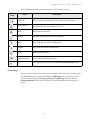
LEDs.........................................................................................................................................................................21
Power LED .....................................................................................................................................................22
XBee LED ......................................................................................................................................................22
Signal strength LED .......................................................................................................................................23
Network LED..................................................................................................................................................24
Button .......................................................................................................................................................................25
Factory reset....................................................................................................................................................26
Enable configuration changes via the device discovery tools ........................................................................26
Enable the device web interface .....................................................................................................................26
Enable a special-purpose Wi-Fi configuration mode .....................................................................................26
Antennas...................................................................................................................................................................27
Regulatory information and certifications................................................................................................................28
RF exposure statement....................................................................................................................................28
FCC certifications and regulatory information (USA only) ...........................................................................28
European Community - CE Mark Declaration of Conformity (DoC)............................................................29
3
Contents
Industry Canada (IC) certifications ................................................................................................................30
Safety statements ............................................................................................................................................31
International EMC (Electromagnetic Emissions/Immunity/Safety) standards...............................................33
Chapter 3: Configuration....................................................................................................................................................... 34
Configuration can be performed programmatically .................................................................................................34
Important configurable settings................................................................................................................................35
Ethernet IP network settings...........................................................................................................................35
Wi-Fi settings..................................................................................................................................................36
Mobile settings and provisioning....................................................................................................................37
NTP time server settings.................................................................................................................................38
iDigi remote device management ...................................................................................................................39
Additional device configuration settings..................................................................................................................40
Python .............................................................................................................................................................40
XBee settings ..................................................................................................................................................40
SureLink™ settings ........................................................................................................................................40
Configuration from the Web interface .....................................................................................................................41
Open the web interface ...................................................................................................................................41
The Home page...............................................................................................................................................44
Configuration settings pages...........................................................................................................................46
Configuration from iDigi Manager Pro....................................................................................................................56
Basic configuration settings............................................................................................................................57
Advanced configuration settings ....................................................................................................................57
XBee Networks page ......................................................................................................................................60
XBee RF module settings ...............................................................................................................................61
SMS settings ...................................................................................................................................................62
Chapter 4: Administration/maintenance.............................................................................................................................. 64
Common administrative tasks .................................................................................................................................64
Firmware updates............................................................................................................................................64
File management.............................................................................................................................................65
Reboot device .................................................................................................................................................65
Administration from the Web interface ...................................................................................................................66
Firmware Update ............................................................................................................................................66
XBee Firmware Update ..................................................................................................................................66
XBee Status ....................................................................................................................................................66
Mobile Status ..................................................................................................................................................67
File Management ............................................................................................................................................74
System Log .....................................................................................................................................................75
Reboot.............................................................................................................................................................76
Administration from iDigi Manager Pro ..................................................................................................................77
4
Contents
Restore Factory Defaults ................................................................................................................................78
Reboot.............................................................................................................................................................78
Disconnect ......................................................................................................................................................78
Firmware.........................................................................................................................................................78
File Management ............................................................................................................................................79
System log ......................................................................................................................................................80
System information.........................................................................................................................................81
Chapter 5: Programming....................................................................................................................................................... 82
Programming resources............................................................................................................................................83
Python .............................................................................................................................................................83
Digi ESP for Python .......................................................................................................................................83
Programming calls through Server Command Interface (SCI) and Remote Command Interface (RCI).......85
Digi Developer Community Wiki ..................................................................................................................85
ConnectPort X2e ZB Wiki..............................................................................................................................85
Digi Python Programmer’s Guide ..................................................................................................................86
Python Support Forum on digi.com................................................................................................................86
Digi-specific Python modules for programming......................................................................................................87
Sample programs......................................................................................................................................................88
Button handling ..............................................................................................................................................88
LED control ....................................................................................................................................................89
Watchdog........................................................................................................................................................90
RCI callback ...................................................................................................................................................91
XBee functions ...............................................................................................................................................93
Sending and receiving SMS messages ...........................................................................................................93
The ConnectPort X2e ZB filesystem .......................................................................................................................94
Differences between Windows and Linux filesystems...................................................................................94
Important directories.......................................................................................................................................94
Access/browse the filesystem from device interfaces ....................................................................................94
Common operations for directories and files..................................................................................................94
The Linux command shell (command-line interface) ..............................................................................................95
Username and password for the Linux command shell..................................................................................95
Connect and log on to the device....................................................................................................................95
Command shell reference documentation ......................................................................................................95
5
About this guide
Introduction
C
H
A
P
T
E
R
1
About this guide
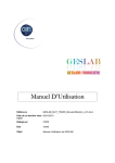
This guide introduces the hardware, firmware, and software features of the ConnectPort® X2e ZB.
It describes how to perform configuration and administrative tasks, and how to develop and run
applications on the device. Programming focuses on basic programming concepts and teaching
through examples. More detailed programming content and program examples are provided in the
Digi ESP™ for Python development environment. It also includes hardware specifications,
certifications, and regulatory information. This guide is intended for a developer/programmer.
Digi contact information
For more information about Digi products, or for customer service and technical support, contact
Digi International.
To Contact Digi International by:
Use:
Mail
Digi International
11001 Bren Road East
Minnetonka, MN 55343
U.S.A.
World Wide Web:
http://www.digi.com/support/
email
Look for the link Contact Digi Support at this
address:
http://www.digi.com/support/
Telephone (U.S.)
(952) 912-3444 or (877) 912-3444
Telephone (other locations)
+1 (952) 912-3444 or (877) 912-3444
6
ConnectPort X2e ZB
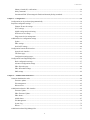
ConnectPort X2e ZB
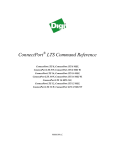
The ConnectPort X2e ZB is a compact, ZigBee®-to-IP gateway that provides low-cost IP
connectivity of RF devices and sensor networks. Featuring an easy development environment, the
ConnectPort X2e enables custom applications to run on the device, with access to XBee® or
ZigBee wireless networks through an XBee RF interface, while providing WAN connectivity to
cloud-based applications through Ethernet, Wi-Fi, or cellular interfaces.
The ConnectPort X2e ZB features an end-to-end development environment, Digi ESP™ for
Python, that allows for rapid M2M-specific application development on the industry standard
Python scripting engine. The Digi ESP for Python environment is an IDE featuring device
detection, debugging, compiling, and downloading of code to Digi gateways.
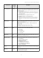
Cellular model
Ethernet and Wi-Fi models
7
Hardware interfaces
Hardware interfaces
ConnectPort X2e ZB hardware interfaces include a button for controlling various device
operations, LEDs that indicate device state and status of connections, link and activity for Ethernet,
Wi-Fi, cellular, and XBee network connections. Some of these hardware features can be controlled
through programming. Hardware interfaces are covered in "Hardware" on page 15.
Configuration and management interfaces
To establish network connectivity with a ConnectPort X2e ZB device, minimal configuration is
required in many environments. This means that you may not need to set or change configuration
settings from their factory defaults to begin developing with the device. As necessary, there are
several user interfaces for interacting with the ConnectPort X2e, for example, to view or change
configuration settings or perform important administrative tasks such as updating firmware or
rebooting the device.
A web-based interface for configuring, monitoring, and administering Digi devices.
iDigi Manager Pro, a remote-management interface.
8
Configuration and management interfaces
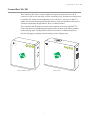
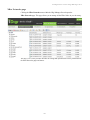
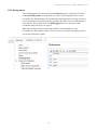
Web interface
The web interface, available via a local network connection to the ConnectPort X2e ZB, provides
an easy way to configure device settings and perform administrative tasks. Device Information
displayed varies by model. Here is the Home page for a ConnectPort X2e Cellular model. Note that
the model name varies according to the Cellular model (UMTS, EVDO Verizon, EVDO Sprint,
etc).
9
Configuration and management interfaces
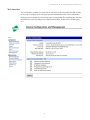
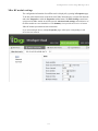
iDigi Manager Pro ™ interface
The default behavior of Connectport X2e ZB is to power up and connect to the
iDigi® Device Cloud™. iDigi Manager Pro is a software-as-a-service, delivering capabilities that
empower IT, network operations and customer support organizations to conquer the challenges of
managing the vast array of equipment in their device networks. As a network grows, the
complexity of effectively managing the network assets grows exponentially. Hosted on the iDigi
Device Cloud, iDigi Manager Pro directly tackles and conquers the universal problems of a
dynamic device network:
Centralized control over large numbers of devices
Reducing service complexity
Maintaining high levels of security
Provisioning and decommissioning of equipment
Adding functionality to device networks
A feature of all Digi gateways, routers, device and components, iDigi Manager Pro provides a
robust suite of network management tools with centralized control via the iDigi Manager Pro
service module.
From the iDigi Manager Pro interface, you can configure devices, remotely update device
firmware, upload and manage Python/iDigi Dia files, remotely reboot devices, reset devices to
factory defaults, backup/restore device configuration properties, import or export the device
configuration properties, track devices, monitor devices and connections.
10
Configuration and management interfaces
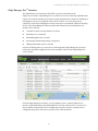
With iDigi Manager Pro, management of large populations of devices is made easy. Devices can be
tagged and grouped together enabling management tasks to groups of devices within a network
simultaneously. Furthermore, the Scheduled Operations feature allows device management tasks to
be automated and scheduled to run either on a one-time or a recurring basis, against a single device
or multiple devices. The Alarms capability of iDigi Manager Pro facilitates monitoring the health
of a device network. For instance, should a device disconnect or stay connected for longer than a
specified period, an alarm fires and notification of the alarm can be sent via email in real-time.
In addition, the iDigi Web Services provide seamless integration from Digi gateways into customer
back office applications. These iDigi Web Services are accessed on the Help and API Explorer
tab of the iDigi interface.
Some things to note about using iDigi Manager Pro:
Devices must be registered on iDigi Manager Pro before they can be accessed via the
iDigi platform.
To minimize network traffic, iDigi Manager Pro uses caching. As a result, device
settings can be out-of-sync between the device and the settings viewed on the iDigi
Manager Pro console.
Device information can be refreshed on demand when the device is connected, and is
refreshed automatically when a device connects.
For more information on iDigi Manager Pro as a remote device network management solution, see
these resources:
iDigi User’s Guide
iDigi Web Services Programming Guide
iDigi tutorials and other documents available on www.iDigi.com
11
Programming interfaces and capabilities
Programming interfaces and capabilities
The ConnectPort X2e ZB allows custom embedded logic via the Python scripting language. To
meet the needs of customers with varying levels of Python expertise and application complexity, a
number of development strategies are supported, which can be mixed and matched as a developer
sees fit:
Python development independent of the target device
The ConnectPort X2e ZB features a standard Python 2.7 distribution, allowing applications that are
not dependent on Digi-proprietary interface modules to be developed and tested independently of
the device. Scripts developed in this manner can generally be transferred to the device for final
testing at the end of the development cycle, with a PC serving as a device proxy during the bulk of
development.
Python development on the target device
The ConnectPort X2e ZB features a Linux shell interface allowing a developer to experiment with
the Python interpreter interactively, create scripts, launch scripts, and control their operation.
Digi ESP for Python
The ConnectPort X2e ZB is supported by the Digi ESP for Python, an IDE featuring device
detection, debugging, compiling and downloading of iDigi Dia/Python code to Digi gateways.
Integrated into the Digi ESP are example applications that can demonstrate the use of some of
Digi’s proprietary Python extensions, serving as templates for applications seeking to incorporate
common functionality.
iDigi Dia
The ConnectPort X2e ZB is supported by the iDigi Dia application framework, which is provided
within Digi ESP for Python. The iDigi Device Integration Application (“Dia”) is an application
software platform for Digi gateways. iDigi Dia makes connecting remote devices and sensors to
Digi gateway products easy by providing a ready-to-use software. Put simply, the iDigi Dia
framework is used to gather data from XBee sensor networks, transform the data into a useful form,
and push the data to the iDigi Device Cloud for consumption by a user. iDigi Dia is written in the
Python programming language, and can be extended to meet unique device connectivity
requirements. Particularly valuable in conjunction with the Digi ESP for Python, the iDigi Dia
framework seeks to shrink the development cycle for complex data gathering and transformation
applications. With abstractions for components like interface handling (drivers), data management
(channels), data delivery (presentations); and a library of ready-to-use modules for common
operations; the iDigi Dia framework allows a developer to focus efforts on proprietary logic, not
the glue that holds an application together. The iDigi Dia application framework also provides the
shortest path to integration on proprietary logic with Digi’s network device and data management
platform, iDigi.
12
Product differences from predecessor ConnectPort X products
Linux command shell
Note: The ConnectPort X2e ZB also has a Linux shell command-line interface. While Digi ESP for
Python is intended as the main programming interface, this interface may be used for some
programming and device management tasks. This interface is accessed with
a username of python and password dbps, and is described in "The Linux command shell
(command-line interface)" on page 95.
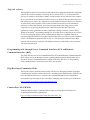
Product differences from predecessor ConnectPort X products
ConnectPort X2e ZB gateways differ from predecessor ConnectPort X products. These differences
are of importance to programmers and integrators who are familiar with the predecessor devices
and need to develop applications and install or manage the gateway. This list of differences
assumes that the reader has knowledge of the features and functions of predecessor ConnectPort X
products.
Operating system: The ConnectPort X2e ZB is built on the industry-standard Linux
operating system, versus a Digi-proprietary embedded operating system.
Memory: The ConnectPort X2e ZB has 64MB of RAM and 128MB of Flash memory.
Users have access to up to 20MB of RAM and up to 20MB of Flash memory.
Predecessor devices had less RAM and Flash available for custom Python applications.
System date and time: The ConnectPort X2e ZB, for reasons of improved security, has
a greater dependence on time synchronization than predecessor products. In so doing,
the ConnectPort X2e ZB expects to use the standard Network Time Protocol (NTP),
requiring connectivity with an external NTP time server. Without a proper sense of
time, the device will be unable to correctly validate security certificates, disabling the
ability to connect to iDigi, as well as disabling the ability to update the firmware.
Button: The ConnectPort X2e ZB features a programmable button. The button can be
configured to activate some Digi native features (such as returning a device to its factory
defaults), and can also be used by custom applications. For more information on the
button see page 25. This button behavior differs from the Reset button behavior on the
ConnectPort X2.
LED behaviors and meanings: The ConnectPort X2e ZB has some differences in LED
behavior and meaning from predecessor ConnectPort X products. See page 21 for
descriptions and page 89 for programming example.
13
Where to find more information
User interfaces:
–
The ConnectPort X2e ZB has a web user interface for both network configuration and
access to the log file for troubleshooting the initial connection to iDigi. For more
information on the web interface, see "Configuration" on page 34.
–
Command-line interface differences: The ConnectPort X2e ZB allows access to the
Linux shell using SSH. This shell and common operations are described on page 95.
Access to the gateway is at the user level; the user is named python and the password is
dbps. Access to a command-line interface through Telnet is not supported for network
security reasons. Commands in the command-line interface for predecessor
ConnectPort X products are not supported. However, some ConnectPort X2 commandline interface commands have equivalents in the Remote Command Interface (RCI).
Firmware updates: Due to the complexity of the Linux-based system, standard
firmware updates cannot be used to downgrade a system.
Logging: The ConnectPort X2e ZB supports continuous logging for troubleshooting.
The log files can be browsed from the web interface or pulled from the device filesystem
in the iDigi interface. They are stored in the Linux filesystem in the /WEB/logging
directory and persist across reboots and power cycles.
Supported Python version: The ConnectPort X2e ZB uses Python interpreter version
2.7. Many predecessor ConnectPort X products use Python 2.4.
Any custom-compiled Python code must be recompiled for Python interpreter 2.7.
Custom Python modules are not 100% compatible with the ConnectPort X2e ZB.
Therefore, porting may be required in addition to recompiling.
Where to find more information
In addition to this guide, find additional product and feature information in the these documents.
These documents are available from Digi’s Support page http://www.digi.com/support/ unless
otherwise noted.
ConnectPort® X2e ZB Getting Started Guide
XBee/XBee-PRO ZB SMT RF Modules Product Manual (90000976), for more
information about features and operation of the XBee RF module mounted inside the
gateway
ConnectPort X2e ZB programming content within Digi ESP for Python
The Wiki page for additional programming content for ConnectPort X2e products:
http://www.digi.com/wiki/developer/index.php/ConnectPort_X2e
The Programming section lists several references and tutorials for users new to a Linuxbased filesystem and the ash command shell.iDigi Dia library documentation
iDigi User’s Guide
iDigi Web Services Programming Guide
iDigi tutorials and other documents available on iDigi.com
14
Hardware
C
H
A
P
T
E
R
2
This section provides hardware specifications, reviews key hardware features, and lists regulatory
statements and certifications of the ConnectPort X2e ZB.
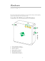
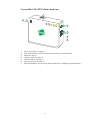
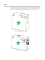
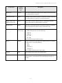
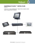
ConnectPort X2e ZB Ethernet and Wi-Fi hardware
2
3
1
4
5
6
7
1
2
3
4
5
6
7
Power requirements. See page 17.
LED status indicators. See page 21.
Button. See page 25.
Ethernet features. See page 17.
Wi-Fi features. See page 18.
XBee RF module. See page 18.
Antennas (internal). See page 27.
15
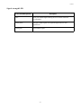
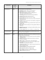
ConnectPort X2e ZB Cellular hardware
7
3
2
1
4
5
6
1
2
3
4
5
6
7
Power requirements. See page 19.
LED status indicators. See the Getting Started Guide topic “Troubleshooting.”
Button. See page 25.
Cellular features. See page 20.
XBee RF module. See page 18.
Antennas (internal). See page 27.
SIM card installation. See the Getting Started Guide topic “Configuring for GSM Networks.”
16
Hardware specifications
Hardware specifications
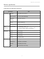
ConnectPort X2e ZB Ethernet and Wi-Fi
Specification
Environmental
Power
requirements
Value
Operating
temperature
32° F to 104° F (0° C to 40° C)
Relative humidity
5% to 95% (non-condensing)
Storage and
transport
temperature
-40 to 185F (-40 to 85C)
Altitude
6560 feet (2000 meters)
Ethernet isolation
500 VAC min per IEEE802.3/ANSI X3.263
DC power input
Voltage
Dimensions
Ethernet
input: 5 VDC +/- 5%
Power consumption: Typical: 1.2 W, Max: 2.5 W
Connector: 2.35mm x 5.7mm, center pin positive.
Length
3 in (7.62 cm)
Width
3 in (7.62 cm)
Depth
1 in (2.54 cm)
Weight
0.15 lb (0.07 kg)
Ethernet Ports
1 RJ-45 port
Physical Layer
10/100 Base-T (Auto-MDIX)
Data Rate
10/100 Mbps (auto-sensing)
Mode
Full or half duplex (auto-sensing)
17
Hardware specifications
Specification
Value
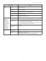
802.11
b/g/n (2.4GHz only)
Data Rate
Up to 72.2 Mbps
Transmit Power
18 dBm typical (varies by mode and channel)
Receiver Sensitivity
-87 dBm @ 11 Mbps
Modes
Infrastructure Client mode only
XBee
See the
XBee/XBeePRO ZB SMT
RF Modules
Product Manual
(90000976) for
complete
specifications
and product
information.
Module type
XBee® ZB SMT
Transmit power
The
Receiver sensitivity
(1% PER)
-102 dBm
Development
Python version
2.7.1
Memory
64 MB RAM, 128 MB Flash
20 MB RAM 20 MB Flash available for Python applications
Wi-Fi
Domestic product version uses the XBee-PRO RF module, with
a transmit power of 63mW (+18dBm).
The International product version uses the regular XBee RF module,
with a transmit power of 6.3 mW (+8 dBm).
18
Hardware specifications
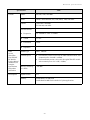
ConnectPort X2e ZB Cellular
Specification
Environmental
Power
requirements
Value
Operating
temperature
32° F to 104° F (0° C to 40° C)
Relative humidity
5% to 95% (non-condensing)
Storage and
transport
temperature
-40 to 185F (-40 to 85C)
Altitude
6560 feet (2000 meters)
Ethernet isolation
500 VAC min per IEEE802.3/ANSI X3.263
DC power input
Voltage
Dimensions
Ethernet
input: 5 VDC +/- 5%
Power consumption: Typical: Typical: 3.5W, Max: 15W
Connector: 2.5mm x 5.7mm, center pin positive.
Length
4 in (10.16 cm)
Width
3 in (7.62 cm)
Depth
1 in (2.54 cm)
Weight
0.37 lb (0.082 kg)
Ethernet Ports
1 RJ-45 port
Physical Layer
10/100 Base-T (Auto-MDIX)
Data Rate
10/100 Mbps (auto-sensing)
Mode
Full or half duplex (auto-sensing)
19
Hardware specifications
Specification
Cellular
Value
EDGE
850, 900, 1800, 1900 MHz
GSM
UMTS / HSPA 800/850, 900, 1700 (AWS), 1900, 2100 MHz
CDMA
1xRTT 800, 1900 MHz
EV-DO 800, 1900 MHz
Internal Antenna:
Frequencies
24 – 960MHz to 1700 – 2170MHz
VSWR
3:1 max
Polarization
Linear
Impedance
50 Ohm
XBee
See the
XBee/XBeePRO ZB SMT
RF Modules
Product Manual
(90000976) for
complete
specifications
and product
information.
Module type
XBee® ZB SMT
Transmit power
The
Receiver sensitivity
(1% PER)
-102 dBm
Development
Python version
2.7.1
Memory
64 MB RAM, 128 MB Flash
20 MB RAM 20 MB Flash available for Python applications
Domestic product version uses the XBee-PRO RF module, with
a transmit power of 63mW (+18dBm).
The International product version uses the regular XBee RF module,
with a transmit power of 6.3 mW (+8 dBm).
20
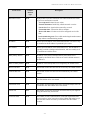
LEDs
LEDs
The ConnectPort X2e ZB has several LEDs. All LEDs have default behaviors, described in this
section. LED descriptions are in the “Troubleshooting” section of the Getting Started Guide. Some
LEDs can also be controlled programmatically, as discussed in "LED control" on page 89.
Power
XBee
Network
Ethernet and Wi-Fi models
Power
XBee
Signal
Strength
Network
Cellular model
21
LEDs
Power LED
Color and blink pattern
Description
Off
No power.
Solid green
Device is powered. This state does not indicate that the device is fully
operational. The Network LED and its states convey such information.
Blinking green
(Cellular model only)
Device is updating firmware. Do not unplug unit.
XBee LED
The XBee LED indicates the status of the connection of the XBee RF module in the ConnectPort
X2e ZB to an XBee wireless network. The behavior of the XBee LED varies depending on whether
the ConnectPort X2e ZB acts as a coordinator or a router. For information on changing the
ConnectPort X2e ZB from a coordinator to a router, see the XBee/XBee-PRO ZB SMT RF Modules
Product Manual.
ConnectPort X2e ZB as Coordinator
Color and blink pattern
Description
Solid green
The XBee RF module has not started a network.
Blinking green
The XBee RF module has started a network.
ConnectPort X2e ZB as Router
Color and blink pattern
Description
Solid green
The XBee RF module has not joined a network.
Blinking green
The XBee RF module has joined a network.
22
LEDs
Signal strength LED
Color and blink pattern
Description
OFF
No or poor cellular signal. Moving device to a better location is
recommended.
Solid yellow
Adequate cellular signal. This signal strength works for most
applications.
Solid green
Good cellular signal.
23
LEDs
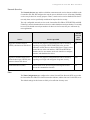
Network LED
The Network LED indicates the status of the connection of the ConnectPort X2e ZB to both a
communications network and an iDigi server. The LED can be user-controlled; see page 89 for
details.
Color and
blink
pattern
Ethernet
Wi-Fi
Cellular
Off
No Ethernet detected.
No Wi-Fi AP or Ad-Hoc
networks detected.
No cellular network
detected.
Blinking
yellow
(slow)
Ethernet interface identified;
waiting for link.
Wi-Fi AP or Ad-Hoc
network detected.
Connecting to Wi-Fi.
Waiting for association.
Cellular network(s) detected.
Registering on cellular
network.
Blinking
yellow (fast)
Connected to Ethernet.
Establishing LAN
connection. Waiting for IP
address.
Connected to Wi-Fi.
Establishing LAN
connection. Waiting for IP
address.
Registered on cellular
network. Establishing WAN
connection. Waiting for IP
address.
Solid yellow
An IP address has been
assigned to the gateway.
Connected to LAN. Waiting
for iDigi service to take
control, and for DNS
resolution of server chosen
by the iDigi service.
An IP address has been
assigned to the gateway.
Connected to LAN. Waiting
for iDigi service to take
control, and for DNS
resolution of server chosen
by the iDigi service.
An IP address has been
assigned to the gateway.
Connected to WAN. Waiting
for iDigi service to take
control, and for DNS
resolution of server chosen
by the iDigi service.
Alternating
between
yellow and
green
The gateway cannot connect to iDigi. The two most common reasons for this state are:
The gateway cannot connect to a DNS server to resolve the iDigi server address. See page 91.
The gateway cannot connect to an NTP time server to get the correct time. See page 91.
Blinking
green (slow)
Verifying Internet connection. Waiting for network connection to the chosen server.
Blinking
green (fast)
Connected to Internet. Establishing iDigi connection. Waiting for protocol level “connection”
with iDigi server, which might include authentication.
Solid green
Gateway is connected to the iDigi server.
24
Button
Button
The button on the ConnectPort X2e ZB is capable of performing a number of Digi-defined actions,
including:
Reset the device configuration settings to their factory defaults
Enable configuration changes via the device discovery tools within a five-minute
window
Enable the device web interface
Enable a special purpose Wi-Fi configuration mode
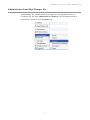
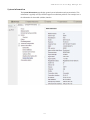
Some of these features are enabled on the button by default, but all behaviors can assigned either to
the “default” button, or to “none” (to disable the feature); see below for detailed descriptions of
these features. This assignment is done through the iDigi Manager Pro interface, in
Properties > Advanced Configuration > Button Service Assignment. The choices for each
button service assignment are “Default button,” “per Digi product specification,” which means
to use the default behaviors described on the following page, and “Feature disabled,” which
means that the feature is not assigned to the button.
The button state can also be read by a Python application. This can be done in conjunction with the
Digi standard actions, the button behaviors can be enabled/disabled individually, or all Digi
behaviors can be disabled to provide full responsibility for the button to an application. See "Button
handling" on page 88 for details.
Button
Button
25
Button
Factory reset
Pressing the button for over 10 seconds after the ConnectPort X2e ZB is running resets the device
to its factory default configuration. This action clears any configuration settings you may have
entered through the supported device interfaces. This feature is assigned to the button by default.
Enable configuration changes via the device discovery tools
The default behavior for the ConnectPort X2e ZB is that it can be discovered through Digi Device
Discovery and configuration settings can be displayed and changed, with no time-limit window;
therefore, the button behavior is disabled. This feature, when enabled, restricts device state changes
via the device discovery tools to a five-minute window since the most-recent button press.
Note: When an attempt is made to change configuration settings using the Digi Device Discovery
tool, a password prompt will be displayed. Leave the field in the prompt blank and click OK.
Enable the device web interface
The default behavior for the ConnectPort X2e ZB is that the feature of controlling whether the web
interface is exposed is disabled. That is, the web interface is always available and no button press is
needed to access the web interface. When this feature is assigned to the button, and web interface
availability is restricted, a user needs to press the button to access the web interface. The web
interface will be open for a five minute window since the most recent button press.
Enable a special-purpose Wi-Fi configuration mode
When assigned to the button, the feature of enabling a special-purpose Wi-Fi configuration mode
allows a button press to create a temporary access point for configuration of the device if the device
has not yet already been configured for Wi-Fi. Each button press extends the window of access
point mode operation to five minutes from the time of the button press. If the feature is not
assigned to the button, no Wi-Fi configuration access point mode is available. The default
behavior on the ZB is the feature is assigned to the button.
When the special-purpose Wi-Fi configuration mode is enabled, enable Access Point mode on your
device by pressing the button. Configure the Wi-Fi interface of your laptop to connect to the
ConnectPort X2e ZB gateway’s access point. The name (SSID) of the access point will be
cpx2e-zb-xxxxxxxxxx, where xxxxxxxxxx is the serial number of the gateway.
26
Antennas
Antennas
The ConnectPort X2e ZB has internal antennas.
All models have an internal antenna for the XBee RF module.
Wi-Fi models have an additional internal antenna.
Cellular models have an additional internal cellular antenna. For these models, if the
Signal Strength LED is off, try moving the device to another location to improve signal
strength. Placement can drastically increase the signal strength of a cellular connection.
Often times, just moving the router closer to an exterior window or to another location
within the facility can result in optimum reception. Another way of increasing
throughput is by physically placing the device on the roof of the building, in an
environmentally safe enclosure with proper moisture and lightning protection.
27
Regulatory information and certifications
Regulatory information and certifications
RF exposure statement
In order to comply with RF exposure limits established in the ANSI C95.1 standards, the distance
between the antenna or antennas and the user should not be less than 20 cm.
FCC certifications and regulatory information (USA only)
FCC Part 15 Class B
Radio Frequency Interface (RFI) (FCC 15.105)
This device has been tested and found to comply with the limits for Class B digital devices
pursuant to Part 15 Subpart B, of the FCC rules. These limits are designed to provide reasonable
protection against harmful interference in a residential environment. This equipment generates,
uses, and can radiate radio frequency energy, and if not installed and used in accordance with the
instruction manual, may cause harmful interference to radio communications. However, there is no
guarantee that interference will not occur in a particular installation. If this equipment does cause
harmful interference to radio or television reception, which can be determined by turning the
equipment off and on, the user is encouraged to try and correct the interference by one or more of
the following measures:
Reorient or relocate the receiving antenna.
Increase the separation between the equipment and receiver.
Connect the equipment into an outlet on a circuit different from that to which the
receiver is connected.
Consult the dealer or an experienced radio/TV technician for help.
Labeling Requirements (FCC 15.19)
This device complies with Part 15 of FCC rules. Operation is subject to the following two
conditions: (1) this device may not cause harmful interference, and (2) this device must accept any
interference received, including interference that may cause undesired operation.
If the FCC ID is not visible when installed inside another device, then the outside of the device into
which the module is installed must also display a label referring to the enclosed module FCC ID.
Modifications (FCC 15.21)
Changes or modifications to this equipment not expressly approved by Digi may void the user’s
authority to operate this equipment.
28
Regulatory information and certifications
European Community - CE Mark Declaration of Conformity (DoC)
We:
Manufacturer’s Name:
Digi International
of:
Corporate Headquarters:
11001 Bren Road East
Minnetonka MN 55343
Manufacturing Headquarters: 10000 West 76th Street
Eden Prairie MN 55344
Declare under our sole responsibility that the product:
Product Name
Model Number
ConnectPort X2e ZB
50X2E-Z3C-XXX-XX
to which this declaration relates are in conformity with the essential requirements and other
relevant requirements of Directive 1999/5/EC (R&TTE):
Safety (article 3.1a)
–
EN 60950-1:2006
EMC (article 3.1b)
–
EN 55022:2010 Class B
–
EN 55024:2010
–
EN 61000-3-2:2006
–
EN 61000-3-3:2008
–
EN 301 489-17 V2.1.1:2009 Class B
–
EN 301 489-7 V1.3.1
–
EN 301 489-24 V1.5.1
Spectrum (article 3.2)
–
EN 300 328 V1.7.1:2006
–
EN 301 511 V9.02
–
EN 301 908-1 V4.2.1
–
EN 301 908-2 V4.2.1
29
Regulatory information and certifications
Industry Canada (IC) certifications
This digital apparatus does not exceed the Class B limits for radio noise emissions from digital
apparatus set out in the Radio Interference Regulations of the Canadian Department of
Communications.
Le present appareil numerique n’emet pas de bruits radioelectriques depassant les limites
applicables aux appareils numeriques de la class B prescrites dans le Reglement sur le brouillage
radioelectrique edicte par le ministere des Communications du Canada.
30
Regulatory information and certifications
Safety statements
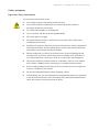
Important Safety Information
To avoid contact with electrical current:
Never install electrical wiring during an electrical storm.
Never install an Ethernet connection in wet locations unless that connector is
specifically designed for wet locations.
Use caution when installing or modifying lines.
Use a screwdriver and other tools with insulated handles.
Wear safety glasses or goggles.
Do not place Ethernet wiring or connections in any conduit, outlet or junction box
containing electrical wiring.
Installation of inside wire may bring you close to electrical wire, conduit, terminals and
other electrical facilities. Extreme caution must be used to avoid electrical shock from
such facilities. Avoid contact with all such facilities.
Ethernet wiring must be at least 6 feet from bare power wiring or lightning rods and
associated wires, and at least 6 inches from other wire (antenna wires, doorbell wires,
wires from transformers to neon signs), steam or hot water pipes, and heating ducts.
Do not place an Ethernet connection where it would allow a person to use an Ethernet
device while in a bathtub, shower, swimming pool, or similar hazardous location.
Protectors and grounding wire placed by the service provider must not be connected to,
removed, or modified by the customer.
Do not touch uninsulated Ethernet wiring if lightning is likely!
External Wiring: Any external communications wiring installed needs to be constructed
to all relevant electrical codes. In the United States this is the National Electrical Code
Article 800. Contact a licensed electrician for details.
31
Regulatory information and certifications
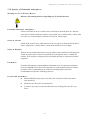
5.10 Ignition of Flammable Atmospheres
Warnings for Use of Wireless Devices
Observe all warning notices regarding use of wireless devices.
((( )))
Potentially Hazardous Atmospheres
Observe restrictions on the use of radio devices in fuel depots, chemical plants, etc. and areas
where the air contains chemicals or particles, such as grain, dust, or metal powders, and any other
area where you would normally be advised to turn off your vehicle engine.
Safety in Aircraft
Switch off the wireless device when instructed to do so by airport or airline staff. If the device
offers a ‘flight mode’ or similar feature, consult airline staff about its use in flight.
Safety in Hospitals
Wireless devices transmit radio frequency energy and may affect medical electrical equipment.
Switch off wireless devices wherever requested to do so in hospitals, clinics, or health care
facilities. These requests are designed to prevent possible interference with sensitive medical
equipment.
Pacemakers
Pacemaker manufacturers recommended that a minimum of 15cm (6 inches) be maintained
between a handheld wireless device and a pacemaker to avoid potential interference with the
pacemaker. These recommendations are consistent with independent research and
recommendations by Wireless Technology Research.
Persons with Pacemakers:
Should ALWAYS keep the device more than 15cm (6 inches) from their pacemaker
when turned ON.
Should not carry the device in a breast pocket.
If you have any reason to suspect that the interference is taking place, turn OFF your
device.
32
Regulatory information and certifications
International EMC (Electromagnetic Emissions/Immunity/Safety) standards
This product complies with the requirements of following Electromagnetic Emissions/Immunity/
Safety standards.
There are no user-serviceable parts inside the product. Contact your Digi representative through
"Digi contact information" on page 8 for repair information.
Emissions
AS/NZS 4268:2008 (Amended by
A1:2010) Class B (Wi-Fi only)
AS/NZS CISPR 22:2009 Class B
EN 301 489-17 V2.1.1:2009 Class
B (Wi-Fi only)
EN 55022:2010 Class B
EN 61000-3-2:2006
EN 61000-3-3:2008
FCC Part 15 Subpart B Class B
FCC Part 15 Subpart C (Wi-Fi
only)
ICES-003:2004 Class B
RSS-Gen:2010 (Wi-Fi only)
RSS-210:2010 (Wi-Fi only)
Immunity
EN 301 489-17 V2.1.1:2009
(Wi-Fi only)
EN 55024:2010
EN 301 489-24 V1.5.1 (Cellular
only)
33
Safety
IEC 60950-1:2005
EN 60950-1:2006
UL 60950-1
CSA C22.2 No. 60950-1
Configuration can be performed programmatically
Configuration
C
H
A
P
T
E
R
3
While the ConnectPort X2e ZB is designed to allow network communication with minimal
configuration, there are several configuration settings that can be adjusted. This section covers
those configuration settings and configuration of these settings from the web interface, and from
iDigi Manager Pro.
Configuration can be performed programmatically
In addition to the methods described in this chapter, configuration can be performed
programmatically, through iDigi Web Services, and natively using Python modules. See page 85.
34
Important configurable settings
Important configurable settings
For the ConnectPort X2e ZB, most settings have reasonable defaults that do not need to be
changed. However, these are some important settings available in the configuration interfaces that
get the device up and communicating.
Ethernet IP network settings
Wi-Fi settings
Mobile settings
NTP time server settings
iDigi remote device management
Ethernet IP network settings
Ethernet IP network settings configure how the IP address of the Digi device for Ethernet network
communications is obtained, either by DHCP or by using a static IP address, subnet mask, and
default gateway, and Domain Name System (DNS) servers.
DHCP
The ConnectPort X2e ZB uses a DHCP server to obtain its IP address information, by default. A
DHCP server needs to provide an IP address, subnet mask, default gateway, and Domain Name
System (DNS) server for the device. If you disable DHCP, you must set all of these settings
yourself.
In the absence of a DHCP server, a static IP address will need to be assigned, most easily by
accessing the device Digi Device Discovery tool and changing the network settings through that
interface.
IP Address
Subnet Mask
Default Gateway
These settings should be considered as a group, and only come into play when automatic IP address
assignment is disabled.
IP Address: The IP address is a 4-part ID assigned to network devices. IP addresses are
in the form of 192.168.2.2, where each number is between 0 and 255.
Subnet Mask: The Subnet Mask is combined with the IP address to determine which
network this Digi device is part of. A common subnet mask is 255.255.255.0.
Default Gateway: The IP address of the computer that enables this Digi device to
access other networks, such as the Internet.
35
Important configurable settings
DNS servers
A DNS (Domain Name System) server is an Internet service that resolves domain names into IP
addresses. Name resolution is important when connecting to iDigi, as the Digi servers are provided
as fully-qualified domain names.
ConnectPort X2e ZB is capable of using up to three DNS servers. Up to two of these slots may be
filled with DNS servers from dynamic IP assignment sources, leaving at least one slot always
available for static DNS server configuration. A reasonable default is supplied for one static DNS
server, but this default may not be appropriate for all customer networks.
Wi-Fi settings
If the ConnectPort X2e ZB will use Wi-Fi communications, several Wi-Fi settings are important to
enable network connectivity.
A Wi-Fi configuration wizard is used to configure the Wi-Fi interface. This wizard
“teaches” a Wi-Fi ConnectPort X2e ZB device the wireless parameters needed to further
configure wireless settings and operation.
SSID: This value should be set to the name of your wireless access point. The wizard
will display a list of access point names (SSIDs) select the name of your access point.
Network security: The type of network security used on the wireless network will need
to be specified. Select your network security from the list provided.
36
Important configurable settings
Mobile settings and provisioning
The mobile settings configure how to connect to mobile (cellular) networks using the mobile
connection, including the service provider, service plan, and settings used in connecting to the
mobile network.
The process for provisioning your device and the settings displayed on the Mobile Configuration
page vary according to whether the mobile service provider network used with your Digi Cellular
Family product is based on GSM (Global System for Mobile communication) or CDMA (CodeDivision Multiple Access). If your device has not already been provisioned, see the Getting Started
Guide.
SMS settings
An additional set of mobile settings configure the use of Short Message Service (SMS)
communications for the ConnectPort X2e ZB. The SMS settings allow you to send messages and
commands to and from the ConnectPort X2e ZB in the form of SMS messages. There are two types
of SMS interactions supported: iDigi SMS and Raw SMS messaging.
iDigi SMS
The iDigi SMS feature supports sending and receiving SMS messages between iDigi and an
iDigi-registered device. iDigi SMS can be used to:
Send an SMS message to the iDigi device in order to have the iDigi device dynamically
establish its EDP connection with iDigi
Send user defined data to and from iDigi and iDigi devices
Perform limited device management such as pinging the iDigi device, as well as
provisioning it properly for SMS functionality with iDigi
With iDigi devices that support the iDigi SMS feature, iDigi can send an SMS message to the
iDigi device instructing the device to establish its EDP connection to iDigi. Once the iDigi
device has uploaded its data to iDigi, iDigi can then disconnect the EDP connection resulting
in lower cellular data usage since the EDP connection no longer needs to be maintained around
the clock.
iDigi SMS support makes sending data between iDigi devices and iDigi easy and reliable. This
iDigi feature augments and overcomes the limitations of using basic SMS messages in several
ways:
Send request/response pairs allowing confirmation of messages, as well as allowing
iDigi devices to respond to user commands sent though iDigi
Send messages larger than a single SMS message. iDigi will automatically split up and
re-assemble large messages into a multi-part message without requiring any user
intervention.
Send binary messages (basic SMS messages are limited to text only)
Guarantee data integrity (basic SMS messages do not guarantee integrity)
Complete details on configuring and using iDigi SMS are in the iDigi User’s Guide.
37
Important configurable settings
Raw SMS messaging
In addition to iDigi-formatted messages, a user can send an SMS message without iDigi modifying
it any way. This method is referred to as “raw SMS messaging”. This type of messaging is useful in
cases when customers wish to use every byte of the SMS message (the iDigi protocol takes
approximately 5 bytes per message of overhead), or when using a device that doesn't have iDigi
protocol support but does have SMS support.
Raw messages are not modified by iDigi and are subject to the restrictions of the SMS messaging
interface. SMS raw messages are subject to the limitations of standard SMS messages: They can be
a maximum of 160 characters. The supported characters are dependent on your carrier, but are
character only (not binary). They are not guaranteed to be delivered, may be delivered more than
once, and are not guaranteed to be correct (they are subject to corruption).
To learn more about this feature, see the iDigi Web Services Programming Guide.
Note: using SMS can involve additional costs
SMS is a feature that may be available as part of your mobile service agreement. However, sending
and receiving short messages (or “text messages”) may have additional costs. Before using the
SMS capabilities of your Digi device, verify with your mobile service provider that your agreement
includes SMS as part of your service plan. Understand the costs of SMS before you enable the
SMS features on this Digi device.
NTP time server settings
The ConnectPort X2e ZB uses Network Time Protocol (NTP) for time synchronization. Using NTP
requires an external NTP time server. Time synchronization is critical to the security of the device,
including validating the certificates that sign firmware update images, as well as to verify the
server certificate if/when connecting to iDigi. Steps are taken to preserve a sense of the time across
reboots, but the availability of an NTP server or servers is important to the long-term health of the
device.
The NTP servers are configured in the web interface on the Configuration > Time page. In
environments where the device cannot directly connect to the Internet, configuration changes to
point to a local NTP server are important. Many users will not need to change the time server
setting. If already connected to iDigi, it is also possible to adjust the time server configuration.
The default values for the NTP time server settings are as follows:
NTP server 1: my.idigi.com
NTP server 2: 0.idigi.pool.ntp.org
NTP server 3: 1.idigi.pool.ntp.org
NTP server 4: 2.idigi.pool.ntp.org
TimeZone: Coordinated Universal Time (UTC)
38
Important configurable settings
iDigi remote device management
The ConnectPort X2e ZB, as with many of its predecessors, is compatible with the iDigi device and
data management platform. iDigi provides a mechanism to do more advanced device configuration
than is generally possible in the web interface Once the device has established network
connectivity to the iDigi server, it will be manageable remotely using the iDigi interface.
Configurable iDigi settings include:
iDigi Connectivity: Enabled by default. You may wish to disable this feature if you
have no use for iDigi, and wish to eliminate any iDigi-related network traffic.
iDigi Server Name: The value for this setting is generally a Fully Qualified Domain
Name (FQDN) pointing to one of the Digi iDigi servers. This setting is configurable
through the web interface, in the Configuration > iDigi Connectivity page, and through
iDigi, in the Advanced configuration settings. The default value is my.idigi.com
iDigi Server Port: This setting is configurable on the iDigi Configuration page, not
through iDigi Manager Pro. The default value is 3199
Proxy Server Name / Port: A path to an iDigi server can be made through a local
HTTP proxy, such as squid. provided that server is used to simply remap the target IP
address and port number, without extra authentication or other security measures.
39
Additional device configuration settings
Additional device configuration settings
There are several additional device features that are not essential for IP network connectivity, but
which will require configuration settings to be entered or changed from their defaults.
Python
Any Python programs loaded onto the ConnectPort X2e ZB can be configured to start
automatically at system startup.
XBee settings
The ConnectPort X2e ZB provides a gateway between an Internet Protocol (IP) network wired or
wireless devices and a network of various wireless devices containing XBee or ZigBee wireless RF
modules. Typically, these wireless devices are small sensors and controllers. Remote nodes in an
XBee network can be other Digi ZB or SE nodes, or 3rd-party nodes.
The XBee module can be configured as a coordinator or router in an XBee or ZigBee network. For
information on configuring the XBee module as a coordinator or router, and for complete XBee
module settings and their descriptions, and discussions of XBee network concepts, see the
XBee/XBee-PRO ZB SMT RF Modules Product Manual (90000976).
SureLink™ settings
Digi SureLink™ is an optional feature that monitors the integrity of an established network
connection. Several settings and tests can be configured to perform a selected test to examine the
functional integrity of the network connection, and take action to recover the connection in the
event that it is lost.
Currently SureLink is supported for cellular communications only. The SureLink feature and its
settings are off by default, and must be enabled and configured. To configure SureLink from the
web interface, see page 49. To configure SureLink from iDigi, see page 58.
40
Configuration from the Web interface
Configuration from the Web interface
The web interface for ConnectPort X2e ZB is intended to support basic feature configuration as
well as critical network configuration. Not every device setting is displayed in this interface. For
more extensive access to settings, use the iDigi Manager Pro interface.
Open the web interface
To open the web interface, use the Digi Device Discovery utility in Digi ESP for Python to get the
IP address for the device. The Digi Device Discovery utility locates Digi devices on a network. It
uses a Digi International-proprietary protocol, Advanced Digi Discovery Protocol (ADDP), to
discover the Digi devices on a network, and displays the discovered devices in a list. Digi Device
Discovery can be launched from the Digi ESP for Python interface.
Note: If you already know the IP address for the device, you can open a web browser and enter the
IP address in the address bar to open the web interface. For example http://10.101.1.178
Launch Digi Device Discovery
To launch Digi Device Discovery within Digi ESP:
1
Launch Digi ESP from the Start menu: Start > Digi > Python > Dev Tools... > Digi ESP for
Python.
2
Open the Device Manager: from the Digi ESP main menu, selecting
Device Options > Device Manager, or on the toolbar, click the Device Manager button.
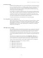
3
In the Device Manager window, click on the Device Discovery button located on the toolbar
above the list of available remove devices.
41
Configuration from the Web interface
4
A dialog is displayed for asking where to look for connected devices. Make sure the option
Local Area Network is selected and click OK.
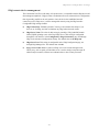
5
The Digi Device Discovery dialog is displayed, listing the devices found. The IP Address
column displays the IP address of every device. Locate the device in the list of devices.
42
Configuration from the Web interface
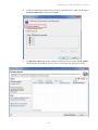
6
Open an internal browser within Digi ESP by choosing Window > Show View > Other >
Internal Web Browser. Click OK.
7
In the browser, enter the IP address of your device, in the address bar of the browser:
http://device_ip_address
For example:
http://10.101.1.178
Note: Use of Digi Device Discovery within Digi ESP is covered further in the Digi ESP help topic
Help > Help Contents > Digi ESP for Python > Working with the IDE > Configuring Devices
> Automatic Configuration.
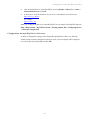
Configuration through Digi Device Discovery
A subset of configuration settings can be changed through Digi Device Discovery. When an
attempt is made to change configuration settings is made, a password prompt will be displayed.
Leave the field in the prompt blank and click OK.
43
Configuration from the Web interface
The Home page
When the web interface is opened, the Home page is displayed. The information listed on this page
may vary based on product and supported features. Here is a sample Home page for a ConnectPort
X2e ZB Cellular model.
Device Information
The Device Information section of the Home page summarizes current system parameters and
network connectivity status.
The Network Connectivity Status LED and information displayed indicates the readiness of the
ConnectPort X2e ZB to communicate in a network and with the iDigi server. See the description of
the status LEDs beginning on page 21 and "Troubleshooting" on page 89 for information on the
LED and the various network connectivity status conditions listed.
Refresh button
Clicking Refresh refreshes the Home page. This refresh operation is necessary because things like
system time and network connectivity status are not dynamically updated when the state changes
on the device. This refresh operation also updates device status information.
44
Configuration from the Web interface
Configuration and Administration links
The left side of the Home page has a menu of choices that display pages for configuration and
administration tasks.
The choices under Configuration in the menu display pages for configuring settings for various
features. Some of the configuration settings are organized on sets of linked screens. The choices in
this menu may vary based on product and supported features.
The choices under Administration complete common device administration tasks, and are covered
in "Administration/maintenance" on page 64.
Apply and save changes
The web interface runs locally on the device, which means that the interface always maintains and
displays the latest settings in the Digi device. On each screen, the Apply button is used to save any
changes to the configuration settings to the Digi device.
Cancel changes
To cancel changes to configuration settings, click the Refresh or Reload button on the web
browser. This causes the browser to reload the page. Any changes made since the last time the
Apply button was clicked are reset to their original values.
Restore the Digi device to factory defaults
The device configuration can be reset to factory defaults as needed during the configuration
process. See "Factory reset" on page 26. Note that any network configuration settings will have to
be reset after the restore operation is complete.
45
Configuration from the Web interface
Configuration settings pages
Ethernet Network
The Ethernet Network settings display the current IP address and DHCP settings for Ethernet
network communications. The IP address can be changed, either by obtaining a new one through
DHCP or by entering a static IP address.
The Domain Name Service Configuration show the two Domain Name System servers to be used
as static servers when dynamic mechanisms do not supply enough DNS servers.
The iDigi Service Configuration has one setting, Server Address. This setting is the address of
the iDigi server used to manage the ConnectPort X2e ZB. The Configuration > iDigi
Connectivity page enables or disables the connection to the specified iDigi server.
Wireless Network
The Wireless Network settings display the current IP address and DHCP settings for Wi-Fi
network communications. The IP address can be changed, either by obtaining a new one through
DHCP or by entering a static IP address.
Wireless Wizard
The Wireless Wizard link launches a wizard that is used to “teach” a Wi-Fi ConnectPort X2e ZB
device the wireless parameters needed to further configure wireless settings and operation.The
wizard provides a place to copy in the information required for the to connect to your local WiFi
network. In this instance, the ConnectPort X2e ZB is a Wi-Fi “client” connecting to an existing
access point. The information you are required to enter in this wizard should be obtained from the
network administrator for the wireless network the ConnectPort X2e ZB will use. To complete the
wizard:
1
Enter the SSID, or choose an SSID from the list of values, if supplied. This selection is
required.
2
Select the type of network security used on the wireless network.
3
Depending on the network security type, additional parameters can be entered.
4
Messages are displayed while the parameters are being processed and when the wizard is
complete.
For security reasons, the wireless configuration resulting from running this wizard cannot be
viewed, only modified by re-running the wizard.
46
Configuration from the Web interface
Mobile Connectivity settings
The Mobile Connectivity settings identify the service provider to use in connecting to the mobile
network. Information displayed varies by product and whether the device is GSM- or CDMAbased. In addition, the Short Message Service (SMS) can be enabled and configured on this page.
For GSM-based devices, enter the information for your account received from the mobile service
provider.
Current Status: Current status of the cellular modem and mobile connection, including
serial number information, signal strength and quality, and connection state.
Current Settings: For GSM-based devices, the following settings are displayed.
For CDMA-based devices, no settings are displayed.
–
Mobile APN: The service plan or access point name (APN).
–
Username: The username of the mobile connection needed to access the mobile
network. Depending on mobile service provider, this value may not be necessary.
–
Password: The username of the mobile connection needed to access the mobile
network. Depending on mobile service provider, this value may not be necessary.
–
SIM PIN: A password that allows an administrator user of the device to access
information on the SIM card. The password is usually between four and eight digits.
SIM PINs act like ATM PINs in that they require users to authenticate themselves as the
true owner of the card before information is released. Depending on mobile service
provider, this value may not be necessary.
47
Configuration from the Web interface
Short Message Service (SMS) Settings: These options configure the cellular Short
Message Service (SMS) capabilities of the cellular modem.
–
Enable cellular Short Message Service (SMS) services: Enables or disables SMS
features on this Digi device. When this option is enabled, the remaining SMS options
may be configured. This option is enabled (on) by default and can be disabled if desired.
When SMS services are disabled, all SMS-related menu items in the web interface and
iDigi are disabled/grayed-out.
–
iDigi SMS Settings: These settings configure the iDigi device to be managed by iDigi
via Short Message Service (SMS) messages.
–
Enable iDigi SMS: Enables or disables iDigi SMS support.
–
Opt-in: Enables or disables the iDigi SMS opt-in feature. By default, ConnectPort X2e
ZB Cellular models are configured to automatically register with the iDigi Technical
Support when you first power up your device. Activation with iDigi Technical Support
is free. Our iDigi Technical Support team will only access your device upon your
approval. With your consent, the iDigi Technical Support team is afforded visibility and
access to your device to diagnose and resolve issues, should you require assistance. In
the automatic registration process, ConnectPort X2e ZB Cellular models attempt to send
a single SMS message containing the device’s mobile phone number. Your cellular
account must be set up to send and receive SMS messages. Network costs associated
with this single SMS transmission are the customer’s responsibility. Any device
information stored in the iDigi Technical Account is secured with adherence to iDigi’s
security and privacy procedures, and will not be disclosed to, or accessible by third
parties.
–
Restrict Sender: Only process inbound messages for iDigi from the number specified
in the Phone Number setting. Messages from other phone numbers will be passed on to
other SMS Services on the device.
–
Phone Number: The phone number or short code of the iDigi server. This is a setting in
the device that allows the device to send to the iDigi server, and possibly restrict
messages to those coming from the iDigi server. The default value phone number is
32075.
–
Service Identifier: The Service Identifier (prefix) of iDigi. This field is an optional
setting and is used in cases where there is a shared short code in use, and an identifier
(prefix) is required to redirect a message to a specific service under that short code. The
default value is idgp. Use of the Service Identifier idgp is mandatory when the Phone
Number is 32075.
48
Configuration from the Web interface
SureLink™ Configuration settings
Digi SureLink™ is an optional feature that monitors the integrity of an established network
connection. Several settings and tests can be configured to perform a selected test to examine the
functional integrity of the network connection, and take action to recover the connection in the
event that it is lost.
Currently SureLink is supported for cellular communications only.
The Link Integrity Monitoring settings can be configured to perform a selected test to examine
the functional integrity of the network connection, and take action to recover the connection in the
event that it is lost.
Link integrity monitoring settings
Enable Link Integrity Monitoring using the test method selected below: Enables or
disables the link integrity monitoring tests. If this setting is enabled, the other Link
Integrity Monitoring settings may be configured and are used to verify the functional
integrity of the mobile connection. The default is off (disabled).
There are several tests available:
–
Ping Test
–
TCP Connection Test
–
DNS Lookup Test
–
iDigi Connection Test
You can use these tests to demonstrate that two-way communication is working over the
mobile connection. Several tests are provided because different mobile networks or
firewalls may allow or block Internet packets for various services. Select the appropriate
test may be selected according to mobile network constraints and your preferences.
The link integrity tests are performed only while the mobile connection is established. If
the mobile connection is disconnected, the link integrity tests are suspended until the
connection is established again.
For the link integrity tests to provide meaningful results, the remote or target hosts must
be accessible over the mobile connection and not through the LAN interface of the
device (if it has one). That is, the settings should be configured to guarantee that the
mobile connection is actually being tested.
The link integrity test settings may be modified at any time. The changes are used at the
start of the next test interval.
49
Configuration from the Web interface
Ping Test: Enables or disables the use of “ping” (ICMP) as a test to verify the integrity
of the mobile connection. The test is successful if a valid ping reply is received in
response to the ping request sent. The ping test actually sends up to 30 ping requests, one
per second, to test the link. When a valid reply is received, the test completes
successfully and immediately. If a reply is received for the first request sent, there is no
need to send the other two requests.
Two destination hosts may be configured for this test. If the first host fails to reply to all
three ping requests, the same test is attempted to the second host. If neither host replies
to any of the ping requests sent, the test fails. The primary and secondary addresses may
be either IP addresses or fully qualified domain names.
–
Primary Address: First host to test.
–
Secondary Address: Second host to test (if the first host fails).
TCP Connection Test: Enables or disables the creation of a new TCP connection as a
test to verify the integrity of the mobile connection. The test is successful if a TCP
connection is established to a specified remote host and port number. If the remote host
actively refuses the connection request, the test is considered a failure. The TCP
connection test waits up to 30 seconds for the connection to be established or refused.
When the TCP connection is established, the test completes successfully, and the TCP
connection is closed immediately.
Two destination hosts may be configured for this test. If the first host fails to establish
(or refuse) the TCP connection, the same test is attempted to the second host. If neither
host successfully establishes (or refuses) the TCP connection, the test fails. The primary
and secondary addresses may be either IP addresses or fully qualified domain names.
–
TCP Port: The TCP port number to connect to on the remote host. The default is 80.
DNS Lookup Test: Enables or disables the use of a Domain Name Server (DNS) lookup
as a test to verify the integrity of the mobile connection. The test is successful if a valid
reply is received from a DNS server. Typically, this means the hostname is successfully
“resolved” to an IP address by a DNS server. But even a reply such as “not found” or
“name does not exist” is acceptable as a successful test result, since that demonstrates
successful two-way communication over the mobile connection. When a valid reply is
received, the test completes successfully and immediately.
The DNS servers used in this test for the hostname lookup, are the primary and
secondary DNS servers obtained from the mobile network when the mobile PPP
connection is first established. These addresses can be viewed on the
Administration > Mobile Status page.
iDigi Connection Test: Enables or disables verification of the iDigi connection. The
test is successful if a connection can be established to the configured iDigi server, and if
keep-alive messages can be exchanged with the server. The test fails if a connection
cannot be established, the connection is closed, or if keep-alive messages stop. The
iDigi server is configured on the Configuration/iDigi Connectivity page.
50
Configuration from the Web interface
Repeat the selected link integrity test every N seconds: Specifies the interval, in
seconds, at which the selected test is initiated (repeated). A new test will be started every
N seconds while the mobile connection is established. This value must be between 10
and 65535. The default is 240. This setting is used by Ping, TCP Connection, and DNS
Lookup tests only, not iDigi Connection.
If the configured interval is less time than it takes a test to complete, the next test will
not be initiated until the previous (current) test has completed.
Test only when idle if no data is received for the above period of time: Specifies that
the test repeat interval (above) is to be used as an idle period interval. That is, initiate the
selected link integrity test only after no data has been received for the specified interval
of time. This changes the behavior of the test in that the test interval varies according to
the presence of other data received from the mobile connection. This setting is used by
Ping, TCP Connection, and DNS Lookup tests only, not iDigi Connection.
Although using this idle option may result in less data being exchanged over the mobile
connection, it also prevents the link integrity tests from running as often to verify the
true bi-directional state of that connection.
Reset or Reconnect the link after the following number of consecutive link integrity
test failures: Specifies that after the configured number of consecutive link integrity test
failures, the mobile connection should be either reset or reconnected:
–
Reset: The cellular modem is reset.
–
Reconnect: The mobile interface is reconnected.
This value must be between 1 and 255. The default is 3. When the mobile connection is
reestablished, the “consecutive failures” counter is reset to zero.
If the mobile connection is disconnected for any reason (including not as a result of a
link integrity test failure), the consecutive failures count is reset to zero when the mobile
connection is reestablished.
Primary Test Hostname:
Secondary Test Hostname:
These settings apply to Ping, TCP Connection, and DNS Lookup tests only. Two
hostnames may be configured for the link integrity monitoring test. Hostnames can be
specified in the form of domain names or IP addresses. If the first hostname fails to get a
reply, the same test is attempted for the second hostname. If no reply is received for
either hostname, the test fails. The primary and secondary DNS names should be fully
qualified domain names. Note that the reverse lookup of an IP address is possible, but
that is usually unlikely to succeed in returning a name. Still, such a reverse lookup can
be used to demonstrate the integrity of the mobile connection.
–
Primary Test Hostname: The first hostname to look up.
–
Secondary Test Hostname: The second hostname to look up (if the first hostname
fails).
Status and statistical information for mobile connections
Once the mobile settings have been configured, you can monitor the status of mobile connections
by going to Administration > Mobile Status. See "Mobile Status" on page 67.
51
Configuration from the Web interface
Python: configure automatic starting and exit conditions for Python programs
The Python Autostart Configuration page configures the automatic starting of Python programs
that are loaded on the ConnectPort X2e ZB device. See "File management" on page 65 for details
on loading files. These programs are executed through the specified “python” commands.
Select the Enabled checkbox to set the program to be automatically started at system startup.
In the Command field, enter the name of the Python file to be started, and any program arguments.
The On Exit Action setting controls the action to be performed in the event the program exits.
Do Nothing: Continue device operation without doing anything about the program.
Reboot: Reboot the device.
Restart the Script: Restart the Python program.
For example:
52
Configuration from the Web interface
Network Services
The Network Services page enables or disables common network services that are available on the
ConnectPort X2e ZB, and configures the network port on which the service is listening. Disabling
services may be done for security purposes. That is, certain services can be disabled so the device
runs only those services specifically needed and to improve device security.
The only configurable network services on the ConnectPort X2e ZB are HTTP, HTTPS, and SSH.
Following is more information about each service and its default network port number. It is usually
best to use the default network port numbers for these services because they are well known by
most applications.
Default
network
port
number
Service
Services provided
HyperText Transfer Protocol
(HTTP), also known as Web Server
Access to web pages for configuration that can be secured by
requiring a user login. HTTP and HTTPS, below, are also
referred to as Web Server or Secure Web Server. These services
control the use of the web interface. If HTTP and HTTPS are
disabled, device users cannot use the web interface to configure,
monitor, and administer the device.
80
HyperText Transfer Protocol over
Secure Socket Layer (HTTPS), also
known as Secure Web Server
Access to web pages for configuration that can be secured by
requiring a user login with encryption for greater security.
443
Secure Shell Server (SSH)
Allows users secure access to log in to the Digi device and
access the command-line interface.
22
Time
The Time Configuration page configures the various Network Time Protocol (NTP) servers that
the ConnectPort X2e ZB uses to obtain current date and time, and the time zone for the NTP server.
The default settings for this feature are likely to be sufficient for many users.
53
Configuration from the Web interface
iDigi Connectivity
The iDigi Connectivity page enables/disables the connection to the iDigi server used for managing
the ConnectPort X2e ZB device, configures the iDigi server, and configures the proxy server, if
used.
iDigi Connectivity: Enables or disables the connection to the iDigi server.
iDigi Server Name/ iDigi Server Port: Obtain this value from your iDigi server
administrator. Typically this administrator is Digi. If your enterprise has its own iDigi
server rather than one provided by Digi, enter your enterprise-specific iDigi server
information here.
Proxy Server Name/port: These values configure which system will provide network
access, and which port number will forward network connection attempts to the iDigi
server. Obtain these values from your iDigi server administrator.
54
Configuration from the Web interface
XBee Network
The ConnectPort X2e ZB provides a gateway between an Internet Protocol (IP) network and a
network of various wireless devices containing XBee RF modules. Typically, these XBee devices
are small sensors and controllers.
Current Devices: Displays a view of XBee network devices, including the
ConnectPort X2e ZB gateway and any nodes that have been discovered by the XBee
module in the ConnectPort X2e ZB gateway. Each node displayed provides this
information:
Node ID: A descriptive, user-friendly name for the device. The Node ID is a 20-byte
printable ASCII string that allows for referencing devices by names rather than their
physical addresses.
Network: A 16-bit network address for the device.
Extended address: A static 64-bit address for the device that is a guaranteed to be
unique.
Node type: The node type for the device, or role it plays in the XBee network:
coordinator or router.
Product type: A description of the product type for the node, such as “X2e Gateway.”
Apply: Applies the changes to the Node ID for the node.
Refresh: refreshes the list of nodes that have joined the XBee network. (Note that the
discovery operation may take a few seconds.) Refresh lists only nodes that respond to
the discovery operation. Previous nodes are cleared from the list. Sleeping or
unresponsive nodes may not be listed immediately, but may later appear in the list.
55
Configuration from iDigi Manager Pro
Configuration from iDigi Manager Pro
The iDigi User’s Guide describes how to set up an iDigi account and add devices to the iDigi
Manager Pro device list. Once your ConnectPort X2e ZB is added to the device list, you can view
the device in the device list and access its configuration settings.
56
Configuration from iDigi Manager Pro
Basic configuration settings
In the iDigi Manager Pro interface, basic configuration settings for the ConnectPort X2e ZB are
accessed by right-clicking the device in the device list and selecting Properties. The basic
configuration settings located in this menu are:
Ethernet settings
Wi-Fi settings
Domain Name Server (DNS)
Python
There are several other operations on the context menu, such as File Management,
System Information, and Connection History. These operations are important for administrative
and troubleshooting tasks and are discussed elsewhere in this guide.
Advanced configuration settings
Advanced configuration settings for the ConnectPort X2e ZB are accessed by right-clicking the
device in the device list and selecting Properties > Advanced Configuration. The settings
available in this menu vary by model.This section discusses several but not all Advanced
Configuration settings.
Mobile Connectivity
The Mobile Connectivity settings identify the service provider to use in connecting to the mobile
network. Information displayed is currently the same for GSM- or CDMA-based products. Some
values may be hidden, depending on your model.
For GSM-based devices, these settings are relevant and are based on account information received
from your mobile service provider.
GSM access point name: The service plan or access point name (APN).
User password: The password for the User login of the mobile connection needed to
access the mobile network. Depending on mobile service provider, this value may not be
necessary.
SIM PIN code: A password that allows an administrator user of the device to access
information on the SIM card. The password is usually between four and eight digits.
SIM PINs act like ATM PINs in that they require users to authenticate themselves as the
true owner of the card before information is released. Depending on mobile service
provider, this value may not be necessary.
User login: The username of the mobile connection needed to access the mobile
network. Depending on mobile service provider, this value may not be necessary.
57
Configuration from iDigi Manager Pro
SureLink settings
Digi SureLink™ is an optional feature that monitors the integrity of an established network
connection. Several settings and tests can be configured to perform a selected test to examine the
functional integrity of the network connection, and take action to recover the connection in the
event that it is lost.
Currently SureLink is supported for cellular communications only.
The SureLink settings can be configured to perform a selected test to examine the functional
integrity of the network connection, and take action to recover the connection in the event that it is
lost.
SureLink enable: Enables or disables the SureLink feature and the specified link
integrity monitoring tests. The default is off (disabled).
Test interval: The interval, in seconds, at which the selected test is initiated (repeated).
A new test will be started every N seconds while the mobile connection is established.
This value must be between 10 and 65535. The default is 240. This setting is used by
Ping, TCP Connection, and DNS Lookup tests only, not iDigi Connection.
If the configured interval is less time than it takes a test to complete, the next test will
not be initiated until the previous (current) test has completed.
Test only if link is idle: Whether the test repeat interval (above) is to be used as an idle
period interval. That is, initiate the selected link integrity test only after no data has been
received for the specified interval of time. This changes the behavior of the test in that
the test interval varies according to the presence of other data received from the mobile
connection. This setting is used by Ping, TCP Connection, and DNS Lookup tests only,
not iDigi Connection.
Although using this idle option may result in less data being exchanged over the mobile
connection, it also prevents the link integrity tests from running as often to verify the
true bi-directional state of that connection.
Number of consecutive failures to cause recovery action: Specifies that after the
configured number of consecutive link integrity test failures, the mobile connection
should be disconnected and reestablished. This value must be between 1 and 255. The
default is 3. When the mobile connection is reestablished, the “consecutive failures”
counter is reset to zero.
If the mobile connection is disconnected for any reason (including not as a result of a
link integrity test failure), the consecutive failures count is reset to zero when the mobile
connection is reestablished.
58
Configuration from iDigi Manager Pro
Host List: Two hostnames may be configured for this test. Hostnames can be specified
in the form of domain names or IP addresses. If the first hostname fails to get a reply, the
same test is attempted for the second hostname. If no reply is received for either
hostname, the test fails. The primary and secondary DNS names should be fully
qualified domain names. Note that the reverse lookup of an IP address is possible, but
that is usually unlikely to succeed in returning a name. Still, such a reverse lookup can
be used to demonstrate the integrity of the mobile connection.
–
Primary Test Hostname: The first hostname to look up.
–
Secondary Test Hostname: The second hostname to look up (if the first hostname
fails).
TCP test port number: The TCP port number to connect to on the remote host. The
default is 80.
Test type: There are several tests available:
–
Ping Test
–
TCP Connection Test
–
DNS Lookup Test
–
iDigi Connection Test
For descriptions of these tests, see page 50.
Link failure action: The action to be performed when a link failure is detected:
–
Reset modem: Reset the cellular modem in the ConnectPort X2e ZB device.
–
Reconnect interface: Reconnect the cellular interface.
59
Configuration from iDigi Manager Pro
XBee Networks page
Clicking the XBee Networks menu within the iDigi Manager Pro tab opens the
XBee Networks page. This page allows you to manage all the XBee Nodes in your inventory.
The iDigi User’s Guide provides describes the settings and operations that can be performed from
the XBee Networks pages and menus.
60
Configuration from iDigi Manager Pro
XBee RF module settings
The configuration information for an XBee node is displayed by opening its Properties page.
To do this, either double-click on the node in the XBee Networks page, or right-click the node
and select Properties or click the Properties toolbar button. The Basic Settings control basic
operation of the XBee module in an XBee network. Advanced radio settings control behavior of
the XBee module at a more detailed level. The Summary view provides an overview of current
XBee RF module operational and state information.
If you select multiple devices, multiple Properties pages will be open corresponding to each
device that was selected.
61
Configuration from iDigi Manager Pro
SMS settings
There are three groups of SMS settings and tasks in the iDigi Manager Pro interface from the rightclick menu for the ConnectPort X2e ZB Cellular models:
Properties > Advanced Configuration > Cellular SMS
Properties > Advanced Configuration > iDigi SMS
SMS > SMS commands | Configure
Properties > Advanced Configuration > Cellular SMS
Enabled: This setting enables or disables all SMS features on this Digi device. When this option is
enabled, the remaining SMS options may be configured. This option is disabled (off) by default.
Properties > Advanced Configuration > iDigi SMS
These settings configure the iDigi device to be managed by iDigi via Short Message Service (SMS)
messages.
State: Enables or disables iDigi SMS support.
Restrict Sender to only iDigi Server Phone Number: Only process inbound messages
for iDigi from the number specified in the Phone Number setting. Messages from other
phone numbers will be passed on to other SMS Services on the device.
–
iDigi Server Phone Number: The phone number or short code of the iDigi platform.
For more information about the iDigi SMS Phone Number and Service ID fields, contact
your Digi sales Representative, or use the iDigi Provision command. The default value
for the phone number is 32075.
iDigi Server Service Identifier: The Service Identifier (prefix) of iDigi. This field is an
optional setting and is used in cases where there is a shared short code in use, and an
identifier (prefix) is required to redirect a message to a specific service under that short
code. The default value is idgp.
62
Configuration from iDigi Manager Pro
SMS > SMS commands | Configure
Right-clicking the device and selecting SMS from the menu displays a set of SMS commands and
an option to configure settings. Of the commands displayed in the list, the only ones currently
supported are:
Request Connect
SMS > Request Connect sends an SMS message from iDigi to the iDigi device, calling it
back to establish an EDP connection with the iDigi cloud server.
Reboot
SMS > Reboot sends an iDigi SMS message to the device to reboot itself.
Configure
SMS > Configure registers the phone number of your cellular device, allowing iDigi to send
messages to it. For details on these settings, see the iDigi User’s Guide topic ”Configure the
Device’s Phone Number.”
63
Common administrative tasks
Administration/maintenance
C
H
A
P
T
E
R
4
This chapter describes the administrative and maintenance tasks that need be performed for the
ConnectPort X2e ZB periodically. It covers common administrative tasks and how to perform them
through iDigi Manager Pro and the web interface.
Common administrative tasks
For the ConnectPort X2e ZB, common administrative tasks include:
Firmware updates
File management
Rebooting the device
Firmware updates
There are two types of firmware updates for the ConnectPort X2e ZB:
Firmware updates for the gateway operating system
Firmware updates for the for the XBee RF module on the gateway and nodes
Gateway operating system firmware update s
Gateway operating system firmware updates for the ConnectPort X2e ZB can be downloaded from
the Digi Support site. They can then be loaded through the web interface or iDigi Device Manager
Pro.
The gateway operating system can only be upgraded, not downgraded, through the web interface or
iDigi Manager Pro. The firmware image contains a certificate that is verified before an upgrade can
be accepted by the gateway.
64
Common administrative tasks
XBee RF module firmware updates
Updating the firmware for XBee RF modules involves two firmware update scenarios:
Update firmware for the XBee module on the gateway
Update firmware on XBee modules on nodes elsewhere in the network. This type of
update is known as an over-the-air (OTA) firmware update.
Download firmware update files from Digi
There is only one firmware file for the XBee RF module in ConnectPort X2e ZB products. It is
named XBP24-S2C_40XX.ebl, where XX is the firmware version.
This firmware is located on the Digi Support site at:
Support->XBee/XBee-PRO ZB SMT (S2C)Modules->Firmware Updates
From this location, you will download the .zip file; the .ebl file is included in the .zip file.
Then, you can use the Firmware Update function from the web interface or iDigi Manager Pro to
update the firmware.
File management
A file management feature is provided to manage custom applications, their associated data files,
and other files. It is also possible to push firmware update files to the device filesystem, and to pull
log files from the device filesystem. The device filesystem is described on page 94.
Reboot device
The device can be rebooted as needed from the web interface or iDigi Manager Pro.
65
Administration from the Web interface
Administration from the Web interface
Firmware Update
The Firmware Update page updates the gateway operating system firmware. (Firmware updates
for the XBee RF module on the gateway or nodes are done on the XBee Firmware Update page.)
Volume Information: Displays the current directory and free space remaining.
Firmware Information: Displays the current firmware version running on the device,
and its state: Running, Updating, Recent update failed.
Upload to Current Directory: Uploads the firmware file to the current directory. Use
the Browse button to choose the file on your PC that is the firmware update image.
Click Update Firmware to pull the file from the PC into the device, then attempt a
firmware update with the selected image.
XBee Firmware Update
The XBee Firmware Update page updates the firmware for the XBee RF module on the gateway.
Volume Information: Displays the current directory and free space remaining.
Firmware Information: Displays the current firmware version running on the device,
and its state.
Upload to Current Directory: Uploads the firmware file to the current directory. Use
the Browse button to choose the file on your PC that is the firmware update image. Then
use the Upload file button to upload the XBee firmware file to the /userfs/WEB/mesh
directory in ConnectPort X2e ZB filesystem.
Select the appropriate firmware file from the File List, and then click the
Update XBee Firmware button to attempt a firmware update with the selected image.
XBee Status
The XBee Status page displays status information for the XBee RF module on the gateway. The
parameters displayed vary based on the capabilities supported by XBee RF module; common
parameters include the PAN ID, firmware and hardware versions, and the device type identifier.
See the XBee/XBee-PRO ZB SMT RF Modules Product Manual for parameter descriptions.
66
Administration from the Web interface
Mobile Status
The Mobile Status page items are specific to a cellular modem or service provider account. These
vary in the information reported from modem to modem and also differ between CDMA and GSM
services. Whether a value is displayed depends on the modem type and connection state; if there is
no value for a status field, it is not displayed. This information can be useful for troubleshooting
and technical support. Following are example Mobile Status pages for ConnectPort X2e ZB GSM
and CDMA models. Descriptions of the status fields follow.
67
Administration from the Web interface
Status field
Cellular
modem
type
Description
Device type
Both
The type of cellular modem. For CDMA devices, the value for this
field is CDMA. For GSM devices, the value for this field is GSM.
Manufacturer
Both
Manufacturer of the cellular modem.
Model
Both
Manufacturer’s model number for the cellular modem.
Revision
Both
Manufacturer’s version number for the software running on the cellular
modem.
Serial number
Both
Manufacturer’s serial number for the cellular modem.
Phone number
Both
The phone number stored on the SIM (for GSM) or cellular modem
(for CDMA). The SIM may not have a number stored, or it may not be
correct.
SIM IMSI
GSM
The International Mobile Subscriber Identity (IMSI) for the SIM card.
This value can be considered account number for the mobile
subscriber.
SIM ICCID
GSM
The Integrated Circuit Card Identifier (ICCID) for the SIM card. This
value can be considered as the serial number of the SIM card itself.
SIM PIN status
GSM
Indicates whether a PIN needs to be entered to unlock the SIM card.
There area many possible status values; some common ones are:
READY: SIM is ready. PIN has been entered or no PIN is needed.
SIM PIN: PIN is required to unlock the SIM. It can be entered on
the Mobile Configuration page.
SIM PUK, SIM PIN2, SIM PUK2, and similar codes: SIM is
locked and cannot be unlocked by the ConnectPort X2e ZB
Cellular device. It must be placed in another device or phone to be
unlocked.
Error: SIM not inserted or other SIM problem
SIM slot index
GSM
Displayed for products that support multiple SIMs only. Indicates
which SIM slot is currently in use by the device. 0 means the first slot,
1 means the second slot.
MEID
CDMA
Mobile equipment identifier (MEID), globally unique number
identifying a physical piece of CDMA mobile station equipment.
PRL version
CDMA
Preferred Roaming List version number. Updates are done at the same
time as provisioning.
68
Administration from the Web interface
Status field
Cellular
modem
type
Description
Provisioning status
CDMA
Specifies the status of the provisioning process for the cellular modem,
in which it is configured with the required information used to access
the cellular network.
Not provisioned: Modem has not yet provisioned. Contact your
mobile service provider to make sure your device is registered in
your mobile account.
Provisioned: Modem is configured and ready to use
In progress: Modem is now being provisioned
Failed: Provisioning was unsuccessful. This may be caused by a
poor signal, or the cellular modem not being activated with the
carrier.
Signal strength
Both
Received cellular signal strength indicator (RSSI). A measure of the
signal level of the network.
Different RSSI levels are used GSM vs. CDMA to determine the
number of bars.
For GSM: -108 or more is 1 bar, -93 is 2, -77 is 3
For CDMA: -105 or more is 1 bar, -90 is 2, -75 is 3
Signal level
Both
An indicator of the received cellular signal, in bars.
0: No signal
1: Poor signal
2: Adequate signal
3: Good signal
Signal quality
Both
An indicator of the quality of the received cellular signal, measured in
dB.This value is also known as Ec/Io.
Registration status
Both
The status of the cellular modem’s connection to a cellular network.
Not registered
Registered (Home network)
Searching for Network
Not Registered (Access Denied)
Not Available (Reason not Known)
Registered (Roaming)
Cell ID
GSM
Identifier of the cellular base station with which the cellular modem is
registered.
System ID
CDMA
The system identification number of the cellular network with which
the cellular modem is registered.
69
Administration from the Web interface
Status field
Cellular
modem
type
Description
Network ID
CDMA
The network identification number of the cellular network with which
the cellular modem is registered.
Location area code
GSM
Identifier of the location of a group of cellular base stations with which
the cellular modem is registered, in hexadecimal format.
Mobile country code
Mobile network code
GSM
These codes are used to uniquely identify a mobile phone operator/
carrier with which the cellular modem is registered.
Operator name
GSM
The name of the mobile operator with which the modem is registered.
This corresponds to the mobile country and network codes.
Band
GSM 2G
service only
The radio frequency band being used by the modem.
For GSM, the band can be one of the following:
GSM 850
GSM 900
DCS 1800
PCS 1900
Future modems may have different values.
Service
CDMA
The type of data service provided by the cellular network. For CDMA,
the data service is one of the following:
None
1xRTT
EVDO Rev 0
EVDO Rev A
Future cellular modems may have other values.
Channel
Both
Radio channel being used by the cellular modem.
Profile
Both
The current set of mobile configuration settings used to configure the
cellular modem. ConnectPort X2e ZB Cellular products always use
profile 0.
70
Administration from the Web interface
Status field
Cellular
modem
type
Description
Connection state
Both
The operating state of the cellular modem:
Initializing: Modem is being reset and configured
Registering: Modem is searching for a network
Delay before connecting: Modem is delaying after an
unsuccessful connection (Verizon only)
Connecting: Mobile data connection is being established
Connected: Mobile data connection is active
Disconnecting: Mobile data connection is ending
Disconnected: Mobile data connection has ended. See Disconnect
reason for the cause.
Disabled: Mobile data connection is not enabled by configuration
settings (not on X2e yet)
Provisioning: Modem is being provisioned with the mobile carrier
(CDMA only)
PRL update: Preferred roaming list is being updated (CDMA, not
on X2e yet)
Operator scan: Modem is searching for available mobile operators
(GSM, not on X2e yet)
No device found: Modem is not available or is malfunctioning
Connection duration
Both
Amount of time the current mobile data connection has been active.
The format is N days HH:MM:SS.
Connection error
Both
Displayed after a connection error occurs only. Indicates the reason the
previous connection attempt failed:
SIM PIN required: The SIM PIN must be entered on the Mobile
Configuration page.
SIM PIN incorrect: The SIM PIN entered does not match the
actual one for the SIM.
SIM not ready: No SIM inserted or other SIM problem.
Not registered: Modem did not register with a cellular network.
Dial failed: Error starting data connection.
Authentication failed: Incorrect login or password entered on the
Mobile Configuration page.
Connection timeout: Connection did not complete.
Device reset error: Modem could not be reset.
Device open error: Modem is malfunctioning.
Device config error: Modem could not be configured.
PPP error: Internal system error
71
Administration from the Web interface
Status field
Cellular
modem
type
Description
Disconnect reason
Both
Displayed after a previous connection was ended. Indicates the reason
the previous connection was ended:
User requested: Initiated by user action.
Network disconnect: Initiated by cellular network or carrier.
Carrier loss: Poor signal or disconnected by network.
Connection timer: Connection did not complete.
Receive idle timer: No data received for configured receive idle
time.
Device monitoring error: Error while monitoring the modem status.
May indicate a malfunctioning modem.
IP address
Both
Internet protocol address of the mobile data interface. The device may
be contacted at this IP address if permitted by the carrier.
Peer address
Both
Internet protocol address of the mobile data server. This IP address is
typically provided as background information, and not normally used
to communicate with the device.
DNS primary address
Both
IP address of the primary Domain Name System (DNS) server
assigned by the mobile carrier. This server resolves domain names to
IP addresses.
DNS secondary address
Both
IP address of the backup DNS server assigned by the mobile carrier.
Receive idle time
Both
The amount of time since data was last received by the cellular modem.
Transmit idle time
Both
The amount of time since data was last transmitted by the cellular
modem.
Connections
Both
The number of mobile data connection attempts since the ConnectPort
X2e ZB Cellular device was started.
Connection errors
Both
The number of unsuccessful mobile data connection attempts since the
ConnectPort X2e ZB Cellular device was started.
Carrier loss
Both
The number of times the connection was lost because of poor signal or
being disconnected by the network.
LCP echo failed
Both
The number of Link Control Protocol (LCP) echo requests that have
been sent after a “quiet” interval to test the cellular link and/or keep it
alive that have failed. Not used by ConnectPort X2e ZB Cellular
products.
72
Administration from the Web interface
Status field
Cellular
modem
type
Description
Idle timeout
Both
The number of connection resets because the idle timeout was reached/
exceeded for transmitted and received data.
User disconnect
Both
The number of disconnects of the cellular connection performed by
device users. This type of user disconnect is currently only done by a
user when provisioning the cellular modem,
Monitoring errors
Both
Number of errors encountered while monitoring the cellular modem
status. May indicate a malfunctioning modem.
Device resets
Both
Number of cellular modem resets caused by errors, failed connection
attempts, or user requests.
Received bytes
Both
Number of bytes received by the cellular modem during the current
data session.
Transmitted bytes
Both
Number of bytes transmitted by the cellular modem during the current
data session.
Total received bytes
Both
Total number of bytes received by the modem since the ConnectPort
X2e ZB Cellular device was started.
Total transmitted bytes
Both
Total number of bytes transmitted by the modem since the ConnectPort
X2e ZB Cellular device was started.
73
Administration from the Web interface
File Management
The File Management page loads files onto the ConnectPort X2e ZB and displays current
information about loaded files. For a description of the filesystem layout, see page 94.
Volume Information: Displays the current directory for loading files and free space
remaining.
Note: Digi recommends using no more than 20 MB for custom applications, as the
ConnectPort X2e ZB requires a portion of the same space to be capable of managing
persistent system logs and firmware updates.
Upload to Current Directory: Uploads files to the current directory. Use the Browse
button to find a file on your PC to be uploaded to the ConnectPort X2e ZB. Click
Update file to begin the file upload process.
File List: A listing of the “current directory” (as noted in the Volume Information
area) on the device.
–
Open: Opens a directory after it is selected in the file list. The “current directory” will
change and the list will be updated.
–
Make Directory: Creates a new, empty directory in the “current directory.”
–
Save As: Downloads a regular file from the filesystem to your local PC.
–
Remove: Deletes files or, for directories, empty directories only.
Refresh button: Reloads all the information on the page.
74
Administration from the Web interface
System Log
The System Message Log File Browser is a diagnostic tool that allows viewing entries in a system
log file. The default log file that can be viewed from this browser is eventlog.txt. This file is the
primary message log for informational notices.
There are other system log file that are available for debugging specific parts of the system. Note
that these log files have a fixed size and roll over when the maximum size is reached. When the file
rolls over, a single secondary file is created with the extension .0 . For example, when xbee.log
rolls over, the older data will be stored in xbee.log.0. When both files have reached their maximum
size, the older file will be overwritten. Also note that many of the log files are stored in persistent
memory (flash) and will contain data from multiple boots. The only exception is xbee.log, which is
stored in a RAM disk.
Logging is always enabled and is not user-configurable. When the Digi device operates in an
unexpected manner, the log entries can be sent to Digi for analysis by Technical Support and
Engineers. The event log cannot be turned off, so that Digi receives an accurate view of all aspects
of the operation of the device.
75
Administration from the Web interface
Available log files and contents
The following log files are available:
Log file
Contents
eventlog.txt/
eventlog.txt.0
High-level system messages.
python.log/
python.log.0
Captures any output of Python programs that were started with
the Python auto-start feature.
xbee.log/
xbee.log.0
A non-persistent log file that records all XBee traffic.
digi.log/
digi.log.0
For internal use only. This file may be requested by the Digi
technical support group.
sef.log/sef.log.0
For internal use only.
The Message Filters allow Digi Technical Support working with customers on troubleshooting
issues to more quickly hone in on areas of interest in the log file as needed.
Reboot
To reboot the ConnectPort X2e ZB, click the Reboot menu option. Wait approximately 1 minute
for the reboot to complete.
76
Administration from iDigi Manager Pro
Administration from iDigi Manager Pro
In iDigi Manager Pro, administration tasks are organized in the right-click menu for the
ConnectPort X2e ZB, under Administration and Firmware. The File Management task is
launched from a link in the device Properties page.
77
Administration from iDigi Manager Pro
Restore Factory Defaults
Administration > Restore Factory Defaults restores the factory default configuration to the
selected device or devices. The only supported choice is to reset all the configuration settings.
Reboot
Administration > Reboot reboots the selected device or devices.
Disconnect
Administration > Disconnect disconnects the device from iDigi. If the device is configured to
automatically reconnect to iDigi, it will re-establish the connection to iDigi after its
reconnection timeout period has expired.
Firmware
The Firmware options perform several types of firmware updates.
Update Firmware: Gateway operating system firmware update s
Firmware > Update Firmware updates the gateway operating system firmware from a specified
firmware file. In the dialog, select a firmware file to upload to the selected device or devices. Once
the firmware file is downloaded to the device, the device will be rebooted automatically.
Update Gateway XBee Radio Firmware
Firmware > Update Gateway XBee Radio Firmware updates the firmware on the XBee RF
module on the ConnectPort X2e ZB. In the dialog, select an XBee radio firmware file to upload to
the selected device or devices. Once the XBee radio firmware file is downloaded to the device, the
device will be rebooted automatically.
Update XBee Node Firmware
Firmware > Update XBee Node Firmware updates the XBee firmware for the selected remote
node. Once the XBee radio firmware file is downloaded to the remote node, the remote node will
be rebooted automatically.
78
Administration from iDigi Manager Pro
File Management
The File Management task is launched from the Properties page for ConnectPort X2e ZB, by
clicking File Management. This page loads files, such as custom application files, onto the
ConnectPort X2e ZB and displays current information about loaded files. This page can also be
used to download system log files from the ConnectPort X2e ZB to view for troubleshooting or
other purposes. These log files are in the /WEB/logging folder. For a description of the
ConnectPort filesystem layout, see page 94.
Note: Digi recommends using no more than 20 MB for custom applications, as the
ConnectPort X2e ZB requires a portion of the same space to be capable of managing persistent
system logs and firmware updates.
79
Administration from iDigi Manager Pro
The File Management toolbar provides quick access to file management tasks.
Button/
Field
Name
Description
Upload file
Opens a dialog for uploading files to the current folder (directory).
Download file
Downloads the selected file to a PC. You can choose to open the
downloaded file with a specified tool or save it.
Delete
Deletes the selected items.
Refresh
Refreshes the list of folders and files displayed.
Back
Move to the previous folder in folder history.
Forward
Move to the next folder in folder history.
Home
Returns to the root folder.
Current or
destination folder
An editable field that displays the current folder, and which can be used to
enter a different destination directory.
Go
Goes to the directory specified in Current or destination folder field.
System log
There is no browser interface for system logs in the iDigi interface. Instead, to view logs, use the
File Management page to navigate to the directory WEB/logging in the ConnectPort X2e ZB
filesystem, and access the log files digi.log, xbee.log, and python.log, and others using the
Download file button. These files are read-only. For more information on these log files, see
page 75.
80
Administration from iDigi Manager Pro
System information
The System Information pages display general system information and system statistics. This
information is typically used by technical support to troubleshoot problems. For example, here is
the information for the mobile (cellular) interface.
81
Programming
C
H
A
P
T
E
R
5
The ConnectPort X2e ZB offers a variety of interfaces that produce and/or consume data.
Developing software programs for ConnectPort X2e ZB products allows Digi customers to provide
custom logic to control the flow information to and from these interfaces. This chapter introduces
the Digi programming tools and resources available to you, and, using annotated example
programs, introduces programming elements and operations available for the ConnectPort X2e ZB.
82
Programming resources
Programming resources
Several tools and resources are available for developing software programs for the
ConnectPort X2e ZB.
Python
Python is a dynamic, object-oriented language for developing software applications, from simple
programs to complex embedded applications. The ConnectPort X2e ZB runs the standard Python
2.7.1 distribution. This Python distribution has a more complete library set than the versions
supported in predecessor gateway products, and integrates well with standard Python.
Digi ESP for Python
Digi ESP for Python is an Integrated Development Environment (IDE) that allows for easy
development of applications in the Python programming language to be loaded, run, tested, and
debugged on the device. This development environment includes a Getting Started Guide that
guides you in creating your first simple application for your ConnectPort X2e ZB, plus extensive
documentation, tutorials, and code samples to help you get started developing custom applications
for your product. Digi ESP for Python is built on Eclipse, an open, extensible IDE, and the Python
Development Environment (Pydev) plug-in.
Unlike proprietary embedded development platforms, the integration of the universal Python
programming language allows for a truly open standard for complete control of connections to
devices, the manipulation of data, and event-based actions.
For example, applications can be created to:
Aggregate data on the gateway throughout the day, then upload to iDigi once a day.
Develop a driver for a custom protocol to talk to device connected to the gateway, such
as devices in an XBee network.
Translate data, for example, from raw serial into an XML format that can be consumed
by other systems, such as iDigi.
The Getting Started Guide shows how to download and install Digi ESP for Python, and how to
launch the Getting Started tutorial to build your first application.
83
Programming resources
Program samples in Digi ESP
Digi ESP for Python provides samples to use as a base for programming the ConnectPort X2e ZB,
including specific examples for exercising specific interfaces available on the ConnectPort X2e
ZB. These program samples can be accessed from the Python or iDigi Dia samples wizard.
1
Go to File > New > Digi Python Application Sample Project or File > New > iDigi Dia
Sample Project. The samples wizard, Python or iDigi Dia, will be opened.
2
Check the option Show only samples compatible with platform. In the combo box, select
ConnectPort X2e ZB or ConnectPort X2e Wi-Fi ZB.
3
The samples in the list will be filtered, and only the ones compatible with the selected
sample will be displayed.; for example:
84
Programming resources
iDigi Dia software
The Digi ESP development environment includes iDigi Device Integration Application (iDigi Dia)
software. This software simplifies connecting devices (sensors, PLCs, etc.) to communication
gateways. It includes a comprehensive library of plug-ins that work out-of-the-box with common
device types and can be extended to include new devices. Its unique architecture allows the user to
add most devices in under a day. iDigi Dia is a tested architecture that provides the core functions
of remote device data acquisition, control, and presentation between devices and information
platforms. It collects data from any device that can communicate with a Digi gateway, and is
supported over any gateway physical interface. iDigi Dia presents this data to upstream
applications in fully customizable formats, significantly reducing a customer’s time to market.
Written in the Python® programming language for use on Digi devices, iDigi Dia can be executed
on a PC for prototyping purposes when a suitable Python interpreter is installed. iDigi Dia is
targeted for applications that need to gather samples of data from a set of devices, such as ZigBee®
sensors, wired industrial equipment, GPS devices, etc. It is an integral component of the iDigi
platform, which customers can deploy with iDigi Dia software to build flexible, robust solutions
with unprecedented speed.
Programming calls through Server Command Interface (SCI) and Remote
Command Interface (RCI)
The iDigi Web Services Server Command Interface (SCI) and the Remote Command Interface
(RCI) can be used as an alternative means of getting settings and state data from the device.
See the SCI (Server Command Interface) chapter of the iDigi Web Services Programming
Guide and the Remote Command Interface (RCI) Specification.
Digi Developer Community Wiki
The Digi Developer Community Wiki provides references for developing solutions using Digi's
communications portfolio, software and services, including Python, iDigi Platform, iDigi Dia, and
more.The Wiki includes how-to's, example code, and M2M information to speed application
development. Digi encourages an active developer community and welcomes your contributions.
http://www.digi.com/wiki/developer/index.php/Main_Page
ConnectPort X2e ZB Wiki
Within the Digi Developer Community Wiki are pages for ConnectPort X2e ZB-specific
programming information, beginning here:
http://www.digi.com/wiki/developer/index.php/ConnectPort_X2e
85
Programming resources
Digi Python Programmer’s Guide
The Digi Python Programmer’s Guide introduces the Python programming language by showing
how to create and run a simple Python program. It reviews Python modules, particularly those with
Digi-specific behavior, and describes how to load and run Python programs onto Digi devices, and
run sample Python programs. This guide is on the Digi Python Wiki; in the Start Here section,
click the link titled Digi Python Programmer's Guide
http://www.digi.com/wiki/developer/index.php/Digi_Python_Programmer%27s_Guide
Python Support Forum on digi.com
Find answers to common questions and exchange ideas and examples with other members of the
Digi Python development community at:
http://www.digi.com/support/forum/listforums?category=25
86
Digi-specific Python modules for programming
Digi-specific Python modules for programming
Several Digi-provided built-in modules apply to functionality in the ConnectPort X2e ZB. To learn
more about these built-in modules, go to:
http://www.digi.com/wiki/developer/index.php/ConnectPort_X2e
From that page, navigate to the information pages on these modules:
digihw: Provides an interface to local hardware.
idigimsg: This is an internal module with functions used by iDigi Dia and Smart Energy
Framework.
rci: Provides a mechanism for processing arbitrary RCI request strings, as well as a
means to set up callbacks to allow Python scripts to respond to remote requests made via
specialized RCI commands.
uptime: Allows access to the Linux gettime function for various clocks.
watchdog: A safeguard that an application can use for critical operations, in which, if
the application threads do not service their watchdog within the promised interval, the
entire system reboots.
xbee: A collection of utility methods for programming the XBee RF module on the
ConnectPort X2e ZB device. It also includes the Python XBee socket interface support.
digisms: For low-level, generic SMS message handling.
idigisms: For communicating using iDigi’s SMS protocol to/from iDigi.
87
Sample programs
Sample programs
These simple annotated samples introduce several programmable features for the ConnectPort X2e
ZB, including button handling, LED control, watchdog, RCI callback, and XBee functions.
Button handling
The following sample program demonstrates functions for handling the button on the
ConnectPort X2e ZB.
import select
fd=open('/var/run/reset_button')
p=select.poll()
p.register(fd, select.POLLPRI)
fd.read()
while True:
p.poll()
fd.seek(0)
val = int(fd.read()[0])
if val:
print "Button pressed!"
else:
print "Button released!"
(1)
(2)
(3)
(4)
(5)
(6)
(7)
Program notes
1
The reset button is exposed as a Linux file. It can be read to determine the state of the button,
and it is possible to block waiting for the button state to change.
2
To block waiting for the button, the standard Python select module is used. This line, and
the line above, demonstrate how to create a polling object that can wait for button state
changes.
3
Read the current value of the button, but forget it. This is done to “clear” the button and
prepare to wait for its state changes.
4
Rather than reading the button in a loop, the system waits for button state changes using the
polling object created earlier.
5
To read the current value, we first “rewind” to the beginning of the “file.”
6
fd.read() gets pending data from the button file. fd.read()[0] returns just the first character
of that data. int(fd.read()[0]) makes explicit the fact that we expect the character we read to
be an integer.
7
If we read a non-zero value, the button is currently pressed.
88
Sample programs
LED control
Controlling the LEDs on the ConnectPort X2e ZB is handled through the user_led_set function.
This sample program controls the Network LED.
Note that if native features are still assigned to the LED, those behaviors will mix with the
behaviors in the sample program.
import digihw
import time
(1)
while True:
digihw.user_led_set(True,1)
time.sleep(1.0)
digihw.user_led_set(False,1)
digihw.user_led_set(True, 2)
time.sleep(1.0)
digihw.user_led_set(False,2)
(2)
(3)
(4)
(5)
Program notes
1
The digihw module includes the user_led_set function needed by the program. user_led_set
has two are two parameters: value and led. The user controlled LED is made to match the
logic state of the “value” parameter. A value of “True” turns on the LED, and a value of
“False” turns it off. The “led” parameter indicates which user LED to blink, with LED 1
being the default.
2
Turn on the “yellow” Network LED.
3
Turn off the “yellow” Network LED.
4
Turn on the “green” Network LED.
5
Turn off the “green” Network LED.
89
Sample programs
Watchdog
The watchdog feature, provided through the watchdog module, exists as a safeguard. If there are
critical operations that “must” happen periodically, or else the system will be irretrievably broken,
an application can request that a “watchdog” be established. If the application threads do not
service their watchdog within the promised interval, the entire system reboots. These software
watchdogs can have their intervals changed, if necessary, and can be deleted. Clearly, use of such a
software watchdog exists as a measure of last resort. Appropriate error detection and handling with
Python scripts is certainly recommended.
The following sample program demonstrates the watchdog feature.
import watchdog
import time
(1)
w=watchdog.Watchdog('test',20)
for x in xrange(1,6):
print "Step ", x
time.sleep(10.0)
w.heartbeat()
print "Step just before the end..."
time.sleep(60.0)
print "Step after the end."
(2)
(3)
(4)
(5)
(6)
(7)
(8)
(9)
Program notes
1
The watchdog module includes the Watchdog class needed by the program.
2
Create a watchdog object named “test” that will expire in 20 seconds.
3
Loop five times (1-5).
4
Indicate our iteration...
5
... sleeping less than the timeout on each iteration, but more time than the timeout in total.
6
Reset the watchdog timer to 20 seconds each iteration, allowing all of the loops to complete.
7
Indicate that small loops are complete.
8
Sleep for an interval much longer than the timeout.
9
This print statement should never be executed, as the system should have rebooted due to
the watchdog timeout expiration.
90
Sample programs
RCI callback
An RCI callback involves two types of actions, demonstrated in the following programs:
Making RCI requests from Python applications
Extending RCI to allow iDigi to make requests of Python applications. This is known as
an RCI callback.
Make an RCI request-example program
import rci
(1)
request_string="""
<rci_request version="1.1">
<query_state>
<interface_info name="eth0">
<ip/>
</interface_info>
</query_state>
</rci_request>
"""
(2)
print rci.process_request(request_string)
(3)
Program notes
1
The rci module includes the process_request function needed by the program.
2
A string representing the RCI request is needed. The sample uses the Python multi-line
string syntax to make it clearer that the XML represents a request for the current IP address
of the Ethernet interface. Combining the lines into a single string on one line would work in
the same way.
3
The RCI XML is submitted for parsing, and the resulting string is returned. In this sample,
the result is simply printed.
91
Sample programs
Make an RCI request-example program
Following is a simple RCI callback example:
import rci
(1)
def cb(req):
print "Received request: " + req
(2)
(3)
r=rci.RciCallback()
r.register_callback('test', cb)
(4)
(5)
rci.process_request('<rci_request version="1.1"><do_command
target="test"><customxml/></do_command></rci_request>')
(6)
Program notes
1
The rci module includes the RciCallback class needed by the program.
2
Create a function to be called whenever a remote entity wishes to communicate with this
script.
3
This simple function will simply demonstrate that it received a request that could be parsed
and handled however the application saw fit.
4
Create a callback object.
5
Assign the target “test” to the new callback object. If a remote entity issues a
“do_command” with the target “test”, the supplied callback function will be called.
6
This is simply an example that causes the callback to be called. This example could also
have been a remote SCI query through iDigi.
92
Sample programs
XBee functions
For a description of the xbee module and program samples, see this Wiki page:
http://www.digi.com/wiki/developer/index.php/Module:zigbee
Sending and receiving SMS messages
For examples of using SMS send/receive in programs, see the ConnectPort X2e ZB program
samples in Digi ESP for Python.
93
The ConnectPort X2e ZB filesystem
The ConnectPort X2e ZB filesystem
The ConnectPort X2e ZB has a Linux-based filesystem. This section gives an overview of the key
directories of the filesystem and common operations performed on directories and files.
Differences between Windows and Linux filesystems
If you are transitioning from a Windows-based filesystem to a Linux filesystem, the following
article covers some of the key differences between Linux and Windows filesystems.
http://freeos.com/articles/3102
Important directories
The files on a Linux system are arranged in what is called a hierarchical directory structure. This
means that they are organized in a tree-like pattern of directories (called folders in other systems),
which may contain files and other directories. The first directory in the file system is called the
root directory. The root directory contains files and subdirectories, which contain more files and
subdirectories and so on and so on. One important difference between the legacy operating system
and Unix-like operating systems such as Linux is that Linux does not employ the concept of drive
letters. While drive letters split the file system into a series of different trees (one for each drive),
Linux always has a single tree. Different storage devices may contain different branches of the tree,
but there is always a single tree.
The frontslash / is used as a directory separator, instead of the backslash \ used in Windows and
DOS.
The /WEB/python/ directory is for user-specific files, such as custom Python applications.
Subdirectories can be created in this area for the customer's applications. This area is read-write.
The /WEB/logging directory contains system log files, including eventlog.txt, python.log,
digi.log, xbee.log, and sef.log. These files are read-only. For more information on these files, see
"System Log" on page 75.
Access/browse the filesystem from device interfaces
There are three aspects or ways in which you will interact with the filesystem resident on the
ConnectPort X2e ZB: through the web interface, and through the command line interface, and
through iDigi.
Common operations for directories and files
The ConnectPort X2e ZB supports standard Linux shell file operations for managing directories
and files. See the command shell reference document listed on page 95 for details on these
operations.
94
The Linux command shell (command-line interface)
The Linux command shell (command-line interface)
A shell is a program that takes commands from the keyboard and gives them to the operating
system to perform. On the ConnectPort X2e ZB, a a program called ash acts as the shell program.
This shell can be useful in several instances, particularly in managing files, executing Python
programs, and programming and executing commands the XBee RF module in the gateway.
Username and password for the Linux command shell
Access to the ConnectPort X2e ZB is at the user level
The username is python.
The password is dbps.
Connect and log on to the device
To connect and log on to the device through the command-line interface:
1
Open a command prompt or terminal window, such as one provided by PuTTY available for
downloading from http://www.putty.org/.
2
From Windows, enter:
putty SSH
When prompted, enter the username: python and the password: dbps
OR
From Linux, enter:
$ ssh python@my_ip_address
Where my_ip_address is the IP address of the ConnectPort X2e ZB. When prompted,
enter the password: dbps
Command shell reference documentation
For more information on the ash shell, see the following document. Note that the ash shell
supported in the ConnectPort X2e ZB is similar, but not identical, to the ash shell described in this
documentation.
http://linux.die.net/man/1/ash
95