1
SiE18-201
Service
Manual
J Series
[Applied Models]
Super Multi Plus : Cooling Only
Super Multi Plus : Heat Pump
SiE18-201
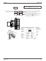
Super Multi Plus
J Series
Heat Pump
Indoor Unit
FTX25JAV1NB
FTX35JAV1NB
FTXD50JV1B
FTXD60JV1B
FTXD71JV1B
FTXD25KZV1B
FTXD35KZV1B
FVX25KZV1B
FVX35KZV1B
CDX25HAV1NB
CDX35HAV1NB
CDX50HAV1NB
CDX60HAV1NB
CDX25JV1NB
CDX35JV1NB
CDX50JV1NB
CDX60JV1NB
FLX25HV1NB
FLX35HV1NB
FLX50JV1B
FLX60JV1B
FHYB35FK7V1
FHYB45FK7V1
FHYB60FK7V1
FHYB71FK7V1
FHYC35B7V1
FHYC45B7V1
FHYC60B7V1
FHYC71B7V1
Outdoor Unit
RMX140JVMB
RMX140JZVMB
BP Unit
BPMK928B42
Table of Contents
BPMK928B43
i
SiE18-201
1. Introduction ........................................................................................... vii
1.1 Safety Cautions ...................................................................................... vii
Part 1
List of Function .................................................................1
1. List of Function........................................................................................2
1.1
1.2
1.3
1.4
Part 2
Function List for Europe R-22.................................................................. 2
Function List for Singapore, Malaysia, Indonesia.................................... 3
Function List for Australia ........................................................................ 4
Function List for Europe R-407C ............................................................. 5
Specifications ...................................................................7
1. Specifications ..........................................................................................8
1.1 Outdoor Units .......................................................................................... 8
1.2 BP Units................................................................................................. 16
1.3 Indoor Units (for Europe) ....................................................................... 17
Part 3
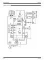
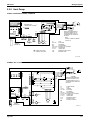
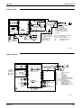
Printed Circuit Board Connector Wiring Diagram
and Name ........................................................................23
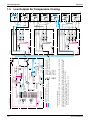
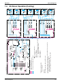
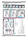
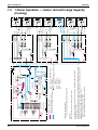
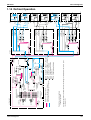
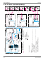
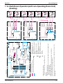
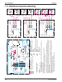
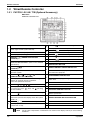
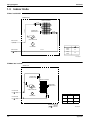
1. Printed Circuit Board Connector Wiring Diagram and Name ................24
1.1
1.2
1.3
1.4
1.5
1.6
Part 4
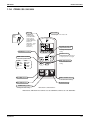
Branch Provider Unit BPMK928B42, B43 ............................................. 24
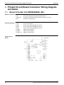
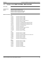
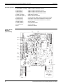
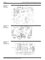
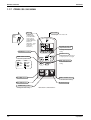
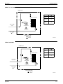
Outdoor Unit RMX140JVMB, RMX140JZVM ........................................ 25
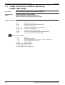
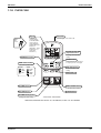
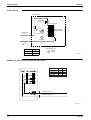
FTX25 / 35J Series, FTXD25 / 35K Series, FVX25 / 35K Series .......... 28
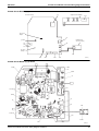
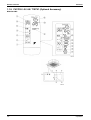
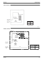
FTXD50~71JV Series............................................................................ 30
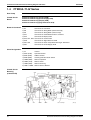
CDX25~60HAV Series, CDX25~60JV Series ....................................... 32
FLX25~60HV Series, FLX50 / 60JV Series........................................... 34
Main Functions Indoor Unit ............................................37
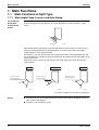
1. Main Functions......................................................................................38
1.1 Main Functions in Split Type ................................................................. 38
1.2 SkyAir .................................................................................................... 51
1.3 Cautions when SkyAir [Auto] [FAN] are used........................................ 53
Part 5
Main Functions Outdoor Unit / BP Unit...........................55
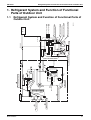
1. Refrigerant System and Function of Functional Parts of Outdoor Unit .57
1.1 Refrigerant System and Function of Functional Parts of Outdoor Unit......
57
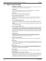
1.2 Major Functional Parts........................................................................... 58
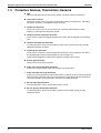
1.3 Protective Devices, Thermistors, Sensors............................................. 60
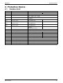
2. Protection Device ..................................................................................61
2.1 Outdoor Unit .......................................................................................... 61
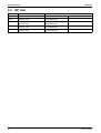
2.2 BP Unit .................................................................................................. 62
3. System control ......................................................................................63
3.1
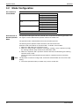
3.2
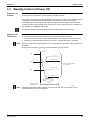
3.3
3.4
3.5
3.6
ii
Outline of System Control...................................................................... 63
Mode Configuration ............................................................................... 64
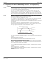
Standby Control at Power ON ............................................................... 65
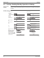
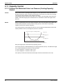
Cooling / Heating Standby Operation at Startup ................................... 66
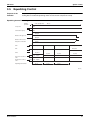
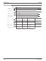
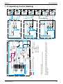
Equalizing Control ................................................................................. 67
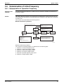
Determination of Initial Frequency......................................................... 69
Table of Contents
SiE18-201
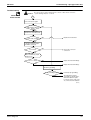
3.7
3.8
3.9
3.10
3.11
3.12
3.13
3.14
3.15
3.16
3.17
3.18
3.19
3.20
3.21
3.22
3.23
3.24
3.25
3.26
3.27
3.28
3.29
3.30
3.31
3.32
3.33
3.34
3.35
3.36
3.37
3.38
3.39
3.40
Part 6
Oil Return Operation.............................................................................. 74
Defrost Operation .................................................................................. 76
Pre-Equalization Standby Operation ..................................................... 77
Equalizing Control ................................................................................. 78
Capacity Control .................................................................................... 80
Peak Cut Control ................................................................................... 82
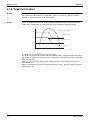
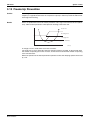
Freeze-Up Prevention ........................................................................... 83
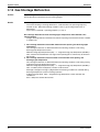
Gas Shortage Malfunction ..................................................................... 84
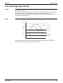
Discharge Pipe Control.......................................................................... 85
Input Current Control ............................................................................. 86
Wet Protection Control I ........................................................................ 89
Electric Parts Cooling and Electric Parts / Fin Temperature Control.........
90
Differential Pressure Control ................................................................. 91
Year-Round Cooling-Only Function....................................................... 92
Nighttime Low Noise Control ................................................................. 93
PI Control............................................................................................... 94
Warm-Up Function ................................................................................ 95
Compressor Protection Control ............................................................. 96
Fan Control............................................................................................ 97
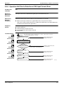
Motorized Valve Control of Outdoor Unit............................................... 99
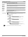
Cooling Outdoor Unit SC Control ........................................................ 105
BP Unit Motorized Valve Control ......................................................... 106
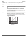
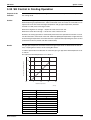
Gas Pipe Isothermal Control in Cooling Operation.............................. 109
SH Control in Cooling Operation ......................................................... 111
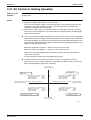
SC Control in Heating Operation ......................................................... 113
Heat Exchanger Isothermal Control in Heating Operation .................. 115
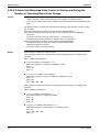
BP Unit Motorized Valve Control in High Discharge
Pipe Temperature................................................................................ 116
Inter-BP Units Heating Heat Exchanger Isothermal Control................ 117
Inter-BP Units Gas Pipe Isothermal Control ........................................ 118
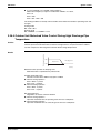
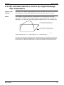
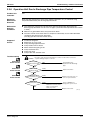
BP Unit Motorized Valve Control by Target Discharge
Pipe Temperature................................................................................ 119
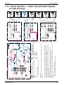
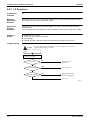
4-Way Valve Operation ....................................................................... 120
JIS Mode ............................................................................................. 121
Pump Down Operation ........................................................................ 122
Protection Control of SkyAir Indoor Units ............................................ 123
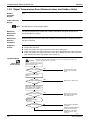
Flow of Refrigerant .......................................................125
1. Flow of Refrigerant..............................................................................126
1.1
1.2
1.3
1.4
1.5
1.6
1.7
1.8
1.9
1.10
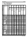
Flow of Refrigerant .............................................................................. 126
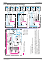
Standby Operation (Cooling) ............................................................... 127
Equalizing Control (Cooling)................................................................ 128
Oil Return Operation (Cooling) ............................................................ 129
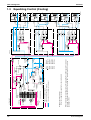
Low Outside Air Temperature Cooling ................................................ 130
All-Room Operation (Cooling) ............................................................. 131
Multi-Room Operation (No Surplus Refrigerant) (Cooling).................. 132
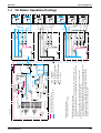
Multi-Room Operation (Cooling) (with Surplus Refrigerant) ................ 133
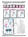
1-Room Operation — Indoor Unit with Large Capacity (Cooling)........ 134
1-Room Operation — Indoor Unit with Small Capacity
(2.5 kW) (Cooling) ............................................................................... 135
1.11 Standby Operation (Heating)............................................................... 136
Table of Contents
iii
SiE18-201
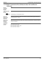
1.12
1.13
1.14
1.15
1.16
1.17
1.18
1.19
Part 7
Equalizing Control (Heating)................................................................ 137
Oil Return Operation (Heating)............................................................ 138
Defrost Operation ............................................................................... 139
All-Room Operation (Heating) ............................................................. 140
Multi-Room Operation (with non-Operating Room Unit) (Heating)...... 141
Multi-Room Operation (Heating).......................................................... 142
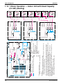
1-Room Operation — Indoor Unit with Large Capacity (Heating) ....... 143
1-Room Operation — Indoor Unit with Small Capacity
(2.5 kW) (Heating) ............................................................................... 144
Operations.....................................................................145
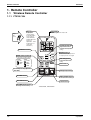
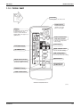
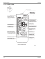
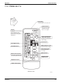
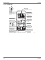
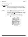
1. Remote Controller ...............................................................................146
1.1 Wireless Remote Controller................................................................. 146
1.2 Wired Remote Controller ..................................................................... 156
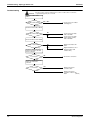
Part 8
Operating Test ..............................................................157
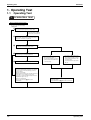
1. Operating Test ....................................................................................158
1.1
1.2
1.3
1.4
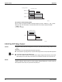
Operating Test..................................................................................... 158
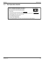
Test Operation Switch ......................................................................... 161
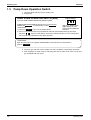
Pump Down Operation Switch............................................................. 162
Record of the Installation Position ....................................................... 163
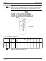
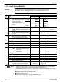
2. Method of Field Set .............................................................................164
2.1 Field Setting......................................................................................... 164
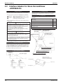
2.2 Interface Adaptor for Room Airconditioner <KRP928A1S>................. 172
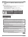
2.3 Precautions: For RMK140J / RMX140J Outdoor Unit Users............... 174
Part 9
Service Diagnosis .........................................................175
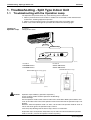
1. Troubleshooting - Split Type Indoor Unit.............................................176
1.1
1.2
1.3
1.4
1.5
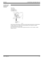
Troubleshooting with the Operation Lamp........................................... 176
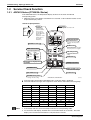
Service Check Function....................................................................... 178
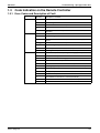
Code Indication on the Remote Controller .......................................... 179
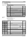
Troubleshooting................................................................................... 180
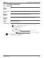
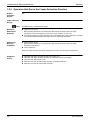
Troubleshooting Detail......................................................................... 181
2. Troubleshooting - SkyAir Indoor Unit ..................................................195
2.1
2.2
2.3
2.4
2.5
2.6
The INSPECTION/TEST Button.......................................................... 195
Self-Diagnosis by Wired Remote Controller ........................................ 196
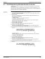
Fault Diagnosis by Wireless Remote Controller .................................. 197
Troubleshooting by LED on the Indoor Unit’s...................................... 199
Troubleshooting by Remote Controller Display / LED Display ............ 200
Troubleshooting Detail......................................................................... 201
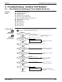
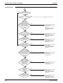
3. Troubleshooting - Outdoor Unit Related .............................................209
3.1
3.2
3.3
3.4
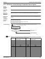
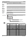
The Unit Runs but Doesn’t Cool (Heat) the Room .............................. 209
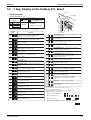
7 Seg. Display on the Outdoor P. C. Board......................................... 211
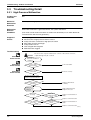
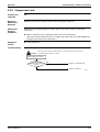
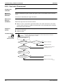
Troubleshooting Detail......................................................................... 212
How to Check ...................................................................................... 249
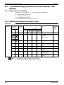
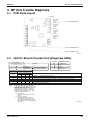
4. BP Unit Trouble Diagnosis ..................................................................259
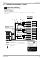
4.1 PCB Parts Layout ................................................................................ 259
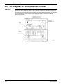
4.2 LED On Branch Provider Unit (Diagnosis LEDs)................................. 259
iv
Table of Contents
SiE18-201
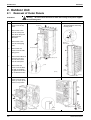
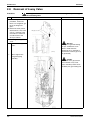
Part 10 Removal Procedure.......................................................261
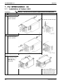
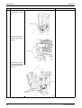
1. For BPMK928B42 · 43 ........................................................................262
1.1
1.2
1.3
1.4
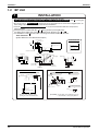
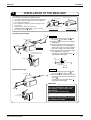
Installation of Indoor Unit..................................................................... 262
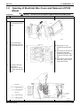
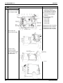
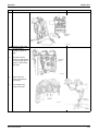
Opening of Electrical Box Cover and Removal of PCB Mount ............ 263
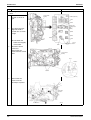
Removal of Motorized Valve................................................................ 265
Removal of Thermistor ........................................................................ 268
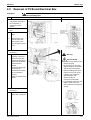
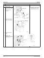
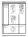
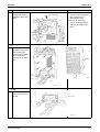
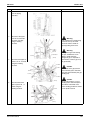
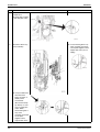
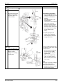
2. Outdoor Unit........................................................................................270
2.1
2.2
2.3
2.4
2.5
2.6
2.7
2.8
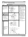
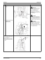
Removal of Outer Panels .................................................................... 270
Removal of PCB and Electrical Box .................................................... 271
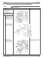
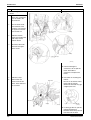
Removal of Propeller Fans and Fan Motors........................................ 279
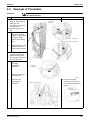
Removal of Thermistor ........................................................................ 281
Removal of Motorized Valve................................................................ 282
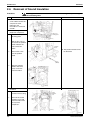
Removal of Sound Insulation............................................................... 284
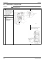
Removal of Compressor...................................................................... 286
Removal of 4-way Valve...................................................................... 288
3. Indoor Unit...........................................................................................292
3.1 Refer following table for indoor unit removal procedure ...................... 292
Part 11 Cautions before Operation............................................293
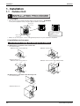
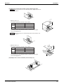
1. Installation ...........................................................................................294
1.1 Outdoor Unit ........................................................................................ 294
1.2 BP Unit ................................................................................................ 296
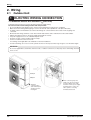
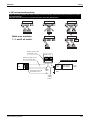
2. Wiring ..................................................................................................298
2.1 Outdoor Unit ........................................................................................ 298
2.2 BP Unit ................................................................................................ 300
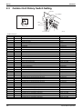
2.3 Outdoor Unit Rotary Switch Setting..................................................... 302
3. Others .................................................................................................304
3.1 Explanation for FTX25/35J Series....................................................... 304
3.2 Explanation for CDK(X)25~60H Series ............................................... 307
Part 12 Appendix .......................................................................309
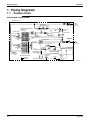
1. Piping Diagrams..................................................................................310
1.1 Outdoor Units ...................................................................................... 310
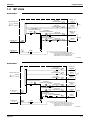
1.2 BP Units............................................................................................... 311
1.3 Indoor Units ......................................................................................... 312
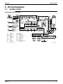
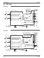
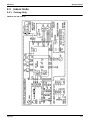
2. Wiring Diagrams..................................................................................317
2.1 Outdoor Units ...................................................................................... 317
2.2 BP Units............................................................................................... 318
2.3 Indoor Units ......................................................................................... 319
Index
............................................................................................i
Drawings & Flow Charts ................................................................ v
Table of Contents
v
SiE18-201
vi
Table of Contents
SiE18-201
Introduction
1. Introduction
1.1
Safety Cautions
Cautions and
Warnings
Be sure to read the following safety cautions before conducting repair work.
Warning” and “
Caution”. The “
Warning”
The caution items are classified into “
items are especially important since they can lead to death or serious injury if they are not
Caution” items can also lead to serious accidents under some
followed closely. The “
conditions if they are not followed. Therefore, be sure to observe all the safety caution items
described below.
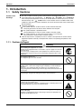
About the pictograms
This symbol indicates an item for which caution must be exercised.
The pictogram shows the item to which attention must be paid.
This symbol indicates a prohibited action.
The prohibited item or action is shown inside or near the symbol.
This symbol indicates an action that must be taken, or an instruction.
The instruction is shown inside or near the symbol.
After the repair work is complete, be sure to conduct a test operation to ensure that the
equipment operates normally, and explain the cautions for operating the product to the
customer.
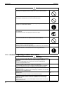
1.1.1 Cautions in Repair
Warning
Be sure to disconnect the power cable plug from the plug socket before
disassembling the equipment for a repair.
Working on the equipment that is connected to a power supply can cause an
electrical shook.
If it is necessary to supply power to the equipment to conduct the repair or
inspecting the circuits, do not touch any electrically charged sections of the
equipment.
If the refrigerant gas discharges during the repair work, do not touch the
discharging refrigerant gas.
The refrigerant gas can cause frostbite.
When disconnecting the suction or discharge pipe of the compressor at the
welded section, release the refrigerant gas completely at a well-ventilated
place first.
If there is a gas remaining inside the compressor, the refrigerant gas or
refrigerating machine oil discharges when the pipe is disconnected, and it can
cause injury.
If the refrigerant gas leaks during the repair work, ventilate the area. The
refrigerant gas can generate toxic gases when it contacts flames.
The step-up capacitor supplies high-voltage electricity to the electrical
components of the outdoor unit.
Be sure to discharge the capacitor completely before conducting repair work.
A charged capacitor can cause an electrical shock.
Do not start or stop the air conditioner operation by plugging or unplugging the
power cable plug.
Plugging or unplugging the power cable plug to operate the equipment can
cause an electrical shock or fire.
vii
Introduction
SiE18-201
Caution
Do not repair the electrical components with wet hands.
Working on the equipment with wet hands can cause an electrical shock.
Do not clean the air conditioner by splashing water.
Washing the unit with water can cause an electrical shock.
Be sure to provide the grounding when repairing the equipment in a humid or
wet place, to avoid electrical shocks.
Be sure to turn off the power switch and unplug the power cable when cleaning
the equipment.
The internal fan rotates at a high speed, and cause injury.
Do not tilt the unit when removing it.
The water inside the unit can spill and wet the furniture and floor.
Be sure to check that the refrigerating cycle section has cooled down
sufficiently before conducting repair work.
Working on the unit when the refrigerating cycle section is hot can cause burns.
Use the welder in a well-ventilated place.
Using the welder in an enclosed room can cause oxygen deficiency.
1.1.2 Cautions Regarding Products after Repair
Warning
Be sure to use parts listed in the service parts list of the applicable model and
appropriate tools to conduct repair work. Never attempt to modify the
equipment.
The use of inappropriate parts or tools can cause an electrical shock,
excessive heat generation or fire.
When relocating the equipment, make sure that the new installation site has
sufficient strength to withstand the weight of the equipment.
If the installation site does not have sufficient strength and if the installation
work is not conducted securely, the equipment can fall and cause injury.
Be sure to install the product correctly by using the provided standard
installation frame.
Incorrect use of the installation frame and improper installation can cause the
equipment to fall, resulting in injury.
Be sure to install the product securely in the installation frame mounted on a
window frame.
If the unit is not securely mounted, it can fall and cause injury.
Be sure to use an exclusive power circuit for the equipment, and follow the
technical standards related to the electrical equipment, the internal wiring
regulations and the instruction manual for installation when conducting
electrical work.
Insufficient power circuit capacity and improper electrical work can cause an
electrical shock or fire.
viii
For integral units
only
For integral units
only
SiE18-201
Introduction
Warning
Be sure to use the specified cable to connect between the indoor and outdoor
units. Make the connections securely and route the cable properly so that there
is no force pulling the cable at the connection terminals.
Improper connections can cause excessive heat generation or fire.
When connecting the cable between the indoor and outdoor units, make sure
that the terminal cover does not lift off or dismount because of the cable.
If the cover is not mounted properly, the terminal connection section can cause
an electrical shock, excessive heat generation or fire.
Do not damage or modify the power cable.
Damaged or modified power cable can cause an electrical shock or fire.
Placing heavy items on the power cable, and heating or pulling the power cable
can damage the cable.
Do not mix air or gas other than the specified refrigerant (R22) in the refrigerant
system.
If air enters the refrigerating system, an excessively high pressure results,
causing equipment damage and injury.
If the refrigerant gas leaks, be sure to locate the leak and repair it before
charging the refrigerant. After charging refrigerant, make sure that there is no
refrigerant leak.
If the leak cannot be located and the repair work must be stopped, be sure to
perform pump-down and close the service valve, to prevent the refrigerant gas
from leaking into the room. The refrigerant gas itself is harmless, but it can
generate toxic gases when it contacts flames, such as fan and other heaters,
stoves and ranges.
When replacing the coin battery in the remote controller, be sure to disposed
of the old battery to prevent children from swallowing it.
If a child swallows the coin battery, see a doctor immediately.
Caution
Installation of a leakage breaker is necessary in some cases depending on the
conditions of the installation site, to prevent electrical shocks.
Do not install the equipment in a place where there is a possibility of
combustible gas leaks.
If a combustible gas leaks and remains around the unit, it can cause a fire.
Be sure to install the packing and seal on the installation frame properly.
For integral units
If the packing and seal are not installed properly, water can enter the room and only
wet the furniture and floor.
1.1.3 Inspection after Repair
Warning
Check to make sure that the power cable plug is not dirty or loose, then insert
the plug into a power outlet all the way.
If the plug has dust or loose connection, it can cause an electrical shock or fire.
If the power cable and lead wires have scratches or deteriorated, be sure to
replace them.
Damaged cable and wires can cause an electrical shock, excessive heat
generation or fire.
Do not use a joined power cable or extension cable, or share the same power
outlet with other electrical appliances, since it can cause an electrical shock,
excessive heat generation or fire.
ix
Introduction
SiE18-201
Caution
Check to see if the parts and wires are mounted and connected properly, and
if the connections at the soldered or crimped terminals are secure.
Improper installation and connections can cause excessive heat generation,
fire or an electrical shock.
If the installation platform or frame has corroded, replace it.
Corroded installation platform or frame can cause the unit to fall, resulting in
injury.
Check the grounding, and repair it if the equipment is not properly grounded.
Improper grounding can cause an electrical shock.
Be sure to measure the insulation resistance after the repair, and make sure
that the resistance is 1 MΩ or higher.
Faulty insulation can cause an electrical shock.
Be sure to check the drainage of the indoor unit after the repair.
Faulty drainage can cause the water to enter the room and wet the furniture
and floor.
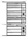
1.1.4 Using Icons
Icons are used to attract the attention of the reader to specific information. The meaning of each
icon is described in the table below:
1.1.5 Using Icons List
Icon
Type of
Information
Note
Description
Caution
A “caution” is used when there is danger that the reader, through
incorrect manipulation, may damage equipment, loose data, get
an unexpected result or has to restart (part of) a procedure.
Warning
A “warning” is used when there is danger of personal injury.
Reference
A “reference” guides the reader to other places in this binder or
in this manual, where he/she will find additional information on a
specific topic.
A “note” provides information that is not indispensable, but may
nevertheless be valuable to the reader, such as tips and tricks.
Note:
Caution
Warning
x
SiE18-201
Part 1
List of Function
1. List of Function........................................................................................2
1.1
1.2
1.3
1.4
List of Function
Function List for Europe R-22.................................................................. 2
Function List for Singapore, Malaysia, Indonesia.................................... 3
Function List for Australia ........................................................................ 4
Function List for Europe R-407C ............................................................. 5
1
List of Function
SiE18-201
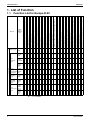
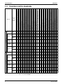
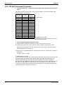
1. List of Function
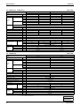
Function List for Europe R-22
Indoor
Unit /
Outdoor
Unit
Inverter (with Inverter Power Control)
PAM control (Pulse Amplitude Modulation Control)
Horizontal Scroll, Oval Scroll Compressor (DAIKIN SCROLL)
Reluctance DC Motor
Dual Flaps
Power-Airflow Dual Flaps
Power-Airflow Diffuser
Wide-Angle Louvers
Vertical Auto-Swing (Up and Down)
Horizontal Auto-Swing (Right and Left)
3-D Airflow
Auto Fan Speed
Silent Operation Control (Automatic)
Intelligent Eye
Automatic Operation
Programme Dry Function
Fan Only
Inverter Powerful Operation
Home Leave Operation
Indoor Unit On/Off Switch
Air-Purifying Filter
with Bacteriostatic, Virustatic & Deodorizing Functions
Mold-Proof Air Filter
Washable Grille
Filter Cleaning Indicator
Good-Sleep Cooling Operation
72-Hour On/Off Timer
24-Hour On/Off Timer
Night Set Mode
Auto-Restart (after Power Failure)
Self-Diagnosis Digital Display
Self-Diagnosis LED Display
Wiring-Error Check
Anticorrosion Treatment of Outdoor Heat Exchanger
Multi-Split/Split Type Compatible Indoor Unit
High-Ceiling Application
Chargeless
Wireless (FHYC: Option)
Wired (FHYC, FDYM: Option)
Group Control by 1 Remote Controller
1.1
RMX
140J
– – – – – – – – – – – – – – –
–
– – – – – – – – – – – 115 – – –
m
FTX25/
35JA
– – – – – – – – – – – – – – – – – –
FTXD
25/35KZ – – – – – – – – – – – – – – – – – –
FTXD
50/60/
71J
– – – – – – – – – – – – – – –
Floor/
Ceiling
Suspended
Dual Type
FLX25/
35H
FLX50/
60J
– – – – – – – – – – – – – – –
– 2
Floor
Standing
Type
FVX25/
35KZ
– – – – – – – – – – – – – – – – – – – –
Ceiling
Mounted
Cassette
Type
FHYC
35/50/
60/71
B7
– – – – – – – – – – – – – – –
–
– – – – – – – CDX
25/35/
50/60
HA (J)
– – – – – – – – – – – – – – –
– – – – – – – – – – – –
FHYB
35/45/
60/71
FK7
– – – – – – – – – – – – – – – – –
–
– – – – – – – – – – Division
Outdoor Unit
Heat Pump
Indoor Unit
Wall
Mounted
Type
Duct
Connected
Type
1
1
– – – –
1 : for FLX50/60J
2 – : for FLX50/60J
2
List of Function
Cooling Only
Indoor Unit
1.2
Division
Outdoor Unit
Wall
Mounted
Type
Floor/
Ceiling
Suspended
Dual Type
Ceiling
Mounted
Cassette
Type
Duct
Connected
Type
List of Function
Indoor
Unit /
Outdoor
Unit
Inverter (with Inverter Power Control)
PAM control (Pulse Amplitude Modulation Control)
Horizontal Scroll, Oval Scroll Compressor (DAIKIN SCROLL)
Reluctance DC Motor
Dual Flaps
Power-Airflow Dual Flaps
Power-Airflow Diffuser
Wide-Angle Louvers
Vertical Auto-Swing (Up and Down)
Horizontal Auto-Swing (Right and Left)
3-D Airflow
Auto Fan Speed
Silent Operation Control (Automatic)
Intelligent Eye
Automatic Operation
Programme Dry Function
Fan Only
Inverter Powerful Operation
Home Leave Operation
Indoor Unit On/Off Switch
Air-Purifying Filter
with Bacteriostatic, Virustatic & Deodorizing Functions
Mold-Proof Air Filter
Washable Grille
Filter Cleaning Indicator
Good-Sleep Cooling Operation
72-Hour On/Off Timer
24-Hour On/Off Timer
Night Set Mode
Auto-Restart (after Power Failure)
Self-Diagnosis Digital Display
Self-Diagnosis LED Display
Wiring-Error Check
Anticorrosion Treatment of Outdoor Heat Exchanger
Multi-Split/Split Type Compatible Indoor Unit
High-Ceiling Application
Chargeless
Wireless (FHYC, FDYM: Option)
Wired (FHYC, FDYM: Option)
Group Control by 1 Remote Controller
SiE18-201
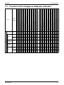
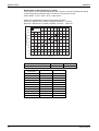
List of Function
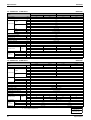
Function List for Singapore, Malaysia, Indonesia
RMK
140JA
– – – – – – – – – – – – – –
–
– – – – – – – – – – – – – – –
FTK25/
35J
– – – – – – – – – – – – – – – – – –
FTKD
50/60/
71J
– – – – – – – – – – – – – – –
FLK25/
35/50/
60H
– – – – – – – – – – – – – – – – –
FHYC
35/50/
60/71K
– – – – – – – – – – – – – – – –
–
– – – – – – – CDK25/
35/50/
– – – – – – – – – – – – – – 60HA
–
– – – – – – – – – – – –
FDYM
60/03FA – – – – – – – – – – – – – – – – – –
–
– – – – – – – – – 1
– – – –
3
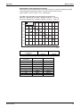
List of Function
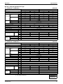
Function List for Australia
Division
Outdoor Unit
Cooling Only
Indoor Unit
Wall
Mounted
Type
Floor/
Ceiling
Suspended
Dual Type
Ceiling
Mounted
Cassette
Type
Duct
Connected
Type
Outdoor Unit
Heat Pump
Indoor Unit
Wall
Mounted
Type
Floor/
Ceiling
Suspended
Dual Type
Ceiling
Mounted
Cassette
Type
Duct
Connected
Type
Indoor
Unit /
Outdoor
Unit
Inverter (with Inverter Power Control)
PAM control (Pulse Amplitude Modulation Control)
Horizontal Scroll, Oval Scroll Compressor (DAIKIN SCROLL)
Reluctance DC Motor
Dual Flaps
Power-Airflow Dual Flaps
Power-Airflow Diffuser
Wide-Angle Louvers
Vertical Auto-Swing (Up and Down)
Horizontal Auto-Swing (Right and Left)
3-D Airflow
Auto Fan Speed
Silent Operation Control (Automatic)
Intelligent Eye
Automatic Operation
Programme Dry Function
Fan Only
Inverter Powerful Operation
Home Leave Operation
Indoor Unit On/Off Switch
Air-Purifying Filter
with Bacteriostatic, Virustatic & Deodorizing Functions
Mold-Proof Air Filter
Washable Grille
Filter Cleaning Indicator
Good-Sleep Cooling Operation
72-Hour On/Off Timer
24-Hour On/Off Timer
Night Set Mode
Auto-Restart (after Power Failure)
Self-Diagnosis Digital Display
Self-Diagnosis LED Display
Wiring-Error Check
Anticorrosion Treatment of Outdoor Heat Exchanger
Multi-Split/Split Type Compatible Indoor Unit
High-Ceiling Application
Chargeless
Wireless (FHYC, FDYM: Option)
Wired (FHYC, FDYM: Option)
Group Control by 1 Remote Controller
1.3
SiE18-201
RMK
140J
– – – – – – – – – – – – – –
–
– – – – – – – – – – – 115
m – – –
FTK25/
35J
– – – – – – – – – – – – – – – – – –
FTKD
50/60/
71J
– – – – – – – – – – – – – – –
FLK25/
35H
50/60J
– – – – – – – – – – – – – – –
– 2
FHYC
35/50/
60/71K
– – – – – – – – – – – – – – – –
–
– – – – – – – CDK25/
35/50/
– – – – – – – – – – – – – – 60HA
–
– – – – – – – – – – – –
FDYM
60/03FA – – – – – – – – – – – – – – – – – –
–
– – – – – – – – – RMX
140J
– – – – – – – – – – – – – – –
–
– – – – – – – – – – – 115
m – – –
FTX25/
35J
– – – – – – – – – – – – – – – – – –
FTXD
50/60/
71J
– – – – – – – – – – – – – – –
FLX25/
35H
50/60J
– – – – – – – – – – – – – – –
– 2
FHYC
35/50/
60/71K
– – – – – – – – – – – – – – –
–
– – – – – – – CDX25/
35/50/
– – – – – – – – – – – – – – 60HA
–
– – – – – – – – – – – –
FDYM
60/03FA – – – – – – – – – – – – – – – – –
–
– – – – – – – – – 1
1
1
1
– – – –
– – – –
1 : for FLK, FLX50/60J
2 – : for FLK, FLX50/60J
4
List of Function
SiE18-201
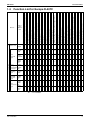
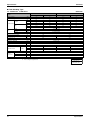
Function List for Europe R-407C
Indoor
Unit /
Outdoor
Unit
Inverter (with Inverter Power Control)
PAM control (Pulse Amplitude Modulation Control)
Horizontal Scroll, Oval Scroll Compressor (DAIKIN SCROLL)
Reluctance DC Motor
Dual Flaps
Power-Airflow Dual Flaps
Power-Airflow Diffuser
Wide-Angle Louvers
Vertical Auto-Swing (Up and Down)
Horizontal Auto-Swing (Right and Left)
3-D Airflow
Auto Fan Speed
Silent Operation Control (Automatic)
Intelligent Eye
Automatic Operation
Programme Dry Function
Fan Only
Inverter Powerful Operation
Home Leave Operation
Indoor Unit On/Off Switch
Air-Purifying Filter
with Bacteriostatic, Virustatic & Deodorizing Functions
Mold-Proof Air Filter
Washable Grille
Filter Cleaning Indicator
Good-Sleep Cooling Operation
72-Hour On/Off Timer
24-Hour On/Off Timer
Night Set Mode
Auto-Restart (after Power Failure)
Self-Diagnosis Digital Display
Self-Diagnosis LED Display
Wiring-Error Check
Anticorrosion Treatment of Outdoor Heat Exchanger
Multi-Split/Split Type Compatible Indoor Unit
High-Ceiling Application
Chargeless
Wireless (FHYC: Option)
Wired (FHYC, FDYM: Option)
Group Control by 1 Remote Controller
1.4
RMX
140JZ
– – – – – – – – – – – – – – –
–
– – – – – – – – – – – 115
m – – –
FTX25/
35JA
– – – – – – – – – – – – – – – – – –
FTXD
25/35KZ – – – – – – – – – – – – – – – – – –
FTXD
50/60/
71J
– – – – – – – – – – – – – – –
Floor/
Ceiling
Suspended
Dual Type
FLX25/
35H
FLX50/
60J
– – – – – – – – – – – – – – –
– 2
Floor
Standing
Type
FVX25/
35KZ
– – – – – – – – – – – – – – – – – – – –
Ceiling
Mounted
Cassette
Type
FHYC
35/50/
60/71
B7
– – – – – – – – – – – – – – –
–
– – – – – – – CDX
25/35/
50/60
HA
– – – – – – – – – – – – – – –
– – – – – – – – – – – –
FHYB
35/45/
60/71
FK7
– – – – – – – – – – – – – – – – –
–
– – – – – – – – – – Division
Outdoor Unit
Wall
Mounted
Type
Heat Pump
Indoor Unit
List of Function
Duct
Connected
Type
1
1
– – – –
1 : for FLX50/60J
2 – : for FLX50/60J
List of Function
5
List of Function
6
SiE18-201
List of Function
SiE18-201
Part 2
Specifications
1. Specifications ..........................................................................................8
1.1 Outdoor Units .......................................................................................... 8
1.2 BP Units................................................................................................. 16
1.3 Indoor Units (for Europe) ....................................................................... 17
Specifications
7
Specifications
SiE18-201
1. Specifications
1.1
Outdoor Units
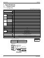
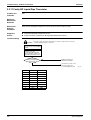
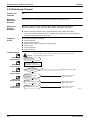
1.1.1 Cooling Only
50Hz 220-240V / 60Hz 220-230V
Model
RMK140JVMC9 (8)
kW
14.5
kcal/h
12,470
Power Consumption ★
W
5,000
Running Current ★
A
Cooling Capacity (19.0˚CWB)
23.2
Casing Color
Ivory White
Type
Compressor
Hermetically Sealed Scroll Type (Oval Discharge)
Model
JT100FBVD
Motor Output
Refrigerant
Oil
Refrigerant
W
3,300
Model
SUNISO 4GSD.I.
Charge
kg
1.5
Type
R22
Charge
m³/min
Air Flow Rate
cfm
kg
9.9
H
114
L
104
H
4,024
L
3,671
Type
Fan
Propeller
Motor Output
W
(Upper Side) H : 53 L : 38
(Lower Side) H : 41 L : 30
Running Current
A
(Upper Side) H : 0.50 L : 0.45
(Lower Side) H : 0.47 L : 0.42
Power Consumption
W
(Upper Side) H : 93.1 L : 78.8
Power Factor
%
Starting Current
(Lower Side) H : 81.3 L : 68.8
100
A
29.0
Dimensions (H×W×D)
mm
1,345×880×320
Package Dimensions
mm
918×394×1,397
Weight
kg
134
Gross Weight
kg
143
Operation Sound
Piping
Connection
dBA
53
Liquid
mm
φ 9.5 (Flare Connection)
Gas
mm
φ19.1 (Flare Connection)
Drain
mm
φ18
Heat Insulation
Both Liquid and Gas Pipes
No. of Wiring Connection
3 for Power Supply, 4 for Interunit Wiring (Including Earth Wiring)
115 (Total Main Piping and Branch Piping)
55 (Total Main Piping), 60 (Total Branch Piping)
15 (Max. Length for Each Room)
Max. Interunit Piping Length
m
Amount of Additional Charge
g/m
Chargeless
m
30 (Between Indoor or BP Unit and Outdoor Unit), 15 (Between Indoor or BP Units)
Max. Installation Height Difference
Drawing No.
3D030948A
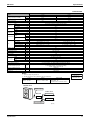
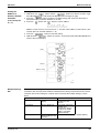
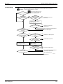
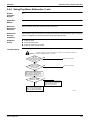
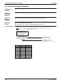
Notes:
1. ★ Refer to Engineering Data Book.
2. The data are based on the conditions shown in the table below.
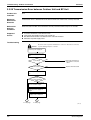
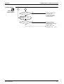
Cooling
Piping Length
Indoor ; 27˚CDB / 19.0˚CWB
Outdoor ; 35˚CDB
Conversion Formulae
kcal/h=kW×860
Btu/h=kW×3414
cfm=m³/min×35.3
Main Piping : 5m
Branch Piping : 3m
(each indoor unit / 71 Class+60 Class)
Outdoor Unit
Main Piping
Indoor Unit
BP Unit
Branch Piping
(Q0143)
8
Specifications
SiE18-201
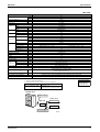
Specifications
60Hz 220V
Model
RMK140JVMT9
kW
14.5
kcal/h
12,500
Power Consumption ★
W
4,950
Running Current ★
A
Cooling Capacity (19.5˚CWB)
23.0
Casing Color
Ivory White
Type
Compressor
Hermetically Sealed Scroll Type (Oval Discharge)
Model
JT100FBVD
Motor Output
Refrigerant
Oil
Refrigerant
W
3,300
Model
SUNISO 4GSD.I.
Charge
kg
1.5
Type
R22
Charge
m³/min
Air Flow Rate
cfm
kg
9.9
H
114
L
104
H
4,024
L
3,671
Type
Fan
Propeller
Motor Output
W
(Upper Side) H : 53 L : 38
(Lower Side) H : 41 L : 30
Running Current
A
(Upper Side) H : 0.50 L : 0.45
(Lower Side) H : 0.47 L : 0.42
Power Consumption
W
(Upper Side) H : 93.1 L : 78.8
Power Factor
%
Starting Current
(Lower Side) H : 81.3 L : 68.8
100
A
29.0
Dimensions (H×W×D)
mm
1,345×880×320
Package Dimensions
mm
918×394×1,397
Weight
kg
134
Gross Weight
kg
143
Operation Sound
Piping
Connection
dBA
53
Liquid
mm
φ 9.5 (Flare Connection)
Gas
mm
φ19.1 (Flare Connection)
Drain
mm
φ18
Heat Insulation
Both Liquid and Gas Pipes
No. of Wiring Connection
3 for Power Supply, 4 for Interunit Wiring (Including Earth Wiring)
115 (Total Main Piping and Branch Piping)
55 (Total Main Piping), 60 (Total Branch Piping)
15 (Max. Length for Each Room)
Max. Interunit Piping Length
m
Amount of Additional Charge
g/m
Chargeless
m
30 (Between Indoor or BP Unit and Outdoor Unit), 15 (Between Indoor or BP Units)
Max. Installation Height Difference
Drawing No.
3D030949A
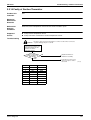
Notes:
1. ★ Refer to Engineering Data Book.
2. The data are based on the conditions shown in the table below.
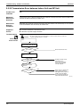
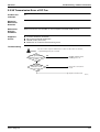
Cooling
Piping Length
Indoor ; 27˚CDB / 19.5˚CWB
Outdoor ; 35˚CDB
Conversion Formulae
kcal/h=kW×860
Btu/h=kW×3414
cfm=m³/min×35.3
Main Piping : 5m
Branch Piping : 3m
(each indoor unit / 71 Class+60 Class)
Outdoor Unit
Main Piping
Indoor Unit
BP Unit
Branch Piping
(Q0143)
Specifications
9
Specifications
SiE18-201
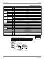
50Hz 220-230-240V / 60Hz 220-230V
Model
RMK140JAVM
kW
14.5
kcal/h
12,470
Power Consumption ★
W
4,650
Running Current ★
A
Cooling Capacity (19.0˚CWB)
20.4
Casing Color
Ivory White
Type
Compressor
Hermetically Sealed Scroll Type (Oval Discharge)
Model
JT100FBVD
Motor Output
Refrigerant
Oil
Refrigerant
W
3,300
Model
SUNISO 4GSD.I.
Charge
kg
1.5
Type
R22
Charge
m³/min
Air Flow Rate
cfm
kg
4.5
H
114
L
104
H
4,024
L
3,671
Type
Fan
Propeller
Motor Output
W
(Upper Side) H : 53 L : 38
(Lower Side) H : 41 L : 30
Running Current
A
(Upper Side) H : 0.50 L : 0.45
(Lower Side) H : 0.47 L : 0.42
Power Consumption
W
(Upper Side) H : 93.1 L : 78.8
Power Factor
%
Starting Current
(Lower Side) H : 81.3 L : 68.8
100
A
29.0
Dimensions (H×W×D)
mm
1,345×880×320
Package Dimensions (W×D×H)
mm
918×394×1,397
Weight
kg
111
Gross Weight
kg
120
Operation Sound
Piping
Connection
dBA
50
Liquid
mm
φ9.5 (Flare Connection)
Gas
mm
φ19.1 (Flare Connection)
Drain
mm
φ18
Heat Insulation
Both Liquid and Gas Pipes
No. of Wiring Connection
3 For Power Supply, 4 For Interunit Wiring
Max. Interunit Piping Length
m
110 (Total Main Piping and Branch PIping)
30 (Total Main Piping), 60 (Total Branch Piping)
20 (Max. Length for Each Room)
Amount of Additional Charge
g/m
Additional refrigerant to be charge : R (kg)
R= (Total length of the liquid pipe-line of φ9.5) ×0.05 + (Total length of the liquid pipe-line of φ6.4) × 0.025
∗If the value of “R” is less than 0.5, additional charging of refrigerant is unnecessary.
m
15 (Between Indoor or BP Unit and Outdoor Unit), 10 (Both between Indoor Units and BP Units)
Max. Installation Height Difference
Drawing No.
3D033202
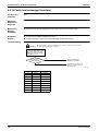
Notes:
1. ★ Refer to Engineering Data Book.
2. The data are based on the conditions shows in the table below.
Cooling
Piping Length
Indoor ; 27˚CDB / 19.0˚CWB
Outdoor ; 35˚CDB
Conversion Formulae
kcal/h=kW×860
Btu/h=kW×3414
cfm=m³/min×35.3
Main Piping : 5m
Branch Piping : 3m (each indoor unit / 71 Class+60 Class)
Outdoor Unit
Main Piping
Indoor Unit
BP Unit
Branch Piping
(Q0143)
10
Specifications
SiE18-201
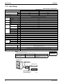
Specifications
50Hz 220-230-240V / 60Hz 220-230V
Model
RMK140JZVMA
Cooling Capacity (19.0˚CWB)
kW
14.5
kcal/h
12,470
Power Consumption ★
W
5,000
Running Current ★
A
23.2-22.2-21.3
Casing Color
Ivory White
Type
Compressor
Hermetically Sealed Scroll Type (Oval Discharge)
Model
JT100FAVD
Motor Output
Refrigerant
Oil
Refrigerant
W
3,300
Model
DAPHNE FVC68D
Charge
kg
1.5
Type
R407C
Charge
m³/min
Air Flow Rate
cfm
kg
9.9
H
114
L
104
H
4,024
L
3,671
Type
Fan
Propeller
Motor Output
W
(Upper Side) H : 53 L : 38
(Lower Side) H : 41 L : 30
Running Current
A
(Upper Side) H : 0.50 L : 0.45
(Lower Side) H : 0.47 L : 0.42
Power Consumption
W
(Upper Side) H : 93.1 L : 78.8
Power Factor
%
Starting Current
(Lower Side) H : 81.3 L : 68.8
100
A
29.0
Dimensions (H×W×D)
mm
1,345×880×320
Package Dimensions (W×D×H)
mm
918×394×1,397
Weight
kg
134
Gross Weight
kg
143
Operation Sound
Piping
Connection
dBA
53
Liquid
mm
φ9.5 (Flare Connection)
Gas
mm
φ19.1 (Flare Connection)
Drain
mm
φ18
Heat Insulation
Both Liquid and Gas Pipes
No. of Wiring Connection
3 For Power Supply, 4 For Interunit Wiring (Included Earth Wiring)
115 (Total Main Piping and Branch PIping)
55 (Total Main Piping), 60 (Total Branch Piping)
15 (Max. Length for Each Room)
Max. Interunit Piping Length
m
Amount of Additional Charge
g/m
Chargeless
m
30 (Between Indoor or BP Unit and Outdoor Unit), 15 (Both between Indoor Units and BP Units)
Max. Installation Height Difference
Drawing No.
3D031579
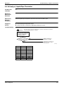
Notes:
1. ★ Refer to Engineering Data Book.
2. The data are based on the conditions shows in the table below.
Cooling
Piping Length
Indoor ; 27˚CDB / 19.0˚CWB
Outdoor ; 35˚CDB
Conversion Formulae
kcal/h=kW×860
Btu/h=kW×3414
cfm=m³/min×35.3
Main Piping : 5m
Branch Piping : 3m (each indoor unit / 71 Class+60 Class)
Outdoor Unit
Main Piping
Indoor Unit
BP Unit
Branch Piping
(Q0143)
Specifications
11
Specifications
SiE18-201
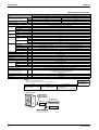
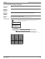
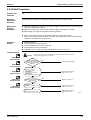
1.1.2 Heat Pump
50Hz 220-240V / 60Hz 220-230V
RMX140JVMC9 (8)
Model
Cooling
Heating
kW
14.5
16.5
kcal/h
12,470
14,190
Power Consumption ★
W
5,000
5,780
Running Current ★
A
23.2
Cooling Capacity (19.0˚CWB)
26.8
Casing Color
Ivory White
Type
Compressor
Hermetically Sealed Scroll Type (Oval Discharge)
Model
JT100FBVD
Motor Output
Refrigerant
Oil
Refrigerant
W
3,300
Model
SUNISO 4GSD.I.
Charge
L
1.5
Type
R22
Charge
m³/min
Air Flow Rate
cfm
kg
9.9
H
114
L
104
H
4,024
L
3,671
Type
Fan
Propeller
Motor Output
W
(Upper Side) H : 53 L : 38
(Lower Side) H : 41 L : 30
Running Current
A
(Upper Side) H : 0.50 L : 0.45
(Lower Side) H : 0.47 L : 0.42
Power Consumption
W
(Upper Side) H : 93.1 L : 78.8
Power Factor
%
Starting Current
(Lower Side) H : 81.3 L : 68.8
100
A
29.0
Dimensions (H×W×D)
mm
1,345×880×320
Package Dimensions
mm
918×394×1,397
Weight
kg
136
Gross Weight
kg
145
Operation Sound
Piping
Connection
dBA
53
Liquid
mm
φ 9.5 (Flare Connection)
Gas
mm
φ19.1 (Flare Connection)
Drain
mm
φ18
Heat Insulation
Both Liquid and Gas Pipes
No. of Wiring Connection
3 for Power Supply, 4 for Interunit Wiring (Including Earth Wiring)
115 (Total Main Piping and Branch Piping)
55 (Total Main Piping), 60 (Total Branch Piping)
15 (Max. Length for Each Room)
Max. Interunit Piping Length
m
Amount of Additional Charge
g/m
Chargeless
m
30 (Between Indoor or BP Unit and Outdoor Unit), 15 (Between Indoor or BP Units)
Max. Installation Height Difference
Drawing No.
3D030946A
Notes:
Conversion Formulae
1. ★ Refer to Engineering Data Book.
2. The data are based on the conditions shown in the table below.
Cooling
Heating
Indoor ; 27˚CDB / 19.0˚CWB
Outdoor ; 35˚CDB
Piping Length
Indoor ; 21˚CDB
Outdoor ; 7˚CDB / 6˚CWB
kcal/h=kW×860
Btu/h=kW×3414
cfm=m³/min×35.3
Main Piping : 5m
Branch Piping : 3m
(each indoor unit / 71 Class+60 Class)
Outdoor Unit
Main Piping
Indoor Unit
BP Unit
Branch Piping
(Q0143)
12
Specifications
SiE18-201
Specifications
60Hz 220-230V
RMX140JVMT9
Model
Cooling
Heating
kW
14.5
16.5
kcal/h
12,500
14,200
Power Consumption ★
W
4,950
5,870
Running Current ★
A
23.0
Cooling Capacity (19.5˚CWB)
27.2
Casing Color
Ivory White
Type
Compressor
Hermetically Sealed Scroll Type (Oval Discharge)
Model
JT100FBVD
Motor Output
Refrigerant
Oil
Refrigerant
W
3,300
Model
SUNISO 4GSD.I.
Charge
L
1.5
Type
R22
Charge
m³/min
Air Flow Rate
cfm
kg
9.9
H
114
L
104
H
4,024
L
3,671
Type
Fan
Propeller
Motor Output
W
(Upper Side) H : 53 L : 38
(Lower Side) H : 41 L : 30
Running Current
A
(Upper Side) H : 0.50 L : 0.45
(Lower Side) H : 0.47 L : 0.42
Power Consumption
W
(Upper Side) H : 93.1 L : 78.8
Power Factor
%
Starting Current
(Lower Side) H : 81.3 L : 68.8
100
A
29.0
Dimensions (H×W×D)
mm
1,345×880×320
Package Dimensions
mm
918×394×1,397
Weight
kg
136
Gross Weight
kg
145
Operation Sound
Piping
Connection
dBA
53
Liquid
mm
φ9.5 (Flare Connection)
Gas
mm
φ19.1 (Flare Connection)
Drain
mm
φ18
Heat Insulation
Both Liquid and Gas Pipes
No. of Wiring Connection
3 for Power Supply, 4 for Interunit Wiring (Including Earth Wiring)
115 (Total Main Piping and Branch Piping)
55 (Total Main Piping), 60 (Total Branch Piping)
15 (Max. Length for Each Room)
Max. Interunit Piping Length
m
Amount of Additional Charge
g/m
Chargeless
m
30 (Between Indoor or BP Unit and Outdoor Unit), 15 (Between Indoor or BP Units)
Max. Installation Height Difference
Drawing No.
3D030947A
Notes:
Conversion Formulae
1. ★ Refer to Engineering Data Book.
2. The data are based on the conditions shown in the table below.
Cooling
Heating
Indoor ; 27˚CDB / 19.5˚CWB
Outdoor ; 35˚CDB
Piping Length
Indoor ; 21˚CDB
Outdoor ; 7˚CDB / 6˚CWB
kcal/h=kW×860
Btu/h=kW×3414
cfm=m³/min×35.3
Main Piping : 5m
Branch Piping : 3m
(each indoor unit / 71 Class+60 Class)
Outdoor Unit
Main Piping
Indoor Unit
BP Unit
Branch Piping
(Q0143)
Specifications
13
Specifications
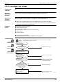
SiE18-201
50Hz 220-240V / 60Hz 220-230V
RMX140JVMB
Model
Cooling
Heating
kW
14.5
16.5
kcal/h
12,470
14,190
Power Consumption ★
W
5,000
5,780
Running Current ★
A
23.2
Cooling Capacity (19.0˚CWB)
26.8
Casing Color
Ivory White
Type
Compressor
Hermetically Sealed Scroll Type (Oval Discharge)
Model
JT100FBVD
Motor Output
Refrigerant
Oil
Refrigerant
W
3,300
Model
SUNISO 4GSD.I.
Charge
L
1.5
Type
R22
Charge
m³/min
Air Flow Rate
cfm
kg
9.9
H
114
L
104
H
4,024
L
3,671
Type
Fan
Propeller
Motor Output
W
(Upper Side) H : 53 L : 38
(Lower Side) H : 41 L : 30
Running Current
A
(Upper Side) H : 0.50 L : 0.45
(Lower Side) H : 0.47 L : 0.42
Power Consumption
W
(Upper Side) H : 93.1 L : 78.8
Power Factor
%
Starting Current
(Lower Side) H : 81.3 L : 68.8
100
A
29.0
Dimensions (H×W×D)
mm
1,345×880×320
Package Dimensions (W×D×H)
mm
918×394×1,397
Weight
kg
136
Gross Weight
kg
145
Operation Sound
Piping
Connection
dBA
53
Liquid
mm
φ9.5 (Flare Connection)
Gas
mm
φ19.1 (Flare Connection)
Drain
mm
φ18
Heat Insulation
Both Liquid and Gas Pipes
No. of Wiring Connection
3 For Power Supply, 4 For Interunit Wiring (Included Earth Wiring)
115 (Total Main Piping and Branch PIping)
55 (Total Main Piping), 60 (Total Branch Piping)
15 (Max. Length for Each Room)
Max. Interunit Piping Length
m
Amount of Additional Charge
g/m
Chargeless
m
30 (Between Indoor or BP Unit and Outdoor Unit), 15 (Both between Indoor Units and BP Units)
Max. Installation Height Difference
Drawing No.
3D030950A
Notes:
Conversion Formulae
1. ★ Refer to Engineering Data Book.
2. The data are based on the conditions shown in the table below.
Cooling
Heating
Indoor ; 27˚CDB / 19.0˚CWB
Outdoor ; 35˚CDB
Indoor ; 20˚CDB
Outdoor ; 7˚CDB / 6˚CWB
Piping Length
kcal/h=kW×860
Btu/h=kW×3414
cfm=m³/min×35.3
Main Piping : 5m
Branch Piping : 3m
(each indoor unit / 71 Class+60 Class)
Outdoor Unit
Main Piping
Indoor Unit
BP Unit
Branch Piping
(Q0143)
14
Specifications
SiE18-201
Specifications
50Hz 220-230-240V / 60Hz 220-230V
RMX140JZVMB
Model
Cooling
Cooling Capacity (19.0˚CWB)
Heating
kW
14.5
16.5
kcal/h
12,470
14,190
Power Consumption ★
W
5,000
6,050
Running Current ★
A
23.2-22.2-21.3
28.1-26.8-25.7
Casing Color
Ivory White
Type
Compressor
Hermetically Sealed Scroll Type (Oval Discharge)
Model
JT100FAVD
Motor Output
Refrigerant
Oil
Refrigerant
W
3,300
Model
DAPHNE FVC68D
Charge
L
1.5
Type
R407C
Charge
m³/min
Air Flow Rate
cfm
kg
9.9
H
114
L
104
H
4,024
L
3,671
Type
Fan
Propeller
Motor Output
W
(Upper Side) H : 53 L : 38
(Lower Side) H : 41 L : 30
Running Current
A
(Upper Side) H : 0.50 L : 0.45
(Lower Side) H : 0.47 L : 0.42
Power Consumption
W
(Upper Side) H : 93.1 L : 78.8
Power Factor
%
Starting Current
(Lower Side) H : 81.3 L : 68.8
100
A
29.0
Dimensions (H×W×D)
mm
1,345×880×320
Package Dimensions (W×D×H)
mm
918×394×1,397
Weight
kg
136
Gross Weight
kg
145
Operation Sound
Piping
Connection
dBA
53
Liquid
mm
φ9.5 (Flare Connection)
Gas
mm
φ19.1 (Flare Connection)
Drain
mm
φ18
Heat Insulation
Both Liquid and Gas Pipes
No. of Wiring Connection
3 For Power Supply, 4 For Interunit Wiring (Included Earth Wiring)
115 (Total Main Piping and Branch Piping)
55 (Total Main Piping), 60 (Total Branch Piping)
15 (Max. Length for Each Room)
Max. Interunit Piping Length
m
Amount of Additional Charge
g/m
Chargeless
m
30 (Between Indoor or BP Unit and Outdoor Unit), 15 (Both between Indoor Units and BP Units)
Max. Installation Height Difference
Drawing No.
3D031578
Notes:
Conversion Formulae
1. ★ Refer to Engineering Data Book.
2. The data are based on the conditions shows in the table below.
Cooling
Heating
Indoor ; 27˚CDB / 19.0˚CWB
Outdoor ; 35˚CDB
Indoor ; 21˚CDB
Outdoor ; 7˚CDB / 6˚CWB
Piping Length
kcal/h=kW×860
Btu/h=kW×3414
cfm=m³/min×35.3
Main Piping : 5m
Branch Piping : 3m
(each indoor unit / 71 Class+60
Class)
Outdoor Unit
Main Piping
Indoor Unit
BP Unit
Branch Piping
(Q0143)
Specifications
15
Specifications
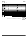
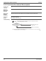
1.2
SiE18-201
BP Units
50Hz 220-240V / 60Hz 220-230V
Model
Connectable Indoor Units
Capacity
BPMK928B42
BPMK928B43
1~2 Units
1~3 Units
—
Cooling
kW
—
Heating
kW
—
Casing Color
—
Paintingless
Power Consumption
W
10
10
Running Current
A
0.05
0.05
Refrigerant
Dimensions
Type
—
Charge
(H×W×D)
Package Dimensions
kg
—
mm
223×400×272
mm
651×342×281
Machine Weight
kg
7
8
Gross Weight
kg
10
11
Liquid
mm
Main : φ9.5×1/ Branch : φ6.4×2
Main : φ9.5×1/ Branch : φ6.4×3
Gas
mm
Main : φ19.1×1 / Branch : φ15.9×2
Main : φ19.1×1 / Branch : φ15.9×3
Drain
mm
Number of Wiring Connections
Piping
Connection
(Brazing)
4 for Interunit Wiring
Drain Processingless
Heat Insulation
Both Liquid and Gas Pipes
Max. Piping Length
m
Amount of Additional Charge
Max. Height Difference
—
g/m
—
m
—
Max. Combination
kW
18.9
Min. Combination
kW
2.5
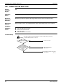
Accessories
Installation Manual
pc.
L Shape Reducer
pc.
18.9
2.5
1
For Main (Gas)
For Branch
1
Gas
3 (φ15.9 / φ12.7 / φ9.5)
Liquid
1 (φ9.5)
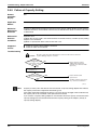
Note:
1. BP or Indoor Unit Max. Height - BP or Indoor Unit Min. Height → Max. 15m.
Set up BP and IU in 15m.
2. The piping connection must be cut so as to suit the piping sizes of the indoor unit which will be connected.
The same sizes should be used for the piping on the outdoor unit.
16
Conversion Formulae
kcal/h=kW×860
Btu/h=kW×3414
cfm=m³/min×35.3
Specifications
SiE18-201
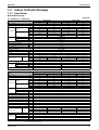
1.3
Specifications
Indoor Units (for Europe)
1.3.1 Heat Pump
Wall Mounted Type
2.5kW Class · 3.5kW Class
50Hz 230V
FTX25JAV1NB
Model
Rating Capacity
kW
FTX35JAV1NB
Cooling
Heating
Cooling
Heating
2.5
3.4
3.5
4.2
Front Panel Color
Almond White
m³/min
Air Flow Rates
cfm
H
7.1
8.4
7.4
8.4
M
5.9
7.0
6.0
7.1
L
4.6
5.7
4.7
5.9
H
251
297
261
297
M
208
247
212
251
L
162
201
166
208
Type
Fan
Cross Flow Fan
Motor Output
Speed
W
18
Steps
5 Steps and Auto
Air Filter
Removable / Washable / Mildew Proof
Running Current ★ (Rated)
A
Power Consumption ★ (Rated)
W
40
Power Factor ★
%
96.6
0.18
Temperature Control
Microcomputer Control
Dimensions (H×W×D)
mm
273×784×185
Package Dimensions (W×D×H)
mm
834×325×258
Weight
kg
7.5
Gross Weight
kg
Operation Sound
dBA
11
H
38
38
39
M
32
32
33
33
L
26
26
27
27
Heat Insulation
Piping
Connection
39
Both Liquid and Gas Pipes
Liquid
mm
Gas
mm
Drain
mm
φ 6.4
φ 9.5
φ12.7
φ18.0
Drawing No.
3D027497B
3D027498B
FTXD25KZV1B
FTXD35KZV1B
50Hz 230V
Model
Rating Capacity
kW
Cooling
Heating
Cooling
Heating
2.5
3.4
3.5
4.2
Front Panel Color
Almond White
m³/min
Air Flow Rates
cfm
H
7.5
8.0
7.9
8.0
M
5.8
6.4
6.1
6.5
L
4.0
4.8
4.3
5.0
H
265
282
279
282
M
203
226
215
229
L
141
169
152
177
Type
Fan
Cross Flow Fan
Motor Output
Speed
W
18
Steps
5 Steps and Auto
Air Filter
Removable / Washable / Mildew Proof
Running Current ★ (Rated)
A
Power Consumption ★ (Rated)
W
40
Power Factor ★
%
96.6
0.18
Temperature Control
Microcomputer Control
Dimensions (H×W×D)
mm
273×784×185
Package Dimensions (W×D×H)
mm
834×325×258
Weight
kg
8
Gross Weight
kg
11
Operation Sound
dBA
H
38
38
39
M
32
32
33
33
L
25
25
26
26
Heat Insulation
Piping
Connection
39
Both Liquid and Gas Pipes
Liquid
mm
Gas
mm
Drain
mm
Drawing No.
φ12.7
φ18.0
3D029436
★
Specifications
φ 6.4
φ 9.5
3D029437
Refer to Engineering Data Book.
17
Specifications
SiE18-201
5.0kW Class · 6.0kW Class
50Hz 230V
FTXD50JV1B
Model
Rating Capacity
kW
FTXD60JV1B
Cooling
Heating
Cooling
Heating
5.0
6.5
6.0
7.2
Front Panel Color
Almond White
m³/min
Air Flow
Rates
cfm
H
12.3
14.9
13.0
16.5
M
10.7
12.8
11.5
13.7
L
9.1
10.5
9.9
11.1
H
434
526
459
582
M
378
452
406
484
L
321
371
349
392
Type
Fan
Cross Flow Fan
Motor Output
Speed
W
54
Steps
5 Steps and Auto
Air Filter
Removable / Washable / Mildew Proof
Running Current ★ (Rated)
A
0.18
0.17
0.20
Power Consumption ★ (Rated)
W
40
38
45
45
Power Factor ★
%
96.6
97.2
97.8
97.8
44
Temperature Control
Microcomputer Control
Dimensions (H×W×D)
mm
298×1,050×190
Package Dimensions (W×D×H)
mm
1,183×367×289
Weight
kg
12
Gross Weight
kg
Operation Sound
dBA
16
H
44
42
45
M
40
37
41
39
L
35
32
37
34
Heat Insulation
Piping
Connection
0.20
Both Liquid and Gas Pipes
Liquid
mm
Gas
mm
Drain
mm
Drawing No.
φ 6.4
φ12.7
φ15.9
φ18.0
3D029183
3D029184
7.1kW Class
50Hz 230V
FTXD71JV1B
Model
Cooling
Rating Capacity
kW
Front Panel Color
8.5
Almond White
m³/min
Air Flow
Rates
cfm
H
13.7
M
11.8
14.1
L
9.9
11.1
17.3
611
H
484
M
417
498
L
349
392
Type
Fan
Heating
7.1
Cross Flow Fan
Motor Output
Speed
W
54
Steps
5 Steps and Auto
Air Filter
Removable / Washable / Mildew Proof
Running Current ★ (Rated)
A
0.22
Power Consumption ★ (Rated)
W
50
50
Power Factor ★
%
98.8
98.8
Temperature Control
0.22
Microcomputer Control
Dimensions (H×W×D)
mm
298×1,050×190
Package Dimensions (W×D×H)
mm
1,183×367×289
Weight
kg
12
Gross Weight
kg
Operation Sound
dBA
46
46
M
42
40
L
37
Heat Insulation
Piping
Connection
16
H
34
Both Liquid and Gas Pipes
Liquid
mm
φ 9.5
Gas
mm
φ15.9
Drain
mm
Drawing No.
φ18.0
3D029185
★
Refer to Engineering Data Book.
Conversion Formulae
kcal/h=kW×860
Btu/h=kW×3414
cfm=m³/min×35.3
18
Specifications
SiE18-201
Specifications
Duct Connected Type
2.5kW Class · 3.5kW Class
50Hz 230V
CDX25HAV1NB
Model
Rating Capacity
kW
CDX35HAV1NB
Cooling
Heating
Cooling
Heating
2.5
3.86
3.5
4.42
Front Panel Color
—
H
m³/min
Air Flow Rates
cfm
13.0
M
12.0
L
11.0
H
459
M
424
L
388
Type
Fan
Sirocco Fan
Motor Output
W
47
Steps
5 Steps and Auto
Running Current ★ (Rated)
A
0.40
Power Consumption ★ (Rated)
W
85
Power Factor ★
%
92.4
Speed
Air Filter
—
Temperature Control
Microcomputer Control
Dimensions (H×W×D)
mm
260×900×580
Package Dimensions (W×D×H)
mm
1,070×719×354
Weight
kg
23
Gross Weight
kg
Operation Sound
dBA
32
H
39
40
39
40
M
37
38
37
38
L
36
36
36
36
Heat Insulation
Piping
Connection
Both Liquid and Gas Pipes
Liquid
mm
φ 6.4
Gas
mm
φ 9.5
Drain
mm
φ 27.2(3/4B)
Drawing No.
3D024989
3D024990
CDX50HAV1NB
CDX60HAV1NB
5.0kW Class · 6.0kW Class
Model
Rating Capacity
kW
50Hz 230V
Cooling
Heating
Cooling
Heating
5.0
6.13
6.0
7.32
Front Panel Color
—
m³/min
Air Flow Rates
cfm
H
13.0
14.5
M
12.0
13.0
L
11.0
11.5
H
459
512
M
424
459
L
388
406
Type
Fan
Sirocco Fan
Motor Output
Speed
W
47
Steps
5 Steps and Auto
Air Filter
—
Running Current ★ (Rated)
A
0.40
Power Consumption ★ (Rated)
W
85
95
Power Factor ★
%
92.4
91.8
0.45
Temperature Control
Microcomputer Control
Dimensions (H×W×D)
mm
260×900×580
Package Dimensions (W×D×H)
mm
1,070×719×354
Weight
kg
24
Gross Weight
kg
Operation Sound
dBA
33
H
42
42
44
44
M
40
40
42
42
L
39
38
41
40
Heat Insulation
Piping
Connection
Both Liquid and Gas Pipes
Liquid
mm
Gas
mm
Drain
mm
Drawing No.
φ 6.4
φ12.7
3D024987
★
Refer to Engineering Data Book.
φ15.9
φ 27.2(3/4B)
3D024988
Conversion Formulae
kcal/h=kW×860
Btu/h=kW×3414
cfm=m³/min×35.3
Specifications
19
Specifications
SiE18-201
2.5kW Class · 3.5kW Class
50Hz 230V
CDX25JV1NB
Model
Rating Capacity
kW
CDX35JV1NB
Cooling
Heating
Cooling
Heating
2.5
3.86
3.5
4.42
Front Panel Color
—
H
m³/min
Air Flow Rates
cfm
13.0
M
12.0
L
11.0
H
459
M
424
L
388
Type
Fan
Sirocco Fan
Motor Output
Speed
W
47
Steps
5 Steps and Auto
Air Filter
Removable / Washable / Mildew Proof
Running Current ★ (Rated)
A
Power Consumption ★ (Rated)
W
85
Power Factor ★
%
92.4
0.40
Temperature Control
Microcomputer Control
Dimensions (H×W×D)
mm
260×900×580
Package Dimensions (W×D×H)
mm
1,070×719×354
Weight
kg
23
Gross Weight
kg
Operation Sound
dBA
32
H
39
40
39
40
M
37
38
37
38
L
36
36
36
36
Heat Insulation
Piping
Connection
Both Liquid and Gas Pipes
Liquid
mm
φ 6.4
Gas
mm
φ 9.5
Drain
mm
φ 27.2(3/4B)
Drawing No.
3D024989
3D024990
CDX50JV1NB
CDX60JV1NB
5.0kW Class · 6.0kW Class
Model
Rating Capacity
kW
50Hz 230V
Cooling
Heating
Cooling
Heating
5.0
6.13
6.0
7.32
Front Panel Color
—
m³/min
Air Flow Rates
cfm
H
13.0
14.5
M
12.0
13.0
L
11.0
11.5
H
459
512
M
424
459
L
388
406
Type
Fan
Sirocco Fan
Motor Output
Speed
W
47
Steps
5 Steps and Auto
Air Filter
Removable / Washable / Mildew Proof
Running Current ★ (Rated)
A
0.40
Power Consumption ★ (Rated)
W
85
95
Power Factor ★
%
92.4
91.8
0.45
Temperature Control
Microcomputer Control
Dimensions (H×W×D)
mm
260×900×580
Package Dimensions (W×D×H)
mm
1,070×719×354
Weight
kg
24
Gross Weight
kg
Operation Sound
dBA
33
H
42
42
44
44
M
40
40
42
42
L
39
38
41
40
Heat Insulation
Piping
Connection
Both Liquid and Gas Pipes
Liquid
mm
Gas
mm
Drain
mm
Drawing No.
φ 6.4
φ12.7
3D024987
★
Refer to Engineering Data Book.
φ15.9
φ 27.2(3/4B)
3D024988
Conversion Formulae
kcal/h=kW×860
Btu/h=kW×3414
cfm=m³/min×35.3
20
Specifications
SiE18-201
Specifications
Floor / Ceiling Suspended Dual Type
2.5kW Class · 3.5kW Class
50Hz 230V
FLX25HV1NB
Model
Rating Capacity
kW
FLX35HV1NB
Cooling
Heating
Cooling
Heating
2.5
3.86
3.5
4.42
Front Panel Color
Almond White
m³/min
Air Flow Rates
cfm
H
7.6
9.2
8.7
10.0
M
6.8
8.3
7.7
9.0
L
6.0
7.4
6.6
8.0
H
268
325
307
353
M
240
293
270
318
L
212
261
233
282
Type
Fan
Sirocco Fan
Motor Output
Speed
W
34
Steps
5 Steps and Auto
Air Filter
Removable / Washable / Mildew Proof
Running Current ★ (Rated)
A
0.32
0.34
Power Consumption ★ (Rated)
W
70
74
78
78
Power Factor ★
%
95.1
94.6
94.2
94.2
Temperature Control
0.36
Microcomputer Control
Dimensions (H×W×D)
mm
490×1,050×200
Package Dimensions (W×D×H)
mm
1,100×566×284
Weight
kg
16
Gross Weight
kg
Operation Sound
dBA
22
H
37
37
38
39
M
34
34
35
36
L
31
31
32
33
Heat Insulation
Piping
Connection
Both Liquid and Gas Pipes
Liquid
mm
φ 6.4
φ 6.4
Gas
mm
φ 9.5
φ12.7
Drain
mm
φ18.0
φ18.0
FLX50JV1B
FLX60JV1B
5.0kW Class · 6.0kW Class
Model
Rating Capacity
kW
50Hz 230V
Cooling
Heating
Cooling
Heating
5.0
6.1
5.7
6.7
Front Panel Color
Almond White
m³/min
Air Flow Rates
cfm
H
11.4
12.1
12.0
12.8
M
9.9
9.8
10.6
10.6
L
8.5
7.5
9.3
8.4
H
402
427
424
452
M
349
346
374
374
L
300
265
328
297
Type
Fan
Sirocco Fan
Motor Output
Speed
W
34
Steps
5 Steps and Auto
Air Filter
Removable / Washable / Mildew Proof
Running Current ★ (Rated)
A
0.43
0.42
0.45
Power Consumption ★ (Rated)
W
96
96
98
96
Power Factor ★
%
97.1
99.4
94.7
97.1
47
Temperature Control
Microcomputer Control
Dimensions (H×W×D)
mm
490×1,050×200
Package Dimensions (W×D×H)
mm
1,100×566×284
Weight
kg
17
Gross Weight
kg
Operation Sound
dBA
24
H
47
46
48
M
43
41
45
42
L
39
35
41
37
Heat Insulation
Piping
Connection
0.43
Both Liquid and Gas Pipes
Liquid
mm
φ 6.4
φ 6.4
Gas
mm
φ12.7
φ15.9
Drain
mm
Drawing No.
★
Refer to Engineering Data Book.
φ18.0
φ18.0
3D029186
3D029187
Conversion Formulae
kcal/h=kW×860
Btu/h=kW×3414
cfm=m³/min×35.3
Specifications
21
Specifications
SiE18-201
Floor Standing Type
2.5kW Class · 3.5kW Class
50Hz 230V
FVX25KZV1B
Model
Rating Capacity
kW
FVX35KZV1B
Cooling
Heating
Cooling
Heating
2.5
3.4
3.5
4.2
Front Panel Color
Almond White
m³/min
Air Flow Rates
cfm
H
8.1
9.2
8.3
9.2
M
6.2
7.0
6.3
7.1
L
4.3
4.8
4.3
5.0
H
286
325
293
325
M
219
247
222
251
L
152
169
152
177
Type
Fan
Cross Flow Fan
Motor Output
Speed
W
14
Steps
5 Steps and Auto
Air Filter
Removable / Washable / Mildew Proof
Running Current ★ (Rated)
A
0.14
Power Consumption ★ (Rated)
W
32
34
Power Factor ★
%
99.4
98.6
0.15
Temperature Control
Microcomputer Control
Dimensions (H×W×D)
mm
600×650×195
Package Dimensions (W×D×H)
mm
764×288×702
Weight
kg
13
Gross Weight
kg
Operation Sound
dBA
18
H
38
38
39
M
32
32
33
33
L
26
26
26
26
Heat Insulation
Piping
Connection
39
Both Liquid and Gas Pipes
Liquid
mm
Gas
mm
Drain
mm
Drawing No.
φ 6.4
φ 9.5
3D029440
★
Refer to Engineering Data Book.
φ12.7
φ 20.0
3D029441
Conversion Formulae
kcal/h=kW×860
Btu/h=kW×3414
cfm=m³/min×35.3
22
Specifications
SiE18-201
Part 3
Printed Circuit Board
Connector Wiring Diagram
and Name
1. Printed Circuit Board Connector Wiring Diagram and Name ................24
1.1
1.2
1.3
1.4
1.5
1.6
Branch Provider Unit BPMK928B42, B43 ............................................. 24
Outdoor Unit RMX140JVMB, RMX140JZVM ........................................ 25
FTX25 / 35J Series, FTXD25 / 35K Series, FVX25 / 35K Series .......... 28
FTXD50~71JV Series............................................................................ 30
CDX25~60HAV Series, CDX25~60JV Series ....................................... 32
FLX25~60HV Series, FLX50 / 60JV Series........................................... 34
Printed Circuit Board Connector Wiring Diagram and Name
23
Printed Circuit Board Connector Wiring Diagram and Name
SiE18-201
1. Printed Circuit Board Connector Wiring Diagram
and Name
1.1
Branch Provider Unit BPMK928B42, B43
Name of Connector
1) S1
2) S2 to S4
3) S5
Connector for Bypass Electronic Expansion Valve
Connector for Electronic Expansion Valve to Room A, B and C
Connector for Thermistors
1) FU1
2) FU2
3) FU3
4) FU4
5) LED-A
6) LED-B
7) LED 1 to 4
Fuse for Transformer
Fuse for Inter Connecting Wire to Room 1
Fuse for Inter Connecting Wire to Room 2
Fuse for Inter Connecting Wire to Room 3
LED for Service Monitor
LED for Service Monitor
LED for Fault Indication
Other Designations
Printed Circuit
Board
S5
S9
RED
LED B
S5
WHT
LED A
LED - A
LED - 1
LED - 2
LED - 3
LED - 4
X2M
1
S7
WHT
2
3
LED
1~4
THERMISTOR
S4
YLW
S4
S3
BLU
S3
S2
RED
S2
S1
WHT
S1
LED - B
X3M
1
2
3
X1M
X4M
3
1
FU3
FU2
2
2
FU1
3
FU3
24
1
FU4
FU4
FU2
FU1
Printed Circuit Board Connector Wiring Diagram and Name
SiE18-201
1.2
Printed Circuit Board Connector Wiring Diagram and Name
Outdoor Unit RMX140JVMB, RMX140JZVM
Heat Pump
RMX140JVMB, RMX140JZVMB
Printed Circuit
Board
Printed Circuit Board (1) (Control PCB)
Printed Circuit Board (2) (Filter PCB)
Printed Circuit Board (3) (Fan Control PCB)
Printed Circuit Board (4) (Indicator PCB)
Name of Connector
PCB 1
1) S101
2) S102
3) S103
4) S104
5) S105
6) S107
7) S108
8) S109
9) S110
10) S111
11) S114
12) S131
13) S132
14) S140
15) S151
Connector to PCB 3 (to S501)
Connector to PCB 3 (to S502)
Connector to PCB 2 (to S903)
Connector to PCB 2 (to S904)
Connector to SP (Low Pressure Sensor)
Connector to PCB 2 (to S907)
Connector to Y1E EVG (Electronic Expansion Valve)
Connector to Y2E EVL (Electronic Expansion Valve)
Connector to Y3E EVP (Electronic Expansion Valve)
Connector to Y1R (4 Way Valve)
Connector to Thermistors
Connector to HPS (High Pressure Switch)
Connector to PCB 2 (to S908)
Connector to Active Module
Connector to PCB 2 (to S951)
PCB 2
1) S903
2) S904
3) S906
4) S907
5) S908
6) S951
7) S952
Connector to PCB 1 (to S103)
Connector to PCB 1 (to S104)
Connector of Communication Wire to Each Indoor Units
Connector to PCB 1 (to S107)
Connector to PCB 1 (to S132)
Connector to PCB 1 (to S151)
Connector to Power Supply (N, L)
PCB 3
1) S501
2) S502
3) S504
4) S506
5) S514
6) S516
7) S517
Connector to PCB 1 (to S101)
Connector to PCB 1 (to S102)
Connector to FAN M1F
Connector to FAN M2F
Connector to FAN M1F
Connector to FAN M2F
Connector to C1R (Capacitor)
Printed Circuit Board Connector Wiring Diagram and Name
25
Printed Circuit Board Connector Wiring Diagram and Name
SiE18-201
Other Designations
1) H1P (LED A on PCB 4)
2) H2P (PCB 1)
3) H3P (PCB 3)
4) H4P (PCB 3)
5) LED 2~4 (PCB 4)
6) SW1, SW2 (PCB 4)
7) SW3 (PCB 4)
8) SW4 (PCB 4)
9) SW5 (PCB 4)
10) SW6 (PCB 4)
11) SW7 (PCB 4)
12) FU1 (PCB 1)
13) JP
LED for Outdoor Unit Status-normal
LED for Outdoor Unit Status-normal
LED for Outdoor Unit Fan Status-normal
LED for Outdoor Unit Fan Status-normal
Digital Service Monitor
Address Selection Switches
Forced Operation Mode Selection Switch (Cool↔Heat)
Pump Down Switch (Service Mode No. Down Switch)
Pump Down Switch (Service Mode No. Up Switch)
Initialize Switch
Test Operation Switch
Fuse 3.15Amps
Silent Select Switch
Printed Circuit
Board (1)
(Control PCB)
S102
H2P
S132
S103
S101
S108
S109
S110
S104
S114
S107
S105
S151
S140
FU1
S111
S131
26
Printed Circuit Board Connector Wiring Diagram and Name
SiE18-201
Printed Circuit Board Connector Wiring Diagram and Name
Printed Circuit
Board (2)
(Filter PCB)
S907
S906
S908
S952
S904
S903
S951
Printed Circuit
Board (3)
(Fan Control)
S502 S517
S516
Printed Circuit
Board (4)
(Indicator PCB)
S506 H4P S501
(LED501)
LED 2-4
H3P(LED500)
S504
SW6
S514
SW5
SW4
JP
H1P(LED A)
SW1 SW2
Printed Circuit Board Connector Wiring Diagram and Name
SW3
SW7
27
Printed Circuit Board Connector Wiring Diagram and Name
1.3
SiE18-201
FTX25 / 35J Series, FTXD25 / 35K Series,
FVX25 / 35K Series
Heat Pump
FTX25 / 35JAV1NB, FTXD25 / 35KZV1B, FVX25 / 35KZV1B
Printed Circuit
Board
Printed Circuit Board (1) (Control PCB)
Printed Circuit Board (2) (Signal Receiver PCB)
Printed Circuit Board (3) (Intelligent Eye Sensor PCB)
Name of Connector
1)
2)
3)
4)
5)
6)
7)
8)
Note:
28
S1
S6
S7
S21
S27, S36
S26
S32
S35
Connector for Fan Motor
Connector for Swing Motor (Horizontal Flap)
Connector for Fan Motor
Connector for Centralized Control to 5 Rooms
Connector for Control PCB
Connector for Signal Receiver PCB
Connector for Room Temp/Heat Exchanger Thermistor
Connector for Intelligent Eye Sensor PCB
Other designations
1) V1
Varistor
2) JA
Address Setting Jumper
JB
Fan Speed Setting when Compressor is OFF on Thermostat.
JC
Power Failure Recovery Function.
3) SW7
Operation Switch
4) LED1 (GRN) LED for Operation
5) LED2 (YLW) LED for Timer
6) LED3 (GRN) LED for Intelligent Eye
Printed Circuit Board Connector Wiring Diagram and Name
SiE18-201
Printed Circuit Board Connector Wiring Diagram and Name
Printed Circuit Board (1)~(3)
S1
Control P C B (1)
Signal receiver PCB(2)
S27
GRN
YLW GRN
LED1
LED2 LED3
SW7
12V check
Jumper
S7
ground
Intelligent eye
sensor P C B (3)
JA
JB
JC
S6
5V check
Jumper
S36
S21
S32
S26
S35
(RL001)
Printed Circuit Board (1)~(3) Detail
SW7
PCB1
S1
PCB2
V1
S27
12 V Check
GND
S7
JA
S6
S36
JB
JC
5V Check
S35
PCB3
S21
Printed Circuit Board Connector Wiring Diagram and Name
S32
S26
(RE001)
29
Printed Circuit Board Connector Wiring Diagram and Name
1.4
SiE18-201
FTXD50~71JV Series
Heat Pump
FTXD50 / 60 / 71JV1B
Printed Circuit
Board
Printed Circuit Board (1) (Control PCB)
Printed Circuit Board (2) (Power Supply PCB)
Printed Circuit Board (3) (Display PCB)
Printed Circuit Board (4) (Signal Receiver PCB)
Name of Connector
1) S1
2) S6
3) S8
4) S21
5) S24
6) S25, S27, S36
7) S26
8) S31, S32
9) S37
Connector for Fan Motor
Connector for Swing Motor (Horizontal Flap)
Connector for Swing Motor (Vertical Flap)
Connector for Centralized Control to 5 Rooms
Connector for Display PCB
Connector for Control PCB
Connector for Signal Receiver PCB
Connector for Room Temp/Heat Exchanger Thermistor
Connector for Power Supply PCB
1) V1
2) SW7 (S1W)
3) SW2 (S2W)
4) SW8 (S8W)
5) LED3 (GRN)
6) LED4 (YLW)
7) LED5 (RED)
8) LED A, LED B
Varistor
Operation Switch
Address Switch
Cleaning Indicator Reset Switch
LED for Operation
LED for Timer
LED for Cleaning
LED for Service Monitor
Other Designations
Printed Circuit
Board (1)
(Control PCB)
SW2
S21
S32
S8
S6
S26
SW8
S37
S24
30
LEDB
LEDA
JB, JC Jumper
(ML008)
Printed Circuit Board Connector Wiring Diagram and Name
SiE18-201
Printed Circuit Board Connector Wiring Diagram and Name
Printed Circuit
Board (2)
(Power Supply
PCB)
S1
S36
WIRE
(WHITE)
V1
H2
FU1
(3,15A)
WIRE(WHITE)
H3
WIRE(BLACK)
WIRE
(GREEN/YELLOW)
H1
WIRE(RED)
FERRITE CORE
(ML009)
Printed Circuit
Board (3)
(Display PCB)
LED3(H1P)
(Green)
Printed Circuit
Board (4)
(Signal Receiver
PCB)
LED4(H2P)
(Yellow)
LED5(H3P)
(Red)
S25
(ML010)
S31
S27
SW7(S1W)
Signal receiver
(ML011)
Printed Circuit Board Connector Wiring Diagram and Name
31
Printed Circuit Board Connector Wiring Diagram and Name
1.5
SiE18-201
CDX25~60HAV Series, CDX25~60JV Series
Heat Pump
CDX25 / 35 / 50 / 60HAV1NB,
CDX25 / 35 / 50 / 60JV1NB
Printed Circuit
Board
Printed Circuit Board (1) (Control PCB)
Printed Circuit Board (3) (Intelligent Eye Sensor PCB)
Name of Connector
1)
2)
3)
4)
5)
6)
7)
Note:
32
S1
S6
S7
S21
S36
S26
S35
Connector for Fan Motor
Connector for Swing Motor (Horizontal Flap)
Connector for Fan Motor
Connector for Centralized Control to 5 Rooms
Connector for Control PCB
Connector for Signal Receiver PCB
Connector for Intelligent Eye Sensor PCB
Other designations
1) V1
Varistor
2) JA
Address Setting Jumper
JB
Fan Speed Setting when Compressor is OFF on Thermostat.
JC
Power Failure Recovery Function.
3) LED1 (GRN) LED for Operation
4) LED2 (YLW) LED for Timer
5) LED3 (GRN) LED for Intelligent Eye
Printed Circuit Board Connector Wiring Diagram and Name
SiE18-201
Printed Circuit Board Connector Wiring Diagram and Name
Printed Circuit Board (1)~(3)
S1
Control P C B (1)
12V check
Jumper
S7
ground
sensor PCB(3)
JA
JB
JC
S6
5V check
Jumper
S36
S21
S26
S35
(RL001)
Printed Circuit Board (1)~(3) Detail
SW7
PCB1
S1
PCB2
V1
S27
12 V Check
GND
S7
JA
S6
S36
JB
JC
5V Check
S35
PCB3
S21
Printed Circuit Board Connector Wiring Diagram and Name
S32
S26
(RE001)
33
Printed Circuit Board Connector Wiring Diagram and Name
1.6
SiE18-201
FLX25~60HV Series, FLX50 / 60JV Series
Heat Pump
FLX25 / 35HV1NB, FLX50 / 60JV1B
Printed Circuit
Board
Printed Circuit Board(1) (Control PCB)
Printed Circuit Board(2) (Power Supply PCB)
Printed Circuit Board(3) (Display PCB)
Printed Circuit Board(4) (Signal Receiver PCB)
Name of Connector
1) S1
2) S6
3) S7
4) S21
5) S24
6) S25
7) S26
8) S27
9) S31
10) S32
11) S36
12) S37
Connector for Fan Motor (Power Supply)
Connector for Swing Motor
Connector for Fan Motor
Connector for Centralized Control
Connector for PCB3 (to S25)
Connector for PCB1 (to S24)
Connector for PCB4 (to S27)
Connector for PCB1 (to S26)
Connector for Thermistor (R1T)
Connector for Thermistor (R2T,R3T)
Connector for PCB1 (to S37)
Connector for PCB2 (to S36)
1) FU
2) S2W
3) S7W
4) S8W
5) H1P
6) H2P
7) H3P
8) LED A,B
9) JB
Fuse 3.15A
Address Switch
Operation Switch
Cleaning Indicator Reset Switch
LED for Filter Sign
LED for Timer
LED for Operation
LED for Service Monitor
Control Function Change Jumper (When cut → Setting of Fan RPM “0”
during Thermostat Off)
Control Function Change Over (When cut → No Auto Restart Function)
Other Designation
10) JC
34
Printed Circuit Board Connector Wiring Diagram and Name
SiE18-201
Printed Circuit Board Connector Wiring Diagram and Name
Printed Circuit
Board (1)
(Control PCB)
S21
S2W
JC
JB
S7
S32
S6
S8W
S24
LED A,B
for Sevice Monitor
S37
S11
S15
S26
Printed Circuit
Board (2)
(Power Supply
PCB)
Printed Circuit Board Connector Wiring Diagram and Name
35
Printed Circuit Board Connector Wiring Diagram and Name
SiE18-201
Printed Circuit
Board (3)
(Display PCB)
Printed Circuit
Board (4)
(Signal Receiver
PCB)
36
Printed Circuit Board Connector Wiring Diagram and Name
SiE18-201
Part 4
Main Functions
Indoor Unit
1. Main Functions......................................................................................38
1.1 Main Functions in Split Type ................................................................. 38
1.2 SkyAir .................................................................................................... 51
1.3 Cautions when SkyAir [Auto] [FAN] are used........................................ 53
Main Functions
37
Main Functions
SiE18-201
1. Main Functions
1.1
Main Functions in Split Type
1.1.1 Wide Angle Flaps, Louvers and Auto-Swing
For FTX25/35J
Series Only
Outline of the
Action
It can be commanded for J type by means of a user setting to select either any one desired
position among the five-step directions of air flow adjusted on a remote controller, or Autoswing.
5
4
3
2
1
(RL006)
Initial
Although the liquid crystal display of the five-step directions of the air flow is common for the
modes of Cooling·Dry/Heating as illustrated above, in fact the range of the swing angle is
slightly different in every operation mode.
The position a user sets will be selected among the five positions calculated preliminarily and
evenly divided into four partitions which were taken from the upper and lower flap angle’s range
limits of each mode.
When Auto-swing is chosen, the flap swings in the swing range which meets the operation
mode selected.
Heating mode
0 degree based on
the horizontal line.
Cooling /Dry mode
Fan mode
0 degree based on
the horizontal line.
0 degree based on
the horizontal line.
0˚
10˚
20˚
25˚
45˚
45˚
(RL007)
(RL008)
(RL009)
∗ Fan mode is available for the models of cooling-only.
Others
38
The vertical louver can be adjusted manually. The movable range is 60 degrees for left or
right, and total 120 degrees.
A diffuser is not available for J type.
Main Functions
SiE18-201
Main Functions
1.1.2 Fan Speed Control for Indoor Units
For FTX25/35J
Series
Control Mode
The airflow rate can be automatically controlled depending on the difference between the set
temperature and the room temperature. This is done through phase control and Hall IC control.
For more information about Hall IC, refer to ‘Hall IC check (A6)’ on page 258.
Phase Steps
Phase control and fan speed control contains 8 steps: LLL, LL, L, ML, M, HM, H and HH.
Step
LLL (Heating thermostat
OFF)
LL (Cooling thermostat
OFF)
L
ML
M
MH
H
HH (Powerful)
Cooling
Heating
Dry mode
H type : 500 - 860 rpm
(During powerful operation :
850 - 910 rpm)
J type : 800 - 980 rpm
(During powerful operation :
1050 rpm)
(RL010)
(RL010)
= Within this range the airflow rate is automatically controlled when the AIRFLOW
ADJUSTING button is set to AUTOMATIC
Note:
Automatic Air
Flow Control for
Heating
1. During powerful operation, fan operate H tap + 50 - 70 rpm.
2. Fan stops during defrost operation.
The following drawing explains the principle for fan speed control for heating:
Thermostat
setting
temperature
Phase control
-0.5˚C
-0.5
L
-1.5˚C
-1.5
ML
M
fan speed
Note:
Automatic Air
Flow Control for
Cooling
-1
-1˚C
Temperature difference between
-2
-2˚C ambient and set temperature
(RL012)
When there is no operation and the night set mode turns on, the step is low. Refer to “Night set
mode” on page 42.
The following drawing explains the principle of fan speed control for cooling:
fan speed
M
+2˚C Temperature difference between
+2
ML
ambient and set temperature
+1
+1˚C
L
+1.5˚C
+1.5
+0.5˚C
+0.5
Thermostat
setting
temperature
Phase control
(RL013)
1.1.3 Signal Receiving Sign
When the indoor unit receives a signal from the remote controller, the unit emits a signal
receiving sound.
1.1.4 Air Purifying Filter
For FTX25/35 J
Series
Main Functions
The air purifying filter (electrostatic filter) catches pollen or smoke of cigarette as small as 0.01
micron through electro static charging. An activated carbon deodorizing filter in a net shape is
also mounted to absorb and minimize fine odor particles.
39
Main Functions
SiE18-201
1.1.5 Washable Grille
Washable grille is for FTK(X)25/35 J
Note:
Refer to P97 in Si12-001 for FTK25/35 J Series “Cleaning the air filters.”
1.1.6 Mold Proof Air Filter
For FTK(X)25/35 J
Series
The filter net is treated with mold resisting agent TBZ (harmless, colorless, and odorless). Due
to this treatment, the amount of mold growth is much smaller than that of normal filters.
1.1.7 Pre-Heat Operation (Heat Pump Only)
1. When the equipment has been stopped, the compressor is warmed up by passing a small
single-phasing current through the compressor motor so that the start up is speeded up.
2. The power consumption during warming up is about 15 to 35W.
3. This function operates only when the outside temperature is low (less than about 10ºC) so
that power saving is achieved.
Outside temperature
For FTK(X)25/35 J
Series
12°C
10°C
OFF
ON
OFF
(ML045)
1.1.8 Hot Start Function (Heat Pump Only)
In order to prevent the cold air blast that normally comes when heating is started, the
temperature of the heat exchanger of the indoor unit is detected, and either the air flow is
stopped or is made very weak thereby carrying out comfortable heating of the room.
*The cold air blast is also prevented using a similar control when the defrosting operation is
started or when the thermostat gets turned ON.
During defrosting or when the thermostat is on in heating mode, the indoor heat exchanger
temperature
≥ 29˚C to fan starts to avoid cold draft.
1.1.9 Program Dry Function
Program dry function removes humidity while preventing the room temperature from lowering.
Since the microcomputer controls both the temperature and air flow volume, the temperature
adjustment and fan adjustment buttons are inoperable in this mode.
In the Case of
Inverter Units
The microcomputer automatically sets the temperature and fan settings. The difference
between the room temperature at startup and the temperature set by the microcomputer is
divided into two zones. Then, the unit operates in the dry mode with an appropriate capacity for
each zone to maintain the temperature and humidity at a comfortable level.
Room temperature at
startup
Temperature (ON point) Frequency switching
at which operation starts point
temperature at
24ºC Room
startup
18ºC
17ºC
40
Temperature difference
for operation stop
1.5ºC
0.5ºC
18ºC
1.0ºC
—
Main Functions
SiE18-201
Main Functions
ON point
Frequency switching
point
0.5 C
OFF point
5 min
Compressor
control
Stop
LHz
*55Hz
Indoor unit fan
Extra-low air flow
Stop
5 min
Stop
LHz
Extra-low air flow
*55Hz
LHz
Stop
Stop
Stop
Low air flow
Low air flow
LHz indicates low frequency. Item marked with varies depending on models.
(ML047)
1.1.10 Automatic Operation (Heat Pump Only)
Automatic Cooling/Heating Function
When the AUTO mode is selected with the remote controller, the microcomputer automatically
determines the operation mode from cooling and heating according to the room temperature
and setting temperature at the time of the operation startup, and automatically operates in that
mode.
The unit automatically switches the operation mode to cooling or heating to maintain the room
temperature at the main unit setting temperature.
Detailed
explanation of the
function
1. Remote controller setting temperature is set as automatic cooling / heating setting
temperature (18 to 30˚C).
2. Main unit setting temperature equals remote controller setting temperature plus correction
value (correction value / cooling: 0 deg, heating: 2 deg.).
3. Operation ON / OFF point and mode switching point are as follows.
Heating → Cooling switching point: Room temperature ≥ Main unit setting temperature
+2.5 deg.
Cooling → Heating switching point: Room temperature < Main unit setting temperature –
2.5 deg.
Thermostat ON / OFF point is the same as the ON / OFF point of cooling or heating
operation.
4. During initial operation
Room temperature ≥ Remote controller setting temperature: Cooling operation
Room temperature < Remote controller setting temperature: Heating operation
Heating /
cooling switching point
(Heating thermostat
OFF point)
Main unit setting
temperature
(Cooling thermostat
OFF point)
Cooling /
heating switching point
2.5 deg.
or higher
(1.5 deg.)
or higher
Cooling
operation
Heating
operation
Cooling
operation
Less than
(1.5 deg.)
2.5 deg.
or higher
With compressor capacity supplied
With no compressor capacity supplied
(RL022)
However, in the automatic Powerful cooling/heating mode, the guard timer is set as follows to
prevent hunting in cooling / heating mode.
Main Functions
41
Main Functions
SiE18-201
1.1.11 Night Set Mode
When the OFF Timer is set, the New Night Set Circuit automatically activates.
The Night Set Circuit automatically switches the fan speed to a low setting to minimize operating
noise. On the other hand, the New Night Set Circuit maintains the airflow setting made by users.
(Some models are equipped with an Night Set Circuit ON switch.)
The Night Set
Circuit
The Night Set Circuit continues heating or cooling the room at the set temperature for the first
one hour, then automatically lowers the temperature setting slightly in the case of cooling, or
raises it slightly in the case of heating, for economical operations. This prevents excessive
heating in winter and excessive cooling in summer to ensure comfortable sleeping conditions,
and also conserves electricity.
Cooling
Operation
A
0.5°C
1 hour
Timer operation
Night Set Circuit ON
A :
B :
30 minutes
+0.5°C
temperature shift
Temperature
setting +1°C
Temperature
setting +0.5°C
B
Temperature
setting
Operation stops
at the set hours
0.5°C
A +0.5°C temperature shift
B Temperature setting remains the same
When outside temperature is normal and
room temperature is at set temperature.
• When outside temperature is high (27°C or higher).
•
(ML048)
Heating
Operation
2°C
Thermostat
setting
Timer operation
Night Set Circuit ON
1 hour later
(ML049)
1.1.12 Self-Diagnosis Digital Display
The microcomputer continuously monitors main operating conditions of the indoor unit, outdoor
unit and the entire system. Should an abnormality occur, the LCD remote controller displays
information and the indicators on the indoor and outdoor units light. These indications allow
prompt maintenance operations.
1.1.13 Self-Diagnosis LED Display
The lighting patterns of the indoor unit LEDs (Operation, Timer and Dry/Hot Start indicators) and
the LEDs on the outdoor unit’s printed circuit board allow diagnosis of problem areas and faulty
conditions of the interconnecting wire.
Note:
Self-Diagnosis LED display is not equipped for FTX25/35 J series.
1.1.14 Auto-Restart Function
Even if a power failure (including one for just a moment) occurs during the operation, the
operation restarts in the condition before power failure automatically when power is restored.
(Note) It takes 3 minutes to restart the operation because the 3-minute standby function is
activated.
42
Main Functions
SiE18-201
Main Functions
1.1.15 Intelligent Eye
For FTX25/35 J
Series Only
Outline
The function that detects existence of humans in the air-conditioned room and reduces the
capacity when no humans are available in the room in order to save electricity by means of a
human motion sensor.
Processing
1. Detection method by human motion sensor
sampling (20msec)
Sensor output
1sec
If the sensor detects the outputs 10 times/sec.
or more, it judges humans are available.
High
Low
(Human motion)
Human detection ON
signal
OFF
(RL019)
This sensor detects human motion by receiving infrared rays and displays the pulse wave
output.
A micro computer in an indoor unit carries out a sampling every 20 msec. and if it detects 10
cycles of the wave in one second in total (corresponding to 20msec.° 10 = 100msec.), it
judges human is in the room as the motion signal is ON.
2. The motions (for example: in cooling)
within 20
minutes.
20 min.
20 min.
40 min.
Human detection ON
signal
OFF
RESET.
C/O Set temp. + 2˚C
H/P Set temp. - 2˚C
Set temp.
Frequency at set temp. + 2˚C
MaxHz
Compressor Mi nHz
speed
0Hz
Human motion
detection LED
Remote controller
human motion
detection signal
sensor button
Operation
The lower limit by detecting
human.
(Prohibition of thermostat-off)
ON
OFF
in case of
thermostat-off
ON
OFF
ON
OFF
Fan speed (1)
Set speed
Set speed
Set speed - 50 rpm
OFF
(RL020)
When a micro computer doesn’t have a signal from the sensor in 20 minutes, it judges that
no body is in the room and turns off the human detection LED, operating the unit in
temperature sifted 2˚C from the set temperature. (Cooling : 2˚C higher, Dry: 1˚C higher and
Auto : according to the operation mode at that time.)
★1 In case of Fan mode, the fan speed reduces by 50 rpm.
Main Functions
43
Main Functions
SiE18-201
Since the set temperature is shifted by 2˚C higher for 40 minutes, compressor speed
becomes low and can realize energy saving operation. But as thermostat is prone to be off
by the fact that the set temperature has been shifted, the thermostat-off action is prohibited
in 40 minutes so as to prevent this phenomena.
After this 40 minutes, the prohibition of the thermostat-off is cancelled and it can realize the
conditions to conduct thermostat-off depending on the room temperature. In or after this forty
minutes, if the sensor detects human motion detection signal, it turns on “Human detection
LED” and let the set temperature and the fan speed return to the original set point, keeping a
normal operation.
The dry operation can’t command the setting temperature with a remote controller, but
internally the set temperature is shifted by 1˚C.
Others
1.1.16 Good Sleep Cooling Control
For FTX25/35 J
Series Only
Outline
The function to create deep sleeping and to offer good sleep by altering the set temperatures in
certain intervals to give temperature variation to a living space based on “1/f temperature
fluctuation” principle, in case of going to bed while air conditioner keeps operating in cooling
mode.
Processing
[Unit: min]
one cycle
20
Set temp.+1˚C
the set temperature
before the good sleep
cooling
60
Entering the good
sleep control (ON)
Notes:
44
17
21
63
63
repeating
41
22
63
63
27
20
20
60
(RL021)
1. Each timer’s counting/stop is not related to a thermostat ON/OFF.
2. When the sleeping control works by the OFF timer, the shift from the set temperature should
be just 1˚C with this control function.
(The temperature shift of the normal OFF-timer will not be carried out. However, the passed
time should be remembered since the OFF-timer was set.)
3. While operation with the good sleep cooling control and off-timer setting, if the signal of the
good sleep cooling OFF signal comes, the level of the set temperature shift should be set
corresponding to the same with an existing value in accordance with the passed time since
the OFF-timer was set.
4. When the good sleep cooling control is on while a normal operation with a OFF-timer is
going on, once returning to the original criterion which doesn’t shift the timer’s set
temperature, and the shift alteration at every sequence by 1˚C is carried out in accordance
with the value above mentioned.
5. Fan speed will change by the alteration of the set temperature by 1˚C at the automatic fan
speed operation mode, and it causes an alteration of fan noise. So, the fan tap should be
fixed at L tap position during the good sleep cooling even at the auto fan speed operation.
6. The function of the good sleep cooling is cancelled, when the good sleep cooling operation
is off or operation OFF command is received or also the operation mode changes to the
mode except cooling.
7. The priority order for each function is ; ‘Powerful’, ‘Intelligent eye’, ‘Good sleep’, and ‘Night
set mode’.
Main Functions
SiE18-201
Main Functions
1.1.17 Program Dry Operation
By the function of the microcomputer, program dry operation reduces the humidity keeping the
temperature in a minimum drop. Room temperature and air volume can not be controlled by
room temperature adjusting button and air volume adjusting button because they are controlled
automatically. When the program dry function starts, dry operation is provided, and then it
repeats 5 minute suspension and 4-minute dry operation alternately. When the room
temperature rises, it repeats the above process from the beginning.
Room temperature at starting of
program dry operation
Above 24˚C
18˚C~24˚C
Below 18˚C
Program dry activating
temperature ★1
Room temperature at starting of
program dry operation
Room temperature at starting of
program dry operation
18˚C
Differential ★2
1.5 deg
1.0 deg
1.0 deg
★1 Dry operation activating (compressor on) temperature
★2 Room temperature difference between activation and suspension of dry operation
Activating temp.
Differential
Suspention temp.
4 minutes
5 minutes
(RL001)
Note:
1. The program dry function is not operated when the room temperature is at 18˚C or less.
2. In monitoring operation, fan rotates 5 seconds after the compressor starts its operation.
Compressor
Suspension
Operation
5 seconds
Indoor fan
Suspension
L tap
(RL002)
Main Functions
45
Main Functions
SiE18-201
1.1.18 Cooling Monitoring Function
Monitoring function is activated while cooling and program dry operation are suspended.
Compressor ON
Compressor OFF
e
<B>
c
Differential
d
<A>
TOF
a
b
TM1 TM2
TM1 or less
TM1
TOF or more
TM2 or less
(RL003)
TOF: Compressor recycling guard timer (3-minute timer)
TM1: 5-minute timer
TM2: 4-minute timer
<A> At cooling: Temperature set by wireless remote controller
At program dry operation: Temperature at suspension
<B> Temperature set by wireless remote controller + 1 deg. (Cooling operation)
Temperature set (Program dry operation)
Even if the suction temperature remains in the differential range, a compressor is cycled ON
and OFF.
DETAIL: When the suction temperature rises again to <A> (point b) after the suction
temperature is dropped to <A> and the compressor turns OFF (point a) the 5-minute timer
starts.
After that, when the suction temperature is within the differential range, even after a lapse of 5
minutes, the compressor is forced to turn ON (point c).
When the suction temperature is still in the differential range, after another 4 minutes of
compressor ON, the compressor is forced to turn OFF (point d).
The 5 and 4-minute timers are effective only within the differential temperature range, and when
the air suction temperature is reached to <B> or <A> while the timers are counting, timers are
reset and the compressor is turned ON or OFF.
(Note, however, that function of placing the compressor in a 3-minute compressor recycling
guard timer is provided at point e.)
While the compressor is OFF, the indoor fan operation is controlled by tap A during cooling
mode.
In the program dry mode, the indoor fan starts operating five seconds after the compression
starts, and it stops operating when the compressor shuts down.
FLE18HV1LS, FL35/50HV1
46
A
Remote controller setting
Main Functions
SiE18-201
Main Functions
1.1.19 Freeze Protection Function
When the indoor heat exchanger temperature falls below “A”˚C in cooling or program dry
operation,
the compressor and the outdoor fan are forced to turn OFF, and
the indoor fan rotates at the L tap (in cooling operation) or W2 tap (in program dry operation).
Note that this function is not activated for 6 minutes after compressor turns ON.
When the indoor heat exchanger reaches “B”˚C, the compressor and the outdoor fan restart the
operations. However, because the compressor recycling guard timer (3-minute timer) takes
priority, the compressor and the outdoor fan don’t restart the operation during this timer is ON.
A
3
FLE18HV1LS, FL35/50HV1
B
13
W2
LL
Indoor heat exchanger temperature(˚C)
B
A
6 minutes
ON
Compressor and outdoor fan
OFF
(RG001)
1.1.20 Auto-Restart Function
Even if a power failure (including one for just a moment) occurs during the operation, the
operation restarts in the condition before power failure automatically when power is restored.
(Note) It takes 3 minutes to restart the operation because the 3-minute standby function is
activated.
1.1.21 3-Minutes Standby Function
When the compressor turns OFF, it doesn’t turn ON for 3 minutes
1.1.22 Auto-Swing of Flap(s)
Auto-swing angles are about “A” degrees when the fan is ON, and about “B” degrees when the
cooling or program dry operation is ON. The up-and-down swing of the flaps widens the
direction of wind.
When [SWING] is selected, the flap swinging range depends
on the operation mode. (See the figure.)
DRY
COOL
FAN
Note:
Main Functions
Notes on flap angles
47
Main Functions
SiE18-201
1.1.23 Air Flow Automatic (Auto Fan Speed)
In cooling operation, if automatic airflow has been selected, the wind flow is determined
according to the room temperature and the temperature setting.
BLADE ANGLE
UP/DOWN : (AUTOMATIC)
RIGHT/LEFT : (MANUAL)
COOLING
DRY
FLAP
20˚
40˚
20˚
40˚
45
˚
45
˚
(RL005)
1.1.24 Night Set Mode Function
This mode automatically keeps temperature slightly higher than the temperature setting. In this
way, there is no need to worry about overcooling while sleeping, and it also saves on electricity.
Set the OFF timer.
The unit will cool the room at the set temperature for 1 hour from when the timer
starts counting.
After that, the unit will raise temperature 0.5˚C higher than the set temperature and
cool for 30 minutes.
After that, the unit will raise temperature another 0.5˚C and continue cooling at that
temperature.
Setting the OFF timer forcibly changes the airflow adjustment to the tap-L setting.
It is possible to change the airflow setting while the OFF timer is in operation.
However, changing the airflow setting cancels the shift-up of the set temperature.
Timer start
0.5˚C
0.5˚C
30-minutes
Set temp.
60-minutes
(M1101)
Note:
48
No higher temperature setting on program Dry or Auto operation.
Main Functions
SiE18-201
Main Functions
1.1.25 Emergency Operation Function (ON/OFF Switch)
The unit can be turned ON only by pressing ON/OFF operation switch. This is convenient when
the remote controller cannot be found or if the batteries are dead.
The operation condition is as follows:
Operation mode
Fan speed
Set temperature
Cool
Auto
22˚C
Pressing the switch again will turn the unit OFF.
ON/OFF button
Operation lamp
Timer lamp
Cleaning lamp
(Green)
(Yellow)
(Red)
Receiver
ON/OFF button
(M1102)
1.1.26 Powerful Operation
During cool and program dry operation, when the POWERFUL button on the remote controller
is pressed, the thermistor setting is changed to the lowest setting of the remote controller and
the fan runs at the maximum rpm (Note). During fan operation, air is blown at the maximum fan
rpm.
Note:
Max. fan rpm = H tap set by remote controller + 50 rpm
Notes on POWERFUL Operation
In COOL mode
To maximize the cooling effect, the temperature setting is fixed to 18˚C and the air flow rate
is fixed to the maximum setting. (H tap + 50 r.p.m)
The temperature and air flow settings are not variable.
In DRY mode
The temperature setting is lowered by 3˚C and the air flow rate is slightly increased. You can
repeat POWERFUL operation if you need even more dehumidification.
Main Functions
49
Main Functions
SiE18-201
1.1.27 Filter Check Indicator
The filter check indicator located at the center of the unit will indicate the time for
cleaning the air filters.
The indicator will indicate an appropriate cleaning time depending on the environment (dusty
place or not). This will prevent you from forgetting filter cleaning and also prevent performance
drop that might be caused by using clogged filters and wasteful use of electricity by
approximately 8%.
<Contents of indication>
Sensed by the operation hours and the fan motor voltage
1. Filter clogging (★)
0
168 hours
336 hours
Definite
(M1103)
2. Accumulated operation hours
0
336 hours
(M1104)
Indicates the earlier one of the above 1 or 2.
★ This indicator utilizes the characteristic that the fan motor voltage drops as the crossflow fan
gets clogged; it does not detects the amount of filter clogging.
Note:
When the power supply is reset, the accumulated operation hour is not reset.
After cleaning and mounting the filters, press the reset button located inside the panel of the
unit.
Control panel
CLEANING LAMP
RESET button
• Push this button to turn the
CLEANING lamp off.
(M1105)
50
Main Functions
SiE18-201
SkyAir
Existing cooling/heating preset temperature range has been changed.
17
18
19
20
21
22
23
Display
16
27
28
29
30
31
32
33
34
25
Setting
Display
Setting
25
Wired
25
25
L
M
H
(19)
(21) (22) (23)
(25)
‹When the display is "25" or "H"›
Cooling
Cool/heat
selector
Display
26
25
25
Thermostat ON/OFF
Cool/Heat Automatic
24
Initial setting
Wireless
Heating
Cooling
Thermostat
Control
Heating
1.2
Main Functions
-2deg
Automatic cooling
25
+2deg
Automatic heating
Thermostat ON
Thermostat OFF
+1deg
Thermostat ON
-1deg
Thermostat OFF
(SL017)
Draft Avoidance
Control 1
Draft is circumvented by delaying transfer of the flap to the Po0 (horizontal) position for a certain
amount of time when defrosting and in the heating mode with the thermostat OFF.
When the flap begins to
move there is possibility of
feeling a draft during the
time it takes for the fan to
reach LL because of its
inertia.
When thermostat is OFF
Setting
FAN
LL
Setting
Flap
Po0
Comp
T sec.
On
Flap begins to be driven from
this point in time.
Off
T: 5 sec (FH(Y)C~K)
T: 20 sec (Other models)
(SL018)
When the flap begins to
move there is possibility of
feeling a draft during the
time it takes for the fan to
reach LL because of its
inertia
When defrosting
Setting
FAN
OFF
Setting
Flap
Po0
T sec.
IN
Defrosting
OUT
T:
Flap begins to be driven from
this point in time.
5 sec (FH(Y)C~K)
T: 20 sec (Other models)
Main Functions
(SL019)
51
Main Functions
Draft Avoidance
Control 2
SiE18-201
When hot start is cancelled or when cold air prevention control is finished, if the fan speed is set
to “H,” the fan turns at L speed for a certain amount of time, thus avoiding draft while the flap is
moving.
H
L
FAN
OFF
or LL
Setting
Flap
Hot start
cold air
prevention
Po0
T sec.
Cancel
T sec:
24 sec. (50Hz)
20 sec. (60Hz)
5 sec. (FH(Y)C~K)
(SL020)
Air Flow Volume
Shift Control
The air flow volume of an indoor unit is varied to prevent shutdown due to a rise in the high
pressure level.
(Air volume up at heating operation)
1. When indoor unit suction air temperature is 25˚C or higher
ON condition Tc≥60˚C
Reset condition Tc<50˚C
Note that the air flow volume is varied for a preset time when the thermostat is ON.
2. When indoor unit suction air temperature is lower than 25˚C
ON conditionTc≥60˚C
Reset conditionTc<59˚C
Freeze
Prevention
Control
The thermostat turns OFF under the following temperature conditions to prevent freezing of the
indoor unit heat exchanger.
The motorized valve is controlled to maintain the indoor unit heat exchanger temperature
(Te) above 0˚C.
The outdoor unit fan speed is reduced to prevent freeze prevention control from activating
during cooling operation under low outside air temperature. (For details, see the section on
cooling operation under low outside air temperature.)
Outdoor unit heat exchanger temperature
(Te)
Freeze prevention control
7°C
-1°C
-5°C
Reset after 10 continuous minutes
Thermostat OFF after
40 cumulative minutes
Thermostat OFF after ❈
1 continuous minute
❈ Thermostat OFF after
8 continuous minutes
in the case of FHY.
(SE011)
Auto-Restart
Function
Caution
If there is a power cut when the unit is operating, it will automatically resume the same operating
mode when the power is restored.
When performing maintenance and the power supply is to be shut off, be sure to turn the remote
controller’s ON/OFF switch OFF first.
Shutting the power supply switch off while the ON/OFF switch is still ON is dangerous because the
“power failure automatic reset function” will cause the indoor fan to start turning immediately, or the
outdoor unit fan to automatically start turning three minutes after the power supply is turned back on.
52
Main Functions
SiE18-201
1.3
Main Functions
Cautions when SkyAir [Auto] [FAN] are used
1.3.1 Heat Pump Model
The Corresponding Models
FHYB35 / 45 / 60 / 71FK7V1
FNQC35 / 45 / 60 / 71B7V1
Cautions
1. In case of plural and simultaneous operation including the corresponding models stated
above, the mode change (Cooling → Heating, or Heating → Cooling) will not be carried
out automatically, even if [Auto] is selected.
Accordingly, when operation mode change is required, once stop the operation of the
corresponding model and then choose a mode after starting the model again.
2. SkyAir [FAN Only] mode can’t be operated.
If [FAN Only] mode is chosen, [ ] is displayed once but disappears after a few
seconds.
(The indoor unit’s fan once starts but soon will stop).
Main Functions
53
Main Functions
54
SiE18-201
Main Functions
SiE18-201
Part 5
Main Functions
Outdoor Unit / BP Unit
1. Refrigerant System and Function of Functional Parts of Outdoor Unit .57
1.1 Refrigerant System and Function of Functional Parts of Outdoor Unit.. 57
1.2 Major Functional Parts........................................................................... 58
1.3 Protective Devices, Thermistors, Sensors............................................. 60
2. Protection Device ..................................................................................61
2.1 Outdoor Unit .......................................................................................... 61
2.2 BP Unit .................................................................................................. 62
3. System control ......................................................................................63
3.1
3.2
3.3
3.4
3.5
3.6
3.7
3.8
3.9
3.10
3.11
3.12
3.13
3.14
3.15
3.16
3.17
3.18
3.19
3.20
3.21
3.22
3.23
3.24
3.25
3.26
3.27
3.28
3.29
3.30
3.31
3.32
3.33
Outline of System Control...................................................................... 63
Mode Configuration ............................................................................... 64
Standby Control at Power ON ............................................................... 65
Cooling / Heating Standby Operation at Startup ................................... 66
Equalizing Control ................................................................................. 67
Determination of Initial Frequency......................................................... 69
Oil Return Operation.............................................................................. 74
Defrost Operation .................................................................................. 76
Pre-Equalization Standby Operation ..................................................... 77
Equalizing Control ................................................................................. 78
Capacity Control .................................................................................... 80
Peak Cut Control ................................................................................... 82
Freeze-Up Prevention ........................................................................... 83
Gas Shortage Malfunction ..................................................................... 84
Discharge Pipe Control.......................................................................... 85
Input Current Control ............................................................................. 86
Wet Protection Control I ........................................................................ 89
Electric Parts Cooling and Electric Parts / Fin Temperature Control..... 90
Differential Pressure Control ................................................................. 91
Year-Round Cooling-Only Function....................................................... 92
Nighttime Low Noise Control ................................................................. 93
PI Control............................................................................................... 94
Warm-Up Function ................................................................................ 95
Compressor Protection Control ............................................................. 96
Fan Control............................................................................................ 97
Motorized Valve Control of Outdoor Unit............................................... 99
Cooling Outdoor Unit SC Control ........................................................ 105
BP Unit Motorized Valve Control ......................................................... 106
Gas Pipe Isothermal Control in Cooling Operation.............................. 109
SH Control in Cooling Operation ......................................................... 111
SC Control in Heating Operation ......................................................... 113
Heat Exchanger Isothermal Control in Heating Operation .................. 115
BP Unit Motorized Valve Control in High Discharge
Pipe Temperature................................................................................ 116
3.34 Inter-BP Units Heating Heat Exchanger Isothermal Control................ 117
Main Functions
55
SiE18-201
3.35 Inter-BP Units Gas Pipe Isothermal Control ........................................ 118
3.36 BP Unit Motorized Valve Control by Target Discharge
Pipe Temperature................................................................................ 119
3.37 4-Way Valve Operation ....................................................................... 120
3.38 JIS Mode ............................................................................................. 121
3.39 Pump Down Operation ........................................................................ 122
3.40 Protection Control of SkyAir Indoor Units ............................................ 123
56
Main Functions
Main Functions
E
C
M
F
2
3
1
0 LP sensor
JT100F-VD
Oil separator
0 Discharge pipe thermistor
0 Outdoor air thermistor
7
M
EVG
6
Filter
B
LPS
A
HPS
9
4
EVP
8
Filter
11
EVL 5
RA
BP unit
SA
Indoor unit
Refnet joint
EVn
EVH 14
Refnet joint
0 Liquid pipe termistor 0 Heat exchanger thermistor
Flexible tube
G
0 Suction thermistor
Filter
10
Filter
H
(M1001)
0 Heat exchanger thermistor
J
K
0 Room temp. thermistor
0 Liquid pipe thermistor
0 Gas pipe thermistor
EVT During stopping 13
EVU During operation 12
BP unit
I
1.1
0 Liquid pipe termistor
Outdoor unit
D
0 Heat exchanger thermistor
SiE18-201
Refrigerant System and Function of Functional Parts of Outdoor Unit
1. Refrigerant System and Function of Functional
Parts of Outdoor Unit
Refrigerant System and Function of Functional Parts of
Outdoor Unit
57
Refrigerant System and Function of Functional Parts of Outdoor Unit
1.2
SiE18-201
Major Functional Parts
Compressor : JT100F-VD
The application of Inverter drive enables the capacity control for 1 Hz/step at 25 to 98Hz in
cooling operation or at 30 to 105Hz in heating operation.
Oil separator
Collects oil discharged from the compressor. The oil discharged passes through filter,
capillary tube and accumulator to return to the compressor.
4-way valve
Carries out switching of the cooling/heating operations.
EVP : Discharge to Suction bypass motorized valve
Motorized valve for capacity control.
[When small-capacity indoor unit is operating, opens to activate the high pressure rising
protection function (in heating operation) or the freeze protection function (in cooling
operation)]
EVL : Liquid pipe motorized valve
In cooling operation, it judges based on outdoor unit’s SC control whether there is surplus
refrigerant or not, and EVL opens or closes to adjust the surplus refrigerant amount in the
receiver.
In heating operation, if EVG is opened, when the surplus refrigerant is in receiver the entire
system control is provided.
EVG : Gas pipe motorized valve
In cooling operation, if EVL is opened, when the surplus refrigerant is in receiver the entire
system control is provided. In heating operation, if surplus refrigerant treatment is required
(the opening of EVT is minimum), feed the surplus refrigerant in the receiver with reverse
discharge pipe temperature control. If small-capacity indoor unit is connected and the high
pressure rises, open the EVG to increase auxiliary heat exchanger capacity and decrease
the high pressure.
Outdoor unit fan
The upper limit of the fan speed is provided to secure the differential pressure in lowtemperature cooling operation. The fan runs with H-tap in overloaded cooling and lowtemperature heating. For other cases the fan runs with L-tap.
Capillary tube for gas purge
When the unit is operated in pump down mode, this tube serves as gas purging capillary
tube.
Check valve
When the liquid refrigerant in the receiver overflows, flows the liquid refrigerant to accelerate
the evaporation in cooling operation, or prevent the liquid refrigerant from intrusion into the
receiver in heating operation.
Check valve
When the liquid refrigerant in the receiver overflows, prevents the liquid refrigerant from
flowing into the suction pipe in cooling operation, or prevent the liquid refrigerant from EVL
from flowing into the discharge side when heating.
Cooling piping
When EVP is open, cools the discharged gas once and protects the EVP from abnormal
high temperature.
EVU : Motorized valve in operating room BP unit
When EVL opens in cooling operation, activates SH control to carry out self-determination of
the refrigerant control in BP unit. When EVL is closed, carries out the entire system control
and distribution control (gas pipe isothermal control). In heating operation, carries out the
controls equal to Super-multi unit control (entire system control and SC control).
58
Main Functions
SiE18-201
Refrigerant System and Function of Functional Parts of Outdoor Unit
EVT : Motorized valve in non-operating room BP unit
In cooling operation, fully closed.
In heating operation, carries out the control equal to Super-multi unit control (entire system
control).
EVH : Bypass motorized valve in BP unit
Opens at specified opening degree when oil collecting operation is conducted in heating
mode.
The EVH opens as well when oil collecting and defrosting operation is conducted in cooling
mode.
Main Functions
59
Refrigerant System and Function of Functional Parts of Outdoor Unit
1.3
SiE18-201
Protective Devices, Thermistors, Sensors
A HPS
When the high pressure rose abnormally, HPS is actuated to stop the compressor.
B Low pressure sensor
Carries out controls such as low pressure protection (compressor protection), and ending
pump down operation, and judgement of gas shortage.
C Outdoor air thermistor
Carries out controls such as fan tap control (H/L switching), determination of initial
frequency, and compressor protection control.
D Outdoor unit heat exchanger thermistor
Carries out the target discharge pipe temperature control and the judgement of defrosting
start.
E Outdoor unit liquid pipe thermistor
In cooling operation, carries out the outdoor unit SC control (subcooling control) and the
judgement on defrost resetting.
F Discharge pipe thermistor
Carries out the compressor internal temperature protection control (operation halts due to
the discharge pipe abnormal high temperature, gas shortage, etc.)
Carries out the judgement of open-phase operation and the system control.
G Suction pipe thermistor
Carries out the pump down operation.
H Indoor unit room temperature thermistor
Instructs the capacity supply to BP unit using the room temperature.
I
Indoor unit heat exchanger thermistor
Carries out various protection functions and controls of capacity (peak cut, freeze protection,
heat exchanger isothermal control in heating operation, target discharge pipe temperature
control, SH control in cooling operation, SC control in heating operation).
J BP unit liquid pipe thermistor
In heating operation, carries out the indoor unit SC control.
K BP unit gas pipe temperature thermistor
In cooling operation, carries out the indoor unit SH control and the cooling gas pipe
isothermal control.
60
Main Functions
SiE18-201
Protection Device
2. Protection Device
2.1
Outdoor Unit
M1C
J1HC
HPS
Compressor
Crankcase Heater
High Pressure Protection
SP
Low Pressure Sensor
Y1E
(EVG)
Y2E
(EVL)
Y3E
(EVP)
Y1R
Electronic
Expansion Valve
Electronic
Expansion Valve
Electronic
Expansion Valve
4-Way Valve
M1F
M2F
C1R
L1R
L2R
F1U
R1T
R2T
R3T
R4T
R5T
Fan Motor (Lower)
Fan Motor (Upper)
Capacitor for Fan Motor
Direct Current Reactor
Direct Current Reactor
FUSE
Thermistor (Condenser)
Thermistor (Liquid)
Thermistor (Outdoor)
Thermistor (Suction)
Thermistor (Discharge)
Main Functions
RMX140JVM
3.3kW ° 1 Scroll
JT100F-VD
—
(3SA45022-1)
OFF: 2.94MPa ON: 2.16MPa
(3SA48112-1) PS8040A
0~0.98MPa
Main Body (2SB45422-1)
LAM-B30YHDM-1
Coil (3SB45348-8)
Main Body (2SB45422-1)
LAM-B30YHDM-1
Coil (3SB45348-1)
Main Body (3SA52028-1)
EKV-30D36
Coil (3P002169-1)
Main Body (3SA52023-1)
V40100B H/p Only
V40100B
Coil (3SA52037-5-KU)
(3SB40509-1) H41, L30-W ° 1 8P Propeller
(3SB40509-1) H53, L38-W ° 1 8P Propeller
(3EB60099-1) 2,500µF
(3EB75084-1)
(3EB75084-1)
(3EB82010-1) (250)V (3.15)A
(3EB70006-19) R25 = 20kΩ B = 3,950
(3EB70006-29) R25 = 20kΩ B = 3,950
(3EB70001-9) R25 = 20kΩ B = 3,950
(3EB70006-19) R25 = 20kΩ B = 3,950
(3EB70006-19) R25 = 20kΩ B = 3,950
61
Protection Device
2.2
FU1 ~ 4
Y1E
(EVH)
Y2E
Y3E
Y4E
62
SiE18-201
BP Unit
FUSE
Electronic
Expansion Valve
Electronic
Expansion Valve
Electronic
Expansion Valve
Electronic
Expansion Valve
BPMK928B42, BPMK928B43
(3EB82010-1) 250V 3.15A
Main Body (2SB45422-1)
LAM-B30YHDM-1
Coil (3SB45348-10)
Main Body (2SB45422-1)
Coil (3SB45348-10)
Main Body (2SB45422-1)
Coil (3SB45348-10)
Main Body (2SB45422-1)
Coil (3SB45348-10)
Main Functions
SiE18-201
System control
3. System control
3.1
Outline of System Control
Power supply ON
Compressor / OFF
3-minutes standby
Unit stop (standby control)
· Warming-up function
· Cooling electrical switch box
· Equalizing control
· Fan OFF delay
OFF command
ON command
Compressor / ON
Has
the previous
standby operation
completed?
NO
(Before equalizing)
Start-up standby operation
· Standby operation
ON
command
YES
OFF
command
NO
Operation start
YES
· Initial frequency (differ from cooling and heating)
· Decision of initial motorized valve opening.
(differ from cooling and heating)
Command ON ?
Completed
Feedback control
Cooling
Heating
Cooling SC control (Decision for EVL open/close)
Defrost control
BP unit capacity control (Decision for EVG open/close)
(1 or 2 step control)
EVL: Close
EVL: Open
(Independent VRV control) (Super-multi control)
EVG: Close
EVG: Open
(Super-multi control) (Independent VRV control)
BP unit
SH control
BP unit
Gas pipe isothermal control
BP unit
SC control
Target discharge pipe temp. control
Target discharge pipe temp. control
Target discharge pipe temp. control
EVG
Target discharge pipe temp. control
EVG
EVG
—
—
EVL
Heating
· Oil return control
BP unit
SC control
YES
EVG
Reverse target discharge pipe control
EVL
Target discharge pipe control
OFF control
Is
heating oil
return control
required?
NO
—
<Excess refrigerant processing>:
Subcooling control in cooling
· Refrigerant is stored in the piping
before EV of BP unit.
Cooling capacity control
<Excess refrigerant treatment>:
Reverse target discharge pipe temp. control in heating
· Firstly refrigerant is stored inside the piping
in the no-operation room unit.
· When overflow command is generated,
refrigerant is stored in the receiver.
Cooling
· Oil return control
ON control
Heating capacity control
System protection control
· Gas shortage control
· Discharge pipe temp. control
· Input current control
· Wet protection control
· Differential pressure securing fin control
· Compressor protection control
· Peak cut / Freeze protection control
· Year-round cooling
· High pressure control
(M1003)
Main Functions
63
System control
3.2
SiE18-201
Mode Configuration
Air Conditioner
Control Mode
Air conditioner control mode
Standby Mode
Installation/Servicing Operation
Mode
Normal Operation Mode
Standby Control at Power ON
Cooling Standby Operation
Heating Standby Operation
Pressure-Equalizing Control
Pump-Down Operation
Cooling Test Operation
Heating Test Operation
Cooling Mode
Heating Mode
Stop Mode
Malfunction Processing
Determination of
Normal Operation
Mode
The operation mode signal sent from each BP unit is analysed in the following procedure, and
this signal is used to determine the operation mode of the outdoor unit.
The operation mode is determined based on the first button pressed.
Note
64
The following shows operation mode instructions sent from two BP units.
Operation mode command HA is issued from BP 1, and HB is sent from BP2.
1. When HA = HB: Indoor unit command is used.
2. When HA = Stop and HB = Operation (cooling, dry, heating), or HA = Operation (cooling,
dry, heating) and HB = Stop: Control room command is used.
3. When HA = Operation, HB = Operation and HA ≠ HB: Due to mode batting, the following
operation mode is used.
The first operation mode entered takes precedence. (operation based on first button
pressed)
The dry mode is treated as cooling mode, and the two entered modes do not result in mode
batting.
4. The current operation mode (of outdoor unit) is sent to all BP units.
Main Functions
SiE18-201
3.3
System control
Standby Control at Power ON
Purpose of the
Function
To initialize the motorized valve at power ON, to determine the valve opening degree and
promote pressure equalization, and to conduct a standby operation.
The reason for promoting pressure equalization at power ON is to prevent the compressor from
locking due to insufficient pressure equalization that could result if units are restarted
immediately after reset during operation (due to momentary power outage and others). The
standby operation collects refrigerant in the receiver to ensure sufficient oil level and dilution in
the compressor immediately after startup.
∗
Explanation of
The Function
Note
The standby operation and pressure equalization are described in the next section.
[Detail]
1. Compressor ON prohibit timer (60 seconds) starts when power is turned on.
P1 pulses is closed, and the current opening degree is set to 0 pulse (full closing process)
2. Compressor ON prohibit timer reaches the set time, a standby operation is activated.
When the compressor ON prohibit timer is in counting operation, operation of the compressor is
prohibited.
During standby operation, operation command from BP units are ignored.
Power ON
EVP
P1
P2
Fully closed
EVL
P1
Shifts to standby operation
or to stop status.
Fully closed
EVG
P1
Fully closed
Full closing
process
Compressor ON
prohibit timer
60 sec
(M1004)
Note
Main Functions
Regarding initialization of BP motorized valves at power ON, refer to the section on BP
motorized valve full closing on page 107.
65
System control
3.4
SiE18-201
Cooling / Heating Standby Operation at Startup
Purpose of the
Function
To prepare for the next startup after operation shutdown and to collect refrigerant into the
receiver in order to prevent liquid refrigerant from returning to the accumulator and compressor
at startup.
Standby Operation
Cooling operation
Heating operation
4-way valve
*Command
frequency at power
ON or mode change.
OFF
ON
30Hz
30Hz
62Hz
90sec
41Hz
90 sec
Command
frequency
4-way valve
operation security
775rpm
775rpm
715rpm
715rpm
EVP
450 pulses Fully opened
450 pulses Fully opened
EVL
450 pulses Fully opened
EVG
0 pulses Fully closed
450 pulses Fully opened
Each room motorized
valve
0 Nm³/hr Fully closed
0 Nm³/hr Fully closed
Outdoor unit upper
fan
Outdoor unit lower
fan
Guard timer for thermostat
ON repetition prohibition
Timer for suction overheat
judgement prohibition
Suction overheat judgement
Suction pressure judgement
70sec.~2min. judgement
0
Standby max. time
0
0
0 pulse Fully closed
1 min
1 min
70sec
70sec
SH ≥ 15˚C
LP ≤ 1kg/cm²G
SH ≥ 15˚C
LP ≤ 1kg/cm²G
2 min
2 min
(M1005)
66
Main Functions
SiE18-201
3.5
System control
Equalizing Control
Purpose of the
Function
To provide equalizing control after a standby operation in order to prevent the compressor from
locking due to insufficient equalizing and to ensure smooth compressor startup.
Equalizing Control in Cooling
3 min standby timer
Standby
operation
4-way valve
OFF
Command frequency
OFF
180 sec
700 rpm
Outdoor unit upper fan
650 rpm
Outdoor unit lower fan
Delay time of fan OFF
150 sec
EVP
450 pulses
450 pulses
450 pulses
450 pulses
EVL
450 pulses
450 pulses
450 pulses
100 pulses
EVG
52 pulses
0 pulse
0 pulse
25 sec
80 sec
Each room motorized
valve
Fully closed 0 pulse
BP bypass motorized
valve
Fully closed 0 pulse
Equalizing interval timer
25 sec
0 pulse
(M1006)
Main Functions
67
System control
SiE18-201
Equalizing Control in Heating
3 min standby timer
Standby
operation
4-way valve
(Delay timer for OFF)
Command frequency
ON
180 sec
140 sec
OFF
700 rpm
Outdoor unit upper fan
650 rpm
Outdoor unit lower fan
Delay time for fan OFF
EVP
EVL
EVG
150 sec
450 pulses
450 pulses
450 pulses
0 pulse
0 pulse
0 pulse
0 pulse
450 pulses
450 pulses
450 pulses
100 pulses
0 pulse
Each room motorized
valve
Bypass motorized valve
Equalizing interval timer
450 pulses
25 sec
0 pulse
0 pulse
25 sec
80 sec
(M1007)
68
Main Functions
SiE18-201
3.6
System control
Determination of Initial Frequency
3.6.1 Determination of Operation Frequency
Purpose of the
Function
To control the operating frequency in order to ensure compressor reliability and optimise the
operating condition.
Outline
∆D signals (difference between room temperature and temperature setting) from BP units are
used to determine the frequency corresponding to the capacities of the indoor units connected
to the BP units.
This function is also described in the following section.
Method of determining frequency
When FSR ≥ droop buffer: copy
FMAX
FSR
Initial frequency
PI control
MIMO control
Defrost
Frequency fixed mode, etc.
FSG
FMIN
Individual droop function
buffer
Peak-cut control, etc.
Individual upper-limit buffers
Compressor protection
function, etc.
Skip control
FMK
Individual lower-limit buffers
4-way valve operation security
Wet protection function, etc.
(M1008)
Method of determining frequency
The compressor operating frequency is determined in the following steps.
1. Selection of command frequency FSR
2. Selection of upper-limit frequency FMAX
3. Selection of lower-limit frequency FMIN
4. Selection of restriction frequency FSG
5. Execution of prohibit frequency skip control
6. Selection of target frequency FMK
Main Functions
69
System control
SiE18-201
3.6.2 BP Unit Command Conversion
1. ∆D (room temperature − temperature setting) signals from BP units are converted to α
values.
∆D signals from BP units are used as the α value in frequency commands (excludes when
Powerful function is in operation).
∆D Signal
α Value
0
1
2
3
4
5
6
7
8
9
A
B
C
D
E
F
0
0
1
2
3
4
5
6
7
8
9
A
B
C
D
E
Temperature
Difference
0
←Thermostat OFF
0.5
1.0
1.5
2.0
2.5
3.0
3.5
4.0
4.5
5.0
5.5
6.0
6.5
7.0
7.5
←Regarding thermostat OFF
Temperature difference between BP thermostat OFF
point and room temperature
2. Processing during Powerful operation mode
(1) When Powerful command is received from indoor units (one or more units)
(2) Thermostats are not OFF in room units from which Powerful commands are issued
When the above conditions are met, the Powerful operation mode is activated, and the
following processes are conducted.
(3) Based on the α value determined by ∆D signal from indoor unit, the following calculation is
performed.
α value = α value + α PWR
3. Determination of S value
There are two types of indoor unit capacities from individual BP units. One is the ΣS value of the
connected indoor unit, and the other is the ΣS value of the indoor unit which receives an
operation demand for the same mode as that of the outdoor unit. They are called H/U
connection ΣS value and BP operation ΣS value, respectively. The sums of those S values of
BP units are called outdoor unit connection ΣS value and outdoor unit operation ΣS value.
In this manual, outdoor unit connection ΣS value is referred to as ΣS value, and outdoor unit
connection ΣS value is referred to as ΣS value.
70
Main Functions
SiE18-201
System control
3.6.3 Determination of Initial Frequency
Initial frequency setting (determination of initial operating frequency based on S value and ∆D
signal (α value))
Outline
When the compressor starts and when a change occurs in the conditions such as change of
room unit operations, the sum of the maximum α value (MAXα) of each H/U unit, the total of S
values of operating indoor units (ΣSU) and the total of S values of non-operating room units
(ΣST) is used for the frequency initialization.
(Addition of non-operating room unit correction to S value classification)
Non-operating room unit refers to an indoor unit with thermostat OFF.
To ensure appropriate capacity supply in accordance with outside temperature, correction is
provided based on the outside temperature.
Furthermore, for improved startup in heating cold start, frequency correction is provided based
on the detection of cold start or hot start (change in the number of rooms) using the discharge
pipe temperature.
Description
Determination of S value classification
The sum of S values sent form each BP unit of operating rooms (ΣSu) and non-operating rooms
(ΣST) are used to determine the S value of outdoor unit (system).
For cooling: ΣS= ΣSu
For heating: ΣS= ΣSu + 0.25 ~ ΣST
When S value changes in above case, the initial frequency is determined according to the
following matrix and set as FINI 1.
Note
No change is made in ΣS during defrost control (FD = 1).
The frequency obtained by substituting FINI 1, outside air temperature and discharge pipe
temperature in the following equation is set as command frequency FSR.
Whereas,
Discharge pipe temperature DO ≥45˚C: KFIDO = 1
Discharge pipe temperature DO < 45˚C: KFIDO = 1.4
S value : Frequency constant
ΣS : Total of S value
Main Functions
71
System control
SiE18-201
Determination of initial frequency for cooling
Initial frequency FSR is determined based on the correction of outside air temperature (DOA)
and discharge pipe temperature (DO) in accordance with the above matrix.
FSR = KFIDO ° (2/128 ° (DOA - 35˚C) ° FINI1+FINI1)
KFIDO varies depending on discharge pipe temperature DO
When DO ≥ DOFINI (45˚C): KFIDO = KFIDOH (128/128) --- Hot start
When DO < DOFINI (45˚C): KFIDO = KFIDOL (179/128) --- Cold start
180%
160%
Hot start
Cold start
Initial HZ multiplication
140%
120%
100%
80%
60%
40%
20%
0%
-10
-5
0
5
10
15 Outside
25
air temperature
30
35
40
45
50
(M1009)
Reference Outside Air Temperature
35˚C
Outside Air
Temperature
-5
0
5
10
15
20
25
30
35
40
45
72
Hot Start
128/128
Hot Start
Cold Start
37.5%
45.3%
53.1%
60.9%
68.8%
76.6%
84.4%
92.2%
100.0%
107.8%
115.6%
52.4%
63.4%
74.3%
85.2%
96.1%
107.1%
118.0%
128.9%
139.8%
150.8%
161.7%
Cold Start
179/128
Main Functions
SiE18-201
System control
Determination of initial frequency for heating
Initial frequency FSR is determined based on the correction of outside air temperature (DOA)
and discharge pipe temperature (DO) in accordance with the above matrix.
FSR = KFIDO ° (-5/128 ° (DOA - 15˚C) ° FINI1+FINI1)
3/ KFIDO varies depending on discharge pipe temperature DO
When DO ≥ DOFINI (45˚C): KFIDO = KFIDOH (128/128) --- Hot start
When DO < DOFINI (45˚C): KFIDO = KFIDOL (179/128) --- Cold start
Hot start
Cold start
Initial HZ multiplication
300%
250%
200%
150%
100%
50%
0%
-20
-15
-10
-5
0 Outside
10
air temperature
15
20
30
25
(M1010)
Reference Outside Air
Temperature
15˚C
Outside Air
Temperature
-15
-10
-5
0
5
10
15
20
25
Main Functions
Hot Start
Cold Start
128/128
179/128
Hot Start
Cold Start
217.2%
197.7%
178.1%
158.6%
139.1%
119.5%
100.0%
80.5%
60.9%
303.7%
276.4%
249.1%
221.8%
194.5%
167.2%
139.8%
112.5%
85.2%
73
System control
3.7
SiE18-201
Oil Return Operation
Purpose of the
Function
To collect refrigerating machine oil that adheres on the internal connection pipe wall during
regular operation and send it to the compressor.
Outline
The oil recovery operation is conducted in the cooling cycle in both heating and cooling modes.
The oil recovery operation collects oil dissolved in liquid refrigerant from High Hz and Low Hz
(two types in both cooling and heating) and the section between Refnet joint and branch unit if
there is a non-operating branch unit during cooling operation.
Oil recovery function in cooling operation
Oil recovery from non-operating
branch unit
Oil recovery during High Hz appearing
Oil recovery during Low Hz operation
Integral Timer
TRAC1
1.5 hours
Oil Recovery Time
TRBC1
2 minutes
TRAC2
TRAC3
TRBC2
TRBC3
5 hours
8 hours
2 minutes
2 minutes
The opening of bypass motorized valve in branch unit shall be 450 pulses during oil recovery
operation.
Oil recovery function in heating operation
Similar to the reverse cycle defrost, oil is collected by the cooling cycle.
The opening of bypass motorized valve in branch unit shall be 100 pulses during oil recovery
operation.
The oil recovery interval setting timer is set to 3 hours.
Details
Oil recovery operation in cooling mode
In cooling operation, two types of oil recovery operations are conducted. One type of operation
collects refrigerating machine oil adhered on the main pipe wall and sends it to the compressor.
The other type, called non-operating BP oil recovery operation, collects refrigerating machine oil
seeping into non-cooling room units.
The intervals of operations to recover oil from the main pipe become shorter when the operating
frequency exceeds the specified frequency.
Main pipe oil recovery operation
When the operating frequency exceeds 75 Hz even once after an oil recovery operation, the oil
recovery operation interval becomes 5 hours. When the operating frequency does not exceed
75 Hz, the operation interval is 8 hours.
The minimum time of main pipe oil recovery operation time is 2 minutes. The maximum time is
5 minutes when High Hz appears. Under normal Hz, the operation time is 5 minutes.
During a main pipe oil recovery operation, the opening of the EVHs of BP units are set to 450
pulses when High Hz appears, but under normal Hz the opening are set to 450 pulses.
Non-operating BP oil recovery operation
When a BP unit with non-operating room units remain in that condition for 90 minutes while
room units of other BP units are operating, an oil recovery operation is activated to collect oil
from non-operating room units.
The opening of the EVHs of BPs for which the non-operating BP oil recovery operation is
conducted are set to 450 pulses.
The opening of the EVHs of BPs for which the non-operating room unit oil recovery operation is
conducted are set to 450 pulses.
The minimum and maximum times of non-operating BP oil recovery operation are 2 minutes
and 5 minutes, respectively.
74
Main Functions
SiE18-201
System control
Oil recovery operation in heating mode
When starting-up of heating
55Hz
Time for
judgement
on oil
Cumulative heating time
recovery
0 Hz
Compressor operation frequency
start.
TOW1(150min) TOW3(60sec)
(2min)
TOW4(0sec)
TOW5(60sec)
TOW2(6min)
4-way valve OFF
timer for oil recovery
Compressor operation
securing time
0 Hz
TOW10(60sec)
(1min)
4-way valve ON timer
for oil recovery
Heating time prior
to oil recovery
1
FDS
0
Defrost demanding
flag
FD
Defrosting flag
Compressor
1
0
ON
OFF
Leaving timer for 4-way
valve switching
TD10R(5sec)
TD5R(5sec)
MRC / W
ON
OFF
Leaving timer for 4-way valve switching
4-way valve relay
Outdoor fan
ON
OFF
Upper fan (0rpm) Lower fan (0rpm)
(2min)
450 pulses
150 pulses
150 pulses
EVP opening
70 pulses
0 pulse
EVG opening
450 pulses
0 pulse
EVL opening
450 pulses
QAD
BP motorized valve
target flow rate
EVU, EVT
Full close
0 pulse
100 pulses
QAHD
BP bypass motorized
valve target flow rate
EVH
Main Functions
(M1011)
75
System control
3.8
Outline
SiE18-201
Defrost Operation
During heating operation, the outdoor heat exchanger intermediate temperature of a frosted unit
is estimated based on the outdoor temperature and compressor output frequency. If the outdoor
heat exchanger intermediate temperature is lower than the estimated defrosting temperature,
the unit is considered to be frosted; therefore, the compressor is stopped and the cooling cycle
is activated for a defrosting operation (reverse cycle defrost). The defrosting operation stops
when a certain time elapse or when the outdoor heat exchanger liquid pipe temperature
reaches the preset temperature level.
Details
To standby operation
When starting-up of heating
65Hz
48Hz
Cumulative
Compressor
time of continuous operation
normal operation
frequency
TD1(47min)TD3(60sec)
Defrost
decision
TD2(15min) continuing
timer
Defrost
preventing
timer
FDS
Defrost requesting
flag
OHz
OHz
TD7(2min)
TD3(60sec)
TD5(60sec)
TD10(60sec)
TD9(4.5min)
TD6(3min)
Defrost
entering
stop timer
Compressor stop
Defrost cancel
prohibit timer
Defrost continue
timer
1
0
1
0
FD
Defrosting flag
Compressor
ON
OFF
Leaving timer for
4-way valve switching
TD10R(5sec)
TD5R(5sec)
MRC / W
4-way valve
Outdoor fan
ON
OFF
Delay timer for 4-way valve switching
ON
OFF
Upper fan (0rpm) Lower fan (0rpm)
(2min)
450 pulses
450 pulses
150 pulses
EVP
70 pulses
EVG
450 pulses
EVL
190 pulses
QAD
BP motorized valve
target flow rate
Full close
0 pulse
100 pulses
QAHD
BP bypass motorized
valve target flow rate
(M1012)
76
Main Functions
SiE18-201
3.9
System control
Pre-Equalization Standby Operation
Outline
In local air conditioner control mode and frequency fix mode, this function collects surplus
refrigerant in the receiver before the operation mode is changed from cooling or the compressor
stops due to thermostat OFF.
This ensures proper oil level and dilution for the next startup operation.
This function is also activated before cooling operation starts in units that have not completed
the standby operation.
Details
Heating standby operation
Cooling standby operation
4-way valve
*Command
frequency at power
ON or mode change.
OFF
ON
30Hz
30Hz
62Hz
90sec
41Hz
90sec
Command frequency
Outdoor unit upper fan
775rpm
775rpm
715rpm
715rpm
450 pulses
450 pulses
Outdoor unit lower fan
EVP
0 pulse
EVL
450 pulses
EVG
0 pulse
Each room motorized
valve flow rate
0 pulse
450 pulses
EVH
0 pulse
EVN
0 pulse
Guard timer for thermostat
ON prohibition
60sec
60sec
Timer for suction overheat
judgement prohibition
Suction overheat judgement
Suction pressure judgement
70sec.~2min. judgement
70sec
70sec
SH ≥ 15 deg
LP ≤ 0.098MPa
SH ≥ 15 deg
LP ≤ 0.098MPa
0
Standby max. time
0
0
120sec
120sec
(M1013)
Main Functions
77
System control
SiE18-201
3.10 Equalizing Control
Outline
This function provides equalizing control after a standby operation in order to prevent the
compressor from
locking due to insufficient equalization and to ensure smooth compressor startup.
Details
Equalizing control in cooling
Equalizing control in cooling
3 min standby timer 180sec
Standby
operation
4-way valve
OFF
Command
frequency
OFF
Outdoor unit
upper fan
700rpm
Outdoor unit
lower fan
650rpm
Fan OFF delay
time
150sec
EVP
450 pulses
450 pulses
450 pulses
450 pulses
EVL
450 pulses
450 pulses
450 pulses
100 pulses
EVG
52 pulses
0 pulse
0 pulse
Each room
motorized valve
0 pulse
BP bypass
motorized valve
0 pulse
Equalizing
interval timer
25sec
25sec
0 pulse
80sec
(M1014)
78
Main Functions
SiE18-201
System control
Equalizing control in heating
Standby
operation
3 min standby timer 180 sec
4-way valve
(OFF delay timer)
ON
Command
frequency
OFF
Outdoor unit
upper fan
140 sec
700 rpm
650 rpm
Outdoor unit
lower fan
Fan OFF delay
time
150 sec
EVP
450 pulses
450 pulses
EVL
0 pulse
0 pulse
EVG
450 pulses
450 pulses
Each room
motorized valve
0 Nm³/hr
0 Nm³/hr
BP bypass
motorized valve
0 pulse
Equalizing
interval timer
25 sec
100 pulses
450 pulses
450 pulses
0 pulse
0 pulse
450 pulses
100 pulses
0 Nm³/hr
0 Nm³/hr
100 pulses
100 pulses
25 sec
80 sec
(M1015)
Main Functions
79
System control
SiE18-201
3.11 Capacity Control
3.11.1 Outdoor Unit Motorized Valve Low Pressure (Cooling Capacity)
Control
Outline
This functions forms a discharge-suction bypass circuit to prevent the suction pressure from
dropping (freezing of indoor unit) during cooling due to excessively low indoor heat exchange
capacity even when operating at the minimum frequency.
The freeze prevention status from the indoor unit is used to calculate target suction pressure
LPMK, and the discharge bypass motorized valve is controlled to achieve the target suction
pressure.
Details
Zones are produced based on the freeze prevention status sent from the BP unit (indoor unit),
and the freeze prevention control provides cooling capacity control when the operating
frequency reaches the minimum frequency.
The cooling capacity control adjusts the EVP to vary the target low temperature based on the
freeze prevention status so the target low pressure is attained.
Decrease in target LP : 0.025kg/cm²/20sec
Reset zone
No-change zone
Drooping zone
Increase in target LP : 0.025kg/cm²/20sec
(M1016)
EVP (discharge bypass motorized valve) operating amount
The suction pressure is detected during each sampling operation (20 sec). The difference target
LP is used to determine the amount of valve operation.
In case of Target LP < Current LP, EVP: close
In case of Target LP > Current LP, EVP: open
The capacity control ends when 60 seconds elapse from the time the EVP closes fully.
80
Main Functions
SiE18-201
System control
3.11.2 Outdoor Unit Motorized Valve High Pressure (Heating Capacity)
Control
Outline
This function opens the gas pipe motorized valve then forms a discharge-suction bypass circuit
to prevent high pressure rise during cooling due to excessively low indoor heat exchange
capacity even when operating at the minimum frequency.
The peak-cut control, low Hz high pressure control and high pressure control lower the
operating frequency to the minimum level. If the high pressure is high, target high pressure
saturation temperature TDSET is calculated, and the gas pipe motorized valve and discharge
bypass motorized valve are controlled to attain the target high pressure saturation temperature.
Details
When the operating frequency lowers to the minimum frequency due to the peak-cut control and
high pressure control, the heating capacity control is activated.
The heating capacity control provides 2-step control.
1st step: Opens the EVG to increase the condensing capacity of the auxiliary heat exchanger
located under the outdoor heat exchanger in order to decrease the high pressure.
2nd step: Opens the EVG fully. If the high pressure is high, the discharge bypass is used for the
capacity control.
The heating capacity control adjusts the EVG and EVP to vary the target high pressure
equivalent saturation temperature based on the peak-cut and high pressure control zones so
the target high pressure equivalent saturation temperature is attained.
Decrease in target HP : 0.25˚C/40sec
Drooping zone
No-change zone
Reset zone
Increase in target HP : 0.25˚C/40sec
(M1017)
The upper-limit and lower-limit values of target high pressure equivalent saturation temperature
shall be
between 48˚C and 66˚C respectively.
The target high pressure equivalent saturation temperature at start is 56˚C.
Determination of motorized valve operating amount
The target high pressure equivalent saturation temperature is detected during each sampling
operation. The difference from the target high pressure equivalent saturation temperatures is
used to determine the amount of valve operation.
In case of high pressure equivalent saturation temperature > Target high pressure equivalent
saturation
temperature,EVG or EVP: To be opened
In case of high pressure equivalent saturation temperature < Target high pressure equivalent
saturation
temperature,EVG or EVP: To be closed
Main Functions
81
System control
SiE18-201
3.12 Peak Cut Control
Outline
Based on the indoor heat exchanger intermediate temperature signal sent from the indoor unit,
the compressor output frequency is regulated to lower the compressor capacity in order to
prevent an abnormal increase of the high pressure.
Details
Zones are produced based on the heat exchanger temperature signal sent from the BP unit
(indoor unit), and the peak-cut control prevents an abnormal rise of the high pressure.
Drooping speed : 2Hz/40sec
56˚C
Drooping zone
52˚C
No-change zone
50˚C
Reset zone
(M1018)
A change of 2 Hz is made when each zone fluctuates.
The reset zone is set for 30 seconds when the operation mode is changed, for 30 seconds when
the number of operating room units increase, and for 20 seconds when the number of operating
room units decrease.
With each operation of the HPS operation counter, the above zone judgment temperature is
decreased by 2˚C.
With each operation of the peak-cut abnormal operation counter , the above drooping speed is
increased by 1 Hz.
82
Main Functions
SiE18-201
System control
3.13 Freeze-Up Prevention
Outline
According to the freeze prevention status sent from the BP unit, the compressor output
frequency is regulated to decrease the compressor capacity in order to prevent the indoor heat
exchanger from freezing.
Details
Zones are produced based on the freeze prevention status signal sent from the BP unit (indoor
unit), and the freeze prevention control prevents freezing of the indoor unit.
Reset zone
No-change zone
Drooping zone
Drooping speed : 2Hz/20sec
(M1019)
A change of 2 Hz is made when each zone fluctuates.
The reset zone is set for 6 minutes when the operation mode is changed, for 30 seconds when
the number of operating room units increase, and for 30 seconds when the number of operating
room units decrease.
With each operation of the freeze prevention operation counter, the drooping speed is increased
by 1 Hz.
Main Functions
83
System control
SiE18-201
3.14 Gas Shortage Malfunction
Outline
A gas shortage malfunction is detected by using electric current and by judging the discharge
pipe temperature and motorized valve opening degree.
Details
Gas shortage detection based on current
The current-based gas shortage detection is conducted when the operating frequency
exceeds 55 Hz. When the following condition is met, a gas shortage malfunction is
determined.
Input current ≤ (23/256) ° Operating frequency +(-3.5) A
Gas shortage detection based on discharge pipe temperature and motorized valve
opening degree
This gas shortage detection method uses either the opening of the motorized valve of the BP
or outdoor unit.
1. Gas shortage detection based on BP motorized valve opening and discharge pipe
temperature
Gas shortage malfunction is determined when the following condition is met during
discharge pipe temperature control.
When discharge pipe temperature (DO) > 1 ° target discharge pipe temperature (DOSET) +
20˚C, motorized valve MAX flow rate signal from operating BP is continuously received for
80 seconds.
2. Gas shortage detection based on outdoor unit motorized valve opening and
discharge pipe temperature
Gas shortage malfunction is determined when the following condition is met during cooling
mode discharge pipe temperature control.
When discharge pipe temperature (DO) > 1 ° target discharge pipe temperature (DOSET) +
20˚C, condition (EVG ≥ 450 pulses) remains for 80 seconds.
Shortage of refrigerant charge is judged when the following condition are satisfied during
discharge temperature control in heating operation.
At Discharge pipe temp. (DO) > Target discharge temperature +20ºC and when the
condition of
EVL > 450 pulse continue 80 seconds.
84
Main Functions
SiE18-201
System control
3.15 Discharge Pipe Control
Outline
With the internal compressor temperature used as a substitute of the discharge pipe
temperature, when the
discharge pipe temperature exceeds the specified level, the discharge pipe control regulates
the upper limit of the output frequency to prevent the internal pressure from rising.
(This function serves the same purpose as the discharge pipe high temperature control that
regulates the motorized valve.)
Details
Discharge pipe temp.
Stop zone
: 115˚C
Drooping speed : 4Hz/60sec
: 105˚C
(105)
Drooping zone
: 103˚C
No-change zone
: 100˚C
Reset zone
: 100˚C
Abnormal reset
temperature
(M1020)
With each operation of the discharge pipe temperature malfunction operation counter, the
above zone judgment temperature is decreased by 2.5˚C.
Main Functions
85
System control
SiE18-201
3.16 Input Current Control
3.16.1 Input Current Control I
Outline
The input current is detected by CT during compressor operation, and the input current value is
used to control the upper limit of the frequency.
As shown in the diagram below, the constraint frequency is varied differently in the stop,
drooping, no-change and reset zones.
When the constraint frequency remains in the stop zone for the specified period time, the
compressor is stopped.
The lower-limit current (input current droop value) in the drooping zone; I3 varies according to
the JIS mode or outside temperature (to stay within the system use area).
The input current control I is a higher-level constraint function that takes precedence over the
lower-limit control for 4-way valve operation guarantee.
Note
86
Only 4-way valve operation guarantee has precedence, but not other lower-limit control.
Main Functions
SiE18-201
Details
System control
The input current is used to control the upper limit of the operating frequency in order to
maintain the temperature around the electric parts under a certain level during cooling overload
condition.
When the outside temperature (DOA) is higher than 38˚C, input current upper-limit value I3CH
(27) A is decreased at a rate of (96/128) A/˚C.
30.0
Input current limit control
29.0
28.0
27.0
26.0
25.0
24.0
23.0
22.0
21.0
20.0
20
25
30
35
40
45
50
Outside air temperature
(M1021)
Outside Air
Temperature
20
22
24
26
28
30
32
34
36
38
40
42
44
46
I3CH
27.0
27.0
27.0
27.0
27.0
27.0
27.0
27.0
27.0
27.0
25.5
24.0
22.5
21.0
Similarly, the input current value in controlled in inverter microcomputers to protect the inverter
parts.
Inverter current limit control
General input current limit control
Stop zone
Stop zone
28A
31A
Drooping
zone
Drooping
zone
26A
29A
No-change zone
No-change zone
25A
28A
(M1022)
Main Functions
87
System control
SiE18-201
3.16.2 Input Current Control II (High Pressure Control)
Outline
Based on the input current and input voltage, the compressor output frequency is regulated to
decrease the compressor capacity in order to prevent abnormal rising of the high pressure.
Note
The peak-cut control is similar to this function, but it cannot effectively detect high pressure
during transitional condition due to the thermistor's tracing performance; therefore, the high
pressure can increase abnormally in some cases. This function droops the compressor when a
transitional condition occurs or the high pressure rises suddenly in order to prevent abnormal
rising of the high pressure.
Therefore, the function start area is set higher that the high pressure setting of the peak-cut
control.
The high pressure saturation temperature is estimated from the power consumption (input
voltage, input current), output frequency and suction pressure, and three zones (reset, nochange and drooping zones). When the high pressure saturation temperature is in one of the
zone, the output frequency limit is varied depending on the type of the zone.
Details
The high pressure is estimated based on the high pressure estimation function (operating
frequency, input current, suction pressure), and the estimated high pressure is used to obtain
the saturation temperature. When the heat exchanger intermediate temperature enters the
overcooling zone, if the peak-cut control does not function, this function prevents abnormal
rising of the high pressure.
Cooling
Drooping speed : 2Hz/40sec
62˚C
Drooping zone
60˚C
No-change zone
58˚C
Target temperature
of liquid pipe
temperature rise
in cooling SC
control : 60˚C
Reset zone
(M1023)
Heating
Drooping speed : 2Hz/40sec
60˚C
Drooping zone
58˚C
No-change zone
56˚C
Reset zone
(M1024)
A change of 2 Hz is made when each zone fluctuates.
The reset zone is set for 30 sec when compressor operation is started, for 30 sec when the
number of operating room units increase, and for 2 sec when the number of operating room
units decrease.
With each operation of the HPS operation counter, the zone judgement temperature is
decreased by 2˚C.
88
Main Functions
SiE18-201
System control
3.17 Wet Protection Control I
Outline
When the outside air temperature is low, the lower limit of operating frequency is restricted to
ensure the compressor suction air humidity.
Details
The lower limit of operating frequency (FCG) is set according to following formula and diagram
when the outside air temperature (DOA) is 6.5˚C or lower during heating operation.
FCG = KCG1W °outside air temp. (DOA) + FCG7W = 102/64 ° (DOA) + 28
65.0
Operating frequency
60.0
55.0
50.0
45.0
40.0
35.0
30.0
25.0
20.0
15.0
-25
-20
-15
-10
Outside air temp.
-5
0
5
10
102/64 × Outside air temp.
(M1025)
Outside Air Temp.
6
4
2
0
-2
-4
-6
-8
-10
-12
-14
-16
-18
-20
Main Functions
Lower Limit of
Frequency
30
30
30
30
32
35
38
41
44
48
51
54
57
60
89
System control
SiE18-201
3.18 Electric Parts Cooling and Electric Parts / Fin
Temperature Control
Outline
This function cools the electric parts (outside fan ON control) and turns off the inverter to
prevent excessive heating that can cause malfunctions of the electric parts and reduces their
service life.
Details
Fin temperature Hz drooping function
Based on the fin temperature detected by the inverter microcomputer, this function prevents
generation of inverter stop processing when the fin temperature rises.
Drooping speed : 2Hz/30sec
88˚C
Drooping zone
87˚C
No-change zone
86˚C
Reset zone
(M1026)
A change of 2 Hz is made when each zone fluctuates.
With each operation of the fin temperature abnormal operation counter, the zone judgement
temperature is decreased by 2˚C.
Fan control during electric parts cooling
With the compressor turned off (not in pressure equalization control), when box (electrical box)
temperature DTR ≥ 75˚C, the top fan rotation is set to 775 rpm and the bottom fan to 715 rpm
for the cooling of the electric parts.
When box (electrical box) temperature DTR < 70˚C, the outside fans are turned off.
90
Main Functions
SiE18-201
System control
3.19 Differential Pressure Control
Outline
This function sets an upper limit for the fan rotation speed according to the outside temperature
and outdoor heat exchanger temperature during cooling operation with low outside temperature.
By limiting the fan rotation, the function ensures sufficient differential pressure.
Details
In cooling operation (outside temperature DOA ≤ 30ºC) or in heating mode oil recovery
operation, this function provides an upper-limit control of the fan rotation according to the
temperature zone of the high pressure equivalent saturation temperature, as shown below.
Reset zone
DLTF4 : 40˚C
Increasing zone
DLTF3 : 34˚C
Increasing speed
15rpm/30sec
No-change zone
DLTF2 : 32˚C
Drooping zone
DLTF1 : 30˚C
Drooping speed : 15rpm/30sec
(M1027)
A change of 2 Hz is made when each zone fluctuates.
The mask time is 30 seconds at the time of heating mode oil recovery operation start, and the
reset zone is set for 30 seconds when the number of operating room units changes.
When 330 rpm operation remains for 10 continuous minutes during normal cooling operation,
the thermostat is turned off.
When 330 rpm operation remains for 10 continuous minutes during heating mode oil recovery
operation, the fans are turned off.
Main Functions
91
System control
SiE18-201
3.20 Year-Round Cooling-Only Function
Outline
This function turns off the compressor based on the conditions of the outside temperature and
high pressure equivalent saturation temperature to ensure compressor reliability.
Details
The year-round cooling-only function provides two types of shutdown function. One is based on
the outside temperature and high pressure equivalent saturation temperature, and the other is
based only on the outside temperature.
The shutdown function based on the outside temperature and high pressure equivalent
saturation temperature stops the operation when sufficient differential pressure cannot be
ensured in the compressor.
The shutdown function based on the outside temperature prevent compressor operation when
the temperature is outside of the operation area.
High pressure equivalent
saturation temperature
Shutdown based on outside temperature and
high pressure equivalent saturation
temperature
Shutdown based on outside temperature only
When outside temperature is -5˚C or lower:
forced thermostat OFF
ON
18˚C
When this condition
remains for 15 minutes:
forced thermostat OFF
18
Outside air temperature
˚C
(M1028)
92
Main Functions
SiE18-201
System control
3.21 Nighttime Low Noise Control
Purpose of the
Function
This function lowers the operating sound when the noise causes problems during the night.
Outline
The function turns the nighttime low-noise instruction ON and OFF according to the outside
temperature condition.
∗
Details
Function start condition
When the nighttime low-noise permit is set (jumper setting), the following control is activated.
During normal cooling operation, outside temperature DOA is detected every 90 minutes. The
maximum value of 16 outside temperature measurements is compared with the outside
temperature, and the nighttime low noise is determined based on the following condition.
Outside air
temperature
OFF
Maximum outside
air temperature (-4 deg.)
Maximum outside
air temperature (-6 deg.)
ON
Nighttime low noise mode command
(M1029)
Main Functions
93
System control
SiE18-201
3.22 PI Control
Outline
Based on the ∆D signal, MAXα of the command frequency is monitored every 20 seconds, and
PI control is provided accordingly. (Coefficient of PI control varies for each S value.)
P Control
At every sampling time TFSMP, the maximum value (MAXα) of α value is calculated, and if the
result differs from the previous value, the frequency is changed according to the amount of
fluctuation.
When the previous MAXα is MAXα1 and the newest MAXα is MAXα0, the upper-limit value of
MAXα is
MAX_ALFA_MX(9).
Operating frequency operating amount ∆F: ∆F = KP ° (MAXα0 - MAXα1)
P control is prohibited under the following conditions
(Equation (A))
MAX_ALFA_P1(3) ≤ MAXα0 ≤ MAX_ALFA_P2(5)
MAX_ALFA_P1(3) ≤ MAXα1 ≤ MAX_ALFA_P2(5)
P control is prohibited under left condition.
I Control
When the ∆D signal does not change for the specified time, the frequency is increased or
decreased according to the MAXα value to set the MAXα value to the specified level.
When MAXα value is small → Frequency is decreased
When MAXα value is large → Frequency is increased
When MAXα at TFSMP(20) timer time-over is MAXα0:
If MAXα0 ≥ MAX_ALFA_12(6)
When frequency does not change for TFSMP ° M(120 sec)
Operating frequency operating amount ∆F is set to ∆F = KI ° (MAXα0 - MAX_ALFA_MK(3))
If MAXα0 ≤ MAX_ALFA_11(2)
Operating frequency is decreased at every TFSMP(20 sec)
Operating frequency operating amount ∆F is set to ∆F = -KI ° BI(1)
I control is prohibited when MAX_ALFA_11(2) < MAXα0 < MAX_ALFA_12(6)
94
Main Functions
SiE18-201
System control
3.23 Warm-Up Function
Outline
This function operates the inverter in a open-phase mode to warm up the compressor when it
receives a warm-up command under certain outdoor air temperature and discharge pipe
temperature conditions.
Details
1. Preheat conditions
When the stop mode remains for 63 minutes or more and when the capacitor is not
discharging
(1) When preheat permit command is issued (EEPROM constant)
Outside temperature DOA < DOAY1
Discharge temperature DO < DOY1
(2) When no preheat permit command is issued (EEPROM constant)
Outside temperature DOA < DOAYS1
Discharge temperature DO < DOYS1
When conditions and in (1) are met or when conditions and in (2) are met
(3) Relay MRM1 turns on
(4) Inverter starts operation in open-phase mode
2. Cancellation conditions
(1) When preheat permit command is issued (EEPROM constant)
Outside temperature DOA > DOAY2 + DOAY1
Discharge temperature DO > DOY2 + DOY1
(2) When no preheat permit command is issued (EEPROM constant)
Outside temperature DOA > DOAYS2 + DOAYS1
Discharge temperature DO > DOYS2 + DOYS2
When condition or in (1) is met or when condition or in (2) is met
(3) Relay MRM1 turns off
(4) Inverter stops operating in open-phase mode
Preheat permission : No
12˚C
10.5˚C
ON
10.5
Outdoor air temp.
Main Functions
OFF
OFF
Discharge pipe temp.
Discharge pipe temp.
Preheat permission : Yes
3˚C
1˚C
ON
-5˚C
12
-3
Outdoor air temp.
(M1030)
(M1031)
95
System control
SiE18-201
3.24 Compressor Protection Control
Purpose of the
Function
This function ensures appropriate compressor oil level and dilution at startup.
Outline
The following upper-limit frequency control is provided at the compressor OFF→ON edge.
(This function is inactive during defrost control.)
Operating frequency
Details
(M1032)
Startup
D
1st stage
55
Hz
180
sec
55
Hz
180
sec
70
Hz
180
sec
70
Hz
180
sec
2nd stage
70
Hz
120
sec
70
Hz
120
sec
70
Hz
120
sec
70
Hz
120
sec
3rd stage
85
Hz
150
sec
85
Hz
150
sec
85
Hz
150
sec
85
Hz
150
sec
Startup
E
70
180
70
120
85
150
Startup
A
Startup
B
Startup
C
Hz
sec
Hz
sec
More than 2 hours after power reset
Discharge pipe
temperature
10˚C
Hz
sec
Remarks
See the diagram below.
See the diagram below.
See the diagram below.
Standby operation not completed
2 hours after completion of
standby operation
Startup pattern in defrost reset
and in heating oil recovery reset
When 2 minutes elapsed after power supply
resetting.
Startup A
Startup C
Startup B
Discharge pipe
temperature
10˚C
Startup A
Startup B
13˚C
13˚C
Outside air temperature
(M1033)
Outside air temperature
(M1034)
96
Main Functions
SiE18-201
System control
3.25 Fan Control
Purpose of the
Function
This function changes the fan rotation speed or stop the fan operation according to the
operating condition in order to prevent abnormal system operation (overload operation) and
ensure compressor reliability.
3.25.1 Fan Control under Normal Condition
Outline
The following fan control functions are provided in normal operation.
1. Stop mode fan control.
2. Fan OFF function when the number of heating room units decreases.
3. Low-noise fan control when nighttime low-noise command is issued.
4. Fan control in Powerful operation mode.
5. Fan control in low-noise mode.
6. Fan control in normal cooling mode.
7. Fan control in normal heating mode.
The fan control functions are listed in the priority order.
(The priority order is for the above functions only, and there are fan control functions that take
precedence over these.)
→ Refer to the section regarding fan relay control.
Details
Cooling stop/heating stop/stop fan control
The outdoor fans are turned off when the outdoor unit operating mode is in the stop, cooling
stop and heating stop modes.
Fan OFF function when the number of heating room units decreases
The outdoor unit fans are turned off for 30 seconds if outside temperature DOA is 10˚C or higher
when the number of heating room units decreases (includes change of operating room units
that results in the same number of operating room units).
(When the number of operating room units decreases again during the operation of the 30second counter, the timer is reset and restarted.)
Fan control in Powerful operation mode
1. Control start conditions
Powerful command received from BP unit (even by one room unit).
Room unit receiving Powerful command is not in thermostat OFF status.
No nighttime low-noise command.
When conditions , and are met, the Powerful operation mode is activated, and the fan
rotation speed is increased 50 rpm from the rotation speed in normal operation.
Fan control in low-noise mode
Refer to the section regarding low-noise fan control on page 93.
Fan control in normal cooling mode
Due to outside air temperature DOA and output frequency FOUT, conditions and or
conditions and listed below are met, the silent mode is activated and sets the fan rotation
speed to FANLC.
DOA < 37˚C
FOUT < FFAN
DOA < 8˚C
FFAN ≤ FOUT ≤ FHP
Main Functions
97
System control
SiE18-201
Cooling operation
Normal fan control
DOAL1 (37˚C)
Zone H
DOAL2 (8˚C)
Zone L
DOAL3 (-5˚C)
FFANC (118Hz)
FHP (118Hz)
(M1035)
Fan control in normal heating mode
Due to outside air temperature DOA and output frequency FOUT, conditions and listed
below are met, the silent mode is activated and sets the fan rotation speed to FANLW.
DOA > 4˚C
FOUT < FFANW
Normal fan control
Zone L
(4˚C)
Zone H
FFANW (118Hz)
(M1036)
3.25.2 Fan OFF Delay Control
Outline
This function delays the OFF timing of the fan relay for a period of TFOF during compressor ON
→ OFF
operation.
(This function is not activated after pump-down operation.)
For the purpose of giving priority to capacitor discharge function after pump-down operation.
Note
Details
98
Fan rotation speed shall be FANOF rpm.
In the case of HPS activation, insufficient power supply voltage and momentary overcurrent
abnormality, the fan OFF delay control does not activate because the main relay turns off.
During compressor ON → OFF operation, the function set the upper fan rotation speed to
FANOF1 (700) rpm and the lower fan rotation speed to FANOF2 (650) rpm in order to delay the
OFF operation of the relay for a period of TFOF(150) sec.
Main Functions
SiE18-201
System control
3.26 Motorized Valve Control of Outdoor Unit
3.26.1 Outline of Motorized Valve Control
Outline
The EVL and EVG valve opening operations switch the with/without-receiver selection.
Cooling mode
When EVL is fully closed (without receiver), the BP motorized valve provides the system
control and distribution control.
EVU ... Target discharge pipe temperature control, gas pipe isothermal control
EVT ... Fully closed
EVG ... Target discharge pipe temperature control
When EVL is not fully closed (with receiver), EVG provides the system control.
H/U's motorized valve provides individual control. (SH control)
EVU ... SH control
EVG ... Target discharge pipe temperature control
Common
EVL ... Outdoor unit SC control
EVP ... Capacity control (low pressure control)
Heating mode
When EVG is fully closed (without receiver), the BP motorized valve provides the system
control and distribution control.
EVU ... Target discharge pipe temperature control, SC control
EVT ... Target discharge pipe temperature control
∗ Surplus refrigerant processing is conducted in non-operating room units.
∗ When motorized valves of non-operating room units are at minimum opening:
The receiver function ON is set (EVG opens).
EVL ... Target discharge pipe temperature control
When EVG is not fully closed (with receiver)
Not in capacity control
EVU ... Target discharge pipe temperature control, SC control
EVT ... Target discharge pipe temperature control
EVL ... Target discharge pipe temperature control
EVG ... Target discharge pipe temperature control + Capacity control (high pressure control)
EVP ... Capacity control (high pressure control)
System control ... Provides SH control of refrigerant system, particularly suction control
Examples: SH control, target discharge pipe temperature control
Distribution control ... Distributes refrigerant volume to individual indoor units according to
loads. (This function does not control the absolute volume.)
Examples: Gas pipe isothermal control, liquid pipe isothermal control
Individual control ... Controls refrigerant amounts of refrigerant supplied to individual room
units based on the absolute volume.
Examples: SH control (determined by individual indoor units), SC control
EVL: Liquid pipe motorized valve
EVG: Gas pipe motorized valve
EVP: Discharge bypass motorized valve
Filter
Filter
EVL
EVG
M
Filter
M
EVP
Oil separator
HPS
Flexible
tube
LPS
JT100F-VD
Filter
Main Functions
(M1037)
99
System control
SiE18-201
3.26.2 Outdoor Unit Motorized Valve Opening Restriction
Outline
This function restricts the opening degree of the outdoor unit motorized valves (discharge
bypass motorized valve, gas pipe motorized valve and liquid pipe motorized valve) in order to
quickly stabilize and control the system.
1. EVP opening restriction
There are two types of EVP control: complete closing and completely closing with retightening
EVP's max. opening is set to EVPMAX.
EVP's min. opening is set to EVPMIN.
The motorized valve operates as follows when it is fully closed and at min. opening.
When EVP closes from open condition ("EVP open condition"), EVPMIN is set as the lower
limit. When it closes from EVPMIN, the next motorized valve opening degree is set to 0
pulse ("fully closed condition").
EVP is in the "fully closed condition" from 0 pulse to EVPDP pulses, and the opening degree
increments. In the fully closed condition, EVPDP pulses is set as the upper limit. When it
opens from the EVPDP condition, the next valve opening degree is set to EVPMIN+EVPDP
to achieve "EVP open condition."
Outdoor unit valve opening restriction
EVP (discharge bypass motorized valve)
EVPMAX:
Cooling 250 pulses
Heating 450 pulses
EVPMIN + 10
EVPMIN: 32 pulses
Closed condition
0
(M1055)
2. EVG (gas pipe motorized valve) opening restriction
Not in capacity control during normal heating ELV fully closed during normal cooling operation
operation
(after TEVGARD elapsed 30 sec or more)
EVGMAX: 70 pulses
EVGMAX: 100 pulses
EVGMIN + (10)
EVGMIN: 12 pulses
EVGMIN: 12 pulses
Closed condition
0 pulse
0 pulse
(M1038)
In capacity control during normal heating
operation
100
(M1039)
EVL not fully closed during normal cooling
operation
EVGMAX: 150 pulses
EVGMAXC: 450 pulses
EVGMIN + GDP10
EVGMIN + GDP10
EVGMIN: 12 pulses
EVGMIN: 12 pulses
Closed condition
Closed condition
(M1040)
(M1041)
Main Functions
SiE18-201
System control
3. EVL (liquid pipe motorized valve) opening restriction
EVL (liquid pipe motorized valve)
ELV fully closed during normal heating
operation (after elapsed 30 sec or more)
Other than the condition mentioned left
EVLMAX : 450 pulses
EVLMAX : 100 pulses
EVLMIN + EVLDP
(10)
EVLMIN : 52 pulses
EVLMIN : 12 pulses
0 pulse
Closed condition
(M1042)
0 pulse
(M1043)
Main Functions
101
System control
SiE18-201
3.26.3 Outdoor Unit Motorized Valve Control in Startup and During the
Number of Operating Room Units Change
Outline
This function improves the convergibility of refrigerating cycle during startup (operation
startup, when the number of operating room unit changes, in thermostat reset).
It also ensures sufficient oil level for compressor startup (low-temperature heating operation
start).
The adverse effects caused by the motorized valve opening to the operation control in startup
are as follows.
When the motorized valve opening is more than the appropriate degree;
Poor control of refrigerant flowing noise (due to lack of subcooling, the convergibility is
insufficient)
(HP does not increase, LP does not decrease → no warm/cool air).
Prolonged wet operation (presently no standard set for wet operation).
When the motorized valve opening is less than the appropriate degree;
Prolonged pull-down (increase of compressor internal temperature).
Reduced oil return (low oil level).
Rotor due condensation during cooling.
Details
Initial opening of outdoor unit motorized valve.
Initial opening of outdoor unit motorized valve during cooling operation is according to the
followings:
KBP = FPIMN / initial frequency
In case of FPIMN / initial frequency < 1.2
When initial frequency is larger than FPIMN/1.2 = 0.83
EVL = 0
EVG = 50
EVP = 0
In case of 1.2 ≤ FPIMN / initial frequency
When initial frequency is equal or smaller than FPIMN/1.2 = 0.83
EVL = 52
EVG = 90
EVP = 330 ° KBP - 346
Initial opening of outdoor unit motorized valve during heating operation is according to the
followings:
KBP = FPIMN/initial frequency
In case of FPIMN / initial frequency < 1
When initial frequency is larger than FPIMN,
EVL = 52
EVG = 60
EVP = 0
In case of 1 ≤ FPIMN / initial frequency < 1.5
When initial frequency is between 0.67 (= FPIMN/1.5) and 1,
EVL = 52
EVG = 260 ° KBP + 60
EVP = 0
102
Main Functions
SiE18-201
System control
In case of KBPIW 1.5 ≤ FPIMN / initial frequency
When initial frequency is equal or smaller than FPIMN / 1.5 = 0.67,
EVL = 52
EVG = 450
EVP = 267 ° KBP - 349
The ending condition for startup control and the control when the number of operating room unit
changes,
Cooling mode
DO > DE > 36˚C
Heating mode
DO > DGMNT - 5 > DCMXT > 29˚C
3.26.4 Outdoor Unit Motorized Valve Control During High Discharge Pipe
Temperature
Outline
When the discharge pipe temperature exceeds a certain level during compressor operation, this
function opens the motorized valve to return the refrigerant to a low pressure side in order to
cool the compressor with refrigerant and lower the discharge temperature.
Discharge temperature
Details
105
Drooping zone
Reset zone
103
(M1044)
Motorized valve operation in drooping zone
Motorized valve is operated every 20 seconds.
Outdoor motorized valves
Receiver function ON or EVN in fully open condition
Normal cooling operation
EVG = EVG + 5 pulses
EVL = EVL + 5 pulses
Normal heating operation
EVG = EVG - 5 pulses
EVL = EVL + 5 pulses
BP motorized valve
Regardless of receiver function ON/OFF
Normal cooling operation
Open the motorized valve in operating room unit for 5 to 30 pulses.
Normal heating operation
Open the motorized valve in connecting room unit for 5 to 30 pulses.
Main Functions
103
System control
SiE18-201
3.26.5 Outdoor Units Motorized Valve Control by Target Discharge Pipe
Temperature
Outline
This function adjusts the motorized valve opening in order to set the actual discharge pipe
temperature close to the target discharge pipe temperature obtained from the indoor heat
exchanger temperature and outdoor heat exchanger temperature.
Target discharge temperature is set
so as to attain target superheated
degree.
This inclination is considered to remain
the same regardless of operating condition.
(M1045)
Target discharge temperature = α ° Condensation temperature - β ° evaporating temp. + γ
The correction value for the motorized valve is determined based on the table (fuzzy table) of
deviation of the target discharge temperature and actual discharge temperature and per-unittime change amount of discharge temperature, and used for the operation of the motorized
valve.
104
Main Functions
SiE18-201
System control
3.27 Cooling Outdoor Unit SC Control
Outline
This function controls the subcooling of the outdoor heat exchanger in order to ensure
maximum use of the outdoor heat exchanger capacity.
Normal cooling operation ... Controls the difference between the high pressure and outside
temperature to the temperature difference most suitable for the heat exchanger capacity.
Cooling operation under low outside temperature ... Since the fan control alone cannot
maintain appropriate compressor differential pressure, the control function sends surplus
refrigerant to the outdoor heat exchanger in order to reduce the heat exchanger
performance and maintain the high pressure.
When excessive liquid refrigerant is collected in outdoor heat exchanger;
→ Reduction of outdoor heat exchanger performance → Increase of high pressure
→ High pressure saturation temperature rises higher than target high pressure saturation
temperature
→ EVL is opened to send surplus refrigerant (subcooled liquid) to receiver
Main Functions
105
System control
SiE18-201
3.28 BP Unit Motorized Valve Control
Purpose of the
Function
This function provides instructions regarding the absolute flow rate, relative flow rate and fully
closing from the outdoor unit to the BP unit in order to ensure outdoor unit compressor safety
and optimum refrigerating cycle of the system.
When the specification of the BP unit or outdoor unit is changed, the air flow rate is used as the
transmission data to maintain compatibility.
With the transmission a permit/prohibit flag for each distribution control in the BP unit, the
distribution control startup timing is controlled by the outdoor unit.
3.28.1 BP Unit Motorized Valve Control at Startup and During The Number
of Operating Room Units Change
Outline
Heating operation startup under low outside air temperature
To ensure sufficient oil level.
To prevent refrigerant flowing noise in indoor units.
To improve heating operation startup performance.
The motorized valve is moved slightly in the closing direction.
In cooling operation
The valve opens slightly more than at the stable position to prevent rotor dew condensation.
3.28.2 BP Unit Motorized Valve Control During Frequency Change
This function improves the convergibility and stability of refrigerating cycle when the frequency
varies significantly.
Outline
When the target frequency (FMK) fluctuates as much as the specified frequency range for a
certain time duration (10 sec) during discharge pipe temperature control, the discharge pipe
temperature control is stopped and the target motorized valve opening is adjusted according to
the amount of frequency change.
3.28.3 Motorized Valve Flow Rate Restriction
This function prevents the deviation from the motorized valve specification range by restricting
the motorized valve flow rates of the operating and non-operating room units during compressor
operation. It also prevents the generation of abnormal noise such as refrigerant flowing sound
by restricting the circulation of refrigerant according to the operating conditions (unit ON/OFF) of
room units.
Outline
106
Restriction of motorized valve opening degrees of operating room units;
... Restriction of maximum and minimum flow rates based on constant
Restriction of motorized valve opening degrees of non-heating room units;
... Restriction of minimum flow rate based on constant
... Maximum flow rate determined based on flow rates of operating room units
Main Functions
SiE18-201
System control
3.28.4 Full Closing of Motorized Valves
Purpose of the
Function
The motorized valves are initialized when the power is turned on.
Details
The following processes are conducted.
1. Conducts P1 pulses close when power is turned on, and sets current opening to 0 pulse
(fully closing process).
2. Sends motorized valve initialization signal to outdoor unit.
3. Closes the motorized valve of each chamber (sets the motorized-valve pulse to 0).
4. Stops transmission of motorized valve initialization signal when EVH retightening is
completed.
Power ON
P1
EVA
0
P1
EVB
0
P1
EVC
0
P1
EVH
0
(M1047)
3.28.5 Control Based on Absolute Flow Rate Instruction
Purpose of the
Function
This function operates the motorized valve based on the absolute flow rate instruction sent from
the outdoor unit.
Outline
The motorized valve flow rate operation based on the absolute flow rate instruction provides the
following functions.
1) Flow rate distribution for motorized valves of individual room units.
2) Retightening based on retightening instruction from outdoor unit.
3) Operation of motorized valves during oil recovery operation.
Main Functions
107
System control
SiE18-201
3.28.6 Control Based on Relative Flow Rate Instruction
Purpose of the
Function
This function operates the motorized valve based on the relative flow rate instruction sent from
the outdoor unit.
Outline
This function distributes the relative flow rate instruction sent from the outdoor unit to each room
unit in connection, and obtain the amount of change in the target motorized valve flow rate.
Base on absolute flow rate QR sent from the outdoor unit, the corrected flow rate value for
each room unit is obtained with the following equation.
QRDA = QR ° KSQA / (ΣKSQRU + βR ° ΣKSQRT)
QRDB and QRDC are obtained in the same way.
QRDA = QR ° (βR ° KSQRA) / (ΣKSQRU + βR ° ΣKSQRT)
In case of the room A unit does not operate, QRDA can be obtained with the following
equation.
QRDB and QRDC are also obtained in the same way.
The target flow rate of motorized value (QAMK) is corrected using this function.
ΣQRA = ΣQRA + QRDA
ΣQRB = ΣQRB + QRDA
ΣQRC = ΣQRC + QRDA
108
Main Functions
SiE18-201
System control
3.29 Gas Pipe Isothermal Control in Cooling Operation
Purpose of the
Function
This function ensures appropriate refrigerant distribution when many room units are operating in
the cooling mode.
Outline
The gas pipe temperatures of operating room units are detected by the gas pipe thermistors,
and the motorized valves' flow rates are corrected so as to equalize the temperatures of the gas
pipes.
When gas pipe temperature is higher than average → Opens the valve of that room unit
When gas pipe temperature is lower than average → Closes the valve of that room unit
However, the closing operation is restricted to prevent the valve operation that results in a flow
rate that exceeds a certain level at one time.
(Protection function to prevent rotor frosting)
Details
The gas pipe temperature is detected at every sampling (40 SEC) operation of the gas pipe
isothermal control, and average value DGAV of each gas pipe temperature is obtained.
In order to prevent dew condensation in the connection pipe, when DGAV < Gas pipe lower limit
temp., DGAV = Gas pipe lower limit temp.
Gas pipe lower limit temp. = 0.2 ° DOA + 1
12
Gas pipe lower-limit temperature
10
8
6
4
2
0
-20
0
20
40
60
Outside air temperature
(M1048)
Main Functions
109
System control
SiE18-201
Outside Air Temperature Gas Pipe Lower-Limit Temperature
-5
0
5
10
15
20
25
30
35
40
45
0
1
2
3
4
5
6
7
8
9
10
The motorized valve operating amount is determined based on deviation EGA between each
room unit's gas pipe temperature and of DGAV after GFTUYU correction and previous deviation
EGAZ.
(Example) The following example is based on room A.
EGA = DGA - DGAV
When the operating flow rate of EVA is QRGA
QRGA = KPCB (0.05) ° ((EGA-EGAZ) + KIB (0.32) ° (EGA + EGAZ))
= 0.05 ° (EGA - EGAZ) + 0.016 ° (EGA + EGAZ)
When QRGA ≤ QHENC(-0.12), the following condition is set: QRGA ≤ QHENC (-0.12 Nm³/
hr).
110
Main Functions
SiE18-201
System control
3.30 SH Control in Cooling Operation
Purpose of the
Function
This function ensures appropriate refrigerant distribution when many room units are operating in
the cooling mode.
Outline
The heat exchanger temperatures and gas pipe temperatures of operating room units are
detected by the gas pipe thermistors, and the motorized valves' flow rates are corrected so as to
adjust each room unit's heat exchanger temperature and gas pipe temperature (hereafter
referred to as SH) close to the target values.
When SH is higher than average → Opens the valve of that room unit
When SH is lower than average → Closes the valve of that room unit
However, the closing operation is restricted to prevent the valve operation that results in a flow
rate that exceeds a certain level at one time. When the liquid pipe temperature is higher than the
heat exchanger temperature, the motorized valve is opened without providing the above control.
(Protection function to prevent rotor dew condensation)
Details
The gas pipe temperature and indoor heat exchanger temperature are detected at the time of
every sampling time of 40 sec for the cooling SH control.
In order to prevent dew condensation in connection pipe, gas pipe lower-limit temperature is set
as follows.
Gas pipe lower-limit temperature = 0.2 ° DOA + 1
12
Gas pipe lower-limit temperature
10
8
6
4
2
0
-20
0
20
40
60
Outside temperature
(M1049)
Main Functions
Outside Temperature
Gas Pipe Lower-Limit Temperature
-5
0
5
10
15
20
25
30
35
40
45
0
1
2
3
4
5
6
7
8
9
10
111
System control
SiE18-201
Regarding target superheated degree SH
(Example) The following example is based on room A.
When the sum of heat exchanger temperature (DCA) and target superheated degree is
smaller than gas pipe lower limit temperature, the following condition is set: DSH = Gas pipe
lower-limit temperature – DCA.
When DLA < DCA (when liquid pipe temperature is exceeded due to heat exchanger
intermediate superheating), the motorized valve is opened based on the fixed value
determined by QRSHA = (0.12 Nm³/hr), with QRSHA being the flow rate operating amount
(relative value) provided by the SH control.
In normal condition (DLA ≥ DCA), when SHA = (DGA – DCA) – DSH and the previous value
is SHAZ QRSHA = 0.05 ° ((SHA – SHAZ) + 0.32 ° (SHA + SHAZ))
= 0.05 ° (SHA – SHAZ) + 0.016 ° (SHA + SHAZ)
Where QRSHA ≤ QHENCS, QRSHA = QHENCS1
Notes:
112
1. In Sky Air models, the indoor units are equipped with distribution capillary tubes ; therefore,
the heat exchangers may superheat even when the condition is met.
2. In Sky Air models, the heat exchanger intermediate position is provided on the liquid
connection pipe side; as a result, superheated condition is difficult to detect.
Main Functions
SiE18-201
System control
3.31 SC Control in Heating Operation
Purpose of the
Function
This function ensures appropriate refrigerant distribution when room units are operating in the
heating mode.
Outline
The function serves the following two main purposes.
1) Appropriate refrigerant distribution to each room unit
In the case of heating SC control 2, the motorized valves of only operating room units are
regulated. In the case of heating SC control 1, the motorized valves of all room units
including non-operating units are operated.
2) Determination of the location (accumulator, receiver, non-operating room units, operating
room units) to collect refrigerant in accordance with the connection pattern (extended piping,
single-room connection).
To ensure appropriate refrigerant distribution to each room unit, each room unit's liquid pipe
temperature and heat exchanger intermediate temperature are detected, and the motorized
valve opening degrees are corrected so SC reaches the target SC (determined based on the
supply capacity and the temperature difference between the discharge pipe temperature and
target discharge pipe temperature).
When SH is higher than target SC → Opens the valve of that room unit
When SH is lower than target SC → Closes the valve of that room unit
However, the valve operating amount is restricted to prevent a flow rate that exceeds a
certain level at one time.
(For improvement of stability and convergibility performance)
The determination of the location (accumulator, receiver, non-operating room units,
operating room units) to collect refrigerant is determined in accordance with the connection
pattern (extended piping, single-room connection).
SC > Target SC
(High SC provided)
Refrigerant collected
in accumulator
Non-operating room unit EV : Closed
Operating room unit EV
: Open
Outdoor unit EVG
: Open
Outdoor unit EVL
: Closed
Open
Refrigerant collected
in receiver
Discharge pipe temperature > Target discharge temperature
(High SH provided)
Open
Non-operating room unit EV : Closed
Operating room unit EV
: Closed
Outdoor unit EVG
: Closed
Outdoor unit EVL
: Closed
Close
Discharge pipe temperature < Target discharge temperature
(Wet operation tendency)
Close
Non-operating room unit EV : Open
Operating room unit EV
: Open
Outdoor unit EVG
: Open
Outdoor unit EVL
: Open
Non-operating room unit EV : Open
Operating room unit EV
: Closed
Outdoor unit EVG
: Closed
Outdoor unit EVL
: Open
Refrigerant collected in
operating room units
Refrigerant collected in non-operating
and operating room units
SC < Target SC
(No SC provided)
(M1056)
Main Functions
113
System control
Details
SiE18-201
The heat exchanger intermediate temperature and liquid pipe temperature are detected at every
sampling time of 60 sec of the heating SC control.
The range of target SC : 3˚C ≤ SC1 ≤ 8˚C
10
9
Target SC
8
7
6
5
4
3
2
1
0
0
50
100
150
Capacity supply QCOMP (%)
(M1050)
The motorized valve of operating room unit is operated to obtain the target SC.
Target SC > Current SC : Evr closed
Target SC < Current SC : Evr opened
114
Main Functions
SiE18-201
System control
3.32 Heat Exchanger Isothermal Control in Heating Operation
Purpose of the
Function
This function ensures appropriate refrigerant distribution when room units are operating in the
heating mode.
It prevents abnormal increase of the high pressure and operation with gas shortage due to
uneven refrigerant distribution (Protection function).
Outline
The indoor unit heat exchanger thermistors (of all connected room units including non-operating
room units) in heating operation are detected. Then, the highest heat exchanger temperature
DCMXT is compared with the heat exchanger temperature of each room unit. If the
temperature difference exceeds the predetermined value, it is judged that that indoor unit heat
exchanger thermistor position in subcooled zone, and the motorized valves of room units with
the temperature difference exceeding the predetermined level is opened to return to the
saturation zone.
Since this is a protection function, it is effective for all connected room units in heating operation
excluding those in defrosting operation. This function is inactive in room units with transmission
problems.
Details
The heat exchanger temperature is detected at every sampling time of 20 sec of the heat
exchanger isothermal control, and maximum value DCMXT of each heat exchanger
temperature is obtained.
If the temperature difference between the heat exchanger temperature and maximum heat
exchanger temperature value exceeds 10˚C, it is judged that the heat exchanger intermediate is
in the subcooled zone, and the motorized valve is opened.
Main Functions
115
System control
SiE18-201
3.33 BP Unit Motorized Valve Control in High Discharge Pipe
Temperature
When the discharge pipe temperature exceeds a certain level during compressor operation, this
function opens the motorized valve to return the refrigerant to a low pressure level in order to
cool the compressor with refrigerant and lower the discharge temperature.
116
Main Functions
SiE18-201
System control
3.34 Inter-BP Units Heating Heat Exchanger Isothermal
Control
Purpose of the
Function
This function ensures appropriate refrigerant distribution to each BP unit in heating operation.
It prevents abnormal increase of the high pressure and operation with gas shortage due to
uneven refrigerant distribution (Protection function).
Outline
The indoor unit heat exchanger thermistors (of all connected room units including non-operating
room units) in heating operation are detected. Then, the highest heat exchanger temperature
DCMXT is compared with the heat exchanger temperature of each room unit. If the temperature
difference exceeds the predetermined value, it is judged that that indoor unit heat exchanger
thermistor position in subcooled zone, and the motorized valves of room units with the
temperature difference exceeding the predetermined level is opened to return to the saturation
zone.
Details
The maximum value of DCMXT of BP units is compared with DCMXT of each room. If the
temperature difference exceeds DCABC (10˚C), open the motorized valve of that BP unit.
Main Functions
117
System control
SiE18-201
3.35 Inter-BP Units Gas Pipe Isothermal Control
Purpose of the
Function
This function ensures appropriate refrigerant distribution to each BP unit when many room units
are operating in the cooling mode.
Outline
The gas pipe temperatures of operating room units are detected by the gas pipe thermistors,
and the opening degrees of the motorized valves are corrected so as to equalize the gas pipe
temperatures of the room units.
When gas pipe temperature is higher than average gas pipe temperature → Opens the valve
of that room unit
When liquid pipe temperature is lower than average gas pipe temperature → Closes the
valve of that room unit
In this control, the following conditions are also effective.
When the difference between the gas pipe temperature of each room unit and the average
value is small, no correction is provided.
→ Judged as stable. (Set as PI control prohibit zone to prevent hunting)
The motorized valve opening degree correction of this function is restricted to prevent the
valve closing past a certain level.
→ For improvement of stability and convergibility performance
Details
118
The temperature difference ∆DCG1 between the min. value of the heat exchanger temperatures
of BP units and the min. gas pipe temperature is calculated. If it is lower than the average value
of total temperature difference (-5˚C), open the motorized valve of the applicable BP unit.
Main Functions
SiE18-201
System control
3.36 BP Unit Motorized Valve Control by Target Discharge
Pipe Temperature
Purpose of the
Function
This function uses the discharge pipe temperature to provide indirect SH control. It also enables
the management of the discharge temperature and wet operation (control in wet zone).
Outline
The target discharge pipe temperature is obtained based on the indoor heat exchanger
temperature and outdoor heat exchanger temperature, the motorized valves' flow rates are
regulated so as to adjust the actual discharge pipe temperature close to the calculated value.
Target discharge temperature is set so
as to attain target superheating degree.
This inclination is considered to remain
the same regardless of operating condition.
(M1051)
Target discharge temp. = α ° condensing temp. - β ° evaporating temp. + γ
The correction value for the motorized valve is determined based on the table (fuzzy table) of
deviation of the target discharge temperature and actual discharge temperature and per-unittime fluctuation of discharge temperature, and used for the operation of the motorized valve.
Main Functions
119
System control
SiE18-201
3.37 4-Way Valve Operation
3.37.1 4-Way Valve Operation Security
Purpose of the
Function
This function ensures proper operation of the 4-way valve. (Because the pilot-system drive
method is used, the current from the coil cannot provide fail-proof 4-way valve operation.
Therefore, the difference of pressure before and after the valve is used to ensure proper valve
operation.)
Outline
Because the pilot-system drive method is used, the current from the coil cannot provide failproof 4-way valve operation. Therefore, the use of the difference of pressure before and after
the valve is required. At the time of operation when the 4-way valve switches, the operating
frequency exceeding a specified frequency is output for a predetermined time duration to
ensure differential pressure necessary for the 4-way valve operation.
Details
Continuing time of 4-way valve
operation
Frequency of 4-way valve operation
Cooling
90sec
Heating
90sec
62Hz
41Hz
3.37.2 4-Way Valve Switching
Outline
When the outdoor heat exchanger is used as a condenser (in cooling and defrosting), the 4-way
valve is not supplied with current. When the indoor heat exchanger is used as a condenser, it is
supplied with current. To reduce the switching noise when heating operation stops (ON →
OFF), the 4-way valve switching after heating operation shutdown is delayed.
Details
The 4-way valve switching delay is 140 seconds for OFF delay.
To reduce power consumption during current flow, a OFF process is conducted when the
heating thermostat OFF time exceeds 60 minutes.
120
Main Functions
SiE18-201
System control
3.38 JIS Mode
Purpose of the
Function
This aims to minimize capacity deviations at the time the JIS mode is determined.
Outline
When the JIS mode is determined, the function fixes the operating frequency (command
frequency), target
discharge temperature and target SC.
Details
Instruction frequency FSR is set as follows: FSR = FJIS. Cooling operation: 90 Hz Heating
operation: 98 Hz
Target discharge pipe temperature DOSET is set as follows: DOSET = DOSTJS.
Cooling operation: 85˚C
Heating operation: 75˚C
Outdoor fan tap is set to FANJIS.
Cooling ... Upper fan: 775 rpm Lower fan: 715 rpm
Heating ... Upper fan: 775 rpm Lower fan: 715 rpm
Heating heat exchanger isothermal control is prohibited.
Main Functions
121
System control
SiE18-201
3.39 Pump Down Operation
Outline
When the Pump-down button is pressed, the following control is provided to collect refrigerant in
the receiver.
Details
4-way valve
ON
OFF
45Hz
30 Hz
Command frequency
775rpm
Outdoor unit upper fan
715rpm
Outdoor unit lower fan
450 pulses
450 pulses
0 pulse
EVP
450 pulses
450 pulses
0 pulse
EVL
0 pulse
EVG
450 pulses
Each room motorized valve
450 pulses
BP bypass motorized valve
Max. 5 min.
or
LP < 1.5 kg /cm²
or
Suction superheat degree (SHS) > 10˚C
Max. 3 min.
or
LP < 0.5 kg/cm²
1.5min
(M1052)
122
Main Functions
SiE18-201
System control
3.40 Protection Control of SkyAir Indoor Units
SkyAir Indoor
Unit Peak-Cut
Zone
The zones for SkyAir indoor unit peak-cut control is produced in the BP unit.
Peak-cut control
Based on the heat exchanger temperature information sent from the indoor unit, the zones are
produced to prevent abnormal rise of the high pressure.
Stop zone
DCPC5 : 68˚C
Drooping zone
DCPC4 : 56˚C
DCPC3 : 54˚C
No-change zone
DCPC2 : 52˚C
Increasing zone
DCPC1 : 50˚C
Reset zone
(M1053)
Freeze-up prevention control
Based on the freeze-up prevention status information sent from the BP unit (indoor unit), the
zones are produced to prevent freezing-up of the indoor heat exchanger.
Reset zone
DCTO1 : 11˚C
Increase zone
DCTO2 : 7˚C
No-change zone
DCTO3 : 4˚C
Drooping zone
DCTO4 : 2˚C
DCTO5 : 0˚C
Stop zone
(M1054)
Even if the stop zone is reached, the zone remains as the drooping zone for 540 sec.
Main Functions
123
System control
SiE18-201
Monitoring
Function During
SkyAir Indoor
Unit Heating
Thermostat OFF
In the case of SkyAir indoor units, the fan operates at the L tap during heating thermostat OFF.
Therefore, the refrigerant continues to flow into the indoor heat exchanger. This can cause
condensation, causing liquid trap.
To prevent this, the BP unit sends a defrost signal (FD+FDS) to turn off the fan.
However, since the room temperature thermistor of the SA indoor unit is installed inside the
equipment, there is a possibility that the thermostat may not reset due to the continuous flow of
refrigerant during heating operation.
To solve this problem, the fan ON/OFF control is provided at predetermined intervals (ON time:
300 sec, OFF time: 90 sec) for indoor unit thermostat monitoring.
Abnormality
Processing
Icing prevention function for non-operating room units
When 10 minutes pass from the time a room unit stops operating while the compressor is in
operation, room temperature DAT and heat exchanger temperature DCT of the non-operating
room unit are detected.
DAT - DCT ≥ 10 deg
DCT ≤ 1˚C
When conditions and remain for (5 minutes), an icing abnormality of the non-operating
room unit is determined.
The motorized valve of the abnormal room unit is opened to 2.3 Nm³/hr from the time an icing
abnormality is determined to the time the compressor stops.
124
Main Functions
SiE18-201
Part 6
Flow of Refrigerant
1. Flow of Refrigerant..............................................................................126
1.1
1.2
1.3
1.4
1.5
1.6
1.7
1.8
1.9
1.10
1.11
1.12
1.13
1.14
1.15
1.16
1.17
1.18
1.19
Flow of Refrigerant
Flow of Refrigerant .............................................................................. 126
Standby Operation (Cooling) ............................................................... 127
Equalizing Control (Cooling)................................................................ 128
Oil Return Operation (Cooling) ............................................................ 129
Low Outside Air Temperature Cooling ................................................ 130
All-Room Operation (Cooling) ............................................................. 131
Multi-Room Operation (No Surplus Refrigerant) (Cooling).................. 132
Multi-Room Operation (Cooling) (with Surplus Refrigerant) ................ 133
1-Room Operation — Indoor Unit with Large Capacity (Cooling)........ 134
1-Room Operation — Indoor Unit with Small Capacity
(2.5 kW) (Cooling) ............................................................................... 135
Standby Operation (Heating)............................................................... 136
Equalizing Control (Heating)................................................................ 137
Oil Return Operation (Heating)............................................................ 138
Defrost Operation ............................................................................... 139
All-Room Operation (Heating) ............................................................. 140
Multi-Room Operation (with non-Operating Room Unit) (Heating)...... 141
Multi-Room Operation (Heating).......................................................... 142
1-Room Operation — Indoor Unit with Large Capacity (Heating) ....... 143
1-Room Operation — Indoor Unit with Small Capacity
(2.5 kW) (Heating) ............................................................................... 144
125
Flow of Refrigerant
SiE18-201
1. Flow of Refrigerant
1.1
Flow of Refrigerant
4-way valve
No.
Excess refrigerant
Operation Mode
Operating Status
: Fixed opening (step)
: Variable opening
●: Fully closed status
The figures in ( ) are
for applicable range.
1.2 Standby Operation
—
OFF
EVL
Outdoor Unit
Liquid Pipe
Motorized
Valve
EVA,B,COperating Room
Unit
BP Unit each
Room Motorized
Valve
EVA,B,C- NonOperating Room
Unit
BP Unit each
Room Motorized
Valve
<Cooling>
Surplus
refrigerant
amount
adjustment
Target
discharge
pipe
temperature
control
<Heating>
Reverse
target
discharge
pipe
temperature
control
Capacity
linear
control
(1-step)
<Cooling>
Subcooling
control
<Heating>
Target
discharge
pipe
temperature
control
Main
reducing
valve
Refrigerant
distribution
control
<Cooling>
Gas pipe
isothermal
control
SH control
<Heating>
Subcooling
control
<Cooling>
Main pipe
Refrigerant
liquid
distribution
stagnation
OFF
prevention
<Heating>
control at
Target
starting
discharge Oil return
pipe
control
temperature Defrost
control
control
EVH BP Unit
Bypass
Motorized
Valve
450 pls
● 0 pls
120 pls
● 0 pls
● 0 pls
● 0 pls
→
450
100 pls
● 0 pls
● 0 pls
● 0 pls
—
OFF
450 pls
Main Gas
Pipe Oil
Return
—
OFF
0~200
60~100
or 450
100~450
52~450
pls
● 0 pls
450 pls
1.5 Low Outside Air 2.5kW
Temperature
1-Room
Cooling
Operation
NO
OFF
0~200
0~100
(EVL=0)
● 0 pls
52~450
pls
● 0 pls
● 0 pls
1.6 All-Room Operation
NO
OFF
● 0 pls
0~100
(EVL=0)
● 0 pls
52~450
pls
● 0 pls
● 0 pls
1.7
NO
OFF
● 0 pls
0~100
(EVL=0)
● 0 pls
52~450
pls
● 0 pls
● 0 pls
YES
OFF
● 0 pls
0~450
(EVL≠0)
12~450
52~450
pls
● 0 pls
● 0 pls
Indoor Unit
YES
Large
Capacity
OFF
● 0 pls
0~450
(EVL≠0)
12~450
52~450
pls
● 0 pls
● 0 pls
Indoor Unit
Small
YES
Capacity
(2.5 kW)
OFF
0~200
0~450
(EVL≠0)
12~450
52~450
pls
● 0 pls
● 0 pls
1.4 Oil Return
Operation
Cooling
Capacity
Cooling/
linear
Heating
control
changeover
Defrost
Equalizing
control
control
Oil
Freeze
protection
collection in
control
heating
Peak cut
control
At starting
EVG
Outdoor Unit
Gas Pipe
Motorized
Valve
→0
52
pls
1.3 Equalizing Control
Multi-Room
1.8 Operation
(Partial
Loading)
1.9
1-Room
1.10 Operation
1.11 Standby Operation
—
ON
450 pls
450 pls
● 0 pls
● 0 pls
● 0 pls
● 0 pls
1.12 Equalizing Control
—
ON
450 pls
→
450
100 pls
● 0 pls
● 0 pls
● 0 pls
→ 100
0
→ 0 pls
Oil return Operation
—
OFF
450 → 0
150
→
● 0 pls
→ 450
pls
● 0 pls
190 pls
● 0 pls
→ 232
0
→ 0 pls
Defrost
—
OFF
450 →
150 →
450 pls
→ 70
0
→ 0 pls
→0
450
pls
190 pls
● 0 pls
100 pls
1.15 All-Room Operation
NO
ON
● 0 pls
● 0 pls
0~100
(EVG=0)
52~450
pls
52~420
pls
● 0 pls
1.16
NO
ON
● 0 pls
● 0 pls
0~100
(EVG=0)
52~450
pls
52~420
pls
● 0 pls
YES
ON
● 0 pls
0~70
0~450
(EVG≠0)
52~450
pls
52~420
pls
● 0 pls
Indoor Unit
YES
Large
Capacity
ON
● 0 pls
0~70
0~450
(EVG≠0)
52~450
pls
52~420
pls
● 0 pls
Indoor Unit
Small
YES
Capacity
(2.5kW)
ON
0~450
0~150
0~450
(EVG≠0)
52~450
pls
52~420
pls
● 0 pls
OFF
0~450
● 0 pls
1.13
1.14
Heating
EVP
Discharge
Bypass
Motorized
Valve
Multi-Room
1.17 Operation
(Partial
Loading)
1.18
1-Room
1.19 Operation
—
126
— Pump Down Operation
—
Flow of Refrigerant
Flow of Refrigerant
COOLING
REFRIGERANT FLOW
HEAT EXCHANGER
HEAT EXCHANGER
THERMISTOR
(DE)
FILTER
COMPRESSOR
DISCHARGE PIPE
THERMISTOR
(DO)
OIL
SEPARATOR
HEADER
EVL
EVG
EVG
EVU
EVT
EVH
0EVL
0EVP
FLEXIBLE
TUBE
120 pls
Full open
Full close
Full close
Full close
Full close
SUCTION PIPE
THERMISTOR
(DS)
FILTER
GAS LINE
STOP VALVE
CHECK VALVE
LIQUID LINE
STOP VALVE
Securing the reliability (oil dilution proof in particular) of the compressor by the liquid return
to accumulator when starting the cooling operation, the unit drains the refrigerant in the
accumulator, and storage the liquid refrigerant in the condenser and receiver after stopping
the cooling operation.
Consequently, fully open the EVP to evaporate the liquid refrigerant in the accumulator,
fully close each indoor unit motorized valves (EVU·EVT), fully open EVL in order to storage
the liquidrefrigerant in the receiver, while fully close EVG.
Productive operation patterns
On stopping the cooling operation
On starting the cooling operation
(When cooling standby operation has not completed yet)
FILTER
ACCUMULATOR
ELECTRONIC
EXPANSION VALVE
FILTER
CHECK VALVE
HIGH PRESSURE
SWITCH
HPS
EVP
LOW PRESSURE
SENSOR
SP
FILTER
CAPILLARY TUBE
4-WAY VALVE
FILTER
CAPILLARY TUBE
RECEIVER
FILTER
ELECTRONIC
EXPANSION VALVE
FILTER
: High pressure liquid refrigerant
: High pressure high temp. gas refrigerant
: Low pressure low temp. liquid or gas refrigerant
LIQUID PIPE
THERMISTOR
(DEL)
PROPELLER
FAN
DC FAN
M
MOTOR
PROPELLER
FAN
DC FAN
M
MOTOR
OUTDOOR TEMPARATURE
THERMISTOR
(DOA)
ELECTRONIC
EXPANSION VALVE
FILTER
BP UNIT
ELECTRONIC
EXPANSION VALVE(ROOM B)
LIQUID SIDE
EVB FILTER THERMISTOR(DLB)
LIQUID SIDE
EVA FILTER THERMISTOR(DLA)
ELECTRONIC
EXPANSION VALVE(ROOM A)
GAS SIDE
THERMISTOR(DGB)
ELECTRONIC
EXPANSION VALVE(ROOM B)
LIQUID SIDE
EVB FILTER THERMISTOR(DLB)
ELECTRONIC
EXPANSION VALVE(ROOM A)
LIQUID SIDE
EVA FILTER THERMISTOR(DLA)
ELECTRONIC
EXPANSION VALVE(ROOM C)
LIQUID SIDE
EVC FILTER THERMISTOR(DLC)
ELECTRONIC
EXPANSION VALVE(ROOM B)
LIQUID SIDE
EVB FILTER THERMISTOR(DLB)
ELECTRONIC
EXPANSION VALVE(ROOM A)
LIQUID SIDE
EVA FILTER THERMISTOR(DLA)
EVA, EVB, EVC, EVH ··· Full close
FILTER
FILTER EVH
ELECTRONIC
EXPANSION VALVE(BYPASS)
GAS SIDE
THERMISTOR(DGC)
GAS SIDE
THERMISTOR(DGB)
GAS SIDE
THERMISTOR(DGA)
EVA, EVB, EVH ··· Full close
FILTER
FILTER EVH
ELECTRONIC
EXPANSION VALVE(BYPASS)
GAS SIDE
THERMISTOR(DGB)
GAS SIDE
THERMISTOR(DGA)
EVA, EVB, EVH ··· Full close
FILTER
FILTER EVH
ELECTRONIC
EXPANSION VALVE(BYPASS)
GAS SIDE
THERMISTOR(DGA)
FIELD PIPING
( CuT)
FIELD PIPING
(6.4CuT)
FIELD PIPING
( CuT)
FIELD PIPING
(6.4CuT)
FIELD PIPING
( CuT)
FIELD PIPING
(6.4CuT)
FIELD PIPING
( CuT)
FIELD PIPING
(6.4CuT)
FIELD PIPING
( CuT)
FIELD PIPING
(6.4CuT)
FIELD PIPING
( CuT)
FIELD PIPING
(6.4CuT)
FIELD PIPING
( CuT)
FIELD PIPING
(6.4CuT)
FAN MOTOR
M
SIRROCO FAN
FAN MOTOR
M
SIRROCO FAN
FAN MOTOR
M
SIRROCO FAN
FAN MOTOR
M
SIRROCO FAN
FAN MOTOR
M
SIRROCO FAN
FAN MOTOR
M
SIRROCO FAN
FAN MOTOR
M
SIRROCO FAN
(M1300)
HEAT EXCHANGER
HEAT EXCHANGER
HEAT EXCHANGER
HEAT EXCHANGER
HEAT EXCHANGER
HEAT EXCHANGER
HEAT EXCHANGER
1.2
DISTRIBUTOR
OUTDOOR UNIT
SiE18-201
Flow of Refrigerant
Standby Operation (Cooling)
127
128
REFRIGERANT FLOW
HEAT EXCHANGER
HEAT EXCHANGER
THERMISTOR
(DE)
FILTER
EVG
0
EVL
EVP
EVG
EVU
EVT
EVH
FLEXIBLE
TUBE
100 pls
Full open
Full close
Full close
Full close
Full close
SUCTION PIPE
THERMISTOR
(DS)
FILTER
GAS LINE
STOP VALVE
CHECK VALVE
LIQUID LINE
STOP VALVE
When conducting the equalizing control after completing the standby operation, fully close
each room motorized valves (EVU·EVT) and EVG·EVL, and fully open EVP only for the
equalizing control.
Productive operation patterns
When the cooling standby operation has been completed
FILTER
ACCUMULATOR
ELECTRONIC
EXPANSION VALVE
FILTER
CHECK VALVE
HIGH PRESSURE
SWITCH
HPS
EVP
LOW PRESSURE
SENSOR
SP
FILTER
CAPILLARY TUBE
4-WAY VALVE
FILTER
CAPILLARY TUBE
RECEIVER
FILTER
∗Compressor stop
COMPRESSOR
DISCHARGE PIPE
THERMISTOR
(DO)
OIL
SEPARATOR
HEADER
EVL
ELECTRONIC
EXPANSION VALVE
FILTER
: High pressure liquid refrigerant
: High pressure high temp. gas refrigerant
: Low pressure low temp. liquid or gas refrigerant
LIQUID PIPE
THERMISTOR
(DEL)
PROPELLER
FAN
DC FAN
M
MOTOR
PROPELLER
FAN
DC FAN
M
MOTOR
OUTDOOR TEMPARATURE
THERMISTOR
(DOA)
ELECTRONIC
EXPANSION VALVE
FILTER
BP UNIT
FILTER
FILTER EVH
GAS SIDE
THERMISTOR(DGB)
GAS SIDE
THERMISTOR(DGA)
ELECTRONIC
EXPANSION VALVE(ROOM C)
LIQUID SIDE
EVC FILTER THERMISTOR(DLC)
ELECTRONIC
EXPANSION VALVE(ROOM B)
LIQUID SIDE
EVB FILTER THERMISTOR(DLB)
ELECTRONIC
EXPANSION VALVE(ROOM A)
LIQUID SIDE
EVA FILTER THERMISTOR(DLA)
GAS SIDE
THERMISTOR(DGC)
GAS SIDE
THERMISTOR(DGB)
GAS SIDE
THERMISTOR(DGA)
ELECTRONIC
EXPANSION VALVE(ROOM B)
LIQUID SIDE
EVB FILTER THERMISTOR(DLB)
ELECTRONIC
EXPANSION VALVE(ROOM A)
LIQUID SIDE
EVA FILTER THERMISTOR(DLA)
ELECTRONIC
EXPANSION VALVE(BYPASS)
FILTER
FILTER EVH
LIQUID SIDE
EVA FILTER THERMISTOR(DLA)
ELECTRONIC
EXPANSION VALVE(ROOM B)
LIQUID SIDE
EVB FILTER THERMISTOR(DLB)
ELECTRONIC
EXPANSION VALVE(BYPASS)
FILTER
FILTER EVH
GAS SIDE
THERMISTOR(DGB)
ELECTRONIC
EXPANSION VALVE(ROOM A)
ELECTRONIC
EXPANSION VALVE(BYPASS)
GAS SIDE
THERMISTOR(DGA)
FIELD PIPING
( CuT)
FIELD PIPING
(6.4CuT)
FIELD PIPING
( CuT)
FIELD PIPING
(6.4CuT)
FIELD PIPING
( CuT)
FIELD PIPING
(6.4CuT)
FIELD PIPING
( CuT)
FIELD PIPING
(6.4CuT)
FIELD PIPING
( CuT)
FIELD PIPING
(6.4CuT)
FIELD PIPING
( CuT)
FIELD PIPING
(6.4CuT)
FIELD PIPING
( CuT)
FIELD PIPING
(6.4CuT)
FAN MOTOR
M
SIRROCO FAN
FAN MOTOR
M
SIRROCO FAN
FAN MOTOR
M
SIRROCO FAN
FAN MOTOR
M
SIRROCO FAN
FAN MOTOR
M
SIRROCO FAN
FAN MOTOR
M
SIRROCO FAN
FAN MOTOR
M
SIRROCO FAN
(M1301)
HEAT EXCHANGER
HEAT EXCHANGER
HEAT EXCHANGER
HEAT EXCHANGER
HEAT EXCHANGER
HEAT EXCHANGER
HEAT EXCHANGER
1.3
DISTRIBUTOR
OUTDOOR UNIT
Flow of Refrigerant
SiE18-201
Equalizing Control (Cooling)
Flow of Refrigerant
Flow of Refrigerant
COOLING
REFRIGERANT FLOW
HEAT EXCHANGER
HEAT EXCHANGER
THERMISTOR
(DE)
FILTER
COMPRESSOR
DISCHARGE PIPE
THERMISTOR
(DO)
OIL
SEPARATOR
HEADER
EVL
EVG
EVL
EVP
EVG
EVU
EVT
EVH
FLEXIBLE
TUBE
100~450 pls
0~200 pls
Full open or 60~100 pls
Ordinal control
Ordinal control (CLOSE)
Full open
FILTER
SUCTION PIPE
THERMISTOR
(DS)
FILTER
GAS LINE
STOP VALVE
CHECK VALVE
LIQUID LINE
STOP VALVE
(1) Oil collecting operation in main pipe
This operation aims to collect oil in the main gas pipe. Full closing EVP / EVL and
increasing the operating frequency for enlarging the gas flow rate result the drop of low
pressure.
There fore set the EVH to specified opening to conduct oil collecting operation.
(2) Oil collecting operation of non-operating room BP unit
In case other BP has operating room unit(s) and rest BP with non-operating room units
continues for 90 minutes, for the purpose of collecting oil in the liquid refrigerant
stagnated between refnet joint and BP unit, fully open EVH of BP unit of the nonoperating room to conduct oil collecting operation.
Productive operation patterns
Oil collecting operation in cooling
0
0
LOW PRESSURE
SENSOR
SP
ACCUMULATOR
ELECTRONIC
EXPANSION VALVE
FILTER
CHECK VALVE
HIGH PRESSURE
FILTER
SWITCH
HPS
EVP
CAPILLARY TUBE
4-WAY VALVE
FILTER
CAPILLARY TUBE
RECEIVER
FILTER
ELECTRONIC
EXPANSION VALVE
FILTER
: High pressure liquid refrigerant
: High pressure high temp. gas refrigerant
: Low pressure low temp. liquid or gas refrigerant
LIQUID PIPE
THERMISTOR
(DEL)
PROPELLER
FAN
DC FAN
M
MOTOR
PROPELLER
FAN
DC FAN
M
MOTOR
OUTDOOR TEMPARATURE
THERMISTOR
(DOA)
ELECTRONIC
EXPANSION VALVE
FILTER
BP UNIT
EVH
FILTER
FILTER EVH
GAS SIDE
THERMISTOR(DGB)
GAS SIDE
THERMISTOR(DGA)
ELECTRONIC
EXPANSION VALVE(ROOM C)
LIQUID SIDE
EVC FILTER THERMISTOR(DLC)
ELECTRONIC
EXPANSION VALVE(ROOM B)
LIQUID SIDE
EVB FILTER THERMISTOR(DLB)
EVA
LIQUID SIDE
FILTER THERMISTOR(DLA)
ELECTRONIC
EXPANSION VALVE(ROOM A)
GAS SIDE
THERMISTOR(DGC)
GAS SIDE
THERMISTOR(DGB)
GAS SIDE
THERMISTOR(DGA)
ELECTRONIC
EXPANSION VALVE(ROOM B)
LIQUID SIDE
EVB FILTER THERMISTOR(DLB)
LIQUID SIDE
EVA FILTER THERMISTOR(DLA)
ELECTRONIC
EXPANSION VALVE(ROOM A)
ELECTRONIC
EXPANSION VALVE(BYPASS)
FILTER
FILTER EVH
LIQUID SIDE
EVA FILTER THERMISTOR(DLA)
ELECTRONIC
EXPANSION VALVE(ROOM B)
LIQUID SIDE
EVB FILTER THERMISTOR(DLB)
ELECTRONIC
EXPANSION VALVE(BYPASS)
FILTER
FILTER
GAS SIDE
THERMISTOR(DGB)
ELECTRONIC
EXPANSION VALVE(ROOM A)
ELECTRONIC
EXPANSION VALVE(BYPASS)
GAS SIDE
THERMISTOR(DGA)
FIELD PIPING
( CuT)
FIELD PIPING
(6.4CuT)
"OFF"
FIELD PIPING
( CuT)
FIELD PIPING
(6.4CuT)
"OFF"
FIELD PIPING
( CuT)
FIELD PIPING
(6.4CuT)
"ON"
FIELD PIPING
( CuT)
FIELD PIPING
(6.4CuT)
"OFF"
FIELD PIPING
( CuT)
FIELD PIPING
(6.4CuT)
"OFF"
FIELD PIPING
( CuT)
FIELD PIPING
(6.4CuT)
"ON"
FIELD PIPING
( CuT)
FIELD PIPING
(6.4CuT)
"ON"
FAN MOTOR
M
SIRROCO FAN
FAN MOTOR
M
SIRROCO FAN
FAN MOTOR
M
SIRROCO FAN
FAN MOTOR
M
SIRROCO FAN
FAN MOTOR
M
SIRROCO FAN
FAN MOTOR
M
SIRROCO FAN
FAN MOTOR
M
SIRROCO FAN
(M1302)
HEAT EXCHANGER
HEAT EXCHANGER
HEAT EXCHANGER
HEAT EXCHANGER
HEAT EXCHANGER
HEAT EXCHANGER
HEAT EXCHANGER
1.4
DISTRIBUTOR
OUTDOOR UNIT
SiE18-201
Flow of Refrigerant
Oil Return Operation (Cooling)
129
130
COOLING
REFRIGERANT FLOW
HEAT EXCHANGER
HEAT EXCHANGER
THERMISTOR
(DE)
FILTER
COMPRESSOR
DISCHARGE PIPE
THERMISTOR
(DO)
OIL
SEPARATOR
HEADER
EVL
EVG
FLEXIBLE
TUBE
SC control (Not fully closed)
Freeze-up protection control
Target discharge pipe temperature
control
SH control
Full close
Full close
FILTER
ACCUMULATOR
SUCTION PIPE
THERMISTOR
(DS)
FILTER
GAS LINE
STOP VALVE
CHECK VALVE
LIQUID LINE
STOP VALVE
A pressure difference must be kept in cooling mode with low outside temperature in order
to maintain the compressor reliability. To ensure such pressure difference, keep the EVL
fully open and let the refrigerant stay in the outdoor heat exchanger.
System control motorized valve : EVG
Each room distribution control motorized valve : EVU
Productive operation patterns
Cooling 1-room operation (2.5kW, 1-room operation with low outside air temperature)
EVU
EVT
EVH
0EVL
0EVP
0EVG
LOW PRESSURE
SENSOR
SP
ELECTRONIC
EXPANSION VALVE
FILTER
CHECK VALVE
HIGH PRESSURE
FILTER
SWITCH
HPS
EVP
CAPILLARY TUBE
4-WAY VALVE
FILTER
CAPILLARY TUBE
RECEIVER
FILTER
ELECTRONIC
EXPANSION VALVE
FILTER
: High pressure liquid refrigerant
: High pressure high temp. gas refrigerant
: Low pressure low temp. liquid or gas refrigerant
LIQUID PIPE
THERMISTOR
(DEL)
PROPELLER
FAN
DC FAN
M
MOTOR
PROPELLER
FAN
DC FAN
M
MOTOR
OUTDOOR TEMPARATURE
THERMISTOR
(DOA)
ELECTRONIC
EXPANSION VALVE
FILTER
BP UNIT
FILTER
FILTER EVH
GAS SIDE
THERMISTOR(DGB)
GAS SIDE
THERMISTOR(DGA)
ELECTRONIC
EXPANSION VALVE(ROOM C)
LIQUID SIDE
EVC FILTER THERMISTOR(DLC)
ELECTRONIC
EXPANSION VALVE(ROOM B)
LIQUID SIDE
EVB FILTER THERMISTOR(DLB)
ELECTRONIC
EXPANSION VALVE(ROOM A)
LIQUID SIDE
EVA FILTER THERMISTOR(DLA)
GAS SIDE
THERMISTOR(DGC)
GAS SIDE
THERMISTOR(DGB)
GAS SIDE
THERMISTOR(DGA)
ELECTRONIC
EXPANSION VALVE(ROOM B)
LIQUID SIDE
EVB FILTER THERMISTOR(DLB)
ELECTRONIC
EXPANSION VALVE(ROOM A)
LIQUID SIDE
EVA FILTER THERMISTOR(DLA)
ELECTRONIC
EXPANSION VALVE(BYPASS)
FILTER
FILTER EVH
LIQUID SIDE
EVA FILTER THERMISTOR(DLA)
ELECTRONIC
EXPANSION VALVE(ROOM B)
LIQUID SIDE
EVB FILTER THERMISTOR(DLB)
ELECTRONIC
EXPANSION VALVE(BYPASS)
FILTER
FILTER EVH
GAS SIDE
THERMISTOR(DGB)
ELECTRONIC
EXPANSION VALVE(ROOM A)
ELECTRONIC
EXPANSION VALVE(BYPASS)
GAS SIDE
THERMISTOR(DGA)
FIELD PIPING
( CuT)
FIELD PIPING
(6.4CuT)
"OFF"
FIELD PIPING
( CuT)
FIELD PIPING
(6.4CuT)
"OFF"
FIELD PIPING
( CuT)
FIELD PIPING
(6.4CuT)
"ON"
FIELD PIPING
( CuT)
FIELD PIPING
(6.4CuT)
"OFF"
FIELD PIPING
( CuT)
FIELD PIPING
(6.4CuT)
"OFF"
FIELD PIPING
( CuT)
FIELD PIPING
(6.4CuT)
"OFF"
FIELD PIPING
( CuT)
FIELD PIPING
(6.4CuT)
"ON"
FAN MOTOR
M
SIRROCO FAN
FAN MOTOR
M
SIRROCO FAN
FAN MOTOR
M
SIRROCO FAN
FAN MOTOR
M
SIRROCO FAN
FAN MOTOR
M
SIRROCO FAN
FAN MOTOR
M
SIRROCO FAN
FAN MOTOR
M
SIRROCO FAN
(M1303)
HEAT EXCHANGER
HEAT EXCHANGER
HEAT EXCHANGER
HEAT EXCHANGER
HEAT EXCHANGER
HEAT EXCHANGER
HEAT EXCHANGER
1.5
DISTRIBUTOR
OUTDOOR UNIT
Flow of Refrigerant
SiE18-201
Low Outside Air Temperature Cooling
Flow of Refrigerant
Flow of Refrigerant
COOLING
REFRIGERANT FLOW
HEAT EXCHANGER
HEAT EXCHANGER
THERMISTOR
(DE)
FILTER
COMPRESSOR
DISCHARGE PIPE
THERMISTOR
(DO)
OIL
SEPARATOR
HEADER
EVG
CAPILLARY TUBE
4-WAY VALVE
FILTER
EVT
EVH
FILTER
FLEXIBLE
TUBE
SUCTION PIPE
THERMISTOR
(DS)
FILTER
GAS LINE
STOP VALVE
CHECK VALVE
LIQUID LINE
STOP VALVE
As the refrigerant circuit is in the status of no receiver provided, the same control as
the conventional super-multi type is conducted.
System control motorized valve : EVU
Each room distribution control motorized valve : EVU
SC control (Full close)
Full close
0 to 100 pls
Target discharge pipe temperature control
+ Gas pipe isothermal control
Full close
Full close
LOW PRESSURE
SENSOR
SP
ACCUMULATOR
ELECTRONIC
EXPANSION VALVE
FILTER
CHECK VALVE
CAPILLARY TUBE
RECEIVER
FILTER
HIGH PRESSURE
FILTER
SWITCH
HPS
EVP
EVP
EVG
EVU
0EVL
Conditions
EVL is fully opened via outdoor unit SC control
Productive operation patterns
All-room operation
EVL
ELECTRONIC
EXPANSION VALVE
FILTER
: High pressure liquid refrigerant
: High pressure high temp. gas refrigerant
: Low pressure low temp. liquid or gas refrigerant
LIQUID PIPE
THERMISTOR
(DEL)
PROPELLER
FAN
DC FAN
M
MOTOR
PROPELLER
FAN
DC FAN
M
MOTOR
OUTDOOR TEMPARATURE
THERMISTOR
(DOA)
ELECTRONIC
EXPANSION VALVE
FILTER
BP UNIT
EVH ··· Full close
FILTER
GAS SIDE
THERMISTOR(DGC)
GAS SIDE
THERMISTOR(DGB)
GAS SIDE
THERMISTOR(DGA)
ELECTRONIC
EXPANSION VALVE(ROOM C)
LIQUID SIDE
EVC FILTER THERMISTOR(DLC)
ELECTRONIC
EXPANSION VALVE(ROOM B)
LIQUID SIDE
EVB FILTER THERMISTOR(DLB)
ELECTRONIC
EXPANSION VALVE(ROOM A)
LIQUID SIDE
EVA FILTER THERMISTOR(DLA)
EVH ··· Full close
FILTER EVH
ELECTRONIC
EXPANSION VALVE(BYPASS)
FILTER
ELECTRONIC
EXPANSION VALVE(ROOM B)
LIQUID SIDE
EVB FILTER THERMISTOR(DLB)
ELECTRONIC
EXPANSION VALVE(ROOM A)
LIQUID SIDE
EVA FILTER THERMISTOR(DLA)
GAS SIDE
THERMISTOR(DGB)
GAS SIDE
THERMISTOR(DGA)
ELECTRONIC
EXPANSION VALVE(ROOM B)
LIQUID SIDE
EVB FILTER THERMISTOR(DLB)
LIQUID SIDE
EVA FILTER THERMISTOR(DLA)
EVH ··· Full close
FILTER EVH
GAS SIDE
THERMISTOR(DGB)
ELECTRONIC
EXPANSION VALVE(ROOM A)
ELECTRONIC
EXPANSION VALVE(BYPASS)
FILTER
FILTER EVH
ELECTRONIC
EXPANSION VALVE(BYPASS)
GAS SIDE
THERMISTOR(DGA)
FIELD PIPING
( CuT)
FIELD PIPING
(6.4CuT)
"ON"
FIELD PIPING
( CuT)
FIELD PIPING
(6.4CuT)
"ON"
FIELD PIPING
( CuT)
FIELD PIPING
(6.4CuT)
"ON"
FIELD PIPING
( CuT)
FIELD PIPING
(6.4CuT)
"ON"
FIELD PIPING
( CuT)
FIELD PIPING
(6.4CuT)
"ON"
FIELD PIPING
( CuT)
FIELD PIPING
(6.4CuT)
"ON"
FIELD PIPING
( CuT)
FIELD PIPING
(6.4CuT)
"ON"
FAN MOTOR
M
SIRROCO FAN
FAN MOTOR
M
SIRROCO FAN
FAN MOTOR
M
SIRROCO FAN
FAN MOTOR
M
SIRROCO FAN
FAN MOTOR
M
SIRROCO FAN
FAN MOTOR
M
SIRROCO FAN
FAN MOTOR
M
SIRROCO FAN
(M1304)
HEAT EXCHANGER
HEAT EXCHANGER
HEAT EXCHANGER
HEAT EXCHANGER
HEAT EXCHANGER
HEAT EXCHANGER
HEAT EXCHANGER
1.6
DISTRIBUTOR
OUTDOOR UNIT
SiE18-201
Flow of Refrigerant
All-Room Operation (Cooling)
131
132
COOLING
REFRIGERANT FLOW
HEAT EXCHANGER
HEAT EXCHANGER
THERMISTOR
(DE)
FILTER
COMPRESSOR
DISCHARGE PIPE
THERMISTOR
(DO)
OIL
SEPARATOR
HEADER
EVL
EVG
As the refrigerant circuit is in the status of no receiver provided, the same control as
the conventional super-multi type is conducted.
System control motorized valve : EVU
Each room distribution control motorized valve : EVU
Conditions
EVL is fully opened via outdoor unit SC control
FLEXIBLE
TUBE
SUCTION PIPE
THERMISTOR
(DS)
FILTER
GAS LINE
STOP VALVE
CHECK VALVE
LIQUID LINE
STOP VALVE
SC control (Full close)
Full close
0 to 100 pls
Target discharge pipe temperature
control
+ Gas pipe isothermal control
Full close
Full close
FILTER
ACCUMULATOR
Productive operation patterns
Status of no surplus refrigerant in multi-room operation
EVT
EVH
EVP
EVG
EVU
0EVL
LOW PRESSURE
SENSOR
SP
ELECTRONIC
EXPANSION VALVE
FILTER
CHECK VALVE
HIGH PRESSURE
FILTER
SWITCH
HPS
EVP
CAPILLARY TUBE
4-WAY VALVE
FILTER
CAPILLARY TUBE
RECEIVER
FILTER
ELECTRONIC
EXPANSION VALVE
FILTER
: High pressure liquid refrigerant
: High pressure high temp. gas refrigerant
: Low pressure low temp. liquid or gas refrigerant
LIQUID PIPE
THERMISTOR
(DEL)
PROPELLER
FAN
DC FAN
M
MOTOR
PROPELLER
FAN
DC FAN
M
MOTOR
OUTDOOR TEMPARATURE
THERMISTOR
(DOA)
ELECTRONIC
EXPANSION VALVE
FILTER
BP UNIT
FILTER
FILTER EVH
GAS SIDE
THERMISTOR(DGB)
GAS SIDE
THERMISTOR(DGA)
ELECTRONIC
EXPANSION VALVE(ROOM C)
LIQUID SIDE
EVC FILTER THERMISTOR(DLC)
ELECTRONIC
EXPANSION VALVE(ROOM B)
LIQUID SIDE
EVB FILTER THERMISTOR(DLB)
ELECTRONIC
EXPANSION VALVE(ROOM A)
LIQUID SIDE
EVA FILTER THERMISTOR(DLA)
GAS SIDE
THERMISTOR(DGC)
GAS SIDE
THERMISTOR(DGB)
GAS SIDE
THERMISTOR(DGA)
ELECTRONIC
EXPANSION VALVE(ROOM B)
LIQUID SIDE
EVB FILTER THERMISTOR(DLB)
ELECTRONIC
EXPANSION VALVE(ROOM A)
LIQUID SIDE
EVA FILTER THERMISTOR(DLA)
ELECTRONIC
EXPANSION VALVE(BYPASS)
FILTER
FILTER EVH
LIQUID SIDE
EVA FILTER THERMISTOR(DLA)
ELECTRONIC
EXPANSION VALVE(ROOM B)
LIQUID SIDE
EVB FILTER THERMISTOR(DLB)
ELECTRONIC
EXPANSION VALVE(BYPASS)
FILTER
FILTER EVH
GAS SIDE
THERMISTOR(DGB)
ELECTRONIC
EXPANSION VALVE(ROOM A)
ELECTRONIC
EXPANSION VALVE(BYPASS)
GAS SIDE
THERMISTOR(DGA)
FIELD PIPING
( CuT)
FIELD PIPING
(6.4CuT)
"OFF"
FIELD PIPING
( CuT)
FIELD PIPING
(6.4CuT)
"ON"
FIELD PIPING
( CuT)
FIELD PIPING
(6.4CuT)
"ON"
FIELD PIPING
( CuT)
FIELD PIPING
(6.4CuT)
"OFF"
FIELD PIPING
( CuT)
FIELD PIPING
(6.4CuT)
"ON"
FIELD PIPING
( CuT)
FIELD PIPING
(6.4CuT)
"ON"
FIELD PIPING
( CuT)
FIELD PIPING
(6.4CuT)
"ON"
FAN MOTOR
M
SIRROCO FAN
FAN MOTOR
M
SIRROCO FAN
FAN MOTOR
M
SIRROCO FAN
FAN MOTOR
M
SIRROCO FAN
FAN MOTOR
M
SIRROCO FAN
FAN MOTOR
M
SIRROCO FAN
FAN MOTOR
M
SIRROCO FAN
(M1305)
HEAT EXCHANGER
HEAT EXCHANGER
HEAT EXCHANGER
HEAT EXCHANGER
HEAT EXCHANGER
HEAT EXCHANGER
HEAT EXCHANGER
1.7
DISTRIBUTOR
OUTDOOR UNIT
Flow of Refrigerant
SiE18-201
Multi-Room Operation (No Surplus Refrigerant)
(Cooling)
Flow of Refrigerant
Flow of Refrigerant
COOLING
REFRIGERANT FLOW
HEAT EXCHANGER
HEAT EXCHANGER
THERMISTOR
(DE)
FILTER
COMPRESSOR
DISCHARGE PIPE
THERMISTOR
(DO)
OIL
SEPARATOR
HEADER
EVG
FILTER
SC control (Not Fully closed)
Full close
Target discharge pipe temperature
control
SH control
Full close
Full close
FLEXIBLE
TUBE
SUCTION PIPE
THERMISTOR
(DS)
FILTER
GAS LINE
STOP VALVE
CHECK VALVE
LIQUID LINE
STOP VALVE
As the surplus refrigerant is treated with the receiver, opening EVL stagnates the liquid
refrigerant in the receiver.
The entire system control (suction overheat) is conducted by the adjustment of the surplus
refrigerant amount in the receiver via EVG. BP motorized valve is exclusively used for the
distribution control, and EVU is used for SH control.
System control motorized valve : EVG
Each room distribution control motorized valve: EVU
EVU
EVT
EVH
EVP
EVG
0EVL
FILTER
ACCUMULATOR
ELECTRONIC
EXPANSION VALVE
HIGH PRESSURE
SWITCH
HPS
EVP
LOW PRESSURE
SENSOR
SP
FILTER
CAPILLARY TUBE
FILTER
CHECK VALVE
CAPILLARY TUBE
RECEIVER
FILTER
4-WAY VALVE
Conditions
EVL is not fully closed via outdoor unit SC control.
Productive operation patterns
Partial load operation
EVL
ELECTRONIC
EXPANSION VALVE
FILTER
: High pressure liquid refrigerant
: High pressure high temp. gas refrigerant
: Low pressure low temp. liquid or gas refrigerant
LIQUID PIPE
THERMISTOR
(DEL)
PROPELLER
FAN
DC FAN
M
MOTOR
PROPELLER
FAN
DC FAN
M
MOTOR
OUTDOOR TEMPARATURE
THERMISTOR
(DOA)
ELECTRONIC
EXPANSION VALVE
FILTER
BP UNIT
FILTER
FILTER EVH
LIQUID SIDE
EVA FILTER THERMISTOR(DLA)
GAS SIDE
THERMISTOR(DGB)
GAS SIDE
THERMISTOR(DGA)
ELECTRONIC
EXPANSION VALVE(ROOM B)
LIQUID SIDE
EVB FILTER THERMISTOR(DLB)
ELECTRONIC
EXPANSION VALVE(ROOM C)
LIQUID SIDE
EVC FILTER THERMISTOR(DLC)
ELECTRONIC
EXPANSION VALVE(ROOM B)
LIQUID SIDE
EVB FILTER THERMISTOR(DLB)
ELECTRONIC
EXPANSION VALVE(ROOM A)
LIQUID SIDE
EVA FILTER THERMISTOR(DLA)
GAS SIDE
THERMISTOR(DGC)
GAS SIDE
THERMISTOR(DGB)
GAS SIDE
THERMISTOR(DGA)
ELECTRONIC
EXPANSION VALVE(ROOM B)
LIQUID SIDE
EVB FILTER THERMISTOR(DLB)
ELECTRONIC
EXPANSION VALVE(ROOM A)
LIQUID SIDE
EVA FILTER THERMISTOR(DLA)
ELECTRONIC
EXPANSION VALVE(BYPASS)
FILTER
FILTER EVH
GAS SIDE
THERMISTOR(DGB)
ELECTRONIC
EXPANSION VALVE(ROOM A)
ELECTRONIC
EXPANSION VALVE(BYPASS)
FILTER
FILTER EVH
ELECTRONIC
EXPANSION VALVE(BYPASS)
GAS SIDE
THERMISTOR(DGA)
FIELD PIPING
( CuT)
FIELD PIPING
(6.4CuT)
"OFF"
FIELD PIPING
( CuT)
FIELD PIPING
(6.4CuT)
"OFF"
FIELD PIPING
( CuT)
FIELD PIPING
(6.4CuT)
"ON"
FIELD PIPING
( CuT)
FIELD PIPING
(6.4CuT)
"OFF"
FIELD PIPING
( CuT)
FIELD PIPING
(6.4CuT)
"ON"
FIELD PIPING
( CuT)
FIELD PIPING
(6.4CuT)
"OFF"
FIELD PIPING
( CuT)
FIELD PIPING
(6.4CuT)
"ON"
FAN MOTOR
M
SIRROCO FAN
FAN MOTOR
M
SIRROCO FAN
FAN MOTOR
M
SIRROCO FAN
HEAT EXCHANGER
HEAT EXCHANGER
HEAT EXCHANGER
HEAT EXCHANGER
HEAT EXCHANGER
HEAT EXCHANGER
(M1306)
FAN MOTOR
M
SIRROCO FAN
FAN MOTOR
M
SIRROCO FAN
FAN MOTOR
M
SIRROCO FAN
FAN MOTOR
M
SIRROCO FAN
HEAT EXCHANGER
1.8
DISTRIBUTOR
OUTDOOR UNIT
SiE18-201
Flow of Refrigerant
Multi-Room Operation (Cooling) (with Surplus
Refrigerant)
133
134
COOLING
REFRIGERANT FLOW
HEAT EXCHANGER
HEAT EXCHANGER
THERMISTOR
(DE)
FILTER
COMPRESSOR
DISCHARGE PIPE
THERMISTOR
(DO)
OIL
SEPARATOR
HEADER
EVL
EVG
EVU
EVT
EVH
FLEXIBLE
TUBE
SUCTION PIPE
THERMISTOR
(DS)
FILTER
GAS LINE
STOP VALVE
SC control (Not fully closed)
Full close
Target discharge pipe temperature
control
SH control
Full close
Full close
FILTER
ACCUMULATOR
FILTER
CHECK VALVE
LIQUID LINE
STOP VALVE
As the surplus refrigerant is treated with the receiver, opening EVL dwells the liquid
refrigerant in the receiver.
The entire system control (suction overheat) is conducted by the adjustment of the surplus
refrigerant amount in the receiver via EVG. BP motorized valve is exclusively used for the
distribution control, and EVU is used for SH control.
System control motorized valve : EVG
Each room distribution control motorized valve: EVU
Conditions
EVL is not fully closed via outdoor unit SC control.
Productive operation patterns
1- room operation (with large capacity indoor unit)
0
EVL
EVP
EVG
LOW PRESSURE
SENSOR
SP
ELECTRONIC
EXPANSION VALVE
HIGH PRESSURE
FILTER
SWITCH
HPS
EVP
CAPILLARY TUBE
4-WAY VALVE
FILTER
CHECK VALVE
CAPILLARY TUBE
RECEIVER
FILTER
ELECTRONIC
EXPANSION VALVE
FILTER
: High pressure liquid refrigerant
: High pressure high temp. gas refrigerant
: Low pressure low temp. liquid or gas refrigerant
LIQUID PIPE
THERMISTOR
(DEL)
PROPELLER
FAN
DC FAN
M
MOTOR
PROPELLER
FAN
DC FAN
M
MOTOR
OUTDOOR TEMPARATURE
THERMISTOR
(DOA)
ELECTRONIC
EXPANSION VALVE
FILTER
BP UNIT
FILTER
FILTER EVH
GAS SIDE
THERMISTOR(DGB)
GAS SIDE
THERMISTOR(DGA)
ELECTRONIC
EXPANSION VALVE(ROOM C)
LIQUID SIDE
EVC FILTER THERMISTOR(DLC)
ELECTRONIC
EXPANSION VALVE(ROOM B)
LIQUID SIDE
EVB FILTER THERMISTOR(DLB)
ELECTRONIC
EXPANSION VALVE(ROOM A)
LIQUID SIDE
EVA FILTER THERMISTOR(DLA)
GAS SIDE
THERMISTOR(DGC)
GAS SIDE
THERMISTOR(DGB)
GAS SIDE
THERMISTOR(DGA)
ELECTRONIC
EXPANSION VALVE(ROOM B)
LIQUID SIDE
EVB FILTER THERMISTOR(DLB)
ELECTRONIC
EXPANSION VALVE(ROOM A)
LIQUID SIDE
EVA FILTER THERMISTOR(DLA)
ELECTRONIC
EXPANSION VALVE(BYPASS)
FILTER
FILTER EVH
LIQUID SIDE
EVA FILTER THERMISTOR(DLA)
ELECTRONIC
EXPANSION VALVE(ROOM B)
LIQUID SIDE
EVB FILTER THERMISTOR(DLB)
ELECTRONIC
EXPANSION VALVE(BYPASS)
FILTER
FILTER EVH
GAS SIDE
THERMISTOR(DGB)
ELECTRONIC
EXPANSION VALVE(ROOM A)
ELECTRONIC
EXPANSION VALVE(BYPASS)
GAS SIDE
THERMISTOR(DGA)
FIELD PIPING
( CuT)
FIELD PIPING
(6.4CuT)
"OFF"
FIELD PIPING
( CuT)
FIELD PIPING
(6.4CuT)
"OFF"
FIELD PIPING
( CuT)
FIELD PIPING
(6.4CuT)
"ON"
FIELD PIPING
( CuT)
FIELD PIPING
(6.4CuT)
"OFF"
FIELD PIPING
( CuT)
FIELD PIPING
(6.4CuT)
"OFF"
FIELD PIPING
( CuT)
FIELD PIPING
(6.4CuT)
"OFF"
FIELD PIPING
( CuT)
FIELD PIPING
(6.4CuT)
"OFF"
FAN MOTOR
M
SIRROCO FAN
FAN MOTOR
M
SIRROCO FAN
FAN MOTOR
M
SIRROCO FAN
FAN MOTOR
M
SIRROCO FAN
FAN MOTOR
M
SIRROCO FAN
FAN MOTOR
M
SIRROCO FAN
FAN MOTOR
M
SIRROCO FAN
(M1307)
HEAT EXCHANGER
HEAT EXCHANGER
HEAT EXCHANGER
HEAT EXCHANGER
HEAT EXCHANGER
HEAT EXCHANGER
HEAT EXCHANGER
1.9
DISTRIBUTOR
OUTDOOR UNIT
Flow of Refrigerant
SiE18-201
1-Room Operation — Indoor Unit with Large Capacity
(Cooling)
Flow of Refrigerant
Flow of Refrigerant
COOLING
REFRIGERANT FLOW
HEAT EXCHANGER
COMPRESSOR
DISCHARGE PIPE
THERMISTOR
(DO)
OIL
SEPARATOR
HEADER
EVG
CAPILLARY TUBE
4-WAY VALVE
FILTER
FLEXIBLE
TUBE
SUCTION PIPE
THERMISTOR
(DS)
FILTER
GAS LINE
STOP VALVE
SC control (Not fully closed)
Freeze-up protection control
Target discharge pipe temperature
control
SH control
Full close
Full close
FILTER
LIQUID LINE
STOP VALVE
CHECK VALVE
FILTER
In case the freeze-up protection control stays within the drooping zone even when the
operation frequency becomes the lower limit frequency, increasing the opening of EVP
motorized valve conducts EVP control to stabilize at the no-change zone.
As the surplus refrigerant is treated with the receiver, opening EVL stagnates the liquid
refrigerant in the receiver.
With EVL open, the entire system control (suction overheat) is conducted by the
adjustment of the surplus refrigerant amount in the receiver via EVG.
BP motorized valve is exclusively used for the distribution control, and EVU is used for SH
control.
System control motorized valve : EVG
Each room distribution control motorized valve : EVU
Conditions
When the operating frequency droops at the minimum frequency with freeze-up protection
control
Productive operation patterns
1- room operation (2.5kW 1-room operation)
EVU
EVT
EVH
EVG
EVL
0EVP
LOW PRESSURE
SENSOR
SP
ACCUMULATOR
ELECTRONIC
EXPANSION VALVE
FILTER
CHECK VALVE
HIGH PRESSURE
FILTER
SWITCH
HPS
EVP
: High pressure liquid refrigerant
: High pressure high temp. gas refrigerant
: Low pressure low temp. liquid or gas refrigerant
LIQUID PIPE
THERMISTOR
(DEL)
PROPELLER
FAN
DC FAN
M
MOTOR
FILTER
CAPILLARY TUBE
RECEIVER
FILTER
ELECTRONIC
EXPANSION VALVE
EVL
ELECTRONIC
EXPANSION VALVE
FILTER
HEAT EXCHANGER
THERMISTOR
(DE)
OUTDOOR TEMPARATURE
THERMISTOR
(DOA)
PROPELLER
FAN
DC FAN
M
MOTOR
DISTRIBUTOR
OUTDOOR UNIT
BP UNIT
FILTER
FILTER EVH
GAS SIDE
THERMISTOR(DGB)
GAS SIDE
THERMISTOR(DGA)
ELECTRONIC
EXPANSION VALVE(ROOM B)
LIQUID SIDE
EVB FILTER THERMISTOR(DLB)
LIQUID SIDE
EVA FILTER THERMISTOR(DLA)
ELECTRONIC
EXPANSION VALVE(ROOM C)
LIQUID SIDE
EVC FILTER THERMISTOR(DLC)
ELECTRONIC
EXPANSION VALVE(ROOM B)
LIQUID SIDE
EVB FILTER THERMISTOR(DLB)
EVA
LIQUID SIDE
FILTER THERMISTOR(DLA)
ELECTRONIC
EXPANSION VALVE(ROOM A)
GAS SIDE
THERMISTOR(DGC)
GAS SIDE
THERMISTOR(DGB)
GAS SIDE
THERMISTOR(DGA)
ELECTRONIC
EXPANSION VALVE(ROOM B)
LIQUID SIDE
EVB FILTER THERMISTOR(DLB)
ELECTRONIC
EXPANSION VALVE(ROOM A)
LIQUID SIDE
EVA FILTER THERMISTOR(DLA)
ELECTRONIC
EXPANSION VALVE(BYPASS)
FILTER
FILTER EVH
GAS SIDE
THERMISTOR(DGB)
ELECTRONIC
EXPANSION VALVE(ROOM A)
ELECTRONIC
EXPANSION VALVE(BYPASS)
FILTER
FILTER EVH
ELECTRONIC
EXPANSION VALVE(BYPASS)
GAS SIDE
THERMISTOR(DGA)
FIELD PIPING
( CuT)
FIELD PIPING
(6.4CuT)
"OFF"
FIELD PIPING
( CuT)
FIELD PIPING
(6.4CuT)
"OFF"
FIELD PIPING
( CuT)
FIELD PIPING
(6.4CuT)
"OFF"
FIELD PIPING
( CuT)
FIELD PIPING
(6.4CuT)
"OFF"
FIELD PIPING
( CuT)
FIELD PIPING
(6.4CuT)
"ON"
FIELD PIPING
( CuT)
FIELD PIPING
(6.4CuT)
"OFF"
FIELD PIPING
( CuT)
FIELD PIPING
(6.4CuT)
"OFF"
FAN MOTOR
M
SIRROCO FAN
FAN MOTOR
M
SIRROCO FAN
FAN MOTOR
M
SIRROCO FAN
FAN MOTOR
M
SIRROCO FAN
FAN MOTOR
M
SIRROCO FAN
FAN MOTOR
M
SIRROCO FAN
FAN MOTOR
M
SIRROCO FAN
(M1308)
HEAT EXCHANGER
HEAT EXCHANGER
HEAT EXCHANGER
HEAT EXCHANGER
HEAT EXCHANGER
HEAT EXCHANGER
HEAT EXCHANGER
SiE18-201
Flow of Refrigerant
1.10 1-Room Operation — Indoor Unit with Small Capacity
(2.5 kW) (Cooling)
135
136
HEATING
REFRIGERANT FLOW
HEAT EXCHANGER
EVG
COMPRESSOR
DISCHARGE PIPE
THERMISTOR
(DO)
OIL
SEPARATOR
Full open
Full close
Full open
Full close
Full close
Full close
FILTER
LIQUID LINE
STOP VALVE
FLEXIBLE
TUBE
SUCTION PIPE
THERMISTOR
(DS)
FILTER
GAS LINE
STOP VALVE
CHECK VALVE
FILTER
When conducting the equalizing control after completing the standby operation, fully open
each room motorized valves (EVU·EVT) and EVG·EVL, and fully open EVP only for the
equalizing control.
Securing the reliability (oil dilution proof in particular) of the compressor by the liquid return
to accumulator when starting the heating operation, the unit drains the refrigerant in the
accumulator, and stagnates the liquid refrigerant in the condenser and receiver after
stopping the heating operation.
Consequently, fully open EVP to evaporate the liquid refrigerant in the accumulator, fully
close each indoor unit motorized valves (EVU / EVT), fully open EVG to feed the liquid
refrigerant in the receiver, and then fully close EVL.
Productive operation patterns
On stopping the heating operation
On starting the heating operation
(When the standby operation has not been completed yet before unit operation stop)
EVU
EVT
EVH
0EVG
EVL
0EVP
LOW PRESSURE
SENSOR
SP
ACCUMULATOR
ELECTRONIC
EXPANSION VALVE
FILTER
CHECK VALVE
HIGH PRESSURE
FILTER
SWITCH
HPS
EVP
CAPILLARY TUBE
4-WAY VALVE
RECEIVER
FILTER
FILTER
Full open
FILTER
HEADER
EVL
: High pressure liquid refrigerant
: High pressure high temp. gas refrigerant
: Low pressure low temp. liquid or gas refrigerant
LIQUID PIPE
THERMISTOR
(DEL)
PROPELLER
FAN
DC FAN
M
MOTOR
FILTER
CAPILLARY TUBE
Full close
ELECTRONIC
EXPANSION VALVE
ELECTRONIC
EXPANSION VALVE
HEAT EXCHANGER
THERMISTOR
(DE)
OUTDOOR TEMPARATURE
THERMISTOR
(DOA)
PROPELLER
FAN
DC FAN
M
MOTOR
DISTRIBUTOR
OUTDOOR UNIT
BP UNIT
FILTER
FILTER EVH
GAS SIDE
THERMISTOR(DGB)
GAS SIDE
THERMISTOR(DGA)
ELECTRONIC
EXPANSION VALVE(ROOM C)
LIQUID SIDE
EVC FILTER THERMISTOR(DLC)
ELECTRONIC
EXPANSION VALVE(ROOM B)
LIQUID SIDE
EVB FILTER THERMISTOR(DLB)
ELECTRONIC
EXPANSION VALVE(ROOM A)
LIQUID SIDE
EVA FILTER THERMISTOR(DLA)
GAS SIDE
THERMISTOR(DGC)
GAS SIDE
THERMISTOR(DGB)
GAS SIDE
THERMISTOR(DGA)
ELECTRONIC
EXPANSION VALVE(ROOM B)
LIQUID SIDE
EVB FILTER THERMISTOR(DLB)
ELECTRONIC
EXPANSION VALVE(ROOM A)
LIQUID SIDE
EVA FILTER THERMISTOR(DLA)
ELECTRONIC
EXPANSION VALVE(BYPASS)
FILTER
FILTER EVH
LIQUID SIDE
EVA FILTER THERMISTOR(DLA)
ELECTRONIC
EXPANSION VALVE(ROOM B)
LIQUID SIDE
EVB FILTER THERMISTOR(DLB)
ELECTRONIC
EXPANSION VALVE(BYPASS)
FILTER
FILTER EVH
ELECTRONIC
EXPANSION VALVE(ROOM A)
ELECTRONIC
EXPANSION VALVE(BYPASS)
GAS SIDE
THERMISTOR(DGB)
GAS SIDE
THERMISTOR(DGA)
FIELD PIPING
( CuT)
FIELD PIPING
(6.4CuT)
"OFF"
FIELD PIPING
( CuT)
FIELD PIPING
(6.4CuT)
"OFF"
FIELD PIPING
( CuT)
FIELD PIPING
(6.4CuT)
"OFF"
FIELD PIPING
( CuT)
FIELD PIPING
(6.4CuT)
"OFF"
FIELD PIPING
( CuT)
FIELD PIPING
(6.4CuT)
"OFF"
FIELD PIPING
( CuT)
FIELD PIPING
(6.4CuT)
"OFF"
FIELD PIPING
( CuT)
FIELD PIPING
(6.4CuT)
"OFF"
FAN MOTOR
M
SIRROCO FAN
FAN MOTOR
M
SIRROCO FAN
FAN MOTOR
M
SIRROCO FAN
FAN MOTOR
M
SIRROCO FAN
FAN MOTOR
M
SIRROCO FAN
FAN MOTOR
M
SIRROCO FAN
FAN MOTOR
M
SIRROCO FAN
(M1309)
HEAT EXCHANGER
HEAT EXCHANGER
HEAT EXCHANGER
HEAT EXCHANGER
HEAT EXCHANGER
HEAT EXCHANGER
HEAT EXCHANGER
Flow of Refrigerant
SiE18-201
1.11 Standby Operation (Heating)
Flow of Refrigerant
Flow of Refrigerant
REFRIGERANT FLOW
HEAT EXCHANGER
EVG
EVU
EVT
EVH
EVL
EVP
LIQUID LINE
STOP VALVE
FLEXIBLE
TUBE
SUCTION PIPE
THERMISTOR
(DS)
FILTER
GAS LINE
STOP VALVE
CHECK VALVE
FILTER
When conducting the equalizing control after completing the standby operation, fully close
each room motorized valves (EVU·EVT) and EVG·EVL, and fully open EVP only for the
equalizing control.
Full close
Full open→Full close→
150 pls→Full open
100 pls
Full close
Full close
Full close
FILTER
ACCUMULATOR
Productive operation patterns
When the heating standby operation has been completed
0
LOW PRESSURE
SENSOR
SP
ELECTRONIC
EXPANSION VALVE
FILTER
CHECK VALVE
HIGH PRESSURE
FILTER
SWITCH
HPS
EVP
CAPILLARY TUBE
4-WAY VALVE
FILTER
∗Compressor stop
COMPRESSOR
DISCHARGE PIPE
THERMISTOR
(DO)
OIL
SEPARATOR
HEADER
EVG
: High pressure liquid refrigerant
: High pressure high temp. gas refrigerant
: Low pressure low temp. liquid or gas refrigerant
LIQUID PIPE
THERMISTOR
(DEL)
PROPELLER
FAN
DC FAN
M
MOTOR
FILTER
CAPILLARY TUBE
RECEIVER
FILTER
ELECTRONIC
EXPANSION VALVE
EVL
ELECTRONIC
EXPANSION VALVE
FILTER
HEAT EXCHANGER
THERMISTOR
(DE)
OUTDOOR TEMPARATURE
THERMISTOR
(DOA)
PROPELLER
FAN
DC FAN
M
MOTOR
DISTRIBUTOR
OUTDOOR UNIT
BP UNIT
FILTER
FILTER EVH
GAS SIDE
THERMISTOR(DGB)
GAS SIDE
THERMISTOR(DGA)
ELECTRONIC
EXPANSION VALVE(ROOM C)
LIQUID SIDE
EVC FILTER THERMISTOR(DLC)
ELECTRONIC
EXPANSION VALVE(ROOM B)
LIQUID SIDE
EVB FILTER THERMISTOR(DLB)
EVA FILTER
LIQUID SIDE
THERMISTOR(DLA)
ELECTRONIC
EXPANSION VALVE(ROOM A)
GAS SIDE
THERMISTOR(DGC)
GAS SIDE
THERMISTOR(DGB)
GAS SIDE
THERMISTOR(DGA)
ELECTRONIC
EXPANSION VALVE(ROOM B)
LIQUID SIDE
EVB FILTER THERMISTOR(DLB)
ELECTRONIC
EXPANSION VALVE(ROOM A)
LIQUID SIDE
EVA FILTER THERMISTOR(DLA)
ELECTRONIC
EXPANSION VALVE(BYPASS)
FILTER
FILTER EVH
LIQUID SIDE
EVA FILTER THERMISTOR(DLA)
ELECTRONIC
EXPANSION VALVE(ROOM B)
LIQUID SIDE
EVB FILTER THERMISTOR(DLB)
ELECTRONIC
EXPANSION VALVE(BYPASS)
FILTER
FILTER EVH
GAS SIDE
THERMISTOR(DGB)
ELECTRONIC
EXPANSION VALVE(ROOM A)
ELECTRONIC
EXPANSION VALVE(BYPASS)
GAS SIDE
THERMISTOR(DGA)
FIELD PIPING
( CuT)
FIELD PIPING
(6.4CuT)
"OFF"
FIELD PIPING
( CuT)
FIELD PIPING
(6.4CuT)
"OFF"
FIELD PIPING
( CuT)
FIELD PIPING
(6.4CuT)
"OFF"
FIELD PIPING
( CuT)
FIELD PIPING
(6.4CuT)
"OFF"
FIELD PIPING
( CuT)
FIELD PIPING
(6.4CuT)
"OFF"
FIELD PIPING
( CuT)
FIELD PIPING
(6.4CuT)
"OFF"
FIELD PIPING
( CuT)
FIELD PIPING
(6.4CuT)
"OFF"
FAN MOTOR
M
SIRROCO FAN
FAN MOTOR
M
SIRROCO FAN
FAN MOTOR
M
SIRROCO FAN
FAN MOTOR
M
SIRROCO FAN
FAN MOTOR
M
SIRROCO FAN
FAN MOTOR
M
SIRROCO FAN
FAN MOTOR
M
SIRROCO FAN
(M1310)
HEAT EXCHANGER
HEAT EXCHANGER
HEAT EXCHANGER
HEAT EXCHANGER
HEAT EXCHANGER
HEAT EXCHANGER
HEAT EXCHANGER
SiE18-201
Flow of Refrigerant
1.12 Equalizing Control (Heating)
137
138
HEATING
REFRIGERANT FLOW
HEAT EXCHANGER
COMPRESSOR
DISCHARGE PIPE
THERMISTOR
(DO)
OIL
SEPARATOR
HEADER
EVG
0EVU
0EVT
0EVH
EVL
EVP
0EVG
LIQUID LINE
STOP VALVE
FLEXIBLE
TUBE
SUCTION PIPE
THERMISTOR
(DS)
FILTER
GAS LINE
STOP VALVE
CHECK VALVE
FILTER
Full close
Full close
Full open→Full close→
150 pls→Full open
Fixed opening (190pls)
Full close
Fixed flow rate setting
FILTER
ACCUMULATOR
ELECTRONIC
EXPANSION VALVE
HIGH PRESSURE
SWITCH
HPS
EVP
LOW PRESSURE
SENSOR
SP
FILTER
CAPILLARY TUBE
FILTER
CHECK VALVE
The oil collecting operation is conducted in the reverse cycle (cooling cycle).
Productive operation patterns
Oil collecting operation in heating
FILTER
4-WAY VALVE
: High pressure liquid refrigerant
: High pressure high temp. gas refrigerant
: Low pressure low temp. liquid or gas refrigerant
LIQUID PIPE
THERMISTOR
(DEL)
PROPELLER
FAN
DC FAN
M
MOTOR
FILTER
CAPILLARY TUBE
RECEIVER
FILTER
ELECTRONIC
EXPANSION VALVE
EVL
ELECTRONIC
EXPANSION VALVE
FILTER
HEAT EXCHANGER
THERMISTOR
(DE)
OUTDOOR TEMPARATURE
THERMISTOR
(DOA)
PROPELLER
FAN
DC FAN
M
MOTOR
DISTRIBUTOR
OUTDOOR UNIT
BP UNIT
FILTER
FILTER EVH
GAS SIDE
THERMISTOR(DGB)
GAS SIDE
THERMISTOR(DGA)
ELECTRONIC
EXPANSION VALVE(ROOM C)
LIQUID SIDE
EVC FILTER THERMISTOR(DLC)
ELECTRONIC
EXPANSION VALVE(ROOM B)
LIQUID SIDE
EVB FILTER THERMISTOR(DLB)
ELECTRONIC
EXPANSION VALVE(ROOM A)
LIQUID SIDE
EVA FILTER THERMISTOR(DLA)
GAS SIDE
THERMISTOR(DGC)
GAS SIDE
THERMISTOR(DGB)
GAS SIDE
THERMISTOR(DGA)
ELECTRONIC
EXPANSION VALVE(ROOM B)
LIQUID SIDE
EVB FILTER THERMISTOR(DLB)
ELECTRONIC
EXPANSION VALVE(ROOM A)
LIQUID SIDE
EVA FILTER THERMISTOR(DLA)
ELECTRONIC
EXPANSION VALVE(BYPASS)
FILTER
FILTER EVH
LIQUID SIDE
EVA FILTER THERMISTOR(DLA)
ELECTRONIC
EXPANSION VALVE(ROOM B)
LIQUID SIDE
EVB FILTER THERMISTOR(DLB)
ELECTRONIC
EXPANSION VALVE(BYPASS)
FILTER
FILTER EVH
GAS SIDE
THERMISTOR(DGB)
ELECTRONIC
EXPANSION VALVE(ROOM A)
ELECTRONIC
EXPANSION VALVE(BYPASS)
GAS SIDE
THERMISTOR(DGA)
FIELD PIPING
( CuT)
FIELD PIPING
(6.4CuT)
FIELD PIPING
( CuT)
FIELD PIPING
(6.4CuT)
FIELD PIPING
( CuT)
FIELD PIPING
(6.4CuT)
FIELD PIPING
( CuT)
FIELD PIPING
(6.4CuT)
FIELD PIPING
( CuT)
FIELD PIPING
(6.4CuT)
FIELD PIPING
( CuT)
FIELD PIPING
(6.4CuT)
FIELD PIPING
( CuT)
FIELD PIPING
(6.4CuT)
FAN MOTOR
M
SIRROCO FAN
FAN MOTOR
M
SIRROCO FAN
FAN MOTOR
M
SIRROCO FAN
FAN MOTOR
M
SIRROCO FAN
FAN MOTOR
M
SIRROCO FAN
FAN MOTOR
M
SIRROCO FAN
FAN MOTOR
M
SIRROCO FAN
(M1311)
HEAT EXCHANGER
HEAT EXCHANGER
HEAT EXCHANGER
HEAT EXCHANGER
HEAT EXCHANGER
HEAT EXCHANGER
HEAT EXCHANGER
Flow of Refrigerant
SiE18-201
1.13 Oil Return Operation (Heating)
Flow of Refrigerant
Flow of Refrigerant
DEFROST
REFRIGERANT FLOW
HEAT EXCHANGER
COMPRESSOR
DISCHARGE PIPE
THERMISTOR
(DO)
OIL
SEPARATOR
HEADER
EVG
0EVP
0EVG
EVL
0EVU
EVT
0EVH
LOW PRESSURE
SENSOR
SP
FLEXIBLE
TUBE
SUCTION PIPE
THERMISTOR
(DS)
FILTER
GAS LINE
STOP VALVE
Full open → 150 pls → Full open
Full close → 70 pls → Full close
Full open → Full close
Fixed opening (190 pls)
Full close
Fixed opening (100 pls)
FILTER
ACCUMULATOR
ELECTRONIC
EXPANSION VALVE
FILTER
LIQUID LINE
STOP VALVE
CHECK VALVE
FILTER
The defrost operation of outdoor unit heat exchanger is conducted in the reverse cycle
(cooling cycle).
Productive operation patterns
In defrost operation
CAPILLARY TUBE
4-WAY VALVE
FILTER
CHECK VALVE
HIGH PRESSURE
FILTER
SWITCH
HPS
EVP
: High pressure liquid refrigerant
: High pressure high temp. gas refrigerant
: Low pressure low temp. liquid or gas refrigerant
LIQUID PIPE
THERMISTOR
(DEL)
PROPELLER
FAN
DC FAN
M
MOTOR
FILTER
CAPILLARY TUBE
RECEIVER
FILTER
ELECTRONIC
EXPANSION VALVE
EVL
ELECTRONIC
EXPANSION VALVE
FILTER
HEAT EXCHANGER
THERMISTOR
(DE)
OUTDOOR TEMPARATURE
THERMISTOR
(DOA)
PROPELLER
FAN
DC FAN
M
MOTOR
DISTRIBUTOR
OUTDOOR UNIT
BP UNIT
FILTER
FILTER EVH
GAS SIDE
THERMISTOR(DGB)
GAS SIDE
THERMISTOR(DGA)
ELECTRONIC
EXPANSION VALVE(ROOM C)
LIQUID SIDE
EVC FILTER THERMISTOR(DLC)
ELECTRONIC
EXPANSION VALVE(ROOM B)
LIQUID SIDE
EVB FILTER THERMISTOR(DLB)
ELECTRONIC
EXPANSION VALVE(ROOM A)
LIQUID SIDE
EVA FILTER THERMISTOR(DLA)
GAS SIDE
THERMISTOR(DGC)
GAS SIDE
THERMISTOR(DGB)
GAS SIDE
THERMISTOR(DGA)
ELECTRONIC
EXPANSION VALVE(ROOM B)
LIQUID SIDE
EVB FILTER THERMISTOR(DLB)
ELECTRONIC
EXPANSION VALVE(ROOM A)
LIQUID SIDE
EVA FILTER THERMISTOR(DLA)
ELECTRONIC
EXPANSION VALVE(BYPASS)
FILTER
FILTER EVH
LIQUID SIDE
EVA FILTER THERMISTOR(DLA)
ELECTRONIC
EXPANSION VALVE(ROOM B)
LIQUID SIDE
EVB FILTER THERMISTOR(DLB)
ELECTRONIC
EXPANSION VALVE(BYPASS)
FILTER
FILTER EVH
GAS SIDE
THERMISTOR(DGB)
ELECTRONIC
EXPANSION VALVE(ROOM A)
ELECTRONIC
EXPANSION VALVE(BYPASS)
GAS SIDE
THERMISTOR(DGA)
FIELD PIPING
( CuT)
FIELD PIPING
(6.4CuT)
"OFF"
FIELD PIPING
( CuT)
FIELD PIPING
(6.4CuT)
"OFF"
FIELD PIPING
( CuT)
FIELD PIPING
(6.4CuT)
"ON"
FIELD PIPING
( CuT)
FIELD PIPING
(6.4CuT)
"OFF"
FIELD PIPING
( CuT)
FIELD PIPING
(6.4CuT)
"OFF"
FIELD PIPING
( CuT)
FIELD PIPING
(6.4CuT)
"ON"
FIELD PIPING
( CuT)
FIELD PIPING
(6.4CuT)
"ON"
FAN MOTOR
M
SIRROCO FAN
FAN MOTOR
M
SIRROCO FAN
FAN MOTOR
M
SIRROCO FAN
FAN MOTOR
M
SIRROCO FAN
FAN MOTOR
M
SIRROCO FAN
FAN MOTOR
M
SIRROCO FAN
FAN MOTOR
M
SIRROCO FAN
(M1312)
HEAT EXCHANGER
HEAT EXCHANGER
HEAT EXCHANGER
HEAT EXCHANGER
HEAT EXCHANGER
HEAT EXCHANGER
HEAT EXCHANGER
SiE18-201
Flow of Refrigerant
1.14 Defrost Operation
139
140
HEATING
REFRIGERANT FLOW
HEAT EXCHANGER
COMPRESSOR
DISCHARGE PIPE
THERMISTOR
(DO)
OIL
SEPARATOR
HEADER
EVG
0
0
EVP
EVU
EVH
EVT
0EVL
EVG
FILTER
ACCUMULATOR
FLEXIBLE
TUBE
SUCTION PIPE
THERMISTOR
(DS)
FILTER
GAS LINE
STOP VALVE
Full close (Reverse target discharge
pipe temperature control)
Target discharge pipe temperature
control
Full close
Heating SC control
Full close
Target discharge pipe temperature
control
LOW PRESSURE
SENSOR
SP
ELECTRONIC
EXPANSION VALVE
FILTER
LIQUID LINE
STOP VALVE
CHECK VALVE
FILTER
As the refrigerant circuit is in the status of no receiver provided, the same control as the
conventional multi type (M-5) is conducted.
System control motorized valve : EVT·(EVU)
Each room distribution control motorized valve : EVU
Conditions
(1) Unit is not in the capacity control
(The operating frequency does not droop to the minimum frequency by high pressure
control system protection.)
(2) All-room units in operation
Productive operation patterns
All-room operation
CAPILLARY TUBE
4-WAY VALVE
FILTER
CHECK VALVE
HIGH PRESSURE
FILTER
SWITCH
HPS
EVP
: High pressure liquid refrigerant
: High pressure high temp. gas refrigerant
: Low pressure low temp. liquid or gas refrigerant
LIQUID PIPE
THERMISTOR
(DEL)
PROPELLER
FAN
DC FAN
M
MOTOR
FILTER
CAPILLARY TUBE
RECEIVER
FILTER
ELECTRONIC
EXPANSION VALVE
EVL
ELECTRONIC
EXPANSION VALVE
FILTER
HEAT EXCHANGER
THERMISTOR
(DE)
OUTDOOR TEMPARATURE
THERMISTOR
(DOA)
PROPELLER
FAN
DC FAN
M
MOTOR
DISTRIBUTOR
OUTDOOR UNIT
BP UNIT
FILTER
FILTER EVH
GAS SIDE
THERMISTOR(DGB)
GAS SIDE
THERMISTOR(DGA)
ELECTRONIC
EXPANSION VALVE(ROOM C)
LIQUID SIDE
EVC FILTER THERMISTOR(DLC)
ELECTRONIC
EXPANSION VALVE(ROOM B)
LIQUID SIDE
EVB FILTER THERMISTOR(DLB)
ELECTRONIC
EXPANSION VALVE(ROOM A)
LIQUID SIDE
EVA FILTER THERMISTOR(DLA)
GAS SIDE
THERMISTOR(DGC)
GAS SIDE
THERMISTOR(DGB)
GAS SIDE
THERMISTOR(DGA)
ELECTRONIC
EXPANSION VALVE(ROOM B)
LIQUID SIDE
EVB FILTER THERMISTOR(DLB)
ELECTRONIC
EXPANSION VALVE(ROOM A)
LIQUID SIDE
EVA FILTER THERMISTOR(DLA)
ELECTRONIC
EXPANSION VALVE(BYPASS)
FILTER
FILTER EVH
LIQUID SIDE
EVA FILTER THERMISTOR(DLA)
ELECTRONIC
EXPANSION VALVE(ROOM B)
LIQUID SIDE
EVB FILTER THERMISTOR(DLB)
ELECTRONIC
EXPANSION VALVE(BYPASS)
FILTER
FILTER EVH
GAS SIDE
THERMISTOR(DGB)
ELECTRONIC
EXPANSION VALVE(ROOM A)
ELECTRONIC
EXPANSION VALVE(BYPASS)
GAS SIDE
THERMISTOR(DGA)
FIELD PIPING
( CuT)
FIELD PIPING
(6.4CuT)
"ON"
FIELD PIPING
( CuT)
FIELD PIPING
(6.4CuT)
"ON"
FIELD PIPING
( CuT)
FIELD PIPING
(6.4CuT)
"ON"
FIELD PIPING
( CuT)
FIELD PIPING
(6.4CuT)
"ON"
FIELD PIPING
( CuT)
FIELD PIPING
(6.4CuT)
"ON"
FIELD PIPING
( CuT)
FIELD PIPING
(6.4CuT)
"ON"
FIELD PIPING
( CuT)
FIELD PIPING
(6.4CuT)
"ON"
FAN MOTOR
M
SIRROCO FAN
FAN MOTOR
M
SIRROCO FAN
FAN MOTOR
M
SIRROCO FAN
FAN MOTOR
M
SIRROCO FAN
FAN MOTOR
M
SIRROCO FAN
FAN MOTOR
M
SIRROCO FAN
FAN MOTOR
M
SIRROCO FAN
(M1313)
HEAT EXCHANGER
HEAT EXCHANGER
HEAT EXCHANGER
HEAT EXCHANGER
HEAT EXCHANGER
HEAT EXCHANGER
HEAT EXCHANGER
Flow of Refrigerant
SiE18-201
1.15 All-Room Operation (Heating)
Flow of Refrigerant
Flow of Refrigerant
HEATING
REFRIGERANT FLOW
HEAT EXCHANGER
COMPRESSOR
DISCHARGE PIPE
THERMISTOR
(DO)
OIL
SEPARATOR
HEADER
EVG
FILTER
LIQUID LINE
STOP VALVE
Full close
(Reverse target discharge pipe
temperature control)
Target discharge pipe temperature
control
(with upper limit of opening)
Full close
Target discharge pipe temperature
control + SC control
Target discharge pipe temperature
control
Full close
FLEXIBLE
TUBE
SUCTION PIPE
THERMISTOR
(DS)
FILTER
GAS LINE
STOP VALVE
CHECK VALVE
FILTER
The defrost operation of outdoor unit heat exchanger is conducted in the reverse cycle
(cooling cycle).
Conditions
(1) Not in the capacity control
(The operating frequency does not droop to the minimum frequency by high pressure
control system protection.)
(2) Not in all-room unit operation
(3) All non-operating room units motorized valve opening is not at minimum.
In case that the conditions (1), (2) and (3) are met.
Productive operation patterns
Multi-room operation (with non-operating room unit)
EVH
0EVT
EVP
EVU
0EVL
EVG
FILTER
ACCUMULATOR
ELECTRONIC
EXPANSION VALVE
FILTER
CHECK VALVE
HIGH PRESSURE
SWITCH
HPS
EVP
LOW PRESSURE
SENSOR
SP
FILTER
CAPILLARY TUBE
4-WAY VALVE
: High pressure liquid refrigerant
: High pressure high temp. gas refrigerant
: Low pressure low temp. liquid or gas refrigerant
LIQUID PIPE
THERMISTOR
(DEL)
PROPELLER
FAN
DC FAN
M
MOTOR
FILTER
CAPILLARY TUBE
RECEIVER
FILTER
ELECTRONIC
EXPANSION VALVE
EVL
ELECTRONIC
EXPANSION VALVE
FILTER
HEAT EXCHANGER
THERMISTOR
(DE)
OUTDOOR TEMPARATURE
THERMISTOR
(DOA)
PROPELLER
FAN
DC FAN
M
MOTOR
DISTRIBUTOR
OUTDOOR UNIT
BP UNIT
FILTER
FILTER EVH
GAS SIDE
THERMISTOR(DGB)
GAS SIDE
THERMISTOR(DGA)
ELECTRONIC
EXPANSION VALVE(ROOM B)
LIQUID SIDE
EVB FILTER THERMISTOR(DLB)
LIQUID SIDE
EVA FILTER THERMISTOR(DLA)
ELECTRONIC
EXPANSION VALVE(ROOM C)
LIQUID SIDE
EVC FILTER THERMISTOR(DLC)
ELECTRONIC
EXPANSION VALVE(ROOM B)
LIQUID SIDE
EVB FILTER THERMISTOR(DLB)
ELECTRONIC
EXPANSION VALVE(ROOM A)
LIQUID SIDE
EVA FILTER THERMISTOR(DLA)
GAS SIDE
THERMISTOR(DGC)
GAS SIDE
THERMISTOR(DGB)
GAS SIDE
THERMISTOR(DGA)
ELECTRONIC
EXPANSION VALVE(ROOM B)
LIQUID SIDE
EVB FILTER THERMISTOR(DLB)
ELECTRONIC
EXPANSION VALVE(ROOM A)
LIQUID SIDE
EVA FILTER THERMISTOR(DLA)
ELECTRONIC
EXPANSION VALVE(BYPASS)
FILTER
FILTER EVH
GAS SIDE
THERMISTOR(DGB)
ELECTRONIC
EXPANSION VALVE(ROOM A)
ELECTRONIC
EXPANSION VALVE(BYPASS)
FILTER
FILTER EVH
ELECTRONIC
EXPANSION VALVE(BYPASS)
GAS SIDE
THERMISTOR(DGA)
FIELD PIPING
( CuT)
FIELD PIPING
(6.4CuT)
"ON"
FIELD PIPING
( CuT)
FIELD PIPING
(6.4CuT)
"ON"
FIELD PIPING
( CuT)
FIELD PIPING
(6.4CuT)
"ON"
FIELD PIPING
( CuT)
FIELD PIPING
(6.4CuT)
"ON"
FIELD PIPING
( CuT)
FIELD PIPING
(6.4CuT)
"OFF"
FIELD PIPING
( CuT)
FIELD PIPING
(6.4CuT)
"ON"
FIELD PIPING
( CuT)
FIELD PIPING
(6.4CuT)
"ON"
FAN MOTOR
M
SIRROCO FAN
FAN MOTOR
M
SIRROCO FAN
FAN MOTOR
M
SIRROCO FAN
FAN MOTOR
M
SIRROCO FAN
FAN MOTOR
M
SIRROCO FAN
FAN MOTOR
M
SIRROCO FAN
FAN MOTOR
M
SIRROCO FAN
(M1314)
HEAT EXCHANGER
HEAT EXCHANGER
HEAT EXCHANGER
HEAT EXCHANGER
HEAT EXCHANGER
HEAT EXCHANGER
HEAT EXCHANGER
SiE18-201
Flow of Refrigerant
1.16 Multi-Room Operation (with non-Operating Room Unit)
(Heating)
141
142
HEATING
REFRIGERANT FLOW
HEAT EXCHANGER
COMPRESSOR
DISCHARGE PIPE
THERMISTOR
(DO)
OIL
SEPARATOR
HEADER
EVG
0EVG
0EVL
LOW PRESSURE
SENSOR
SP
FILTER
ACCUMULATOR
ELECTRONIC
EXPANSION VALVE
HIGH PRESSURE
FILTER
SWITCH
HPS
EVP
CAPILLARY TUBE
4-WAY VALVE
FILTER
LIQUID LINE
STOP VALVE
SUCTION PIPE
THERMISTOR
(DS)
FILTER
GAS LINE
STOP VALVE
CHECK VALVE
FLEXIBLE
TUBE
FILTER
CHECK VALVE
FILTER
As the surplus refrigerant is treated with the receiver, opening EVG stagnates the
refrigerant condensed through the auxiliary heat exchanger. (Providing a motorized valve at
the downstream side of the auxiliary heat exchanger clears the heat resistant temperature
of the motorized valve.)
The entire system control (suction overheat) is conducted by the adjustment of the surplus
refrigerant amount in the receiver via EVL. BP motorized valve is exclusively used for the
distribution control, and EVU for SC control.
System control motorized valve : EVL·(EVT)
Each room distribution control motorized valve : EVU
0
: High pressure liquid refrigerant
: High pressure high temp. gas refrigerant
: Low pressure low temp. liquid or gas refrigerant
Reverse target discharge pipe
temperature control
Target discharge pipe temperature
control
EVP Full close
EVU SC control
(+ Target discharge pipe temperature
control)
Productive operation patterns
EVT Target discharge pipe temperature
Partial load operation
control
(Min. opening)
Conditions
EVH Full close
(1) Not in the capacity control
(The operating frequency does not droop to the minimum frequency by high pressure
control system protection)
(2) In all-room unit operation
(3) All non-operating room units motorized valve opening is minimum.
In case that the conditions (1) and [(2) or (3)] are met.
LIQUID PIPE
THERMISTOR
(DEL)
PROPELLER
FAN
DC FAN
M
MOTOR
FILTER
CAPILLARY TUBE
RECEIVER
FILTER
ELECTRONIC
EXPANSION VALVE
EVL
ELECTRONIC
EXPANSION VALVE
FILTER
HEAT EXCHANGER
THERMISTOR
(DE)
OUTDOOR TEMPARATURE
THERMISTOR
(DOA)
PROPELLER
FAN
DC FAN
M
MOTOR
DISTRIBUTOR
OUTDOOR UNIT
BP UNIT
FILTER
FILTER EVH
GAS SIDE
THERMISTOR(DGB)
GAS SIDE
THERMISTOR(DGA)
ELECTRONIC
EXPANSION VALVE(ROOM C)
LIQUID SIDE
EVC FILTER THERMISTOR(DLC)
ELECTRONIC
EXPANSION VALVE(ROOM B)
LIQUID SIDE
EVB FILTER THERMISTOR(DLB)
ELECTRONIC
EXPANSION VALVE(ROOM A)
LIQUID SIDE
EVA FILTER THERMISTOR(DLA)
GAS SIDE
THERMISTOR(DGC)
GAS SIDE
THERMISTOR(DGB)
GAS SIDE
THERMISTOR(DGA)
ELECTRONIC
EXPANSION VALVE(ROOM B)
LIQUID SIDE
EVB FILTER THERMISTOR(DLB)
ELECTRONIC
EXPANSION VALVE(ROOM A)
LIQUID SIDE
EVA FILTER THERMISTOR(DLA)
ELECTRONIC
EXPANSION VALVE(BYPASS)
FILTER
FILTER EVH
LIQUID SIDE
EVA FILTER THERMISTOR(DLA)
ELECTRONIC
EXPANSION VALVE(ROOM B)
LIQUID SIDE
EVB FILTER THERMISTOR(DLB)
ELECTRONIC
EXPANSION VALVE(BYPASS)
FILTER
FILTER EVH
GAS SIDE
THERMISTOR(DGB)
ELECTRONIC
EXPANSION VALVE(ROOM A)
ELECTRONIC
EXPANSION VALVE(BYPASS)
GAS SIDE
THERMISTOR(DGA)
FIELD PIPING
( CuT)
FIELD PIPING
(6.4CuT)
"ON"
FIELD PIPING
( CuT)
FIELD PIPING
(6.4CuT)
"ON"
FIELD PIPING
( CuT)
FIELD PIPING
(6.4CuT)
"ON"
FIELD PIPING
( CuT)
FIELD PIPING
(6.4CuT)
"ON"
FIELD PIPING
( CuT)
FIELD PIPING
(6.4CuT)
"OFF"
FIELD PIPING
( CuT)
FIELD PIPING
(6.4CuT)
"ON"
FIELD PIPING
( CuT)
FIELD PIPING
(6.4CuT)
"ON"
FAN MOTOR
M
SIRROCO FAN
FAN MOTOR
M
SIRROCO FAN
FAN MOTOR
M
SIRROCO FAN
FAN MOTOR
M
SIRROCO FAN
FAN MOTOR
M
SIRROCO FAN
FAN MOTOR
M
SIRROCO FAN
FAN MOTOR
M
SIRROCO FAN
(M1315)
HEAT EXCHANGER
HEAT EXCHANGER
HEAT EXCHANGER
HEAT EXCHANGER
HEAT EXCHANGER
HEAT EXCHANGER
HEAT EXCHANGER
Flow of Refrigerant
SiE18-201
1.17 Multi-Room Operation (Heating)
Flow of Refrigerant
Flow of Refrigerant
HEATING
REFRIGERANT FLOW
HEAT EXCHANGER
COMPRESSOR
DISCHARGE PIPE
THERMISTOR
(DO)
OIL
SEPARATOR
HEADER
EVG
0EVG
0EVL
LOW PRESSURE
SENSOR
SP
FILTER
ACCUMULATOR
ELECTRONIC
EXPANSION VALVE
LIQUID LINE
STOP VALVE
SUCTION PIPE
THERMISTOR
(DS)
FILTER
GAS LINE
STOP VALVE
CHECK VALVE
FLEXIBLE
TUBE
FILTER
CHECK VALVE
HIGH PRESSURE
FILTER
SWITCH
HPS
EVP
CAPILLARY TUBE
4-WAY VALVE
FILTER
FILTER
In case the peak-cut control stays within the drooping zone even when the operating
frequency becomes the lower limit frequency, increasing the opening of EVG motorized
valve increases the condensing capacity of auxiliary heat exchanger and conducts EVG
control to stabilize the unit operation at the no-change zone.
As the surplus refrigerant is treated with the receiver, opening EVL dwells the liquid
refrigerant In the receiver.
With opened EVG, the entire system control (suction overheat) is conducted by the
adjustment of the surplus refrigerant in the receiver via EVL.
BP motorized valve is exclusively used for the distribution control. EVU and EVT are
operated by SC control.
System control motorized valve : EVL (EVT)
Each room distribution control motorized valve : EVU
Conditions
(1) In capacity control : Capacity control range : (small)
(when the operating frequency droops to the minimum frequency by the protective
function of high pressure control system)
0
High pressure system control
: High pressure liquid refrigerant
Target discharge pipe temperature
control
: High pressure high temp. gas refrigerant
Full close
: Low pressure low temp. liquid or gas refrigerant EVP
EVU SC control
(+ Target discharge pipe temperature
control)
EVT Target discharge pipe temperature
control
EVH Full close
Productive operation patterns
Heating 1-room operation (with large indoor unit capacity)
LIQUID PIPE
THERMISTOR
(DEL)
PROPELLER
FAN
DC FAN
M
MOTOR
FILTER
CAPILLARY TUBE
RECEIVER
FILTER
ELECTRONIC
EXPANSION VALVE
EVL
ELECTRONIC
EXPANSION VALVE
FILTER
HEAT EXCHANGER
THERMISTOR
(DE)
OUTDOOR TEMPARATURE
THERMISTOR
(DOA)
PROPELLER
FAN
DC FAN
M
MOTOR
DISTRIBUTOR
OUTDOOR UNIT
BP UNIT
FILTER
FILTER EVH
GAS SIDE
THERMISTOR(DGB)
GAS SIDE
THERMISTOR(DGA)
ELECTRONIC
EXPANSION VALVE(ROOM C)
LIQUID SIDE
EVC FILTER THERMISTOR(DLC)
ELECTRONIC
EXPANSION VALVE(ROOM B)
LIQUID SIDE
EVB FILTER THERMISTOR(DLB)
ELECTRONIC
EXPANSION VALVE(ROOM A)
LIQUID SIDE
EVA FILTER THERMISTOR(DLA)
GAS SIDE
THERMISTOR(DGC)
GAS SIDE
THERMISTOR(DGB)
GAS SIDE
THERMISTOR(DGA)
ELECTRONIC
EXPANSION VALVE(ROOM B)
LIQUID SIDE
EVB FILTER THERMISTOR(DLB)
ELECTRONIC
EXPANSION VALVE(ROOM A)
LIQUID SIDE
EVA FILTER THERMISTOR(DLA)
ELECTRONIC
EXPANSION VALVE(BYPASS)
FILTER
FILTER EVH
LIQUID SIDE
EVA FILTER THERMISTOR(DLA)
ELECTRONIC
EXPANSION VALVE(ROOM B)
LIQUID SIDE
EVB FILTER THERMISTOR(DLB)
ELECTRONIC
EXPANSION VALVE(BYPASS)
FILTER
FILTER EVH
GAS SIDE
THERMISTOR(DGB)
ELECTRONIC
EXPANSION VALVE(ROOM A)
ELECTRONIC
EXPANSION VALVE(BYPASS)
GAS SIDE
THERMISTOR(DGA)
FIELD PIPING
( CuT)
FIELD PIPING
(6.4CuT)
"OFF"
FIELD PIPING
( CuT)
FIELD PIPING
(6.4CuT)
"ON"
FIELD PIPING
( CuT)
FIELD PIPING
(6.4CuT)
"OFF"
FIELD PIPING
( CuT)
FIELD PIPING
(6.4CuT)
"OFF"
FIELD PIPING
( CuT)
FIELD PIPING
(6.4CuT)
"OFF"
FIELD PIPING
( CuT)
FIELD PIPING
(6.4CuT)
"OFF"
FIELD PIPING
( CuT)
FIELD PIPING
(6.4CuT)
"OFF"
FAN MOTOR
M
SIRROCO FAN
FAN MOTOR
M
SIRROCO FAN
FAN MOTOR
M
SIRROCO FAN
FAN MOTOR
M
SIRROCO FAN
FAN MOTOR
M
SIRROCO FAN
FAN MOTOR
M
SIRROCO FAN
FAN MOTOR
M
SIRROCO FAN
(M1316)
HEAT EXCHANGER
HEAT EXCHANGER
HEAT EXCHANGER
HEAT EXCHANGER
HEAT EXCHANGER
HEAT EXCHANGER
HEAT EXCHANGER
SiE18-201
Flow of Refrigerant
1.18 1-Room Operation — Indoor Unit with Large Capacity
(Heating)
143
144
HEATING
REFRIGERANT FLOW
HEAT EXCHANGER
COMPRESSOR
DISCHARGE PIPE
THERMISTOR
(DO)
OIL
SEPARATOR
HEADER
EVG
CAPILLARY TUBE
4-WAY VALVE
FILTER
FLEXIBLE
TUBE
SUCTION PIPE
THERMISTOR
(DS)
FILTER
GAS LINE
STOP VALVE
0~150 pls
Target discharge pipe temperature
control
High pressure system control
SC control
(+ Target discharge pipe
temperature control)
Target discharge pipe temperature
control
Full close
FILTER
ACCUMULATOR
LIQUID LINE
STOP VALVE
CHECK VALVE
FILTER
In case the peak-cut control stays within the drooping zone even when the operating
frequency becomes the lower limit frequency, although EVG motorized value is fully
opened, the peak-cut control is still remaining in drooping zone, conduct peak-cut control
by opening EVP to obtain a stable unit operation in change zone.
With opened EVG, the entire system control (suction overheat) is conducted by the
adjustment of the surplus refrigerant in the receiver via EVL.
BP motorized valve is exclusively used for the distribution control. EVU and EVT are
operated by SC control.
System control motorized valve : EVL (EVT)
Each room distribution control motorized valve : EVU
Conditions
(1) In capacity control : Capacity control range : (large)
(When the operating frequency droops to the minimum frequency with high pressure
control system protection function control)
EVH
Productive operation patterns
Heating 1-room operation (2.5kW 1-room operation)
EVT
EVU
0EVP
EVG
EVL
LOW PRESSURE
SENSOR
SP
ELECTRONIC
EXPANSION VALVE
FILTER
CHECK VALVE
HIGH PRESSURE
FILTER
SWITCH
HPS
EVP
: High pressure liquid refrigerant
: High pressure high temp. gas refrigerant
: Low pressure low temp. liquid or gas refrigerant
LIQUID PIPE
THERMISTOR
(DEL)
PROPELLER
FAN
DC FAN
M
MOTOR
FILTER
CAPILLARY TUBE
RECEIVER
FILTER
ELECTRONIC
EXPANSION VALVE
EVL
ELECTRONIC
EXPANSION VALVE
FILTER
HEAT EXCHANGER
THERMISTOR
(DE)
OUTDOOR TEMPARATURE
THERMISTOR
(DOA)
PROPELLER
FAN
DC FAN
M
MOTOR
DISTRIBUTOR
OUTDOOR UNIT
BP UNIT
FILTER
FILTER EVH
GAS SIDE
THERMISTOR(DGB)
GAS SIDE
THERMISTOR(DGA)
ELECTRONIC
EXPANSION VALVE(ROOM C)
LIQUID SIDE
EVC FILTER THERMISTOR(DLC)
ELECTRONIC
EXPANSION VALVE(ROOM B)
LIQUID SIDE
EVB FILTER THERMISTOR(DLB)
ELECTRONIC
EXPANSION VALVE(ROOM A)
LIQUID SIDE
EVA FILTER THERMISTOR(DLA)
GAS SIDE
THERMISTOR(DGC)
GAS SIDE
THERMISTOR(DGB)
GAS SIDE
THERMISTOR(DGA)
ELECTRONIC
EXPANSION VALVE(ROOM B)
LIQUID SIDE
EVB FILTER THERMISTOR(DLB)
ELECTRONIC
EXPANSION VALVE(ROOM A)
LIQUID SIDE
EVA FILTER THERMISTOR(DLA)
ELECTRONIC
EXPANSION VALVE(BYPASS)
FILTER
FILTER EVH
LIQUID SIDE
EVA FILTER THERMISTOR(DLA)
ELECTRONIC
EXPANSION VALVE(ROOM B)
LIQUID SIDE
EVB FILTER THERMISTOR(DLB)
ELECTRONIC
EXPANSION VALVE(BYPASS)
FILTER
FILTER EVH
GAS SIDE
THERMISTOR(DGB)
ELECTRONIC
EXPANSION VALVE(ROOM A)
ELECTRONIC
EXPANSION VALVE(BYPASS)
GAS SIDE
THERMISTOR(DGA)
FIELD PIPING
( CuT)
FIELD PIPING
(6.4CuT)
"OFF"
FIELD PIPING
( CuT)
FIELD PIPING
(6.4CuT)
"ON"
(2.5kW)
FIELD PIPING
( CuT)
FIELD PIPING
(6.4CuT)
"OFF"
FIELD PIPING
( CuT)
FIELD PIPING
(6.4CuT)
"OFF"
FIELD PIPING
( CuT)
FIELD PIPING
(6.4CuT)
"OFF"
FIELD PIPING
( CuT)
FIELD PIPING
(6.4CuT)
"OFF"
FIELD PIPING
( CuT)
FIELD PIPING
(6.4CuT)
"OFF"
FAN MOTOR
M
SIRROCO FAN
FAN MOTOR
M
SIRROCO FAN
FAN MOTOR
M
SIRROCO FAN
FAN MOTOR
M
SIRROCO FAN
FAN MOTOR
M
SIRROCO FAN
FAN MOTOR
M
SIRROCO FAN
FAN MOTOR
M
SIRROCO FAN
(M1317)
HEAT EXCHANGER
HEAT EXCHANGER
HEAT EXCHANGER
HEAT EXCHANGER
HEAT EXCHANGER
HEAT EXCHANGER
HEAT EXCHANGER
Flow of Refrigerant
SiE18-201
1.19 1-Room Operation — Indoor Unit with Small Capacity
(2.5 kW) (Heating)
Flow of Refrigerant
SiE18-201
Part 7
Operations
1. Remote Controller ...............................................................................146
1.1 Wireless Remote Controller................................................................. 146
1.2 Wired Remote Controller ..................................................................... 156
Operations
145
Remote Controller
SiE18-201
1. Remote Controller
1.1
Wireless Remote Controller
1.1.1 FTX25 / 35J
Open
the
cover.
Display
Transmitter
It displays the
current settings.
(In this illustration,
each section is
shown with all its
displays ON for the
purpose of
explanation. Some
models may not
show all its
indications.)
It sends signals to the indoor unit.
POWERFULL button
C
AMPM
ON
TEMPERATURE/TIME
adjustment buttons
It changes the temperature
setting.
AMPM
ON/OFF button
MODE selector button
It selects the operation mode.
<FTK>
: DRY
: COOL
: FAN
<FTX>
: AUTO
: DRY
: COOL
: HEAT
Good Sleep Cooling Operation
(G-SLEEP)
ON/OFF
POWERFULL
Press it once to start operation.
To stop it, press it once again.
TEMP
FAN setting button
FAN
MODE
-SLEEP SENSOR
SWING
It selects the air flow rate
setting.
SWING button
CANCEL
ON
Intelligent Eye button
OFF
TIMER
ON TIMER button
TIMER CANCEL button
It cancels the timer setting.
OFF TIMER button
CLOCK button
ON TIMER Setting button
It changes the time setting
146
<ARC423A1, ARC423A2>
Operations
SiE18-201
Remote Controller
1.1.2 FVX25 / 35KZ
Open
the
cover.
Transmitter
It sends signals to the indoor unit.
ON/OFF button
Press it once to start
operation. To stop it,
press it once again.
Display
It displays the current settings.
(In this illustration, each
section is shown with all its
displays ON for the purpose of
explanation.)
TEMPERATURE/TIME
adjustment buttons
It changes the temperature
or time setting.
CLOCK button
OFF TIMER button
TIMER CANCEL button
ON TIMER button
It cancels the timer setting.
FAN setting button
It selects the air flow rate setting.
SWING buttons
MODE selector button
It selects the operation mode.
(AUTO/DRY/COOL/HEAT/FAN)
OUTDOOR UNIT
SILENT button
POWERFUL button
HOME LEAVE button
<ARC417 A16,ARC417A17>
(Q0331)
Operations
147
Remote Controller
SiE18-201
1.1.3 FTXD25 / 35KZ
Open
the
cover.
Transmitter
It sends signals to the indoor unit.
ON/OFF button
Press it once to start
operation. To stop it,
press it once again.
Display
It displays the current settings.
(In this illustration, each
section is shown with all its
displays ON for the purpose of
explanation.)
TEMPERATURE/TIME
adjustment buttons
It changes the temperature
or time setting.
CLOCK button
OFF TIMER button
TIMER CANCEL button
ON TIMER button
It cancels the timer setting.
FAN setting button
It selects the air flow
rate setting.
SWING buttons
MODE selector button
It selects the operation mode.
(AUTO/DRY/COOL/HEAT/FAN)
OUTDOOR UNIT
SILENT button
POWERFUL button
Intelligent Eye
button
HOME LEAVE button
<ARC417 A18,ARC417A19>
(Q0330)
148
Operations
SiE18-201
Remote Controller
1.1.4 FTXD50 / 60 / 71J
Open
the
cover.
Transmitter
It sends signals to the indoor unit.
ON/OFF button
Press it once to start
operation. To stop it,
press it once again.
Display
It displays the current settings.
(In this illustration, each
section is shown with all its
displays ON for the purpose of
explanation.)
TEMPERATURE/TIME
adjustment buttons
It changes the temperature
or time setting.
CLOCK button
OFF TIMER button
TIMER CANCEL button
ON TIMER button
It cancels the timer setting.
FAN setting button
It selects the air flow
rate setting.
SWING buttons
MODE selector button
It selects the operation mode.
(AUTO/DRY/COOL/HEAT/FAN)
OUTDOOR UNIT
SILENT button
POWERFUL button
HOME LEAVE button
<ARC417 A15>
(Q0163)
Operations
149
Remote Controller
SiE18-201
1.1.5 FLX50 / 60J
Open
the
cover.
Transmitter
It sends signals to the indoor unit.
Display
TEMPERATURE
adjustment button
It displays the current settings.
(In this illustration, each
section is shown with all its
displays ON for the purpose of
explanation.)
It changes the temperature
setting.
ON
C
ON/OFF button
AMPM
Press it once to start
operation. To stop it,
press it once again.
AMPM
POWERFUL button
ON/OFF
MODE selector button
POWERFUL
TEMP
FAN setting button
It selects the air flow
rate setting.
It selects the operation mode.
<FLK>
: DRY
: COOL
: FAN
<FLX>
: AUTO
: DRY
: COOL
: HEAT
SWING buttons
MODE
FAN
HOMELEAVE
SWING
SILENT
OUTDOOR UNIT
SILENT button
HOME LEAVE button
ON
ON TIMER button
CANCEL
OFF
TEMP
CLOCK button
TIME adjustment button
It changes the time setting.
150
TIMER CANCEL button
It cancels the timer setting.
OFF TIMER button
<ARC423A15, ARC423A16>
(Q0166)
Operations
SiE18-201
Remote Controller
1.1.6 CDX25 / 35 / 50 / 60J
Open
the
cover.
Display
Transmitter
It displays the
current settings.
(In this illustration,
each section is
shown with all its
displays ON for the
purpose of
explanation. Some
models may not
show all its
indications.)
It sends signals to the indoor unit.
POWERFULL button
TEMPERATURE/TIME
adjustment buttons
C
AMPM
It changes the temperature
setting.
AMPM
ON/OFF button
MODE selector button
It selects the operation mode.
<CDK>
: DRY
: COOL
: FAN
<CDX>
: AUTO
: DRY
: COOL
: HEAT
ON/OFF
POWERFULL
Press it once to start operation.
To stop it, press it once again.
TEMP
FAN setting button
MODE
It selects the air flow rate
setting.
FAN
CANCEL
ON
OFF
TIMER
ON TIMER button
TIMER CANCEL button
It cancels the timer setting.
OFF TIMER button
CLOCK button
TIMER Setting button
It Changes the time setting
<ARC423A11, ARC423A12>
∗ARC423A13, ARC423A14 for CDK25 / 35 / 50 / 60HAVEC, CDX25 / 35 / 50 / 60HAVEC
Operations
151
Remote Controller
SiE18-201
1.1.7 CDX25 / 35 / 50 / 60HA
Open
the
cover.
Display
Transmitter
It displays the
current settings.
(In this illustration,
each section is
shown with all its
displays ON for the
purpose of
explanation. Some
models may not
show all its
indications.)
It sends signals to the indoor unit.
POWERFULL button
TEMPERATURE/TIME
adjustment buttons
C
AMPM
It changes the temperature
setting.
AMPM
ON/OFF button
MODE selector button
It selects the operation mode.
<CDK>
: DRY
: COOL
: FAN
<CDX>
: AUTO
: DRY
: COOL
: HEAT
ON/OFF
POWERFULL
Press it once to start operation.
To stop it, press it once again.
TEMP
FAN setting button
MODE
It selects the air flow rate
setting.
FAN
CANCEL
ON
OFF
TIMER
ON TIMER button
TIMER CANCEL button
It cancels the timer setting.
OFF TIMER button
CLOCK button
TIMER Setting button
It Changes the time setting
152
<ARC423A11, ARC423A12>
Operations
SiE18-201
Remote Controller
1.1.8 FLX25 / 35H
Open
the
cover.
Display
Transmitter
It displays the
current settings.
(In this illustration,
each section is
shown with all its
displays ON for the
purpose of
explanation. Some
models may not
show all its
indications.)
It sends signals to the indoor unit.
POWERFULL button
C
AMPM
ON
TEMPERATURE/TIME
adjustment buttons
It changes the temperature
setting.
AMPM
ON/OFF button
MODE selector button
It selects the operation mode.
<FLK>
: DRY
: COOL
: FAN
<FLX>
: AUTO
: DRY
: COOL
: HEAT
ON/OFF
POWERFULL
Press it once to start operation.
To stop it, press it once again.
TEMP
FAN setting button
MODE
FAN
SWING
It selects the air flow rate
setting.
SWING button
CANCEL
ON
OFF
TIMER
ON TIMER button
TIMER CANCEL button
It cancels the timer setting.
OFF TIMER button
CLOCK button
ON TIMER Setting button
It Changes the time setting
<ARC423A7, ARC423A8>
∗ARC423A9, ARC423A10 for FLK25 / 35 / 50 / 60HVEC, FLX25 / 35 / 50 / 60HVEC
Operations
153
Remote Controller
SiE18-201
1.1.9 FHYC35 / 45 / 60 / 71B7V1 (Optional Accessory)
BRC7C513WC
154
Operations
SiE18-201
Remote Controller
NAMES AND FUNCTIONS OF THE
OPERATING SECTION (Fig. 1, 2)
DISPLAY "▲" (SIGNAL
TRANSMISSION)
AIR FLOW DIRECTION ADJUST
BUTTON
This lights up when a signal is being transmitted
DISPLAY " " " " " " " " " "
(OPERATION MODE)
This display shows the current OPERATION
MODE. For straight cooling type, " " (Auto)
and " " (Heating) are not installed.
DISPLAY " H • M • L " (SET TEMPERA-
TURE)
C
OPERATION MODE SELECTOR
BUTTON
Press this button to select OPERATION MODE.
" (PROGRAMMED
This display shows PROGRAMMED TIME of the
system start or stop.
DISPLAY "
DISPLAY "
" (AIR FLOW FLAP)
""
" (FAN SPEED)
This display shows the set fan speed.
TEST " (INSPECTION/
DISPLAY "
TEST OPERATION)
When the INSPECTION/TEST OPERATION
BUTTON is pressed, the display shows the
system mode is in.
ON/OFF BUTTON
Press the button and the system will start.
Press the button again and the system will stop.
FAN SPEED CONTROL BUTTON
Press this button to select the fan speed, HIGH
or LOW, of your choice.
TEMPERATURE SETTING BUTTON
Use this button for SETTING TEMPERATURE
(Operates with the front cover of the remote
controller closed.)
Refer to the section of MAINTENANCE in the
operation manual attached to the indoor unit.
INSPECTION/TEST OPERATION
BUTTON
This button is used only by qualified service
persons for maintenance purposes.
This display shows the set temperature
DISPLAY "
TIME)
FILTER SIGN RESET BUTTON
20
EMERGENCY OPERATION SWITCH
This switch is readily used if the remote
controller does not work.
RECEIVER
This receives the signals from the remote
controller.
OPERATING INDICATOR LAMP (Red)
This lamp stays lit while the air conditioner
runs. It flashes when the unit is in trouble.
TIMER INDICATOR LAMP (Green)
21
This lamp stays lit while the timer is set.
AIR FILTER CLEANING TIME
INDICATOR LAMP (Red)
22
Lights up when it is time to clean the air filter.
DEFROST LAMP (Orange)
23
Lights up when the defrosting operation has
started. (For straight cooling type this lamp
does not turn on.)
(NOTE)
• For the sake of explanation, all indications are
shown on the display in Figure contrary to
actual running situations.
• If the air filter cleaning time indicator lamp lights
up, clean the air filter as explained in the
operation manual provided with the indoor unit.
After cleaning and reistalling the air filter, press
the filter sign reset button on the remote
controller. The air filter cleaning time indicator
lamp on the receiver will go out.
PROGRAMMING TIME BUTTON
Use this button for programming "START and/or
STOP" time. (Operates with the front cover of
the remote controller opened.)
TIMER MODE START/STOP BUTTON
TIMER RESERVE/CANCEL BUTTON
Operations
155
Remote Controller
1.2
SiE18-201
Wired Remote Controller
1.2.1 FHYC35 / 45 / 60 / 71B (Optional Accessory)
BRC1C517
REMOTE CONTROLLER
BRC1C517
ON/OFF BUTTON
1
2
3
4
9
Press the button and the system will start. Press the
button again and the system will stop.
10
OPERATION LAMP (RED)
12 DISPLAY ‘
13 DISPLAY ‘
When this display shows, the system is UNDER
CENTRALISED CONTROL. (This is not a standard
specification).
DISPLAY ‘
CONTROL)
’‘
’‘ ’‘
This display shows the current OPERATION MODE.
For cooling only type, ‘ ’ (Auto) and ‘ ’ (Heating)
are not installed.
7
17
18
DISPLAY ‘
8
This display shows PROGRAMMED TIME of the
system start or stop.
Note
156
’ (PROGRAMMED TIME)
This button is used only by qualified service persons
for maintenance purposes.
Use this button for programming “START and/or
STOP” time.
TEMPERATURE SETTING BUTTON
Use this button for SETTING TEMPERATURE.
19 FILTER SIGN RESET BUTTON
FAN SPEED CONTROL BUTTON
’ (INSPECTION/TEST OPERATION)
When the INSPECTION/TEST OPERATION
BUTTON is pressed, the display shows the system
mode is in.
’ (DEFROST)
PROGRAMMING TIME BUTTON
20
DISPLAY ‘
’ (TIME TO CLEAN AIR FILTER)
INSPECTION/TEST OPERATION BUTTON
16
”
’ (OPERATION MODE)
’ (AIR FLOW FLAP)
15 TIMER ON/OFF BUTTON
This display shows that the total heat exchange unit
and the air cleaning unit are in operation.
These are optional accessories.
’‘
’ (FAN SPEED)
14 TIMER MODE START/STOP BUTTON
‘ (CHANGEOVER UNDER
This display shows when the outdoor unit is individual
operation system.
’ (SET TEMPERATURE)
The display shows the set fan speed.
DISPLAY ‘
CONTROL)
DISPLAY ‘
6
DISPLAY ‘
11 DISPLAY ‘
‘ (UNDER CENTRALISED
C
This display shows the set temperature.
The lamp lights up during operation.
DISPLAY “ “,”
”,” ”,” ”,”
(VENTILATION / AIR CLEANING)
5
DISPLAY ‘
21
Press this button to select the fan speed, HIGH or
LOW, of your choice.
OPERATION MODE SELECTOR BUTTON
Press this button to select OPERATION MODE.
22 AIR FLOW DIRECTION ADJUST BUTTON
23 NOT APPLICABLE
For the sake of explanation, all indications are shown on the display contrary to actual running
situaltions.
Operations
SiE18-201
Part 8
Operating Test
1. Operating Test ....................................................................................158
1.1
1.2
1.3
1.4
Operating Test..................................................................................... 158
Test Operation Switch ......................................................................... 161
Pump Down Operation Switch............................................................. 162
Record of the Installation Position ....................................................... 163
2. Method of Field Set .............................................................................164
2.1 Field Setting......................................................................................... 164
2.2 Interface Adaptor for Room Airconditioner <KRP928A1S>................. 172
2.3 Precautions: For RMK140J / RMX140J Outdoor Unit Users............... 174
Operating Test
157
Operating Test
SiE18-201
1. Operating Test
1.1
Operating Test
1 OPERATING TEST
Before performing a trial operation
*Check the connection status.
Be sure to carry out initial settings.
Check Flow
1
When the power is first turned on, the LEDs 2 - 4 on the
service monitor P-panel light up to indicate “888”.
Checking the number of BP unit
and indoor units connected *ex)
2
3
Approximately one minute later, the LEDs 2 - 4 on the
service monitor P-panel flash to indicate the number of
indoor units connected to each BP unit.
Check that the number of indoor units installed and
the indication on the P-panel are the same.
NG
OK
4
5
Press the SET SW on the service monitor P-panel.
(The flashing becomes lighting indication.)
Now the trial operation is possible.
If the SET SW was pressed even though the number of
indoor units installed and the indication on the P-panel
are not the same, perform the following operation to
cancel the setting.
Reset the power supply.
Approximately one minute after the “888” is displayed
on the LEDs 2 - 4, the number of indoor units
connected to each BP unit will be displayed instead.
(Lighting time: approx. 30 sec)
Then press the SET SW.
The procedure from step 1 will be taken
automatically.
158
Indoor units are connected to the BP
unit, but the display shows “ - ”:
The transmission failure occurred
between indoor units and BP unit.
Check the wiring.
The number of outdoor units is not
correct.
The transmission failure occurred
between BP unit and indoor units.
Check the wiring.
Check the LED of the appropriate
BP unit.
Turn OFF the power, correct the wiring, and then turn
ON the power again.
The procedure from step 1 will be taken automatically.
Operating Test
SiE18-201
Operating Test
“ ”
: BP unit unconnected, or transmission failure between outdoor
units and BP unit
“Numeral value” : The number of indoor units connected to each BP unit
Flash
Normal
Transmission failure
*ex.) : Connect indoor units (2 rooms) to BP1.
Connect indoor units (3 rooms) to BP2.
Connect indoor units (2 rooms) to BP3.
The indoor units for 2 rooms are connected to BP3, but the display indicates
“BP unit unconnected.” There is a transmission failure between outdoor units
and BP unit.
Check the connecting wiring in part in the diagram below.
The numbers of indoor units connected to BP1 and BP3 do not agree with the
indication. There is transmission failures between BP units and indoor units.
Check the connecting wiring in part in the diagram below.
* When checking the connecting wiring, make sure the wire numbering is
correct and that there are no numbers missing.
INDOOR
UNIT 7
BP3
INDOOR
UNIT 6
INDOOR
UNIT 5
OUTDOOR
UNIT
BP2
INDOOR
UNIT 4
INDOOR
UNIT 3
BP1
INDOOR
UNIT 2
INDOOR
UNIT 1
Switch Box
SERVICE MONITOR RAYOUT
DIGITAL
SERVICE
MONITOR
ADDRESS
SELECT SW
FORCED
OPERATION
MODE
SELECT SW
TEST
OPERATION
SW
Service Monitor
Operating Test
(ON PCB)
OUTDOOR UNIT
STATUS -NORMAL
LED
LED A
LED1 LED2 LED3
INITIALIZE
SW
SERVICE MONITOR
SW1 SW2
SW6
SET
SW5
SW3
PUMP
DOWN
SW
(UP)
COOL
HEAT
SW7
TEST
JP
SW4
(DOWN)
PUMP
DOWN
SILENT
SELECT
SW
159
Operating Test
SiE18-201
1. Record the installation location of each BP unit in the centralized name plate attached to the front panel (2) of the indoor unit.
↓
2. Open the liquid/gas closing valves.
↓
3. Check for improper wiring and piping.
With a remote controller, start the cooling operation in one single room only.
(Operating condition: indoor/outdoor temperature of –5˚C or higher)
Set the temperature to 18˚C.
After operating for 5 minutes, check that the temperature difference between inlet and outlet of the indoor unit is 8˚C or higher.
Likewise, perform the above step with all indoor units.
If some improper wiring or piping is found, correct them, and then check again.
* Before the operation check is completed on one unit, start the operation of the next indoor unit to be checked so that some
trial operation time can be saved. (If the trial operation is performed on every indoor unit one by one, since the compressor
is stopped after each operation, it will take some time to restart for the next operation.)
↓
4. After checking for improper piping and wiring, record the installation locations of indoor units connected to the BP unit in
the wiring name plate attached to the BP main body.
↓
5. After checking that all the piping and wiring is done properly, start the trial operation in heating mode.
With a remote controller, perform the heating operation for all rooms. (Set the temperature to 32˚C.)
After operating for 60 minutes, check that the temperature difference between inlet and outlet is 15˚C or higher.
↓
6. Upon completion of the trial operation, stop the operation for all rooms with the remote controller.
Note: 1. When performing a trial operation, check that the indoor/outdoor temperatures satisfy the following conditions:
Cooling: –5˚C or higher
Heating: 25˚C or lower
2. For the pump down procedure, refer to the trouble diagnostic name plate attached to the front panel (2).
1P058917A
1P058918A
INITIALIZE SETTING
Check the number of indoor units connected to the BP unit before
test operation. Press INITIALIZE SW[SW6] to make the setting.
: Blinking → Number of connected units appears → Setting )
( "888"
< CAUTION >
T h e s e t t i n g m u s t b e m a d e i n o r d e r t o o p e r a t e t h e u n i t . C a n n o t be
operated unless BP1 is connected first. (Connect BP unit in order
starting from BP1)
[SETTING OPERATION]
After power is turned ON, "888" blinks in the digital display.
After 1minute , the digital display will show the following
information.
Connect indoor units (1 rooms ) to BP3
Connect indoor units (3 rooms ) to BP2
Connect indoor units (2 rooms ) to BP1
If the unit correctly displays the number of connected rooms,
press SW6 to make the setting.
< CAUTION >
1) Transmission error display
: BP unconnected, or transmission failure between
outdoor unit and BP unit.
2) Set in spite of transmission error (Cancel setting)
1 Reset the power supply.
2 Approximately 1 minute after the "888" is displayed on the
LEDS 2 - 4, number of indoor units connected to each BP
unit will be displayed instead. (Lighting time : Approx. 30 sec )
3 Then press the SET SW[SW6].
160
Operating Test
SiE18-201
1.2
Operating Test
Test Operation Switch
TEST OPERATION SWITCH [SW7]
Digital display:
Press the FORCED OPERATION SWITCH [SW7]
"
"
Aftrer sellecting the COOL/HEAT SWITCH [SW3]
<CAUTIONS>
Blinking
1) Test operation stops automatically in about 60 minutes .
2) Cooling test operation cannot be performed if the outside air temperature is –5˚C or lower .
3) Operate SkyAir indoor unit in the same mode.
[TO CONTINUE TEST OPERATION]
Press the TEST SW [SW7] again.
[TO RESET TEST OPERATION]
Press the TEST SW [SW7], wait at least 3 seconds and press the TEST SW again.
(Q0001)
Operating Test
161
Operating Test
1.3
SiE18-201
Pump Down Operation Switch
1. Close the liquid side stop valve of outdoor unit.
2. Pump down
PUMP DOWN OPERATION SWITCH [SW4]
Press the PUMP DOWN OPERATION SWITCH [SW4]
Digital display:
"
"
PUMP DOWN OPERATION STOPS when LP (Low Pressure)
After "Pd_" Blinks in the
COMES TO 0.5kg/cm2 , or automatically in about 8 minutes .
digital display, the LP
<CAUTIONS>
(Low Pressure) indicator
activates.
1) If the LP is 1kg/cm2 or less, the LP display blinks.
2) If the LP fails to drop below the specified level within the specified time during pump down
operation,
appears in the display. (This means that the outside air is low and the pipes
are long and cold.) Repeat the pump down operation.
<CAUTIONS>
After all indoor units have stopped, PUMP DOWN is performed for the next operation.
[Approx. 5 minutes ]
(Q0002)
3. Close the gas side stop valve of outdoor unit after completion of pump down procedure.
4. After completion of repair works for site piping, BP units or indoor units, make sure to open
gas and liquid side stop valves.
162
Operating Test
SiE18-201
1.4
Operating Test
Record of the Installation Position
Be sure to enter the system unit installation position.
1 SYSTEM LAYOUT
BP unit model
FOR 3 rooms : BPMK928A43
FOR 2 rooms : BPMK928A42
Do not connect more than 7 indoor units together. Choose the BP unit type (2 rooms or 3 rooms) according to the
installation pattern.
INDOOR UNIT
Max. 7 rooms
Main piping
Branch piping
BP UNIT
REFNET joint
KHRJ928A4T
(Can be purchased separately.)
BP UNIT
OUTDOOR UNIT
1~30A
Power supply line (3 wires)
→ only outdoor unit
transmission line (4 wires)
brazing connection
flare connection
Operating Test
BP UNIT
1 ~ 50Hz 220 ~ 240V
1 ~ 60Hz 220 ~ 230V
1. In the area marked
, record
the installation location of each
device.
When conducting a trial
operation, use the information
for reference purpose.
Ex. Kitchen
Children's room
2. After completing the operating
test in
10 record the installation
locations of the BP units and
indoor units on the concentrated
plate attached to the front of the
outdoor unit.
163
Method of Field Set
SiE18-201
2. Method of Field Set
2.1
Field Setting
Wired Remote Controller
Notes:
Procedure
(Field setting must be made from the remote controller in accordance with the installation
conditions.)
Setting can be made by changing the “Mode number”, “FIRST CODE NO.”, and “SECOND
CODE NO.”.
Refer to the following procedures for Field setting.
1. Press the “
“ button for 4 seconds or more on normal mode to change to “FIELD
SETTING MODE”
2. Press the “
“ button and choose the desired “MODE NO.”.
3. If the unit is under group control, it is unified set (factory set).However, if setting on each
indoor unit bases or confirming after the setting, use the MODE NO. in the ( ) for the setting.
Under group control, press the “
“ button and select the indoor unit no. that you are
setting to set on each indoor unit bases.
(Unnecessary at unified setting of group control and the UNIT NO. is not displayed)
4. Press the “
“ upper part of the button and select the “FIRST CODE NO.”.
5. Press the “
“ lower part of the button and select the “SECOND CODE NO.”.
6. Press the “
“ button once to FIX the change of the setting.
7. Press the “
“ button for about one second and return to the “NORMAL MODE”
BRC1C517
164
Operating Test
SiE18-201
Method of Field Set
Wireless Remote Controller
Note:
Procedure
If optional accessories are mounted on the indoor unit, the indoor unit setting may have to be
changed. Refer to the instruction manual (optional hand book) for each optional accessory.
1. When in the normal mode, push the “
“ button for a minimum of four seconds,
and the FIELD SET MODE is entered.
2. Select the desired MODE NO. with the “
“ button.
3. Push the “
“ button and select the FIRST CODE NO.
4. Push the “
“ button and select the SECOND CODE NO.
5. Push the “
“ button and the present settings are SET.
6. Push the “
“ button to return to the NORMAL MODE.
MODE NO.
FIELD SET MODE
3
4
5
SECOND CODE NO.
FIRST CODE NO.
2
1, 6
(SL002)
2.1.1 Initial Setting Contents
Setting Contents Filter Sign Filter Sign
Estimation of
Accumulated
Operating
Hours
Indoor Models
Ceiling
Mounted
Cassette
Type
(H/P)
FHYC
35~140
Ceiling
Mounted
Built-in
Type
(H/P)
FDYM
60~03
Note:
Operating Test
High Air
Selection Air Flow
Outlet
of Air Flow Direction
Velocity
Direction
Adjust
(for
Application
to Ceiling
Higher
than 2.7m)
Air Flow
Direction
Adjust
Range
Setting
Twin
System
No. of
Connected
Indoor
Units
Twin
System
Individual
Set
External
Static
Pressure
Long Life Fan Speed
Filter Type Up
A heat pump type indoor unit is used for cooling only twin system in case of using ceiling
mounted cassette and ceiling suspended types.
165
Method of Field Set
SiE18-201
2.1.2 Local Setting Mode No.
Example
To set the filter sign time to “filter contamination - heavy” for all units in a group:
Set mode No. to “10,” setting switch No. to “0,” and setting position No. to “02.”
Table
Mode Setting
Setting Description
No. Switch
Note 1 No.
10(20)
0
Filter contamination - heavy /
Ultra-Longlight (Setting of operating hours Life Type
for filter sign indication)
(Change setting when
Long-Life
reducing filter sign indication
Type
time to half due to quick soiling
of filter)
Standard
Type
1
3
11(21)
0
1
2
12(22)
3
5
13(23)
0
1
3
4
5
6
Long-life filter type (Setting of filter sign
indication time)
(Change setting when Ultra-long-life filter is
installed)
Estimation of filter operating hour
(Change setting when filter sign indication is
not used)
No. of Sky Air indoor units connected for
simultaneous ON-OFF multi system
(Change setting when simultaneous
operation multi system is used) *Note 3
Simultaneous operation multi-unit individual
setting
Indoor unit fan OFF when cooling/heating is
OFF
Change to set fan speed when heater
thermostat is OFF *Note 5
Automatic restart after power outage reset
*Note 6
High Ceiling-mounted built-in multi-flow
Ceiling cassette type, Ceiling suspended
cassette type
Ceiling-suspended type, wallmounted type
Fan speed increase (wall-mounted type)
Air flow direction selection (Change setting
when blocking kit is installed) *Note 4
Air flow direction adjustment (Change setting
when decorative air outlet panel is installed)
Setting of air flow direction adjustment range
On-site fan speed change by air outlet
(When using phase control)
External static pressure setting (To be set
according to connected duct resistance)
(High ceiling setting in the case of FHYK)
Notes:
166
01
Setting Position No. *Note 2
02
Light
Approx.
10,000
hours
Approx.
2,500
hours
Approx.
200
hours
Long-Life Filter
Heavy
Approx.
5,000
hours
Approx.
1,250
hours
Approx.
100
hours
Ultra-Long-Life
Filter (1)
03
—
Setting Description
Ultra-Long-Life
Filter (2)
ON
OFF
—
Pair
Twin
Triple
Unified
Individual
—
—
Fan OFF
—
Fan Speed LL
Set Fan Speed
—
OFF
ON
—
N
H
S
2.7 m or Lower
2.7~3.5 m
—
Standard
F
Slight Increase
T
Normal Increase
W
Installed
Not Installed
—
Upward
Standard
Standard
Option 1
Downward
Option 2
Standard
(Standard)
High Static
Pressure (High
Ceiling Setting)
Low Static Pressure
1. Setting is made in all units in a group. To set for individual indoor units or to check the
setting, use the mode Nos. (with “2” in upper digit) in parentheses ( ).
2. The setting position No. is set to “01” at the factory, except for the following cases in which
“02” is set.
Setting of air flow direction adjustment range
Automatic restart after power outage.
Remote control thermostat
Filter sign indication (only for ceiling-mounted duct type)
Operating Test
SiE18-201
Method of Field Set
3. When installing Sky Air simultaneous operation multi-unit, set to either “twin” or “triple.”
Only when the factory setting is changed, it is necessary to make a setting using a remote
controller.
4. For further details, see the installation instruction.
5. Since drafts may result, carefully select the installation location.
6. When power returns, units resume the settings made before the power outage.
Caution
When “auto restart after power outage reset” is set, be sure to turn off air conditioners, then cut
off the power supply before conducting maintenance, inspection and other work. If the power
supply is cut off with the power switch left ON, air conditioners will automatically start operating
when the power supply is turned on.
7. Do not set any items other than those listed in the above table.
8. Functions that indoor units are not equipped with will not be displayed.
9. When returning to normal mode, “88” may be displayed on the LCD section of the remote
controller due to initialization operation.
2.1.3 Detailed Explanation of Setting Modes
Ceiling Type Setting Switch for Air Flow Adjustment
Make the following setting according to the ceiling height. The setting position No. is set to “01”
at the factory.
In the Case of FHYC (35 to 71 class)
Ceiling
Height
4-way Outlets
Standard (N)
Lower than 2.7 m
High Ceiling Lower than 3.0 m
(H)
Higher Ceiling Lower than 3.5 m
(S)
No. of Air Outlets Used
3-way Outlets
2-way Outlets
Lower than 3.0 m
Lower than 3.5 m
Lower than 3.3 m
Lower than 3.8 m
Lower than 3.5 m
—
Air Flow Direction Setting
Set the air flow direction of indoor units as given in the table below. (Set when optional air outlet
blocking pad has been installed.) The second code No. is factory set to “01.”
Setting Table
Mode No.
First Code No.
13 (23)
1
Second Code
No.
01
02
03
Setting
F : 4-direction air flow
T : 3-direction air flow
W : 2-direction air flow
Filter Sign Setting
If switching the filter sign ON time, set as given in the table below.
Set Time
Filter Specs.
Setting
Contamination Light
Contamination Heavy
Long Life
Standard
Ultra Long Life Filter
2,500 hrs.
1,100 hrs. *
200 hrs.
100 hrs.
10,000 hrs.
5,000 hrs.
*FH(Y)C and FH(Y) only are 1,250 hrs.
Operating Test
167
Method of Field Set
SiE18-201
Wireless Setting (Address and MAIN/SUB Setting)
Explanation
If several wireless remote controller units are used together in the same room (including the
case where both group control and individual remote controller control are used together), be
sure to set the addresses for the receiver and wireless remote controller. (For group control, see
the attached installation manual for the indoor unit.) If using together with a wired remote
controller, you have to change the main/sub setting or the receiver.
Setting the
Receiver
Through the small opening on the back of the receiver, set the wireless address switch (SS2) on
the printed circuit board according to the table below.
Unit No.
Wireless Address
Switch (SS2)
No.1
No.2
No.3
When using both a wired and a wireless remote controller for 1 indoor unit, the wired controller
should be set to MAIN. Therefore, set the MAIN/SUB switch (SS1) of the receiver to SUB.
MAIN
SUB
MAIN/SUB Switch
(SS1)
Sealing pad
Small
opening
Receiver
(SL004)
After completing setting, seal off the opening of the address switch and the MAIN/SUB switch
with the attached sealing pad.
168
Operating Test
SiE18-201
Setting the
Address of
Wireless Remote
Controller
(It is Factory Set
to “1”)
Method of Field Set
<Setting from the remote controller>
1. Hold down the “
“ button and the “
“ button for at least 4 seconds, to get
the FIELD SET MODE. (Indicated in the display area in the figure at right).
2. Press the “
“ button and select a multiple setting (A/b). Each time the button is
pressed the display switches between “A” and “b”.
3. Press the “
“ button and “
“ button to set the address.
Address can be set from 1 to 6, but set it to 1 ~ 3 and to same address as the receiver. (The
receiver does not work with address 4 ~ 6.)
4. Press the “
“ button to enter the setting.
5. Hold down the “
“ button for at least 1 second to quit the FIELD SET MODE and
return to the normal display.
3
Mode
2
Address
4
Multiple setting
1
5
(SL006)
Multiple Settings
A/b
When the indoor is being operating by outside control (central remote controller, etc.), it
sometimes does not respond to ON/OFF and temperature setting commands from this remote
controller. Check what setting the customer wants and make the multiple setting as shown
below.
Remote Controller
Multiple Setting
Remote Controller
Display
Operating Test
A: Standard
All items Displayed.
b: Multi System
Operations Remain
Displayed Shortly after
Execution.
Indoor Unit
Controlled by other Air For other than on Left
Conditioners and
Devices
Commands other than
ON/OFF and
Temperature Setting
Accepted. (1 LONG
BEEP or 3 SHORT
BEEPS Emitted)
All Commands Accepted (2 SHORT BEEPS)
169
Method of Field Set
After Setting
SiE18-201
Stick the Unit No. label at decoration panel air discharge outlet as well as on the back of the
wireless remote controller.
Unit No. label
(SL007)
PRECAUTIONS
Set the Unit No. of the receiver and the wireless remote controller to be equal. If the setting
differs, the signal from the remote controller cannot be transmitted.
1. Do not use any settings not listed in the table.
2. For group control with a wireless remote controller, initial settings for all the indoor units of
the group are equal. (For group control, refer to the installation manual attached to the
indoor unit for group control.)
Fan Speed OFF when Thermostat is OFF
When the cool/heat thermostat is OFF, you can stop the indoor unit fan by switching the setting
to “Fan OFF.”
∗ Used as a countermeasure against odor for barber shops and restaurants.
Setting Table
Mode No.
11(21)
First Code No.
2
Second Code No.
01
02
Setting
—
Fan OFF
Ultra-Long-Life Filter Sign Setting
When a Ultra-long-life filter is installed, the filter sign timer setting must be changed.
Setting Table
Mode No.
10 (20)
170
Setting Switch No.
1
Setting Position No.
01
02
03
Setting
Long-Life Filter
Ultra-Long-Life Filter (1)
Ultra-Long-Life Filter (2)
Operating Test
SiE18-201
Method of Field Set
Fan Speed Changeover when Thermostat is OFF
By setting to “Set Fan Speed,” you can switch the fan speed to the set fan speed when the
heating thermostat is OFF.
∗ Since there is concern about draft if using “fan speed up when thermostat is OFF,” you should
take the setup location into consideration.
Setting Table
Mode No.
12(22)
First Code No.
3
Second Code No.
01
02
Setting
LL Fan Speed
Set Fan Speed
Main/Sub Setting when Using 2 Remote Controllers
Set the switch on the remote controller’s PC board.
Control by 2 Remote Controllers (controlling 1 indoor unit with 2 remote controllers)
When using 2 remote controllers, one of either the control panel or the separate remote
controller must be set to “MAIN” and the other to “SUB”.
(MAIN/SUB CHANGEOVER)
Procedure
1. Insert a “ - “ screwdriver into the recess between the upper and lower part of remote
controller and, working from the 2 positions, pry off the upper part. (The remote controller PC
board is attached to the upper part of remote controller.)
Upper part of
remote controller
Lower part of
remote controller
(SL010)
Insert the screwdriver here and gently work off the upper part of remote controller.
2. Turm the MAIN/SUB CHANGEOVER SWITCH on one of the two remote controller PC
boards to “S”. (Leave the switch of the other remote controller set to “M”.)
(Factory setting)
Remote controller
PC board
one remote controller
( Only
(
needs to be canged.
(SL011)
Operating Test
171
Method of Field Set
2.2
SiE18-201
Interface Adaptor for Room Airconditioner
<KRP928A1S>
Safety Precautions
3. Compatible Models
This kit is used with room air conditioners with S21 connector for remote
control. But it is not compatible with some models. Please consult your
dealer for details.
• Read these Safety Precautions carefully to ensure correct installation.
This manual classifies precautions into WARNINGS and CAUTIONS.
4. Components
WARNING : Faillure to follow any WARNING is tikely to result in
death or serious injury.
CAUTION : Faillure to follow any CAUTION may in some cases
result in injury or damage to property.
Be sure to follow all theprecautions below; they are all important for
ensuring safety.
WARNING
• Installation should be left to the dealer or another qualified
professional.
Improper installation may cause malfunction, electrical shock or fire.
• Install the set according to the instructions given in this manual.
Incomplete or improper installation may cause malfunction, electrical shock, or fire
This kit includes the following components. Check to ensure that none
are missing.
PCB for remote control with housing
the housing)
(PCB ass'y is included in
1 set
Connection harness with connector
1 set
Mounting screws
3 pcs.
Binding band
1 pc.
Double-sided tape
2 pcs.
Installation manual
• Be sure to use the supplied or specified parts.
Use of other parts may cause malfunction, electrical shock, or fire.
5. Name and Function of Parts
• Disconnect power to the connected equipment before starting
installation.
Faillure to do so may cause malfunction, electrical shock or fire.
Lower group number
switch (SW1)
CAUTION
• An earth leakage breaker should be installed.
If the breaker is not installed, electrical shock may occur.
Japan/Overseas switch
(SW3)
• Do not install the set in a location where there is danger of
exposure to inflammable gas.
Upper group number
switch (SW2-1 to 3)
Power-faillure recovery
mode switch (SW2-4)
Gas build up around the unit may cause fire.
• To prevent damage due to electrostatic discharge, touch your hand
to a nearby the metal object (doorknob, aluminium sash, etc.) before
touching this kit to disharge static electricity from your body.
Static electricity can damage this kit.
• After installation is complete, test the operation of the PCB set to
check for problems, and explain how to use the set to the end-user.
1. Overview and Features
This kit is an interface between central control equipment (central remote
controller, unified ON/OFF controller, schedule timer, etc.)and the room
air conditioner. Combined with the central control equipment, the set sets
the batch on/off operation, timer operation or remote controller operation
mode setting, and display the operational status.
Service monitor (LED1: green)
When the CPU is working properly, the
LED flashes.
2. System Structure and Wiring
Central remote
controller
AC power supply
Terminal block for transmission (F1, F2)
to central control equipment (F1,F2)
Connector for connection harness (S6)
to room air conditioner (S21)
Non polarity
Housing (upper)
PCB is in the housing.
Remove the screw cover and
unscrew to open the housing.
Screw cover
KRP928A1S
KRP928A1S
Housing (lower)
Room air
conditioner
indoor unit
172
Room air
conditioner
indoor unit
Operating Test
SiE18-201
Method of Field Set
Auto restart ON/OFF (SW2-4)
6. Function
( 1 ) The following operations and control functions are possible using
this kit with central control equipment.
Operation and control
Starts or stops room air conditioner.
1. On/Off
2. Operation/Alert
monitor
Monitors operational status and malfunctions.
3. Mode select
Cooling/heating can be selected. Ventilation is not
possible. About Auto mode, see 7. Setting (1)-
20 to 32°C during cooling 16 to 28°C during heating
4. Temperature
setting
5. Remote controller
operation mode
setting
Select whether to accept or to reject the operation
from the remote controller regarding the
operation stop, mode select and air flow
direction. (Last command priority or, remote`
controller rejection, etc.)
6. Malfunction code
display
Display the contents of a malfunction.
7. Zone control
One or more of air conditioners can be controlled
togheter
This function determines whether the unit returns to the previous
operation mode when recovering from a power faillure. When an auto
restart ON/OFF jumper is provided in the indoor unit, control from this kit
takes priority.
The following status information is stored regardless of on/off state.
• Operation mode
• Set temperature
• Remote controller operation mode
SW2
setting
ON
OFF
ON
OFF
This function must be programmed because temperature control in
Auto Mode differs between overseas and Japanese models.
SW3
( 3 ) Switch settings
Setting
When connecting to Japanese models. (delivery setting)
Auto Mode cannot be selected from central control
equipment.
When Auto Mode is selected using the remote
controller, cooling or heating is displayed at the
central remote control. (At this time, the temperature
display is fixed at 25°C.)
When connecting to overseas models
Auto Mode can be selected from central control
equipment.
When Auto Mode is selected using the remote
controller, Auto Cooling or Auto Heating is displayed
at the central remote control.
( 2 ) Control code
When the central remote controller is used, control codes and controls of
the wireless remote controller for room air conditioners are as follows.
Control by remote controller
Remote
Control
controller
code
Unified operation,
Unified stop, individual
operation mode
ON/OFF control
is rejected by
remote controller
7. Settings
Returning to the operation mode prior to power failure
Setting for overseas and Japanese models (SW3)
( 2 ) This kit does not support the following controls.
Operation and control
One or more of air conditioners can be controlled by
1. Group control
one remote controller.
Room temperature, Heat status, Compressor
2. Monitoring items
operation status, Indoor fan operation status, Electric
to the right:
heater / humidifier operation status.
Forced thermo OFF, Filter sign display and reset. Air
3. Control items to
flow and air flow direction settings, Charge control
the right:
4. Energy-saving
Temperature is reduced by 2°C (thermo OFF).
command
5. Low noise command Power is saved with reduced operational noise.
6. Demand command Power is saved with reduced power consumption.
( 3 ) Notes
1) This kit cannot be used togheter with room air conditioner central
controllers (KRC72): and PCBs for remote control Adapter
(KRP413A1(s) and KRP 413A2(S)).
2) The functions described above refer to the kit itself. Actual functionality
will vary depending on the central control equipment.
3) Do not enter zone information for zones containing a heat pump or
cooling only unit, or for equipment other than room air conditioners.
4) Cooling/Heating switchover cannot be operated for cooling-only units.
Setting
Operation mode is always off when recovering from
power failure. (delivery setting)
Setting group numbers (SW1, SW2-1 to 3)
Group numbers must be set when using a central remote controller
and unified ON/OFF controller. Set as shown in the table below
(Numbers in the following ranges can be set: 1-00 to 1-15, 2-00 to
2-15. etc., to a maximum number of 8-15. The same number cannot
be set for more than two units.)
Only OFF control
is accepted by
remote controller
Central priority
SW2
setting
Last command
priority
0
1
3
10
11
2
12~19
4
5
Upper
group No.
SW1
setting
Lower
SW1
group No. setting
Lower
group No.
Timer operation
is accepted by
remote controller
6
7
8
9
individual operation by
stop by central remote
central remote controller, controller, or timer stop.
or operation controlled by
timer.
ON/OFF operation timer setting is not possible.
Only air flow and air direction can be set.
Only off operation, air flow and air direction can be set
Only off operation, air flow
Last command takes
and air direction can be set
priority
ON/OFF operation, timer
Last command takes
setting is not possible
priority
Last command takes priority
Last command takes
priority
Last command takes
priority
Only off operation, air flow
and air direction can be set
ON/OFF operation, timer
setting is not possible
( 3 ) Installing on a wall or an indoor unit
After all settings for this kit are complete, mount the housing with the
supplied screws and double-sided tape.
*Installing on a wall
After the lower part of the housing is fixed with the 3 supplied screws,
attach the upper part of the housing in this original position.
*Installing on the indoor unit
After the lower part of the housing is fixed with the 3 supplied screws,
attach the upper part of the housing in this original position.
2P058222
Note:
Operating Test
Setting of Centralized Controller
<DCS301B61, DCS302B61, KRC72>
Please refer to Operating Installations of each controllers.
173
Method of Field Set
2.3
SiE18-201
Precautions: For RMK140J / RMX140J Outdoor Unit
Users
Applicable model series
* If you use the indoor unit listed below, and have it connected to the multi-type outdoor unit
(RMK140J/RMX140J), be sure to read this precautions.
* Use the furnished remote controller.
For the ceiling-mounted cassette type, the remote controller is an option.
Choose one of the following remote controllers.
(1) Wired type: BRC1C517 (C)
(2) Wireless type: BRC7C512W (C) (H/P)
Heat Pump
RMX140J
Ceiling-Mounted Cassette Type
Package
FHYC35/45/60/71B7V1, FHYB35/45/60/71FK7V1
Air Conditioner Duct-Connected Type
FDYM60/03FV1, FDYM60/03FV1C, FDYM60/03FVAL
Indoor
Wall-Mounted Type
FTX25/35J
Unit Room
Ceiling-Mounted
Duct
Type
CDX25/35/50/60HA
(J)
Air Conditioner
Floor/Ceiling-suspended Dual Type
FLX25/35/50/60H
Outdoor Unit
Outside air temperature for operation
Cooling Operation
Heating Operation
Heat pump
-5 ~ 46 ˚CDB
-15 ~ 15.5 ˚CWB
These cases are not troubles
(1) All indoor units
In heating operation, when all indoor units are stopped, the outdoor unit stops its operation
automatically after 5 minutes. This is a part of preparation process for the next operation, not a failure.
In heating operation, no warm air may come out temporarily. This is to protect the outdoor unit,
not a failure. At this point, "DEFROST" is displayed on the wired-type remote controller.
In simultaneous operation in two or more rooms, when heating operation is performed in one room,
cooling operation cannot be performed in other rooms. The mode in the room where operation
began first is given priority.
(2) Floor/ceiling-suspended dual type units
With the thermostat OFF (*1), the fan may start/stop automatically; this is not a failure.
(3) Skyair indoor units
With the thermostat OFF (*1), the fan may start/stop automatically; this is not a failure.
At this point, "DEFROST" is displayed on the wired-type remote controller.
In heating operation, fan operation cannot be performed.
If the fan operation is selected, the remote controller will display it as a current mode.
However, the fan operation will not be performed.
(*1) Thermostat OFF: After the room temperature reaches the set temperature,
indoor units enter the operation stand-by state.
174
2P042644-17G
Operating Test
SiE18-201
Part 9
Service Diagnosis
1. Troubleshooting - Split Type Indoor Unit.............................................176
1.1
1.2
1.3
1.4
1.5
Troubleshooting with the Operation Lamp........................................... 176
Service Check Function....................................................................... 178
Code Indication on the Remote Controller .......................................... 179
Troubleshooting................................................................................... 180
Troubleshooting Detail......................................................................... 181
2. Troubleshooting - SkyAir Indoor Unit ..................................................195
2.1
2.2
2.3
2.4
2.5
2.6
The INSPECTION/TEST Button.......................................................... 195
Self-Diagnosis by Wired Remote Controller ........................................ 196
Fault Diagnosis by Wireless Remote Controller .................................. 197
Troubleshooting by LED on the Indoor Unit’s...................................... 199
Troubleshooting by Remote Controller Display / LED Display ............ 200
Troubleshooting Detail......................................................................... 201
3. Troubleshooting - Outdoor Unit Related .............................................209
3.1
3.2
3.3
3.4
The Unit Runs but Doesn’t Cool (Heat) the Room .............................. 209
7 Seg. Display on the Outdoor P.C. Board.......................................... 211
Troubleshooting Detail......................................................................... 212
How to Check ...................................................................................... 249
4. BP Unit Trouble Diagnosis ..................................................................259
4.1 PCB Parts Layout ................................................................................ 259
4.2 LED On Branch Provider Unit (Diagnosis LEDs)................................. 259
Service Diagnosis
175
Troubleshooting - Split Type Indoor Unit
SiE18-201
1. Troubleshooting - Split Type Indoor Unit
1.1
Troubleshooting with the Operation Lamp
The Operation lamp flashes when any of the following errors is detected.
1. When a protection device of the indoor or outdoor unit is activated or when the thermistor
malfunctions, disabling equipment operation.
2. When a signal transmission error occurs between the indoor and outdoor units.
In either case, conduct the diagnostic procedure described in the following pages.
Location of
Operation Lamp
In case of
FTK(X)25/35J Series
Air outlet
Indicator lamps
ON
OFF
Operation lamp (green)
(RL029)
In case of
FTK50/60H Series
FTX50/60H Series
In case of
CDX25~60H Series
CDX25~60H Series
OPERATION indicator lamp (green)
OPERATION indicator lamp
(ML087)
(ML088)
Caution:
Operation stops suddenly.( Operation lamp blinks.)
Cause of above trouble could be "Operation mode butting".
Check followings;
Are the operation modes all the same for indoor units connected to Multi system outdoor unit?
If not set all indoor units to the same operation mode and confirm that the operation lamp is not
blinking.
Moreover, when the operation mode is in "Auto", set all indoor unit operation mode to "Cool" or
"Heat" and check again if the operation lamp is normal.
If the lamp stops blinking after the above steps, there is no malfunction.
★Operation stops and operation lamp blinks only for indoor unit which the different operation
mode is set later. ( The first set operation mode has priority.)
176
Service Diagnosis
SiE18-201
Troubleshooting - Split Type Indoor Unit
Troubleshooting
with the LED
Indication
Indoor Unit
(For example,
FTK50/60H Series,
FTX50/60H Series)
There are green and red LEDs on the PCB. The flashing green LED indicates normal equipment
condition, and the OFF condition of the red LED indicates normal equipment condition.
(Troubleshooting with the green LED)
Even after the error is cancelled and the equipment operates in normal condition, the LED
indication remains.
Service Diagnosis
177
Troubleshooting - Split Type Indoor Unit
1.2
SiE18-201
Service Check Function
1.2.1 ARC423 Series (FTX25/35J Series)
In the ARC423A series, the temperature display sections on the main unit indicate
corresponding codes.
1. When the timer cancel button is held down for 5 seconds, a “00” indication flashes on the
temperature display section.
< Cover in open position >
Open
the
cover.
Display
Transmitter
It displays the
current settings.
(In this illustration,
each section is
shown with all its
displays ON for the
purpose of
explanation. Some
models may not
show all its
indications.)
It sends signals to the indoor unit.
POWERFULL button
C
AMPM
ON
TEMPERATURE/TIME
adjustment buttons
It changes the temperature
setting.
AMPM
ON/OFF button
ON/OFF
MODE selector button
POWERFULL
It selects the operation mode.
<FTK>
: DRY
: COOL
: FAN
Press it once to start operation.
To stop it, press it once again.
TEMP
FAN setting button
<FTX>
: AUTO
: DRY
: COOL
: HEAT
FAN
MODE
-SLEEP SENSOR
Good Sleep Cooling Operation
(G-SLEEP)
SWING
It selects the air flow rate
setting.
SWING button
CANCEL
ON
Intelligent Eye button
OFF
TIMER
ON TIMER button
TIMER CANCEL button
It cancels the timer setting.
OFF TIMER button
CLOCK button
ON TIMER Setting button
It changes the time setting
<ARC423A1, ARC423A2>
(RL031)
2. Press the timer cancel button repeatedly until a continuous beep is produced.
The code indication changes in the sequence shown below, and notifies with along beep.
No.
1
2
3
4
5
6
7
8
9
10
Note:
178
Code
00
U4
F3
E6
L5
A6
E5
LC
C9
U0
No.
11
12
13
14
15
16
17
18
19
20
Code
E7
C7
H8
J3
A3
A1
C4
C5
H9
J6
No.
21
22
23
24
25
26
27
28
29
30
Code
UA
A5
J9
E8
P4
L3
L4
H6
H7
U2
1. A short beep and two consecutive beeps indicate non-corresponding codes.
2. To cancel the code display, hold the timer cancel button down for 5 seconds. The code
display also cancels itself if the button is not pressed for 1 minute.
Service Diagnosis
SiE18-201
1.3
Troubleshooting - Split Type Indoor Unit
Code Indication on the Remote Controller
1.3.1 Error Codes and Description of Fault
System
Indoor Unit
Outdoor Unit
Service Diagnosis
Code
Indication
Description of Problem
00
U0
U2
U4
Normal
U5
Signal transmission error (between indoor unit and remote
controller)
A1
A3
Faulty indoor unit PCB
A5
Operation halt due to the freeze protection function or high pressure
control
A6
C4 or C5
C9
CA
E5
E6
F3
H8
H9
J3
J6
J9
L4
P3
P4
E0
Fan motor or related abnormality
Insufficient gas
Power factor module abnormality
Signal transmission error (between indoor and outdoor units)
Faulty drainage
Heat exchanger temperature thermistor abnormality
Room temperature thermistor abnormality
Discharge air temperature thermistor abnormality
OL activation (IT activation) or High discharge pipe temperature
Compressor startup error
Operation halt due to discharge pipe control function
CT or related abnormality
Outside air thermistor or related abnormality
Discharge pipe temperature thermistor or related abnormality
Heat exchanger temperature thermistor or related abnormality
Gas pipe temperature thermistor or related abnormality
Radiation fin temperature rise
Heat radiation fin thermistor or related abnormality
Heat radiation fin thermistor or related abnormality
Protectors Function
179
Troubleshooting - Split Type Indoor Unit
1.4
SiE18-201
Troubleshooting
1.4.1 Indoor Units
FTX25/35 J Series
- : Not used for troubleshooting
∗ : Varies depending on the cases.
Indication on the
remote
controller
Description of the Fault
Details of fault
(Refer to the
indicated
page.)
00 or ∗
Indoor unit in normal condition (Conduct a diagnosis of the
outdoor unit.)
A1
Inverter unit - Faulty indoor unit PCB
181
A5
Operation halt due to the freeze protection function or high
pressure control (heat pump model only)
182
A6
C4
C9
CA
Faulty fan motor (AC motor stop)
184
∗
∗ or U4
U4
AC motor
—
Heat exchanger temperature thermistor or related abnormality
185
Suction thermistor or related abnormality
185
Discharge thermistor or related abnormality
185
Faulty indoor unit PCB
186
187
Faulty power supply or indoor unit PCB
188
Signal transmission error (between indoor and outdoor units)
192
4: ON, 1: OFF, 5: Blinks
CDX25~60H
Series
Green: Flashes when in normal condition
Red: OFF in normal condition
- : Not used for troubleshooting
∗ : Varies depending on the cases.
Indoor Unit LED
Indication
Green
A
B
5
5
5
5
5
5
5
5
5
5
4
5
1
5
5
180
5
5
5
5
5
5
5
5
5
5
∗
Indication on the
remote
controller
Description of the Fault
Details of fault
(Refer to the
indicated
page.)
00 or ∗
Indoor unit in normal condition (Conduct a diagnosis of the
outdoor unit.)
—
A5
Operation halt due to the freeze protection function or high
pressure control (heat pump model only)
182
A6
Faulty fan motor (AC motor stop)
184
C4 or C5
Heat exchanger temperature thermistor or related abnormality
185
C9
CA
∗
Suction thermistor or related abnormality
185
Discharge thermistor or related abnormality
185
Faulty indoor unit PCB
186
AC motor
187
4
∗
1
1
∗ or U4
Faulty power supply or indoor unit PCB
U4
U5
Signal transmission error (between indoor and outdoor units)
Signal transmission error (between indoor unit and remote
controller)
188, 189
190, 191
192
193
Service Diagnosis
SiE18-201
1.5
Troubleshooting - Split Type Indoor Unit
Troubleshooting Detail
1.5.1 Faulty PCB
A1
Remote
Controller
Display
Indoor Unit LED
Display
Method of
Malfunction
Detection
Evaluation of zero-cross detection of power supply by indoor unit.
Malfunction
Decision
Conditions
When there is no zero-cross detection in approximately 10 continuous seconds.
Supposed
Causes
Faulty indoor unit PCB
Faulty connector connection
Troubleshooting
Caution
Be sure to turn off power switch before connect or disconnect connector,
or parts damage may be occurred.
Connector connection check
(note).
Is it normal?
NO
YES
Correct connections.
Replace PCBs (1) and/or (2), (3).
(MF001)
Note:
Service Diagnosis
Connector Nos. vary depending on models.
Control connector......S35 and S26
181
Troubleshooting - Split Type Indoor Unit
SiE18-201
1.5.2 Operation Halt Due to the Freeze Protection Function
A5
Remote
Controller
Display
Indoor Unit LED
Display
Note:
A5
B5
No LED Display on FTK(X)25/35J Series.
Method of
Malfunction
Detection
High pressure control
During heating operations, the temperature detected by the indoor heat exchanger
thermistor is used for the high pressure control (stop, outdoor fan stop, etc.)
The freeze protection control (operation halt) is activated during cooling operation according
to the temperature detected by the indoor unit heat exchanger thermistor.
Malfunction
Decision
Conditions
High pressure control
During heating operations, the temperature detected by the indoor heat exchanger
thermistor is above 67˚C
Freeze protection
When the indoor unit heat exchanger temperature is below 0˚C during cooling operation.
Supposed
Causes
182
Operation halt due to clogged air filter of the indoor unit.
Operation halt due to dust accumulation on the indoor unit heat exchanger.
Operation halt due to short-circuit.
Detection error due to faulty indoor unit heat exchanger thermistor.
Detection error due to faulty indoor unit PCB.
Service Diagnosis
SiE18-201
Troubleshooting - Split Type Indoor Unit
Troubleshooting
Caution
Check No.8
Refer to P.254
Be sure to turn off power switch before connect or disconnect connector,
or parts damage may be occurred.
Check the air passage.
Is there any
short-circuit?
YES
Provide sufficient air
passage.
NO
Check the intake air filter.
Is it very dirty?
YES
Clean the air filter.
NO
Check the dust accumulation
on the indoor unit heat
exchanger.
Is it very dirty?
YES
Clean the heat exchanger.
NO
Check No. 8
Indoor unit heat exchanger
thermistor check
Does it
conform to the thermistor
characteristic chart?
NO
Service Diagnosis
YES
Replace the indoor unit
PCB.
Replace the thermistor
(replace the indoor unit PCB).
(MF002)
183
Troubleshooting - Split Type Indoor Unit
SiE18-201
1.5.3 Operation Halt Due to Fan Motor (AC Motor) or Related Abnormality
A6
Remote
Controller
Display
Indoor Unit LED
Display
Note:
A5
B5
No LED Display on FTK(X)25/35J Series.
Method of
Malfunction
Detection
The rotation speed detected by the hall IC during fan motor operation is used to determine
abnormal fan motor operation.
Malfunction
Decision
Conditions
When the detected rotation speed is less than 50% of the HH tap under maximum fan motor
rotation demand.
Supposed
Causes
Operation halt due to short circuit inside the fan motor winding.
Operation halt due to breaking of wire inside the fan motor.
Operation halt due to breaking of the fan motor lead wires.
Operation halt due to faulty capacitor of the fan motor.
Detection error due to faulty indoor unit PCB (1).
Detection error due to faulty indoor unit PCB (2).
Troubleshooting
Be sure to turn off power switch before connect or disconnect connector,
or parts damage may be occurred.
Caution
Check No.15
Refer to P.258
Operate the fan.
Does it rotate?
YES
Check No. 15
Check hall IC
NO
Rotate the fan by hand.
Is there an output?
Does it rotate smoothly?
YES
NO
NO
YES
Replace the fan motor
∗2 Measure the voltage between
the red and black lead wires of
the fan motor, and check if the
maximum voltage reaches the
rated voltage.
Check the fan motor voltage.
Check the fan motor voltage.
(immediately after re-start)
Is it at the rated voltage?
YES
Is it at the rated voltage?
NO
Replace the fan motor or indoor
unit PCB.
NO
Replace indoor unit PCB (2).
(PCB (1) for FTK(X)25/35J)
Replace the fan motor.
Replace the indoor unit PCB (2)
(PCB (2) for FTK(X)25/35J)
YES
Check the capacitor's
conductivity
Is there conductivity?
NO
184
YES
Replace the capacitor.
(Replace PCB (2).)
(PCB (2) for FTK(X)25/35J)
Replace the fan motor. (MF003)
Service Diagnosis
SiE18-201
Troubleshooting - Split Type Indoor Unit
1.5.4 Operation Halt Due to Detection of Thermistor or Related
Abnormality
C4, C5, C9, CA
Remote
Controller
Display
Indoor Unit LED
Display
Note:
A5
B5
No LED Display on FTK(X)25/35J Series.
Method of
Malfunction
Detection
The temperatures detected by the thermistors are used to determine thermistor errors.
Malfunction
Decision
Conditions
When the thermistor input is more than 4.96 V or less than 0.04 V during compressor
operation∗.
∗ (reference)
When above about 212˚C (less than 120 ohms) or below about -50˚C (more than 1,860 kohms).
Note:
Supposed
Causes
The values vary slightly in some models.
Faulty connector connection
Faulty thermistor
Faulty PCB
Troubleshooting
Caution
Check No.8
Refer to P.254
Be sure to turn off power switch before connect or disconnect connector,
or parts damage may be occurred.
Check the connector
connection.
Is it normal?
NO
Correct the connection.
YES
Check No. 8
Thermistor resistance check
Is it normal?
NO
YES
Replace the thermistor.
(Replace the indoor unit
PCB.)
Replace the indoor unit
PCB.
(MF004)
C4 : Heat exchanger temperature thermistor
C5 : Heat exchanger temperature thermistor
C9 : Suction air thermistor
CA : Discharge air thermister
Service Diagnosis
185
Troubleshooting - Split Type Indoor Unit
SiE18-201
1.5.5 Faulty Indoor Unit PCB
∗
Remote
Controller
Display
Indoor Unit LED
Display
Note:
A4
B∗
No LED Display on FTK(X)25/35J Series.
Method of
Malfunction
Detection
The proper program operation of the microcomputer is checked by the program.
Malfunction
Decision
Conditions
When the microcomputer program does not function properly.
Supposed
Causes
Microcomputer program is in abnormal condition due to an external factor.
∗Noise.
∗Momentary voltage drop.
∗Momentary power failure, etc.
Faulty indoor unit PCB.
Troubleshooting
Caution
Be sure to turn off power switch before connect or disconnect connector,
or parts damage may be occurred.
Turn on the power again.
Does the same
LED indication appear
again?
YES
NO
Replace the outdoor unit
PCB.
Check the grounding. (earth)
Is the grounding proper?
NO
Provide proper grounding.
YES
The malfunction may be
caused by an external
factor, rather than defective
parts.
Locate the cause of the
noise, etc., and correct the
situation.
(MF005)
186
Service Diagnosis
SiE18-201
Troubleshooting - Split Type Indoor Unit
1.5.6 Faulty Indoor Unit PCB
∗
Remote
Controller
Display
Indoor Unit LED
Display
Note:
A5
B4
No LED Display on FTK(X)25/35J Series.
Method of
Malfunction
Detection
The condition of the transmission circuit for indoor-outdoor signal transmission is detected.
Malfunction
Decision
Conditions
When the transmission circuit remains ON.
Supposed
Causes
Faulty indoor unit PCB
Troubleshooting
Replace the indoor unit PCB.
Service Diagnosis
187
Troubleshooting - Split Type Indoor Unit
SiE18-201
1.5.7 Faulty Power Supply or Indoor Unit PCB (For FTK(X)25/35J)
Remote
Controller
Display
∗ or U4
Indoor Unit LED
Display
Method of
Malfunction
Detection
1. The proper program operation of the microcomputer is checked by the program.
2. In indoor-outdoor signal communications, the indoor unit determines whether the outdoor
unit receives signals properly by detecting signals transmitted by the outdoor unit to the
indoor unit.
Malfunction
Decision
Conditions
1. When the microcomputer program does not function properly.
2. When the indoor unit determines that the indoor unit does not properly receive signals
transmitted by the outdoor unit in indoor-outdoor signal communications.
Supposed
Causes
Display disabled by fault power supply.
Faulty signal transmitting/receiving circuit in indoor printed circuit boards (1) and (2)
Microcomputer program is in abnormal condition due to an external factor.
• Noise.
• Momentary voltage drop.
• Momentary power failure, etc.
Faulty indoor unit PCBs (1) and (2).
Troubleshooting
Caution
Be sure to turn off power switch before connect or disconnect connector,
or parts damage may be occurred.
Check voltage of AC power
supply.
220 ~ 240V ±10%
Does the
power supply have the rated
voltage?
NO
Check the power supply,
and correct it if not proper.
YES
Check the varistor of the
indoor unit PCB.
Is it damaged?
YES
Replace the varistor.
NO
Check the fuse of the indoor
unit PCB.
Is there conductivity?
NO
Replace the fuse.
YES
Replace indoor PCB (1).
(MF006)
188
Service Diagnosis
SiE18-201
Troubleshooting - Split Type Indoor Unit
1.5.8 Faulty Power Supply or Indoor Unit PCB (For FTK(X)50/60H,
CDK(X)25~60H)
∗ or U4
Remote
Controller
Display
Indoor Unit LED
Display
Note:
A3
B∗
No LED Display on FTK(X)25/35J Series.
Method of
Malfunction
Detection
The proper program operation of the microcomputer is checked by the program.
Malfunction
Decision
Conditions
When the microcomputer program does not function properly.
Supposed
Causes
Display disabled by fault power supply.
Microcomputer program is in abnormal condition due to an external factor.
∗Noise.
∗Momentary voltage drop.
∗Momentary power failure, etc.
Faulty indoor unit PCBs (1) and (2).
Service Diagnosis
189
Troubleshooting - Split Type Indoor Unit
Troubleshooting
Caution
SiE18-201
Be sure to turn off power switch before connect or disconnect connector,
or parts damage may be occurred.
Check the supply voltage.
Does the power
supply have the rated
voltage?
YES
NO
Check the power supply, and
correct it if not proper.
Check the varistor of the
indoor unit PCB.
Is it damaged?
YES
Replace the varistor.
NO
Check the fuse of the indoor
unit PCB.
Is there conductivity?
NO
Replace the fuse.
YES
Check the thermal fuse of the
terminal board.
Is there conductivity?
YES
NO
Check the connection wire
contact at the terminal board.
1
To next page
Is the connection proper?
YES
190
NO
Replace the thermal fuse of
the terminal board.
Replace the terminal board
and thermal fuse.
(MF007)
Service Diagnosis
SiE18-201
Troubleshooting - Split Type Indoor Unit
Troubleshooting
Caution
Check No.16
Refer to P.258
Be sure to turn off power switch before connect or disconnect connector,
or parts damage may be occurred.
1
Turn on the power again.
Does the same
LED indication appear
again?
NO
YES
Check the voltage of the
transformer's secondary side.
Is it 12 VAC or higher?
NO
Replace the transformer.
YES
Check the connector
connection between indoor
unit PCBs (1) and (2).
Is it normal?
NO
Correct the connector
connection.
YES
Check No. 16
Indoor unit PCB (2) output
voltage check
Is it 5 V ± 0.5V?
NO
Replace the indoor unit PCB (2).
YES
Replace the indoor unit PCB (1).
Check the grounding.
Is the grounding proper?
YES
NO
Provide proper grounding.
The malfunction may be
caused by an external factor,
rather than defective parts.
Locate the cause of the noise,
etc., and correct the situation.
(MF008)
Service Diagnosis
191
Troubleshooting - Split Type Indoor Unit
SiE18-201
1.5.9 Signal Transmission Error (Between Indoor and Outdoor Units)
U4
Remote
Controller
Display
Indoor Unit LED
Display
Note:
A5
B3
No LED Display on FTK(X)25/35J Series.
Method of
Malfunction
Detection
The data received from the outdoor unit in indoor unit-outdoor unit signal transmission is
checked whether it is normal.
Malfunction
Decision
Conditions
When the data sent from the outdoor unit cannot be received normally, or when the content of
the data is abnormal.
Supposed
Causes
Faulty outdoor unit PCB.
Faulty indoor unit PCB.
Indoor unit-outdoor unit signal transmission error due to wiring error.
Indoor unit-outdoor unit signal transmission error due to disturbed power supply waveform.
Indoor unit-outdoor unit signal transmission error due to breaking of wire in the connection
wires between the indoor and outdoor units (wire No. 2).
Troubleshooting
Caution
Check No.13
Refer to P.257
Be sure to turn off power switch before connect or disconnect connector,
or parts damage may be occurred.
Check the indoor unit-outdoor
unit connection wires.
Is there any wiring error?
YES
NO
Correct the indoor unitoutdoor unit connection
wires.
Check the outdoor unit's
LED A.
Is LED A flashing?
NO
Diagnose the outdoor unit.
YES
Check the voltage of the indoor
unit-outdoor unit connection
wires between No. 1 and No. 2,
and between No 2 and No. 3.
Is the voltage 0 V?
YES
NO
Check No. 13
Check power supply
waveform.
Is there any disturbance?
YES
NO
Replace the connection
wires between the indoor
and outdoor units.
Replace indoor unit PCBs
(1) and (2).
(PCB (1) for FTK(X)25/35J)
Locate the cause of the
disturbance of the power
supply waveform, and
correct it.
(MF009)
192
Service Diagnosis
SiE18-201
Troubleshooting - Split Type Indoor Unit
1.5.10 Signal Transmission Error (Between Indoor Unit and Remote
Controller)
U5
Remote
Controller
Display
Indoor Unit LED
Display
Note:
A5
B3
No LED Display on FTK(X)25/35 J Series.
Method of
Malfunction
Detection
The data received from the indoor unit in indoor unit-remote controller signal transmission is
checked whether it is normal.
Malfunction
Decision
Conditions
When the data sent from the outdoor unit cannot be received normally, or when the content of
the data is abnormal.
Supposed
Causes
Service Diagnosis
Faulty outdoor unit PCB.
Faulty indoor unit PCB.
Faulty remote controller cable.
Faulty remote controller.
193
Troubleshooting - Split Type Indoor Unit
SiE18-201
Troubleshooting
Caution
Be sure to turn off power switch before connect or disconnect connector,
or parts damage may be occurred.
Check the outdoor unit's
LED A.
Outdoor unit's LED A
ON or OFF
To the section on outdoor
unit diagnosis
Flashing
Check the indoor unit's LED A.
ON
Indoor unit's LED A
OFF
Check the indoor unit's LED B.
ON
Indoor unit's LED B
OFF
Flashing
Check the cable connection
between the indoor unit and
remote controller
Is it normal?
NO
To the section on faulty
indoor unit PCB
To the section on faulty
power supply or faulty
indoor unit PCB
Replace the indoor unit
PCB.
Signal transmission error
(between indoor and
outdoor units)
Correct the connection.
YES
Check the cable between the
indoor unit and remote
controller.
Is it normal?
NO
Replace the remote
controller cable.
YES
Replace the remote
controller or indoor unit
PCB.
(MF010)
194
Service Diagnosis
SiE18-201
Troubleshooting - SkyAir Indoor Unit
2. Troubleshooting - SkyAir Indoor Unit
2.1
The INSPECTION/TEST Button
Explanation
By turning the remote controller’s inspection /test button ON, you can change the mode as
shown in the figure on the right.
When in the inspection mode, malfunction contents can be cleared by continuing to press
the ON/OFF button for 5 seconds.
(Let you know completion timing by blinking.)
To carry out a test run, follow the procedure below.
1. Open the gas side stop valve all the way
2. Open the liquid side stop valve all the way.
3. Energize the crank case heater for 6 hours.
4. Enter the test run mode.
5. Continue to operate by the operation switch for 3 minutes.
6. Enter the normal mode.
7. Check the functions according to the operation manual.
Normal
mode
Switch ON
Switch On or 30 sec. later
10 sec. later
Inspection
mode
Switch On twice
Malfunction hysteresis
Test run
mode
Thermostat is turned ON manually
(SL037)
Service Diagnosis
195
Troubleshooting - SkyAir Indoor Unit
2.2
SiE18-201
Self-Diagnosis by Wired Remote Controller
Explanation
If operation stops due to malfunction, the remote controller’s operation LED blinks, and
malfunction code is displayed. (Even if stop operation is carried out, malfunction contents are
displayed when the inspection mode is entered.) The malfunction code enables you to tell what
kind of malfunction caused operation to stop. See page 200 for malfunction code and
malfunction contents.
Displays the unit No. of the
malfunctioning indoor unit.
Display the
malfunction code.
Inspection
display
Inspection/
test button
(SL038)
196
Service Diagnosis
SiE18-201
2.3
Troubleshooting - SkyAir Indoor Unit
Fault Diagnosis by Wireless Remote Controller
If equipment stops due to a malfunction, the operation indicating LED on the light reception
section flashes.
The malfunction code can be determined by following the procedure described below. (The
malfunction code is displayed when an operation error has occurred. In normal condition, the
malfunction code of the last problem is displayed.)
Procedure
1. Press the INSPECTION/TEST button to select “Inspection.”
The equipment enters the inspection mode. The “Unit” indication lights and the Unit No.
display shows flashing “0” indication.
2. Set the Unit No.
Press the UP or DOWN button and change the Unit No. display until the buzzer (*1) is
generated from the indoor unit.
∗1 Number of beeps
3 short beeps : Conduct all of the following operations.
1 short beep : Conduct steps 3 and 4.
Continue the operation in step 4 until a buzzer remains ON. The continuous buzzer
indicates that the malfunction code is confirmed.
Continuous beep : No abnormality.
3. Press the MODE selector button.
The left “0” (upper digit) indication of the malfunction code flashes.
4. Malfunction code upper digit diagnosis
Press the UP or DOWN button and change the malfunction code upper digit until the
malfunction code matching buzzer (*2) is generated.
The upper digit of the code changes as shown below when the UP and DOWN buttons are
pressed.
" UP " button
" DOWN " button
∗2 Number of beeps
Continuous beep : Both upper and lower digits matched.(Malfunction code confirmed)
2 short beeps: Upper digit matched.
1 short beep : Lower digit matched.
5. Press the MODE selector button.
The right “0” (lower digit) indication of the malfunction code flashes.
6. Malfunction code lower digit diagnosis
Press the UP or DOWN button and change the malfunction code lower digit until the
continuous malfunction code matching buzzer (*2) is generated.
The lower digit of the code changes as shown below when the UP and DOWN buttons are
pressed.
" UP " button
Service Diagnosis
" DOWN " button
197
Troubleshooting - SkyAir Indoor Unit
SiE18-201
Normal status
Enters inspection mode from
normal status when the INSPECTION/
TEST button is pressed.
1 Press INSPECTION/TEST button.
If no button is pressed
for 1 minute, equipment
returns to normal
status.
3
Press
MODE
selector
button.
When MODE selector
button is pressed or
no button is pressed
for 1 minute, equipment
returns to normal
status.
If no button is pressed
for 1 minute, equipment
returns to normal
status.
5 Press MODE selector button.
(SL040)
198
Service Diagnosis
SiE18-201
2.4
Troubleshooting - SkyAir Indoor Unit
Troubleshooting by LED on the Indoor Unit’s
Foreword
Troubleshooting can be carried out by service monitor LED (green). (Blinks when normal)
4 : LED on 3 : LED off 5 : LED blinks — : No connection with troubleshooting
Microcomputer
Normal Monitor
H1P (LED-A)
Transmission
Normal Monitor
H2P (LED-B)
5
5
5
4
3
4
3
Note:
General
Precautions
when Performing
Maintenance
Service Diagnosis
—
Contents/Processing
Normal → Outdoor unit
Failure of indoor unit PC board ass’y
If outdoor unit’s LED-A blinks, failure of indoor unit PC
board ass’y (Note 1)
Failure of indoor unit PC board ass’y (Note 2)
Malfunction of power supply or failure of PC board ass’y
(Note 2)
1. If LED-B is off, the transmission wiring between indoor and outdoor unit may be incorrect or
disconnected. Before performing the previously described troubleshooting, check the
transmission wiring.
2. Troubleshoot by turning off the power supply for a minimum of 5 seconds, turning it back on,
and then rechecking the LED display.
1. When disconnecting the fasten terminal from the PC board, hold down the PC board with
your finger and do not apply excessive force. Also, do not hold the neck of the fasten
terminal and pull the lead wire.
2. Do not use a mega tester on the secondary side (transformer secondary side) of the
electronic circuitry.
3. Even when not energized, beware of static electricity when touching parts or pattern. (If
handling PC board when dry [winter], be sure to discharge the electrostatic charge by
grounding. Do not touch any other grounded metal parts with your fingers.)
199
Troubleshooting - SkyAir Indoor Unit
2.5
SiE18-201
Troubleshooting by Remote Controller Display / LED
Display
2.5.1 Explanation for Symbols
5 : Blinks 4 : On 3 : Off
— : No connection with troubleshooting
: High probability of malfunction
: Possibility of malfunction
: Low probability of malfunction
— : No possibility of malfunction (do not replace)
2.5.2 Malfunction Code and LED Display Table
Indoor Unit
Indoor Unit
Malfunctions
Indoor Unit
LED Display
Note 2
H1P
H2P
Location of Malfunction
Other
than PC
Board
Contents of Malfunction
PC Board
Indoor
Remote
Unit
Controller
—
—
Normal → to outdoor unit
Details of
Malfunction
(Reference
Page)
*Note 1
—
Outdoor
Unit
—
A1
—
—
—
Failure of indoor unit PC
board (For
troubleshooting by LED,
refer to p.199.)
201
5
A3
—
—
—
202
5
5
A6
—
—
5
5
A7
—
—
5
5
AJ
—
—
5
5
C4
—
—
5
5
C9
—
—
Malfunction of drain
water level system
Indoor unit fan motor
overload/ overcurrent/
lock
Swing flap motor
malfunction / lock
Failure of capacity
setting
Malfunction of heat
exchanger temperature
sensor system
Malfunction of suction air
temperature sensor
system
5
5
5
4
3
5
5
4
3
Note:
200
Remote
Controller
Display
—
—
—
204
205
206
207
208
1. The asterisk (∗) indicates variety of circumstances.
2. No H2P for dedicated cooling only model 35 ~ 60 class.
Service Diagnosis
SiE18-201
2.6
Troubleshooting - SkyAir Indoor Unit
Troubleshooting Detail
2.6.1 Failure of Indoor Unit PC Board
Remote
Controller
Display
A1
Indoor Unit LED
Display
Refer to p.200
Applicable
Models
All indoor unit models
Method of
Malfunction
Detection
Check data from E²PROM.
Malfunction
Decision
Conditions
When data could not be correctly received from the E²PROM
E²PROM : Type of nonvolatile memory. Maintains memory contents even when the power
supply is turned off.
Supposed
Causes
Failure of PC board
Troubleshooting
Caution
Be sure to turn off power switch before connect or disconnect connector,
or parts damage may be occurred.
Turn the power supply off
once and then back on.
Normal reset?
NO
YES
Could be outside cause (noise,
etc.)
other than malfunction
Indoor unit PC board
replacement
(MF011)
Service Diagnosis
201
Troubleshooting - SkyAir Indoor Unit
SiE18-201
2.6.2 Malfunction of Drain Water Level System (Float Type)
Remote
Controller
Display
A3
Applicable
Models
FHYC
Method of
Malfunction
Detection
By float switch OFF detection
Malfunction
Decision
Conditions
When rise of water level is not a condition and the float switch goes OFF.
Supposed
Causes
202
Failure of drain pump
Improper drain piping work
Drain piping clogging
Failure of float switch
Failure of indoor unit PC board
Failure of short-circuit connector
Service Diagnosis
SiE18-201
Troubleshooting - SkyAir Indoor Unit
Troubleshooting
Caution
Be sure to turn off power switch before connect or disconnect connector,
or parts damage may be occurred.
If “A3” is detected by a PC board
which is not mounted with X15A,
the PC board is defective.
Corner or built-in type?
YES
NO
Is drain
raising mechanism
connected?
Is the
short-circuit connector
connected to X15A on the
indoor unit PC
board?
YES
NO
YES
NO
Short-circuit connector
connection
Continuity check of shortcircuit connector
Is there continuity?
Is
a drain pump
connected to the indoor unit
PC board?
NO
YES
Short-circuit connector
replacement
Indoor unit PC board replacement
Connect drain pump
NO
YES
Does
the drain pump
turn after restarting
operation?
YES
Is the
drainwater level abnormally
high?
Is the float
switch connected to
X15A?
YES
YES
NO
Service Diagnosis
NO
Froat switch connection
Remove the float switch from
X15A, short-circuit X15A, and
restart operation.
Does display
of malfunction “A3”
appear?
220-240 VAC?
Malfuncton of drain system
NO
NO
Set to“emergency” and check
the voltage of X25A.
YES
YES
NO
Float switch replacement
Indoor unit PC board replacement
Drain pump replacement
Indoor unit PC board
replacement
(MF012)
203
Troubleshooting - SkyAir Indoor Unit
SiE18-201
2.6.3 Indoor Unit Fan Motor Lock
Remote
Controller
Display
A6
Applicable
Models
FHYC
Method of
Malfunction
Detection
Detection by failure of signal for detecting number of turns to come from the fan motor
Malfunction
Decision
Conditions
When number of turns can’t be detected even when output voltage to the fan is maximum
Supposed
Causes
Failure of indoor unit fan motor
Broken or disconnected wire
Failure of contact
Failure of indoor unit PC board
Troubleshooting
Caution
Be sure to turn off power switch before connect or disconnect connector,
or parts damage may be occurred.
Are X20A and X26A
properly connected?
NO
Connect correctly.
YES
With
X26A unplugged
and the power supply
turned on, is there about 12
VDC between pins 1
and 3 of
X26A?
YES
NO
Indoor unit PC board
replacement
Check indoor unit fan motor and
motor wiring.
(MF013)
204
Service Diagnosis
SiE18-201
Troubleshooting - SkyAir Indoor Unit
2.6.4 Swing Flap Motor Malfunction / Lock
Remote
Controller
Display
A7
Applicable
Models
FHYC
Method of
Malfunction
Detection
Utilizes ON/OFF of the limit switch when the motor turns.
Malfunction
Decision
Conditions
When ON/OFF of the microswitch for positioning cannot be reversed even though the swing flap
motor is energized for a specified amount of time (about 30 seconds).
Supposed
Causes
Failure of motor
Failure of microswitch
Failure of connector connection
Failure of indoor unit PC board
Troubleshooting
Caution
Be sure to turn off power switch before connect or disconnect connector,
or parts damage may be occurred.
Are the
connectors
correctly connected to X29A
and X14A on the PC
board?
NO
Connect correctly.
YES
Is the
limit switch's transfer
connector correctly
connected?
NO
Connect correctly.
YES
Turn the power supply off once and
back on, and check whether the
swing flap motor swings when the
power supply is turned back on.
Does the swing
flap motor swing?
NO
Turn the power supply off once and
back on, and measure the output
voltage of connector X29A when
the power supply is turned back on.
Service Diagnosis
YES
Disconnect X14A, turn the power
supply off once and back on,
and check if the limit switch has
continuity when the power
supply is turned back on.
(MF014)
205
Troubleshooting - SkyAir Indoor Unit
SiE18-201
2.6.5 Failure of Capacity Setting
AJ
Remote
Controller
Display
Applicable
Models
FHYC
Method of
Malfunction
Detection
Capacity is determined according to resistance of the capacity setting adaptor and the memory
inside the IC memory on the indoor unit PC board, and whether the value is normal or abnormal
is determined.
Malfunction
Decision
Conditions
Operation and:
(1)When the capacity code is not contained in the PC board’s memory, and the capacity setting
adaptor is not connected.
(2)When a capacity that doesn’t exist for that unit is set.
Supposed
Causes
Failure of capacity setting adaptor connection
Failure of indoor unit PC board
Troubleshooting
Caution
Be sure to turn off power switch before connect or disconnect connector,
or parts damage may be occurred.
Is the
capacity setting
adaptor plugged into X23A
of the indoor unit PC
board?
NO
YES
Plug a capacitor setting
adaptor that matches the
capacity of the unit into X23A.
(See note)
Turn the power supply off
once and back on.
Is AJ displayed on
the remote controller?
NO
YES
Indoor unit PC board
replacement
Could be outside cause (noise,
etc.) other than malfunction.
(MF015)
Note:
206
Capacity is factory set in the data IC on the PC board. A capacity setting adaptor that matches
the capacity of the unit is required in the following case.
If the indoor PC board installed at the factory is for some reason changed at the installation site,
the capacity will not be contained in the replacement PC board.
If you connect a capacity setting adaptor to a PC board in which the capacity is memorized, the
capacity setting for the PC board will become the capacity setting of the adaptor. (Priority of
capacity setting adaptor)
Service Diagnosis
SiE18-201
Troubleshooting - SkyAir Indoor Unit
2.6.6 Malfunction of Heat Exchange Temperature Sensor System
C4
Remote
Controller
Display
Applicable
Models
All indoor unit models
Method of
Malfunction
Detection
Malfunction detection is carried out by temperature detected by heat exchanger sensor.
Malfunction
Decision
Conditions
When the heat exchanger thermistor becomes disconnected or short-circuited while the unit is
running.
Supposed
Causes
Failure of the sensor itself
Broken or disconnected wire
Failure of electronic circuitry (indoor unit PC board)
Failure of connector contact
Troubleshooting
Caution
Be sure to turn off power switch before connect or disconnect connector,
or parts damage may be occurred.
Disconnect the heat exchange
sensor (R2T) from X18A on
the indoor unit PC board and
measure the resistance.
Is the thermistor
normal?
(See note)
NO
Heat exchanger senser
replacement
YES
If contact is OK, replace
outdoor unit PC board.
(MF016)
Note:
Measure the resistance while referring to the thermistor temperature and resistance conversion table.
Thermistor temperature and resistance conversion table.
Temperature Suction, heat exchanger(indoor)
outdoor air, outdoor unit suction
pipe sensor (kΩ)
-6.0
90.8
-4.0
81.7
-2.0
73.5
0.0
66.3
2.0
59.8
4.0
54.1
6.0
48.9
8.0
44.3
10.0
40.2
12.0
36.5
14.0
33.2
16.0
30.2
18.0
27.5
20.0
25.1
22.0
23.0
24.0
21.0
26.0
19.2
Service Diagnosis
Temperature Suction, heat exchanger(indoor)
outdoor air, outdoor unit suction
pipe sensor (kΩ)
28.0
17.6
30.0
16.2
32.0
14.8
34.0
13.6
36.0
12.5
38.0
11.5
40.0
10.6
42.0
9.8
44.0
9.1
46.0
8.4
48.0
7.8
50.0
7.2
52.0
6.9
54.0
6.2
56.0
5.7
58.0
5.3
207
Troubleshooting - SkyAir Indoor Unit
SiE18-201
2.6.7 Malfunction of Suction Air Temperature Sensor System
C9
Remote
Controller
Display
Applicable
Models
AII indoor unit models
Method of
Malfunction
Detection
Malfunction detection is carried out by temperature detected by suction air temperature sensor.
Malfunction
Decision
Conditions
When the suction air temperature sensor’s thermistor becomes disconnected or short-circuited
while the unit is running.
Supposed
Causes
Failure of the sensor itself
Broken or disconnected wire
Failure of indoor unit PC board
Failure of connector contact
Troubleshooting
Caution
Be sure to turn off power switch before connect or disconnect connector,
or parts damage may be occurred.
Disconnect the suction air
temperature sensor (R1T) from
X19A on the indoor unit PC
board and measure the
resistance.
Is the thermistor
normal?
(See note)
NO
Suction air temperature
sensor replacement
YES
If contact is OK.
replace outdoor unit PC
board.
(MF017)
Note:
Measure the resistance while referring to the thermistor temperature and resistance conversion table.
Thermistor temperature and resistance conversion table.
Temperature Suction, heat exchanger(indoor)
outdoor air, outdoor unit suction
pipe sensor (kΩ)
-6.0
90.8
-4.0
81.7
-2.0
73.5
0.0
66.3
2.0
59.8
4.0
54.1
6.0
48.9
8.0
44.3
10.0
40.2
12.0
36.5
14.0
33.2
16.0
30.2
18.0
27.5
20.0
25.1
22.0
23.0
24.0
21.0
26.0
19.2
208
Temperature Suction, heat exchanger(indoor)
outdoor air, outdoor unit suction
pipe sensor (kΩ)
28.0
17.6
30.0
16.2
32.0
14.8
34.0
13.6
36.0
12.5
38.0
11.5
40.0
10.6
42.0
9.8
44.0
9.1
46.0
8.4
48.0
7.8
50.0
7.2
52.0
6.9
54.0
6.2
56.0
5.7
58.0
5.3
Service Diagnosis
SiE18-201
Troubleshooting - Outdoor Unit Related
3. Troubleshooting - Outdoor Unit Related
3.1
The Unit Runs but Doesn’t Cool (Heat) the Room
Supposed
Causes
Incorrect temperature setting
Unconnectable models
Clogged air filter
Improper load for the capacity
Excessively long refrigerant pipe
Faulty installation of indoor unit / outdoor unit
Clogged refrigerant circuit, etc.
Gas shortage
Stop valve closed
EVn malfunction
EVH malfunction
EVP malfunction
Troubleshooting
Caution
Check No.1
Refer to P.249
Be sure to turn off power switch before connect or disconnect connector,
or parts damage may be occurred.
Is the
temperature set
correctly?
YES
Check No.9
Refer to P.255
Are the
types of indoor and
outdoor units correctly
selected to
connect?
YES
Is the air filter clogged?
NO
Set the temperature at the
desired again.
While thermostat is OFF.
NO
Check through the
compatibility table
Connect the correct types
of units.
YES
Clean.
NO
Is the load suitable
for the capacity?
NO
Replace by suitable model
or install additional unit.
YES
Is the
refrigerant piping too
long?
YES
Make it within the specified
length.
NO
Are the
indoor and outdoor
units installed
normally?
Check No.1
installation condition check.
NO
Refer to the contents of
Checking installation
status.
YES
Check No.9
Refrigerant system
check
There is some faulty point.
Refer to the contents of
Refrigerant system check
Normal
Does gas leak?
NO
1
YES
Check gas for leaking.
Perform the same remedy
as that when lack of gas is
detected.
(MF018)
To next page
Service Diagnosis
209
Troubleshooting - Outdoor Unit Related
SiE18-201
Troubleshooting
1
Cooling
What operation
mode is applied?
Heating
Is stop valve open?
NO
Open the stop valve.
YES
Are
the heat
exchanger
intermediate
temperature and the
liquid pipe temperature in
YES
the room with unit run excessively
close to the saturated
temperature equivalent
to the high
pressure?
There is possibility of EVn
malfunction.
EVn connector connection
wrong
EVn coil disconnected
EVn clogged with dust,
defective
NO
Does
the refrigerant
passing noise always
come from EVH of
BP unit?
YES
NO
Does the
refrigerant passing
noise always come
from EVP?
YES
NO
Does
the refrigerant
passing noise always
come from EVH of
BP unit?
YES
NO
Is the gas
pipe in the room
with unit run frosted
resulting in the discharge
pipe temperature lower than
its target temperature
and in the minimum
opening of
EVn?
YES
There is possibility of EVH
malfunction.
EVH coil disconnected
EVH clogged with dust,
defective
There is possibility of EVP
malfunction.
EVP coil disconnected
EVP clogged with dust,
defective
There is possibility of EVH
malfunction.
EVH coil disconnected
EVH clogged with dust,
defective
There is possibility of EVH
malfunction.
EVH coil disconnected
EVH defective
NO
Is the gas
pipe in the room
with unit stopped
frosted resulting in
the discharge pipe
temperature lower
than its target
temperature?
YES
There is possibility of EVH
malfunction.
EVH coil disconnected
EVH defective
NO
Is the
suction pipe
temperature
abnormally
high?
YES
NO
Does the
refrigerant passing
noise always come
from EVP?
210
YES
There is possibility of EVH
malfunction.
EVH coil disconnected
EVH clogged with dust,
defective
There is possibility of EVP
malfunction.
EVP coil disconnected
EVP clogged with dust,
defective
(MF019)
Service Diagnosis
SiE18-201
3.2
Troubleshooting - Outdoor Unit Related
7 Seg. Display on the Outdoor P.C. Board
Switch Box
TROUBLE DAIGNOSIS
<LED ON OUTDOOR UNIT PCB >
[ Blinking
slowly ]
[ GREEN ]
7 seg. display
LED DISPLAY
[ ON ] OR
[ OFF ] OR
[ Blinking quickly ]
PCB4
PCB1
PCB3
LED (A)H1P
ABNORMAL
LED
H2P
NORMAL
(Malfunction of control unit)
LED
H3P
LED
H4P
<DIGITAL DISPLAY >
Rotary SW position : Set SW1 to 0, Set SW2 to 0.
DIGITAL
DISPLAY
DIAGNOSIS
A5
INDOOR UNNIT : High pressure protector
worked, or freeze-up in operating unit
(Stop due to peak cut, freeze)
A9
E3
E6
Service Monitor
L3
OUTDOOR UNIT : Electoric component box
over temperature
BP UNIT : Malfunction of moving part of
electoric expansion valve (Y1E ~ Y4E)
L4
OUTDOOR UNIT : Radiation fin over
temperature
OUTDOOR UNIT : Actuation of high
pressure switch
L5
OUTDOOR UNIT : Compressor motor
insulation defect, short circuit,
power unit short circuit
OUTDOOR UNIT : Compressor lock
L7
OUTDOOR UNIT : Total input over current
E7
OUTDOOR UNIT : Fan motor lock or OCP
(Output Over current Protect)
L8
E8
OUTDOOR UNIT : Inverter input over
current protect
L9
E9
OUTDOOR UNIT : Malfunction of moving
part of electoric expansion valve
(Y1E ~ Y3E)
LC
OUTDOOR UNIT : Malfunction of
transmission between inverter and
outdoor control unit
F3
OUTDOOR UNIT : Abnormal discharge pipe
temperature
P3
OUTDOOR UNIT : Malfunction of
electoric component box sensor
P4
OUTDOOR UNIT : Malfunction of power
unit temperature sensor
FC
OUTDOOR UNIT : Low pressure drop error
OUTDOOR UNIT : Compressor overload,
compressor motor wire cut
OUTDOOR UNIT : Compressor start up error
H3
OUTDOOR UNIT : High pressure switch
failure
U0
H6
OUTDOOR UNIT : Compressor motor
position detection sensor error
U2
OUTDOOR UNIT : Power supply
insurfficient or instantaneous failure
H7
OUTDOOR UNIT : Fan motor position
detection sensor error
U4
Malfunction of transmission between
BP unit and outdoor unit
U6
Malfunction of transmission between
indoor unit and BP unit
U7
Malfunction of transmission between
fan control unit and outdoor control
unit
H8
OUTDOOR UNIT : AC current sensor error
H9
OUTDOOR UNIT : Malfunction of
thermistor for outdoor air
J3
OUTDOOR UNIT : Discharge pipe thermistor
or related abnormaly
J5
OUTDOOR UNIT : Malfunction of suction
pipe thermistor
J6
OUTDOOR UNIT : Malfunction of heat
exchanger thermistor
J7
OUTDOOR UNIT : Malfunction of heat
exchanger liquid thermistor
J8
BP UNIT : Malfunction of liquid
pipe thermistor
J9
BP UNIT : Malfunction of gas pipe
thermistor
JC
OUTDOOR UNIT : Malfunction of suction
pipe pressure sensor
UA
UH
OUTDOOR UNIT : Refrigerant shortage
BP UNIT : Failure of field setting
OUTDOOR UNIT : Malfunction of outdoor
control unit
< CAUTION >
It is possible to check if the outdoor unit, or a
BP unit, is malfunctioning.
Rotary SW position : Set SW1 to 0, Set SW2 to 1.
(Digital display is as follows.)
Outdoor unit malfunction :
BP unit malfunction
:
,
(UPPER)
DC fan malfunction
,
(LOWER)
:
Return SW to original position. : "SW1 to 0, SW2 to 0"
2P060527
Service Diagnosis
211
Troubleshooting - Outdoor Unit Related
3.3
SiE18-201
Troubleshooting Detail
3.3.1 High Pressure Malfunction
Outdoor Unit
Indication
E3
Method of
Malfunction
Detection
Continuity of the high pressure switch is detected by the safety device circuitry.
Malfunction
Decision
Conditions
When HPS malfunction is generated 4 times, the system shuts down.
Supposed
Causes
(The 4-time counter resets itself when no outdoor unit abnormality occurs within 60-minute
cumulative time after the error generation.)
Faulty high pressure switch
Disconnection of high pressure switch's harness
Faulty connectors connection of high pressure switch
Dirty indoor unit heat exchanger
Faulty outdoor unit fan
Over-charged with refrigerant
Motorized valve clogged
Troubleshooting
Caution
Check No.1
Refer to P.249
Be sure to turn off power switch before connect or disconnect connector,
or parts damage may be occurred.
Check No.1
Check the installation
conditions.
Check No.2
Refer to P.249
Does the outdoor
unit fan rotate?
To E7 Flow Chart
Check No.3
Refer to P.250
Is HPS correctly
connected?
Connect correctly.
Turn the power supply off and
check the following after letting the
compressor rest for 10 minutes.
Does the HPS have
continuity?
NO
Replace HPS without
continuity.
YES
Check No. 2
Pressure check
Check No. 1
Installation conditions check
Cooling?
Apply required remedy
subject to the case.
YES
OK
Heating
Does the warm air
come out?
It comes out.
Check No. 3
Motorized valve EVL
check
NO
Check No. 3
Motorized valve EVn
check
OK
Replace motorized valve if
faulty.
Replace control PC board.
Replace motorized valve if
faulty.
Replace control PC board.
(MF020)
212
Service Diagnosis
SiE18-201
Troubleshooting - Outdoor Unit Related
3.3.2 Compressor Lock
Outdoor Unit
Indication
E6
Method of
Malfunction
Detection
Detection by the position signal waveform when starting the compressor.
Malfunction
Decision
Conditions
When the position detected signal coincides with the lock pattern at time of starting the
compressor.
When a compressor lock is generated 4 times, the system shuts down.
(The 4-time counter resets itself when no outdoor unit abnormality occurs within 60-minute
cumulative time after the error generation.)
Supposed
Causes
Faulty compressor
Troubleshooting
Caution
Be sure to turn off power switch before connect or disconnect connector,
or parts damage may be occurred.
Turn the power supply off once
and then back on to restart.
Does
the compressor
abnormally stop without
rotation?
NO
Replace control PC board.
YES
Replace compressor.
(MF021)
Service Diagnosis
213
Troubleshooting - Outdoor Unit Related
SiE18-201
3.3.3 Fan Lock / Overcurrent
Outdoor Unit
Indication
Method of
Malfunction
Detection
E7
Fan lock is detected using the voltage signal given to the fan and number of turns of the fan
motor.
Overcurrent is detected by the signal from driver.
Malfunction
Decision
Conditions
When the fan ran with 30rpm or less continuously for 6 seconds in the waveform output
When OCP signal was sent from the fan driver
When a fan lock / overcurrent is generated 4 times, the system shuts down. (The 4-time
counter resets itself when no outdoor unit abnormality occurs within 60-minute cumulative
time after the error generation.)
Supposed
Causes
Interference by foreign matters with propeller
Faulty fan PC board
Faulty fan motor
Troubleshooting
Caution
Check No.4
Refer to P.250
Be sure to turn off power switch before connect or disconnect connector,
or parts damage may be occurred.
Turn the power supply off.
Can the propeller
be turned by hands?
NO
NO
YES
Is this
phenomenon
re-generated when turning
the power supply
back on?
Is there any obstacles?
NO
YES
Remove obstacles.
Replace fan motor.
Could be temporary causes
including noise, etc.
YES
Check No. 4
Fan motor position signal
check
Is the motor position
signal output?
NO
Replace fan motor.
YES
Replace fan PC board.
(MF022)
214
Service Diagnosis
SiE18-201
Troubleshooting - Outdoor Unit Related
3.3.4 Operation Halt Due to Detection of INV Input Current Error
Outdoor Unit
Indication
E8
Method of
Malfunction
Detection
INV input current error is detected using INV input current detected by CT.
Malfunction
Decision
Conditions
When the inverter input current of 28A or more continued for 2.5 seconds.
Supposed
Causes
When an INV input current error is generated 4 times, the system shuts down.
(The 4-time counter resets itself when no outdoor unit abnormality occurs within 60-minute
cumulative time after the error generation.)
Faulty wiring connection of filter PC board and control PC board
Faulty compressor
Overcurrent due to faulty PC board
Incorrect detection due to faulty PC board
Short-circuit
Troubleshooting
Caution
Check No.5
Refer to P.251
Check No.6
Refer to P.252
Check No.7
Refer to P.253
Check No.1
Refer to P.249
Be sure to turn off power switch before connect or disconnect connector,
or parts damage may be occurred.
Check No. 5
Wiring connection check to
run.
Make sure of integrated input
current (Substitution of INV
input that can not be measured)
Does the
INV input current
(integrated input indoor
current) as shown
left flow?
YES
Check No. 6
Power transistor check
Check No. 7
Power transistor output check
Check No. 1
Installation conditions check
Check No.2
Refer to P.249
Service Diagnosis
Apply required remedy
subject to the case.
NO
(Note* Indoor current=0-4.5A)
Replace control PC board /
filter PC board.
Apply required remedy
subject to the case.
Apply required remedy
subject to the case.
OK
Check No. 2
Discharge pressure check
Apply required remedy
subject to the case.
(MF023)
215
Troubleshooting - Outdoor Unit Related
SiE18-201
3.3.5 Malfunction of Electronic Expansion Valve
Outdoor Unit
Indication
E9
Method of
Malfunction
Detection
Detection by checking continuity and lack of connector.
Malfunction
Decision
Conditions
Malfunction is determined by no common voltage applied when turning the power supply on.
Supposed
Causes
Faulty electronic expansion valve
Faulty harness of electronic expansion valve
Incorrect connectors connection of electronic expansion valve
Outside cause (noise, etc.)
Troubleshooting
Caution
Be sure to turn off power switch before connect or disconnect connector,
or parts damage may be occurred.
Turn the power supply off once
and then back on.
Is malfunction
re-generated?
NO
YES
Is the
electronic
expansion valve coil
connected to PC board
of the faulty
part?
NO
Keep using as it is. (Could
be outside error other than
malfunction.)
Correct the connection.
YES
Is the
resistance of the
electronic expansion
valve coil normal?
(48Ω)
NO
Electronic expansion valve
faulty
YES
Replace control PC board
of the applicable part.
Note:
216
(MF024)
The applicable part of motorized valve is displayed via rotary switch [01].
Service Diagnosis
SiE18-201
Troubleshooting - Outdoor Unit Related
3.3.6 Operation Halt Due to Discharge Pipe Temperature Control
Outdoor Unit
Indication
F3
Method of
Malfunction
Detection
Discharge pipe temperature control (halt, frequency deviation, etc.) is carried out using
temperature detected by the discharge pipe thermistor.
Malfunction
Decision
Conditions
Case where the compressor halts operation when the temperature detected by the
discharge pipe thermistor rose to 115˚C or higher. (reset when the temperature falls to 85˚C
or lower.)
When this is generated 4 times, the system shuts down.
The error counter resets itself when no compressor abnormality occurs within 60-minute
cumulative time after the error generation.
(including operation halt due to other errors)
Supposed
Causes
Insufficient refrigerant
Malfunction of 4-way valve
Faulty discharge pipe thermistor
Faulty outdoor unit PC board
Water mixed in the piping at site
Faulty motorized valve
Faulty stop valve
Faulty indoor unit solenoid valve
Troubleshooting
Caution
Check No.8
Refer to P.254
Be sure to turn off power switch before connect or disconnect connector,
or parts damage may be occurred.
Is discharge pipe
thermistor disconnected?
YES
Correctly place the
thermistor in the discharge
pipe.
NO
Check No.3
Refer to P.250
Check No. 8
Thermistor check
Faulty
Replace thermistor.
OK
Check No.9
Refer to P.255
Check No. 3
Motorized valve check
Faulty
Replace the main unit, coil
of motor operated valve.
OK
Check No. 9
Refrigerant system check
OK
Faulty
· Insufficient refrigerant
· Malfunction of 4-way valve
· Water content mixed
· Faulty stop valve
Refer to REMEDY for
Refrigerant system check.
Replace PC board.
(MF025)
Service Diagnosis
217
Troubleshooting - Outdoor Unit Related
SiE18-201
3.3.7 LP Drop Error
Outdoor Unit
Indication
FC
Method of
Malfunction
Detection
When the value of LP sensor was kept at lower level for a certain time range after the certain
time range passed since the compressor started.
Malfunction
Decision
Conditions
When the value of LP sensor was kept at 0kg/cm² · G or less for a certain time range after
TLPGD period
(15 seconds when cooling, 150 seconds when heating) passed since the compressor started.
Supposed
Causes
Malfunction of LP sensor
Faulty contact of LP sensor connector
Gas shortage
Heating operation under low outside air temperature beyond the operative area
Troubleshooting
Caution
Be sure to turn off power switch before connect or disconnect connector,
or parts damage may be occurred.
Start
Make sure of LP sensor
connector connection.
Is it normal?
NO
Check LP sensor
connectors.
YES
Is the stop valve open?
YES
Check stop valve.
NO
Is the gas lacking?
YES
Charge with the proper
amount of refrigerant.
NO
Use as it is.
(MF026)
218
Service Diagnosis
SiE18-201
Troubleshooting - Outdoor Unit Related
3.3.8 Malfunction of High Pressure Switch System
Outdoor Unit
Indication
H3
Method of
Malfunction
Detection
Continuity of high pressure switch is detected by the safety device circuitry.
Malfunction
Decision
Conditions
When the compressor is off, and the high pressure switch doesn't have continuity.
Supposed
Causes
Faulty high pressure switch
Disconnection of high pressure switch harness
Faulty connectors connection of high pressure switch
Troubleshooting
Caution
Be sure to turn off power switch before connect or disconnect connector,
or parts damage may be occurred.
Are HPS
connectors for control
and safety correctly connected
to outdoor unit PC
board?
NO
Correct the connection.
YES
Check the following after
letting rest for 10 minutes.
Do the HPS's
for control and safety have
continuity?
YES
NO
Replace HPS without
continuity.
*Normal resistance is 10Ω
or less.
Replace outdoor unit PC
board.
Service Diagnosis
(MF027)
219
Troubleshooting - Outdoor Unit Related
SiE18-201
3.3.9 Operation Halt Due to Faulty Position Detection Sensor
Outdoor Unit
Indication
H6
Method of
Malfunction
Detection
Faulty start of the compressor is detected by checking the turning information of the compressor
via position detector of electrical parts.
Malfunction
Decision
Conditions
When the compressor did not turn in approximately 15 seconds after starting operation.
Frequency: 4 times
Clear condition: 60-minute continuous run (normal)
Supposed
Causes
Incorrect detection due to disconnected relay of compressor
Malfunction to start due to faulty compressor
Malfunction to start due to faulty outdoor unit PC board
Malfunction to start due to stop valve "closed"
Incorrect detection due to faulty outdoor unit PC board
Input voltage error
Troubleshooting
Caution
Check No.6
Refer to P.252
Check No.7
Refer to P.253
Be sure to turn off power switch before connect or disconnect connector,
or parts damage may be occurred.
Check No. 6
Capacitor voltage check
Is it 300-350V?
NO
YES
Is harness
of electrical parts or
compressor correctly
connected?
Is harness of
electrical parts correctly
connected?
YES
NO
NO
Correct the connection.
Replace electrical parts.
Correct the connection.
YES
Check No. 6
Power transistor check
Is it normal?
NO
Replace outdoor PC board.
YES
Check No. 7
Power transistor output check
Do respective
phases, U,V,W, output in
good balance?
YES
NO
Check harness.
Replace outdoor unit PC
board.
Replace compressor.
(MF028)
220
Service Diagnosis
SiE18-201
Troubleshooting - Outdoor Unit Related
3.3.10 Fan Position Detection Error
Outdoor Unit
Indication
H7
Method of
Malfunction
Detection
Fan malfunction is detected by checking 3 numbers motor position detection signal.
Malfunction
Decision
Conditions
When the same state with 3 numbers motor position detection signal was kept for 5 seconds.
Supposed
Causes
Incorrect connectors connection
Faulty fan PC board
Faulty fan motor
When a fan malfunction is generated 4 times, the system shuts down.
(The 4-time counter resets itself when no outdoor unit abnormality occurs within 60-minute
cumulative time after the malfunction generation.)
Troubleshooting
Be sure to turn off power switch before connect or disconnect connector,
or parts damage may be occurred.
Caution
Check No.4
Refer to P.250
Turn the power supply off.
Are PC board
connectors and relay
connector correctly
connected?
NO
Correct the connection.
YES
Is the
malfunction
re-generated when turning the
power supply
on again?
NO
Temporary causes including
noise, etc. are supposed.
YES
Check No. 4
Fan motor check
Is the motor position
signal output?
YES
NO
Replace fan motor.
Replace fan PC board.
(MF029)
Service Diagnosis
221
Troubleshooting - Outdoor Unit Related
SiE18-201
3.3.11 Operation Halt Due to Detection of CT Error
Outdoor Unit
Indication
H8
Method of
Malfunction
Detection
CT errors are detected using the compressor’s operating frequency and the input current
detected by the CT.
Malfunction
Decision
Conditions
When the compressor’s rotating speed is 64rps or more and the CT input is 2 A or less.
Supposed
Causes
When a CT error is generated 4 times, the system shuts down.
(The 4-time counter resets itself when no outdoor unit abnormality occurs within 60 minutes
(cumulative time) after the error generation.)
Incorrect connectors connection
Faulty thermistor
Faulty power transistor
Breaking of wire or faulty connection of internal wiring
Faulty reactor
Faulty PCB
Troubleshooting
Caution
Check No.11
Refer to P.256
Check No.5
Refer to P.251
Be sure to turn off power switch before connect or disconnect connector,
or parts damage may be occurred.
Turn the power on again to
re-start the equipment.
Check No. 11
Input current measurement
Is the current
less than 2.00A?
NO
YES
Replace the outdoor unit
PCB.
(Control PCB, Filter PCB)
Check No. 5
Internal wiring check (1)
Is it normal?
NO
Correct the internal wiring.
YES
Check the conductivity of the
compressor coil.
Is it normal?
YES
NO
Replace the compressor.
Replace the outdoor unit
PCB.
(Control PCB, Filter PCB)
(MF030)
222
Service Diagnosis
SiE18-201
Troubleshooting - Outdoor Unit Related
3.3.12 Faulty Outside Air Thermistor
Outdoor Unit
Indication
H9
Method of
Malfunction
Detection
Malfunction
Decision
Conditions
When the outside air temperature sensor became short-circuited or open.
Supposed
Causes
Faulty outside air temperature sensor
Faulty connectors connection of outside air temperature sensor
Troubleshooting
Caution
Be sure to turn off power switch before connect or disconnect connector,
or parts damage may be occurred.
Disconnect the thermistor
connectors from outdoor unit
PC board and measure the
resistance of suction air
temperature sensor.
Is the resistance
normal referring to the
table below?
NO
Replace thermistor or
thermistor assembly.
YES
If no faulty contact is
generated, replace outdoor
unit PC board.
1
2
3
4
5
6
7
8
9
Service Diagnosis
A
-10˚C
0˚C
10˚C
20˚C
30˚C
40˚C
50˚C
60˚C
70˚C
(MF031)
B
117kΩ
67kΩ
40kΩ
25kΩ
16kΩ
10kΩ
7kΩ
5kΩ
3kΩ
223
Troubleshooting - Outdoor Unit Related
SiE18-201
3.3.13 Faulty Discharge Thermistor
Outdoor Unit
Indication
J3
Method of
Malfunction
Detection
Malfunction
Decision
Conditions
When the discharge temperature sensor became short-circuited or open.
Supposed
Causes
Faulty discharge temperature sensor
Faulty connectors connection of discharge temperature sensor
Troubleshooting
Caution
Be sure to turn off power switch before connect or disconnect connector,
or parts damage may be occurred.
Disconnect the thermistor
connectors from outdoor unit
PC board and measure the
resistance of discharge
temperature sensor.
Is the resistance
normal referring to the table
below?
YES
1
2
3
4
5
6
7
8
9
224
A
-10˚C
0˚C
10˚C
20˚C
30˚C
40˚C
50˚C
60˚C
70˚C
NO
Replace thermistor or
thermistor assembly.
If insufficient contact is not
detected, replace outdoor
unit PC board.
(MF032)
B
117kΩ
67kΩ
40kΩ
25kΩ
16kΩ
10kΩ
7kΩ
5kΩ
3kΩ
Service Diagnosis
SiE18-201
Troubleshooting - Outdoor Unit Related
3.3.14 Faulty of Suction Thermistor
Outdoor Unit
Indication
J5
Method of
Malfunction
Detection
Malfunction
Decision
Conditions
When the suction temperature sensor became short-circuited or open.
Supposed
Causes
Faulty suction temperature sensor
Faulty connectors connection of suction temperature sensor
Troubleshooting
Caution
Be sure to turn off power switch before connect or disconnect connector,
or parts damage may be occurred.
Disconnect the thermistor
connectors from outdoor unit
PC board and measure the
resistance of suction
temperature sensor.
Is the resistance
normal referring to the
table below?
NO
Replace thermistor or
thermistor assembly.
YES
If insufficient contact is not
detected, replace outdoor
PC board.
1
2
3
4
5
6
7
8
9
Service Diagnosis
A
-10˚C
0˚C
10˚C
20˚C
30˚C
40˚C
50˚C
60˚C
70˚C
(MF033)
B
117kΩ
67kΩ
40kΩ
25kΩ
16kΩ
10kΩ
7kΩ
5kΩ
3kΩ
225
Troubleshooting - Outdoor Unit Related
SiE18-201
3.3.15 Faulty heat exchanger thermistor
Outdoor Unit
Indication
J6
Method of
Malfunction
Detection
Malfunction
Decision
Conditions
When the heat exchanger temperature sensor became short-circuited or open.
Supposed
Causes
Faulty heat exchanger temperature sensor
Faulty connectors connection of heat exchanger temperature sensor
Troubleshooting
Caution
Be sure to turn off power switch before connect or disconnect connector,
or parts damage may be occurred.
Disconnect the thermistor
connectors from outdoor unit
PC board and measure the
resistance of heat exchanger
temperature sensor.
Is the resistance
normal referring to the
table below?
NO
YES
1
2
3
4
5
6
7
8
9
226
A
-10˚C
0˚C
10˚C
20˚C
30˚C
40˚C
50˚C
60˚C
70˚C
Replace thermistor or
thermistor assembly.
If insufficient contact is not
detected, replace outdoor
unit PC board.
(MF034)
B
117kΩ
67kΩ
40kΩ
25kΩ
16kΩ
10kΩ
7kΩ
5kΩ
3kΩ
Service Diagnosis
SiE18-201
Troubleshooting - Outdoor Unit Related
3.3.16 Faulty of Liquid Pipe Thermistor
Outdoor Unit
Indication
J7
Method of
Malfunction
Detection
Malfunction
Decision
Conditions
When the liquid pipe temperature sensor became short-circuited or open.
Supposed
Causes
Faulty liquid pipe temperature sensor
Faulty connectors connection of liquid pipe temperature sensor
Troubleshooting
Caution
Be sure to turn off power switch before connect or disconnect connector,
or parts damage may be occurred.
Disconnect the thermistor
connectors from outdoor unit
PC board and measure the
resistance of liquid pipe
temperature sensor.
Is the resistance
normal referring to the
table below?
NO
YES
1
2
3
4
5
6
7
8
9
Service Diagnosis
A
-10˚C
0˚C
10˚C
20˚C
30˚C
40˚C
50˚C
60˚C
70˚C
Replace thermistor or
thermistor assembly.
If insufficient contact is not
detected, replace outdoor
unit PC board.
(MF035)
B
117kΩ
67kΩ
40kΩ
25kΩ
16kΩ
10kΩ
7kΩ
5kΩ
3kΩ
227
Troubleshooting - Outdoor Unit Related
SiE18-201
3.3.17 Faulty BP Liquid Pipe Thermistor
Outdoor Unit
Indication
J8
Method of
Malfunction
Detection
Malfunction
Decision
Conditions
When the BP liquid pipe temperature sensor became short-circuited or open.
Supposed
Causes
Faulty BP liquid pipe temperature sensor
Faulty connectors connection of BP liquid pipe temperature sensor
Troubleshooting
Caution
Be sure to turn off power switch before connect or disconnect connector,
or parts damage may be occurred.
Set the rotary switch to [01]
and specify the corresponding
BP unit.
Disconnect the thermistor
connectors from the
corresponding BP PC borad
and measure the resistance of
liquid tube temperature sensor.
Is the resistance
normal referring to the
table below?
NO
Replace thermistor or
thermistor assembly.
YES
If insufficient contact is not
detected, replace the
corresponding PC board.
1
2
3
4
5
6
7
8
9
228
A
-10˚C
0˚C
10˚C
20˚C
30˚C
40˚C
50˚C
60˚C
70˚C
(MF036)
B
117kΩ
67kΩ
40kΩ
25kΩ
16kΩ
10kΩ
7kΩ
5kΩ
3kΩ
Service Diagnosis
SiE18-201
Troubleshooting - Outdoor Unit Related
3.3.18 Faulty BP Gas Pipe Thermistor
Outdoor Unit
Indication
J9
Method of
Malfunction
Detection
Malfunction
Decision
Conditions
When the BP gas pipe temperature sensor became short-circuited or open.
Supposed
Causes
Faulty BP gas pipe temperature sensor
Faulty connectors connection of BP gas pipe temperature sensor
Troubleshooting
Be sure to turn off power switch before connect or disconnect connector,
or parts damage may be occurred.
Caution
Set the rotary switch to [01]
and specify the corresponding
BP unit.
Disconnect the thermistor
connectors from the
corresponding BP PC board
and measure the resistance of
gas pipe temperature sensor.
Is the resistance
normal referring to the
table below?
NO
YES
1
2
3
4
5
6
7
8
9
Service Diagnosis
Replace thermistor or
thermistor assembly.
If insufficient contact is not
detected, replace the
corresponding PC board.
A
B
-10˚C
0˚C
10˚C
20˚C
30˚C
40˚C
50˚C
60˚C
70˚C
117kΩ
67kΩ
40kΩ
25kΩ
16kΩ
10kΩ
7kΩ
5kΩ
3kΩ
(MF037)
229
Troubleshooting - Outdoor Unit Related
SiE18-201
3.3.19 Abnormal LP Error
Outdoor Unit
Indication
JC
Method of
Malfunction
Detection
1. Error is determined by the LP sensor value when the compressor is off.
2. Error is determined by the LP sensor value in normal operation when the compressor is on.
3. Error is determined by the LP sensor value when a certain time range passed after standby
operation at time of starting.
Malfunction
Decision
Conditions
When either of 1-3 conditions mentioned above was satisfied.
Supposed
Causes
Defective LP sensor
Faulty connectors connection of LP sensor
Possibility of gas shortage
When cooling: Refrigerant amount 0-20%
When heating: Refrigerant amount 0-5%
Troubleshooting
Caution
Be sure to turn off power switch before connect or disconnect connector,
or parts damage may be occurred.
Start
Check LP sensor connectors.
Is it normal?
NO
Check LP sensor
connectors.
YES
Is the stop valve open?
YES
Check stop valve.
NO
Is gas lacking?
NO
Does
the LP sensor value
vary in any operative
status?
YES
YES
NO
Charge with the proper
amount of refrigerant.
Could be outside causes
other than defect.
Probe where the noise
comes from and take
remedy.
Faulty LP sensor
Replace LP sensor after
collecting refrigerant and
charge with refrigerant.
230
(MF038)
Service Diagnosis
SiE18-201
Troubleshooting - Outdoor Unit Related
3.3.20 Rise in BOX Temperature
Outdoor Unit
Indication
L3
Method of
Malfunction
Detection
Detection of abnormal rise in BOX temperature is carried out by the temperature detected by
thermistor.
Malfunction
Decision
Conditions
When the detected BOX temperature came to 85˚C or higher
Supposed
Causes
Incorrect installation
Abnormally high ambient temperature of electrical parts
Outside causes other than noise, etc.
When an abnormal rise in BOX temperature is generated 4 times, the system shuts down.
(The 4-time counter resets itself when no outdoor unit abnormality occurs within cumulative
60-minute after the abnormal temperature rise generation.)
Troubleshooting
Caution
Check No.1
Refer to P.249
Be sure to turn off power switch before connect or disconnect connector,
or parts damage may be occurred.
Start
Is
the abnormal
rise re-generated when
turning the power supply
on again to
restart?
NO
Use as it is. (Could be
temporary causes including
noise, etc.)
YES
Check No. 1
Installation conditions check
Apply required remedy
subject to the case.
(MF039)
Service Diagnosis
231
Troubleshooting - Outdoor Unit Related
SiE18-201
3.3.21 Abnormal Rise in Fin Temperature
Outdoor Unit
Indication
L4
Method of
Malfunction
Detection
Detection of abnormal rise in fin temperature is carried out by the detected value of fin
temperature.
Malfunction
Decision
Conditions
When fin temperature came to 92˚C or higher
Supposed
Causes
Incorrect installation including short-circuit, etc.
(The 4-time counter resets itself when no outdoor unit abnormality occurs within 60-minute
cumulative time after the abnormal rise generation.)
Troubleshooting
Caution
Check No.1
Refer to P.249
Be sure to turn off power switch before connect or disconnect connector,
or parts damage may be occurred.
Start
Is the
abnormal rise
re-generated when turning
the power supply on
again to restart?
NO
Use as it is.
YES
Check No. 1
Installation conditions check
Apply required remedy
subject to the case.
(MF040)
232
Service Diagnosis
SiE18-201
Troubleshooting - Outdoor Unit Related
3.3.22 Operation Halt Due to Detection of Output Overcurrent
Outdoor Unit
Indication
L5
Method of
Malfunction
Detection
The output overcurrent is detected using amperage that flows through the DC unit of inverter.
Malfunction
Decision
Conditions
When the output overcurrent was input into microcomputer from the output overcurrent
detection circuitry.
Supposed
Causes
Service Diagnosis
Overcurrent due to faulty power transistor
Overcurrent due to faulty connection of internal wiring
Overcurrent due to power supply voltage error
Overcurrent due to faulty PC board
Incorrect detection due to faulty PC board
Overcurrent due to [CLOSED] stop valve
Overcurrent due to faulty compressor
Overcurrent due to incorrect site installation
Faulty indoor unit solenoid valve
233
Troubleshooting - Outdoor Unit Related
Troubleshooting
Caution
Check No.1
Refer to P.249
Check No.2
Refer to P.249
Check No.6
Refer to P.252
SiE18-201
Be sure to turn off power switch before connect or disconnect connector,
or parts damage may be occurred.
*Output overcurrent will be generated due to incorrect connection of internal wiring.
When the operation is halted due to output overcurrent after connecting/disconnecting
the wiring for replacement of parts, etc., check the wiring again.
Is the stop valve
fully opened?
Fully open stop valve.
YES
Check if the abnormality is
re-generated when turning
the power supply off and then
back on to restart.
Is it re-generated?
Check No.7
Refer to P.253
NO
YES
Check NO. 6
Power transistor check
Is it normal?
NO
Do a long-term observation on
power supply voltage, discharge
/ sunction pressures, etc..
Possible causes
n Momentary supply voltage drop
n Excessive load on compressor
motor
n Shorting in electric circuit due
to contact
NO
Can be used as is.
(∗Monitering may be required)
Check connectors of
electric components.
Replace outdoor unit PC
board.
YES
Check NO. 7
Power transistor output check
Do respective
phases,U,V,W, output in
good balance?
NO
Replace outdoor unit PC
board.
YES
Power supply voltage check
Is it within the rating?
NO
Correct power supply.
YES
Short-circuit
or disconnection between
coil phases of
compressor
YES
Replace compressor.
NO
Check No. 2
Discharge pressure check
Check No. 1
Installation status check
234
(MF041)
Service Diagnosis
SiE18-201
Troubleshooting - Outdoor Unit Related
3.3.23 Integrated Input Current Stop
Outdoor Unit
Indication
L7
Method of
Malfunction
Detection
Abnormality of integrated input current is detected using integrated input current detected by the
CT.
Malfunction
Decision
Conditions
When the integrated input current of 31A. continued for 2.5 seconds
Supposed
Causes
When an integrated input error is generated 4 times, the system shuts down.
(The 4-time counter resets itself when no outdoor unit abnormality occurs within 60-minute
cumulative time after the error generation.)
Faulty compressor
Overcurrent due to faulty PC board
Incorrect detection due to faulty PC board
Short-circuit
Troubleshooting
Caution
Check No.5
Refer to P.251
Be sure to turn off power switch before connect or disconnect connector,
or parts damage may be occurred.
Check No. 5
Main circuit wiring
connection check
Measure input current with
Check No.6
Refer to P.252
Check No.7
Refer to P.253
Check No.1
Refer to P.249
When halting,
does the current stated
left flow?
YES
Check No. 6
Power transistor check
Check No. 7
Power transistor output check
YES
Check No. 1
Installation conditions check
NO
NO
Replace control PC board,
filter PC board
Apply required remedy
subject to the case.
Apply required remedy
subject to the case.
YES
Check No.2
Refer to P.249
Service Diagnosis
Check No. 2
Discharge pressure check
Apply required remedy
subject to the case.
(MF042)
235
Troubleshooting - Outdoor Unit Related
SiE18-201
3.3.24 Electronic Thermal
Outdoor Unit
Indication
L8
Method of
Malfunction
Detection
Electronic thermal is detected using output amperage and operating status.
Malfunction
Decision
Conditions
When the compressor output current of 40A or higher continued for 260 seconds
When the compressor output current of 50A or higher continued for 5 seconds
When an electronic thermal error is generated 4 times, the system shuts down.
(The 4-time counter resets itself when no outdoor unit abnormality occurs for 60-minute
cumulative time after the error generation.)
Supposed
Causes
Incorrect connectors connection
Faulty thermistor
Faulty power transistor
Disconnection·Faulty connection of internal wiring
Faulty reactor
Faulty compressor
Faulty PC board
Troubleshooting
Caution
Check No.5
Refer to P.251
Check No.6
Refer to P.252
Check No.7
Refer to P.253
Check No.1
Refer to P.249
Be sure to turn off power switch before connect or disconnect connector,
or parts damage may be occurred.
Check No. 5
Main circuit wiring
connection check
Check output current
(Measure motor current of
U,V,W with use of clamp meter.)
When halting,
does the current stated
above?
NO
Check No. 6
Power transistor check
Check No. 7
Power transistor output check
OK
Check No. 1
Installation conditions check
YES
Replace control PC board.
Apply required remedy
subject to the case.
Apply required remedy
subject to the case.
OK
Check No.2
Refer to P.249
Check No. 2
Discharge pressure check
Apply required remedy
subject to the case.
(MF043)
236
Service Diagnosis
SiE18-201
Troubleshooting - Outdoor Unit Related
3.3.25 Stall Prevention
Outdoor Unit
Indication
L9
Method of
Malfunction
Detection
Stall prevention system error is detected using the compressor's output current.
Malfunction
Decision
Conditions
When the compressor's output current of 33A or higher continued for 0.3 seconds and peak
current reached to 65A or higher
When the compressor's output current of 33A or higher continued for 5 seconds
When failing to changeover the position detecting function
When a stall prevention error is generated 4 times, the system shuts down.
(The 4-time counter resets itself when no outdoor unit abnormality occurs within 60-minute
cumulative time after the error generation.)
Supposed
Causes
Faulty compressor
Overcurrent due to faulty PC board
Incorrect detection due to faulty PC board
Overload due to incorrect installation
Overload at time of starting including high differential pressure start, etc.
Troubleshooting
Caution
Check No.5
Refer to P.251
Check No.6
Refer to P.252
Check No.7
Refer to P.253
Check No.1
Refer to P.249
Be sure to turn off power switch before connect or disconnect connector,
or parts damage may be occurred.
Is the
differential pressure
between higher and lower
pressure prior to starting
2kgf/cm²?
NO
YES
Check No. 5
Main circuit wiring
connection check
Check No. 6
Power transistor check
Check No. 7
Power transistor output check
OK
Is the
compressor short-circuited or
ungrounded?
Faulty pressure balance
Apply required remedy
subject to the case.
YES
Replace compressor.
NO
Check No.2
Refer to P.249
Check No. 1
Installation conditions check
Apply required remedy
subject to the case.
OK
Check No. 2
Discharge pressure check
Apply required remedy
subject to the case.
(MF044)
Service Diagnosis
237
Troubleshooting - Outdoor Unit Related
SiE18-201
3.3.26 Transmission Error between Microcomputers
Outdoor Unit
Indication
LC
Method of
Malfunction
Detection
Malfunction
Decision
Conditions
When the transmission error with INV fan microcomputer continues for 60 seconds
Supposed
Causes
Faulty fan PC board
Outside causes (noise, etc.)
Troubleshooting
Caution
Be sure to turn off power switch before connect or disconnect connector,
or parts damage may be occurred.
Is the error
re-generated when turning
the power supply
on again?
YES
NO
Could be outside causes
(noise, etc.)
Replace control PC board.
Note: If the error should be caused by wiring connection, etc., fan transmission error (U7) is generated,
immediately replace the control PC board.
(MF045)
238
Service Diagnosis
SiE18-201
Troubleshooting - Outdoor Unit Related
3.3.27 Overvoltage, Low Voltage
Outdoor Unit
Indication
U2
Method of
Malfunction
Detection
Power supply system error is detected using the voltage of inverter DC unit.
Malfunction
Decision
Conditions
When, after starting the compressor, the voltage reached to below 210V over 450V before it
exceeded 320V, or to below 260V or over 450V after it exceeded 320V once.
When a power supply system error is generated 4 times, the system shuts down.
(The 4-time counter resets itself when no outdoor unit abnormality occurs within 60-minute
cumulative time after the error generation.)
Supposed
Causes
Electrolytic capacitor malfunction
PAM module malfunction
Faulty power transistor
Disconnection · Faulty connection of internal wiring
Faulty reactor
Faulty PC board
Instantaneous power failure
Mismatching with power supply of feedback control system
Troubleshooting
Caution
Check No.5
Refer to P.251
Be sure to turn off power switch before connect or disconnect connector,
or parts damage may be occurred.
Check No. 5
Main circuit wiring
connection check
Check No.11
Refer to P.256
Is the input
voltage within a range of
220-240V±10%?
Check No.12
Refer to P.257
YES
Measure the voltage at both
ends of electrolytic capacitor
while the compressor is
operating.
NO
Check No. 12
Electrolytic capacitor
capacity check
OK
Check No. 13
Voltage check when starting
the compressor
Does the
voltage reach to
approximately 370V within
approximately 2 seconds
after starting the
compressor?
Could be causes on site.
Replace if any abnormality.
Replace control PC board,
filter PC board if the voltage
is not within the range.
NO
Replace active module.
YES
Do a long-term observation
on power supply voltage.
Supposed causes
n Instantaneous power failure
Service Diagnosis
As the system will not shut
down, use as it is.
(MF046)
239
Troubleshooting - Outdoor Unit Related
SiE18-201
3.3.28 Transmission Error between Outdoor Unit and BP Unit
Outdoor Unit
Indication
U4
Method of
Malfunction
Detection
Transmission error is detected when the data from BP unit could not be correctly received.
Malfunction
Decision
Conditions
When the data from BP unit could not be correctly received continuously for 15 seconds
Supposed
Causes
Incorrect connection of transmission wire
Connection from Side-A of BP is not carried out.
BP determined numbers are different from actual BP numbers.
Distortion of power supply wave
Troubleshooting
Caution
Be sure to turn off power switch before connect or disconnect connector,
or parts damage may be occurred.
Turn the power supply off.
Check the transmission wire
between outdoor unit - BP
unit
Is it normal?
NO
YES
Is filter PC board normal?
NO
Check the transmission
wire and the connection
orders.
Replace filter PC board.
YES
Turn the power supply back
on.
YES
Are the
connection BP numbers
lit on after displaying
888?
NO (blinking)
Set the numbers again.
Turn the power supply on
again.
Display mode completed
240
1
2
To next page
To next page
(MF047)
Service Diagnosis
SiE18-201
Troubleshooting - Outdoor Unit Related
Troubleshooting
1
2
Check No.14
Refer to P.257
Is U4 displayed?
YES
NO
Check No. 14
Check the power supply
waveform.
Is it deformed?
NO
Could be outside causes
other than errors.
Probe where the noise
comes from, and apply
remedy required.
YES
Probe the causes for
deformation of power
supply waveform and apply
remedy required.
Replace outdoor unit
control PC board.
Service Diagnosis
(MF048)
241
Troubleshooting - Outdoor Unit Related
SiE18-201
3.3.29 Transmission Error between Indoor Unit and BP Unit
Outdoor Unit
Indication
U6
Method of
Malfunction
Detection
Transmission error is detected when BP unit could not correctly receive the data from BP unit to
transmit the data incorrectly to outdoor unit.
Malfunction
Decision
Conditions
When BP unit could not correctly receive the data from indoor unit continuously for 15 seconds
and transmitted the data incorrectly to outdoor unit.
Supposed
Causes
Incorrect connection of transmission wire
Distortion of power supply waveform
Troubleshooting
Caution
Check No.14
Refer to P.257
Be sure to turn off power switch before connect or disconnect connector,
or parts damage may be occurred.
Start
Check transmission wire
between indoor unit - BP unit.
Is it normal?
NO
Check transmission wire.
YES
Turn the power supply on
again.
Is Seg.7 of U6
displayed?
YES
NO
Check No. 14
Check power supply
waveform.
Is it deformed?
NO
YES
Could be outside causes
other than errors.
Probe where the noise
comes from and apply
remedy required.
Probe causes to deform the
power supply waveform
and apply remedy required.
If indoor unit is probed to
be normal by the diagnosis,
replace BP unit PC board.
(MF049)
242
Service Diagnosis
SiE18-201
Troubleshooting - Outdoor Unit Related
3.3.30 Transmission Error of DC Fan
Outdoor Unit
Indication
U7
Method of
Malfunction
Detection
Malfunction
Decision
Conditions
When transmission error with DC fan microcomputer continued for 60 seconds
Supposed
Causes
Incorrect connectors connection
DC fan microcomputer malfunction
Outside causes (noise, etc.)
Malfunction of control PC board receiving circuit
Troubleshooting
Caution
Be sure to turn off power switch before connect or disconnect connector,
or parts damage may be occurred.
Is the
error re-generated when
turning the power supply
on again?
NO
Could be outside causes
including noise, etc.
YES
Are DC fan
PC board and control
PC board correctly
connected?
NO
Correct the connection to
restart.
YES
Replace fan PC board.
(MF050)
Service Diagnosis
243
Troubleshooting - Outdoor Unit Related
SiE18-201
3.3.31 Operation Halt Due to Detection of Gas Shortage
Outdoor Unit
Indication
Method of
Malfunction
Detection
U0
Detection Method 1
Lack of gas is detected using the input current detected by the CT and the compressor's
operating frequency.
Detection Method 2
Lack of gas is detected using the discharge pipe temperature and the motorized valve opening.
Malfunction
Decision
Conditions
Detection Method 1
Input current < 0.09 ° Compressor's operating frequency -3.5
However, when the above state continued for 7 minutes with the operating frequency > 55(Hz)
Note:
Supposed
Causes
244
Detection Method 2
discharge pipe temperature >Target discharge pipe temperature +20˚C, that should be
continued for 80 seconds or longer with motorized valve full opening.
The target discharge pipe temperature is calculated with the microcomputer.
Gas shortage due to refrigerant leak
Faulty gas shortage sensor
Input current drop due to faulty compression of the compressor
∗ Disconnection of thermistor (all thermistors)
∗ Faulty CT
Faulty, Disconnected motorized valve
Incorrect wiring, piping
Service Diagnosis
SiE18-201
Troubleshooting - Outdoor Unit Related
Troubleshooting
Caution
Check No.3
Refer to P.250
Be sure to turn off power switch before connect or disconnect connector,
or parts damage may be occurred.
Is each thermister
disconnected?
YES
Correct connection to a
certain place.
NO
CT Check
Refer to P.222
Check gas for leaking.
Is oil oozing from
the piping joints?
YES
Does the
compressor badly
vibrate?
NO
Is oil oozing from
the internal piping?
Correct pipe flare. Replace
half-union.
YES
NO
Check No. 3
Is motorized valve
normal?
Normal
CT check.
Refer to CT error
Abnormal
Check outdoor unit motorized valve.
Check BP motorized valve.
Abnormal
Replace cracked pipes.
Check harness for
disconnection and correctly
connect if any.
Check for pipe contact and
correct it.
Replace cracked pipes.
Replace motorized valve.
Input Current error (Refer
to H8)
Replace refrigerant.
Is gas shortage
re-generated?
Replace compressor.
The remedies are
completed by now.
Service Diagnosis
(MF051)
245
Troubleshooting - Outdoor Unit Related
SiE18-201
3.3.32 System Malfunction
Outdoor Unit
Indication
UH
Method of
Malfunction
Detection
Case where other BP or indoor unit connected with other BP malfunctioned
Malfunction
Decision
Conditions
When the system shut down due to malfunction of BP of other systems.
Supposed
Causes
This malfunction means that displayed only on indoor unit connected with normal BP.
Outdoor unit displays malfunction code of faulty BP.
Outdoor unit is not malfunctioning.
Transmission error by other system's BP and outdoor unit
Malfunction of other system's thermistor
Other system's BP malfunction including faulty motorized valve of other system's BP, etc.
Troubleshooting
Caution
Be sure to turn off power switch before connect or disconnect connector,
or parts damage may be occurred.
Check malfunction code of
outdoor unit
Check BP where malfunction
is generated.
Diagnose faulty BP using
malfunction causes.
(MF052)
246
Service Diagnosis
SiE18-201
Troubleshooting - Outdoor Unit Related
3.3.33 Faulty BOX Thermistor Malfunction
Outdoor Unit
Indication
P3
Method of
Malfunction
Detection
Malfunction of BOX temperature thermistor is detected using the temperature detected by the
thermistor.
Malfunction
Decision
Conditions
When the detected temperature came to 92˚C or higher, or to -30˚C or lower
Supposed
Causes
Faulty main unit PC board
When BOX thermistor malfunction is detected once, the system shuts down.
(The 1-time counter automatically resets itself when cause of malfunction is resolved.)
Troubleshooting
Caution
Be sure to turn off power switch before connect or disconnect connector,
or parts damage may be occurred.
Start
P3 displayed
Turn the power supply off
once and then back on.
Is P3 displayed again?
NO
YES
Replace main unit PC
board.
Reset normally.
Could be outside causes
other than parts defect.
(MF053)
Service Diagnosis
247
Troubleshooting - Outdoor Unit Related
SiE18-201
3.3.34 Faulty Fin Thermistor
Outdoor Unit
Indication
P4
Method of
Malfunction
Detection
Faulty fin thermistor is detected using the temperature detected by the fin.
Malfunction
Decision
Conditions
When the detected temperature came to 120˚C or higher, or to -30˚C or lower
Supposed
Causes
Faulty sensor provided inside power transistor.
When faulty fin thermistor is detected once, the system shuts down.
(The 1-time counter automatically resets itself when cause of malfunction is resolved.)
Troubleshooting
Caution
Be sure to turn off power switch before connect or disconnect connector,
or parts damage may be occurred.
Start
P4 displayed
Turn the power supply off
once and then back on.
Is P4 displayed again?
NO
YES
Replace sensor provided
inside power transistor.
Reset normally.
Could be outside causes
other than defect.
(MF054)
248
Service Diagnosis
SiE18-201
3.4
Troubleshooting - Outdoor Unit Related
How to Check
3.4.1 Installation Condition Check
Check No.1
Installation condition check
Check
the allowable
dimensions of the air suction
and discharge
area.
Normal
Does
the discharged
air from other outdoor
unit cause an increase of
the suction air
temperature?
Abnormal
YES
Change the position of the
air discharge grille or the
installation location.
Change the position of the
air discharge grille or the
installation location.
NO
Is the heat exchanger
very dirty?
NO
Is
the air flow
blocked by obstacles
or winds blowing in the
opposite direction?
YES
YES
NO
Clean the heat exchanger.
Change the installation
location or direction.
Check the outside air
temperature (temperature
of air taken in by the
outdoor unit).
(The outside air
temperature shall be 43˚C
or lower.)
(MF030)
3.4.2 Discharge Pressure Check
Check No.2
Discharge pressure check
Is the stop valve open?
NO
Open the stop valve.
YES
Is the
connection pipe
deformed?
NO
Replace the pipe installed
at the site.
YES
At the
heat exchanger and
air filter dirty?
NO
Clean.
YES
Replace the compressor.
(MF031)
Service Diagnosis
249
Troubleshooting - Outdoor Unit Related
SiE18-201
3.4.3 Electronic Expansion Valve Check
Check No.3
Conduct the followings to check the electronic expansion valve (EV).
1. Check to see if the EV connector is correctly inserted in the PCB. Compare the EV unit and
the connector number.
2. Turn the power off and back on again, and check to see if all the EVs generate latching
sound.
3. If any of the EVs does not generate latching noise in the above step 2, disconnect that
connector and check the conductivity using a tester.
Check the conductivity between pins 1, 3 and 6, and between pins 2, 4 and 5. If there is no
conductivity between the pins, the EV coil is faulty.
Harness 6P
Harness 5P
6P Connector
5P Connector
1 2 3 4 5 6
1 2 3 4 5
Check
5–2
5–4
6–1
6–3
Check
5–1
5–2
5–3
5–4
4. If no EV generates latching sound in the above step 2, the outdoor unit PCB is faulty.
5. If the conductivity is confirmed in the above step 2, mount a good coil (which generated
latching sound) in the EV unit that did not generate latching sound, and check to see if that
EV generates latching sound.
∗If latching sound is generated, the outdoor unit PCB is faulty.
∗If latching sound is not generated, the EV unit is faulty.
Note:
Please note that the latching sound varies depending on the valve type.
3.4.4 Fan Motor Position Signal Check
Check No.4
PCB2
S514
GND
(B)
S504
S501
(A) (A) (A)
Q504 Q503 Q502
U
V
W
S506
Locations for measurement
(Upper/Lower fans + U-,V-,WPhase)
Multiple-meter, + side (A)
- side (B)
(A) (A) (A)
Q507 Q506 Q505
U
V
W
(Q0003)
Measurement method
1. Turn the power supply on.
2. Check the voltage of U-,V-,W-Phase of the above upper and lower fans with fan rotating.
3. The waveform measured will be as shown below.
+5V
(Q0004)
4. It is OK if , as shown above 3, approximately 5V voltage is turned on and off.
250
Service Diagnosis
SiE18-201
Troubleshooting - Outdoor Unit Related
3.4.5 Internal Wiring Check (1)
Check the wiring at the sections marked by the boxes
Check for breaking of wire and wiring errors.
In the case of RMX140JVMC
21
GRN
R250
RY84 R251
PCB4
H1P
S903
7 1
1
3
F1U
3.15A
4
1
3
5
1
Z3C
3 1
3
7 1
1
SW1 SW2
SW3
SW7
0IS15
4
CONNECTOR
CONNECTOR
CAPACITOR
CAPACITOR
CURRENT TRANSFORMER
FUSE
PROTECTIVE EARTH
WIRE HARNESS
PILOT LAMP
HIGH PRESSURE SW
POWER MODULE
LIVE
COIL
REACTOR
7 SEGMENT
COMPRESSOR MOTOR
FAN MOTOR
NEUTRAL
SOLID STATE RELAY
PRINTED CIRCUIT BOARD
RESISTOR
HPS
R1T~R5T
RY3X,RY84
S101~S952
SW1~SW2
SW3
SW4
SW5
SW6
SW7
SA900
SP
V900~V901
TA5,TA6
TB2~TB8
X1M~X4M
Y1E~Y3E
Y1R
Z1C~Z6C
BLK:
BLU:
BRN:
S105
SP
Y1R
5
1
M
PNK:
RED:
WHT:
YLW:
H105
H102
SW6
SW5
SW4
6
S108
6
1
H104
H103
S140
1
S103
S109
S110
2
Y3E
THERMISTOR
EVP
MAGNETIC RELAY
CONNECTOR
ADDRESS SELLECT SW
OPERATION MODE SELLECT SW
PUMP DOWN SW(DOWN)
(UP)
SET SW
TEST OPERATION SW
SURGE ABSORBER
LOW PRESSURE SENSOR
VARISTOR
CONNECTOR
CONNECTOR
TERMINAL STRIP
ELECTRONIC EXPANSION VALVE
REVERSING SOLENOID VALVE
FERRITE CORE
:
:
:
:
:
:
:
:
:
:
:
:
:
:
:
:
:
:
GRN:
GRY:
ORG:
S111
4 1
S104
S107
P+
TA6
S11410
1
S132
3 1
N-
LED2 LED3 LED4
S906
S131
-
N
6
1
M
M
Y2E
EVL
Y1E
EVG
t˚
t˚
t˚
U
V
R5T R4T R3T R2T R1T
M1F
(Lower Side)
W
S101
(SUCTION)(LIQUID)
H3P H4P
M
3~
M2F
(Upper Side)
1
BLU
BRN
BRN
ORG
ORG
W
TB8
TB7
TB6
TB2
Z6C TB4
TB5
6
1
WHT
BLK
BLK
BLK
BLK
BLK
BRN
RED
V
4
2 1
S501
N
U
S102
2 1
1
S516
5 3 1 1 S506 5
Z5C
Z4C
M
t˚
(DISCHARGE) (OUTDOOR) (CONDENSER)
PCB3
S514
5 3 1 1 S504 5
3~
t˚
WHT
C1R
+ -
N
U M M1C
3~
W
V
BLK
1
S904
~
WHT
WHT
RED
YLW
+ TA5
L904
Z2C
1
2
3
Service Diagnosis
~
RY3X
2
C927
PM
H2P
L
S908 S907
WHT
ACTIVE
MODULE WHT
BLU
WHT
ACN
:
ACP
:
C1R
:
C900~C927 :
CT900~CT902 :
F1U
:
FG1~FG3
:
H102~H105 :
H1P~H4P
:
HPS
:
PM
:
L
:
L900~L904 :
L1R,L2R
:
LED2~LED4 :
M1C
:
M1F,M2F
:
N
:
OIS15
:
PCB1~PCB4 :
R250,R251 :
RED
S151
1 N
CT902
GRN
FG1
GRN YLW
FG2
YLW
FG3
GRN
YLW
ACN CT900
BLK
1
1
2
3
1
RED
WHT
BLK
GRY
YLW
BLU
ORG
PNK
X4M
3
V901
SA900
WHT
YLW
BRN
PCB1
RED
WHT
BLK
GRY
YLW
BLU
ORG
PNK
BP 3
CT901
RED
WHT
BLK
GRY
YLW
BLU
ORG
PNK
1
2
3
1
2
3
L901
C904
C915
C902
L1R L2R
RED
C906
RED
WHT
BLK
GRY
YLW
BLU
ORG
PNK
X3M
2
C903
WHT
BLK
BLK
BLK
BLK
BLK
BLK
BP 2
GRN
1
2
3
1
2
3
C923 C924
ACP
RED
BLK
X2M
1
RED
RED
BLK
GRN
YLW
BP 1
RED
TO BP UNIT
YLW
GRN
L
2
C916
L903 C905
L900
WHT
BLK
FIELD WIRING
S951
2
L902
C925 C926 C900
WHT
BLK
GRN
YLW
N
PCB2
S952
1
BLK
V900
WHT
BLK
BLK
BLK
Z1C
WHT
BLK
X1M
YLW
POWER SUPPLY
~50Hz 220-240V
~60Hz 220-230V
in the diagram.
WHT
BLK
BLK
BLK
Check No.5
4
S502
1 S517 3
ASSIGNMENTS OF
TERMINALS OF THE COMP.
N
W
U
V
3D024907B
251
Troubleshooting - Outdoor Unit Related
SiE18-201
3.4.6 Power Transistor Check (Capacitor Voltage Check)
Check No.6
Power Transistor Check
Do not touch the charging unit for 10 minutes after turning the breaker off.
Even when touching the charging unit after 10 minutes, use a multiple meter to ensure that
the power supply voltage of power transistor is 50V or less.
Measure U,V,W either on terminals of control PC board on the substrate side or on the
compressor terminals.
Measure (+),(–) of the power transistor on (+) / (–) section of capacitor as shown in the figure
below.
∗ If the resistance value is not normal, replace the control PC board.
Capacitor Voltage Check
Follow the below figure to measure the capacitor voltage with breaker kept ON, while take
enough care not to touch the charging unit .
ORANGE
(+)
BROWN
(–)
Capacitor (C1R)
S102
H2P
Control PC Board
(Q0005)
Power
transistor
line
Compressor's terminal
(U, V, W, N)
S151
(Q0006)
FU1
S140
Negative (–) terminal of tester
(+) of power
(positive (+) terminal for digital transistor
type)
Positive (+ terminal of tester
UVW
(negative (–) terminal for digital
type)
Normal resistance
∞
Resistance for NG
252
0
UVW
(–) of power
transistor
UVW
(+) of power
transistor
UVW
(–) of power
transistor
Several KΩ to
several MΩ
0 to several Ω
Several KΩ to
several MΩ
0 to several Ω
∞
0
Service Diagnosis
SiE18-201
Troubleshooting - Outdoor Unit Related
3.4.7 Power Transistor Output Check
Check No.7
Measure the output current and voltage of the power transistor.
Output Current
Measurement
Remove the front panel, and measure the current in the red, yellow and blue wire harness
inside the compressor using a clamp meter.
1. Attach the clamp meter to the red, yellow and blue wire harness, and conduct forced cooling
operation.
2. When the output frequency has stabilized, measure the output current of each phase.
3. If the current outputs of all the phase are balanced, it is normal.
4. If even one phase is out of balance, replace the outdoor unit PCB.
5. If the compressor stops before the output frequency stabilizes, measure the output voltage.
Output Voltage
Measurement
Remove the front panel, and disconnect the red, yellow and blue wire harness inside the
compressor from the terminals. Measure the output voltage of the red, yellow and blue wires
using a tester.
1. Conduct forced cooling operation with the equipment in the condition shown in Fig.1.
2. Measure the voltage between the operation start (when the outdoor unit fan starts rotating)
to operation halt caused by an stall prevention (about 5 seconds).
3. Reset the power, and repeat steps (1) to (3) for each phase of U-V, V-W and W-U.
4. If the voltages of all the phases show results similar to the solid line in the graph shown in
Fig.2, the outdoor PCB is normal.
5. If the voltage of even one phase deviates from the solid line shown in Fig.2, conduct the
following test.
Check the harness between the power transistor and compressor (check items: breaking of
wire and wiring errors). If the harness is normal, replace the PCB..
[Fig.1]
[Fig.2]
AC
25
Compressor
Red
Blue
Yellow
Tester
AC voltage
range
(ML097)
Note:
Service Diagnosis
(V)
3 min.
2 second
5 second
1. Do not touch the terminals of the red, yellow and blue wires when the power is supplied.
(Touching them is very dangerous since a voltage of over 100V is applied.)
2. Do not short-circuit the terminals of the red, yellow, and blue wires.
253
Troubleshooting - Outdoor Unit Related
SiE18-201
3.4.8 Thermistor Resistance Check
Check No.8
Remove the connectors of the thermistors on the PCB, and measure the resistance of each
thermistor using tester.
The relationship between normal temperature and resistance is shown in the graph and the
table below.
Thermistor R25˚C=20kΩ B=3950
Temperature (˚C)
-20
-15
-10
-5
0
5
10
15
20
25
30
35
40
45
50
211.0 (kΩ)
150
116.5
88
67.2
51.9
40
31.8
25
20
16
13
10.6
8.7
7.2
Tester
Resistance range
(R25=20kΩ,
B=3950)
-15
15
(k Ω)
150
100
50
254
0
30
45
(°C)
(ML099)
Service Diagnosis
SiE18-201
Troubleshooting - Outdoor Unit Related
3.4.9 Inverter Units Refrigerant System Check
Check No.9
∗ Refrigerant system check
Is
the discharge
thermister disconnected
from the holder?
YES
Correct the problem.
NO
YES
Is any moisture
found in sight glass.
Conduct vacuum drying.
Conduct the check after operating
the equipment for a sufficient length
of time.
NO
Is any
refrigerant filter
clogged?
YES
Clean or replace refrigerant
filter.
NO
Check for gas leaks.
See the section on insufficient
gas detection.
YES
Replace the refrigerant.
∗ Cooling Only System
(MF032)
3.4.10 Inverter Units Input Current Measurement
Check No.10
Mount a clamp meter to the red harness indicated by the arrow (), and conduct forced cooling
operation.
In the case of RMX140JVMC
21
S904
R250
RY84 R251
PCB4
H1P
S903
7 1
1
3
F1U
3.15A
4
1
Z3C
3 1
3
7 1
1
SW1 SW2
SW3
SW7
0IS15
4
CONNECTOR
CONNECTOR
CAPACITOR
CAPACITOR
CURRENT TRANSFORMER
FUSE
PROTECTIVE EARTH
WIRE HARNESS
PILOT LAMP
HIGH PRESSURE SW
POWER MODULE
LIVE
COIL
REACTOR
7 SEGMENT
COMPRESSOR MOTOR
FAN MOTOR
NEUTRAL
SOLID STATE RELAY
PRINTED CIRCUIT BOARD
RESISTOR
BLK:
BLU:
BRN:
4 1
3 1
HPS
R1T~R5T
RY3X,RY84
S101~S952
SW1~SW2
SW3
SW4
SW5
SW6
SW7
SA900
SP
V900~V901
TA5,TA6
TB2~TB8
X1M~X4M
Y1E~Y3E
Y1R
Z1C~Z6C
SP
2
Y1R
S104
S110
S109
5
1
M
Y3E
THERMISTOR
EVP
MAGNETIC RELAY
CONNECTOR
ADDRESS SELLECT SW
OPERATION MODE SELLECT SW
PUMP DOWN SW(DOWN)
(UP)
SET SW
TEST OPERATION SW
SURGE ABSORBER
LOW PRESSURE SENSOR
VARISTOR
CONNECTOR
CONNECTOR
TERMINAL STRIP
ELECTRONIC EXPANSION VALVE
REVERSING SOLENOID VALVE
FERRITE CORE
:
:
:
:
:
:
:
:
:
:
:
:
:
:
:
:
:
:
GRN:
GRY:
ORG:
S111
S107
PNK:
RED:
WHT:
YLW:
H104
H105
H102
H103
S140
1
SW6
SW5
SW4
S103
6
S108
6
1
P+
TA6
S11410
1
S132
S105
N-
LED2 LED3 LED4
1
3
5
S131
-
N
6
1
M
M
Y2E
EVL
Y1E
EVG
t˚
t˚
t˚
U
V
R5T R4T R3T R2T R1T
M1F
(Lower Side)
W
S101
(SUCTION)(LIQUID)
H3P H4P
M
3~
M2F
(Upper Side)
1
WHT
BLU
BRN
BRN
ORG
ORG
W
TB8
TB7
TB6
TB2
Z6C TB4
TB5
6
1
WHT
BLK
BLK
BLK
BLK
BLK
BRN
RED
V
4
2 1
S501
N
U
S102
2 1
1
S516
5 3 1 1 S506 5
Z5C
Z4C
M
t˚
(DISCHARGE) (OUTDOOR) (CONDENSER)
PCB3
S514
5 3 1 1 S504 5
3~
t˚
WHT
C1R
+ -
N
U M M1C
3~
W
V
BLK
GRN
2
C927
~
WHT
ACTIVE
MODULE WHT
RED
YLW
1
S906
1
2
3
Service Diagnosis
RY3X
WHT
BLU
WHT
ACN
:
ACP
:
C1R
:
C900~C927 :
CT900~CT902 :
F1U
:
FG1~FG3
:
H102~H105 :
H1P~H4P
:
HPS
:
PM
:
L
:
L900~L904 :
L1R,L2R
:
LED2~LED4 :
M1C
:
M1F,M2F
:
N
:
OIS15
:
PCB1~PCB4 :
R250,R251 :
+ TA5
L904
S908 S907
Z2C
1
1
2
3
~
RED
WHT
BLK
GRY
YLW
BLU
ORG
PNK
X4M
3
1
PM
H2P
RED
WHT
BLK
GRY
YLW
BLU
ORG
PNK
BP 3
RED
S151
1 N
L
GRN
FG1
GRN YLW
FG2
YLW
FG3
GRN
YLW
ACN CT900
BLK
WHT
YLW
BRN
PCB1
CT902
RED
WHT
BLK
GRY
YLW
BLU
ORG
PNK
1
2
3
1
2
3
CT901
RED
WHT
BLK
GRY
YLW
BLU
ORG
PNK
X3M
2
L901
C904
C915
C902
L1R L2R
RED
C906
WHT
BLK
BLK
BLK
BLK
BLK
BLK
BP 2
GRN
1
2
3
1
2
3
C923 C924
C903
V901
SA900
ACP
RED
BLK
X2M
1
2
RED
RED
BLK
GRN
YLW
BP 1
RED
TO BP UNIT
YLW
GRN
L
C916
L903 C905
L900
WHT
BLK
FIELD WIRING
S951
2
L902
C925 C926 C900
WHT
BLK
BLK
BLK
GRN
YLW
N
PCB2
S952
1
V900
WHT
BLK
BLK
WHT
BLK
BLK
BLK
Z1C
WHT
BLK
X1M
YLW
POWER SUPPLY
~50Hz 220-240V
~60Hz 220-230V
4
S502
1 S517 3
ASSIGNMENTS OF
TERMINALS OF THE COMP.
N
W
U
V
3D024907B
255
Troubleshooting - Outdoor Unit Related
SiE18-201
3.4.11 Electrolytic Capacitor Capacity Check
Check No.11
Make sure that the voltage is
not impressed to the
electrolytic capacitor.
Does the
capacitor resistance
vary at 0Ω?
YES
Error
NO
Does the
capacitor resistance
vary at ∞?
YES
Error
NO
OK
3.4.12 Voltage Check when Starting the Compressor
Check No.12
Overvoltage level
450V
DC voltage
Variation in voltage of DC section
320V
Low voltage level change line
260V
210V
Low voltage level
Approximately 2 minutes
Time
256
Service Diagnosis
SiE18-201
Troubleshooting - Outdoor Unit Related
3.4.13 Power Supply Waveforms Check
Check No.13
Measure the power supply waveform between pins 1 and 3 on the terminal board, and check
the waveform disturbance.
Check to see if the power supply waveform is a sine wave (Fig.1).
Check to see if there is waveform disturbance near the zero cross (sections circled in Fig.2)
[Fig.1]
[Fig.2]
3.4.14 Total Operating Current Check
30
Check No.14
Clamp A
Clamp B
n When connecting the power
Clamp the
connecting wires
down with clamps A
and B as shown in
the diagram.
Service Diagnosis
supply cord, do not peel back
more than 30mm of the cable
insulation from the power supply
terminal board, in order to be
able to pull the connecting
terminal board around.
257
Troubleshooting - Outdoor Unit Related
SiE18-201
3.4.15 Inverter Units Hall IC Check
Check No.15
1. Check the connector connection.
2. With the power ON, operation OFF, and the connector connected, check the following.
∗Output voltage of about 5 V between pins 1 and 3.
∗Generation of 3 pulses between pins 2 and 3 when the fan motor is
Failure of (1) faulty PCB Replace the PCB.
Failure of (2) faulty hall IC Replace the fan motor.
Both (1) and (2) result Replace the PCB.
The connector has 3 pins, and there are three patterns of lead wire colors.
Gray (power supply)
Purple (signals)
Blue (grounding)
White (power supply)
White with black line (signals)
White with manufacturer Åfs mark (grounding)
(ML106)
3.4.16 Inverter Units Indoor Unit PCB (2) Output Voltage Check
Check No.16
1. Check the connector connection (breaking of wire check).
2. With the power On and Off, check the following.
Output voltage of about 5 VDC between pins 6 and 7.
S35
7
5V
Measure the voltage
between these.
6
12V
5
4
Zero cross
3
Indoor unit-outdoor unit
transmission (receiving)
2
Indoor unit-outdoor unit
transmission (transmitting)
1
Rotation speed pulse input
(0°C 5V)
(ML107)
258
Service Diagnosis
SiE18-201
BP Unit Trouble Diagnosis
4. BP Unit Trouble Diagnosis
4.1
PCB Parts Layout
THERMISTOR
ELECTRONIC
EXPANSION
VALVE
(ROOM-C)
In case of BPMK928A43only.
ELECTRONIC
EXPANSION
VALVE
(ROOM-B)
ELECTRONIC
EXPANSION
VALVE
(ROOM-A)
ELECTRONIC
EXPANSION
VALVE
(BYPASS)
In case of BPMK928A43only.
In case of BPMK928A43only.
3P058760B
4.2
LED On Branch Provider Unit (Diagnosis LEDs)
GREEN
LED–B GREEN
INTERCOMMUNICATION TD
OUTDOOR UNIT : NORMAL
NORMAL
ABNORMALITY
ABNORMALITY
GREEN
MICROCOMPUTER
: NORMAL
LED-A
RED
DIAGNOSIS
NORMALLY FLASHING
NORMALLY OFF
ON
FLASH
OFF
CHECK INTER-UNIT WIRING
CHECK INTER-UNIT WIRING
IRRELEVANT
RED
MALFUNCTION DETECTION
LED-1 LED-2 LED-3 LED-4
DIAGNOSIS
NORMAL
CHECK INDOOR OR OUTDOOR UNIT
THERMISTOR ABNORMALITY
HIGH PRESSURE PROTECTOR WORKED, OR FREEZE-UP IN OPERATING UNIT OR STAND-BY UNIT
ELECTRONIC EXPANSION VALVE ABNORMALITY
[ NOTE 1]
POWER SUPPLY FAULT OF [NOTE 2]
NOTES
1. TURN THE POWER OFF THEN ON AGAIN,
IF THE LED DISPLAY RECURS, THE BRANCH
PROVIDER UNIT PCB IS FAULTY.
2. TURN THE POWER OFF AND THEN ON AGAIN,
IF THE LED DISPLAY RECURS, TURN THE
POWER OFF AND DICONNECT LINE 2 OF
INTER-UNIT WIRING FOR ALL UNITS, THEN
TURN THE POWER ON AGAIN.
< IF LED-A IS OFF: >
THE BRANCH PROVIDER UNIT PCB IS
FAULTY.
< IF LED-A IS FLASHING: >
THE INDOOR UNIT PCB IS FAULTY.
TURN THE RECONNECT LINE 2 OF
ALL INTER UNITY WIRING AND CHECK
THE DIAGNOSIS BY LEDS ON INDOOR
UNIT PCB.
Service Diagnosis
3P058760B
259
BP Unit Trouble Diagnosis
260
SiE18-201
Service Diagnosis
SiE18-201
Part 10
Removal Procedure
1. For BPMK928B42 · 43 ........................................................................262
1.1
1.2
1.3
1.4
Installation of Indoor Unit..................................................................... 262
Opening of Electrical Box Cover and Removal of PCB Mount ............ 263
Removal of Motorized Valve................................................................ 265
Removal of Thermistor ........................................................................ 268
2. Outdoor Unit........................................................................................270
2.1
2.2
2.3
2.4
2.5
2.6
2.7
2.8
Removal of Outer Panels .................................................................... 270
Removal of PCB and Electrical Box .................................................... 271
Removal of Propeller Fans and Fan Motors........................................ 279
Removal of Thermistor ........................................................................ 281
Removal of Motorized Valve................................................................ 282
Removal of Sound Insulation............................................................... 284
Removal of Compressor...................................................................... 286
Removal of 4-way Valve...................................................................... 288
3. Indoor Unit...........................................................................................292
3.1 Refer following table for indoor unit removal procedure ...................... 292
Removal Procedure
261
For BPMK928B42 · 43
SiE18-201
1. For BPMK928B42 · 43
1.1
Installation of Indoor Unit
Procedure
Step
Warning
Be sure to turn off all power supplies before disassembling work.
Procedure
Points
1. For ceiling mounting
1 Screw down the
accompanying four
fixtures in position.
This unit is of drain-free type.
2. For wall mounting
1 Screw down the
accompanying three
fixtures in position.
3. Attaching the electrical
box
1 The electrical box can
be attached on either
side of the unit
depending on the
piping route.
When attaching the electrical
box, be sure to seal up the
original screw holes (using
aluminium tape or the like.)
262
Removal Procedure
SiE18-201
1.2
For BPMK928B42 · 43
Opening of Electrical Box Cover and Removal of PCB
Mount
Procedure
Warning
Step
Be sure to turn off all power supplies before disassembling work.
Procedure
Points
1. Opening the electrical box
cover
1 Remove the M5 screw
from the electrical box
cover.
Hook
Hook
(M115)
2
3
Open and slide the
electrical box cover to
the left, and take it out.
Entry space
The section C is not
provided for the two-room
type.
The sections A, B and C are
located from top down
whether the electrical box is
attached on the left or right
side.
Write down a room number
in the entry space for easy
setup and servicing.
Disconnect the relay
wire harness
connectors as well as
the earth wire from the
PCB.
Gas pipe
Liquid pipe
Indoor side
Outdoor
side
(M1117)
Removal Procedure
263
For BPMK928B42 · 43
SiE18-201
Step
Procedure
Points
2. Removing the PCB
1 The codes of the
connectors on the PCB
are as shown at right.
Earth wire
S7
S9
S5
S4
S3
S2
S1
Indoor-side
terminals
Earth terminal
(outdoor side)
Earth
terminals
(indoor side)
Outdoor-side
terminals
Glass fuses, 3.15A
2
Remove the four
screws from the PCB.
3
Loosen the two
keyhole-provided
screws and remove the
two other screws from
the PCB mount.
Loosen these
keyhole-provided screws.
(M1118)
The PCB is treated for
moisture resistance.
Replace the PCB and its
mount together, if required.
The LED (green) lights up
while the microcomputer
functions.
Self-diagnostic LEDs
LED-A (green)
LED-1 (red)
LED-2 (red)
LED-3 (red)
LED-4 (red)
S4: Motorized valve coil (yellow)
S3: Motorized valve coil (blue)
S2: Motorized valve coil (red)
S1: Motorized valve coil (white)
Wire harness
clamp screws
(M1120)
264
Removal Procedure
SiE18-201
1.3
For BPMK928B42 · 43
Removal of Motorized Valve
Procedure
Step
Warning
Be sure to turn off all power supplies before disassembling work.
Procedure
Points
1. Detaching the bottom
panel
1 Loosen the two
keyhole-provided
screws and remove the
two other screws from
the electrical mounting
plate.
2. Removing the motorized
valve coil
1 Slide the motorized
valve coil to the right
and take it out.
When reassembling, make
sure the motorized valve coil
spring clicks and feels
caught.
3. Undoing the clamp
1 Remove the harness
clamp from the side.
The plain, red, blue and
yellow markings are
provided from the front
bottom.
Removal Procedure
265
For BPMK928B42 · 43
Step
Procedure
4. Dismounting the
motorized valve
Before taking this
procedure, make sure
there is no refrigerant gas
left in the refrigerant
pipes.
1 Cut off the thermal
insulator.
2
Remove the tape and
open the thermal
insulator.
3
Be careful not to allow
flames of a gas welding
rod to affect the parts
around the motorized
valve. To do this, wrap
all the thermal
insulators with waterwet cloths and place
welding protective
sheets or iron plates
around. Place wetwater cloth over the top
of the product too.
266
SiE18-201
Points
Caution
Be careful not to get yourself
burnt with the motorized valve,
pipes and other parts that are
heated by the gas welding rod
When reassembling, place
the thermal insulators back
into position. Using finishing
tape, be sure to join together
the cut-off parts.
Removal Procedure
SiE18-201
Step
4 Heat up the brazed
For BPMK928B42 · 43
Procedure
Points
sections of the
motorized valve. Using
pliers or the like,
disconnect the valve.
Strainer
(M1130)
Removal Procedure
Reassembling precautions
1. Use non-oxidizing brazing
method. If nitrogen gas is not
available, braze the parts
speedily.
2. Avoid deterioration of the
packings due to
carbonization of oil inside the
motorized valve or thermal
influence. For this purpose,
wrap the motorized valve
with wet cloth and splash
water over the cloth against
becoming too hot (keep it
below 120˚C).
In pulling the pipes, be
careful not to overtighten
them with pliers. The pipes
may get deformed.
The strainer is located inside
each motorized valve. When
replacing the motorized
valve, be sure to change its
strainer too. (Otherwise the
strainer will get burnt and out
of function.)
Using the outdoor liquid gas
shut-off valve, open the
indoor line.
If the gas welding machine fails
to remove the motorized valve,
take the steps below.
1. Disconnect the brazed pipe
sections that are readily
easy to separate and join
together later.
2. With a small copper tube
cutter, cut off the internal
pipes to easily take out the
motorized valve.
Note:
Never use a hack saw. Cuttings
may come into the pipes.
267
For BPMK928B42 · 43
1.4
SiE18-201
Removal of Thermistor
Procedure
Warning
Step
Be sure to turn off all power supplies before disassembling work.
Procedure
Points
Disconnect the thermistor
harness connector from
the PCB.
1 Secure a replacement
thermistor onto the
pipe with aluminium
tape.
Provide thermal
insulation from
above.
The factory-installed
thermistors cannot be
replaced.
Thermistor positions and
connector pins
DGA
DLA
DGB
DLB
DGC
DLC
(M1132)
Thermistor positions
Aluminium
tape
Black
Blue
Yellow
(M1131)
2
1
2
3
4
5
6
7
8
9
10
11
12
DLA
DGA
DLB
DGB
DLC
DGC
(M1133)
Thermistor connector pins
Tighten the tie-wrap to
secure the above tape.
Thermistor positioning
Clamp
Attach the thermistor
just at the bottom
(M1134)
268
Removal Procedure
SiE18-201
Step
3 Insert the new
For BPMK928B42 · 43
Procedure
Points
Pulling the thermistor
terminal
thermistor terminal to
the thermistor
connector.
Align the thermistor
terminal with its
hole of the
connector.
Provide thermal
insulation from
above.
Tighten the two clamps.
(M1135)
Carefully work on the connector
without breaking the hook. (Just
raise the hook.)
Removal Procedure
269
Outdoor Unit
SiE18-201
2. Outdoor Unit
2.1
Removal of Outer Panels
Procedure
Warning
Be sure to wait 10 minutes or more after turning off all power supplies
before disassembling work.
Step
1 Remove the eight
screws from the top
panel.
2
Remove the screw
from the front panel.
Push down the panel
unhooked and
detached.
3
Remove the screw
from the front piping
cover.
4
Remove the four
screws from the side
piping cover.
5
Remove the outdoor air
thermistor first and
then the five screws
from the side panel.
Procedure
Points
The front panel can be
detached without removing
the top panel.
Top panel
Outdoor
air thermistor
Front panel (2)
Front piping cover
Hook
6
Remove the four
screws from the blowoff grille and release
the grille from the four
top and bottom hooks.
Side
panel
(M1136)
(M1137)
7
Remove the five
screws from the front
panel (1). Push up the
panel out of position.
Side
panel
Blow-off
grille
Side piping cover
Hook
Front panel (1)
270
(M1138)
(M1139)
Removal Procedure
SiE18-201
2.2
Outdoor Unit
Removal of PCB and Electrical Box
Procedure
Warning
Be sure to wait 10 minutes or more after turning off all power supplies
before disassembling work.
Step
Procedure
Detach the top, front and
side panels, referring to
the instructions in
"Removal of Outer
Panels".
1. Disconnecting the earth
wire
1 Disconnect all the relay
wires.
2
Remove the screw
from the earth wire.
Remove the screw
from the electrical box
itself.
Points
Earth wire
Connectors for
motorized valve,
thermistor
and sensor
(M1140)
(M1141)
2. Disconnecting the
connectors
1 Disconnect the
following connectors.
S108: EVG gas pipe
motorized valve (Blue)
S109: EVL liquid pipe
motorized valve
(White)
S110: EVP discharge/
suction bypass
motorized valve (Red)
S114: Thermistor
harness
S105: LP low-pressure
sensor
Warning
Fan motor
relay connectors
(M1142)
3. Disconnecting the relay
connectors
1 Disconnect the two fan
moter relay connectors.
Electric Shock
1 Be sure to turn off the power
before servicing.
2 Do not touch any live parts
(high-voltage) for 15 minutes
after turning off the power.
3 Before handling these parts,
make sure the main circuit
capacitor (C1) voltage is
below DC 50 V and
disconnect the fan
connectors (CN3, CN4).
4 Pay attention to the hot parts
Keep in mind that some
parts inside the electrical box
are hot.
Positive (+)
in red
Negative (–)
in blue
(M1143)
Capacitor
Removal Procedure
271
Outdoor Unit
Step
SiE18-201
Procedure
4. Disconnecting the
compressor leads
1 Undo the noise
insulation fixture string.
2
Handle the sound insulation
with enough care. It may
damage the pipes around.
Noise insulation
fixture string
Pull up the noise
insulation.
Noise insulation
3
Points
Open up the terminal
cover noise insulation.
(M1145)
Terminal cover
noise insulation
(M1146)
4
Detach the terminal
cover.
5
Disconnect the
compressor leads from
their terminals.
Terminal cover
Compressor leads
(M1147)
272
Removal Procedure
SiE18-201
Step
Outdoor Unit
Procedure
Points
5. Detaching the electrical
box
1 Remove the screws
from the electrical box.
2
Lift the electrical box off
the hook at the back,
and draw out the box.
Electrical box
(M1150)
6. Disassembling the
electrical box
1 Disconnect all the
connectors.
2
Wire harness
clamp
Make sure to clamp all wire
harness after repair work is
completed.
Cut off the clamp at the
wire harness.
Connectors
(M1151)
Removal Procedure
273
Outdoor Unit
SiE18-201
Step
3 Disconnect the two
Procedure
Points
relay connectors on the
side.
Relay connector
(M1152)
4
Remove the two lock
screws from the front
section.
Lock screws
(M1153)
5
Slide the front section
to the right and release
it off the two hooks at
the back.
Hooks
Filter PCB
(PCB2)
(M1154)
274
Removal Procedure
SiE18-201
Step
Outdoor Unit
Procedure
Points
Filter PCB
(PCB2)
Control PCB
(PCB1)
(M1155)
7. Detaching the filter PCB
1 The filter PCB is
located as shown at
right.
2
Disconnect all the
connectors and remove
the four locking guard
spacers. Take out the
filter PCB.
Filter PCB
(PCB2)
(M1156)
3
Remove the four
screws and take out
the reactors.
4
Lay and dress the
reactor harnesses.
Reactors
Reactor
harnesses
(M1157)
(M1158)
Removal Procedure
275
Outdoor Unit
Step
SiE18-201
Procedure
8. Detaching the control
PCB
1 The control PCB is
located as shown at
right.
Points
Control PCB
(PCB1)
LED A (Green)
SW1
SW2
2
Setting and
self-diagnostic
PCB
(PCB4)
The setting and selfdiagnostic PCB is
located also as shown
at right.
SW6
SW5
SW3
SW4
The PCB1 and
PCB4 are integrally
constructed.
3
(M1159)
Silent select switch
SW7
Disconnect all the
connectors.
Remove the two
screws from the control
PCB.
Control PCB
(PCB1)
Fuse
Varistor
Screws
(M1160)
4
Remove the two
screws from the
electrolytic capacitor.
Electrolytic
capacitor
Connectors
276
(M1170)
Removal Procedure
SiE18-201
Step
5 Remove the five
locking card spacers
and detach the control
PCB.
Outdoor Unit
Procedure
Points
The back of the PCB has
silicone compound applied.
Give a slight force in
detaching the PCB.
Be sure to apply fresh
silicone compound before
attaching the PCB back in
place.
Control PCB (PCB1)
(M1171)
9. Detaching the radiation
fins
1 The radiation fins are
provided in two blocks.
Remove the eight
screws from the upper
block and the four
screws from the lower
one.
Radiation
fins
Back
(M1173)
Front
(M1172)
10. Detaching the active
module
1 Remove the two
screws from the active
module.
Active module
(M1174)
Removal Procedure
277
Outdoor Unit
Step
11. Detaching the fan control
PCB
1 The fan control PCB is
located as shown at
right.
Remove the four
locking card spacers
and detach the PCB.
SiE18-201
Procedure
Points
Fan control PCB (PCB3)
Fan control PCB (PCB3)
(M1175)
(M1176)
278
Removal Procedure
SiE18-201
2.3
Outdoor Unit
Removal of Propeller Fans and Fan Motors
Procedure
Warning
Be sure to wait 10 minutes or more after turning off all power supplies
before disassembling work.
Step
Procedure
Detach the front panel,
front piping cover, etc.,
referring to the
instructions in "Removal
of Outer Panels".
1. Detaching the propeller
fans
1 Remove the four blowoff grille lock screws.
Undo the four top and
bottom hooks to take
out the blow-off grilles.
Points
Front panel (1)
Blow-off
grilles
(M1177)
2
Remove the washerfitted nuts and fixtures
from the propeller fans.
Propeller fan
Washer-fitted
nut
Fan fixture
(M1178)
3
To disconnect the fan motor
leads, detach the front panel
(1) first.
Remove the five
screws from the front
panel (1). Push up the
panel out of position.
Front panel (1)
(M1179)
Removal Procedure
279
Outdoor Unit
Step
SiE18-201
Procedure
Points
2. Dismounting the fan
motors
1 Disconnect the two fan
motor relay connectors
from the PCB in the
electrical box.
2
The fan motor leads
are hooked in some
locations: one hook for
the upper fan and two
for the lower fan.
3
Undo the lead tiewraps first and then the
lead clamp off the
partition board.
4
Disconnect the earth
wire from the uppermotor mount.
Fan motor lead
(upper fan)
Clamp
Clamp
Fan motor lead
(M1180)
In disconnecting the
connectors, do not pull the
leads, but hold the
connectors and press the
hooks.
5
6
Undo the clamp.
Remove the four
screws from the fan
motor. Then dismount
the fan motor.
Precaution in mounting the
motors:
Be sure to secure the motor
leads with the clamps.
Otherwise the leads may get
caught by the fans.
Earth wire
Fan motor
Clamp
Lead
(M1181)
Propeller fan
(M1182)
In setting up the fan, put the
partition board piece
between the tie-wraps A and
B and secure the lead.
280
Removal Procedure
SiE18-201
2.4
Outdoor Unit
Removal of Thermistor
Procedure
Warning
Be sure to wait 10 minutes or more after turning off all power supplies
before disassembling work.
Step
Procedure
Detach the top, front
panel (2) and side panel,
referring to the
instructions in "Removal
of Outer Panels".
Take out the electrical
box.
1 Disconnect the
thermistors from the
holders, and pass them
out of the through
opening of the piping
plate.
2
Suction pipe
thermistor
Outdoor air thermistor
Heat exchanger intermediate thermistor
Undo the two tie-wraps
and disconnect the
suction pipe thermistor.
In reconnecting the
suction pipe thermistor,
bend the harness back
into its original route and
apply the tie-wraps.
3 Disconnect the heat
exchanger
intermediate
thermistor.
4
Points
Liquid pipe
thermistor
Disconnect the liquid
pipe thermistor.
(M1183)
5
Disconnect the
discharge pipe
thermistor.
In reconnecting the
thermistors, be sure to fit
their mounting springs into
position.
Discharge pipe thermistor
Thermistor
mounting spring
(M1185)
(M1184)
Removal Procedure
281
Outdoor Unit
2.5
SiE18-201
Removal of Motorized Valve
Procedure
Warning
Be sure to wait 10 minutes or more after turning off all power supplies
before disassembling work.
Step
Procedure
Points
Before taking this
procedure, make sure
there is no refrigerant gas
left in the refrigerant
pipes.
Cut off the wire harness
clamp.
1. Removing the motorized
valve coils
1 Pull out the three
motorized valve coils.
In remounting the
motorized valve coils, pay
attention to their
directions. Orient them so
that the harness
connections be at the
horizontally coming pipes.
Motorized
valve coils
(M1187)
2. Disconnecting the
peripheral components
1 Disconnect the HPS
lead.
Reassembling precautions
1 Use non-oxidizing brazing
method. If nitrogen gas is not
available, braze the parts
speedily.
2 Wrap the motorized valve
itself with wet cloth. Splash
water over the cloth against
becoming too hot (keep it
below 120˚C).
In pulling the pipes, be
careful not to overtighten
them with pliers. The pipes
may get deformed.
If the gas welding machine fails
to remove the motorized valve,
take the steps below.
1. Disconnect the brazed pipe
sections that are readily
easy to separate and join
together later.
2. With a small copper tube
cutter, cut off the internal
pipes to easily take out the
motorized valve.
Note:
Never use a hack saw. Cuttings
may come into the pipes.
HPS
(M1188)
2
3
To protect the 4-way
valve coil, detach it out
of position.
Remove the check
valve putty at two
locations.
Putty for check valve
4-way
valve coil
(M1189)
282
Removal Procedure
SiE18-201
Step
4 Disconnect the earth
Outdoor Unit
Procedure
Points
wire.
Warning
If refrigerant gas leaks during
the job, ventilate the room.
(Bear in mind that if the
refrigerant gas is exposed to
open flames, noxious gas may
be generated.)
Earth wire
(M1190)
5
Disconnect the brazed
section of the
motorized valve.
Caution
Be careful not to get yourself
burnt with the motorized valve,
pipes and other parts that are
heated by the gas welding rod
Caution
Do not allow flames of a gas
welding rod to affect the parts
around the motorized valve.
Place welding protective sheets
or iron plates around
When replacing the
motorized valve, change
its strainer too.
The strainer is located in
the brazed section of the
pipe.
Strainer
(M1201)
Removal Procedure
283
Outdoor Unit
2.6
SiE18-201
Removal of Sound Insulation
Procedure
Warning
Be sure to wait 10 minutes or more after turning off all power supplies
before disassembling work.
Step
Procedure
Points
Remove the terminal
cover and disconnect the
compressor leads,
referring to the
instructions in "Removal
of PCB".
1. Disconnecting the
peripheral components
1 Detach the compressor
mounting plate.
Compressor
mounting plate
(M1202)
2
3
Slide up the cover at
the back of the partition
board. Release the
cover off the two
hooks.
Remove the screw
from the partition
board.
Partition
board
The partition board cannot
be detached.
Cover
(M1203)
4
Open the partition
board to the left to
easily access the
sound insulation.
Partition
board
(M1204)
2. Detaching the sound
insulation
1 Undo the sound
insulation fixture string.
2
Draw out the sound
insulation cover and
sound insulation from
the top of the
compressor.
Sound insulation cover
Sound
insulation
cover
Fixture
string
(M1205)
(M1206)
284
Removal Procedure
SiE18-201
Step
Outdoor Unit
Procedure
Points
Sound insulation atop
the compressor
(M1207)
3
Draw out the sound
insulation cover from
the bottom of the
compressor.
Sound insulation
Velcro tape
Velcro tape
4
Velcro tape
(M1208)
Undo the two points of
the sound insulation
fixture string.
Fixture string
(M1209)
5
Open the sound
insulation and draw it
out.
Sound insulation
(M1210)
Removal Procedure
285
Outdoor Unit
2.7
SiE18-201
Removal of Compressor
Procedure
Warning
Be sure to wait 10 minutes or more after turning off all power supplies
before disassembling work.
Step
Procedure
Detach the outer panels,
electrical box and noise
insulation, referring to the
instructions in "Removal
of Outer Panels" and
other procedures.
1. Dismounting the
compressor
1 Detach the terminal
cover.
2 Disconnect the
compressor leads from
their terminals.
Points
Compressor
leads
Terminal cover
(M1211)
The sound insulation is in the
shape as shown at right.
286
Removal Procedure
SiE18-201
Step
3 Remove the three lock
Outdoor Unit
Procedure
Points
nuts from the
compressor.
Lock bolt
4
Remove the three lock
bolts from the
compressor.
This is to easily pull
out the heavy
compressor
Reattach the noise insulation
with no gap using the fixture
string.
Lock nut
(M1213)
5
6
Using a pipe cutter, cut
off the two points of the
compressor suction
and discharge pipes.
The cut-off points
are nearer the
compressor than
the brazed sections.
There is no
crankcase heater.
Before installing a new
compressor,
disconnect the brazed
sections of the cut-off
pipes, using a gas
welding rod.
Removal Procedure
Warning
The compressor's refrigerating
machine oil may catch fire.
Have wet cloth at hand for
quickly putting out the fire.
Warning
If refrigerant gas leaks during
the job, ventilate the room.
(Bear in mind that if the
refrigerant gas is exposed to
open flames, noxious gas may
be generated.)
Caution
Be careful not to get yourself
burnt with the pipes and other
parts that are heated by the gas
welding rod.
287
Outdoor Unit
2.8
SiE18-201
Removal of 4-way Valve
Procedure
Warning
Be sure to wait 10 minutes or more after turning off all power supplies
before disassembling work.
Step
Procedure
Before taking this
procedure, make sure
there is no refrigerant gas
left in the refrigerant
pipes.
Detach the outer panels,
electrical box, 4-way valve
coil, etc., referring to the
instructions in "Removal
of Outer Panels" and
other procedures.
1. Detaching the drip proof
cover
1 Remove the drip proof
cover.
Points
Drip proof cover
(M1215)
2
288
See at right for the
refrigerant piping
assembly.
Warning
If refrigerant gas leaks during
the job, ventilate the room.
(Bear in mind that if the
refrigerant gas is exposed to
open flames, noxious gas may
be generated.)
Caution
Be careful not to get yourself
burnt with the 4-way valve,
pipes and other parts that are
heated by the gas welding rod.
Removal Procedure
SiE18-201
Outdoor Unit
Step
3 Remove the lock screw
Procedure
Points
from the piping
assembly.
4
Disconnect the pipes
form the accumulator
(at points A and B)
using a welding
machine.
Warning
The compressor's refrigerating
machine oil may catch fire.
Have wet cloth at hand for
quickly putting out the fire.
Point B
Accumulator
Point A
(M1218)
5
Disconnect the pipes at
points C, D, E, F and G
using the welding
machine.
Warning
If refrigerant gas leaks during
the job, ventilate the room.
(Bear in mind that if the
refrigerant gas is exposed to
open flames, noxious gas may
be generated.)
Point E
Point F
Point D
Point C
Caution
Be careful not to get yourself
burnt with the pipes and other
parts that are heated by the gas
welding rod.
Point G
(M1219)
6
Also disconnect the
pipes at points H, I, J
and K using the
welding machine.
Point K
Caution
Do not allow flames of a gas
welding rod to affect the parts
around the motorized valve.
Place welding protective sheets
or iron plates around
Point H
Point J
Point I
(M1220)
Removal Procedure
289
Outdoor Unit
SiE18-201
Step
7 Cut off the
compressor's
discharge pipe (at point
L) with the pipe cutter.
Procedure
Points
Point L
Cut-off
point
(M1221)
8
Disconnect the 4-way
valve assembly.
In reconnecting the 4-way
valve assembly, braze the
cut-off point together with a
copper tube union (Local
supply).
(M1222)
It may be difficult to
disconnect the
pipes (at points A
and B) of the
accumulator
(discussed in Step
(4) above). In such
case, use the pipe
cutter. When
reconnecting the 4way valve
assembly, braze the
cut-off point
together with a
copper tube union.
290
Removal Procedure
SiE18-201
Step
Outdoor Unit
Procedure
Points
2. Disconnecting the 4-way
valve
1 Remove the screw.
2
Point A
Get rid of the brazing at
points A, B, C and D.
Disconnect the 4-way
valve assembly.
Reassembling precautions
1 Use non-oxidizing brazing
method. If nitrogen gas is not
available, braze the parts
speedily.
2 Avoid deterioration of the
packings due to
carbonization of oil inside the
4-way valve or thermal
influence. For this purpose,
wrap the 4-way valve with
wet cloth. Splash water over
the cloth against becoming
too hot (keep it below
120˚C).
Point D
In pulling the pipes, be
careful not to overtighten
them with pliers. The pipes
may get deformed.
Point B
Point C
When cutting with the small
pipe cutter:
1
Place the refrigerant
piping assembly upside
down to prevent
cuttings from coming
into the pipes
Place
the assembly
upside down.
Cut-off point
Cut this point first
not to let cuttings
come into the pipes.
(M1225)
Removal Procedure
If the gas welding machine fails
to remove the 4-way valve, take
the steps below.
1. Disconnect the brazed pipe
sections that are readily
easy to separate and join
together later.
2. With a small copper tube
cutter, cut off the internal
pipes to easily take out the
4-way valve.
Note:
Never use a hack saw. Cuttings
may come into the pipes.
Be careful not to lose or
damage the drip proof cover.
Fit it back into position.
291
Indoor Unit
SiE18-201
3. Indoor Unit
3.1
Refer following table for indoor unit removal procedure
Model Number
FTX25 / 35J,
FTXD25 / 35K, FVX25 / 35K
FTXD50 / 60 / 71J
FLX25~60H, FLX50 / 60J
CDX25~60HA, CDX25~60J
FHYC35~71FK
FHYB35~71B
292
Service Manual
Page
Si12-001
P.176~192
Si12-001
Si05-003
∗ Similer model FL(E)-H
Si12-001
∗ Similer model CDK(X)25~60H
—
ESIE 02-01
P.193~214
P.50~65
P.215~219
—
—
Removal Procedure
SiE18-201
Part 11
Cautions before Operation
1. Installation ...........................................................................................294
1.1 Outdoor Unit ........................................................................................ 294
1.2 BP Unit ................................................................................................ 296
2. Wiring ..................................................................................................298
2.1 Outdoor Unit ........................................................................................ 298
2.2 BP Unit ................................................................................................ 300
2.3 Outdoor Unit Rotary Switch Setting..................................................... 302
3. Others .................................................................................................304
3.1 Explanation for FTX25/35J Series....................................................... 304
3.2 Explanation for CDK(X)25~60H Series ............................................... 307
Caution Before Operation
293
Installation
SiE18-201
1. Installation
1.1
Outdoor Unit
1 INSTALLATION PROCEDURE
1. Carrying-in
• Take care not to let your hands and other objects touch the rear fins.
WARNING
1. Carry in the equipment slowly, using the grips provided on the sides.
Discharge grill
(Front)
Outdoor unit
(Back)
Do not grab the inlet hole section
on the casing, or it may be
deformed.
Hold the casing edges.
Grip
• Always use accessory parts or those of designated specification as parts required for installation.
2. Installation service space
* The horizontal coupling and stacking are not allowed.
(A) Where there is an obstacle on the suction side:
• No obstacle above
· Obstacle on the suction side only
· Obstacle on both sides
10
0o
rm
ore
ore
rm
rm
o
00
rm
10
1
ore
• Obstacle above, too
· Obstacle on the suction side, too
1000 or more
0
50
or
les
1000 or more
· Obstacle on the sunction side, and both sides
s
ss
r le
0o
0
5
15
0o
e
rm
or
rm
ore
0o
15
0o
10
rm
(B) Where there is an obstacle on the discharge side:
• No obstacle above
0
50
or
500
mo
ore
re
mo
or
0
15
re
ess
or l
1000 or more
• Obstacle above, too
0
50
294
ore
10
0o
0o
or
mo
re
Caution Before Operation
SiE18-201
Installation
(C) Where there are obstacles on both suction and discharge sides:
Pattern 1 Where the obstacles on the discharge side is higher than the unit:
• No obstacle above
0
10 ore
m
r
o
0
50 ore
m
or
ss
r le
0o
50
L
H<L
A
0 < L ≤ 1/2H
750
1/2H < L
1000
Set the stand as: L ≤ H
L
L≤H
1000 or more
• Obstacle above, too
The relations between H, A and L are as follows:
rm
H
Close the bottom of the installation frame to prevent the discharged
air from being bypassed.
ore
o
00
2
A
Pattern 2 Where the obstacle on the discharge side is lower than the unit:
• No obstacle above
ore
rm
re
mo
1
50
ss
r le
• Obstacle above, too
The relations between H, A and L are as follows:
H<L
A
0 < L ≤ 1/2H
100
1/2H < L
200
0o
50
H
L≤H
L
1000 or more
r
0o
o
00
Set the stand as: L ≤ H
A
ore
L
Close the bottom of the installation frame to prevent the discharged
air from being bypassed.
0
50
m
or
(D) Multiple rows of series installation (on the rooftop, etc.)
ore
rm
0o
0
1
re
mo
or
0
0
10
0
50 ore
m
or
Caution Before Operation
0
20 ore
m
or
295
Installation
1.2
SiE18-201
BP Unit
INSTALLATION
1
• This unit may be installed suspended from the ceiling or mounted on the wall.
• This unit may only be installed vertically, as shown in the diagram below. (Side D is facing up.)
However, it may be freely installed in any direction forward or back, and to the sides.
• Be sure to leave a 600mm square opening for service and inspection as shown in the diagram below, for
both ceiling-suspended installation and wall-mounted installation.
• This unit "does not require drain treatment" as it uses internal foam treatment as low-pressure
piping insulation.
• This unit may be installed with sides For Rfacing forward (servicing direction).
• The piping for the indoor unit may be freely led around in directions
, , or .
• The inclination of side D must be within ±5˚C degrees forward or back or to the sides.
Three-sided view
(product dimensions and attachment bolt pitch)
Wall-mounted
(26)
O.D. ø15.9 CuT
I.D. ø6.4 CuT
159
272
180
(230)
I.D. ø9.5 CuT
I.D. ø19.1 CuT
431
100
Suspension bolt pitch
130
2X3-Brazing
Branch piping
58
58
62
Collective indication
Terminal
label
Main piping
Wiring clasps
Room A
Room B
Room C
D
F
R
(44)
(223)
(81) 50 50
(74)
40
Suspension bolt pitch
(130)
(75)
(40)
400
570
Indication label
(for indoor unit)
Earth terminal(M4) Indication label
(57)
60
50
2-Brazing
(for outdoor unit)
Wiring clamp
4 For Branch piping(Gas)
2 For Main piping(Gas)
(Precaution)
60
Cut line for
135
120
160
80
Min 30
160
DIMPLE
190
Min 400
182
(Servicing space)
100
Min 400
Standard accessories
140
Installation restrictions
(installation and service space)
I.D. ø19.1
Cut line for I.D. ø15.9
Cut line for I.D. ø12.7
I.D. ø9.5
3 For Branch piping(Liquid)
Min 300
150
Cut line
Inspection opening
I.D. ø9.5
Be sure to leave a 600mm square
opening for service and maintenance.
296
(Precaution) Cut the piping on the standard accessories
to match the indoor unit's piping diameter.
Caution Before Operation
SiE18-201
Installation
INSTALLATION OF THE MAIN UNIT
2
NOTES:
• This unit has two different installation types:
Reverse position
(1) ceiling-suspended type and (2) wall-mounted type.
• Choose the proper installation pattern according to
the location of installation.
• The installation location for printed wiring board can
be changed.
Printed wiring board
Follow the procedure specified in the
Branch pipe side
“CONNECTING THE WIRING” section to change
As-Shipped condition
the location. (Refer to mark)
0
Printed wiring board
After-location is changed
(1) Ceiling-suspended type
Screws 8
(1) Fix the furnished hanger metal 7 with
two screws 8 . (4 locations in total)
(2) Using an insert-hole-in-anchor, hang the
hanging bolt.
(3) Install a hexagon nut and a flat washer
(locally-procured) to the hanging bolt as
shown in the figure in the left, and lift the
main unit to hang on the hanger metal.
(4) After checking with a level that the unit is
level, tighten the hexagon nut.
*The tilt of the unit should be within +5˚
in front/back and left/right.
Hanger metal 7
Ceiling side
15~20
Hanging bolt (M10 or M8)
Six-sided nut (M10 or M8)
Screws 8
Procedure
Flat washer
Flat washer
Nut
Hanger metal 7
Hanging bolt
(2) Wall-mounted type
BP unit
Procedure
Hanger metal 7
Screws 8
(1) Fix the furnished hanger metal 7 with
two screws 8 . (3 locations in total)
(2) After checking with a level that the unit is
level, fix the unit with the furnished wood
screws 7 .
*The tilt of the unit should be within +5˚
in front/back and left/right.
CAUTIONS:
Cautions:
Screws 8
Screws(M5)
(locally procured)
Caution Before Operation
• Once a screw-hole on the main unit has
had a screw hammered in, make sure to
either hammer it again or cover it with
aluminum tape.
(This is to prevent condensation.)
• Be sure to install the unit with the ceiling-side
up.
• Do not install near bedrooms. The sound
of refrigerant flowing through the piping
may sometimes be audible.
297
Wiring
SiE18-201
2. Wiring
2.1
Outdoor Unit
1 ELECTRIC WIRING CONNECTION
1. Connection electric wire treatment ( CAUTION)
Following are the precautions for inter-unit wiring and power supply wiring.
Be sure to install an earth leakage breaker and safety breaker.
• Do not turn ON the safety breaker for the outdoor power supply before all the work is completed.
• Make sure that the wiring and the piping for each room have the same alphabetical code. (BP1, BP2, BP3)
• In double-outdoor-unit installation, be sure that the wirings are connected in the same outdoor-units as pipings are
connected.
• On the inter-unit wiring, terminals of each line at the BP side and the outdoor side must have the same number.
• Tighten the terminal screws on the power supply terminal block securely.
• For power supply, be sure to use a dedicated power circuit.
• Fix wires securely over the sheathes with the clamp.
• Connect an earth wire to the earth screw.
For earthing, follow applicable local standards for electrical installations.
• For inter-unit wiring, do not use a cut wire joined to another on the way. Use wires long enough to cover the entire length.
WARNING
30
Do not use tapped wires, stand wires, extensioncords, or starbust connections, as they may cause overheating, electrical
shock, or fire.
Clamp A
Clamp B
n When connecting the power
Clamp the
connecting wires
down with clamps A
and B as shown in
the diagram.
298
supply cord, do not peel back
more than 30mm of the cable
insulation from the power supply
terminal board, in order to be
able to pull the connecting
terminal board around.
Caution Before Operation
SiE18-201
Wiring
2. BP unit connection priority
When connecting to the BP unit, always start the connection with BP1 of the terminal board (at outdoor unit side) in
the sequential order.
Improper connection will cause a transmission failure, preventing the operation.
OUTDOOR UNIT
OUTDOOR UNIT
OUTDOOR UNIT
TO BP1 TO BP2 TO BP3
TO BP1 TO BP2 TO BP3
TO BP1 TO BP2 TO BP3
1 2 3
1 2 3
1 2 3
1 2 3
1 2 3
1 2 3
1 2 3
1 2 3
1 2 3
BP Unit BP Unit
Make sure numbers
1, 2, and 3 all match.
1 2 3
1 2 3
1 2 3
1 2 3
1 2 3
BP Unit
BP Unit BP Unit
OUTDOOR UNIT
TO BP1 TO BP2 TO BP3
OUTDOOR UNIT
TO BP1 TO BP2 TO BP3
1 2 3
1 2 3
1 2 3
1 2 3
1 2 3
1 2 3
1 2 3
BP Unit
1 2 3
1 2 3
BP Unit BP Unit
Firmly fix the wires with
the terminal screws.
Outdoor unit
123
LN
When wire length exceeds
10 m, use 2.0-mm wires.
Be sure to attach this.
BP
unit
1
2
3
Safety
breaker
Firmly fix the wires with
the terminal screws.
H05VV
1.6mm
or
2.0mm
Earth leakage
circuit breaker
Power
supply
Earth
H05VV
2.6mm
(5.5mm2)
Caution Before Operation
299
Wiring
2.2
SiE18-201
BP Unit
CONNECTING THE WIRING
1
• Connect refrigerant pipes and connection wires to the appropriate ports marked with matching alphabets
(A, B, and C) on this unit .
• Follow the instructions on the wiring nameplate to connect the connection wires of indoor/outdoor units to
terminal board numbers. (1,2 and 3) Always fix each ground wire separately with a ground screw. (See the
figure below.)
• After completing the wiring, fix the outer coating of wires securely with wire clamps. The wire clamp on indoor
unit side is furnished. Follow the procedure below to install.
NOTE:
The terminal board numbers are arranged from top to bottom in order of 1, 2, and 3.
Refrigerant pipe
Do not use tapped wires,
stand wires, extensioncords,
or starbust connections, as
they may cause overtheating,
electrical shock, or fire.
10mm
CONNECTION ROOM
A2
A3
SER. No.
2
Room B
4
CONNECTION ROOM
B1
B2
INDOOR UNIT
P
SER. No.
CONNECTION ROOM
3
INDOOR UNIT
SER. No.
Room C
C1
C2
C3
3P00
Peel the outer coating
leaving 10 mm from the
wire clamp.
Connection wire
for indoor units
H05VV, 4 wires
1.6mm or 2.0mm
1
2
3
Room A
1
2
3
Room B
1
2
3
Room C
Ground
4
INDOOR UNIT
3
2
1
Connection wire
for indoor units
H05VV, 4 wires
1.6mm or 2.0mm
When wire length exceed
10m, use 2.0mm wires.
Ground
*Fix each wire separately.
When wire length exceed
10m, use 2.0mm wires.
Wire clamp 5
(accessory)
Work procedure
Insulator 6
(accessory)
Electrical equipment
cover
Screws 8 , 4 pieces
(accessories)
Wiring nameplate
A
+300mm of slack
Screw (M5)
Wire clamp
4
A
4
1
1 2
Room A
Using an indelible
marker, fill in
“Connection
room,” ”Indoor
unit,” and “Ser No.”
for the indoor unit.
Warning
Wire clamp 5 , insulator 6 (accessories)
Wiring nameplate
A1
A2
A3
B
B1
B2
B3
C
C1
C2
C3
Screw
(M5)
+300mm of slack
(Installation procedure for wire clamp 5 ) Install the electrical equipment cover.
(1) Remove the electrical cover.
Loosen one of the screws, and
slide the cover in the direction
of the arrow.
(2) Perform wiring.
Allow 300 mm for the pullingout section of harness.
(3) After checking the wiring, fill in
“Connection room,” “Indoor
unit,” and “Ser No.” of the indoor
unit on the wiring nameplate.
300
(4) Fix the wires completely with
wire clamps (2 locations).
(5) In reverse procedure of (1),
slide the electrical equipment
cover, and fix it with the screw.
Caution Before Operation
SiE18-201
0
Wiring
CAUTIONS:
Procedure for changing the installation location
of printed wiring board
• Do not turn ON the power until relocation and
wiring is completed.
• When supplying power, it will automatically
recognize the vertical orientation of the
printed wiring board and change the terminal
board for the indoor unit in order starting with
A, B, and then C from above.
If the installation location of printed wiring board
needs to be changed because of the installation
conditions, perform the following:
Once a screw-hole on the main unit
has had a screw hammered in,
make sure to cover it with
aluminum tape.
(This is to prevent condensation.)
(1) Remove the electrical equipment cover.
Loosen the screw, and slide the cover in the direction
indicated by the arrow.
Screw (M5)
(2) Loosen 4 screws shown in the figure on the below,
remove the mounting plate of the printed wiring board.
(3) Loosen and remove 2 screws fixed on
the partition board in the opposite
side.
(4) Interchange the positions of the printed
wiring board and partition board, and
then fix them with screws.
Printed wiring board
mounting plate
Remove 4 screws.
Screws (2 pieces)
CONNECTION ROOM
1
A
Partition board
A1
A2
A3
INDOOR UNIT
SER. No.
CONNECTION ROOM
2
B
Interchange
B1
B2
B3
INDOOR UNIT
SER. No.
CONNECTION ROOM
(5) Follow the instruction on the
wiring nameplate to connect
the connection wires for
indoor/outdoor units in
accordance with the terminal
board numbers.
4
Connection wire for outdoor unit
H05VV, 4 wires
1.6mm or 2.0mm
Wire clamp 5 , Insulator 6 (accessories)
When wire length exceed
10m, use 2.0mm wires.
1
2
3
1 2
Wiring nameplate
Room B
3
2
1
Room C
3
2
1
Room A
3P057430-2
CONNECTION ROOM
4
A1
A2
A3
INDOOR UNIT
B2
B3
INDOOR UNIT
*Fix each wire separately.
2
SER. No.
Room B
Room C
CONNECTION ROOM
INDOOR UNIT
SER. No.
NOTE:
The terminal board numbers
are arranged from top to
bottom in order of 3, 2, and 1.
3
CONNECTION ROOM
P
C1
C2
C3
A
SER. No.
4
3
2
1
4
Room A
4
Warning
Do not use tapped wires,
stand wires, extensioncords,
or starbust connections, as
they may cause overtheating,
electrical shock, or fire.
4
C1
C2
C3
1 2 3
SER. No.
INDOOR UNIT
INDOOR UNIT
CONNECTION ROOM
C
Ground
C
1
1
3
Refrigerant pipe
Connection wire for
indoor units
H05VV, 4 wires
1.6mm or 2.0mm
When wire length exceed
10m, use 2.0mm wires.
Operating Test
Follow the "operating test" as described in the manual for installation that comes with outdoor unit.
1P058455B
Caution Before Operation
301
Wiring
2.3
SiE18-201
Outdoor Unit Rotary Switch Setting
Switch Box
7 seg. display
Setting Position
SW1
SW1, SW2
SW2
Service Monitor
* RAM View Monitor
RSW1
RSW2
0
0
0
1
0
2
0
3
0
4
0
5
0
6
0
7
0
8
0
9
1
0
1
1
1
2
1
3
1
4
1
5
1
6
1
7
1
8
1
9
2
0
2
1
2
2
2
3
2
4
2
5
2
6
2
7
2
8
2
9
3
0
3
1
3
2
3
3
3
4
3
5
3
6
3
7
3
8
3
9
302
(Q0008)
Remarks
Latest (status) error code
Latest (status) error spot
Current run mode
Current 4-way valve
Current operating frequency (Hz)
Current EVP
Current EVG
Current EVL
Current fan (upper)
Current fan (lower)
Current input current
Current total input current
Current high pressure (calculated)
Current suction pressure
Current outdoor temperature
Current discharge temperature
Current suction temperature
Current outdoor heat exchange temperature
Current outdoor fluid pipe temperature
Current fin temperature
Current box temperature
Current BP 1 Room-A motorized valve openness
Current BP 1 Room-B motorized valve openness
Current BP 1 Room-C motorized valve openness
Current BP 2 Room-A motorized valve openness
Current BP 2 Room-B motorized valve openness
Current BP 2 Room-C motorized valve openness
Current BP 3 Room-A motorized valve openness
Current BP 3 Room-B motorized valve openness
Current BP 3 Room-C motorized valve openness
Unit
Error code
Standard
Status
Status
Frequency
EV openness
EV openness
EV openness
Fan rpm
Fan rpm
Ampere
Ampere
Pressure
Pressure
Temp. offset 40h
Temperature
Temp. offset 40h
Temp. offset 40h
Temp. offset 40h
Temperature
Temp. offset 40h
EV openness
EV openness
EV openness
EV openness
EV openness
EV openness
EV openness
EV openness
EV openness
Current BP 1 Room-A fluid pipe temperature
Current BP 1 Room-B fluid pipe temperature
Current BP 1 Room-C fluid pipe temperature
Current BP 2 Room-A fluid pipe temperature
Current BP 2 Room-B fluid pipe temperature
Current BP 2 Room-C fluid pipe temperature
Current BP 3 Room-A fluid pipe temperature
Current BP 3 Room-B fluid pipe temperature
Current BP 3 Room-C fluid pipe temperature
Temp. offset 40h
Temp. offset 40h
Temp. offset 40h
Temp. offset 40h
Temp. offset 40h
Temp. offset 40h
Temp. offset 40h
Temp. offset 40h
Temp. offset 40h
Caution Before Operation
SiE18-201
RSW1
4
4
4
4
4
4
4
4
4
5
5
5
5
5
5
5
5
5
5
6
6
6
6
6
6
6
6
6
6
7
7
7
7
7
7
7
7
7
7
8
8
8
8
8
8
8
8
8
8
9
9
9
9
9
9
9
9
9
9
Wiring
RSW2
1
2
3
4
5
6
7
8
9
0
1
2
3
4
5
6
7
8
9
0
1
2
3
4
5
6
7
8
9
0
1
2
3
4
5
6
7
8
9
0
1
2
3
4
5
6
7
8
9
0
1
2
3
4
5
6
7
8
9
Caution Before Operation
Remarks
Current BP 1 Room-A gas pipe temperature
Current BP 1 Room-B gas pipe temperature
Current BP 1 Room-C gas pipe temperature
Current BP 2 Room-A gas pipe temperature
Current BP 2 Room-B gas pipe temperature
Current BP 2 Room-C gas pipe temperature
Current BP 3 Room-A gas pipe temperature
Current BP 3 Room-B gas pipe temperature
Current BP 3 Room-C gas pipe temperature
Unit
Temp. offset 40h
Temp. offset 40h
Temp. offset 40h
Temp. offset 40h
Temp. offset 40h
Temp. offset 40h
Temp. offset 40h
Temp. offset 40h
Temp. offset 40h
Current BP 1 Room-A indoor temperature
Current BP 1 Room-B indoor temperature
Current BP 1 Room-C indoor temperature
Current BP 2 Room-A indoor temperature
Current BP 2 Room-B indoor temperature
Current BP 2 Room-C indoor temperature
Current BP 3 Room-A indoor temperature
Current BP 3 Room-B indoor temperature
Current BP 3 Room-C indoor temperature
Temp. offset 40h
Temp. offset 40h
Temp. offset 40h
Temp. offset 40h
Temp. offset 40h
Temp. offset 40h
Temp. offset 40h
Temp. offset 40h
Temp. offset 40h
Current BP 1 Room-A heat exchange temperature
Current BP 1 Room-B heat exchange temperature
Current BP 1 Room-C heat exchange temperature
Current BP 2 Room-A heat exchange temperature
Current BP 2 Room-B heat exchange temperature
Current BP 2 Room-C heat exchange temperature
Current BP 3 Room-A heat exchange temperature
Current BP 3 Room-B heat exchange temperature
Current BP 3 Room-C heat exchange temperature
Temp. offset 40h
Temp. offset 40h
Temp. offset 40h
Temp. offset 40h
Temp. offset 40h
Temp. offset 40h
Temp. offset 40h
Temp. offset 40h
Temp. offset 40h
Current BP 1 Room-A ∆D signal
Current BP 1 Room-B ∆D signal
Current BP 1 Room-C ∆D signal
Current BP 2 Room-A ∆D signal
Current BP 2 Room-B ∆D signal
Current BP 2 Room-C ∆D signal
Current BP 3 Room-A ∆D signal
Current BP 3 Room-B ∆D signal
Current BP 3 Room-C ∆D signal
∆D signal
∆D signal
∆D signal
∆D signal
∆D signal
∆D signal
∆D signal
∆D signal
∆D signal
Gas short error counter (NGAS)
Discharge pipe temperature error counter (NOT)
HPS action counter (NHPS)
Upper fan lock error counter (NF1LOCK)
Upper fan OCP error counter (NF1OCP)
Lower fan lock error counter (NF2LOCK)
Lower fan OCP error counter (NF2OCP)
Supply voltage line error counter (NDC)
Output current line electronic thermal anti-stall counter (NTH)
Electronic thermal anti-stall counter with position detection waveform (NST)
Box temperature rise counter (NBOX)
Radiation fin temperature rise counter (NFIN)
Compressor lock counter (NCOMP)
AC current sensor line error counter (NCT)
Total input over-current error counter (NIINT)
INV input over-current error counter (NIINV)
Anti-freeze action counter (NTOU)
Peak cut action counter (NPC)
BP indoor anti-freeze error counter (NCOLD HU)
Counter
Counter
Counter
Counter
Counter
Counter
Counter
Counter
Counter
Counter
Counter
Counter
Counter
Counter
Counter
Counter
Counter
Counter
Counter
303
Others
SiE18-201
3. Others
3.1
Explanation for FTX25/35J Series
3.1.1 Test Run from the Remote Controller (For Heat Pump Model Only)
Trial Operation and Testing
1. Measure the supply voltage and make sure that it falls in the specified range.
2. Trial operation should be carried out in either cooling or heating mode.
For Heat pump
In cooling mode, select the lowest programmable temperature; in heating mode, select the
highest programmable temperature.
Trial operation may be disabled in either mode depending on the room temperature.
After trial operation is complete, set the temperature to a normal level
(26˚C to 28˚C in cooling mode, 20˚C to 24˚C in heating mode).
For protection, the system disables restart operation for 3 minutes after it is turned off.
For Cooling
operation in case
of low ambient
temperature
Select the lowest programmable temperature.
Trial operation in cooling mode may be disabled depending on the room temperature.
Use the remote control for trial operation as described below.
Trial operation from Remote Controller
(1) Press ON/OFF button to turn on the system.
(2) Simultaneously press center of TEMP button and MODE buttons.
(3) Press MODE button twice.
(“T” will appear on the display to indicate that Trial Operation mode is selected.)
(4) Trial run mode terminates in approx. 15 minutes and switches into normal mode. To quit a
trial operation, press ON/OFF button.
After trial operation is complete, set the temperature to a normal level (26˚C to 28˚C).
For protection, the machine disables restart operation for 3 minutes after it is turned off.
3. Carry out the test operation in accordance with the Operation Manual to ensure that all
functions and parts, such as louver movement, are working properly.
The air conditioner requires a small amount of power in its standby mode. If the system is
not to be used for some time after installation, shut off the circuit breaker to eliminate
unnecessary power consumption.
If the circuit breaker trips to shut off the power to the air conditioner, the system will restore
the original operation mode when the circuit breaker is opened again.
(3)
(2)
(3)
ON/OFF
POWERFULL
MODE
(1) (4)
TEMP
FAN
SWING
G -SLEEP SENSOR
ON
CANCEL
OFF
TIMER
(RL033)
304
Caution Before Operation
SiE18-201
Others
3.1.2 Method of Operating Air Conditioners Individually (When Two Units
are Installed in One Room) For Cooling Only and Heat Pump Model
How to set the different addresses.
When two indoor units are installed in one room, the two wireless remote controllers can be
set for different addresses.
PCB in the indoor unit
Remove the front panel.
Remove the sensor parts cover (2-screws), then remove the electric parts box (1-screw).
Slide the metallic cover to remove it. (4-claws on the electric parts box.)
Cut the jumper JA on PCB.
Wireless remote controller
Cut the jumper J4.
Claws (4 points)
Metallic cover
J4
Wireless
remote
controller
J4
EXIST
CUT
Electric
parts box
J53 ADDRESS: JA
JA
EXIST 1
CUT
2
ADDRESS JB
JC
Adress
1
2
Sensor
parts cover
PCB
(RL034)
3.1.3 Centralized Control (For KRC72, KRP413A1S)
For an explanation on usage, see the option handbook. However, do the following when using
the KRP413A1S (Contact connection centralized control PC board).
Cut jumper JC on the indoor PC Bord.
(ML112)
Note :
The power failure recovery function is controlled by the ON signal from the centralized control
PC Board. The following may occur if the unit is used without cutting jumper JC.
If the unit was running when a power failure occurred, it may not resume operation after
recovering from a power failure.
3.1.4 Dry Keep Change-over Switch (All Indoor Models)
For Cooling Only and Heat Pump Model
Jumper
(On indoor PC
Board)
JC
JB
Caution Before Operation
Function
Power failure
recovery function
When connected
(factory set)
When cut
Auto start
Unit does not resume operation
after recovering from a power
failure. Timer ON-OFF settings are
cleared.
Fan speed setting Fan speed setting ; Fan rpm is set to “0”
when compressor is Remote controller
<Fan stop>
OFF on thermostat. setting
305
Others
SiE18-201
3.1.5 Adjusting the Angle of the Intelligent-eye Sensor
Once installation of the indoor unit is complete, adjust the angle of the Intelligent-eye sensor
to ensure the detection area properly covers the room.
(Adjustable angle : 15˚ to right and left of center)
15°
15°
Intelligent-eye
sensor
(RL035)
Gently push and slide the sensor to adjust the angle. Aim so that the sensor is pointing to the
center of the room, or to the part of the room that is most frequently used.
Moving the sensor to the left
Moving the sensor to the right
(RL036)
After adjusting the angle, gently wipe the sensor with a clean cloth, being careful not to
scratch the sensor.
Caution
306
Do not hit or violently push the Intelligent-eye sensor. This can lead to damage and
malfunction.
Do not place large objects near the sensor. Also keep heating units or humidifiers outside
the sensor’s detection area.
Caution Before Operation
SiE18-201
3.2
Others
Explanation for CDK(X)25~60H Series
3.2.1 Test Run from the Remote Controller (For Heat Pump Model Only)
This program is to test the air conditioner independent from the room temperature and the
temperature setting (i.e. as the thermostat of the indoor unit is bridged).
Carry out the test operation in accordance with the operation manual to ensure that all functions
and parts, such as louvre movement, are working properly.
Using the remote controller for trial operation
1. Press the ON/OFF button to turn on the system.
2. Simultaneously press DOWN, UP and MODE buttons.
3. Press the MODE button twice. (“7¨” appears on the display to indicate that the trial operation
mode is selected.)
4. Trial run mode terminates in approximately 30 minutes and switches into normal mode. To
quit a trial operation, press the ON/OFF button.
Note:
The air conditioner requires a small amount of power in stand-by mode. If the system is not to
be used for some time after installation, shut off the circuit breaker to eliminate unnecessary
power consumption.
3.2.2 Method of Operating Air Conditioners Individually (When Two Units
are Installed in One Room) for Cooling Only and Heat Pump Model
Either of the units (including wireless remote controller) needs to be set as follows.
Setting of address switch on wireless remote
controller
Address switch in door PCB1
[1] → [2]
[1] : Before delivery
[1] → [2]
MAKE SURE TO PLACE
THE BATTERIES IN THE
RIGHT DIRECTIONS
ADDRESS SWITCH
(ML111)
Caution Before Operation
307
Others
SiE18-201
3.2.3 Centralized Control (For KRC72, KRP411A1S and KRP410A11S)
For an explanation on usage, see the option handbook. However, do the following when using
the KRP410A11S (Contact connection centralized control PC board).
Cut jumper JC on the indoor PC Bord.
(ML112)
Note :
The power failure recovery function is controlled by the ON signal from the centralized control
PC Board. The following may occur if the unit is used without cutting jumper JC.
If the unit was running when a power failure occurred, it may not resume operation after
recovering from a power failure.
3.2.4 Dry Keep Change-over Switch (All Indoor Models)
For Cooling Only and Heat Pump Model
Jumper
(On indoor PC
Board)
JC
JB
308
Function
Power failure
recovery function
When connected
(factory set)
When cut
Auto start
Unit does not resume operation
after recovering from a power
failure. Timer ON-OFF settings are
cleared.
Fan speed setting Fan speed setting ; Fan rpm is set to “0”
when compressor is Remote controller
<Fan stop>
OFF on thermostat. setting
Caution Before Operation
SiE18-201
Part 12
Appendix
1. Piping Diagrams..................................................................................310
1.1 Outdoor Units ...................................................................................... 310
1.2 BP Units............................................................................................... 311
1.3 Indoor Units ......................................................................................... 312
2. Wiring Diagrams..................................................................................317
2.1 Outdoor Units ...................................................................................... 317
2.2 BP Units............................................................................................... 318
2.3 Indoor Units ......................................................................................... 319
Appendix
309
Piping Diagrams
SiE18-201
1. Piping Diagrams
1.1
Outdoor Units
RMX140JVMB / RMX140JZVMB
OUTDOOR UNIT
FILTER
ELECTRONIC
EXPANSION VALVE
FILTER
DISTRIBUTOR
OUTDOOR TEMPARATURE
THERMISTOR
(DOA)
FILTER
LIQUID LINE
STOP VALVE
FIELD
PIPING
(9.5 CuT)
FILTER
EVL
ELECTRONIC
EXPANSION VALVE
CAPILLARY
TUBE
EVG
CAPILLARY
TUBE
CHECK VALVE
CHECK VALVE
FILTER
RECEIVER
DC FAN
M
MOTOR
HEAT EXCHANGER
THERMISTOR
(DE)
PROPELLER
FAN
FILTER
HEADER
FILTER
CAPILLARY TUBE
DC FAN
M
MOTOR
PROPELLER
FAN
LIQUID PIPE
THERMISTOR
(DEL)
GAS LINE
STOP VALVE
4-WAY VALVE
OIL
SEPARATOR
HEAT EXCHANGER
DISCHARGE PIPE
THERMISTOR
(DO)
REFRIGERANT FLOW
COOLING
HEATING
FILTER
HIGH PRESSURE
SWITCH
HPS
EVP
FIELD
PIPING
(19.1CuT)
SUCTION PIPE
THERMISTOR
(DS)
ELECTRONIC
EXPANSION VALVE
ACCUMULATOR
LOW PRESSURE
SENSOR
SP
FILTER
FLEXIBLE
TUBE
COMPRESSOR
3D024920C
310
Appendix
SiE18-201
1.2
Piping Diagrams
BP Units
BPMK928B42
INDOOR UNIT
REFRIGERANT FLOW
GAS SIDE
THERMISTOR(DGA)
ROOM A
(15.9CuT)
GAS SIDE
THERMISTOR(DGB)
ROOM B
(15.9CuT)
HEATING
COOLING
GAS
ELECTRONIC
EXPANSION VALVE(BYPASS)
FILTER
EVH
ELECTRONIC
EXPANSION VALVE(ROOM A)
LIQUID SIDE
EVA FILTER THERMISTOR(DGA)
ELECTRONIC
EXPANSION VALVE(ROOM B)
LIQUID SIDE
EVB FILTER THERMISTOR(DGB)
INDOOR UNIT
ROOM A
(6.4CuT)
LIQUID
ROOM B
(6.4CuT)
OUTDOOR UNIT
(19.1CuT)
OUTDOOR UNIT
(9.5CuT)
FILTER
Note) 1. Brazing for the field piping connection.
2. Use the pipe attached if the pipe size is not
matched when connecting indoor unit.
∗ Adjustable for the connecting direction.
C : 3D024825A
BPMK928B43
INDOOR UNIT
GAS SIDE
THERMISTOR(DGA)
GAS SIDE
THERMISTOR(DGB)
REFRIGERANT FLOW
ROOM A
(15.9CuT)
ROOM B
(15.9CuT)
GAS
HEATING
COOLING
GAS SIDE
THERMISTOR(DGC)
ROOM C
(15.9CuT)
ELECTRONIC
EXPANSION VALVE(BYPASS)
FILTER
EVH
ELECTRONIC
EXPANSION VALVE(ROOM A)
LIQUID SIDE
EVA FILTER THERMISTOR(DGA)
ELECTRONIC
EXPANSION VALVE(ROOM B)
LIQUID SIDE
EVB FILTER THERMISTOR(DGB)
OUTDOOR UNIT
(19.1CuT)
OUTDOOR UNIT
(9.5CuT)
ELECTRONIC
EXPANSION VALVE(ROOM C)
LIQUID SIDE
EVC FILTER THERMISTOR(DGC)
INDOOR UNIT
ROOM
(6.4CuT)
ROOM B
(6.4CuT)
LIQUID
ROOM C
(6.4CuT)
FILTER
Note) 1. Brazing for the field piping connection.
2. Use the pipe attached if the pipe size is not
matched when connecting indoor unit.
∗ Adjustable for the connecting direction.
C : 3D024824A
Appendix
311
Piping Diagrams
1.3
SiE18-201
Indoor Units
FTX25 / 35JAV1NB
INDOOR UNIT
HEAT EXCHANGER
7.0CuT
7.9CuT
7.0CuT
THERMISTOR
ON HEAT EXCH.
7.0CuT
7.0CuT
CROSS FLOW FAN
FIELD PIPING
(6.4CuT)
M
FAN MOTOR
FTK25FIELD PIPING
(
FTX25-
9.5CuT
CuT)
9.5
FTK35FTX35-
12.7
4D019960D
FTXD50 / 60 / 71JV1B
INDOOR UNIT
THERMISTOR
ON INLET PIPE
HEAT EXCHANGER
THERMISTOR
ON HEAT EXCH.
CROSS FLOW FAN
FIELD PIPING
(
CuT)
M
FAN MOTOR
FIELD PIPING
(
CuT)
REFRIGERANT FLOW
COOLING
HEATING
312
FTXD50-
12.7
6.4
FTXD60-
15.9
6.4
FTXD71-
15.9
9.5
4D024820A
Appendix
SiE18-201
Piping Diagrams
CDX25 / 35 / 50 / 60HAV1NB, CDX25 / 35 / 50 / 60JV1NB
INDOOR UNIT
HEAT EXCHANGER
CDX25-
9.5
CDX35,50-
12.7
CDX60-
15.9
FIELD PIPING
(6.4CuT)
SIROCCO FAN
M
FAN MOTOR
FIELD PIPING
(
CuT)
REFRIGERANT FLOW
COOLING
HEATING
4D024749
FLX25 / 35HV1NB
INDOOR UNIT
FLX25HEAT EXCHANGER
9.5
FLX35,50-
12.7
FLX60-
15.9
FIELD PIPING
(6.4CuT)
SIROCCO FAN
M
FAN MOTOR
FIELD PIPING
(
CuT)
REFRIGERANT FLOW
COOLING
HEATING
Appendix
4D024775
313
Piping Diagrams
SiE18-201
FLX50 / 60JV1B
INDOOR UNIT
THERMISTOR
ON INLET PIPE
HEAT EXCHANGER
THERMISTOR
ON HEAT EXCH.
FIELD PIPING
(6.4CuT)
SIROCCO FAN
M
FAN MOTOR
FIELD PIPING
(
CuT)
REFRIGERANT FLOW
COOLING
FLX50-
12.7
FLX60-
15.9
HEATING
4D024817A
FHYB35 / 45 / 60 / 71FK7V1, FHYC35 / 45 / 60 / 71B7V1
FHYC35, 45
FHYC60, 71
FHYB35, 45
FHYB60, 71
A
6.4
9.5
6.4
9.5
B
12.7
15.9
12.7
15.9
Field Piping φA cut
Field Piping φB cut
DU427-6109A
314
Appendix
SiE18-201
Piping Diagrams
FTK50 / 60HVEC, FTX50 / 60HVEC
HEAT EXCHANGER
CROSS FLOW FAN
FIELD PIPING
( 6.4 CUT )
A
FAN MOTOR
FIELD PIPING
( A CUT )
FTK50-
12.7
FTK60-
15.9
4D013572
FTXD25 / 35KZV1B
INDOOR UNIT
HEAT EXCHANGER
7.0CuT
6.4CuT
7.9CuT
THERMISTOR
ON LIQUID PIPE
THERMISTOR
ON HEAT EXCH.
6.4CuT
6.4CuT
CROSS FLOW FAN
FIELD PIPING
(6.4CuT)
M
FAN MOTOR
FTXD25KZV1B
FIELD PIPING
(
CuT)
9.5CuT
FTKD25KZV1B
9.5
FTXD35KZV1B
FTKD35KZV1B
12.7
4D029145
Appendix
315
Piping Diagrams
SiE18-201
FVX25 / 35KZV1B
INDOOR UNIT
7.9CuT
HEAT EXCHANGER
M
CROSS FLOW FAN
FAN MOTOR
7.0CuT
M
FIELD PIPING
CROSS FLOW FAN
7.0CuT
FAN MOTOR
(6.4CuT)
9.5CuT
FIELD PIPING
FVX(K)25 9.5CuT
FVX(K)35 12.7CuT
REFRIGERANT FLOW
COOLING
HEATING
316
4D028914
Appendix
SiE18-201
Wiring Diagrams
2. Wiring Diagrams
2.1
Outdoor Units
RMX140JVMB, RMX140JZVMB
POWER SUPPLY
~50Hz 230V
PCB2
X1M
S952
Z1C
GRN
FIELD WIRING
YLW
N
C925
V900
L
2
C923
C900
3
YLW
3
YLW
2
RED
1
2
GRN
1
GRN
X2M
C916
2
C903
PCB1
RED
C906
CT901
L901
C924
C902
1
C904
C915
RED
ACTIVE
MODULE
PM
H2P
S151
N
1
~
+
CT902
SA900
GRN
FG1
YLW
GRN
FG2
YLW
GRN
FG3
YLW
RY3X
L
ACP
TO BP UNIT
BP 1
C905
L903
L900
V901
YLW
GRN
RED
C926
L1R L2R
S951
L902
1
BLK
2
L904
C927
S908 S907
S904
-
R250
R251
N-
PCB4
1
2
1
7 1
1
3
F1U
3.15A
4
WHT
TB8
TA5
TB6
TB7
WHT
TB2
TA6
BLU
H104
Z6C TB4
BRN
BRN
H1P
CT900
ACN
WHT
WHT
~
RY84
S903
WHT
H105
LED2 LED3 LED4
P+
BLK
H102
TB5
ORG
1
1
2
3
3
BLK
WHT
BLK
BLK
BLK
WHT
BLK
WHT
BLK
WHT
BLK
BLK
BLK
BLK
BLK
BLK
7 1
1
3
S107
S104
S114 10
S110
S109
S103
6
S131
S105
S111
S108
N
N
3
HPS
4 1
1
SP
2
Y1R
5
1
M
Y3E
EV P
6
1
6
1
M
t˚
t˚
t˚
t˚
BRN
U
V
W
S102
PCB3
N
OIS15
PCB1~PCB4
Appendix
TB2~ TB8
X1M~ X4M
Y1E~ Y3E
Y1R
Z1C~ Z6C
1
S504
5
S516
5 3 1
1
1
S506
5
Z5C
Z4C
M
M
M1F
(LOWER SIDE)
1
2
1
1
H3P
3~
2
3~
4
+
-
W
V
WHT
BLK
BLK
BLK
S514
5 3 1
WHT
BLK
RESISTOR
THERMISTOR
MAGNETIC RELAY
CONNECTOR
ADDRESS SELLECT SW
OPERATION MODE SELLECT SW
PUMP DOWN SW(DOWN)
(UP)
SET SW
TEST OPERATION SW
SURGE ABSORBER
LOW PRESSURE SENSOR
VARISTOR
CONNECTOR
CONNECTOR
TERMINAL STRIP
ELECTRONIC EXPANSION VALVE
REVERSING SOLENOID VALVE
FERRITE CORE
4
H4P
RED
WHT
BLK
GRY
YLW
BLU
ORG
PNK
:
:
:
:
:
:
:
:
:
:
:
:
:
:
:
:
:
:
:
RED
WHT
BLK
GRY
YLW
BLU
ORG
PNK
R250,R251
R1T~ R5T
RY3X,RY84
S101~ S952
SW1~ SW2
SW3
SW4
SW5
SW6
SW7
SA900
SP
V900~V901
TA5,TA6
RED
WHT
BLK
GRY
YLW
BLU
ORG
PNK
CONNECTOR
CONNECTOR
CAPACITOR
CAPACITOR
CURRENT TRANSFORMER
FUSE
PROTECTIVE EARTH
WIRE HARNESS
PILOT LAMP
HIGH PRESSURE SW
POWER MODULE
LIVE
COIL
REACTOR
7 SEGMENT
COMPRESSOR MOTOR
FAN MOTOR
NEUTRAL
SOLID STATE RELAY
PRINTED CIRCUIT BOARD
RED
WHT
BLK
GRY
YLW
BLU
ORG
PNK
:
:
:
:
:
:
:
:
:
:
:
:
:
:
:
:
:
:
:
:
C1R
M1C
M
3~
W
S101
ACN
ACP
C1R
C900~C927
CT900~CT902
F1U
FG1~FG3
H102~ H105
H1P~ H4P
HPS
PM
L
L900~ L904
L1R,L2R
LED2~ LED4
M1C
M1F,M2F
RED U
V
R5T R4T R3T R2T R1T
(DISCHARGE) (OUTDOOR) (CONDENSER)
(LIQUID)
(SUCTION)
Y1E
EV G
N
U
t˚
M
Y2E
EV L
6
WHT
BLK
BLK
BLK
BLK
BLK
SW4
4
1
1
2
1
1
BLK
X4M
3
S132
1
S140
SW5
SW7
1
SW6
RED
BP 3
SW2
SW3
WHT
3
SW1
BLU
2
3
H103
Z3C
0IS15
1
3
5
YLW
1
2
BLK
GRN
1
Z2C
S906
WHT
YLW
BRN
RED
X3M
BP 2
RED
ORG
S501
S502
1
S517 3
ASSIGNMENTS OF
TERMINALS OF THE COMP.
M2F
N
W
U
V
(UPER SIDE)
3D029906A
317
Wiring Diagrams
2.2
SiE18-201
BP Units
BPMK928B42
R1T
R3T
R4T (DLB) R2T (DLA)
(DGB)
(DGA)
Y1E~Y3E:ELECTRONIC
EXPANSION VALVE
GRN/YLW
t˚
TO INDOOR UNITS
X2M
1
3
Y3E
2
TRANSMISSION CIRCUIT
FU2
3.15A
3
3
H1P
H3P
1
2
2
S3
(BLU)
H2P
X3M
1
t˚
1
1
2
t˚
BLU
BLU
BLU
BLU
BLK
BLK
BLK
BLK
PCB
H1
t˚
2
TRANSMISSION CIRCUIT
FU3
3.15A
H4P
H5P
3
12
LED
-A
LED
-1
LED
-2
LED
-3
LED
-4
M
ROOM B
1
S5
(WHT)
Y2E
LED
-B
H6P
S2
(RED)
M
ROOM A
Y1E
T1
S1
(WHT)
FU1
3.15A
M
BYPASS
FROM OUTDOOR
3
TRANSMISSION CIRCUIT
(OUTDOOR UNIT)
UNIT
3
2
2
1
1
X1M
PCB
:PRINTED CIRCUIT BOARD
FU1~3
:FUSE
H1P~H6P :PILOT LAMP
R1T~R4T :THERMISTOR
BLU:
WHT:
S1~S3,S5 :CONNECTOR
T1
:TRANSFORMAR
X1M~X3M :TERMINAL STRIP
RED:
GRN:
BLK:
3D024655B
BPMK928B43
R5T
R1T
R3T
(
)
(
)
R6T DLC R4T DLB R2T (DLA)
(DGA)
(DGC)
(DGB)
GRN/YLW
t˚
X2M
2
1
TRANSMISSION CIRCUIT
FU2
3.15A
2
2
12
H1P
H2P
H3P
2
TRANSMISSION CIRCUIT
FU3
3.15A
3
H4P
H5P
LED
-A
LED
-1
LED
-2
LED
-3
LED
-4
1
S5
2
TRANSMISSION CIRCUIT
M
(BLU)
(WHT)
ROOM C
H6P
M
ROOM A
Y1E
T1
FU1
3.15A
ROOM B
Y2E
S2
LED
-B (RED)
S1
M
(WHT)
1
3
3
M
(YLW)
TRANSMISSION CIRCUIT
(OUTDOOR UNIT)
X4M
2
Y4E
Y3E
3
1
1
t˚
S3
X3M
3
t˚
1
1
3
t˚
YLW
YLW
YLW
YLW
BLU
BLU
BLU
BLU
BLK
BLK
BLK
BLK
PCB
H1
2
t˚
S4
TO INDOOR UNITS
1
t˚
Y1E~Y4E:ELECTRONIC
EXPANSION VALVE
FU4
3.15A
BYPASS
3
FROM OUTDOOR
UNIT
3
2
2
1
1
X1M
3
PCB
:PRINTED CIRCUIT BOARD
FU1~4
:FUSE
H1P~H6P :PILOT LAMP
R1T~R6T :THERMISTOR
S1~S5
:CONNECTOR
T1
:TRANSFORMAR
X1M~X4M :TERMINAL STRIP
BLU:
WHT:
YLW:
BLK:
RED:
GRN:
3D024654B
318
Appendix
SiE18-201
2.3
Wiring Diagrams
Indoor Units
2.3.1 Cooling Only
FHYC35 / 45 / 60 / 71B7V1
Appendix
319
Wiring Diagrams
SiE18-201
FHYB35 / 45 / 60 / 71FK7V1
320
Appendix
SiE18-201
Wiring Diagrams
2.3.2 Heat Pump
FTX25 / 35JAV1NB, FTXD25 / 35KZV1B
S36
PCB3
S35
FU
S26
H1
S21
BLK
WHT
RED
GRN/YLW
tº
S6
S32
R1T
tº
tº
R2T
R3T
FIELD WIRING.
NOTE
ADDRESS JUMPER IS MARKED
"JA"ON PCB.
M
WIRELESS
REMOTE
CONTROLLER
outdoor
CAUTION
NOTE THAT OPERATION WILL
RESTART AUTOMATICALLY IF
THE MAIN POWER SUPPLY IS
TURNED OFF AND THEN BACK
ON AGAIN.
S1
S7
3
2
→
1
X1M
3
2
1
C70
H3P
S1W
SIGNAL
RECEIVER
3.15AH2
FOR
( TERMINAL
CENTRALIZED CONTROL )
PCB2
S27
LED1 LED2 LED3
H1P H2P
H3
PCB1
INTELLIGENTEYE SENSOR
M
1~
tº
indoor
M1S
140ºC
FU
H1P~H3P
M1F
M1S
PCB1~PCB3
R1T~R3T
S1~S36
S1W
X1M
M1F
: PROTECTIVE EARTH
C70 : RUNNING CAPACITOR
: FUSE
: PILOT LAMP
: FAN MOTOR
: SWING MOTOR
: PRINTED CIRCUIT BOARD
: THERMISTOR
: CONNECTOR
: OPERATION SWITCH(SW7)
: TERMINAL STRIP
3D020026E
FTXD50 / 60 / 71JV1B
FIELD WIRING.
PCB3
S25
PCB1
S24
LED LED LED
H1
PCB2
S37
S36
Fu
3.15A
H2
H1P H2P H3P
H3
FG
HA
PCB4
S21
S201
S1W
S6
S27
S26
SIGNAL
RECEIVER
S31
M
S32
t˚
t˚
t˚
R1T
R2T
R3T
WIRELESS
REMOTE
CONTROLLER
M1S
S8
M
M
M2S
M1F
X1M
RED 1
WHT 2
3
BLK
GRN
YLW
1
2
→
3
outdoor
CAUTION
NOTE THAT OPERATION WILL
RESTART AUTOMATICALLY IF
THE MAIN POWER SUPPLY IS
TURNED OFF AND THEN BACK
ON AGAIN.
FG
:FRAME GROUND
Fu
:FUSE
H1~H3
:HARNESS
H1P~H3P
:PILOT LAMP
M1F
:FAN MOTOR
M1S,M2S
:SWING MOTOR
PCB1~PCB4 :PRINTED CIRCUIT BOARD
R1T~R3T
:THERMISTOR
S1~S201
:CONNECTOR
S1W
:OPERATION SWITCH
X1M
:TERMINAL STRIP
:PROTECTIVE EARTH
indoor
3D025027
Appendix
321
Wiring Diagrams
SiE18-201
CDX25 / 35 / 50 / 60HAV1NB, CDX25 / 35 / 50 / 60JV1NB
H3
PCB1
PCB2
3.15AH2
LED LED
S25
S26
FU
H1P H2P
H1
TERMINAL FOR
( CENTRALIZED CONTROL )
BLK
WHT
RED
GRN / YLW
3
2→
1
X1M
3
2
1
outdoor
FIELD WIRING.
C70
S21
S1W
S1
SIGNAL
RECEIVER
CAUTION
S7
S27
RTH1
S32
NOTE THAT OPERATION WILL
RESTART AUTOMATICALLY IF
THE MAIN POWERSUPPLY IS
TURNED OFF AND THEN BACK
ON AGAIN.
X11A
t˚
t˚
t˚
R1T
R2T
R3T
M
1~
M1F
H1P~H2P
:PILOT LAMP
M1F
:FAN MOTOR
PCB1~PCB2 :PRINTED CIRCUIT BOARD
R1T~R3T
:THERMISTOR
S1~S32,RTH1,X11A:CONNECTOR
S1W
:OPERATION SWITCH(SW7)
X1M
:TERMINAL STRIP
indoor
WIRELESS
REMOTE
CONTROLLER
:PROTECTIVE EARTH
C70 :RUNNING CAPACITOR
FU :FUSE
3D024411
FLX25 / 35HV1NB
PCB3
S25
S2W S8W S37
LED LED LED
H1
PCB2
PCB1
S24
FU
3.15A
S36
H2
H3
H1P H2P H3P
TERMINAL FOR
(CENTRALIZED
CONTROL
S21
S31
t˚
S7
S1
S26
S6
S32
t˚
t˚
X11A
X21A
R1T
WIRELESS
REMOTE
CONTROLLER
indoor
RED
S27
R2T R3T
1
2
→
3
FIELD WIRING.
outdoor
CAUTION
WHT
SIGNAL
RECEIVER
X1M
1
2
3
C70
BLK
S7W
(
PCB4
RED
WHT
BLK
GRN/
YLW
M
M1S
PCB1~PCB4 :PRINTED CIRCUIT BOARD
R1T,R2T,R3T :THERMISTOR
S1~S37,X11A,X21A:CONNECTOR
S7W :OPERATION SWITCH
M
1~
t˚
NOTE THAT OPERATION WILL
RESTART AUTOMATICALLY IF
THE MAIN POWER SUPPLY IS
TURNED OFF AND THEN BACK
ON AGAIN.
M1F
S2W :ADDRESS SWITCH
S8W :CLEANING INDICATOR RESET SWITCH
H1P~H3P:PILOT LAMP
M1F
:FAN MOTOR
M1S
:SWING MOTOR
X1M :TERMINAL STRIP
:PROTECTIVE EARTH
C70 :RUNNING CAPACITOR
FU
:FUSE
3D024310
322
Appendix
SiE18-201
Wiring Diagrams
FLX50 / 60JV1B
PCB3
S25
H1
PCB2
PCB1
S24
S37
LED LED LED
FU
3.15A
S36
H2
H3
H1P H2P H3P
PCB4
S1W
S27
S26
S31
S7
S21
H4
t˚
t˚
t˚
R1T
R2T
R3T
H5
NOTE THAT OPERATION WILL
RESTART AUTOMATICALLY IF
THE MAIN POWER SUPPLY IS
TURNED OFF AND THEN BACK
ON AGAIN.
H6
indoor
X11A
:PROTECTIVE EARTH
C70 :RUNNING CAPACITOR
FU :FUSE
H1P~H3P :PILOT LAMP
M1F :FAN MOTOR
M1S :SWING MOTOR
X21A
M
WIRELESS
REMOTE
CONTROLLER
M
1~
t˚
M1S
outdoor
CAUTION
S6
S32
1
2
→
3
FIELD WIRING.
C70
HA
SIGNAL
RECEIVER
X1M
1
2
3
RED
WHT
BLK
GRN
YLW
M1F
100˚C
PCB1~PCB4 :PRINTED CIRCUIT BOARD
R1T~R3T
:THERMISTOR
S6~S37,X11A,X21A :CONNECTOR
S1W
:OPERATION SWITCH(SW7)
X1M
:TERMINAL STRIP
3D025029
FVX25 / 35KZV1B
PCB3
S4W
S26
PCB2
S25
H2
S3W
3.15A H1
WIRELESS
REMOTE
CONTROLLER
PCB4
S27
S20
S24
S23
S7
S1W
SIGNAL
RECEIVER
S6
M1S
M2S
E1
S201
S202
S203
S204
S21
S301
HA
X3A
M
S16
HA JEM-A
(BLUE)
M
S302
L1S
X2A
S31
t˚
indoor
S8
M
X1A
R1T
S32
t˚
outdoor
FIELD WIRING.
FU
H1P H2P
3
2 →
1
X1M
3
BLK
2
WHT
1
RED
GRN/
YLW
H3
S2W
X4A
M
PCB1
:PROTECTIVE EARTH
FU
:FUSE
H1P,H2P
:PILOT LAMP
L1S
:LIMIT SWITCH
M1F,M2F
:FAN MOTOR
M1S
:SWING MOTOR
M2S
:LOWER AIR OUTLET MOTOR
PCB1~PCB4 :PRINTED CIRCUIT BOARD
R1T,R2T,R3T:THERMISTOR
S6~S302, X1A~X4A :CONNECTOR
S1W
:OPERATION SWITCH
M1F
S2W
:UPWARD AIR FLOW LIMIT SWITCH
(UPPER FAN MOTOR) S3W
:ADDRESS SWITCH
S4W
:AIR OUTLET SELECTION SWITCH
X1M
:TERMINAL STRIP
M2F
(LOWER FAN MOTOR)
t˚
R2T R3T
3D028913
Appendix
323
Wiring Diagrams
324
SiE18-201
Appendix
SiE18-201
Index
Symbols
* ....................................................186, 187, 188, 189
Cooling Monitoring Function ................................. 46
Cooling Outdoor Unit SC Control ........................ 105
Numerics
D
3-Minutes Standby Function ..................................47
4-Way Valve Operation ........................................120
7 Seg. Display on the Outdoor P.C. Board ..........211
Defrost Operation .................................................. 76
Detailed Explanation of Setting Modes ............... 167
Determination of Initial Frequency ........................ 69
Differential Pressure Control ................................. 91
Discharge Pipe Control ......................................... 85
Discharge Pressure Check ................................. 249
Draft Avoidance Control 1 ..................................... 51
Draft Avoidance Control 2 ..................................... 52
Dry Keep Change-over Switch .................... 305, 308
A
A1 .................................................................181, 201
A3 .........................................................................202
A5 .........................................................................182
A6 .................................................................184, 204
A7 .........................................................................205
Abnormal LP Error ...............................................230
Abnormal Rise in Fin Temperature ......................232
Adjusting the Angle of the Intelligent-eye Sensor 306
Air Flow Automatic .................................................48
Air Flow Direction Setting .....................................167
Air Flow Volume Shift Control ................................52
Air Purifying Filter ...................................................39
AJ .........................................................................206
ARC423 Series (FTX25/35J Series) ....................178
are used .................................................................53
Cautions when SkyAir ............................................53
Auto Fan Speed .....................................................48
Automatic Operation (Heat Pump Only) .................41
Auto-Restart Function ................................42, 47, 52
Auto-Swing of Flap(s) .............................................47
B
BP Unit Motorized Valve Control ..........................106
BP Unit Motorized Valve Control by Target
Discharge Pipe Temperature ........................119
BP Unit Motorized Valve Control in High
Discharge Pipe Temperature ........................116
C
C4 .................................................................185, 207
C5 .........................................................................185
C9 .................................................................185, 208
CA ........................................................................185
Capacitor Voltage Check .....................................252
Capacity Control .....................................................80
Caution Before Operation
Installation .....................................................294
Others ............................................................304
Wiring ............................................................298
Ceiling Type Setting Switch for Air Flow
Adjustment ....................................................167
Centralized Control ......................................305, 308
Compressor Lock .................................................213
Compressor Protection Control ..............................96
Cooling / Heating Standby Operation
at Startup ........................................................66
Index
E
E3 ........................................................................ 212
E6 ........................................................................ 213
E7 ........................................................................ 214
E8 ........................................................................ 215
E9 ........................................................................ 216
Electric Parts Cooling and Electric Parts / Fin
Temperature Control ...................................... 90
Electrolytic Capacitor Capacity Check ................ 256
Electronic Expansion Valve Check ..................... 250
Electronic Thermal .............................................. 236
Emergency Operation Function ............................ 49
Equalizing Control ........................................... 67, 78
Error Codes and Description of Fault .................. 179
F
F3 ........................................................................ 217
Failure of Capacity Setting .................................. 206
Failure of Indoor Unit PC Board .......................... 201
.............................................................................. 53
Fan Control ........................................................... 97
Fan Lock / Overcurrent ....................................... 214
Fan Motor Position Signal Check ........................ 250
Fan Position Detection Error ............................... 221
Fan Speed Changeover when Thermostat
is OFF .......................................................... 171
Fan Speed Control for Indoor Units ...................... 39
Fan Speed OFF when Thermostat is OFF .......... 170
Fault Diagnosis by Wireless Remote Controller .. 197
Faulty BOX Thermistor Malfunction .................... 247
Faulty BP Gas Pipe Thermistor ........................... 229
Faulty BP Liquid Pipe Thermistor ........................ 228
Faulty Discharge Thermistor ............................... 224
Faulty Fin Thermistor .......................................... 248
Faulty heat exchanger thermistor ........................ 226
Faulty Indoor Unit PCB ............................... 186, 187
Faulty of Liquid Pipe Thermistor ......................... 227
Faulty of Suction Thermistor ............................... 225
Faulty Outside Air Thermistor ............................. 223
Faulty PCB .......................................................... 181
Faulty Power Supply or Indoor Unit PCB .... 188, 189
i
SiE18-201
FC ........................................................................218
Field Setting
Wired Remote Controller ...............................164
Wireless Remote Controller ...........................165
Filter Check Indicator .............................................50
Filter Sign Setting .................................................167
Freeze Prevention Control .....................................52
Freeze Protection Function ....................................47
Freeze-Up Prevention ............................................83
L9 ........................................................................ 237
LC ........................................................................ 238
List of Function ........................................................ 2
Local Setting Mode No.
10(20) ........................................................... 166
11(21) ........................................................... 166
12(22) ........................................................... 166
13(23) ........................................................... 166
Location of Operation Lamp ................................ 176
LP Drop Error ...................................................... 218
G
Gas Pipe Isothermal Control in Cooling
Operation ......................................................109
Gas Shortage Malfunction ......................................84
Good Sleep Cooling Control ..................................44
H
H3 .........................................................................219
H6 .........................................................................220
H7 .........................................................................221
H8 .........................................................................222
H9 .........................................................................223
Heat Exchanger Isothermal Control in Heating
Operation ......................................................115
High Pressure Malfunction ...................................212
Hot Start Function (Heat Pump Only) ....................40
I
Indoor Unit Fan Motor Lock ..................................204
Initial Setting Contents .........................................165
Input Current Control ..............................................86
Installation Condition Check .................................249
Installation of Indoor Unit .....................................262
Integrated Input Current Stop ...............................235
Intelligent Eye .........................................................43
Inter-BP Units Gas Pipe Isothermal Control .........118
Inter-BP Units Heating Heat Exchanger
Isothermal Control .........................................117
Interface Adaptor for Room Airconditioner ...........172
Internal Wiring Check (1) .....................................251
Inverter Units Hall IC Check .................................258
Inverter Units Indoor Unit PCB (2) Output
Voltage Check ...............................................258
Inverter Units Input Current Measurement ...........255
Inverter Units Refrigerant System Check .............255
J
J3 .........................................................................224
J5 .........................................................................225
J6 .........................................................................226
J7 .........................................................................227
J8 .........................................................................228
J9 .........................................................................229
JC .........................................................................230
JIS Mode ..............................................................121
L
L3
L4
L5
L7
L8
ii
.........................................................................231
.........................................................................232
.........................................................................233
.........................................................................235
.........................................................................236
M
Main Functions ...................................................... 38
MAIN/SUB CHANGEOVER SWITCH ................. 171
Main/Sub Setting when Using 2 Remote
Controllers .................................................... 171
MAIN/SUB Switch (SS1) ..................................... 168
Major Functional Parts .......................................... 58
Malfunction Code and LED Display Table .......... 200
Malfunction of Drain Water Level System
(Float Type) .................................................. 202
Malfunction of Electronic Expansion Valve ......... 216
Malfunction of Heat Exchange Temperature
Sensor System ............................................. 207
Malfunction of High Pressure Switch System ..... 219
Malfunction of Suction Air Temperature
Sensor System ............................................. 208
Method of Operating Air Conditioners Individually
(When Two Units are Installed in One
Room) .................................................. 305, 307
Mode Configuration ............................................... 64
Mold Proof Air Filter .............................................. 40
Motorized Valve Control of Outdoor Unit .............. 99
Multiple Settings .................................................. 169
N
Night Set Mode ..................................................... 42
Night Set Mode Function ....................................... 48
Nighttime Low Noise Control ................................. 93
O
Oil Return Operation ............................................. 74
ON/OFF Switch ..................................................... 49
Opening of Electrical Box Cover and Removal
of PCB Mount ............................................... 263
Operation Halt Due to Detection of CT Error ...... 222
Operation Halt Due to Detection of Gas
Shortage ....................................................... 244
Operation Halt Due to Detection of INV
Input Current Error ....................................... 215
Operation Halt Due to Detection of Output
Overcurrent .................................................. 233
Operation Halt Due to Detection of Thermistor
or Related Abnormality ................................. 185
Operation Halt Due to Discharge Pipe
Temperature Control .................................... 217
Operation Halt Due to Fan Motor (AC Motor)
or Related Abnormality ................................. 184
Operation Halt Due to Faulty Position
Detection Sensor .......................................... 220
Operation Halt Due to the Freeze Protection
Function ....................................................... 182
Index
SiE18-201
Outline of System Control ......................................63
Overvoltage, Low Voltage ....................................239
P
P3 .........................................................................247
P4 .........................................................................248
Peak Cut Control ....................................................82
PI Control ...............................................................94
Power Supply Waveforms Check .........................257
Power Transistor Check .......................................252
Power Transistor Output Check ...........................253
Powerful Operation ................................................49
Precautions
For RMK140J / RMX140J Outdoor Unit
Users ................................................174
Pre-Equalization Standby Operation ......................77
Pre-Heat Operation (Heat Pump Only) ..................40
Printed Circuit Board Connector Wiring Diagram
and Name
Branch Provider Unit BPMK928B42, B43 .......24
CDX25~60HAV Series, CDX25~60JV Series .32
FLX25~60HV Series, FLX50 / 60JV Series .....34
FTX25 / 35J Series, FTXD25 / 35K Series,
FVX25 / 35K Series ............................28
FTXD50~71JV Series ......................................30
Outdoor Unit RMX140JVMB, RMX140JZVM ..25
Program Dry Function ............................................40
Program Dry Operation ..........................................45
Protection Control of SkyAir Indoor Units .............123
Protection Device
BP Unit ............................................................62
Outdoor Unit ....................................................61
Protective Devices .................................................60
Pump Down Operation .........................................122
R
Refrigerant System and Function of Functional
Parts of Outdoor Unit ......................................57
Removal of 4-way Valve ......................................288
Removal of Compressor ......................................286
Removal of Motorized Valve ........................265, 282
Removal of Outer Panels .....................................270
Removal of PCB and Electrical Box .....................271
Removal of Propeller Fans and Fan Motors ........279
Removal of Sound Insulation ...............................284
Removal of Thermistor .................................268, 281
Removal Procedure
For BPMK928B42 · 43 ...................................262
Indoor Unit .....................................................292
Outdoor Unit ..................................................270
Rise in BOX Temperature ....................................231
S
SC Control in Heating Operation ..........................113
Self-Diagnosis by Wired Remote Controller .........196
Self-Diagnosis Digital Display ................................42
Self-Diagnosis LED Display ...................................42
Sensors ..................................................................60
Service Check Function .......................................178
SH Control in Cooling Operation ..........................111
Signal Receiving Sign ............................................39
Signal Transmission Error (Between Indoor
and Outdoor Units) ....................................... 192
Signal Transmission Error (Between Indoor Unit
and Remote Controller) ................................ 193
Specifications
BP Units .......................................................... 16
Indoor Units (for Europe) ................................ 17
Outdoor Units .................................................... 8
Stall Prevention ................................................... 237
Standby Control at Power ON ............................... 65
Swing Flap Motor Malfunction / Lock .................. 205
System control ...................................................... 63
System Malfunction ............................................. 246
T
Test Run from the Remote Controller (For Heat
Pump Model Only) ............................... 304, 307
The INSPECTION/TEST Button ......................... 195
The Unit Runs but Doesn’t Cool (Heat)
the Room ...................................................... 209
Thermistor Resistance Check ............................. 254
Thermistors ........................................................... 60
Thermostat Control ............................................... 51
Total Operating Current Check ........................... 257
Transmission Error between Indoor Unit and BP
Unit ............................................................... 242
Transmission Error between Microcomputers ..... 238
Transmission Error between Outdoor Unit
and BP Unit .................................................. 240
Transmission Error of DC Fan ............................ 243
Troubleshooting
Indoor Units .................................................. 180
Troubleshooting by LED on the Indoor Unit’s ..... 199
Troubleshooting by Remote Controller
Display / LED Display ................................... 200
Troubleshooting with the LED Indication ............. 177
Troubleshooting with the Operation Lamp .......... 176
U
U0 ........................................................................ 244
U2 ........................................................................ 239
U4 ................................................ 188, 189, 192, 240
U5 ........................................................................ 193
U6 ........................................................................ 242
U7 ........................................................................ 243
UH ....................................................................... 246
Ultra-Long-Life Filter Sign Setting ....................... 170
V
Voltage Check when Starting the Compressor ... 256
W
Warm-Up Function ................................................ 95
Washable Grille ..................................................... 40
Wet Protection Control I ........................................ 89
Wide Angle Flaps, Louvers and Auto-Swing ......... 38
Wireless Address Switch (SS2) .......................... 168
Wireless Setting (Address and
MAIN/SUB Setting) ...................................... 168
Y
Year-Round Cooling-Only Function ...................... 92
Index
iii
SiE18-201
iv
Index
SiE18-201
Drawings & Flow Charts
Numerics
1-Room Operation — Indoor Unit Large
Capacity (Cooling) ........................................134
1-Room Operation — Indoor Unit Large
Capacity (Heating) ........................................143
1-Room Operation — Indoor Unit Small
Capacity (2.5 kW) (Cooling) ..........................135
1-Room Operation — Indoor Unit Small
Capacity (2.5 kW) (Heating) ..........................144
7 Seg. Display on the Outdoor P.C. Board ..........211
A
Abnormal LP Error ...............................................230
Abnormal Rise in Fin Temperature ......................232
Adjusting the Angle of the Intelligent-eye Sensor 306
After Setting .........................................................170
Air Flow Automatic .................................................48
All-Room Operation (Cooling) ..............................131
All-Room Operation (Heating) ..............................140
ARC423 Series (FTX25/35J Series) ....................178
Auto Fan Speed .....................................................48
Automatic Air Flow Control for Cooling ..................39
Automatic Air Flow Control for Heating ..................39
Automatic Operation (Heat Pump Only)
Detailed explanation of the function ................41
Auto-Swing of Flap(s) ............................................47
B
BP Unit Motorized Valve Control by Target Discharge
Pipe Temperature .........................................119
BPMK928B42, B43
Printed Circuit Board .......................................24
C
Capacitor Voltage Check .....................................252
CDX25~60HAV Series, CDK25~60HAV Series
Printed Circuit Board (1)~(3) ............................33
Printed Circuit Board (1)~(3) Detail .................33
Centralized Control ..................................... 305, 308
Compressor Lock .................................................213
Compressor Protection Control ..............................96
Cooling / Heating Standby Operation at Startup ....66
cooling capacity control ..........................................80
Cooling Monitoring Function ..................................46
D
Defrost Operation .......................................... 76, 139
Detection method by human motion sensor ..........43
Determination of Initial Frequency .........................69
Determination of initial frequency for cooling .........72
Determination of initial frequency for heating .........73
Differential Pressure Control ..................................91
Discharge Pipe Control ..........................................85
Discharge Pressure Check ..................................249
Drawings & Flow Charts
Draft Avoidance Control 1 ..................................... 51
Draft Avoidance Control 2 ..................................... 52
E
Electrolytic Capacitor Capacity Check ................ 256
Electronic Expansion Valve Check ..................... 250
Electronic Thermal .............................................. 236
Emergency Operation Function ............................ 49
Equalizing Control
Equalizing Control in Cooling .......................... 67
Equalizing control in cooling ........................... 78
Equalizing Control in Heating ......................... 68
Equalizing control in heating ........................... 79
Equalizing Control (Cooling) ............................... 128
Equalizing Control (Heating) ............................... 137
EVG (gas pipe motorized valve) opening
restriction ..................................................... 100
EVL (liquid pipe motorized valve) opening
restriction ..................................................... 101
EVP opening restriction ....................................... 100
F
Failure of Capacity Setting .................................. 206
Failure of Indoor Unit PC Board .......................... 201
Fan control in normal cooling mode ...................... 97
Fan control in normal heating mode ...................... 98
Fan Lock / Overcurrent ....................................... 214
Fan Motor Position Signal Check ........................ 250
Fan Position Detection Error ............................... 221
Fan Speed Control for Indoor Units ...................... 39
Fault Diagnosis by Wireless Remote Controller .. 197
Faulty BOX Thermistor Malfunction .................... 247
Faulty BP Gas Pipe Thermistor ........................... 229
Faulty BP Liquid Pipe Thermistor ........................ 228
Faulty Discharge Thermistor ............................... 224
Faulty Fin Thermistor .......................................... 248
Faulty heat exchanger thermistor ........................ 226
Faulty Indoor Unit PCB ....................................... 186
Faulty of Liquid Pipe Thermistor ......................... 227
Faulty of Suction Thermistor ............................... 225
Faulty Outside Air Thermistor ............................. 223
Faulty PCB .......................................................... 181
Faulty Power Supply or Indoor Unit PCB .... 188, 189
Field Setting
Wired Remote Controller .............................. 164
Wireless Remote Controller .......................... 165
Filter Check Indicator ............................................ 50
Fin temperature Hz drooping function ................... 90
FLK25~60HV Series, FLX25~60HV Series, FLK50 /
60JV Series, FLX50 / 60JV Series
Printed Circuit Board (1) (Control PCB) .......... 35
Printed Circuit Board (2)
(Power Supply PCB) .......................... 35
Printed Circuit Board (3) (Display PCB) .......... 36
v
SiE18-201
Printed Circuit Board (4)
(Signal Receiver PCB) ........................36
Freeze Prevention Control .....................................52
Freeze Protection Function ....................................47
Freeze-Up Prevention ............................................83
Freeze-up prevention control ...............................123
FTK25 / 35J Series, FTX25 / 35J Series,
FTXD25 / 35K Series, FVX25 / 35K Series
Printed Circuit Board (1)~(3) ............................29
Printed Circuit Board (1)~(3) Detail .................29
FTK50~60HV Series, FTKD50~71JV Series,
FTX50~60HV Series, FTXD50~71JV Series
Printed Circuit Board (1) (Control PCB) ...........30
Printed Circuit Board (2)
(Power Supply PCB) ...........................31
Printed Circuit Board (3) (Display PCB) ..........31
Printed Circuit Board (4)
(Signal Receiver PCB) ........................31
Full Closing of Motorized Valves ..........................107
G
Gas Pipe Isothermal Control in Cooling
Operation ......................................................109
Good Sleep Cooling Control ..................................44
H
heating capacity control .........................................81
High Pressure Control ............................................88
High Pressure Malfunction ...................................212
I
Indoor Unit Fan Motor Lock .................................204
Input current control ...............................................87
Installation Condition Check ................................249
Installation of Indoor Unit .....................................262
Integrated Input Current Stop ..............................235
Internal Wiring Check (1) .....................................251
Inverter Units Hall IC Check .................................258
Inverter Units Indoor Unit PCB (2)
Output Voltage Check ...................................258
Inverter Units Input Current Measurement ...........255
Inverter Units Refrigerant System Check .............255
L
LED On Branch Provider Unit ..............................259
Location of Operation Lamp .................................176
Low Outside Air Temperature Cooling .................130
LP Drop Error .......................................................218
M
Main/Sub Setting when Using 2 Remote
Controllers .....................................................171
MAIN/SUB Switch (SS1) ......................................168
Malfunction of Drain Water Level System
(Float Type) ...................................................202
Malfunction of Electronic Expansion Valve ..........216
Malfunction of Heat Exchange Temperature
Sensor System ..............................................207
Malfunction of High Pressure Switch System ......219
Malfunction of Suction Air Temperature
Sensor System ..............................................208
vi
Method of Operating Air Conditioners Individually
(When Two Units are Installed in
One Room) .......................................... 305, 307
Multi-Room Operation (Cooling) (with Surplus
Refrigerant) .................................................. 133
Multi-Room Operation (Heating) ......................... 142
Multi-Room Operation (No Surplus Refrigerant)
(Cooling) ...................................................... 132
Multi-Room Operation (with non-Operating Room
Unit) (Heating) .............................................. 141
N
Night Set Mode
Cooling Operation ........................................... 42
Heating Operation ........................................... 42
Night Set Mode Function ....................................... 48
Nighttime Low Noise Control ................................. 93
O
Oil recovery operation in heating mode ................ 75
Oil Return Operation (Cooling) ............................ 129
Oil Return Operation (Heating) ........................... 138
Opening of Electrical Box Cover and
Removal of PCB Mount ............................... 263
Operation Halt Due to Detection of CT Error ...... 222
Operation Halt Due to Detection of Gas
Shortage ...................................................... 244
Operation Halt Due to Detection of INV
Input Current Error ....................................... 215
Operation Halt Due to Detection of Output
Overcurrent .................................................. 233
Operation Halt Due to Detection of Thermistor or
Related Abnormality ..................................... 185
Operation Halt Due to Discharge
Pipe Temperature Control ............................ 217
Operation Halt Due to Fan Motor (AC Motor)
or Related Abnormality ................................ 184
Operation Halt Due to Faulty Position
Detection Sensor ......................................... 220
Operation Halt Due to the Freeze Protection
Function ....................................................... 182
Outdoor Unit Motorized Valve Control During
High Discharge Pipe Temperature ............... 103
Outdoor Unit RMK (X) 140JVMT (C) 9 (8) ,
RMK140JAVM, RMX140JVMB,
RMK (X) 140JZVMA (B)
Printed Circuit Board (1) (Control PCB) .......... 26
Printed Circuit Board (2) (Filter PCB) ............. 27
Printed Circuit Board (3) (Fan Control) ........... 27
Printed Circuit Board (4) (Indicator PCB) ........ 27
Outdoor Units Motorized Valve Control by
Target Discharge Pipe Temperature ............ 104
Outline of Motorized Valve Control ....................... 99
Outline of System Control ..................................... 63
Overvoltage, Low Voltage ................................... 239
P
PCB Parts Layout ................................................ 259
Peak Cut Control ................................................... 82
Peak-cut control .................................................. 123
Phase Steps .......................................................... 39
Drawings & Flow Charts
SiE18-201
Piping Diagrams
BPMK928B42 ................................................311
BPMK928B43 ................................................311
CDX25 / 35 / 50 / 60HAV1NB,
CDX25 / 35 / 50 / 60JV1NB ..............313
CDX25 / 35 / 50 / 60JH ..................................315
FHYB35 / 45 / 60 / 71FK7V1,
FHYC35 / 45 / 60 / 71B7V1 ..............314
FLX25 / 35HV1NB .........................................313
FLX50 / 60JV1B ............................................314
FTK50 / 60HVEC ...........................................315
FTX25 / 35JAV1NB .......................................312
FTX50 / 60HVEC ...........................................315
FTXD25 / 35KZV1B .......................................315
FTXD50 / 60 / 71JV1B ...................................312
FVX25 / 35KZV1B .........................................316
RMX140JVMB / RMX140JZVMB ..................310
Power Supply Waveforms Check ........................257
Power Transistor Output Check ...........................253
Pre-Equalization Standby Operation ......................77
Pre-Heat Operation (Heat Pump Only) ..................40
Program Dry Function ............................................40
Program Dry Operation ..........................................45
Pump Down Operation .........................................122
R
Refrigerant System and Function of Functional
Parts of Outdoor Unit ......................................57
Removal of 4-way Valve ......................................288
Removal of Compressor ......................................286
Removal of Motorized Valve ....................... 265, 282
Removal of Outer Panels .....................................270
Removal of PCB and Electrical Box .....................271
Removal of Propeller Fans and Fan Motors ........279
Removal of Sound Insulation ...............................284
Removal of Thermistor ................................ 268, 281
Rise in BOX Temperature ....................................231
S
SC Control in Heating Operation .........................113
Self-Diagnosis by Wired Remote Controller ........196
Setting from the remote controller ........................169
Setting the Address of Wireless Remote
Controller ......................................................169
Setting the Receiver .............................................168
SH Control in Cooling Operation ..........................111
Signal Transmission Error (Between Indoor
and Outdoor Units) ........................................192
Signal Transmission Error (Between Indoor Unit
and Remote Controller) .................................193
Stall Prevention ....................................................237
Standby Control at Power ON ................................65
Standby Operation (Cooling) ...............................127
Standby Operation (Heating) ...............................136
Swing Flap Motor Malfunction / Lock ...................205
System Malfunction ..............................................246
The Unit Runs but Doesn’t Cool (Heat) the
Room ........................................................... 209
Thermistor Resistance Check ............................. 254
Thermostat Control ............................................... 51
Total Operating Current Check ........................... 257
Transmission Error between Indoor Unit and
BP Unit ......................................................... 242
Transmission Error between Microcomputers ..... 238
Transmission Error between Outdoor Unit and
BP Unit ......................................................... 240
Transmission Error of DC Fan ............................ 243
Trial operation from Remote Controller ............... 304
Troubleshooting with the LED Indication ............. 177
U
Using the remote controller for trial operation ..... 307
V
Voltage Check when Starting the Compressor ... 256
W
Warm-Up Function ................................................ 95
Wet Protection Control I ........................................ 89
Wide Angle Flaps, Louvers and Auto-Swing ......... 38
Wired Remote Controller
FHYC35 / 50 / 60 / 71K ................................. 156
Wireless Address Switch (SS2) .......................... 168
Wireless Remote Controller
CDX25 / 35 / 50 / 60HA ................................ 152
CDX25 / 35 / 50 / 60J ................................... 151
FHYC35 / 45 / 60 / 71B7V1 .......................... 154
FLX25 / 35H .................................................. 153
FLX50 / 60J .................................................. 150
FTX25 / 35J .................................................. 146
FTXD25 / 35KZ ............................................. 148
FTXD50 / 60 / 71J ......................................... 149
FVX25 / 35KZ ............................................... 147
Wiring Diagrams
BPMK928B42 ............................................... 318
BPMK928B43 ............................................... 318
CDX25 / 35 / 50 / 60HAV1NB,
CDX25 / 35 / 50 / 60JV1NB ............. 322
FHYB35 / 45 / 60 / 71FK7V1 ........................ 320
FHYC35 / 45 / 60 / 71B7V1 .......................... 319
FLX25 / 35HV1NB ........................................ 322
FLX50 / 60JV1B ............................................ 323
FTX25 / 35JAV1NB, FTXD25 / 35KZV1B ..... 321
FTXD50 / 60 / 71JV1B .................................. 321
FVX25 / 35KZV1B ........................................ 323
RMX140JVMB, RMX140JZVMB .................. 317
Y
Year-Round Cooling-Only Function ...................... 92
T
The INSPECTION/TEST Button ..........................195
The motions (for example
in cooling) ........................................................43
Drawings & Flow Charts
vii
SiE18-201
viii
Drawings & Flow Charts
Daikin Europe N.V. is approved by LRQA for its Quality
Management System in accordance with the ISO9001
standard. ISO9001 pertains to quality assurance
regarding design, development, manufacturing as well
as to services related to the product.
Daikin units comply with the European regulations that
guarantee the safety of the product.
ISO14001 assures an effective environmental
management system in order to help protect human
health and the environment from the potential impact
of our activities, products and services and to assist in
maintaining and improving the quality of the
environment.
Daikin Europe N.V. is participating in the EUROVENT
Certification Programme. Products are as listed in the
EUROVENT Directory of Certified Products.
Zandvoordestraat 300
B-8400 Ostend - Belgium
Internet: http://www.daikineurope.com
SiE18-201 • 05/2003
Prepared in Belgium by Vanmelle
Specifications are subject to change without prior notice