1
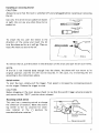
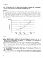
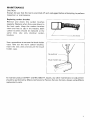
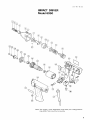
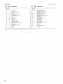
Impact Driver
MODEL 6950
Equipped with Electric Brake
INSTRUCTION MANUAL
DOUBLE
INSULAT I0 N
SPECIFICAT10NS
Capacities
Machine screw
4mm
(5132"
~
~
8mm
5116")
Impacts per minute
0
3,000
Standard bolt
6mm
(7132"
~
~
12"
112")
Hiqh tensile bolt
6 m m - 12"
(7132" - 112")
Max. fastening torque
Dimensions
(L x W x HI
1,000 kg cm
(72 4 f t Ibs)
239 mm x 60 mm x 185 mm
(9-318" x 2-318" x 7-114")
* Manufacturer reserves the right t o change specifications without notice.
* Note: Specifications may differ from country t o country.
WARNING: For your personal safety, READ and UNDERSTAND before using
SAVE THESE INSTRUCTIONS FOR FUTURE REFERENCE.
No load speed
(RPM)
0 - 2,200
Net weight
kg ( 2 , 8 ,bs,
IMPORTANT
SAFETY INSTRUCTIONS
(For All Tools)
WARNING: WHEN USING ELECTRIC TOOLS, BASIC SAFETY
PRECAUTIONS SHOULD ALWAYS BE FOLLOWED TO REDUCE
THE RISK OF FIRE, ELECTRIC SHOCK, AND PERSONAL
INJURY, INCLUDING THE FOLLOWING:
READ ALL INSTRUCTIONS.
1. KEEP WORK AREA CLEAN. Cluttered areas and benches invite injuries.
2. CONSIDER WORK AREA ENVIRONMENT. Don't use power tools in damp
or wet locations. Keep work area well lit. Don't expose power tools t o rain.
Don't use tool in presence of flammable liquids or gases.
3. KEEP CHILDREN AWAY. All visitors should be kept away from work area.
Don't let visitors contact tool or extension cord.
4.STORE IDLE TOOLS. When not in use, tools should be stored in dry, and high
or locked-up place - out of reach of children.
5. DON'T FORCE TOOL. It will do the job better and safer at the rate for which
it was intended.
6. USE RIGHT TOOL. Don't force small tool or attachment t o do the job of a
heavy-duty tool. Don't use tool for purpose not intended; for example, don't
use circular saw for cutting tree limbs or logs.
7 . DRESS PROPERLY. Don't wear loose clothing or jewelry. They can be caught
in moving parts. Rubber gloves and non-skid footwear are recommended
when working outdoors. Wear protective hair covering t o contain long hair.
8 . USE SAFETY GLASSES. Also use face or dust mask if cutting operation is
dusty.
9. DON'T ABUSE CORD. Never carry tool by cord or yank it to disconnect from
receptacle. Keep cord from heat, oil, and sharp edges.
IO. SECURE WORK. Use clamps or a vise to hold work. It's safer than using
your hand and it frees both hands to operate tool.
11. DON'T OVERREACH. Keep proper footing and balance at all times.
12. MAINTAIN TOOLS WITH CARE. Keep tools sharp and clean for better and
safer performance. Follow instructions for lubricating and changing accessories. Inspect tool cords periodically and if damaged, have repaired by authorized service facility. Inspect extension cords periodically and replace if
damaged. Keep handles dry, clean, and free from oil and grease.
13. DISCONNECT TOOLS. When not in use, before servicing, and when changing accessories, such as blades, bits, cutters.
2
14. REMOVE ADJUSTING KEYS AND WRENCHES. Form habit of checking to
see that keys and adjusting wrenches are removed from tool before turning
it on.
15. AVOID UNINTENTIONAL STARTING. Don't carry tool with finger on switch.
Be sure switch is OFF when plugging in.
16. EXTENSION CORDS. Make sure your extension cord is in good condition.
When using an extension cord, be sure to use one heavy enough to carry
the current your product will draw. An undersized cord will cause a drop
in line voltage resulting in loss of power and overheating. Table 1 shows the
correct size to use depending on cord length and nameplate ampere rating.
If in doubt, use the next heavier gage. The smaller the gage number, the
heavier the cord.
TABLE 1 MINIMUM GAGE FOR CORD SETS
Total Length of Cord in Feet
0-25
I
26 - 50
Ampere Rating
More
Not More
Than
Than
0
6
10
12
~
~
6
10
12
16
I
51 - 100
I
101 - 150
I
14
12
12
A W G
18
18
16
14
16
16
16
12
;:
14
Not Recommended
3
VOLTAGE WARNING: Before connecting the tool to a power source (receptacle,
outlet, etc.) be sure the voltage supplied is the same as that specified on the
nameplate of the tool. A power source with voltage greater than that specified
for the tool can result in SERIOUS INJURY to the user - as well as damage to
the tool. If in doubt, DO NOT PLUG IN THE TOOL. Using a power source with
voltage less than the nameplate rating is harmful t o the motor.
ADDITIONAL SAFETY RULES
1. Wear ear protectors.
2. Hold the tool firmly.
3.Always be sure you have a firm footing.
Be sure no one is below when using the tool in high locations.
4. When driving into walls, floors or wherever ”live” electrical wires may be
encountered, DO NOT TOUCH ANY METAL PARTS OF THE TOOL!
Hold the tool only by the insulated grasping surfaces to prevent electric shock
if you drive into a “live” wire.
SAVE THESE INSTRUCTIONS.
4
Installing or removing the bit
CAUTION :
Always be sure that the tool i s switched off and unplugged before installing or removing
the bit.
a6
Use only the driver bit or socket bit shown
Do not use any other driver bit or
socket bit.
a t right.
9 m m (3/8“)
To install the bit, pull the sleeve in the
direction of the arrow and insert the bit
into the sleeve as far as it will go. Then release the sleeve t o secure the bit.
I
Bit
ISleeve
To remove the bit, pull the sleeve in the direction of the arrow and pull the bit out firmly.
NOTE :
If the bit is not inserted deep enough into the sleeve, the sleeve will not return to i t s
original position and the bit will not be secured. In this case, try re-inserting the bit
according to the instructions above.
Switch action
To start the tool, simply pull the trigger. Tool speed i s increased by increasing pressure
on the trigger. Release the trigger t o stop.
CAUTION:
Before plugging in the tool, always check t o see that the switch trigger actuates properly
and returns to the “OFF” position when released.
Reversing switch action
This tool has a reversing switch to change
the direction of rotation. Move the reversing switch to the
position for clockwise rotation or the
position for
counterclockwise rotation.
0
c
__Clockwise
0
Counterclockwise
rotation
Reversing switch
5
CAUTION:
Always check the direction of rotation before operation.
0
*Use the reversing switch only after the tool comes to a complete stop. Changing the
direction of rotation before the tool stops may damage the tool.
Operation
Place the point of the driver bit in the screw head. Apply forward pressure t o the tool to
the extent that the bit will not slip off the screw. Start the tool slowly and then increase
the speed gradually. Release the trigger just as the screw bottoms out. The proper fastening torque differs depending upon the kind or size of screws/bolts, the type of materials
to be fastened, etc. Refer to the figure below for the relation between fastening time and
wood screw size.
Material to be fastend: Lauan
Seconds
6
5
1
I
0
I
03.8
x 50
I
04.0
x65
I
04.2
x90
I
04.5
x120
mm
Wood screw / Lag screw size
NOTE :
Use the proper bit for the head of the screw/bolt that you wish to use.
.When fastening machine screws in a steel plate, the proper fastening torque can be
obtained in an extremely short time (approx. 0.1 - 0.2 seconds). Turn the tool off as
soon as the impact sound i s heard.
0 Hold the tool pointed straight a t the screw or the screw and/or bit may be damaged.
0
.When driving wood screws, predrill pilot holes to make driving easier and t o prevent
splitting of the workpiece. The pilot holes should be slightly smaller than the wood
screws in diameter.
.The size of wood screw which can be fastened with this tool may differ depending upon
the type of material to be fastened. Always perform a test operation t o determine the
size of wood screw.
.When fastening bolts or nuts, always perform a t e s t operation to verify the adequate
fastening time for your bolt or nut. Excessive fastening torque may damage the bolt/nut
or socket bit.
6
MAINTENANCE
CAUTION:
Always be sure that the tool is switched off and unplugged before attempting t o perform
inspection or maintenance.
Replacing carbon brushes
Remove and check the carbon brushes
regularly. Replace when they wear down to
the limit mark. Keep the carbon brushes
clean and free to slip in the holders. Both
carbon brushes should be replaced at the
same time. Use only identical carbon
brushes.
lL
Limit mark
Use a screwdriver to remove the brush holder
caps. Take out the worn carbon brushes,
insert the new ones and secure the brush
holder caps.
To maintain product SAFETY and RELIABILITY, repairs, any other maintenance or adjustment
should be performed by Makita Authorized or Factory Service Centers, always using Makita
replacement parts.
7
ACCESSORIES
CAUTION:
These accessories or attachments are recommended for use w i t h your Makita tool specified in this
manual. The use of any other accessories or attachments might present a risk of injury t o persons.
The accessories or attachments should be used only in the proper and intended manner.
Bits
8
June-06-'95
US
IMPACT DRIVER
Model 6950
w
Note: The switch, noise suppressor and other part configurations
may differ from country to country.
9
MODEL 6950
'i,'o" AtD
June-06-'95
DESCRIPTION
MACHINE
D:$
DESCRIPTION
MACHINE
~
~
1
2
3
4
5
6
1
8
9
10
11
12
13
14
15
16
17
19
20
21
1
1
1
1
1
4
1
1
2
1
24
1
1
1
1
1
9
1
1
1
-
Ring Spring 11
Flat Washer 12
Compression Spring 13
Sleeve
Hammer Case
Tapping Screw BT4x20
Nylon Washer 14
Anvil
Steel Ball 5 6
Hamme,
Steel Ball 3 5
Flat Washer 22
Compression Spring 24
Spindle Complete
Houamg Set (With Item 34)
Name Plate
Tapping Screw BT4x20
Holder Arm
Switch
Field
22
23
1
1
24
25
26
27
28
29
30
31
32
33
34
35
36
37
38
39
1
1
1
1
1
1
1
1
2
1
1
2
1
1
2
1
Note The switch and other part specifications may differ from country to country
10
Ball Bearing 607LB
ARMATURE ASSEMBLY
(With Item 22 2 4 & 251
Fan 48
Ball Bearing 6OBLLB
Rubber Pin 4
Bearing Case IWiIh Item 261
Flat Washer 4
Gear Complete 9 34
Flat Washer 5
Plane Bearing 5
Steel Ball 3 5
Makita Label
Housing Set IWith Item 151
Carbon Brush
Switch
Cord
Brush Holder Cap
Dust Cover
1
US
P
.... . ..--.
.-.
. .
--
7
I
MAKITA LIMITED ONE YEAR WARRANTY
Warranty Policy
Every Makita tool is thoroughly inspected and tested before leaving the factory. It is warranted to
be free of defects from workmanship and materials for the period of ONE YEAR from the date of
original purchase. Should any trouble develop during this one-year period, return the COMPLETE
tool, freight prepaid, to one of Makita’s Factory or Authorized Service Centers. If inspection shows
the trouble is caused by defective workmanship or material, Makita will repair (or at our option,
replace) without charge.
This Warranty does not apply where:
repairs have been made or attempted by others:
0 repairs are required because of normal wear and tear:
0 The tool has been abused, misused or improperly maintained;
alterations have been made to the tool.
IN NO EVENT SHALL MAKITA BE LIABLE FOR ANY INDIRECT, INCIDENTAL OR CONSEQUENTIAL DAMAGES FROM THE SALE OR USE OF THE PRODUCT. THIS DISCLAIMER
APPLIES BOTH DURING AND AFTER THE TERM O F THIS WARRANTY.
MAKITA DISCLAIMS LIABILITY FOR ANY IMPLIED WARRANTIES, INCLUDING IMPLIED
WARRANTIES O F “MERCHANTABILITY” AND “FITNESS FOR A SPECIFIC PURPOSE,”
AFTER THE ONE-YEAR TERM OF THIS WARRANTY.
This Warranty gives you specific legal rights, and you may also have other rights which vary from
state to state. Some states d o not allow the exclusion or limitation of incidental or consequential
damages, so the above limitation or exclusion may not apply to you. Some states do not allow
limitation o n how long an implied warranty lasts, so the above limitation may not apply to you.
Makita Corporation
3-11-8,Sumiyoshi-cho,
Anjo, Aichi 446 Japan
884002-064
PRINTED IN JAPAN
1995 - 7 - N