1
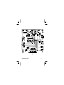
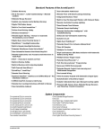
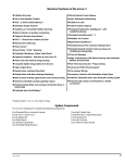
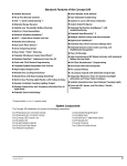
For the latest vehicle wiring
information and for wiring diagrams
and servicing information on older
Clifford products 24-hour dealer
website:
www.clifforddealer.com
USA Toll Free Technical Support:
800-444-4667
UK Technical Support Free Phone:
800-526708
Standard Features of GP500
Note: The system current draw of GP500 is 5mA plus or
minus 0.5mA. Voltage operating range is 9V to 16V.
❑ Lifetime Warranty
❑ EC 97/24 Approved
❑ Weather Resistant
❑ Two ACG™ 2 Remote Controls
❑ Extended Range
❑ Built-In Two-Point Immobilizer™
❑ Helmet Theft Protection System
❑ Fully Adjustable Dual-Level Piezo Sensor™
❑ Digital Dual-Zone Tilt/Motion Sensor
❑ Self-Powered Siren with Key Override
❑ Built-In Indicator Light Flasher with On-Board Relay
❑ User-Selectable AutoArming™
❑ Advanced CMOS Microcomputer
Installation Manual/499
1
Standard Features of GP500 (Cont’d)
❑ BikeBeacon™ Vehicle Locator System
❑ FACT—False Alarm Control and Test
❑ Patented SmartPowerUp™ 2
❑ Patented Smart AutoTesting™
❑ Five-Event TotalRecall™
❑ Remote Panic
❑ Patented Smart Prior Security Breach Alert
❑ Multiple-Vehicle Control
❑ Patented Remote Control Code Learning
❑ High-Luminescence LED with Automatic
Battery-Saving Mode
❑ All Black Wiring
2
GP500
System Connections
Control Unit
The GP500 control unit must be installed as far away
as possible from the engine. Under no circumstances
should the unit be installed close to hot or moving
parts.
1. Remove the seat and any side panels necessary to expose the
battery terminals, indicator light wiring and ignition wires.
2. Select a location under the seat to mount the GP500 control
unit. The control unit must be mounted in a flat and level
position with the side bearing the Clifford logo facing upward.
This location must stay dry and allow the use of screws or tie
wraps to securely fasten the control unit to metal. Avoid hot or
moving parts.
3. Mount the GP500 control unit using screws or tie wraps, but do
not permanently affix it until all wiring and testing is complete.
Installation Manual/499
3
LED Status Indicator
Select a prominent location on the motorcycle that is highly visible
from all directions. Discuss placement with the owner.
1. Verify there is adequate space to accommodate the LED, then
drill a 4mm (#21 drill bit) hole and route the wires through it.
2. Mate the BLACK wire connector labeled LED (+) to the LED’s
VIOLET wire as shown in the diagram on page 5.
3. Mate the BLACK wire labeled LED (-) to the LED’s BLACK
wire as shown in the diagram on page 5.
4. Press the LED into place.
PlainView 2 Coded Programming Switch
1. Discuss placement of the switch with the vehicle owner and
avoid placing the switch where it can be pressed accidentally.
2. Mount the switch on to a clean, dry surface using the supplied
adhesive tape.
3. Mate the switch’s locking connectors to the locking connector from
the control unit.
4
GP500
Installation Manual/499
5
Indicator Lights
1. Connect a voltmeter lead to ground.
2. Access the indicator light harness near the indicator light switch,
and turn on the left indicator light.
3. Probe the wires. When you probe the correct left indicator light
wire, the voltmeter will read +12V when the indicator lights
illuminate, and 0 volts when they turn off.
4. Turn on the right indicator light and repeat step 3.
5. Connect one of the two BLACK wires labeled Indicator Light
+12V to the left indicator light circuit and the other wire labeled
Indicator Light +12V to the right circuit as shown in the
illustration on page 5.
Starter and Ignition Immobilization Circuits
1. Locate the ignition switch wireloom under the gauges or
key/ignition switch and use a voltmeter to locate the one wire
that carries +12V throughout BOTH the cranking AND
engine running cycles, and 0 volts when the ignition is off.
2. Start the engine, then cut the ignition wire. The engine should
stop running.
3. As shown on page 5, connect the BLACK wire with the Ignition
Input +12 Volts label to the key side of the cut ignition line.
6
GP500
4. Connect the BLACK wire with the Ignition Output +12 Volts
label to the coil side of the cut ignition line.
5. Use a voltmeter to locate the one wire that carries +12V during
the cranking cycle ONLY. Cut this wire, then try to start the
engine. It should not crank.
6. Connect the BLACK wire with the Starter Input +12 Volts label
to the key side of the cut starter line.
7. Connect the BLACK wire with the Starter Output +12 Volts
label to the starter side of the cut starter line.
NOTE: The starter cir cuit may carry a very high
current. Be certain that the starter wire connections
are solid. Each immobilization circuit can carry 15
amps.
8. Remove the labels from each of the wires.
Self-Powered Siren with External Key Override
If a thief disconnects power and/or cuts any or all of the wires while
the system is armed, the siren will sound for five minutes and then
reset. If power must be disconnected for servicing, an override key is
provided to turn the siren off. Unlike other back-up battery sirens
Installation Manual/499
7
that constantly drain the vehicle battery, Clifford’s design draws
charging current only when the ignition is on (i.e., engine running).
NOTE: The motorcycle must be ridden for eight hours
af ter the si ren has been in stalled in or der to
sufficiently charge the siren’s back-up battery.
1. Select a location for the siren under the seat or behind a side
cover. Keep the siren away from direct exposure to rain and
moisture. Avoid hot or moving parts. Also make sure there is
sufficient clearance for the mounting screws behind the
mounting surface.
2. You must firmly secure the siren using all three sheet metal
screws supplied. Mount the siren away from areas of water ingress
or excessive heat. Point the siren down to avoid moisture.
3. Connect the siren’s BROWN wire to the BLACK wire labeled
Siren Output (-).
4. Connect the siren’s BLUE wire to the BLACK wire labeled
Ignition Output +12V.
5. Connect the RED wire to the 5 amp fuse connected to the
battery positive cable clamp.
6. Connect the BLACK wire to ground.
8
GP500
Final Wiring Connections
1. Connect the BLACK wire labeled Constant +12V 5A to the 5-amp
fuseholder as shown on page 5.
2. Connect the BLACK wire labeled Constant +12V 10A to the
10-amp fuseholder as shown on page 5.
3. Attach the two fuseholders to the constant +12V source at the
fuse panel, battery or ignition harness.
4. Use ring connectors to attach the two different BLACK wireloom
wires (labeled ground) to two different chassis ground points or
one of them directly to the vehicle fuse panel ground. The
ground points must be very clean. A factory bolt that has been
completely cleaned with a wire brush is recommended.
NOTE: Power and test accessories after the basic
sys tem has been tested. In di vidu ally fuse all
accessory power connections. Individually fuse all
+12V fuse panel connections.
Installation Manual/499
9
SmartPowerUp™ 2
SmartPowerUp 2 ensures that the system powers up in the same state
(disarmed, armed or valet mode) it was last in. When you first power up
the system, it will silently enter its disarmed state.
Remote Control Operation
To transmit either channel 1, 2, or 3: Just press either button I, II,
III, respectively. For instance, to transmit channel 3, press button III.
Refer to the GP500 Owner’s Manual for more information on how to
use the remote controls.
Remote Control Channel Assignments
Function
Press
button(s)
Arm or disarm
I
Silently arm or disarm
II
10
GP500
Function
Press
button(s)
Instant AutoArming Bypass (press and hold button for three
seconds while system is disarmed)
III
Dual-Level Piezo Sensor Warning Level Bypass (press button
after arming the system). System provides four flashes.
III
Dual-Level Piezo Sensor Total Bypass (press and hold button
for three seconds after arming the system). 7 flashes are
provided.
III
Unassigned - This button can be assigned to control ACG-2
systems and accessories on other Clifford-equipped vehicles.
I + II
Unassigned - This button can be assigned to control ACG-2
systems and accessories on other Clifford-equipped vehicles.
I + III
Digital Tilt/Motion Sensor Warning Zone Bypass (press buttons
after system is armed). 4 flashes are provided.
II + III
Digital Tilt/Motion Sensor Total Bypass (press and hold buttons
for three seconds after system is armed). 7 flashes are
provided.
II + III
Installation Manual/499
11
Function
Press
button(s)
Dual-Level Piezo Sensor Adjustment (press and hold buttons
for three seconds while system is disarmed and ignition is
OFF). See Owners Manual for complete instructions.
II + III
FACT—False Alarm Control and Test
The system microprocessor automatically checks for another
activated sensor or trigger before sounding the siren a second time,
thus preventing any further false alarms. If you wish to test FACT,
simply,
1. Arm the system with the remote control.
2. Wait 15 seconds for the Piezo sensor to become active, then
trigger the Dual-Level Piezo Sensor to activate the siren.
3. Do not disarm the system, let the siren complete its cycle.
4. Trigger the sensor again. The alarm should be silent.
5. Trigger the Digital Tilt/Motion Sensor (note that the alarm
should be in an armed state for at least one minute prior to
testing this sensor). The alarm should sound immediately. You
may now disarm.
12
GP500
Five-Event TotalRecall
The system’s nonvolatile memory records the identity of the last five
activated or malfunctioning triggers and sensors:
1. With the ignition off, press and hold the unmarked side of the
PlainView 2 switch.
2. Press remote control button 1 to arm the system, and then again
to disarm.
3. The LED will blink 1–5 times, pause, then blink 1–5 times, etc.
Write down the number of blinks in each cycle.
4. Refer to the chart below. The first number you wrote down was
the most recently activated trigger or sensor. The next number is
the second most recent, and so on up to as many as the last eight
activations.
LED flashes
1 flash
Meaning
Ignition switch was turned on while the system was
armed
2 flashes
Activation of Digital Tilt/Motion Sensor
3 flashes
Activation of Dual-Level Piezo Sensor
Installation Manual/499
13
LED flashes
Meaning
4 flashes
Activation of Helmet Theft Protection System
5 flashes
Normally Open Auxiliary Input (Optional Accessory such
as a seat trigger or pin switch).
5. If a sensor is often activated, decrease that sensor’s sensitivity (or
reposition the control unit, if necessary). If a certain trigger is
often activated, check the trigger wire for possible shorting.
Programmable Features
1. Refer to the Table of Programmable features below and find the
feature you wish to program. Make note of the number of times
to press the ✱ button.
2. Turn the ignition on, or start the engine (skip this step if the
engine is running).
3. Enter the factory preset valet code of “2” by pressing the marked
side twice, then press the unmarked side once. Press and hold
the ✱ button of the PlainView 2 switch for about 3 seconds until
you hear a siren chirp. Release the button. You are now in Program
mode.
14
GP500
4. Press and release the ✱ button of the PlainView 2 switch the
number of times indicated for the feature you are programming. You
will hear one chirp each time you press the ✱ button. Pause. You
will hear a succession of chirps equal to the number of times you
pressed the ✱ button. This audibly confirms your selection.
5. Perform the action, if any, in the “Secondary action” column.
6. Pause. You will hear either one or two chirps: Two chirps =
ON, one chirp = OFF (If there is a NOTE for the selected
feature, perform the actions noted).
7. You may now select another feature or exit program mode:
a. To select a different feature column, go to step 4.
b. To exit program mode, turn the ignition off (you’ll hear
three chirps, the indicator lights flash three times, and the
LED will turn off). The system will automatically exit
program mode after 60 seconds.
If you make an error, just turn off the ignition and start
again.
Installation Manual/499
15
Table of Programmable Features
Feature
AutoArming
Factory
Setting
OFF
No. of
Secondtimes to ary Action
press the
✱ button
2
-
Program
completion
confirmation
Result
1 chirp=OFF
-
2 chirps=ON
Chirps
ON
3
-
1 chirp=OFF
-
2 chirps=ON
FACT
ON
4
-
1 chirp=OFF
-
2 chirps=ON
Siren
Duration
30
Seconds
5
-
1 chirp=30
-
2 chirps=60
3 chirps=90
16
GP500
Feature
Factory
Setting
Triggers per
Cycle
3
No. of
Secondtimes to ary Action
press the
✱ button
6
-
Program
completion
confirmation
1 chirp=1
Result
-
2 chirps=2
3 chirps=3
Change PIN
code
-
7
Wait for
3 chirps
one chirp,
then enter
new PIN
code. Wait.
Enter new
PIN code
again.
Auto
Program
New Remote
-
9
Press
button I
Press
button I
again.The
system
provides 2
chirps.
Installation Manual/499
1 chirp
17
Feature
Factory
Setting
Program
ACG-2
Remote Arm/Disarm
-
10
Press
button to
be
programmed
1 chirp
Press the
button to
be
programm
ed again.
System
provides 2
chirps.
Program
ACG-2
Remote -
-
11
Wait for
one chirp,
then press
button to
be
programmed
2 chirps
-
Silent Arm
18
No. of
Secondtimes to ary Action
press the
✱ button
Program
completion
confirmation
Result
GP500
Feature
Factory
Setting
Program
ACG-2
Remote Instant
AutoArming
Bypass
-
12
Clear All
Remotes
-
15
Off
20
Passive
Immobilization
No. of
Secondtimes to ary Action
press the
✱ button
Wait for
one chirp,
then press
button to
be
programmed
Program
completion
confirmation
Result
3 chirps
-.
-
3 chirps
-
-
1 chirp - OFF
-
2 chirps - ON
System Checklist & Troubleshooting
The following checklist and troubleshooting tips will assure that you
have installed the system correctly. If the system does not react as
Installation Manual/499
19
noted, follow the troubleshooting tip(s) denoted with a black box
below that item, then repeat the step. Each successive step requires
that the previous step has been completed as indicated.
1. Arm the system. The following should occur:
■ The siren chirps twice. This is the correct response.
Proceed to the next step.
■ The siren chirps four times either immediately or 5-10
seconds after the initial two chirps. A trigger or sensor is
active. Disarm with the remote control and turn the ignition
ON. The LED will blink 1–5 times, pause, then repeat the
same number of blinks (the blink cycle repeats five times).
Refer to the following chart. If the Piezo Sensor is indicated,
check the mounting location of the control unit and the
sensitivity setting.
LED flashes
1 flash
2 flashes
20
Meaning
Ignition switch was turned on while the system was
armed
Activation of Digital Tilt/Motion Sensor
GP500
LED flashes
Meaning
3 flashes
Activation of Dual-Level Piezo Sensor
4 flashes
Activation of Helmet Theft Protection System
5 flashes
Optional Accessory (such as a seat trigger or additional
pin switch, etc.)
p No chirps. Verify that the Chirps feature (column 2, row 1)
is “On”, verify that the siren key turned to the “On”
position, and check wiring connections as noted in the
Self-Powered Siren section on page 7.
■ When you arm, the indicator lights will blink twice.
p If the indicator lights blink only once, the system had
previously AutoArmed itself passively and by pressing
button 1 the system disarmed (remote disarming is
acknowledged with one indicator light blink). Repeat step 1.
p If only the right or the left side indicator lights blink, see the
Indicator Lights section on page 6.
p If no blinks, verify the indicator light bulbs are operational.
If not, they must be replaced. If so, repeat steps 1-5 of the
Indicator Lights section on page 6.
Installation Manual/499
21
■ When you arm, the LED will blink repeatedly.
p If the LED does not blink, verify that the LED’s wires are
solidly connected to the system’s wireloom. Warning: This is
a 2-volt LED, testing with 12 volts will destroy the LED.
■ When you arm, the dual onboard Immobilization circuits will
immediately engage (test this by turning the key in the
ignition switch; the engine should neither start nor crank).
p If the engine can be started or cranked, the starter and/or
ignition immobilization circuits are miswired. Carefully
retest the vehicle wires as noted on page 6.
NOTE: If none of the above occurs when you arm the
system, then perform the following diagnostics:
p Check the power and ground connections.
p Make sure the fuses are in the fuseholders.
p Verify that the control unit connectors are properly inserted
into the control unit.
p Verify that the ignition input and output wires are
connected to a true ignition line. Find the true ignition line
by following steps 1-4 of the Starter and Ignition
Immobilization Circuits section on page 6.
22
GP500
p Verify that the transmitters are programmed correctly.
■ NOTE: If the 10-amp fuse blows upon arming:
p Disconnect the system’s two indicator light wires, replace
the 10-amp fuse and re-arm. If the fuse does not blow, one
(or both) of the vehicle’s indicator light wires is shorting.
Find and correct the short(s), reconnect the indicator light
wires, then rearm.
3. Disarm by pressing remote control button 1. The following
should occur:
■ The siren chirps once.
■ The indicator lights blink once.
■ The LED turns off.
■ The Immobilization circuits immediately disengage (test this
by turning the key in the ignition switch; the engine should
crank, start and idle normally).
4. Test remote control range by standing approximately 20 feet from
the motorcycle and use the remote control to arm and disarm the
system.
■ The system will respond with the previously noted indications
for arming and disarming. If not:
Installation Manual/499
23
p Reposition the control unit as far as possible from heavy
wirelooms and metal.
p Verify that the remote control battery measures at least 3
volts while transmitting.
p Verify the voltage at the control unit between the 5-amp
fused power line and each of the two ground lines measures
at least 12.0 volts (if less, make sure both chassis grounds
are solid; if the grounds are solid, the vehicle battery may
need charging, servicing or replacement).
24
GP500
Installation Manual/499
25
USA Headquarters:
Clifford Electronics, Inc. 20750 Lassen Street, Chatsworth, CA 91311
Within USA: 1-800-824-3208
Phone: (818) 709-7551 Fax: (818)407-1743
All Clifford systems are covered by
one or more of the following Clifford Electronics USA
patents:
4,158,874; 4,233,642; 4,327,444; 4,383,242; 4,430,685;
4,845,464; 4,887,064; 4,890,108; 4,922,224; 4,997,053;
5,081,667; 5,146,215; 5,157,375; 5,467,070; 5,650,744
and other patents pending.
© Copyright Clifford Electronics, Inc., 1999
26
32-840B/USGPIM/399
GP500