1
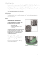
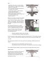
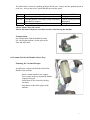
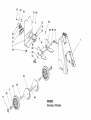
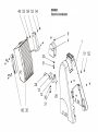
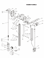
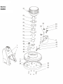
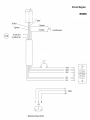
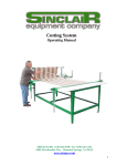
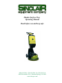
Mambo Surface Prep
Operating Manual
Read before use and keep safe
(800) 624-2408 (530) 626-9386 Fax (530) 626-5144
6686 Merchandise Way Diamond Springs, Ca 95619
www.sineqco.com
Table of Contents
1.0
Technical Data
Page 3
2.0
Safety
Page 3
3.0
Safety Instructions
Page 3
4.0
Maintenance
Page 5
5.0
Use
Page 7
6.0
Vacuum Unit
Page 7
7.0
Trouble Shooting
Page 8
8.0
Spare Parts/Schematics
Page 9
2
1.0 Technical data/technical description
Power supply
Power consumption
No-load speed
Sound pressure level
Sound energy level
Hand/Arm-Vibration
Weight
110V 50 Hz
2300W
100 – 400 Strokes/min
56 dB(A)
69 dB(A)
< 4,5 m/s²
155 lbs
Comes with:
Mambo Surface Prep, safety goggles and tool kit.
2.0 Safety
The Sinclair Mambo Surface Prep is state of the art designed and meets all
standard safety requirements.
3.0 Safety Instructions
Disconnect the power supply before any maintenance is carried out. Use only recommended
mounting discs and brushes. The mounting discs must have a plain surface. Use only genuine
Sinclair discs and brushes. Other parts could affect the safety of the machine.
Always use the safety – and suction ring.
Otherwise parts of the sub-floor may be
cast out and endanger other persons.
Always lock the additional weight with the
screw nuts. Use only the genuine Sinclair
weight. DO NOT USE ANY OTHER
WEIGHTS!
Maintenance should be undertaken only by
qualified personnel. Use only genuine
Sinclair parts.
Use only appropriate detergent liquids.
Check the power cord and the plug before
starting. Both of them must be in perfect
condition, the insulation must not be damaged.
Have damaged insulation repaired at once,
before starting the machine.
Otherwise this may result in considerable
danger to the user.
Speed Control
3
For your won safety start work always at low speed, and then increase the speed. This is
especially important, if the sub-floor condition or the discs used are not well known.
CAUTION!!! Always wear ear and eye protectors! CAUTION!!!
Using this machine without ear and eye protectors may jeopardize or harm your health.
It may harm especially your ears and increase the risk of an accident.
The user and any person within range should always use ear protectors!
PLEASE READ DETAILED SAFETY INSTRUCTIONS ON COLORED
SHEET BEFORE USING MACHINE!
3.1 Introduction
This operating manual should be used to receive the maximum benefit from your Mambo
Surface Prep. Following these instructions will both extend the life of your machine and
reduce repair costs.
Please ensure that any user of the machine is familiar with these instructions before work
begins.
3.2 Danger while working with the machine
The Mambo Surface Prep is designed to the highest technical standards. Incorrect use can be
dangerous!
Use this machine only:
- As instructed in this operating manual.
- With the machine in perfect working order.
Disturbances that could impair safety have to be eliminated at once.
3.3 Restriction of use
The Mambo Surface Prep is exclusively for wet-cleaning and polishing of resilient and textile
floor coverings, and for grinding and milling pavement and leveling compounds in dry
environments. It should not be used for any other purpose. Sinclair Equipment Company
cannot be held responsible for any damage or loss caused by incorrect use.
4
3.4 Genuine Spare Parts
Spare parts and accessories are manufactured uniquely for the Mambo Surface Prep. It must be
emphasized that parts obtained from unauthorized sources must not be used.
Sinclair Equipment Company cannot be held responsible for the performance of or any damage
arising from the use of machines in which genuine spare parts have not been used.
This is particularly important with milling discs.
4.0 Maintenance
The Mambo Surface Prep is virtually maintenance free. The roller bearings and gear box
need not be lubricated.
5.0 Use
Inserting the safety and suction ring
Lay the machine down on the handle. Thus
the support of the discs is accessible.
-
Insert safety ring
Mount at once a disc to fix the
suction ring
Assembly of mounting discs, pads and brushes
Lay the machine down on the handle. Thus
the support of the discs is accessible. Put the
mounting disc on the actuation and lock it
by turning anti-clockwise.
Mounting the additional weight
Always lock the additional weight with the
screw nuts. Use only the genuine Sinclair
weight.
Do not use any other weights! This may
overstress the machine.
5
Use:
- Mount discs or brushes as described above.
- Put the handle in working position with the
big lever (1) at the back.
- We recommend to position the hand grip to
the height of the users hip.
- Lift the handle slightly, to make sure the
machine stands horizontally.
- Keep the safety switch (2) pressed.
- Switch on the machine with one of the levers
(3) located beneath the grip.
- Release switch (2).
Note: lever can only be actuated, if the handle
is not in vertical position. This is a safety
feature! The user cannot control the machine
with the vertical handle. After switching on
the machine, the handle will move shortly to
the right.
If the transportation wheels are in lifted
position, the direction in which the machine
moves, is controlled by lifting or lowering
the grip. The more you lift or lower the
grip, the faster the machine runs to the
corresponding direction.
-
Lifting the machine: machine runs to the right.
Lowering the machine: machine runs to the left.
If you feel unsafe or cannot control the machine, just release lever (3). The machine will stop
at once. If you have carried out some training, you will be able to operate the machine with
one hand.
If the transportation wheels are lowered to the floor, the machine is stabilized and easier to
control.
-
Lifting and lowering of the handle is no more necessary.
The machine has to be in a level position. The wheels have to be fixed accordingly.
By loosening the release handle (5), the wheels can be put in upper and lowered position.
Speed control:
Adjust the speed of the discs with switch (4).
Turning clock-wise increases the speed,
turning anti-clockwise decreases the speed.
The optimal speed is dependent on the disc
used and the sub-floor.
6
The table below is meant as a guiding principle for the user. Always test the optimum speed in
each case. Always start at low speed and then increase the speed.
Speed
160–200
200-300
300-400
Use
Grinding screed and leveling compounds
Grinding parquet, removing leveling compounds
and adhesive residues
Removing leveling compounds
Recommended Disc
Sand paper
Carbide grinding disc and
Milling disc
Milling disc
Always remove discs after work.
Always disconnect the power cord after work or when leaving the machine.
Transportation
For transportation, fold the handle forwards.
For carrying the machine, use the grips at the
front and at the back.
6.0 Vacuum Unit for the Mambo Surface Prep
Mounting the Vacuum Micropac
Assemble the vacuum unit from the front of the
Handle of the machine.
- Insert vacuum into the lower support
- Turn vacuum at the top against the handle.
Engage fixing pin.
- Fasten hose to the vacuum by turning
clockwise.
- Attach hose to the outlet spigot of the
machine.
7
Mounting or changing the paper bags of the Vacuum Micropac Unit
Paper bags are used for the vacuum unit Micropac.
Replacement paper bags, 20 piece, Item # M13498.
-
-
Release the 2 snap fasteners (B) and
remove lid (C).
Ensure inner cloth filter is clean.
Ensure rubber molding (D) is firmly
fitted around top rim of container.
Gently open new dust bag and place in
vacuum container. Slide flange (A) of
the dust bag over inlet spigot (E) until
secure.
Replace and secure lid with 2 snap
fasteners.
To facilitate the removal of a full dust bag, tube (E) may be withdrawn from the
vacuum unit container having firstly removed elbow connector (F).
7.0 Troubleshooting
Trouble
Machine does not start
Switch-on lever cannot be
actuated
Machine stops
Eventual Cause
Power supply disconnected
Blown fuse
Defective cable or plug
Safety lever can only be actuated,
if handle not vertical
Lamp flashes fast
Overload protection responds
Elimination
Have a machine repaired by
a qualified electrician,
resp. change parts
Lower the handle of the
machine
Power plug disconnect
Wait some minutes
Switch the machine on again
8.0 Schematic/Parts List
Schematic #
1
2
Pieces
1
1
Description
Housing
Disc cover
Part #
017830
037933
8
3
4
5
6
7
8
9
10
11
12
13
14
15
16
17
18
19
20
21
22
23
24
25
26
27
28
29
30
31
32
33
34
35
36
37
43
45
46
49
50
51
52
53
54
55
56
57
58
59
61
64
65
66
1
1
1
1
2
2
2
2
1
1
1
1
1
3
2
2
1
4
2
4
4
1
2
2
2
2
2
2
2
1
1
1
1
2
3
1
1
1
9
6
7
4
13
4
2
2
2
2
1
1
1
2
2
Back panel
Support chain wheel
Handle support
Additional weight
Cylindrical screw M10 x 70
Wheel hub
Square nut
Counter Sink Screw M8 x 14
Cylindrical screw M4 x 12
Lever (handle adjustment)
Handle mounting
Chain wheel
Recessed grip
Oval head screw M4 x 10
Split pin
Thumb nut
Power socket
Washer
Wheel
Counter Sink Screw M4 x 16
Hexagon nut
Counter sunk screw M8 x 50
Cylindrical screw M3 x 30
Stop nut
Washer
Hexagon nut
Dowel pin
Washer M8
Hexagon bolt
Rubber washer
Motor
Chassis
Electronics
Handle
Cylindrical screw M8x20
Cable
Axle
Chassis
Cylindrical screw M6 x 20
Stop nut M6
Washer
Cap nut M6
Washer M6
Tallow-drop screw
Washer
Cylindrical screw M10 x 20
Washer M10
Locking screw M10 x 80
Holding device electronics
Cylindrical screw M6 x 25
Cache
Nut M10
Cylindrical screw M8 x 25
037935
017872
015404
038311
018298
017922
017605
017698
018284
014648
017925
016922
017594
014804
014888
016995
014653
017637
014645
017702
014831
017631
017744
017768
014829
014817
018058
014860
014775
018624
037293
037957
038287
037940
014734
037956
037967
037958
014730
014815
014827
017728
014859
017680
018236
018301
014861
014789
037963 or 037962
014731
016138
038290
014735
9
67
68
69
70
71
72
73
74
75
76
77
78
79
80
150
152
153
154
155
156
157
158
160
161
162
165
167
168
169
170
172
173
175
176
178
179
181
185
187
188
190
191
193
194
195
196
197
198
8
1
4
2
2
2
1
1
1
6
1
3
12
3
1
1
1
1
1
1
1
1
6
1
2
2
1
1
2
2
2
1
4
1
1
1
2
2
2
2
2
1
1
4
4
1
1
1
Screw 5/16"
Plate
Cylindrical screw M4 x 20
Connection
Handle
Clamping lever
Intermediate flange
Upper flange
Lower flange
Cache
Coupling flange
Distance washer
Counter sunk screw M8 x 12
Counter sunk screw M8 x 18
Knob
Two-hand switch
Lever
Base support
Switch housing
Press plate
Foam grip
Counter sink screw
Square nut
Fixing pin
Clamp socket
Cable hanger
Towing bar
Spring (handle adjustment)
Starlock head D8
Cylindrical screw M8 x 40
Counter sink screw M8 x 18
Profile rod
Washer
Headless Pin M8 x 30
Potentiometer
Control wire
Cylindrical screw M4 x 8
Hexagon nut M8
Washer
Cap nut M8
Headless Pin M8 x 35
Cable pit
Cylindrical screw M4 x 55
Cable clamp
Oval head screw M4 x 25
Hexagon nut M10
LED lamp
Wiring
037936
038502
017725
038285
037954
037952
037966
037965
037964
037951
015401
015402
038423
014759
014647
015000
017894
017858
017875
017901
015421
017632
017605
015406
015431
015427
017592
014898
014880
014738
014759
017843
014828
017523
014650
038032
017473
014810
017663
014825
014790
038289
017639
017680
017680
017013
038281
039006
STANDARD WARRANTY
10
MAMBO HANDLE
SINCLAIR EQUIPMENT COMPANY’S tools are warranted to be free of defects in workmanship and
materials for a period of one year from the date of original purchase. Should any trouble develop during
this one year period, return the complete tool, freight prepaid, to SINCLAIR’S authorized Service Center.
If inspection shows the trouble is caused by defective workmanship or materials, SINCLAIR
EQUIPMENT COMPANY will repair, or, at its option, replace without charge.
•
This warranty does not apply to malfunctions caused by damage, unreasonable use, faulty repairs
made by others, or failure to provide recommended maintenance.
•
The warranty is void if the product is altered by the original consumer purchaser, or if it is used in a
manner not recommended by the manufacturer.
•
The warranties do not cover consequential damages or transportation charges incurred with the
replacement or repair of SINCLAIR EQUIPMENT COMPANY products.
•
Not responsible for lost job or down time.
In no event shall SINCLAIR be liable for any indirect, incidental, or consequential damages from the sale
or use of the product. This disclaimer applies both during and after the term of this warranty.
SINCLAIR EQUIPMENT COMPANY disclaims liability for any implied warranties, including implied
warranties of “merchantability” and “fitness for a specific purpose”, after the one year term of this
warranty.
This warranty gives you specific legal rights, and you may have other rights which vary from state to
state. Should you have any questions, contact SINCLAIR EQUIPMENT COMPANY at (530) 626-9386.
To obtain warranty service, deliver or send the complete tool, prepaid, to SINCLAIR EQUIPMENT
COMPANY. Be sure to include the following information:
•
•
•
•
Nature of failure;
Name and address of distributor where tool was purchased;
Application of tool when rendered defective; and
Proof of purchase.
To obtain individual repair parts, contact SINCLAIR EQUIPMENT COMPANY with the following
information:
•
•
•
Tool model number;
Item part number; and
Description of part.
11
12