1
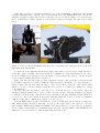
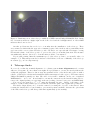
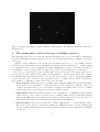
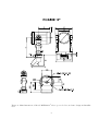
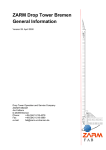
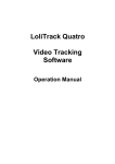
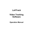
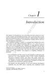
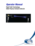
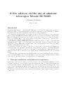
A few advices on the use of amateur
telescopes Meade RCX400
V. Kornilov, B. Safonov
May 12, 2010
Introduction
It is known that small 25 – 30 cm amateur class telescopes are used in solving many problems of
astronomy: study of variable stars, search for exoplanets, registration of optic tramsients and gammaray bursts. Very often these instruments are used in site testing campaignes.
To study the optical turbulence above planned location of the 2.5 m telescope of the SAI, 30 cm
telescope Meade RCX400 was purchased. This telescope is progressive representative of the its class.
Here we would like to present some tips on how to force such a telescope to operate in automatic
mode over long time. May be some tips are related to the specifics of this telescope, others are more
general and can be applied in different situations.
We operate a telescope at 2100 m above sea level with temperatures of down to −20◦ C and with
humidity reaching to 100% over 2 years almost every clear night. Despite recurring problems with
this telescope, about 2000 hours of measurements of the optical turbulence were carried out during
which more than 3000 pointing were made.
We will not describe the features of the telescope, they can be found in the user manual and
on different sites. We emphasize only that the developers tried to make a convenient instrument
for occasional observations. A telescope for automatic operation (without operational intervention,
with only periodic remote control) set for a long time and is constantly under the control of external
machine.
Naturally, many of the inherent features (such as a GPS receiver) seem superfluous, and, conversely,
some of the functionality you need is absent. However, we are not going to criticize the shortcomings
of the telescope and try to describe our experience in overcoming them.
1
Telescope installation and additional arrangements
Fork mount of the telescope allows you to use it in the polar or alt-azimuth installation. If the
possibility exists set the telescope in the equatorial configuration. Thus, you will greatly simplify task
of monitoring the behavior of the instrument. Do not rely on the fact that the software will correct
errors of the mount alignment. Align position of the polar axis with the greatest possible care. The
disadvantage of the polar set is some loss of stiffness due to the equatorial wedge under the mount
base. However, if it is stationary robust construction, its influence will be much less than a vibration
of the mount.
1
If the size of telescope enclosure permits the use of the alt-azimuth configuration only, install
carefully azimuthal axis to vertical. You can use striding level. Our instrument is placed in the altazimuth configuration, inside the enclosure of the size of 1.5 by 1.5 meters with a roof of cabriolet-type
made of thick fabric. In Fig. 1 (left) one can clearly see that we are using only part of the regular
tripod.
Figure 1: Telescope Meade RCX400 under the dome of automatic site testing monitor of SAI. Left:
July 2007, right: March 2008
No matter how successful the situation is, it will be impossible to avoid some problems. Therefore,
we should consider carefully controls and methods of elimination of abnormal situations. Of course,
we are not talking about emergency cases, the failure of components of the telescope, but the frequent
cases of software failures and their consequences.
Improperly laid cables from the receiving equipment can also cause problems, so they should all
be brought together in one bundle of sufficient length. It’s most convenient to tie cables and wires to
plait by plastic ties, but their tails can cling to other objects. Hence that part of the bundle which
will move one way or another during rotation the telescope have to be fasten by bonding tape or rings
of the shrink tube.
In some cases, it’s necessary to remotely power on/off the telescope. You can use either the
purchased TCP/IP switch, but we chose to make a special converter +24/+12 V (main power supply
of ASM is 24 Volts from two batteries in series) controlled by the same serial line RS232 which used
for telescope control. For software homogeneity, this unit switch the power by on and off commands
:oN# and :oF#. Other commands are passed on to the telescope.
General WEB-camera acquire a reputation for remote monitoring and resolution of emergency.
The camera installed in such a way that one can see the bigger part of the telescope. We used
quite sensitive WEB-camera Philips SPC900NC. The camera allows to see the telescope at night in
the moonlight. Additionally you can install bright remotely controlled LEDs. Such illumination is
sufficient to get a general idea of what is happening under the dome.
2
Figure 2: Visual inspection of the telescope with help of WEB-camera Philips SPC900NC. Left: during
the observations in the moonlight, right: in the dome closed and the backlight turned on. Green LED
indicates that dome is closed
Another problem was discovered for 2 - 3 months after the installation of the telescope. These
were an insects, which with the approach of autumn begun to hide in the notches, particularly in the
gap between the corrector plate and telescope tube. We had to set a special cuff of soft tissue covering
the internal volume of the telescope tube to protect the telescope from this phenomen. The measure
was sufficiently effective, the need to clean the mirrors didn’t occur anymore.
If your task permits, limit the maximum speed of the telescope axis to a reasonable value, for
example: 3◦ /s. This will prevent the breakdown of the DC motor in case of difficulty of the telescope
movement (e.g., at low temperatures).
2
Telescope finder
Do not rely on that the nominal alignment of coordinate system Auto Alignment made on stars
will serve a long time. No more than a few nights. It’s problematic to execute it remotely without the
additional equipment. Therefore throw away the standard holder of the finder and replace it with a
reliable, robust holder. On the finder install the CCD camera instead of the eyepiece. The same camera
Philips SPC900NC is suitable for this. The field of view will be sufficient: in the case of standard
RCX400 finder — 0.9◦ × 1.2◦ . It is advisable to mount the camera in a sealed metal housing. How to
remove the original packing one can found on the site ( tt http://www.robertreeves.com/900NC.htm).
You can see the stars up to 7m ÷ 8m using the maximal exposure . In Fig. 3 the image of the
Pleiades, obtained with 5 frames per second and the automatic gain control (gain=auto) is shown.
The finder design allows you to focus the camera by rotating the objective on the thread. After
focusing the lens should be secured firmly to prevent its spontaneous shifts, otherwise the optical axis
of the finder and telescope will diverge with time significantly (a few arcmin).
3
Figure 3: The Pleiades image obtained with the camera finder. The faintest star in the frame has a
magnitude 8.3m
3
The maintenance of the telescope coordinate system
The main task of the telescope mount is pointing and tracking of the object being studied. In principle,
the Meade RCX400 fork mount and its electronics execute that task, but the beginning of work is a
weak point.
Applied for the orientation of the mount level and magnetometer are good for visiting amateur
sessions, but in a stationary telescope installation is rather pointless. Setting the coordinate system
by pointing the telescope at 2-3 brightest star (Auto Alignment) provides good accuracy but only for
a few nights, because of the problem of saving of the accuracy from a shutdown to a shutdown.
Of course, you can keep the power on all the time, but even if we ignore the energy saving, it does
not solve the problem completely. Typically, for a few nights a coordinate system is lost due to failures
and mistakes in the proprietary software. Over 2 years of observations, we have consistently examined
several options for the conservation and restoration of the coordinate system. In the following list
these regimes of completion / start of the telescope are specified:
1. Park position. The Meade telescope parking using command :hP# has the following disadvantages: 1) there is no possibility to obtain information on the completion of this procedure, 2) a
common error in the telescope soft often leads to tripping-over a limiter and to loss of coordinate
system, when telescope moving in a horizontal coordinate system.
2. Sleep Mode. This feature allows to reduce power consumption to a minimum without turning
off the telescope. The regime is activated by a command :hN# and the normal functioning is
switched in :hW#. However, several times we observed, when being in sleep mode, the telescope
would suddenly begin to move with big speed and ran into the limit stop.
3. Home Position. After telescope start, the command :hF# is issued — search starting position.
The telescope is positioned on its sensors, which gives sufficient accuracy for next pointing with
the use of finder. Disadvantages are a longer duration of the procedure and the low reliability
of the level.
4
4. Default Position. In this mode, before each shutdown the telescope is set at a fixed position
which coordinates are pre-installed with the command :hS# as default. Thus, when you turn the
telescope on, it already has the correct horizontal coordinate system. To work in the equatorial
system the exact time is needed. The disadvantages are obvious: turning off the telescope in the
wrong position or a random shifting in the off state lead to loss of orientation.
The Home Position is the only method that ensures the recovery of the coordinate system,
although its accuracy is not high. Another advantage of this method is its autonomy, it doesn’t
require periodic inspection of the telescope and remote manipulation. Therefore, this method was
used for 1.5 years as basic. However, after the failure of the level sensor (due to movements in altitude
the cable connecting the level/magnetometer board with the main board was broken), we had to look
for an alternative method of orientation recovery.
It turned out that the telescope can be set to the desired starting position with an accuracy of
better than 20 − 30′ manually (by offset commands) relying on image from the dome camera. Then
the telescope shutdowns. After subsequent start, the coordinate system will be consistent with the
telescope position. This procedure is so simple and reliable, that we use it for the last few months.
Refinement of the coordinate system is called each time after a successful pointing on the measured
stars with help of the sync command :CA#. When work finished, the telescope is installed in the more
accurate starting position.
Another useful tool is a laser pointer, fixed on the telescope tube and indicating the right initial
position with help of label placed on the enclosure wall. Positioning accuracy is better than 10′ . Also
the return telescope to working position manually becomes simplier.
In principle, having the camera finder and using undocumented commands :EK...# (See next
section), one can perform the procedure Auto Alignment but we did not test this possibility.
4
Focusing and collimating
In principle the design of the focusing mechanism of telescope is a very progressive and flexible.
However, the real implementation leads to the fact that in the process of refocusing telescope optical
system is gradually coming to unadjusted state: the corrector plate (with the secondary mirror fixed
on it) become tilted. So-called secondary coma is appeared persistent throughout the field of view.
In addition the optical axes of the instrument and the finder diverge. Extra focal image is not kept
as axisymmetric. Since the DIMM device uses two off-axis entrance aperture, this coma is seen as
astigmatism in both images.
Established electronics allows to collimate the telescope, i.e. to tilt the corrector plate in two
directions in such a way that the optical axes of the mirrors coincide. This procedure requires the
presence of an observer and it is not trivial task to execute it remotely even if you can see the image
in the field of view.
However, if you use a single device as detector, you should inspect extra focal image without
violating working focus position. De-focusing of the image can be reached either by de-focusing viewer,
or by displacement of CCD camera. You must then carry out a thorough adjustment (collimation) and
remember it by the command “Collimation/Set Default” of AutostarII menu. Then the restoration of
the optimal collimation in optimal focusing position may be done with command “Collimation/Restore
Default”.
To remotely call the execution of the menu item “Collimation/Restore Default”, not having the
appropriate command in the list of remote commands, you can use an undocumented command
5
:EK...# simulating the pushing of the buttons on the telescope keypad. The buttons codes are given
in Appendix A. Assuming that pad is in initial state after power on, the sequence of the commands to
do correct collimation restoration is listed in the table. It reflects a navigation on AutostarII menu.
Table 1: The sequence of the commands to call “Collimation/Restore Default”
1
2
3
4
5
6
7
Command
Button
:EK09#
:EK09#
:EK09#
:EK13#
:EK68#
:EK68#
:EK68#
Mode
Mode
Mode
Enter
Scroll down
Scroll down
Scroll down
8
9
10
11
12
13
14
Command
Button
:EK68#
:EK68#
:EK13#
:EK68#
:EK13#
:EK68#
:EK13#
Scroll
Scroll
Enter
Scroll
Enter
Scroll
Enter
down
down
down
down
Note that it is necessary to wait for the answer to each command, i.e. pause between two commands
must be at least 2 s, and starting after the last command the recovery procedure takes not less than
1.5 min. Telescope keypad may be disconnected.
5
Dew cap
All catadioptric telescopes have a weak spot: the corrector plate is located at the top of tube and
therefore is affected by fogging due to radiative cooling under clear skies. At high ground humidity,
which is often observed at the site of the installation of our telescope in the off-season, this problem
leads to the loss of a perceptible part of the observation time.
The design of the telescope provides a heater of corrector plate, but its efficiency is very low, since
the power of the heating element is small and it is located just on the edge of corrector plate, which has
poor thermal conductivity. Having considered the various ways to mitigate of fogging, we stopped at
the classic passive dew cap. However, since the space under telescope enclosure is small, we modified
its structure.
Because the combined instrument MASS/DIMM requires not all entrance aperture but only three
sections with a diameter of about 10 cm, our dew cap consists of a metal cap, put on the front edge of
the telescope tube with three octagonal tubes diameter of 10 – 11 cm and a length 15 cm The location
of these holes and tubes selected in accordance with the MASS/DIMM input apertures geometry.
After installing such dew cap in November 2007, the fogging problem was virtually solved. This
kind of blind (see Fig. 1 is somewhat inconvenient for the adjustment of the instrument and the
telescope, so it should be easily removed and installed again.
6
6
Appendix A
Table 2: Command :EK. . . # codes, corresponding the keypad of Autostar II (The code in decimal
form, movement arrows codes could not be determined
Code
09
13
49
50
51
52
53
54
55
56
Button
MODE
ENTER
Speed (1)
Cald (2)
M (3)
Focus (4)
SS (5)
Star (6)
Ret (7)
IC (8)
Symbol
LF
CR
1
2
3
4
5
6
7
8
Code
57
63
68
71
72
85
??
??
??
??
7
Button
NGC (9)
Help
Scroll down ▽
Go To (press)
Go To (release)
Scroll up △
Arrow ⇑
Arrow ⇓
Arrow ⇐
Arrow ⇒
Symbol
9
?
D
G
H
U
–
–
–
–
Figure 4: Main dimensions of Meade RCX400 12′′ telescope, needed for enclosure design and installation
8