1
INSTRUCTION INFORMATION
PROGRAMMABLE AUDIO LINE SWITCH
G-9420
GENERAL DESCRIPTION
The Programmable Audio Line Switch
(PALS), model G-9420, allows the customer
to access devices within the substation
from a single telephone communications
line with only one call to the station. Once
the G-9420 has answered, a window of time
opens to allow direction of the call to one
of the eight ports. If the call is not directed
using DTMF tones, the G-9420 defaults to
and rings port 1 after approximately 10 seconds. When communication to a port is complete, the user may redirect the call to another port once
that device has gone on-hook. Port 1 is typically used for the handset in the station. A station
emergency requiring use of this handset disconnects all other ports when port 1, or the handset, goes
off-hook.
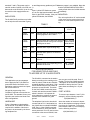
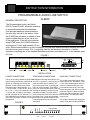
FIGURE 1
VDC
IN
ALARM
àß
+ – G
PORT 1
PORT 4
PORT 5
PORT 8
13 24
LINE IN
57 6
5V
+ –
TB1
8
INSTALLATION
POWER CONNECTIONS:
TELEPHONE CONNECTIONS:
AUXILIARY CONNECTIONS:
The top of the case is labeled to show what
All telephone lines are terminated on a 2- The G-9420 is provided with an alarm
system voltage the PALS is configured to wire, RJ-11 connector. If a 4-wire plug is relay output at TB1, terminals 4, 5 and
operate on. Note that the 125Vdc unit
used, the middle pair of contacts, usu6. This relay contact toggles when the
operates on both 125Vdc and 115Vac.
ally red and green wires, is used by the power is turned off on the unit or the
The power input is wired with the "+" or PALS for communication. The LINE IN microcontroller fails to run. This relay
"L" of ac into the "+" input on TB1, termi- jack is for connecting the PALS to the linefollows the green "ON" LED on the front
nal 1. The "-" or "N" of ac connects to the entering the building or station from the panel (see Figure 2). When operating
"-" input at TB1, terminal 2. The chassis telephone company. The other 8 RJ-11 normal, the relay contacts are closed
ground connection at TB1, terminal 3, is jacks connect the PALS to the devices in from terminal 5 to 6 and open when
very important for the protective circuitry the station. Port 1 is the recommended power is lost.
of the PALS; therefore, connect it to a veryport for the local station telephone since
good ground.
it may be programmed to interrupt all
The G-9420 internal power supply genother ports.
erates +5Vdc and is made available at
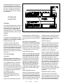
FIGURE 2
Da-Tel Research Co.
G-9420
PORTS AVAILABLE
ON
LOCALRING
OFFHOOK
RING
INDICATION
DTMF
G-9420 PROGRAMMABLE AUDIO LINE SWITCH
C.P.
ON
1
PAGE 1
2
3
4
5
January 2001
6
7
8
memory space is not available. Note also
on and diagnose any problems (see Table
terminals 7 and 8. This power may be
that the red RING INDICATION LED is
used for another G-9420 or for 5Vdc mo- 1).
merely a flash since the G-9420 answers
dems such as the G-9615A. Up to 1A may
If port 1 yellow LED flashes on power
immediately.
be used from this supply without conup, an error has been detected in the time
cern.
clock for the DTMF decoder. If the port 7 MOUNTING:
yellow LED flashes, the NVRAM
INDICATORS:
The unit may be either 19" rack-mounted
or the cover may be removed and the 4
The G-9420 PALS provides many indicainternal ¼" holes used for panel mounttors to help the user know what is going
ing.
TABLE 1
LED
LABEL
COLOR
DESCRIPTION
NORMAL
STATE
RING
Indication
Red
OFF
HOOK
Yellow
LOCAL
RING
Red
Indicates when a port is being rung.
OFF
ON
Green
Indicates when power is on and CPU
is running.
ON
PORT 1
Yellow
Indicates when port 1 is available or is
off hook.
ON - available
or off hook.
PORT 2-8
Yellow
Indicates when a corresponding port is
available or off-hook.
ON - available
or off-hook.
Indicates when an incoming ring signal
is being applied to the G-9420.
OFF
Indicates when the G-9420 has answered OFF, only ON
and gone off hook. Will go out once port
when G-9420
device goes on hook.
holds the line.
APPLICATION NOTE
FOR USING TWO G-9420 PALS
TO ACCESS UP TO 15 AUDIO PORTS
GENERAL
The G-9420 is connected to the station
battery according to the marking on the
case for polarity. With the two G-9420s
operating adjacent to each other, 5 Vdc
can be derived from the first G-9420 to
power the second G-9420. The switch
on the first G-9420 controls the power
No special programming of the
for both units and the second G-9420's
G-9420s is required to access the sec- switch is inactive. It is important for
ond G-9420. The standard, factory con- noise reduction to connect the ground
figuration was used to test these hard- terminal of the G-9420s to a good
ware configurations.
ground.
This application note encompasses
how to apply the Da-Tel G-9420 Programmable Audio Line Switch to an
application requiring more than 8 ports
but not more than 15.
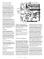
HARDWARE
Figure 3 illustrates a typical application of two Da-Tel G-9420s. All that is
required is the addition of devices to
the ports to be accessed by the incoming telephone line.
ever, any port could be used. Ports 2
through 7 on the first G-9420 and ports
1 through 8 on the second G-9420 are
available for dial-up devices. The diagram shows numbering for a 15 port
setup.
PORT ACCESS
To access a port between 1 and 7 (2 for
example), use the following sequence:
1(303)249-8919,,,2
The telephone line into the site should where the number of commas is depenconnect with an RJ-11 termination into dent on the telephone exchange connect
the G-9420 where marked INCOMING time; three is a good start. To access a
port between 8 and 15 (10 for example),
LINE. Port 1 of the G-9420 is typically
use the following sequence:
a local handset for use by the maintenance personnel. Port 8 is used to make
1(303)249-8919,,,8,3
connection to the second G-9420, howG-9420
PAGE 2
January 2001
where this accesses port 10 (port 3 of
the second G-9420). The number of
commas between the 8 and 3 is dependent on the connect time between the
two units, 1 is sufficient. The 8 rings
the second G-9420 and the 3 rings the
port of interest.
TESTING AND
CALIBRATION
GENERAL
The G-9420 Programmable Audio Line
Switch (PALS) allows the user to dial
into a station over a single telephone
line and connect to multiple devices
connected to its ports. This device has
programmable features that also need
checking.
SETUP
Connect the dc input power such that
the positive (+) is on terminal 1 and the
negative (-) is on terminal 2. Connect a
ground to terminal 3, also.
FIGURE 3
the internal test tone. Adjust the test
tone level at TP2 to TP7 to -9 dBm with
the front panel trimmer labeled DTMF,
R10.
FAX DETECT ADJUSTMENT
Line-In may or may not be connected,
A Teltone Line Simulator (TLS) is
J3 must be out or not installed. Adjust
needed to verify that calls are completed. Connect one port of the TLS to a R46 for 1100Hz at pin 5 or 6 of U26,
touch-tone phone and the other port of then inject an 1100Hz -30dbm signal
the TLS to the LINE IN on the G-9420. between TP1 and TP7 and observe pin
8 of U26 going low (from 5V to 0V)
Multiple phones may be connected to
the ports of the G-9420 to have devices
PORT RINGS (all ports)
to call in to.
With the TLS and handset connected,
TEST PROCEDURE
check all ports by dialing the G-9420.
Connect another phone to each port
POWER-UP
sequentially and redirect the calling
Apply power and observe that the
to each port. Check to see that each
green ON LED is lit. The yellow PORTS corresponding port LED lights. Also,
AVAILABLE LEDs should also be on.
when the TLS is ringing, the RING
INDICATION LED should light for
CALL PROGRESS (CP) TONES ADeach ring of the TLS. Then the OFF
JUSTMENT (Line-In disconnected)
HOOK LED should light when the
Install J3 on the board this will initate
G-9420 goes off hook. When a port is
the internal test tone and adjust the test ringing, the LOC RING LED should
tone level at TP3 to TP7(signal ground) light.
to +3.5 dBm with the front panel trimPORT ANSWER (all ports)
mer labeled C.P., R11.
DUAL TONE MULTPLE
FREQUENCY(DTMF) RECEIVE
LEVEL ADJUSTMENT(Line-In disconnected)
Install J3 on the board this will initate
With the TLS and handset connected,
check that all ports answer by dialing
the G-9420. Connect another phone to
each port sequentially and redirect the
calling to each port. Check to see that
each corresponding port LED lights
G-9420
PAGE 3
January 2001
and that the path is complete when the
port phone is answered. Depressing
keypad numbers is a good check to see
if the audio path is good.
ROTARY (all ports)
With the TLS and handset connected,
check all ports for rotary service by
ringing the TLS phone from each port
of the G-9420. If each port rings the
TLS phone, rotary option is working.
PRIORITY PORT INTERRUPT
With the TLS and handset connected,
connect a phone to port 1 and another
to port 2. With the priority port option
programmed, dial port 2 of the G-9420
and answer with its phone. Ports 1
and 2 LEDs should be on. Pick up the
port 1 phone and observe that the default time delay occurs before control is
given to port 1 (port 1 LED lights by
itself). Reprogram the G-9420 to disable priority port interrupt and rerun
the test to verify that port 1 does not
disconnect port 2 (*5720#). Reprogram
to priority port interrupt enabled
(*5721#).
INTERRUPT DELAY OPTION
Set the priority port interrupt delay
code for a longer time, such as 10 seconds (*44100#), and rerun the previous
test to verify the programming of the
delay. When done, reset the delay to
the default value (*44010#).
TB1
K1 K2 K3 K4
Line-In
8
Ports
1
DIAL TONE DISCONNECT
With the TLS and a handset connected, connect a phone to port 1.
With the phone on port 1 on-hook,
momentarily depress the power button on the TLS to ON/RING. With
the Dial Tone Detection option enabled, the RING INDICATION LED
should illuminate and then go out.
Reprogram the G-9420 to disable
ring detection (*420#) and observe
that the G-9420 remains off-hook until power-off. Reprogram back to enable dial tone detection (*421#).
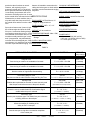
FIGURE 4
U2
U9
Simplified
layout
of the
G-9420
TP1
TP3
U5
BILLING DELAY OPTION
With the TLS and a handset connected, dial a port of the G-9420. With
the billing delay enabled, a two-second delay should be observed between
when the G-9420 goes off-hook and
when ringback tones occur in the TLS
handset. Reprogram the G-9420 to disable the billing delay (*400#), and observe no delay. Reprogram back to the
default of enabled billing delay
(*401#).
RINGBACKS
With the TLS and a handset connected, connect a phone to port 1.
With the TLS phone, call the G-9420
and count the number of rings before
the unit hangs up. This number
should match the default. Reprogram
the number of rings to 50 (*52150#)
and call the G-9420 and verify the
number of rings. Reset to the default
(*52116#).
PORT 1 CUT-THROUGH
With the TLS and a handset connected, connect another phone to port
1. Power off the G-9420 and see that a
call will go through to port 1.
Phone Drive Tes
Attach 5 bell equivalent phones to a
port and ring that port. All phones
should ring!
FCC TESTS
Apply 1500 Vrms, 60 Hz from T to R of
the line in. This should not damage
the G-9420. Apply 1500 Vrms, 60 Hz
from T and R to the chassis, with no
U3
R46
TP2
U4
U8
J3
TP7
R11
LE1
through
LE12
R10
damage to the G-9420. Apply 100
Vrms, 60 Hz to T&R and T&R to chassis of all ports. No damage and no potential present at the line in port or another port should result.
tinguish except the port to be called and
the priority port if programmed. The processor alternately places loop current and
ring voltage on the port using K4. The
red LED, LE3, will flash alternately with
the port LED (yellow) of the port ringing.
Measure the line out noise level with
If the device on the port goes off-hook
all phones on-hook. This should be
during ringing, the ringing voltage colless than -60 dBm.
lapse detector, U9, will command the
ringing to cease immediately. If the deMeasure the ring generator frequency.
vice goes off-hook during non-ringing,
Measure the ring generator frequency
the TS117 will detect loop current flow
while ringing a port with one phone
and the yellow port LED will go solid.
on it.
Once the port is determined by either case,
the processor connects the port to the line
by using K1 and then releases K3 to allow the port device to hold the line offTHEORY OF OPERATION
hook. If multiple connections from one
call are enabled, when the port device
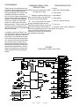
An incoming call to the G-9420 PALS
detects ringing voltage, U2, and signals goes on-hook, the line is again placed offhook by the PALS before the line is lost to
the main processor, U8. The PALS anno loop current being drawn. A doubleswers immediately by going off-hook.
beep is again sent to allow the caller to
Relay K3 is energized, the front panel
start the process over again, otherwise
LED, LE2, glows yellow and a 600 ohm
load is placed across the LINE IN to draw the PALS hangs up the line.
loop current. The call-progress tone generator, U3, is controlled to send a double- If a port device wishes to call out, it must
beep and indicate to the caller that a win- go off-hook and draw loop current from
dow of steering opportunity is available. the local voltage source placed on all the
If a DTMF tone is sent, the DTMF decoder,ports by K4 and K1. Since the port device
has drawn loop current, the PALS lights
U5, instructs the processor of the tone
its LED and the priority port LED if pronumber sent and then closes the solidstate switch, TS117, that corresponds to grammed. Also, the PALS connects the
that port and a second double-beep is ini- port device to the LINE IN using K1 such
tiated. At this point all the port LEDs ex- that the central office goes off-hook. The
G-9420
PAGE 4
January 2001
port device then functions as normal.
detector is intended to sense when the
However, with a priority port procalling device has gone on-hook and the
grammed, typically port 1, if the priority processor can then terminate the ringing
device goes off-hook while another port sequence.
is conversing, the processor will cut off
that device and hang up the line. As soon
SPECIFICATIONS
as the central office connected to the LINE
IN detects the on-hook condition, the priENCLOSURE: 19" Rack Mount, 1U
ority device will draw loop current from
the central office and then receive a dial- High, 10" Deep, aluminum
tone.
PANEL MOUNT: 8.85" x 11", 1/4"
holes
Some other features are if power is lost,
K2 will de-energize and short the LINE
WEIGHT: 4.5 lbs. maximum
IN to port 1 connection allowing at least
one outgoing connection to occur. A FAX TEMPERATURE RANGE: -20
° to +70°C,
tone detection circuit listens when a FAX operating; -35° to +85°C,
machine normally sends its type 3 tones
storage.
and, if programmed, may automatically
route the call to the assigned port. A dial- SUPPLY ISOLATION: 3500V.
tone detector, U4, checks the line for dialtone after a port has started ringing. This DATA RATE: 14.4kBPS
ON-HOOK LINE IMPEDANCE:
>10K ohms.
OFF-HOOK LINE IMPEDANCE:
Approx. 600 ohms.
SIGNAL LOSS, Line-to-Port: less than
0.2dB
RINGER EQUIVALENCE: 1.0B
PORT RINGER CAPABILITY:
5.0B, minimum
FCC REGISTRATION NO.:
IDFUSA-22979-KX-T
POWER INPUT:
8W, max. at 48Vdc (38V to 63V)
10W, max., at 125Vdc (100V to 200V)
or 115Vac (85V to 135V)
TABLE 2
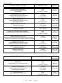
OPTIONS FOR EACH PORT
COMMAND STRING
DEFAULT
(factory settings)
Ring On Time
Sets the ring on cadence in hundredths of seconds.
*50PXXX#
P = 1-8, XXX = 001-999
XXX = 010
(1 second)
Ring Off Time
Sets the ring off cadence in hundredths of seconds.
*51PXXX#
P = 1-8, XXX = 001-999
XXX = 030
(3 seconds)
Number of Rings
Sets the number of rings before disconnecting.
*52PXX#
P = 1-8, XX = 01-99
XX = 16
(16 rings)
Tone During Ring On Time
Sets the tone that the caller will hear during the Ring On Time.
*53PX#
P = 1-8, X = 0-5(See Tone Description)
X=1
(Ring Tone)
Security Code
Enables the requirement for the caller to enter a security code
after the port code before access to the port is allowed.
*54PXXX#
P = 1-8, XXX = 000-999
XXX = 000
(Disabled)
(000 disables the security feature)
Confirmation Signal
Allows the user to enable/disable the Confirmation Signal
audible when the port is selected.
Connection Type
Sets the port connection type. This allows for a port to become
a Calling, Answer or Normal port.
*55PX#
P = 1-8, X = 0,1
(0 = Disabled, 1 = Enabled)
*56PX#
P = 2-8, X = 0-2
X=0
(Normal)
(0 = Normal, 1 = Answer, 2 = Calling)
Port 1 Interrupt Control
Allows the enabling or disabling of the
ability for Port 1 interrupts.
*57PX#
P = 2-8, X = 0,1
X=1
(Enabled)
(0 = Disabled, 1 = Enabled)
Continuation Port
Sets the next port to ring after a connection completion
of the current port.
G-9420
X=1
(Enabled)
PAGE 5
*58PX#
P = 1-8, X = 0, 1-8
(0 = Disabled)
January 2001
X=0
(Disabled)
Table 2 continued . . .
STEERING WINDOW OPTIONS
COMMAND STRING
Steering Window Start Indication
Enables/Disables the steering window
start indication.
*30X#
X = 0,1
DEFAULT
X=1
(Enabled)
(0 = Disabled, 1 = Enabled)
Steering Window Tone Cycles
Sets the number of tone cycles during the
window before defaulting to Port 1.
*31XX#
XX = 00-99
XX = 03
(3 cycles)
(0 = skip steering window)
Steering Window Tone
Sets the audible tone during the Tone On
time during the window.
*32X#
X = 0-5
X=1
(Ring Tone)
(See Tone Descriptions)
Steering Window Tone On Time
Sets the Tone On time.
*33XXX#
XXX = 000-999
XXX = 010
(1 second)
Steering Window Tone Off Time
Sets the Tone Off time.
*34XXX#
XXX = 000-999
XXX = 030
(3 seconds)
Multiple Connection Window Start Indication
Enables/Disables the steering window start indication.
*35X#
X = 0,1
X=1
(Enabled)
(0 = Disabled, 1 = Enabled)
Multiple Connection Tone Cycles
Sets the number of tone cycles for the multiple connection window.
("*"Enable this command first for all multiple connection commands)
*36XX#
XX = 00-99
XX = 00
(Disabled)
(0 = Disabled)
Multiple Connection Tone
Sets the audible tone during the Tone On
time during the multiple connection window.
*37X#
X = 0-5
(See Tone Descriptions)
Multiple Connection Tone On Time
Sets the Tone On time.
*38XXX#
XXX = 000-999
XXX = 100
(10 seconds)
*39XXX#
XXX = 000-999
XXX = 000
(0 seconds)
Multiple Tone Off Time
Sets the Tone Off time.
MISCELLANEOUS OPTIONS
COMMAND STRING
X=5
(Dial Tone)
DEFAULT
(factory settings)
Billing Delay
Enables/Disables the 2 second billing delay.
*40X#
X = 0,1
X=1
(Enabled)
(0 = Disabled, 1 = Enabled)
Answer Termination Delay
Sets the PABX on-hook delay when an
answered call is terminated.
*41XXX#
XXX = 000-999
Dial Tone Detection
Enables/Disables Dial Tone detection.
*42X#
X = 0,1
0-99.9 Seconds
(0 = Disabled, 1 = Enabled)
G-9420
XXX = 050
(5 seconds)
PAGE 6
January 2001
X=1
(Enabled)
PROGRAMMING
COMMAND STRING CODE
DESCRIPTIONS
TONE DESCRIPTIONS
0 = None
Table 2 lists all of the features that may
be altered using the programming strings
(DTMF Tones are initiated by the LINE 1 = Ring Tone (440 and 480Hz)
shown. The factory defaults are also
IN telephone key pad)
shown and typically work for 99% of the
2 = Low (350Hz)
installations used by our customers.
" * " Enables or starts the ability to pro- 3 = Mid (480Hz)
Also, if errors are made in programming,
gram a command string into processor
sometimes the G-9420 will respond er4 = High (620Hz)
at the time of the steering window.
ratically. To reload the factory defaults,
5 = Dial Tone (350 and 440 Hz)
remove the G-9420 cover and install
" # " The "#" sign (DTMF Tone Code)
jumper J3, located next to the square
P = Port (1-8)
shaped processor. Turn the power switchduring the steering window will comoff and then back on (cycle the power), mand the G-9420 to hang up or go back
ON HOOK. Exception to this is after en- X = Seconds, Tones, Cycles, Enabled or
and remove the jumper. The defaults have
tering a command string the first "#" tone default, # of rings, etc.
now been reloaded.
"sets" command into the processor and if
To program a string from Table 2, con- followed by a second "#" tone, will place
nect the G-9420 to either a telephone linethe G-9420 back ON HOOK.
or a telephone line simulator. Call the unit
and when the first double-beep is heard,
key in the command string ensuring that
the * is the first character entered. When
the command string is entered, the G9420 will respond with a double-beep to
indicate that it recognizes the string and
has stored the new parameter. The programmer may load one or multiple command strings during the same steering
window.
FIGURE 5
Simplified block diagram of the G-9420
G-9420
PAGE 7
January 2001
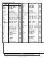
REPLACEABLE PARTS LIST, G-9420
CIRCUIT
SYMBOL
STOCK
#
DESCRIPTION
LE1,3
LED, Red, 550-0406
LE4
LED, Green, 550-0206
LE2,5-12
LED, Yellow, 550-0306
CR21-24
Diode, IN4004
CR27
Diode, 1N4148
CR25,26
Diode, IN5234B
CR53-56
Diode, IN5406
CR29-47
Diode, P6KE200CA
C13
Capacitor, EL., 330uf, 16V
C68,69
Capacitor, EL., 470uf, 50V
C12
Capacitor, EL., 220uf, 250V
C4,8,37,46,47,67 Capacitor, TAN., 1uf, 35V TAP
C39,42,45
Capacitor, TAN., 10uf, 16V TAP
C1
Capacitor, TAN., 3.3uf, 16V TAP
C25
Capacitor, TAN., 4.7uf, 16V TAP
C36
Capacitor, TAN., 6.8uf, 16V TAP
C10
Capacitor, TAN., .1uf, 35V, TAP
C19,22
Capacitor, CER., .001uf, 1KV
C5,7
Capacitor, CER., .05uf, 16V
C24,40,43,48,49,50 Capacitor, CER., .01uf, 100V
C27,28
Capacitor, CER., .003uf, 3KV
C26,38,41,44,54,69,Capacitor, CER., .1uf, 50V
70
C51,52
Capacitor, CER AX, 22pf, 100V
C31
Capacitor, MYLAR, 1uf, 200V
C2,23,53
Capacitor, MYLAR, .47uf, 250V
C3,11
Capacitor, FILM, .1uf, 250V
C15
Capacitor, POLY., 3900pf
C14
Capacitor, POLY., 4700pf
C17
Capacitor, WESCO, .00825
C16
Capacitor, WESCO, .011
C20
Capacitor, WESCO, .0187
C18,21
Capacitor, WESCO, .00487
U1,7
I.C., MC14049UBCP
U2
I.C., 4N35
U27
I.C., MC1455P1 NE555N
U9
I.C., H11AA1
U8
I.C., MC68HC705C8CFN
U13,14
I.C., TL082IP
U12
I.C., TL084IN
U5
I.C., CM8870PI
U25
I.C., TL051IP
U3
I.C., M-991
U4
I.C., M-980
U15,22
I.C., TS117
U10
Cambridge, NU-8MR-5V
010001
010002
010004
010020
010040
010110
010281
010339
020110
020111
020130
030150
030152
030153
030160
030161
030162
040000
040010
040030
040060
040080
040092
050050
050210
050270
060470
060480
070090
070150
070260
071150
080130
080320
080550
080600
080882
080940
081170
081250
081309
081330
081331
081352
081482
VR3
Voltage Reg., 115D5FS
U26
I.C., XR567ACP
U24
I.C., AT25040-10PC
Q1-3,7,8
Transistor, 2N3903
Q6
Transistor, 2N3905
Q4
Transistor, IRFZ20
K1,2
Relay, DS2E-MDC5
K3,4
Relay, DS1E-M-DC5V
R10
POT, 43P103
R11
POT, 43P502
R46
POT, 67YR10K
R4,7,16,35-42,64, Resistor, COMP., 1/4W, 1K
67
R45,60,61,65,68,69,Resistor, COMP., 1/4W, 10K
73,74,75
R12,13,15,66
Resistor, COMP., 1/4W, 100K
R6,72
Resistor, COMP., 1/4W, 22K
R14
Resistor, COMP., 1/4W, 4.7K
R9
Resistor, COMP., 1/4W, 10M
R17-34
Resistor, COMP., 10 ohm 1/2W
RN4
RESNET, 8-1-103
RN1
RESNET, 8-1-102
RN3
RESNET, 6-1-103
RN5
RESNET, 8-2-102 (ISO)
RN2
RESNET, 6-1-102
R43
Resistor, PREC., 301.0 3010F
R3
Resistor, PREC., 590.0 5900F
R71
Resistor, PREC., 5.11K 5111F
R5,48,52,56,58
Resistor, PREC., 51.1K 5112F
R51
Resistor, PREC., 53.6K 5362F
R59
Resistor, PREC., 301.0K 3013F
R57
Resistor, PREC., 511.0K 5113F
T1
Transformer, TTPC-13
L3
Inductor, PE-52647
L4-7
Inductor, Miller 77F100K
L1,2
Inductor, PE-62892
L8
Inductor, PE-52651
PJ1,PJ2
Jack, TM2REA-2416
PJ3
Jack, TM5RE1-64
TB1
PHNX: 1776566
TB1
PHNX: 1778043
S1
Switch, 8280K115
F1
Fuseholder, 102074
F1
Fuse, 3AG, 3A
Y2
Crystal, 4.0MHz
MO5-MO11
MOV, V150LA10A
MO1,2,4
MOV, V250LA20A
R1
CL-80
Y1
Crystal, 3.5795 CTX049ND
081528
081534
081574
090050
090060
090270
100205
100206
110020
110060
110300
130030
130040
130050
130150
130260
130390
130731
139880
139967
139970
139972
139979
140720
140860
141310
141790
141800
142160
142270
150390
150460
150461
150464
150467
171098
171100
171220
171221
180000
190110
190130
250019
250142
250143
250146
250740
D A -T EL RESEARCH COMPANY , I NC .
Tomorrow's Telemetry Today
For more information about Da-Tel Research Company and our products, contact:
DA-TEL RESEARCH COMPANY, INC.
P.O. Box 1206, Montrose, CO 81402
Phone: (970) 249-6129
Toll-Free: 800-324-8388
Fax: (970) 249-8919
e-mail: [email protected] or visit us at: www.da-telresearch.com
*Equipment and/or components purchased through Da-Tel but manufactured by other companies are covered under the warranties of those manufacturers.
NOTICE
As of the date of this printing, the specifications for the G-9420 in this Instruction Information sheet apply to all G-9420 Programmable Audio Line Switch, except
as indicated. Because all Da-Tel products are continually being refined and improved, these specifications are subject to change without notice.
G-9420
PAGE 8
January 2001