1
Matrix E1 Series
(1G58x-09 and 1H582-xx)
Configuration Guide
Firmware Version 3.07.xx
P/N 9033755-22
NOTICE
Enterasys Networks reserves the right to make changes in specifications and other information contained in this
document and its web site without prior notice. The reader should in all cases consult Enterasys Networks to determine
whether any such changes have been made.
The hardware, firmware, or software described in this document is subject to change without notice.
IN NO EVENT SHALL ENTERASYS NETWORKS BE LIABLE FOR ANY INCIDENTAL, INDIRECT, SPECIAL,
OR CONSEQUENTIAL DAMAGES WHATSOEVER (INCLUDING BUT NOT LIMITED TO LOST PROFITS)
ARISING OUT OF OR RELATED TO THIS DOCUMENT, WEB SITE, OR THE INFORMATION CONTAINED IN
THEM, EVEN IF ENTERASYS NETWORKS HAS BEEN ADVISED OF, KNEW OF, OR SHOULD HAVE
KNOWN OF, THE POSSIBILITY OF SUCH DAMAGES.
Enterasys Networks, Inc.
50 Minuteman Road
Andover, MA 01810
© 2008 Enterasys Networks, Inc. All rights reserved.
Part Number: 9033755-22 September 2008
ENTERASYS, ENTERASYS NETWORKS, ENTERASYS MATRIX, ENTERASYS NETSIGHT, LANVIEW,
WEBVIEW, and any logos associated therewith, are trademarks or registered trademarks of Enterasys Networks, Inc., in
the United States and other countries.
All other product names mentioned in this manual may be trademarks or registered trademarks of their respective
companies.
Documentation URL: http://www.enterasys.com/support/manuals
Documentacion URL: http://www.enterasys.com/support/manuals
Dokumentation im Internet: http://www.enterasys.com/support/manuals
Version:
Information in this guide refers to Matrix E1 Series (1G58x-09 and
1H582-xx) firmware version 3.07.xx.
ENTERASYS NETWORKS, INC. FIRMWARE LICENSE AGREEMENT
BEFORE OPENING OR UTILIZING THE ENCLOSED PRODUCT,
CAREFULLY READ THIS LICENSE AGREEMENT.
This document is an agreement (“Agreement”) between the end user (“You”) and Enterasys Networks, Inc., on behalf of
itself and its Affiliates (as hereinafter defined) (“Enterasys”) that sets forth Your rights and obligations with respect to
the Enterasys software program/firmware (including any accompanying documentation, hardware or media)
(“Program”) in the package and prevails over any additional, conflicting or inconsistent terms and conditions appearing
on any purchase order or other document submitted by You. “Affiliate” means any person, partnership, corporation,
limited liability company, other form of enterprise that directly or indirectly through one or more intermediaries,
controls, or is controlled by, or is under common control with the party specified. This Agreement constitutes the entire
understanding between the parties, with respect to the subject matter of this Agreement. The Program may be contained
in firmware, chips or other media.
BY INSTALLING OR OTHERWISE USING THE PROGRAM, YOU REPRESENT THAT YOU ARE
AUTHORIZED TO ACCEPT THESE TERMS ON BEHALF OF THE END USER (IF THE END USER IS AN
ENTITY ON WHOSE BEHALF YOU ARE AUTHORIZED TO ACT, “YOU” AND “YOUR” SHALL BE DEEMED
TO REFER TO SUCH ENTITY) AND THAT YOU AGREE THAT YOU ARE BOUND BY THE TERMS OF THIS
AGREEMENT, WHICH INCLUDES, AMONG OTHER PROVISIONS, THE LICENSE, THE DISCLAIMER OF
WARRANTY AND THE LIMITATION OF LIABILITY. IF YOU DO NOT AGREE TO THE TERMS OF THIS
AGREEMENT OR ARE NOT AUTHORIZED TO ENTER INTO THIS AGREEMENT, ENTERASYS IS
UNWILLING TO LICENSE THE PROGRAM TO YOU AND YOU AGREE TO RETURN THE UNOPENED
PRODUCT TO ENTERASYS OR YOUR DEALER, IF ANY, WITHIN TEN (10) DAYS FOLLOWING THE DATE
OF RECEIPT FOR A FULL REFUND.
IF YOU HAVE ANY QUESTIONS ABOUT THIS AGREEMENT, CONTACT ENTERASYS NETWORKS, LEGAL
DEPARTMENT AT (978) 684-1000.
You and Enterasys agree as follows:
1. LICENSE. You have the non-exclusive and non-transferable right to use only the one (1) copy of the Program
provided in this package subject to the terms and conditions of this Agreement.
2. RESTRICTIONS. Except as otherwise authorized in writing by Enterasys, You may not, nor may You permit any
third party to:
(a) Reverse engineer, decompile, disassemble or modify the Program, in whole or in part, including for reasons of
error correction or interoperability, except to the extent expressly permitted by applicable law and to the extent
the parties shall not be permitted by that applicable law, such rights are expressly excluded. Information
necessary to achieve interoperability or correct errors is available from Enterasys upon request and upon
payment of Enterasys’ applicable fee.
(b) Incorporate the Program in whole or in part, in any other product or create derivative works based on the
Program, in whole or in part.
(c) Publish, disclose, copy reproduce or transmit the Program, in whole or in part.
(d) Assign, sell, license, sublicense, rent, lease, encumber by way of security interest, pledge or otherwise transfer
the Program, in whole or in part.
(e) Remove any copyright, trademark, proprietary rights, disclaimer or warning notice included on or embedded in
any part of the Program.
3. APPLICABLE LAW. This Agreement shall be interpreted and governed under the laws and in the state and federal
courts of the Commonwealth of Massachusetts without regard to its conflicts of laws provisions. You accept the personal
jurisdiction and venue of the Commonwealth of Massachusetts courts. None of the 1980 United Nations Convention on
the Limitation Period in the International Sale of Goods, and the Uniform Computer Information Transactions Act shall
apply to this Agreement.
4. EXPORT RESTRICTIONS. You understand that Enterasys and its Affiliates are subject to regulation by agencies
of the U.S. Government, including the U.S. Department of Commerce, which prohibit export or diversion of certain
technical products to certain countries, unless a license to export the product is obtained from the U.S. Government or an
exception from obtaining such license may be relied upon by the exporting party.
If the Program is exported from the United States pursuant to the License Exception CIV under the U.S. Export
Administration Regulations, You agree that You are a civil end user of the Program and agree that You will use the
Program for civil end uses only and not for military purposes.
If the Program is exported from the United States pursuant to the License Exception TSR under the U.S. Export
Administration Regulations, in addition to the restriction on transfer set forth in Section 1 or 2 of this Agreement, You
agree not to (i) reexport or release the Program, the source code for the Program or technology to a national of a country
in Country Groups D:1 or E:2 (Albania, Armenia, Azerbaijan, Belarus, Cambodia, Cuba, Georgia, Iraq, Kazakhstan,
Laos, Libya, Macau, Moldova, Mongolia, North Korea, the People’s Republic of China, Russia, Tajikistan,
Turkmenistan, Ukraine, Uzbekistan, Vietnam, or such other countries as may be designated by the United States
Government), (ii) export to Country Groups D:1 or E:2 (as defined herein) the direct product of the Program or the
technology, if such foreign produced direct product is subject to national security controls as identified on the U.S.
Commerce Control List, or (iii) if the direct product of the technology is a complete plant or any major component of a
plant, export to Country Groups D:1 or E:2 the direct product of the plant or a major component thereof, if such foreign
produced direct product is subject to national security controls as identified on the U.S. Commerce Control List or is
subject to State Department controls under the U.S. Munitions List.
5. UNITED STATES GOVERNMENT RESTRICTED RIGHTS. The enclosed Program (i) was developed solely
at private expense; (ii) contains “restricted computer software” submitted with restricted rights in accordance with section
52.227-19 (a) through (d) of the Commercial Computer Software-Restricted Rights Clause and its successors, and (iii) in
all respects is proprietary data belonging to Enterasys and/or its suppliers. For Department of Defense units, the Program
is considered commercial computer software in accordance with DFARS section 227.7202-3 and its successors, and use,
duplication, or disclosure by the U.S. Government is subject to restrictions set forth herein.
6. DISCLAIMER OF WARRANTY. EXCEPT FOR THOSE WARRANTIES EXPRESSLY PROVIDED TO YOU
IN WRITING BY ENTERASYS, ENTERASYS DISCLAIMS ALL WARRANTIES, EITHER EXPRESS OR
IMPLIED, INCLUDING BUT NOT LIMITED TO IMPLIED WARRANTIES OF MERCHANTABILITY,
SATISFACTORY QUALITY, FITNESS FOR A PARTICULAR PURPOSE, TITLE AND NON-INFRINGEMENT
WITH RESPECT TO THE PROGRAM. IF IMPLIED WARRANTIES MAY NOT BE DISCLAIMED BY
APPLICABLE LAW, THEN ANY IMPLIED WARRANTIES ARE LIMITED IN DURATION TO THIRTY (30)
DAYS AFTER DELIVERY OF THE PROGRAM TO YOU.
7. LIMITATION OF LIABILITY. IN NO EVENT SHALL ENTERASYS OR ITS SUPPLIERS BE LIABLE FOR
ANY DAMAGES WHATSOEVER (INCLUDING, WITHOUT LIMITATION, DAMAGES FOR LOSS OF
BUSINESS, PROFITS, BUSINESS INTERRUPTION, LOSS OF BUSINESS INFORMATION, SPECIAL,
INCIDENTAL, CONSEQUENTIAL, OR RELIANCE DAMAGES, OR OTHER LOSS) ARISING OUT OF THE USE
OR INABILITY TO USE THE PROGRAM, EVEN IF ENTERASYS HAS BEEN ADVISED OF THE POSSIBILITY
OF SUCH DAMAGES. THIS FOREGOING LIMITATION SHALL APPLY REGARDLESS OF THE CAUSE OF
ACTION UNDER WHICH DAMAGES ARE SOUGHT.
THE CUMULATIVE LIABILITY OF ENTERASYS TO YOU FOR ALL CLAIMS RELATING TO THE
PROGRAM, IN CONTRACT, TORT OR OTHERWISE, SHALL NOT EXCEED THE TOTAL AMOUNT OF FEES
PAID TO ENTERASYS BY YOU FOR THE RIGHTS GRANTED HEREIN.
8. AUDIT RIGHTS. You hereby acknowledge that the intellectual property rights associated with the Program are of
critical value to Enterasys, and, accordingly, You hereby agree to maintain complete books, records and accounts showing
(i) license fees due and paid, and (ii) the use, copying and deployment of the Program. You also grant to Enterasys and
its authorized representatives, upon reasonable notice, the right to audit and examine during Your normal business hours,
Your books, records, accounts and hardware devices upon which the Program may be deployed to verify compliance with
this Agreement, including the verification of the license fees due and paid Enterasys and the use, copying and deployment
of the Program. Enterasys’ right of examination shall be exercised reasonably, in good faith and in a manner calculated
to not unreasonably interfere with Your business. In the event such audit discovers non-compliance with this Agreement,
including copies of the Program made, used or deployed in breach of this Agreement, You shall promptly pay to Enterasys
the appropriate license fees. Enterasys reserves the right, to be exercised in its sole discretion and without prior notice, to
terminate this license, effective immediately, for failure to comply with this Agreement. Upon any such termination, You
shall immediately cease all use of the Program and shall return to Enterasys the Program and all copies of the Program.
9. OWNERSHIP. This is a license agreement and not an agreement for sale. You acknowledge and agree that the
Program constitutes trade secrets and/or copyrighted material of Enterasys and/or its suppliers. You agree to implement
reasonable security measures to protect such trade secrets and copyrighted material. All right, title and interest in and to
the Program shall remain with Enterasys and/or its suppliers. All rights not specifically granted to You shall be reserved
to Enterasys.
10. ENFORCEMENT. You acknowledge and agree that any breach of Sections 2, 4, or 9 of this Agreement by You
may cause Enterasys irreparable damage for which recovery of money damages would be inadequate, and that Enterasys
may be entitled to seek timely injunctive relief to protect Enterasys’ rights under this Agreement in addition to any and
all remedies available at law.
11. ASSIGNMENT. You may not assign, transfer or sublicense this Agreement or any of Your rights or obligations
under this Agreement, except that You may assign this Agreement to any person or entity which acquires substantially all
of Your stock assets. Enterasys may assign this Agreement in its sole discretion. This Agreement shall be binding upon
and inure to the benefit of the parties, their legal representatives, permitted transferees, successors and assigns as
permitted by this Agreement. Any attempted assignment, transfer or sublicense in violation of the terms of this Agreement
shall be void and a breach of this Agreement.
12. WAIVER. A waiver by Enterasys of a breach of any of the terms and conditions of this Agreement must be in
writing and will not be construed as a waiver of any subsequent breach of such term or condition. Enterasys’ failure to
enforce a term upon Your breach of such term shall not be construed as a waiver of Your breach or prevent enforcement
on any other occasion.
13. SEVERABILITY. In the event any provision of this Agreement is found to be invalid, illegal or unenforceable, the
validity, legality and enforceability of any of the remaining provisions shall not in any way be affected or impaired
thereby, and that provision shall be reformed, construed and enforced to the maximum extent permissible. Any such
invalidity, illegality, or unenforceability in any jurisdiction shall not invalidate or render illegal or unenforceable such
provision in any other jurisdiction.
14. TERMINATION. Enterasys may terminate this Agreement immediately upon Your breach of any of the terms and
conditions of this Agreement. Upon any such termination, You shall immediately cease all use of the Program and shall
return to Enterasys the Program and all copies of the Program.
Contents
Figures .........................................................................................................................................xxv
Tables......................................................................................................................................... xxvii
ABOUT THIS GUIDE
Using This Guide......................................................................................................... xxix
Structure of This Guide ................................................................................................xxx
Related Documents..................................................................................................... xxxi
Document Conventions.............................................................................................. xxxii
Typographical and Keystroke Conventions................................................................ xxxii
1
INTRODUCTION
1.1
1.2
2
MANAGEMENT TERMINAL AND MODEM SETUP REQUIREMENTS
2.1
3
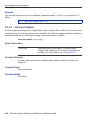
Overview ......................................................................................................... 1-1
Getting Help .................................................................................................... 1-3
Connecting to a Console Port for Local Management .................................... 2-1
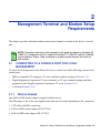
2.1.1
What Is Needed .............................................................................. 2-1
2.1.2
Connecting to an IBM or Compatible Device .................................. 2-2
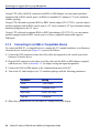
2.1.3
Connecting to a VT Series Terminal ............................................... 2-3
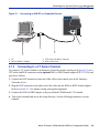
2.1.4
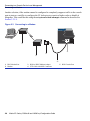
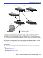
Connecting to a Modem.................................................................. 2-4
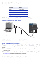
2.1.4.1
Configuring the Modem to Not Send Login Requests . 2-5
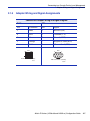
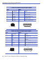
2.1.5
Adapter Wiring and Signal Assignments......................................... 2-7
STARTUP AND GENERAL CONFIGURATION
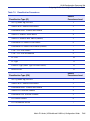
3.1
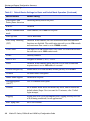
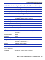
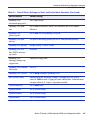
Startup and General Configuration Summary ................................................. 3-1
3.1.1
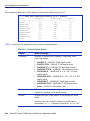
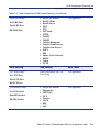
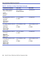
Factory Default Settings.................................................................. 3-1
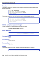
3.1.2
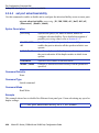
Command Defaults Descriptions .................................................. 3-10
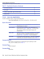
3.1.3
CLI Command Modes ................................................................... 3-11
3.1.4
Using WebView............................................................................. 3-12
3.1.5
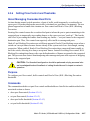
Process Overview: CLI Startup and General Configuration.......... 3-13
3.1.6
Starting and Navigating the Command Line Interface (CLI) ......... 3-14
3.1.6.1
Using a Console Port Connection ............................. 3-14
3.1.6.2
Logging in with a Default User Account..................... 3-14
Matrix E1 Series (1G58x-09 and 1H582-xx) Configuration Guide
v
Contents
3.1.6.3
3.2
vi
Logging in With an Administratively Configured
User Account ............................................................. 3-16
3.1.6.4
Using a Telnet Connection ........................................ 3-16
3.1.7
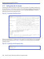
Getting Help with CLI Syntax ........................................................ 3-18
3.1.8
Displaying Scrolling Screens ........................................................ 3-19
3.1.9
Basic Line Editing Commands ...................................................... 3-20
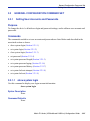
General Configuration Command Set ........................................................... 3-21
3.2.1
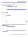
Setting User Accounts and Passwords......................................... 3-21
3.2.1.1
show system login ..................................................... 3-21
3.2.1.2
set system login......................................................... 3-23
3.2.1.3
clear system login...................................................... 3-24
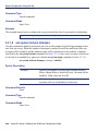
3.2.1.4
set password ............................................................. 3-25
3.2.1.5
set system password length ...................................... 3-26
3.2.1.6
set system password aging ....................................... 3-27
3.2.1.7
set system password history ..................................... 3-27
3.2.1.8
set system lockout attempts ...................................... 3-28
3.2.1.9
set system lockout ..................................................... 3-29
3.2.2
Setting Basic Device Properties.................................................... 3-30
3.2.2.1
show system resources ............................................. 3-31
3.2.2.2
show system.............................................................. 3-32
3.2.2.3
show time .................................................................. 3-33
3.2.2.4
set time ...................................................................... 3-33
3.2.2.5
set prompt.................................................................. 3-34
3.2.2.6
show banner motd ..................................................... 3-35
3.2.2.7
set banner motd......................................................... 3-35
3.2.2.8
clear banner motd...................................................... 3-36
3.2.2.9
show version.............................................................. 3-37
3.2.2.10
set system name ....................................................... 3-38
3.2.2.11
set system location .................................................... 3-39
3.2.2.12
set system contact..................................................... 3-40
3.2.2.13
show terminal ............................................................ 3-40
3.2.2.14
set terminal ................................................................ 3-41
3.2.2.15
set system timeout..................................................... 3-42
3.2.2.16
show summertime ..................................................... 3-42
3.2.2.17
set summertime ......................................................... 3-43
3.2.2.18
set summertime date ................................................. 3-44
3.2.2.19
set summertime recurring.......................................... 3-45
3.2.2.20
clear summertime ...................................................... 3-47
3.2.2.21
set console baud ....................................................... 3-47
3.2.2.22
show ip address......................................................... 3-48
3.2.2.23
set ip address ............................................................ 3-49
Matrix E1 Series (1G58x-09 and 1H582-xx) Configuration Guide
Contents
3.2.3
3.3
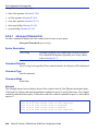
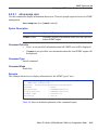
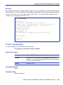
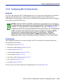
Downloading a Firmware Image ................................................... 3-50
3.2.3.1
Downloading via the Serial Port ................................ 3-50
3.2.3.2
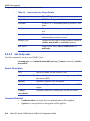
Downloading via TFTP .............................................. 3-51
3.2.4
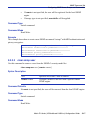
Configuring Telnet......................................................................... 3-54
3.2.4.1
show telnet ................................................................ 3-54
3.2.4.2
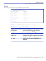
set telnet .................................................................... 3-55
3.2.5
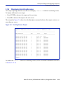
Managing Switch Configuration Files............................................ 3-57
3.2.5.1
dir............................................................................... 3-57
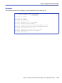
3.2.5.2
show config................................................................ 3-58
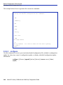
3.2.5.3
configure.................................................................... 3-60
3.2.5.4
summaryconfig .......................................................... 3-62
3.2.5.5
copy ........................................................................... 3-64
3.2.5.6
set system bootconfig................................................ 3-66
3.2.5.7
delete......................................................................... 3-67
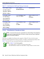
3.2.6
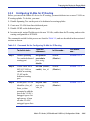
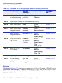
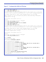
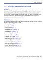
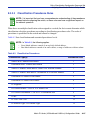
Configuring Enterasys and Cisco Discovery Protocols................. 3-68
3.2.6.1
show cdp ................................................................... 3-69
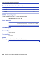
3.2.6.2
set cdp ....................................................................... 3-70
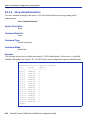
3.2.6.3
set cdp interval .......................................................... 3-72
3.2.6.4
show ciscodp ............................................................. 3-72
3.2.6.5
set ciscodp status ...................................................... 3-74
3.2.6.6
set ciscodp timer........................................................ 3-74
3.2.6.7
set ciscodp holdtime .................................................. 3-75
3.2.6.8
set ciscodp populatecdp ............................................ 3-76
3.2.6.9
show port ciscodp info ............................................... 3-76
3.2.6.10
show port ciscodp neighborinfo ................................. 3-78
3.2.6.11
set port ciscodp status............................................... 3-79
3.2.6.12
set port ciscodp trust-ext ........................................... 3-80
3.2.6.13
set port ciscodp cos-ext............................................. 3-81
3.2.6.14
set port ciscodp vvid .................................................. 3-82
3.2.7
Pausing, Clearing and Closing the CLI ......................................... 3-84
3.2.7.1
wait ............................................................................ 3-84
3.2.7.2
cls (clear screen) ....................................................... 3-85
3.2.7.3
exit ............................................................................. 3-85
3.2.8
Resetting the Device..................................................................... 3-87
3.2.8.1
show reset ................................................................. 3-87
3.2.8.2
reset........................................................................... 3-88
3.2.8.3
reset at....................................................................... 3-89
3.2.8.4
reset in....................................................................... 3-90
3.2.8.5
clear config ................................................................ 3-90
Preparing the Device for Router Mode.......................................................... 3-92
3.3.1
Pre-Routing Configuration Tasks.................................................. 3-92
3.3.2
Configuring VLANs for IP Routing ................................................ 3-93
3.3.3
Enabling Router Configuration Modes .......................................... 3-96
Matrix E1 Series (1G58x-09 and 1H582-xx) Configuration Guide
vii
Contents
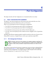
4
PORT CONFIGURATION
4.1
4.2
4.3
viii
Port Configuration Summary........................................................................... 4-1
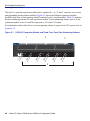
4.1.1
Port Assignment Scheme ............................................................... 4-1
4.1.2
Port String Syntax Used in the CLI ................................................. 4-4
Process Overview: Port Configuration ............................................................ 4-6
Port Configuration Command Set ................................................................... 4-7
4.3.1
Reviewing Port Status..................................................................... 4-7
4.3.1.1
show port status .......................................................... 4-7
4.3.1.2
show port counters ...................................................... 4-9
4.3.1.3
clear port counters..................................................... 4-11
4.3.2
Disabling / Enabling Ports............................................................. 4-12
4.3.2.1
set port disable .......................................................... 4-12
4.3.2.2
set port enable........................................................... 4-13
4.3.3
Setting Speed and Duplex Mode .................................................. 4-13
4.3.3.1
show port speed ........................................................ 4-14
4.3.3.2
set port speed............................................................ 4-15
4.3.3.3
show port duplex ....................................................... 4-16
4.3.3.4
set port duplex ........................................................... 4-17
4.3.4
Enabling / Disabling Jumbo Frame Support ................................. 4-18
4.3.4.1
show port jumbo ........................................................ 4-18
4.3.4.2
set port jumbo............................................................ 4-19
4.3.5
Setting Port Auto-Negotiation and Advertised Ability.................... 4-20
4.3.5.1
show port negotiation ................................................ 4-21
4.3.5.2
set port negotiation .................................................... 4-22
4.3.5.3
show port advertised ability ....................................... 4-23
4.3.5.4
set port advertised ability........................................... 4-26
4.3.6
Setting Flow Control and Thesholds ............................................. 4-27
4.3.6.1
show port flowcontrol................................................. 4-28
4.3.6.2
set port flowcontrol .................................................... 4-29
4.3.6.3
show port buffer threshold ......................................... 4-30
4.3.6.4
set port buffer threshold............................................. 4-31
4.3.6.5
show flow agetime ..................................................... 4-34
4.3.6.6
set flow agetime......................................................... 4-35
4.3.6.7
clear flow agetime...................................................... 4-35
4.3.6.8
show port holbp ......................................................... 4-36
4.3.6.9
set port holbp............................................................. 4-37
4.3.7
Setting Port Traps ......................................................................... 4-39
4.3.7.1
show port trap............................................................ 4-39
4.3.7.2
set port trap ............................................................... 4-41
4.3.8
Overview: Port Mirroring ............................................................... 4-42
Matrix E1 Series (1G58x-09 and 1H582-xx) Configuration Guide
Contents
4.3.9
4.3.10
4.3.11
4.3.12
4.3.13
4.3.14
4.3.15
5
Setting Port Mirroring .................................................................... 4-43
4.3.9.1
show port mirroring.................................................... 4-43
4.3.9.2
set port mirroring ....................................................... 4-44
4.3.9.3
clear port mirroring .................................................... 4-45
Configuring Link Aggregation........................................................ 4-46
4.3.10.1
Matrix E1 Trunk and LAG Usage Considerations...... 4-46
4.3.10.2
Port Grouping Considerations ................................... 4-47
Configuring Static Port Trunking ................................................... 4-50
4.3.11.1
show trunk ................................................................. 4-51
4.3.11.2
set trunkmode............................................................ 4-54
4.3.11.3
set trunk..................................................................... 4-54
4.3.11.4
clear trunk.................................................................. 4-55
4.3.11.5
set trunk port.............................................................. 4-56
4.3.11.6
clear trunk port........................................................... 4-56
4.3.11.7
set trunk algorithm ..................................................... 4-57
Link Aggregation Control Protocol (LACP) ................................... 4-59
4.3.12.1
LACP Operation ........................................................ 4-59
4.3.12.2
LACP Terminology .................................................... 4-60
4.3.12.3
Matrix E1 LAG Usage Considerations....................... 4-61
Configuring Link Aggregation........................................................ 4-63
4.3.13.1
set lacp ...................................................................... 4-63
4.3.13.2
set lacp static............................................................. 4-64
4.3.13.3
clear lacp static.......................................................... 4-65
4.3.13.4
show port lacp ........................................................... 4-66
4.3.13.5
set port lacp ............................................................... 4-68
Configuring Port Broadcast Suppression...................................... 4-70
4.3.14.1
show port broadcast .................................................. 4-70
4.3.14.2
set port broadcast...................................................... 4-71
Configuring Unknown Destination Address Suppression ............. 4-73
4.3.15.1
show port unknowndestsuppress .............................. 4-73
4.3.15.2
set port unknowndestsuppress.................................. 4-74
4.3.15.3
clear port unknowndestsuppress............................... 4-75
SNMP CONFIGURATION
5.1
5.2
SNMP Configuration Summary ....................................................................... 5-1
5.1.1
SNMPv1 and SNMPv2.................................................................... 5-1
5.1.2
SNMPv3.......................................................................................... 5-2
5.1.3
About SNMP Security Models and Levels ...................................... 5-2
5.1.4
Process Overview: SNMP Configuration ........................................ 5-3
SNMP Command Set...................................................................................... 5-5
5.2.1
Disabling / Enabling and Reviewing SNMP Statistics..................... 5-5
5.2.1.1
show snmp .................................................................. 5-5
Matrix E1 Series (1G58x-09 and 1H582-xx) Configuration Guide
ix
Contents
5.2.2
5.2.3
5.2.4
5.2.5
5.2.6
5.2.7
x
5.2.1.2
set snmp ...................................................................... 5-6
5.2.1.3
show snmp engineid.................................................... 5-6
5.2.1.4
show snmp counters.................................................... 5-7
Configuring SNMP Users, Groups and Communities ................... 5-14
5.2.2.1
show snmp user ........................................................ 5-15
5.2.2.2
set snmp user ............................................................ 5-16
5.2.2.3
clear snmp user ......................................................... 5-17
5.2.2.4
show snmp group ...................................................... 5-18
5.2.2.5
set snmp group.......................................................... 5-20
5.2.2.6
clear snmp group....................................................... 5-21
5.2.2.7
show community........................................................ 5-22
5.2.2.8
set community ........................................................... 5-23
5.2.2.9
clear community ........................................................ 5-24
5.2.2.10
show snmp community .............................................. 5-24
5.2.2.11
set snmp community.................................................. 5-25
5.2.2.12
clear snmp community............................................... 5-26
Configuring SNMP Access Rights ................................................ 5-27
5.2.3.1
show snmp access .................................................... 5-27
5.2.3.2
set snmp access........................................................ 5-29
5.2.3.3
clear snmp access..................................................... 5-31
5.2.3.4
show snmp authenticationtrap................................... 5-31
5.2.3.5
set snmp authentication trap ..................................... 5-32
Configuring SNMP MIB Views ...................................................... 5-33
5.2.4.1
show snmp view ........................................................ 5-33
5.2.4.2
set snmp view............................................................ 5-35
5.2.4.3
clear snmp view......................................................... 5-35
Configuring SNMP Target Parameters ......................................... 5-37
5.2.5.1
show snmp targetparams .......................................... 5-37
5.2.5.2
set snmp targetparams.............................................. 5-39
5.2.5.3
clear snmp targetparams........................................... 5-41
Configuring SNMP Target Addresses........................................... 5-42
5.2.6.1
show snmp targetaddr ............................................... 5-42
5.2.6.2
set snmp targetaddr................................................... 5-44
5.2.6.3
clear snmp targetaddr................................................ 5-46
Configuring SNMP Notification Parameters.................................. 5-47
5.2.7.1
show trap ................................................................... 5-48
5.2.7.2
set trap....................................................................... 5-49
5.2.7.3
clear trap.................................................................... 5-49
5.2.7.4
show newaddrtrap ..................................................... 5-50
5.2.7.5
set newaddrtrap......................................................... 5-51
5.2.7.6
show snmp notify....................................................... 5-52
5.2.7.7
set snmp notify .......................................................... 5-54
5.2.7.8
clear snmp notify ....................................................... 5-55
Matrix E1 Series (1G58x-09 and 1H582-xx) Configuration Guide
Contents
5.2.8
6
5.2.7.9
show snmp notifyfilter ................................................ 5-56
5.2.7.10
set snmp notifyfilter.................................................... 5-57
5.2.7.11
clear snmp notifyfilter................................................. 5-58
5.2.7.12
show snmp notifyprofile ............................................. 5-59
5.2.7.13
set snmp notifyprofile................................................. 5-60
5.2.7.14
clear snmp notifyprofile.............................................. 5-60
Basic SNMP Trap Configuration ................................................... 5-62
SPANNING TREE CONFIGURATION
6.1
6.2
Spanning Tree Configuration Summary.......................................................... 6-1
6.1.1
Overview: Single, Rapid and Multiple Spanning Tree Protocols..... 6-1
6.1.2
Spanning Tree Features ................................................................. 6-2
6.1.3
Process Overview: Spanning Tree Configuration ........................... 6-3
Spanning Tree Configuration Command Set .................................................. 6-4
6.2.1
Reviewing and Setting Spanning Tree Bridge Parameters............. 6-4
6.2.1.1
show spantree stats..................................................... 6-6
6.2.1.2
set spantree................................................................. 6-9
6.2.1.3
show spantree version............................................... 6-10
6.2.1.4
set spantree version .................................................. 6-11
6.2.1.5
clear spantree version ............................................... 6-11
6.2.1.6
show spantree mstilist ............................................... 6-12
6.2.1.7
set spantree msti ....................................................... 6-13
6.2.1.8
clear spantree msti .................................................... 6-13
6.2.1.9
show spantree mstmap ............................................. 6-14
6.2.1.10
set spantree mstmap ................................................. 6-15
6.2.1.11
clear spantree mstmap .............................................. 6-16
6.2.1.12
show spantree vlanlist ............................................... 6-16
6.2.1.13
show spantree mstcfgid............................................. 6-17
6.2.1.14
set spantree mstcfgid ................................................ 6-18
6.2.1.15
clear spantree mstcfgid ............................................. 6-19
6.2.1.16
set spantree priority ................................................... 6-19
6.2.1.17
clear spantree priority ................................................ 6-20
6.2.1.18
show spantree bridgehellomode................................ 6-21
6.2.1.19
set spantree bridgehellomode ................................... 6-21
6.2.1.20
clear spantree bridgehellomode ................................ 6-22
6.2.1.21
set spantree hello ...................................................... 6-22
6.2.1.22
clear spantree hello ................................................... 6-23
6.2.1.23
set spantree maxage ................................................. 6-24
6.2.1.24
clear spantree maxage .............................................. 6-25
6.2.1.25
set spantree fwddelay................................................ 6-26
6.2.1.26
clear spantree fwddelay............................................. 6-26
6.2.1.27
show spantree autoedge ........................................... 6-27
Matrix E1 Series (1G58x-09 and 1H582-xx) Configuration Guide
xi
Contents
6.2.2
xii
6.2.1.28
set spantree autoedge............................................... 6-28
6.2.1.29
clear spantree autoedge............................................ 6-28
6.2.1.30
show spantree legacypathcost .................................. 6-29
6.2.1.31
set spantree legacypathcost...................................... 6-29
6.2.1.32
clear spantree legacypathcost................................... 6-30
6.2.1.33
show spantree tctrapsuppress................................... 6-30
6.2.1.34
set spantree tctrapsuppress ...................................... 6-31
6.2.1.35
clear spantree tctrapsuppress ................................... 6-32
6.2.1.36
show spantree txholdcount........................................ 6-32
6.2.1.37
set spantree txholdcount ........................................... 6-33
6.2.1.38
clear spantree txholdcount ........................................ 6-34
6.2.1.39
set spantree maxhops ............................................... 6-34
6.2.1.40
clear spantree maxhops ............................................ 6-35
Reviewing and Setting Spanning Tree Port Parameters .............. 6-36
6.2.2.1
show spantree portadmin .......................................... 6-37
6.2.2.2
set spantree portadmin.............................................. 6-38
6.2.2.3
clear spantree portadmin........................................... 6-39
6.2.2.4
show spantree blocked ports..................................... 6-39
6.2.2.5
show spantree portpri ................................................ 6-40
6.2.2.6
set spantree portpri.................................................... 6-41
6.2.2.7
clear spantree portpri................................................. 6-42
6.2.2.8
show spantree portcost ............................................. 6-43
6.2.2.9
set spantree portcost ................................................. 6-43
6.2.2.10
clear spantree portcost .............................................. 6-45
6.2.2.11
show spantree adminedge ........................................ 6-45
6.2.2.12
set spantree adminedge ............................................ 6-46
6.2.2.13
clear spantree adminedge ......................................... 6-47
6.2.2.14
show spantree spanguard ......................................... 6-47
6.2.2.15
set spantree spanguard............................................. 6-48
6.2.2.16
clear spantree spanguard.......................................... 6-49
6.2.2.17
show spantree spanguardtimeout ............................. 6-49
6.2.2.18
set spantree spanguardtimeout ................................. 6-50
6.2.2.19
clear spantree spanguardtimeout .............................. 6-50
6.2.2.20
show spantree spanguardlock................................... 6-51
6.2.2.21
clear spantree spanguardlock ................................... 6-52
6.2.2.22
show spantree spanguardtrapenable ........................ 6-52
6.2.2.23
set spantree spanguardtrapenable............................ 6-53
6.2.2.24
clear spantree spanguardtrapenable......................... 6-54
6.2.2.25
show spantree adminpoint......................................... 6-54
6.2.2.26
set spantree adminpoint ............................................ 6-55
6.2.2.27
clear spantree adminpoint ......................................... 6-56
Matrix E1 Series (1G58x-09 and 1H582-xx) Configuration Guide
Contents
7
802.1Q VLAN CONFIGURATION
7.1
7.2
7.3
VLAN Configuration Summary ........................................................................ 7-1
7.1.1
Port Assignment Scheme ............................................................... 7-1
7.1.2
Port String Syntax Used in the CLI ................................................. 7-1
Process Overview: 802.1Q VLAN Configuration............................................. 7-2
VLAN Configuration Command Set ................................................................ 7-3
7.3.1
Reviewing Existing VLANs.............................................................. 7-3
7.3.1.1
show vlan..................................................................... 7-3
7.3.1.2
show vlan static ........................................................... 7-6
7.3.1.3
show vlan portinfo........................................................ 7-7
7.3.2
Creating and Naming Static VLANs................................................ 7-9
7.3.2.1
set vlan ........................................................................ 7-9
7.3.2.2
set vlan name ............................................................ 7-10
7.3.2.3
clear vlan ................................................................... 7-11
7.3.2.4
clear vlan name ......................................................... 7-12
7.3.3
Assigning Port VLAN IDs (PVIDs) and Ingress Filtering............... 7-13
7.3.3.1
show port vlan ........................................................... 7-13
7.3.3.2
set port vlan ............................................................... 7-14
7.3.3.3
clear port vlan ............................................................ 7-15
7.3.3.4
show port ingress filter............................................... 7-16
7.3.3.5
set port ingress filter .................................................. 7-17
7.3.4
Configuring the VLAN Egress List ................................................ 7-18
7.3.4.1
set vlan forbidden ...................................................... 7-18
7.3.4.2
show port egress ....................................................... 7-19
7.3.4.3
set vlan egress .......................................................... 7-20
7.3.4.4
clear vlan egress ....................................................... 7-21
7.3.4.5
show vlan dynamic egress ........................................ 7-22
7.3.4.6
set vlan dynamicegress ............................................. 7-23
7.3.5
Assigning VLANs According to Classification Rules..................... 7-24
7.3.5.1
show vlan classification ............................................. 7-24
7.3.5.2
set vlan classification................................................. 7-25
7.3.5.3
Valid Values for VLAN Classification and Frame
Filtering...................................................................... 7-28
7.3.5.4
Classification Precedence Rules ............................... 7-32
7.3.5.5
clear vlan classification.............................................. 7-34
7.3.5.6
set vlan classification ingress .................................... 7-35
7.3.5.7
clear vlan classification ingress ................................. 7-36
7.3.6
Setting the Host VLAN .................................................................. 7-38
7.3.6.1
show host vlan........................................................... 7-38
7.3.6.2
set port vlan host ...................................................... 7-39
7.3.6.3
clear host vlan ........................................................... 7-40
7.3.7
Creating a Secure Management VLAN......................................... 7-41
Matrix E1 Series (1G58x-09 and 1H582-xx) Configuration Guide
xiii
Contents
7.3.8
8
POLICY CLASSIFICATION CONFIGURATION
8.1
8.2
8.3
9
Policy Classification Configuration Summary.................................................. 8-1
Process Overview: Policy Classification Configuration ................................... 8-1
Policy Classification Configuration Command Set .......................................... 8-2
8.3.1
Configuring Policy Profiles .............................................................. 8-2
8.3.1.1
show policy profile ....................................................... 8-2
8.3.1.2
set policy profile........................................................... 8-4
8.3.1.3
clear policy profile........................................................ 8-5
8.3.1.4
show policy invalid action ............................................ 8-5
8.3.1.5
set policy invalid action................................................ 8-6
8.3.1.6
clear policy invalid action............................................. 8-7
8.3.2
Assigning Classification Rules to Policy Profiles ............................ 8-8
8.3.2.1
show policy class......................................................... 8-8
8.3.2.2
set policy classify......................................................... 8-9
8.3.2.3
Classification Precedence Rules ............................... 8-15
8.3.2.4
clear policy class ....................................................... 8-16
8.3.2.5
show policy maptable ................................................ 8-17
8.3.2.6
show vlanauthorization .............................................. 8-18
8.3.2.7
set vlanauthorization.................................................. 8-19
8.3.2.8
set policy maptable response .................................... 8-20
8.3.2.9
clear policy maptable response ................................. 8-20
8.3.2.10
set policy maptable.................................................... 8-21
8.3.2.11
clear policy maptable................................................. 8-22
8.3.3
Assigning Ports to Policy Profiles ................................................. 8-23
8.3.3.1
show policy port......................................................... 8-23
8.3.3.2
set policy port ............................................................ 8-24
8.3.3.3
clear policy port ......................................................... 8-25
PORT PRIORITY AND CLASSIFICATION CONFIGURATION
9.1
9.2
xiv
Enabling/Disabling GVRP (GARP VLAN Registration Protocol)... 7-42
7.3.8.1
show gvrp .................................................................. 7-44
7.3.8.2
show garp timer ......................................................... 7-45
7.3.8.3
set gvrp...................................................................... 7-47
7.3.8.4
set garp timer............................................................. 7-48
Port Priority and Classification Configuration Summary ................................. 9-1
9.1.1
Priority............................................................................................. 9-1
9.1.2
Priority Queueing Modes (Algorithms) ............................................ 9-2
9.1.3
Port Classification ........................................................................... 9-3
Process Overview: Priority, Classification,
And Rate Limiting Configuration ..................................................................... 9-4
Matrix E1 Series (1G58x-09 and 1H582-xx) Configuration Guide
Contents
9.3
10
Port Priority and Classification Configuration Commands .............................. 9-4
9.3.1
Configuring Port Priority.................................................................. 9-4
9.3.1.1
show port priority ......................................................... 9-5
9.3.1.2
set port priority............................................................. 9-5
9.3.1.3
clear port priority.......................................................... 9-6
9.3.2
Configuring Priority to Transmit Queue Mapping............................ 9-7
9.3.2.1
show priority queue ..................................................... 9-7
9.3.2.2
set priority queue ......................................................... 9-9
9.3.3
Configuring Quality of Service (QoS)............................................ 9-11
9.3.3.1
show port qos ............................................................ 9-11
9.3.3.2
set port qos sp ........................................................... 9-12
9.3.3.3
set port qos wrr.......................................................... 9-13
9.3.3.4
set port qos hybrid ..................................................... 9-14
9.3.4
Configuring Priority Classification ................................................. 9-16
9.3.4.1
show priority classification ......................................... 9-17
9.3.4.2
set priority classification............................................. 9-18
9.3.4.3
Valid Values for Priority Classification ....................... 9-19
9.3.4.4
clear priority classification.......................................... 9-23
9.3.4.5
set priority classification tosvalue .............................. 9-24
9.3.4.6
set priority classification tosstatus ............................. 9-26
9.3.4.7
show priority classification qtagoverride .................... 9-27
9.3.4.8
set priority classification qtagoverride........................ 9-27
9.3.5
Classification Precedence Rules .................................................. 9-28
9.3.5.1
set priority classification ingress ................................ 9-31
9.3.5.2
clear priority classification ingress ............................. 9-32
9.3.6
Configuring Port Traffic Rate Limiting ........................................... 9-34
9.3.6.1
show port ratelimit ..................................................... 9-34
9.3.6.2
set port ratelimit ......................................................... 9-36
9.3.6.3
clear port ratelimit ...................................................... 9-37
IGMP CONFIGURATION
10.1
10.2
IGMP Configuration Summary ...................................................................... 10-1
10.1.1
Process Overview: IGMP Configuration ....................................... 10-1
IGMP Configuration Command Set............................................................... 10-2
10.2.1
Enabling / Disabling IGMP ............................................................ 10-2
10.2.1.1
show igmp ................................................................. 10-2
10.2.1.2
set igmp ..................................................................... 10-3
10.2.2
Setting IGMP Query Interval and Response Time........................ 10-4
10.2.2.1
show igmp query-interval........................................... 10-4
10.2.2.2
set igmp query-interval .............................................. 10-5
10.2.2.3
show igmp response-time.......................................... 10-5
10.2.2.4
set igmp response-time ............................................. 10-6
Matrix E1 Series (1G58x-09 and 1H582-xx) Configuration Guide
xv
Contents
10.2.3
10.3
11
LOGGING AND SWITCH NETWORK MANAGEMENT
11.1
11.2
xvi
Reviewing IGMP Groups .............................................................. 10-7
10.2.3.1
show igmp groups ..................................................... 10-7
10.2.4
Configuring IGMP VLAN Registration........................................... 10-9
10.2.4.1
show igmp mode ....................................................... 10-9
10.2.4.2
set igmp mode vlan ................................................. 10-10
10.2.4.3
set igmp mode ipaddress ........................................ 10-11
10.2.4.4
set igmp mode ......................................................... 10-12
About IGMP................................................................................................. 10-13
10.3.1
IGMP VLAN Registration ............................................................ 10-13
Process Overview: Logging and Network Management ............................... 11-1
Logging and Network Management Command Set ...................................... 11-2
11.2.1
Configuring System Logging......................................................... 11-2
11.2.1.1
set logging ................................................................. 11-3
11.2.1.2
show logging all ......................................................... 11-3
11.2.1.3
show logging console ................................................ 11-7
11.2.1.4
set logging console.................................................... 11-8
11.2.1.5
show logging server................................................... 11-8
11.2.1.6
set logging server .................................................... 11-10
11.2.1.7
clear logging server ................................................. 11-11
11.2.1.8
show logging default................................................ 11-11
11.2.1.9
set logging default ................................................... 11-12
11.2.1.10 clear logging default ................................................ 11-14
11.2.1.11 show logging application ......................................... 11-14
11.2.1.12 set logging application ............................................. 11-16
11.2.1.13 clear logging application .......................................... 11-20
11.2.1.14 show logging audit-trail............................................ 11-20
11.2.1.15 copy audit-trail ......................................................... 11-21
11.2.2
Monitoring Switch Network Events and Status ........................... 11-22
11.2.2.1
show eventlog.......................................................... 11-22
11.2.2.2
clear eventlog .......................................................... 11-23
11.2.2.3
history ...................................................................... 11-24
11.2.2.4
repeat ...................................................................... 11-24
11.2.2.5
show history............................................................. 11-26
11.2.2.6
set history ................................................................ 11-26
11.2.2.7
show netstat ............................................................ 11-27
11.2.2.8
show rmon stats ...................................................... 11-28
11.2.2.9
show users .............................................................. 11-31
11.2.2.10 disconnect ............................................................... 11-33
11.2.3
Managing Switch Network Addresses ........................................ 11-33
11.2.3.1
show arp .................................................................. 11-35
Matrix E1 Series (1G58x-09 and 1H582-xx) Configuration Guide
Contents
11.2.4
11.2.5
11.2.6
11.2.3.2
set arp...................................................................... 11-35
11.2.3.3
clear arp................................................................... 11-36
11.2.3.4
show rad .................................................................. 11-37
11.2.3.5
set rad...................................................................... 11-38
11.2.3.6
show mac ................................................................ 11-38
11.2.3.7
set mac .................................................................... 11-41
11.2.3.8
clear mac ................................................................. 11-42
11.2.3.9
show mac agingtime................................................ 11-43
11.2.3.10 set mac agingtime ................................................... 11-44
11.2.3.11 clear mac agingtime ................................................ 11-44
11.2.3.12 show port stopaging ................................................ 11-45
11.2.3.13 set port stopaging .................................................... 11-46
11.2.3.14 clear port stopaging ................................................. 11-47
11.2.3.15 set mac algorithm .................................................... 11-47
11.2.3.16 show dns ................................................................. 11-49
11.2.3.17 set dns domain ........................................................ 11-49
11.2.3.18 clear dns domain ..................................................... 11-50
11.2.3.19 set dns server .......................................................... 11-51
11.2.3.20 clear dns server ....................................................... 11-51
11.2.3.21 clear dns .................................................................. 11-52
11.2.3.22 ping.......................................................................... 11-53
11.2.3.23 traceroute ................................................................ 11-55
11.2.3.24 set mac multicast..................................................... 11-57
11.2.3.25 show mac multicast ................................................. 11-59
Configuring Simple Network Time Protocol (SNTP) ................... 11-60
11.2.4.1
show sntp ................................................................ 11-60
11.2.4.2
set sntp client........................................................... 11-61
11.2.4.3
set sntp broadcastdelay........................................... 11-62
11.2.4.4
set sntp poll-interval................................................. 11-62
11.2.4.5
set sntp server ......................................................... 11-63
11.2.4.6
clear sntp server ...................................................... 11-64
11.2.4.7
set timezone ............................................................ 11-65
11.2.4.8
clear timezone ......................................................... 11-65
Configuring Node Aliases ........................................................... 11-67
11.2.5.1
show nodealias........................................................ 11-67
11.2.5.2
show nodealias config ............................................. 11-69
11.2.5.3
set nodealias ........................................................... 11-70
11.2.5.4
set nodealias maxentries......................................... 11-71
11.2.5.5
clear nodealias ........................................................ 11-72
11.2.5.6
clear nodealias config.............................................. 11-73
Configuring Convergence End Points (CEP) Phone Detection .. 11-74
11.2.6.1
show cep ................................................................. 11-75
Matrix E1 Series (1G58x-09 and 1H582-xx) Configuration Guide
xvii
Contents
11.2.6.2
11.2.6.3
11.2.6.4
11.2.6.5
11.2.6.6
11.2.6.7
11.2.6.8
11.2.6.9
11.2.6.10
11.2.6.11
12
IP CONFIGURATION
12.1
12.2
xviii
set cep ..................................................................... 11-76
set cep port.............................................................. 11-77
set cep policy........................................................... 11-77
set cep detection ..................................................... 11-78
set cep detection type.............................................. 11-79
set cep detection address........................................ 11-80
set cep detection protocol........................................ 11-81
set cep detection porthigh ....................................... 11-82
set cep initialize ....................................................... 11-83
clear cep .................................................................. 11-84
Process Overview: Internet Protocol (IP) Configuration................................ 12-1
IP Configuration Command Set .................................................................... 12-2
12.2.1
Configuring Routing Interface Settings ......................................... 12-2
12.2.1.1
show interface ........................................................... 12-3
12.2.1.2
interface..................................................................... 12-6
12.2.1.3
show ip interface........................................................ 12-7
12.2.1.4
ip address .................................................................. 12-8
12.2.1.5
no shutdown .............................................................. 12-8
12.2.2
Reviewing and Saving the Routing Configuration......................... 12-9
12.2.2.1
show running-config ................................................ 12-10
12.2.2.2
write ......................................................................... 12-11
12.2.2.3
no ip routing............................................................. 12-13
12.2.3
Reviewing and Configuring the ARP Table................................. 12-14
12.2.3.1
show ip arp .............................................................. 12-14
12.2.3.2
arp ........................................................................... 12-17
12.2.3.3
ip gratuitous-arp-learning......................................... 12-17
12.2.3.4
ip proxy-arp.............................................................. 12-18
12.2.3.5
ip mac-address ........................................................ 12-19
12.2.3.6
arp timeout............................................................... 12-20
12.2.3.7
clear arp-cache........................................................ 12-20
12.2.4
Configuring Broadcast Settings .................................................. 12-22
12.2.4.1
ip directed-broadcast ............................................... 12-22
12.2.4.2
ip forward-protocol................................................... 12-23
12.2.4.3
ip helper-address..................................................... 12-25
12.2.5
Reviewing IP Traffic and Configuring Routes ............................. 12-27
12.2.5.1
show ip protocols..................................................... 12-27
12.2.5.2
show limits ............................................................... 12-28
12.2.5.3
show ip traffic........................................................... 12-29
12.2.5.4
clear ip stats ............................................................ 12-31
12.2.5.5
show ip route ........................................................... 12-31
Matrix E1 Series (1G58x-09 and 1H582-xx) Configuration Guide
Contents
12.2.5.6
12.2.5.7
12.2.5.8
12.2.5.9
13
ip route..................................................................... 12-33
ip icmp ..................................................................... 12-34
ping.......................................................................... 12-35
traceroute ................................................................ 12-36
ROUTING PROTOCOL CONFIGURATION
13.1
Process Overview: Routing Protocol Configuration ...................................... 13-1
13.1.1
Configuring RIP............................................................................. 13-2
13.1.1.1
router rip .................................................................... 13-3
13.1.1.2
network ...................................................................... 13-4
13.1.1.3
neighbor..................................................................... 13-5
13.1.1.4
distance ..................................................................... 13-6
13.1.1.5
ip rip offset ................................................................. 13-7
13.1.1.6
timers......................................................................... 13-8
13.1.1.7
ip rip send version ..................................................... 13-9
13.1.1.8
ip rip receive version................................................ 13-10
13.1.1.9
key chain ................................................................. 13-11
13.1.1.10 key ........................................................................... 13-12
13.1.1.11 key-string ................................................................. 13-13
13.1.1.12 accept-lifetime ......................................................... 13-14
13.1.1.13 send-lifetime ............................................................ 13-15
13.1.1.14 ip rip authentication keychain .................................. 13-17
13.1.1.15 ip rip authentication mode ....................................... 13-18
13.1.1.16 no auto-summary..................................................... 13-19
13.1.1.17 ip rip disable-triggered-updates ............................... 13-20
13.1.1.18 ip split-horizon ......................................................... 13-20
13.1.1.19 passive-interface ..................................................... 13-21
13.1.1.20 receive-interface ...................................................... 13-22
13.1.1.21 distribute-list ............................................................ 13-23
13.1.1.22 redistribute............................................................... 13-24
13.1.2
Configuring OSPF....................................................................... 13-26
13.1.2.1
router ospf ............................................................... 13-28
13.1.2.2
network .................................................................... 13-29
13.1.2.3
router id ................................................................... 13-30
13.1.2.4
ip ospf cost .............................................................. 13-31
13.1.2.5
ip ospf priority .......................................................... 13-31
13.1.2.6
timers spf ................................................................. 13-32
13.1.2.7
ip ospf retransmit-interval ........................................ 13-33
13.1.2.8
ip ospf transmit-delay .............................................. 13-34
13.1.2.9
ip ospf hello-interval................................................. 13-35
13.1.2.10 ip ospf dead-interval ................................................ 13-36
13.1.2.11 ip ospf authentication-key........................................ 13-37
Matrix E1 Series (1G58x-09 and 1H582-xx) Configuration Guide
xix
Contents
13.1.3
13.1.4
13.1.5
xx
13.1.2.12 ip ospf message digest key md5 ............................. 13-38
13.1.2.13 distance ospf ........................................................... 13-39
13.1.2.14 area range ............................................................... 13-40
13.1.2.15 area authentication .................................................. 13-41
13.1.2.16 area stub.................................................................. 13-42
13.1.2.17 area default cost ...................................................... 13-43
13.1.2.18 area nssa................................................................. 13-44
13.1.2.19 area virtual-link ........................................................ 13-45
13.1.2.20 passive-ospf ............................................................ 13-47
13.1.2.21 redistribute............................................................... 13-48
13.1.2.22 database-overflow ................................................... 13-50
13.1.2.23 show ip ospf............................................................. 13-51
13.1.2.24 show ip ospf database............................................. 13-53
13.1.2.25 show ip ospf border-routers..................................... 13-55
13.1.2.26 show ip ospf interface.............................................. 13-56
13.1.2.27 show ip ospf neighbor.............................................. 13-58
13.1.2.28 show ip ospf virtual-links.......................................... 13-60
13.1.2.29 clear ip ospf process................................................ 13-61
Configuring DVMRP.................................................................... 13-63
13.1.3.1
ip dvmrp................................................................... 13-63
13.1.3.2
ip dvmrp metric ........................................................ 13-64
13.1.3.3
show ip dvmrp route ................................................ 13-65
13.1.3.4
show ip mroute ........................................................ 13-66
Configuring IRDP ........................................................................ 13-68
13.1.4.1
ip irdp....................................................................... 13-68
13.1.4.2
ip irdp maxadvertinterval ......................................... 13-69
13.1.4.3
ip irdp minadvertinterval .......................................... 13-70
13.1.4.4
ip irdp holdtime ........................................................ 13-71
13.1.4.5
ip irdp preference..................................................... 13-72
13.1.4.6
ip irdp address ......................................................... 13-73
13.1.4.7
no ip irdp multicast................................................... 13-73
13.1.4.8
show ip irdp ............................................................. 13-74
Configuring VRRP....................................................................... 13-76
13.1.5.1
router vrrp ................................................................ 13-76
13.1.5.2
create....................................................................... 13-77
13.1.5.3
address.................................................................... 13-78
13.1.5.4
priority...................................................................... 13-79
13.1.5.5
advertise-interval ..................................................... 13-81
13.1.5.6
critical-ip .................................................................. 13-82
13.1.5.7
preempt ................................................................... 13-83
13.1.5.8
enable...................................................................... 13-84
13.1.5.9
ip vrrp authentication-key ........................................ 13-85
13.1.5.10 ip vrrp message-digest-key ..................................... 13-85
13.1.5.11 show ip vrrp ............................................................. 13-86
Matrix E1 Series (1G58x-09 and 1H582-xx) Configuration Guide
Contents
14
SECURITY CONFIGURATION
14.1
14.2
14.3
Overview of Security Methods ...................................................................... 14-1
Process Overview: Security Configuration.................................................... 14-2
Security Configuration Command Set........................................................... 14-3
14.3.1
Configuring RADIUS ..................................................................... 14-3
14.3.1.1
show radius ............................................................... 14-4
14.3.1.2
set radius ................................................................... 14-6
14.3.1.3
clear radius ................................................................ 14-8
14.3.1.4
show radius accounting ........................................... 14-10
14.3.1.5
set radius accounting............................................... 14-12
14.3.1.6
clear radius accounting............................................ 14-14
14.3.2
Configuring 802.1X Authentication ............................................. 14-15
14.3.2.1
show dot1x .............................................................. 14-16
14.3.2.2
show dot1x auth-config............................................ 14-19
14.3.2.3
set dot1x .................................................................. 14-20
14.3.2.4
set dot1x auth-config ............................................... 14-21
14.3.2.5
set dot1x port........................................................... 14-23
14.3.2.6
clear dot1x auth-config ............................................ 14-24
14.3.2.7
show eapol .............................................................. 14-25
14.3.2.8
set eapol .................................................................. 14-29
14.3.3
Configuring MAC Authentication................................................. 14-30
14.3.3.1
show macauthentication .......................................... 14-31
14.3.3.2
show macauthentication session............................. 14-34
14.3.3.3
set macauthentication.............................................. 14-35
14.3.3.4
set macauthentication password ............................. 14-36
14.3.3.5
set macauthentication port ...................................... 14-37
14.3.3.6
set macauthentication portinitialize.......................... 14-38
14.3.3.7
set macauthentication macinitialize ......................... 14-38
14.3.3.8
set macauthentication reauthentication ................... 14-39
14.3.3.9
set macauthentication portreauthenticate................ 14-40
14.3.3.10 set macauthentication macreauthenticate ............... 14-40
14.3.3.11 set macauthentication reauthperiod ........................ 14-41
14.3.3.12 set macauthentication quietperiod........................... 14-42
14.3.4
Configuring MAC Locking ........................................................... 14-43
14.3.4.1
show maclock .......................................................... 14-44
14.3.4.2
show maclock stations............................................. 14-46
14.3.4.3
set maclock enable.................................................. 14-48
14.3.4.4
set maclock disable ................................................. 14-49
14.3.4.5
set maclock.............................................................. 14-50
14.3.4.6
set maclock firstarrival ............................................. 14-51
14.3.4.7
set maclock static .................................................... 14-52
14.3.4.8
set maclock move.................................................... 14-53
Matrix E1 Series (1G58x-09 and 1H582-xx) Configuration Guide
xxi
Contents
14.3.5
14.3.6
xxii
14.3.4.9
clear maclock static ................................................. 14-53
14.3.4.10 show maclock autostatic.......................................... 14-54
14.3.4.11 set maclock autostatic ............................................. 14-55
14.3.4.12 set maclock autostatic isl......................................... 14-56
14.3.4.13 set maclock autostatic publicvlan ............................ 14-57
14.3.4.14 set maclock autostatic publicmac ............................ 14-58
14.3.4.15 set maclock autostatic passthroughmac.................. 14-59
14.3.4.16 clear maclock autostatic .......................................... 14-60
14.3.4.17 set maclock trap ...................................................... 14-61
14.3.4.18 clear maclock........................................................... 14-62
Configuring Port Web Authentication (PWA) .............................. 14-63
14.3.5.1
show pwa................................................................. 14-64
14.3.5.2
set pwa .................................................................... 14-67
14.3.5.3
set pwa hostname ................................................... 14-68
14.3.5.4
set pwa displaylogo ................................................. 14-68
14.3.5.5
set pwa refreshtime ................................................. 14-69
14.3.5.6
set pwa nameservices ............................................. 14-70
14.3.5.7
set pwa ipaddress.................................................... 14-70
14.3.5.8
set pwa protocol ...................................................... 14-71
14.3.5.9
set pwa enhancedmode .......................................... 14-72
14.3.5.10 set pwa guestname ................................................. 14-73
14.3.5.11 set pwa guestpassword ........................................... 14-73
14.3.5.12 set pwa gueststatus................................................. 14-74
14.3.5.13 set pwa initialize ...................................................... 14-75
14.3.5.14 set pwa quietperiod ................................................. 14-75
14.3.5.15 set pwa maxrequests............................................... 14-76
14.3.5.16 set pwa portcontrol .................................................. 14-77
Configuring Secure Shell (SSH) ................................................. 14-78
14.3.6.1
show ssh.................................................................. 14-79
14.3.6.2
set ssh ..................................................................... 14-80
14.3.6.3
ssh ........................................................................... 14-81
14.3.6.4
set ssh ciphers......................................................... 14-82
14.3.6.5
clear ssh ciphers...................................................... 14-83
14.3.6.6
set ssh port .............................................................. 14-83
14.3.6.7
set ssh mac ............................................................. 14-84
14.3.6.8
clear ssh mac .......................................................... 14-85
14.3.6.9
set ssh rekeyintervalseconds .................................. 14-86
14.3.6.10 set ssh passwordguesses ....................................... 14-86
14.3.6.11 set ssh logingracetime............................................. 14-87
14.3.6.12 clear ssh keys.......................................................... 14-87
14.3.6.13 clear ssh config........................................................ 14-88
Matrix E1 Series (1G58x-09 and 1H582-xx) Configuration Guide
Contents
14.3.7
14.4
Configuring Access Lists............................................................. 14-89
14.3.7.1
show access-lists..................................................... 14-89
14.3.7.2
access-list (standard) .............................................. 14-90
14.3.7.3
access-list (extended).............................................. 14-92
14.3.7.4
ip access-group ....................................................... 14-96
14.3.8
Configuring Denial of Service Prevention ................................... 14-97
14.3.8.1
show HostDos ......................................................... 14-98
14.3.8.2
HostDos................................................................... 14-99
14.3.8.3
clear hostdos-counters .......................................... 14-101
14.3.9
Configuring Flow Setup Throttling (FST) .................................. 14-102
14.3.9.1
show flowlimit ........................................................ 14-103
14.3.9.2
set flowlimit ............................................................ 14-105
14.3.9.3
set flowlimit limit..................................................... 14-106
14.3.9.4
set flowlimit class................................................... 14-108
14.3.9.5
clear flowlimit action .............................................. 14-109
14.3.9.6
set flowlimit shutdown............................................ 14-110
14.3.9.7
set flowlimit notification.......................................... 14-111
14.3.9.8
set flowlimit clearstats............................................ 14-111
Working with Security Configurations ....................................................... 14-113
14.4.1
Host Access Control Authentication (HACA) ............................ 14-113
14.4.2
802.1X Port Based Network Access Control Overview ............ 14-114
14.4.3
MAC Authentication Overview .................................................. 14-114
14.4.3.1
Authentication Method Sequence.......................... 14-115
14.4.3.2
Concurrent Operation of 802.1X and MAC
Authentication........................................................ 14-115
14.4.4
MAC Authentication Control...................................................... 14-119
14.4.5
RADIUS Filter-ID Attribute and Dynamic Policy Profile Assignment....
14-119
INDEX
Matrix E1 Series (1G58x-09 and 1H582-xx) Configuration Guide
xxiii
Contents
xxiv
Matrix E1 Series (1G58x-09 and 1H582-xx) Configuration Guide
Figures
2-1
2-2
2-3
3-1
3-2
3-3
3-4
3-5
3-6
3-7
4-1
4-2
4-3
4-4
5-1
7-1
9-1
Connecting an IBM PC or Compatible Device ........................................................................ 2-3
Connecting a VT Series Terminal ............................................................................................. 2-4
Connecting to a Modem.............................................................................................................. 2-6
Sample Command Default Description .................................................................................. 3-10
Console Port Initial Startup Screen Before User Authorization.......................................... 3-15
Startup Screen After User Authorization................................................................................ 3-17
Performing a Key Word Lookup .............................................................................................. 3-18
Performing a Partial Keyword Lookup.................................................................................... 3-18
Scrolling Screen Output............................................................................................................ 3-19
Configuring Two VLANs for IP Routing.................................................................................. 3-95
1H582-51 Expansion Module and Fixed Front Panel Port Numbering Scheme ............... 4-2
Optional Ethernet Expansion Modules ..................................................................................... 4-3
Port Grouping Designations for the Matrix E1 1H582-51 ................................................... 4-48
Port Grouping Designations for the Matrix E1 1H582-25.................................................... 4-48
Creating a Basic SNMP Trap Configuration.......................................................................... 5-63
Example of VLAN Propagation via GVRP ............................................................................. 7-43
Datagram, Layer 2 and Layer 3............................................................................................... 9-24
Matrix E1 Series (1G58x-09 and 1H582-xx) Configuration Guide
xxv
Figures
xxvi
Matrix E1 Series (1G58x-09 and 1H582-xx) Configuration Guide
Tables
Table
3-1
3-2
3-3
3-4
3-5
3-6
3-7
3-8
3-9
3-10
4-1
4-2
4-3
4-4
4-5
4-6
4-7
4-8
5-1
5-2
5-3
5-4
5-5
5-6
5-7
5-8
5-9
5-10
5-11
5-12
5-13
6-1
7-1
7-2
7-3
Page
Default Device Settings for Basic and Switch Mode Operation ........................................ 3-1
Default Device Settings for Router Mode Operation........................................................... 3-6
Basic Line Editing Commands.............................................................................................. 3-20
show system login Output Details ........................................................................................ 3-22
show version Output Details ................................................................................................. 3-38
show cdp Output Details........................................................................................................ 3-70
show ciscodp Output Details................................................................................................. 3-73
show port ciscodp info Output Details ................................................................................. 3-77
Command Set for Configuring VLANs for IP Routing ....................................................... 3-93
Router CLI Configuration Modes.......................................................................................... 3-96
Ethernet Expansion Module Interface Types and Port Numbering ................................. 4-3
show port status Output Details.............................................................................................. 4-8
show port counters Output Details....................................................................................... 4-11
VerboseOutput Details........................................................................................................... 4-24
Port Grouping IDs for the Matrix E1 1H582-xx Fixed Front Panel.................................. 4-48
Port Grouping IDs for the 1H-16TX and 1H-8FX Expansion Modules........................... 4-49
show trunk Output Details ..................................................................................................... 4-52
LACP Terms and Definitions................................................................................................. 4-60
SNMP Security Levels ............................................................................................................. 5-3
show snmp engineid Output Details ...................................................................................... 5-7
show snmp counters Output Details .................................................................................... 5-10
show snmp user Output Details............................................................................................ 5-16
show snmp group Output Details ......................................................................................... 5-19
show community Output Details........................................................................................... 5-22
show snmp access Output Details....................................................................................... 5-28
show snmp view Output Details ........................................................................................... 5-34
show snmp targetparams Output Details............................................................................ 5-38
show snmp targetaddr Output Details ................................................................................. 5-43
show trap Output Details ....................................................................................................... 5-48
show snmp notify Output Details.......................................................................................... 5-53
Basic SNMP Trap Configuration Command Set................................................................ 5-62
show spantree stats Output Details ....................................................................................... 6-7
Valid Values for VLAN Classification................................................................................... 7-29
Valid Values for VLAN Frame Filtering................................................................................ 7-29
Classification Precedence ..................................................................................................... 7-33
Matrix E1 Series (1G58x-09 and 1H582-xx) Configuration Guide
xxvii
Tables
7-4
7-5
8-1
8-2
8-3
9-1
9-2
10-1
10-2
11-1
11-2
11-3
11-4
11-5
11-6
11-7
11-8
12-1
12-2
12-3
13-1
13-2
13-3
13-4
13-5
13-6
14-1
14-2
14-3
14-4
14-5
14-6
14-7
14-8
14-9
xxviii
Command Set for Creating a Secure Management VLAN .............................................. 7-41
show gvrp configuration Output Details .............................................................................. 7-46
show policy profile Output Details.......................................................................................... 8-3
Valid Values for Policy Classification .................................................................................. 8-12
Classification Precedence..................................................................................................... 8-15
Valid Values for Priority Classification................................................................................. 9-20
Classification Precedence..................................................................................................... 9-29
show igmp groups Output Details........................................................................................ 10-8
show igmp mode Output Details ........................................................................................ 10-10
show logging all Output Details............................................................................................ 11-6
show logging application Output Details........................................................................... 11-16
Mnemonic Values for Logging Applications ..................................................................... 11-18
show netstat Output Details................................................................................................ 11-28
show rmon stats Output Details ......................................................................................... 11-30
show mac Output Details .................................................................................................... 11-40
show nodealias Output Details........................................................................................... 11-68
show nodealias config Output Details ............................................................................... 11-70
VLAN and Loopback Interface Configuration Modes ....................................................... 12-3
show running-config Output Details................................................................................... 12-11
show ip arp Output Details.................................................................................................. 12-16
RIP Configuration Task List and Commands..................................................................... 13-2
OSPF Configuration Task List and Commands............................................................... 13-26
show ip ospf database Output Details............................................................................... 13-55
show ip ospf interface Output Details................................................................................ 13-57
show ip ospf neighbor Output Details ............................................................................... 13-60
show ip ospf virtual links Output Details ........................................................................... 13-61
show radius Output Details ................................................................................................... 14-5
show eapol Output Details .................................................................................................. 14-26
show macauthentication Output Details ........................................................................... 14-32
show macauthentication session Output Details............................................................. 14-34
show maclock Output Details ............................................................................................. 14-46
show maclock stations Output Details .............................................................................. 14-48
show pwa Output Details..................................................................................................... 14-65
show flowlimit Output Details............................................................................................ 14-104
MAC / 802.1X Precedence States ................................................................................... 14-116
Matrix E1 Series (1G58x-09 and 1H582-xx) Configuration Guide
About This Guide
Welcome to the Enterasys Networks Matrix E1 (1G58x-09 and 1H582-xx) Configuration Guide.
This manual explains how to access the devices’ Command Line Interface (CLI) and how to use it
to configure the Matrix E1 1G58x-09 and 1H582-xx switch/router devices.
Important Notice
Depending on the firmware version used in the Matrix E1 device, some features described in this
document may not be supported. Refer to the Release Notes shipped with the Matrix E1 device to
determine which features are supported.
USING THIS GUIDE
A general working knowledge of basic network operations and an understanding of CLI
management applications is helpful before configuring the Matrix E1 device.
This manual describes how to do the following:
• Access the Matrix E1 CLI
• Use CLI commands to perform network management and device configuration operations
• Establish and manage Virtual Local Area Networks (VLANs)
• Establish and manage priority classification
• Configuring Convergence End Points (CEP) IP telephony detection
• Configure IP routing and routing protocols, including RIP versions 1 and 2, OSPF, DVMRP and
VRRP
• Establish and manage security, including 802.1x authentication, MAC authentication, MAC
locking, port web authentication, ACLs, DoS prevention and Flow Setup Throttling (FST).
Matrix E1 Series (1G58x-09 and 1H582-xx) Configuration Guide xxix
Structure of This Guide
STRUCTURE OF THIS GUIDE
The guide is organized as follows:
Chapter 1, Introduction, provides an overview of the tasks that can be accomplished using the CLI
interface, an overview of local management requirements, and information about obtaining
technical support.
Chapter 2, Management Terminal and Modem Setup Requirements, describes how to configure
and connect a management terminal or a modem to the Matrix E1 device.
Chapter 3, Startup and General Configuration, provides an overview of the device’s factory
default settings and describes how to start the CLI interface, how to set basic system information,
how to download a firmware image, how to configure Telnet, how to manage configuration files,
how to set the login password, how to configure Enterasys and Cisco discovery protocols, how to
exit the CLI, how to reset the device, and how to prepare the device for router mode operation.
Chapter 4, Port Configuration, describes how to review port status, enable or disable ports, set port
speed and duplex mode, enable or disable port auto-negotiation, set port flow control and
thresholds, set port traps and port mirroring, and how to configure port trunking and port broadcast
suppression.
Chapter 5, SNMP Configuration, describes how to disable or enable the Simple Network
Management Protocol, how to review SNMP statistics, and how to configure SNMP users, and how
to associate access rights, security and parameters for those users to receive SNMP notification
messages. A sample basic SNPM trap configuration is also provided.
Chapter 6, Spanning Tree Configuration, describes how to review and set Spanning Tree
(802.1D, 802.1w and 802.1s) bridge parameters for the device, including bridge priority, hello time,
maximum aging time and forward delay; and how to review and set Spanning Tree port parameters,
including port priority and path costs.
Chapter 7, 802.1Q VLAN Configuration, describes how to create static VLANs, select the mode
of operation for each port, filter frames according to VLAN, establish VLAN forwarding (egress)
lists, route frames according to VLAN ID, display the current ports and port types associated with
a VLAN and protocol, create a secure management VLAN, and configure ports on the device as
GVRP-aware ports. VLAN classification and classification rules are also discussed.
Chapter 8, Policy Classification Configuration, describes how to create, change or remove user
roles or profiles based on business-specific use of network services; how to permit or deny access
to specific services by creating and assigning classification rules which map user profiles to frame
filtering policies; and how to assign or unassign ports to policy profiles so that only ports activated
for a profile will be allowed to transmit frames accordingly.
xxx
Matrix E1 Series (1G58x-09 and 1H582-xx) Configuration Guide
Related Documents
Chapter 9, Port Priority and Classification Configuration, describes how to set the transmit
priority of each port, display the current traffic class mapping-to-priority of each port, set ports to
either transmit frames according to selected priority transmit queues or percentage of port
transmission capacity for each queue, assign transmit priorities according to protocol types, and
configure a rate limit for a given port and list of priorities.
Chapter 10, IGMP Configuration, describes how to configure Internet Group Management
Protocol (IGMP) settings, including IGMP query intervals, IGMP and IGMP group status.
Chapter 11, Logging and Switch Network Management, describes how to manage general switch
settings, how to monitor network events and status while the device is in switch mode, including
the eventlog, command history, netstats and RMON statistics, how to configure system logging,
how to manage network addresses, how to configure SNTP, how to configure node aliases, and how
to configure Convergence End Points (CEP) IP telephony detection.
Chapter 12, IP Configuration, describes how to configure IP interface settings, how to review and
save the routing configuration, how to review and configure the routing ARP table, how to review
and configure routing broadcasts, and how to configure IP routes.
Chapter 13, Routing Protocol Configuration, describes how to configure RIP, OSPF, IRDP,
DVMRP and VRRP.
Chapter 14, Security Configuration, describes how to configure security authentication, including
RADIUS, 802.1X, MAC authentication, MAC locking, SSH, Denial of Service (DoS) prevention,
Flow Setup Throttling (FST), IP access lists and port web authentication.
RELATED DOCUMENTS
The following Enterasys Networks documents may help you to set up, control, and manage the
Matrix E1 device:
• Ethernet Technology Guide
• Cabling Guide
• Matrix E1 (1G58x-09 or 1H582-xx) Installation Guide
• Matrix E1 (1G582-09 and 1H582-51) WebView User’s Guide
Documents listed above, can be obtained from the World Wide Web in Adobe Acrobat Portable
Document Format (PDF) at the following web site:
http://www.enterasys.com/support/manuals/
Matrix E1 Series (1G58x-09 and 1H582-xx) Configuration Guide
xxxi
Document Conventions
DOCUMENT CONVENTIONS
This guide uses the following conventions:
ROUTER: Calls the reader’s attention to router-specific commands and information.
NOTE: Calls the reader’s attention to any item of information that may be of special
importance.
CAUTION: Contains information essential to avoiding damage to the equipment and/or
network connectivity problems.
TYPOGRAPHICAL AND KEYSTROKE CONVENTIONS
bold type
Bold type indicates required user input, including command keywords, that
must be entered as shown for the command to execute.
RETURN
Indicates either the ENTER or RETURN key, depending on your keyboard.
ESC
Indicates the keyboard Escape key.
SPACE bar
Indicates the keyboard space bar key.
BACKSPACE
Indicates the keyboard backspace key.
arrow keys
Refers to the four keyboard arrow keys.
[-]
Indicates the keyboard dash key.
DEL
Indicates the keyboard delete key.
italic type
When used in general text, italic type indicates complete document titles.
When used in CLI command syntax, italic type indicates a user-supplied
parameter, either required or optional, to be entered after the command
keyword(s).
xxxii
Matrix E1 Series (1G58x-09 and 1H582-xx) Configuration Guide
Typographical and Keystroke Conventions
n.nn
A period in numerals signals the decimal point indicator (e.g., 1.75 equals one
and three fourths). Or, periods used in numerals signal the decimal point in
Dotted Decimal Notation (DDN) (e.g., 000.000.000.000 in an IP address).
x
A lowercase italic x indicates the generic use of a letter (e.g., xxx indicates any
combination of three alphabetic characters).
n
A lowercase italic n indicates the generic use of a number (e.g., 19nn)
indicates a four-digit number in which the last two digits are unknown).
[]
Square brackets indicate optional parameters.
{}
Braces indicate required parameters. One or more parameters must be entered.
|
A vertical bar indicates a choice in parameters.
[{ | }]
Braces and vertical bars within square brackets indicate a required choice
within an optional element. You do not need to select one. If you do, you have
some required choices.
Matrix E1 Series (1G58x-09 and 1H582-xx) Configuration Guide
xxxiii
Typographical and Keystroke Conventions
xxxiv
Matrix E1 Series (1G58x-09 and 1H582-xx) Configuration Guide
1
Introduction
This chapter provides an overview of the tasks that may be accomplished using the Matrix E1
1G58x-09 and 1H582-xx CLI interface, an introduction to in-band and out-of-band network
management, and information on how to contact Enterasys Networks for technical support.
Important Notice
Depending on the firmware version used in the Matrix E1 1G58x-09 or 1H582-xx device, some
features described in this document may not be supported. Refer to the Release Notes shipped
with the Matrix E1 device to determine which features are supported.
1.1
OVERVIEW
Enterasys Networks’ Matrix E1 CLI interface allows you to perform a variety of network
management tasks, including the following:
• Assign IP address and subnet mask.
• Select a default gateway.
• Assign a login password to the device for additional security.
• Download a new firmware image.
• Designate which network management workstations receive SNMP traps from the device.
• View device, interface, and RMON statistics.
• Manage configuration files.
• Assign ports to operate in the standard or full duplex mode.
• Configure ports to perform load sharing using trunking and link aggregation commands.
• Control the number of received broadcasts that are switched to the other interfaces.
• Set flow control on a port-by-port basis.
• Configure ports to prioritize incoming frames at Layer 2, Layer 3, and Layer 4.
Matrix E1 Series (1G58x-09 and 1H582-xx) Configuration Guide
1-1
Overview
• Clear NVRAM.
• Set 802.1Q VLAN memberships and port configurations.
• Redirect frames according to port or VLAN and transmit them on a preselected destination port.
• Configure the device to operate as a Generic Attribute Registration Protocol (GARP) device to
dynamically create VLANs across a switched network.
• Configure the device to dynamically switch frames according to a characteristic rule and VLAN.
• Configure Spanning Trees.
• Configure Convergence End Points (CEP) IP telephony detection
• Configure interfaces for IP routing.
• Configure RIP, OSPF, IRDP, DVMRP and VRRP routing protocols.
• Configure security, including 802.1x authentication, MAC authentication, MAC locking, port
web authentication, ACLs, DoS prevention a Flow Setup Throttling (FST).
ROUTER: This symbol denotes router-only functions. Features, commands and
information in this guide not differentiated by this symbol refer to switch-mode operation.
There are five ways to manage the Matrix E1 device:
• Locally using a VT type terminal connected to the console port.
• Remotely using a VT type terminal connected through a modem.
• Remotely using an SNMP management station.
• In-band through a Telnet connection.
• Remotely using WebView, Enterasys Networks’ embedded web server, for basic switch
management tasks. WebView is currently not supported in router mode.
NOTE: This guide describes configuring and managing the Matrix E1 device using CLI
commands. For details on using WebView for switch configuration and management
tasks, refer to the Matrix E1 (1G582-09 and 1H582-51) WebView User’s Guide.
Chapter 2 provides setup instructions for connecting a terminal or modem to the Matrix E1 device.
1-2
Matrix E1 Series (1G58x-09 and 1H582-xx) Configuration Guide
Getting Help
1.2
GETTING HELP
For additional support related to this device or document, contact Enterasys Networks using one of
the following methods:
World Wide Web
Phone
Internet mail
www.enterasys.com/support/
1-800-872-8440 (toll-free in U.S. and Canada)
or 1-978-684-1000
For the Enterasys Networks Support toll-free number in your country:
http://www.enterasys.com/services/support/contact
[email protected]
To expedite your message, type [E-SERIES] in the subject line.
To send comments or suggestions concerning this document to the Technical Publications
Department:
[email protected]
Make sure to include the document Part Number in the email message.
Before calling Enterasys Networks, have the following information ready:
• Your Enterasys Networks service contract number
• A description of the failure
• A description of any action(s) already taken to resolve the problem
(e.g., changing mode switches, rebooting the unit, etc.)
• The serial and revision numbers of all involved Enterasys Networks products in the network
• A description of your network environment (layout, cable type, etc.)
• Network load and frame size at the time of trouble (if known)
• The device history (i.e., have you returned the device before, is this a recurring problem, etc.)
• Any previous Return Material Authorization (RMA) numbers
Matrix E1 Series (1G58x-09 and 1H582-xx) Configuration Guide
1-3
Getting Help
1-4
Matrix E1 Series (1G58x-09 and 1H582-xx) Configuration Guide
2
Management Terminal and Modem Setup
Requirements
This chapter provides information about connecting a terminal or modem to the device’s console
port.
NOTE: Illustrations and most of the examples in this guide are based on the Matrix E1
1H582-51. Configuration and CLI output for the Matrix E1 1H582-25, and the 1G58x-09,
may be different. Unless noted, procedures and performance features are similar for
both models.
2.1
CONNECTING TO A CONSOLE PORT FOR LOCAL
MANAGEMENT
To access local management on the Matrix E1 device, connect one of the following systems to the
console port:
•
IBM or compatible PC running a VT series emulation software package (Section 2.1.2).
•
Digital Equipment Corporation VT series terminal; or VT type terminal running emulation
programs for the Digital Equipment Corporation VT series (Section 2.1.3).
•
A modem (Section 2.1.4).
2.1.1
What Is Needed
One RJ45-to-DB9 female adapter (supplied with the device).
The following is a list of the user-supplied parts that may be needed depending on the connection:
• UTP cable with RJ45 connectors
• RJ45-to-DB25 female adapter (PN 9372110)
• RJ45-to-DB25 male adapter (PN 9372112)
Matrix E1 Series (1G58x-09 and 1H582-xx) Configuration Guide 2-1
Connecting to a Console Port for Local Management
Connecting to an IBM or Compatible Device
Using a UTP cable with RJ45 connectors and RJ45-to-DB9 adapter, you can connect products
equipped with an RJ45 console port to an IBM or compatible PC running a VT series emulation
software package.
Using a UTP cable and an optional RJ45-to-DB25 female adapter (PN 9372110), you can connect
products equipped with an RJ45 console port to a VT series terminal or VT type terminals running
emulation programs for the VT series.
Using a UTP cable and an optional RJ45-to-DB25 male adapter (PN 9372112), you can connect
products equipped with an RJ45 console port to a Hayes compatible modem that supports
9600 baud.
2.1.2
Connecting to an IBM or Compatible Device
To connect an IBM PC, or compatible device, running the VT terminal emulation, to an Enterasys
Networks device console port (Figure 2-1), proceed as follows:
1. Connect the RJ45 connector at one end of the cable (not supplied) to the console port on the
Enterasys Networks device.
2. Plug the RJ45 connector at the other end of the cable into the RJ45-to-DB9 adapter (supplied
with the device). Refer to Section 2.1.5 for adapter wiring and signal assignments.
3. Connect the RJ45-to-DB9 adapter to the communications port on the PC.
4. Turn on the PC and configure your VT emulation package with the following parameters:
Parameter
Setting
Mode
7 Bit Control
Transmit
Transmit=9600
Bits Parity
8 Bits, No Parity
Stop Bit
1 Stop Bit
5. When these parameters are set, the Matrix E1 startup screen will display.
2-2
Matrix E1 Series (1G58x-09 and 1H582-xx) Configuration Guide
Connecting to a Console Port for Local Management
Connecting to a VT Series Terminal
Figure 2-1
Connecting an IBM PC or Compatible Device
1H582-51
2
CPU
Reset
Console
PWR
1
Ã
Á
Â
À
1
2
PC
RJ45-to-DB9 PC Adapter
2.1.3
3
4
3755_30
UTP Cable with RJ45 Connectors
RJ45 Console Port
Connecting to a VT Series Terminal
To connect a VT series terminal to an Enterasys Networks switch console port (Figure 2-2), use a
UTP cable with RJ45 connectors and an optional RJ45-to-DB25 female adapter (PN 9372110), and
proceed as follows:
1. Connect the RJ45 connector at one end of the cable to the console port on the Enterasys
Networks device.
2. Plug the RJ45 connector at the other end of the cable into the RJ45-to-DB25 female adapter.
Refer to Section 2.1.5 for adapter wiring and signal assignments.
3. Connect the RJ45-to-DB25 adapter to the port labeled COMM on the VT terminal.
4. Turn on the terminal and access the setup directory. Set the following parameters on your
terminal:
Matrix E1 Series (1G58x-09 and 1H582-xx) Configuration Guide
2-3
Connecting to a Console Port for Local Management
Connecting to a Modem
Parameter
Setting
Mode
7 Bit Control
Transmit
Transmit=9600
Bits Parity
8 Bits, No Parity
Stop Bit
1 Stop Bit
5. When these parameters are set, the Matrix E1 startup screen will display.
Figure 2-2
Connecting a VT Series Terminal
1H582-51
2
CPU
Reset
Console
PWR
1
Á
Â
À
1
2
VT Series Terminal
RJ45-to-DB25 VT Adapter
2.1.4
Ã
3
4
3755_31
UTP Cable with RJ45 Connectors
RJ45 Console Port
Connecting to a Modem
To connect a modem to an Enterasys Networks device modem port (Figure 2-3), use a UTP cable
with RJ45 connectors and an optional RJ45-to-DB25 male adapter (PN 9372112), and proceed as
follows:
1. Connect the RJ45 connector at one end of the cable to the modem port on the Enterasys
Networks device.
2. Plug the RJ45 connector at the other end of the cable into the RJ45-to-DB25 male adapter. Refer
to Section 2.1.5 for adapter wiring and signal assignments.
2-4
Matrix E1 Series (1G58x-09 and 1H582-xx) Configuration Guide
Connecting to a Console Port for Local Management
Connecting to a Modem
3. Connect the RJ45-to-DB25 adapter to the communications port on the modem.
4. Turn on the modem and configure your VT emulation package with the following parameters:
Parameter
Setting
Mode
7 Bit Control
Transmit
Transmit=9600
Bits Parity
8 Bits, No Parity
Stop Bit
1 Stop Bit
5. When these parameters are set, the Matrix E1 startup screen will display.
2.1.4.1
Configuring the Modem to Not Send Login Requests
If the modem attempts to auto-connect or sends requests to the console port, the console port will
treat these actions as login requests, and will fail the login and lockout the console session as a
result.The modem should be configured to not send requests to the console port when attached.
Suggested settings are below. Often, there is a set of dip-switches on the bottom of the modem that
can be adjusted, as in the following example:
Switch
Setting
Action
1
on
DTR always on
2
off
Verbal result codes
3
off
Suppress result codes
4
off
Echo offline commands
5
off
Auto answer ring
6
on
Carrier detect override
7
off
Display all result codes
8
off
Disable AT command set
9
off
Disconnect with +++
10
on
Load $FO settings
Matrix E1 Series (1G58x-09 and 1H582-xx) Configuration Guide
2-5
Connecting to a Console Port for Local Management
Connecting to a Modem
Another solution, if the modem cannot be configured to completely suppress traffic to the console
port at start-up, would be to configure the E1 lockout retry count to a higher value or disable it
altogether. You would do this using the set system lockout attempts command as described in
Section 3.2.1.8.
Figure 2-3
Connecting to a Modem
1H582-51
2
CPU
Reset
Console
PWR
1
À
Ä
Á
Â
Ã
1 RJ45 Modem Port
2 Modem
2-6
3 RJ45-to-DB25 Modem Adapter
4 UTP Cable with RJ45 Connectors
Matrix E1 Series (1G58x-09 and 1H582-xx) Configuration Guide
5
RJ45 Console Port
Connecting to a Console Port for Local Management
Adapter Wiring and Signal Assignments
2.1.5
Adapter Wiring and Signal Assignments
Console Port Adapter Wiring and Signal Diagram
RJ45
DB9
Pin
Conductor
Pin
Signal
1
Blue
2
Receive (RX)
4
Red
3
Transmit (TX)
5
Green
5
Ground (GRD)
2
Orange
7
Request to Send (RTS)
6
Yellow
8
Clear to Send (CTS)
1
Pins
8
5
RJ45 Connector (Female)
045905
Pins
1
9
6
DB9 Connector (Female)
045904
Matrix E1 Series (1G58x-09 and 1H582-xx) Configuration Guide
2-7
Connecting to a Console Port for Local Management
Adapter Wiring and Signal Assignments
VT Series Port Adapter Wiring and Signal Diagram
RJ45
DB25
Pin
Conductor
Pin
Signal
4
Red
2
Transmit (TX)
1
Blue
3
Receive (RX)
6
Yellow
5
Clear to Send (CTS)
5
Green
7
Ground (GRD)
2
Orange
20
Data Terminal Ready
1
Pins
8
Pins
13
1
25
RJ45 Connector (Female)
14
DB25 Connector (Female)
045905
045906
Modem Port Adapter Wiring and Signal Diagram
RJ45
DB25
Pin
Conductor
Pin
Signal
1
Blue
2
Transmit (TX)
2
Orange
8
Data Carrier Detect (DCD)
4
Red
3
Receive
5
Green
7
Ground (GRD)
6
Yellow
20
Data Terminal Ready (DTR)
8
Gray
22
Ring Indicator
1
Pins
8
RJ45 Connector (Female)
Pins
1
14
DB25 Connector (Male)
045905
2-8
13
Matrix E1 Series (1G58x-09 and 1H582-xx) Configuration Guide
25
045907
3
Startup and General Configuration
This chapter describes factory default settings and the Startup and General Configuration set of
commands.
3.1
STARTUP AND GENERAL CONFIGURATION SUMMARY
At startup, the Matrix E1 device is configured with many defaults and standard features. The
following sections provide information on how to review and change factory defaults, how to
customize basic system settings to adapt to your work environment, and how to prepare to run the
device in router mode.
3.1.1
Factory Default Settings
The following tables list factory default device settings available on the Matrix E1. Table 3-1 lists
default settings for basic operation and for when the device is in switch mode. Table 3-2 lists default
settings for router mode operation.
Table 3-1
Default Device Settings for Basic and Switch Mode Operation
Device Feature
Default Setting
802.1X
Disabled.
CDP (Enterasys)
Discovery Protocol
Auto enabled on all ports.
CDP interval
Transmit frequency of CDP messages set to 60 seconds.
Cisco Discovery
Protocol
Disabled.
DNS
Enabled.
Community name
Public.
Matrix E1 Series (1G58x-09 and 1H582-xx) Configuration Guide
3-1
Startup and General Configuration Summary
Factory Default Settings
Table 3-1
Default Device Settings for Basic and Switch Mode Operation (Continued)
Device Feature
Default Setting
Convergence End
Points phone detection
Disabled globally and on all ports.
EAPOL
Disabled.
EAPOL authentication
mode
When enabled, set to auto for all ports.
Flow age time
Set to 30 seconds
Flow Setup Throttling
(FST)
Disabled. When enabled, the flow limit notification and shutdown
functions are disabled. The notification interval is set to 120 seconds
and maximum flow count is set to 128000 seconds.
GARP timer
Join timer set to 20 centiseconds; leave timer set to 60 centiseconds;
leaveall timer set to 1000 centiseconds.
GVRP
Globally enabled.
Host VLAN
Assigned to default (VID 1) VLAN.
IGMP
Disabled. When enabled, query interval is set to 125 seconds and
response time is set to 100 tenths of a second.
IP mask and gateway
Subnet mask set to 255.255.0.0; default gateway set to 0.0.0.0
IP routes
Nonot
static
routes
configured.
Does
apply
to MATRIX
E7.
Jumbo frame support
Disabled on all ports.
Link aggregation
(LACP)
LACP is enabled on all ports.
Lockout
Set to disable Read-Write and Read-Only users, and to lockout the
default admin (Super User) account for 15 minutes, after 3 failed
login attempts,
Logging
Syslog port set to UDP port number 514. Logging severity level set
to 5 (warning conditions) for all applications.
MAC aging time
Set to 300 seconds.
3-2
Matrix E1 Series (1G58x-09 and 1H582-xx) Configuration Guide
Startup and General Configuration Summary
Factory Default Settings
Table 3-1
Default Device Settings for Basic and Switch Mode Operation (Continued)
Device Feature
Default Setting
MAC authentication
Disabled (globally and on all ports).
MAC locking
Disabled (globally and on all ports).
MAC reauthentication
Disabled on all ports. When enabled, reauthentication period and
quiet period are set to 30 seconds.
Passwords
Set to an empty string for all default user accounts. User must press
ENTER at the password prompt to access CLI.
Password aging
Disabled.
Password history
No passwords are checked for duplication.
Port auto-negotiation
Enabled on all ports.
Port advertised ability
Enabled on all ports.
Port broadcast
suppression
Disabled (no broadcast limit).
Port duplex mode
Set to half for 10BASE-T and 100BASE-TX; set to full for
1000BASE-X.
Port enable/disable
Enabled.
Port priority
Set to 1.
Port rate limiting
Disabled.
Port speed
Set to 10 mbps for 10BASE-T; 100 for 100BASE-TX; and 1000 for
1000BASE-X and 1000BASE-TX.
Port trap
All port link traps are enabled.
Priority classification
Classification rules are automatically enabled when created.
Priority classification
(802.1p) tag override
Disabled on all ports.
QoS hybrid
Set to 25% for weighted queues (1 through 4).
Matrix E1 Series (1G58x-09 and 1H582-xx) Configuration Guide
3-3
Startup and General Configuration Summary
Factory Default Settings
Table 3-1
Default Device Settings for Basic and Switch Mode Operation (Continued)
Device Feature
Default Setting
QoS weight
round-robin (WRR)
Set to 25% for weighted queues (0 through 3).
RAD
Enabled.
RADIUS client
Disabled.
RADIUS last resort
action
When the client is enabled, set to Challenge.
RADIUS retries
When the client is enabled, set to 3.
RADIUS timeout
When the client is enabled, set to 20 seconds.
Rate limiting
Disabled (globally and on all ports).
SNMP
Enabled.
SNTP
Disabled.
Spanning Tree
Enabled (globally and on all ports).
Spanning Tree edge
port administrative
status
Disabled.
Spanning Tree edge
port delay
Enabled.
Spanning Tree forward
delay
Set to 15 seconds.
Spanning Tree hello
interval
Set to 2 seconds.
Spanning Tree ID
(SID)
Set to 1.
Spanning Tree legacy
path cost
Enabled.
3-4
Matrix E1 Series (1G58x-09 and 1H582-xx) Configuration Guide
Startup and General Configuration Summary
Factory Default Settings
Table 3-1
Default Device Settings for Basic and Switch Mode Operation (Continued)
Device Feature
Default Setting
Spanning Tree
maximum aging time
Set to 20 seconds.
Spanning Tree path
cost
Set to 100 for Ethernet; 10 for Fast Ethernet; and 1 for Gigabit
Ethernet.
Spanning Tree
point-to-point
Set to auto for all Spanning Tree ports.
Spanning Tree port
priority
All ports with bridge priority are set to 128 (medium priority).
Spanning Tree priority
Bridge priority is set to 32768.
Spanning Tree real
time BPDU message
age mode
Disabled.
Spanning Tree
topology change trap
suppression
Enabled on edge ports.
Spanning Tree transmit
hold count
Set to 3.
Spanning Tree version
Set to mstp (Multiple Spanning Tree).
SSH (Secure Shell)
Enabled with the following settings: Listening port: 22. Rekey
interval: 3600 seconds. Login grace time: 60 seconds. Authentication
attempts allowed: 3. Nagle’s algorithm enabled.
System baud rate
Set to 9600 baud.
System contact
Set to a blank string.
System location
Set to a blank string.
System name
Set to a blank string.
Matrix E1 Series (1G58x-09 and 1H582-xx) Configuration Guide
3-5
Startup and General Configuration Summary
Factory Default Settings
Table 3-1
Default Device Settings for Basic and Switch Mode Operation (Continued)
Device Feature
Default Setting
Telnet
Enabled (outbound and inbound). Listening port is set to 23.
Maximum number of inbound, outbound, or SSH sessions allowed is
set to 4.
Terminal
CLI display set to 79 columns and 23 rows.
Timeout
Set to 5 minutes.
User names
Login accounts set to ro for Read-Only access; rw for Read-Write
access; and admin for Super User access.
VLAN classification
Classification rules are automatically enabled when created.
VLAN dynamic egress
Disabled.
VLAN ID
All ports use a VLAN identifier of 1, and are included on the host
VLAN ID 1 port VLAN list.
WebView
Enabled.
WebView port
Set at TCP port number 80.
Table 3-2
Default Device Settings for Router Mode Operation
Device Feature
Default Setting
Access groups (IP
security)
None configured.
Access lists (IP
security)
None configured.
Area authentication
(OSPF)
Disabled.
Area default cost
(OSPF)
Set to 1.
Area NSSA (OSPF)
None configured.
Area range (OSPF)
None configured.
3-6
Matrix E1 Series (1G58x-09 and 1H582-xx) Configuration Guide
Startup and General Configuration Summary
Factory Default Settings
Table 3-2
Default Device Settings for Router Mode Operation (Continued)
Device Feature
Default Setting
ARP table
No permanent entries configured.
ARP timeout
Set to 1200 seconds (20 minutes).
Authentication key
(RIP and OSPF)
None configured.
Authentication mode
(RIP and OSPF)
None configured.
Dead interval (OSPF)
Set to 40 seconds.
Disable triggered
updates (RIP)
Triggered updates allowed.
Distribute list (RIP)
No filters applied.
DoS prevention
Disabled.
DVMRP
Disabled. Metric set to 1.
Hello interval (OSPF)
Set to 10 seconds for broadcast and point-to-point networks. Set to
30 seconds for non-broadcast and point-to-multipoint networks.
Host name
System command prompt set to Matrix>Router.
ICMP
Enabled on routing interfaces for both echo-reply and mask-reply
modes.
IP-directed broadcasts
Disabled.
IP forward-protocol
Enabled with no port specified.
IP interfaces
Disabled with no IP addresses specified.
IRDP
Disabled on all interfaces. When enabled, maximum advertisement
interval is set to 600 seconds, minimum advertisement interval is set
to 450 seconds, holdtime is set to 1800 seconds, and address
preference is set to 0.
Logging
Enabled to send event notification messages to Syslog, buffer,
console, and Telnet, with severity level set to high.
Matrix E1 Series (1G58x-09 and 1H582-xx) Configuration Guide
3-7
Startup and General Configuration Summary
Factory Default Settings
Table 3-2
Default Device Settings for Router Mode Operation (Continued)
Device Feature
Default Setting
MD5 authentication
(OSPF)
Disabled with no password set.
MTU size
Set to 1500 bytes on all interfaces.
OSPF
Disabled.
OSPF cost
When OSPF is enabled, set to 10 for all OSPF interfaces.
OSPF network
None configured.
OSPF priority
Set to 1.
Passive interfaces
(RIP)
None configured.
Proxy ARP
Enabled on all interfaces.
Receive interfaces
(RIP)
Enabled on all interfaces.
Retransmit delay
(OSPF)
Set to 1 second.
Retransmit interval
(OSPF)
Set to 5 seconds.
RIP
Enabled.
RIP receive version
Set to accept both version 1 and version 2.
RIP send version
Set to version 1.
RIP timers
Update timer set to 30 (seconds); invalid timer set to 180; hold down
timer set to 120; flush timer set to 300.
RIP offset
No value applied.
Split horizon
Enabled for RIP packets without poison reverse.
Stub area (OSPF)
None configured.
Telnet
Enabled (inbound and outbound).
3-8
Matrix E1 Series (1G58x-09 and 1H582-xx) Configuration Guide
Startup and General Configuration Summary
Factory Default Settings
Table 3-2
Default Device Settings for Router Mode Operation (Continued)
Device Feature
Default Setting
Telnet port (IP)
Set to port number 23.
TFTP server IP address
Set to 0.0.0.0
Timers (OSPF)
SPF delay set to 5 seconds. SPF holdtime set to 10 seconds.
Transmit delay (OSPF)
Set to 1 second.
VRRP
Disabled.
Matrix E1 Series (1G58x-09 and 1H582-xx) Configuration Guide
3-9
Startup and General Configuration Summary
Command Defaults Descriptions
3.1.2
Command Defaults Descriptions
Each command description in this guide includes a section entitled “Command Defaults” which
contains different information than the factory default settings on the device as described in
Table 3-1 and Table 3-2. The command defaults section defines CLI behavior if the user enters a
command without optional parameters (indicated by square brackets [ ]). For commands without
optional parameters, the defaults section lists “None”. For commands with optional parameters, this
section describes how the CLI responds if the user opts to enter only the keywords of the command
syntax. Figure 3-1 provides an example.
Figure 3-1
Sample Command Default Description
show port status [port-string]
Command Defaults
If port-string is not specified, status information for all ports will be displayed.
3-10
Matrix E1 Series (1G58x-09 and 1H582-xx) Configuration Guide
Startup and General Configuration Summary
CLI Command Modes
3.1.3
CLI Command Modes
Each command description in this guide includes a section entitled “Command Mode” which states
whether the command is executable in Admin (Super User), Read-Write or Read-Only mode. Users
with Read-Only access will only be permitted to view Read-Only (show) commands. Users with
Read-Write access will be able to modify all modifiable parameters in set and show commands, as
well as view Read-Only commands. Administrators or Super Users will be allowed all Read-Write
and Read-Only privileges, and will be able to modify local user accounts.
Matrix E1 Series (1G58x-09 and 1H582-xx) Configuration Guide
3-11
Startup and General Configuration Summary
Using WebView
3.1.4
Using WebView
NOTE: This guide describes configuring and managing the Matrix E1 device using CLI
commands. For details on using WebView (Enterasys Networks’ embedded web server)
for switch configuration and management tasks, refer to the Matrix E1 (IG582-09 and
1H582-51) WebView User’s Guide. WebView is not available as a router configuration
tool.
By default WebView is enabled on TCP port number 80 of the Matrix E1 device. You can verify
WebView status, enable or disable WebView, and reset the WebView port as described in the
following section.
Displaying WebView status:
To display WebView status, enter show webview at the CLI command prompt.
This example shows that WebView is enabled on TCP port 80, the default port number.
Matrix>show webview
Webview is currently enabled on port 80.
Enabling / disabling WebView:
To enable or disable WebView, enter set webview {enable | disable} at the CLI command prompt.
This example shows how to enable WebView.
Matrix>set webview enable
Setting the WebView port:
To set a different TCP port through which to run WebView, enter set webview port webview_port
at the CLI command prompt. Webview_port must be a number value from 1 to 65535; specifying
the WebView TCP port.
This example shows how to set the WebView TCP port to 100.
Matrix>set webview port 100
3-12
Matrix E1 Series (1G58x-09 and 1H582-xx) Configuration Guide
Startup and General Configuration Summary
Process Overview: CLI Startup and General Configuration
3.1.5
Process Overview: CLI Startup and General Configuration
Use the following steps as a guide to the startup and general configuration process:
1. Starting and navigating the Command Line Interface (CLI) (Section 3.1.6)
2. Setting user accounts and passwords (Section 3.2.1)
3. Setting basic device properties (Section 3.2.2)
4. Downloading a new firmware image (Section 3.2.3)
5. Configuring Telnet (Section 3.2.4)
6. Managing switch configuration files (Section 3.2.5)
7. Configuring Enterasys and Cisco discovery protocols (Section 3.2.6)
8. Pausing, clearing and closing the CLI (Section 3.2.7)
9. Resetting the device (Section 3.2.8)
10.Preparing the device for router mode (Section 3.3)
Matrix E1 Series (1G58x-09 and 1H582-xx) Configuration Guide
3-13
Startup and General Configuration Summary
Starting and Navigating the Command Line Interface (CLI)
3.1.6
Starting and Navigating the Command Line Interface (CLI)
3.1.6.1
Using a Console Port Connection
NOTE: By default, the Matrix E1 Series device is configured with three user login
accounts: ro for Read-Only access; rw for Read-Write access; and admin for
super-user access to all modifiable parameters. The default password is set to a blank
string (carriage return). For information on changing these default settings, refer to
Section 3.2.1.
Once you have connected a terminal to the local console port as described in Chapter 2, the initial
startup screen, Figure 3-2, will display. You can now start the Command Line Interface (CLI) by
• Using a default user account, as described in Section 3.1.6.2, or
• Using an administratively-assigned user account as described in Section 3.1.6.3.
3.1.6.2
Logging in with a Default User Account
If this is the first time your are logging in to the Matrix E1 Series device, or if the default user
accounts have not been administratively changed, proceed as follows:
1. At the Username login prompt, enter one of the following default user names:
• ro for Read-Only access,
• rw for Read-Write access.
• admin for Super User access.
2. Press ENTER. The Password prompt displays.
3. Leave this string blank and press ENTER.The notice of authorization and the Matrix prompt
displays as shown in Figure 3-3.
NOTES: Display messages shown in Figure 3-2 about the device generating keys
pertain to Secure Shell (SSH) authentication. These lines will only display on the startup
screen the first time the device is powered on, or after NVRAM has been cleared.
Once the device has been configured for routing as described in Section 3.3, the
message “cannot open startup.cfg file” will no longer display. The startup.cfg file stores
the running configuration for the device when operating in router mode. This file does
not affect switch mode operation.
3-14
Matrix E1 Series (1G58x-09 and 1H582-xx) Configuration Guide
Startup and General Configuration Summary
Starting and Navigating the Command Line Interface (CLI)
Figure 3-2
Console Port Initial Startup Screen Before User Authorization
c)Copyright ENTERASYS Networks, Inc. 2002
Matrix 1G582-09
POST Version 01.01.00
Application image found in Flash memory.
Loading functional image ...
Application image loaded to CPU SDRAM.
Start Application ...
done.
1H582-51
Switch init start...
Switch Budget init...
Initializing hardware...
Switch clear VLAN table...
Initializing databases...
Generating 1024-bit dsa key pair
Key generated.
1024-bit dsa
Private key saved to sshdrv:/.ssh2/dsa
Public key saved to sshdrv:/.ssh2/dsa.pub
Generating 1024-bit rsa key pair
Key generated.
1024-bit rsa
Private key saved to sshdrv:/hostkey
Public key saved to sshdrv:/hostkey.pub
Initializing router...
Can not open startup.cfg file! It may have not been generated yet.
Username:
Matrix E1 Series (1G58x-09 and 1H582-xx) Configuration Guide
3-15
Startup and General Configuration Summary
Starting and Navigating the Command Line Interface (CLI)
3.1.6.3
Logging in With an Administratively Configured
User Account
If the device’s default user account settings have been changed, proceed as follows:
1. At the Username login prompt, enter your administratively-assigned user name and press
ENTER.
2. At the Password prompt, enter your password and press ENTER.
The notice of authorization and the Matrix prompt displays as shown in Figure 3-3.
NOTE: Users with Read-Write (rw) and Read-Only access can use the set password
command (Section 3.2.7) to change their own passwords. Administrators with Super
User (su) access can use the set system login command (Section 3.2.1.2) to create
and change user accounts, and the set password command to change any local
account password.
3.1.6.4
Using a Telnet Connection
Once the Matrix E1 device has a valid IP address, you can establish a Telnet session from any
TCP/IP based node on the network as follows.
1. Telnet to the device’s IP address.
2. Enter login (user name) and password information in one of the following ways:
• If the device’s default login and password settings have not been changed, follow the steps
listed in Section 3.1.6.2, or
• Enter an administratively-configured user name and password.
The notice of authorization and the Matrix prompt displays as shown in Figure 3-3.
3-16
Matrix E1 Series (1G58x-09 and 1H582-xx) Configuration Guide
Startup and General Configuration Summary
Starting and Navigating the Command Line Interface (CLI)
Figure 3-3
Startup Screen After User Authorization
Username:rw
Password:
waiting for authorization......
****************************************
*
*
*
Matrix 1G587-09
*
*
*
*
Enterasys Networks, Inc.
*
*
50 Minuteman Road
*
*
Andover, MA 01810 USA
*
*
*
****************************************
Matrix>
For information about setting the IP address, refer to Section 3.2.2.23.
For information about configuring Telnet settings, refer to Section 3.2.4.2.
Refer to the instructions included with the Telnet application for information about establishing a
Telnet session.
Matrix E1 Series (1G58x-09 and 1H582-xx) Configuration Guide
3-17
Startup and General Configuration Summary
Getting Help with CLI Syntax
3.1.7
Getting Help with CLI Syntax
Entering a space and a question mark (?) after a keyword will display all commands beginning with
the keyword. Figure 3-4 shows how to perform a keyword lookup for set vlan. Entering a space and
a question mark (?) after any of these parameters (such as set vlan classification) will display
additional parameters nested within the syntax.
Figure 3-4
Performing a Key Word Lookup
Matrix>set vlan ?
<1-4094>
<vlan_num>
classification Use the set vlan classification command to create
a classification rule that will assign untagged
traffic to a vlan based on Layer 2/3/4 rules.
dynamicegress
Use the set vlan dynamicegress command to enable
or disable the ability to create vlans
dynamically based on incoming frames.
egress
Use the set vlan egress command to add a single
port or a range of ports to a VLAN's egress list.
forbidden
Use the set vlan forbidden command to add a single
port or a range of ports to a VLAN's forbidden
list.
name
Use the set vlan name command to set the ASCII
name for an existing VLAN.
Matrix>set vlan classification ?
<1-4094> <vlan_num>
disable
enable
ingress
Use the set vlan classification ingress command to add
ports to a vlan classification rule.
Matrix>set vlan classification
Entering a question mark (?) without a space after a partial keyword will display a list of commands
that begin with the partial keyword. Figure 3-5 shows how to use this function for all commands
beginning with co:
Figure 3-5
Performing a Partial Keyword Lookup
Matrix>co?
configure copy
Matrix-E1>co
3-18
Matrix E1 Series (1G58x-09 and 1H582-xx) Configuration Guide
Startup and General Configuration Summary
Displaying Scrolling Screens
3.1.8
Displaying Scrolling Screens
CLI output requiring more than one screen will display --More-- to indicate continuing screens.
To display additional screen output:
• Press ENTER to advance the output one line at a time.
• Press M to advance the output to the next screen.
The example in Figure 3-6 shows how the show mac command indicates that output continues on
more than one screen.
Figure 3-6
Scrolling Screen Output
Matrix>show mac
Dynamic Address Counts : 103
Static Address Counts : 2
---------------------------------------------------------MAC Address
FID
Port
Type
---------------------------------------------------------00-00-1d-67-68-69
1
host.0.1 self
00-00-02-00-00-00
1
ge.0.2
learned
00-00-02-00-00-01
1
ge.0.2
learned
00-00-02-00-00-02
1
ge.0.2
learned
00-00-02-00-00-03
1
ge.0.2
learned
00-00-02-00-00-04
1
ge.0.2
learned
00-00-02-00-00-05
1
ge.0.2
learned
00-00-02-00-00-06
1
ge.0.2
learned
00-00-02-00-00-07
1
ge.0.2
learned
00-00-02-00-00-08
1
ge.0.2
learned
00-00-02-00-00-09
1
ge.0.2
learned
00-00-02-00-00-0a
1
ge.0.2
learned
00-00-02-00-00-0b
1
ge.0.2
learned
00-00-02-00-00-0c
1
ge.0.2
learned
00-00-02-00-00-0d
1
ge.0.2
learned
--More--
To disable the --More-- feature on continuing screens, use the set terminal command as described
in Section 3.2.2.14.
Matrix E1 Series (1G58x-09 and 1H582-xx) Configuration Guide
3-19
Startup and General Configuration Summary
Basic Line Editing Commands
3.1.9
Basic Line Editing Commands
The CLI supports EMACs-like line editing commands. Table 3-3 lists some commonly used
commands.
Table 3-3
Basic Line Editing Commands
Key Sequence
Command
Ctrl+A
Move cursor to beginning of line.
Ctrl+B
Move cursor back one character.
Ctrl+C
Abort command.
Ctrl+D
Delete character.
Ctrl+E
Move cursor to end of line.
Ctrl+F
Move cursor forward one character.
Ctrl+H
Delete character to left of cursor.
Ctrl+I or TAB key
Command completion.
Ctrl+K
Delete all characters after cursor.
Ctrl+L or Ctrl+R
Re-display line.
Ctrl+N
Scroll to next command in command history (use the CLI show history
command to display the history).
Ctrl+P
Scroll to previous command in command history.
Ctrl+T
Transpose characters.
Ctrl+U
Erase entire line.
Ctrl+W
Delete word to the left of cursor.
Ctrl+X
Delete all characters before the cursor.
Ctrl+Y
Restore the most recently deleted item.
Ctrl+Z
Delete all characters before the cursor.
3-20
Matrix E1 Series (1G58x-09 and 1H582-xx) Configuration Guide
General Configuration Command Set
Setting User Accounts and Passwords
3.2
GENERAL CONFIGURATION COMMAND SET
3.2.1
Setting User Accounts and Passwords
Purpose
To change the device’s default user login and password settings, and to add new user accounts and
passwords.
Commands
The commands needed to set user accounts and passwords are listed below and described in the
associated section as shown.
• show system login (Section 3.2.1.1)
• set system login (Section 3.2.1.2)
• clear system login (Section 3.2.1.3)
• set password (Section 3.2.1.4)
• set system password length (Section 3.2.1.5)
• set system password aging (Section 3.2.1.6)
• set system password history (Section 3.2.1.7)
• set system lockout attempts (Section 3.2.1.8)
• set system lockout (Section 3.2.1.9)
3.2.1.1
show system login
Use this command to display user login account information.
show system login
Syntax Description
None.
Command Defaults
None.
Matrix E1 Series (1G58x-09 and 1H582-xx) Configuration Guide
3-21
General Configuration Command Set
Setting User Accounts and Passwords
Command Type
Switch command.
Command Mode
Super User.
Example
This example shows how to display login account information. In this case, device defaults have
not been changed:
Matrix>show system login
Password history size: 0
Password aging : disabled
Password length : 0
Lockout time : 15
Lockout attempts : 3
User
Privileges
Status
------------------------------------admin
su
enabled
rw
rw
enabled
ro
ro
enabled
Table 3-5 provides an explanation of the command output.
Table 3-4
3-22
show system login Output Details
Output
What It Displays...
Password history
size
Number of user login passwords that will be checked for
duplication when the set password command is executed.
Configured with the set system password history command
(Section 3.2.1.7).
Password aging
Number of days user passwords will remain valid before
aging out. Configured with the set system password aging
command (Section 3.2.1.6).
Password length
Minimum number of characters required for a login
password. Configured with the set system password length
command (Section 3.2.1.5).
Matrix E1 Series (1G58x-09 and 1H582-xx) Configuration Guide
General Configuration Command Set
Setting User Accounts and Passwords
Table 3-4
3.2.1.2
show system login Output Details (Continued)
Output
What It Displays...
Lockout time
Number of minutes the admin user account will be locked
out after the maximum number of failed attempts to log on
to the switch. Configured with the set system lockout
command (Section 3.2.1.9).
Lockout attempts
Number of failed login attempts before user lock out occurs.
Configured with the set system lockout attempts command
(Section 3.2.1.8).
User
Login user names.
Privileges
Access assigned to this user account: su (Super User), rw
(Read-Write or ro (Read-Only).
Status
Whether this user account is enabled or disabled.
set system login
Use this command to create a new user login account, or to disable or enable an existing account.
The Matrix E1 Series device supports up to 16 user accounts, including the admin account, which
cannot be disabled or deleted.
set system login username {su | rw | ro} {enable | disable}
Syntax Description
username
Specifies a login name for a new or existing user.
su | rw | ro
Applies super-user, Read-Write or Read-Only access
privileges to this user.
enable | disable
Enables or disables the user account.
NOTE: The default admin (su) account cannot
be disabled.
Command Defaults
None.
Command Type
Switch command.
Matrix E1 Series (1G58x-09 and 1H582-xx) Configuration Guide
3-23
General Configuration Command Set
Setting User Accounts and Passwords
Command Mode
Super User.
Example
This example shows how to enable a new user account with the login name “netops” with super user
access privileges:
Matrix>set system login netops su enable
3.2.1.3
clear system login
Use this command to remove a local login user account.
clear system login username
Syntax Description
username
Specifies the login name of the account to be cleared.
NOTE: The default admin (su) account cannot
be deleted.
Command Defaults
None.
Command Type
Switch command.
Command Mode
Super User.
Example
This example shows how to remove the “netops” user account:
Matrix>clear system login netops
3-24
Matrix E1 Series (1G58x-09 and 1H582-xx) Configuration Guide
General Configuration Command Set
Setting User Accounts and Passwords
3.2.1.4
set password
Use this command to change system default passwords or to set a new login password on the CLI.
set password username
NOTES: Only users with admin (su) access privileges can change any password on
the system.
Users with Read-Write (rw) or Read-Only (ro) access privileges can change their own
passwords, but cannot enter or modify other system passwords.
If configured, password length must conform to the minimum number of characters set
with the set system password length command (Section 3.2.1.5).
The admin password can be reset by toggling dip switch 8 on the device as described
in the Matrix E1 Series Installation Guide.
Syntax Description
username
(Only available to users with super-user access.)
Specifies a system default or a user-configured login
account name. By default, the Matrix E1 Series device
provides the following account names:
• ro for Read-Only access,
• rw for Read-Write access.
• admin for Super User access. (This access level allows
Read-Write access to all modifiable parameters,
including user accounts.)
Command Defaults
None.
Command Type
Switch command.
Command Mode
Read-Write users can change their own passwords. Super Users (Admin) can
change any password on the system.
Matrix E1 Series (1G58x-09 and 1H582-xx) Configuration Guide
3-25
General Configuration Command Set
Setting User Accounts and Passwords
Examples
This example shows how a super-user would change the Read-Write password from the system
default (blank string):
Matrix>set password rw
Please enter new password: ********
Please re-enter new password: ********
Password changed.
This example shows how a user with Read-Write access would change his password:
Matrix>set password
Please enter old password: ********
Please enter new password: ********
Please re-enter new password: ********
Password changed.
3.2.1.5
set system password length
Use this command to set the minimum user login password length.
set system password length characters
Syntax Description
characters
Specifies the minimum number of characters for a user
account password. Valid values are 0 to 32.
Command Defaults
None.
Command Type
Switch command.
Command Mode
Super User.
Example
This example shows how to set the minimum system password length to 8 characters:
Matrix>set system password length 8
3-26
Matrix E1 Series (1G58x-09 and 1H582-xx) Configuration Guide
General Configuration Command Set
Setting User Accounts and Passwords
3.2.1.6
set system password aging
Use this command to set the number of days user passwords will remain valid before aging out, or
to disable user account password aging.
set system password aging {days | disable}
Syntax Description
days
Specifies the number of days user passwords will remain
valid before aging out. Valid values are 1 to 365.
disable
Disables password aging.
Command Defaults
None.
Command Type
Switch command.
Command Mode
Super User.
Example
This example shows how to set the system password age time to 45 days:
Matrix>set system password aging 45
3.2.1.7
set system password history
Use this command to set the number of user login passwords that will be checked for password
duplication. This prevents duplicate passwords from being entered into the system with the set
password command.
set system password history size
Syntax Description
size
Specifies the number of passwords checked for
duplication. Valid values are 0 to 10.
Command Defaults
None.
Matrix E1 Series (1G58x-09 and 1H582-xx) Configuration Guide
3-27
General Configuration Command Set
Setting User Accounts and Passwords
Command Type
Switch command.
Command Mode
Super User.
Example
This example shows how to configure the system to check the last 10 passwords for duplication
Matrix>set system password history 10
3.2.1.8
set system lockout attempts
Use this command to disable system lock out or to set the number of failed login attempts before
user lock out occurs. When the number of attempts is reached, Read-Write and Read-Only user
accounts will be disabled, and the admin account will be locked out for the number of minutes
specified by the set system lockout command (Section 3.2.1.9). Once a user account is locked out,
it can only be re-enabled by a super user with the set system login command (Section 3.2.1.2).
set system lockout attempts {attempts | disable}
Syntax Description
attempts
Specifies the number of failed login attempts allowed
before a Read-Write or Read-Only user’s account will be
disabled. Valid values are 1 to 10.
disable
Disables user lock out on the device. If specified, no
accounts will ever be disabled or locked out.
Command Defaults
None.
Command Type
Switch command.
Command Mode
Super User.
3-28
Matrix E1 Series (1G58x-09 and 1H582-xx) Configuration Guide
General Configuration Command Set
Setting User Accounts and Passwords
Example
This example shows how to set login attempts to 5:
Matrix>set system lockout attempts 5
3.2.1.9
set system lockout
Use this command to set the number of minutes the admin user account will be locked out after the
maximum number of failed attempts to log on to the switch.
set system lockout time
Syntax Description
time
Specifies the number of minutes the default admin user
account will be locked out after the maximum login
attempts.Valid values are 0 to 60.
Command Defaults
None.
Command Type
Switch command.
Command Mode
Super User.
Example
This example shows how to set lockout time to 30 minutes:
Matrix>set system lockout 30
Matrix E1 Series (1G58x-09 and 1H582-xx) Configuration Guide
3-29
General Configuration Command Set
Setting Basic Device Properties
3.2.2
Setting Basic Device Properties
Purpose
To display and set the basic system (device) information, including password, system time, system
prompt, contact name, terminal output, lockout time, timeout, console baud rate and version
information, to display or set the system IP address, and to download a new firmware image to the
device.
Commands
The commands needed to set basic system information are listed below and described in the
associated section as shown.
• show system resources (Section 3.2.2.1)
• show time (Section 3.2.2.3)
• set time (Section 3.2.2.4)
• set prompt (Section 3.2.2.5)
• show banner motd (Section 3.2.2.6)
• set banner motd (Section 3.2.2.7)
• clear banner motd (Section 3.2.2.8)
• show version (Section 3.2.2.9)
• set system name (Section 3.2.2.10)
• set system location (Section 3.2.2.11)
• set system contact (Section 3.2.2.12)
• show terminal (Section 3.2.2.13)
• set terminal (Section 3.2.2.14)
• set system timeout (Section 3.2.2.15)
• set console baud (Section 3.2.2.21)
• show ip address (Section 3.2.2.22)
• set ip address (Section 3.2.2.23)
3-30
Matrix E1 Series (1G58x-09 and 1H582-xx) Configuration Guide
General Configuration Command Set
Setting Basic Device Properties
3.2.2.1
show system resources
Use this command to display the CPU type, NVRAM installed and other resources installed in the
system.
show system resources
Syntax Description
None.
Command Defaults
None.
Command Type
Switch command.
Command Mode
Read-Only.
Example
This example shows how to display system resources:
Matrix>show system resources
Cpu Type : MPC8245
300 MHz
Local Memory Installed : 64 MB
Local Memory Used : 56015752 Bytes
Installed NVRAM : 1024 kB
Used NVRAM : 902144 Bytes
Installed Flash : 8192 kB
Used Flash : 6580072 Bytes
Switch Load : 0%
Switch Peak Load : 0%
Switch Peak Load Time :
3 days, 7 hours, 23 minutes, 6 seconds
Matrix E1 Series (1G58x-09 and 1H582-xx) Configuration Guide
3-31
General Configuration Command Set
Setting Basic Device Properties
3.2.2.2
show system
Use this command to display powers supply status, baud rate, timeout and other system information.
show system
Syntax Description
None.
Command Defaults
None.
Command Type
Switch command.
Command Mode
Read-Only.
Example
This example shows how to display system information:
Matrix>show system
Power Supply Status
-----------------------PS1 - Non-Operational
PS2 - Operational
System Baud : 9600
System Timeout : 60 minutes.
System Lockout Time : 15 minutes.
System Uptime : 0 days, 1 hours, 15 minutes, 35 seconds
System Name
System Location
System Contact
------------------------ ------------------------ -----------------------sysName
sysLocation
sysContact
Boot Configuration: Boot from Flash
3-32
Matrix E1 Series (1G58x-09 and 1H582-xx) Configuration Guide
General Configuration Command Set
Setting Basic Device Properties
3.2.2.3
show time
Use this command to display the current time of day in the system clock.
show time
Syntax Description
None.
Command Defaults
None.
Command Type
Switch command.
Command Mode
Read-Only.
Example
This example shows how to display the current time. The output shows the day of the week, month,
day, year, hour, minutes, and seconds:
Matrix>show time
Thu 11/06/2001 08:24:28
3.2.2.4
set time
Use this command to change the time of day on the system clock.
set time {[day_of_week][mm/dd/yyyy][hh:mm:ss]}
Syntax Description
day_of_week
(Optional) Specifies the day of the week.
mm/dd/yyyy
(Optional) Specifies the month, day, and year.
hh:mm:ss
(Optional) Specifies the current time in 24-hour format.
Command Defaults
At least one of the three optional parameters must be specified.
Command Type
Switch command.
Matrix E1 Series (1G58x-09 and 1H582-xx) Configuration Guide
3-33
General Configuration Command Set
Setting Basic Device Properties
Command Mode
Read-Write.
Example
This example shows how to set the system clock to Saturday, October 31, 2003, 7:50 a.m:
Matrix>set time sat 10/31/2003 7:50
3.2.2.5
set prompt
Use this command to modify the command prompt.
set prompt “prompt_string”
Syntax Description
prompt_string
Specifies a text string for the command prompt. A prompt
string containing a space in the text must be enclosed in
quotes as shown in the example below.
Command Defaults
None.
Command Type
Switch command.
Command Mode
Read-Write.
Example
This example shows how to set the command prompt to Switch 1:
Matrix>set prompt “Switch 1”
Switch 1>
3-34
Matrix E1 Series (1G58x-09 and 1H582-xx) Configuration Guide
General Configuration Command Set
Setting Basic Device Properties
3.2.2.6
show banner motd
Use this command to show the banner message of the day that will display at session login.
show banner motd
Syntax Description
None.
Command Defaults
None.
Command Type
Switch command.
Command Mode
Read-Only.
Example
This example shows how to display the banner message of the day:
Matrix>show banner motd
Not one hundred percent efficient, of course ... but nothing ever is.
-- Kirk, "Metamorphosis", stardate 3219.8
3.2.2.7
set banner motd
Use this command to set the banner message of the day displayed at session login.
set banner motd message
Syntax Description
message
Specifies a message of the day. This is a text string that
can be formatted with a new line escape (\\n) character. A
string containing a space in the text must be enclosed in
quotes as shown in the example below.
Command Defaults
None.
Command Type
Switch command.
Matrix E1 Series (1G58x-09 and 1H582-xx) Configuration Guide
3-35
General Configuration Command Set
Setting Basic Device Properties
Command Mode
Read-Write.
Example
This example shows how to set the message of the day banner to read “Change is the price of
survival.
-- Winston Churchill” :
Matrix>set banner motd “Change is the price of survival.\\n-- Winston Churchill”
3.2.2.8
clear banner motd
Use this command to clear the banner message of the day displayed at session login.
clear banner motd
Syntax Description
None.
Command Defaults
None.
Command Type
Switch command.
Command Mode
Read-Write.
Example
This example shows how to clear the message of the day banner:
Matrix>clear banner motd
3-36
Matrix E1 Series (1G58x-09 and 1H582-xx) Configuration Guide
General Configuration Command Set
Setting Basic Device Properties
3.2.2.9
show version
Use this command to display hardware and firmware information. Refer to Section 3.2.3 for
instructions on how to download a firmware image. If a firmware image has been downloaded to
the switch since the last reboot, a message will be displayed indicating that fact. If no download has
taken place, no message will be displayed.
show version
Syntax Description
None.
Command Defaults
None.
Command Type
Switch command.
Command Mode
Read-Only.
Example
This example shows how to display version information. This example illustrates the message that
is displayed if a firmware image has been downloaded to the switch since the last reboot.
Matrix>show version
Boot Prom Version: 01.01.00
Slot
Ports
Model
Serial Number
---------------------------0
48
1H582-51
03032222210N
1
8
1H-8FX
N/A
2
2
1G-2TX
N/A
3
2
1G-2GBIC
N/A
HW Version
---------0
N/A
N/A
N/A
FW Version
----------03.04.04
N/A
N/A
N/A
Note: Image file firmware/images/03_05_06.fls has been downloaded
and will take effect on next reset.
Table 3-5 provides an explanation of the command output.
Matrix E1 Series (1G58x-09 and 1H582-xx) Configuration Guide
3-37
General Configuration Command Set
Setting Basic Device Properties
Table 3-5
show version Output Details
Output
What It Displays...
Slot
Fixed front panel or expansion module slot location
designation. For details on how slots are numbered, refer to
Section 4.1.2.
Ports
Number of ports in the fixed front panel or expansion
module.
Model
Model number of the chassis or expansion module.
Serial Number
Serial number (if applicable) of the chassis or expansion
module.
HW Version
Hardware version number (if applicable) of the chassis or
expansion module.
FW Version
Current firmware version number (if applicable).
3.2.2.10 set system name
Use this command to configure a name for the system.
set system name [“name_string”]
Syntax Description
name_string
(Optional) Specifies a text string that identifies the system.
A name string containing a space in the text must be
enclosed in quotes as shown in the example below.
Command Defaults
If name_string is not specified, the system name will be set to a blank string.
Command Type
Switch command.
Command Mode
Read-Write.
Usage Guidelines
None.
3-38
Matrix E1 Series (1G58x-09 and 1H582-xx) Configuration Guide
General Configuration Command Set
Setting Basic Device Properties
Example
This example shows how to set the system name to Information Systems:
Matrix>set system name “Information Systems”
3.2.2.11 set system location
Use this command to identify the location of the system.
set system location [“location_string”]
Syntax Description
location_string
(Optional) Specifies a text string that indicates where
the system is located. A location string containing a
space in the text must be enclosed in quotes as shown in
the example below.
Command Defaults
If location_string is not specified, the system location will be set to a blank string.
Command Type
Switch command.
Command Mode
Read-Write.
Example
This example shows how to set the system location string:
Matrix>set system location “Bldg N32-04 Closet 9 Alpha Sierra”
Matrix E1 Series (1G58x-09 and 1H582-xx) Configuration Guide
3-39
General Configuration Command Set
Setting Basic Device Properties
3.2.2.12 set system contact
Use this command to identify a contact person for the system.
set system contact [“contact_string”]
Syntax Description
contact_string
(Optional) Specifies a text string that contains the name
of the person to contact for system administration. A
contact string containing a space in the text must be
enclosed in quotes as shown in the example below.
Command Defaults
If contact_string is not specified, the contact name will be set to a blank string.
Command Type
Switch command.
Command Mode
Read-Write.
Example
This example shows how to set the system contact string:
Matrix>set system contact “Joe Smith”
3.2.2.13 show terminal
Use this command to display the number of columns and rows for the terminal connected to the
device’s console port. This information is used to control the output of the CLI itself.
show terminal
Syntax Description
None.
Command Defaults
None.
Command Type
Switch command.
3-40
Matrix E1 Series (1G58x-09 and 1H582-xx) Configuration Guide
General Configuration Command Set
Setting Basic Device Properties
Command Mode
Read-Write.
Example
This example shows how to show terminal information:
Matrix>show terminal
Terminal height set to 23.
Terminal width set to 79.
3.2.2.14 set terminal
Use this command to set the number of columns and rows for the terminal connected to the device’s
console port.
set terminal {rows num-rows [disable] | cols num-cols}[static]
Syntax Description
rows num_rows
Specifies the number of terminal rows to be set. Valid
values are 2 to 200.
disable
Disables the --More-- line from displaying on scrolling
screens as described in Section 3.1.8.
cols num_cols
Specifies the number of terminal columns to be set. Valid
values are 2 to 100.
static
(Optional) Specifies that terminal settings will remain as set
for all future sessions.
Command Defaults
• If disable is not specified, --More-- will display at the bottom of scrolling
screen output.
•
If static is not specified, terminal settings will apply only to the current session.
Command Type
Switch command.
Command Mode
Read-Write.
Matrix E1 Series (1G58x-09 and 1H582-xx) Configuration Guide
3-41
General Configuration Command Set
Setting Basic Device Properties
Example
This example shows how to set the terminal columns to 50:
Matrix>set terminal cols 50
3.2.2.15 set system timeout
Use this command to set the time (in minutes) an idle local (console) or remote login session will
remain connected before timing out.
set system timeout timeout [console | remote]
Syntax Description
timeout
Specifies the number of minutes the system will remain idle
before timing out. Valid values are 1 to 60.
console | remote
(Optional) Sets the console or remote (Telnet) timeout.
Command Defaults
If console or remote are not specified, both timeout values will be set.
Command Type
Switch command.
Command Mode
Read-Write.
Example
This example shows how to set the system timeout for both console and remote logins to 10
minutes:
Matrix>set system timeout 10
3.2.2.16 show summertime
Use this command to display daylight savings time settings.
show summertime
Syntax Description
None.
3-42
Matrix E1 Series (1G58x-09 and 1H582-xx) Configuration Guide
General Configuration Command Set
Setting Basic Device Properties
Command Defaults
None.
Command Type
Switch command.
Command Mode
Read-Only.
Example
This example shows how to display daylight savings time settings:
Matrix>show summertime
Summertime is disabled and set to ''
Start : SUN APR 04 02:00:00 2004
End
: SUN OCT 31 02:00:00 2004
Offset: 60 minutes (1 hours 0 minutes)
Recurring: yes, starting at 2:00 of the first Sunday of April and ending at 2:00
of the last Sunday of October
3.2.2.17 set summertime
Use this command to enable or disable the daylight savings time function.
set summertime {enable | disable} [zone]
Syntax Description
enable | disable
Enables or disables the daylight savings time function.
zone
(Optional) Applies a name to the daylight savings time
settings.
Command Defaults
If a zone name is not specified, none will be applied.
Command Type
Switch command.
Command Mode
Read-Write.
Matrix E1 Series (1G58x-09 and 1H582-xx) Configuration Guide
3-43
General Configuration Command Set
Setting Basic Device Properties
Example
This example shows how to enable daylight savings time function:
Matrix> set summertime enable
3.2.2.18 set summertime date
Use this command to configure specific dates to start and stop daylight savings time. These settings
will be non-recurring and will have to be reset annually. Use the set summertime recurring
command to configure recurring summertime that will not have to be reset annually.
set summertime date start_month start_date start_year start_hr_min end_month
end_date end_year end_hr_min [offset_minutes]
Syntax Description
start_month
Specifies the month of the year to start daylight savings
time.
start_date
Specifies the day of the month to start daylight savings
time.
start_year
Specifies the year to start daylight savings time.
start_hr_min
Specifies the time of day to start daylight savings time.
Format is hh:mm.
end_month
Specifies the month of the year to end daylight savings
time.
end_date
Specifies the day of the month to end daylight savings
time.
end_year
Specifies the year to end daylight savings time.
end_hr_min
Specifies the time of day to end daylight savings time.
Format is hh:mm.
offset_minutes
(Optional) Specifies the amount of time in minutes to
offset daylight savings time from the non-daylight
savings time system setting. Valid values are 1 - 1440.
Command Defaults
If an offset is not specified, none will be applied.
3-44
Matrix E1 Series (1G58x-09 and 1H582-xx) Configuration Guide
General Configuration Command Set
Setting Basic Device Properties
Command Type
Switch command.
Command Mode
Read-Write.
Example
This example shows how to set a daylight savings time start date of April 4, 2004 at 2 a.m. and an
ending date of October 31, 2004 at 2 a.m. with an offset time of one hour:
Matrix>set summertime date April 4 2004 02:00 October 31 2004 02:00 60
3.2.2.19 set summertime recurring
Use this command to configure recurring daylight savings time settings. These settings will start
and stop daylight savings time at the specified day of the month and hour each year and will not
have to be reset annually.
set summertime recurring start_week start_day start_month start_hr_min
end_week end_day end_month end_hr_min [offset_minutes]
Matrix E1 Series (1G58x-09 and 1H582-xx) Configuration Guide
3-45
General Configuration Command Set
Setting Basic Device Properties
Syntax Description
start_week
Specifies the week of the month to start daylight savings
time. Valid values are: first, second, third, fourth, and
last.
start_day
Specifies the day of the week to start daylight savings
time.
start_hr_min
Specifies the time of day to start daylight savings time.
Format is hh:mm.
end_week
Specifies the week of the month to end daylight savings
time.
end_day
Specifies the day of the week to end daylight savings
time.
end_hr_min
Specifies the time of day to end daylight savings time.
Format is hh:mm.
offset_minutes
(Optional) Specifies the amount of time in minutes to
offset daylight savings time from the non-daylight
savings time system setting. Valid values are 1 - 1440.
Command Defaults
If an offset is not specified, none will be applied.
Command Type
Switch command.
Command Mode
Read-Write.
Example
This example shows how set daylight savings time to recur with a start date of April 4, 2004 at 2
a.m. and an ending date of October 31, 2004 at 2 a.m. with an offset time of one hour:
Matrix>set summertime recurring first Sunday April 02:00 last Sunday October
02:00 60
3-46
Matrix E1 Series (1G58x-09 and 1H582-xx) Configuration Guide
General Configuration Command Set
Setting Basic Device Properties
3.2.2.20 clear summertime
Use this command to clear the daylight savings time configuration.
clear summertime
Syntax Description
None.
Command Defaults
None.
Command Type
Switch command.
Command Mode
Read-Write.
Example
This example shows how to clear the daylight savings time configuration:
Matrix> clear summertime
3.2.2.21 set console baud
Use this command to set the console port baud rate.
set console baud rate
Syntax Description
rate
Specifies the console baud rate. Valid values are 38400, 19200,
9600, 4800, and 2400.
Command Defaults
None.
Command Type
Switch command.
Command Mode
Read-Write.
Matrix E1 Series (1G58x-09 and 1H582-xx) Configuration Guide
3-47
General Configuration Command Set
Setting Basic Device Properties
Command Alternative (v3.00.xx and previous)
set system baud rate
Example
This example shows how to set the console port baud rate to 19200:
Matrix>set console baud 19200
3.2.2.22 show ip address
Use this command to display the local host port IP address, system mask and default gateway.
show ip address
Syntax Description
None.
Command Defaults
None.
Command Type
Switch command.
Command Mode
Read-Only.
Example
This example shows how to display the system IP address, the system mask and the default
gateway:
Matrix>show ip address
System IP
- 10.1.10.1
System Mask - 255.255.128.0
Default Gateway - 0.0.0.0
3-48
Matrix E1 Series (1G58x-09 and 1H582-xx) Configuration Guide
General Configuration Command Set
Setting Basic Device Properties
3.2.2.23 set ip address
Use this command to set the system IP address, subnet mask and default gateway.
set ip address ip_address [mask ip_mask] [gateway ip_gateway]
Syntax Description
ip_address
Specifies the IP address to set for the device.
mask ip_mask
(Optional) Specifies the IP mask of the local host.
gateway
ip_gateway
(Optional) Specifies the default gateway of the local host.
Command Defaults
If not specified, ip_mask and ip_gateway will not be changed.
Command Type
Switch command.
Command Mode
Read-Write.
Example
This example shows how to set the host port IP address to 10.1.10.1 with a mask of 255.255.128.0
and a default gateway of 10.1.0.1:
Matrix>set ip address 10.1.10.1 mask 255.255.128.0 gateway 10.1.10.1
Matrix E1 Series (1G58x-09 and 1H582-xx) Configuration Guide
3-49
General Configuration Command Set
Downloading a Firmware Image
3.2.3
Downloading a Firmware Image
You can upgrade the operational firmware in the Matrix E1 without physically opening the device
or being in the same location. The software storage sector in the flash memory of the device is
reprogrammed, allowing you to easily download firmware feature enhancements and problem fixes
to the device from a local or remote location.
Firmware can be downloaded to the device in two ways:
• Via TFTP download. This is the recommended firmware upgrade method. It uses a TFTP server
connected to the network and downloads the firmware using the TFTP protocol. A TFTP
download is much faster than a serial download, requiring only a few seconds, and can be used
to upgrade a device that is not physically in the area. For details, refer to Section 3.2.3.2.
• Via the serial (console) port. This procedure is an out-of-band operation that copies the firmware
through the serial port to the device. This operation takes approximately three minutes and
requires minimal configuration. Serial console download has been successfully tested with the
following applications:
• SecureCRT Version 3.3.2,
• HyperTerminal Copyright 1999
Any other terminal applications may work but are not explicitly supported. For details, refer
to Section 3.2.3.1.
3.2.3.1
Downloading via the Serial Port
A serial download is the easiest method to upgrade the device firmware, requiring the least amount
of equipment and configuration.
To download device firmware via the serial (console) port, proceed as follows:
1. With the console port connected, reset the device by powering the device off and then on.
2. As the device is booting up, a message displays indicating POST Version, followed by “Starting
application”. At this point, reset the device again.
3. When the Power On Self Test (POST) begins, press ESC to bypass it. The following message
displays:
(D)ownload System Image or (S)tart Application:
[ S]
4. Press D to download system firmware. The following message displays:
Select the Firmware Type to Download (1)Runtime (2)POST
3-50
Matrix E1 Series (1G58x-09 and 1H582-xx) Configuration Guide
[1]:
General Configuration Command Set
Downloading a Firmware Image
5. Press 1 to download the agent firmware. The following messages display:
(D)ownload System Image or (S)tart Application: [S]
Select the Firmware Type to Download (1)Runtime (2)POST [1]:
Your Selection: Runtime Code
Download code to FlashROM address 0xff200000
Change Baud Rate to 115200 and Press <ENTER> to Download.
6. Change your terminal baud rate to 115200 bps and press ENTER.
7. Send the file using the XMODEM protocol from your computer application (the procedure
varies depending upon the application used).
8. When the XMODEM procedure finishes, the following messages display:
Verifying image in DRAM download buffer 0x01000000... SUCCESS !
Update FlashROM Image at 0xFF200000 ...
Erasing 3 FlashROM Blocks at 0xFF200000 ...
Writing FlashROM Image at 0xFF200000 ... SUCCESS !
Erasing 3 FlashROM Blocks at 0xFF500000 ...
Writing FlashROM Image at 0xFF500000 ... SUCCESS !
Change Baud Rate to 9600 and Press <ENTER>.
9. Change your terminal baudrate back to 9600 and press ENTER. The following message
displays:
(D)ownload another Image or (S)tart Application:
[S]
10.Press S to start the application.
3.2.3.2
Downloading via TFTP
To perform a TFTP download, you must first set the device’s IP address (as detailed in
Section 3.2.2.23). You then use the dload command to enter the IP address of the TFTP server and
the name of the image file.
dload
Use this command to download a new firmware image from a TFTP server to the device.
dload hostname | ip-address filename [noreboot]
Matrix E1 Series (1G58x-09 and 1H582-xx) Configuration Guide
3-51
General Configuration Command Set
Downloading a Firmware Image
Syntax Description
hostname |
ip_address
Specifies the host name or IP address of the TFTP server
from which the new image file will be downloaded.
filename
Specifies the TFTP server path and file name of the new
image.
noreboot
(Optional) Specifies that the device will not reboot after
completing the download of an image file. The device
will continue using the existing firmware image and will
store the new image in FLASH memory. The next time
the device is reset or powered-up, it will boot from
FLASH memory using the new image.
Command Defaults
If noreboot is not specified, the device will reboot automatically using the new
image.
Command Type
Switch command.
Command Mode
Read-Write.
3-52
Matrix E1 Series (1G58x-09 and 1H582-xx) Configuration Guide
General Configuration Command Set
Downloading a Firmware Image
Example
This example shows how to download a new firmware image via a TFTP server:
Matrix>dload 172.101.50.87 d:\images\xfiles\010000.09
File downloaded successfully.
Updating flashROM image at 0xFF200000 ...
Image update successful.
Updating flashROM image at 0xFF500000 ...
Image update successful.
Restarting system...
Saving persistent data
++++++++++++++++++++++++++++++++++++++++++++++++++
(c)Copyright ENTERASYS Networks, Inc. 2001
Matrix 1H582-51
POST Version 01.00.00
Application image found in Flash memory.
Loading functional image ...
Application image loaded to CPU SDRAM.
Start Application ...
1H582-51
Switch init start...
Switch Budget init...
Initializing hardware...
Switch clear VLAN table...
Initializing databases...
Username:
Matrix E1 Series (1G58x-09 and 1H582-xx) Configuration Guide
3-53
General Configuration Command Set
Configuring Telnet
3.2.4
Configuring Telnet
To review, enable, disable and configure Telnet services to the device when operating in switch
mode.
Commands
The commands needed to configure Telnet are listed below and described in the associated section
as shown.
• show telnet (Section 3.2.4.1)
• set telnet (Section 3.2.4.2)
3.2.4.1
show telnet
Use this command to display Telnet status and information.
show telnet
Syntax Description
None.
Command Defaults
None.
Command Type
Switch command.
Command Mode
Read-only.
Example
This example shows how to display Telnet status and information. In this case inbound and
outbound service is enabled on the device and maximum number of inbound, outbound and SSH
3-54
Matrix E1 Series (1G58x-09 and 1H582-xx) Configuration Guide
General Configuration Command Set
Configuring Telnet
Telnet sessions have not been changed from the default value of 4. For details on using the set telnet
command to change default settings, refer to Section 3.2.4.2:
Matrix>show telnet
Inbound telnet is currently enabled on port 23.
Outbound telnet is currently enabled.
Maximum inbound telnet sessions = 4.
Maximum outbound telnet sessions = 4.
Maximum ssh telnet sessions
= 4.
3.2.4.2
set telnet
Use this command to configure Telnet on the device.
set telnet {[disable | enable] inbound | outbound | all} | port port | session
{inbound | outbound | ssh}session}
Syntax Description
disable | enable
Disables or enables Telnet services.
inbound | outbound | Disables or enables inbound service (the ability to Telnet
all
to this device), outbound service (the ability to Telnet to
other devices), or all (both inbound and outbound).
port port
Sets the Telnet listening port. Valid values are:
• port number 1024 to 65535, or
• default (port number 23)
session inbound |
outbound | ssh
session
Sets the maximum number of inbound sessions (the
ability to Telnet to this device), outbound sessions (the
ability to Telnet to other devices), or SSH (Secure Shell)
sessions. Valid values are 0 to 4. For more information on
configuring SSH, refer to Section 14.3.6.
Command Defaults
None.
Command Type
Switch command.
Matrix E1 Series (1G58x-09 and 1H582-xx) Configuration Guide
3-55
General Configuration Command Set
Configuring Telnet
Command Mode
Read-Write.
Examples
This example shows how to disable inbound and outbound Telnet services:
Matrix>set telnet disable all
Disconnect all telnet sessions and disable now (y/n)? [n]: y
All telnet sessions have been terminated, telnet is now disabled.
This example shows how to set the maximum number of outbound Telnet sessions to 3
Matrix>set telnet session outbound 3
This example shows how to reset the Telnet port to 23:
Matrix>set telnet port default
3-56
Matrix E1 Series (1G58x-09 and 1H582-xx) Configuration Guide
General Configuration Command Set
Managing Switch Configuration Files
3.2.5
Managing Switch Configuration Files
Purpose
To view, manage, and execute configuration files when operating in switch mode.
Commands
The commands needed to view, manage, and execute switch configuration files are listed below and
described in the associated section as shown.
• dir (Section 3.2.5.1)
• show config (Section 3.2.5.2)
• configure (Section 3.2.5.3)
• summaryconfig (Section 3.2.5.4)
• copy (Section 3.2.5.5)
• set system bootconfig (Section 3.2.5.6)
• delete (Section 3.2.5.7)
3.2.5.1
dir
Use this command to display CLI configuration files stored in NVRAM.
dir [all]
Syntax Description
all
(Optional) Displays all files in the NVDRIVE: file system.
Command Type
Switch command.
Command Mode
Read-only.
Command Defaults
If all is not specified, only configuration files stored in the NVDRIVE: file system
will be displayed.
Matrix E1 Series (1G58x-09 and 1H582-xx) Configuration Guide
3-57
General Configuration Command Set
Managing Switch Configuration Files
Example
This example shows how to display contents of the NVDRIVE: file directory:
Matrix>dir
Filename
Filesize
-----------------------CLITXT.CFG
480
3.2.5.2
show config
Use this command to display the contents of the CLI text configuration file.
show config [filename [all | system] [facility]]
Syntax Description
filename
(Optional) Displays a specific file. The filename extension
must be .cfg
all
(Optional) Displays the entire configuration file.
system
(Optional) Displays only the CLI commands from the
configuration file.
facility
(Optional) Displays the configuration for a specific facility.
For example, show config spantree would display only the
non-default Spanning Tree configuration.
Command Type
Switch command.
Command Mode
Read-only.
Command Defaults
• If filename is not specified, the current CLI set commands will be regenerated
and spooled to the console.
3-58
•
If all or system are not specified with a filename, the entire configuration file
will be displayed.
•
If a facility is not specified, configurations for all known facilities will be
displayed.
Matrix E1 Series (1G58x-09 and 1H582-xx) Configuration Guide
General Configuration Command Set
Managing Switch Configuration Files
Examples
This example shows how to display system information in the clitxt.cfg file:
Matrix>show config clitxt.cfg system
clitxt.cfg
set vlan 30 create
set vlan 40 create
set vlan 30 enable
set vlan name 30 blue
set vlan egress 30 fe.0.7 untagged
set vlan classification enable
set vlan classification 30 802.3-SAP 0X0020 create
set vlan classification 30 802.3-SAP 0X0020 enable
set port vlan fe.0.4-fe.0.7 30
set port broadcast fe.0.10-fe.0.15 enable
set port ingress filter fe.0.3 enable
show spantree stats
Matrix E1 Series (1G58x-09 and 1H582-xx) Configuration Guide
3-59
General Configuration Command Set
Managing Switch Configuration Files
This example shows how to regenerate the current set commands:
Matrix>show config
Creating CLI device configuration Set commands!
!
! cdp
!
! community
!
! dns
!
! garp
!
! gvrp
!
! history
!
! host vlan
!
! igmp
set igmp enable
!
! ip
set ip address 10.2.242.112 mask 255.255.240.0 gateway
10.2.240.1
--More--
3.2.5.3
configure
Use this command to execute a previously downloaded configuration file, schedule a configuration
update for a later time, cancel a configuration update, or display scheduled configuration update
information.
configure {[filename [append] [at time] [in time] [reason reason] | show |
cancel}
3-60
Matrix E1 Series (1G58x-09 and 1H582-xx) Configuration Guide
General Configuration Command Set
Managing Switch Configuration Files
Syntax Description
filename
Specifies the name of the configuration file to execute.
append
(Optional) Executes the configuration as an appendage
(update) to the current configuration.
at time
(Optional) Schedules a configuration update at a specific
time using a 24-hour system (hh:mm).
in time
(Optional) Schedules a configuration update after a specific
time in hours and minutes using a 24-hour system (hh:mm).
reason reason
(Optional) Specifies a reason (text string) for updating the
configuration.
show
Displays information about a scheduled configuration
update.
cancel
Cancels a scheduled configuration update.
Command Type
Switch command.
Command Mode
Read-Write.
Command Defaults
• If append is not specified, the current running configuration will be replaced
with the contents of the configuration file.
•
If an at time or in time are not specified, the configuration will be updated
immediately.
•
If a reason is not specified, none will be applied.
Examples
This example shows how to execute clitxt.txt and update NVRAM to reflect the new configuration:
Matrix>configure clitxt.txt
Matrix E1 Series (1G58x-09 and 1H582-xx) Configuration Guide
3-61
General Configuration Command Set
Managing Switch Configuration Files
This example shows how to schedule an NVRAM update by appending the clitxt.txt configuration
file in two hours:
Matrix>configure clitxt.txt append in 02:00
3.2.5.4
summaryconfig
Use this command to display the Matrix E1 non-default configuration to the console, or, by entering
the file keyword, write it to the swfile.cfg file.
summaryconfig [file]
Syntax Description
file
(Optional) Writes the configuration to the scfile.cfg. This
file can then be displayed using the show config command,
or uploaded to a file or a server using the copy command.
Command Type
Switch command.
Command Mode
Read-Write.
Command Defaults
If file is not specified, the configuration will be displayed to the console.
3-62
Matrix E1 Series (1G58x-09 and 1H582-xx) Configuration Guide
General Configuration Command Set
Managing Switch Configuration Files
Example
This example shows a portion of the output created by the summaryconfig command:
>show rad
RAD is currently enabled.
>
>show
RADIUS
RADIUS
RADIUS
radius
status:
retries:
timeout:
RADIUS Server
------------0.0.0.0
0.0.0.0
Disabled.
3.
20 seconds
Status
-----Primary
Secondary
RADIUS last-resort-action
------------------------Local
Remote
>
>show snmp
SNMP is currently enabled.
>
>show system
Power Supply Status
-----------------------PS1 - Operational
Auth-Port
--------0
0
Status
-----Challenge
Challenge
PS2 - Non-Operational
System Baud : 9600
System Timeout : 5 minutes.
System Lockout Time : 15 minutes.
System Uptime : 0 days, 23 hours, 26 minutes, 54 seconds
System Name
System Location
System Contact
------------------------ ------------------------ -------------sysName
sysLocation
sysContact
>
>show telnet
Telnet is currently enabled.
Matrix E1 Series (1G58x-09 and 1H582-xx) Configuration Guide
3-63
General Configuration Command Set
Managing Switch Configuration Files
3.2.5.5
copy
Use this command to upload or download a configuration file.
copy source destination
The options for using this syntax are:
•
copy filename1 filename2
•
copy {filename device-config} tftp:[[[//url/directory/filename]
•
copy tftp:[[[//url]/directory]/filename] {filename | device-config} [append]
NOTES: The switch IP address, dip switch, and event log settings will not be affected
by the download of a configuration file from another Matrix E1 switch.
If the file being downloaded is a text configuration file, then commands from the file will
be set on the receiving device, including IP addresses.
Syntax Description
3-64
source
Specifies the source file to copy. Options are
device-config, a filename, or the URL of a TFTP server.
(See individual descriptions below.)
destination
Specifies the destination where the file will be copied.
Options are device-config, a filename, or the URL of a
TFTP server. (See individual descriptions below.)
filename
Specifies the source file to copy or the destination where
the file will be copied to the NVDRIVE: file system.
device-config
Creates and uploads a text configuration file, or specifies
the destination for a text configuration file.
tftp:[[[//url/
directory/
filename
Specifies the TFTP server IP address and directory where
the source or destination file is located, and the name of the
file being copied or overwritten.
append
(Optional) Adds the CLI commands from the specified file
without resetting the device. This option is only valid when
the device-config keyword is used.
Matrix E1 Series (1G58x-09 and 1H582-xx) Configuration Guide
General Configuration Command Set
Managing Switch Configuration Files
NOTES: There is an important distinction between specifying a filename and using the
device-config option.
When uploading, the filename specified in the destination pathname (the server) is
created.
When downloading, if the device-config keyword is entered, then the filename
specified in the source pathname is downloaded and executed. This file will not be
saved in NVRAM. If a filename is entered instead of device-config, then the specified
source file is downloaded and saved in NVRAM with the destination filename. This file
will not be processed until it is executed with the configure command described in
Section 3.2.5.3.
Command Type
Switch command.
Command Mode
Read-Write.
Command Defaults
If append is not specified, the device-config file will be replaced.
Examples
This example shows how to copy the clitxt.txt file to clitxt1.txt:
Matrix>copy clitxt.txt clitxt1.txt
This example shows how to copy (upload) a configuration text file to the network server:
Matrix>copy clitxt.txt tftp://10.1.128.60/config/clitxt.txt
This example shows how to upload the device configuration to the network server. The uploaded
file will not be saved in NVRAM:
Matrix>copy device-config tftp://10.1.129.3/config/clitxt.txt
This example shows how to copy (download) a configuration text file from the network server to
the Matrix E1 file system. This text file can then be executed using the configure command:
Matrix>copy tftp://10.1.129.3/config/clitxt.txt clitxt.txt
Matrix E1 Series (1G58x-09 and 1H582-xx) Configuration Guide
3-65
General Configuration Command Set
Managing Switch Configuration Files
This example shows how to download and execute the clitxt.txt file. This command will reset the
device:
Matrix>copy tftp://10.1.129.3/config/clitxt.txt device-config
This example shows how to download and execute the cliappend.txt file. This command will not
reset the device:
Matrix>copy tftp://10.1.29.3/config/cliappend.txt device-config append
3.2.5.6
set system bootconfig
Use this command to select the configuration file the device will load at startup.
set system bootconfig {flash | network file-location}
Syntax Description
flash
Loads the flash configuration file.
network
file-location
Specifies a network file location from which to load the
configuration file.
Command Type
Switch command.
Command Mode
Read-Write.
Command Defaults
None.
Example
This example shows how to set the boot configuration file to flash:
Matrix>set system bootconfig flash
3-66
Matrix E1 Series (1G58x-09 and 1H582-xx) Configuration Guide
General Configuration Command Set
Managing Switch Configuration Files
3.2.5.7
delete
Use this command to remove a configuration file from the Matrix E1 system.
delete filename
Syntax Description
filename
Specifies the configuration file to remove.
Command Type
Switch command.
Command Mode
Read-Write.
Command Defaults
None.
Example
This example shows how to delete the clitxt1.cfg configuration file:
Matrix>delete clitxt1.cfg
Matrix E1 Series (1G58x-09 and 1H582-xx) Configuration Guide
3-67
General Configuration Command Set
Configuring Enterasys and Cisco Discovery Protocols
3.2.6
Configuring Enterasys and Cisco Discovery Protocols
Purpose
To enable and configure the Enterasys (CDP) and Cisco discovery protocols. These protocols are
used to discover network topology. When enabled, they allow Enterasys and Cisco devices to send
periodic PDUs about themselves to neighboring devices. The Cisco Discovery Protocol is also used
to manage the Cisco module of the Convergence End Points (CEP) IP phone detection function
described in Section 11.2.6.
Commands
The commands needed to configure the Enterasys and Cisco discovery protocols are listed below
and described in the associated section as shown.
• show cdp (Section 3.2.6.1)
• set cdp (Section 3.2.6.2)
• set cdp interval (Section 3.2.6.3)
• show ciscodp (Section 3.2.6.4)
• set ciscodp status (Section 3.2.6.5)
• set ciscodp timer (Section 3.2.6.6)
• set ciscodp holdtime (Section 3.2.6.7)
• set ciscodp populatecdp (Section 3.2.6.8)
• show port ciscodp info (Section 3.2.6.9)
• show port ciscodp neighborinfo (Section 3.2.6.10)
• set port ciscodp status (Section 3.2.6.11)
• set port ciscodp trust-ext (Section 3.2.6.12)
• set port ciscodp cos-ext (Section 3.2.6.13)
• set port ciscodp vvid (Section 3.2.6.14)
3-68
Matrix E1 Series (1G58x-09 and 1H582-xx) Configuration Guide
General Configuration Command Set
Configuring Enterasys and Cisco Discovery Protocols
3.2.6.1
show cdp
Use this command to display the status of the Enterasys (CDP) Discovery Protocol and message
interval on one or more ports.
show cdp [port-string]
Syntax Description
port-string
(Optional) Displays Enterasys Discovery Protocol
information for specific port(s). For a detailed description
of possible port-string values, refer to Section 4.1.2.
Command Defaults
If port-string is not specified, the CDP state for all ports will be displayed.
Command Type
Switch command.
Command Mode
Read-Only.
Example
This example shows how to display Enterasys Discovery Protocol for Fast Ethernet front panel
ports 3 through 11:
Matrix>show cdp fe.0.3-11
CDP Version : 6
Global CDP State : auto
Global Hold Time : 180
Port
State
Port
State
Port
State
--------------------------------------------------------------fe.0.3
auto
fe.0.4
auto
fe.0.5
auto
fe.0.6
auto
fe.0.7
auto
fe.0.8
auto
fe.0.9
auto
fe.0.10
auto
fe.0.11
auto
Table 3-6 provides an explanation of the command output.
Matrix E1 Series (1G58x-09 and 1H582-xx) Configuration Guide
3-69
General Configuration Command Set
Configuring Enterasys and Cisco Discovery Protocols
Table 3-6
show cdp Output Details
Output
What It Displays...
CDP Version
Current Enterasys Discovery Protocol version number.
Global CDP State
Whether Enterasys Discovery Protocol is globally
auto-enabled, enabled or disabled.
Global Hold Time Transmit frequency (in seconds) of Enterasys Discovery
Protocol messages. For details on using the set cdp interval
command to change the default value of 60, refer to
Section 3.2.6.2.
3.2.6.2
Port
Port designation. For a detailed description of possible
port-string values, refer to Section 4.1.2.
State
Whether Enterasys Discovery Protocol is enabled, disabled
or in auto mode on this port. For details on using the set cdp
command to change the default setting of auto, refer to
Section 3.2.6.2.
set cdp
Use this command to enable or disable the Enterasys Discovery Protocol on one or more ports.
set cdp {auto | disable | enable} [port-string]
3-70
Matrix E1 Series (1G58x-09 and 1H582-xx) Configuration Guide
General Configuration Command Set
Configuring Enterasys and Cisco Discovery Protocols
Syntax Description
auto
Auto-enables the Enterasys Discovery Protocol on the
device or on specified port(s). In auto-mode, which is the
default mode for all ports, a port automatically becomes
CDP-enabled upon receiving its first CDP message on any
port.
NOTE: Auto mode will only be operational for
specific ports if the global CDP state has been set
to auto as well. If the global state is enabled, then
all ports in auto mode will run CDP. If the global
state is disabled, then all ports in auto mode will not
run CDP.
disable
Disables the Enterasys Discovery Protocol on the device or
on specified port(s).
enable
Enables the Enterasys Discovery Protocol on the device or
on specified port(s).
port-string
(Optional) Enables or disables Enterasys Discovery
Protocol for specific port(s). For a detailed description of
possible port-string values, refer to Section 4.1.2.
Command Defaults
If port-string is not specified, the CDP state will be set globally on the device.
Command Type
Switch command.
Command Mode
Read-Write.
Examples
This example shows how to globally enable Enterasys Discovery Protocol:
Matrix>set cdp enable
This example shows how to enable Enterasys Discovery Protocol for Fast Ethernet expansion
module 2, port 1:
Matrix>set cdp enable fe.2.1
Matrix E1 Series (1G58x-09 and 1H582-xx) Configuration Guide
3-71
General Configuration Command Set
Configuring Enterasys and Cisco Discovery Protocols
This example shows how to disable Enterasys Discovery Protocol for Fast Ethernet expansion
module 2, port 1:
Matrix>set cdp disable fe.2.1
3.2.6.3
set cdp interval
Use this command to set the message interval frequency of the Enterasys Discovery Protocol.
set cdp interval frequency
Syntax Description
frequency
Specifies the transmit frequency of Enterasys Discovery
Protocol messages in seconds.Valid values are from 5 to
900.
Command Defaults
None.
Command Type
Switch command.
Command Mode
Read-Write.
Example
This example shows how to set the CDP interval frequency to 15 seconds:
Matrix>set cdp interval 15
3.2.6.4
show ciscodp
Use this command to display global Cisco Discovery Protocol information.
show ciscodp
Syntax Description
None.
Command Defaults
None.
3-72
Matrix E1 Series (1G58x-09 and 1H582-xx) Configuration Guide
General Configuration Command Set
Configuring Enterasys and Cisco Discovery Protocols
Command Type
Switch command.
Command Mode
Read-Only.
Examples
This example shows how to display Cisco Discovery Protocol information. In this case, defaults
have not been changed:
Matrix>show ciscodp
CiscoDP : Disabled
Timer : 60
Holdtime (TTL) : 180
Platform : Matrix 1G587-09
Version : 03.02.00
Device ID : 0123456789
PopulateCDP : Disabled
Table 3-7 provides an explanation of the command output.
Table 3-7
show ciscodp Output Details
Output
What It Displays...
CiscoDP
Whether Cisco Discovery Protocol is disabled or enabled.
Default setting of disabled can be changed with the set
ciscodp status command as described in Section 3.2.6.5.
Timer
Number of seconds between Cisco Discovery Protocol PDU
transmissions. Default value of 60 can be changed with the
set ciscodp timer command as described in Section 3.2.6.6.
Holdtime (TTL)
Number of seconds neighboring devices will hold PDU
transmissions from the sending device. Default value of 180
can be changed with the set ciscodp holdtime command as
described in Section 3.2.6.7.
Platform
Description of the sending device.
Version
Sending device’s firmware version.
Matrix E1 Series (1G58x-09 and 1H582-xx) Configuration Guide
3-73
General Configuration Command Set
Configuring Enterasys and Cisco Discovery Protocols
Table 3-7
3.2.6.5
show ciscodp Output Details (Continued)
Output
What It Displays...
Device ID
Sending device’s serial number.
PopulateCDP
Whether the populate Enterasys (CDP) discovery protocol
function is enabled or disabled. Default setting of disabled
can be changed with the set ciscodp populatecdp command
as described in Section 3.2.6.8.
set ciscodp status
Use this command to enable or disable Cisco Discovery Protocol on the device.
set ciscodp status {enable | disable}
Syntax Description
enable | disable
Enables or disables Cisco Discovery Protocol.
Command Defaults
None.
Command Type
Switch command.
Command Mode
Read-Write.
Example
This example shows how to enable Cisco Discovery Protocol on the device:
Matrix>set ciscodp status enable
3.2.6.6
set ciscodp timer
Use this command to set the number of seconds between Cisco Discovery Protocol PDU
transmissions.
set ciscodp timer time
3-74
Matrix E1 Series (1G58x-09 and 1H582-xx) Configuration Guide
General Configuration Command Set
Configuring Enterasys and Cisco Discovery Protocols
Syntax Description
time
Specifies the number of seconds between PDU
transmissions. Valid values are 5 - 254.
Command Defaults
None.
Command Type
Switch command.
Command Mode
Read-Write.
Example
This example shows how to set the Cisco Discovery Protocol timer to 120 seconds:
Matrix>set ciscodp timer 120
3.2.6.7
set ciscodp holdtime
Use this command to set the time to live (TTL) for Cisco Discovery Protocol PDUs. This is the
amount of time (in seconds) neighboring devices will hold PDU transmissions from the sending
device.
set ciscodp holdtime time
Syntax Description
time
Specifies the time to live for PDUs. Valid values are 10 255.
Command Defaults
None.
Command Type
Switch command.
Command Mode
Read-Write.
Matrix E1 Series (1G58x-09 and 1H582-xx) Configuration Guide
3-75
General Configuration Command Set
Configuring Enterasys and Cisco Discovery Protocols
Example
This example shows how to set the Cisco Discovery Protocol hold time to 180 seconds:
Matrix>set ciscodp holdtime 180
3.2.6.8
set ciscodp populatecdp
Use this command to populate the Enterasys (CDP) Discovery Protocol MIB with Cisco
information. When enabled, this function allows Cisco devices to appear in the Enterasys Discovery
Protocol (CDP) MIB along with Enterasys devices.
set ciscodp populatecdp {enable | disable}
Syntax Description
enable | disable
Enables or disables the CDP populate function.
Command Defaults
None.
Command Type
Switch command.
Command Mode
Read-Write.
Example
This example shows how to enable the CDP populate function:
Matrix>set ciscodp populatecdp enable
3.2.6.9
show port ciscodp info
Use this command to display summary information about the Cisco Discovery Protocol on one or
more ports.
show port ciscodp info [port-string]
3-76
Matrix E1 Series (1G58x-09 and 1H582-xx) Configuration Guide
General Configuration Command Set
Configuring Enterasys and Cisco Discovery Protocols
Syntax Description
port-string
(Optional) Displays information about specific port(s). For
a detailed description of possible port-string values, refer to
Section 4.1.2.
Command Defaults
If port-string is not specified, Cisco DP information will be displayed for all ports.
Command Type
Switch command.
Command Mode
Read-Only.
Examples
This example shows how to display Cisco Discovery Protocol information for all Gigabit Ethernet
ports:
Matrix>show port ciscodp info ge.*.*
Port
State
VVID
#Neigh
PDU-TX
PDU-RX CosExt
TrustExt
----------------------------------------------------------------ge.0.1
Disabled none
0
0
0
undef
undef
ge.0.2
Disabled none
0
0
0
undef
undef
ge.0.3
Disabled none
0
0
0
undef
undef
ge.0.4
Disabled none
0
0
0
undef
undef
ge.0.5
Disabled none
0
0
0
undef
undef
ge.0.6
Disabled none
0
0
0
undef
undef
Table 3-8 provides an explanation of the command output.
Table 3-8
show port ciscodp info Output Details
Output
What It Displays...
Port
Port designation.
State
Whether Cisco DP is enabled or disabled on this port.
Default state of disabled can be changed using the set port
ciscodp status command (Section 3.2.6.11).
Matrix E1 Series (1G58x-09 and 1H582-xx) Configuration Guide
3-77
General Configuration Command Set
Configuring Enterasys and Cisco Discovery Protocols
Table 3-8
show port ciscodp info Output Details (Continued)
Output
What It Displays...
VVID
Whether a Voice VLAN ID has been set on this port. Default
of none can changed using the set port ciscodp vvid
command (Section 3.2.6.14).
#Neigh
Number of neighboring Cisco devices detected on this port.
PDU-TX
Number of Cisco DP PDUs transmitted on this port.
PDU-RX
Number of Cisco DP PDUs received on this port.
CosExt
Whether or not a Cisco DP Class of Service has been
defined for this port. Default of undefined can be changed
using the set port ciscodp cos-ext command
(Section 3.2.6.13).
TrustExt
Whether or not a trusted status has been defined for this port.
Default of undefined can be changed using the set port
ciscodp trust-ext command (Section 3.2.6.12).
3.2.6.10 show port ciscodp neighborinfo
Use this command to display information about neighboring Cisco devices on one or more ports.
show port ciscodp neighborinfo [details] [port-string]
Syntax Description
details
(Optional) Displays detailed information.
port-string
(Optional) Displays information about specific port(s). For
a detailed description of possible port-string values, refer to
Section 4.1.2.
Command Defaults
• If details is not specified, summary information will be displayed.
•
If port-string is not specified, Cisco DP information will be displayed for all
ports.
Command Type
Switch command.
3-78
Matrix E1 Series (1G58x-09 and 1H582-xx) Configuration Guide
General Configuration Command Set
Configuring Enterasys and Cisco Discovery Protocols
Command Mode
Read-Only.
Examples
This example shows how to display a summary of information about neighboring Cisco devices
detected on Matrix port ge.0.4. In this case, a device is connected at the neighboring device’s
module 2, port 1 link:
Matrix>show port ciscodp neighborinfo ge.0.4
Sysname
Platform
Port ID
---------------------------------------------------------------ge.0.4 ggismysysname
WS-C6509
2/1
3.2.6.11 set port ciscodp status
Use this command to set the status of the Cisco Discovery Protocol on one or more ports.
set port ciscodp status port-string {disable | enable}
NOTE: The Cisco Discovery Protocol must be globally enabled using the set ciscodp
status command as described in Section 3.2.6.5 before operational status can be set
on individual ports.
Syntax Description
port-string
Specifies the port(s) on which status will be set. For a
detailed description of possible port-string values, refer to
Section 4.1.2.
disable | enable
Sets the port status as:
• disabled - will not transmit or detect neighbors
• enabled - will transmit and will detect neighbors
Command Defaults
None.
Command Type
Switch command.
Command Mode
Read-Write.
Matrix E1 Series (1G58x-09 and 1H582-xx) Configuration Guide
3-79
General Configuration Command Set
Configuring Enterasys and Cisco Discovery Protocols
Example
This example shows how to enable the Cisco DP function on port ge.0.5:
Matrix>set port ciscodp ge.0.5 enable
3.2.6.12 set port ciscodp trust-ext
Use this command to set the trusted status of one or more switch ports connected to a Cisco IP
phone. Note the following points describing how the Cisco DP trust settings work.
• A Cisco DP port trust status of trusted or untrusted is only meaningful when a Cisco IP phone is
connected to a switch port and a PC or other device is connected to the back of the Cisco IP
phone.
• A Cisco DP port state of trusted or untrusted only affects tagged traffic transmitted by the device
connected to the Cisco IP phone. Untagged traffic transmitted by the device connected to the
Cisco IP phone is unaffected by this setting.
• If the switch port is configured to a Cisco DP trust state of trusted (via this command, set port
ciscodp trust-ext), this setting is communicated to the Cisco IP phone instructing it to allow the
device connected to it to transmit traffic containing any CoS or Layer 2 802.1p marking.
• If the switch port is configured to a Cisco DP trust state of untrusted, this setting is
communicated to the Cisco IP phone instructing it to overwrite the 802.1p tag of traffic
transmitted by the device connected to it to 0, by default, or to the value specified by the
command set port ciscodp cos-ext.
• There is a one-to-one correlation between the value set by the set port ciscodp cos-ext
command (Section 3.2.6.13) and the 802.1p value assigned to ingressed traffic by the Cisco IP
phone. A classify-value of 0 equates to an 802.1p priority of 0 which is given lower priority than
an 802.1p priority of 7. Therefore, a classify value of 7 is given the highest priority.
set port ciscodp trust-ext port-string {trusted | untrusted | undefined}
Syntax Description
3-80
port-string
Specifies the port(s) on which to set trusted status. For a
detailed description of possible port-string values, refer to
Section 4.1.2.
trusted
Tell the Cisco IP phone to allow the device connected to it
to transmit traffic containing any CoS or Layer 2 802.1p
marking.
Matrix E1 Series (1G58x-09 and 1H582-xx) Configuration Guide
General Configuration Command Set
Configuring Enterasys and Cisco Discovery Protocols
untrusted
Tell the Cisco IP phone to overwrite the 802.1p tag of traffic
transmitted by the device connected to it to 0, by default, or
to the value configured with the set port ciscodp cos-ext
command (Section 3.2.6.13).
undefined
No trust state setting is communicated to the Cisco IP phone.
Command Defaults
None.
Command Type
Switch command.
Command Mode
Read-Write.
Example
This example shows how to designate port ge.0.5 as untrusted:
Matrix>set port ciscodp trust-ext ge.0.5 untrusted
3.2.6.13 set port ciscodp cos-ext
Use this command to set the CoS priority value which the Cisco IP phone should use to overwrite
the 802.1p tag of traffic transmitted by the device connected to the IP phone when the switch port
is configured to a Cisco DP trust state of untrusted (refer to the set port ciscodp trust-ext
command, Section 3.2.6.13). If a CoS priority value is not set with this command, by default the
Cisco IP phone will overwrite the 802.1p tag value with 0.
set port ciscodp cos-ext port-string {classify-value | undefined}
Matrix E1 Series (1G58x-09 and 1H582-xx) Configuration Guide
3-81
General Configuration Command Set
Configuring Enterasys and Cisco Discovery Protocols
Syntax Description
port-string
Specifies the port(s) on which to set a CoS value. For a
detailed description of possible port-string values, refer to
Section 4.1.2.
classify-value
Assigns a Class of Service to untrusted traffic. Valid values
are 0 - 7, with 0 given the lowest priority.
There is a one-to-one correlation between this classify-value
and the 802.1p value assigned to ingressed traffic by the
Cisco IP phone. A classify-value of 0 equates to an 802.1p
priority of 0, which is given lower priority than an 802.1p
priority of 7. Therefore, a classify-value of 7 is given the
highest priority.
undefined
No CoS value is communicated to the Cisco IP phone.
Command Defaults
None.
Command Type
Switch command.
Command Mode
Read-Write.
Example
This example shows how to assign priority 7 to untrusted traffic from port ge.0.5:
Matrix>set port ciscodp cos-ext ge.0.5 7
3.2.6.14 set port ciscodp vvid
Use this command to set the voice VLAN ID for a Cisco DP port. This instructs the IP phone device
connected to this port how to tag voice traffic.
set port ciscodp vvid port-string {vlan-id | none | dot1p | untagged}
3-82
Matrix E1 Series (1G58x-09 and 1H582-xx) Configuration Guide
General Configuration Command Set
Configuring Enterasys and Cisco Discovery Protocols
Syntax Description
port-string
Specifies the port(s) on which tagging will be set. For a
detailed description of possible port-string values, refer to
Section 4.1.2.
vlan-id
Instructs an attached Cisco IP phone to transmit to a specific
VLAN. Valid values are 1 - 4094. For information on
creating and configuring VLANs, refer to Chapter 7.
none
Specifies that no VVID will be included in CiscoDP PDUs
transmitted out this port.
dot1p
Instructs an attached Cisco IP phone to transmit 802.1p
priority tagged traffic.
untagged
Instructs an attached Cisco IP phone to transmit untagged
traffic.
Command Defaults
None.
Command Type
Switch command.
Command Mode
Read-Write.
Example
This example shows how to configure port ge.0.5 to transmit voice traffic to VLAN 2:
Matrix>set port ciscodp vvid ge.0.5 2
Matrix E1 Series (1G58x-09 and 1H582-xx) Configuration Guide
3-83
General Configuration Command Set
Pausing, Clearing and Closing the CLI
3.2.7
Pausing, Clearing and Closing the CLI
Purpose
To pause or clear the CLI screen or to close your CLI session.
Commands
The commands used to pause, clear and close the CLI session are listed below and described in the
associated sections as shown.
• wait (Section 3.2.7.1)
• cls (Section 3.2.7.2)
• exit (Section 3.2.7.3)
3.2.7.1
wait
Use this command to pause the CLI for a specified number of seconds before executing the next
command.
wait seconds
Syntax Description
seconds
Specifies the number of seconds for the CLI to pause
before executing the next command
Command Defaults
None.
Command Type
Switch command.
Command Mode
Read-Write.
Example
This example shows how to pause the CLI for 10 seconds:
Matrix>wait 10
Wait for 10 seconds . . .
3-84
Matrix E1 Series (1G58x-09 and 1H582-xx) Configuration Guide
General Configuration Command Set
Pausing, Clearing and Closing the CLI
3.2.7.2
cls (clear screen)
Use this command to clear the screen for the current CLI session.
cls
Syntax Description
None.
Command Defaults
None.
Command Type
Switch command.
Command Mode
Read-Only.
Example
This example shows how to clear the CLI screen:
Matrix>cls
3.2.7.3
exit
Use this command to leave a CLI session when operating in switch mode.
exit
NOTE: Device timeout occurs after five minutes of user inactivity, automatically closing
your CLI session.
When operating in router mode, the exit command jumps to a lower configuration level.
For details on enabling router configuration modes, refer to Section 3.3.3.
Syntax Description
None.
Command Defaults
None.
Command Type
Switch command.
Matrix E1 Series (1G58x-09 and 1H582-xx) Configuration Guide
3-85
General Configuration Command Set
Pausing, Clearing and Closing the CLI
Command Mode
Read-Only.
Example
This example shows how to exit a CLI session:
Matrix>exit
3-86
Matrix E1 Series (1G58x-09 and 1H582-xx) Configuration Guide
General Configuration Command Set
Resetting the Device
3.2.8
Resetting the Device
Purpose
To reset the device without losing any user-defined switch and router configuration parameters, or
to clear NVRAM (user-defined) config settings.
Commands
Commands to reset the device are listed below and described in the associated section as shown.
• show reset (Section 3.2.8.1)
• reset (Section 3.2.8.2)
• reset at (Section 3.2.8.3)
• reset in (Section 3.2.8.4)
• clear config (Section 3.2.8.5)
3.2.8.1
show reset
Use this command to display information about scheduled device resets.
show reset
Syntax Description
None.
Command Defaults
None.
Command Type
Switch command.
Command Mode
Read-Only.
Matrix E1 Series (1G58x-09 and 1H582-xx) Configuration Guide
3-87
General Configuration Command Set
Resetting the Device
Example
This command shows how to display reset information
Matrix>show reset
Reset scheduled for Fri Jan 21 2004, 23:00:00 (in 3 days 12 hours 56 minutes 57
seconds).
Reset reason: Software upgrade
3.2.8.2
reset
Use this command to reset the device immediately, cancel, or display information about a scheduled
reset.
reset [system [cancel]] [show]
Syntax Description
system
(Optional) Resets the system.
cancel
(Optional) Cancels a reset scheduled using the reset at
command as described in Section 3.2.8.3, or the reset in
command as described in Section 3.2.8.4.
show
(Optional) Displays information about a scheduled reset.
Command Defaults
If no parameters are specified, the system will be reset.
Command Type
Switch command.
Command Mode
Read-Write.
Examples
This example shows how to reset the system immediately:
Matrix>reset
This command will reset the device.
Do you want to continue (y/n) [n]? y
Resetting device...
3-88
Matrix E1 Series (1G58x-09 and 1H582-xx) Configuration Guide
General Configuration Command Set
Resetting the Device
This example shows how to cancel a scheduled system reset:
Matrix>reset cancel
Reset cancelled.
3.2.8.3
reset at
Use this command to schedule a system reset at a specific future time. This feature is useful for
loading a new boot image.
reset at hh:mm [mm/dd] [reason reason]
Syntax Description
hh:mm
Schedules the hour and minute of the reset (using the
24-hour system).
mm/dd
(Optional) Schedules the month and day of the reset.
reason reason
(Optional) Specifies a reason for the reset. A string
containing a space in the text must be enclosed in quotes
as shown in the example below.
Command Defaults
• If month and day are not specified, the reset will be scheduled for the first
occurrence of the specified time.
•
If a reason is not specified, none will be applied.
Command Type
Switch command.
Command Mode
Read-Write.
Examples
This example shows how to schedule a reset at 8 p.m. on October 12:
Matrix>reset at 20:00 10/12
Matrix E1 Series (1G58x-09 and 1H582-xx) Configuration Guide
3-89
General Configuration Command Set
Resetting the Device
This example shows how to schedule a reset at a specific future time and include a reason for the
reset:
Matrix>reset at 20:00 10/12 reason “software upgrade to 6.1”
3.2.8.4
reset in
Use this command to schedule a system reset after a specific time. This feature is useful for loading
a new boot image.
reset in hh:mm [reason reason]
Syntax Description
hh:mm
Specifies the number of hours and minutes into the future
to perform a reset.
reason reason
(Optional) Specifies a reason for the reset. A string
containing a space in the text must be enclosed in quotes.
Command Defaults
If a reason is not specified, none will be applied.
Command Type
Switch command.
Command Mode
Read-Write.
Example
This example shows how to schedule a device reset in 5 hours and 20 minutes:
Matrix>reset in 5:20
3.2.8.5
clear config
Use this command to clear the user-defined switch configuration parameters stored in NVRAM.
This resets the device back to its factory default settings, while giving you the option to maintain
the system IP address and SSH (Secure Shell) host keys. For a list of default settings for this device,
refer to Section 3.1.1.
clear config
3-90
Matrix E1 Series (1G58x-09 and 1H582-xx) Configuration Guide
General Configuration Command Set
Resetting the Device
NOTE: Clear config will not clear user account settings, such as lockout attempts, login
names and passwords, unless executed by a super user (admin).
Syntax Description
None.
Command Defaults
None.
Command Type
Switch command.
Command Mode
Read-Write.
Example
This example shows how to clear the device’s NVRAM configuration parameters without clearing
the IP address or SSH keys:
Matrix>clear config
This command will clear NVRAM.
Do you want to continue (y/n) [n]? y
Keep the IP setting (y/n) [n]? y
Keep the SSH host keys (y/n) [n]? y
Clearing NVRAM..
Matrix E1 Series (1G58x-09 and 1H582-xx) Configuration Guide
3-91
Preparing the Device for Router Mode
Pre-Routing Configuration Tasks
3.3
PREPARING THE DEVICE FOR ROUTER MODE
Important Notice
Startup and general configuration of the Matrix E1 must occur when the device is in switch mode.
For details on how to start the device and configure general platform settings, refer to Section 3.1
and Section 3.2. Once startup and general device settings are complete, IP configuration and
other router-specific commands can be executed when the device is in router mode. For details on
how to enable router mode from switch mode, refer to Table 3-10 in Section 3.3.3.
3.3.1
Pre-Routing Configuration Tasks
The following pre-routing tasks, as detailed in Section 3.1 and Section 3.2, must be performed
while the device is in switch mode.
• Starting up the CLI. (Section 3.1.6)
• Setting user accounts and passwords. (Section 3.2.1)
• Configuring basic platform settings, such as host name, system clock, and terminal display
settings. (Section 3.2.2)
• Setting the system IP address. (Section 3.2.2.23)
• File management tasks, including uploading or downloading flash or text configuration files,
and displaying directory and file contents. (Section 3.2.5)
• Configuring two or more VLANs that will be dedicated to IP routing. (Section 3.3.2)
3-92
Matrix E1 Series (1G58x-09 and 1H582-xx) Configuration Guide
Preparing the Device for Router Mode
Configuring VLANs for IP Routing
3.3.2
Configuring VLANs for IP Routing
Before you can use the Matrix E1 device for IP routing, you must dedicate two or more VLANs as
IP routing uplinks. To do this, you must
1. Disable Spanning Tree on the ports to be dedicated as routing uplinks.
2. Create new VLANs from these dedicated ports.
3. Disable GVRP on the dedicated ports.
4. In router mode, assign IP addresses to the new VLANs, enable them for IP routing, and save the
routing configuration to NVRAM.
The commands needed for this process are listed in Table 3-9, and are described in the associated
sections as shown.
Table 3-9
Command Set for Configuring VLANs for IP Routing
To do this task...
Type this
command...
In this mode...
For details,
see...
Step 1
Disable Spanning
Tree on the dedicated
routing port.
set spantree
portadmin
port-string
disable
Switch:
(Matrix>)
Section 6.2.2.2
Step 2
Create a new IEEE
802.1Q VLAN or
enable an existing
VLAN on the
dedicated routing
port.
set vlan {create |
enable} vlan_id
Switch:
(Matrix>)
Section 7.3.2.1
Step 3
Set the port’s VLAN
identifier (vlan_id).
set port vlan
port-string
vlan_id
Switch:
(Matrix>)
Section 7.3.3.2
Enter y when
prompted to add the
port to the VLAN’s
untagged egress list
and remove it from
all other VLANs’
untagged egress lists.
Matrix E1 Series (1G58x-09 and 1H582-xx) Configuration Guide
3-93
Preparing the Device for Router Mode
Configuring VLANs for IP Routing
Table 3-9
Command Set for Configuring VLANs for IP Routing (Continued)
To do this task...
Type this
command...
In this mode...
set gvrp disable
port-string
Switch:
(Matrix>)
For details,
see...
Step 4
Disable GVRP on
the dedicated routing
port.
Step 5
Repeat steps 1 through 4 to create additional VLAN(s).
Step 6
Enable router mode.
router
Switch:
(Matrix>)
Section 3.3.3
Step 7
Enable global router
configuration mode.
configure
terminal
Router:
Matrix>Router#
Section 3.3.3
Step 8
Enable interface
configuration mode.
interface vlan_id
Router:
Matrix>
Router(config)#
Section 12.2.1.2
Step 9
Assign an IP address
to the VLAN.
ip address
{ip_address
ip_mask}
Router:
Matrix>
Router(config-if
(Vlan
<vlan_id>))#
Section 12.2.1.4
Step 10
Enable the VLAN
for IP routing.
no shutdown
Router:
Matrix>
Router(config-if
(Vlan 1))#
Section 12.2.1.5
Step 11
Repeat steps 6 through 10 to configure additional VLAN(s) for IP routing.
Step 12
Save the routing
configuration to
NVRAM.
write file
filename
config_file
Router:
Matrix>Router#
Section 7.3.8.3
Section 12.2.2.2
Example
The example in Figure 3-7 shows how to configure two VLANs for IP routing. VLAN 10 is set on
Fast Ethernet front panel port 1 with an IP address of 182.127.63.1, and VLAN 20 is set on Fast
Ethernet front panel port 2 with an IP address of 182.127.62.1. The configuration is then saved to
NVRAM in file called startup.cfg.
3-94
Matrix E1 Series (1G58x-09 and 1H582-xx) Configuration Guide
Preparing the Device for Router Mode
Configuring VLANs for IP Routing
Figure 3-7
Configuring Two VLANs for IP Routing
Matrix>set spantree portadmin fe.0.1 disable
Matrix>set vlan create 10
Matrix>set port vlan fe.0.1 10
The PVID is used to classify untagged frames as they ingress into a given port.
Would you like to add the selected port(s) to this vlan's untagged egress list
and remove them from all other vlans untagged egress list(y/n) [n]?
NOTE: choosing 'y' will not remove the port(s) from previously configured
tagged egress lists. y
Matrix>clear vlan egress 10 fe.0.1
Matrix>
Matrix>set vlan egress 10 fe.0.1 untagged
Matrix>set gvrp disable fe.0.1
Matrix>set spantree portadmin fe.0.2 disable
Matrix>set vlan create 20
Matrix>set port vlan fe.0.2 20
The PVID is used to classify untagged frames as they ingress into a given port.
Would you like to add the selected port(s) to this vlan's untagged egress list
and remove them from all other vlans untagged egress list(y/n) [n]?
NOTE: choosing 'y' will not remove the port(s) from previously
configured tagged egress lists. y
Matrix>clear vlan egress 20 fe.0.2
Matrix>
Matrix>set vlan egress 20 fe.0.2 untagged
Matrix>set gvrp disable fe.0.2
Matrix>router
Entering Router mode.
Matrix>Router#configure terminal
Enter configuration commands:
Matrix>Router(config)#interface vlan 10
Matrix>Router(config-if(Vlan 10))#ip address 182.127.63.1 255.255.255.0
Matrix>Router(config-if(Vlan 10))#no shutdown
Matrix>Router(config-if(Vlan 10))#exit
Matrix>Router(config)#interface vlan 20
Matrix>Router(config-if(Vlan 20))#ip address 182.127.62.1 255.255.255.0
Matrix>Router(config-if(Vlan 20))#no shutdown
Matrix>Router(config-if(Vlan 20))#exit
Matrix>Router(config)#exit
Matrix>Router#write file filename startup.cfg
Saving information to startup.cfg...done
Matrix>Router#
Matrix E1 Series (1G58x-09 and 1H582-xx) Configuration Guide
3-95
Preparing the Device for Router Mode
Enabling Router Configuration Modes
3.3.3
Enabling Router Configuration Modes
The Matrix E1 CLI provides different modes of router operation for issuing a subset of commands
from each mode. Table 3-10 describes these modes of operation.
NOTE: The command prompts used in examples throughout this guide show a system
where VLAN 1 has been configured for routing. The prompt changes depending on your
current configuration mode, and the interface types and numbers configured for routing
on your system.
Table 3-10
Router CLI Configuration Modes
Use this mode...
To...
Access method...
Prompt...
Privileged EXEC
Mode
• Set system
Type router
from switch mode.
Matrix>Router#
Global
Configuration
Mode
Set system-wide
parameters.
Type configure
terminal from
Privileged EXEC
mode.
Matrix>Router(config)#
Interface
Configuration
Mode
Configure router
interfaces.
Type interface
and the interface’s
vlan_id from
Global
Configuration
mode.
Matrix>Router
(config-if(Vlan
<vlan_id>))#
Router
Configuration
Mode
Set IP protocol
parameters.
Type router
and the protocol
name from Global
or Interface
Configuration
mode.
Matrix>Router
(config-router)#
3-96
operating
parameters
• Show
configuration
parameters
• Save/copy
configurations
Matrix E1 Series (1G58x-09 and 1H582-xx) Configuration Guide
Preparing the Device for Router Mode
Enabling Router Configuration Modes
Table 3-10
Router CLI Configuration Modes (Continued)
Use this mode...
To...
Access method...
Prompt...
Key Chain
Configuration
Mode
Set protocol (RIP)
authentication key
parameters.
Type key chain
and the key chain
name from Router
(RIP)
Configuration
mode.
Matrix>Router
(config-keychain)#
Key Chain Key
Configuration
Mode
Configure a specific
key within a RIP
authentication key
chain.
Type key and the
key-id from Key
Chain
Configuration
Mode.
Matrix>Router
(config-keychain-key)#
NOTE: To jump to a lower configuration mode, type exit at the command prompt. To
revert back to switch mode, type exit from Privileged EXEC router mode.
Matrix E1 Series (1G58x-09 and 1H582-xx) Configuration Guide
3-97
Preparing the Device for Router Mode
Enabling Router Configuration Modes
3-98
Matrix E1 Series (1G58x-09 and 1H582-xx) Configuration Guide
4
Port Configuration
This chapter describes the Port Configuration set of commands and how to use them.
4.1
PORT CONFIGURATION SUMMARY
The Matrix E1 has fixed front panel ports at the bottom of the chassis and either one or three
optional Ethernet expansion module slot(s) at the top of the chassis.
Matrix E1 fixed front panels provide the following port configurations:
• The 1H582-25 fixed front panel provides 24 RJ45 10/100 Mbps ports.
• The 1H582-51 fixed front panel provides 48 RJ45 10/100 Mbps ports.
• The 1G582-09 fixed front panel provides 6 RJ45 10/100/1000 Mbps ports.
• The 1G587-09 fixed front panel provides 6 Small Form Factor Pluggable (SFP) 1-Gigabit fiber
optic ports.
Depending on the Ethernet expansion module(s) installed, each slot provides up to 16 ports via Fast
Ethernet RJ45 connectors, or Gigabit Ethernet via fiber optic connections using GBICs.
4.1.1
Port Assignment Scheme
NOTE: Illustrations and most of the examples in this guide are based on the Matrix E1
1H582-51. Configuration and CLI output for the Matrix E1 1H582-25 and 1G58x-09 may
be different. Unless noted, procedures and performance features are similar for both
models.
The expansion module and fixed front panel port numbering scheme used when configuring Matrix
E1 ports is shown in Figure 4-1. Ports 1 through 24, or 1 through 48, are RJ45 10/100 Ethernet
connections, and are designated as 0 for being fixed ports on the front panel. In this numbering
scheme, front panel port 8 is expressed as 0.8 in the CLI syntax.
Matrix E1 Series (1G58x-09 and 1H582-xx) Configuration Guide
4-1
Port Configuration Summary
Port Assignment Scheme
The device’s optional expansion module slot(s), numbered 1, or 1,2, and 3, can have one or more
ports depending on the module installed. Figure 4-2 shows the Ethernet expansion modules
available at the time of this printing, and the location of port 1 on each module. Table 4-1 indicates
the port numbering scheme for each expansion module. In this numbering scheme, port 2 on the
expansion module in slot 2 would be expressed as 2.2 in the CLI syntax.
For information on how this device’s port assignment scheme is expressed in CLI syntax, refer to
Section 4.1.2.
Figure 4-1
1H582-51 Expansion Module and Fixed Front Panel Port Numbering Scheme
1
2
3
1H582-51
2
4
6
8
10
12
14
16
18
20
22
24
26
28
30
32
34
36
38
40
42
44
46
48
1
3
5
7
9
11
13
15
17
19
21
23
25
27
29
31
33
35
37
39
41
43
45
47
CPU
Reset
Console
2
1
PWR
10
9
18
17
34
33
26
25
0
4-2
Matrix E1 Series (1G58x-09 and 1H582-xx) Configuration Guide
42
41
Port Configuration Summary
Port Assignment Scheme
Figure 4-2
Optional Ethernet Expansion Modules
1G-2GBIC
1H-16TX
1
1
1G-2MGBIC
1G-2TX
1
1
1H-8FX
1
Table 4-1
37552_27
Ethernet Expansion Module Interface Types and Port Numbering
Ethernet expansion module
Interface Type
Port Numbering
1H-16TX
Fast Ethernet
10/100BASE-TX
Sixteen fixed RJ45 ports
Fast Ethernet
1000BASE-TX
Two fixed RJ45 ports
Gigabit
1000BASE-SX/LX
Two port slots for optional GBICs
(GBICs have 1 SC connector)
1G-2TX
1G-2GBIC
| 1 | 3 | 5 | 7 | 9 | 11 | 13 | 15 |
| 2 | 4 | 6 | 8 | 10 | 12 | 14 | 16 |
|1|2|
|1|2|
Matrix E1 Series (1G58x-09 and 1H582-xx) Configuration Guide
4-3
Port Configuration Summary
Port String Syntax Used in the CLI
Table 4-1
Ethernet Expansion Module Interface Types and Port Numbering (Continued)
Ethernet expansion module
Interface Type
Port Numbering
1G-2MGBIC
1000BASE-SX
Two slots for optional Mini-GBICs
(Mini-GBICs have 1 MT-RJ
connector)
|1|2|
1H-8FX
100BASE-FX
Eight fixed MT-RJ connectors
|1|2|3|4|5|6|7|8|
4.1.2
Port String Syntax Used in the CLI
Commands requiring a port-string parameter use the following syntax to designate port type and
location:
port type.slot location.port number
Where port type can be:
fe, for Fast Ethernet; or
ge, for 1-Gigabit Ethernet
lag, for Link Aggregator
lbpk, for loopback interfaces
host, for the host (management) port
Slot location can be:
0, for the fixed front panel slot,
1, for left expansion module slot (in the 1H582-51 and 1G58x-09 devices), or the single expansion
module slot (in the 1H582-25 device)
2, for middle expansion module slot, or
3, for right expansion module slot
Port number can be:
Any port number in a slot location.
The highest port number that can be entered is dependent on the number of ports in a slot location.
4-4
Matrix E1 Series (1G58x-09 and 1H582-xx) Configuration Guide
Port Configuration Summary
Port String Syntax Used in the CLI
For example: The Matrix E1 1H582-51 has 48 front panel ports (group 0), and the number of ports
in group 1, 2, or 3 is dependent on the expansion module installed in the slot.
Examples
This example shows the port-string syntax for specifying Fast Ethernet port 3 in the device’s fixed
front panel.
fe.0.3
This example shows the port-string syntax for specifying Fast Ethernet ports 1 through 10 in the
device’s fixed front panel.
fe.0.1-10
This example shows the port-string syntax for specifying Fast Ethernet ports 1, 3, 7, 8, 9 and 10 in
the device’s left expansion module slot.
fe.1.1,fe.1.3,fe.1.7-10
This example shows the port-string syntax for specifying Gigabit Ethernet port 2 in the device’s
right expansion module slot.
ge.3.2
This example shows the port-string syntax for specifying all Gigabit Ethernet ports in the device’s
left expansion module slot.
ge.1.*
This example shows the port-string syntax for specifying all Fast Ethernet ports in the device.
fe.*.*
This example shows the port-string syntax for specifying all ports (of any interface type) in the
device.
*.*.*
Matrix E1 Series (1G58x-09 and 1H582-xx) Configuration Guide
4-5
Process Overview: Port Configuration
Port String Syntax Used in the CLI
4.2
PROCESS OVERVIEW: PORT CONFIGURATION
Use the following steps as a guide to configuring ports on the device:
1. Reviewing port status (Section 4.3.1)
2. Disabling / enabling ports (Section 4.3.2)
3. Setting speed and duplex mode (Section 4.3.3)
4. Enabling / disabling jumbo frame support (Section 4.3.4)
5. Setting auto negotiation and advertised ability (Section 4.3.5)
6. Setting flow control and thresholds (Section 4.3.6)
7. Setting port traps (Section 4.3.7)
8. Setting port mirroring (Section 4.3.9)
9. Configuring port trunking and link aggregation (Section 4.3.10)
10.Configuring port broadcast suppression (Section 4.3.14)
11.Configuring unknown destination address suppression (Section 4.3.15)
4-6
Matrix E1 Series (1G58x-09 and 1H582-xx) Configuration Guide
Port Configuration Command Set
Reviewing Port Status
4.3
PORT CONFIGURATION COMMAND SET
4.3.1
Reviewing Port Status
Purpose
To display port operating status, duplex mode, speed and port type, and statistical information about
traffic received and transmitted through one port or all ports on the device.
Commands
The commands needed to review port status are listed below and described in the associated
sections as shown.
• show port status (Section 4.3.1.1)
• show port counters (Section 4.3.1.2)
• clear port counters (Section 4.3.1.3)
4.3.1.1
show port status
Use this command to display duplex mode, speed and port type, and statistical information about
traffic received and transmitted through one or more ports on the device.
show port status [port-string]
Syntax Description
port-string
(Optional) Displays status for specific port(s). For a
detailed description of possible port-string values, refer to
Section 4.1.2.
Command Defaults
If port-string is not specified, status information for all ports will be displayed.
Command Type
Switch command.
Command Mode
Read-Only.
Matrix E1 Series (1G58x-09 and 1H582-xx) Configuration Guide
4-7
Port Configuration Command Set
Reviewing Port Status
Example
This example shows how to display status information for Fast Ethernet front panel ports 15
through 18:
Matrix>show port status fe.0.15-18
Port
Oper
Admin
Duplex Speed
Flow
Type
Status Status
Ctrl
-----------------------------------------------------------fe.0.15 down
up
half
10
N/A
100base-TX
fe.0.16 down
up
half
10
N/A
100base-TX
fe.0.17 down
up
full
100
N/A
100base-TX
fe.0.18 down
up
half
10
N/A
100base-TX
Table 4-2 provides an explanation of the command output.
Table 4-2
4-8
show port status Output Details
Output
What It Displays...
Port
Port designation. For a detailed description of possible
port-string values, refer to Section 4.1.2.
Oper Status
Whether the specified port has a valid link. Oper status will
be down until a link is established to an external device and
the port is enabled.
Admin Status
Whether the specified port is enabled (up) or disabled
(down). For details on using the set port disable command
to change the default port status of enabled, refer to
Section 4.3.2.1. For details on using the set port enable
command to re-enable ports, refer to Section 4.3.2.2.
Duplex
Duplex mode (half or full) of the specified port. For details
on using the set port duplex command to change defaults,
refer to Section 4.3.3.4.
Speed
Operational speed in Mbps (10, 100 or 1000) of the specified
port. For details on using the set port speed command to
change defaults, refer to Section 4.3.3.2.
Matrix E1 Series (1G58x-09 and 1H582-xx) Configuration Guide
Port Configuration Command Set
Reviewing Port Status
Table 4-2
show port status Output Details
Output
What It Displays...
Flow Ctrl
Whether flow control status is enabled, disabled, or N/A
(auto negotiation is enabled).
Type
Port type as:
•
•
•
•
4.3.1.2
10/100TX: 10Base-T/100Base-T
100FX: 100Base-FX
1000SX: 1000Base-SX
1000LX: 1000Base-LX
show port counters
Use this command to display counter statistics detailing traffic through the switch and through all
MIB2 network devices.
show port counters [port-string] [mib2 | switch]
Syntax Description
port-string
(Optional) Displays counter statistics for specific port(s).
For a detailed description of possible port-string values,
refer to Section 4.1.2.
mib2 | switch
(Optional) Displays MIB2 or switch statistics. Switch
statistics detail performance of the Matrix E1 switch
device. MIB2 interface statistics detail performance of all
network devices.
Command Defaults
If port-string is not specified, counter statistics will be displayed for all ports. If
mib2 or switch is not specified, all counter statistics will be displayed for the
specified port(s).
Command Type
Switch command.
Command Mode
Read-Only.
Matrix E1 Series (1G58x-09 and 1H582-xx) Configuration Guide
4-9
Port Configuration Command Set
Reviewing Port Status
Examples
This example shows how to display all counter statistics, including MIB2 network traffic and traffic
through the device for Fast Ethernet front panel port 1:
Matrix>show port counters fe.0.1
Port: fe.0.1
Bridge Port: 1
--------------------------------------MIB2 Interface Counters:
In Octets:
0
In Unicast Pkts:
0
In Multicast Pkts:
0
In Broadcast Pkts:
0
In Discards:
0
In Errors:
0
In Unknown Protocol:
0
Out Octets:
0
Out Unicast Pkts:
0
Out Multicast Pkts:
0
Out Broadcast Pkts:
0
Out Discards:
0
Out Errors:
0
Out Queue Length:
0
802.1Q Switch Counters:
Frames Received:
0
Frames Transmitted:
0
This example shows how to display all port counter statistics related to traffic through the device.
Matrix>show port counters fe.0.1 switch
Port: fe.0.1
Bridge Port: 1
802.1Q Switch Counters:
---------------------Frames Received:
0
Frames Transmitted:
0
Table 4-3 provides an explanation of the command output.
4-10
Matrix E1 Series (1G58x-09 and 1H582-xx) Configuration Guide
Port Configuration Command Set
Reviewing Port Status
Table 4-3
4.3.1.3
show port counters Output Details
Output
What It Displays...
Port
Port designation. For a detailed description of possible
port-string values, refer to Section 4.1.2.
Bridge Port
Spanning Tree bridge port designation.
MIB2 Interface
Counters
MIB2 network traffic counts.
802.1Q Switch
Counters
Counts of frames received and transmitted.
clear port counters
Use this command to clear port counter statistics for one or more ports.
clear port counters [port-string]
Syntax Description
port-string
(Optional) Clears counter statistics for specific port(s). For
a detailed description of possible port-string values, refer to
Section 4.1.2.
Command Defaults
If port-string is not specified, counter statistics will be cleared for all ports.
Command Type
Switch command.
Command Mode
Read-Write.
Examples
This example shows how to clear all counter statistics for Fast Ethernet front port panel 42:
Matrix>clear port counters fe.0.42
Matrix E1 Series (1G58x-09 and 1H582-xx) Configuration Guide
4-11
Port Configuration Command Set
Disabling / Enabling Ports
4.3.2
Disabling / Enabling Ports
Purpose
To disable and re-enable one or more ports. By default, all ports are enabled at device startup. You
may need to disable ports in the event of network problems or to put ports “off-line” during certain
configuration procedures.
Commands
The commands needed to enable and disable ports are listed below and described in the associated
section as shown.
• set port disable (Section 4.3.2.1)
• set port enable (Section 4.3.2.2)
4.3.2.1
set port disable
Use this command to administratively disable one or more ports.
set port disable port-string
Syntax Description
port-string
Specifies the port(s) to disable. For a detailed description
of possible port-string values, refer to Section 4.1.2.
Command Defaults
None.
Command Type
Switch command.
Command Mode
Read-Write.
Example
This example shows how to disable Fast Ethernet front panel port 1:
Matrix>set port disable fe.0.1
4-12
Matrix E1 Series (1G58x-09 and 1H582-xx) Configuration Guide
Port Configuration Command Set
Setting Speed and Duplex Mode
4.3.2.2
set port enable
Use this command to administratively enable one or more ports.
set port enable port-string
Syntax Description
port-string
Specifies the port(s) to enable. For a detailed description
of possible port-string values, refer to Section 4.1.2.
Command Defaults
None.
Command Type
Switch command.
Command Mode
Read-Write.
Example
This example shows how to enable Fast Ethernet front panel port 3:
Matrix>set port enable fe.0.3
4.3.3
Setting Speed and Duplex Mode
Purpose
To set the current operational speed in Mbps and to set the default duplex mode: Half, for half
duplex, or Full, for full duplex.
NOTE: These settings only take effect on ports that have auto-negotiation disabled.
Commands
The commands needed to set port speed and duplex mode are listed below and described in the
associated section as shown.
• show port speed (Section 4.3.3.1)
Matrix E1 Series (1G58x-09 and 1H582-xx) Configuration Guide
4-13
Port Configuration Command Set
Setting Speed and Duplex Mode
• set port speed (Section 4.3.3.2)
• show port duplex (Section 4.3.3.3)
• set port duplex (Section 4.3.3.4)
4.3.3.1
show port speed
Use this command to display the configured port speed used when the port’s auto-negotiation state
is disabled. Note that the configured speed may be different from the current assigned speed, if
auto-negotiation is enabled.
show port speed [port-string]
Syntax Description
port-string
(Optional) Specifies the port(s) for which speed will be
displayed. For a detailed description of possible
port-string values, refer to Section 4.1.2.
Command Defaults
If a port string is not entered, configured port speed settings for all ports are
displayed.
Command Type
Switch command.
Command Mode
Read-Write.
4-14
Matrix E1 Series (1G58x-09 and 1H582-xx) Configuration Guide
Port Configuration Command Set
Setting Speed and Duplex Mode
Example
This example shows how to display configured port speed for front panel ports 10 through 16:
E1-2>show port speed fe.0.10-16
When autonegotiation is disabled,
the port speed setting is:
port
speed
-------------------fe.0.10
10
fe.0.11
10
fe.0.12
10
fe.0.13
10
fe.0.14
10
fe.0.15
10
fe.0.16
10
4.3.3.2
set port speed
Use this command to configure the default speed of a port interface. This setting only takes effect
on ports that have auto-negotiation disabled.
You can use this command to configure the default speed of a port while auto-negotiation is
enabled. However, the configured speed will not take effect until auto-negotiation is disabled.
set port speed port-string {10 | 100 | 1000}
Syntax Description
port-string
Specifies the port(s) for which speed will be set. For a
detailed description of possible port-string values, refer
to Section 4.1.2.
10 | 100 | 1000
Specifies the port speed. Settings can be 10 Mbps, 100
Mbps, or 1000 Mbps.
Command Defaults
None.
Command Type
Switch command.
Command Mode
Read-Write.
Matrix E1 Series (1G58x-09 and 1H582-xx) Configuration Guide
4-15
Port Configuration Command Set
Setting Speed and Duplex Mode
Example
This example shows how to set Fast Ethernet expansion module 3, port 9, to a port speed of 10
Mbps:
Matrix>set port speed fe.3.9 10
4.3.3.3
show port duplex
Use this command to display the configured port duplex setting (half or full) for one or more ports
used when the port’s auto-negotiation state is disabled. Note that the configured duplex setting may
be different from the current assigned setting, if auto-negotiation is enabled.
show port duplex [port-string]
Syntax Description
port-string
(Optional) Specifies the port(s) for which duplex
setting will be displayed. For a detailed description of
possible port-string values, refer to Section 4.1.2.
Command Defaults
If a port string is not entered, configured port duplex settings for all ports are
displayed.
Command Type
Switch command.
Command Mode
Read-Write.
4-16
Matrix E1 Series (1G58x-09 and 1H582-xx) Configuration Guide
Port Configuration Command Set
Setting Speed and Duplex Mode
Example
This example shows how to display configured port duplex setting for front panel ports 10 through
16:
E1-2>show port duplex fe.0.10-16
When autonegotiation is disabled,
the port duplex setting is:
port
duplex
-------------------fe.0.10
half
fe.0.11
half
fe.0.12
half
fe.0.13
half
fe.0.14
half
fe.0.15
half
fe.0.16
full
4.3.3.4
set port duplex
Use this command to configure the duplex type of one or more ports. This setting only takes effect
on ports that have auto-negotiation disabled.
You can use this command to configure the default duplex setting of a port while auto-negotiation
is enabled. However, the configured setting will not take effect until auto-negotiation is disabled.
set port duplex port-string {full | half}
Syntax Description
port-string
Specifies the port(s) for which duplex type will be set. For a
detailed description of possible port-string values, refer to
Section 4.1.2.
full | half
Sets the port to full-duplex or half-duplex operation.
Command Defaults
None.
Command Type
Switch command.
Command Mode
Read-Write.
Matrix E1 Series (1G58x-09 and 1H582-xx) Configuration Guide
4-17
Port Configuration Command Set
Enabling / Disabling Jumbo Frame Support
Example
This example shows how to set Fast Ethernet front panel port 17 to full duplex:
Matrix>set port duplex fe.0.17 full
4.3.4
Enabling / Disabling Jumbo Frame Support
Purpose
To review, enable, and disable jumbo frame support on all ports. This allows ports to transmit
frames up to 6 KB in size.
Commands
The commands used to review, enable and disable jumbo frame support are listed below and
described in the associated section as shown.
• show port jumbo (Section 4.3.4.1)
• set port jumbo (Section 4.3.4.2)
4.3.4.1
show port jumbo
Use this command to display the status of jumbo frame support and maximum transmission units
(MTU) on one or more ports.
show port jumbo
Syntax Description
None.
Command Defaults
None.
Command Type
Switch command.
Command Mode
Read-Only.
4-18
Matrix E1 Series (1G58x-09 and 1H582-xx) Configuration Guide
Port Configuration Command Set
Enabling / Disabling Jumbo Frame Support
Example
This example shows how to display the status of jumbo frame support:
Matrix>show port jumbo
Port Number Jumbo Oper Status
Jumbo Admin Status
Jumbo MTU
----------------------------------------------------------------ge.0.1-6
disabled
disabled
6144
4.3.4.2
set port jumbo
Use this command to enable or disable jumbo frame support on all ports.
set port jumbo {disable | enable}
Syntax Description
disable | enable
Disables or enables jumbo frame support.
Command Defaults
None.
Command Type
Switch command.
Command Mode
Read-Write.
Example
This example shows how to enable jumbo frame support:
Matrix>set port jumbo enable
Matrix E1 Series (1G58x-09 and 1H582-xx) Configuration Guide
4-19
Port Configuration Command Set
Setting Port Auto-Negotiation and Advertised Ability
4.3.5
Setting Port Auto-Negotiation and Advertised Ability
Purpose
To determine whether auto-negotiation is enabled or disabled for the specific port and to set the
state, and to display or set a port’s advertised mode of operation.
During auto-negotiation and advertised ability, the port “tells” the device at the other end of the
segment what its capabilities and mode of operation are. If auto-negotiation is disabled, the port
reverts to the values specified by default speed, default duplex, and the port flow control commands.
In normal operation, with all capabilities enabled, advertised ability enables a port to “advertise”
that it has the ability to operate in any mode. The user may choose to configure a port so that only
a portion of its capabilities are advertised and the others are disabled.
NOTE: Advertised ability can be activated only on ports that have auto-negotiation
enabled.
Commands
The commands needed to configure auto-negotiation are listed below and described in the
associated section as shown.
• show port negotiation (Section 4.3.5.1)
• set port negotiation (Section 4.3.5.2)
• show port advertised ability (Section 4.3.5.3)
• set port advertised ability (Section 4.3.5.4)
4-20
Matrix E1 Series (1G58x-09 and 1H582-xx) Configuration Guide
Port Configuration Command Set
Setting Port Auto-Negotiation and Advertised Ability
4.3.5.1
show port negotiation
Use this command to display the status of auto-negotiation for one or more ports.
show port negotiation [port-string]
Syntax Description
port-string
(Optional) Displays auto-negotiation status for specific
port(s). For a detailed description of possible port-string
values, refer to Section 4.1.2.
Command Defaults
If port-string is not specified, auto-negotiation status for all ports will be displayed.
Command Type
Switch command.
Command Mode
Read-Only.
Example
This example shows how to display auto-negotiation status on Fast Ethernet expansion module 3,
port 1:
Matrix>show port negotiation fe.3.1
Auto negotiation enabled for port fe.3.1.
Matrix E1 Series (1G58x-09 and 1H582-xx) Configuration Guide
4-21
Port Configuration Command Set
Setting Port Auto-Negotiation and Advertised Ability
4.3.5.2
set port negotiation
Use this command to enable or disable auto-negotiation on one or more ports.
set port negotiation port-string {enable | disable}
Syntax Description
port-string
Specifies the port(s) for which to enable or disable
auto-negotiation. For a detailed description of possible
port-string values, refer to Section 4.1.2.
enable | disable |
Enables or disables auto-negotiation.
Command Defaults
None.
Command Type
Switch command.
Command Mode
Read-Write.
Example
This example shows how to disable auto-negotiation on Fast Ethernet front panel port 11:
Matrix>set port negotiation fe.0.11 disable
4-22
Matrix E1 Series (1G58x-09 and 1H582-xx) Configuration Guide
Port Configuration Command Set
Setting Port Auto-Negotiation and Advertised Ability
4.3.5.3
show port advertised ability
Use this command to display the advertised ability on one or more ports.
show port advertised ability [port-string [verbose]]
Syntax Description
port-string
(Optional) Displays advertised ability for specific port(s).
For a detailed description of possible port-string values,
refer to Section 4.1.2.
verbose
(Optional) Displays more detail about the port’s advertised
ability.
Command Defaults
If port-string is not specified, advertised ability for all ports will be displayed.
Command Type
Switch command.
Command Mode
Read-Only.
Examples
This command shows the display of advertised ability when advertising of flow control has been
enabled with the set port advertised ability command:
Matrix>show port advertised ability fe.0.1-4
Port
Advertised Ability
------------------------------------------------------fe.0.1
10half 10full 100half 100full full duplex flow control
fe.0.2
10half 10full 100half 100full full duplex flow control
fe.0.3
10half 10full 100half 100full full duplex flow control
fe.0.4
10half 10full 100half 100full full duplex flow control
Matrix E1 Series (1G58x-09 and 1H582-xx) Configuration Guide
4-23
Port Configuration Command Set
Setting Port Auto-Negotiation and Advertised Ability
This command shows the verbose display of advertised ability for port fe.0.1 :
Matrix>show port advertised ability fe.0.1 verbose
fe.0.1
Capability
Advertised
Remote
---------------------------------------------------------BASE10-T
yes
yes
yes
BASE10-TFD
yes
yes
no
BASE100-TX
yes
yes
no
BASE100-TXFD
yes
yes
no
BASE1000-X
no
no
no
BASE1000-XFD
no
no
no
BASE1000-T
no
no
no
BASE1000-TFD
no
no
no
pause
yes
yes
no
Table 4-4 provides an explanation of the verbose command output.
Table 4-4
VerboseOutput Details
Output
What It Displays...
Capability
Whether or not the port is capable of operating in the
following modes:
•
•
•
•
•
•
•
•
•
BASE10-T - 10BASE-T half duplex mode
BASE10-TFD - 10BASE-T full duplex mode
BASE100-TX - 100BASE-TX half duplex mode
BASE100-TXFD - 100BASE-TX full duplex mode
BASE1000-X - 1000BASE-X, -LX, -SX, -CX half
duplex mode
BASE1000-XFD - 1000BASE-X, -LX, -SX, -CX full
duplex mode
BASE1000-T - 1000BASE-T half duplex mode
BASE1000-TFD - 1000BASE-T full duplex mode
pause - PAUSE for full-duplex links
Advertised
Whether or not the port is configured to advertise it is
capable of operating in the modes listed.
Remote
Whether this port’s link partner is advertising the listed
mode.
On fiber ports, the switch is unable to get the remote
information, so "---" is displayed instead of "yes" or "no."
4-24
Matrix E1 Series (1G58x-09 and 1H582-xx) Configuration Guide
Port Configuration Command Set
Setting Port Auto-Negotiation and Advertised Ability
This example shows how to display advertised ability on all ports. Since this example does not
display flow control, advertising flow control was not enabled with the set port advertised ability
command.
Matrix>show port advertised ability
Port
Advertised Ability
------------------------------------------------------fe.0.1
10half 10full 100half 100full
fe.0.2
10half 10full 100half 100full
fe.0.3
10half 10full 100half 100full
fe.0.4
10half 10full 100half 100full
fe.0.5
10half 10full 100half 100full
fe.0.6
10half 10full 100half 100full
fe.0.7
10half 10full 100half 100full
fe.0.8
10half 10full 100half 100full
fe.0.9
10half 10full 100half 100full
fe.0.10
10half 10full 100half 100full
fe.0.11
10half 10full 100half 100full
fe.0.12
10half 10full 100half 100full
fe.0.13
10half 10full 100half 100full
fe.0.14
10half 10full 100half 100full
fe.0.15
10half 10full 100half 100full
fe.0.16
10half 10full 100half 100full
fe.0.17
10half 10full 100half 100full
fe.0.18
10half 10full 100half 100full
fe.0.19
10half 10full 100half 100full
--More--
Matrix E1 Series (1G58x-09 and 1H582-xx) Configuration Guide
4-25
Port Configuration Command Set
Setting Port Auto-Negotiation and Advertised Ability
4.3.5.4
set port advertised ability
Use this command to enable or disable and to configure the advertised ability on one or more ports.
set port advertised ability port-string {10 | 100 | 1000 | all} {half | full | all}
{flowcontrol} {disable | enable}
Syntax Description
port-string
Specifies the port(s) for which to enable, disable or
configure advertised ability. For a detailed description of
possible port-string values, refer to Section 4.1.2.
10 | 100 | 1000 |
all
Specifies a speed for the port to advertise in Mbps, or
enables the port to advertise all the speeds at which it can
operate.
half | full | all
Specifies a duplex mode for the port to advertise, or enables
the port to advertise all the duplex modes at which it can
operate.
flowcontrol
Specifies flow control for advertisement.
disable | enable
Disables or enables advertised ability with the parameters
specified.
Command Defaults
None.
Command Type
Switch command.
Command Mode
Read-Write.
Example
This example shows how to disable Fast Ethernet front panel port 1 from advertising any speed or
duplex settings:
Matrix>set port advertised ability fe.0.1 all disable
4-26
Matrix E1 Series (1G58x-09 and 1H582-xx) Configuration Guide
Port Configuration Command Set
Setting Flow Control and Thesholds
4.3.6
Setting Flow Control and Thesholds
About Managing Oversubscribed Ports
At times during normal switch operation, a burst of traffic could temporarily oversubscribe an
egress port. Oversubscribed means more traffic is destined to a port than it can transmit. The two
general approaches to handle this situation are flow control and Head of Line (HOL) Blocking
Prevention.
Exerting flow control causes the oversubscribed port to inform the port or ports transmitting to the
congested port to temporarily stop sending frames so the egress port can “catch up”. This has the
side effect of preventing the senders from sending any frames — not just frames to the congested
destination port. Thus, flow control can negatively affect traffic to uncongested ports.
Head of Line Blocking Prevention uses a different approach. Head of Line blocking occurs when a
switch can’t accept frames because frames already in the system can’t leave fast enough, causing
congestion. When enabled, Head of Line Blocking Prevention drops congested frames unable to
leave the switch, allowing it to always accept new frames. Instead of exerting flow control, HOL
Blocking Prevention drops frames after a pre-defined number of frames are queued to the congested
port. This prevents flow control from hampering other uncongested ports at the expense of dropping
frames to the congested port.
CAUTION: Port threshold configuration should be performed only by personnel who
are knowledgeable about the effects of setting thresholds and its impact on network
operation.
Purpose
To configure port flow control, buffer controls and Head of Line (HOL) Blocking Prevention
thresholds.
Commands
The commands needed to set port flow control and thresholds are listed below and described in the
associated section as shown.
• show port flowcontrol (Section 4.3.6.1)
• set port flowcontrol (Section 4.3.6.2)
• show port buffer threshold (Section 4.3.6.3)
• set port buffer threshold (Section 4.3.6.4)
Matrix E1 Series (1G58x-09 and 1H582-xx) Configuration Guide
4-27
Port Configuration Command Set
Setting Flow Control and Thesholds
• show flow agetime (Section 4.3.6.5)
• set flow agetime (Section 4.3.6.6)
• clear flow agetime (Section 4.3.6.7)
• show port holbp (Section 4.3.6.8)
• set port holbp (Section 4.3.6.9)
4.3.6.1
show port flowcontrol
Use this command to display the flow control state for one or more ports.
show port flowcontrol [port-string]
Syntax Description
port-string
(Optional) Displays flow control state for specific port(s).
For a detailed description of possible port-string values,
refer to Section 4.1.2.
Command Defaults
If port-string is not specified, flow control statistics for all ports will be displayed.
Command Type
Switch command.
Command Mode
Read-Only.
Example
This example shows how to display the port flow control state for Fast Ethernet front panel ports
15 through 18. It shows that auto-negotiation is enabled on ports 15 and 18 (therefore, flow control
cannot be enabled on these ports). It also shows that flow control is disabled on port 16, and enabled
on port 17:
Matrix>show port flowcontrol fe.0.15-18
Port fe.0.15 flow control state is auto negotiate.
Port fe.0.16 flow control state is disabled.
Port fe.0.17 flow control state is enabled.
Port fe.0.18 flow control state is auto negotiate.
4-28
Matrix E1 Series (1G58x-09 and 1H582-xx) Configuration Guide
Port Configuration Command Set
Setting Flow Control and Thesholds
4.3.6.2
set port flowcontrol
Use this command to enable or disable flow control for one or more ports. Note that you cannot
execute this command if auto-negotiation is enabled.
set port flowcontrol port-string {disable | enable}
Syntax Description
port-string
Specifies the port(s) for which to enable or disable flow
control. For a detailed description of possible port-string
values, refer to Section 4.1.2.
disable | enable
Disables or enables flow control.
Command Defaults
None.
Command Type
Switch command.
Command Mode
Read-Write.
Example
This example shows how to enable flow control on Fast Ethernet front panel ports 21 through 24:
Matrix>set port flowcontrol fe.0.21-24 enable
Matrix E1 Series (1G58x-09 and 1H582-xx) Configuration Guide
4-29
Port Configuration Command Set
Setting Flow Control and Thesholds
4.3.6.3
show port buffer threshold
Use this command to display port buffer threshold settings.
show port buffer threshold
Syntax Description
None.
Command Defaults
None.
Command Type
Switch command.
Command Mode
Read-Only.
Example
This example shows how to display port buffer threshold settings. The output shows percentages
applied per port group for each priority queue within various ingress and egress threshold types, and
percentages applied for buffers within the EgressGeneral and IngressRx threshold types. For more
information on these threshold types and how to configure them using the set port buffer threshold
command, refer to Section 4.3.6.4:
Matrix>show port buffer threshold
!
Fast Ethernet
!
Priority Queue
!
0
1
2
3
Threshold
IngressHOL
50.0 50.0 50.0 50.0
IngressSoftHOL
25.0 25.0 25.0 25.0
EgressUniPrio
25.0 25.0 25.0 25.0
EgressMultiPrio
25.0 25.0 25.0 25.0
EgressAllPrio
100.0 100.0 100.0 100.0
EgressHOL
12.5 12.5 12.5 12.5
EgressSoftHOL
12.5 12.5 12.5 12.5
: 50.0 50.0 50.0 50.0
: 25.0 25.0 25.0 25.0
: 25.0 25.0 25.0 25.0
: 25.0 25.0 25.0 25.0
: 100.0 100.0 100.0 100.0
: 25.0 25.0 25.0 25.0
: 20.0 20.0 20.0 20.0
!
EgressGeneral
:
Uni
50.0
Multi Rtr
50.0 50.0
:
Port
2.0
FC On FC Off
1.5
1.8
!
IngressRx
4-30
Uni
25.0
Multi Rtr
50.0 50.0
Port FC On
18.0 12.0
FC Off
15.0
Gigabit Ethernet
Priority Queue
0
1
2
3
Matrix E1 Series (1G58x-09 and 1H582-xx) Configuration Guide
Port Configuration Command Set
Setting Flow Control and Thesholds
4.3.6.4
set port buffer threshold
Use this command to configure buffer threshold settings for a group of ports. This command applies
priority queue or buffer percentages to various types of ingress or egress thresholds, and can also
be used to reset all thresholds back to default values. Ingress thresholds are used for buffer control
at the point the frame enters the switch. Egress thresholds are used for buffer control at the point
after the frame has been accepted into the system, and before it has been transmitted out the
destination port.
set port buffer threshold threshold portgroup {queue0 queue1 queue2 queue3 |
receive-buffers xon-limit xoff-limit | unicast-per-port multicast router-block}
Syntax Description
threshold
Sets the threshold type. Valid entries and their
corresponding actions are:
• IngressRx - controls frames entering the switch for a
given port.
• IngressHOL - drops all frames after the set percentage
•
•
•
•
•
•
of buffers for the given priority queue are awaiting
transmission to other port destinations.
IngressSoftHOL - drops frames marked as discardable
after the set percentage of buffers for the given priority
queue are awaiting transmission to other port
destinations.
EgressUniPrio - sets buffer percentages per port, per
priority queue for unicast traffic.
EgressMultiPrio - sets buffer percentages per port, per
priority queue for multicast traffic.
EgressAllPrio - sets buffer percentages per port, per
priority queue for multicast and unicast traffic.
EgressHOL - drops all frames after the set percentage of
buffers for the given priority queue are waiting to be
transmitted on their destination port queue.
EgressSoftHOL - drops frames marked as discardable
after the set percentage of buffers for the given priority
queue are awaiting transmission to other port.
destinations.
Matrix E1 Series (1G58x-09 and 1H582-xx) Configuration Guide
4-31
Port Configuration Command Set
Setting Flow Control and Thesholds
threshold (Cont’d) • EgressGeneral - controls the buffer allocations for
unicast frames destined to a single egress port, for
multicast frames queued for egress per device, and for
frames destined for routing ports.
• ResetAll - resets all threshold types.
portgroup
Specifies the port group on which buffer thresholds will be
set as:
• fe - Fast Ethernet
• ge - Gigabit Ethernet, or
• all
4-32
queue0 - queue3
Sets the percentage to allocate to each of four priority
queues. Valid values are 1 to 100, rounded to the nearest
0.1%, and must be entered in decimal format: 00.0. If the
sum of these percentages is greater than 100%, then buffer
sharing is allowed amongst the queues.
receive-buffer
When the IngressRX threshold type is chosen, sets the
percentage of buffers a port is allowed to use. Valid values
are 1 to 100, rounded to the nearest 0.1%, and must be
entered in decimal format: 00.0. Receive-buffer percentage
must be higher than the xoff-limit, which must be higher
than the xon-limit.
Matrix E1 Series (1G58x-09 and 1H582-xx) Configuration Guide
Port Configuration Command Set
Setting Flow Control and Thesholds
xon-limit
xoff-limit
When the IngressRX threshold type is chosen, sets the Xon
and Xoff limits. When this limit is reached, the receiving
port sends flow control pause frames the sending port
requesting that transmissions be “turned off”. Once the
sending port responds to the request, the frames will empty
until the Xon threshold is reached. The receiving port then
ceases sending flow control pause frames allowing
transmissions from the sending port to be “turned back on”.
Valid values are 1 to 100, rounded to the nearest 0.1%, and
must be entered in decimal format: 00.0. In order for proper
configuration of buffer settings, the receive-buffer
percentage must be higher than the xoff-limit, which must be
higher than the xon-limit.
NOTE: Xon-limit and Xoff-limit settings are only
active when flow control is enabled. To check the
status of flow control on one or more ports, use the
show port flowcontrol command
(Section 4.3.6.1).
unicast-per-port
multicast
router-block
When the EgressGeneral threshold type is chosen, sets the
percentage to allocate to each buffer. Valid values are 1 to
100, rounded to the nearest 0.1%, and must be entered in
decimal format: 00.0.
Command Defaults
None.
Command Type
Switch command.
Command Mode
Read-Write.
Examples
This example shows how to set all buffer queues to 25 percent for multicast and unicast traffic
switched out all Fast Ethernet ports:
Matrix>set port buffer threshold egressallpri fe 25.0 25.0 25.0 25.0
Matrix E1 Series (1G58x-09 and 1H582-xx) Configuration Guide
4-33
Port Configuration Command Set
Setting Flow Control and Thesholds
This example shows how to set the receive buffer and the flow control on and off limit buffers
within the IngressRX threshold for frames destined for Gigabit Ethernet ports:
Matrix>set port buffer threshold ingressrx ge 30.0 20.0 25.0
This example shows how to reset all port threshold buffers to default values:
Matrix>set port buffer threshold resetall
4.3.6.5
show flow agetime
Use this command to display the flow age time setting. This is the amount of time in seconds until
a flow control entry will be removed if no activity has occurred on the flow.
show flow agetime
Syntax Description
None.
Command Type
Switch command.
Command Mode
Read-Only.
Command Defaults
None.
Example
This example shows how to display the flow age time setting:
Matrix>show flow agetime
Flow age time: 30
4-34
Matrix E1 Series (1G58x-09 and 1H582-xx) Configuration Guide
Port Configuration Command Set
Setting Flow Control and Thesholds
4.3.6.6
set flow agetime
Use this command to set the number of seconds flow control entries will remain active if no activity
occurs on the flow.
set flow agetime time
Syntax Description
time
Specifies the number of seconds before flow limiting
entries will age out. Valid values are 1 - 600.
Command Type
Switch command.
Command Mode
Read-Write.
Command Defaults
None.
Example
This example shows how to set the flow limit age time to 200 seconds:
Matrix>set flow agetime 200
4.3.6.7
clear flow agetime
Use this command to resets the number of seconds flow control entries will remain active to the
default value of 30 seconds.
clear flow agetime
Syntax Description
None.
Command Type
Switch command.
Command Mode
Read-Write.
Matrix E1 Series (1G58x-09 and 1H582-xx) Configuration Guide
4-35
Port Configuration Command Set
Setting Flow Control and Thesholds
Command Defaults
None.
Example
This example shows how to reset the flow limit age time to 30 seconds:
Matrix>clear flow agetime
4.3.6.8
show port holbp
Use this command to display Head of Line (HOL) Blocking Prevention settings for one or more
ports.
show port holbp port-string {ingress | egress}
Syntax Description
port-string
Specifies the port(s) for which to display HOL Blocking
Prevention settings. For a detailed description of possible
port-string values, refer to Section 4.1.2.
ingress | egress
Displays ingress or egress HOL settings. Ingress thresholds
are used for buffer control at the point the frame enters the
switch. Egress thresholds are used for buffer control at the
point after the frame has been accepted into the system, and
before it has been transmitted out the destination port.
Command Defaults
None.
Command Type
Switch command.
Command Mode
Read-Only.
Example
This example shows how to display HOL Blocking Prevention settings for egress frames received
on Gigabit Ethernet front panel ports. In this case, HOL is enabled on all priority queues for all
Gigabit Ethernet ports. When these ports’ buffer queues, ingress or egress, get congested, frames
will be dropped after their respective buffer thresholds have been reached. Threshold types and
4-36
Matrix E1 Series (1G58x-09 and 1H582-xx) Configuration Guide
Port Configuration Command Set
Setting Flow Control and Thesholds
limits must be configured using the set port buffer threshold command as described in
Section 4.3.6.4:
Matrix>show port holbp ge.0.* egress
Port
Egress HOL Priority Queue
0
1
2
ge.0.1
enabled
enabled
enabled
ge.0.2
enabled
enabled
enabled
ge.0.3
enabled
enabled
enabled
ge.0.4
enabled
enabled
enabled
ge.0.5
enabled
enabled
enabled
ge.0.6
enabled
enabled
enabled
4.3.6.9
3
enabled
enabled
enabled
enabled
enabled
enabled
set port holbp
Use this command to enables or disable Head of Line (HOL) Blocking Prevention for one or more
ports. HOL Blocking Prevention drops frames after a pre-defined number of frames are queued to
a congested port. This prevents flow control from hampering other uncongested ports at the expense
of dropping frames to the congested port.
set port holbp port-string {ingress | egress}{enable | disable}
Syntax Description
port-string
Specifies the port(s) for which to enable or disable HOL
Blocking Prevention. For a detailed description of possible
port-string values, refer to Section 4.1.2.
ingress | egress
Enables or disables HOL Blocking Prevention on ingress
(just entered the switch) or egress (in the system and before
transmission) frames.
enable | disable
Enables or disables HOL Blocking Prevention.
NOTES: If switch ports are congested, disabling
HOL Blocking Prevention without enabling flow
control will result in frames being dropped at the
ingress port (in addition to causing potentially
unnecessary congestion inside the switch).
Command Defaults
None.
Command Type
Switch command.
Matrix E1 Series (1G58x-09 and 1H582-xx) Configuration Guide
4-37
Port Configuration Command Set
Setting Flow Control and Thesholds
Command Mode
Read-Write.
Example
This example shows how to enable egress HOL Blocking Prevention on Fast Ethernet front panel
port 2:
Matrix>set port holbp fe.0.2 egress enable
4-38
Matrix E1 Series (1G58x-09 and 1H582-xx) Configuration Guide
Port Configuration Command Set
Setting Port Traps
4.3.7
Setting Port Traps
Purpose
To display the status, and to enable or disable an SNMP link trap on one or more ports. This
operation is typically used to alert the system manager of a change in the link status of the port.
Command
The commands needed to display, enable or disable port traps are listed below and described in the
associated section as shown.
• show port trap (Section 4.3.7.1)
• set port trap (Section 4.3.7.2)
4.3.7.1
show port trap
Use this command to display the status of an SNMP link trap on one or more ports.
show port trap [port-string]
Syntax Description
port-string
(Optional) Displays trap status for specific port(s). For a
detailed description of possible port-string values, refer to
Section 4.1.2.
Command Defaults
If port-string is not specified, the trap status for all ports will be displayed.
Command Type
Switch command.
Command Mode
Read-Write.
Matrix E1 Series (1G58x-09 and 1H582-xx) Configuration Guide
4-39
Port Configuration Command Set
Setting Port Traps
Examples
This example shows how to display SNMP link trap status for Fast Ethernet front panel ports 1
through 3:
Matrix>show port trap fe.0.1-3
Port
State
--------- --------fe.0.1
enabled
fe.0.2
enabled
fe.0.3
enabled
This example shows how to display SNMP link trap status for all ports:
Matrix>show port trap
Port
State
--------- --------fe.0.1
enabled
fe.0.4
enabled
fe.0.7
enabled
fe.0.10 enabled
fe.0.13 enabled
fe.0.16 enabled
fe.0.19 enabled
fe.0.22 enabled
fe.0.25 enabled
fe.0.28 enabled
fe.0.31 enabled
fe.0.34 enabled
fe.0.37 enabled
fe.0.40 enabled
fe.0.43 enabled
fe.0.46 enabled
4-40
Port
State
--------- --------fe.0.2
enabled
fe.0.5
enabled
fe.0.8
enabled
fe.0.11 enabled
fe.0.14 enabled
fe.0.17 enabled
fe.0.20 enabled
fe.0.23 enabled
fe.0.26 enabled
fe.0.29 enabled
fe.0.32 enabled
fe.0.35 enabled
fe.0.38 enabled
fe.0.41 enabled
fe.0.44 enabled
fe.0.47 enabled
Matrix E1 Series (1G58x-09 and 1H582-xx) Configuration Guide
Port
State
--------- --------fe.0.3
enabled
fe.0.6
enabled
fe.0.9
enabled
fe.0.12 enabled
fe.0.15 enabled
fe.0.18 enabled
fe.0.21 enabled
fe.0.24 enabled
fe.0.27 enabled
fe.0.30 enabled
fe.0.33 enabled
fe.0.36 enabled
fe.0.39 enabled
fe.0.42 enabled
fe.0.45 enabled
fe.0.48 enabled
Port Configuration Command Set
Setting Port Traps
4.3.7.2
set port trap
Use this command to enable or disable an SNMP link trap on one or more ports.
set port trap port-string {enable | disable}
Syntax Description
port-string
Specifies the port(s) for which to enable or disable a trap.
For a detailed description of possible port-string values,
refer to Section 4.1.2.
enable | disable
Enables or disables a trap on the specified port.
Command Defaults
None.
Command Type
Switch command.
Command Mode
Read-Write.
Example
This example shows how to disable the SNMP link trap for Fast Ethernet front panel port 3:
Matrix>set port trap fe.0.3 disable
Matrix E1 Series (1G58x-09 and 1H582-xx) Configuration Guide
4-41
Port Configuration Command Set
Overview: Port Mirroring
4.3.8
Overview: Port Mirroring
CAUTION: Port mirroring configuration should be performed only by personnel who are
knowledgeable about the effects of port mirroring and its impact on network operation.
The Matrix E1 allows you to mirror the traffic being switched on one or more ports for the purposes
of network traffic analysis and connection assurance. When port mirroring is enabled, one port
becomes a monitor port for other ports within the device. When configuring port mirroring on this
device, note that
• A given source port may only be mirrored to one target port. However, multiple source ports
may be mirrored to the same target port.
• Only one port per port grouping can be designated as a source port. For more information on port
grouping designations, refer to Section 4.3.10.2.
• A maximum of 12 source/target port pairs may be configured.
• Traffic mirrored includes both received and transmitted packets.
• Unknown protocol packets and broadcast packets can be forwarded out the monitor port when
mirroring is enabled.
• None of the ports in a trunk or LAG should be configured as a mirror source port or mirror target
port. If a port with an active LACP link is configured as a mirror source or target port, the LACP
link will be brought down. Note that all eight ports in the same port group are affected—once
one port in the group is mirrored, any other LACP ports in the same group will be removed from
the trunk. For more information about link aggregation, refer to Section 4.3.10.
For details on how to specify port designation in the CLI syntax, refer to Section 4.1.2.
4-42
Matrix E1 Series (1G58x-09 and 1H582-xx) Configuration Guide
Port Configuration Command Set
Setting Port Mirroring
4.3.9
Setting Port Mirroring
Purpose
To display or set a source and target port for port mirroring on the device, or to clear a port mirroring
relationship.
Commands
The commands needed to configure port mirroring are listed below and described in the associated
section as shown.
• show port mirroring (Section 4.3.9.1)
• set port mirroring (Section 4.3.9.2)
• clear port mirroring (Section 4.3.9.3)
4.3.9.1
show port mirroring
Use this command to display the source and target ports for mirroring, and whether mirroring is
currently enabled or disabled for those ports.
show port mirroring
Syntax Description
None.
Command Defaults
None.
Command Type
Switch command.
Command Mode
Read-Only.
Example
This example shows how to display port mirroring information. In this case, two mirroring
configurations have been set. Fast Ethernet front panel port 11 is mirroring traffic from Fast
Matrix E1 Series (1G58x-09 and 1H582-xx) Configuration Guide
4-43
Port Configuration Command Set
Setting Port Mirroring
Ethernet front panel port 4, and Fast Ethernet front panel port 23 is mirroring traffic from Fast
Ethernet front panel port 19. Mirroring is currently disabled on the device:
Matrix>show port mirroring
Port Mirroring Status : Disabled
===============================
Source Port = fe.0.4
Target Port = fe.0.11
===============================
Source Port = fe.0.19
Target Port = fe.0.23
4.3.9.2
set port mirroring
Use this command to enable, disable or configure mirroring between ports.
set port mirroring {disable | enable | source_port target_port}
Syntax Description
disable | enable
Disables or enables port mirroring.
source_port
Specifies the port designation for the source on which the
traffic will be monitored. For a detailed description of
possible port-string values, refer to Section 4.1.2.
target_port
Specifies the port designation for the target that will
duplicate or “mirror” all the traffic on the monitored port.
For a detailed description of possible port-string values,
refer to Section 4.1.2.
NOTES: A given source port may only be mirrored to one target port. However, multiple
source ports may be mirrored to the same target port.
Only one port per port grouping can be designated as a source port. For more
information on port grouping designations, refer to Section 4.3.10.2.
A maximum of 12 source/target port pairs may be configured.
Command Defaults
None.
Command Type
Switch command.
4-44
Matrix E1 Series (1G58x-09 and 1H582-xx) Configuration Guide
Port Configuration Command Set
Setting Port Mirroring
Command Mode
Read-Write.
Examples
This example shows how to set port mirroring with fe.0.4 as the source port and fe.0.11 as the target
port:
Matrix>set port mirroring fe.0.4 fe.0.11
This example shows how to disable port mirroring:
Matrix>set port mirroring disable
4.3.9.3
clear port mirroring
Use this command to clear a mirroring association between ports.
clear port mirroring source_port
Syntax Description
source_port
Specifies the source port for the mirroring association to
be cleared. For a detailed description of possible
port-string values, refer to Section 4.1.2.
Command Defaults
None.
Command Type
Switch command.
Command Mode
Read-Write.
Examples
This example shows how to clear port mirroring for source port fe.0.4:
Matrix>clear port mirroring fe.0.4
Matrix E1 Series (1G58x-09 and 1H582-xx) Configuration Guide
4-45
Port Configuration Command Set
Configuring Link Aggregation
4.3.10 Configuring Link Aggregation
Link aggregation — using multiple links simultaneously — is a powerful feature for increasing the
bandwidth of a network connection and for ensuring fault recovery. Matrix E1 devices support the
following two methods of link aggregation:
• Port Trunking — Statically grouping ports by creating and assigning ports to a “trunk”.
Trunking is a term used in earlier (proprietary) implementations of port aggregation on Matrix
E1 devices. For details, refer to Section 4.3.11.
• 802.3ad — Enabling and configuring the 802.3ad Link Aggregation Control Protocol to
logically group port interfaces together to create a greater bandwidth uplink. For details, refer to
Section 4.3.13.
By default, a Matrix E1 device running firmware version 3.xx.xx and later is set to 802.3ad mode
for managing link aggregation. If you are upgrading Matrix E1 firmware from a previous image in
which port trunks were configured, the device will remain in port trunking mode. To change the link
aggregation mode on the device, use the set port trunkmode command as described in
Section 4.3.11.2.
CAUTION: Link aggregation configuration should only be performed by personnel who
are knowledgeable about Spanning Tree and Link Aggregation, and fully understand the
ramifications of modifications beyond device defaults. Otherwise, the proper operation
of the network could be at risk.
4.3.10.1 Matrix E1 Trunk and LAG Usage Considerations
When configuring port trunking and 802.3ad link aggregation on Matrix E1 devices, it is important
consider the following factors:
• Ports can only be assigned to one trunk or Link Aggregation Group (LAG).
• Fast Ethernet ports in a trunk or LAG must belong to the same port group. For details on port
grouping designations, refer to Section 4.3.10.2.
• Ports in a trunk or LAG must be of the same port type. Fast Ethernet and Gigabit ports cannot
be combined into a trunk.
• Only one trunk or LAG can be configured per port group.
• The ports at both ends of a connection must be enabled and identically configured as trunk or
LAG ports.
• The ports at both ends of a trunk or LAG must be configured in an identical manner, including
speed, duplex mode, and VLAN assignments.
4-46
Matrix E1 Series (1G58x-09 and 1H582-xx) Configuration Guide
Port Configuration Command Set
Configuring Link Aggregation
• None of the ports in a trunk or LAG should be configured as a mirror source port or mirror target
port. If a port with an active LACP link is configured as a mirror source or target port, the LACP
link will be brought down. Note that all eight ports in the same port group are affected—once
one port in the group is mirrored, any other LACP ports in the same group will be removed from
the trunk.
• All the ports in a trunk or LAG have to be treated as a whole when moved from/to, added or
deleted from a VLAN.
• The Spanning Tree Algorithm will treat all the ports in a trunk or LAG as a whole.
• The Spanning Tree state of a trunk or LAG will be the Spanning Tree state of the lowest
numbered port. All other member ports will assume a Spanning Tree state of disabled.
• Before removing a static port trunk via CLI commands, you must remove all network cables.
Otherwise, a loop may be created.
• To disable a single link within a port trunk, you should first remove the network cable, and then
disable both ends of the link. This allows the traffic passing across that link to be automatically
distributed to the other links in that trunk, without losing any significant amount of traffic.
4.3.10.2 Port Grouping Considerations
Important Notice
The port grouping designations detailed below apply only to the Matrix E1 1H582-51 and 1H582-25 models,
as well as the 1H-16TX and the 1H-8FX expansion modules.
When configuring the Matrix E1 for link aggregation, it is important to understand how ports are
grouped in the device’s fixed front panel and optional expansion module(s). All ports in a trunk or
a link aggregation group (LAG) must belong to the same port group. Port groupings are designated
as follows:
• The fixed front panel in the 1H582-51 has six groups of eight ports, as shown in Figure 4-3 and
Table 4-5.
• The fixed front panel in the 1H582-25 has three groups of eight ports, as shown in Figure 4-4
and Table 4-5.
• Depending on the module(s) installed, optional expansion modules have two groups of up to
eight ports, as shown in Figure 4-3 and Figure 4-4. When the 1H-16TX expansion module is
installed, it provides 16 RJ45 ports which belong to two port groups, as shown in Table 4-6.
Matrix E1 Series (1G58x-09 and 1H582-xx) Configuration Guide
4-47
Port Configuration Command Set
Configuring Link Aggregation
NOTE: This port grouping limitation does not apply to the Matrix E1 1G582-09 model or
Gigabit Ethernet expansion modules.
Figure 4-3
Port Grouping Designations for the Matrix E1 1H582-51
1
2
1
2
1.x
1
2
3.x
2.x
0.x
1
Figure 4-4
2
3
4
5
6
Port Grouping Designations for the Matrix E1 1H582-25
1
2
1.x
0.x
1
2
3
3754 06 02
Table 4-5
Port Grouping IDs for the Matrix E1 1H582-xx Fixed Front Panel
Fixed Front Panel
Slot Location
1H582-51 Group IDs
Ports
1H582-25 Group IDs
Ports
4-48
0
1
2
3
4
5
6
1 thru 8
9 thru 16
17 thru 24
25 thru 32
33 thru 40
41 thru 48
1
2
3
1 thru 8
9 thru 16
17 thru 24
Matrix E1 Series (1G58x-09 and 1H582-xx) Configuration Guide
Port Configuration Command Set
Configuring Link Aggregation
Table 4-6
Port Grouping IDs for the 1H-16TX and 1H-8FX Expansion Modules
Expansion Module Slot Location
1, 2 or 3
1H-16TX Group IDs
Ports
1
1 thru 8
1H-8FX Group IDs
Ports
2
9 thru 16
1
1 thru 8
For details on how to specify port designation in the CLI syntax, refer to Section 4.1.2.
Matrix E1 Series (1G58x-09 and 1H582-xx) Configuration Guide
4-49
Port Configuration Command Set
Configuring Static Port Trunking
4.3.11 Configuring Static Port Trunking
The Matrix E1 allows you to configure up to 12 trunks on the device. Depending on the Matrix E1
model type and the expansion module(s) installed, each trunk can combine up to eight ports into an
aggregate connection with up to 8 Gbps of bandwidth when operating at full duplex. Besides
balancing the load across each port in the trunk, the additional ports provide redundancy by taking
over the load if another port in the trunk should fail. However, before making any physical
connections between devices, use the set trunk command to specify the trunk on the devices at both
ends.
Purpose
To display trunking information, to set the device trunking mode, to create and delete trunks on the
device, to display and configure port settings for a particular trunk, and to set the trunking
algorithm.
Commands
The commands needed to configure port trunking are listed below and described in the associated
section as shown.
• show trunk (Section 4.3.11.1)
• set trunkmode (Section 4.3.11.2)
• set trunk (Section 4.3.11.3)
• clear trunk (Section 4.3.11.4)
• set trunk port (Section 4.3.11.5)
• clear trunk port (Section 4.3.11.6)
• set trunk algorithm (Section 4.3.11.7)
4-50
Matrix E1 Series (1G58x-09 and 1H582-xx) Configuration Guide
Port Configuration Command Set
Configuring Static Port Trunking
4.3.11.1 show trunk
Use this command to display trunking information for the device. Output will vary depending on
the link aggregation mode of the device, as shown in the examples below.
show trunk [trunk_name]
Syntax Description
trunk_name
(Optional, portTrunking mode only) Displays trunking
information for a specific trunk.
Command Defaults
If trunk_name is not specified, information for all trunks will be displayed.
Command Type
Switch command.
Command Mode
Read-Only.
Examples
This example shows how to display trunking information when the device is in 802.3ad mode:
Matrix>show trunk
Device is in 802.3AD mode.
Trunking algorithm is round robin.
LACP Rx/Tx is globally enabled.
System Identifier: 00:01:f4:c5:f7:f0
Agg
OKey ports
----------------------------------------------------------lag.0.1 100
fe.0.1 fe.0.2 fe.0.3 fe.0.4
Slag.0.2 100
None
lag.0.3 100
None
lag.1.1
11
None
lag.1.2
12
None
lag.2.1 100
None
Matrix E1 Series (1G58x-09 and 1H582-xx) Configuration Guide
4-51
Port Configuration Command Set
Configuring Static Port Trunking
This example shows how to display trunking information when the device is in port trunking mode:
Matrix>show trunk
Device is in portTrunking mode.
Trunking algorithm is round robin.
trunkName: newtrunk1 Admin Status: enabled Oper Status: up
trunkName: trunk2 Admin Status: disabled Oper Status: down
This example shows how to display trunking information for trunk2 when the device is in port
trunking mode:
Matrix>show trunk trunk2
trunk port: fe.0.10
trunk port fe.0.11
trunk port fe.0.12
Table 4-7 provides an explanation of the command output.
Table 4-7
4-52
show trunk Output Details
Output
What It Displays...
Device is in...
Trunking mode of the device. Default of 802.3ad can be
changed using the set trunkmode command
(Section 4.3.11.2).
Trunking
algorithm is...
Whether the trunking algorithm is round robin (default) or
MAC hashing. Default can be changed using the set trunk
algorithm command (Section 4.3.11.7).
trunkName
Name and status of trunk(s) configured in port trunking
mode.
LACP Rx/Tx
(Displayed in 802.3ad mode only.) Whether LACP is
enabled or disabled. Default (enabled) can be changed using
the set lacp command (Section 4.3.13.1).
System Identifier
(Displayed in 802.3ad mode only.) Device MAC address.
Agg
(Displayed in 802.3ad mode only.) Link Aggregation Group
designations. Statically formed LAGs are indicated with an
“S” preceding the aggregator name.
Matrix E1 Series (1G58x-09 and 1H582-xx) Configuration Guide
Port Configuration Command Set
Configuring Static Port Trunking
Table 4-7
show trunk Output Details (Continued)
Output
What It Displays...
OKey
(Displayed in 802.3ad mode only.) Operational key, which
determines underlying physical ports’ ability to aggregate.
For more details, refer to Section 4.3.13.2.
ports
(Displayed in 802.3ad mode only.) Physical ports belonging
to the LAG.
Matrix E1 Series (1G58x-09 and 1H582-xx) Configuration Guide
4-53
Port Configuration Command Set
Configuring Static Port Trunking
4.3.11.2 set trunkmode
Use this command to toggle the trunking mode on the device from the default (802.3ad) to port
trunking, which allows the device to recognize statically created port trunks.
set trunkmode {8023ad | porttrunking}
Syntax Description
8023ad
Enables 802.3ad link aggregation mode.
porttrunking
Enables manual port trunking mode.
Command Defaults
None.
Command Type
Switch command.
Command Mode
Read-Write.
Example
This example shows how enable port trunking mode on the device:
Matrix>set trunkmode porttrunking
4.3.11.3 set trunk
Use this command to create, enable or disable a trunk when the device is set to port trunking mode.
set trunk trunk_name {create | disable | enable}
Syntax Description
trunk_name
Specifies the name of the trunk port to be created,
disabled or enabled.
create | disable |
enable
Creates, disables or enables a trunk with the specified
name.
Command Defaults
None.
4-54
Matrix E1 Series (1G58x-09 and 1H582-xx) Configuration Guide
Port Configuration Command Set
Configuring Static Port Trunking
Command Type
Switch command.
Command Mode
Read-Write.
Example
This example shows how to create a trunk named “blue”:
Matrix>set trunk blue create
4.3.11.4 clear trunk
Use this command to delete a trunk when the device is set to port trunking mode.
clear trunk trunk_name
Syntax Description
trunk_name
Specifies the name of the trunk to be deleted.
Command Defaults
None.
Command Type
Switch command.
Command Mode
Read-Write.
Example
This example shows how to delete the “green” trunk from the device:
Matrix>clear trunk green
Matrix E1 Series (1G58x-09 and 1H582-xx) Configuration Guide
4-55
Port Configuration Command Set
Configuring Static Port Trunking
4.3.11.5 set trunk port
Use this command to add one or more trunk ports to an existing trunk when the device is set to port
trunking mode.
set trunk port trunk_name port-string
Syntax Description
trunk_name
Specifies the name of the trunk to which the trunk port
will be added.
port-string
Specifies the designation of the port(s) to be added to the
trunk. For a detailed description of possible port-string
values, refer to Section 4.1.2.
Command Defaults
None.
Command Type
Switch command.
Command Mode
Read-Write.
Example
This example shows how to add Fast Ethernet front panel ports 3 through 6 to the “blue” trunk:
Matrix>set trunk port blue fe.0.3-6
4.3.11.6 clear trunk port
Use this command to remove a port from a trunk when the device is set to port trunking mode.
clear trunk port trunk_name port-string
4-56
Matrix E1 Series (1G58x-09 and 1H582-xx) Configuration Guide
Port Configuration Command Set
Configuring Static Port Trunking
Syntax Description
trunk_name
Specifies the name of the trunk from which the port will
be removed.
port-string
Specifies the designation of the port to be removed from
the trunk. For a detailed description of possible
port-string values, refer to Section 4.1.2.
Command Defaults
None.
Command Type
Switch command.
Command Mode
Read-Write.
Example
This example shows how to delete Fast Ethernet front panel ports 5 through 7 from the “blue” trunk:
Matrix>clear trunk port blue fe.0.5-7
4.3.11.7 set trunk algorithm
Sets the algorithm that will be used to distribution MAC addresses across a trunk group as they are
learned on the device.
set trunk algorithm {machashing | roundrobin}
Syntax Description
machashing
Applies the MAC hashing algorithm.
roundrobin
Applies round robin distribution of MAC addresses.
Command Defaults
None.
Command Type
Switch command.
Matrix E1 Series (1G58x-09 and 1H582-xx) Configuration Guide
4-57
Port Configuration Command Set
Configuring Static Port Trunking
Command Mode
Read-Write.
Example
This example shows how to set the device’s trunk algorithm to MAC hashing:
Matrix>set trunk algorithm machashing
4-58
Matrix E1 Series (1G58x-09 and 1H582-xx) Configuration Guide
Port Configuration Command Set
Link Aggregation Control Protocol (LACP)
4.3.12 Link Aggregation Control Protocol (LACP)
CAUTION: Link aggregation configuration should only be performed by personnel who
are knowledgeable about Spanning Tree and Link Aggregation, and fully understand
the ramifications of modifications beyond device defaults. Otherwise, the proper
operation of the network could be at risk.
Using multiple links simultaneously to increase bandwidth is a desirable switch feature, which can
be accomplished if both sides agree on a set of ports that are being used as a Link Aggregation
Group (LAG). Once a LAG is formed from selected ports, problems with looping can be avoided
since the Spanning Tree can treat this LAG as a single port.
The Link Aggregation Control Protocol (LACP) logically groups interfaces together to create a
greater bandwidth uplink, or link aggregation, according to the IEEE 802.3ad standard. This
standard allows the switch to determine which ports are in LAGs and configure them dynamically.
Since the protocol is based on the IEEE 802.3ad specification, any switch from any vendor that
supports this standard can aggregate links automatically.
802.3ad LACP aggregations can also be run to end-users (ie; a server) or to a router.
4.3.12.1 LACP Operation
For each aggregatable port in the device, LACP:
• Maintains configuration information (reflecting the inherent properties of the individual links as
well as those established by management) to control aggregation.
• Exchanges configuration information with other devices to allocate the link to a Link
Aggregation Group (LAG).
NOTE: A given link is allocated to, at most, one Link Aggregation Group (LAG) at a
time. The allocation mechanism attempts to maximize aggregation, subject to
management controls.
• Attaches the port to the aggregator used by the LAG, and detaches the port from the aggregator
when it is no longer used by the LAG.
• Uses information from the partner device’s link aggregation control entity to decide whether to
aggregate ports.
The operation of LACP involves the following activities:
• Checking that candidate links can actually be aggregated.
Matrix E1 Series (1G58x-09 and 1H582-xx) Configuration Guide
4-59
Port Configuration Command Set
Link Aggregation Control Protocol (LACP)
• Controlling the addition of a link to a LAG, and the creation of the group if necessary.
• Monitoring the status of aggregated links to ensure that the aggregation is still valid.
• Removing a link from a LAG if its membership is no longer valid, and removing the group if it
no longer has any member links.
In order to allow LACP to determine whether a set of links connect to the same device, and to
determine whether those links are compatible from the point of view of aggregation, it is necessary
to be able to establish:
• A globally unique identifier for each device that participates in link aggregation.
• A means of identifying the set of capabilities associated with each port and with each aggregator,
as understood by a given device.
• A means of identifying a LAG and its associated aggregator.
4.3.12.2 LACP Terminology
Table 4-8 defines key terminology used in LACP configuration.
Table 4-8
LACP Terms and Definitions
Term
Definition
Aggregator
A virtual port that controls link aggregation for underlying physical
ports. Depending on the model and expansion modules installed,
each Matrix E1 device can provide up to 12 aggregator ports, which
are designated in the CLI as lag.x.y, where x is the slot location and y
is the port number. For a description of how to designate slot location
and port numbering, refer to Section 4.1.2.
LAG
Link Aggregation Group. Once underlying physical ports (i.e.,
fe.x.x, or ge.x.x) are associated with an aggregator port, the resulting
aggregation will be represented as one LAG with a lag.x.y port
designation.
LACPDU
Link Aggregation Control Protocol Data Unit. The protocol
exchanges aggregation state/mode information by way of a port’s
actor and partner operational states. LACPDUs sent by the first party
(the actor) convey to the second party (the actor’s protocol partner)
what the actor knows, both about its own state and that of its partner.
4-60
Matrix E1 Series (1G58x-09 and 1H582-xx) Configuration Guide
Port Configuration Command Set
Link Aggregation Control Protocol (LACP)
Table 4-8
LACP Terms and Definitions (Continued)
Term
Definition
Actor and Partner
An actor is the local device sending LACPDUs. Its protocol partner
is the device on the other end of the link aggregation. Each maintains
current status of the other via LACPDUs containing information
about their ports’ LACP status and operational state.
Admin Key
Value assigned to aggregator ports and physical ports that are
candidates for joining a LAG. The LACP implementation on Matrix
E1 devices will use this value to form an oper key and will determine
which underlying physical ports are capable of aggregating by
comparing oper keys. Aggregator ports allow only underlying ports
with oper keys matching theirs to join their LAG.
System Priority
Value used to build a LAG ID, which determines aggregation
precedence. If there are two partner devices competing for the same
aggregator, LACP compares the LAG IDs for each grouping of ports.
The LAG with the lower LAG ID is given precedence and will be
allowed to use the aggregator.
4.3.12.3 Matrix E1 LAG Usage Considerations
In normal usage (and typical implementations) there is no need to modify any of the default LACP
parameters on the Matrix E1 device. The default values will result in the maximum number of
aggregations possible. If the switch is placed in a configuration with its peers not running the
protocol, no dynamic link aggregations will be formed and the switch will function normally (that
is, will block redundant paths). For information about building static aggregations, refer to set lacp
static (Section 4.3.13.2).
Depending on the model and expansion modules installed, each Matrix E1 device can provide up
to 12 aggregator ports, which are designated in the CLI as lag.x.y. Once underlying physical ports
(i.e.; fe.x.x, or ge.x.x) are associated with an aggregator port, the resulting aggregation will be
represented as one LAG with a lag.x.y port designation. LACP determines which underlying
physical ports are capable of aggregating by comparing operational keys. Aggregator ports allow
only underlying ports with keys matching theirs to join their LAG.
There are a few cases in which ports will not aggregate:
• An underlying physical port is attached to another port on this same switch (loopback).
Matrix E1 Series (1G58x-09 and 1H582-xx) Configuration Guide
4-61
Port Configuration Command Set
Link Aggregation Control Protocol (LACP)
• Ethernet ports do not belong to the same port group. As described in Section 4.3.10.1, only one
LAG is allowed per Ethernet port group.
• There is no available aggregator for two or more ports with the same LAG ID. This can happen
if there are simply no available aggregators, or if none of the aggregators have a matching admin
key and system priority.
• 802.1x authentication is enabled using the set eapol command (Section 14.3.2.8) and ports that
would otherwise aggregate are not 802.1X authorized.
• MAC locking is enabled on the ports as described in Section 14.3.4.
NOTE: To aggregate, underlying physical ports must be running in full duplex mode
and must be of the same operating speed.
4-62
Matrix E1 Series (1G58x-09 and 1H582-xx) Configuration Guide
Port Configuration Command Set
Configuring Link Aggregation
4.3.13 Configuring Link Aggregation
Purpose
To disable and re-enable the Link Aggregation Control Protocol (LACP), to display and configure
LACP settings for one or more aggregator ports, and to display and configure the LACP settings for
underlying physical ports that are potential members of a link aggregation.
NOTE: Commands with the keyword lacp can only be used when the device is in
802.3ad mode. This mode can be reset using the set trunkmode command as
described in Section 4.3.11.2.
Commands
The commands used to review and configure LACP are listed below and described in the associated
section as shown.
• set lacp (Section 4.3.13.1)
• set lacp static (Section 4.3.13.2)
• clear lacp static (Section 4.3.13.3)
• show port lacp (Section 4.3.13.4)
• set port lacp (Section 4.3.13.5)
4.3.13.1 set lacp
Use this command to disable or enable the Link Aggregation Control Protocol (LACP) on the
device.
set lacp {disable | enable}
Syntax Description
disable | enable
Disables or enables LACP.
Command Defaults
None.
Command Type
Switch command.
Matrix E1 Series (1G58x-09 and 1H582-xx) Configuration Guide
4-63
Port Configuration Command Set
Configuring Link Aggregation
Command Mode
Read-Write.
Example
This example shows how to disable LACP:
Matrix>set lacp disable
4.3.13.2 set lacp static
Use this command to assign one or more underlying physical ports to a Link Aggregation Group
(LAG). This provides the ability to hard code LAG trunks, similar to forming trunks while the
device is in port trunking mode.
NOTES: At least two ports need to be assigned to a LAG port for a Link Aggregation
Group to form and attach to the specified LAG port.
Usage considerations discussed in Section 4.3.10.1 apply to statically created LAGs.
Ports and aggregators that are not statically assigned can still form trunks dynamically.
A port that is not statically assigned can never join an aggregator that has ports
statically assigned to it.
Static LAG configuration should be performed by personnel who are knowledgeable
about Link Aggregation. Misconfiguration can result in LAGs not being formed, or in
ports attaching to the wrong LAG port, affecting proper network operation.
set lacp static lagportstring port-string
Syntax Description
lagportstring
Specifies the LAG aggregator port to which new ports
will be assigned.
port-string
Specifies the member port(s) to add to the LAG. For a
detailed description of possible port-string values, refer
to Section 4.1.2.
Command Defaults
None.
Command Type
Switch command.
4-64
Matrix E1 Series (1G58x-09 and 1H582-xx) Configuration Guide
Port Configuration Command Set
Configuring Link Aggregation
Command Mode
Read-Write.
Example
This example shows how to add Fast Ethernet front panel ports 1 through 4 to the LAG of
aggregator port 1. As noted above, other ports cannot attach to lag.0.1 until this static LAG is
cleared:
Matrix>set lacp static lag.0.1 fe.0.1-4
4.3.13.3 clear lacp static
Use this command to remove specific ports from a Link Aggregation Group.
clear lacp static lagportstring port-string
Syntax Description
lagportstring
Specifies the LAG aggregator port from which ports will
be removed.
port-string
Specifies the port(s) to remove from the LAG. For a
detailed description of possible port-string values, refer
to Section 4.1.2.
Command Defaults
None.
Command Type
Switch command.
Command Mode
Read-Write.
Example
This example shows how to remove Fast Ethernet front panel port 6 from a static assignment:
Matrix>clear lacp static lag.0.1 fe.0.6
Matrix E1 Series (1G58x-09 and 1H582-xx) Configuration Guide
4-65
Port Configuration Command Set
Configuring Link Aggregation
4.3.13.4 show port lacp
Use this command to display link aggregation information for one or more underlying physical
ports.
show port lacp {[port-string] [counters port-string] [detail port-string]}
Syntax Description
port-string
Displays LACP information for specific port(s). For a
detailed description of possible port-string values, refer
to Section 4.1.2.
counters port-string Displays LACP counter information for one or more
ports.
detail port-string
Displays detailed LACP status information for one or
more ports.
Command Defaults
None.
Command Type
Switch command.
Command Mode
Read-Only.
Example
This example shows how to display LACP status information for all Gigabit Ethernet ports. In this
case, ports ge.0.1 and ge.0.2 have been statically assigned to an aggregator (lag.0.1), but not
attached, as indicated by the asterisks placed in the aggregator names:
Matrix>show port lacp ge.0.*
Port
Key
State
Agg
POSysID
POKey
LACPRxTx
-------------------------------------------------------------------------ge.0.1
100
-F---AlA
l*g.0.1
00:00:00:00:00:00
1
Disabled
ge.0.2
100
-F---AlA
l*g.0.1
00:00:00:00:00:00
1
Disabled
ge.0.3
100
-F--SAlA
------00:00:00:00:00:00
3
Enabled
ge.0.4
100
-F--SAlA
------00:00:00:00:00:00
4
Enabled
ge.0.5
100
-F--SAlA
------00:00:00:00:00:00
5
Enabled
ge.0.6
100
-FDCSAlA
------00:00:00:00:00:00
6
Enabled
4-66
Matrix E1 Series (1G58x-09 and 1H582-xx) Configuration Guide
Port Configuration Command Set
Configuring Link Aggregation
NOTES: State definitions, such as ActorAdminState and Partner AdminState, are
indicated with letter abbreviations. If the show port lacp command displays one or
more of the following letters, it means the state is true for the associated actor or partner
ports:
E = Expired; F = Defaulted; D = Distributing (tx enabled); C = Collecting (rx enabled);
S = Synchronized (attached to appropriate aggregator); A/i = Aggregable/individual
port; S/l = Short/Long LACP timeout; A/p = Active/Passive LACP.
For more information about these states, refer to set port lacp (Section 4.3.13.5) and
the IEEE 802.3 2002 specification.
This example shows how to display LACP counters for all Fast Ethernet front panel ports:
Matrix>show port lacp counters fe.0.*
Port
LACPTx
LACPRx
TLastRx
MrkTx
MrkRx
LACPErr
-----------------------------------------------------------------------fe.0.1
23
20
22.84s
0
0
0
fe.0.2
7
4
12m
0
0
0
fe.0.3
0
0
n/a
0
0
0
This example shows how to display detailed LACP information for Fast Ethernet front panel port 1:
Matrix>show port lacp detail fe.0.1
LACP Details for Port: fe.0.1
LAG ID: [(0001,00001dfffefd,0001,00,0000),(0001,00e063a3e0ce,0001,00,0000)]
ActorOperKey:
1 AttachedAggID:
lag.0.1
ActorAdminState:
5 ActorOperState:
0x3d --DCSAlA
PartnerAdminKey:
1 PartnerOperState:
0x3d --DCSAlA
PartnerOperKey:
1 PartnerOperSystemID: 00:e0:63:a3:e0:ce
RxState:
Current MuxState:
Distrib
MuxReason: SELECTED & PSync & PColl
Matrix E1 Series (1G58x-09 and 1H582-xx) Configuration Guide
4-67
Port Configuration Command Set
Configuring Link Aggregation
4.3.13.5 set port lacp
Use this command to set link aggregation parameters for one or more ports. These settings will
determine the specified underlying physical ports’ ability to join a LAG, and their administrative
state once aggregated.
set port lacp {[aadminstate port-string state] [padminkey port-string{value |
default}] [enable | disable] port-string}
Syntax Description
aadminstate
port-string state
Sets one or more port’s active/passive, timeout, and
aggregable status. Valid entries and their corresponding
actions are:
• active - Enables active LACP operation.
• aggregable - Enables aggregations on this port.
• default - Enables default values (active, long-timeout,
aggregable).
inaggregable - Disables aggregations on this port.
long-timeout - Enables a long LACP time out (30
seconds).
• passive - Enables passive LACP operation.
• short-timeout - Enables a short LACP timeout (3
seconds).
•
•
padminkey
port-string value |
default
Sets one or more port’s partner admin key. In the absence
of LACPDU’s, LACP will use this value as the partner
operational key value in the port’s LAG ID. Ports with
the same LAG ID will attempt to aggregate if other
system conditions favor aggregation. Valid values are 1 65535 or default, which clears matching admin keys.
enable | disable
port-string
Enables or disables LACPDU processing on one or more
ports.
Command Defaults
None.
Command Type
Switch command.
4-68
Matrix E1 Series (1G58x-09 and 1H582-xx) Configuration Guide
Port Configuration Command Set
Configuring Link Aggregation
Command Mode
Read-Write.
Examples
This example shows how to place ports ge.0.1 and ge.0.2 in the same LAG by assigning both
padminkey 1:
Matrix>set port lacp padminkey ge.0.1 1
Matrix>set port lacp padminkey ge.0.2 1
This example shows how to clear the LAG created:
Matrix>set port lacp padminkey ge.0.* default
This example shows how to disable LACP processing on all Gigabit Ethernet front panel ports:
Matrix>set port lacp disable ge.0.*
Matrix E1 Series (1G58x-09 and 1H582-xx) Configuration Guide
4-69
Port Configuration Command Set
Configuring Port Broadcast Suppression
4.3.14 Configuring Port Broadcast Suppression
Purpose
To display, disable or set the broadcast thresholds on a per-port basis. This limits the amount of
received broadcast frames that the specified port will be allowed to switch out to other ports.
Broadcast suppression protects against broadcast storms, leaving more bandwidth available for
critical data.
Commands
The commands needed to configure port broadcast suppression are listed below and described in
the associated section as shown.
• show port broadcast (Section 4.3.14.1)
• set port broadcast (Section 4.3.14.2)
4.3.14.1 show port broadcast
Use this command to display port broadcast suppression information for one or more ports.
show port broadcast [port-string]
Syntax Description
port-string
(Optional) Displays broadcast status for specific port(s).
For a detailed description of possible port-string values,
refer to Section 4.1.2.
Command Defaults
If port-string is not specified, broadcast status of all ports will be displayed.
Command Type
Switch command.
Command Mode
Read-Only.
4-70
Matrix E1 Series (1G58x-09 and 1H582-xx) Configuration Guide
Port Configuration Command Set
Configuring Port Broadcast Suppression
Example
This example shows how to display broadcast information for Fast Ethernet front panel port 1,
where broadcast suppression is enabled and set to 500 packets per second (pps):
Matrix>show port broadcast fe.0.1
Broadcast Suppression enabled for port fe.0.1 at 500 pps
4.3.14.2 set port broadcast
Use this command to set the broadcast suppression limit in packets per second on one or more ports.
This sets a threshold on the broadcast traffic that is received and switched out to other ports.
set port broadcast port-string packet_count [disable | enable]
Syntax Description
port-string
Specifies the port(s) for which to enable or disable
broadcast suppression. For a detailed description of
possible port-string values, refer to Section 4.1.2.
packet_count
Specifies the packets per second threshold on broadcast
traffic. Maximum value is 1488100 for Gigabit and
148810 for Fast Ethernet.
disable | enable
(Optional) Disables or enables broadcast suppression.
Command Defaults
If enable or disable is not specified, port broadcast packet_count will be set on
specified ports where broadcast suppression is enabled.
Command Type
Switch command.
Command Mode
Read-Write.
Examples
This example shows how to enable broadcast suppression to 800 packets per second on Fast
Ethernet front panel ports 10 through 13:
Matrix>set port broadcast fe.0.10-13 800 enable
Matrix E1 Series (1G58x-09 and 1H582-xx) Configuration Guide
4-71
Port Configuration Command Set
Configuring Port Broadcast Suppression
This example shows how to set broadcast suppression to 2000 packets per second on Fast Ethernet
front panel ports 10 through 13:
Matrix>set port broadcast fe.0.10-13 2000
4-72
Matrix E1 Series (1G58x-09 and 1H582-xx) Configuration Guide
Port Configuration Command Set
Configuring Unknown Destination Address Suppression
4.3.15 Configuring Unknown Destination Address Suppression
Purpose
To display, enable or disable the unknown destination address suppression function on one or more
ports. When enabled, this function prevents unknown unicast traffic from being transmitted out
ports. It is intended for “static” configurations where all MAC addresses are known within the
system and excess “flooding” of unlearned unicast traffic is not desired.
CAUTION: Improper use of these commands may result in network connectivity issues.
Commands
The commands needed to configure unknown destination address suppression are listed below and
described in the associated section as shown.
• show port unknowndestsuppress (Section 4.3.15.1)
• set port unknowndestsuppress (Section 4.3.15.2)
• clear port unknowndestsuppress (Section 4.3.15.3)
4.3.15.1 show port unknowndestsuppress
Use this command to display the status of unknown unicast traffic suppression on one or more ports.
show port unknowndestsuppress [port-string]
Syntax Description
port-string
(Optional) Displays status for specific port(s). For a
detailed description of possible port-string values, refer
to Section 4.1.2.
Command Defaults
If port-string is not specified, status of all ports will be displayed.
Command Type
Switch command.
Matrix E1 Series (1G58x-09 and 1H582-xx) Configuration Guide
4-73
Port Configuration Command Set
Configuring Unknown Destination Address Suppression
Command Mode
Read-Only.
Example
This example shows how to display the status of unknown unicast traffic suppression on Fast
Ethernet front panel port 1. In this case, the default state of disabled has not been changed:
Matrix>show port unknowndestsuppress fe.0.1
Unknown Destination Forwarding Status
Port:
Status:
====================
fe.0.1
Disabled
4.3.15.2 set port unknowndestsuppress
Use this command to enable or disable the suppression of unknown unicast traffic transmission
from one or more ports.
set port unknowndestsuppress port-string [enable | disable]
Syntax Description
port-string
Specifies port(s) on which to enable or disable
suppression. For a detailed description of possible
port-string values, refer to Section 4.1.2.
enable | disable
(Optional) Enables or disables suppression.
Command Defaults
If disable is not specified, suppression will be enabled.
Command Type
Switch command.
Command Mode
Read-Write.
Example
This example shows how to enable unknown destintation address suppression on Fast Ethernet
front panel port 1:
Matrix>set port unknowndestsuppress fe.0.1
4-74
Matrix E1 Series (1G58x-09 and 1H582-xx) Configuration Guide
Port Configuration Command Set
Configuring Unknown Destination Address Suppression
4.3.15.3 clear port unknowndestsuppress
Use this command to reset the suppression of unknown unicast traffic transmission from one or
more ports to the default state of disabled.
clear port unknowndestsuppress [port-string]
Syntax Description
port-string
(Optional) Resets status for specific port(s).For a detailed
description of possible port-string values, refer to
Section 4.1.2.
Command Defaults
If port-string is not specified, status of all ports will be reset.
Command Type
Switch command.
Command Mode
Read-Write.
Example
This example shows how to reset unknown destintation address suppression on Fast Ethernet front
panel port 1 to disabled:
Matrix>clear port unknowndestsuppress fe.0.1
Matrix E1 Series (1G58x-09 and 1H582-xx) Configuration Guide
4-75
Port Configuration Command Set
Configuring Unknown Destination Address Suppression
4-76
Matrix E1 Series (1G58x-09 and 1H582-xx) Configuration Guide
5
SNMP Configuration
This chapter describes the Simple Network Management Protocol (SNMP) set of commands and
how to use them.
5.1
SNMP CONFIGURATION SUMMARY
SNMP is an application-layer protocol that facilitates the exchange of management information
between network devices. SNMP enables network administrators to manage network performance,
find and solve network problems, and plan for network growth.
Matrix E1 Series devices support three versions of SNMP:
• Version 1 (SNMPv1) — This is the initial implementation of SNMP. Refer to RFC 1157 for a
full description of functionality.
• Version 2 (SNMPv2) — The second release of SNMP, described in RFC 1907, has additions and
enhancements to data types, counter size, and protocol operations.
• Version 3 (SNMPv3) — This is the most recent version of SNMP, and includes significant
enhancements to administration and security. SNMPv3 is fully described in RFC 2571, RFC
2572, RFC 2573, RFC 2574, and RFC 2575.
5.1.1
SNMPv1 and SNMPv2
The components of SNMPv1 and SNMPv2 network management fall into three categories:
• Managed devices (such as a switch).
• SNMP agents and MIBs, including SNMP traps, community strings, and Remote Monitoring
(RMON) MIBs, which run on managed devices.
• SNMP network management applications, such as Enterasys Networks’ NetSight Atlas, which
communicate with agents to get statistics and alerts from the managed devices.
Matrix E1 Series (1G58x-09 and 1H582-xx) Configuration Guide
5-1
SNMP Configuration Summary
SNMPv3
5.1.2
SNMPv3
SNMPv3 is an interoperable standards-based protocol that provides secure access to devices by
authenticating and encrypting frames over the network. The advanced security features provided in
SNMPv3 are as follows:
• Message integrity — Collects data securely without being tampered with or corrupted.
• Authentication — Determines the message is from a valid source.
• Encryption — Scrambles the contents of a frame to prevent it from being seen by an
unauthorized source.
Unlike SNMPv1 and SNMPv2, in SNMPv3, the concept of SNMP agents and SNMP managers no
longer applies. These concepts have been combined into an SNMP entity. An SNMP entity consists
of an SNMP engine and SNMP applications. An SNMP engine consists of the following four
components:
• Dispatcher — This component sends and receives messages.
• Message processing subsystem — This component accepts outgoing PDUs from the dispatcher
and prepares them for transmission by wrapping them in a message header and returning them
to the dispatcher. The message processing subsystem also accepts incoming messages from the
dispatcher, processes each message header, and returns the enclosed PDU to the dispatcher.
• Security subsystem — This component authenticates and encrypts messages.
• Access control subsystem — This component determines which users and which operations are
allowed access to managed objects.
5.1.3
About SNMP
DoesSecurity
not apply toModels
MATRIX and
E7. Levels
An SNMP security model is an authentication strategy that is set up for a user and the group in
which the user resides. A security level is the permitted level of security within a security model.
The three levels of SNMP security are: No authentication required (NoAuthNoPriv); authentication
required (AuthNoPriv); and privacy (authPriv). A combination of a security model and a security
level determines which security mechanism is employed when handling an SNMP frame. Table 5-1
identifies the levels of SNMP security available on Matrix E1 Series devices and authentication
required within each model.
5-2
Matrix E1 Series (1G58x-09 and 1H582-xx) Configuration Guide
SNMP Configuration Summary
Process Overview: SNMP Configuration
Table 5-1
SNMP Security Levels
Model
Security Level
Authentication
Encryption
How It Works
v1
NoAuthNoPriv
Community
string
None
Uses a community string
match for authentication.
v2
NoAuthNoPriv
Community
string
None
Uses a community string
match for authentication.
v3
NoAuthNoPriv
User name
None
Uses a user name match for
authentication.
AuthNoPriv
MD5
None
Provides authentication based
on the HMAC-MD5
algorithm.
authPriv
MD5
DES
Provides authentication based
on the HMAC-MD5
algorithm. Provides DES
56-bit encryption in addition
to authentication based on the
CBC-DES (DES-56) standard.
5.1.4
Process Overview: SNMP Configuration
NOTE: Commands for configuring SNMP on the Matrix E1 Series device are
independent during the SNMP setup process. For instance, target parameters can be
specified when setting up optional notification filters — even though these parameters
have not yet been created with the set snmp targetparams command. The following
steps are a guideline to configuring SNMP and do not necessarily need to be executed
in this order.
Use the following steps as a guide to configuring SNMP on the device:
1. Disabling / enabling and reviewing SNMP statistics (Section 5.2.1)
2. Configuring SNMP users, groups and communities (Section 5.2.2)
3. Configuring SNMP access rights (Section 5.2.3)
4. Configuring SNMP MIB views (Section 5.2.4)
5. Configuring SNMP target parameters (Section 5.2.5)
Matrix E1 Series (1G58x-09 and 1H582-xx) Configuration Guide
5-3
SNMP Configuration Summary
Process Overview: SNMP Configuration
6. Configuring SNMP target addresses (Section 5.2.6)
7. Configuring SNMP notification parameters (Section 5.2.7)
8. Configuring a basic SNMP trap notification (Section 5.2.8)
5-4
Matrix E1 Series (1G58x-09 and 1H582-xx) Configuration Guide
SNMP Command Set
Disabling / Enabling and Reviewing SNMP Statistics
5.2
SNMP COMMAND SET
5.2.1
Disabling / Enabling and Reviewing SNMP Statistics
Purpose
To disable, re-enable SNMP and to review SNMP statistics.
Commands
The commands needed to disable or enable SNMP and review SNMP statistics are listed below and
described in the associated section as shown.
• show snmp (Section 5.2.1.1)
• set snmp (Section 5.2.1.2)
• show snmp engineid (Section 5.2.1.3)
• show snmp counters (Section 5.2.1.4)
5.2.1.1
show snmp
Use this command to display the status of SNMP management on the device. By default, it is
enabled at device startup.
show snmp
Syntax Description
None.
Command Defaults
None.
Command Type
Switch command.
Command Mode
Read-Only.
Matrix E1 Series (1G58x-09 and 1H582-xx) Configuration Guide
5-5
SNMP Command Set
Disabling / Enabling and Reviewing SNMP Statistics
Example
This example shows how to display SNMP status:
Matrix>show snmp
SNMP is currently enabled.
5.2.1.2
set snmp
Use this command to enable or disable SNMP management on the device.
set snmp {enable | disable}
Syntax Description
enable | disable
Enables or disables SNMP management.
Command Defaults
None.
Command Type
Switch command.
Command Mode
Read-Write.
Example
This example shows how to disable SNMP:
Matrix>set snmp disable
5.2.1.3
show snmp engineid
Use this command to display the SNMP local engine ID. This is the SNMP v3 engine’s
administratively unique identifier.
show snmp engineid
Syntax Description
None.
Command Defaults
None.
5-6
Matrix E1 Series (1G58x-09 and 1H582-xx) Configuration Guide
SNMP Command Set
Disabling / Enabling and Reviewing SNMP Statistics
Command Type
Switch command.
Command Mode
Read-Only.
Example
This example shows how to display SNMP engine properties:
Matrix>show snmp engineid
EngineId: 80:00:15:f8:03:00:e0:63:9d:b5:87
Engine Boots
= 12
Engine Time
= 162181
Max Msg Size
= 2048
Table 5-2 shows a detailed explanation of the command output.
Table 5-2
5.2.1.4
show snmp engineid Output Details
Output
What It Displays...
EngineId
String identifying the SNMP agent on the device.
Engine Boots
Number of times the SNMP engine has been
started or reinitialized.
Engine Time
Time in seconds since last reboot.
Max Msg Size
Maximum accepted length, in bytes, of SNMP
frame.
show snmp counters
Use this command to display SNMP traffic counter values.
show snmp counters
Syntax Description
None.
Command Defaults
None.
Matrix E1 Series (1G58x-09 and 1H582-xx) Configuration Guide
5-7
SNMP Command Set
Disabling / Enabling and Reviewing SNMP Statistics
Command Type
Switch command.
Command Mode
Read-Only.
5-8
Matrix E1 Series (1G58x-09 and 1H582-xx) Configuration Guide
SNMP Command Set
Disabling / Enabling and Reviewing SNMP Statistics
Example
This example shows how to display SNMP counter values
Matrix>show snmp counters
--- mib2 SNMP group counters:
snmpInPkts
= 396601
snmpOutPkts
= 396601
snmpInBadVersions
= 0
snmpInBadCommunityNames = 0
snmpInBadCommunityUses = 0
snmpInASNParseErrs
= 0
snmpInTooBigs
= 0
snmpInNoSuchNames
= 0
snmpInBadValues
= 0
snmpInReadOnlys
= 0
snmpInGenErrs
= 0
snmpInTotalReqVars
= 403661
snmpInTotalSetVars
= 534
snmpInGetRequests
= 290
snmpInGetNexts
= 396279
snmpInSetRequests
= 32
snmpInGetResponses
= 0
snmpInTraps
= 0
snmpOutTooBigs
= 0
snmpOutNoSuchNames
= 11
snmpOutBadValues
= 0
snmpOutGenErrs
= 0
snmpOutGetRequests
= 0
snmpOutGetNexts
= 0
snmpOutSetRequests
= 0
snmpOutGetResponses
= 396601
snmpOutTraps
= 0
snmpSilentDrops
= 0
snmpProxyDrops
= 0
--- v3 Stats counters:
usmStatsUnsupportedSecLevels
usmStatsNotInTimeWindows
usmStatsUnknownUserNames
usmStatsUnknownEngineIDs
usmStatsWrongDigests
usmStatsDecryptionErrors
=
=
=
=
=
=
0
0
0
0
0
0
Table 5-3 shows a detailed explanation of the command output.
Matrix E1 Series (1G58x-09 and 1H582-xx) Configuration Guide
5-9
SNMP Command Set
Disabling / Enabling and Reviewing SNMP Statistics
Table 5-3
show snmp counters Output Details
Output
What It Displays...
snmpInPkts
Number of messages delivered to the SNMP
entity from the transport service.
snmpOutPkts
Number of SNMP messages passed from the
SNMP protocol entity to the transport service.
snmpInBadVersions
Number of SNMP messages delivered to the
SNMP entity for an unsupported SNMP version.
snmpInBadCommunityNames Number of SNMP messages delivered to the
SNMP entity that used an SNMP community
name not known to the entity.
5-10
snmpInBadCommunityUses
Number of SNMP messages delivered to the
SNMP entity that represented an SNMP
operation not allowed by the SNMP community
named in the message.
snmpInASNParseErrs
Number of ASN.1 (Abstract Syntax Notation) or
BER (Basic Encoding Rules) errors encountered
by the SNMP entity when decoding received
SNMP messages.
snmpInTooBigs
Number of SNMP PDUs delivered to the SNMP
protocol entity with the value of the error-status
field as "tooBig."
snmpInNoSuchNames
Number of SNMP PDUs delivered to the SNMP
protocol entity with the value of the error-status
field as "noSuchName."
snmpInBadValues
Number of SNMP PDUs delivered to the SNMP
protocol entity with the value of the error-status
field as "badValue."
snmpInReadOnlys
Number of valid SNMP PDUs delivered to the
SNMP protocol entity with the value of the
error-status field as "readOnly."
snmpInGenErrs
Number of SNMP PDUs delivered to the SNMP
protocol entity with the value of the error-status
field as "genErr."
Matrix E1 Series (1G58x-09 and 1H582-xx) Configuration Guide
SNMP Command Set
Disabling / Enabling and Reviewing SNMP Statistics
Table 5-3
show snmp counters Output Details (Continued)
Output
What It Displays...
snmpInTotalReqVars
Number of MIB objects retrieved successfully by
the SNMP protocol entity as the result of
receiving valid SNMP Get-Request and Get-Next
PDUs.
snmpInTotalSetVars
Number of MIB objects altered successfully by
the SNMP protocol entity as the result of
receiving valid SNMP Set-Request PDUs.
snmpInGetRequests
Number of SNMP Get-Request PDUs accepted
and processed by the SNMP protocol entity.
snmpInGetNexts
Number of SNMP Get-Next PDUs accepted and
processed by the SNMP protocol entity.
snmpInSetRequests
Number of SNMP Set-Request PDUs accepted
and processed by the SNMP protocol entity.
snmpInGetResponses
Number of SNMP Get-Response PDUs accepted
and processed by the SNMP protocol entity.
snmpInTraps
Number of SNMP Trap PDUs accepted and
processed by the SNMP protocol entity.
snmpOutTooBigs
Number of SNMP PDUs generated by the SNMP
protocol entity with the value of the error-status
field as "tooBig."
snmpOutNoSuchNames
Number of SNMP PDUs generated by the SNMP
protocol entity with the value of the error-status
as "noSuchName."
snmpOutBadValues
Number of SNMP PDUs generated by the SNMP
protocol entity with the value of the error-status
field as "badValue."
snmpOutGenErrs
Number of SNMP PDUs generated by the SNMP
protocol entity with the value of the error-status
field as "genErr."
snmpOutGetRequests
Number of SNMP Get-Request PDUs generated
by the SNMP protocol entity.
Matrix E1 Series (1G58x-09 and 1H582-xx) Configuration Guide
5-11
SNMP Command Set
Disabling / Enabling and Reviewing SNMP Statistics
Table 5-3
show snmp counters Output Details (Continued)
Output
What It Displays...
snmpOutGetNexts
Number of SNMP Get-Next PDUs generated by
the SNMP protocol entity.
snmpOutSetRequests
Number of SNMP Set-Request PDUs generated
by the SNMP protocol entity.
snmpOutGetResponses
Number of SNMP Get-Response PDUs
generated by the SNMP protocol entity.
snmpOutTraps
Number of SNMP Trap PDUs generated by the
SNMP protocol entity.
snmpSilentDrops
Number of SNMP Get, Set, or Inform request
error messages that were dropped because the
reply was larger than the requestor’s maximum
message size.
snmpProxyDrops
Number of SNMP Get, Set, or Inform request
error messages that were dropped because the
reply was larger than the proxy target’s
maximum message size.
usmStatsUnsupportedSec
Levels
Number of packets received by the SNMP engine
that were dropped because they requested a
security level that was unknown to the SNMP
engine or otherwise unavailable.
usmStatsNotInTimeWindows Number of packets received by the SNMP engine
that were dropped because they appeared outside
of the authoritative SNMP engine's window.
usmStatsUnknownUserNames Number of packets received by the SNMP engine
that were dropped because they referenced a user
that was not known to the SNMP engine.
usmStatsUnknownEngineIDs Number of packets received by the SNMP engine
that were dropped because they referenced an
snmpEngineID that was not known to the SNMP
engine.
5-12
Matrix E1 Series (1G58x-09 and 1H582-xx) Configuration Guide
SNMP Command Set
Disabling / Enabling and Reviewing SNMP Statistics
Table 5-3
show snmp counters Output Details (Continued)
Output
What It Displays...
usmStatsWrongDigests
Number of packets received by the SNMP engine
that were dropped because they did not contain
the expected digest value.
usmStatsDecriptionErrors
Number of packets received by the SNMP engine
that were dropped because they could not be
decrypted.
Matrix E1 Series (1G58x-09 and 1H582-xx) Configuration Guide
5-13
SNMP Command Set
Configuring SNMP Users, Groups and Communities
5.2.2
Configuring SNMP Users, Groups and Communities
Purpose
To review and configure SNMP users, groups and communities. These are defined as follows:
• User — A person registered in SNMPv3 to access SNMP management.
• Group — A collection of users who share the same SNMP access privileges.
• Community — A name used to authenticate SNMPv1 and v2 users.
Commands
The commands needed to review and configure SNMP users, groups and communities are listed
below and described in the associated section as shown.
• show snmp user (Section 5.2.2.1)
• set snmp user (Section 5.2.2.2)
• clear snmp user (Section 5.2.2.3)
• show snmp group (Section 5.2.2.4)
• set snmp group (Section 5.2.2.5)
• clear snmp group (Section 5.2.2.6)
• show community (Section 5.2.2.7)
• set community (Section 5.2.2.8)
• clear community (Section 5.2.2.9)
• show snmp community (Section 5.2.2.10)
• set snmp community (Section 5.2.2.11)
• clear snmp community (Section 5.2.2.12)
5-14
Matrix E1 Series (1G58x-09 and 1H582-xx) Configuration Guide
SNMP Command Set
Configuring SNMP Users, Groups and Communities
5.2.2.1
show snmp user
Use this command to display information about users. These are people registered to access SNMP
management.
show snmp user [user [remote remote]]
Syntax Description
user
(Optional) Displays information about a specific user.
remote remote
(Optional) Displays information about users on a specific
remote SNMP engine.
Command Defaults
• If user is not specified, information about all SNMP users will be displayed.
•
If remote is not specified, user information about the local SNMP engine will
be displayed.
Command Type
Switch command.
Command Mode
Read-Only.
Example
This example shows how to display information for the SNMP “guest” user:
Matrix>show snmp user guest
--- SNMP user information --EngineId: 00:00:00:63:00:00:00:a1:00:00:00:00
Username
= Guest
Auth protocol
= usmNoAuthProtocol
Privacy protocol
= usmNoPrivProtocol
Storage type
= nonVolatile
Row status
= active
Table 5-4 shows a detailed explanation of the command output.
Matrix E1 Series (1G58x-09 and 1H582-xx) Configuration Guide
5-15
SNMP Command Set
Configuring SNMP Users, Groups and Communities
Table 5-4
5.2.2.2
show snmp user Output Details
Output
What It Displays...
EngineId
SNMP local engine identifier.
Username
SNMPv1 or v2 community name or SNMPv3 user
name.
Auth protocol
Type of authentication protocol applied to this
user.
Privacy protocol
Whether a privacy protocol is applied when
authentication protocol is in use.
Storage Type
Whether access entries for this group are stored in
volatile, nonvolatile or read-only memory.
Row status
Status of this entry: active, notInService, or
notReady.
set snmp user
Use this command to create a new SNMPv3 user.
set snmp user user [authentication md5 [privacy]] [remote remoteid] [volatile |
nonvolatile]
Syntax Description
user
Specifies a name for the SNMPv3 user.
authentication md5 (Optional) Specifies the authentication type required for
this user as MD5.
privacy
(Optional) Applies DES encryption.
remote remoteid
(Optional) Registers the user on a specific remote SNMP
engine.
volatile |
nonvolatile
(Optional) Specifies a storage type for this user entry.
Command Defaults
• If authentication is not specified, no authentication will be applied.
•
5-16
If privacy is not specified, no encryption will be applied.
Matrix E1 Series (1G58x-09 and 1H582-xx) Configuration Guide
SNMP Command Set
Configuring SNMP Users, Groups and Communities
•
If remote is not specified, the user will be registered for the local SNMP
engine.
•
If storage type is not specified, nonvolatile will be applied.
Command Type
Switch command.
Command Mode
Read-Write.
Example
This example shows how to create a new SNMP user named “netops” with MD5 authentication and
privacy encryption:
Matrix>set snmp user netops authentication md5 privacy
Matrix>Enter authentication password>***********
Matrix>Reenter authentication password>***********
Matrix>Enter privacy password>***********
Matrix>Reenter privacy password>***********
5.2.2.3
clear snmp user
Use this command to remove a user from the SNMPv3 security-model list.
clear snmp user user [remote remote]
Syntax Description
user
Specifies an SNMPv3 user to remove.
remote remote
(Optional) Removes the user from a specific remote
SNMP engine.
Command Defaults
If remote is not specified, the user will be removed from the local SNMP engine.
Command Type
Switch command.
Command Mode
Read-Write.
Matrix E1 Series (1G58x-09 and 1H582-xx) Configuration Guide
5-17
SNMP Command Set
Configuring SNMP Users, Groups and Communities
Example
This example shows how to remove the SNMP user named “bill”:
Matrix>clear snmp user bill
5.2.2.4
show snmp group
Use this command to display an SNMP group configuration. An SNMP group is a collection of
SNMPv3 users who share the same access privileges.
show snmp group [groupname] [user user] [security-model {v1 | v2 | v3}]
Syntax Description
groupname
groupname
(Optional) Displays information for a specific SNMP
group.
user user
(Optional) Displays information about users within the
specified group.
security-model v1 | (Optional) Displays information about groups assigned to
v2 | v3
a specific security SNMP model.
Command Defaults
• If groupname is not specified, information about all SNMP groups will be
displayed.
•
If user is not specified, information about all SNMP users will be displayed.
•
If security-model is not specified, user information about all SNMP versions
will be displayed.
Command Type
Switch command.
Command Mode
Read-Only.
5-18
Matrix E1 Series (1G58x-09 and 1H582-xx) Configuration Guide
SNMP Command Set
Configuring SNMP Users, Groups and Communities
Example
This example shows how to display SNMP group information:
Matrix>show snmp group
--- SNMP group information --Security model
= SNMPv1
Security/user name
= public
Group name
= Anyone
Storage type
= nonVolatile
Row status
= active
Security model
Security/user name
Group name
Storage type
Row status
=
=
=
=
=
SNMPv1
public.router1
Anyone
nonVolatile
active
Table 5-5 shows a detailed explanation of the command output.
Table 5-5
show snmp group Output Details
Output
What It Displays...
Security model
SNMP version associated with this group.
Security/user name
Users belonging to the SNMP group.
Group name
Name of SNMP group.
Storage Type
Whether access entries for this group are stored in
volatile, nonvolatile or read-only memory.
Row status
Status of this entry: active, notInService, or
notReady.
Matrix E1 Series (1G58x-09 and 1H582-xx) Configuration Guide
5-19
SNMP Command Set
Configuring SNMP Users, Groups and Communities
5.2.2.5
set snmp group
Use this command to create an SNMP group. This associates SNMPv3 users to a group that shares
common access privileges.
set snmp group groupname user user security-model {v1 | v2 | v3} [volatile |
nonvolatile]
Syntax Description
groupname
Specifies an SNMP group name to create.
user user
Specifies an SNMPv3 user name to assign to the group.
security-model v1 | Specifies an SNMP security model to assign to the group.
v2 | v3
volatile |
nonvolatile
(Optional) Specifies a storage type for SNMP entries
associated with the group.
Command Defaults
If storage type is not specified, nonvolatile storage will be applied.
Command Type
Switch command.
Command Mode
Read-Write.
Example
This example shows how to create an SNMP group called “anyone”, assign a user named “public”
and assign SNMPv3 security to the group:
Matrix E7(rw)->set snmp group anyone user public security-model v3
5-20
Matrix E1 Series (1G58x-09 and 1H582-xx) Configuration Guide
SNMP Command Set
Configuring SNMP Users, Groups and Communities
5.2.2.6
clear snmp group
Use this command to clear SNMP group settings globally or for a specific SNMP group or user.
clear snmp group groupname user [security-model {v1 | v2 | v3}]
Syntax Description
groupname
Specifies the SNMP group to be cleared.
user
Specifies the SNMP user to be cleared.
security-model v1 | (Optional) Clears the settings associated with a specific
v2 | v3
security model.
Command Defaults
• If groupname is not specified, settings will be cleared for all SNMP groups.
•
If user is not specified, settings will be cleared for all SNMP users.
•
If security-model is not specified, settings will be cleared for all SNMP
versions.
•
If no parameters are specified, all SNMP group settings will be cleared.
Command Type
Switch command.
Command Mode
Read-Write.
Example
This example shows how to clear all settings assigned to the “public” user within the SNMP group
“anyone”:
Matrix>clear snmp group anyone public
Matrix E1 Series (1G58x-09 and 1H582-xx) Configuration Guide
5-21
SNMP Command Set
Configuring SNMP Users, Groups and Communities
5.2.2.7
show community
Use this command to display SNMPv1 and v3 community names and access policies. In SNMPv1
and v2, community names act as passwords to remote SNMP management. Access is controlled by
enacting either of two levels of security authorization (Read-Only or Read-Write).
show community
Syntax Description
None.
Command Defaults
None.
Command Type
Switch command.
Command Mode
Read-Only.
Example
This example shows how to display community names and access policies:
Matrix>show community
Community Name
-----------------Public
Private
Permissions
----------Read-Write
Read-Write
Table 5-6 provides an explanation of the command output. For details on using the
set community command to assign variables, refer to Section 5.2.2.11.
Table 5-6
show community Output Details
Output
What It Displays...
Community Name Name through which a user will access SNMP management.
Permissions
5-22
Access policy granted to each community name, either ro
(Read-Only) or rw (Read-Write).
Matrix E1 Series (1G58x-09 and 1H582-xx) Configuration Guide
SNMP Command Set
Configuring SNMP Users, Groups and Communities
5.2.2.8
set community
Use this command to set SNMPv1 and v2 community names and access policies.
set community community_name access_ policy
Syntax Description
community_name
Specifies the name through which a user will access
SNMP management. Up to 5 community names can be
set.
access_ policy
Specifies the access permission accorded each
community name. The available access levels are:
• Read-Only (ro): This community name gives the user
Read-Only access to the device MIB objects, and
excludes access to security-protected fields of
Read-Write authorization.
• Read-Write (rw): This community name gives the user
Read-Write access to the device MIB objects.
Command Defaults
None.
Command Type
Switch command.
Command Mode
Read-Write.
Example
This example shows how to set the community name “green” for Read-Write access:
Matrix>set community green rw
Matrix E1 Series (1G58x-09 and 1H582-xx) Configuration Guide
5-23
SNMP Command Set
Configuring SNMP Users, Groups and Communities
5.2.2.9
clear community
Use this command to delete an SNMPv1 or v2 community name.
clear community community_name
Syntax Description
community_name
Specifies the SNMP management user access name to be
deleted.
Command Defaults
None.
Command Type
Switch command.
Command Mode
Read-Write.
Example
This example shows how to delete the community name “green.”
Matrix>clear community green
5.2.2.10 show snmp community
Use this command to display the mapping of SNMPv1and v2 community names to SNMPv3 access
policies.
show snmp community [name]
Syntax Description
name
(Optional) Displays SNMP information for a specific
community name.
Command Defaults
If name is not specified, information will be displayed for all SNMP communities.
Command Type
Switch command.
5-24
Matrix E1 Series (1G58x-09 and 1H582-xx) Configuration Guide
SNMP Command Set
Configuring SNMP Users, Groups and Communities
Command Mode
Read-Only.
Example
This example shows how to display SNMPv3 information about the “public” community name:
Matrix>show snmp community public
Community Name: public
Security User Name: initial-restricted
SNMP Engine ID: 80:00:38:18:03:00:01:f4:d2:bc:80
Storage Type: nonvolatile
Row Status: active
5.2.2.11 set snmp community
Use this command to create a relationship between an SNMP v1 or v2 community name and an
SNMPv3 access policy.
set snmp community {name user username} [volatile | nonvolatile]
Syntax Description
name
Specifies a community name.
user username
Specifies the SNMPv3 user name to which this
community name will be mapped. For details on creating
an SNMP v3 user, refer to Section 5.2.2.2.
volatile |
nonvolatile
(Optional) Specifies the storage type for these entries.
Command Defaults
If storage type is not specified, nonvolatile will be applied.
Command Type
Switch command.
Command Mode
Read-Write.
Matrix E1 Series (1G58x-09 and 1H582-xx) Configuration Guide
5-25
SNMP Command Set
Configuring SNMP Users, Groups and Communities
Example
This example shows how to allow the SNMPv1 “green” community access to the “netops” user
security policies:
Matrix>set snmp community green netops
5.2.2.12 clear snmp community
Use this command to remove a relationship between an SNMP v1 or v2 community name and an
SNMPv3 access policy.
clear snmp community name
Syntax Description
name
Specifies the SNMPv1 or v2 community name for which
the SNMPv3 relationship will be cleared.
Command Defaults
None.
Command Type
Switch command.
Command Mode
Read-Write.
Example
This example shows how to remove the “green” community’s access to the “netops” user security
policy:
Matrix>clear snmp community green
5-26
Matrix E1 Series (1G58x-09 and 1H582-xx) Configuration Guide
SNMP Command Set
Configuring SNMP Access Rights
5.2.3
Configuring SNMP Access Rights
Purpose
To review and configure SNMP access rights, assigning viewing privileges and security levels to
SNMP user groups.
Commands
The commands needed to review and configure SNMP access are listed below and described in the
associated section as shown.
• show snmp access (Section 5.2.3.1)
• set snmp access (Section 5.2.3.2)
• clear snmp access (Section 5.2.3.3)
• show snmp authenticationtrap (Section 5.2.3.4)
• set snmp authenticationtrap (Section 5.2.3.5)
5.2.3.1
show snmp access
Use this command to display access rights and security levels configured for SNMP one or more
groups.
show snmp access [groupname] [security-model {v1 | v2 | v3 {noauth | auth |
authpriv}]
Syntax Description
groupname
(Optional) Displays access information for a specific
SNMPv3 group.
security-model v1 | (Optional) Displays access information for SNMP
v2 | v3
security model version 1, 2c or 3.
noauth | auth |
authpriv
(Optional) Displays access information for a specific
security level.
Command Defaults
• If groupname is not specified, access information for all SNMP groups will be
displayed.
Matrix E1 Series (1G58x-09 and 1H582-xx) Configuration Guide
5-27
SNMP Command Set
Configuring SNMP Access Rights
•
If security-model is not specified, access information for all SNMP versions
will be displayed.
•
If access level is not specified, information for all levels will be displayed.
Command Type
Switch command.
Command Mode
Read-Only.
Example
This example shows how to display SNMP access information:
Matrix>show snmp access
Group Name: initial
Security Model: SNMPv3
Security Level: No authentication.
Storage Type: nonvolatile
Row Status: active
Read View Name: internet
Write View Name: internet
Notify View Name: internet
No Privacy.
-----------------------------Group Name: initial-restricted
Security Model: - SNMPv3
Security Level: No authentication.
Storage Type: nonvolatile
Row Status: active
Read View Name: internet
Write View Name:
Notify View Name: internet
No Privacy.
Table 5-7 shows a detailed explanation of the command output.
Table 5-7
5-28
show snmp access Output Details
Output
What It Displays...
Group Name
SNMPv3 group name.
Security Model
Security model applied to this group. Valid types
are: SNMPv1, SNMPv2, and SNMPv3.
Matrix E1 Series (1G58x-09 and 1H582-xx) Configuration Guide
SNMP Command Set
Configuring SNMP Access Rights
Table 5-7
show snmp access Output Details (Continued)
Output
What It Displays...
Security Level
Security level applied to this group. Valid levels
are:
• noauth — No authentication or privacy
protocol required.
• auth — Authentication but no privacy protocol
required.
• authpriv — Authentication and privacy
protocol required.
5.2.3.2
Storage Type
Whether access entries for this group are stored in
volatile, nonvolatile or read-only memory.
Row Status
Status of this entry: active, notInService, or
notReady.
Read View Name
Name of the view that allows this group to view
SNMP MIB objects.
Write View Name
Name of the view that allows this group to
configure the contents of the SNMP agent.
Notify View Name
Name of the view that allows this group to send an
SNMP notification. This can be configured with
the set snmp notify command as described in
Section 5.2.7.7.
set snmp access
Use this command to set an SNMP access configuration.
set snmp access groupname security-model {v1 | v2 | v3 {noauth | auth |
authpriv}} [read read] [write write] [notify notify] [volatile | nonvolatile]
Matrix E1 Series (1G58x-09 and 1H582-xx) Configuration Guide
5-29
SNMP Command Set
Configuring SNMP Access Rights
Syntax Description
groupname
Specifies a name for an SNMP group.
security-model v1 | Applies SNMP version 1, 2c or 3.
v2 | v3
noauth | auth |
authpriv
Applies an SNMPv3 security level as no authentication,
authentication without privacy or authentication with
privacy. Privacy specifies that messages sent on behalf of
the user are protected from disclosure.
read read
(Optional) Applies read access view.
write write
(Optional) Applies a write access view.
notify notify
(Optional) Applies a notify access view. This can be
configured with the set snmp notify command as
described in Section 5.2.7.7.
volatile |
nonvolatile |
(Optional) Stores associated SNMP entries as temporary
or remaining across device restarts.
Command Defaults
• If read view is not specified none will be applied.
•
If write view is not specified, none will be applied.
•
If notify view is not specified, none will be applied.
•
If storage type is not specified, entries will be held through device reboot.
Command Type
Switch command.
Command Mode
Read-Write.
Example
This example shows how to set SNMP access privileges for the “mis-group” using the SNMP
version 3 security model, authentication and privacy protocols, and allowing them to receive
notification messages specified the “hello” notification configuration:
Matrix>set snmp access mis-group security-model v3 authpriv notify hello
5-30
Matrix E1 Series (1G58x-09 and 1H582-xx) Configuration Guide
SNMP Command Set
Configuring SNMP Access Rights
5.2.3.3
clear snmp access
Use this command to clear the SNMP access entry of a specific group, including its set SNMP
security-model, and level of security.
clear snmp access groupname security-model {v1 | v2 | v3 {noauth | auth |
authpriv}}
Syntax Description
groupname
Specifies the name of the SNMP group for which to clear
access.
security-model v1 | Specifies the security model to be cleared for the SNMP
v2 | v3
access group.
noauth | auth |
authpriv
Clears a specific security level for the SNMPv3 access
group.
Command Defaults
None.
Command Type
Switch command.
Command Mode
Read-Write.
Example
This example shows how to clear SNMP version 3 access for the “mis-group”:
Matrix>clear snmp access mis-group security-model v3 authpriv
5.2.3.4
show snmp authenticationtrap
Use this command to display the status of the SNMP authentication trap function.
show snmp authenticationtrap
Syntax Description
None.
Command Defaults
None.
Matrix E1 Series (1G58x-09 and 1H582-xx) Configuration Guide
5-31
SNMP Command Set
Configuring SNMP Access Rights
Command Type
Switch command.
Command Mode
Read-Only.
Example
This example shows how to display the status of the SNMP authentication trap function:
Matrix>show snmp authenticatontrap
authentication traps enabled
5.2.3.5
set snmp authentication trap
Use this command to enable or disable the SNMP authentication trap function.
set snmp authenticationtrap {enable | disable}
Syntax Description
enable | disable
Enables or disables the sending of SNMP authentication
failure traps.
Command Defaults
None.
Command Type
Switch command.
Command Mode
Read-Write.
Example
This example shows how to enable the SNMP authentication trap function:
Matrix>set snmp authenticatontrap enable
5-32
Matrix E1 Series (1G58x-09 and 1H582-xx) Configuration Guide
SNMP Command Set
Configuring SNMP MIB Views
5.2.4
Configuring SNMP MIB Views
Purpose
To review and configure SNMP MIB views. SNMP views map SNMP objects to access rights.
Commands
The commands needed to review and configure SNMP MIB views are listed below and described
in the associated section as shown.
• show snmp view (Section 5.2.4.1)
• set snmp view (Section 5.2.4.2)
• clear snmp view (Section 5.2.4.3)
5.2.4.1
show snmp view
Use this command to display the MIB configuration for SNMPv3 view-based access (VACM).
show snmp view [viewname subtree oid]]
Syntax Description
viewname subtree
oid
(Optional) Displays information for a specific MIB view
and subtree.
Command Defaults
If no parameters are specified, all SNMP MIB view configuration information will
be displayed.
Command Type
Switch command.
Command Mode
Read-Only.
Matrix E1 Series (1G58x-09 and 1H582-xx) Configuration Guide
5-33
SNMP Command Set
Configuring SNMP MIB Views
Example
This example shows how to display configuration information for the SNMP MIB view “internet”:
Matrix>show snmp view internet
View Name: internet
Subtree OID: 1
View Type: Included.
Row Status: active
Storage Type: nonvolatile
Table 5-8 provides an explanation of the command output. For details on using the
set snmp view command to assign variables, refer to Section 5.2.4.2.
Table 5-8
5-34
show snmp view Output Details
Output
What It Displays...
View Name
Name assigned to a MIB view.
Subtree OID
Subtree object identifier.
View Type
Whether or not subtree use must be included or excluded
for this view.
Row Status
Status of this entry: active, notInService, or notReady.
Storage Type
Whether storage is in nonvolatile or volatile memory
Matrix E1 Series (1G58x-09 and 1H582-xx) Configuration Guide
SNMP Command Set
Configuring SNMP MIB Views
5.2.4.2
set snmp view
Use this command to set a MIB configuration for SNMPv3 view-based access (VACM).
set snmp view viewname subtree subtree [included | excluded] [volatile |
nonvolatile]
Syntax Description
viewname
Specifies a name for a MIB view
subtree subtree
Specifies a MIB subtree name.
included | excluded (Optional) Specifies subtree use (default) or no subtree
use.
volatile |
nonvolatile
(Optional) Specifies the use of temporary (default) or
nonvolatile storage.
Command Defaults
• If not specified, subtree use will be included.
•
If storage type is not specified, nonvolatile will be applied.
Command Type
Switch command.
Command Mode
Read-Write.
Example
This example shows how to set an SNMP MIB view to “public” with a subtree name of 1.3.6.1
included:
Matrix>set snmp view public subtree 1.3.6.1 included
5.2.4.3
clear snmp view
Use this command to delete an SNMPv3 MIB view.
clear snmp view viewname subtree subtree
Matrix E1 Series (1G58x-09 and 1H582-xx) Configuration Guide
5-35
SNMP Command Set
Configuring SNMP MIB Views
Syntax Description
viewname
Specifies the MIB view name to be deleted.
subtree subtree
Specifies the subtree name of the MIB view to be deleted.
Command Defaults
None.
Command Type
Switch command.
Command Mode
Read-Write.
Example
This example shows how to delete SNMP MIB view “public”:
Matrix>clear snmp view public subtree 1.3.6.1
5-36
Matrix E1 Series (1G58x-09 and 1H582-xx) Configuration Guide
SNMP Command Set
Configuring SNMP Target Parameters
5.2.5
Configuring SNMP Target Parameters
Purpose
To review and configure SNMP target parameters. This controls where and under what
circumstances SNMP notifications will be sent. A target parameter entry can be bound to a target
IP address allowed to receive SNMP notification messages with the set snmp targetaddr
command (Section 5.2.6.2).
Commands
The commands needed to review and configure SNMP target parameters are listed below and
described in the associated section as shown.
• show snmp targetparams (Section 5.2.5.1)
• set snmp targetparams (Section 5.2.5.2)
• clear snmp targetparams (Section 5.2.5.3)
5.2.5.1
show snmp targetparams
Use this command to display SNMP parameters used to generate a message to a target.
show snmp targetparams [targetparams]
Syntax Description
targetparams
(Optional) Displays entries for a specific target
parameter.
Command Defaults
If targetParams is not specified, entries associated with all target parameters will
be displayed.
Command Type
Switch command.
Command Mode
Read-Only.
Matrix E1 Series (1G58x-09 and 1H582-xx) Configuration Guide
5-37
SNMP Command Set
Configuring SNMP Target Parameters
Example
This example shows how to display SNMP target parameters information:
Matrix>show snmp targetparams
--- SNMP TargetParams information --Target Parameter Name
= v1ExampleParams
Security Name
= public
Message Proc. Model
= SNMPv1
Security Level
= noAuthNoPriv
Storage type
= nonVolatile
Row status
= active
Target Parameter Name
Security Name
Message Proc. Model
Security Level
Storage type
Row status
=
=
=
=
=
=
v2ExampleParams
public
SNMPv2
noAuthNoPriv
nonVolatile
active
Target Parameter Name
Security Name
Message Proc. Model
Security Level
Storage type
Row status
=
=
=
=
=
=
v3ExampleParams
CharlieDChief
v3
authNoPriv
nonVolatile
active
Table 5-9 shows a detailed explanation of the command output.
Table 5-9
5-38
show snmp targetparams Output Details
Output
What It Displays...
Target Parameter Name
Unique identifier for the parameter in the SNMP
target parameters table. Maximum length is 32
bytes.
Security Name
Security string definition.
Message Proc. Model
SNMP version.
Matrix E1 Series (1G58x-09 and 1H582-xx) Configuration Guide
SNMP Command Set
Configuring SNMP Target Parameters
Table 5-9
show snmp targetparams Output Details (Continued)
Output
What It Displays...
Security Level
Type of security level. Valid levels are:
• noauth — No authentication or privacy
protocol required.
• auth — Authentication but no privacy protocol
required.
• authpriv — Authentication and privacy
protocol required.
5.2.5.2
Storage type
Whether entry is stored in volatile, nonvolatile or
read-only memory.
Row status
Status of this entry: active, notInService, or
notReady.
set snmp targetparams
Use this command to set SNMP target parameters, a named set of security/authorization criteria
used to generate a message to a target.
set snmp targetparams paramsname user user security-model {v1 | v2c | v3}
message-processing {v1 | v2c | v3} {noauthentication | authentication |
privacy} [volatile | nonvolatile]
Matrix E1 Series (1G58x-09 and 1H582-xx) Configuration Guide
5-39
SNMP Command Set
Configuring SNMP Target Parameters
Syntax Description
paramsname
Specifies a name identifying parameters used to generate
SNMP messages to a particular target.
user user
Specifies an SNMPv1 or v2 community name or an
SNMPv3 user name. Maximum length is 32 bytes.
security-model v1 | Specifies the SNMP security model applied to this target
v2 | v3
parameter as version 1, 2c or 3.
noauthentication |
authentication |
privacy
Specifies the SNMP security level applied to this target
parameter as no authentication, authentication (without
privacy) or privacy. Privacy specifies that messages sent
on behalf of the user are protected from disclosure.
volatile |
nonvolatile
(Optional) Specifies the storage type applied to this target
parameter.
Command Defaults
If not specified, storage type will be set to nonvolatile.
Command Type
Switch command.
Command Mode
Read-Write.
Example
This example shows how to set SNMP target parameters named “v1ExampleParams” for a user
named “fred” using version 3 security model and message processing, and authentication:
Matrix>set snmp targetparams v1ExampleParams user fred security-model v3
authentication
5-40
Matrix E1 Series (1G58x-09 and 1H582-xx) Configuration Guide
SNMP Command Set
Configuring SNMP Target Parameters
5.2.5.3
clear snmp targetparams
Use this command to delete an SNMP target parameter configuration.
clear snmp targetparams targetparams
Syntax Description
targetparams
Specifies the name of the parameter in the SNMP target
parameters table to be cleared.
Command Defaults
None.
Command Type
Switch command.
Command Mode
Read-Write.
Example
This example shows how to clear SNMP target parameters named “v1ExampleParams”:
Matrix>clear snmp targetparams v1ExampleParams
Matrix E1 Series (1G58x-09 and 1H582-xx) Configuration Guide
5-41
SNMP Command Set
Configuring SNMP Target Addresses
5.2.6
Configuring SNMP Target Addresses
Purpose
To review and configure SNMP target addresses which will receive SNMP notification messages.
An address configuration can be linked to optional SNMP transmit, or target, parameters (such as
timeout, retry count, and UDP port) set with the set snmp targetparams command
(Section 5.2.5.2).
Commands
The commands needed to review and configure SNMP target addresses are listed below and
described in the associated section as shown.
• show snmp targetaddr (Section 5.2.6.1)
• set snmp targetaddr (Section 5.2.6.2)
• clear snmp targetaddr (Section 5.2.6.3)
5.2.6.1
show snmp targetaddr
Use this command to display SNMP target address information.
show snmp targetaddr [targetaddr]
Syntax Description
targetaddr
(Optional) Displays information for a specific target
address name.
Command Defaults
If targetAddr is not specified, entries for all target address names will be displayed.
Command Type
Switch command.
Command Mode
Read-Only.
5-42
Matrix E1 Series (1G58x-09 and 1H582-xx) Configuration Guide
SNMP Command Set
Configuring SNMP Target Addresses
Example
This example shows how to display SNMP target address information:
Matrix>show snmp targetaddr
--- SNMP targetaddr information --Target Address Name
= 1
Tag List
= Console
IP Address
= 127.0.0.1
UDP Port#
= 0
Target Mask
= 255.255.255.255
Timeout
= 100
Retry count
= 3
Parameters
= v1ExampleParams
Storage type
= nonVolatile
Row status
= active
Target Address Name
Tag List
IP Address
UDP Port#
Target Mask
Timeout
Retry count
Parameters
Storage type
Row status
=
=
=
=
=
=
=
=
=
=
2
Console
127.0.0.1
0
255.255.255.255
100
3
v2ExampleParams
nonVolatile
active
Table 5-10 shows a detailed explanation of the command output.
Table 5-10
show snmp targetaddr Output Details
Output
What It Displays...
Target Address Name
Unique identifier in the snmpTargetAddressTable.
Tag List
Tags a location to the target address as a place to
send notifications.
IP Address
Target IP address.
UDP Port#
Number of the UDP port of the target host to use.
Target Mask
Target IP address mask.
Timeout
Timeout setting for the target address.
Retry count
Retry setting for the target address.
Matrix E1 Series (1G58x-09 and 1H582-xx) Configuration Guide
5-43
SNMP Command Set
Configuring SNMP Target Addresses
Table 5-10
5.2.6.2
show snmp targetaddr Output Details (Continued)
Output
What It Displays...
Parameters
Entry in the snmpTargetParamsTable.
Storage type
Whether entry is stored in volatile, nonvolatile or
read-only memory.
Row status
Status of this entry: active, notInService, or
notReady.
set snmp targetaddr
Use this command to set an SNMP target address configuration. The target address is a unique
identifier and a specific IP address that will receive SNMP notification messages. This address
configuration can be linked to optional SNMP transmit parameters (such as timeout, retry count,
and UDP port).
set snmp targetaddr targetaddr param param ipaddress ipaddr [port udpport]
[timeout timeout] [retries retries] [volatile | nonvolatile] [taglist tagname]
5-44
Matrix E1 Series (1G58x-09 and 1H582-xx) Configuration Guide
SNMP Command Set
Configuring SNMP Target Addresses
Syntax Description
targetaddr
Specifies a unique identifier to index the
snmpTargetAddrTable. Maximum length is 32 bytes.
param param
Specifies an entry in the SNMP target parameters table,
which is used when generating a message to the target.
Maximum length is 32 bytes.
ipaddress ipaddr
Specifies the IP address of the target.
port udpport
(Optional) Specifies which UDP port of the target host to
use. Default value is 162.
timeout timeout
(Optional) Specifies the maximum round trip time
allowed to communicate to this target address. This value
is in .01 seconds and the default is 1500 (15 seconds.)
retries retries
(Optional) Specifies the number of message retries
allowed if a response is not received. Default is 3.
volatile |
nonvolatile
(Optional) Specifies temporary (default), or nonvolatile
storage for SNMP entries.
taglist tagname
(Optional) Specifies a list of SNMP notify tag values.
This tags a location to the target address as a place to send
notifications. List must be enclosed in quotes and tag
values must be separated by a space (ie: “tag 1 tag 2”)
Command Defaults
• If not specified, udpport will be set to 162.
•
If not specified, timeout will be set to 1500 seconds.
•
If not specified, number of retries will be set to 3.
•
If not specified, storage type will be nonvolatile.
•
If taglist is not specified, none will be set.
Command Type
Switch command.
Command Mode
Read-Write.
Matrix E1 Series (1G58x-09 and 1H582-xx) Configuration Guide
5-45
SNMP Command Set
Configuring SNMP Target Addresses
Example
This example shows how to set an SNMP target address of “1” associated with a parameter called
v1ExampleParams on IP address 127.0.0.1 and UDP port 160:
Matrix>set snmp targetaddr 1 param v1ExampleParams ipaddress 127.0.0.1 udp 160
5.2.6.3
clear snmp targetaddr
Use this command to delete an SNMP target address entry.
clear snmp targetaddr targetAddr
Syntax Description
targetAddr
Specifies the target address entry to delete.
Command Defaults
None.
Command Type
Switch command.
Command Mode
Read-Write.
Example
This example shows how to clear SNMP target address entry “1”:
Matrix>clear snmp targetaddr 1
5-46
Matrix E1 Series (1G58x-09 and 1H582-xx) Configuration Guide
SNMP Command Set
Configuring SNMP Notification Parameters
5.2.7
Configuring SNMP Notification Parameters
Purpose
To configure SNMP notification parameters and optional filters. Notifications are entities which
handle the generation of SNMP v1 and v2 “traps” or SNMP v3 “informs” messages to select
management targets. Optional notification filters identify which targets should not receive
notifications. For a sample SNMP trap configuration showing how SNMP notification parameters
are associated with security and authorization criteria (target parameters) and mapped to a
management target address, refer to Section 5.2.8.
Commands
The commands needed to configure SNMP notification parameters and filters are listed below and
described in the associated section as shown.
• show trap (Section 5.2.7.1)
• set trap (Section 5.2.7.2)
• clear trap (Section 5.2.7.3)
• show newaddrtrap (Section 5.2.7.4)
• set newaddrtrap (Section 5.2.7.5)
• show snmp notify (Section 5.2.7.6)
• set snmp notify (Section 5.2.7.7)
• clear snmp notify (Section 5.2.7.8)
• show snmp notifyfilter (Section 5.2.7.9)
• set snmp notifyfilter (Section 5.2.7.10)
• clear snmp notifyfilter (Section 5.2.7.11)
• show snmp notifyprofile (Section 5.2.7.12)
• set snmp notifyprofile (Section 5.2.7.13)
• clear snmp notifyprofile (Section 5.2.7.14)
Matrix E1 Series (1G58x-09 and 1H582-xx) Configuration Guide
5-47
SNMP Command Set
Configuring SNMP Notification Parameters
5.2.7.1
show trap
Use this command to display SNMP trap configuration information.
show trap
Syntax Description
None.
Command Defaults
None.
Command Type
Switch command.
Command Mode
Read-Only
Example
This example shows how to display the SNMP trap configuration. In this case, there are two SNMP
traps enabled. One is assigned to the “orange” community at IP address 1.2.3.4. Another is assigned
to the “blue” community at IP address 100.54.5.112.
Matrix>show trap
Community Name
-------------------orange
blue
public
public
public
IP Address
--------------1.2.3.4
100.54.5.112
0.0.0.0
0.0.0.0
0.0.0.0
Status
-------enabled
enabled
disabled
disabled
disabled
Table 5-11 provides an explanation of the command output. For details on using
the set trap command to assign variables, refer to Section 5.2.7.2.
Table 5-11
Output
show trap Output Details
What It Displays...
Community Name Community name of the trap.
5-48
IP Address
IP address of the trap.
Status
Whether the trap is enabled or disabled.
Matrix E1 Series (1G58x-09 and 1H582-xx) Configuration Guide
SNMP Command Set
Configuring SNMP Notification Parameters
5.2.7.2
set trap
Use this command to assign an SNMP trap to an IP address. Since the device is an SNMP compliant
device, it can send messages to multiple network management stations to alert users of status
changes. For details on the types of traps this device supports, refer to the appropriate Matrix E1
Release Notes.
set trap ip_ address community_name {enable | disable}
Syntax Description
ip_address
Specifies the IP address of the management station where
traps will be set.
community_name
Specifies the community name of the trap to be set.
enable | disable
Enables or disables the trap.
Command Defaults
None.
Command Type
Switch command.
Command Mode
Read-Write.
Example
This example shows how to enable a trap on IP address 172.29.65.123 in the “blue” community:
Matrix>set trap 172.29.65.123 blue enable
5.2.7.3
clear trap
Use this command to clear an SNMP trap assigned to an IP address.
clear trap ip_address
Syntax Description
ip_address
Specifies the IP address of the trap to be cleared.
Command Defaults
None.
Matrix E1 Series (1G58x-09 and 1H582-xx) Configuration Guide
5-49
SNMP Command Set
Configuring SNMP Notification Parameters
Command Type
Switch command.
Command Mode
Read-Write
Example
This example shows how to clear the trap assigned to IP address 172.29.65.123:
Matrix>clear trap 172.29.65.123
5.2.7.4
show newaddrtrap
Use this command to display the status of the SNMP new MAC addresses trap function on one or
more ports.
show newaddrtrap [port-string]
Syntax Description
port-string
(Optional) Displays the status of the new MAC addresses
trap function on specific port(s). For a detailed description
of possible port-string values, refer to Section 4.1.2.
Command Defaults
If port-string is not specified, the status of the new MAC addresses trap function
will be displayed for all ports.
Command Mode
Read-Only.
5-50
Matrix E1 Series (1G58x-09 and 1H582-xx) Configuration Guide
SNMP Command Set
Configuring SNMP Notification Parameters
Example
This example shows how to display the status of the new MAC address trap function on all Gigabit
Ethernet ports:
Matrix>show newaddrtrap ge.*.*
New Address Trap Globally disabled
Port
Enable State
------- ----------ge.0.1
disabled
ge.0.2
disabled
ge.0.3
disabled
ge.0.4
disabled
ge.0.5
disabled
ge.0.6
disabled
5.2.7.5
set newaddrtrap
Use this command to enable or disable SNMP trap messaging, globally or on one or more ports,
when new source MAC addresses are detected.
NOTE: Transmitting SNMP new address traps requires that you configure the device
with the SNMP management station information using the set trap command as
described in Section 5.2.7.2.
set newaddrtrap [port-string] {enable | disable}
Syntax Description
port-string
(Optional) Enables or disables the MAC address trap
function on specific port(s). If new source MAC
addresses are detected via these ports, an SNMP trap
message will be sent to the management station.
enable | disable
Globally enables or disables the MAC address trap
function on all device ports.
Command Defaults
None.
Command Type
Switch command.
Matrix E1 Series (1G58x-09 and 1H582-xx) Configuration Guide
5-51
SNMP Command Set
Configuring SNMP Notification Parameters
Command Mode
Read-Write.
Example
This example shows how to enable the new MAC address trap function on port ge.0.3:
Matrix>set newaddrtrap ge.0.3 enable
5.2.7.6
show snmp notify
Use this command to display the SNMP notify configuration, which determines which
management targets will receive SNMP notifications.
show snmp notify [notify]
Syntax Description
notify
(Optional) Displays notify entries for a specific notify
name.
Command Defaults
If a notify name is not specified, all entries will be displayed.
Command Type
Switch command.
Command Mode
Read-Only.
5-52
Matrix E1 Series (1G58x-09 and 1H582-xx) Configuration Guide
SNMP Command Set
Configuring SNMP Notification Parameters
Example
This example shows how to display the SNMP notify information:
Matrix>show snmp notify
--- SNMP notifyTable information --Notify name
= 1
Notify Tag
= Console
Notify Type
= trap
Storage type
= nonVolatile
Row status
= active
Notify name
Notify Tag
Notify Type
Storage type
Row status
=
=
=
=
=
2
TrapSink
trap
nonVolatile
active
Table 5-12 shows a detailed explanation of the command output.
Table 5-12
show snmp notify Output Details
Output
What It Displays...
Notify name
A unique identifier used to index the SNMP notify
table.
Notify Tag
Name of the entry in the SNMP motify table.
Notify Type
Type of notification: SNMPv1 or v2 trap or
SNMPv3 InformRequest message.
Storage Type
Whether access entry is stored in volatile,
nonvolatile or read-only memory.
Row Status
Status of this entry: active, notInService, or
notReady.
Matrix E1 Series (1G58x-09 and 1H582-xx) Configuration Guide
5-53
SNMP Command Set
Configuring SNMP Notification Parameters
5.2.7.7
set snmp notify
Use this command to set the SNMP notify configuration. This creates an entry in the SNMP notify
table, which is used to select management targets who should receive notification messages. This
command’s tag parameter can be used to bind each entry to a target address using the set snmp
targetaddr command (Section 5.2.6.2).
set snmp notify notify [tag tag] [trap | inform] [volatile | nonvolatile]
Syntax Description
notify
Specifies an SNMP notify name.
tag tag
(Optional) Specifies an SNMP notify tag. This binds the
notify name to the SNMP target address table.
trap | inform
(Optional) Specifies SNMPv1 or v2 Trap messages
(default) or SNMP v3 InformRequest messages.
volatile |
nonvolatile
(Optional) Specifies temporary (default), or nonvolatile
storage for SNMP entries.
Command Defaults
• If not specified, no tag will be set.
•
If not specified, message type will be set to trap.
•
If not specified, storage type will be set to nonvolatile.
Command Type
Switch command.
Command Mode
Read-Write.
Example
This example shows how to set an SNMP notify configuration with a notify name of “hello” and a
notify tag of “world”. Notifications will be sent as trap messages and storage type will automatically
default to nonvolatile:
Matrix>set snmp notify hello tag world trap
5-54
Matrix E1 Series (1G58x-09 and 1H582-xx) Configuration Guide
SNMP Command Set
Configuring SNMP Notification Parameters
5.2.7.8
clear snmp notify
Use this command to clear an SNMP notify configuration.
set snmp notify notify
Syntax Description
notify
Specifies an SNMP notify name to clear.
Command Defaults
None.
Command Type
Switch command.
Command Mode
Read-Write.
Example
This example shows how to clear the SNMP notify configuration for “hello”:
Matrix>clear snmp notify hello
Matrix E1 Series (1G58x-09 and 1H582-xx) Configuration Guide
5-55
SNMP Command Set
Configuring SNMP Notification Parameters
About SNMP Notify Filters
Profiles indicating which targets should not receive SNMP notification messages are kept in the
NotifyFilter table. If this table is empty, meaning that no filtering is associated with any SNMP
target, then no filtering will take place. “Traps” or “informs” notifications will be sent to all
destinations in the SNMP targetAddrTable that have tags matching those found in the NotifyTable.
When the NotifyFilter table contains profile entries, the SNMP agent will find any filter profile
name that corresponds to the target parameter name contained in an outgoing notification message.
It will then apply the appropriate subtree-specific filter when generating notification messages.
5.2.7.9
show snmp notifyfilter
Use this command to display SNMP notify filter information, identifying which profiles will not
receive SNMP notifications.
show snmp notifyfilter [profile subtree oid]
Syntax Description
profile subtree oid
(Optional) Displays a notify filter within a specific
subtree.
Command Defaults
If no parameters are specified, all notify filter information will be displayed.
Command Type
Switch command.
Command Mode
Read-Only.
5-56
Matrix E1 Series (1G58x-09 and 1H582-xx) Configuration Guide
SNMP Command Set
Configuring SNMP Notification Parameters
Example
This example shows how to display SNMP notify filter information. In this case, the notify profile
“pilot1” in subtree 1.3.6 will receive SNMP notification messages:
Matrix>show snmp notifyfilter
--- SNMP notifyFilter information --Profile
= pilot1
Subtree
= 1.3.6
Filter type
= included
Storage type
= nonVolatile
Row status
= active
5.2.7.10 set snmp notifyfilter
Use this command to create an SNMP notify filter configuration. This identifies which management
targets should and should not receive notification messages, which is useful for fine-tuning the
amount of SNMP traffic generated.
By default, all management targets are excluded from receiving notification messages; therefore,
you must create an SNMP notify filter for the management targets that should receive notification
messages. If you create an SNMP notify filter to include all OIDs, you can then create SNMP notify
filters to exclude specific OIDs. As an alternative, you can create SNMP notify filters to include
specific OIDs; in which case, the OIDs that you do not specify will be excluded automatically.
set snmp notifyfilter profile subtree oid [mask mask] [included | excluded]
[volatile | nonvolatile]
Syntax Description
profile
Specifies an SNMP filter notify name.
subtree oid
Specifies a MIB subtree target for the filter.
mask mask
(Optional) Applies a subtree mask.
included | excluded (Optional) Specifies that subtree is included or excluded.
volatile |
nonvolatile
(Optional) Specifies a storage type.
Matrix E1 Series (1G58x-09 and 1H582-xx) Configuration Guide
5-57
SNMP Command Set
Configuring SNMP Notification Parameters
Command Defaults
• If not specified, mask is set to 255.255.255.255
•
If not specified, subtree will be included.
•
If storage type is not specified, nonvolatile will be applied.
Command Type
Switch command.
Command Mode
Read-Write.
Example
This example shows how to create an SNMP notify filter called “noauthentication” with a MIB
subtree ID of 1, to include all management targets:
Matrix>set snmp notifyfilter noauthentication subtree 1 included
nonvolatile
This example shows how to create an SNMP notify filter called “pilot1” with a MIB subtree ID of
1.3.6:
Matrix>set snmp notifyfilter pilot1 subtree 1.3.6
5.2.7.11 clear snmp notifyfilter
Use this command to delete an SNMP notify filter configuration.
clear snmp notifyfilter profile subtree oid
Syntax Description
profile
Specifies an SNMP filter notify name to delete.
subtree oid
Specifies a MIB subtree containing the filter to be
deleted.
Command Defaults
None.
Command Type
Switch command.
5-58
Matrix E1 Series (1G58x-09 and 1H582-xx) Configuration Guide
SNMP Command Set
Configuring SNMP Notification Parameters
Command Mode
Read-Write.
Example
This example shows how to delete the SNMP notify filter “pilot1”:
Matrix>clear snmp notifyfilter pilot1 subtree 1.3.6
5.2.7.12 show snmp notifyprofile
Use this command to display SNMP notify profile information. This associates target parameters to
an SNMP notify filter to determine who should not receive SNMP notifications.
show snmp notifyprofile [profile] [targetparam targetparam]
Syntax Description
profile
(Optional) Displays a specific notify profile.
targetparam
targetparam
(Optional) Displays entries for a specific target
parameter.
Command Defaults
If no parameters are specified, all notify profile information will be displayed.
Command Type
Switch command.
Command Mode
Read-Only.
Example
This example shows how to display SNMP notify information for the profile named “area51”:
Matrix>show snmp notifyprofile area51
--- SNMP notifyProfile information --Notify Profile = area51
TargetParam
= v3ExampleParams
Storage type
= nonVolatile
Row status
= active
Matrix E1 Series (1G58x-09 and 1H582-xx) Configuration Guide
5-59
SNMP Command Set
Configuring SNMP Notification Parameters
5.2.7.13 set snmp notifyprofile
Use this command to create an SNMP notify filter profile configuration. This associates a
notification filter, created with the set snmp notifyfilter command (Section 5.2.7.10), to a set of
SNMP target parameters to determine which management targets should not receive SNMP
notifications.
set snmp notifyprofile profile targetparam targetparam [volatile | nonvolatile]
Syntax Description
profile
Specifies an SNMP filter notify name.
targetparam
targetparam
Specifies an associated entry in the SNMP Target Params
Table.
volatile |
nonvolatile
(Optional) Specifies a storage type.
Command Defaults
If storage type is not specified, nonvolatile will be applied.
Command Type
Switch command.
Command Mode
Read-Write.
Example
This example shows how to create an SNMP notify profile named area51 and associate a target
parameters entry.
Matrix>set snmp notifyprofile area51 targetparam v3ExampleParams
5.2.7.14 clear snmp notifyprofile
Use this command to delete an SNMP notify profile configuration.
clear snmp notifyprofile profile targetparam targetparam
5-60
Matrix E1 Series (1G58x-09 and 1H582-xx) Configuration Guide
SNMP Command Set
Configuring SNMP Notification Parameters
Syntax Description
profile
Specifies an SNMP filter notify name to delete.
targetparam
targetparam
Specifies an associated entry in the
snmpTargetParamsTable.
Command Defaults
None.
Command Type
Switch command.
Command Mode
Read-Write.
Example
This example shows how to delete SNMP notify profile “area51”:
Matrix>clear snmp notifyprofile area51 targetparam v3ExampleParams
Matrix E1 Series (1G58x-09 and 1H582-xx) Configuration Guide
5-61
SNMP Command Set
Basic SNMP Trap Configuration
5.2.8
Basic SNMP Trap Configuration
Traps are notification messages sent by an SNMPv1 or v3 agent to a network management station,
a console, or a terminal to indicate the occurrence of a significant event, such as when a port or
module goes up or down, when there are authentication failures, and when power supply errors
occur. The following configuration example shows how to use CLI commands to associate SNMP
notification parameters with security and authorization criteria (target parameters), and map the
parameters to a management target address.
NOTE: This example illustrates how to configure an SNMPv3 trap notification. Creating
an SNMPv1 trap, or an SNMPv3 “inform” notification would require using the same
commands with different parameters, where appropriate.
Complete an SNMPv2 trap configuration on a Matrix E1 Series device as follows:
1. Create a community name that will act as an SNMP user password.
2. Create an SNMP target parameters entry to associate security and authorization criteria to the
users in the community created in Step 1.
3. Verify if any applicable SNMP notification entries exist, or create a new one. You will use this
entry to send SNMP notification messages to the appropriate management targets created in Step
2.
4. Create a target address entry to bind a management IP address to:
• The notification entry and tag name created in Step 3, and
• The target parameters entry created in Step 2.
5. Create an SNMP notify filter.
Table 5-13 shows the commands needed to complete an SNMPv3 trap configuration on a Matrix
E1 Series device.
Table 5-13
Basic SNMP Trap Configuration Command Set
To do this...
Use these commands...
Create a community name.
set community (Section 5.2.2.8)
Create an SNMP target parameters entry.
set snmp targetparams (Section 5.2.5.2)
Verify if any applicable SNMP
notification entries exist, or
show snmp notify (Section 5.2.7.6)
5-62
Matrix E1 Series (1G58x-09 and 1H582-xx) Configuration Guide
SNMP Command Set
Basic SNMP Trap Configuration
Table 5-13
Basic SNMP Trap Configuration Command Set (Continued)
To do this...
Use these commands...
Create a new notification entry.
set snmp notify (Section 5.2.7.7)
Create a target address entry.
set snmp targetaddr (Section 5.2.6.2)
Create an SNMP notify filter.
set snmp notifyfilter (Section 5.2.7.10)
Example
The example in Figure 5-1 shows how to:
• create an SNMP community called “mgmt”
• configure a trap notification called “TrapSink”.
This trap notification will be sent with the community name “mgmt” to the workstation
192.168.190.80 (which is target address “tr”). It will use security and authorization criteria
contained in a target parameters entry called “v3ExampleParams”.
• Create an SNMP notify filter called “noauthentication” with a MIB subtree ID of 1, to include
all management targets
Figure 5-1
Creating a Basic SNMP Trap Configuration
Matrix>set snmp community mgmt
Matrix>set snmp targetparams v3ExampleParams user mgmt security-model v3
message-processing v3 authentication
Matrix>set snmp notify 1 tag TrapSink
Matrix>set snmp targetaddr tr param v3ExampleParams ipaddress 192.168.190.80
taglist “TrapSink”
Matrix>set snmp notifyfilter noauthentication subtree 1 included nonvolatile
Matrix E1 Series (1G58x-09 and 1H582-xx) Configuration Guide
5-63
SNMP Command Set
Basic SNMP Trap Configuration
5-64
Matrix E1 Series (1G58x-09 and 1H582-xx) Configuration Guide
6
Spanning Tree Configuration
This chapter describes the Spanning Tree Configuration set of commands and how to use them.
6.1
SPANNING TREE CONFIGURATION SUMMARY
6.1.1
Overview: Single, Rapid and Multiple Spanning Tree Protocols
The IEEE 802.1D Spanning Tree Protocol (STP) resolves the problems of physical loops in a
network by establishing one primary path between any two devices in a network. Any duplicate
paths are barred from use and become standby or blocked paths until the original path fails, at which
point they can be brought into service.
RSTP
The IEEE 802.1w Rapid Spanning Protocol (RSTP), an evolution of 802.1D, can achieve much
faster convergence than legacy STP in a properly configured network. RSTP significantly reduces
the time to reconfigure the network’s active topology when physical topology or configuration
parameter changes occur. It selects one switch as the root of a Spanning Tree-connected active
topology and assigns port roles to individual ports on the switch, depending on whether that port is
part of the active topology.
RSTP provides rapid connectivity following the failure of a switch, switch port, or a LAN. A new
root port and the designated port on the other side of the bridge transition to forwarding through an
explicit handshake between them. By default, user ports are configured to rapidly transition to
forwarding in RSTP.
MSTP
The IEEE 802.1s Multiple Spanning Tree Protocol (MSTP) builds upon 802.1D and RSTP by
optimizing utilization of redundant links between switches in a network. When redundant links
exist between a pair of switches running single STP, one link is forwarding while the others are
blocking for all traffic flowing between the two switches. The blocking links are effectively used
Matrix E1 Series (1G58x-09 and 1H582-xx) Configuration Guide
6-1
Spanning Tree Configuration Summary
Spanning Tree Features
only if the forwarding link goes down. MSTP assigns each VLAN present on the network to a
particular Spanning Tree instance, allowing each switch port to be in a distinct state for each such
instance: blocking for one Spanning Tree while forwarding for another. Thus, traffic associated
with one set of VLANs can traverse a particular inter-switch link, while traffic associated with
another set of VLANs can be blocked on that link. If VLANs are assigned to Spanning Trees wisely,
no inter-switch link will be completely idle, maximizing network utilization.
For details on creating Spanning Tree instances, refer to Section 6.2.1.7.
For details on mapping Spanning Tree instances to VLANs, refer to Section 6.2.1.10.
NOTE: MSTP and RSTP are fully compatible and interoperable with each other and
with legacy STP 802.1D.
6.1.2
Spanning Tree Features
The Matrix E1 device meets the requirements of the Spanning Tree Protocols by performing the
following functions:
• Creating a single Spanning Tree from any arrangement of switching or bridging elements.
• Compensating automatically for the failure, removal, or addition of any device in an active data
path.
• Achieving port changes in short time intervals, which establishes a stable active topology
quickly with minimal network disturbance.
• Using a minimum amount of communications bandwidth to accomplish the operation of the
Spanning Tree Protocol.
• Reconfiguring the active topology in a manner that is transparent to stations transmitting and
receiving data packets.
• Managing the topology in a consistent and reproducible manner through the use of Spanning
Tree Protocol parameters.
6-2
Matrix E1 Series (1G58x-09 and 1H582-xx) Configuration Guide
Spanning Tree Configuration Summary
Process Overview: Spanning Tree Configuration
6.1.3
Process Overview: Spanning Tree Configuration
CAUTION: Spanning Tree configuration should be performed only by personnel who
are very knowledgeable about Spanning Trees and the configuration of the Spanning
Tree Algorithm. Otherwise, the proper operation of the network could be at risk.
Use the following steps as a guide in the Spanning Tree configuration process:
1. Reviewing and setting Spanning Tree bridge (device) parameters (Section 6.2.1)
2. Reviewing and setting Spanning Tree port parameters (Section 6.2.2)
NOTE: The term “bridge” is used as an equivalent to the term “switch” or “device” in this
document.
Matrix E1 Series (1G58x-09 and 1H582-xx) Configuration Guide
6-3
Spanning Tree Configuration Command Set
Reviewing and Setting Spanning Tree Bridge Parameters
6.2
SPANNING TREE CONFIGURATION COMMAND SET
6.2.1
Reviewing and Setting Spanning Tree Bridge Parameters
Purpose
To display and set Spanning Tree bridge parameters, including device priorities, hello time,
maximum age time, forward delay, path cost, topology change trap suppression, maximum hop
count, and transmit hold count.
Commands
The commands needed to review and set Spanning Tree bridge parameters are listed below and
described in the associated section as shown.
• show spantree stats (Section 6.2.1.1)
• set spantree (Section 6.2.1.2)
• show spantree version (Section 6.2.1.3)
• set spantree version (Section 6.2.1.4)
• clear spantree version (Section 6.2.1.5)
• show spantree mstilist (Section 6.2.1.6)
• set spantree msti (Section 6.2.1.7)
• clear spantree msti (Section 6.2.1.8)
• show spantree mstmap (Section 6.2.1.9)
• set spantree mstmap (Section 6.2.1.10)
• clear spantree mstmap (Section 6.2.1.11)
• show spantree vlanlist (Section 6.2.1.12)
• show spantree mstcfgid (Section 6.2.1.13)
• set spantree mstcfgid (Section 6.2.1.14)
• clear spantree mstcfgid (Section 6.2.1.15)
• set spantree priority (Section 6.2.1.16)
• clear spantree priority (Section 6.2.1.17)
• show spantree bridgehellomode (Section 6.2.1.18)
6-4
Matrix E1 Series (1G58x-09 and 1H582-xx) Configuration Guide
Spanning Tree Configuration Command Set
Reviewing and Setting Spanning Tree Bridge Parameters
• set spantree bridgehellomode (Section 6.2.1.19)
• clear spantree bridgehellomode (Section 6.2.1.20)
• set spantree hello (Section 6.2.1.21)
• clear spantree hello (Section 6.2.1.22)
• set spantree maxage (Section 6.2.1.23)
• clear spantree maxage (Section 6.2.1.24)
• set spantree fwddelay (Section 6.2.1.25)
• clear spantree fwddelay (Section 6.2.1.26)
• show spantree autoedge (Section 6.2.1.27)
• set spantree autoedge (Section 6.2.1.28)
• clear spantree autoedge (Section 6.2.1.29)
• show spantree legacypathcost (Section 6.2.1.30)
• set spantree legacypathcost (Section 6.2.1.31)
• clear spantree legacypathcost (Section 6.2.1.32)
• show spantree tctrapsuppress (Section 6.2.1.33)
• set spantree tctrapsuppress (Section 6.2.1.34)
• clear spantree tctrapsuppress (Section 6.2.1.35)
• show spantree txholdcount (Section 6.2.1.36)
• set spantree txholdcount (Section 6.2.1.37)
• clear spantree txholdcount (Section 6.2.1.38)
• set spantree maxhops (Section 6.2.1.39)
• clear spantree maxhops (Section 6.2.1.40)
Matrix E1 Series (1G58x-09 and 1H582-xx) Configuration Guide
6-5
Spanning Tree Configuration Command Set
Reviewing and Setting Spanning Tree Bridge Parameters
6.2.1.1
show spantree stats
Use this command to display Spanning Tree information for one or more ports or Spanning Trees.
show spantree stats [sid sid] [port port-string]
Syntax Description
sid sid
(Optional) Displays Spanning Tree information for a
specific Spanning Tree.
port port-string
(Optional) Displays Spanning Tree information for specific
port(s). For a detailed description of possible port-string
values, refer to Section 4.1.2.
Command Defaults
• If port-string is not specified, Spanning Tree information for the device will be
displayed.
•
If sid is not specified, information for Spanning Tree 0 will be displayed.
Command Type
Switch command.
Command Mode
Read-Only.
6-6
Matrix E1 Series (1G58x-09 and 1H582-xx) Configuration Guide
Spanning Tree Configuration Command Set
Reviewing and Setting Spanning Tree Bridge Parameters
Example
This example shows how to display Spanning Tree information for Fast Ethernet front panel port 1:
Matrix>show spantree stats port fe.0.1
Spanning tree
Spanning tree instance
Designated Root MacAddr
Designated Root Priority
Designated Root Cost
Designated Root Port
Root Max Age
Root Hello Time
Root Hold Time
Root Forward Delay
Bridge ID Mac Address
Bridge ID Priority
Bridge Max Age
Bridge Hello Time
Bridge Forward Delay
Topology Change Count
Max Hops
-
enabled
0
00:00:1d:11:71:00
32768
0
0
20 sec
2 sec
1 sec
15 sec
00:00:1d:11:71:00
32768
20 sec
2 sec
15 sec
6
20
SID
Port
State
Role
Cost
Priority
----------------------------------------------------------0
fe.0.1
blocking
disabled
100
128
Table 6-1 provides an explanation of command output.
Table 6-1
show spantree stats Output Details
Output
What It Displays...
Spanning tree
Whether the Spanning Tree Protocol is enabled or
disabled. Default state of enabled can be changed
using the set spantree command
(Section 6.2.1.2).
Spanning tree instance
Spanning Tree ID. Set using the set spantree msti
command (Section 6.2.1.7).
Designated Root MacAddr
MAC address of the designated Spanning Tree
root bridge.
Designated Root Priority
Priority of the designated root bridge.
Matrix E1 Series (1G58x-09 and 1H582-xx) Configuration Guide
6-7
Spanning Tree Configuration Command Set
Reviewing and Setting Spanning Tree Bridge Parameters
Table 6-1
6-8
show spantree stats Output Details (Continued)
Output
What It Displays...
Designated Root Cost
Total path cost to reach the root.
Designated Root Port
Port through which the root bridge can be reached.
Root Max Age
Amount of time (in seconds) a BPDU packet
should be considered valid.
Root Hello Time
Interval (in seconds) at which the root device
sends BPDU (Bridge Protocol Data Unit) packets.
The device with the highest priority becomes the
STA root device.
Root Hold Time
Minimum interval (in seconds) at which any
BPDU can be sent. Set to 1 second.
Root Forward Delay
Amount of time (in seconds) the root device
spends in listening or learning mode.
Bridge ID Mac Address
Unique bridge MAC address, recognized by all
bridges in the network.
Bridge ID Priority
Bridge priority, which is a default value, or is
assigned using the set spantree priority
command. For details, refer to Section 6.2.1.16.
Bridge Max Age
Maximum time (in seconds) the bridge can wait
without receiving a configuration message (bridge
“hello”) before attempting to reconfigure. This is
a default value, or is assigned using the set
spantree maxage command. For details, refer to
Section 6.2.1.23.
Bridge Hello Time
Amount of time (in seconds) the bridge sends
BPDUs. This is a default value, or is assigned
using the set spantree hello command. For
details, refer to Section 6.2.1.21.
Bridge Forward Delay
Amount of time (in seconds) the bridge spends in
listening or learning mode. This is a default value,
or is assigned using the set spantree fwddelay
command. For details, refer to Section 6.2.1.25.
Topology Change Count
Count of topology change notifications.
Matrix E1 Series (1G58x-09 and 1H582-xx) Configuration Guide
Spanning Tree Configuration Command Set
Reviewing and Setting Spanning Tree Bridge Parameters
Table 6-1
6.2.1.2
show spantree stats Output Details (Continued)
Output
What It Displays...
Max Hops
Spanning Tree maximum hop count. Default of 20
can be changed using the set spantree maxhops
command, as described in Section 6.2.1.39.
SID
Spanning Tree ID.
Port
Spanning Tree port designation. For a detailed
description of possible port-string values, refer to
Section 4.1.2.
State
Spanning Tree port state (listening, learning,
forwarding or blocked).
Role
Whether the port’s Spanning Tree role is root,
designated, backup, alternate, disabled or master.
Cost
Cost value assigned to the port.
Priority
Port’s Spanning Tree priority.
set spantree
Use this command to globally enable or disable the Spanning Tree protocol on the switch.
set spantree {disable | enable}
Syntax Description
disable | enable
Globally disables or enables Spanning Tree.
Command Defaults
None.
Command Type
Switch command.
Command Mode
Read-Write.
Matrix E1 Series (1G58x-09 and 1H582-xx) Configuration Guide
6-9
Spanning Tree Configuration Command Set
Reviewing and Setting Spanning Tree Bridge Parameters
Example
This example shows how to disable Spanning Tree on the device:
Matrix>set spantree disable
6.2.1.3
show spantree version
Use this command to display the current version of the Spanning Tree protocol running on the
device.
show spantree version
Syntax Description
None.
Command Defaults
None.
Command Type
Switch command.
Command Mode
Read-Only.
Example
This example shows how to display Spanning Tree version information:
Matrix>show spantree version
Spanning Tree Version = MSTP
6-10
Matrix E1 Series (1G58x-09 and 1H582-xx) Configuration Guide
Spanning Tree Configuration Command Set
Reviewing and Setting Spanning Tree Bridge Parameters
6.2.1.4
set spantree version
Use this command to set the version of the Spanning Tree protocol to RSTP (Rapid Spanning Tree
Protocol) or to STP 802.1D-compatible.
set spantree version {mstp | rstp | stpcompatible}
NOTE: In most networks, Spanning Tree version should not be changed from its
default setting of mstp (Multiple Spanning Tree Protocol) mode. MSTP mode is fully
compatible and interoperable with legacy STP 802.1D and Rapid Spanning Tree
(RSTP) bridges. Setting the version to stpcompatible mode will cause the bridge to
transmit only 802.1D BPDUs, and will prevent non-edge ports from rapidly transitioning
to forwarding state.
Syntax Description
mstp
Specifies Spanning Tree version 802.1s (MSTP).
rstp
Specifies Spanning Tree version 802.1w (RSTP).
stpcompatible
Specifies STP 802.1D-compatible.
Command Defaults
None.
Command Type
Switch command.
Command Mode
Read-Write.
Example
This example shows how to change the Spanning Tree version from the default of MSTP to STP:
Matrix>set spantree version stpcompatible
6.2.1.5
clear spantree version
Use this command to reset the version of the Spanning Tree protocol to the default mode of MSTP.
clear spantree version
Syntax Description
None.
Matrix E1 Series (1G58x-09 and 1H582-xx) Configuration Guide
6-11
Spanning Tree Configuration Command Set
Reviewing and Setting Spanning Tree Bridge Parameters
Command Defaults
None.
Command Type
Switch command.
Command Mode
Read-Write.
Example
This example shows how to reset the version of the Spanning Tree protocol to MSTP:
Matrix>clear spantree version
6.2.1.6
show spantree mstilist
Use this command to display a list of Multiple Spanning Tree (MST) instances configured on the
device.
show spantree mstilist
Syntax Description
None.
Command Defaults
None.
Command Type
Switch command.
Command Mode
Read-Only.
Example
This example shows how to display a list of MST instances. In this case, SID 2 has been configured:
Matrix>show spantree mstilist
Configured Multiple Spanning Tree instances:
2
6-12
Matrix E1 Series (1G58x-09 and 1H582-xx) Configuration Guide
Spanning Tree Configuration Command Set
Reviewing and Setting Spanning Tree Bridge Parameters
6.2.1.7
set spantree msti
Use this command to create or delete a Multiple Spanning Tree instance.
set spantree msti sid {create | delete}
Syntax Description
sid
Sets the Multiple Spanning Tree ID. Valid values are 1 4094.
NOTE: Matrix E1 devices will support up to 16
MST instances.
create | delete
Creates or deletes an MST instance.
Command Defaults
None.
Command Type
Switch command.
Command Mode
Read-Write.
Example
This example shows how to create MST instance 2:
Matrix>set spantree msti 2 create
6.2.1.8
clear spantree msti
Use this command to delete one or more Multiple Spanning Tree instances.
clear spantree msti [sid]
Syntax Description
sid
(Optional) Deletes a specific multiple Spanning Tree ID.
Command Defaults
If sid is not specified, all MST instances will be cleared.
Matrix E1 Series (1G58x-09 and 1H582-xx) Configuration Guide
6-13
Spanning Tree Configuration Command Set
Reviewing and Setting Spanning Tree Bridge Parameters
Command Type
Switch command.
Command Mode
Read-Write.
Example
This example shows how to delete all MST instances:
Matrix>clear spantree msti
6.2.1.9
show spantree mstmap
Use this command to display the mapping of a range of filtering database IDs (FIDs) to Spanning
Trees. Since VLANs are mapped to FIDs, this shows to which SID a VLAN is mapped.
show spantree mstmap first_fid_num [last_fid_num]
Syntax Description
first_fid_num
Specifies the first in a range or FIDs for which MSTP
mapping will be displayed. Valid values are 1 - 4094, and
must correspond to a VLAN ID created using the set vlan
command as described in Section 7.3.2.1.
last_fid_num
(Optional) Specifies the last in a range or FIDs for which
MSTP mapping will be displayed. Valid values are 1 4094.
Command Defaults
If last_fid_num is not specified, all FID mapping information beginning with the
first_fid_num will be displayed.
Command Type
Switch command.
Command Mode
Read-Only.
6-14
Matrix E1 Series (1G58x-09 and 1H582-xx) Configuration Guide
Spanning Tree Configuration Command Set
Reviewing and Setting Spanning Tree Bridge Parameters
Example
This example shows how to display SID to FID mapping information for FIDs 1 through 8. In this
case, no new mappings have been configured:
Matrix>show spantree mstmap 1 8
FID:
1
2
3
4
5
6
7
8
SID:
0
0
0
0
0
0
0
0
6.2.1.10 set spantree mstmap
Use this command to map a filtering database ID (FID) to a SID. Since VLANs are mapped to
FIDs, this essentially maps a Spanning Tree SID to a VLAN ID.
set spantree mstmap fid_num sid
Syntax Description
fid_num
Specifies a FID to assign to the MST. Valid values are 1 4094, and must correspond to a VLAN ID created using the
set vlan command as described in Section 7.3.2.1.
sid
Specifies a Multiple Spanning Tree ID. Valid values are 1 4094, and must correspond to a SID created using the set
msti command as described in Section 6.2.1.7.
Command Defaults
None.
Command Type
Switch command.
Command Mode
Read-Write.
Matrix E1 Series (1G58x-09 and 1H582-xx) Configuration Guide
6-15
Spanning Tree Configuration Command Set
Reviewing and Setting Spanning Tree Bridge Parameters
Example
This example shows how to map FID 3 to SID 2. This effectively maps VLAN 3 to Spanning Tree 2:
Matrix>set spantree mstmap 3 2
6.2.1.11 clear spantree mstmap
Use this command to map a FID back to SID 0.
clear spantree mstmap [fid_num]
Syntax Description
fid_num
(Optional) Resets the mapping of a specific FID. Valid
values are 1 - 4094, and must correspond to a VLAN ID
created using the set vlan command as described in
Section 7.3.2.1.
Command Defaults
If fid_num is not specified, all SID to FID mappings will be reset.
Command Type
Switch command.
Command Mode
Read-Write.
Example
This example shows how to map FID 2 back to SID 0:
Matrix>clear spantree mstmap 2
6.2.1.12 show spantree vlanlist
Use this command to display the VLAN(s) mapped to a Spanning Tree ID.
show spantree vlanlist sid
6-16
Matrix E1 Series (1G58x-09 and 1H582-xx) Configuration Guide
Spanning Tree Configuration Command Set
Reviewing and Setting Spanning Tree Bridge Parameters
Syntax Description
sid
Specifies a Multiple Spanning Tree ID. Valid values are 1 4094, and must correspond to a SID created using the set
spantree msti command as described in Section 6.2.1.7.
Command Defaults
None.
Command Type
Switch command.
Command Mode
Read-Only.
Example
This example shows how to display the VLAN(s) mapped to Spanning Tree 1. In this case, VLANs
2, 16 and 42 are mapped to SID 1. For this information to display, the SID instance must be created
using the set spantree msti command as described in Section 6.2.1.7, and the FIDs must be mapped
to SID 1 using the set spantree mstmap command as described in Section 6.2.1.10:
Matrix>show spantree vlanlist 1
The following VLANs are assigned to SID 1: 2 16 42
6.2.1.13 show spantree mstcfgid
Use this command to display the MST configuration identifier elements, including format selector,
configuration name, revision level, and configuration digest.
show spantree mstcfgid
Syntax Description
None.
Command Defaults
None.
Command Type
Switch command.
Matrix E1 Series (1G58x-09 and 1H582-xx) Configuration Guide
6-17
Spanning Tree Configuration Command Set
Reviewing and Setting Spanning Tree Bridge Parameters
Command Mode
Read-Only.
Example
This example shows how to display the MST configuration identifier elements. In this case, the
default revision level of 0, and the default configuration name (a string representing the bridge
MAC address) have not been changed. For information on using the set spantree mstcfgid
command to change these settings, refer to Section 6.2.1.14:
Matrix>show spantree mstcfgid
MST Configuration Identifier:
Format Selector: 0
Configuration Name: 00:01:f4:89:51:94
Revision Level: 0
Configuration Digest: ac:36:17:7f:50:28:3c:d4:b8:38:21:d8:ab:26:de:62
6.2.1.14 set spantree mstcfgid
Use this command to set the MST configuration name and/or revision level.
set spantree mstcfgid {cfgname name | rev level}
Syntax Description
cfgname name
Specifies an MST configuration name.
rev level
Specifies an MST revision level. Valid values are 1 65535.
Command Defaults
None.
Command Type
Switch command.
Command Mode
Read-Write.
Example
This example shows how to set the MST configuration name to mstconfig:
Matrix>set spantree mstconfigid cfgname mstconfig
6-18
Matrix E1 Series (1G58x-09 and 1H582-xx) Configuration Guide
Spanning Tree Configuration Command Set
Reviewing and Setting Spanning Tree Bridge Parameters
6.2.1.15 clear spantree mstcfgid
Use this command to reset the MST revision level to a default value of 0, and the configuration
name to a default string representing the bridge MAC address.
clear spantree mstcfgid
Syntax Description
None.
Command Defaults
None.
Command Type
Switch command.
Command Mode
Read-Write.
Example
This example shows how to reset the MST configuration identifier elements to default values:
Matrix>clear spantree mstcfgid
6.2.1.16 set spantree priority
Use this command to set the bridge priority for one or more Spanning Trees. The device with the
highest priority becomes the Spanning Tree root device. If all devices have the same priority, the
device with the lowest MAC address will then become the root device.
set spantree priority bridge_priority [sid]
Syntax Description
bridge_priority
Specifies the priority of the bridge. Valid values are
from 0 to 61440 (in increments of 4096), with 0
indicating high priority and 61440 low priority.
sid
(Optional) Sets a priority for a specific Spanning
Tree.
Command Defaults
If sid is not specified, SID 0 will be assumed.
Matrix E1 Series (1G58x-09 and 1H582-xx) Configuration Guide
6-19
Spanning Tree Configuration Command Set
Reviewing and Setting Spanning Tree Bridge Parameters
Command Type
Switch command.
Command Mode
Read-Write.
Example
This example shows how to set the bridge priority for SID 6 to 4096:
Matrix>set spantree priority 4096 6
6.2.1.17 clear spantree priority
Use this command to reset the bridge priority to the default value of 32768.
clear spantree priority [sid]
Syntax Description
sid
(Optional) Resets the bridge priority for a specific
Spanning Tree.
Command Defaults
If sid is not specified, all SIDs will be reset.
Command Type
Switch command.
Command Mode
Read-Write.
Example
This example shows how to reset the bridge priority for SID 6:
Matrix>clear spantree priority 6
6-20
Matrix E1 Series (1G58x-09 and 1H582-xx) Configuration Guide
Spanning Tree Configuration Command Set
Reviewing and Setting Spanning Tree Bridge Parameters
6.2.1.18 show spantree bridgehellomode
Use this command to display the status of bridge hello mode on the device. When enabled, a single
bridge administrative hello time is being used. When disabled, per-port administrative hello times
are being used.
show spantree bridgehellomode
Syntax Description
None.
Command Defaults
None.
Command Type
Switch command.
Command Mode
Read-Only.
Example
This example shows how to display the Spanning Tree bridge hello mode. In this case, a single
bridge hello mode has been enabled using the set spantree bridgehellomode command as
described in Section 6.2.1.21:
Matrix>show spantree bridgehellomode
Bridge Hello Mode is currently enabled.
6.2.1.19 set spantree bridgehellomode
Use this command to enable or disable bridge hello mode on the device.
set spantree bridgehellomode {enable | disable}
Syntax Description
enable
Enables single Spanning Tree bridge hello mode.
disable
Disables single Spanning Tree bridge hello mode, allowing
for the configuration of per-port hello times.
Command Defaults
None.
Matrix E1 Series (1G58x-09 and 1H582-xx) Configuration Guide
6-21
Spanning Tree Configuration Command Set
Reviewing and Setting Spanning Tree Bridge Parameters
Command Type
Switch command.
Command Mode
Read-Write.
Example
This example shows how to disable single Spanning Tree hello mode on the device. Per-port hello
times can now be configured using the set spantree hellomode command as described in
Section 6.2.1.21:
Matrix>set spantree bridgehellomode disable
6.2.1.20 clear spantree bridgehellomode
Use this command to reset the Spanning Tree administrative hello mode to enabled.
clear spantree bridgehellomode
Syntax Description
None.
Command Defaults
None.
Command Type
Switch command.
Command Mode
Read-Write.
Example
This example shows how to reset the Spanning Tree bridge hello mode to enabled:
Matrix>clear spantree bridgehellomode
6.2.1.21 set spantree hello
Use this command to set the hello time for the bridge or for one or more ports. This is the time
interval (in seconds) the device will transmit BPDUs indicating it is active.
set spantree hello interval [port-string]
6-22
Matrix E1 Series (1G58x-09 and 1H582-xx) Configuration Guide
Spanning Tree Configuration Command Set
Reviewing and Setting Spanning Tree Bridge Parameters
Syntax Description
interval
Specifies the number of seconds the system waits before
broadcasting a bridge hello message (a multicast message
indicating that the system is active). Valid values are 1 - 10.
port-string
(Optional) Sets the hello time for specific port(s).
NOTE: Port-string cannot be specified if bridge
hello mode is enabled. For information on using the
set spantree bridgehellomode command, refer to
Section 6.2.1.19.
Command Defaults
If port-string is not specified, hello time will be set for all ports (if bridge hello
mode is disabled), or for the bridge (if bridge hello mode is enabled). For
information on using the set spantree bridgehellomode command, refer to
Section 6.2.1.19.
Command Type
Switch command.
Command Mode
Read-Write.
Example
This example shows how to set the bridge hello time to 3 seconds:
Matrix>set spantree hello 3
6.2.1.22 clear spantree hello
Use this command to reset the bridge hello time for the bridge or for one or more ports to the
default value of 2 seconds.
clear spantree hello [port-string]
Matrix E1 Series (1G58x-09 and 1H582-xx) Configuration Guide
6-23
Spanning Tree Configuration Command Set
Reviewing and Setting Spanning Tree Bridge Parameters
Syntax Description
port-string
(Optional) Resets the hello time for specific port(s).
NOTE: Port-string cannot be specified if bridge
hello mode is enabled. For information on using the
set spantree bridgehellomode command, refer to
Section 6.2.1.19.
Command Defaults
If bridge mode is disabled, a port-string is required to reset all ports. For
information on using the set spantree bridgehellomode command, refer to
Section 6.2.1.19.
Command Type
Switch command.
Command Mode
Read-Write.
Example
This example shows how to reset the bridge hello time to 2 seconds:
Matrix>clear spantree hello
6.2.1.23 set spantree maxage
Use this command to set the bridge maximum aging time. This is the maximum time (in seconds)
a device can wait without receiving a configuration message (bridge “hello”) before attempting to
reconfigure. All device ports (except for designated ports) should receive configuration messages
at regular intervals. Any port that ages out STP information provided in the last configuration
message becomes the designated port for the attached LAN. If it is a root port, a new root port is
selected from among the device ports attached to the network.
set spantree maxage agingtime
6-24
Matrix E1 Series (1G58x-09 and 1H582-xx) Configuration Guide
Spanning Tree Configuration Command Set
Reviewing and Setting Spanning Tree Bridge Parameters
Syntax Description
agingtime
Specifies the maximum number of seconds that the system
retains the information received from other bridges through
STP. Valid values are 6 - 40.
Command Defaults
None.
Command Type
Switch command.
Command Mode
Read-Write.
Example
This example shows how to set the maximum aging time to 25 seconds:
Matrix>set spantree maxage 25
6.2.1.24 clear spantree maxage
Use this command to reset the bridge maximum aging time to the default value of 20 seconds.
clear spantree maxage
Syntax Description
None.
Command Defaults
None.
Command Type
Switch command.
Command Mode
Read-Write.
Matrix E1 Series (1G58x-09 and 1H582-xx) Configuration Guide
6-25
Spanning Tree Configuration Command Set
Reviewing and Setting Spanning Tree Bridge Parameters
Example
This example shows how to reset the bridge maximum aging time:
Matrix>clear spantree maxage
6.2.1.25 set spantree fwddelay
Use this command to set the Spanning Tree forward delay. This is the maximum time (in seconds)
the root device will wait before changing states (i.e., listening to learning to forwarding). This
delay is required because every device must receive information about topology changes before it
starts to forward frames. In addition, each port needs time to listen for conflicting information that
would make it return to a blocking state; otherwise, temporary data loops might result.
set spantree fwddelay delay
Syntax Description
delay
Specifies the number of seconds for the bridge forward
delay. Valid values are 4 - 30.
Command Defaults
None.
Command Type
Switch command.
Command Mode
Read-Write.
Example
This example shows how to set the bridge forward delay to 16 seconds:
Matrix>set spantree fwddelay 16
6.2.1.26 clear spantree fwddelay
Use this command to reset the bridge forward delay to the default setting of 15 seconds.
clear spantree fwddelay
Syntax Description
None.
6-26
Matrix E1 Series (1G58x-09 and 1H582-xx) Configuration Guide
Spanning Tree Configuration Command Set
Reviewing and Setting Spanning Tree Bridge Parameters
Command Defaults
None.
Command Type
Switch command.
Command Mode
Read-Write.
Example
This example shows how to reset the bridge forward delay to 15 seconds:
Matrix>clear spantree fwddelay
6.2.1.27 show spantree autoedge
Use this command to display the status of automatic edge port detection.
show spantree autoedge
Syntax Description
None.
Command Defaults
None.
Command Type
Switch command.
Command Mode
Read-Only.
Example
This example shows how to display the status of the automatic edge port detection function:
Matrix>show spantree autoedge
autoEdge is currently enabled.
Matrix E1 Series (1G58x-09 and 1H582-xx) Configuration Guide
6-27
Spanning Tree Configuration Command Set
Reviewing and Setting Spanning Tree Bridge Parameters
6.2.1.28 set spantree autoedge
Use this command to enable or disable the automatic edge port detection function.
set spantree autoedge {disable | enable}
Syntax Description
disable | enable
Disables or enables automatic edge port detection.
Command Defaults
None.
Command Type
Switch command.
Command Mode
Read-Write.
Example
This example shows how to disable automatic edge port detection:
Matrix>set spantree autoedge disable
6.2.1.29 clear spantree autoedge
Use this command to reset automatic edge port detection to the default state of enabled.
clear spantree autoedge
Syntax Description
None.
Command Defaults
None.
Command Type
Switch command.
Command Mode
Read-Write.
6-28
Matrix E1 Series (1G58x-09 and 1H582-xx) Configuration Guide
Spanning Tree Configuration Command Set
Reviewing and Setting Spanning Tree Bridge Parameters
Example
This example shows how to reset automatic edge port detection to enabled:
Matrix>clear spantree autoedge
6.2.1.30 show spantree legacypathcost
Use this command to display the status of the legacy (802.1D) path cost setting.
show spantree legacypathcost
Syntax Description
None.
Command Defaults
None.
Command Type
Switch command.
Command Mode
Read-Only.
Example
This example shows how to display the status of the legacy path cost setting:
Matrix>show spantree legacypathcost
Legacy path cost is currently enabled.
6.2.1.31 set spantree legacypathcost
Use this command to enable or disable legacy (802.1D) path cost values.
set spantree legacypathcost {disable | enable}
Syntax Description
disable | enable
Disables or enables legacy (802.1D) path cost values.
Command Defaults
None.
Matrix E1 Series (1G58x-09 and 1H582-xx) Configuration Guide
6-29
Spanning Tree Configuration Command Set
Reviewing and Setting Spanning Tree Bridge Parameters
Command Type
Switch command.
Command Mode
Read-Write.
Example
This example shows how to set the default path cost values to 802.1D:
Matrix>set spantree legacypathcost enable
6.2.1.32 clear spantree legacypathcost
Use this command to reset path cost to 802.1D values.
clear spantree legacypathcost
Syntax Description
None.
Command Defaults
None.
Command Type
Switch command.
Command Mode
Read-Write.
Example
This example shows how to reset legacy path cost:
Matrix>clear spantree legacypathcost
6.2.1.33 show spantree tctrapsuppress
Use this command to display the status of topology change trap suppression on Rapid Spanning
Tree edge ports.
show spantree tctrapsuppress
6-30
Matrix E1 Series (1G58x-09 and 1H582-xx) Configuration Guide
Spanning Tree Configuration Command Set
Reviewing and Setting Spanning Tree Bridge Parameters
Syntax Description
None.
Command Defaults
None.
Command Type
Switch command.
Command Mode
Read-Only.
Example
This example shows how to display the status of topology change trap suppression:
Matrix>show spantree tctrapsuppress
Topology change trap suppression is currently enabled.
6.2.1.34 set spantree tctrapsuppress
Use this command to disable or enable topology change trap suppression on Rapid Spanning Tree
edge ports. By default, RSTP non-edge (bridge) ports that transition to forwarding or blocking
cause the switch to issue a topology change trap. When topology change trap suppression is
enabled, which is the device default, edge ports (such as end station PCs) are prevented from
sending topology change traps. This is because there is usually no need for network management to
monitor edge port STP transition states, such as when PCs are powered on. When topology change
trap suppression is disabled, all ports, including edge and bridge ports, will transmit topology
change traps.
set spantree tctrapsuppress {disable | enable}
Syntax Description
disable | enable
Disables or enables topology change trap suppression.
Command Defaults
None.
Command Type
Switch command.
Matrix E1 Series (1G58x-09 and 1H582-xx) Configuration Guide
6-31
Spanning Tree Configuration Command Set
Reviewing and Setting Spanning Tree Bridge Parameters
Command Mode
Read-Write.
Example
This example shows how to allow Spanning Tree edge ports to transmit topology change traps:
Matrix>set spantree tctrapsuppress disable
6.2.1.35 clear spantree tctrapsuppress
Use this command to clear topology change trap suppression settings.
clear spantree tctrapsuppress
Syntax Description
None.
Command Defaults
None.
Command Type
Switch command.
Command Mode
Read-Write.
Example
This example shows how to clear topology change trap suppression settings:
Matrix>clear spantree tctrapsuppress
6.2.1.36 show spantree txholdcount
Use this command to display the maximum BPDU transmission rate.
show spantree txholdcount
Syntax Description
None.
Command Defaults
None.
6-32
Matrix E1 Series (1G58x-09 and 1H582-xx) Configuration Guide
Spanning Tree Configuration Command Set
Reviewing and Setting Spanning Tree Bridge Parameters
Command Type
Switch command.
Command Mode
Read-Only.
Example
This example shows how to display the transmit hold count setting:
Matrix>show spantree txholdcount
Tx hold count = 3.
6.2.1.37 set spantree txholdcount
Use this command to set the maximum BPDU transmission rate. This is the number of BPDUs
which will be transmitted before transmissions are subject to a one-second timer.
set spantree txholdcount txholdcount
Syntax Description
txholdcount
Specifies the maximum number of BPDUs to be
transmitted before transmissions are subject to a
one-second timer. Valid values are 1 to 10. Default
value is 3.
Command Defaults
None.
Command Type
Switch command.
Command Mode
Read-Write.
Example
This example shows how to set the transmit hold count to 5:
Matrix>set spantree txholdcount 5
Matrix E1 Series (1G58x-09 and 1H582-xx) Configuration Guide
6-33
Spanning Tree Configuration Command Set
Reviewing and Setting Spanning Tree Bridge Parameters
6.2.1.38 clear spantree txholdcount
Use this command to reset the transmit hold count to the default value of 3.
clear spantree txholdcount
Syntax Description
None.
Command Defaults
None.
Command Type
Switch command.
Command Mode
Read-Write.
Example
This example shows how to reset the transmit hold count to 3:
Matrix>clear spantree txholdcount
6.2.1.39 set spantree maxhops
Use this command to set the Spanning Tree maximum hop count. This is the maximum number of
hops that the information for a particular Spanning Tree instance may traverse (via relay of
BPDUs within the applicable MST region) before being discarded.
set spantree maxhops max_hop_count
Syntax Description
max_hop_count
Specifies the maximum number of hops allowed. Valid
values are 0 to 255. Default value is 20.
Command Defaults
None.
Command Type
Switch command.
6-34
Matrix E1 Series (1G58x-09 and 1H582-xx) Configuration Guide
Spanning Tree Configuration Command Set
Reviewing and Setting Spanning Tree Bridge Parameters
Command Mode
Read-Write.
Example
This example shows how to set the maximum hop count to 40:
Matrix>set spantree maxhops 40
6.2.1.40 clear spantree maxhops
Use this command to reset the maximum hop count to the default value of 20.
clear spantree maxhops
Syntax Description
None.
Command Defaults
None.
Command Type
Switch command.
Command Mode
Read-Write.
Example
This example shows how to reset the maximum hop count to 20:
Matrix>clear spantree maxhops
Matrix E1 Series (1G58x-09 and 1H582-xx) Configuration Guide
6-35
Spanning Tree Configuration Command Set
Reviewing and Setting Spanning Tree Port Parameters
6.2.2
Reviewing and Setting Spanning Tree Port Parameters
Purpose
To display and set Spanning Tree port parameters, including enabling or disabling the Spanning
Tree algorithm on one or more ports, displaying blocked ports, displaying and setting Spanning
Tree port priorities and costs, configuring edge port parameters, configuring the span guard
function, and setting point-to-point protocol mode.
Commands
The commands needed to review and set Spanning Tree port parameters are listed below and
described in the associated section as shown.
• show spantree portadmin (Section 6.2.2.1)
• set spantree portadmin (Section 6.2.2.2)
• clear spantree portadmin (Section 6.2.2.3)
• show spantree blocked ports (Section 6.2.2.4)
• show spantree portpri (Section 6.2.2.5)
• set spantree portpri (Section 6.2.2.6)
• clear spantree portpri (Section 6.2.2.7)
• show spantree portcost (Section 6.2.2.8)
• set spantree portcost (Section 6.2.2.9)
• clear spantree portcost (Section 6.2.2.10)
• show spantree adminedge (Section 6.2.2.11)
• set spantree adminedge (Section 6.2.2.12)
• clear spantree adminedge (Section 6.2.2.13)
• show spantree spanguard (Section 6.2.2.14)
• set spantree spanguard (Section 6.2.2.15)
• clear spantree spanguard (Section 6.2.2.16)
• show spantree spanguardtimeout (Section 6.2.2.17)
• set spantree spanguardtimeout (Section 6.2.2.18)
6-36
Matrix E1 Series (1G58x-09 and 1H582-xx) Configuration Guide
Spanning Tree Configuration Command Set
Reviewing and Setting Spanning Tree Port Parameters
• clear spantree spanguardtimeout (Section 6.2.2.19)
• show spantree spanguardlock (Section 6.2.2.20)
• clear spantree spanguardlock (Section 6.2.2.21)
• show spantree spanguardtrapenable (Section 6.2.2.22)
• set spantree spanguardtrapenable (Section 6.2.2.23)
• clear spantree spanguardtrapenable (Section 6.2.2.24)
• show spantree adminpoint (Section 6.2.2.25)
• set spantree adminpoint (Section 6.2.2.26)
• clear spantree adminpoint (Section 6.2.2.27)
6.2.2.1
show spantree portadmin
Use this command to display the status of the Spanning Tree algorithm on one or more ports.
show spantree portadmin port-string
Syntax Description
port-string
Specifies port(s) for which to display status. For a
detailed description of possible port-string values, refer
to Section 4.1.2.
Command Defaults
None.
Command Type
Switch command.
Command Mode
Read-Only.
Matrix E1 Series (1G58x-09 and 1H582-xx) Configuration Guide
6-37
Spanning Tree Configuration Command Set
Reviewing and Setting Spanning Tree Port Parameters
Example
This example shows how to show Spanning Tree status for all Gigabit Ethernet ports:
Matrix>show spantree portadmin
Port ge.0.1 has portadmin set
Port ge.0.2 has portadmin set
Port ge.0.3 has portadmin set
Port ge.0.4 has portadmin set
Port ge.0.5 has portadmin set
Port ge.0.6 has portadmin set
6.2.2.2
ge.*.*
to enabled.
to enabled.
to enabled.
to enabled.
to enabled.
to enabled.
set spantree portadmin
Use this command to enable or disable the Spanning Tree algorithm on one or more ports.
set spantree portadmin port-string {enable | disable}
NOTE: Spanning Tree must be disabled on ports that will be dedicated as IP routing
uplinks (VLANs). To display administrative status for all Spanning Tree ports, use the
show spantree portadmin command as detailed in Section 6.2.2.1. For details on
configuring VLANs for IP routing, refer to Section 3.3.2.
Syntax Description
port-string
Specifies the port(s) for which to enable or disable
Spanning Tree. For a detailed description of possible
port-string values, refer to Section 4.1.2.
enable | disable
Enables or disables Spanning Tree.
Command Defaults
None.
Command Type
Switch command.
Command Mode
Read-Write.
Example
This example shows how to disable Spanning Tree on Fast Ethernet front panel port 12:
Matrix>set spantree portadmin fe.0.12 disable
6-38
Matrix E1 Series (1G58x-09 and 1H582-xx) Configuration Guide
Spanning Tree Configuration Command Set
Reviewing and Setting Spanning Tree Port Parameters
6.2.2.3
clear spantree portadmin
Use this command to reset the default Spanning Tree admin status to enable on one or more ports.
clear spantree portadmin [port-string]
Syntax Description
port-string
(Optional) Resets status to enable on specific port(s). For
a detailed description of possible port-string values, refer
to Section 4.1.2.
Command Defaults
If port-string is not specified, status will be reset on all ports.
Command Type
Switch command.
Command Mode
Read-Write.
Example
This example shows how to re-enable Spanning Tree on Fast Ethernet front panel port 12:
Matrix>clear spantree portadmin fe.0.12
6.2.2.4
show spantree blocked ports
Use this command to display the blocked ports in one or more Spanning Trees. A port in this state
does not participate in the transmission of frames, thus preventing duplication arising through
multiple paths existing in the active topology of the bridged LAN. It receives Spanning Tree
configuration messages, but does not forward packets.
show spantree blockedports [sid]
Syntax Description
sid
(Optional) Displays status for specific SID(s).
Command Defaults
If sid is not specified, SID 0 will be displayed.
Matrix E1 Series (1G58x-09 and 1H582-xx) Configuration Guide
6-39
Spanning Tree Configuration Command Set
Reviewing and Setting Spanning Tree Port Parameters
Command Type
Switch command.
Command Mode
Read-Only.
Example
This example shows how to display the blocked ports in SID 1:
Matrix>show spantree blockedports 1
Port ge.0.1 in Blocking State.
Port ge.0.2 in Blocking State.
Port ge.0.3 in Blocking State.
Port ge.0.4 in Blocking State.
Port ge.0.5 in Blocking State.
Number of blocked ports in SID 1: 5
6.2.2.5
show spantree portpri
Use this command to show the Spanning Tree priority for one or more ports. If the path cost for all
ports on a device is the same, the port with the highest priority (i.e., lowest value) will be configured
as an active link in the Spanning Tree. When more than one port is assigned the highest priority, the
port with the lowest numeric identifier will be enabled.
show spantree portpri port-string [sid]
Syntax Description
port-string
Specifies the port(s) for which to display Spanning Tree
priority. For a detailed description of possible port-string
values, refer to Section 4.1.2.
sid
(Optional) Displays priority for specific SID(s).
Command Defaults
If sid is not specified, port priority for SID 0 will be displayed.
Command Type
Switch command.
Command Mode
Read-Only.
6-40
Matrix E1 Series (1G58x-09 and 1H582-xx) Configuration Guide
Spanning Tree Configuration Command Set
Reviewing and Setting Spanning Tree Port Parameters
Example
This example shows how to display the port priority for Fast Ethernet front panel port 3:
Matrix>show spantree portpri fe.0.3
port priority = 128 for port fe.0.3
6.2.2.6
set spantree portpri
Use this command to set a port’s priority for use in the Spanning Tree algorithm (STA).
set spantree portpri port-string priority [sid]
NOTE: Path cost (set spantree portcost) takes precedence over port priority.
Syntax Description
port-string
Specifies the port(s) for which to set Spanning Tree port
priority. For a detailed description of possible port-string
values, refer to Section 4.1.2.
priority
Specifies a number that represents the priority of a link in
a Spanning Tree bridge. Valid values are from 0 to 240
(in increments of 16) with 0 indicating high priority and
240, low priority.
sid
(Optional) Sets port priority for specific a SID.
Command Defaults
If sid is not specified, SID 0 will be assumed.
Command Type
Switch command.
Command Mode
Read-Write.
Example
This example shows how to set the priority of Fast Ethernet front panel port 3 to 240:
Matrix>set spantree portpri fe.0.3 240
Matrix E1 Series (1G58x-09 and 1H582-xx) Configuration Guide
6-41
Spanning Tree Configuration Command Set
Reviewing and Setting Spanning Tree Port Parameters
6.2.2.7
clear spantree portpri
Use this command to reset the bridge priority of a Spanning Tree port to the default value of 128.
clear spantree portpri [port-string] [sid]
Syntax Description
port-string
(Optional) Resets the priority for specific port(s). For a
detailed description of possible port-string values, refer
to Section 4.1.2.
sid
(Optional) Resets the port priority for a specific SID.
Command Defaults
• If port-string is not specified, bridge priority will be reset for all ports.
•
If sid is not specified, bridge priority will be reset on all SIDs.
Command Type
Switch command.
Command Mode
Read-Write.
Example
This example shows how to reset the priority of Fast Ethernet front panel port 3 to 128:
Matrix>clear spantree portpri fe.0.3
6-42
Matrix E1 Series (1G58x-09 and 1H582-xx) Configuration Guide
Spanning Tree Configuration Command Set
Reviewing and Setting Spanning Tree Port Parameters
6.2.2.8
show spantree portcost
Use this command to display cost values assigned to one or more Spanning Tree ports.
show spantree portcost port-string [sid]
Syntax Description
port-string
Specifies the port(s) for which to display cost values. For a
detailed description of possible port-string values, refer to
Section 4.1.2.
sid
(Optional) Displays cost values for a specific SID.
Command Defaults
If sid is not specified, path cost information for SID 0 will be displayed.
Command Type
Switch command.
Command Mode
Read-Only.
Example
This example shows how to display the port cost for Fast Ethernet front panel port 3:
Matrix>show spantree portcost fe.0.3
Port cost = 64 for port fe.0.3.
6.2.2.9
set spantree portcost
Use this command to assign a cost value to a Spanning Tree or port. This parameter is used to
determine the best path between Spanning Tree devices. Therefore, lower values should be assigned
to ports attached to faster media, and higher values assigned to ports with slower media.
set spantree portcost port-string cost [sid]
NOTE: Port cost takes precedence over port priority (set spantree portpri). The cost
to the root is updated by each bridge at the root port.
Matrix E1 Series (1G58x-09 and 1H582-xx) Configuration Guide
6-43
Spanning Tree Configuration Command Set
Reviewing and Setting Spanning Tree Port Parameters
Syntax Description
port-string
Specifies the port(s) to which to assign a cost value. For a
detailed description of possible port-string values, refer to
Section 4.1.2.
cost
Specifies a cost value. Ranges are:
• 0 to 65535 with legacy path cost enabled.
• 0 to 200000000 with legacy path cost disabled.
NOTES: A cost value of 0 will allow a port’s default
cost, which is based on link speed, to be used.
If the link is part of a trunk, the sum of all link
speeds in the trunk should be used as the cost
value.
For details on the set legacypathcost command,
refer to Section 6.2.1.31.
sid
(Optional) Sets a cost value for a specific SID.
Command Defaults
If sid is not specified, SID 0 will be assumed.
Command Type
Switch command.
Command Mode
Read-Write.
Example
This example shows how to set port cost to 25 on Fast Ethernet front panel port 11:
Matrix>set spantree portcost fe.0.11 25
6-44
Matrix E1 Series (1G58x-09 and 1H582-xx) Configuration Guide
Spanning Tree Configuration Command Set
Reviewing and Setting Spanning Tree Port Parameters
6.2.2.10 clear spantree portcost
Use this command to reset the path cost for a Spanning Tree or port to the default value of 0,
allowing for path cost to be determined dynamically based on port speed.
clear spantree portcost [port-string] [sid]
Syntax Description
port-string
(Optional) Resets the path cost for specific port(s). For a
detailed description of possible port-string values, refer to
Section 4.1.2.
sid
(Optional) Resets the cost value for a specific SID.
Command Defaults
• If port-string is not specified, path cost will be reset for all ports.
•
If sid is not specified, port cost will be reset on all SIDs.
Command Type
Switch command.
Command Mode
Read-Write.
Example
This example shows how to reset port cost to 0 on Fast Ethernet front panel port 11:
Matrix>clear spantree portcost fe.0.11
6.2.2.11 show spantree adminedge
Use this command to display the edge port administrative status for a port.
show spantree adminedge port-string
Matrix E1 Series (1G58x-09 and 1H582-xx) Configuration Guide
6-45
Spanning Tree Configuration Command Set
Reviewing and Setting Spanning Tree Port Parameters
Syntax Description
port-string
Specifies the port(s) for which to display edge
port administrative status. For a detailed
description of possible port-string values, refer to
Section 4.1.2.
Command Defaults
None.
Command Type
Switch command.
Command Mode
Read-Only.
Example
This example shows how to display the edge port status for Fast Ethernet front panel port 3:
Matrix>show spantree adminedge fe.0.3
admin edge = TRUE for port fe.0.3
6.2.2.12 set spantree adminedge
Use this command to set the edge port administrative status on a Spanning Tree port.
set spantree adminedge port-string {true | false}
Syntax Description
port-string
Specifies the edge port. For a detailed description of
possible port-string values, refer to Section 4.1.2.
true | false
Enables (true) or disables (false) the specified port as a
Spanning Tree edge port.
Command Defaults
None.
Command Type
Switch command.
6-46
Matrix E1 Series (1G58x-09 and 1H582-xx) Configuration Guide
Spanning Tree Configuration Command Set
Reviewing and Setting Spanning Tree Port Parameters
Command Mode
Read-Write.
Example
This example shows how to set Fast Ethernet front panel port 11 as an edge port:
Matrix>set spantree adminedge fe.0.11 true
6.2.2.13 clear spantree adminedge
Use this command to reset the edge port status for one or more Spanning Tree ports to the default
value of false.
clear spantree adminedge [port-string]
Syntax Description
port-string
(Optional) Resets edge port status for specific port(s). For a
detailed description of possible port-string values, refer to
Section 4.1.2.
Command Defaults
If port-string is not specified, edge port status will be reset for all ports.
Command Type
Switch command.
Command Mode
Read-Write.
Example
This example shows how to reset Fast Ethernet front panel port 24 as a non-edge port:
Matrix>clear spantree adminedge fe.0.24
6.2.2.14 show spantree spanguard
Use this command to display the status of the Spanning Tree span guard function.
show spantree spanguard
Matrix E1 Series (1G58x-09 and 1H582-xx) Configuration Guide
6-47
Spanning Tree Configuration Command Set
Reviewing and Setting Spanning Tree Port Parameters
Syntax Description
None.
Command Defaults
None.
Command Type
Switch command.
Command Mode
Read-Only.
Example
This example shows how to display the span guard function status:
Matrix>show spantree spanguard
spanguard is currently disabled.
6.2.2.15 set spantree spanguard
Use this command to enable or disable the Spanning Tree span guard function. When enabled, this
prevents an unauthorized bridge from becoming part of the active Spanning Tree topology. It does
this by disabling a port that receives a BPDU when that port has been defined as an edge (user) port
(as described in Section 6.2.2.12). This port will remain disabled until the amount of time defined
by the set spantree spanguardtimeout (Section 6.2.2.18) has passed since the last seen BPDU or
the port is manually unlocked (as described in Section 6.2.2.21).
set spantree spanguard {enable | disable}
Syntax Description
enable | disable
Enables or disables the span guard function.
Command Defaults
None.
Command Type
Switch command.
Command Mode
Read-Write.
6-48
Matrix E1 Series (1G58x-09 and 1H582-xx) Configuration Guide
Spanning Tree Configuration Command Set
Reviewing and Setting Spanning Tree Port Parameters
Example
This example shows how to enable the span guard function:
Matrix>set spantree spanguard enable
6.2.2.16 clear spantree spanguard
Use this command to resets the status of the Spanning Tree span guard function to disabled.
clear spantree spanguard
Syntax Description
None.
Command Defaults
None.
Command Type
Switch command.
Command Mode
Read-Write.
Example
This example shows how to reset the status of the span guard function to disabled:
Matrix>clear spantree spanguard
6.2.2.17 show spantree spanguardtimeout
Use this command to display the Spanning Tree span guard timeout setting.
show spantree spanguardtimeout
Syntax Description
None.
Command Defaults
None.
Command Type
Switch command.
Matrix E1 Series (1G58x-09 and 1H582-xx) Configuration Guide
6-49
Spanning Tree Configuration Command Set
Reviewing and Setting Spanning Tree Port Parameters
Command Mode
Read-Only.
Example
This example shows how to display the span guard timeout setting:
Matrix>show spantree spanguardtimeout
spanguard timeout is set at 300 seconds.
6.2.2.18 set spantree spanguardtimeout
Use this command to set the amount of time (in seconds) an edge port will remain locked by the
span guard function.
set spantree spanguardtimeout timeout
Syntax Description
timeout
Specifies a timeout value in seconds. Valid values are 0
(forever) to 65535.
Command Defaults
None.
Command Type
Switch command.
Command Mode
Read-Write.
Example
This example shows how to set the span guard timeout to 600 seconds:
Matrix>set spantree spanguardtimeout 600
6.2.2.19 clear spantree spanguardtimeout
Use this command to reset the Spanning Tree span guard timeout to the default value of 300
seconds.
clear spantree spanguardtimeout
6-50
Matrix E1 Series (1G58x-09 and 1H582-xx) Configuration Guide
Spanning Tree Configuration Command Set
Reviewing and Setting Spanning Tree Port Parameters
Syntax Description
None.
Command Defaults
None.
Command Type
Switch command.
Command Mode
Read-Write.
Example
This example shows how to reset the span guard timeout to 300 seconds:
Matrix>clear spantree spanguardtimeout
6.2.2.20 show spantree spanguardlock
Use this command to display the span guard lock status of one or more ports.
show spantree spanguardlock port-string
Syntax Description
port-string
Specifies the port(s) for which to show span guard lock
status. For a detailed description of possible port-string
values, refer to Section 4.1.2.
Command Defaults
None.
Command Type
Switch command.
Command Mode
Read-Only.
Matrix E1 Series (1G58x-09 and 1H582-xx) Configuration Guide
6-51
Spanning Tree Configuration Command Set
Reviewing and Setting Spanning Tree Port Parameters
Example
This example shows how to display the span guard lock status for Gigabit Ethernet front panel
port 1:
Matrix>show spantree spanguardlock ge.0.1
spanguard status for port ge.0.1 is UNLOCKED.
6.2.2.21 clear spantree spanguardlock
Use this command to unlock one or more ports locked by the Spanning Tree span guard function.
When span guard is enabled, it locks ports that receive BPDUs when those ports have been defined
as edge (user) ports (as described in Section 6.2.2.12).
clear spantree spanguardlock [port-string]
Syntax Description
port-string
(Optional) Unlocks specific port(s). For a detailed
description of possible port-string values, refer to
Section 4.1.2.
Command Defaults
If port-string is not specified, all span guard locked ports will be unlocked.
Command Type
Switch command.
Command Mode
Read-Only.
Example
This example shows how to unlock Fast Ethernet front panel port 16:
Matrix>clear spantree spanguardlock fe.0.16
6.2.2.22 show spantree spanguardtrapenable
Use this command to display the state of the Spanning Tree span guard trap function.
show spantree spanguardtrapenable
6-52
Matrix E1 Series (1G58x-09 and 1H582-xx) Configuration Guide
Spanning Tree Configuration Command Set
Reviewing and Setting Spanning Tree Port Parameters
Syntax Description
None.
Command Defaults
None.
Command Type
Switch command.
Command Mode
Read-Only.
Example
This example shows how to display the state of the span guard trap function:
Matrix>show spantree spanguardtrapenable
spanguard traps are enabled
6.2.2.23 set spantree spanguardtrapenable
Use this command to enable or disable the sending of an SNMP trap message when span guard
detects that an unauthorized port has tried to join the Spanning Tree.
set spantree spanguardtrapenable {disable | enable}
Syntax Description
disable | enable
Disables or enables the span guard trap function.
Command Defaults
None.
Command Type
Switch command.
Command Mode
Read-Write.
Example
This example shows how to enable the span guard trap function:
Matrix>set spantree spanguardtrapenable enable
Matrix E1 Series (1G58x-09 and 1H582-xx) Configuration Guide
6-53
Spanning Tree Configuration Command Set
Reviewing and Setting Spanning Tree Port Parameters
6.2.2.24 clear spantree spanguardtrapenable
Use this command to reset the Spanning Tree span guard trap function back to the default state of
disabled.
clear spantree spanguardtrapenable
Syntax Description
None.
Command Defaults
None.
Command Type
Switch command.
Command Mode
Read-Write.
Example
This example shows how to reset the span guard trap function to disabled:
Matrix>clear spantree spanguardtrapenable
6.2.2.25 show spantree adminpoint
Use this command to display the administrative point-to-point status of the LAN segment attached
to a port.
show spantree adminpoint port-string
Syntax Description
port-string
Specifies the port(s) for which to display point-to-point
status. For a detailed description of possible port-string
values, refer to Section 4.1.2.
Command Defaults
None.
Command Type
Switch command.
6-54
Matrix E1 Series (1G58x-09 and 1H582-xx) Configuration Guide
Spanning Tree Configuration Command Set
Reviewing and Setting Spanning Tree Port Parameters
Command Mode
Read-Only.
Example
This example shows how to display the point-to-point status of the LAN segment attached to Fast
Ethernet front panel port 3:
Matrix>show spantree adminpoint fe.0.3
admin point-to-point = AUTO for port fe.0.3
6.2.2.26 set spantree adminpoint
Use this command to set the administrative point-to-point status of the LAN segment attached to a
Spanning Tree port.
set spantree adminpoint port-string {true | false | auto}
Syntax Description
port-string
Specifies the port(s) for which to set point-to-point protocol
status. For a detailed description of possible port-string
values, refer to Section 4.1.2.
true | false | auto
Specifies the point-to-point status of the LAN attached to
the specified port.
• true forces the port to be considered point-to-point.
• false forces the port to be considered non point-to-point.
• auto (the default setting) allows the firmware to
determine the port’s point-to-point status.
Command Defaults
None.
Command Type
Switch command.
Command Mode
Read-Write.
Matrix E1 Series (1G58x-09 and 1H582-xx) Configuration Guide
6-55
Spanning Tree Configuration Command Set
Reviewing and Setting Spanning Tree Port Parameters
Example
This example shows how to set the LAN attached to Fast Ethernet front panel port 3 as a
point-to-point segment:
Matrix>set spantree adminpoint fe.0.3 true
6.2.2.27 clear spantree adminpoint
Use this command to resets the point-to-point admin status to “auto” on one or more ports.
clear spantree adminpoint [port-string]
Syntax Description
port-string
(Optional) Resets point-to-point status on specific port(s).
For a detailed description of possible port-string values,
refer to Section 4.1.2.
Command Defaults
If port-string is not specified, point-to-point status will be reset on all ports.
Command Type
Switch command.
Command Mode
Read-Write.
Example
This example shows how to reset the point-to-point status of the LAN segment attached to Fast
Ethernet front panel port 3 to auto:
Matrix>clear spantree adminpoint fe.0.3
6-56
Matrix E1 Series (1G58x-09 and 1H582-xx) Configuration Guide
7
802.1Q VLAN Configuration
This chapter describes the VLAN configuration capabilities of the Matrix E1 device and how to use
them to determine status, to add, change, or delete VLANs; assign ports to those VLANs, to classify
frames to VLANs, to create a secure management VLAN, and configure the device for GVRP
operation. The device can support up to 1024 802.1Q VLANs. The allowable range for VLANs is
2 to 4094. As a default, all ports on the device are assigned to VLAN ID 1, untagged.
7.1
VLAN CONFIGURATION SUMMARY
Network devices can be logically grouped into VLANs even if they span long physical distances
over a vast, intricate physical network. The VLAN set of commands allows such VLANs to be
configured on a network at the switched port of the Matrix E1. Also, some or all of the ports on the
device can be configured as GVRP ports, which enable frames received with a particular VLAN ID
and protocol to be transmitted on a limited number of ports. This keeps the traffic associated with
a particular VLAN and protocol isolated from the other parts of the network.
7.1.1
Port Assignment Scheme
For information on this device’s port assignment scheme, refer to Section 4.1.1.
7.1.2
Port String Syntax Used in the CLI
For information on how to designate port numbers in the CLI syntax, refer to Section 4.1.2.
Matrix E1 Series (1G58x-09 and 1H582-xx) Configuration Guide
7-1
Process Overview: 802.1Q VLAN Configuration
Port String Syntax Used in the CLI
7.2
PROCESS OVERVIEW: 802.1Q VLAN CONFIGURATION
Use the following steps as a guide to configure VLANs on the device (refer to the associated section
in parentheses):
1. Review existing VLANs (Section 7.3.1)
2. Create and name VLANs (Section 7.3.2)
3. Assign port VLAN IDs and Ingress Filtering (Section 7.3.3)
4. Configure VLAN Egress (Section 7.3.4)
5. Assign VLANs according to classification rules (Section 7.3.5)
6. Filter (drop) incoming frames according to classification rule (Section 7.3.5)
7. Set the host VLAN (Section 7.3.6)
8. Create a secure management VLAN (Section 7.3.7)
9. Enable / Disable GVRP (GARP VLAN Registration Protocol) (Section 7.3.8)
Preparing for VLAN Configuration
A little forethought and planning is essential to a good VLAN implementation. Before attempting
to configure a single device for VLAN operation, consider the following:
• How many VLANs will be required?
• What stations will belong to them?
• What ports are connected to those stations?
• What ports will be configured as GVRP-aware ports?
It is also helpful to sketch out a diagram of your VLAN strategy.
NOTES: Before you can use the Matrix E1 device for IP routing, you must dedicate two
or more VLANs as IP routing uplinks. To do this, you must:
• Disable Spanning Tree on the ports to be dedicated as routing uplinks, as described
in Chapter 6, Spanning Tree Configuration.
• Create new VLANs from these dedicated ports, as described in this chapter.
• In router mode, assign IP addresses to the new VLANs, as described in Chapter 12,
IP Configuration.
7-2
Matrix E1 Series (1G58x-09 and 1H582-xx) Configuration Guide
VLAN Configuration Command Set
Reviewing Existing VLANs
7.3
VLAN CONFIGURATION COMMAND SET
7.3.1
Reviewing Existing VLANs
Purpose
To see a list of the current VLANs configured on the device, their VLAN type, the VLAN attributes
related to one or more ports, and the ports on a VLAN egress list. The device uses the VLAN egress
list to keep track of all VLANs that it will recognize. Depending on the command used, you can see
a list of all VLANs (dynamic and static) or just the static VLANs.
NOTE: Static VLANs are those VLANs created manually -- using the commands
described in this section, SNMP, or WebView.
Commands
The commands needed to configure Static VLANs are listed below and described in the associated
section as shown.
• show vlan (Section 7.3.1.1)
• show vlan static (Section 7.3.1.2)
• show vlan portinfo (Section 7.3.1.3)
7.3.1.1
show vlan
Use this command to display all information related to a specific VLAN or all VLANs known to
the device (static and dynamic).
show vlan [detail] [vlan-list | vlan-name]
Matrix E1 Series (1G58x-09 and 1H582-xx) Configuration Guide
7-3
VLAN Configuration Command Set
Reviewing Existing VLANs
Syntax Description
detail
(Optional) Displays detailed attributes of one or more
VLANs.
vlan-list |
vlan-name
(Optional) Displays information for specific VLAN(s). For
VLAN name to display, it must first be set using the set
vlan name command. For details, refer to Section 7.3.2.2.
Command Defaults
• If detail is not specified, summary information will be displayed.
•
If vlan-list or vlan-name are not specified, information for all VLANs will be
displayed.
Command Type
Switch command.
Command Mode
Read-Only.
Examples
This example shows how to display information for all VLANs. In this case, there is only one
VLAN, the default VLAN 1. This display shows that VLAN 1 is the default VLAN and it is enabled
to operate. There are 48 Fast Ethernet ports in its port egress list, which are configured to transmit
untagged frames. There are no VLAN 1 forbidden ports:
Matrix>show vlan
VLAN:
1
Name: DEFAULT
Egress Ports
fe.0.1-48
Forbidden Egress Ports
None
Untagged Ports
fe.0.1-48
Status: enabled
This example shows how to display the information for VLAN 7 only. In this case, VLAN 7 has a
VLAN name of green and it is enabled. Fast Ethernet front panel ports 5 through 10, 12, and 30 are
7-4
Matrix E1 Series (1G58x-09 and 1H582-xx) Configuration Guide
VLAN Configuration Command Set
Reviewing Existing VLANs
in VLAN 7 port egress list and are configured to transmit frames tagged as VLAN 7 frames. There
are no VLAN 7 forbidden ports:
Matrix>show vlan 7
VLAN:
7
Name: green
Egress Ports
fe.0.5-10, fe.0.12, fe.0.30
Forbidden Egress Ports
None
Untagged Ports
None
Status: enabled
This example shows how to display detailed attributes of all VLANs known to the device. In this
case, 17 VLANs have been created, either statically or dynamically through GVRP (GARP VLAN
Registration Protocol). For more information on creating static VLANs, refer to Section 7.3.2.1.
For more information on configuring GVRP, refer to Section 7.3.8. VLANs can also be
automatically created when dynamic egress is enabled as described in Section 7.3.4.6:
Matrix>show vlan detail
Number of vlans: 17
Number of vlans deleted: 172
Vlan
Type
Status
----------------------------------------1
Static
enabled
10
GVRP
enabled
11
GVRP
enabled
12
GVRP
enabled
13
GVRP
enabled
14
GVRP
enabled
15
GVRP
enabled
16
GVRP
enabled
17
GVRP
enabled
18
GVRP
enabled
19
GVRP
enabled
20
GVRP
enabled
510
GVRP
enabled
520
GVRP
enabled
530
GVRP
enabled
4000
GVRP
enabled
4094
GVRP
enabled
Matrix E1 Series (1G58x-09 and 1H582-xx) Configuration Guide
7-5
VLAN Configuration Command Set
Reviewing Existing VLANs
7.3.1.2
show vlan static
Use this command to display all information related to a specific static VLAN or all static VLANs
known to the device. Static VLANs are those VLANs that you have manually created using this
command set, SNMP MIBs, or the WebView management application.
show vlan static [vlan-list | vlan-name]
Syntax Description
vlan-list |
vlan-name
(Optional) Displays specific VLAN(s). For VLAN name to
display, it must first be set using the set vlan name
command. For details, refer to Section 7.3.2.2.
Command Defaults
If vlan-list or vlan-name are not specified, information for all static VLANs will be
displayed.
Command Type
Switch command.
Command Mode
Read-Only.
Example
This example shows that the static VLAN 7 has the name green and is enabled to operate. Fast
Ethernet front panel ports 5 through 10, 12, and 30 are in the VLAN 7 port egress list and configured
to transmit frames tagged as VLAN 7 frames:
Matrix>show vlan static 7
VLAN:
7
Name: green
Egress Ports
fe.0.5-10, fe.0.12, fe.0.30
Forbidden Egress Ports
None
Untagged Ports
None
7-6
Matrix E1 Series (1G58x-09 and 1H582-xx) Configuration Guide
Status: enabled
VLAN Configuration Command Set
Reviewing Existing VLANs
7.3.1.3
show vlan portinfo
Use this command to display VLAN attributes related to one or more ports.
show vlan portinfo [vlan vlan-list | vlan-name] [port port-string]
Syntax Description
vlan vlan-list |
vlan-name
(Optional) Displays specific VLAN(s). For VLAN name to
display, it must first be set using the set vlan name
command. For details, refer to Section 7.3.2.2.
port port-string
(Optional) Displays the VLAN list for specific port(s). For
a detailed description of possible port-string values, refer to
Section 4.1.2.
Command Defaults
• If vlan-list or vlan-name are not specified, information for all static VLANs
will be displayed.
•
If port-string is not specified, information for all ports will be displayed.
Command Type
Switch command.
Command Mode
Read-Only.
Matrix E1 Series (1G58x-09 and 1H582-xx) Configuration Guide
7-7
VLAN Configuration Command Set
Reviewing Existing VLANs
Example
This example shows how to display VLAN information related to all Gigabit Ethernet ports. In this
case, all six ports ge.0.1-5 are still assigned to VLAN 1, the default VLAN. Ingress filtering has not
been enabled. Ports ge.0.1-5 are assigned to transmit untagged frames for the default VLAN only,
while, port ge.0.6 is also configured to transmit tagged frames for VLANs 510, 520, 530, 4000 and
4094:
Matrix>show vlan portinfo ge*.*
Port
Ingress
Egress
Vlan
Filter
Vlan
----------------------------------------------------------------ge.0.1
1
N
untagged: 1
ge.0.2
1
N
untagged: 1
ge.0.3
1
N
untagged: 1
ge.0.4
1
N
untagged: 1
ge.0.5
1
N
untagged: 1
ge.0.6
1
N
untagged: 1
tagged: 510,520,530,4000,4094
7-8
Matrix E1 Series (1G58x-09 and 1H582-xx) Configuration Guide
VLAN Configuration Command Set
Creating and Naming Static VLANs
7.3.2
Creating and Naming Static VLANs
Purpose
To create a new static VLAN, or enable/disable the new or other existing static VLANs.
Commands
The commands needed to establish new or remove VLANs are listed below and described in the
associated section as shown.
• set vlan (Section 7.3.2.1)
• set vlan name (Section 7.3.2.2)
• clear vlan (Section 7.3.2.3)
• clear vlan name (Section 7.3.2.4)
7.3.2.1
set vlan
Use this command to create a new static IEEE 802.1Q VLAN, or to enable or disable an existing
VLAN. When a new VLAN is created, it is added to the list of VLANs that the device will
recognize. Once a VLAN is created, you can assign it a name using the set vlan name command
described in Section 7.3.2.2.
set vlan {create | enable | disable} vlan-list
NOTE: Each VLAN ID must be unique. If a duplicate VLAN ID is entered, the device
assumes that the Administrator intends to modify the existing VLAN.
Enter the VLAN ID using a unique number between 2 and 4094. The VLAN IDs of 0, 1,
and 4095 and higher may not be used for user-defined VLANs.
Syntax Description
create | enable |
disable
Creates, enables or disables a VLAN.
vlan-list
Specifies the number of the VLAN(s) to be created, enabled
or disabled.
Command Defaults
None.
Matrix E1 Series (1G58x-09 and 1H582-xx) Configuration Guide
7-9
VLAN Configuration Command Set
Creating and Naming Static VLANs
Command Type
Switch command.
Command Mode
Read-Write.
Command Alternative (v2.05.xx and previous)
set vlan vlan-list {create | enable | disable}
Examples
This example shows how to create VLAN 3:
Matrix>set vlan create 3
This example shows how to disable VLAN 3:
Matrix>set vlan disable 3
7.3.2.2
set vlan name
Use this command to set the ASCII name for a new or existing VLAN. Once set, you can use the
vlan-name interchangeably with the vlan-id in the show vlan, show vlan static and show vlan
dynamicegress commands.
set vlan name vlan-id | vlan-name
Syntax Description
vlan-id
Specifies the VLAN to be named.
vlan-name
Specifies the string used as the name of the VLAN (1 to 32
characters).
Command Defaults
None.
Command Type
Switch command.
Command Mode
Read-Write.
7-10
Matrix E1 Series (1G58x-09 and 1H582-xx) Configuration Guide
VLAN Configuration Command Set
Creating and Naming Static VLANs
Example
This example shows how to set the name for VLAN 7 to green:
Matrix>set vlan name 7 green
7.3.2.3
clear vlan
Use this command to remove one or more static VLANs from the list of VLANs recognized by the
device.
clear vlan vlan-list
Syntax Description
vlan-list
Specifies the VLAN(s) to be removed.
Command Defaults
None.
Command Type
Switch command.
Command Mode
Read-Write.
Example
This example shows how to remove a static VLAN 9 from the device’s VLAN list:
Matrix>clear vlan 9
Matrix E1 Series (1G58x-09 and 1H582-xx) Configuration Guide
7-11
VLAN Configuration Command Set
Creating and Naming Static VLANs
7.3.2.4
clear vlan name
Use this command to remove the name of a VLAN from the VLAN list.
clear vlan name vlan-id
Syntax Description
vlan-id
Specifies the number of the VLAN associated with the
VLAN name to be cleared.
Command Defaults
None.
Command Type
Switch command.
Command Mode
Read-Write.
Example
This example shows how to clear the name for VLAN 9:
Matrix>clear vlan name 9
7-12
Matrix E1 Series (1G58x-09 and 1H582-xx) Configuration Guide
VLAN Configuration Command Set
Assigning Port VLAN IDs (PVIDs) and Ingress Filtering
7.3.3
Assigning Port VLAN IDs (PVIDs) and Ingress Filtering
Purpose
To assign default VLAN IDs to untagged frames on one or more ports. Using set port vlan you can,
for example, assign ports 1, 5, 8, and 9 to VLAN 3. Untagged frames received on those ports will
be assigned to VLAN 3. (By default, all ports are members of VLAN ID 1, the default VLAN.)
However, if VLAN classification is enabled and the received frame matches a classification rule,
the frame is assigned to the Port VLAN ID defined in the classification rule and not the Port VLAN
ID assigned to the port. VLAN classification takes precedence over the PVID.
Commands
The commands associated with configuring port VLAN IDs are listed below and described in the
associated section as shown.
• show port vlan (Section 7.3.3.1)
• set port vlan (Section 7.3.3.2)
• clear port vlan (Section 7.3.3.3)
• show port ingress filter (Section 7.3.3.4)
• set port ingress filter (Section 7.3.3.5)
7.3.3.1
show port vlan
Use this command to display which VLANs are on one or all port VLAN lists.
show port vlan [port-string]
Syntax Description
port-string
(Optional) Displays the VLAN list for specific port(s).
For a detailed description of possible port-string values,
refer to Section 4.1.2.
Command Defaults
If port _string is not specified, all port VLAN information will be displayed.
Command Type
Switch command.
Matrix E1 Series (1G58x-09 and 1H582-xx) Configuration Guide
7-13
VLAN Configuration Command Set
Assigning Port VLAN IDs (PVIDs) and Ingress Filtering
Command Mode
Read-Only.
Example
This example shows how to display port VLAN lists for Fast Ethernet front panel ports 1 through
5. It shows they are on the port VLAN list of VLAN 1:
Matrix>show port
Port fe.0.1 has
Port fe.0.2 has
Port fe.0.3 has
Port fe.0.4 has
Port fe.0.5 has
7.3.3.2
vlan fe.0.1-5
a port VLAN ID
a port VLAN ID
a port VLAN ID
a port VLAN ID
a port VLAN ID
of
of
of
of
of
1.
1.
1.
1.
1.
set port vlan
Use this command to configure the PVID (port VLAN identifier) for one or more ports.
set port vlan port-string vlan-id
NOTE: The PVID is used to classify untagged frames as they ingress into a given port.
When setting a PVID with the set port vlan command, you can also add the port to the
VLAN’s untagged egress list.
Syntax Description
port-string
Specifies the port(s) for which to configure a VLAN
identifier. For a detailed description of possible port-string
values, refer to Section 4.1.2.
vlan-id
Specifies the VLAN to which port(s) will be added.
Command Defaults
None.
Command Type
Switch command.
Command Mode
Read-Write.
7-14
Matrix E1 Series (1G58x-09 and 1H582-xx) Configuration Guide
VLAN Configuration Command Set
Assigning Port VLAN IDs (PVIDs) and Ingress Filtering
Example
This example shows how to add Fast Ethernet front panel port 10 to the port VLAN list of VLAN
4 (PVID 4). It also shows how port fe.0.10 is added to that VLAN’s untagged egress list:
Matrix>set port vlan fe.0.10 4
The PVID is used to classify untagged frames as they
ingress into a given port. Would you like to add the selected
port(s) to this vlan's untagged egress list and remove them
from all other vlans untagged egress list(y/n) [n]?
NOTE: choosing 'y' will not remove the port(s) from previously
configured tagged egress lists.y
Matrix>clear vlan egress 1 fe.0.10
Matrix>
Matrix>set vlan egress 4 fe.0.10 untagged
7.3.3.3
clear port vlan
Use this command to reset the port’s 802.1Q port VLAN ID to the host VLAN ID 1.
clear port vlan port-string
Syntax Description
port-string
Specifies the port(s) to reset to the host VLAN ID 1. For a
detailed description of possible port-string values, refer to
Section 4.1.2.
Command Defaults
None.
Command Type
Switch command.
Command Mode
Read-Write.
Example
This example shows how to reset the Fast Ethernet front panel ports 3 and 11 to a VLAN ID of 1
(Host VLAN):
Matrix>clear port vlan fe.0.3,fe.0.11
Matrix E1 Series (1G58x-09 and 1H582-xx) Configuration Guide
7-15
VLAN Configuration Command Set
Assigning Port VLAN IDs (PVIDs) and Ingress Filtering
7.3.3.4
show port ingress filter
Use this command to show all ports that are enabled for port ingress filtering, which limits incoming
VLAN ID frames according to a port VLAN egress list. If the port is not on the port VLAN egress
list of the VLAN ID indicated in the incoming frame, then that frame is dropped and not forwarded.
The device port ingress list is created using the set port ingress command described in
Section 7.3.3.5.
show port ingress filter [port-string]
Syntax Description
port-string
(Optional) Displays ingress filtering status for specific
port(s). For a detailed description of possible port-string
values, refer to Section 4.1.2.
Command Defaults
If port-string is not specified, ingress filtering status for all ports will be displayed.
Command Type
Switch command.
Command Mode
Read-Only.
Example
This example shows how to display the port ingress filter status to see which of the front panel ports
10 through 15 are enabled or disabled for port ingress filtering:
Matrix>show port ingress filter fe.0.10-15
Port
State
-------- --------fe.0.10 disabled
fe.0.11 disabled
fe.0.12 disabled
fe.0.13 disabled
fe.0.14 disabled
fe.0.15 disabled
7-16
Matrix E1 Series (1G58x-09 and 1H582-xx) Configuration Guide
VLAN Configuration Command Set
Assigning Port VLAN IDs (PVIDs) and Ingress Filtering
7.3.3.5
set port ingress filter
Use this command to limit the forwarding of received VLAN tagged frames on a port to the frames
with VLAN IDs that match that port’s membership on port VLAN egress lists.
When ingress filtering on a port is enabled, the VLAN IDs of incoming frames on a received port
are compared to the received ports on the egress list of that VLAN. If the received port does not
belong to that frame’s VLAN egress list, then the frame is dropped.
Ingress filtering is implemented according to the IEEE 802.1Q standard.
set port ingress filter port-string {enable | disable}
Syntax Description
port-string
Specifies the port(s) to add to the device’s port ingress list.
For a detailed description of possible port-string values,
refer to Section 4.1.2.
enable | disable
Enables or disables the port ingress filter function on the
specified port(s).
Command Defaults
None.
Command Type
Switch command.
Command Mode
Read-Write.
Example
This example shows how to disable port ingress filtering on Fast Ethernet front panel port 3:
Matrix>set port ingress filter fe.0.3 disable
Matrix E1 Series (1G58x-09 and 1H582-xx) Configuration Guide
7-17
VLAN Configuration Command Set
Configuring the VLAN Egress List
7.3.4
Configuring the VLAN Egress List
Purpose
To assign or remove ports on the VLAN egress list for the device. This determines which ports will
transmit frames of a particular VLAN. For example, ports 1, 5, 9, 8 could be assigned to transmit
frames with VLAN ID=5.
The port egress type for all ports defaults to tagging transmitted frames, but can be changed to
forbidden or untagged. Setting a port to forbidden prevents it from participating in the specified
VLAN and ensures that any dynamic requests (either through GVRP or dynamic egress) for the port
to join the VLAN will be ignored. Setting a port to untagged allows it to transmit frames without a
tag header. This setting is usually used to configure a port connected to an end user device.
Commands
The commands used to configure VLAN egress and dynamic VLAN egress are listed below and
described in the associated section as shown.
• set vlan forbidden (Section 7.3.4.1)
• show port egress (Section 7.3.4.2)
• set vlan egress (Section 7.3.4.3)
• clear vlan egress (Section 7.3.4.4)
• show vlan dynamicegress (Section 7.3.4.5)
• set vlan dynamicegress (Section 7.3.4.6)
7.3.4.1
set vlan forbidden
Use this command to prevent one or more ports from participating in a VLAN. This setting instructs
the device to ignore dynamic requests (either through GVRP or dynamic egress) for the port to join
the VLAN.
set vlan forbidden vlan-id port-string
7-18
Matrix E1 Series (1G58x-09 and 1H582-xx) Configuration Guide
VLAN Configuration Command Set
Configuring the VLAN Egress List
Syntax Description
vlan-id
Specifies the VLAN for which to set forbidden port(s).
port-string
Specifies the port(s) to set as forbidden for the specified
vlan-id. For a detailed description of possible port-string
values, refer to Section 4.1.2.
Command Defaults
None.
Command Type
Switch command.
Command Mode
Read-Write.
Example
This example shows you how to set Fast Ethernet port 3 to forbidden for VLAN 6:
Matrix>set vlan forbidden 6 fe.0.3
7.3.4.2
show port egress
Use this command to display the VLAN membership for one or more ports.
show port egress [port-string]
Syntax Description
port-string
(Optional) Displays VLAN membership for specific
port(s). For a detailed description of possible port-string
values, refer to Section 4.1.2.
Command Defaults
If port-string is not specified, VLAN membership will be displayed for all ports.
Command Type
Switch command.
Command Mode
Read-Write.
Matrix E1 Series (1G58x-09 and 1H582-xx) Configuration Guide
7-19
VLAN Configuration Command Set
Configuring the VLAN Egress List
Example
This example shows you how to show VLAN egress information for front panel Fast Ethernet ports
1 through 3. In this case, all three ports are allowed to transmit VLAN 1 frames as tagged and
VLAN 10 frames as untagged. Both are static VLANs:
Matrix>show port egress fe.0.1-3
Port
Vlan
Egress
Registration
Number
Id
Status
Status
------------------------------------------------------fe.0.1
1
tagged
static
fe.0.1
10
untagged
static
fe.0.2
1
tagged
static
fe.0.2
10
untagged
static
fe.0.3
1
tagged
static
fe.0.3
10
untagged
static
7.3.4.3
set vlan egress
Use this command to add ports to one or more VLAN egress lists for the device. This determines
which ports will transmit frames for a particular VLAN.
set vlan egress vlan-list port-string [untagged]
Syntax Description
vlan-list
Specifies the VLAN(s) where port(s) will be added to the
egress list.
port-string
Specifies port(s) to add to the VLAN egress list of the
specified vlan-id. For a detailed description of possible
port-string values, refer to Section 4.1.2.
untagged
(Optional) Adds the specified ports as untagged ports. This
allows the port to transmit frames that do not include an
IEEE 802.1Q header tag.
Command Defaults
If untagged is not specified, the port will be added to the VLAN egress list as able
to transmit 802.1Q tagged frames.
Command Type
Switch command.
7-20
Matrix E1 Series (1G58x-09 and 1H582-xx) Configuration Guide
VLAN Configuration Command Set
Configuring the VLAN Egress List
Command Mode
Read-Write.
Example
This example shows how to add front panel Fast Ethernet ports 5 through 10 to the egress list of
VLAN 7. This means that these ports will transmit VLAN 7 frames:
Matrix>set vlan egress 7 fe.0.5-10
7.3.4.4
clear vlan egress
Use this command to remove ports from one or more VLAN egress lists.
clear vlan egress vlan-list port-string
Syntax Description
vlan-list
Specifies the VLAN(s) from which port(s) will be removed
from the egress list.
port-string
Specifies port(s) to remove from the VLAN egress list of
the specified vlan-id. For a detailed description of possible
port-string values, refer to Section 4.1.2.
Command Defaults
None.
Command Type
Switch command.
Command Mode
Read-Write.
Examples
This example shows how to remove Fast Ethernet port 1 on expansion module 3 from the egress list
of VLANs 2 and 9:
Matrix>clear vlan egress 2,9 fe.3.1
Matrix E1 Series (1G58x-09 and 1H582-xx) Configuration Guide
7-21
VLAN Configuration Command Set
Configuring the VLAN Egress List
This example shows how to remove all Fast Ethernet ports on expansion module 2 from the egress
list of VLAN 4:
Matrix>clear vlan egress 4 fe.2.*
7.3.4.5
show vlan dynamic egress
Use this command to display which VLANs are currently enabled for VLAN dynamic egress.
show vlan dynamicegress [vlan-id | vlan-name]
Syntax Description
vlan-id |
vlan-name
(Optional) Displays dynamic egress status for a specific
VLAN ID or VLAN name.
Command Defaults
If vlan-id or vlan-name is not specified, status for all VLANs where dynamic
egress is enabled will be displayed.
Command Type
Switch command.
Command Mode
Read-Only.
Example
This example shows how to determine that dynamic VLAN egress is currently enabled for VLANs
10, 100, and 3072:
Matrix>show vlan dynamicegress
Dynamic Vlan Egress Status:
Vlan Id
Status
-------------10
enabled
100
enabled
3072
enabled
7-22
Matrix E1 Series (1G58x-09 and 1H582-xx) Configuration Guide
VLAN Configuration Command Set
Configuring the VLAN Egress List
7.3.4.6
set vlan dynamicegress
Use this command to set the administrative status of the VLAN’s dynamic capability. If VLAN
dynamic egress is enabled, the device will add the port receiving a tagged frame to the VLAN egress
list of the port according to the frame VLAN ID. If the VLAN does not exist, it is created.
set vlan dynamicegress vlan-id {enable | disable}
Syntax Description
vlan-id
Specifies the number of the VLAN on which to enable or
disable dynamic egress.
enable | disable
Enables or disables dynamic egress.
Command Defaults
None.
Command Type
Switch command.
Command Mode
Read-Write.
Example
This example shows how to enable the dynamic egress function on VLAN 7:
Matrix>set vlan dynamicegress 7 enable
Matrix E1 Series (1G58x-09 and 1H582-xx) Configuration Guide
7-23
VLAN Configuration Command Set
Assigning VLANs According to Classification Rules
7.3.5
Assigning VLANs According to Classification Rules
Important Notice
In addition to the commands described in this section, Matrix E1 (1G58x-09 and 1H582-xx)
devices with firmware versions 2.05.xx and higher also support policy profile-based classification
to a VLAN or Class of Service. Policy classification commands that can be used alternatively to
VLAN classification commands are noted in the appropriate sections under the heading
“Command Alternative (v2.05.xx and higher)”. For a description of the complete policy
classification command set, refer to Chapter 8.
Purpose
To perform the following:
• Assign incoming untagged frames to a specific VLAN according to the parameters in created
classification rules. Only untagged frames are classified.
• Drop untagged frames according to a VLAN based on Layer 2/3/4 of a received frame.
• Display the VLAN ID (VID), protocol classification, and description of each classification of
the current entries.
• Add/delete a VID and associated classification entry.
Commands
The commands used to assign VLANs to classification rules are listed below and described in the
associated section as shown.
• show vlan classification (Section 7.3.5.1)
• set vlan classification (Section 7.3.5.2)
• clear vlan classification (Section 7.3.5.5)
• set vlan classification ingress (Section 7.3.5.6)
• clear vlan classification ingress (Section 7.3.5.7)
7.3.5.1
show vlan classification
Use this command to display the VLAN ID (VID), protocol classification, and description of each
classification of the current entries.
show vlan classification
7-24
Matrix E1 Series (1G58x-09 and 1H582-xx) Configuration Guide
VLAN Configuration Command Set
Assigning VLANs According to Classification Rules
Syntax Description
None.
Command Defaults
None.
Command Type
Switch command.
Command Mode
Read-Only.
Command Alternative (v2.05.xx and higher)
show policy class (Section 8.3.2.1)
Example
This example shows that the VLAN classification function is enabled, and that two VLAN
classifications have been configured on the device:
Matrix>show vlan classification
VLAN Classification enabled.
Vlan Classification Entries
-------------------------------Vlan ID: 5, Src UDP Range: 45-53, Status: enabled,
Action Status: Forward No Frames
Port List: None
---------Vlan ID: 7, Ethernet II Type: IP, Status: enabled,
Action Status: Forward All Frames
Port List: None
7.3.5.2
set vlan classification
Use this command to
• assign or contain frames according to classification rule,
• enable or disable the global classifier on the device,
• create a rule that will assign untagged traffic to a VLAN based on Layer 2/3/4 classification
rules, and
• enable or disable a classification rule associated with a VLAN.
Matrix E1 Series (1G58x-09 and 1H582-xx) Configuration Guide
7-25
VLAN Configuration Command Set
Assigning VLANs According to Classification Rules
set vlan classification vlan-id data_meaning data_value [data_mask] {create |
enable | disable}
Syntax Description
vlan-id
Specifies the number of the VLAN on which to apply the
classification rule. Valid values and associated actions
are:
•
•
•
•
7-26
4095: permits these frames to forward on all VLANs.
0: denies and discards these frames for all VLANs.
1: classifies these frames the default VLAN.
2 - 4094: classifies these frames to the specified
VLAN.
data_meaning
Specifies the parameter used to classify or filter frames.
Refer to Table 7-1 and Table 7-2 for lists of supported
data_meanings and associated protocol types and
classifications.
data_value
Specifies the code for a predefined classifier. This value is
dependent on the classification entered, as stated in
Table 7-1 and Table 7-2. This information must be
entered for each classifier associated with that protocol.
data_mask
(Not required for most data values.) Specifies a value
dependent on the data_value entered. For details, refer to
Table 7-2.
Matrix E1 Series (1G58x-09 and 1H582-xx) Configuration Guide
VLAN Configuration Command Set
Assigning VLANs According to Classification Rules
create | enable |
disable
create - Creates a new classification rule that will be
applied to the vlan-id.
enable - If a classification rule is not entered in this
command, this entry enables the global classifier in the
device so that VLAN classification rules may be
implemented.
NOTE: Classification rules are automatically
enabled when created.
disable - If a classification rule is not entered in this
command, this entry disables the global classifier in the
device so that VLAN classification rules may not be
implemented.
If a classification rule is entered in this command, this
entry disables that VLAN classification rule for the
designated VLAN.
Command Defaults
Data masks are required only for classification types requiring a second
data_value. For details, refer to Table 7-2.
Command Type
Switch command.
Command Mode
Read-Write.
Command Alternative (v2.05.xx and higher)
set policy classify (Section 8.3.2.2)
Matrix E1 Series (1G58x-09 and 1H582-xx) Configuration Guide
7-27
VLAN Configuration Command Set
Assigning VLANs According to Classification Rules
Examples
This example shows how to
• enable the global classifier so that VLAN classification rules may be implemented,
• use Table 7-1 to create (and enable) a classification rule for classifying Ethernet II Type IP
frames to VLAN 7:
Matrix>set vlan classification enable
Matrix>set vlan classification 7 ethernet-II-type ip create
This example shows how to use Table 7-2 to disable a VLAN 5 classification rule for filtering out
(dropping) any Source UDP frames with a port range of 45 to 53:
Matrix>set vlan classification 5 src-udp-range 45 53 disable
7.3.5.3
Valid Values for VLAN Classification and Frame
Filtering
The following tables provide parameters for classifying a frame to a VLAN or filtering (dropping)
untagged frames received on a VLAN.
Table 7-1 provides the set vlan classification data_meaning parameters that can be entered to
classify frames into a VLAN, and the data_values that can be entered for each classifier associated
with those parameters. Values applied are listed next to each data_value keyword.
Table 7-2 provides the set vlan classification data_meaning parameters that can be entered to filter
(drop) untagged frames, and the data_values that can be entered for each classifier associated with
those parameters. When applicable, data_masks are also listed for each data_value. The parameters
in this table do NOT classify frames into a specific VLAN. Untagged frames received with any of
the data_meanings listed in this table will be dropped and not forwarded.
NOTES: Classification data_meanings and data_values are NOT case sensitive.
Hyphens in parameters must be entered as shown.
7-28
Matrix E1 Series (1G58x-09 and 1H582-xx) Configuration Guide
VLAN Configuration Command Set
Assigning VLANs According to Classification Rules
Table 7-1
Valid Values for VLAN Classification
data_meaning keywords
Ethernet-II-Type
data_value keywords
(value applied)
•
•
•
•
•
•
•
05F6 - FFFF (valid range)
AppleTalk (809B)
Banyan-Vines (0BAD)
DECNET (6003)
IP (0800 and 0806)
IPX (8137)
RARP (8035)
data_ mask
Not applicable.
NOTES: The Matrix E1 allows the use of 3 user defined Ethernet II Type values for
classification into a VLAN. AppleTalk, Banyan-Vines and RARP are considered user
defined, but are listed as options. Additional user defined Ethernet II Type values will
filter (drop) untagged frames as described in Table 7-2. IP and DECNET rules also
classify the SNAP frame type.
802.3-SAP
Table 7-2
•
•
•
•
•
IPX-LLC (E0E0)
IPX-RAW (FFFF)
IPX-SNAP (AAAA)
Netbios (F0F0)
SNA (0000, 0404, 0808
and 0C0C)
Not applicable.
Valid Values for VLAN Frame Filtering
NOTE: The parameters in this table DO NOT classify frames into a specific VLAN,
Untagged frames received with any of the data_meanings listed below will be dropped
and not forwarded.
data_meaning
data_value(s)
data_ mask
IP-TOS (Type of Service)
Integer (0 - 255)
Not applicable
Matrix E1 Series (1G58x-09 and 1H582-xx) Configuration Guide
7-29
VLAN Configuration Command Set
Assigning VLANs According to Classification Rules
Table 7-2
Valid Values for VLAN Frame Filtering (Continued)
IP-Protocol-Type
•
•
•
•
•
•
IPX-COS (Class of Service)
Integer (0 - 255)
Not applicable.
IPX-Packet-Type
•
•
•
•
•
•
0 = Hello-or-SAP
1 = RIP
2 = Echo-Packet
3 = Error-Packet
4 = Netware-386-or-SAP
5 = Sequenced-PacketProtocol
• 16 - 31 = Experimental
Protocols
• 17 = Netware-286
Not applicable.
data_meaning
data_value(s)
data_ mask
IP Address Group:
IP Address in dotted decimal
format: 000.000.000.000
Data mask in dotted decimal
format: 000.000.000.000
Src-IP-Address
Integer (0 - 255)
ICMP
IGMP
OSPF
TCP
UDP
Not applicable.
Dest-IP-Address
Bil-IP-Address
NOTE: While the distinction of Source/Destination/Bilateral makes entries with the
same IP Address, Network Number, Port Range, or MAC address unique, only one
entry from this and similar groups in this table may exist for a given address or port
designation. Additional entries will fail.
IPX Network Group:
Src-IPX-Network
IPX Network Num:
0x00000000
Dest-IPX-Network
Bil-IPX-Network
7-30
Matrix E1 Series (1G58x-09 and 1H582-xx) Configuration Guide
Not applicable.
VLAN Configuration Command Set
Assigning VLANs According to Classification Rules
Table 7-2
Valid Values for VLAN Frame Filtering (Continued)
UDP Port Group:
Src-UDP-Port
Dest-UDP-Port
Bil-UDP-Port
•
•
•
•
•
•
•
•
•
•
•
•
•
•
•
•
•
•
Integer (0 - 65535)
BootP-Client
BootP-Server
DNS
FTP
FTP-Data
HTTP
IMAP2
IMAP3
Netbios-Datagram
Netbios-Name-Server
Netbios-Sess-Server
POP3
RIP
Smart-Voice-Gateway
SMTP
Telnet
TFTP
Not applicable.
data_meaning
data_value(s)
data_ mask
TCP Port Group:
Same selection as for UDP
Port Group
Not applicable.
•
•
•
•
•
•
•
•
Not applicable.
Src-TCP-Port
Dest-TCP-Port
Bil-TCP-Port
IPX Socket Group:
Src-IPX-Socket
Dest-IPX-Socket
Bil-IPX-Socket
Integer (0 - 65535)
Diagnostics
IPX-WAN
NCP
Netbios
NLSP
RIP
SAP
Matrix E1 Series (1G58x-09 and 1H582-xx) Configuration Guide
7-31
VLAN Configuration Command Set
Assigning VLANs According to Classification Rules
Table 7-2
Valid Values for VLAN Frame Filtering (Continued)
MAC Address Group:
Src-MAC-Address
MAC Address:
00-00-00-00-00-00
Data mask bits
Lower boundary of port
range: (0 - 65535)
Upper boundary of port
range:
(0 - 65535)
Lower boundary of port
range:
0 - 65535
Upper boundary of port
range:
0 - 65535
Dest-MAC-Address
Bil-MAC-Address
UDP Range Group:
Src-UDP-Range
Dest-UDP-Range
Bil-UDP-Range
TCP Range Group:
Src-TCP-Range
Dest-TCP-Range
Bil-TCP-Range
7.3.5.4
Classification Precedence Rules
NOTE: It is important that you have a comprehensive understanding of the precedence
concept before configuring the Matrix E1 device, as these rules can have a significant
impact on the network operation.
When there are multiple classification rules assigned to a Matrix E1 device, the device must
determine which classification rule takes precedence according to classification precedence rules.
Table 7-3 lists the ISO Layer, associated classification, and precedence levels.
NOTE: In Table 7-3, the following applies:
- Exact Match indicates a match of an explicitly defined address.
- Best Match indicates a match of an entire subnet, or range of addresses within a subnet.
7-32
Matrix E1 Series (1G58x-09 and 1H582-xx) Configuration Guide
VLAN Configuration Command Set
Assigning VLANs According to Classification Rules
Table 7-3
Classification Precedence
Default
Precedence Level
Classification Type (IP)
802.1Q frame tag received
1
Source MAC Address Best Match
2
Destination MAC Address Best Match
3
Source IP Address Exact Match
4
Source IP Address Best Match (Subnet)
5
Destination IP Address Exact Match
6
Destination IP Address Best Match (Subnet)
7
UDP / TCP Port Source
8
UDP / TCP Port Destination
9
IP TOS
10
IP Type
11
Protocol Type (Ether Type or DSAP/SSAP)
12
Receive Port
13
Default
Precedence Level
Classification Type (IPX)
802.1Q frame tag received
1
Source MAC Address Best Match
2
Destination MAC Address Best Match
3
Source IPX Network Number
4
Destination IPX Network Number
5
IPX Source Socket
6
IPX Destination Socket
7
Matrix E1 Series (1G58x-09 and 1H582-xx) Configuration Guide
7-33
VLAN Configuration Command Set
Assigning VLANs According to Classification Rules
Table 7-3
Classification Precedence (Continued)
IPX Class of Service
8
IPX Type
9
Protocol Type (Ether Type or DSAP/SSAP)
10
Receive Port
11
7.3.5.5
clear vlan classification
Use this command to clear a VLAN classification entry.
clear vlan classification vlan-id data_meaning data _value [data_mask]
Syntax Description
vlan-id
Specifies the number of the VLAN associated with the
classification to be cleared.
data_meaning
Specifies the data_meaning of the classification to be
cleared. Refer to Table 7-1 and Table 7-2 for lists of the
data_meanings and associated protocol types and
classifications.
data _value
Specifies the data_value of the classification to be cleared.
The range of values is dependent on the data_meaning.
Refer to Table 7-1 and Table 7-2 for the limitations.
data_mask
(Not required for most data values.) This entry is dependent
on the data_value entered. For details, refer to Table 7-2.
Command Defaults
Data masks are required only for classification types requiring a second
data_value. For details, refer to Table 7-2.
Command Type
Switch command.
Command Mode
Read-Write.
7-34
Matrix E1 Series (1G58x-09 and 1H582-xx) Configuration Guide
VLAN Configuration Command Set
Assigning VLANs According to Classification Rules
Command Alternative (v2.05.xx and higher)
clear policy class (Section 8.3.2.4)
Example
This example shows how to clear the Ethernet II Type IP classification rule associated with
VLAN 7:
Matrix>clear vlan classification 7 ethernet-II-type ip
7.3.5.6
set vlan classification ingress
Use this command to add ports to a VLAN classification rule. Ports added will now be active for
this rule. Untagged frames received will be tagged according to the VLAN classification rule.
set vlan classification ingress vlan-id port-string data_meaning data_value
[data_mask]
Syntax Description
vlan-id
Specifies the number of the VLAN that will be associated
with the new classification.
port-string
Specifies the port(s) to add to the new classification rule.
For a detailed description of possible port-string values,
refer to Section 4.1.2.
data_meaning
Specifies the data_meaning for the parameter used to
classify or filter frames. Refer to Table 7-1 and Table 7-2
for lists of the data_meanings and associated protocol
types and classifications.
data _value
Specifies the code of a predefined classifier. The range of
values is dependent on the data_meaning. Refer to
Table 7-1 and Table 7-2 for the limitations.
data_mask
(Not required for most data values.) This entry is
dependent on the data_value entered. For details, refer to
Table 7-2.
Command Defaults
Data masks are required only for classification types requiring a second
data_value. For details, refer to Table 7-2.
Matrix E1 Series (1G58x-09 and 1H582-xx) Configuration Guide
7-35
VLAN Configuration Command Set
Assigning VLANs According to Classification Rules
Command Type
Switch command.
Command Mode
Read-Write.
Command Alternative (v2.05.xx and higher)
set policy port (Section 8.3.3.2)
Examples
This example shows how to assign IP traffic received on Fast Ethernet front panel ports 5 through
15 to the IP VLAN (VLAN 7):
Matrix>set vlan classification ingress 7 fe.0.5-15 ethernet-II-type ip
This example shows how to drop all Source UDP traffic received on Fast Ethernet front panel ports
5 through 10 from source UDP (sockets) 45 to 53. This would be accomplished by assigning the
frames to a discard VLAN (in this example VLAN ID 5), which will result in dropping the frames.
Matrix>set vlan classification ingress 5 fe.0.5-10 src-udp-range 45 53
7.3.5.7
clear vlan classification ingress
Use this command to remove ports from a VLAN classification rule.
clear vlan classification ingress vlan-id port-string data_meaning data_value
[data_mask}
7-36
Matrix E1 Series (1G58x-09 and 1H582-xx) Configuration Guide
VLAN Configuration Command Set
Assigning VLANs According to Classification Rules
Syntax Description
vlan-id
Specifies the number of the VLAN to remove from the
classification rule.
port-string
Specifies the port(s) to remove from the classification
rule. For a detailed description of possible port-string
values, refer to Section 4.1.2.
data_meaning
Specifies the data_meaning for the parameter used to
classify or filter frames. Refer to Table 7-1 and Table 7-2
for lists of the data_meanings and associated protocol
types and classifications.
data _value
Specifies the code of a predefined classifier. The range of
values is dependent on the data_meaning. Refer to
Table 7-1 and Table 7-2 for the limitations.
data_mask
(Not required for most data values.) This entry is
dependent on the data_value entered. For details, refer to
Table 7-2.
Command Defaults
Data masks are required only for classification types requiring a second
data_value. For details, refer to Table 7-2.
Command Type
Switch command.
Command Mode
Read-Write.
Command Alternative (v2.05.xx and higher)
clear policy port (Section 8.3.3.3)
Example
This example shows how to remove Fast Ethernet front panel port 21 from the Source UDP Range
classification rule to filter out (drop) incoming frames:
Matrix>clear vlan classification ingress 6 fe.0.21 src-udp-range 45 53
Matrix E1 Series (1G58x-09 and 1H582-xx) Configuration Guide
7-37
VLAN Configuration Command Set
Setting the Host VLAN
7.3.6
Setting the Host VLAN
Purpose
To configure a host VLAN that only select devices are allowed to access. This secures the host port
for management-only tasks.
NOTE: The host port is the management entity of the device.
Commands
The commands needed to configure host VLANs are listed below and described in the associated
section as shown.
• show host vlan (Section 7.3.6.1)
• set port vlan host (Section 7.3.6.2)
• clear host vlan (Section 7.3.6.3)
7.3.6.1
show host vlan
Use this command to display the current host VLAN.
show host vlan
Syntax Description
None.
Command Defaults
None.
Command Type
Switch command.
Command Mode
Read-Only.
7-38
Matrix E1 Series (1G58x-09 and 1H582-xx) Configuration Guide
VLAN Configuration Command Set
Setting the Host VLAN
Example
This example shows how to display the host VLAN:
Matrix>show host vlan
Host vlan is 7.
7.3.6.2
set port vlan host
Use this command to assign host status to a VLAN. The host VLAN should be a secure VLAN
where only designated users are allowed access. For example, a host VLAN could be specifically
created for device management. This would allow a management station connected to the
management VLAN to manage all ports on the device and make management secure by preventing
management via ports assigned to other VLANs.
set port vlan host vlan-id
NOTE: Before you can designate a VLAN as the host VLAN, you must create a VLAN
using the set of commands described in Section 7.3.2.
Syntax Description
vlan-id
Specifies the number of the VLAN to set as the host
VLAN.
Command Defaults
None.
Command Type
Switch command.
Command Mode
Read-Write.
Command Alternative (v2.05.xx and previous)
set host vlan vlan-id
Matrix E1 Series (1G58x-09 and 1H582-xx) Configuration Guide
7-39
VLAN Configuration Command Set
Setting the Host VLAN
Example
This example shows how to set VLAN 7 as the host VLAN:
Matrix>set port vlan host 7
7.3.6.3
clear host vlan
Use this command to reset the host VLAN to the default setting of 1.
clear host vlan
Syntax Description
None.
Command Defaults
None.
Command Type
Switch Command.
Command Mode
Read-Write.
Example
This example shows how to set the host VLAN to the default setting:
Matrix>clear host vlan
7-40
Matrix E1 Series (1G58x-09 and 1H582-xx) Configuration Guide
VLAN Configuration Command Set
Creating a Secure Management VLAN
7.3.7
Creating a Secure Management VLAN
If the Matrix E1 is to be configured for multiple VLANs, it may be desirable to configure a
management-only VLAN. This allows a station connected to the management VLAN to manage
all ports on the device. It also makes management secure by preventing configuration via ports
assigned to other VLANs.
To create a secure management VLAN, you must:
1. Create and name a new VLAN. (Section 7.3.2)
2. Set the new VLAN as the host VLAN. (Section 7.3.6)
3. Set a private community name and access policy. (Section 5.2.2.8).
The commands needed to create a secure management VLAN are listed in Table 7-4 and described
in the associated section as shown.
.
NOTES: By default at device startup, there is one VLAN configured on the Matrix E1. It
is vlan-id 1, the default VLAN. The default community name, which determines remote
access for SNMP management, is set to “public” with Read-Write access.
Table 7-4
Command Set for Creating a Secure Management VLAN
To do this...
Use these commands...
Create and name a new VLAN and
confirm settings.
set vlan (Section 7.3.2.1)
set vlan name (Section 7.3.2.2)
(Optional) show vlan (Section 7.3.1.1)
Set the new VLAN as the host VLAN,
confirm settings, and add user ports.
set port vlan host (Section 7.3.6.2)
Set a private community name and access
policy and confirm settings.
set community (Section 5.2.2.8)
(Optional) show host vlan (Section 7.3.6.1)
(Optional) show community (Section 5.2.2.7)
NOTE: This process would be repeated on every device that is connected in the
network to ensure that each device has a secure management VLAN. When configuring
multiple devices, vlan-names can be different, but the management vlan-id number
must be the same on each device. This is because the management vlan-id is included
in each packet.
Matrix E1 Series (1G58x-09 and 1H582-xx) Configuration Guide
7-41
VLAN Configuration Command Set
Enabling/Disabling GVRP (GARP VLAN Registration Protocol)
7.3.8
Enabling/Disabling GVRP (GARP VLAN Registration Protocol)
Purpose
To dynamically create VLANs across a switched network. The GVRP command set is used to
display GVRP configuration information, the current global GVRP state setting, individual port
settings (enable or disable) and timer settings. By default, GVRP is enabled on all ports.
More About GARP VLAN Registration Protocol (GVRP)
The following sections describe the device operation when its ports are operating under the Generic
Attribute Registration Protocol (GARP) application – GARP VLAN Registration Protocol
(GVRP).
Overview
The purpose of GVRP is to dynamically create VLANs across a switched network. When a VLAN
is declared, the information is transmitted out GVRP configured ports on the device in a GARP
formatted frame using the GVRP multicast MAC address. A switch/router that receives this frame,
examines the frame, and extracts the VLAN IDs. GVRP then creates the VLANs and adds the
receiving port to its tagged member list for the extracted VLAN ID(s). The information is then
transmitted out the other GVRP configured ports of the device. Figure 7-1 shows an example of
how VLAN Blue from end station A would be propagated across a switch/router network.
How It Works
In Figure 7-1, Device 4, port 1 is registered as being a member of VLAN Blue and then declares
this fact out all its ports (2 and 3) to Device 1 and Device 2. These two devices register this in the
port egress lists of the ports (Device 1, port 1 and Device 2, port 1) that received the frames with
the information. Device 2, which is connected to Device 3 and Device 5 declares the same
information to those two devices and the port egress list of each port is updated with the new
information, accordingly.
7-42
Matrix E1 Series (1G58x-09 and 1H582-xx) Configuration Guide
VLAN Configuration Command Set
Enabling/Disabling GVRP (GARP VLAN Registration Protocol)
Figure 7-1
Example of VLAN Propagation via GVRP
Switch 3
Switch 2
1H152-51
1H152-51
2
4
6
8
10
12
14
16
18
20
22
24
26
28
30
32
34
36
38
40
42
44
46
48
1
3
5
7
9
11
13
15
17
19
21
23
25
27
29
31
33
35
37
39
41
43
45
47
2
4
6
8
10
12
14
16
18
20
22
24
26
28
30
32
34
36
38
40
42
44
46
48
1
3
5
7
9
11
13
15
17
19
21
23
25
27
29
31
33
35
37
39
41
43
45
47
CPU
CPU
Reset
Reset
Console
PWR
Console
1 R 2 D
PWR
1 R
3 D
Switch 1
1H152-51
2
4
6
8
10
12
14
16
18
20
22
24
26
28
30
32
34
36
38
40
42
44
46
48
1
3
5
7
9
11
13
15
17
19
21
23
25
27
29
31
33
35
37
39
41
43
45
47
CPU
Reset
Console
PWR
1
R
2 D 3 D
1 R Switch 5
Switch 4
1H152-51
End
Station A
1H152-51
2
4
6
8
10
12
14
16
18
20
22
24
26
28
30
32
34
36
38
40
42
44
46
48
1
3
5
7
9
11
13
15
17
19
21
23
25
27
29
31
33
35
37
39
41
43
45
47
CPU
2
4
6
8
10
12
14
16
18
20
22
24
26
28
30
32
34
36
38
40
42
44
46
48
1
3
5
7
9
11
13
15
17
19
21
23
25
27
29
31
33
35
37
39
41
43
45
47
CPU
Reset
Reset
Console
PWR
Console
PWR
1 R
R
D
= Port registered as a member of VLAN Blue
= Port declaring VLAN Blue
3680_77
Configuring a VLAN on an 802.1Q switch creates a static GVRP entry. The entry will always
remain registered and will not time out. However, dynamic entries will time-out and their
registrations will be removed from the member list if the end station A is removed. This ensures
that, if switches are disconnected or if end stations are removed, the registered information remains
accurate.
The end result is that the port egress list of a port is updated with information about VLANs that
reside off that port, even if the actual station on the VLAN is several hops away.
Commands
The commands used to configure GVRP are listed below and described in the associated section as
shown.
• show gvrp (Section 7.3.8.1)
• show garp timer (Section 7.3.8.2)
Matrix E1 Series (1G58x-09 and 1H582-xx) Configuration Guide
7-43
VLAN Configuration Command Set
Enabling/Disabling GVRP (GARP VLAN Registration Protocol)
• set gvrp (Section 7.3.8.3)
• set garp timer (Section 7.3.8.4)
7.3.8.1
show gvrp
Use this command to display GVRP status.
show gvrp [port-string]
Syntax Description
port-string
(Optional) Displays GVRP configuration information for
specific port(s). For a detailed description of possible
port-string values, refer to Section 4.1.2.
Command Defaults
If port-string is not specified, GVRP status will be displayed for all ports.
Command Type
Switch command.
Command Mode
Read-Only.
Example
This example shows how to display GVRP status for Fast Ethernet front panel ports 1 though 10:
Matrix>show gvrp fe.0.1-10
Global GVRP Configuration is enabled.
Port
Number
--------fe.0.1
fe.0.2
fe.0.3
fe.0.4
fe.0.5
fe.0.6
fe.0.7
fe.0.8
fe.0.9
fe.0.10
7-44
GVRP
Status
--------enabled
enabled
enabled
enabled
enabled
enabled
enabled
enabled
enabled
enabled
Matrix E1 Series (1G58x-09 and 1H582-xx) Configuration Guide
VLAN Configuration Command Set
Enabling/Disabling GVRP (GARP VLAN Registration Protocol)
7.3.8.2
show garp timer
Use this command to display GARP timer values set for one or more ports.
show garp timer [port-string]
Syntax Description
port-string
(Optional) Displays GARP timer information for specific
port(s). For a detailed description of possible port-string
values, refer to Section 4.1.2.
Command Defaults
If port-string is not specified, GARP timer information will be displayed for all
ports.
Command Type
Switch command.
Command Mode
Read-Only.
Example
This example shows how to display GARP timer information on Fast Ethernet front panel ports 1
through 10:
NOTE: For a functional description of the terms join, leave, and leaveall timers, refer
to the standard IEEE 802.1Q documentation, which is not supplied with this device.
Matrix E1 Series (1G58x-09 and 1H582-xx) Configuration Guide
7-45
VLAN Configuration Command Set
Enabling/Disabling GVRP (GARP VLAN Registration Protocol)
Matrix>show garp timer fe.0.1-10
Port based GARP Configuration: (Timer units are centiseconds)
Port Number
Join
Leave
Leaveall
----------- ---------- ---------- ---------fe.0.1
20
60
1000
fe.0.2
20
60
1000
fe.0.3
20
60
1000
fe.0.4
20
60
1000
fe.0.5
20
60
1000
fe.0.6
20
60
1000
fe.0.7
20
60
1000
fe.0.8
20
60
1000
fe.0.9
20
60
1000
fe.0.10
20
60
1000
Table 7-5 provides an explanation of the command output. For details on using the
set gvrp command to enable or disable GVRP, refer to Section 7.3.8.3. For details
on using the set garp timers command to change default timer values, refer to
Section 7.3.8.4.
Table 7-5
7-46
show gvrp configuration Output Details
Output
What It Displays...
Port Number
Port designation. For a detailed description of possible
port-string values, refer to Section 4.1.2.
Join
Join timer setting.
Leave
Leave timer setting.
Leaveall
Leavall timer setting.
Matrix E1 Series (1G58x-09 and 1H582-xx) Configuration Guide
VLAN Configuration Command Set
Enabling/Disabling GVRP (GARP VLAN Registration Protocol)
7.3.8.3
set gvrp
Use this command to enable or disable GVRP globally on the device or on one or more ports.
set gvrp {disable | enable} [port-string]
Syntax Description
disable | enable Disables or enables GVRP on the device.
port-string
(Optional) Disables or enables GVRP on specific port(s). For
a detailed description of possible port-string values, refer to
Section 4.1.2.
Command Defaults
If port-string is not specified, GVRP will be globally disabled or enabled.
Command Type
Switch command.
Command Mode
Read-Write.
Examples
This example shows how to enable GVRP globally on the device:
Matrix>set gvrp enable
This example shows how to disable GVRP:
Matrix>set gvrp disable
This example shows how to enable GVRP on Fast Ethernet front panel port 1:
Matrix>set gvrp enable fe.0.1
Matrix E1 Series (1G58x-09 and 1H582-xx) Configuration Guide
7-47
VLAN Configuration Command Set
Enabling/Disabling GVRP (GARP VLAN Registration Protocol)
7.3.8.4
set garp timer
Use this command to adjust the values of the join, leave, and leaveall timers.
set garp timer {[join timer_value] [leave timer_value] [leaveall timer_value]}
port-string
NOTE: The setting of these timers is critical and should only be changed by personnel
familiar with the 802.1Q standards documentation, which is not supplied with this
device.
Syntax Description
join timer_value
Sets the GARP join timer in centiseconds (Refer to 802.1Q
standard.)
leave timer_value Sets the GARP leave timer in centiseconds (Refer to
802.1Q standard.)
leaveall
timer_value
Sets the GARP leaveall timer in centiseconds (Refer to
802.1Q standard.)
port-string
Specifies the port(s) on which to configure GARP timer
settings. For a detailed description of possible port-string
values, refer to Section 4.1.2.
Command Defaults
None.
Command Type
Switch command.
Command Mode
Read-Write.
Examples
This example shows how to set the GARP join timer value to 100 centiseconds for all the ports on
all the VLANs:
Matrix>set garp timer join 100
7-48
Matrix E1 Series (1G58x-09 and 1H582-xx) Configuration Guide
VLAN Configuration Command Set
Enabling/Disabling GVRP (GARP VLAN Registration Protocol)
This example shows how to set the leave timer value to 300 centiseconds for all the ports on all the
VLANs:
Matrix>set garp timer leave 300
This example shows how to set the leaveall timer value to 20000 centiseconds for all the ports on
all the VLANs:
Matrix>set garp timer leaveall 20000
Matrix E1 Series (1G58x-09 and 1H582-xx) Configuration Guide
7-49
VLAN Configuration Command Set
Enabling/Disabling GVRP (GARP VLAN Registration Protocol)
7-50
Matrix E1 Series (1G58x-09 and 1H582-xx) Configuration Guide
8
Policy Classification Configuration
This chapter describes the Policy Classification set of commands and how to use them.
NOTE: It is recommended that you use Enterasys Networks NetSight Atlas Policy
Manager as an alternative to CLI for configuring policy classification on Matrix E1 Series
devices.
8.1
POLICY CLASSIFICATION CONFIGURATION SUMMARY
Matrix E1 Series devices support policy profile-based provisioning of network resources by
allowing IT administrators to:
• Create, change or remove user roles or profiles based on business-specific use of network
services.
• Permit or deny access to specific services by creating and assigning classification rules which
map user profiles to frame filtering policies.
• Assign or unassign ports to policy profiles so that only ports activated for a profile will be
allowed to transmit frames accordingly.
8.2
PROCESS OVERVIEW: POLICY CLASSIFICATION
CONFIGURATION
Use the following steps as a guide to configure policy classification on the device:
1. Configuring policy profiles (Section 8.3.1)
2. Assigning classification rules to policy profiles (Section 8.3.2)
3. Assigning ports to policy profiles (Section 8.3.3)
Matrix E1 Series (1G58x-09 and 1H582-xx) Configuration Guide
8-1
Policy Classification Configuration Command Set
Configuring Policy Profiles
8.3
POLICY CLASSIFICATION CONFIGURATION COMMAND SET
8.3.1
Configuring Policy Profiles
Purpose
To review, create, change and remove user profiles that relate to business-driven policies for
managing network resources.
Commands
The commands used to review and configure policy profiles are listed below and described in the
associated section as shown.
• show policy profile (Section 8.3.1.1)
• set policy profile (Section 8.3.1.2)
• clear policy profile (Section 8.3.1.3)
• show policy invalid action (Section 8.3.1.4)
• set policy invalid action (Section 8.3.1.5)
• clear policy invalid action (Section 8.3.1.6)
8.3.1.1
show policy profile
Use this command to display policy profile information.
show policy profile [profile-index]
Syntax Description
profile-index
(Optional) Displays policy information for a specific
profile index.
Command Defaults
If profile-index is not specified, all policy profile information will be displayed.
Command Type
Switch command.
8-2
Matrix E1 Series (1G58x-09 and 1H582-xx) Configuration Guide
Policy Classification Configuration Command Set
Configuring Policy Profiles
Command Mode
Read-Only.
Example
This example shows how to display policy information for profile 1, which is named “netadmin”.
This profile is currently active and has PVID and COS override functions disabled:
Matrix>show policy
Profile Index
:
Profile Name
:
Row Status
:
Port Vid Status :
Port Vid
:
COS Status
:
COS
:
SummaryAdminId
:
SummaryOperId
:
profile 1
1
netadmin
Active
Enabled
1
Disabled
0
fe.0.1
fe.0.1
Table 8-1 provides an explanation of the command output.
t
Table 8-1
show policy profile Output Details
Output
What It Displays...
Profile Index
Number of the profile entry.
Profile Name
User-supplied name assigned to this profile entry.
Row Status
Whether or not the profile is enabled (active) or disabled.
Port Vid Status
Whether or not PVID override is enabled or disabled for
this profile.
Port Vid
PVID assigned to the PVID override function.
COS Status
Whether or not Class of Service override is enabled or
disabled for this profile.
COS
Class of Service value enabled or disabled for override.
SummaryAdminId Ports administratively assigned to this policy profile.
SummaryOperId
Ports currently operating with this policy profile.
Matrix E1 Series (1G58x-09 and 1H582-xx) Configuration Guide
8-3
Policy Classification Configuration Command Set
Configuring Policy Profiles
8.3.1.2
set policy profile
Use this command to create a policy profile entry.
set policy profile profile-index {[enable | disable] [name enable | disable vlan-id
enable | disable cos]}
Syntax Description
profile-index
Specifies an index number for the profile entry. Valid
values are 1 to 65535.
enable | disable
Enables or disables the profile entry.
name
Specifies a name for the entry.
enable | disable
vlan-id
Enables or disables port VLAN ID (PVID) override for this
profile with the specified vlan-id. Valid values and their
corresponding actions are:
• 4095: classifies all traffic to an 802.1Q PVID and
permits it to forward. PVID must be assigned to this
policy profile with the set policy port command as
described in Section 8.3.3.2.
• 0: denies and discards all untagged traffic.
• 1: classifies all traffic to the default VLAN.
• 2 - 4094: classifies all traffic to the specified VLAN.
enable | disable
cos
Enables or disables Class of Service override for this
profile with the specified class. Valid values are 0 to 7.
Command Defaults
None.
Command Type
Switch command.
Command Mode
Read-Write.
8-4
Matrix E1 Series (1G58x-09 and 1H582-xx) Configuration Guide
Policy Classification Configuration Command Set
Configuring Policy Profiles
Example
This example shows how to enable policy profile 1 named netadmin. VLAN classification is
enabled for this policy on VLAN 1 and Class of Service classification is disabled for class 0:
Matrix>set policy profile 1 enable netadmin enable 1 disable 0
8.3.1.3
clear policy profile
Use this command to delete one or all policy profile entries.
clear policy profile profile-index | all
Syntax Description
profile-index
Specifies the index number of the profile entry to be
deleted. Valid values are 1 to 65535.
all
Deletes all policy profile entries.
Command Defaults
None.
Command Type
Switch command.
Command Mode
Read-Write.
Example
This example shows how to delete policy profile 8:
Matrix>clear policy profile 8
8.3.1.4
show policy invalid action
Displays information about the action the device will apply on an invalid or unknown policy, and,
if applicable, the invalid policy ID that was attempted during authentication.
show policy invalid action
Syntax Description
None.
Matrix E1 Series (1G58x-09 and 1H582-xx) Configuration Guide
8-5
Policy Classification Configuration Command Set
Configuring Policy Profiles
Command Defaults
None.
Command Type
Switch command.
Command Mode
Read-Only.
Example
This example shows how to display invalid policy action information:
Matrix>show policy invalid action
Current action on invalid/unknown profile is: Apply default policy
Number of invalid/unknown profiles detected: 0
8.3.1.5
set policy invalid action
Use this command to assign the action the device will apply to an invalid or unknown policy.
set policy invalid action {default-policy | drop | forward}
Syntax Description
default-policy
Instructs the device to ignore this result and search for the
next policy assignment rule.
drop
Instructs the device to block traffic.
forward
Instructs the device to forward traffic as if no policy has
been assigned.
Command Defaults
None.
Command Type
Switch command.
Command Mode
Read-Write.
8-6
Matrix E1 Series (1G58x-09 and 1H582-xx) Configuration Guide
Policy Classification Configuration Command Set
Configuring Policy Profiles
Example
This example shows how to assign a drop action to invalid policies:
Matrix>set policy invalid action drop
8.3.1.6
clear policy invalid action
Use this command to reset the action the device will apply to an invalid or unknown policy to the
default action of applying the default policy.
clear policy invalid action
Syntax Description
None.
Command Defaults
None.
Command Type
Switch command.
Command Mode
Read-Write.
Example
This example shows how to reset the invalid policy action:
Matrix>clear policy invalid action
Matrix E1 Series (1G58x-09 and 1H582-xx) Configuration Guide
8-7
Policy Classification Configuration Command Set
Assigning Classification Rules to Policy Profiles
8.3.2
Assigning Classification Rules to Policy Profiles
Purpose
To review, assign and unassign classification rules to user profiles. This maps users to specific
policies provisioning business use of network resources.
Commands
The commands used to review, assign and unassign classification rules to user profiles are listed
below and described in the associated section as shown.
• show policy class (Section 8.3.2.1)
• set policy classify (Section 8.3.2.2)
• clear policy class (Section 8.3.2.4)
• show policy maptable (Section 8.3.2.5)
• show vlanauthorization (Section 8.3.2.6)
• set vlanauthorization (Section 8.3.2.7)
• set policy maptable response (Section 8.3.2.8)
• clear policy maptable response (Section 8.3.2.9)
• set policy maptable (Section 8.3.2.10)
• clear policy maptable (Section 8.3.2.11)
8.3.2.1
show policy class
Use this command to display policy classification information.
show policy class [profile-index]
Syntax Description
profile-index
(Optional) Displays policy classification information for a
specific profile index number. Valid values are 1 - 65535.
Command Defaults
If profile-index is not specified, information will be displayed for all profiles.
8-8
Matrix E1 Series (1G58x-09 and 1H582-xx) Configuration Guide
Policy Classification Configuration Command Set
Assigning Classification Rules to Policy Profiles
Command Type
Switch command.
Command Mode
Read-Only.
Example
This example shows how to display policy classification information. In this case, there is a policy
classification entry number 1 assigned to profile index 1. It classifies Ethernet II (0x600) Type
frames to a Class of Service of 0. Currently, port fe.0.1 is active for this rule.
Matrix>show policy class
Policy Classification Entries
-------------------------------Profile index: 1, Classification index: 1,
Priority: 0, Ethernet II Type: 600, Status: enabled,
Port List: None
---------Port
AdminID
OperID
-----------------fe.0.1
1
0
fe.0.2
0
0
fe.0.3
0
0
fe.0.4
0
0
fe.0.5
0
0
fe.0.6
0
0
8.3.2.2
set policy classify
Use this command to assign incoming untagged frames to a specific policy profile and to VLAN or
Class-of-Service classification rules.
set policy classify profile-index classify-index {vlan | cos} classify-value {ether |
ipbil | ipdest | ipproto | ipsource | iptos | ipxbil | ipxbilsocket | ipxclass | ipxdest
| ipxdestsocket | ipxsource | ipxsourcesocket | ipxtype | llc | macbil | macdest |
macsource | tcpbilrange | tcpdestrange | tcpportdest | tcpportsource |
tcpsrcrange | udpportbil | udpportdest | udpportsource | udpsrcrange}
data_value [data_mask]
NOTE: Classification rules are automatically enabled when created.
Matrix E1 Series (1G58x-09 and 1H582-xx) Configuration Guide
8-9
Policy Classification Configuration Command Set
Assigning Classification Rules to Policy Profiles
Syntax Description
profile-index
Specifies a profile index number. Assigned to this
classification rule with the set policy profile command
(Section 8.3.1.2). Valid values are 1 to 65535.
classify-index
Specifies a number of the classification rule. Valid values
are 1 to 65535.
vlan | cos
Specifies whether this rule will classify to a VLAN or
Class-of-Service.
NOTE: VLAN classification is available for
Ethernet II type (ether) and 802.3 SAP (llc)
frames. Untagged frames received with any of
the other VLAN classification protocols listed
below will be dropped and not forwarded.
classify-value
Specifies a Class-of-Service value or VLAN ID to
associate with the classification rule. Valid CoS values are
0 - 7. Valid VLAN ID values and associated actions are:
•
•
•
•
8-10
4095: permits these frames to forward on all VLANs.
0: denies and discards these frames for all VLANs.
1: classifies these frames the default VLAN.
2 - 4094: classifies these frames to the specified
VLAN.
ether
Classifies based on type field in Ethernet II packet.
ipbil
Classifies based on bilateral IP address.
ipdest
Classifies based on destination IP address.
ipproto
Classifies based on Protocol field in IP packet.
ipsource
Classifies based on source IP address.
iptos
Classifies based on Type of Service field in IP packet.
ipxbil
Classifies based on bilateral IPX address.
ipxbilsocket
Classifies based on bilateral IPX socket.
ipxclass
Classifies based on transmission control in IPX.
ipxdest
Classifies based on destination IPX address.
ipxdestsocket
Classifies based on destination IPX socket.
Matrix E1 Series (1G58x-09 and 1H582-xx) Configuration Guide
Policy Classification Configuration Command Set
Assigning Classification Rules to Policy Profiles
ipxsource
Classifies based on source IPX address.
ipxsourcesocket
Classifies based on source IPX socket.
ipxtype
Classifies based on IPX packet type.
llc
Classifies based on DSAP/SSAP pair in 802.3 type
packet.
macbil
Classifies based on MAC bilateral address.
macdest
Classifies based on MAC destination address.
macsource
Classifies based on MAC source address.
tcpbilrange
Classifies based on a range of TCP bilateral ports.
tcpdestrange
Classifies based on a range of TCP destination ports.
tcpportdest
Classifies based on TCP destination port.
tcpportsource
Classifies based on TCP source port.
tcpsrcrange
Classifies based on a range of TCP source ports.
udpbilrange
Classifies based on a range of UDP bilateral ports.
udpdestrange
Classifies based on a range of UDP destination ports.
udpportbil
Classifies based on UDP bilateral port.
udpportdest
Classifies based on UDP destination port.
udpportsource
Classifies based on UDP source port.
udpsrcrange
Classifies based on a range of UDP source ports.
data_value
Specifies the code for a predefined classifier. This value is
dependent on the classification type entered. Refer to
Table 8-2 for valid values for each classification type.
data_mask
(Not required for most data values.) Specifies a value
dependent on the data-value entered. Refer to Table 8-2
for valid values for each classification type and data value.
Command Defaults
Data masks are required only for classification types requiring a second data-value.
For details, refer to Table 8-2.
Command Type
Switch command.
Matrix E1 Series (1G58x-09 and 1H582-xx) Configuration Guide
8-11
Policy Classification Configuration Command Set
Assigning Classification Rules to Policy Profiles
Command Mode
Read-Write.
Examples
This example shows how to use Table 8-2 to create (and enable) classification rule number 1. This
rule will classify Ethernet II Type 1526 frames to VLAN 7 on the ports assigned to policy 1:
Matrix>set policy classify 1 1 vlan 7 ether 1526
This shows how to set a classification rule that permits Ethernet II Type 1526 frames to be
forwarded on all VLANs:
Matrix>set policy classify 2 2 vlan 4095 ether 1526
This example shows how to use Table 8-2 to create (and enable) classification rule number 5. This
rule specifies that UDP frames from source port 45 will be filtered from VLAN 7 on ports assigned
to policy profile 8:
Matrix>set policy classify 8 5 vlan 7 udpportsource 45
Table 8-2 provides the set policy classify data_values that can be entered for a particular
classification type, and the data_mask that can be entered for each classifier associated with that
parameter.
NOTE: VLAN classification is available for Ethernet II type (ether) and 802.3 SAP (llc)
frames. Untagged frames received with any of the other VLAN classification protocols
listed in Table 8-2 will be dropped and not forwarded.
Table 8-2
Valid Values for Policy Classification
Classification Parameter
data_value
data_mask
ether
Type field in Ethernet II
packet:
Not applicable.
0x600 - 0xffff
llc
DSAP/SSAP pair in 802.3
type packet field:
0 - 65535
8-12
Matrix E1 Series (1G58x-09 and 1H582-xx) Configuration Guide
Not applicable.
Policy Classification Configuration Command Set
Assigning Classification Rules to Policy Profiles
Table 8-2
Valid Values for Policy Classification (Continued)
Classification Parameter
data_value
data_mask
IP Address (Bilateral, Source or
Destination):
IP Address in dotted decimal
format:
Data mask bits
ipbil
ipsource
ipdest
000.000.000.000
NOTE: While the distinction of Source/Destination makes entries with the same IP
Address, Network Number, Port Range, or MAC address unique, only one entry from
this and similar groups in this table may exist for a given address or port designation.
Additional entries will fail.
ipproto
Protocol field in IP packet -
Not applicable.
0 - 255
iptos
Type of Service field in IP
packet:
Not applicable
0 - 255
ipxclass
Transmission control (Class
of Service) field in IPX:
Not applicable.
0 - 255
ipxtype
IPX packet type field (0 - 255)
Not applicable.
IPX Network Address
(Bilateral, Source or
Destination):
IPX Address:
Not applicable.
0 - 0xffffffff
ipxbil
ipxsource
ipxdest
IPX Socket (Bilateral, Source or
Destination):
IPX Socket Number:
Not applicable.
0 - 65535
ipxbilsocket
ipxsourcesocket
ipxdestsocket
Matrix E1 Series (1G58x-09 and 1H582-xx) Configuration Guide
8-13
Policy Classification Configuration Command Set
Assigning Classification Rules to Policy Profiles
Table 8-2
Valid Values for Policy Classification (Continued)
Classification Parameter
data_value
data_mask
MAC Address (Bilateral,
Source or Destination):
MAC Address:
Data mask bits
00-00-00-00-00-00
macbil
macsource
macdest
TCP Port (Bilateral, Source or
Destination):
TCP Port Number:
Not applicable.
0 - 65535
tcpportbil
tcpportsource
tcpportdest
TCP Range (Bilateral, Source or
Destination):
Lower boundary of port
range:
Upper boundary of port
range:
tcpbilrange
tcpsrcrcrange
tcpdestrange
0 - 65535
0 - 65535
UDP Port (Bilateral, Source or
Destination):
UDP Port Number:
Not applicable.
0 - 65535
udpportbil
udpportsource
udpportdest
UDP Range (Bilateral, Source
or Destination):
Lower boundary of port
range:
Upper boundary of port
range:
udpbilrange
udpdsrcrange
udpdestrange
0 - 65535
0 - 65535
8-14
Matrix E1 Series (1G58x-09 and 1H582-xx) Configuration Guide
Policy Classification Configuration Command Set
Assigning Classification Rules to Policy Profiles
8.3.2.3
Classification Precedence Rules
NOTE: It is important that you have a comprehensive understanding of the precedence
concept before configuring the switch, as these rules can have a significant impact on
the network operation.
When there are multiple classification rules assigned to a switch, the device must determine which
classification rule takes precedence according to classification precedence rules. The order of
precedence is predefined in the switch and cannot be changed.
Table 8-3 lists classifications and associated precedence levels.
NOTE: In Table 8-3, the following applies:
- Exact Match indicates a match of an explicitly defined address.
- Best Match indicates a match of an entire subnet, or range of addresses within a subnet.
Table 8-3
Classification Precedence
Classification Type(s)
Precedence Level
Source MAC Address Best Match
1
Destination MAC Address Best Match
2
Source IP Address Exact Match / Source IPX Network Number
3
Source IP Address Best Match / Destination IPX Network Number
4
Destination IP Address Exact Match
5
Destination IP Address Best Match
6
IP Fragment
7
IPX Socket Source / UDP or TCP Source Port
8
IPX Socket Destination / UDP or TCP Destination Port
9
ICMP
10
IP TOS / IPX COS
11
IP Protocol Type / IPX Packet Type
12
Matrix E1 Series (1G58x-09 and 1H582-xx) Configuration Guide
8-15
Policy Classification Configuration Command Set
Assigning Classification Rules to Policy Profiles
Table 8-3
Classification Precedence (Continued)
Ethertype Field / DSAP/SSAP Fields
13
VLAN
14
Priority
15
8.3.2.4
clear policy class
Use this command to delete one or all policy classification entries.
clear policy class profile-index | all
Syntax Description
profile-index
Specifies the profile index number of the policy
classification to be deleted. Valid values are 1 to 65535.
all
Deletes all policy classification entries.
Command Defaults
None.
Command Type
Switch command.
Command Mode
Read-Write.
Example
This example shows how to delete all policy classification entries:
Matrix>clear policy class all
8-16
Matrix E1 Series (1G58x-09 and 1H582-xx) Configuration Guide
Policy Classification Configuration Command Set
Assigning Classification Rules to Policy Profiles
8.3.2.5
show policy maptable
Use this command to display policy-to-VLAN mapping information. When VLAN authorization is
enabled both globally and for the authenticated port, the policy map table can be used to assign a
policy using the VLAN provided in the VLAN tunnel attributes.
show policy maptable
Syntax Description
None.
Command Defaults
None.
Command Type
Switch command.
Command Mode
Read-Only.
Example
This example shows how to display policy to VLAN mapping information. In this case, RADIUS
authentication is configured to authenticate according to policy profile ID. Policy profile 2 is
assigned to authenticate for VLANs 3 and 4, and policy profile 1 is assigned to authenticate for
VLAN 6:.
Matrix>show policy maptable
Policy map response:
policyProfile
Policy Mappings
--------------Policy map last changed at sysUpTime:
VLAN Id
Policy Profile Index
-------------------------3
2
4
2
6
1
0
days 00:07:34
Matrix E1 Series (1G58x-09 and 1H582-xx) Configuration Guide
8-17
Policy Classification Configuration Command Set
Assigning Classification Rules to Policy Profiles
8.3.2.6
show vlanauthorization
Use this command to displays the status of VLAN tunnel attribute processing during policy
authentication.
show vlanauthorization
Syntax Description
None.
Command Defaults
None.
Command Type
Switch command.
Command Mode
Read-Only.
Example
This example shows how to display the status of VLAN authorization. In this case, it is globally
enabled, and enabled on all ports. No VLAN IDs have been configured for policy authentication:.
Matrix>show vlanauthorization
VLAN Authorization is globally enabled
Port
Status
VLAN Id
------- ---------------fe.0.1
enabled
0
fe.0.2
enabled
0
fe.0.3
enabled
0
fe.0.4
enabled
0
fe.0.5
enabled
0
fe.0.6
enabled
0
fe.0.7
enabled
0
fe.0.8
enabled
0
fe.0.9
enabled
0
fe.0.10 enabled
0
fe.0.11 enabled
0
fe.0.12 enabled
0
fe.0.13 enabled
0
fe.0.14 enabled
0
fe.0.15 enabled
0
fe.0.16 enabled
0
--More--
8-18
Matrix E1 Series (1G58x-09 and 1H582-xx) Configuration Guide
Policy Classification Configuration Command Set
Assigning Classification Rules to Policy Profiles
8.3.2.7
set vlanauthorization
Use this command to enable or disable VLAN tunnel attribute processing during policy
authentication. Disabling this attribute will prevent authenticated VLAN tunnel attributes from
being applied, but will not prevent the port from being authenticated.
NOTE: The following RADIUS tunnel attributes must be present for proper VLAN
authentication:
• Tunnel-medium-type = 802
• Tunnel-Type = Virtual LANs (VLANs)
• Tunnel-pvt-group-id = VLAN number to authenticate.
set vlanauthorization {enable | disable [port-string]}
Syntax Description
enable | disable
Enables or disables VLAN tunnel attribute processing.
port-string
(Optional) Specifies the port(s) on which VLAN tunnel
attribute processing will be enabled or disabled. VLAN
authorization must be globally enabled, and enabled on
all authentication ports, for policy authentication using a
VLAN tunnel attribute to take effect.
Command Defaults
If port-string is not specified, VLAN authorization will be globally enabled, but
will not be enabled on any ports.
Command Type
Switch command.
Command Mode
Read-Write.
Example
This example shows how to enable VLAN authorization globally, and on ports fe.0.1 through 4:
Matrix>set vlanauthorization enable
Matrix>set vlanauthorization enable fe.0.1-4
Matrix E1 Series (1G58x-09 and 1H582-xx) Configuration Guide
8-19
Policy Classification Configuration Command Set
Assigning Classification Rules to Policy Profiles
8.3.2.8
set policy maptable response
Use this command to select which RADIUS attributes to use if both tunnel attributes and a profile
filter ID are present. If only one attribute is present, it will be used regardless of this setting. If
vlantunnel is selected, the VLAN tunnel attributes will take priority over the profile filter ID, even
if the vlanauthorization table is disabled (as described in Section 8.3.2.7). If a port is authenticated
to a VLAN, the port VLAN is overridden and, if present, any default policy on the port will be
removed.
set policy maptable response {policyprofile | vlantunnel}
Syntax Description
policyprofile |
vlantunnel
Configures policy authentication to use the profile filter
ID or VLAN tunnel attributes.
Command Defaults
None.
Command Type
Switch command.
Command Mode
Read-Write.
Example
This example shows how to configure policy authentication to use VLAN tunnel attributes:
Matrix>set policy maptable response vlantunnel
8.3.2.9
clear policy maptable response
Use this command to clear the policy map table response configuration.
clear policy maptable response
Syntax Description
None.
Command Defaults
None.
8-20
Matrix E1 Series (1G58x-09 and 1H582-xx) Configuration Guide
Policy Classification Configuration Command Set
Assigning Classification Rules to Policy Profiles
Command Type
Switch command.
Command Mode
Read-Write.
Example
This example shows how to clear the policy map table response configuration:
Matrix>clear policy maptable response
8.3.2.10 set policy maptable
Use this command to map returned VLAN tunnel attributes to a policy profile index. When VLAN
authorization is enabled (globally and on ports being authenticated, as described in Section 8.3.2.7),
the policy map table can be used to authenticate a mapped policy profile index to a VLAN tunnel
attribute. If the policy maptable is zero for any VLAN entry, the maptable will not be used, and the
authentication will simply be to override the port VLAN for the duration of the authenticated
session.
set policy maptable vlan-list profile-index
Syntax Description
vlan-list
Specifies the VLAN(s) for which policy authentication
via a VLAN-to-policy mapping will be allowed.
profile-index
Specifies the profile index number of the policy
classification to be authenticated. Valid values are 1 to
65535.
Command Defaults
None.
Command Type
Switch command.
Command Mode
Read-Write.
Matrix E1 Series (1G58x-09 and 1H582-xx) Configuration Guide
8-21
Policy Classification Configuration Command Set
Assigning Classification Rules to Policy Profiles
Example
This example shows how to configure policy profile 6 to authenticate for VLAN 10:
Matrix>set policy maptable 10 6
8.3.2.11 clear policy maptable
Use this command to clear policy profile mapping to one or more VLANs.
clear policy maptable [vlan-list]
Syntax Description
vlan-list
(Optional) Specifies the VLAN(s) for which policy to
VLAN mapping will be cleared.
Command Defaults
If vlan-list is not specified, policy to VLAN mapping will be cleared for all
VLANs.
Command Type
Switch command.
Command Mode
Read-Write.
Example
This example shows how to clear the policy profile mapping for VLAN 10:
Matrix>clear policy maptable 6
8-22
Matrix E1 Series (1G58x-09 and 1H582-xx) Configuration Guide
Policy Classification Configuration Command Set
Assigning Ports to Policy Profiles
8.3.3
Assigning Ports to Policy Profiles
Purpose
To assign and unassign ports to policy profiles, and to display policy information about one or more
ports.
Commands
The commands used to assign ports to policy profiles are listed below and described in the
associated section as shown.
• show policy port (Section 8.3.3.1)
• set policy port (Section 8.3.3.2)
• clear policy port (Section 8.3.3.3)
8.3.3.1
show policy port
Use this command to display policy information for one or more ports.
show policy port [port-string]
Syntax Description
port-string
(Optional) Displays policy classification information for a
specific port. For a detailed description of possible
port-string values, refer to Section 4.1.2.
Command Defaults
If port-string is not specified, policy information will be displayed for all ports.
Command Type
Switch command.
Command Mode
Read-Only.
Matrix E1 Series (1G58x-09 and 1H582-xx) Configuration Guide
8-23
Policy Classification Configuration Command Set
Assigning Ports to Policy Profiles
Example
This example shows how to display policy information for Fast Ethernet front panel port 21. In this
case, the port is allowed to transmit untagged frames to policy profile 1 based on the classification
rules assigned to that policy:
Matrix>show policy port fe.0.21
Port
AdminId OperId
-------------------------fe.0.21
1
1
8.3.3.2
set policy port
Use this command to assign ports to a policy profile. Ports assigned will now be active for this
profile. Untagged frames received will be tagged according to the policy profile settings.
set policy port port-string admin-id
Syntax Description
port-string
Specifies the port(s) to add to the policy profile. For a
detailed description of possible port-string values, refer
to Section 4.1.2.
admin-id
Specifies the ID of the policy profile (role) to which the
port(s) will be added.
Command Defaults
None.
Command Type
Switch command.
Command Mode
Read-Write.
Example
This example shows how to allow Fast Ethernet front panel ports 5 through 15 to classify frames
according to policy profile 5:
Matrix>set port policy fe.0.5-15 5
8-24
Matrix E1 Series (1G58x-09 and 1H582-xx) Configuration Guide
Policy Classification Configuration Command Set
Assigning Ports to Policy Profiles
8.3.3.3
clear policy port
Use this command to delete one or all policy port entries.
clear policy port port-string | all
Syntax Description
port-string
Specifies the port(s) to remove from a policy profile. For
a detailed description of possible port-string values, refer
to Section 4.1.2.
all
Deletes all policy port entries.
Command Defaults
None.
Command Type
Switch command.
Command Mode
Read-Write.
Example
This example shows how to remove Fast Ethernet front panel port 21 from a policy profile:
Matrix>clear policy port fe.0.21
Matrix E1 Series (1G58x-09 and 1H582-xx) Configuration Guide
8-25
Policy Classification Configuration Command Set
Assigning Ports to Policy Profiles
8-26
Matrix E1 Series (1G58x-09 and 1H582-xx) Configuration Guide
9
Port Priority and Classification Configuration
This chapter describes the Port Priority, Priority Classification, and Rate Limiting set of commands
and how to use them.
9.1
9.1.1
PORT PRIORITY AND CLASSIFICATION CONFIGURATION
SUMMARY
Priority
Important Notice
In addition to the commands described in this section, Matrix E1 (1G58x-09 and 1H582-xx)
devices with firmware versions 2.05.xx and higher also support policy profile-based classification
to a Class of Service or VLAN. Policy classification commands that can be used alternatively to
priority classification commands are noted in the appropriate sections under the heading
“Command Alternative (v2.05.xx and higher)”. For a description of the complete policy
classification command set, refer to Chapter 8.
This device supports Class of Service (CoS), which allows you to assign mission-critical data to
higher priority through the device by delaying less critical traffic during periods of congestion. The
higher priority traffic through the device is serviced first before lower priority traffic. The Class of
Service capability of the device is implemented by a priority queueing mechanism. Class of Service
is based on the IEEE 802.1D (802.1p) standard specification, and allows you to define eight
priorities (0 through 7) and four transmit queues (0-3) of traffic for each port.
A priority 0 through 7 can be set on each port, with 0 being the lowest priority. A port receiving a
frame without priority information in its tag header is assigned a priority according to the default
priority setting on the port. For example, if the priority of a port is set to 5, the frames received
through that port without a priority indicated in their tag header are classified as a priority 5 and
transmitted according to that priority.
Matrix E1 Series (1G58x-09 and 1H582-xx) Configuration Guide
9-1
Port Priority and Classification Configuration Summary
Priority Queueing Modes (Algorithms)
9.1.2
Priority Queueing Modes (Algorithms)
The transmit queues for each port on the device can be configured with different queueing
algorithms, as described in the following subsections.
Strict Priority Queueing (SP)
SP queueing provides higher priority queues with absolute preferential treatment over low priority
queues, which minimizes the queueing delay of frames from the higher queues. The transmit port
does not serve a transmit queue unless all higher priority queues are empty.
Weighted Round Robin (WRR)
The frames are emptied out of the four queues with a weighted priority expressed in a percentage
of total traffic for each queue. The weighted queues are served in round-robin order with a
configured weight for each queue. The four queue settings must add up to 100 percent. This
guarantees minimum bandwidth for each queue in all cases, and can ensure that no queue reaches
more than a predetermined proportion of the overall capacity (Guarantee Maximum Bandwidth)
under stress.
Hybrid Queueing
There are two modes of hybrid queueing:
Mode 1
In mode 1, the highest queue (Q3) has a strict priority over all other three queues, so that the frames
in the lower three transmit queues are not served until there are no frames in the highest queue.
When there are no frames in the highest queue, the other three queues are served using the WRR
algorithm according to weighted queues 0, 1, and 2.
Mode 2
In mode 2, the highest two queues (Q3 and Q2) have a strict priority over the other two queues, so
that the lower two transmit queues are not served until the highest two queues (first Q3, then Q2)
are empty. When there are no more frames in the highest two queues, the frames in Q1 and Q0 are
served using the WRR algorithm according to the weighted queues 1 and 0.
A typical implementation of hybrid queueing is to redirect “Expected Service” traffic to the highest
priority queue, which will have strict priority over all other queues. Therefore, when combined with
the appropriate admission control, it can have a guaranteed delay for the frames it holds while the
other 3 queues run in WRR for “assured bandwidth” traffic.
9-2
Matrix E1 Series (1G58x-09 and 1H582-xx) Configuration Guide
Port Priority and Classification Configuration Summary
Port Classification
9.1.3
Port Classification
Port classification is another way to manage network traffic through the device. Port classification
allows you to configure one or more device ports to prioritize and forward untagged frames
according to a specific protocol type classification rule. By default, when a frame is received that
already contains an 802.1Q frame tag, frame classification is not implemented. Instead, the frame
is processed by the Matrix E1 device according to the information contained in the 802.1Q frame
tag.
NOTE: When the priority tag override feature is enabled on a port, 802.1Q frame tags
received on that port are assigned a lower precedence, allowing MAC address matching
and other types of priority classifications to receive higher precedence. For details on
enabling this feature, refer to Section 9.3.4.8. For details on how this feature changes
default classification precedence rules, refer to Table 9-2.
When configuring the ports, you can
• display the current classification, and entries of each classification rule,
• assign priorities to classification rules,
• assign an 8-bit Type of Service (ToS) value to incoming IP frames,
• add/delete a priority and associated protocol entry,
• overwrite default precedence levels assigned in an 802.1Q tagged frame, and
• overwrite an existing ToS value.
Matrix E1 Series (1G58x-09 and 1H582-xx) Configuration Guide
9-3
Process Overview: Priority, Classification, And Rate Limiting Configuration
Configuring Port Priority
9.2
PROCESS OVERVIEW: PRIORITY, CLASSIFICATION,
AND RATE LIMITING CONFIGURATION
Use the following steps as a guide to the port priority, QoS, classification, and rate limiting
configuration process:
1. Configuring Port Priority (Section 9.3.1)
2. Configuring Priority Queueing (Section 9.3.2)
3. Configuring Quality of Service (QoS) (Section 9.3.3)
4. Configuring Priority Classification (Section 9.3.4)
5. Configuring Port Traffic Rate Limiting (Section 9.3.6)
9.3
PORT PRIORITY AND CLASSIFICATION CONFIGURATION
COMMANDS
9.3.1
Configuring Port Priority
Purpose
To view or configure port priority characteristics as follows:
• Display or change the port default transmit priority (0 through 7) of each port for frames that are
received (ingress) without priority information in their tag header.
• Display the current traffic class mapping-to-priority of each port.
• Set each port to transmit frames according to 802.1p priority transmit queues set in the frame
header.
Commands
The commands to configure port priority are listed below and described in the associated section.
• show port priority (Section 9.3.2.1)
• set port priority (Section 9.3.1.2)
• clear port priority (Section 9.3.1.3)
9-4
Matrix E1 Series (1G58x-09 and 1H582-xx) Configuration Guide
Port Priority and Classification Configuration Commands
Configuring Port Priority
9.3.1.1
show port priority
Use this command to display the 802.1p priority for one or more ports.
show port priority [port-string]
Syntax Description
port-string
(Optional) Displays priority information for specific
port(s). For a detailed description of possible port-string
values, refer to Section 4.1.2.
Command Defaults
If port-string is not specified, port priority for all ports will be displayed.
Command Type
Switch command.
Command Mode
Read-Only.
Example
This example shows how to display the port priority for the Fast Ethernet expansion module 3, port
11. In this case, the priority is 5:
Matrix>show port priority fe.3.11
Port fe.3.11 has port priority of 5.
9.3.1.2
set port priority
Use this command to set the 802.1D transmit queue priority (0 through 7) on each port. A port
receiving a frame without priority information in its tag header is assigned a priority according to
the priority setting on the port. For example, if the priority of a port is set to 5, the frames received
through that port without a priority indicated in their tag header are classified as a priority 5.
A frame with priority information in its tag header is transmitted according to that priority.
set port priority port-string priority
Matrix E1 Series (1G58x-09 and 1H582-xx) Configuration Guide
9-5
Port Priority and Classification Configuration Commands
Configuring Port Priority
Syntax Description
port-string
Specifies the port for which to set priority. For a detailed
description of possible port-string values, refer to
Section 4.1.2.
priority
Specifies an 802.1D port priority. Valid values are 0 - 7,
with 0 as the lowest priority.
Command Defaults
None.
Command Type
Switch command.
Command Mode
Read-Write.
Example
This example shows how to set a default priority of 6 on Fast Ethernet front panel port 3. Frames
received by port 3 without priority information in their frame header are set to the default setting
of 6:
Matrix>set port priority fe.0.3 6
9.3.1.3
clear port priority
Use this command to reset the current 802.1D port priority setting to 0. This will cause all frames
received without a priority value in its header to be set to priority 0.
clear port priority port-string
Syntax Description
port-string
Specifies the port for which to clear priority. For a detailed
description of possible port-string values, refer to
Section 4.1.2.
Command Defaults
None.
9-6
Matrix E1 Series (1G58x-09 and 1H582-xx) Configuration Guide
Port Priority and Classification Configuration Commands
Configuring Priority to Transmit Queue Mapping
Command Type
Switch Command.
Command Mode
Read-Write.
Example
This example shows how to reset Fast Ethernet front panel port 11 to the default priority:
Matrix>clear port priority fe.0.11
9.3.2
Configuring Priority to Transmit Queue Mapping
Purpose
To do the following:
• View the current priority to transmit queue mapping of each port, which includes both physical
and virtual ports.
• Configure each port to either transmit frames according to the port priority transmit queues (set
using the set port priority command described back in Section 9.3.1.2), or according to a
priority based on a percentage of port transmission capacity (set using the set priority queue
command described in Section 9.3.2.2).
Commands
The commands used in configuring transmit priority queues are listed below and described in the
associated section.
• show priority queue (Section 9.3.2.1)
• set priority queue (Section 9.3.2.2)
9.3.2.1
show priority queue
Use this command to display the port priority levels (0 through 7, with 0 as the lowest level)
associated with the current transmit priority queue (0 -3, with 0 being the lowest priority) for each
priority of the selected port. A frame with a certain port priority is transmitted according to the
settings entered using the set priority queue command described in Section 9.3.2.2.
show priority queue [priority]
Matrix E1 Series (1G58x-09 and 1H582-xx) Configuration Guide
9-7
Port Priority and Classification Configuration Commands
Configuring Priority to Transmit Queue Mapping
Syntax Description
priority
(Optional) Displays mapping of transmit queues for a
specific priority (0 - 7).
Command Defaults
If priority is not specified, all priority queue information will be displayed.
Command Type
Switch command.
Command Mode
Read-Only.
Examples
This example shows the type of information provided when you use the show priority queue
command. In this case, the frames shown with a priority of 0 or 3 are transmitted according to the
transmit priority queue of 1 (the second lowest transmit priority); frames with 1 or 2 priority, at the
lowest transmit priority of 0; frames with 4 or 5 priority, at the second highest transmit priority of
2; and frames with 6 or 7 priority, at the highest transmit priority of 3:
Matrix>show priority queue
Priority
TxQueue
-----------------0
1
1
0
2
0
3
1
4
2
5
2
6
3
7
3
This example shows how to display the transmit queue associated with priority 5.
Matrix>show priority queue 5
Priority
TxQueue
-----------------5
2
9-8
Matrix E1 Series (1G58x-09 and 1H582-xx) Configuration Guide
Port Priority and Classification Configuration Commands
Configuring Priority to Transmit Queue Mapping
9.3.2.2
set priority queue
Use this command to map 802.1p priorities to transmit queues. This enables you to change the
priority queue (0 -3, with 0 being the lowest priority queue) for each port priority of the selected
port. You can apply the new settings to one or more ports.
For example, if the priority queue is set to 3 for those frames with a port priority 7, then those frames
would be transmitted before any frames contained in traffic classes 2 through 0.
Refer to the following table for the transmit priority queue default values according to port priority.
Frame Port
Priority
0
Transmit Port
Priority Queue
(Traffic Class)
1 2
3 4
5 6
7
1 0 0 1 2 2 3 3
set priority queue priority queue
Syntax Description
priority
Specifies a value of 0 - 7 (0 is the lowest level) that
determines what priority frames will be transmitted at the
priority queue level (0 - 3) entered in this command.
queue
Specifies a value of 0 - 3 (0 is the lowest level) that
determines when to transmit the frames with the port
priority entered in this command.
Command Defaults
None.
Command Type
Switch command.
Command Mode
Read-Write.
Matrix E1 Series (1G58x-09 and 1H582-xx) Configuration Guide
9-9
Port Priority and Classification Configuration Commands
Configuring Priority to Transmit Queue Mapping
Example
This example shows how to use the set priority queue command to program the device so the
priority 5 frames received are transmitted at the lowest transmit priority queue of 0:
Matrix>set priority queue 5 0
9-10
Matrix E1 Series (1G58x-09 and 1H582-xx) Configuration Guide
Port Priority and Classification Configuration Commands
Configuring Quality of Service (QoS)
9.3.3
Configuring Quality of Service (QoS)
Purpose
To configure one or more ports with the following Layer 2 switching features:
• Four priority queues on each port.
• Programmable scheduling per transmit (Tx) port according to fixed priority, weighted
round-robin (in percentage of traffic per queue), or hybrid algorithm.
Command Descriptions
The commands to configure the Quality of Service are listed below and described in the associated
section.
• show port qos (Section 9.3.3.1)
• set port qos sp (Section 9.3.3.2)
• set port qos wrr (Section 9.3.3.3)
• set port qos hybrid (Section 9.3.3.4)
9.3.3.1
show port qos
Use this command to display Quality of Service information, including the current QoS algorithm
and associated queue settings, for one or more ports.
show port qos [port-string]
Syntax Description
port-string
(Optional) Display QoS settings for specific port(s). For a
detailed description of possible port-string values, refer
to Section 4.1.2.
Command Defaults
If the port-string is not specified, the QoS settings for all ports will be displayed.
Command Type
Switch command.
Command Mode
Read-Only.
Matrix E1 Series (1G58x-09 and 1H582-xx) Configuration Guide
9-11
Port Priority and Classification Configuration Commands
Configuring Quality of Service (QoS)
Example
This example shows how to display the current algorithm, and queue 1 through 4 weights
configured on Fast Ethernet front panel ports 10 through 13:
Matrix>show port qos fe.0.10-13
Queue
9.3.3.2
Queue 0
Queue 1
Queue 2
Weight
Queue 3
Port
Algorithm
Weight
Weight
--------
---------
--------
-------- --------
--------
Weight
fe.0.10
WRR
25%
25%
25%
25%
fe.0.11
Hybrid
25%
30%
45%
SP
fe.0.12
Hybrid
40%
60%
SP
SP
fe.0.13
Strict
SP
SP
SP
SP
set port qos sp
Use this command to enable 802.1p strict priority traffic queueing on one or more ports.
set port qos sp [port-string]
Syntax Description
port-string
(Optional) Specifies the port(s) to enable as strict 802.1
queueing ports. For a detailed description of possible
port-string values, refer to Section 4.1.2.
Command Defaults
If port-string is not specified, all ports will be enabled for strict 802.1 queuing.
Command Type
Switch command.
Command Mode
Read-Write.
Example
This example shows how to set strict queues on the front panel Fast Ethernet port 13. With this
configuration, all frames in the next higher queue must always be processed first:
Matrix>set port qos sp fe.0.13
9-12
Matrix E1 Series (1G58x-09 and 1H582-xx) Configuration Guide
Port Priority and Classification Configuration Commands
Configuring Quality of Service (QoS)
9.3.3.3
set port qos wrr
Use this command to set the weighted round robin transmission queues for one or more ports.
set port qos wrr port-string que0_weight que1_weight que2_weight que3_weight
Syntax Description
port-string
Specifies the port(s) on which to set QoS weighted
queues. For a detailed description of possible port-string
values, refer to Section 4.1.2.
que0_weight
Specifies a percentage of weight (0 through 100, with 25
as the default) for queue 0.
que1_weight
Specifies a percentage of weight (0 through 100, with 25
as the default) for queue 1.
que2_weight
Specifies a percentage of weight (0 through 100, with 25
as the default) for queue 2.
que3_weight
Specifies a percentage of weight (0 through 100, with 25
as the default) for queue 3.
1
NOTE: The total percentage of transmit queue settings que0_weight through
que3_weight must add up to 100%, otherwise the command is illegal.
Command Defaults
None.
Command Type
Switch command.
Command Mode
Read-Write.
Example
This example shows how to set weighted queues on the Fast Ethernet ports 10 through 13 on the
expansion module in slot 1. In this example the hybrid queues 0, 1, 2, and 3 are being set to 10, 20,
30, and 40 percent, respectively:
Matrix>set port qos wrr fe.1.10-13 10 20 30 40
Matrix E1 Series (1G58x-09 and 1H582-xx) Configuration Guide
9-13
Port Priority and Classification Configuration Commands
Configuring Quality of Service (QoS)
9.3.3.4
set port qos hybrid
Use this command to enable and configure one of two hybrid queuing modes, either applying
802.1p strict priority (SP) queuing to higher priority queues, or weighted round robin (WRR)
queuing to lower priority queues.
set port qos hybrid hybrid_setting port-string que1_weight que2_weight
que3_weight
Syntax Description
hybrid_setting
Specifies an integer (1 or 2) to select the hybrid mode of
operation.
port-string
Specifies port(s) on which to set QoS weighted queues.
For a detailed description of possible port-string values,
refer to Section 4.1.2.
que1_weight
Specifies a percentage of traffic (0 through 100) for queue
0. For Mode 2 do not set a weight, because this queue is
controlled by the SP algorithm and not the WRR
algorithm.
que2_weight
Specifies a percentage of traffic (0 through 100) for
queue 1.
que3_weight
Specifies a percentage of traffic (0 through 100) for
queue 2.
NOTE: The total percentage of transmit queue settings que1_weight through
que3_weight must add up to 100% for Mode 1.
Settings for que2_weight and que3_weight must add up to 100% for Mode 2
operation.
Command Defaults
None.
Command Type
Switch command.
Command Mode
Read-Write.
9-14
Matrix E1 Series (1G58x-09 and 1H582-xx) Configuration Guide
Port Priority and Classification Configuration Commands
Configuring Quality of Service (QoS)
Example, Mode 1
This example shows how to set hybrid Mode 1 and the transmission queues on Fast Ethernet front
panel ports 1 through 3. In this example the hybrid queues 0, 1, and 2 are being set to 30, 40, and
30 percent, respectively. Queue 3 will automatically use the 802.1p strict priority algorithm to
service the frames in Queue 3 first. Whenever there are no frames in Queue 3, frames in Queues 0,
1, and 2 will be serviced using the WRR algorithm:
Matrix>set port qos hybrid 1 fe.0.1-3 30 40 30
Example, Mode 2
This example shows how to set hybrid Mode 2 and the transmission queues on the front panel Fast
Ethernet ports 1 through 3. In this example the hybrid queues 0 and 1 are being set to 20 and 80
percent, respectively. Queues 2 and 3 will automatically use the 802.1p strict priority algorithm to
service the frames in Queue 3 first, then Queue 2. Whenever there are no frames in Queues 3 and
2, frames in Queues 1 and 0 will be serviced using the WRR algorithm:
Matrix>set port qos hybrid 2 fe.0.1-3 20 80
Matrix E1 Series (1G58x-09 and 1H582-xx) Configuration Guide
9-15
Port Priority and Classification Configuration Commands
Configuring Priority Classification
9.3.4
Configuring Priority Classification
Purpose
To perform the following functions:
• Display the current priority, classification, and description entries of each classification rule.
• Assign priorities according to classification rules.
• Add/delete a priority and associated protocol entry.
• Enable or disable the priority tag override feature.
• Assign an 8-bit Type of Service (TOS) value to incoming IP frames.
• Overwrite an existing TOS value.
Commands
The commands used in configuring priority classification are listed below and described in the
associated section.
• show priority classification (Section 9.3.4.1)
• set priority classification (Section 9.3.4.2)
• clear priority classification (Section 9.3.4.4)
• set priority classification ingress (Section 9.3.5.1)
• clear priority classification ingress (Section 9.3.5.2)
• set priority classification tosvalue (Section 9.3.4.5)
• clear priority classification tosvalue (Section 9.3.4.6)
• show priority classification qtagoverride (Section 9.3.4.7)
• set priority classification qtagoverride (Section 9.3.4.8)
9-16
Matrix E1 Series (1G58x-09 and 1H582-xx) Configuration Guide
Port Priority and Classification Configuration Commands
Configuring Priority Classification
9.3.4.1
show priority classification
Use this command to display priority classification information.
show priority classification
Syntax Description
None.
Command Defaults
None.
Command Type
Switch command.
Command Mode
Read-Only.
Command Alternative (v2.05.xx and higher)
show policy class (Section 8.3.2.1)
Example
This example shows that priority classification is currently enabled on the device and that two
priority classification entries have been created with a priority of 5. Currently, there are no ports on
the priority classification ingress list associated with these classification rules. The ingress list is
created using the set priority classification ingress command described in Section 9.3.5.1.
Matrix>show priority classification
Priority Classification enabled.
Priority Classification Entries
-------------------------------Priority: 5, Ethernet II Type: IP, Status: enabled,
Tos Value: 0, Tos Status: disabled,
Port List: None
---------Priority: 5, Src UDP Range: 44-46, Status: enabled,
Tos Value: 0, Tos Status: disabled,
Port List: None
Matrix E1 Series (1G58x-09 and 1H582-xx) Configuration Guide
9-17
Port Priority and Classification Configuration Commands
Configuring Priority Classification
9.3.4.2
set priority classification
Use this command to create a classification rule that will assign traffic to a priority based on Layer
2/3/4/ rules.
set priority classification priority_value data_meaning data_value [data_mask]
{create | disable | enable}
Syntax Description
priority_value
Specifies a port priority number (0 through 7) to which the
frame classification is applied.
data_meaning
Specifies the parameters used to classify frames. Refer to
Table 9-1 for the list of data_meanings and associated
protocol types and classifications.
data _value
Specifies the code of a predefined classifier. The range of
values is dependent on the data_meaning. Refer to
Table 9-1 for the limitations.
data_mask
(Not required for most data values). Specifies a value
dependent on the data_value entered. For details, refer to
Table 9-1.
create | disable |
enable
Creates, disables or enables a priority classification
according to the parameters entered.
NOTE: Classification rules are automatically
enabled when created.
Command Defaults
Data masks are required only for classification types requiring a second
data_value. For details, refer to Table 9-1.
Command Type
Switch command.
Command Mode
Read-Write.
Command Alternative (v2.05.xx and higher)
set policy classify (Section 8.3.2.2)
9-18
Matrix E1 Series (1G58x-09 and 1H582-xx) Configuration Guide
Port Priority and Classification Configuration Commands
Configuring Priority Classification
Examples
This example shows how to enable or disable the priority classifier globally. The priority classifier
is disabled by default:
Matrix>set priority classification enable
Matrix>set priority classification disable
This example shows how to:
• classify Ethernet Type II IP frames to priority 7, and
• classify frames received from Source UDP ports 45 to 53 to priority 4:
Matrix>set priority classification 7 ethernet-II-type IP create
Matrix>set priority classification 4 src-udp-range 45 53 create
This example shows how to disable priority classification 7 (Ethernet Type II IP frames):
Matrix>set priority classification 7 ethernet-II-type IP disable
9.3.4.3
Valid Values for Priority Classification
Table 9-1 provides the set priority classification data_meaning parameters that can be entered to
classify frames, and the data_values that can be entered for each classifier associated with those
parameters. Values applied are listed next to each data_value keyword. When applicable,
data_masks are also listed for each data_value.
NOTES: Classification data_meanings and data_values are NOT case sensitive.
Hyphens in parameters must be entered as shown.
Matrix E1 Series (1G58x-09 and 1H582-xx) Configuration Guide
9-19
Port Priority and Classification Configuration Commands
Configuring Priority Classification
Table 9-1
Valid Values for Priority Classification
data_meaning keywords
data_value keywords
data_ mask
Ethernet-II-Type
•
•
•
•
•
•
•
05F6 - FFFF (valid range)
AppleTalk (809B)
Banyan-Vines (0BAD)
DECNET (6003)
IP (0800)
IPX (8137)
RARP (8035)
Not applicable.
802.3-SAP
•
•
•
•
•
IPX-LLC (E0E0)
IPX-RAW (FFFF)
IPX-SNAP (AAAA)
Netbios (F0F0)
SNA (0000, 0404, 0808
and 0C0C)
Not applicable.
IP-TOS (Type of Service)
Integer (0 - 255)
Not applicable
IP-Protocol-Type
•
•
•
•
•
•
Not applicable.
IPX-COS (Class of Service)
Integer (0 - 255)
Not applicable.
IPX-Packet-Type
•
•
•
•
•
•
Not applicable.
9-20
Integer (0 - 255)
ICMP
IGMP
OSPF
TCP
UDP
0 = Hello-or-SAP
1 = RIP
2 = Echo-Packet
3 = Error-Packet
4 = Netware-386-or-SAP
5 = Sequenced-PacketProtocol
• 16 - 31 = Experimental
Protocols
• 17 = Netware-286
Matrix E1 Series (1G58x-09 and 1H582-xx) Configuration Guide
Port Priority and Classification Configuration Commands
Configuring Priority Classification
Table 9-1
Valid Values for Priority Classification (Continued)
data_meaning keywords
data_value keywords
data_ mask
IP Address Group:
IP Address in dotted decimal
format: 000.000.000.000
Data mask in dotted decimal
format: 000.000.000.000
Src-IP-Address
Dest-IP-Address
Bil-IP-Address
NOTE: While the distinction of Source/Destination/Bilateral makes entries with the
same IP Address, Network Number, Port Range, or MAC address unique, only one
entry from this and similar groups in this table may exist for a given address or port
designation. Additional entries will fail.
IPX Network Group:
Src-IPX-Network
IPX Network Num:
0x00000000
Not applicable.
•
•
•
•
•
•
•
•
•
•
•
•
•
•
•
•
•
•
Not applicable.
Dest-IPX-Network
Bil-IPX-Network
UDP Port Group:
Src-UDP-Port
Dest-UDP-Port
Bil-UDP-Port
Integer (0 - 65535)
BootP-Client
BootP-Server
DNS
FTP
FTP-Data
HTTP
IMAP2
IMAP3
Netbios-Datagram
Netbios-Name-Server
Netbios-Sess-Server
POP3
RIP
Smart-Voice-Gateway
SMTP
Telnet
TFTP
Matrix E1 Series (1G58x-09 and 1H582-xx) Configuration Guide
9-21
Port Priority and Classification Configuration Commands
Configuring Priority Classification
Table 9-1
Valid Values for Priority Classification (Continued)
data_meaning keywords
data_value keywords
data_ mask
TCP Port Group:
Same selection as for UDP
Port Group
Not applicable.
•
•
•
•
•
•
•
•
Not applicable.
Src-TCP-Port
Dest-TCP-Port
Bil-TCP-Port
IPX Socket Group:
Src-IPX-Socket
Dest-IPX-Socket
Bil-IPX-Socket
MAC Address Group:
Src-MAC-Address
Integer (0 - 65535)
Diagnostics
IPX-WAN
NCP
Netbios
NLSP
RIP
SAP
MAC Address:
00-00-00-00-00-00
Data mask bits
Lower boundary of port
range: (0 - 65535)
Upper boundary of port
range:
(0 - 65535)
Lower boundary of port
range:
0 - 65535
Upper boundary of port
range:
0 - 65535
Dest-MAC-Address
Bil-MAC-Address
UDP Range Group:
Src-UDP-Range
Dest-UDP-Range
Bil-UDP-Range
TCP Range Group:
Src-TCP-Range
Dest-TCP-Range
Bil-TCP-Range
9-22
Matrix E1 Series (1G58x-09 and 1H582-xx) Configuration Guide
Port Priority and Classification Configuration Commands
Configuring Priority Classification
9.3.4.4
clear priority classification
Use this command to clear priority classification entries.
clear priority classification priority_value data_meaning data_value
[data_mask]
Syntax Description
priority_value
Specifies a port priority (0 through 7) associated with the
classification to be cleared.
data_meaning
Specifies the data_meaning of the classification to be
cleared. Refer to Table 9-1 for the list of data_meaning
numbers and associated protocol types and
classifications.
data _value
Specifies the data_value of the classification to be
cleared. The range of values is dependent on the
data_meaning. Refer to Table 9-1 for the limitations.
data_mask
(Optional for most data values) Specifies a value
dependent on the data_value entered. For details, refer to
Table 9-1.
Command Defaults
Data masks are required only for classification types requiring a second
data_value. For details, refer to Table 9-1.
Command Type
Switch command.
Command Mode
Read-Write.
Command Alternative (v2.05.xx and higher)
clear policy class (Section 8.3.2.4)
Example
This example shows how to remove the Ethernet II Type IP classification rule from port priority 7:
Matrix>clear priority classification 7 ethernet-II-type IP
Matrix E1 Series (1G58x-09 and 1H582-xx) Configuration Guide
9-23
Port Priority and Classification Configuration Commands
Configuring Priority Classification
About ToS
The Type of Service (ToS) field [also known as the Differential Services (DF) field in RFC 2474]
is an 8-bit field. It is located in the IP header and used by a device to indicate the precedence or
priority of a given frame (see Table 9-1). Together with the 802.1p priotity and IP, ToS fields enable
the ability to signal the frame priority from end to end as the frame makes its way through the
network. The set priority classification tosvalue command enables you to set the value for the
precedence or priority of a frame at both Layer 2 and Layer 3.
Figure 9-1
Datagram, Layer 2 and Layer 3
Layer 2
Destination Source
Address
Address
(DA)
(SA)
Layer 3 - IP Packet
VLAN
Priority
Version
Header
Length
Type of
Service
(8-bits)
3559_2
This IP ToS rewrite feature enables a Network Administrator to assign both Layer 2 Class of
Service (CoS0 and Layer 3 ToS characteristics to incoming frames by rewriting the 8-bit ToS value
in the IP header of incoming frames.
The Matrix E1 products enable you to configure the device to:
• Insert a user-defined 8-bit value into the IP ToS field.
• Overwrite an existing ToS value. This is useful when the Network Administrator wants to
enforce a specific priority policy in the network.
9.3.4.5
set priority classification tosvalue
Use this command to enter the ToS value. This value identifies to the various switch devices and
routers in the IP-based network those packets which should have preferential treatment on a Class
of Service (CoS) basis.
set priority classification tosvalue tos_value priority_value data_meaning
data_value [data_mask]
9-24
Matrix E1 Series (1G58x-09 and 1H582-xx) Configuration Guide
Port Priority and Classification Configuration Commands
Configuring Priority Classification
Syntax Description
tos_value
Specifies an integer (0 - 255) to identify priority to the
various switch devices and routers in the IP-based
network.
priority_value
Specifies a port priority (0 through 7) associated with the
classification to be set.
data_meaning
Specifies the data_meaning for the parameter used to
classify frames. Refer to Table 9-1 for the list of the
data_meanings and associated protocol types and
classifications.
data _value
Specifies the code of a predefined classifier. The range of
values is dependent on the data_meaning. Refer to
Table 9-1 for the limitations.
data_mask
(Not required for most data values) Specifies a value
dependent on the data_value entered. For details, refer to
Table 9-1.
Command Defaults
Data masks are required only for classification types requiring a second
data_value. For details, refer to Table 9-1.
Command Type
Switch command.
Command Mode
Read-Write.
Example
This example shows how to set a ToS value of 200 to frames with a priority 7, meeting the Ethernet
Type II IP classification rule:
Matrix>set priority classification tosvalue 200 7 ethernet-II-type IP
Matrix E1 Series (1G58x-09 and 1H582-xx) Configuration Guide
9-25
Port Priority and Classification Configuration Commands
Configuring Priority Classification
9.3.4.6
set priority classification tosstatus
Use this command to enable or disable the ToS value configured in the set priority classification
tosstatus command.
set priority classification tosstatus priority_value data_meaning data_value
[data_mask] {enable | disable}
Syntax Description
priority_value
Specifies a port priority (0 through 7) associated with the
classification to be enabled or disabled.
data_meaning
Specifies the data_meaning for the parameter used to
classify frames. Refer to Table 9-1 for the list of the
data_meanings and associated protocol types and
classifications.
data _value
Specifies the code of a predefined classifier. The range of
values is dependent on the data_meaning. Refer to
Table 9-1 for the limitations.
data_mask
(Optional for most data values) Specifies a value
dependent on the data_value entered. For details, refer to
Table 9-1.
{enable | disable}
Enables or disables the ToS parameters entered.
Command Defaults
Data masks are required only for classification types requiring a second
data_value. For details, refer to Table 9-1.
Command Type
Switch command.
Command Mode
Read-Write.
Example
This example shows how to enable the TOS value configured for the Ethernet Type II IP
classification rule:
Matrix>set priority classification tosstatus 7 ethernet-II-type IP enable
9-26
Matrix E1 Series (1G58x-09 and 1H582-xx) Configuration Guide
Port Priority and Classification Configuration Commands
Configuring Priority Classification
9.3.4.7
show priority classification qtagoverride
Use this command to display the status of the priority tag override feature on one or more ports.
When enabled as described in Section 9.3.4.8, this feature lowers the precedence level of 802.1Q
frame tags received on specified ports.
show priority classification qtagoverride [port-string]
Syntax Description
port-string
(Optional) Displays status of the 802.1p priority tag
override feature on specific port(s). For a detailed
description of possible port-string values, refer to
Section 4.1.2.
Command Defaults
If port-string is not specified, priority tag override status will be displayed for all
ports.
Command Type
Switch command.
Command Mode
Read-Only.
Example
This example shows how to display priority tag override status for Fast Ethernet front panel ports
1 through 3:
Matrix>show priority classification qtagoverride fe.0.1-3
Qtag override status is disabled for port fe.0.1.
Qtag override status is disabled for port fe.0.2.
Qtag override status is disabled for port fe.0.3.
9.3.4.8
set priority classification qtagoverride
Use this command to enable or disable the priority tag override feature on one or more ports. When
enabled, this feature lowers the precedence level of 802.1Q (VLAN) frame tags received on
specified ports, allowing MAC address matching and other types of priority classifications to
receive higher precedence. Classification precedence rules with this feature disabled and enabled
are listed in Table 9-2.
set priority classification qtagoverride port-string enable | disable
Matrix E1 Series (1G58x-09 and 1H582-xx) Configuration Guide
9-27
Port Priority and Classification Configuration Commands
Classification Precedence Rules
Syntax Description
port-string
Specifies the port(s) for which to enable or disable
priority tag override. For a detailed description of
possible port-string values, refer to Section 4.1.2.
enable | disable
Enables or disables priority tag override.
Command Defaults
None.
Command Type
Switch command.
Command Mode
Read-Write.
Example
This example shows how to enable priority tag override on Fast Ethernet front panel ports 1 through
3:
Matrix>set priority classification qtagoverride fe.0.1-3 enable
9.3.5
Classification Precedence Rules
NOTE: It is important that you have a comprehensive understanding of the precedence
concept before configuring the Matrix E1 device, as these rules can have a significant
impact on the network operation.
When there are multiple classifications assigned to a Matrix E1 device, the device must determine
which classification takes precedence according to classification precedence rules. By default, the
order of precedence is predefined in the Matrix E1 device. When the priority tag override feature is
enabled on a port as described in Section 9.3.4.8, 802.1Q frame tags received on that port are
assigned a lower precedence. This allows MAC address matching and other types of priority
classifications to receive higher precedence.
Table 9-2 lists the ISO layer, associated classification, default precedence levels, and precedence
levels with priority tag override enabled.
9-28
Matrix E1 Series (1G58x-09 and 1H582-xx) Configuration Guide
Port Priority and Classification Configuration Commands
Classification Precedence Rules
NOTE: In Table 9-2, the following applies:
- Exact Match indicates a match of an explicitly defined address.
- Best Match indicates a match of an entire subnet, or range of addresses within a subnet.
Table 9-2
Classification Precedence
Precedence Level
(Default)
Classification Type (IP)
With 802.1Q
Priority Tag
Override
802.1Q frame tag received
1
12
Source MAC Address Best Match
2
1
Destination MAC Address Best Match
3
2
Source IP Address Exact Match
4
3
Source IP Address Best Match (Subnet)
5
4
Destination IP Address Exact Match
6
5
Destination IP Address Best Match (Subnet)
7
6
UDP / TCP Port Source
8
7
Precedence Level
(Default)
Classification Type (IP)
With 802.1Q
Priority Tag
Override
UDP / TCP Port Destination
9
8
IP ToS
10
9
IP Type
11
10
Protocol Type (Ether Type or DSAP/SSAP)
12
11
Receive Port
13
13
Classification Type (IPX)
802.1Q frame tag received
Precedence Level
(Default)
1
With 802.1Q
Priority Tag
Override
10
Matrix E1 Series (1G58x-09 and 1H582-xx) Configuration Guide
9-29
Port Priority and Classification Configuration Commands
Classification Precedence Rules
Table 9-2
9-30
Classification Precedence (Continued)
Source MAC Address Best Match
2
1
Destination MAC Address Best Match
3
2
Source IPX Network Number
4
3
Destination IPX Network Number
5
4
IPX Source Socket
6
5
IPX Destination Socket
7
6
IPX Class of Service
8
7
IPX Type
9
8
Protocol Type (Ether Type or DSAP/SSAP)
10
9
Receive Port
11
11
Matrix E1 Series (1G58x-09 and 1H582-xx) Configuration Guide
Port Priority and Classification Configuration Commands
Classification Precedence Rules
9.3.5.1
set priority classification ingress
Use this command to add ports to a priority classification rule. These ports will then be active for
this rule.
set priority classification ingress priority_value port-string data_meaning
data_value [data_mask]
Syntax Description
priority_value
Specifies the number of the port priority (0 through 7)
being associated with the priority ingress classification
list.
port-string
Specifies the port(s) being added to the port priority
ingress classification list. For a detailed description of
possible port-string values, refer to Section 4.1.2.
data_meaning
Specifies the data_meaning for the parameter used to
classify frames. Refer to Table 9-1 for the list of the
data_meanings and associated protocol types and
classifications.
data _value
Specifies the code of a predefined classifier. The range of
codes is dependent on the data_meaning. Refer to
Table 9-1 for the limitations.
data_mask
(Not required for most data values) Specifies a value
dependent on the data_value entered. For details, refer to
Table 9-1.
Command Defaults
Data masks are required only for classification types requiring a second
data_value. For details, refer to Table 9-1.
Command Type
Switch command.
Command Mode
Read-Write.
Matrix E1 Series (1G58x-09 and 1H582-xx) Configuration Guide
9-31
Port Priority and Classification Configuration Commands
Classification Precedence Rules
Example
This example shows how to add Fast Ethernet front panel ports 30 through 33 to the Ethernet II
Type IP classification rule:
Matrix>set priority classification ingress 7 fe.0.30-33 ethernet-II-type IP
9.3.5.2
clear priority classification ingress
Use this command to remove ports from a priority classification rule.
clear priority classification ingress priority_value port-string data_meaning
data_value [data_mask]
Syntax Description
priority_value
Specifies the number of the port priority (0 through 7)
being removed from the priority ingress classification list.
port-string
Specifies the port(s) being removed from the port priority
ingress classification list. For a detailed description of
possible port-string values, refer to Section 4.1.2.
data_meaning
The data_meaning of the classification ingress entry to be
cleared. Refer to Table 9-1 for the list of the
data_meaning numbers and associated protocol types and
classifications.
data _value
Specifies the data_value of the classification ingress entry
to be cleared. The range of codes is dependent on the
data_meaning. Refer to Table 9-1 for the limitations.
data_mask
(Not required for most data values) Specifies a value
dependent on the data_value entered. For details, refer to
Table 9-1.
Command Defaults
Data masks are required only for classification types requiring a second
data_value. For details, refer to Table 9-1.
Command Type
Switch command.
9-32
Matrix E1 Series (1G58x-09 and 1H582-xx) Configuration Guide
Port Priority and Classification Configuration Commands
Classification Precedence Rules
Command Mode
Read-Write.
Example
This example shows how to clear Fast Ethernet front panel ports 5 to 7 from the Src UDP Range 44
46 classification rule:
Matrix>clear priority classification ingress 5 fe.0.5-7 src-udp-range 44 46
Matrix E1 Series (1G58x-09 and 1H582-xx) Configuration Guide
9-33
Port Priority and Classification Configuration Commands
Configuring Port Traffic Rate Limiting
9.3.6
Configuring Port Traffic Rate Limiting
Purpose
To limit the incoming rate of traffic entering the Matrix E1 on a per port/priority basis. The
allowable range for the rate limiting is as follows:
• For 10/100 ports: 195000 to 100,000,000 bits per second (Bps)
• 1000Base-SX/LX: 195000 to 1,000,000,000 bits per second (Bps)
• 10/100/1000: 195000 to 1,000,000,000 bits per second (Bps)
The inbound rate limit is configured for a given port and list of priorities. The list of priorities can
include one, some, or all of the eight 802.1p priority levels. The rate of all traffic entering the port
with the priorities configured to that port is not allowed to exceed the programmed limit. If the rate
exceeds the programmed limit, frames are dropped until the rate falls below the limit.
Commands
The commands to configure traffic rate limiting are listed below and described in the associated
section.
• show port ratelimit (Section 9.3.6.1)
• set port ratelimit (Section 9.3.6.2)
• clear port ratelimit (Section 9.3.6.3)
9.3.6.1
show port ratelimit
Use this command to show the traffic rate limiting configuration on one or more ports.
show port ratelimit [port-string]
Syntax Description
port-string
(Optional) Displays rate limiting parameters for specific
port(s). For a detailed description of possible port-string
values, refer to Section 4.1.2.
Command Defaults
If port-string is not specified, rate limiting information will be displayed for all
ports.
9-34
Matrix E1 Series (1G58x-09 and 1H582-xx) Configuration Guide
Port Priority and Classification Configuration Commands
Configuring Port Traffic Rate Limiting
Command Type
Switch command.
Command Mode
Read-Only.
Example
This example shows how to display the current rate limits set for Fast Ethernet front panel ports 1
and 2. In this case, rate limiting is globally disabled, and is disabled on these ports. The threshold
on all priorities queues within these ports is set to the default value of 195000 bits per second.
Frames received on these ports and within these priority queues will be discarded after the rate
limiting threshold is reached.
Matrix>show port ratelimit fe.0.1-2
Global Ratelimiting State : disabled
Threshold
Port
-------fe.0.1
fe.0.1
fe.0.1
fe.0.1
fe.0.1
fe.0.1
fe.0.1
fe.0.1
fe.0.2
fe.0.2
fe.0.2
fe.0.2
fe.0.2
fe.0.2
fe.0.2
fe.0.2
Packet
Priority
-------0
1
2
3
4
5
6
7
0
1
2
3
4
5
6
7
Port
(bits/sec)
---------195000
195000
195000
195000
195000
195000
195000
195000
195000
195000
195000
195000
195000
195000
195000
195000
Type
--------discard
discard
discard
discard
discard
discard
discard
discard
discard
discard
discard
discard
discard
discard
discard
discard
Status
-------disabled
disabled
disabled
disabled
disabled
disabled
disabled
disabled
disabled
disabled
disabled
disabled
disabled
disabled
disabled
disabled
Matrix E1 Series (1G58x-09 and 1H582-xx) Configuration Guide
9-35
Port Priority and Classification Configuration Commands
Configuring Port Traffic Rate Limiting
9.3.6.2
set port ratelimit
Use this command to configure the traffic rate limiting status and threshold (in bits per second) for
one or more ports.
set port ratelimit {disable | enable port-string priority threshold {discard |
marked}{disable | enable}}
Syntax Description
disable | enable
Disables or enables rate limiting globally on the device.
port-string
Specifies port(s) on which to set the rate limiting
threshold and other parameters. For a detailed
description of possible port-string values, refer to
Section 4.1.2.
priority
Specifies the 802.1D port priority level associated with
the port-string. Valid values are:
• 0 - 7, with 0 specifying the lowest priority, and
• all to set the rate limiting threshold and other
parameters on all port priority levels associated with
the port-string.
threshold
Specifies a port rate limiting threshold in bits per second.
Range is 195000 up to the maximum bits per second rate
for a given interface.
discard | marked
Discards all frames, or discards marked frames when set
rate limit is reached.
disable | enable
Disables or enables the port rate limiting function on
selected ports when the global device rate limiting
function is enabled.
Command Defaults
None.
Command Type
Switch command.
Command Mode
Read-Write.
9-36
Matrix E1 Series (1G58x-09 and 1H582-xx) Configuration Guide
Port Priority and Classification Configuration Commands
Configuring Port Traffic Rate Limiting
Example
This example shows how to:
• globally enable rate limiting on the device,
• configure rate limiting on port priority 5 for Fast Ethernet front panel ports 3 through 7 to a
threshold of 20,000 bits per second,
• discard all frames, and enable rate limiting with these parameters on the specified ports:
Matrix>set port ratelimit enable
Matrix>set port ratelimit fe.0.3-7 5 200000 discard enable
9.3.6.3
clear port ratelimit
Use this command to reset rate limiting parameters back to default values for one or more priorities
on one or more ports.
clear port ratelimit port-string {priority}
Syntax Description
port-string
Specifies a port on which to reset the rate limiting
threshold and other parameters. For a detailed
description of possible port-string values, refer to
Section 4.1.2.
priority
Specifies the 802.1D port priority level associated with
the port-string on which to reset rate limiting. Valid
values are:
• 0 - 7, with 0 specifying the lowest priority, and
• all to reset the rate limiting threshold and other
parameters on all port priority levels associated with
the port-string.
Command Defaults
None.
Command Type
Switch command.
Command Mode
Read-Write.
Matrix E1 Series (1G58x-09 and 1H582-xx) Configuration Guide
9-37
Port Priority and Classification Configuration Commands
Configuring Port Traffic Rate Limiting
Example
This example shows how to reset rate limiting on port priority 5 for Fast Ethernet front panel ports
3 through 7:
Matrix>clear port ratelimit fe.0.3-7 5
9-38
Matrix E1 Series (1G58x-09 and 1H582-xx) Configuration Guide
10
IGMP Configuration
This chapter describes the IGMP Configuration set of commands and how to use them.
10.1 IGMP CONFIGURATION SUMMARY
Multicasting is used to support real-time applications such as video conferences or streaming audio.
A multicast server does not have to establish a separate connection with each client. It merely
broadcasts its service to the network, and any hosts that want to receive the multicast register with
their local multicast switch/router. Although this approach reduces the network overhead required
by a multicast server, the broadcast traffic must be carefully pruned at every multicast switch/router
it passes through to ensure that traffic is only passed to the hosts that subscribed to this service.
The Matrix E1 switch device uses IGMP (Internet Group Management Protocol) to query for any
attached hosts who want to receive a specific multicast service. The device looks up the IP Multicast
Group used for this service and adds any port that received a similar request to that group. It then
propagates the service request on to any neighboring multicast switch/router to ensure that it will
continue to receive the multicast service.
For more information about the use of IGMP snooping, refer to Section 10.3.
10.1.1 Process Overview: IGMP Configuration
Use the following steps as a guide in the IGMP configuration process:
1. Enabling / disabling IGMP (Section 10.2.1)
2. Setting IGMP query interval and response time (Section 10.2.2)
3. Reviewing IGMP groups (Section 10.2.3)
4. Configuring IGMP VLAN registration (Section 10.2.4)
Matrix E1 Series (1G58x-09 and 1H582-xx) Configuration Guide
10-1
IGMP Configuration Command Set
Enabling / Disabling IGMP
10.2 IGMP CONFIGURATION COMMAND SET
10.2.1 Enabling / Disabling IGMP
Purpose
To display IGMP status and to enable or disable IGMP snooping on the device.
Commands
The commands needed to display, enable and disable IGMP are listed below and described in the
associated sections as shown.
• show igmp (Section 10.2.1.1)
• set igmp (Section 10.2.1.2)
10.2.1.1 show igmp
Use this command to display IGMP information.
show igmp [groups | query-interval | response-time]
Syntax Description
groups
(Optional) Displays a list of IGMP streams and client
connection ports.
query-interval
(Optional) Displays (in seconds) the frequency of
host-query frame transmissions.
response-time
(Optional) Displays (in tenths of a second) the maximum
query response time.
Command Defaults
If no parameters are specified, IGMP status (enabled or disabled) will be displayed.
Command Type
Switch command.
Command Mode
Read-Only.
10-2
Matrix E1 Series (1G58x-09 and 1H582-xx) Configuration Guide
IGMP Configuration Command Set
Enabling / Disabling IGMP
Example
This example shows how to display IGMP status:
Matrix>show igmp
IGMP Snooping is disabled.
10.2.1.2 set igmp
Use this command to enable or disable IGMP snooping on the device. This allows a host to inform
the device it wants to receive transmissions addressed to a specific multicast group.
set igmp {enable | disable}
Syntax Description
enable | disable
Enables or disables IGMP snooping on the device.
Command Defaults
None.
Command Type
Switch command.
Command Mode
Read-Write.
Examples
This example shows how to enable IGMP snooping on the device:
Matrix>set igmp enable
This example shows how to disable IGMP snooping on the device:
Matrix>set igmp disable
Matrix E1 Series (1G58x-09 and 1H582-xx) Configuration Guide
10-3
IGMP Configuration Command Set
Setting IGMP Query Interval and Response Time
10.2.2 Setting IGMP Query Interval and Response Time
Purpose
To display and set IGMP query interval and response time settings. These commands work together
to remove ports from an IGMP group. Query interval specifies how often IGMP host queries are
sent. Response time specifies the maximum query response time.
Commands
The commands needed to display and set IGMP query interval and response time are listed below
and described in the associated sections as shown.
• show igmp query-interval (Section 10.2.2.1)
• set igmp query-interval (Section 10.2.2.2)
• show igmp response-time (Section 10.2.2.3)
• set igmp response-time (Section 10.2.2.4)
10.2.2.1 show igmp query-interval
Use this command to display the IGMP query interval setting.
show igmp query-interval
Syntax Description
None.
Command Defaults
None.
Command Type
Switch command.
Command Mode
Read-Only.
Example
This example shows how to display IGMP query count status:
Matrix>show igmp query-interval
IGMP query interval is 125 seconds.
10-4
Matrix E1 Series (1G58x-09 and 1H582-xx) Configuration Guide
IGMP Configuration Command Set
Setting IGMP Query Interval and Response Time
10.2.2.2 set igmp query-interval
Use this command to set the IGMP query interval as defined in RFC 2236, Section 8.2.
set igmp query-interval intervaltime
Syntax Description
intervaltime
Specifies the frequency of host-query frame
transmissions. Valid values are from 30 to 600 seconds.
Command Defaults
None.
Command Type
Switch command.
Command Mode
Read-Write.
Example
This example shows how to set the IGMP query interval to 60 seconds:
Matrix>set igmp query-interval 60
10.2.2.3 show igmp response-time
Use this command to display the IGMP response time setting.
show igmp response-time
Syntax Description
None.
Command Defaults
None.
Command Type
Switch command.
Command Mode
Read-Only.
Matrix E1 Series (1G58x-09 and 1H582-xx) Configuration Guide
10-5
IGMP Configuration Command Set
Setting IGMP Query Interval and Response Time
Example
This example shows how to display the IGMP response time (in tenths of a second):
Matrix>show igmp response-time
IGMP response time is 100 .1 seconds.
10.2.2.4 set igmp response-time
Use this command to set the maximum IGMP query response time as defined in RFC 2236,
Section 8.3.
set igmp response-time value
Syntax Description
value
Specifies the maximum query response time. Valid
values are 10 to 255 tenths of a second.
Command Defaults
None.
Command Type
Switch command.
Command Mode
Read-Write.
Example
This example shows how to set the IGMP response time to 200 tenths of a second:
Matrix>set igmp response-time 200
10-6
Matrix E1 Series (1G58x-09 and 1H582-xx) Configuration Guide
IGMP Configuration Command Set
Reviewing IGMP Groups
10.2.3 Reviewing IGMP Groups
Purpose
Use this command to display the status of IGMP groups on the device. This includes the VLAN port
configured to transmit IGMP multicast transmissions, its VLAN ID, and the IP addresses of the
ports asking to receive those transmissions as part of the IGMP group.
Command
The command used to display IGMP groups is listed below and described in the associated section
as shown.
• show igmp groups (Section 10.2.3.1)
10.2.3.1 show igmp groups
Use this command to display a list of IGMP streams and client connection ports.
show igmp groups
Syntax Description
None.
Command Defaults
None.
Command Type
Switch command.
Command Mode
Read-Only.
Examples
This example shows how to display IGMP groups. In this example, the device knows to forward all
multicast traffic for IP address 224.47.239.73 to Fast Ethernet front panel ports 25, 31, 43, and 47:
Matrix>show igmp groups
Vlan Id = 1
MultiCast IP =
224.47.239.73
Type = IGMP
IGMP Port List =
fe.0.25, fe.0.31, fe.0.43, fe.0.47
----------------------------------------------------------------Multicast group list processed.
Matrix E1 Series (1G58x-09 and 1H582-xx) Configuration Guide
10-7
IGMP Configuration Command Set
Reviewing IGMP Groups
Table 10-1 provides details of the command output.
Table 10-1
show igmp groups Output Details
Output
What It Displays...
Vlan ID
VLAN segment configured for IGMP.
Multicast IP
IP address associated with the VLAN ID through which all
multicast traffic is forwarded.
Type
Protocol type, which is IGMP.
IGMP Port List
Port designation(s) wishing to receive multicast
transmissions. For a detailed description of possible
port-string values, refer to Section 4.1.2.
This example shows the display when no IGMP groups have been configured on the device:
Matrix>show igmp groups
Multicast group list processed.
10-8
Matrix E1 Series (1G58x-09 and 1H582-xx) Configuration Guide
IGMP Configuration Command Set
Configuring IGMP VLAN Registration
10.2.4 Configuring IGMP VLAN Registration
Purpose
Use these commands to configure IGMP VLAN Registration (IVR) on the device. IVR is designed
for applications using wide-scale deployment of multicast traffic. It eliminates the need to duplicate
multicast traffic for clients in each VLAN. Multicast traffic for all groups is only sent around the
VLAN trunk once — only on the multicast VLAN.
NOTE: IVR cannot be used when routing is enabled.
For more information about the use of IGMP VLAN Registration, refer to Section 10.3.1.
Command
The command used to configure IGMP VLAN registration are listed below and described in the
associated sections as shown.
• show igmp mode (Section 10.2.4.1)
• set igmp mode vlan (Section 10.2.4.2)
• set igmp mode ipaddress (Section 10.2.4.3)
• set igmp mode (Section 10.2.4.4)
10.2.4.1 show igmp mode
Use this command to display IVR information for one or more ports.
show igmp mode [port-string]
Syntax Description
port-string
(Optional) Displays IVR information for specific port(s).
For a detailed description of possible port-string values,
refer to Section 4.1.2.
Command Defaults
If port-string is not specified, IVR information will be displayed for all ports.
Matrix E1 Series (1G58x-09 and 1H582-xx) Configuration Guide
10-9
IGMP Configuration Command Set
Configuring IGMP VLAN Registration
Command Type
Switch command.
Command Mode
Read-Only.
Example
This example shows how to display IVR information for front panel Fast Ethernet ports 1 through 3:
Matrix>show igmp mode fe.0.1-3
IGMP MODE VLAN: 1
IGMP MODE IP: 10.1.2.3
Port
Mode
Port
Mode
Port
Mode
-----------------------------------------------------------fe.0.1
open
fe.0.2
open
fe.0.3
open
Table 10-2 provides details of the command output.
Table 10-2
show igmp mode Output Details
Output
What It Displays...
IGMP MODE
VLAN
VLAN segment to be used by all ports running in IGMP
open mode.
IGMP MODE IP
Virtual IP address associated with the VLAN ID through
which all multicast traffic is forwarded.
Port
Port designation.
Type
Whether or not the port’s IVR registration is:
• Open — scoping multicast transmissions to the IGMP
VLAN. These ports are user access ports subscribing to
receive multicast streams via the IGMP registered VLAN.
• Secure — scoping multicast transmissions to the VLAN
receiving the IGMP requests.
10.2.4.2 set igmp mode vlan
Use this command to set the VLAN registered to forward multicast traffic to all subscribing, or
“open” ports.
set igmp mode vlan vlan_id
10-10
Matrix E1 Series (1G58x-09 and 1H582-xx) Configuration Guide
IGMP Configuration Command Set
Configuring IGMP VLAN Registration
Syntax Description
vlan_id
Specifies the IGMP registered VLAN.
Command Defaults
None.
Command Type
Switch command.
Command Mode
Read-Write.
Example
This example shows how to set VLAN 1 as an IGMP registered VLAN:
Matrix>set igmp mode vlan 1
10.2.4.3 set igmp mode ipaddress
Use this command to set the virtual IP address through which multicast traffic will be forwarded to
all subscribing, or “open” ports.
set igmp mode ipaddress ip_address
Syntax Description
ip_address
Specifies the virtual IP address associated with the
vlan_id used in the set igmp mode vlan command
(Section 10.2.4.2).
Command Defaults
None.
Command Type
Switch command.
Command Mode
Read-Write.
Matrix E1 Series (1G58x-09 and 1H582-xx) Configuration Guide
10-11
IGMP Configuration Command Set
Configuring IGMP VLAN Registration
Example
This example shows how to set the IGMP mode IP address to 10.1.2.3:
Matrix>set igmp mode ipaddress 10.1.2.3
10.2.4.4 set igmp mode
Use this command to configure IVR ports as open or secure. Open ports will scope multicast
transmissions to the IGMP VLAN. These ports are user access ports subscribing to receive
multicast streams via the IGMP registered VLAN specified in the set igmp mode vlan command
(Section 10.2.4.2). Ports in secure mode will scope multicast transmissions to the VLAN receiving
the IGMP requests.
set igmp mode port-string {open | secure}
Syntax Description
port-string
Specifies port(s) for which to set IGMP mode. For a
detailed description of possible port-string values, refer
to Section 4.1.2.
open | secure
Specifies the port(s) IGMP mode as open (scoping to the
IGMP VLAN), or secure (scoping to the VLAN receiving
IGMP requests).
Command Defaults
None.
Command Type
Switch command.
Command Mode
Read-Write.
Example
This example shows how to set the IGMP mode to open for front panel Fast Ethernet ports 1 through
3:
Matrix>set igmp mode fe.0.1-3 open
10-12
Matrix E1 Series (1G58x-09 and 1H582-xx) Configuration Guide
About IGMP
IGMP VLAN Registration
10.3 ABOUT IGMP
The Internet Group Management Protocol (IGMP) runs between hosts and their immediately
neighboring multicast switch device. The protocol’s mechanisms allow a host to inform its local
switch device that it wants to receive transmissions addressed to a specific multicast group.
A multicast-enabled switch device can periodically ask its hosts if they want to receive multicast
traffic. If there is more than one switch device on the LAN performing IP multicasting, one of these
devices is elected “querier” and assumes the responsibility of querying the LAN for group
members.
Based on the group membership information learned from IGMP, a switch device can determine
which (if any) multicast traffic needs to be forwarded to each of its ports. At Layer-3, multicast
switch devices use this information, along with a multicast routing protocol, to support IP
multicasting across the Internet.
IGMP provides the final step in an IP multicast packet delivery service since it is only concerned
with forwarding multicast traffic from the local switch device to group members on a directly
attached subnetwork or LAN segment.
This switch device supports multicast group management by
• passively snooping on the IGMP query and IGMP report packets transferred between IP
multicast switches and IP multicast host groups to learn IP multicast group members, and
• actively sending IGMP query messages to solicit IP multicast group members.
The purpose of multicast group management is to optimize a switched network’s performance so
multicast packets will only be forwarded to those ports containing multicast group hosts or
multicast switch devices instead of flooding to all ports in the subnet (VLAN).
In addition to passively monitoring IGMP query and report messages, the Matrix E1 can also
actively send IGMP query messages to learn locations of multicast switches and member hosts in
multicast groups within each VLAN.
However, note that IGMP neither alters nor routes any IP multicast packets. Since IGMP is not
concerned with the delivery of IP multicast packets across subnetworks, an external IP multicast
switch device is needed if IP multicast packets have to be routed across different subnetworks.
10.3.1 IGMP VLAN Registration
IGMP VLAN Registration (IVR) is designed for applications using wide-scale deployment of
multicast traffic. For example, the broadcast of multiple television channels over a campus network
or multi-tenant environment. IVR allows a user on a port to subscribe and unsubscribe to a multicast
stream on the network-wide multicast VLAN, using IGMP open mode. It allows the single
Matrix E1 Series (1G58x-09 and 1H582-xx) Configuration Guide
10-13
About IGMP
IGMP VLAN Registration
multicast VLAN to be shared in the network while subscribers remain in separate VLANs. IVR
provides the ability to continuously send multicast streams in the multicast VLAN, but to isolate the
streams from the subscriber VLANs for bandwidth and security reasons.
NOTE: IVR cannot be used when routing is enabled.
IVR eliminates the need to duplicate multicast traffic for clients in each VLAN. Multicast traffic
for all groups is sent around the VLAN trunk once — only on the multicast VLAN. Although the
IGMP join and leave messages are scoped to the VLAN to which the client port is assigned, these
messages dynamically register for streams of multicast traffic in the multicast VLAN. The switch
modifies the forwarding behavior to allow the traffic to be forwarded from the multicast VLAN to
the client port in a different VLAN, selectively allowing traffic to cross between two VLANs.
To use IVR, only user access ports should be configured in open mode. The switch identifies clients
that are in open mode and will remap IGMP traffic to the IGMP VLAN. It will also remap the client
source IP address to the IGMP IP address. It is possible for all the switches to use the same IGMP
mode IP address, as long as that IP address is valid for the IGMP VLAN.
If GVRP is enabled, the IGMP VLAN will be propagated dynamically through the network using
the GVRP protocol. For more information on GVRP, refer to Section 7.3.8.
10-14
Matrix E1 Series (1G58x-09 and 1H582-xx) Configuration Guide
11
Logging and Switch Network Management
This chapter describes switch-related logging and network management commands and how to use
them.
NOTE: The commands in this section pertain to network management of the Matrix E1
device when it is in switch mode only. For information on router-related network
management tasks, including reviewing router ARP tables and IP traffic, refer to
Chapter 12.
11.1 PROCESS OVERVIEW: LOGGING AND NETWORK
MANAGEMENT
Switch-related logging and network management tasks include the following:
• Configuring System Logging (Section 11.2.1)
• Monitoring Switch Network Events and Statistics (Section 11.2.2)
• Managing Switch Network Addresses (Section 11.2.3)
• Configuring Simple Network Time Protocol (SNTP) (Section 11.2.4)
• Configuring Node Aliases (Section 11.2.5)
• Configuring Convergence End Points (CEP) phone detection (Section 11.2.6)
Matrix E1 Series (1G58x-09 and 1H582-xx) Configuration Guide
11-1
Logging and Network Management Command Set
Configuring System Logging
11.2 LOGGING AND NETWORK MANAGEMENT COMMAND SET
11.2.1 Configuring System Logging
Purpose
To display and configure system logging, including Syslog server settings, logging severity levels
for various applications, and Syslog default settings.
Commands
Commands to configure system logging are listed below and described in the associated section as
shown.
• set logging (Section 11.2.1.1)
• show logging all (Section 11.2.1.2)
• show logging console (Section 11.2.1.3)
• set logging console (Section 11.2.1.4)
• show logging server (Section 11.2.1.5)
• set logging server (Section 11.2.1.6)
• clear logging server (Section 11.2.1.7)
• show logging default (Section 11.2.1.8)
• set logging default (Section 11.2.1.9)
• clear logging default (Section 11.2.1.10)
• show logging application (Section 11.2.1.11)
• set logging application (Section 11.2.1.12)
• clear logging application (Section 11.2.1.13)
• show logging audit-trail (Section 11.2.1.14)
• copy audit-trail (Section 11.2.1.15)
11-2
Matrix E1 Series (1G58x-09 and 1H582-xx) Configuration Guide
Logging and Network Management Command Set
Configuring System Logging
11.2.1.1 set logging
Use this command to globally disable or re-enable Syslog on the device.
set logging {enable | disable}
Syntax Description
enable | disable
Enables or disables Syslog.
Command Defaults
None.
Command Type
Switch command.
Command Mode
Read-Write.
Example
This command shows how to disable Syslog:
Matrix>set logging disable
11.2.1.2 show logging all
Use this command to display all configuration information for system logging.
show logging all
NOTE: Most system messages are logged at severity level of 6 (Notice). By default, the
logging applications are set to 5 (Warning), which will suppress level 6 (Notice)
messages from the console session. To view most of the logging of configuration
messages on the console session, ACL hits etc., the set logging application
command should be used as described in Section 11.2.1.12 to set the logging level for
applications to 6 or higher.
Syntax Description
None.
Command Defaults
None.
Matrix E1 Series (1G58x-09 and 1H582-xx) Configuration Guide
11-3
Logging and Network Management Command Set
Configuring System Logging
Command Type
Switch command.
Command Mode
Read-Only.
11-4
Matrix E1 Series (1G58x-09 and 1H582-xx) Configuration Guide
Logging and Network Management Command Set
Configuring System Logging
Example
This example shows how to display all system logging information:
Matrix>show logging all
Global Logging State: Enabled
Application
Current Severity Level
--------------------------------------------0
default
6
1
GARP
5
2
MSTP
5
3
IGMP
5
4
LAG
5
5
FilterDb
5
6
hostVx
5
7
CDP
5
8
RMON
5
9
Policy
5
10
Syslog
5
11
RatePol
5
12
rtrFE
6
13
RtrCfg
5
14
etsVlan
5
15
rtrACL
5
16
MII
5
17
Envoy
5
18
SSH
5
19
RtrDvmrp
5
20
RtrOspf
5
21
Eapol
5
22
Radius
5
23
Trunking
5
24
CiscoDP
5
25
MacAuth
5
26
Alias
5
27
SNMP
5
28
sntp
5
29
CLI
5
30
Telnet
5
31
SysDownload
5
32
PortMirroring
5
33
Webview
5
-- More --
Matrix E1 Series (1G58x-09 and 1H582-xx) Configuration Guide
11-5
Logging and Network Management Command Set
Configuring System Logging
Matrix>show logging all
emergencies(1)
errors(4)
information(7)
(Continued from previous page)
alerts(2)
warnings(5)
debugging(8)
critical(3)
notifications(6)
Minimum message level displayed on the console session: warnings(5)
Defaults:
Facility
Severity
Port
------------------------------------------------------------local0
emergencies(1)
514
IP Address
Facility
Severity
Port
Status
------------------------------------------------------------------------1
10.1.129.55
local0
notifications(6) 514
active
1
Desc:Routing
Table 11-1 provides an explanation of the command output.
Table 11-1
11-6
show logging all Output Details
Output
What It Displays...
Global Logging
State
Whether logging is globally enabled or disabled.
Application
Mnemonic values for applications being logged. For details
on setting this value using the set logging application
command, refer to Section 11.2.1.12. For a list of valid values
and their corresponding applications, refer to Table 11-3.
Current Severity
Level
Severity level (1 - 8) at which the server is logging messages
for the listed application. For details on setting this value
using the set logging application command, refer to
Section 11.2.1.12.
Defaults
Default facility name, severity level and UDP port
designation (as described below.) For details on setting this
value using the set logging default command, refer to
Section 11.2.1.9.
IP Address
Syslog server’s IP address. For details on setting this using
the set logging server command, refer to Section 11.2.1.6.
Matrix E1 Series (1G58x-09 and 1H582-xx) Configuration Guide
Logging and Network Management Command Set
Configuring System Logging
Table 11-1
show logging all Output Details (Continued)
Output
What It Displays...
Facility
Syslog facility that will be encoded in messages sent to this
server. Valid values are: local0 to local7.
Severity
Severity level at which the server is logging messages.
Description
Text string description of this facility/server.
Port
UDP port the client uses to send to the server.
Status
Whether or not this Syslog configuration is currently
enabled or disabled.
11.2.1.3 show logging console
Use this command to display the global logging state and the severity level at which logging
messages will display to the console port.
show logging console
Syntax Description
None.
Command Defaults
None.
Command Type
Switch command.
Command Mode
Read-Only.
Example
This command shows how to display console logging settings. In this case, logging is globally
enabled and the severity level is set to 8 so that debugging level messages will be shown on the
console. For an explanation of the command output, refer back to Table 11-1.
Matrix>show logging console
Global Logging State: Enabled
Logging console session: debugging(8)
Matrix E1 Series (1G58x-09 and 1H582-xx) Configuration Guide
11-7
Logging and Network Management Command Set
Configuring System Logging
11.2.1.4 set logging console
Use this command to set the severity level at which Syslog messages will display to the console, or
prevent Syslog messages from displaying to the console.
set logging console {severity | disable}
Syntax Description
severity
Specifies the severity level at which log messages will
display to the console. Valid values and corresponding
levels are:
1 - emergencies (system is unusable)
2 - alerts (immediate action required)
3 - critical conditions
4 - error conditions
5 - warning conditions
6 - notifications (significant conditions)
7 - informational messages
8 - debugging messages
disable
Prevents logging messages from displaying to the
console.
Command Defaults
None.
Command Type
Switch command.
Command Mode
Read-Write.
Example
This command shows how to set the console logging severity level to 3.
Matrix>set logging console 3
11.2.1.5 show logging server
Use this command to display the Syslog configuration for a particular server.
11-8
Matrix E1 Series (1G58x-09 and 1H582-xx) Configuration Guide
Logging and Network Management Command Set
Configuring System Logging
show logging server [index]
Syntax Description
index
(Optional) Displays Syslog information pertaining to a
specific server table entry. Valid values are 1-8.
Command Defaults
If index is not specified, all Syslog server information will be displayed.
Command Type
Switch command.
Command Mode
Read-Only.
Example
This command shows how to display Syslog server configuration information. For an explanation
of the command output, refer back to Table 11-1.
Matrix>show logging server
IP Address
Facility
Severity
Port
Status
------------------------------------------------------------------------1 10.1.10.111
local7
warnings(5)
514
active
1
Desc:default
Matrix E1 Series (1G58x-09 and 1H582-xx) Configuration Guide
11-9
Logging and Network Management Command Set
Configuring System Logging
11.2.1.6 set logging server
Use this command to configure a Syslog server.
set logging server index {ip_addr ip_addr | facility facility | severity severity |
descr descr | port port | state [enable | disable]}
Syntax Description
index
Specifies the server table index number for this server.
Valid values are 1 - 8.
ip_addr ip_addr
Specifies the Syslog message server’s IP address.
facility facility
Specifies the server’s facility name. Valid values are:
local0 to local7.
severity severity
Specifies the severity level at which the server will log
messages. Valid values and corresponding levels are:
1 - emergencies (system is unusable)
2 - alerts (immediate action required)
3 - critical conditions
4 - error conditions
5 - warning conditions
6 - notifications (significant conditions)
7 - informational messages
8 - debugging messages
descr descr
Specifies a textual string description of this
facility/server.
port port
Specifies the default UDP port the client uses to send to
the server.
state enable |
disable
Enables or disables this facility/server configuration.
Command Defaults
None.
Command Type
Switch command.
11-10
Matrix E1 Series (1G58x-09 and 1H582-xx) Configuration Guide
Logging and Network Management Command Set
Configuring System Logging
Command Mode
Read-Write.
Example
This command shows how to enable a Syslog server configuration for index 1, IP address
134.141.89.113, facility local4, severity level 8 (debugging) port 514:
Matrix>set logging server 1 ip_addr 134.141.89.113 facility local4 severity 8
port 514 state enable
11.2.1.7 clear logging server
Use this command to remove a server from the Syslog server table.
clear logging server index
Syntax Description
index
Specifies the server table index number for the server to
be removed. Valid values are 1 - 8.
Command Defaults
None.
Command Type
Switch command.
Command Mode
Read-Write.
Example
This command shows how to remove the Syslog server with index 1 from the server table:
Matrix>clear logging server 1
11.2.1.8 show logging default
Use this command to display the Syslog server default values.
show logging default
Matrix E1 Series (1G58x-09 and 1H582-xx) Configuration Guide
11-11
Logging and Network Management Command Set
Configuring System Logging
Syntax Description
None.
Command Defaults
None.
Command Type
Switch command.
Command Mode
Read-Only.
Example
This command shows how to display the Syslog server default values. For an explanation of the
command output, refer back to Table 11-1.
Matrix>show logging default
Defaults:
Facility
Severity
Port
----------------------------------------------------------local7
warnings(5)
514
NOTE: Most system messages are logged at severity level of 6 (Notice). By default,
the logging applications are set to 5 (Warning), which will suppress level 6 (Notice)
messages from the console session. To view most of the logging of configuration
messages on the console session, ACL hits etc., the set logging application
command should be used as described in Section 11.2.1.12 to set the logging level for
applications to 6 or higher.
11.2.1.9 set logging default
Use this command to set logging default values.
set logging default {facility facility | severity severity | port port}
11-12
Matrix E1 Series (1G58x-09 and 1H582-xx) Configuration Guide
Logging and Network Management Command Set
Configuring System Logging
Syntax Description
facility facility
Specifies the default facility name. Valid values are:
local0 to local7.
severity severity
Specifies the default logging severity level. Valid values
and corresponding levels are:
1 - emergencies (system is unusable)
2 - alerts (immediate action required)
3 - critical conditions
4 - error conditions
5 - warning conditions
6 - notifications (significant conditions)
7 - informational messages
8 - debugging messages
port port
Specifies the default UDP port the client uses to send to
the server.
Command Defaults
None.
Command Type
Switch command.
Command Mode
Read-Write.
Example
This command shows how to set the Syslog default facility name to local2 and the severity level to
4 (error logging):
Matrix>set logging default facility local2 severity 4
Matrix E1 Series (1G58x-09 and 1H582-xx) Configuration Guide
11-13
Logging and Network Management Command Set
Configuring System Logging
11.2.1.10clear logging default
Use this command to reset logging default values.
clear logging default [facility] [severity] [port]
Syntax Description
facility
(Optional) Resets the default facility name to local7.
severity
(Optional) Resets the default logging severity level to 5
(warning conditions).
port
(Optional) Resets the default UDP port the client uses to
send to the server to 514.
Command Defaults
If no parameters are specified, all logging default values will be reset.
Command Type
Switch command.
Command Mode
Read-Write.
Example
This command shows how to reset the Syslog default severity level to 5:
Matrix>clear logging default severity
11.2.1.11show logging application
Use this command to display the severity level of Syslog messages for applications.
show logging application
Syntax Description
None.
Command Defaults
None.
Command Type
Switch command.
11-14
Matrix E1 Series (1G58x-09 and 1H582-xx) Configuration Guide
Logging and Network Management Command Set
Configuring System Logging
Command Mode
Read-Only.
Example
This command shows a portion of the information displayed with the show logging application
command. For a full list of supported applications, refer to Table 11-3.
Matrix>show logging application
Application
Current Severity Level
--------------------------------------------1
default
2
Syslog
5
3
rtrFE
5
4
RtrCfg
5
5
etsVlan
5
6
SSH
5
7
rtrDvmrp
5
8
rtrOspf
5
-- More --
Table 11-2 provides an explanation of the command output.
Matrix E1 Series (1G58x-09 and 1H582-xx) Configuration Guide
11-15
Logging and Network Management Command Set
Configuring System Logging
Table 11-2
show logging application Output Details
Output
What It Displays...
Application
Mnemonic values for applications being logged. For details
on setting this value using the set logging application
command, refer to Section 11.2.1.12. For a list of valid values
and their corresponding applications, refer to Table 11-3.
Current Severity
Level
Severity level (from 1 to 8) at which the server is logging
messages for the listed application.
NOTE: Most system messages are logged at
severity level of 6 (Notice). By default, the logging
applications are set to 5 (Warning), which will
suppress level 6 (Notice) messages from the
console session. To view most of the logging of
configuration messages on the console session,
ACL hits etc, the set logging application
command should be used as described in
Section 11.2.1.12 to set the logging level for
applications to 6 or higher.
11.2.1.12set logging application
Use this command to set the severity level of log messages for an application.
set logging application {mnemonic | all} level
11-16
Matrix E1 Series (1G58x-09 and 1H582-xx) Configuration Guide
Logging and Network Management Command Set
Configuring System Logging
Syntax Description
mnemonic
Specifies a case sensitive mnemonic value of an
application to be logged. Valid values and their
corresponding applications are listed in Table 11-3.
all
Resets the severity level for all applications.
level
Specifies the severity level at which the server will log
messages for applications. Valid values and
corresponding levels are:
1 - emergencies (system is unusable)
2 - alerts (immediate action required)
3 - critical conditions
4 - error conditions
5 - warning conditions
6 - notifications (significant conditions)
7 - informational messages
8 - debugging messages
NOTES: Mnemonic values are case sensitive and must be typed as they appear in
Table 11-3.
Most system messages are logged at severity level of 6 (Notice). By default, the logging
applications are set to 5 (Warning), which will suppress level 6 (Notice) messages from
the console session. To view most of the logging of configuration messages on the
console session, ACL hits etc, the set logging application command should be used to
set the logging level for applications to 6 or higher.
Session-oriented events, such as ACL hits and classification matches, will display
notification messages periodically with a counter, while other actions will trigger logging
for each event.
Matrix E1 Series (1G58x-09 and 1H582-xx) Configuration Guide
11-17
Logging and Network Management Command Set
Configuring System Logging
Table 11-3
11-18
Mnemonic Values for Logging Applications
Mnemonic
Application
default
Applications not explicitly included in Matrix E1
device.
GARP
802.1D Generic Attribute Resolution Protocol
(GVR/GMRP)
MSTP
802.1D Spanning Tree (802.1w/802.1s)
BrdgMIB
IETF Bridge MIB component
IGMP
Internet Group Management Protocol
FilterDb
802.1D/Q compliant filter database
hostVx
Host interface services
CDP
CDP discovery protocol
RMON
Remote Monitoring Services
Policy
L2/L3/L4 Packet Policy/Classification Services
Syslog
Syslog Service
RatePol
Rate Policing (Limiting) Services
rtrFE
Router Forwarding Engine
RtrCfg
Router Debug Configuration
etsVlan
VLAN Interface Manager
rtrACL
Router Access Control Lists
MII
Physical port MII driver
SSH
Secure Shell
rtrDvmrp
Distance Vector Multicast Routing Protocol
rtrOspf
Open Shortest Path First Routing Protocol
Eapol
Extensible Authentication Protocol
Matrix E1 Series (1G58x-09 and 1H582-xx) Configuration Guide
Logging and Network Management Command Set
Configuring System Logging
Table 11-3
Mnemonic Values for Logging Applications (Continued)
Mnemonic
Application
Radius
RADIUS client/server
Trunking
Port trunking
MacAuth
MAC authentication
Alias
Node and alias
SNMP
Simple Network Management Protocol
sntp
Simple Network Time Protocol
CLI
Command Line Interface
Telnet
Telnet server and client
SysDownload
System download
PortMirroring
Port mirroring (redirect)
Webview
Enterasys’ WebView management application
Command Defaults
None.
Command Type
Switch command.
Command Mode
Read-Write.
Example
This example shows how to set the severity level for the Secure Shell application to 4 so that error
conditions will be logged for that application:
Matrix>set logging application SSH 4
Matrix E1 Series (1G58x-09 and 1H582-xx) Configuration Guide
11-19
Logging and Network Management Command Set
Configuring System Logging
11.2.1.13clear logging application
Use this command to reset the logging severity level for one or all applications to the default value
of 5 (warning conditions).
clear logging application {mnemonic | all}
Syntax Description
mnemonic
Resets the severity level for a specific application. Valid
mnemonic values and their corresponding applications are
listed in Table 11-3.
all
Resets the severity level for all applications.
Command Defaults
None.
Command Type
Switch command.
Command Mode
Read-Write.
Example
This example shows how to reset the logging severity level for SSH:
Matrix>clear logging application SSH
11.2.1.14show logging audit-trail
Use this command to display the contents of a logging audit trail file. This will be a record of all
events that occur when users request and use specific system resources. The device can store up to
200 messages.
show logging audit-trail [file]
Syntax Description
file
11-20
(Optional) Displays a specific audit-trail log file.
Matrix E1 Series (1G58x-09 and 1H582-xx) Configuration Guide
Logging and Network Management Command Set
Configuring System Logging
Command Defaults
If file is not specified, the latest 200 Syslog messages stored in the audit-trail log
will be displayed.
Command Type
Switch command.
Command Mode
Super User.
Example
This example shows an excerpt of the output from the show logging audit-trail command:
Matrix>show logging audit-trail
132 <5>Apr 7 14:14:07.48 10.1.130.14 rtrFE[HOST_DISP_](host)Bad Source Address
detect from interface vlan 3 with a source address of 127.0.2.3 destined to 10.1
.129.78, Packet Dropped
11.2.1.15copy audit-trail
Use this command to copy the Syslog audit trail history buffer to a target file.
copy audit-trail destination
Syntax Description
destination
Specifies the target file where the Syslog audit trail will be
copied. This can be a local file in NVRAM or a file on a
TFTP server.
Command Defaults
None.
Command Type
Switch command.
Command Mode
Read-Write.
Matrix E1 Series (1G58x-09 and 1H582-xx) Configuration Guide
11-21
Logging and Network Management Command Set
Monitoring Switch Network Events and Status
Example
This command shows how to copy the audit trail history buffer to msgs.log file on the Syslog
server:
Matrix>copy audit-trail tftp://172.43.10.77/msgs.log
11.2.2 Monitoring Switch Network Events and Status
Purpose
To display switch events and command history, to set the size of the history buffer, and to display
network and RMON statistics.
Commands
Commands to monitor switch network events and status are listed below and described in the
associated section as shown.
• show eventlog (Section 11.2.2.1)
• clear eventlog (Section 11.2.2.2)
• history (Section 11.2.2.3)
• repeat (Section 11.2.2.4)
• show history (Section 11.2.2.5)
• set history (Section 11.2.2.6)
• show netstat (Section 11.2.2.7)
• show rmon stats (Section 11.2.2.8)
• show users (Section 11.2.2.9)
• disconnect (Section 11.2.2.10)
11.2.2.1 show eventlog
Use this command to display system events for the switch.
show eventlog
Syntax Description
None.
11-22
Matrix E1 Series (1G58x-09 and 1H582-xx) Configuration Guide
Logging and Network Management Command Set
Monitoring Switch Network Events and Status
Command Defaults
None.
Command Type
Switch command.
Command Mode
Read-Only.
Example
This example shows how to use the show eventlog command:
Matrix>show eventlog
07/01/2001 16:57:28- (Info
07/02/2001 08:29:13- (Info
07/04/2001 09:21:28- (Info
) system started
) system started
) system started
11.2.2.2 clear eventlog
Use this command to delete all entries from the system event log.
clear eventlog
Syntax Description
None.
Command Defaults
None.
Command Type
Switch Command.
Command Mode
Read-Write.
Example
This example shows how to clear the event log:
Matrix>clear eventlog
Matrix E1 Series (1G58x-09 and 1H582-xx) Configuration Guide
11-23
Logging and Network Management Command Set
Monitoring Switch Network Events and Status
11.2.2.3 history
Use this command to display the contents of the command history buffer. The command history
buffer includes all the switch commands entered up to a maximum of 32, as specified in the set
history command (Section 11.2.2.6).
history
Syntax Description
None.
Command Defaults
None.
Command Type
Switch command.
Command Mode
Read-Only.
Example
This example shows how to display the contents of the command history buffer. It shows there are
five commands in the buffer:
Matrix>history
1 show arp
2 history
3 show ip
4 show cdp fe.0.1
5 history
11.2.2.4 repeat
Use this command to repeat a command shown in the command history buffer.
repeat [cmd_num] [iterations]
11-24
Matrix E1 Series (1G58x-09 and 1H582-xx) Configuration Guide
Logging and Network Management Command Set
Monitoring Switch Network Events and Status
Syntax Description
cmd_num
(Optional) Specifies the number of the command from
the history display.
iterations
(Optional) Specifies the number of times to re-execute
the command. Valid values are 0 to 2147483647.
Entering 0 causes the specified cmd_num to be repeated
endlessly until the user enters Ctrl+C.
Command Defaults
If no parameters are specified, the last command will be repeated.
Command Type
Switch.
Command Mode
Read-Write.
Example
This example shows how to repeat cmd_num 1 (show arp in the history buffer display). It is
repeated once:
Matrix>history
1 show arp
2 history
3 show ip
4 show cdp fe.0.1
5 history
Matrix>repeat 1 1
Matrix>show arp
LINK LEVEL ARP TABLE
destination
gateway
flags Refcnt Use
Interface
-------------------------------------------------------------------------10.1.0.1
00:00:1d:bc:df:bf
405
1
0
host0
10.1.10.10
00:00:1d:1f:27:26
405
0
11338
host0
--------------------------------------------------------------------------
Matrix E1 Series (1G58x-09 and 1H582-xx) Configuration Guide
11-25
Logging and Network Management Command Set
Monitoring Switch Network Events and Status
11.2.2.5 show history
Use this command to display the size (in lines) of the history buffer.
show history
Syntax Description
None.
Command Defaults
None.
Command Type
Switch command.
Command Mode
Read-Only.
Example
This example shows how to display the size of the history buffer:
Matrix>show history
History buffer size: 3
11.2.2.6 set history
Use this command to set the size of the history buffer.
set history size
Syntax Description
size
Specifies the size of the history buffer in lines. Valid values
are from 1 to 32.
Command Defaults
None.
Command Type
Switch command.
Command Mode
Read-Write.
11-26
Matrix E1 Series (1G58x-09 and 1H582-xx) Configuration Guide
Logging and Network Management Command Set
Monitoring Switch Network Events and Status
Example
This example shows how to set the size of the command history buffer to 3 lines:
Matrix>set history 3
11.2.2.7 show netstat
Use this command to display statistics for the switch’s active network connections.
show netstat [icmp | interface | ip | routes | stats | tcp | udp]
Syntax Description
icmp
(Optional) Displays Internet Control Message Protocol
(ICMP) statistics.
interface
(Optional) Displays interface statistics.
ip
(Optional) Displays Internet Protocol (IP) statistics.
routes
(Optional) Displays the IP routing table.
stats
(Optional) Displays all statistics for TCP, UDP, IP, and
ICMP.
tcp
(Optional) Displays Transmission Control Protocol
(TCP) statistics.
udp
(Optional) Displays User Datagram Protocol (UDP)
statistics.
Command Defaults
If no parameters are specified, show netstat will be executed as shown in the
example below.
Command Type
Switch command.
Command Mode
Read-Only.
Matrix E1 Series (1G58x-09 and 1H582-xx) Configuration Guide
11-27
Logging and Network Management Command Set
Monitoring Switch Network Events and Status
Example
This example shows how to display statistics for all the current active network connections:
Matrix>show netstat
Active Internet connections (including servers)
PCB
Proto Recv-Q Send-Q Local Address
-------- ----- ------ ------ -----------------1cc6314 TCP
0
0 0.0.0.0.80
1cc6104 TCP
0
0 0.0.0.0.23
1cc6290 UDP
0
0 0.0.0.0.162
1cc620c UDP
0
0 0.0.0.0.161
Foreign Address
-----------------0.0.0.0.0
0.0.0.0.0
0.0.0.0.0
0.0.0.0.0
(state)
------LISTEN
LISTEN
Table 11-4 provides an explanation of the command output.
Table 11-4
show netstat Output Details
Output
What It Displays...
PCB
Protocol Control Block designation.
Proto
Type of protocol running on the connection.
Recv-Q
Number of queries received over the connection.
Send-Q
Number of queries sent over the connection.
Local Address
IP address of the connection’s local host.
Foreign Address
IP address of the connection’s foreign host.
(state)
Communications mode of the connection (listening, learning
or forwarding).
11.2.2.8 show rmon stats
Use this command to display RMON statistics for one or more ports.
show rmon stats [port-string]
11-28
Matrix E1 Series (1G58x-09 and 1H582-xx) Configuration Guide
Logging and Network Management Command Set
Monitoring Switch Network Events and Status
Syntax Description
port-string
(Optional) Displays RMON statistics for specific port(s).
For a detailed description of possible port-string values,
refer to Section 4.1.2.
Command Defaults
If port-string is not specified, RMON stats will be displayed for all ports.
Command Type
Switch command.
Command Mode
Read-Only.
Example
This example shows how to display RMON statistics for Fast Ethernet expansion module 1, port 1:
Matrix>show rmon stats fe.1.1
Index 1
-------------------Status
Owner
Data Source
= 1 (active)
=
=
Drop Events
Collisions
Packets
Broadcast Pkts
Multicast Pkts
CRC Errors
Undersize Pkts
Oversize Pkts
Fragments
=
=
=
=
=
=
=
=
=
5
230
12164
1894
732
35
80
5
0
Jabbers
Octets
0
64
65
- 127
128 - 255
256 - 511
512 - 1023
1024 - 1518
Octets
Octets
Octets
Octets
Octets
Octets
=
=
=
=
=
=
=
=
515
12455
1894
732
541
21
8943
33
Table 11-5 provides an explanation of the command output.
Matrix E1 Series (1G58x-09 and 1H582-xx) Configuration Guide
11-29
Logging and Network Management Command Set
Monitoring Switch Network Events and Status
Table 11-5
11-30
show rmon stats Output Details
Output
What It Displays...
Index
Current Ethernet interface for which statistics are being
shown. The device has an embedded RMON agent that
gathers statistics for each interface.
Status
Current operating status of the displayed interface.
Owner
Name of the entity that configured this entry.
Data Source
Data source of the statistics being displayed.
Drop Events
Total number of times that the RMON agent was forced to
discard frames due to lack of available switch device
resources. This does not display the number of frames
dropped, only the number of times the RMON agent was
forced to discard frames.
Collisions
Total number of collisions that have occurred on this
interface.
Packets
Total number of frames (including bad frames, broadcast
frames, and multicast frames) received on this interface.
Broadcast Pkts
Total number of good frames that were directed to the
broadcast address. This value does not include multicast
frames.
Multicast Pkts
Total number of good frames that were directed to the
multicast address. This value does not include broadcast
frames.
CRC Errors
Number of frames with bad Cyclic Redundancy Checks
(CRC) received from the network. The CRC is a 4-byte field
in the data frame that ensures that the data received is the
same as the data that was originally sent.
Undersize Pkts
Number of frames received containing less than the
minimum Ethernet frame size of 64 bytes (not including the
preamble) but having a valid CRC.
Oversize Pkts
Number of frames received that exceeded 1516 data bytes
(not including the preamble) but had a valid CRC.
Matrix E1 Series (1G58x-09 and 1H582-xx) Configuration Guide
Logging and Network Management Command Set
Monitoring Switch Network Events and Status
Table 11-5
show rmon stats Output Details (Continued)
Output
What It Displays...
Fragments
Number of received frames that are not the minimum
number of bytes in length, or received frames that had a bad
or missing Frame Check Sequence (FCS), were less than 64
bytes in length (excluding framing bits, but including FCS
bytes) and had an invalid CRC. It is normal for this value to
increment since fragments are a normal result of collisions
in a half-duplex network.
Jabbers
Total number of frames that were greater than 1518 bytes and
had either a bad FCS or a bad CRC.
Octets
Total number of octets (bytes) of data, including those in bad
frames, received on this interface.
0 – 64 Octets
Total number of frames, including bad frames, received that
were 64 bytes in length (excluding framing bits, but including
FCS bytes).
65 – 127 Octets
Total number of frames, including bad frames, received that
were between 65 and 127 bytes in length (excluding framing
bits, but including FCS bytes).
128 – 255 Octets
Total number of frames, including bad frames, received that
were between 128 and 255 bytes in length (excluding
framing bits, but including FCS bytes).
256 – 511 Octets
Total number of frames, including bad frames, received that
were between 256 and 511 bytes in length (excluding
framing bits, but including FCS bytes).
512 – 1023 Octets Total number of frames, including bad frames, received that
were between 512 and 1023 bytes in length (excluding
framing bits, but including FCS bytes).
1024 – 1518 Octets Total number of frames, including bad frames, received that
were between 1024 and 1518 bytes in length (excluding
framing bits, but including FCS bytes).
11.2.2.9 show users
Use this command to display information about the active console port or Telnet session(s) logged
in to the switch.
Matrix E1 Series (1G58x-09 and 1H582-xx) Configuration Guide
11-31
Logging and Network Management Command Set
Monitoring Switch Network Events and Status
show users
Syntax Description
None.
Command Defaults
None.
Command Type
Switch command.
Command Mode
Read-Only.
Example
This example shows how to use the show users command. In this output, there is one Telnet user
at IP address 10.1.10.10:
Matrix>show users
Console Port
-----------Active
Number of telnet users: 1
Telnet Session Users
-------------------10.1.10.10
11-32
Matrix E1 Series (1G58x-09 and 1H582-xx) Configuration Guide
Logging and Network Management Command Set
Managing Switch Network Addresses
11.2.2.10disconnect
Use this command to close an active console port or Telnet session when operating in switch mode.
disconnect {ip_address | console}
Syntax Description
ip_address
Specifies the IP address of the Telnet session to be
disconnected. This address is displayed in the output
shown in Section 11.2.2.9.
console
Closes an active console port.
Command Defaults
None.
Command Type
Switch command.
Command Mode
Read-Write.
Examples
This example shows how to close a Telnet session to host 10.1.10.10:
Matrix>disconnect 10.1.10.10
This example shows how to close the current console session:
Matrix>disconnect console
11.2.3 Managing Switch Network Addresses
Purpose
To display, add or delete switch ARP table entries, to display or set the status of RAD (Runtime
Address Discovery) protocol, to display or delete MAC address information, to configure MAC
address aging time, to configure DNS, and to execute PING and traceroute.
Matrix E1 Series (1G58x-09 and 1H582-xx) Configuration Guide
11-33
Logging and Network Management Command Set
Managing Switch Network Addresses
Commands
Commands to manage switch network addresses are listed below and described in the associated
section as shown.
• show arp (Section 11.2.3.1)
• set arp (Section 11.2.3.2)
• clear arp (Section 11.2.3.3)
• show rad (Section 11.2.3.4)
• set rad (Section 11.2.3.5)
• show mac (Section 11.2.3.6)
• set mac (Section 11.2.3.7)
• clear mac (Section 11.2.3.8)
• show mac agingtime (Section 11.2.3.9)
• set mac agingtime (Section 11.2.3.10)
• clear mac agingtime (Section 11.2.3.11)
• show port stopaging (Section 11.2.3.12)
• set port stopaging (Section 11.2.3.13)
• clear port stopaging (Section 11.2.3.14)
• set mac algorithm (Section 11.2.3.15)
• show dns (Section 11.2.3.16)
• set dns domain (Section 11.2.3.17)
• clear dns domain (Section 11.2.3.18)
• set dns server (Section 11.2.3.19)
• clear dns server (Section 11.2.3.20)
• clear dns (Section 11.2.3.21)
• ping (Section 11.2.3.22)
• traceroute (Section 11.2.3.23)
• set mac multicast (Section 11.2.3.24)
• show mac multicast (Section 11.2.3.25)
11-34
Matrix E1 Series (1G58x-09 and 1H582-xx) Configuration Guide
Logging and Network Management Command Set
Managing Switch Network Addresses
11.2.3.1 show arp
Use this command to display the switch’s ARP table.
show arp
Syntax Description
None.
Command Defaults
None.
Command Type
Switch command.
Command Mode
Read-Only.
Example
This example shows how to display the ARP table:
Matrix>show arp
LINK LEVEL ARP TABLE
destination
gateway
flags Refcnt Use
Interface
-------------------------------------------------------------------------10.1.0.1
00:00:1d:bc:df:bf
405
1
0
host0
10.1.10.10
00:00:1d:1f:27:26
405
0
11338
host0
--------------------------------------------------------------------------
11.2.3.2 set arp
Use this command to add mapping entries to the switch’s ARP table.
set arp ip_address mac_address [temp] [pub] [trail]
Matrix E1 Series (1G58x-09 and 1H582-xx) Configuration Guide
11-35
Logging and Network Management Command Set
Managing Switch Network Addresses
Syntax Description
ip_address
Specifies the IP address to map to the MAC address and
add to the ARP table.
mac_address
Specifies the MAC address to map to the IP address and
add to the ARP table.
temp
(Optional) Sets the ARP entry as not permanent. This
allows the entry to time out.
pub
(Optional) Publishes the specified ARP entry. This causes
the system to respond to ARP requests for this entry, even
though it is not the host.
trail
(Optional) Specifies that trailer encapsulations can be sent
to this host.
Command Defaults
• If temp is not specified, the ARP entry will be added as a permanent entry.
•
If pub is not specified, then the ARP entry will not be published.
•
If trail is not specified, then trailer encapsulations will not be sent to the host.
Command Type
Switch command.
Command Mode
Read-Write.
Example
This example shows how to map IP address 198.133.219.232 to MAC address 00-00-0c-40-0f-bc:
Matrix>set arp 198.133.219.232 00-00-0c-40-0f-bc
11.2.3.3 clear arp
Use this command to delete a specific entry or all entries from the switch’s ARP table.
clear arp [hostname | ip_address]
11-36
Matrix E1 Series (1G58x-09 and 1H582-xx) Configuration Guide
Logging and Network Management Command Set
Managing Switch Network Addresses
Syntax Description
hostname |
ip_address
(Optional) Specifies the IP address in the ARP table to be
cleared. An IP alias or host name that can be resolved through
the DNS can be specified instead of an IP address.
Command Defaults
If hostname or ip_address are not specified, all ARP entries will be cleared.
Command Mode
Read-Write.
Example
This example shows how to delete entry 10.1.10.10 from the ARP table:
Matrix>clear arp 10.1.10.10
11.2.3.4 show rad
Use this command to display the status of the RAD (Runtime Address Discovery) protocol on the
switch.
show rad
Syntax Description
None.
Command Defaults
None.
Command Type
Switch command.
Command Mode
Read-Only.
Example
This example shows how to display RAD status:
Matrix>show rad
RAD is currently enabled.
Matrix E1 Series (1G58x-09 and 1H582-xx) Configuration Guide
11-37
Logging and Network Management Command Set
Managing Switch Network Addresses
11.2.3.5 set rad
Use this command to enable or disable RAD (Runtime Address Discovery) protocol. The Matrix
E1 uses BOOTP/DHCP to obtain an IP address if one hasn’t been configured. RAD can also be used
to retrieve a text configuration file from the network.
NOTE: In order for RAD to retrieve a text configuration file, the file must be specified in
the BootP tab.
set rad {enable | disable}
Syntax Description
enable | disable
Enables or disables RAD.
Command Defaults
None.
Command Type
Switch command.
Command Mode
Read-Write.
Example
This example shows how to disable RAD:
Matrix>set rad disable
11.2.3.6 show mac
Use this command to display MAC addresses information in the switch’s routing table.
show mac [address mac address] [fid vlan_id] [port port-string] [type {learned
| self | mgmt}]
11-38
Matrix E1 Series (1G58x-09 and 1H582-xx) Configuration Guide
Logging and Network Management Command Set
Managing Switch Network Addresses
Syntax Description
address mac
address
(Optional) Displays information for a specific MAC
address (if it is known by the device).
fid vlan_id
(Optional) Displays MAC addresses for a specific filter
database identifier.
port port-string
(Optional) Displays MAC addresses related to a specific
port(s). For a detailed description of possible port-string
values, refer to Section 4.1.2.
type
(Optional) Displays information related to specific address
type. Valid types are:
• learned - Shows the network MAC addresses learned
by the device.
• self - Shows the device’s own MAC address.
• mgmt - Shows MAC addresses connected to the
management (host) ports.
Command Defaults
If no parameters are specified, all MAC addresses for the device will be displayed.
Command Mode
Read-Only.
Example
This example shows how to display MAC address information:
Matrix>show mac
Filter Database Algorithm: mac-vid sequential
Current Filter Database Algorithm: mac-vid sequential
Aging Time : 300 seconds
Dynamic Address Counts : 20
Static Address Counts : 0
---------------------------------------------------------MAC Address
FID
Port
Type
---------------------------------------------------------00-01-f4-d2-bc-80
10
host.0.1 self
00-00-1d-b1-16-14
10
fe.0.43
learned
00-00-1d-d4-78-aa
20
ge.2.1
learned
00-00-39-5e-f9-35
10
fe.0.14
learned
00-00-92-94-00-3a
10
fe.0.46
learned
00-00-c8-c8-00-97
20
ge.2.1
learned
00-01-f4-d2-bc-df
2
host.0.1
mgmt
00-01-f4-d2-bc-df
10
host.0.1
mgmt
Matrix E1 Series (1G58x-09 and 1H582-xx) Configuration Guide
11-39
Logging and Network Management Command Set
Managing Switch Network Addresses
Table 11-6 provides an explanation of the command output.
Table 11-6
11-40
show mac Output Details
Output
What It Displays...
Filter Database
Algorithm
Default MAC algorithm mode.
Current Filter
Database
Algorithm
Current MAC algorithm mode, which is set with the set mac
algorithm command (Section 11.2.3.15).
Aging Time
Time in seconds to age out inactive MAC address entries.
Set with the set mac agingtime command
(Section 11.2.3.10).
Dynamic Address
Counts
Number of dynamic MAC addresses in the routing table.
Static Address
Counts
Number of static MAC addresses in the routing table.
MAC Address
MAC address designation.
FID
Filter database identifier associated with the address.
Port
Port designation associated with the address.
Type
Whether or not the address belongs to the device (self), is a
learned address, or is connected to a management (host)
port.
Matrix E1 Series (1G58x-09 and 1H582-xx) Configuration Guide
Logging and Network Management Command Set
Managing Switch Network Addresses
11.2.3.7 set mac
Use this command to add MAC addresses to the switch IP routing table.
set mac mac_address vlan_id port-string {delete-on-reset | delete-on-timeout |
permanent}
Syntax Description
mac_address
Specifies the MAC address to set.
vlan_id
Specifies the number identifying the VLAN to which the
MAC address belongs.
port-string
Specifies the port designation for the MAC addresses. For a
detailed description of possible port-string values, refer to
Section 4.1.2.
delete-on-reset
Adds a temporary entry to the MAC address table.
delete-ontimeout
Adds a dynamic entry to the MAC address table.
permanent
Adds a permanent entry to the MAC address table.
Command Defaults
None.
Command Type
Switch command.
Command Mode
Read-Write.
Example
This example shows how to add a permanent MAC address to the IP routing table:
Matrix>set mac 00-a0-c9-0d-32-11 vlan1 fe.0.2 permanent
Matrix E1 Series (1G58x-09 and 1H582-xx) Configuration Guide
11-41
Logging and Network Management Command Set
Managing Switch Network Addresses
11.2.3.8 clear mac
Use this command to clear dynamic MAC address information for the switch.
clear mac [address mac_address vlan_id | port port-string | vid vlan_id
port-string]
Syntax Description
address
mac_address
vlan_id
(Optional) Removes all dynamic MAC address entries
attached to the specified VLAN.
port port-string
(Optional) Removes all dynamic MAC address entries
attached to the specified port(s). For a detailed description
of possible port-string values, refer to Section 4.1.2.
vid vlan_id
port-string
(Optional) Removes all dynamic MAC address entries
attached to the specified VLAN on the specified port(s).
If you enter a multicast MAC address and ingress VLAN
pair, this command will clear the scoping of this pair to an
egress VLAN configured with the set mac multicast
command (Section 11.2.3.24).
Command Defaults
If no parameters are specified, all dynamic MAC address entries will be cleared.
Command Type
Switch command.
Command Mode
Read-Write.
Examples
This example shows how to clear all dynamic MAC address information:
Matrix>clear mac
11-42
Matrix E1 Series (1G58x-09 and 1H582-xx) Configuration Guide
Logging and Network Management Command Set
Managing Switch Network Addresses
This example clears the scoping of the ingress MAC address 01:00:00:11:11:11 and VLAN 2 pair.
Then, the show mac multicast command is executed, to confirm that the scoping has been cleared.
Matrix> clear mac address 01-00-00-11-11-11 2
Matrix> show mac multicast
--------------------------------------------------------------MAC Address
Ingress VLAN
Egress VLAN
Counts : 1
--------------------------------------------------------------01-00-00-11-11-11
5
3
11.2.3.9 show mac agingtime
Use this command to display the current MAC aging time setting.
show mac agingtime
Syntax Description
None.
Command Defaults
None.
Command Type
Switch command.
Command Mode
Read-Only.
Example
This example shows how to display the MAC aging time. For a detailed description of this output,
refer back to Table 11-6:
Matrix>show mac agingtime
Filter Database Algorithm: mac-vid sequential
Current Filter Database Algorithm: mac-vid sequential
Aging Time : 300 seconds
Dynamic Address Counts : 5
Static Address Counts : 0
---------------------------------------------------------MAC Address
FID
Port
Type
---------------------------------------------------------No Mac address entries available.
Matrix E1 Series (1G58x-09 and 1H582-xx) Configuration Guide
11-43
Logging and Network Management Command Set
Managing Switch Network Addresses
11.2.3.10set mac agingtime
Use this command to set the time in seconds to age out inactive MAC address entries.
set mac agingtime seconds
Syntax Description
seconds
Specifies the number of seconds for MAC aging time.
Valid values are 10 to 630.
Command Defaults
None.
Command Type
Switch command.
Command Mode
Read-Write.
Example
This example shows how to set the MAC aging time to 400:
Matrix>set mac agingtime 400
11.2.3.11clear mac agingtime
Use this command to reset the MAC address aging time to the default value of 300 seconds.
clear mac agingtime
Syntax Description
None.
Command Defaults
None.
Command Type
Switch command.
Command Mode
Read-Write.
11-44
Matrix E1 Series (1G58x-09 and 1H582-xx) Configuration Guide
Logging and Network Management Command Set
Managing Switch Network Addresses
Example
This example shows how to reset the MAC aging time:
Matrix>clear mac agingtime
11.2.3.12show port stopaging
Use this command to display the status of the MAC address stop aging function on one or more
ports.
show port stopaging [port-string]
Syntax Description
port-string
(Optional) Displays status for specified port(s). For a
detailed description of possible port-string values, refer to
Section 4.1.2.
Command Defaults
If port-string is not specified, status for all ports will be displayed.
Command Type
Switch command.
Command Mode
Read-Only.
Example
This example shows how to display the status of the MAC address stop aging function on Fast
Ethernet front panel port 1. In this case, the default status of disabled (addresses are still aging out)
has not been changed:
Matrix>show port stopaging fe.0.1
Mac Address Aging
Port:
Status:
====================
fe.0.1
Aging
Matrix E1 Series (1G58x-09 and 1H582-xx) Configuration Guide
11-45
Logging and Network Management Command Set
Managing Switch Network Addresses
11.2.3.13set port stopaging
Use this command to enable or disable stopping the aging process of MAC address entries on one
or more ports. When enabled, this will prevent addresses from aging out due to inactivity on
configured ports. Addresses will, however, update properly if moved from port to port.
NOTE: This command must be configured in groups of eight ports for Fast Ethernet
ports. Port string variables that are a subset of eight will be rounded up to include all
eight ports. For example, if you enable stop aging on ports fe.0.1-4, ports fe.0.1-8 will
also be enabled. If you enable it on ports fe.0.4-12, this spans two groups of eight, so
groups fe.0.1-8, and fe.0.9-16 will be enabled. The show command will reflect the actual
setting. For a detailed description of designating port-string values, refer to
Section 4.1.2.
set port stopaging port-string [enable | disable]
Syntax Description
port-string
Specifies the port(s) on which to enable or disable the stop
aging function. For a detailed description of possible
port-string values, refer to Section 4.1.2.
enable | disable
(Optional) Enables or disables the stop aging function.
Command Defaults
If disable is not specified, stopaging will be enabled.
Command Type
Switch command.
Command Mode
Read-Write.
Example
This example shows how to enable the stop aging function on Fast Ethernet front panel ports 1
through 8:
Matrix>set port stopaging fe.0.1-8
11-46
Matrix E1 Series (1G58x-09 and 1H582-xx) Configuration Guide
Logging and Network Management Command Set
Managing Switch Network Addresses
11.2.3.14clear port stopaging
Use this command to reset the stop aging function on one or more ports to the default state of
disabled.
clear port stopaging [port-string]
Syntax Description
port-string
(Optional) Resets the stop aging function on specific
port(s). For a detailed description of possible port-string
values, refer to Section 4.1.2.
Command Defaults
If port-string is not specified, status for all ports will be reset.
Command Type
Switch command.
Command Mode
Read-Write.
Example
This example shows how to reset the stop aging function to disabled on Fast Ethernet front panel
ports 1 through 8:
Matrix>clear port stopaging fe.0.1-8
11.2.3.15set mac algorithm
Use this command to set the MAC algorithm mode, which determines the hash mechanism used by
the device when performing layer 2 lookups on received frames. Each algorithm is optimized for a
different spread of MAC addresses.
set mac algorithm {mac-random | mac-sequential | mac-vid-random |
mac-vid-sequential}
NOTE: The Matrix E1 Series devices cannot support routing interfaces when the MAC
algorithm is set to mac-random or mac-sequential. If you choose either of these
modes, the Matrix E1 will display a warning message and prompt you to restart the
device.
Matrix E1 Series (1G58x-09 and 1H582-xx) Configuration Guide
11-47
Logging and Network Management Command Set
Managing Switch Network Addresses
Syntax Description
mac-random
Sets the mode to MAC random algorithm, which is best
used by networks having a single MAC per VLAN that do
not need the VLAN ID to be used in Layer 2 lookups.
When running in this mode, the filter database lookup
algorithm is optimized for networks with MAC addresses
that vary by vendor.
mac-sequential
Sets the mode to MAC sequential algorithm, which is best
used by networks having a single MAC per VLAN that do
not need the VLAN ID to be used in Layer 2 lookups.
When running in this mode the, filter database lookup
algorithm is optimized for networks with MAC addresses
that very by the non-vendor bytes of the address.
mac-vid-random
Sets the mode to mac-vid-random algorithm, which is best
used by networks where a single MAC can be on more than
one VLAN and it is necessary for the VLAN ID to be used
in the Layer 2 lookup. When running in this mode, the filter
database lookup algorithm is optimized for networks with
MAC addresses that vary by vendor.
mac-vidsequential
Sets the mode to mac-vid-sequential algorithm, which is
best used by networks where a single MAC can be on more
than one VLAN and it is necessary for the VLAN ID to be
used in the Layer 2 lookup. When running in this mode the,
filter database lookup algorithm is optimized for networks
with MAC addresses that very by the non-vendor bytes of
the address. This is the device’s default setting.
Command Defaults
None.
Command Type
Switch command.
Command Mode
Read-Write.
11-48
Matrix E1 Series (1G58x-09 and 1H582-xx) Configuration Guide
Logging and Network Management Command Set
Managing Switch Network Addresses
Example
This example shows how to set the MAC algorithm mode to mac-vid-sequential:
Matrix>set mac algorithm mac-vid-sequential
11.2.3.16show dns
Use this command to display DNS (Domain Name Service) settings. DNS translates domain names
into IP addresses.
show dns
Syntax Description
None.
Command Defaults
None.
Command Mode
Read-Only.
Example
This example shows how to display DNS settings. In this case, DNS is enabled, using three servers
and a domain name of “net.com”:
Matrix>show dns
DNS status: configured
DNS domain: net.com
DNS Servers
-----------------131.141.92.38
131.141.92.39
131.141.92.30
11.2.3.17set dns domain
Use this command to set the DNS domain name.
set dns domain domain-name
Matrix E1 Series (1G58x-09 and 1H582-xx) Configuration Guide
11-49
Logging and Network Management Command Set
Managing Switch Network Addresses
Syntax Description
domain-name
Specifies a DNS domain name.
Command Defaults
None.
Command Type
Switch command.
Command Mode
Read-Write.
Example
This example shows how to set the DNS domain name to “net.com”:
Matrix>set dns domain net.com
11.2.3.18clear dns domain
Use this command to clear the DNS domain name.
clear dns domain
Syntax Description
None.
Command Defaults
None.
Command Type
Switch command.
Command Mode
Read-Write.
Example
This example shows how to clear the DNS domain name:
Matrix>clear dns domain
11-50
Matrix E1 Series (1G58x-09 and 1H582-xx) Configuration Guide
Logging and Network Management Command Set
Managing Switch Network Addresses
11.2.3.19set dns server
Use this command to add a server to the DNS server list.
set dns server ip-address
Syntax Description
ip-address
Specifies an IP address of a DNS server.
Command Defaults
None.
Command Type
Switch command.
Command Mode
Read-Write.
Example
This example shows how to add the server at IP address 134.141.92.37 to the DNS server list:
Matrix>set dns server 134.141.92.37
11.2.3.20clear dns server
Use this command to remove a server from the DNS server list.
set dns server ip-address
Syntax Description
ip-address
Specifies an IP address of a DNS server.
Command Defaults
None.
Command Type
Switch command.
Command Mode
Read-Write.
Matrix E1 Series (1G58x-09 and 1H582-xx) Configuration Guide
11-51
Logging and Network Management Command Set
Managing Switch Network Addresses
Example
This example shows how to remove the server at IP address 134.141.92.37 from the DNS server list:
Matrix>set dns server 134.141.92.37
11.2.3.21clear dns
Use this command to clear all DNS information.
clear dns
Syntax Description
None.
Command Defaults
None.
Command Type
Switch command.
Command Mode
Read-Write.
Example
This example shows how to clear all DNS information:
Matrix>clear dns
11-52
Matrix E1 Series (1G58x-09 and 1H582-xx) Configuration Guide
Logging and Network Management Command Set
Managing Switch Network Addresses
11.2.3.22ping
Use this command to send ICMP echo-request packets to another node on the network while
operating in switch mode.
ping {[[-s] hostname | ip_address] [hostname | ip_address [packet-count]]}
Syntax Description
-s
(Optional) Causes a continuous ping, sending one
datagram per second and printing one line of output for
every response received, until the user enters Ctrl+C.
hostname |
ip_address
Specifies a host name or an IP address of the device to
which the ping will be sent.
packet-count
(Optional) Specifies the number of packets to send. Valid
values are from 1 to 2147483647.
Command Defaults
If not specified, packet-count will be 3.
Command Type
Switch command.
Command Mode
Read-Only, Read-Write or Admin (su).
Examples
This example shows how to ping IP address 10.1.10.1:
Matrix>ping
Reply from
Reply from
Reply from
10.1.10.1
10.1.10.1
10.1.10.1
10.1.10.1
------ PING 10.1.10.1: Statistics -----3 packets transmitted, 3 packets received, 0% packet loss
Matrix E1 Series (1G58x-09 and 1H582-xx) Configuration Guide
11-53
Logging and Network Management Command Set
Managing Switch Network Addresses
This example shows how to ping IP address 10.1.10.1 with 10 packets:
Matrix>ping
Reply from
Reply from
Reply from
Reply from
Reply from
Reply from
Reply from
Reply from
Reply from
Reply from
10.1.10.1 10
10.1.10.1
10.1.10.1
10.1.10.1
10.1.10.1
10.1.10.1
10.1.10.1
10.1.10.1
10.1.10.1
10.1.10.1
10.1.10.1
------ PING 10.1.10.1: Statistics -----10 packets transmitted, 10 packets received, 0% packet loss
This example shows a continuous ping of IP address 10.1.10.1. In this case, entering Ctrl+C after 9
iterations caused command execution to stop:
Matrix>ping
Reply from
Reply from
Reply from
Reply from
Reply from
Reply from
Reply from
Reply from
Reply from
-s 10.1.10.1
10.1.10.1
10.1.10.1
10.1.10.1
10.1.10.1
10.1.10.1
10.1.10.1
10.1.10.1
10.1.10.1
10.1.10.1
PING 10.1.10.1: Statistics
9 packets transmitted, 9 packets received, 0% packet loss
11-54
Matrix E1 Series (1G58x-09 and 1H582-xx) Configuration Guide
Logging and Network Management Command Set
Managing Switch Network Addresses
11.2.3.23traceroute
Use this command to display a hop-by-hop path through an IP network from the device to a
specific destination host when operating in switch mode. Three UDP or ICMP probes will be
transmitted for each hop between the source and the traceroute destination.
traceroute [-w waittime] [-f first-ttl] [-m max-ttl] [-p port] [-q nqueries] [-s
src-addr] [-r] [-d] [-t tos] [-F] [-g gateway] [-I] [-n] [-v] [-x] host [packetlen]
Syntax Description
-w waittime
(Optional) Specifies time in seconds to wait for a
response to a probe.
-f first-ttl
(Optional) Specifies the time to live (TTL) of the first
outgoing probe packet.
-m max-ttl
(Optional) Specifies the maximum time to live (TTL)
used in outgoing probe packets.
-p port
(Optional) Specifies the base UDP port number used in
probes.
-q nqueries
(Optional) Specifies the number of probe inquiries.
-s src-addr
(Optional?) Specifies the source IP address to use in
outgoing probe packets.
-r
(Optional) Bypasses the normal host routing tables.
-d
(Optional) Sets the debug socket option.
-t tos
(Optional) Sets the type of service (TOS) to be used in
probe packets.
-F
(Optional) Sets the ‘don’t fragment’ bit.
-g gateway
(Optional) Specifies a loose source gateway (up to 8 can
be specified), or specifies a specific gateway, such as
gw1.
-I
(Optional) Specifies the use of ICMP echo requests rather
than UDP datagrams.
-n
(Optional) Displays hop addresses numerically.
(Supported in a future release.)
-v
(Optional) Displays verbose output, including the size
and destination of each response.
Matrix E1 Series (1G58x-09 and 1H582-xx) Configuration Guide
11-55
Logging and Network Management Command Set
Managing Switch Network Addresses
-x
(Optional) Prevents traceroute from calculating
checksums.
host
Specifies the host to which the route of an IP packet will
be traced.
packetlen
(Optional) Specifies the length of the probe packet.
Command Defaults
• If not specified, waittime will be set to 5 seconds.
•
If not specified, first-ttl will be set to 1 second.
•
If not specified, max-ttl will be set to 30 seconds.
•
If not specified, port will be set to 33434.
•
If not specified, nqueries will be set to 3.
•
If -r is not specified, normal host routing tables will be used.
•
If -d is not specified, the debug socket option will not be used.
•
If not specified, tos will be set to 0.
•
If -F is not specified, the ‘don’t fragment’ bit will not be applied.
•
If gateway is not specified, none will be applied.
•
If -I is not specified, UDP datagrams will be used.
•
If -v is not specified, summary output will be displayed.
•
If -x is not specified, checksums will be calculated.
Command Type
Switch command.
Command Mode
Read-Only.
11-56
Matrix E1 Series (1G58x-09 and 1H582-xx) Configuration Guide
Logging and Network Management Command Set
Managing Switch Network Addresses
Example
This example shows how to use traceroute to display a round trip path to host 192.167.252.17. In
this case, hop 1 is the Matrix E1 switch, hop 2 is 14.1.0.45, and hop 3 is back to the host IP address.
Round trip times for each of the three UDP probes are displayed next to each hop:
Matrix>traceroute 192.167.252.17
traceroute to 192.167.252.17 (192.167.252.17), 30 hops max, 40 byte packets
1 matrix.enterasys.com (192.167.201.40) 20.000 ms 20.000 ms 20.000 ms
2 14.1.0.45 (14.1.0.45) 40.000 ms 10.000 ms 20.000 ms
3 192.167.252.17 (192.167.252.17) 50.000 ms 0.000 ms 20.000 ms
11.2.3.24set mac multicast
Use this command to configure a “scoping” egress VLAN that can be assigned to an ingress
multicast MAC – VLAN pair. A maximum of 32 ingress MAC address – VLAN pairs may be
configured.
set mac multicast mac_address ingress_vlanid egress_vlanid
Syntax Description
mac_address
Specifies the ingress MAC address of the MAC address –
VLAN pair to scope to the specified egress VLAN.
ingress_vlanid
Specifies the number identifying the ingress VLAN of the
MAC address – VLAN pair to scope to the specified egress
VLAN.
egress_vlanid
Specifies the number identifying the egress VLAN.
Command Defaults
None.
Command Type
Switch command.
Command Mode
Read-Write.
Matrix E1 Series (1G58x-09 and 1H582-xx) Configuration Guide
11-57
Logging and Network Management Command Set
Managing Switch Network Addresses
Command Usage
To allow certain load-balancing servers to function correctly, frames with a
pre-defined multicast address are flooded and received by all load-balancing
servers. These servers are preconfigured to decide who responds to these requests.
The problem with this approach is that the multicast frames are flooded to all ports
that are members of the VLAN that the frame was received on.
This command allows you to configure a “scoping” VLAN that can be assigned to
an ingress multicast MAC – VLAN pair. That egress VLAN will then be used to
limit the number of ports out of which the multicast frames are flooded.
You may assign the same multicast MAC address with different ingress VLANs to
the same or different egress VLANs. You may also assign several different ingress
MAC address – VLAN pairs to the same egress VLAN.
To set up a scoping VLAN:
1. Determine which ports the multicast servers are attached to.
2. Create a “scoping” VLAN which egresses only those ports.
3. Assign an ingress multicast MAC address – VLAN pair to point to this newly
created egress VLAN with the set mac multicast command.
To delete a scoping VLAN from a MAC address – VLAN pair, use the clear mac
command (Section 11.2.3.8).
NOTES: This solution will work in Layer 2 (Switching) mode. Operation is undefined if
this configuration is attempted with routing enabled on the device.
Traffic will be dropped if the egress VLAN is not configured.
A maximum of 32 ingress MAC address – VLAN pairs may be configured.
Examples
This example scopes the multicast MAC address 01:00:00:11:11:11 that is associated with VLAN
2 to egress the ports that have VLAN 3 egress enabled. This example assumes that VLAN 3 has
already been configured.
Matrix> set mac multicast 01-00-00-11-11-11 2 3
11-58
Matrix E1 Series (1G58x-09 and 1H582-xx) Configuration Guide
Logging and Network Management Command Set
Managing Switch Network Addresses
This example sets a second MAC address – VLAN pair to egress on the same VLAN 3 ports. The
same multicast MAC address, 01:00:00:11:11:11, is used, but it is associated with VLAN 5 in this
example:
Matrix> set mac multicast 01-00-00-11-11-11 5 3
This example deletes a scoping VLAN from a configured ingress MAC address – VLAN pair:
Matrix> clear mac address 01-00-00-11-11-11 5
11.2.3.25show mac multicast
Use this command to display information about all configured scoped ingress MAC address –
VLAN pairs.
show mac multicast
Syntax Description
None.
Command Defaults
None.
Command Mode
Switch command.
Command Mode
Read-Only.
Example
This example shows the output of this command:
Matrix> show mac multicast
--------------------------------------------------------------MAC Address
Ingress VLAN
Egress VLAN
Counts : 2
--------------------------------------------------------------01-00-00-11-11-11
2
3
01-00-00-11-11-11
5
3
Matrix E1 Series (1G58x-09 and 1H582-xx) Configuration Guide
11-59
Logging and Network Management Command Set
Configuring Simple Network Time Protocol (SNTP)
11.2.4 Configuring Simple Network Time Protocol (SNTP)
Purpose
To configure the Simple Network Time Protocol (SNTP), which synchronizes device clocks in a
network. For other time-related commands, see Section 3.2.2, “Setting Basic Device Properties,”
on page 3-30.
Commands
Commands to configure SNTP are listed below and described in the associated section as shown.
• show sntp (Section 11.2.4.1)
• set sntp client (Section 11.2.4.2)
• set sntp broadcastdelay (Section 11.2.4.3)
• set sntp poll-interval (Section 11.2.4.4)
• set sntp server (Section 11.2.4.5)
• clear sntp server (Section 11.2.4.6)
• set timezone (Section 11.2.4.7)
• clear timezone (Section 11.2.4.8)
11.2.4.1 show sntp
Use this command to display SNTP settings.
show sntp
Syntax Description
None.
Command Defaults
None.
Command Mode
Read-Only.
11-60
Matrix E1 Series (1G58x-09 and 1H582-xx) Configuration Guide
Logging and Network Management Command Set
Configuring Simple Network Time Protocol (SNTP)
Example
This example shows how to display SNTP settings. In this case, SNTP is operating in unicast mode.
Broadcast delay is set at the default of 3000 milliseconds and SNTP requests are being transmitted
every 512 seconds. Two servers, one with IP address 10.21.1.100, and another with host name
“roadking” are configured as SNTP servers:
Matrix>show sntp
SNTP Version: 3
Current Time: Thursday April 3, 2003 09:42:54
Timezone: 'EST', offset from UTC is -5 hours and 0 minutes
Last SNTP update: Wednesday April 2, 2003 11:02:48
Client mode: broadcast
Broadcast delay: 3000
Poll Interval: 512
SNTP Requests: 10
Last SNTP Request: Thursday, April 3, 2003 09:32:54
SNTP- Servers
-----------------10.21.1.100
roadking
11.2.4.2 set sntp client
Use this command to set the SNTP operation mode.
set sntp client {broadcast | unicast | disable}
Syntax Description
broadcast
Enables SNTP in broadcast client mode.
unicast
Enables SNTP in unicast (point-to-point) client mode. In
this mode, the client must supply the IP address from which
to retrieve the current time.
disable
Disables SNTP.
Command Defaults
None.
Command Type
Switch command.
Matrix E1 Series (1G58x-09 and 1H582-xx) Configuration Guide
11-61
Logging and Network Management Command Set
Configuring Simple Network Time Protocol (SNTP)
Command Mode
Read-Write.
Example
This example shows how to enable SNTP in broadcast mode:
Matrix>set sntp broadcast
11.2.4.3 set sntp broadcastdelay
Use this command to set the SNTP time to wait for a response from an SNTP server, in
milliseconds, when in broadcast mode.
set sntp broadcastdelay time
Syntax Description
time
Specifies broadcast delay time in milliseconds. Valid
values are 1 to 999999. Default value is 3000.
Command Defaults
None.
Command Type
Switch command.
Command Mode
Read-Write.
Example
This example shows how to set the SNTP broadcast delay to 12000 milliseconds:
Matrix>set sntp broadcastdelay 12000
11.2.4.4 set sntp poll-interval
Use this command to set the SNTP poll interval in seconds. This is the time between SNTP requests
when operation in broadcast or unicast mode.
set sntp poll-interval interval
11-62
Matrix E1 Series (1G58x-09 and 1H582-xx) Configuration Guide
Logging and Network Management Command Set
Configuring Simple Network Time Protocol (SNTP)
Syntax Description
interval
Specifies the poll interval in seconds. Valid values are 16 to
16284.
Command Defaults
None.
Command Type
Switch command.
Command Mode
Read-Write.
Example
This example shows how to set the SNTP poll interval to 30 seconds:
Matrix>set sntp poll-interval 30
11.2.4.5 set sntp server
Use this command to add a server from which the SNTP client will retrieve the current time when
operating in unicast mode. Up to 10 servers can be set as SNTP servers.
set sntp server {ip-address | hostname}
Syntax Description
ip-address |
hostname
Specifies the SNTP server’s IP address or host name.
Command Defaults
None.
Command Type
Switch command.
Command Mode
Read-Write.
Matrix E1 Series (1G58x-09 and 1H582-xx) Configuration Guide
11-63
Logging and Network Management Command Set
Configuring Simple Network Time Protocol (SNTP)
Example
This example shows how to set the server at IP address 10.21.1.100 as an SNTP server:
Matrix>set sntp server 10.21.1.100
11.2.4.6 clear sntp server
Use this command to remove one or all servers from the SNTP server list.
clear sntp server {all [ip-address | hostname]}
Syntax Description
all
Removes all servers from the SNTP server list.
ip-address |
hostname
Specifies the IP address or host name of a server to remove
from the SNTP server list.
Command Defaults
None.
Command Type
Switch command.
Command Mode
Read-Write.
Example
This example shows how to remove the server at IP address 10.21.1.100 from SNTP server list:
Matrix>clear sntp server 10.21.1.100
11-64
Matrix E1 Series (1G58x-09 and 1H582-xx) Configuration Guide
Logging and Network Management Command Set
Configuring Simple Network Time Protocol (SNTP)
11.2.4.7 set timezone
Use this command to set the SNTP time zone name and hours and minutes it is offset from
Coordinated Universal Time (UTC).
set timezone name [hours] [minutes]
Syntax Description
name
Specifies the time zone name.
hours
(Optional) Specifies the number of hours this timezone will
be offset from UTC. Valid values are minus 13 (-13) to 14.
minutes
(Optional) Specifies the number of minutes this timezone
will be offset from UTC. Valid values are 0 to 59.
Command Defaults
If offset hours or minutes are not specified, none will be applied.
Command Type
Switch command.
Command Mode
Read-Write.
Example
This example shows how to set the time zone to EST with an offset of minus 5 hours:
Matrix>set timezone ETS -5 0
11.2.4.8 clear timezone
Use this command to remove SNTP time zone adjustment values.
clear timezone
Syntax Description
None.
Command Defaults
None.
Matrix E1 Series (1G58x-09 and 1H582-xx) Configuration Guide
11-65
Logging and Network Management Command Set
Configuring Simple Network Time Protocol (SNTP)
Command Type
Switch command.
Command Mode
Read-Write.
Example
This example shows how to remove SNTP time zone adjustment values:
Matrix>clear timezone
11-66
Matrix E1 Series (1G58x-09 and 1H582-xx) Configuration Guide
Logging and Network Management Command Set
Configuring Node Aliases
11.2.5 Configuring Node Aliases
Purpose
To review, configure, disable and re-enable node (port) alias functionality, which determines what
network protocols are running on one or more ports.
Commands
Commands to configure node aliases are listed below and described in the associated section as
shown.
• show nodealias (Section 11.2.5.1)
• show nodealias config (Section 11.2.5.2)
• set nodealias (Section 11.2.5.3)
• set nodealias maxentries (Section 11.2.5.4)
• clear nodealias (Section 11.2.5.5)
• clear nodealias config (Section 11.2.5.6)
11.2.5.1 show nodealias
Use this command to display node alias properties on one or more ports.
show nodealias [port-string]
Syntax Description
port-string
(Optional) Displays node alias properties for specific
port(s). For a detailed description of possible port-string
values, refer to Section 4.1.2.
Command Defaults
If port-string is not specified, node alias properties will be displayed for all ports.
Command Mode
Read-Only.
Matrix E1 Series (1G58x-09 and 1H582-xx) Configuration Guide
11-67
Logging and Network Management Command Set
Configuring Node Aliases
Example
This example (a portion of the command output) shows how to display node alias properties for all
ports:
Matrix>show nodealias
Alias ID
= 24117248
Interface
= ge.0.6
Vlan ID
= 1
Protocol
= bootpc(8)
Address Text =
Alias ID
Interface
Vlan ID
Protocol
Address Text
=
=
=
=
=
17301504
ge.0.6
1
ip(1)
10.2.240.1
Active
Time
MAC Address
Address
= true
= 0 days 00:02:52
= 00-e0-63-26-ea-c9
=
Active
Time
MAC Address
Address
=
=
=
=
true
0 days 00:04:52
00-01-f4-9e-54-cd
0a 02 f0 01
Table 11-7 provides an explanation of the command output.
Table 11-7
show nodealias Output Details
Output
What It Displays...
Alias ID
Alias dynamically assigned to this port.
NOTE: Node aliases are dynamically assigned
upon packet reception to ports enabled with an alias
agent, which is the default setting on Matrix E1
Series devices. Node aliases cannot be statically
created, but can be deleted using the clear node
alias command (Section 11.2.5.5).
Active
Whether or not this node alias entry is active.
Interface
Port designation.
Time
Time this since this entry was created.
Vlan ID
VLAN ID associated with this alias.
MAC Address
MAC address associated with this alias.
Protocol
Networking protocol running on this port.
Address / Address When applicable, a protocol-specific address associated with
Text
this alias.
11-68
Matrix E1 Series (1G58x-09 and 1H582-xx) Configuration Guide
Logging and Network Management Command Set
Configuring Node Aliases
11.2.5.2 show nodealias config
Use this command to display node alias configuration settings on one or more ports.
show nodealias config [port-string]
Syntax Description
port-string
(Optional) Displays node alias configuration settings for
specific port(s). For a detailed description of possible
port-string values, refer to Section 4.1.2.
Command Defaults
If port-string is not specified, node alias configurations will be displayed for all
ports.
Command Mode
Read-Only.
Example
This example shows how to display node alias configuration settings for all Gigabit Ethernet ports:
Matrix>show nodealias config ge.*.*
Total Control Entries = 11
Purge Time
= 0 days 00:00:00
Allocated Entries
= 4092
Port Number
----------ge.0.1
ge.0.2
ge.0.3
ge.0.4
ge.0.5
ge.0.6
Max Entries
----------682
682
682
682
682
682
Used Entries
-----------0
0
0
0
0
11
Active Entries
= 11
State
= Ready
Available Entries = 4
Status
-------Enabled
Enabled
Enabled
Enabled
Enabled
Enabled
Table 11-8 provides an explanation of the command output.
Matrix E1 Series (1G58x-09 and 1H582-xx) Configuration Guide
11-69
Logging and Network Management Command Set
Configuring Node Aliases
Table 11-8
show nodealias config Output Details
Output
What It Displays...
Total Control
Entries
Total aliases learned.
Active Entries
Number of Total Control Entries that are active (not marked
for deletion).
Purge Time
Last time the node alias table was cleared.
State
Node alias is ready to learn new entries.
Allocated Entries
Number of entries that have been allocated to all the ports.
This is the total of the Max Entries column.
Available Entries
Maximum node alias buffers available.
Port Number
Port designation.
Max Entries
Maximum number of alias entries configured for this port.
Set using the set nodealias maxentries command
(Section 11.2.5.4).
Used Entries
Number of alias entries (out of the maximum amount
configured) already used by this port.
Status
Whether or not a node alias agent is enabled (default) or
disabled on this port.
11.2.5.3 set nodealias
Use this command to enable or disable a node alias agent on one or more ports. Upon packet
reception, node aliases are dynamically assigned to ports enabled with an alias agent, which is the
default setting on Matrix E1 Series devices. Node aliases cannot be statically created, but can be
deleted using the clear node alias command as described in Section 11.2.5.5.
set nodealias {enable | disable} port-string
11-70
Matrix E1 Series (1G58x-09 and 1H582-xx) Configuration Guide
Logging and Network Management Command Set
Configuring Node Aliases
Syntax Description
enable | disable
Enables or disables a node alias agent.
port-string
Specifies the port(s) on which to enable or disable a node
alias agent. For a detailed description of possible
port-string values, refer to Section 4.1.2.
Command Defaults
None.
Command Type
Switch command.
Command Mode
Read-Write.
Example
This example shows how to disable the node alias agent on Fast Ethernet front panel port 3:
Matrix>set nodealias disable fe.0.3
11.2.5.4 set nodealias maxentries
Use this command to set the maximum number of node alias entries allowed for one or more ports.
set nodealias maxentries val port-string
Syntax Description
val
Specifies the maximum number of alias entries. Valid
values are 1 - 4096.
port-string
Specifies the port(s) on which to set the maximum entry
value. For a detailed description of possible port-string
values, refer to Section 4.1.2.
Command Defaults
None.
Matrix E1 Series (1G58x-09 and 1H582-xx) Configuration Guide
11-71
Logging and Network Management Command Set
Configuring Node Aliases
Command Type
Switch command.
Command Mode
Read-Write.
Example
This example shows how to set the maximum node alias entries to 1000 on Fast Ethernet front panel
port 3:
Matrix>set nodealias maxentries 1000 fe.0.3
11.2.5.5 clear nodealias
Use this command to remove one or more node alias entries.
clear nodealias {port port-string | alias-id alias-id}
Syntax Description
port port-string
Specifies the port(s) on which to remove all node alias
entries. For a detailed description of possible port-string
values, refer to Section 4.1.2.
alias-id alias-id
Specifies the ID of the node alias to remove. This value can
be viewed using the show nodealias command as described
in Section 11.2.5.1.
Command Defaults
None.
Command Type
Switch command.
Command Mode
Read-Write.
Example
This example shows how to clear all node alias entries on Fast Ethernet front panel port 3:
Matrix>clear nodealias port fe.0.3
11-72
Matrix E1 Series (1G58x-09 and 1H582-xx) Configuration Guide
Logging and Network Management Command Set
Configuring Node Aliases
11.2.5.6 clear nodealias config
Use this command to reset node alias state to enabled and clear the maximum entries value.
clear nodealias config
Syntax Description
None.
Command Defaults
None.
Command Type
Switch command.
Command Mode
Read-Write.
Example
This example shows how to reset the node alias configuration:
Matrix>clear nodealias config
Matrix E1 Series (1G58x-09 and 1H582-xx) Configuration Guide
11-73
Logging and Network Management Command Set
Configuring Convergence End Points (CEP) Phone Detection
11.2.6 Configuring Convergence End Points (CEP) Phone Detection
About CEP Phone Detection
Convergence is a way to detect a remote IP telephony or video device and apply a policy to the
connection port based on the type of CEP device found. When a convergence end point (CEP) is
found, the global policy for that CEP is applied to that port. The following phone detection types
are available on the Matrix E1 device:
• Cisco Phone Detection – Uses the Cisco Discovery Protocol (CiscoDP) to detect IP phones.
When Cisco phone detection is enabled using the commands described in this section, CiscoDP
is turned on automatically and will override any administrative settings set by CiscoDP. For
more information on configuring CiscoDP, refer to Section 3.2.6.
• Siemens or Hipath Phone Detection – Uses either an IP address or a UDP / TCP port number for
detection. By default UDP port 4060 will be used and there is no IP address configured. The
commands in this section can be used to configure Siemens detection using new parameters.
• H.323 Phone Detection – Uses either a group IP address or a UDP / TCP port number for
detection. Default UDP ports are 1718,1719,1720. Default group address is 224.0.1.41. The
commands in this section can be used to configure H.323 detection using new parameters.
NOTES: Convergence will not work with Port Web Authentication (PWA) enabled.
Convergence will work with MAC authentication or 802.1x enabled. When an 802.1x
policy is applied to a port, that policy will take precedence over a convergence policy.
For information on checking and changing the status of these authentication protocols,
refer to Chapter 14.
There is no way to detect if a Siemens or H.323 phone goes away other than a link
down. Therefore, if these types of phones are not directly connected to the switch’s port
and the phone goes away, the switch will still think there is a phone connection and any
configured policy will remain on the port.
Purpose
To review, set the status and configure CEP phone detection.
Commands
Commands to configure CEP phone detection are listed below and described in the associated
section as shown.
• show cep (Section 11.2.6.1)
11-74
Matrix E1 Series (1G58x-09 and 1H582-xx) Configuration Guide
Logging and Network Management Command Set
Configuring Convergence End Points (CEP) Phone Detection
• set cep (Section 11.2.6.2)
• set cep port (Section 11.2.6.3)
• set cep policy (Section 11.2.6.4)
• set cep detection (Section 11.2.6.5)
• set cep detection type (Section 11.2.6.6)
• set cep detection address (Section 11.2.6.7)
• set cep detection protocol (Section 11.2.6.8)
• set cep detection porthigh (Section 11.2.6.9)
• set cep initialize (Section 11.2.6.10)
• clear cep (Section 11.2.6.11)
11.2.6.1 show cep
Use this command to display CEP phone detection settings.
show cep [connections] [detection] [policy] [[port] [port-string]]
Syntax Description
connections
(Optional) Displays CEP connections.
detection
(Optional) Displays all discovery parameters being used for
CEP detection.
policy
(Optional) Displays the global CEP policy per protocol.
port port-string
(Optional) Displays CEP status for one or more ports. For a
detailed description of possible port-string values, refer to
Section 4.1.2.
Command Defaults
If no parameters are specified, all CEP settings will be displayed for all ports.
Command Mode
Read-Only.
Matrix E1 Series (1G58x-09 and 1H582-xx) Configuration Guide
11-75
Logging and Network Management Command Set
Configuring Convergence End Points (CEP) Phone Detection
Examples
This example shows how to display CEP status for each detection type on port ge.0.1. In this case
the default state of disabled for each type has not been changed:
Matrix>show cep port ge.0.1
CEP Detection:
- disabled
ge.0.1
H323 phone
- disabled
Siemens phone
- disabled
Cisco phone
- disabled
This example shows default CEP policy information. In this case, no policies have been configured
for the three CEP detection types:
Matrix>show cep policy
CEP default policies
CEP Type Policy Index
-------- -----------H323
Siemens
Cisco
Policy Name
------------
11.2.6.2 set cep
Use this command to globally enable or disable CEP detection.
set cep {enable | disable}
Syntax Description
enable | disable
Globally enables or disables CEP detection.
Command Defaults
None.
Command Type
Switch command.
Command Mode
Read-Write.
11-76
Matrix E1 Series (1G58x-09 and 1H582-xx) Configuration Guide
Logging and Network Management Command Set
Configuring Convergence End Points (CEP) Phone Detection
Example
This example shows how to globally enable CEP detection:
Matrix>set cep enable
11.2.6.3 set cep port
Use this command to enable or disable a CEP detection type on one or more ports.
set cep port port-string {cisco | h323 | siemens} {enable | disable}
Syntax Description
port-string
Specifies the port(s) to enable or disable. For a detailed
description of possible port-string values, refer to
Section 4.1.2.
cisco | h323 |
siemens
Specifies the CEP detection that will be applied as Cisco,
H.323 or Siemens phone detection.
enable | disable
Enables or disables CEP detection as specified.
Command Defaults
None.
Command Type
Switch command.
Command Mode
Read-Write.
Example
This example shows how to enable Cisco phone detection on port fe. 3. 1:
Matrix>set cep port fe.3.1 cisco enable
11.2.6.4 set cep policy
Use this command to set a global default policy for a CEP detection type. This is the policy that will
be applied when a phone of the specified type is detected on a port. It must be configured using the
policy management commands described in Chapter 11.
set cep policy {cisco | h323 | siemens} profile-id
Matrix E1 Series (1G58x-09 and 1H582-xx) Configuration Guide
11-77
Logging and Network Management Command Set
Configuring Convergence End Points (CEP) Phone Detection
Syntax Description
cisco | h323 |
siemens
Specifies the default policy as Cisco, H.323 or Siemens
phone detection.
profile-id
Specifies an ID for this CEP policy profile. This must be
configured using the policy management commands
described in Chapter 11. Valid values are 1 - 65535.
Command Defaults
None.
Command Type
Switch command.
Command Mode
Read-Write.
Example
This example shows how to assign policy profile 1 to all H.323 phones detected:
Matrix>set cep policy h323 1
11.2.6.5 set cep detection
Use this command to create a new H.323 or Siemens phone detection configuration group, or
enable, disable or remove an existing group.
set cep detection detection-id {create | delete | disable | enable}
NOTE: This command applies only to Siemens and H.323 phone detection. Cisco
detection uses CiscoDP as its discovery method.
11-78
Matrix E1 Series (1G58x-09 and 1H582-xx) Configuration Guide
Logging and Network Management Command Set
Configuring Convergence End Points (CEP) Phone Detection
Syntax Description
detection-id
Specifies a CEP discovery group ID. Valid values are 1 2147483647.
create | delete |
disable | enable
Creates a new convergence end points detection
configuration group, or removes, disables or enables an
existing group. A group must first be created then enabled
to become operational.
Command Defaults
None.
Command Type
Switch command.
Command Mode
Read-Write.
Example
This example shows how to create CEP detection group 1:
Matrix>set cep detection 1 create
11.2.6.6 set cep detection type
Use this command to specify whether a phone detection group will use H.323 or Siemens as its
phone discovery type.
set cep detection detection-id type {h323 | siemens}
NOTE: This command applies only to Siemens and H.323 phone detection. Cisco
detection uses CiscoDP as its discovery method.
Matrix E1 Series (1G58x-09 and 1H582-xx) Configuration Guide
11-79
Logging and Network Management Command Set
Configuring Convergence End Points (CEP) Phone Detection
Syntax Description
detection-id
Specifies a CEP discovery group ID. This group must be
created and enabled using the set cep detection command
as described in Section 11.2.6.5. Valid values are 1 2147483647.
h323 | siemens
Specifies the phone type to detect as H.323 or Siemens.
Command Defaults
None.
Command Type
Switch command.
Command Mode
Read-Write.
Example
This example shows how to set the phone detection type to H.323 for CEP group 1:
Matrix>set cep detection 1 type h323
11.2.6.7 set cep detection address
Use this command to set an H.323 or Siemens phone detection group’s IP address or mask. By
default, H.323 will use 224.0.1.41 as its IP address and Siemens will have no IP address configured.
set cep detection detection-id {[address {ipv4 ip-address | unknown}] [mask
{ipv4 mask | unknown}]}
NOTE: This command applies only to Siemens and H.323 phone detection. Cisco
detection uses CiscoDP as its discovery method.
11-80
Matrix E1 Series (1G58x-09 and 1H582-xx) Configuration Guide
Logging and Network Management Command Set
Configuring Convergence End Points (CEP) Phone Detection
Syntax Description
detection-id
Specifies a CEP discovery group ID. This group must be
created and enabled using the set cep detection command
as described in Section 11.2.6.5. Valid values are 1 2147483647.
address
Sets an IP address for the CEP discovery group.
ipv4 ip-address |
unknown
Specifies an IPv4 address or an address of an unknown IP
protocol type.
mask
Sets an address mask for the CEP discovery group.
ipv4 mask |
unknown
Specifies an IPv4 address mask or an address mask of an
unknown IP protocol type.
Command Defaults
None.
Command Type
Switch command.
Command Mode
Read-Write.
Example
This example shows how to set an IP address of 10.1.1.3 for detection group 1:
Matrix>set cep detection 1 address ipv4 10.1.1.3
11.2.6.8 set cep detection protocol
Use this command to specify an IP protocol type for H.323 or Siemens convergence end points
detection. If an IP address is not set for a phone detection group as described in Section 11.2.6.7,
this will configure detection on UDP and/or TCP ports using a port range defined with the set cep
detection porthigh | portlow command as described in Section 11.2.6.9.
set cep detection detection-id protocol {tcp | udp | both | none}
NOTE: This command applies only to Siemens and H.323 phone detection. Cisco
detection uses CiscoDP as its discovery method.
Matrix E1 Series (1G58x-09 and 1H582-xx) Configuration Guide
11-81
Logging and Network Management Command Set
Configuring Convergence End Points (CEP) Phone Detection
Syntax Description
detection-id
Specifies a CEP discovery group ID. This group must be
created and enabled using the set cep detection command
as described in Section 11.2.6.5. Valid values are 1 2147483647.
tcp | udp | both |
none
Sets the CEP IP protocol type as:
•
•
•
•
TCP
UDP
Both UDP and TCP
None
Command Defaults
None.
Command Type
Switch command.
Command Mode
Read-Write.
Example
This example shows how to enable both TCP and UDP convergence end points detection for CEP
detection group 1:
Matrix>set cep detection 1 protocol both
11.2.6.9 set cep detection porthigh
Use this command to set the maximum and minimum ports used for TCP or UDP convergence end
points detection. Once UDP and/or TCP phone detection has been specified using the set cep
detection protocol command as described in Section 11.2.6.8, the protocols will use this port range
for detection matching.
set cep detection detection-id {porthigh | portlow port}
NOTE: This command applies only to Siemens and H.323 phone detection. Cisco
detection uses CiscoDP as its discovery method.
11-82
Matrix E1 Series (1G58x-09 and 1H582-xx) Configuration Guide
Logging and Network Management Command Set
Configuring Convergence End Points (CEP) Phone Detection
Syntax Description
detection-id
Specifies a CEP discovery group ID. This group must be
created and enabled using the set cep detection command
as described in Section 11.2.6.5. Valid values are 1 2147483647.
porthigh |
portlow port
Specifies a maximum or minimum UDP or TCP port to be
used for convergence end points detection.Valid values are
1 - 65535.
Command Defaults
None.
Command Type
Switch command.
Command Mode
Read-Write.
Example
This example shows how to set port 65 as the minimum port to be used for convergence end points
detection for CEP group 1:
Matrix>set cep detection portlow 65
11.2.6.10set cep initialize
Use this command to re-initialize convergence end points detection on one or more CEP-enabled
ports.
set cep initialize port-string
Matrix E1 Series (1G58x-09 and 1H582-xx) Configuration Guide
11-83
Logging and Network Management Command Set
Configuring Convergence End Points (CEP) Phone Detection
Syntax Description
port-string
Specifies the CEP-enabled port(s) to re-initialize. This must
be a port-string enabled for CEP using the set cep port
command as described in Section 11.2.6.3. For a detailed
description of possible port-string values, refer to
Section 4.1.2.
Command Defaults
None.
Command Type
Switch command.
Command Mode
Read-Write.
Example
This example shows how to re-initialize CEP ports fe.1.3-5:
Matrix>set cep initialize fe.1.3-5
11.2.6.11clear cep
Use this command to clear convergence end points parameters.
clear cep {[all | policy | detection] [port port-string {all | cisco | h323 |
siemens}]}
Syntax Description
all | policy |
detection
Clears all CEP parameters, or specifies that policy or
detection parameters will be cleared.
port port-string
cisco | h323 |
siemens
Resets the CEP default enable state to disabled on specific
port(s) for Cisco, H.323 or Siemens phone detection. For a
detailed description of possible port-string values, refer to
Section 4.1.2.
Command Defaults
None.
11-84
Matrix E1 Series (1G58x-09 and 1H582-xx) Configuration Guide
Logging and Network Management Command Set
Configuring Convergence End Points (CEP) Phone Detection
Command Type
Switch command.
Command Mode
Read-Write.
Example
This example shows how to clear all CEP policy parameters
Matrix>clear cep policy
Matrix E1 Series (1G58x-09 and 1H582-xx) Configuration Guide
11-85
Logging and Network Management Command Set
Configuring Convergence End Points (CEP) Phone Detection
11-86
Matrix E1 Series (1G58x-09 and 1H582-xx) Configuration Guide
12
IP Configuration
This chapter describes the Internet Protocol (IP) configuration set of commands and how to use
them.
ROUTER: The commands covered in this chapter can be executed when the device is
in router mode only. For details on how to enable router configuration modes, refer to
Section 3.3.3.
12.1 PROCESS OVERVIEW: INTERNET PROTOCOL (IP)
CONFIGURATION
Use the following steps as a guide to configuring IP on the device:
1. Configuring routing interface settings (Section 12.2.3)
2. Reviewing and saving the routing configuration (Section 12.2.2)
3. Reviewing and configuring the ARP table (Section 12.2.3)
4. Reviewing and configuring broadcast settings (Section 12.2.4)
5. Reviewing IP traffic and configuring routes (Section 12.2.5)
Matrix E1 Series (1G58x-09 and 1H582-xx) Configuration Guide
12-1
IP Configuration Command Set
Configuring Routing Interface Settings
12.2 IP CONFIGURATION COMMAND SET
12.2.1 Configuring Routing Interface Settings
Basic Routing Interface Properties
The Matrix E1 firmware supports the following routing interface properties:
• Maximum number of (VLAN) routing interfaces: 256
• Maximum number of loopback interfaces: 20
• Maximum number of IP helper addresses per interface: 20
• Maximum number of IP addresses per interface: 1 primary, 8 secondary
About Loopback vs. VLAN Interfaces
Loopback interfaces are different from VLAN routing interfaces because they allow you to
disconnect the operation of routing protocols from network hardware operation, improving the
reliability of IP connections. A loopback interface is always reachable. The IP address assigned to
the loopback interface is used as the router ID, which helps when running protocols like OSPF,
because OSPF can be running even when the outbound interface is down. IP packets routed to the
loopback interface are rerouted back to the router or access server and processed locally.
Routing interface configuration commands in this guide will configure either a VLAN or loopback
interface, depending on your choice of parameters, as shown in Table 12-1.
12-2
Matrix E1 Series (1G58x-09 and 1H582-xx) Configuration Guide
IP Configuration Command Set
Configuring Routing Interface Settings
Table 12-1
VLAN and Loopback Interface Configuration Modes
For Routing
Interface Type...
Enter (in Global
Configuration Mode)...
Resulting Prompt...
VLAN
vlan vlan-id
Matrix>Router(config-if(Vlan 1))#
Loopback
loopback loopback-id
Matrix>Router(config-if (Lpbk 1))#
For details on how to enable all router CLI configuration modes, refer back to Table 3-10.
For details on configuring routing protocols, refer to Chapter 13.
NOTE: The command prompts used in examples throughout this guide show a system
where VLAN 1 has been configured for routing. The prompt changes depending on your
current configuration mode, and the interface types and numbers configured for routing
on your system.
Purpose
To enable routing interface configuration mode on the device, to create VLAN or loopback routing
interfaces, to review the usability status of interfaces configured for IP, to set IP addresses for
interfaces, and to enable interfaces for IP routing at device startup.
Commands
The commands needed to review and configure interface settings are listed below and described in
the associated section as shown:
• show interface
• interface (Section 12.2.1.2)
• show ip interface (Section 12.2.1.3)
• ip address (Section 12.2.1.4)
• no shutdown (Section 12.2.1.5)
12.2.1.1 show interface
Use this command to display information about all interfaces (VLANs or loopbacks) configured on
the router.
show interface [vlan vlan-id | loopback loopback-id]
Matrix E1 Series (1G58x-09 and 1H582-xx) Configuration Guide
12-3
IP Configuration Command Set
Configuring Routing Interface Settings
Syntax Description
vlan vlan-id |
loopback
loopback-id
(Optional) Displays interface information for a specific
VLAN or loopback. This interface must be configured for IP
routing as described in Section 3.3.2.
Command Type
Router command.
Command Mode
Privileged EXEC: Matrix>Router#
Command Defaults
If not specified, information for all interfaces will be displayed.
12-4
Matrix E1 Series (1G58x-09 and 1H582-xx) Configuration Guide
IP Configuration Command Set
Configuring Routing Interface Settings
Example
This example shows how to display information for all interfaces configured on the router:
Matrix>Router#show interface
Vlan 1 is Administratively UP
Vlan 1 is Operationally UP
Internet Address is 10.1.1.1, Subnet Mask is 255.0.0.0
Internet Address is 11.1.1.1, Subnet Mask is 255.0.0.0
Internet Address is 12.1.1.1, Subnet Mask is 255.0.0.0
Internet Address is 13.1.1.1, Subnet Mask is 255.0.0.0
Internet Address is 14.1.1.1, Subnet Mask is 255.0.0.0
Internet Address is 15.1.1.1, Subnet Mask is 255.0.0.0
Internet Address is 16.1.1.1, Subnet Mask is 255.0.0.0
Internet Address is 17.1.1.1, Subnet Mask is 255.0.0.0
Internet Address is 18.1.1.1, Subnet Mask is 255.0.0.0
Mac Address is: 0001.f4c1.6b1f
The name of this device is Vlan
1
Ports in Vlan: fe.0.1-46,fe.1.1-16, ge.2.1-2, ge.3.1-2
The MTU is 1500 bytes
The bandwidth is 10000 Mb/s
Encapsulation ARPA, Loopback not set
ARP type: ARPA, ARP Timeout: 14400 seconds
Secondary
Secondary
Secondary
Secondary
Secondary
Secondary
Secondary
Secondary
Vlan 47 is Administratively UP
Vlan 47 is Operationally DOWN
Internet Address is 47.1.1.1, Subnet Mask is 255.0.0.0
Mac Address is: 0001.f4c1.6b1f
The name of this device is Vlan
47
Ports in Vlan: fe.0.47
The MTU is 1500 bytes
The bandwidth is 10000 Mb/s
Encapsulation ARPA, Loopback not set
ARP type: ARPA, ARP Timeout: 14400 seconds
Matrix E1 Series (1G58x-09 and 1H582-xx) Configuration Guide
12-5
IP Configuration Command Set
Configuring Routing Interface Settings
12.2.1.2 interface
Use this command to enable interface configuration mode from global configuration mode. For
details on configuration modes supported by the Matrix E1 device and their uses, refer to Table 3-10
in Section 3.3.3.
interface vlan vlan_id | loopback loopback-id
NOTES: VLANs must be created in switch mode before they can be configured for IP
routing. For details on creating VLANs and configuring them for IP, refer to
Section 3.3.2.
Each VLAN or loopback interface must be configured for routing separately using the
interface command. To end configuration on one VLAN before configuring another,
type exit at the command prompt. Enabling interface configuration mode is required for
completing interface-specific configuration tasks. For an example of how these
commands are used, refer to Figure 3-7 in Section 3.3.2.
Syntax Description
vlan vlan_id |
loopback
loopback-id
Specifies the VLAN or loopback interface to be configured
for routing. This interface must be configured for IP routing
as described in Section 3.3.2.
Command Type
Router command.
Command Mode
Global configuration mode: Matrix>Router(config)#
Command Defaults
None.
Example
This example shows how to enter configuration mode for VLAN 1:
Matrix>Router#configure terminal
Matrix>Router(config)#interface vlan 1
Matrix>Router(config-if(Vlan 1))#
12-6
Matrix E1 Series (1G58x-09 and 1H582-xx) Configuration Guide
IP Configuration Command Set
Configuring Routing Interface Settings
12.2.1.3 show ip interface
Use this command to display information, including administrative status, IP address, name, MTU
size and bandwidth, for interfaces configured for IP.
show ip interface [vlan vlan_id | loopback loopback-id]
Syntax Description
vlan vlan_id |
loopback
loopback-id
(Optional) Displays interface information for a specific
VLAN or loopback. This interface must be configured for IP
routing as described in Section 3.3.2.
Command Type
Router command.
Command Mode
Privileged EXEC: Matrix>Router#
Command Defaults
If not specified, status information for all interfaces will be displayed.
Example
This example shows how to display configuration information for all VLANs configured for IP
routing:
Matrix>Router#show ip interface
Vlan 1 is Admin UP
Internet Address is 182.127.63.1, Subnet
The name of this device is Vlan
The MTU is 1500 bytes
The bandwidth is 10000
Vlan 2 is Admin UP
Internet Address is 182.127.62.1, Subnet
The name of this device is Vlan
The MTU is 1500 bytes
The bandwidth is 10000
Mask is 255.255.255.0
Mask is 255.255.255.0
Matrix E1 Series (1G58x-09 and 1H582-xx) Configuration Guide
12-7
IP Configuration Command Set
Configuring Routing Interface Settings
12.2.1.4 ip address
Use this command to set, remove, or disable a primary or secondary IP address for an interface.
ip address ip_address ip_mask
Syntax Description
ip_address
Specifies the IP address of the interface to be added or
removed.
ip_mask
Specifies the mask for the associated IP subnet.
Command Syntax of the “no” Form
The “no” form of this command removes the specified IP address and disables the
interface for IP processing.
no ip address ip_address ip_mask
Command Type
Router command.
Command Mode
Interface configuration: Matrix>Router(config-if(Vlan <vlan_id>))#
Command Defaults
None.
Example
The following example sets the IP address to 192.168.1.1 and the network mask to 255.255.255.0
for VLAN 1:
Matrix>Router(config)#interface vlan 1
Matrix>Router(config-if(Vlan 1))#ip address 192.168.1.1 255.255.255.0
12.2.1.5 no shutdown
Use this command to enable an interface for IP routing and to allow the interface to automatically
be enabled at device startup.
no shutdown
12-8
Matrix E1 Series (1G58x-09 and 1H582-xx) Configuration Guide
IP Configuration Command Set
Reviewing and Saving the Routing Configuration
Syntax Description
None.
NOTE: The shutdown form of this command disables an interface for IP routing.
Command Type
Router command.
Command Mode
Interface configuration: Matrix>Router(config-if(Vlan <vlan_id>))#
Command Defaults
None.
Example
The following example shows how to enable VLAN 1 for IP routing:
Matrix>Router(config)#interface vlan 1
Matrix>Router(config-if(Vlan 1))#no shutdown
12.2.2 Reviewing and Saving the Routing Configuration
Purpose
To review and save the current routing configuration, and to disable IP routing.
Commands
The commands needed to review and save the routing configuration are listed below and described
in the associated section as shown:
• show running-config (Section 12.2.2.1)
• write (Section 12.2.2.2)
• no ip routing (Section 12.2.2.3)
Matrix E1 Series (1G58x-09 and 1H582-xx) Configuration Guide
12-9
IP Configuration Command Set
Reviewing and Saving the Routing Configuration
12.2.2.1 show running-config
Use this command to display the current non-default router operating configuration.
show running-config
Syntax Description
None.
Command Type
Router command.
Command Mode
Privileged EXEC: Matrix>Router#
Command Defaults
None.
Example
This example shows how to display the current router operating configuration:
Matrix>Router#show running-config
!
Router id 182.127.62.1
!
interface vlan 1
IP Address 182.127.63.1 255.255.255.0
no shutdown
interface vlan 2
IP Address 182.127.62.1 255.255.255.0
no shutdown
!
router rip
network 182.127.0.0
!
Table 12-2 provides an explanation of the command output.
12-10
Matrix E1 Series (1G58x-09 and 1H582-xx) Configuration Guide
IP Configuration Command Set
Reviewing and Saving the Routing Configuration
Table 12-2
show running-config Output Details
Output
What It Displays...
Router id
Router ID (IP address) used by the OSPF protocol for path
selection. Unless configured by using the router id
command as described in Section 13.1.2.3, this will default
to the lowest IP address of interfaces configured for routing
on the device.
interface vlan
VLANs configured for IP routing and their IP addresses. At
least two VLAN interfaces must be configured for IP routing
to operate the device in router mode. For details on how to
do this, refer to Section 3.3.2.
router rip
RIP routing protocol is enabled, For details on configuring
RIP, refer to Section 13.1.1.
network
IP address of a directly connected network that RIP will
advertise to its neighboring routers. For details on adding or
removing a RIP network, refer to Section 13.1.1.2.
12.2.2.2 write
Use this command to save or delete the router running configuration, or to display it to output
devices.
write [erase | file [filename config_file] | terminal]
NOTE: The write file command must be executed in order to save the router
configuration to NVRAM. If this command is not executed, router configuration changes
will not be saved upon reboot.
Matrix E1 Series (1G58x-09 and 1H582-xx) Configuration Guide
12-11
IP Configuration Command Set
Reviewing and Saving the Routing Configuration
Syntax Description
erase
(Optional) Deletes the router-specific file.
file
(Optional) Saves the router-specific configuration to
NVRAM.
filename
config_file
(Optional) Saves the router-specific configuration to a file.
terminal
(Optional) Displays the current router-specific
configuration to the terminal session.
Command Type
Router command.
Command Mode
Privileged EXEC: Matrix>Router#
Command Defaults
If no parameters are specified, the running configuration will be displayed to the
terminal session.
Example
This example shows how to display the router-specific configuration to the terminal:
Matrix>Router#write terminal
Enable
Config t
interface vlan 1
iP Address 182.127.63.1 255.255.255.0
no shutdown
interface vlan 2
iP Address 182.127.62.1 255.255.255.0
no shutdown
exit
router rip
network 182.127.0.0
exit
disable
exit
12-12
Matrix E1 Series (1G58x-09 and 1H582-xx) Configuration Guide
IP Configuration Command Set
Reviewing and Saving the Routing Configuration
12.2.2.3 no ip routing
Use this command to disable IP routing on the device and remove the routing configuration. By
default, IP routing is enabled when interfaces are configured for it as described in Section 12.2.1.
no ip routing
Syntax Description
None.
Command Type
Router command.
Command Mode
Global configuration: Matrix>Router(config)#
Command Defaults
None.
Example
This example shows how to disable IP routing on the device:
Matrix>Router(config)#no ip routing
Matrix E1 Series (1G58x-09 and 1H582-xx) Configuration Guide
12-13
IP Configuration Command Set
Reviewing and Configuring the ARP Table
12.2.3 Reviewing and Configuring the ARP Table
Purpose
To review and configure the routing ARP table, to enable proxy ARP on an interface, and to set a
MAC address on an interface.
Commands
The commands needed to review and configure the ARP table are listed below and described in the
associated section as shown:
• show ip arp (Section 12.2.3.1)
• arp (Section 12.2.3.2)
• ip gratuitous-arp-learning (Section 12.2.3.3)
• ip proxy-arp (Section 12.2.3.4)
• ip mac-address (Section 12.2.3.5)
• arp timeout (Section 12.2.3.6)
• clear arp-cache (Section 12.2.3.7)
12.2.3.1 show ip arp
Use this command to display entries in the ARP (Address Resolution Protocol) table. ARP converts
an IP address into a physical address.
show ip arp [ip_address] [vlan vlan_id] [output-modifier]
12-14
Matrix E1 Series (1G58x-09 and 1H582-xx) Configuration Guide
IP Configuration Command Set
Reviewing and Configuring the ARP Table
Syntax Description
ip_address
(Optional) Displays ARP entries related to a specific IP
address.
vlan vlan_id
(Optional) Displays only ARP entries learned through a
specific VLAN interface. This VLAN must be configured
for IP routing as described in Section 3.3.2.
output-modifier
(Optional) Displays ARP entries within a specific range.
Options are:
• | begin ip_address — Displays only ARP entries that
begin with the specified IP address.
• | exclude ip_address — Excludes ARP entries
matching the specified IP address.
• | include ip_address — Includes ARP entries
matching the specified IP address.
Configuration Mode
Privileged EXEC: Matrix>Router#
Command Defaults
If no parameters are specified, all entries in the ARP cache will be displayed.
Matrix E1 Series (1G58x-09 and 1H582-xx) Configuration Guide
12-15
IP Configuration Command Set
Reviewing and Configuring the ARP Table
Example
The following example shows how to use the show ip arp command:
Matrix>Router#show ip arp
Protocol
Address
Age (min) Hardware Addr
Type
Interface
-----------------------------------------------------------------------------Internet
134.141.235.251
0
Internet
134.141.235.165
-
Internet
134.141.235.167
4
0003.4712.7a99
ARPA
Vlan1
0002.1664.a5b3
ARPA
Vlan1/fe.0.1
00d0.cf00.4b74
ARPA
Vlan2
Matrix>Router#show ip arp 134.141.235.165
Protocol
Address
Age (min)
Hardware Addr Type
Interface
-----------------------------------------------------------------------------Internet
134.141.235.165
-
0002.1664.a5b3
ARPA
Vlan2
Matrix>Router#show ip arp vlan 2
Protocol
Address
Age (min) Hardware Addr Type
Interface
-----------------------------------------------------------------------------Internet
134.141.235.251
0
0003.4712.7a99 ARPA
Vlan2
Table 12-3 provides an explanation of the command output.
Table 12-3
12-16
show ip arp Output Details
Output
What It Displays...
Protocol
ARP entry’s type of network address.
Address
Network address mapped to the entry’s MAC address.
Age (min)
Interval (in minutes) since the entry was entered in the table.
Hardware Addr
MAC address mapped to the entry’s network address.
Type
Encapsulation type used for the entry’s network address.
Interface
Interface (VLAN) through which the entry was learned.
Matrix E1 Series (1G58x-09 and 1H582-xx) Configuration Guide
IP Configuration Command Set
Reviewing and Configuring the ARP Table
12.2.3.2 arp
Use this command to add or remove permanent ARP table entries.
arp ip_address mac_address arpa
Syntax Description
ip_address
Specifies the IP address of a device on the network. Valid
values are IP addresses in dotted decimal notation.
mac_address
Specifies the 48-bit hardware address corresponding to the
ip_address expressed in hexadecimal notation.
arpa
Specifies ARPA as the type of ARP mapping.
Command Syntax of the “no” Form
The “no” form of this command removes the specified permanent ARP entry:
no arp ip-address
Command Type
Router command.
Command Mode
Global configuration: Matrix>Router(config)#
Command Defaults
None.
Example
The following example shows how to add a permanent ARP entry for the IP address 130.2.3.1 and
MAC address 0003.4712.7a99:
Matrix>Router(config)#arp 130.2.3.1 0003.4712.7a99 arpa
12.2.3.3 ip gratuitous-arp-learning
Use this command to allow an interface to learn new ARP bindings using gratuitous ARP.
ip gratuitous-arp-learning {both | reply | request}
Matrix E1 Series (1G58x-09 and 1H582-xx) Configuration Guide
12-17
IP Configuration Command Set
Reviewing and Configuring the ARP Table
Syntax Description
both | reply |
request
Allows learning from gratuitous ARP reply, ARP request, or
both reply and request.
Command Syntax of the “no” Form
The “no” form of this command disables gratuitous ARP learning:
no ip gratuitous-arp-learning
Command Type
Router command.
Command Mode
Global configuration: Matrix>Router1(config)#
Command Defaults
None.
Example
This example shows how to enable gratuitous ARP learning for both requests and replies on
VLAN 1:
Matrix>Router(config)#interface vlan 1
Matrix>Router(config-if(Vlan 1))#ip gratuitous-arp-learning both
12.2.3.4 ip proxy-arp
Use this command to re-enable proxy ARP on an interface. This variation of the ARP protocol
allows the router to send an ARP response on behalf of an end node to the requesting host. Proxy
ARP can lessen bandwidth use on slow-speed WAN links. It is enabled by default.
ip proxy-arp
Syntax Description
None.
Command Syntax of the “no” Form
The “no” form of this command disables proxy ARP:
no ip proxy-arp
12-18
Matrix E1 Series (1G58x-09 and 1H582-xx) Configuration Guide
IP Configuration Command Set
Reviewing and Configuring the ARP Table
Command Type
Router command.
Command Mode
Interface configuration: Matrix>Router(config-if(Vlan <vlan_id>))#
Command Defaults
None.
Example
The following example shows how to enable proxy ARP on VLAN 1:
Matrix>Router(config)#interface vlan 1
Matrix>Router(config-if(Vlan 1))#ip proxy-arp
12.2.3.5 ip mac-address
Use this command to set a MAC address on an interface.
ip mac-address address
Syntax Description
address
Specifies a 48-bit MAC address in hexadecimal format.
Command Syntax of the “no” Form
The “no” form of this command clears the MAC address:
no ip mac-address
Command Type
Router command.
Command Mode
Interface configuration: Matrix>Router(config-if (Vlan <vlan_id>))#
Command Defaults
None.
Matrix E1 Series (1G58x-09 and 1H582-xx) Configuration Guide
12-19
IP Configuration Command Set
Reviewing and Configuring the ARP Table
Example
The following example shows how to set an IP MAC address of 000A.000A.000B. on VLAN 1:
Matrix>Router(config)#interface vlan 1
Matrix>Router(config-if(Vlan 1))#ip mac-address 000A.000A.000B
12.2.3.6 arp timeout
Use this command to set the duration (in seconds) for entries to stay in the ARP table before
expiring.
arp timeout seconds
Syntax Description
seconds
Specifies the time in seconds that an entry remains in the
ARP cache. Valid values are 15 - 65535.
Command Syntax of the “no” Form
The “no” form of this command restores the default value of 1200 seconds
(20 minutes):
no arp timeout seconds
Command Type
Router command.
Command Mode
Global configuration: Matrix>Router(config)#
Command Defaults
None.
Example
This example shows how to set the ARP timeout to 15 seconds:
Matrix>Router(config)#arp timeout 15
12.2.3.7 clear arp-cache
Use this command to delete all nonstatic (dynamic) entries from the ARP table.
clear arp-cache
12-20
Matrix E1 Series (1G58x-09 and 1H582-xx) Configuration Guide
IP Configuration Command Set
Reviewing and Configuring the ARP Table
Syntax Description
None.
Configuration Mode
Privileged EXEC: Matrix>Router#
Command Defaults
None.
Example
This example shows how to delete all dynamic entries from the ARP table:
Matrix>Router#clear arp-cache
Matrix E1 Series (1G58x-09 and 1H582-xx) Configuration Guide
12-21
IP Configuration Command Set
Configuring Broadcast Settings
12.2.4 Configuring Broadcast Settings
Purpose
To configure IP broadcast settings.
Commands
The commands needed to configure IP broadcast settings are listed below and described in the
associated section as shown:
• ip directed-broadcast (Section 12.2.4.1)
• ip helper-address (Section 12.2.4.3)
• ip forward-protocol (Section 12.2.4.2)
12.2.4.1 ip directed-broadcast
Use this command to enable or disable IP directed broadcasts on an interface.
ip directed-broadcast
Syntax Description
None.
Command Syntax of the “no” Form
The “no” form of this command disables IP directed broadcast globally:
no ip directed-broadcast
Command Type
Router command.
Command Mode
Interface configuration: Matrix>Router(config-if(Vlan <vlan_id>))#
Command Defaults
None.
12-22
Matrix E1 Series (1G58x-09 and 1H582-xx) Configuration Guide
IP Configuration Command Set
Configuring Broadcast Settings
Example
This example shows how to enable IP directed broadcasts on VLAN 1:
Matrix>Router(config)#interface vlan 1
Matrix>Router(config-if(Vlan 1))#ip directed-broadcast
12.2.4.2 ip forward-protocol
Use this command to enable UDP broadcast forwarding and specify which protocols will be
forwarded. This command works in conjunction with the ip helper-address command to configure
UDP broadcast forwarding. For information on specifying a new destination for UDP broadcasts,
refer to Section 12.2.4.3.
ip forward-protocol {udp [port]}
Matrix E1 Series (1G58x-09 and 1H582-xx) Configuration Guide
12-23
IP Configuration Command Set
Configuring Broadcast Settings
Syntax Description
udp
Specifies UDP as the IP forwarding protocol.
port
(Optional) Specifies a destination port number or name that
controls which UDP services are forwarded. Valid services
and their corresponding names and port numbers are as
follows. If not specified, the forwarding protocols are
forwarded on the default ports listed:
•
•
•
•
•
•
bootps — Bootstrap Protocol server (67)
domain — Domain Name Service (53)
nameserver — IEN116 name service (42)
netbios-dgm — NetBIOS datagram service (138)
netbios-ns — NetBIOS name service (137)
tacacs — Terminal Access Controller Access Control
System (49)
• tftp — Trivial File Transfer Protocol (69)
• time — Time (37)
NOTE: If a certain service exists inside the node,
and there is no need to forward the request to
remote networks, the “no” form of this command
should be used to disable the forwarding for the
specific port. Such requests will not be
automatically blocked from being forwarded, just
because a service for them exists in the node.
Command Syntax of the “no” Form
The “no” form of this command removes a UDP port or protocol, disabling
forwarding:
no ip forward-protocol {udp [port]}
Command Type
Router command.
Command Mode
Global configuration: Matrix>Router(config)#
Command Defaults
If port is not specified, default forwarding services will be performed as listed
above and will act as a BOOTP/DHCP relay agent.
12-24
Matrix E1 Series (1G58x-09 and 1H582-xx) Configuration Guide
IP Configuration Command Set
Configuring Broadcast Settings
Example
This example shows how to enable forwarding of Domain Naming System UDP datagrams (port
53):
Matrix>Router(config)#ip forward-protocol udp 53
About DHCP/BOOTP Relay
DHCP/BOOTP relay functionality is applied with the help of IP broadcast forwarding. A typical
situation occurs when a host requests an IP address with no DHCP server located on that segment.
A routing module can forward the DHCP request to a server located on another network if:
• IP forward-protocol is enabled for UDP as described in Section 12.2.4.2, and
• the address of the DHCP server is configured as a helper address on the receiving interface of
the routing module forwarding the request, as described in Section 12.2.4.3.
The DHCP/BOOTP relay function will detect the DHCP request and make the necessary changes
to the header, replacing the destination address with the address of the server, and the source with
its own address, and send it to the server. When the response comes from the server, the
DHCP/BOOTP relay function sends it to the host.
12.2.4.3 ip helper-address
Use this command to enable DHCP/BOOTP relay and the forwarding of local UDP broadcasts
specifying a new destination address. This command works in conjunction with the ip
forward-protocol command (Section 12.2.4.3), which defines the forward protocol and port
number. You can use this command to add more than one helper address per interface, up to a
maximum of 20 helper addresses per interface.
ip helper-address address
Syntax Description
address
Specifies a destination broadcast of host address used when
forwarding.
Command Syntax of the “no” Form
The “no” form of this command disables the forwarding of UDP datagrams to the
specified address:
no ip helper-address address
Matrix E1 Series (1G58x-09 and 1H582-xx) Configuration Guide
12-25
IP Configuration Command Set
Configuring Broadcast Settings
Command Type
Router command.
Command Mode
Interface configuration: Matrix>Router(config-if(Vlan <vlan_id>))#
Command Defaults
None.
Example
This example shows how to permit UDP broadcasts from hosts on networks 191.168.1.255 and
192.24.1.255 to reach servers on those networks:
Matrix>Router(config)#ip forward-protocol udp
Matrix>Router(config)#interface vlan 1
Matrix>Router(config-if(Vlan 1))#ip helper-address 192.168.1.255
Matrix>Router(config)#interface vlan 2
Matrix>Router(config-if(Vlan 2))#ip helper-address 192.24.1.255
12-26
Matrix E1 Series (1G58x-09 and 1H582-xx) Configuration Guide
IP Configuration Command Set
Reviewing IP Traffic and Configuring Routes
12.2.5 Reviewing IP Traffic and Configuring Routes
Purpose
To review IP protocol information about the device, to review IP traffic and configure routes, to
enable and send router ICMP (ping) messages, and execute traceroute.
Commands
The commands needed to review IP traffic and configure routes are listed below and described in
the associated section as shown:
• show ip protocols (Section 12.2.5.1)
• show limits (Section 12.2.5.2)
• show ip traffic (Section 12.2.5.3)
• clear ip stats (Section 12.2.5.4)
• show ip route (Section 12.2.5.5)
• ip route (Section 12.2.5.6)
• ip icmp (Section 12.2.5.7)
• ping (Section 12.2.5.8)
• traceroute (Section 12.2.5.9)
12.2.5.1 show ip protocols
Use this command to display information about IP protocols running on the device.
show ip protocols
Syntax Description
None.
Command Type
Router command.
Command Mode
Privileged EXEC: Matrix>Router#
Command Defaults
None.
Matrix E1 Series (1G58x-09 and 1H582-xx) Configuration Guide
12-27
IP Configuration Command Set
Reviewing IP Traffic and Configuring Routes
Example
This example shows how to display IP protocol information. In this case, the routing protocol is RIP
(Routing Information Protocol). For more information on configuring RIP parameters, refer to
Section 13.1.1:
Matrix>Router#show ip protocols
Routing Protocol is "rip"
Sending updates every 30 seconds
Next due in 19 seconds
Invalid after 180 seconds, hold down 120, flushed after 300
Incoming update filter list for all interfaces is not set
Outgoing update filter list for all interfaces is not set
Default Version Control:
Interface
Send
Recv
Key-chain
Vlan
1
1
1
Vlan
2
1
1
Routing for Networks:
182.127.0.0
Routing Information Sources:
Gateway
Distance
Last Update
Distance: (default is 1)
12.2.5.2 show limits
Use this command to display memory usage information about IP protocols running on the device.
show limits
Syntax Description
None.
Command Type
Router command.
Command Mode
Global configuration: Matrix>Router(config)#
Command Defaults
None.
12-28
Matrix E1 Series (1G58x-09 and 1H582-xx) Configuration Guide
IP Configuration Command Set
Reviewing IP Traffic and Configuring Routes
Example
This example shows how to display memory usage information for IP protocols:
Matrix>Router(config)#show limits
|
Entries
( 64MgB)
Resource |
Max-InUse=Avail
======== | ===== ===== =====
Dynamic ARPs | 8192
0 8192
Static ARPs |
512
0
512
ARP Requests |
64
0
64
Routing Table | 10000
0 10000
Static Routes |
512
0
512
IP Helper | 5520
0 5520
Router LSA(type 1) |
200
0
200
Network LSA(type 2) |
400
0
400
Summary LSA(type 3) | 2000
0 2000
ASBR Summary LSA(type 4) | 2000
0 2000
External LSA(type 5) | 3000
0 3000
NSSA LSA(type 7) | 3000
0 3000
Opaque LSA - link-local(type 9) |
64
0
64
Opaque LSA - Area-local(type 10) |
512
0
512
Opaque LSA - Global(type 11) |
64
0
64
ACL Entries | 1000
0 1000
DVMRP Routes | 10000
0 10000
Interface Count |
276
0
276
Configured Rip Nets |
300
0
300
Rip Routes | 3000
0 3000
Total: |
|
Memory (bytes)
| *Each ~= Max
InUse
| ===== ======= =======
|
92 753664
0
|
92
47104
0
|
28
1792
0
|
168 1680000
0
|
44
22528
0
|
12
66240
0
| 1672 167200
0
| 1548 619200
0
|
248 496000
0
|
372 744000
0
|
372 1116000
0
|
428 1284000
0
| 1548
99072
0
| 1548 792576
0
| 1548
99072
0
|
64
64000
0
|
120 1200000
0
|
508 140208
0
|
12
3600
0
|
28
84000
0
9480256
0
12.2.5.3 show ip traffic
Use this command to display IP traffic statistics.
show ip traffic [softpath]
Syntax Description
softpath
(Optional) Displays IP protocol softpath statistics. This
option is used for debugging.
Command Type
Router command.
Command Mode
Privileged EXEC: Matrix>Router#
Matrix E1 Series (1G58x-09 and 1H582-xx) Configuration Guide
12-29
IP Configuration Command Set
Reviewing IP Traffic and Configuring Routes
Command Defaults
If softpath is not specified, general IP traffic statistics will be displayed.
Example
This example shows how to display IP traffic statistics:
Matrix>Router#show ip traffic
IP Statistics:
Rcvd:
10 total, 6 local destination 0 header errors
0 unknown protocol, 0 security failures
Frags:
0 reassembled, 0 timeouts 0 couldn't reassemble
0 fragmented, 0 couldn't fragment
Bcast: 1 received, 8 sent
Mcast: 0 received, 16 sent
Sent:
24 generated, 0 forwarded
0 no route
ICMP Statistics:
Rcvd: 4 total, 0 checksum errors, 0 redirects, 0 unreachable, 4 echo
0 echo reply, 0 mask requests, 0 quench
0 parameter, 0 timestamp, 0 time exceeded,
Sent: 6 total, 0 redirects, 0 unreachable, 0 echo, 4 echo reply
0 mask requests, 2 mask replies, 0 quench, 0 timestamp
0 info reply, 0 time exceeded, 0 parameter problem
UDP Statistics:
Rcvd: 1 total, 0 checksum errors, 1 no port
Sent: 6 total, 0 forwarded broadcasts
TCP Statistics:
Rcvd: 0 total, 0 checksum errors, 0 no port
Sent: 0 total
IGMP Statistics:
Rcvd: Messages 1 Errors 0
Reports 1
Queries 0
Leaves 0
Unknowntype 0
Sent: OutMessages 2
ARP Statistics:
Rcvd: 1 requests, 0 replies, 0 others
Sent: 0 requests, 1 replies
12-30
Matrix E1 Series (1G58x-09 and 1H582-xx) Configuration Guide
IP Configuration Command Set
Reviewing IP Traffic and Configuring Routes
12.2.5.4 clear ip stats
Use this command to clear all IP traffic counters (IP, ICMP, UDP, TCP, IGMP, and ARP).
clear ip stats
Syntax Description
None.
Configuration Mode
Privileged EXEC: Matrix>Router#
Command Defaults
None.
Example
This example shows how to clear all IP traffic counters:
Matrix>Router#clear ip stats
12.2.5.5 show ip route
Use this command to display information about IP routes.
show ip route [destination prefix destination prefix mask longer-prefixes |
connected | ospf | rip | static | summary]
Matrix E1 Series (1G58x-09 and 1H582-xx) Configuration Guide
12-31
IP Configuration Command Set
Reviewing IP Traffic and Configuring Routes
Syntax Description
destination prefix
destination prefix
mask
longer-prefixes
(Optional) Converts the specified address and mask into a
prefix and displays any routes that match the prefix.
connected
(Optional) Displays connected routes.
ospf
(Optional) Displays routes configured for the OSPF routing
protocol.
rip
(Optional) Displays routes configured for the RIP routing
protocol.
static
(Optional) Displays static routes.
summary
(Optional) Displays a summary of the IP routing table.
Command Type
Router command.
Command Mode
Privileged EXEC: Matrix>Router#
Command Defaults
If no parameters are specified, all IP route information will be displayed.
Example
This example shows how to display all IP route information. In this case, there are two IP routes
and each one is directly connected to a VLAN:
Matrix>Router#show ip route
Codes: C-connected, S-static, R-RIP, B-BGP, O-OSPF, IA-OSPF interarea
N1 - OSPF NSSA external type 1, N2 - OSPF NSSA external type 2
E1 - 0SPF external type 1, E2 - 0SPF external type 2
E - EGP, i - IS-IS, L1 - IS-IS level-1, LS - IS-IS level-2
* - candidate default, U - per-user static route, o - ODR
Gateway of last resort is not set
C
182.127.63.0/24 [0001] directly connected, Vlan 1
C
182.127.62.0/24 [0001] directly connected, Vlan 2
12-32
Matrix E1 Series (1G58x-09 and 1H582-xx) Configuration Guide
IP Configuration Command Set
Reviewing IP Traffic and Configuring Routes
12.2.5.6 ip route
Use this command to add or remove a static IP route.
ip route prefix mask {forward-addr | vlan vlan-id} [distance] [permanent] [tag
value]
Syntax Description
prefix
Specifies a destination IP address prefix.
mask
Specifies a destination prefix mask.
forward-addr |
vlan vlan-id
Specifies a forwarding (gateway) IP address or routing
(VLAN) interface ID.
distance
(Optional) Specifies a distance metric for this route. Valid
values are 1 to 255.
permanent
(Optional) Specifies a permanent route.
tag value
(Optional) Specifies a tag for this route. Valid values are 1
to 4294967295.
Command Syntax of the “no” Form
The “no” form of this command removes the static IP route:
no ip route prefix mask {forward-addr | vlan vlan-id}
Command Type
Router command.
Command Mode
Global configuration: Matrix>Router(config)#
Command Defaults
If permanent and tag are not specified, the route will be set as non-permanent with
no tag assigned.
Examples
This example shows how to set IP address 10.1.2.3 as the next hop gateway to destination address
10.0.0.0. The route is assigned a tag of 1:
Matrix>Router(config)#ip route 10.0.0.0 255.0.0.0 10.1.2.3 1
Matrix E1 Series (1G58x-09 and 1H582-xx) Configuration Guide
12-33
IP Configuration Command Set
Reviewing IP Traffic and Configuring Routes
This example shows how to set IP address 10.1.2.3 as the next hop gateway to destination address
10.0.0.0. The route is set as permanent and assigned a tag of 20:
Matrix>Router(config)#ip route 10.0.0.0 255.0.0.0 10.1.2.3 permanent tag 20
This example shows how to set VLAN 100 as the next hop interface to destination address 10.0.0.0:
Matrix>Router(config)#ip route 10.0.0.0 255.0.0.0 vlan 100
12.2.5.7 ip icmp
Use this command to re-enable the Internet Control Message Protocol (ICMP), allowing a router to
reply to IP ping requests. By default, ICMP messaging is enabled on a routing interface for both
echo-reply and mask-reply modes. If, for security reasons, ICMP has been disabled using no ip
icmp, this command will re-enable it on the routing interface.
ip icmp {echo-reply | mask-reply}
Syntax Description
echo-reply
Enables ICMP in echo-reply mode.
mask-reply
Enables ICMP in mask-reply mode.
Command Syntax of the “no” Form
The “no” form of this command disables ICMP:
no ip icmp {echo-reply | mask-reply}
Command Type
Router command.
12-34
Matrix E1 Series (1G58x-09 and 1H582-xx) Configuration Guide
IP Configuration Command Set
Reviewing IP Traffic and Configuring Routes
Command Mode
Interface configuration: Matrix>Router(config-if(Vlan <vlan_id>))#
Command Defaults
None.
Example
This example shows how to enable ICMP in echo-reply mode on VLAN 1:
Matrix>Router(config)#interface vlan 1
Matrix>Router(config-if(Vlan 1))#ip icmp echo-reply
12.2.5.8 ping
Use this command to test routing network connectivity by sending IP ping requests. The ping utility
(IP ping only) transmits a maximum of five echo requests, with a packet size of 100. The application
stops when the response has been received, or after the maximum number of requests has been sent.
ping [-s] hostname | ip_address
Syntax Description
-s
(Optional) Causes a continuous ping, sending one datagram
per second and printing one line of output for every
response received, until the user enters Ctrl+C.
hostname |
ip_address
Specifies a host name or an IP address of the system to ping.
Command Type
Router command.
Command Mode
Privileged EXEC: Matrix>Router#
Command Defaults
If -s is not specified, the ping will not be sent continuously.
Matrix E1 Series (1G58x-09 and 1H582-xx) Configuration Guide
12-35
IP Configuration Command Set
Reviewing IP Traffic and Configuring Routes
Example
This example shows output from a successful ping to IP address 182.127.63.23:
Matrix>Router#ping 182.127.63.23
Reply from 182.127.63.23
Reply from 182.127.63.23
Reply from 182.127.63.23
------ PING 182.127.63.23 : Statistics -----3 packets transmitted, 3 packets received, 0% packet loss
This example shows output from an unsuccessful ping to IP address 182.127.63.24:
Matrix>Router#ping 182.127.63.24
Timed Out
Timed Out
Timed Out
------ PING 182.127.63.24 : Statistics -----3 packets transmitted, 0 packets received, 100% packet loss
12.2.5.9 traceroute
Use this command to display a hop-by-hop path through an IP network from the device to a
specific destination host. Three ICMP probes will be transmitted for each hop between the source
and the traceroute destination.
traceroute host
Syntax Description
host
Specifies a host to which the route of an IP packet will be
traced.
Command Type
Router command.
Command Mode
Privileged EXEC: Matrix>Router#
Command Defaults
None.
12-36
Matrix E1 Series (1G58x-09 and 1H582-xx) Configuration Guide
IP Configuration Command Set
Reviewing IP Traffic and Configuring Routes
Example
This example shows how to use traceroute to display a round trip path to host 192.167.252.46. In
this case, hop 1 is an unnamed router at 192.167.201.2, hop 2 is “rtr10” at 192.4.9.10, hop 3 is
“rtr43” at 192.167.208.43, and hop 4 is back to the host IP address. Round trip times for each of the
three ICMP probes are displayed before each hop. Probe time outs are indicated by an asterisk (*):
Matrix>Router#traceroute 192.167.225.46
Traceroute to 192.167.225.46, 30 hops max, 40 byte packets
1 10.00 ms 20.00 ms 20.00 ms 192.167.201.2 []
2 20.00 ms 20.00 ms 20.00 ms 192.4.9.10 [enatel-rtr10.enatel.com]
3 240.00 ms *
480.00 ms 192.167.208.43 [enatel-rtr43.enatel.com]
4 <1 ms
*
20.00 ms 192.167.225.46 [enatel-rtr46.enatel.com]
TraceRoute Complete
Matrix E1 Series (1G58x-09 and 1H582-xx) Configuration Guide
12-37
IP Configuration Command Set
Reviewing IP Traffic and Configuring Routes
12-38
Matrix E1 Series (1G58x-09 and 1H582-xx) Configuration Guide
13
Routing Protocol Configuration
This chapter describes the Routing Protocol Configuration set of commands and how to use them.
ROUTER: The commands covered in this chapter can be executed when the device is
in router mode only. For details on how to enable router configuration modes, refer to
Section 3.3.3.
13.1 PROCESS OVERVIEW: ROUTING PROTOCOL CONFIGURATION
Use the following steps as a guide to configuring routing protocols on the device:
1. Configuring RIP (Section 13.1.1)
2. Configuring OSPF (Section 13.1.2)
3. Configuring DVMRP (Section 13.1.3)
4. Configuring IRDP (Section 13.1.4)
5. Configuring VRRP (Section 13.1.5)
NOTE: The command prompts used in examples throughout this guide show a system
where VLAN 1 has been configured for routing. The prompt changes depending on your
current configuration mode, and the interface types and numbers configured for routing
on your system.
Matrix E1 Series (1G58x-09 and 1H582-xx) Configuration Guide
13-1
Process Overview: Routing Protocol Configuration
Configuring RIP
13.1.1 Configuring RIP
Purpose
To enable and configure the Routing Information Protocol (RIP).
RIP Configuration Task List and Commands
Table 13-1 lists the tasks and commands associated with RIP configuration. Commands are
described in the associated section as shown.
NOTE: Enabling RIP with the router rip and network commands is required if you
want to run RIP on the device. All other tasks are optional.
Table 13-1
RIP Configuration Task List and Commands
To do this...
Use these commands...
Enable RIP configuration mode and
associate a network.
router rip (Section 13.1.1.1)
Allow unicast updates by defining a
neighboring router.
neighbor (RIP) (Section 13.1.1.3)
Configure an administrative distance.
distance (Section 13.1.1.4)
Apply offsets to RIP routing metrics.
ip rip offset (Section 13.1.1.5)
Adjust timers.
timers (Section 13.1.1.6)
Specify a RIP version.
ip rip send version (Section 13.1.1.7)
network (RIP) (Section 13.1.1.2)
ip rip receive version (Section 13.1.1.8)
13-2
Matrix E1 Series (1G58x-09 and 1H582-xx) Configuration Guide
Process Overview: Routing Protocol Configuration
Configuring RIP
Table 13-1
RIP Configuration Task List and Commands (Continued)
To do this...
Use these commands...
Configure RIP authentication.
key chain (Section 13.1.1.9)
key (Section 13.1.1.10)
key-string (Section 13.1.1.11)
accept-lifetime (Section 13.1.1.12)
send-lifetime (Section 13.1.1.13)
ip rip authentication keychain (Section 13.1.1.14)
ip rip authentication mode (Section 13.1.1.15)
Disable automatic route summarization
(necessary for enabling CIDR)
no auto-summary (Section 13.1.1.16)
Disable triggered updates.
ip rip disable-triggered-updates (Section 13.1.1.17)
Disable or re-enable split horizon.
ip split-horizon (Section 13.1.1.18)
Control the processing of routing updates.
passive-interface (Section 13.1.1.19)
receive interface (Section 13.1.1.20)
distribute-list (Section 13.1.1.21)
Enable redistribution from non-RIP
routes.
redistribute (Section 13.1.1.22)
13.1.1.1 router rip
Use this command to enable or disable RIP configuration mode.
router rip
NOTE: You must execute the router rip command to enable the protocol before
completing many RIP-specific configuration tasks. For details on enabling configuration
modes, refer to Table 3-10 in Section 3.3.3.
Matrix E1 Series (1G58x-09 and 1H582-xx) Configuration Guide
13-3
Process Overview: Routing Protocol Configuration
Configuring RIP
Syntax Description
None.
Command Syntax of the “no” Form
The “no” form of this command disables RIP:
no router rip
Command Type
Router command.
Command Mode
Global configuration: Matrix>Router(config)#
Command Defaults
None.
Example
This example shows how to enable RIP:
Matrix>Router#configure terminal
Matrix>Router(config)#router rip
Matrix>Router(config-router)#
13.1.1.2 network
Use this command to attach a network of directly connected networks to a RIP routing process, or
to remove a network from a RIP routing process.
network ip_address
Syntax Description
ip_address
Specifies the IP address of a directly connected network that
RIP will advertise to its neighboring routers.
Command Syntax of the “no” Form
The “no” form of this command removes the network from the RIP routing
process:
no network ip_address
13-4
Matrix E1 Series (1G58x-09 and 1H582-xx) Configuration Guide
Process Overview: Routing Protocol Configuration
Configuring RIP
Command Type
Router command.
Command Mode
Router configuration: Matrix>Router(config-router)#
Command Defaults
None.
Example
This example shows how to attach network 192.168.1.0 to the RIP routing process:
Matrix>Router(config)#router rip
Matrix>Router(config-router)#network 192.168.1.0
13.1.1.3 neighbor
Use this command to instruct the router to send unicast RIP information to a specific IP address.
neighbor ip_address
Syntax Description
ip_address
Specifies the IP address of a directly connected network.
Command Syntax of the “no” Form
The “no” form of this command disables point-to-point routing exchanges:
no neighbor ip_address
Command Type
Router command.
Command Mode
Router configuration: Matrix>Router(config-router)#
Command Defaults
None.
Matrix E1 Series (1G58x-09 and 1H582-xx) Configuration Guide
13-5
Process Overview: Routing Protocol Configuration
Configuring RIP
Example
This example shows how to instruct the system to send unicast RIP information to network
192.5.10.1:
Matrix>Router(config)#router rip
Matrix>Router(config-router)#neighbor 192.5.10.1
13.1.1.4 distance
Use this command to configure the administrative distance for RIP routes. If several routes (coming
from different protocols) are presented to the Matrix E1 Series Route Table Manager (RTM), the
protocol with the lowest administrative distance will be chosen for route installation. By default,
RIP administrative distance is set to 120. The distance command can be used to change this value,
resetting RIP’s route preference in relation to other routes as shown in the table below.
Route Source
Default Distance
Connected
0
Static
1
OSPF
110
RIP
120
distance weight
Syntax Description
weight
Specifies an adminstrative distance for RIP routes. Valid
values are 1 - 255.
Command Syntax of the “no” Form
The “no” form of this command resets RIP administrative distance to the default
value of 120:
no distance [weight]
Command Type
Router command.
13-6
Matrix E1 Series (1G58x-09 and 1H582-xx) Configuration Guide
Process Overview: Routing Protocol Configuration
Configuring RIP
Command Mode
Router configuration: Matrix>Router(config-router)#
Command Defaults
None.
Example
This example shows how to change the default administrative distance for RIP to 1001:
Matrix>Router(config)#router rip
Matrix>Router(config-router)#distance 100
13.1.1.5 ip rip offset
Use this command to add or remove an offset to the metric of an incoming or outgoing RIP route.
Adding an offset on an interface is used for the purpose of making an interface a backup.
ip rip offset {in | out} value
Syntax Description
in
Applies the offset to incoming metrics.
out
Applies the offset to outgoing metrics.
value
Specifies a positive offset to be applied to routes learned via
RIP. Valid values are from 0 to 16. If the value is 0, no action
is taken.
Command Syntax of the “no” Form
The “no” form of this command removes an offset:
no ip rip offset {in | out}
Command Type
Router command.
Matrix E1 Series (1G58x-09 and 1H582-xx) Configuration Guide
13-7
Process Overview: Routing Protocol Configuration
Configuring RIP
Command Mode
Interface configuration: Matrix>Router(config-if(Vlan <vlan_id>))#
Command Defaults
None.
Example
The following example shows how to add an offset of 1 to incoming RIP metrics on VLAN 1:
Matrix>Router(config)#vlan 1
Matrix>Router(config-if(Vlan 1))#ip rip offset in 1
13.1.1.6 timers
Use this command to adjust RIP routing timers determining the frequency of routing updates, the
length of time before a route becomes invalid, and the interval during which routing information
regarding better paths is suppressed.
timers basic update_seconds invalid_seconds holdown_seconds flush_seconds
Syntax Description
basic
Specifies a basic configuration for RIP routing timers.
update_seconds
Specifies the rate (seconds between updates) at which
routing updates are sent. Valid values are 0 to 4294967295.
invalid_seconds
Specifies the interval (in seconds) after which a route is
declared invalid. Valid values are 1 to 4294967295.
holdown_seconds
Specifies the interval (in seconds) during which routing
information regarding better paths is suppressed. Valid
values are 0 to 4294967295.
flush_seconds
Specifies the interval (in seconds) after which a route is
deleted. Valid values are 0 to 4294967295.
Command Syntax of the “no” Form
The “no” form of this command clears RIP timer parameters:
no timers basic
Command Type
Router command.
13-8
Matrix E1 Series (1G58x-09 and 1H582-xx) Configuration Guide
Process Overview: Routing Protocol Configuration
Configuring RIP
Command Mode
Router configuration: Matrix>Router(config-router)#
Command Defaults
None.
Example
This example shows how to set RIP timers to a 5 second update time, a 10 second invalid interval,
a 20 second holdown time, and a 60 second flush time:
Matrix>Router(config)#router rip
Matrix>Router(config-router)#timers basic 5 10 20 60
13.1.1.7 ip rip send version
Use this command to set the RIP version(s) for update packets transmitted on an interface.
ip rip send version {1 | 2 | r1compatible}
Syntax Description
1
Specifies RIP version 1.
2
Specifies RIP version 2.
r1compatible
Specifies that packets be sent as version 2 packets, but
transmits these as broadcast packets rather than multicast
packets so that systems which only understand RIP version
1 can receive them.
Command Syntax of the “no” Form
The “no” form of this command restores the version of update packets transmitted
by RIP:
no ip rip send version
Command Type
Router command.
Command Mode
Interface configuration: Matrix>Router(config-if(Vlan <vlan_id>))#
Matrix E1 Series (1G58x-09 and 1H582-xx) Configuration Guide
13-9
Process Overview: Routing Protocol Configuration
Configuring RIP
Command Defaults
None.
Example
This example shows how to set the RIP send version to 2 for packets transmitted on VLAN 1:
Matrix>Router(config)#interface vlan 1
Matrix>Router(config-if(Vlan 1))#ip rip send version 2
13.1.1.8 ip rip receive version
Use this command to set the RIP version(s) for update packets accepted on the interface.
ip rip receive version {1 | 2 | 1 2 | none}
Syntax Description
1
Specifies RIP version 1.
2
Specifies RIP version 2.
12
Specifies both versions 1 and 2.
none
Specifies that no RIP routes will be processed on this
interface.
Command Syntax of the “no” Form
The “no” form of this command restores the default version of the RIP update
packets that are accepted on the interface:
no ip rip receive version
Command Type
Router command.
Command Mode
Interface configuration: Matrix>Router(config-if(Vlan <vlan_id>))#
Command Defaults
None.
13-10
Matrix E1 Series (1G58x-09 and 1H582-xx) Configuration Guide
Process Overview: Routing Protocol Configuration
Configuring RIP
Example
This example shows how to set the RIP receive version to 2 for update packets received on VLAN 1:
Matrix>Router(config)#interface vlan 1
Matrix>Router(config-if(Vlan 1))#ip rip receive version 2
About RIP Authentication
The following tasks must be completed to configure RIP authentication on the Matrix E1 device:
1. Create a key chain as described in Section 13.1.1.9.
2. Add a key to the chain as described in Section 13.1.1.10.
3. Specify an authentication string for the key as described in Section 13.1.1.11.
4. Set the time periods the authentication string can be received and sent as valid as described in
Section 13.1.1.12 and Section 13.1.1.13.
5. Enable a key chain for use on an interface as described in Section 13.1.1.14.
6. Specify an authentication mode as described in Section 13.1.1.15.
13.1.1.9 key chain
Creates or deletes a key chain used globally for RIP authentication.
key chain name
Syntax Description
name
Specifies a name for the key chain.
Command Syntax of the “no” Form
The “no” form of this command deletes the specified key chain:
no key chain name
Command Type
Router command.
Command Mode
Global configuration: Matrix>Router(config)#
Matrix E1 Series (1G58x-09 and 1H582-xx) Configuration Guide
13-11
Process Overview: Routing Protocol Configuration
Configuring RIP
Command Defaults
None.
Example
This example shows how to create a RIP authentication key chain called “password”:
Matrix>Router(config)#key chain password
13.1.1.10key
Use this command to identify a RIP authentication key on a key chain.
key key-id
NOTE: This release of the Matrix E1 supports only one key per key chain.
Syntax Description
key-id
Specifies an authentication number for a key. Valid number
are from 0 to 4294967295. Only one key is supported per
key chain in this Matrix E1 release.
Command Syntax of the “no” Form
The “no” form of this command removes the key from the key chain:
no key key-id
Command Type
Router command.
Command Mode
Key chain configuration: Matrix>Router(config-keychain)#
Command Defaults
None.
13-12
Matrix E1 Series (1G58x-09 and 1H582-xx) Configuration Guide
Process Overview: Routing Protocol Configuration
Configuring RIP
Example
This example shows how to create authentication key 1 within the key chain called “password”:
Matrix>Router(config-router)#key chain password
Matrix>Router(config-keychain)#key 1
13.1.1.11key-string
Use this command to specify an authentication string for a key. Once configured, this string must
be sent and received in RIP packets in order for them to be authenticated.
key-string text
Syntax Description
text
Specifies the authentication string that must be sent and
received in RIP packets. The string can contain from 1 to 16
uppercase and lowercase alphanumeric characters, except
that the first character cannot be a number.
Command Syntax of the “no” Form
The “no” form of this command removes the authentication string:
no key-string text
Command Type
Router command.
Command Mode
Key chain key configuration: Matrix>Router(config-keychain-key)#
Command Defaults
None.
Example
This example shows how to create an authentication string called “name” for key 1 in the
“password” key chain:
Matrix>Router(config-router)#key chain password
Matrix>Router(config-keychain)#key 1
Matrix>Router(config-keychain-key)#name
Matrix E1 Series (1G58x-09 and 1H582-xx) Configuration Guide
13-13
Process Overview: Routing Protocol Configuration
Configuring RIP
13.1.1.12accept-lifetime
Use this command to specify the time period during which an authentication key on a key chain is
valid to be received.
accept-lifetime start-time month date year {duration seconds | end-time |
infinite}
Syntax Description
start-time
Specifies the time of day the authentication key will begin to
be valid to be received. Valid input is
hours:minutes:seconds (hh:mm:ss)
month
Specifies the month the authentication key will begin to be
valid to be received. Valid input is the first three letters of
the month.
date
Specifies the day of the month the authentication key will
begin to be valid to be received. Valid values, depending on
the length of the month, are 1 - 31.
year
Specifies the year the authentication key will begin to be
valid to be received. Valid input is four digits up to 2035.
duration seconds
Length of time (in seconds) the key is valid to be received.
Valid values are 1 - 4294967295.
end-time
Specifies the hours, minutes and seconds (hh:mm:ss) and
the month, date and year from the start-time the key is valid
to be received.
infinite
Specifies that the key is valid to be received from the
start-time on.
Command Syntax of the “no” Form
The “no” form of this command removes the accept-lifetime configuration for an
authentication key:
no accept-lifetime start-time month date year
Command Type
Router command.
13-14
Matrix E1 Series (1G58x-09 and 1H582-xx) Configuration Guide
Process Overview: Routing Protocol Configuration
Configuring RIP
Command Mode
Key chain key configuration: Matrix>Router(config-keychain-key)#
Command Defaults
None.
Example
This example shows how to allow the “name” authentication key to be received as valid on its
RIP-configured interface beginning at 2:30 on November 30, 2002 with no ending time (infinitely):
Matrix>Router(config-router)#key chain md5key
Matrix>Router(config-keychain)#key 3
Matrix>Router(config-keychain-key)#key-string name
Matrix>Router(config-keychain-key)#accept-lifetime 02:30:00 nov 30 2002
infinite
13.1.1.13send-lifetime
Use this command to specify the time period during which an authentication key on a key chain is
valid to be sent.
send-lifetime start-time month date year {duration seconds | end-time | infinite}
Matrix E1 Series (1G58x-09 and 1H582-xx) Configuration Guide
13-15
Process Overview: Routing Protocol Configuration
Configuring RIP
Syntax Description
start-time
Specifies the time of day the authentication key will begin to
be valid to be sent. Valid input is hours:minutes:seconds
(hh:mm:ss)
month
Specifies the month the authentication key will begin to be
valid to be sent. Valid input is the first three letters of the
month.
date
Specifies the day of the month the authentication key will
begin to be valid to be sent. Valid values, depending on the
length of the month, are 1 - 31.
year
Specifies the year the authentication key will begin to be
valid to be sent. Valid input is four digits up to 2035.
duration seconds
Length of time (in seconds) the key is valid to be sent. Valid
values are 1 - 4294967295.
end-time
Specifies the hours, minutes and seconds (hh:mm:ss) and
the month, date and year from the start-time the key is valid
to be sent.
infinite
Specifies that the key is valid to be sent from the start-time
on.
Command Syntax of the “no” Form
The “no” form of this command removes the send-lifetime configuration for an
authentication key. Start time can be specified, but is not mandatory:
no send-lifetime [start-time month date year]
Command Type
Router command.
Command Mode
Key chain key configuration: Matrix>Router(config-keychain-key)#
Command Defaults
None.
13-16
Matrix E1 Series (1G58x-09 and 1H582-xx) Configuration Guide
Process Overview: Routing Protocol Configuration
Configuring RIP
Example
This example shows how to allow the “name” authentication key to be sent as valid on its
RIP-configured interface beginning at 2:30 on November 30, 2002 with no ending time (infinitely):
Matrix>Router(config-router)#key chain md5key
Matrix>Router(config-keychain)#key 3
Matrix>Router(config-keychain-key)#key-string name
Matrix>Router(config-keychain-key)#send-lifetime 02:30:00 nov 30 2002 infinite
13.1.1.14ip rip authentication keychain
Use this command to enable or disable a RIP authentication key chain for use on an interface.
ip rip authentication keychain name
NOTE: A RIP authentication keychain must be enabled with this command before the
RIP authentication mode (Section 13.1.1.15) can be configured.
Syntax Description
name
Specifies the key chain name to enable or disable for RIP
authentication.
Command Syntax of the “no” Form
The “no” form of this command prevents RIP from using authentication:
no ip rip authentication keychain name
Command Type
Router command.
Command Mode
Interface configuration: Matrix>Router(config-if(Vlan <vlan_id>))#
Command Defaults
None.
Matrix E1 Series (1G58x-09 and 1H582-xx) Configuration Guide
13-17
Process Overview: Routing Protocol Configuration
Configuring RIP
Example
This example shows how to set the RIP authentication key chain to password on VLAN 1:
Matrix>Router(config)#interface vlan 1
Matrix>Router(config-if(Vlan 1))#ip rip authentication keychain password
13.1.1.15ip rip authentication mode
Use this command to set the authentication mode when a key chain is present.
ip rip authentication mode {text | md5}
NOTE: The RIP authentication keychain must be enabled as described in
Section 13.1.1.14 before RIP authentication mode can be configured.
Syntax Description
text
Initiates text-only authentication.
md5
Initiates MD5 authentication.
Command Syntax of the “no” Form
The “no” form of this command suppresses the use of authentication:
no ip rip authentication mode
Command Type
Router command.
Command Mode
Interface configuration: Matrix>Router(config-if(Vlan <vlan_id>))#
Command Defaults
None.
Example
This example shows how to set the authentication mode for VLAN 1 as “text”:
Matrix>Router(config)#interface vlan 1
Matrix>Router(config-if(Vlan 1))#ip rip authentication mode text
13-18
Matrix E1 Series (1G58x-09 and 1H582-xx) Configuration Guide
Process Overview: Routing Protocol Configuration
Configuring RIP
13.1.1.16no auto-summary
Use this command to disable automatic route summarization. By default, RIP version 2 supports
automatic route summarization, which summarizes subprefixes to the classful network boundary
when crossing network boundaries. Disabling automatic route summarization enables CIDR,
allowing RIP to advertise all subnets and host routing information on the Matrix E1 Series device.
To verify which routes are summarized for an interface, use the show ip protocols command as
described in Section 12.2.5.1.
no auto-summary
NOTE: This command is necessary for enabling CIDR for RIP on the Matrix E1 Series
device.
Syntax Description
None.
Syntax to Reverse Command
This form of the command re-enables automatic route summarization:
auto-summary
Command Type
Router command.
Command Mode
Router configuration: Matrix>Router(config-router)#
Command Defaults
None.
Example
This example shows how to disable RIP automatic route summarization:
Matrix>Router(config)#router rip
Matrix>Router(config-router)#no auto-summary
Matrix E1 Series (1G58x-09 and 1H582-xx) Configuration Guide
13-19
Process Overview: Routing Protocol Configuration
Configuring RIP
13.1.1.17ip rip disable-triggered-updates
Use this command to prevent RIP from sending triggered updates. Triggered updates are sent when
there is a change in the network and a new route with a lower metric is learned, or an old route is
lost. This command stops or starts the interface from sending these triggered updates. By default
triggered updates are enabled on a RIP interface.
ip rip disable-triggered-updates
Syntax Description
None.
Command Syntax of the “no” Form
The “no” form of this command allows RIP to respond to a request for a triggered
update:
no ip rip disable-triggered-updates
Command Type
Router command.
Command Mode
Interface configuration: Matrix>Router(config-if(Vlan <vlan_id>))#
Command Defaults
None.
Example
This example shows how to prevent RIP from responding to a request for triggered updates on
VLAN 1:
Matrix>Router(config)#interface vlan 1
Matrix>Router(config-if(Vlan 1))#ip rip disable-triggered-updates
13.1.1.18ip split-horizon
Use this command to enable or disable split horizon mode for RIP packets. Split horizon prevents
packets from exiting through the same interface on which they were received.
ip split-horizon [poison]
13-20
Matrix E1 Series (1G58x-09 and 1H582-xx) Configuration Guide
Process Overview: Routing Protocol Configuration
Configuring RIP
Syntax Description
poison
(Optional) Specifies that split horizon be performed with
poison-reverse. This explicitly indicates that a network is
unreachable, rather than implying it by not including the
network in routing updates.
Command Syntax of the “no” Form
The “no” form of this command resets the mode to split-horizon without poison
reverse:
no ip split-horizon poison
Command Type
Router command.
Command Mode
Interface configuration: Matrix>Router(config-if(Vlan <vlan_id>))#
Command Defaults
If not specified, IP split horizon is enabled without poison reverse.
Example
This example shows how to set the split horizon mode with poison reverse for RIP packets
transmitted on VLAN 1:
Matrix>Router(config)#interface vlan 1
Matrix>Router(config-if(Vlan 1))#no ip split-horizon poison
13.1.1.19passive-interface
Use this command to prevent RIP from transmitting update packets on an interface.
passive-interface vlan vlan_id
NOTE: This command does not prevent RIP from monitoring updates on the interface.
Matrix E1 Series (1G58x-09 and 1H582-xx) Configuration Guide
13-21
Process Overview: Routing Protocol Configuration
Configuring RIP
Syntax Description
vlan vlan_id
Specifies the number of the VLAN to make a passive
interface. This VLAN must be configured for IP routing as
described in Section 3.3.2.
Command Syntax of the “no” Form
The “no” form of this command disables passive interface:
no passive-interface vlan vlan_id
Command Type
Router command.
Command Mode
Router configuration: Matrix>Router(config-router)#
Command Defaults
None.
Example
This example shows how to set VLAN 2 as a passive interface. No RIP updates will be transmitted
on VLAN 2:
Matrix>Router(config)#router rip
Matrix>Router(config-router)#passive-interface vlan 2
13.1.1.20receive-interface
Use this command to allow RIP to receive update packets on an interface. This does not affect the
sending of RIP updates on the specified interface.
receive-interface vlan vlan_id
Syntax Description
vlan vlan_id
Specifies the number of the VLAN to make a receive
interface. This VLAN must be configured for IP routing as
described in Section 3.3.2.
Command Syntax of the “no” Form
The no use of this command denies the reception of RIP updates:
13-22
Matrix E1 Series (1G58x-09 and 1H582-xx) Configuration Guide
Process Overview: Routing Protocol Configuration
Configuring RIP
no receive-interface vlan vlan_id
Command Type
Router command.
Command Mode
Router configuration: Matrix>Router(config-router)#
Command Defaults
None.
Example
This example shows how to deny the reception of RIP updates on VLAN 2:
Matrix>Router(config)#router rip
Matrix>Router(config-router)#no receive-interface vlan 2
13.1.1.21distribute-list
Use this command to filter networks received and to suppress networks from being advertised in
RIP updates.
distribute-list access-list-number {in vlan vlan_id | out vlan vlan_id}
Syntax Description
access-list-number Specifies the number of the IP access list. This list defines
which networks are to be advertised and which are to be
suppressed in routing updates. For details on how to
configure access lists, refer to Section 14.3.7.
in vlan vlan_id |
out vlan vlan_id
Applies the access list to incoming or outgoing routing
updates on the specified VLAN. This VLAN must be
configured for IP routing as described in Section 3.3.2.
Command Syntax of the “no” Form
The “no” form of this command removes the filter:
no distribute-list access-list-number {in vlan vlan_id | out vlan vlan_id}
Command Type
Router command.
Matrix E1 Series (1G58x-09 and 1H582-xx) Configuration Guide
13-23
Process Overview: Routing Protocol Configuration
Configuring RIP
Command Mode
Router configuration: Matrix>Router(config-router)#
Command Defaults
None.
Example
This example shows how to suppress the network 192.5.34.0 from being advertised in outgoing
routing updates:
Matrix>Router(config)#access-list 1 deny 192.5.34.0 0.0.0.255
Matrix>Router(config)#router rip
Matrix>Router(config-router)#distribute-list 1 out vlan
13.1.1.22redistribute
Use this command to allow routing information discovered through non-RIP protocols to be
distributed in RIP update messages.
redistribute {connected | ospf process_id | static} [metric metric value]
[subnets]
13-24
Matrix E1 Series (1G58x-09 and 1H582-xx) Configuration Guide
Process Overview: Routing Protocol Configuration
Configuring RIP
Syntax Description
connected
Specifies that non-RIP routing information discovered via
directly connected interfaces will be redistributed.
ospf
Specifies that OSPF routing information will be
redistributed in RIP.
process-id
Specifies the process ID, an internally used identification
number for each instance of the OSPF routing process run
on a router. Valid values are 1 to 65535.
static
Specifies that non-RIP routing information discovered via
static routes will be redistributed. Static routes are those
created using the ip route command detailed in
Section 12.2.5.6.
metric metric
value
(Optional) Specifies a metric for the connected, OSPF or
static redistribution route. This value should be consistent
with the designation protocol.
subnets
(Optional) Specifies that connected, OSPF or static routes
that are subnetted will be redistributed.
Command Syntax of the “no” Form
The “no” form of this command clears redistribution parameters:
no redistribute {connected | ospf process_id | static}
Command Mode
Router configuration: Matrix>Router(config-router)#
Command Defaults
• If metric value is not specified, 1 will be applied.
•
If subnets is not specified, only non-subnetted routes will be redistributed.
Example
This example shows how to redistribute routing information discovered through
OSPF process ID 1 non-subnetted routes into RIP update messages:
Matrix>Router(config)#router rip
Matrix>Router(config-router)#redistribute ospf 1
Matrix E1 Series (1G58x-09 and 1H582-xx) Configuration Guide
13-25
Process Overview: Routing Protocol Configuration
Configuring OSPF
13.1.2 Configuring OSPF
Purpose
To enable and configure the Open Shortest Path First (OSPF) routing protocol.
OSPF Configuration Task List and Commands
Table 13-2 lists the tasks and commands associated with OSPF configuration. Commands are
described in the associated section as shown.
.
NOTE: Enabling OSPF with the router ospf and network commands are required if
you want to run OSPF on the device. All other tasks are optional.
Table 13-2
OSPF Configuration Task List and Commands
To do this...
Use these commands...
Enable OSPF configuration mode,
associate a network and assign a router
ID.
router ospf (Section 13.1.2.1)
network (Section 13.1.2.2)
router id (Section 13.1.2.3)
Configure OSPF Interface Parameters.
• Set the cost of sending a packet on
ip ospf cost (Section 13.1.2.4)
an OSPF interface.
• Set priority to help determine the
ip ospf priority (Section 13.1.2.5)
OSPF designated router for the
network.
• Adjust timers and message
intervals.
timers spf (Section 13.1.2.6)
ip ospf retransmit-interval (Section 13.1.2.7)
ip ospf transmit-delay (Section 13.1.2.8)
ip ospf hello-interval (Section 13.1.2.9)
ip ospf dead-interval (Section 13.1.2.10)
13-26
Matrix E1 Series (1G58x-09 and 1H582-xx) Configuration Guide
Process Overview: Routing Protocol Configuration
Configuring OSPF
Table 13-2
OSPF Configuration Task List and Commands (Continued)
To do this...
Use these commands...
• Configure OSPF authentication.
ip ospf authentication-key (Section 13.1.2.11)
ip ospf message digest key md5 (Section 13.1.2.12)
Configure OSPF Areas.
• Configure an administrative
distance ospf (Section 13.1.2.13)
distance.
• Define the range of addresses to be
area range (Section 13.1.2.14)
used by Area Boundary Routers
(ABRs).
• Enable area authentication.
area authentication (Section 13.1.2.15)
• Define an area as a stub area.
area stub (Section 13.1.2.16)
• Set the cost value for the default
area default cost (Section 13.1.2.17)
route that is sent into a stub area.
• Define an area as an NSSA.
area nssa (Section 13.1.2.18)
Create virtual links.
area virtual-link (Section 13.1.2.19)
Enable passive OSPF mode on an
interface.
passive-ospf (Section 13.1.2.20)
Enable redistribution from non-OSPF
routes.
redistribute (Section 13.1.2.21)
Limit link state database overflow.
database-overflow (Section 13.1.2.22)
Matrix E1 Series (1G58x-09 and 1H582-xx) Configuration Guide
13-27
Process Overview: Routing Protocol Configuration
Configuring OSPF
Table 13-2
OSPF Configuration Task List and Commands (Continued)
To do this...
Use these commands...
Monitor and maintain OSPF.
show ip ospf (Section 13.1.2.23)
show ip ospf database (Section 13.1.2.24)
show ip ospf border-routers (Section 13.1.2.25)
show ip ospf interface (Section 13.1.2.26)
show ip ospf neighbor (Section 13.1.2.27)
show ip ospf virtual-links (Section 13.1.2.28)
clear ip ospf process (Section 13.1.2.29)
13.1.2.1 router ospf
Use this command to enable or disable Open Shortest Path First (OSPF) configuration mode.
router ospf process-id
NOTE: You must execute the router ospf command to enable the protocol before
completing many OSPF-specific configuration tasks. For details on enabling
configuration modes, refer to Table 3-10 in Section 3.3.3.
Syntax Description
process-id
Specifies the process ID, an internally used identification
number for each instance of the OSPF routing process run
on a router. Valid values are 1 to 65535.
Command Syntax of the “no” Form
The “no” form of this command disables OSPF configuration mode:
no router ospf process-id
Command Type
Router command.
Command Mode
Global configuration: Matrix>Router(config)#
13-28
Matrix E1 Series (1G58x-09 and 1H582-xx) Configuration Guide
Process Overview: Routing Protocol Configuration
Configuring OSPF
Command Defaults
None.
Example
This example shows how to enable routing for OSPF process 1:
Matrix>Router#conf terminal
Matrix>Router(config)#router ospf 1
Matrix>Router(config-router)#
13.1.2.2 network
Use this command to configure area IDs for OSPF interfaces.
network ip_address wildcard_mask area area-id
Syntax Description
ip_address
Specifies the IP address of an interface or a group of
interfaces within the network address range.
wildcard_mask
Specifies the IP-address-type mask that includes “don't
care” bits.
area area-id
Specifies the area-id to be associated with the OSPF address
range. Valid values are decimal values or IP addresses. A
subnet address can be specified as the area-id to associate
areas with IP subnets.
Command Syntax of the “no” Form
The “no” form of this command removes OSPF routing for interfaces identified by
the IP address and mask parameters:
no network ip_address wildcard_mask area area-id
Command Type
Router command.
Command Mode
Router configuration: Matrix>Router(config-router)#
Command Defaults
None.
Matrix E1 Series (1G58x-09 and 1H582-xx) Configuration Guide
13-29
Process Overview: Routing Protocol Configuration
Configuring OSPF
Example
This example shows how to configure IP address 182.127.62.1 0.0.0.31 as OSPF area 0:
Matrix>Router(config)#router ospf 1
Matrix>Router(config-router)#network 182.127.62.1 0.0.0.31 area 0
13.1.2.3 router id
Use this command to set the OSPF router ID for the device. The OSPF protocol uses the router ID
as a tie-breaker for path selection. If not specified, this will be set to the lowest IP address of the
interfaces configured for IP routing.
router id ip_address
Syntax Description
ip_address
Specifies the IP address that OSPF will use as the router ID.
Command Syntax of the “no” Form
The “no” form of this command resets the router ID to the first interface configured
for IP routing:
no router id
Command Type
Router command.
Command Mode
Router configuration: Matrix>Router(config-router)#
Command Defaults
None.
Example
This example shows how to set the OSPF router ID to IP address 182.127.62.1:
Matrix>Router(config-router)#router id 182.127.62.1
13-30
Matrix E1 Series (1G58x-09 and 1H582-xx) Configuration Guide
Process Overview: Routing Protocol Configuration
Configuring OSPF
13.1.2.4 ip ospf cost
Use this command to set the cost of sending a packet on an interface. Each router interface that
participates in OSPF routing is assigned a default cost. This command overwrites the default of 10.
ip ospf cost cost
Syntax Description
cost
Specifies the cost of sending a packet. Valid values range
from 1 to 65535.
Command Syntax of the “no” Form
The “no” form of this command resets the OSPF cost to the default of 10:
no ip ospf cost
Command Type
Router command.
Command Mode
Interface configuration: Matrix>Router(config-if(Vlan <vlan_id>))#
Command Defaults
None.
Example
This example shows how to set the OSPF cost to 20 for VLAN 1:
Matrix>Router(config)#interface vlan 1
Matrix>Router(config-if(Vlan 1))#ip ospf cost 20
13.1.2.5 ip ospf priority
Use this command to set the OSPF priority value for router interfaces. The priority value is
communicated between routers by means of hello messages and influences the election of a
designated router.
ip ospf priority number
Matrix E1 Series (1G58x-09 and 1H582-xx) Configuration Guide
13-31
Process Overview: Routing Protocol Configuration
Configuring OSPF
Syntax Description
number
Specifies the router’s OSPF priority in a range from 0 to
255.
Command Syntax of the “no” Form
The “no” form of this command resets the value to the default of 1:
no ip ospf priority
Command Type
Router command.
Command Mode
Interface configuration: Matrix>Router(config-if(Vlan <vlan_id>))#
Command Defaults
None.
Example
This example shows how to set the OSPF priority to 20 for VLAN 1:
Matrix>Router(config)#interface vlan 1
Matrix>Router(config-if(Vlan 1))#ip ospf priority 20
13.1.2.6 timers spf
Use this command to change OSPF timer values to fine-tune the OSPF network.
timers spf spf-delay spf-hold
13-32
Matrix E1 Series (1G58x-09 and 1H582-xx) Configuration Guide
Process Overview: Routing Protocol Configuration
Configuring OSPF
Syntax Description
spf-delay
Specifies the delay, in seconds, between the receipt of an
update and the SPF execution. Valid values are 0 to
4294967295.
spf-hold
Specifies the minimum amount of time, in seconds, between
two consecutive OSPF calculations. Valid values are 0 to
4294967295. A value of 0 means that two consecutive OSPF
calculations are performed one immediately after the other.
Command Syntax of the “no” Form
The “no” form of this command restores the default timer values (5 seconds for
delay and 10 seconds for holdtime):
no timers spf
Command Type
Router command.
Command Mode
Router configuration: Matrix>Router(config-router)#
Command Defaults
None.
Example
This example shows how to set spf delay time to 7 seconds and hold time to 3:
Matrix>Router(config)#ospf 1
Matrix>Router(config-router)#timers spf 7 3
13.1.2.7 ip ospf retransmit-interval
Use this command to set the amount of time between retransmissions of link state advertisements
(LSAs) for adjacencies that belong to an interface.
ip ospf retransmit-interval seconds
Matrix E1 Series (1G58x-09 and 1H582-xx) Configuration Guide
13-33
Process Overview: Routing Protocol Configuration
Configuring OSPF
Syntax Description
seconds
Specifies the retransmit time in seconds. Valid values are 1
to 3600.
Command Syntax of the “no” Form
The “no” form of this command resets the retransmit interval value to the default,
5 seconds:
no ip ospf retransmit-interval
Command Type
Router command.
Command Mode
Interface configuration: Matrix>Router(config-if(Vlan <vlan_id>))#
Command Defaults
None.
Example
This example shows how to set the OSPF retransmit interval for VLAN 1 to 20:
Matrix>Router(config)#interface vlan 1
Matrix>Router(config-if(Vlan 1))#ip ospf retransmit-interval 20
13.1.2.8 ip ospf transmit-delay
Use this command to set the amount of time required to transmit a link state update packet on an
interface.
ip ospf transmit-delay seconds
Syntax Description
seconds
Specifies the transmit delay in seconds. Valid values are
from 1 to 3600.
Command Syntax of the “no” Form
The “no” form of this command resets the retransmit interval value to the default,
1 second:
13-34
Matrix E1 Series (1G58x-09 and 1H582-xx) Configuration Guide
Process Overview: Routing Protocol Configuration
Configuring OSPF
no ip ospf transmit-delay
Command Type
Router command.
Command Mode
Interface configuration: Matrix>Router(config-if(Vlan <vlan_id>))#
Command Defaults
None.
Example
This example shows how to set the time required to transmit a link state update packet on VLAN 1
at 20 seconds:
Matrix>Router(config)#interface vlan 1
Matrix>Router(config-if(Vlan 1))#ip ospf transmit-delay 20
13.1.2.9 ip ospf hello-interval
Use this command to set the number of seconds a router must wait before sending a hello packet to
neighbor routers on an interface.
ip ospf hello-interval seconds
Syntax Description
seconds
Specifies the hello interval in seconds. Hello interval must
be the same on neighboring routers (on a specific subnet),
but can vary between subnets. This parameter is an unsigned
integer with valid values between 1 and 65535.
Command Syntax of the “no” Form
The “no” form of this command sets the hello interval value to the default (10
seconds for broadcast and point-to-point networks, 30 seconds for non-broadcast
and point-to-multipoint networks):
no ip ospf hello-interval
Command Type
Router command.
Matrix E1 Series (1G58x-09 and 1H582-xx) Configuration Guide
13-35
Process Overview: Routing Protocol Configuration
Configuring OSPF
Command Mode
Interface configuration: Matrix>Router(config-if(Vlan <vlan_id>))#
Command Defaults
None.
Example
This example shows how to set the hello interval to 5 for VLAN 1:
Matrix>Router(config)#interface vlan 1
Matrix>Router(config-if(Vlan 1))#ip ospf hello-interval 5
13.1.2.10ip ospf dead-interval
Use this command to set the number of seconds a router must wait to receive a hello packet from
its neighbor before determining that the neighbor is out of service.
ip ospf dead-interval seconds
Syntax Description
seconds
Specifies the number of seconds that a router must wait to
receive a hello packet. Dead interval must be the same on
neighboring routers (on a specific subnet), but can vary
between subnets. This parameter is an unsigned integer
ranging from 1 to 65535.
Command Syntax of the “no” Form
The “no” form of this command sets the dead interval value to the default, 40
seconds:
no ip ospf dead-interval
Command Type
Router command.
Command Mode
Interface configuration: Matrix>Router(config-if(Vlan <vlan_id>))#
Command Defaults
None.
13-36
Matrix E1 Series (1G58x-09 and 1H582-xx) Configuration Guide
Process Overview: Routing Protocol Configuration
Configuring OSPF
Example
This example shows how to set the dead interval to 20 for VLAN 1:
Matrix>Router(config)#interface vlan 1
Matrix>Router(config-if(Vlan 1))#ip ospf dead-interval 20
13.1.2.11ip ospf authentication-key
Use this command to assign a password to be used by neighboring routers using OSPF’s simple
password authentication. This password is used as a “key” that is inserted directly into the OSPF
header in routing protocol packets. A separate password can be assigned to each OSPF network on
a per-interface basis.
ip ospf authentication-key password
NOTES: The password key set with this command will only be used when
authentication is enabled for an OSPF area using the area authentication command
described in Section 13.1.2.15.
All neighboring routers on the same network must have the same password configured
to be able to exchange OSPF information.
Syntax Description
password
Specifies an OSPF authentication password. Valid values
are alphanumeric strings up to 8 bytes in length.
Command Syntax of the “no” Form
The “no” form of this command removes an OSPF authentication password on an
interface:
no ip ospf authentication-key
Command Type
Router command.
Command Mode
Interface configuration: Matrix>Router(config-if(Vlan <vlan_id>))#
Command Defaults
If password is not specified, the password will be set to a blank string.
Matrix E1 Series (1G58x-09 and 1H582-xx) Configuration Guide
13-37
Process Overview: Routing Protocol Configuration
Configuring OSPF
Example
This example shows how to enables an OSPF authentication key on VLAN 1 with the password
“yourpass”:
Matrix>Router(config)#interface vlan 1
Matrix>Router(config-if(Vlan 1))#ip ospf authentication-key yourpass
13.1.2.12ip ospf message digest key md5
Use this command to enable or disable OSPF MD5 authentication on an interface. This validates
OSPF MD5 routing updates between neighboring routers.
ip ospf message-digest-key keyid md5 key
Syntax Description
keyid
Specifies the key identifier on the interface where MD5
authentication is enabled. Valid values are integers from 1 to
255.
key
Specifies a password for MD5 authentication to be used
with the keyid. Valid values are alphanumeric strings of up
to 16 bytes.
Command Syntax of the “no” Form
The “no” form of this command disables MD5 authentication on an interface:
no ip ospf message-digest-key keyid
Command Type
Router command.
Command Mode
Interface configuration: Matrix>Router(config-if(Vlan <vlan_id>))#
Command Defaults
None.
13-38
Matrix E1 Series (1G58x-09 and 1H582-xx) Configuration Guide
Process Overview: Routing Protocol Configuration
Configuring OSPF
Example
This example shows how to enable OSPF MD5 authentication on VLAN 1, set the key identifier to
20, and set the password to “passone”:
Matrix>Router(config)#interface vlan 1
Matrix>Router(config-if(Vlan 1))#ip ospf message-digest-key 20 md5 passone
13.1.2.13distance ospf
Use this command to configure the administrative distance for OSPF routes. If several routes
(coming from different protocols) are presented to the Matrix E1 Series Route Table Manager
(RTM), the protocol with the lowest administrative distance will be chosen for route installation.
By default, OSPF administrative distance is set to 110. The distance ospf command can be used to
change this value, resetting OSPF’s route preference in relation to other routes as shown in the table
below.
Route Source
Default Distance
Connected
0
Static
1
OSPF
110
RIP
120
distance ospf {external | inter-area | intra-area}weight
Matrix E1 Series (1G58x-09 and 1H582-xx) Configuration Guide
13-39
Process Overview: Routing Protocol Configuration
Configuring OSPF
Syntax Description
external |
inter-area |
intra-area
Applies the distance value to external (type 5 and type 7), to
inter-area, or to intra-area routes.
weight
Specifies an adminstrative distance for OSPF routes. Valid
values are 1 - 255.
NOTE: The value for intra-area distance must be
less than the value for inter-area distance, which
must be less than the value for external distance.
Command Syntax of the “no” Form
The “no” form of this command resets OSPF administrative distance to the default
value of 110:
no distance {weight | ospf]
Command Type
Router command.
Command Mode
Router configuration: Matrix>Router(config-router)#
Command Defaults
If route type is not specified, the distance value will be applied to all OSPF routes.
Example
This example shows how to change the default administrative distance for external OSPF routes to
100:
Matrix>Router(config)#router ospf 1
Matrix>Router(config-router)#distance ospf external 100
13.1.2.14area range
Use this command to define the range of addresses to be used by Area Border Routers (ABRs) when
they communicate routes to other areas.
area area-id range ip_address ip_mask
13-40
Matrix E1 Series (1G58x-09 and 1H582-xx) Configuration Guide
Process Overview: Routing Protocol Configuration
Configuring OSPF
Syntax Description
area-id
Specifies the area at the boundary of which routes are to be
summarized.
ip_address
Specifies the common prefix of the summarized networks.
ip_mask
Specifies the length of the common prefix.
Command Syntax of the “no” Form
The “no” form of this command stops the routes from being summarized:
no area area-id range ip_address ip_mask
Command Type
Router command.
Command Mode
Router configuration: Matrix>Router(config-router)#
Command Defaults
None.
Example
This example shows how to define the address range as 172.16.0.0/16 for summarized routes
communicated at the boundary of area 0.0.0.0:
Matrix>Router(config)#router ospf 1
Matrix>Router(config-router)#area 0.0.0.0 range 172.16.0.0 255.255.0.0
13.1.2.15area authentication
Use this command to enable or disable authentication for an OSPF area.
area area-id authentication {simple | message-digest}
Matrix E1 Series (1G58x-09 and 1H582-xx) Configuration Guide
13-41
Process Overview: Routing Protocol Configuration
Configuring OSPF
Syntax Description
area-id
Specifies the OSPF area in which to enable authentication.
Valid values are decimal values or IP addresses.
simple
Enables simple text authentication. Simple password
authentication allows a password (key) to be configured per
area. Routers in the same area that want to participate in the
routing domain will have to be configured with the same
key.
message-digest
Enables MD5 authentication on the OSPF area indicated by
the area-id.
Command Syntax of the “no” Form
The “no” form of this command disables authentication for an OSPF area:
no area area-id authentication {simple | message-digest}
Command Type
Router command.
Command Mode
Router configuration: Matrix>Router(config-router)#
Command Defaults
None.
Example
This example shows how to enable MD5 authentication on OSPF area 10.0.0.0:
Matrix>Router(config)#router ospf 1
Matrix>Router(config-router)#area 10.0.0.0 authentication message-digest
13.1.2.16area stub
Use this command to define an OSPF area as a stub area. This is an area that carries no external
routes.
area area-id stub [no-summary]
13-42
Matrix E1 Series (1G58x-09 and 1H582-xx) Configuration Guide
Process Overview: Routing Protocol Configuration
Configuring OSPF
Syntax Description
area-id
Specifies the stub area. Valid values are decimal values or ip
addresses.
no-summary
(Optional) Prevents an Area Border Router (ABR) from
sending Link State Advertisements (LSAs) into the stub
area. When this parameter is used, it means that all
destinations outside of the stub area are represented by
means of a default route.
Command Syntax of the “no” Form
The “no” form of this command changes the stub back to a plain area:
no area area-id stub [no-summary]
Command Type
Router command.
Command Mode
Router configuration: Matrix>Router(config-router)#
Command Defaults
If no-summary is not specified, the stub area will be able receive LSAs.
Example
The following example shows how to define OSPF area 10 as a stub area:
Matrix>Router(config)#router ospf 1
Matrix>Router(config-router)#area 10 stub
13.1.2.17area default cost
Use this command to set the cost value for the default route that is sent into a stub area by an Area
Border Router (ABR). The use of this command is restricted to ABRs attached to stub areas.
area area-id default-cost cost
Matrix E1 Series (1G58x-09 and 1H582-xx) Configuration Guide
13-43
Process Overview: Routing Protocol Configuration
Configuring OSPF
Syntax Description
area-id
Specifies the stub area. Valid values are decimal values or IP
addresses.
cost
Specifies a cost value for the summary route that is sent into
a stub area by default. Valid values are 24-bit numbers, from
0 to 16777215.
Command Syntax of the “no” Form
The “no” form of this command removes the cost value from the summary route
that is sent into the stub area:
no area area-id default-cost
Command Type
Router command.
Command Mode
Router configuration: Matrix>Router(config-router)#
Command Defaults
None.
Example
This example shows how to set the cost value for stub area 10 to 99:
Matrix>Router(config)#router ospf 1
Matrix>Router(config-router)#area 10 default-cost 99
13.1.2.18area nssa
Use this command to configure an area as a not so stubby area (NSSA). An NSSA allows some
external routes represented by external Link State Advertisements (LSAs) to be imported into it.
This is in contrast to a stub area that does not allow any external routes. External routes that are not
imported into an NSSA can be represented by means of a default route. This configuration is used
when an OSPF internetwork is connected to multiple non-OSPF routing domains.
area area-id nssa [default-information-originate]
13-44
Matrix E1 Series (1G58x-09 and 1H582-xx) Configuration Guide
Process Overview: Routing Protocol Configuration
Configuring OSPF
Syntax Description
area-id
Specifies the NSSA area. Valid values are decimal values or
IP addresses.
defaultinformationoriginate
(Optional) Generates a default of Type 7 into the NSSA.
This is used when the router is an NSSA ABR.
Command Syntax of the “no” Form
The “no” form of this command changes the NSSA back to a plain area:
no area area-id nssa [default-information-originate]
Command Type
Router command.
Command Mode
Router configuration: Matrix>Router(config-router)#
Command Defaults
If default-information-originate is not specified, no default type will be
generated.
Example
This example shows how to configure area 10 as an NSSA area:
Matrix>Router(config)#router ospf 1
Matrix>Router(config-router)#area 10 nssa default-information-originate
13.1.2.19area virtual-link
Use this command to define an OSPF virtual link, which represents a logical connection between
the backbone and a non-backbone OSPF area.
area area_id virtual-link ip_address
The options for using this syntax are:
•
area area_id virtual-link ip_address authentication-key key
•
area area_id virtual-link ip_address dead-interval seconds
•
area area_id virtual-link ip_address hello-interval seconds
Matrix E1 Series (1G58x-09 and 1H582-xx) Configuration Guide
13-45
Process Overview: Routing Protocol Configuration
Configuring OSPF
•
area area_id virtual-link ip_address retransmit-interval seconds
•
area area_id virtual-link ip_address transmit-delay seconds
Syntax Description
area-id
Specifies the transit area for the virtual link. Valid values are
decimal values or IP addresses. A transit area is an area
through which a virtual link is established.
ip_address
Specifies the IP address of the ABR. A virtual link is
established from the ABR, where virtual link configuration
is taking place.
authenticationkey key
Specifies a password to be used by neighbor routers. Valid
values are alphanumeric strings of up to 8 bytes. Neighbor
routers on a network must have the same password.
dead-interval
seconds
Specifies the number of seconds that the hello packets of a
router are not communicated to neighbor routers before the
neighbor routers determine that the router sending the hello
packet is out of service. This value must be the same for all
nodes attached to a certain subnet, and it is a value ranging
from 1 to 8192.
hello-interval
seconds
Specifies the number of seconds between hello packets on
an interface. This value must be the same for all nodes
attached to a network and it is a value ranging from 1 to
8192.
retransmitinterval seconds
Specifies the number of seconds between successive
retransmissions of the same LSAs. Valid values are greater
than the expected amount of time required for the update
packet to reach and return from the interface, and range from
1 to 8192.
transmit-delay
seconds
Specifies the estimated number of seconds for a link state
update packet on the interface to be transmitted. Valid
values range from 1 to 8192.
Command Syntax of the “no” Form
The “no” form of this command removes the virtual link:
no area area_id virtual-link ip_address authentication-key key
13-46
Matrix E1 Series (1G58x-09 and 1H582-xx) Configuration Guide
Process Overview: Routing Protocol Configuration
Configuring OSPF
no area area_id virtual-link ip_address dead-interval seconds
no area area_id virtual-link ip_address hello-interval seconds
no area area_id virtual-link ip_address retransmit-interval seconds
no area area_id virtual-link ip_address transmit-delay seconds
Command Type
Router command.
Command Mode
Router configuration: Matrix>Router(config-router)#
Command Defaults
None.
Example
This example shows how to configure a virtual link between OSPF area 0.0.0.2 and ABR network
134.141.7.2:
Matrix>Router(config)#router ospf 1
Matrix>Router(config-router)#area 0.0.0.2 virtual-link 134.141.7.2
13.1.2.20passive-ospf
Use this command to enable passive OSPF on an interface. This allows an interface to be included
in the OSPF route table, but turns off sending and receiving hellos for an interface. It also prevents
OSPF adjacencies from being formed on an interface.
passive-ospf vlan vlan-id
Syntax Description
vlan vlan-id
Specifies the interface on which to enable passive OSPF
mode.
Command Syntax of the “no” Form
The “no” form of this command disables passive OSPF mode:
no passive-ospf vlan vlan-id
Matrix E1 Series (1G58x-09 and 1H582-xx) Configuration Guide
13-47
Process Overview: Routing Protocol Configuration
Configuring OSPF
Command Type
Router command.
Command Mode
Router configuration: Matrix>Router(config-router)#
Command Defaults
None.
Example
This example shows how enable passive OSPF mode on VLAN 102:
Matrix>Router(config)#router ospf 1
Matrix>Router(config-router)#passive-ospf vlan 102
13.1.2.21redistribute
Use this command to allow routing information discovered through non-OSPF protocols to be
distributed in OSPF update messages.
redistribute {connected | rip | static}[metric metric value] [metric-type
type-value] [subnets]
13-48
Matrix E1 Series (1G58x-09 and 1H582-xx) Configuration Guide
Process Overview: Routing Protocol Configuration
Configuring OSPF
Syntax Description
connected
Specifies that non-OSPF information discovered via
directly connected interfaces will be redistributed. These
are routes not specified in the OSPF network command as
described in Section 13.1.2.2.
rip
Specifies that RIP routing information will be redistributed
in OSPF.
static
Specifies that non-OSPF information discovered via static
routes will be redistributed. Static routes are those created
using the ip route command detailed in Section 12.2.5.6.
metric metric
value
(Optional) Specifies a metric for the connected, RIP or
static redistribution route. This value should be consistent
with the designation protocol.
metric-type type
value
(Optional) Specifies the external link type associated with
the default connected, RIP or static route advertised into
the OSPF routing domain. Valid values are 1 for type 1
external route, and 2 for type 2 external route.
subnets
(Optional) Specifies that connected, RIP or static routes
that are subnetted routes will be redistributed.
Command Syntax of the “no” Form
The “no” form of this command clears redistribution parameters:
no redistribute {connected | rip | static}
Command Mode
Router configuration: Matrix>Router(config-router)#
Command Defaults
• If metric value is not specified, 0 will be applied.
•
If type value is not specified, type 2 (external route) will be applied.
•
If subnets is not specified, only non-subnetted routes will be redistributed.
Matrix E1 Series (1G58x-09 and 1H582-xx) Configuration Guide
13-49
Process Overview: Routing Protocol Configuration
Configuring OSPF
Example
This example shows how to distribute external type 2 RIP routing information from
non-subnetted routes in OSPF updates:
Matrix>Router(config)#router ospf
Matrix>Router(config-router)#redistribute rip
13.1.2.22database-overflow
Use this command to limit the size of OSPF link state database overflow, a condition where the
router is unable to maintain the database in its entirety. Setting database overflow allows you to set
a limit on the number of external LSAs. If the limit is exceeded, self-originated external LSAs will
be removed so that OSPF can handle the large number of external LSAs coming from another
router. When the warning level is set, a Syslog message will be issued when the number of external
LSAs has reached the specified level. Every exit-overflow interval seconds, the database will be
checked and, if the total is less than the limit specified, the self originated external LSAs will be
restored.
database-overflow external {[exit-overflow-interval interval] [limit limit]
[warning-level level]}
Syntax Description
external
Specifies the LSA type as external (Type 5.)
exit-overflowinterval interval
Specifies an interval (in seconds) the OSPF link state
database will be checked to determine if the overflow limit
has been reached. Valid values are 0 - 86400. Default is 0.
limit limit
Specifies the peak number of LSAs accepted before
overflow occurs. Valid values are 0 - 4000. Default is 0.
NOTE: Limit value must be greater than the
warning-level value and set prior to it since all
defaults are 0.
warning-level
level
13-50
Specifies the number of LSAs at which a warning of
pending overflow will be generated. Valid values are 0 4000. Default is 0.
Matrix E1 Series (1G58x-09 and 1H582-xx) Configuration Guide
Process Overview: Routing Protocol Configuration
Configuring OSPF
Command Syntax of the “no” Form
The “no” form of this command removes the database overflow limits:
no database-overflow external {[exit-overflow-interval interval] [limit limit]
[warning-level level]}
Command Type
Router command.
Command Mode
Router configuration: Matrix->Router(config-router)#
Command Defaults
None.
Example
This example shows how to set the OSPF database exit overflow interval to 240 seconds, the
overflow limit to 3800 LSAs, and the warning level to 2500 LSAs:
Matrix>Router(config)#router ospf 1
Matrix>Router(config-router)#database-overflow external exit-overflow-interval
240
Matrix>Router(config-router)#database-overflow external limit 3800
Matrix>Router(config-router)#database-overflow external warning-level 2500
13.1.2.23show ip ospf
Use this command to display OSPF information.
show ip ospf
Syntax Description
None.
Command Type
Router command.
Command Mode
Privileged EXEC: Matrix>Router#
Matrix E1 Series (1G58x-09 and 1H582-xx) Configuration Guide
13-51
Process Overview: Routing Protocol Configuration
Configuring OSPF
Command Defaults
None.
Example
This example shows how to display OSPF information:
Matrix>Router#show ip ospf
Routing Process "ospf 20 " with ID 134.141.7.2
Supports only single TOS(TOS0) route
It is an area border and autonomous system boundary router
Summary Link update interval is 0 seconds.
External Link update interval is 0 seconds.
Redistributing External Routes from,
Number of areas in this router is 3
Area BACKBONE (0)
Number of interfaces in this area is 0
Area has no authentication
SPF algorithm executed 65 times
Area ranges are
Link State Update Interval is 00:30:00 and due in 00:03:12.
Link State Age Interval is 00:00:00 and due in 00:00:00.
Area 0.0.0.3
Number of interfaces in this area is 1
Area has no authentication
SPF algorithm executed 59 times
Area ranges are
Link State Update Interval is 00:30:00 and due in 00:02:28.
Link State Age Interval is 00:00:00 and due in 00:00:00.
Area 0.0.0.2
Number of interfaces in this area is 3
Area has no authentication
SPF algorithm executed 61 times
Area ranges are
140.20.0.0/255.255.0.0
Link State Update Interval is 00:30:00 and due in 00:03:07.
Link State Age Interval is 00:00:00 and due in 00:00:00.
13-52
Matrix E1 Series (1G58x-09 and 1H582-xx) Configuration Guide
Process Overview: Routing Protocol Configuration
Configuring OSPF
13.1.2.24show ip ospf database
Use this command to display the OSPF link state database.
show ip ospf database [link-state-id]
The options for using this syntax are:
•
show ip ospf database router [link-state-id]
•
show ip ospf database network [link-state-id]
•
show ip ospf database summary [link-state-id]
•
show ip ospf database asbr-summary [link-state-id]
•
show ip ospf database external [link-state-id]
•
show ip ospf database nssa-external [link-state-id]
•
show ip ospf database database-summary
Syntax Description
link-state-id
(Optional) Specifies the link state identifier. Valid values
are IP addresses.
router
Displays router (Type 1) link state records in their detailed
format. Router records are originated by all routers.
network
Displays network (Type 2) link state records in their
detailed format. Network records are originated by
designated routers.
summary
Displays summary (Type 3) link state records in their
original format. Summary records are originated by
ABRs.
asbr-summary
Displays Autonomous System Border Router (ASBR)
summary (Type 4) link status records in their detail
format. ASBR-summary records are originated by ABRs.
external
Displays external (Type 5) link state records. Type 5 link
state records in their detailed format.
nssa-external
Displays nssa-external (Type 7) link state records in their
detailed format. Type 7 records are originated by ASBRs.
database-summary Displays a numerical summary of the contents of the link
state database.
Matrix E1 Series (1G58x-09 and 1H582-xx) Configuration Guide
13-53
Process Overview: Routing Protocol Configuration
Configuring OSPF
Command Type
Router command.
Command Mode
Privileged EXEC: Matrix>Router#
Command Defaults
If link-state-id is not specified, the specified type of database records will be
displayed for all link state IDs.
Example
This example shows how to display all OSPF link state database information:
Matrix>Router#show ip ospf database
OSPF Router with ID(182.127.64.1)
Displaying Net Link States(Area 0.0.0.0)
LinkID
ADV Router
Age
Seq#
182.127.63.1
182.127.62.1
956 0x80000001
Displaying Router Link
LinkID
ADV Router
182.127.64.1
182.127.64.1
182.127.62.1
182.127.62.1
Checksum
0xb6ca
States(Area 0.0.0.0)
Age
Seq#
Checksum LinkCount
308 0x8000000f
0x636b
2
952 0x8000001b
0x7ed7
1
Displaying Summary Net Link States(Area 0.0.0.0)
LinkID
ADV Router
Age
Seq#
Checksum
182.127.63.1
182.127.62.1
956 0x80000001
0xb6ca
Table 13-3 provides an explanation of the command output.
13-54
Matrix E1 Series (1G58x-09 and 1H582-xx) Configuration Guide
Process Overview: Routing Protocol Configuration
Configuring OSPF
Table 13-3
show ip ospf database Output Details
Output
What It Displays...
Link ID
Link ID, which varies as a function of the link state record
type, as follows:
• Net Link States - Shows the interface IP address of the
designated router to the broadcast network.
• Router Link States - Shows the ID of the router
originating the record.
• Summary Link States - Shows the summary network
prefix.
ADV Router
Router ID of the router originating the link state record.
Age
Age (in seconds) of the link state record.
Seq#
OSPF sequence number assigned to each link state record.
Checksum
Field in the link state record used to verify the contents upon
receipt by another router.
LinkCount
Link count of router link state records. This number is equal
to, or greater than, the number of active OSPF interfaces on
the originating router.
13.1.2.25show ip ospf border-routers
Use this command to display information about OSPF internal entries to Area Border Routers
(ABRs) and Autonomous System Boundary Routers (ASBRs).
show ip ospf border-routers
Syntax Description
None.
Command Type
Router command.
Command Mode
Privileged EXEC: Matrix>Router#
Command Defaults
None.
Matrix E1 Series (1G58x-09 and 1H582-xx) Configuration Guide
13-55
Process Overview: Routing Protocol Configuration
Configuring OSPF
Example
This example shows how to display information about OSPF border routers. The first line of this
output shows that an intra-area route has been established to destination border router 192.168.22.1
via neighboring router 192.168.11.1 on the VLAN 2 interface in area 0. The OSPF cost of this route
is 64, and it carries an SPF calculation of 10. The destination router is an ABR:
Matrix>Router#show ip ospf border-routers
OSPF internal
Codes: i - Intra-area route, I - Inter-area route
i 192.168.22.1 [64] via 192.168.11.1, VLAN2, ABR, Area 0, SPF 10
i 192.168.22.1 [64] via 192.168.11.1, VLAN2, ABR, Area 4, SPF 10
i 192.168.44.1 [64] via 192.168.33.1, VLAN1, ABR, Area 0, SPF 10
i 192.168.44.1 [64] via 192.168.33.1, VLAN1, ABR, Area 2, SPF 7
i 192.168.44.2 [128] via 192.168.33.1, VLAN1, ABR, Area 0, SPF 10
i 192.168.44.2 [128] via 192.168.11.1, VLAN2, ABR, Area 0, SPF 10
13.1.2.26show ip ospf interface
Use this command to display OSPF interface related information, including network type, priority,
cost, hello interval, and dead interval.
show ip ospf interface [vlan vlan_id]
Syntax Description
vlan vlan_id
(Optional) Displays OSPF information for a specific VLAN.
This VLAN must be configured for IP routing as described
in Section 3.3.2.
Command Type
Router command.
Command Mode
Privileged EXEC: Matrix>Router#
Command Defaults
If vlan_id is not specified, OSPF statistics will be displayed for all VLANs.
13-56
Matrix E1 Series (1G58x-09 and 1H582-xx) Configuration Guide
Process Overview: Routing Protocol Configuration
Configuring OSPF
Example
This example shows how to display all OSPF related information for VLAN 1:
Matrix>Router#show ip ospf interface vlan 1
Vlan 1 is UP
Internet Address 182.127.63.2 Mask 255.255.255.0,Area 0.0.0.0
Router ID 182.127.64.1,Network Type BROADCAST,Cost: 10
Transmit Delay is 1 sec,State BACKUPDR,Priority 1
Designated Router id 182.127.62.1, Interface addr 182.127.63.1
Backup Designated Router id 182.127.63.2,
Timer intervals configured, Hello 10,Dead 40,Wait 40,Retransmit 5
Neighbor Count is 1, Adjacent neighbor count is 1
Adjacent with neighbor 182.127.63.1 (Designated Router)
Table 13-4 provides an explanation of the command output.
Table 13-4
show ip ospf interface Output Details
Output
What It Displays...
Vlan
Interface (VLAN) administrative status as up or down.
Internet Address
IP address and mask assigned to this interface.
Router ID
Router ID, which OSPF selects from IP addresses
configured on this router.
Network Type
OSPF network type, for instance, broadcast.
Cost
OSPF interface cost, which is either default, or assigned
with the ip ospf cost command. For details, refer to
Section 13.1.2.4.
Transmit Delay
The number (in seconds) added to the LSA (Link State
Advertisement) age field.
State
The interface state (versus the state between neighbors).
Valid values include BACKUPDR (Backup Designated
Router), and DR (Designated Router).
Priority
The interface priority value, which is either default, or
assigned with the ip ospf priority command. For details,
refer to Section 13.1.2.5.
Designated Router The router ID of the designated router on this subnet, if one
id
exists.
Interface addr
IP address of the designated router on this interface.
Matrix E1 Series (1G58x-09 and 1H582-xx) Configuration Guide
13-57
Process Overview: Routing Protocol Configuration
Configuring OSPF
Table 13-4
show ip ospf interface Output Details (Continued)
Output
What It Displays...
Backup Designated IP address of the backup designated router on this interface,
Router id
if one exists.
Timer intervals
configured
OSPF timer intervals. These are either default, or configured
with the ip ospf retransmit-interval (Section 13.1.2.7), the
ip ospf hello-interval (Section 13.1.2.9), and the ip ospf
dead interval (Section 13.1.2.10) commands. The wait
timer represents the amount of time a router waits before
initiating a designated router/backup designated router
election. The wait timer changes when the dead interval
changes. The retransmit timer represents the amount of time
between successive transmissions of LSAs (Link State
Advertisements) until acknowledgement is received.
Neighbor Count
Number of neighbors over this interface.
Adjacent neighbor Number of adjacent (FULL state) neighbors over this
count
interface.
Adjacent with
neighbor
IP address of the adjacent neighbor.
13.1.2.27show ip ospf neighbor
Use this command to display the state of communication between an OSPF router and its neighbor
routers.
show ip ospf neighbor [detail] [ip_address] [vlan vlan_id]
13-58
Matrix E1 Series (1G58x-09 and 1H582-xx) Configuration Guide
Process Overview: Routing Protocol Configuration
Configuring OSPF
Syntax Description
detail
(Optional) Displays detailed information about the
neighbors, including the area in which they are neighbors,
who the designated router/backup designated router is on the
subnet, if applicable, and the decimal equivalent of the E-bit
value from the hello packet options field.
ip_address
(Optional) Displays OSPF neighbors for a specific IP
address.
vlan vlan_id
(Optional) Displays OSPF neighbors for a specific VLAN.
This VLAN must be configured for IP routing as described
in Section 3.3.2.
Command Type
Router command.
Command Mode
Privileged EXEC: Matrix>Router#
Command Defaults
• If detail is not specified, summary information will be displayed.
•
If ip_address is not specified, OSPF neighbors will be displayed for all IP
addresses configured for routing.
•
If vlan_id is not specified, OSPF neighbors will be displayed for all VLANs
configured for routing.
Example
This example shows how to use the show ospf neighbor command:
Matrix>Router#show ip ospf neighbor
ID
Pri
State
Dead-Int
182.127.62.1
1
FULL
40
Address
182.127.63.1
Interface
vlan1
Table 13-5 provides an explanation of the command output.
Matrix E1 Series (1G58x-09 and 1H582-xx) Configuration Guide
13-59
Process Overview: Routing Protocol Configuration
Configuring OSPF
Table 13-5
show ip ospf neighbor Output Details
Output
What It Displays...
ID
Neighbor’s router ID of the OSPF neighbor.
Pri
Neighbor’s priority over this interface.
State
Neighbor’s OSPF communication state.
Dead-Int
Interval (in seconds) this router will wait without receiving a
Hello packet from a neighbor before declaring the neighbor
is down.
Address
Neighbor’s IP address.
Interface
Neighbor’s interface (VLAN).
13.1.2.28show ip ospf virtual-links
Use this command to display information about the virtual links configured on a router. A virtual
link represents a logical connection between the backbone and a non-backbone OSPF area.
show ip ospf virtual-links
Syntax Description
None.
Command Type
Router command.
Command Mode
Privileged EXEC: Matrix>Router#
Command Defaults
None.
13-60
Matrix E1 Series (1G58x-09 and 1H582-xx) Configuration Guide
Process Overview: Routing Protocol Configuration
Configuring OSPF
Example
This example shows how to display OSPF virtual links information:
Matrix>Router#show ip ospf virtual-links
Virtual Link to router 5.5.5.1, is UP
Transit area 0.0.0.2,via interface Vlan 7, Cost of using 10
Transmit Delay is 1 sec(s), State POINT_TO_POINT
Timer intervals configured:
Hello 10, Dead 40, Wait 40, Retransmit 5
Adjacency State FULL
Table 13-6 provides an explanation of the command output.
Table 13-6
show ip ospf virtual links Output Details
Output
What It Displays...
Virtual Link
ID of the virtual link neighbor, and the virtual link status,
which is up or down.
Transit area
ID of the transit area through which the virtual link is
configured.
via interface
Router’s interface into the transit area.
Cost of using
OSPF cost of routing through the virtual link.
Transit Delay
Time (in seconds) added to the LSA (Link State
Advertisement) age field when the LSA is transmitted
through the virtual link.
State
Interface state assigned to a virtual link, which is
point-to-point.
Timer intervals
configured
Timer intervals configured for the virtual link, including
Hello, Dead, Wait, and Retransmit intervals.
Adjacency State
State of adjacency between this router and the virtual link
neighbor of this router.
13.1.2.29clear ip ospf process
Use this command to reset the OSPF process. This will require adjacencies to be reestablished and
routes to be reconverged.
clear ip ospf process process-id
Matrix E1 Series (1G58x-09 and 1H582-xx) Configuration Guide
13-61
Process Overview: Routing Protocol Configuration
Configuring OSPF
Syntax Description
process-id
Specifies the process ID, an internally used identification
number for each instance of the OSPF routing process run
on a router. Valid values are 1 to 65535.
Command Type
Router command.
Command Mode
Privileged EXEC: Matrix>Router#
Command Defaults
None.
Example
This example shows how to reset OSPF process 1:
Matrix>Router#clear ip ospf process 1
13-62
Matrix E1 Series (1G58x-09 and 1H582-xx) Configuration Guide
Process Overview: Routing Protocol Configuration
Configuring DVMRP
13.1.3 Configuring DVMRP
Purpose
To enable and configure the Distance Vector Routing Protocol (DVMRP) on an interface. DVMRP
routes multicast traffic using a technique known as Reverse Path Forwarding. When a router
receives a packet, it floods the packet out of all paths except the one that leads back to the packet’s
source. Doing so allows a data stream to reach all VLANs (possibly multiple times). If a router is
attached to a set of VLANs that do not want to receive from a particular multicast group, the router
can send a “prune” message back up the distribution tree to stop subsequent packets from traveling
where there are no members. DVMRP will periodically reflood in order to reach any new hosts that
want to receive from a particular group.
Commands
The commands needed to enable and configure DVMRP are listed below and described in the
associated section as shown:
• ip dvmrp (Section 13.1.3.1)
• ip dvmrp metric (Section 13.1.3.2)
• show ip dvmrp route (Section 13.1.3.3)
• show ip mroute (Section 13.1.3.4)
13.1.3.1 ip dvmrp
Use this command to enable or disable DVMRP on an interface.
ip dvmrp
Syntax Description
None.
Command Syntax of the “no” Form
The “no” form of this command disables DVMRP:
no ip dvmrp
Command Type
Router command.
Matrix E1 Series (1G58x-09 and 1H582-xx) Configuration Guide
13-63
Process Overview: Routing Protocol Configuration
Configuring DVMRP
Command Mode
Interface configuration: Matrix>Router(config-if(Vlan <vlan_id>))#
Command Defaults
None.
Example
This example shows how to enable DVMRP on VLAN 1:
Matrix>Router(config)#interface vlan 1
Matrix>Router(config-if(Vlan 1))#ip dvmrp
13.1.3.2 ip dvmrp metric
Use this command to configure the metric associated with a set of destinations for DVMRP reports.
ip dvmrp metric metric
Syntax Description
metric
Specifies a metric associated with a set of destinations for
DVMRP reports. Valid values are from 0 to 31. Entering
a 0 value will reset the metric back to the default value of
1.
NOTE: To reset the DVMRP metric back to the default value of 1, enter ip dvmrp
metric 0.
Command Type
Router command.
Command Mode
Interface configuration: Matrix>Router(config-if(Vlan <vlan_id>))#
Command Defaults
None.
13-64
Matrix E1 Series (1G58x-09 and 1H582-xx) Configuration Guide
Process Overview: Routing Protocol Configuration
Configuring DVMRP
Example
This example shows how to set a DVMRP of 16 on VLAN 1:
Matrix>Router(config-if(Vlan 1))#ip dvmrp metric 16
13.1.3.3 show ip dvmrp route
Use this command to display DVMRP routing information.
show ip dvmrp route
Syntax Description
None.
Command Type
Router command.
Command Mode
Privileged EXEC: Router#
Command Defaults
None.
Matrix E1 Series (1G58x-09 and 1H582-xx) Configuration Guide
13-65
Process Overview: Routing Protocol Configuration
Configuring DVMRP
Example
This example shows how to display DVMRP routing table entries. In this case, the routing table has
5 entries. The first entry shows that the source network 60.1.1.0/24 can be reached via next-hop
router 40.1.1.3. This route has a metric of 2. It has been in the DVMRP routing table for 1 hour, 24
minutes and 2 seconds and will expire in 2 minutes and 3 seconds. It supports flag messages for
verifying neighbors, pruning, generation ID and netmask in prunes and grafts (VPGN):
Matrix>Router#show ip dvmrp route
flag characters used:
------------V Neighbor is verified.
P Neighbor supports pruning.
G Neighbor supports generation ID.
N Neighbor supports netmask in prunes and grafts.
S Neighbor supports SNMP.
M Neighbor supports mtrace.
---------------DVMRP Routing Table - 5 entries
60.1.1.0/24 [2] uptime: 1:24:2, expires: 0:2:3
via neighbor: 40.1.1.3 version: 3.255 flags: VPGN gen id:
0x336ff052 50.50.50.0/24 [2] uptime: 1:24:18, expires: 0:1:25
via neighbor: 30.1.1.1 version: 3.255 flags: VPGN gen id:
0xaa4ee1fa 40.40.40.0/24 [2] uptime: 1:24:2, expires: 0:2:3
via neighbor: 40.1.1.3 version: 3.255 flags: VPGN gen id:
0x336ff052 40.1.1.0/24 [1] uptime: 1:24:8, expires: 0:0:0
via: local
30.1.1.0/24 [1] uptime: 1:24:20, expires: 0:0:0
via: local
13.1.3.4 show ip mroute
Use this command to display the multicast forwarding cache table. Since the DVMRP routing table
is not aware of group membership, the DVMRP process builds a forwarding cache table based on
a combination of information. This information includes items from the multicast routing table,
such at the source network/mask and upstream neighbors. Other items used to build the forwarding
cache table are source groups, received pruned neighbors and VLANs, upstream and downstream
VLANs, and other information, The forwarding cache table represents the local router’s
understanding of the shortest path source-based delivery tree for each (source, group) pair.
Basically it is the source’s RPM (Reverse-Path Multicast) for that group.
show ip mroute
13-66
Matrix E1 Series (1G58x-09 and 1H582-xx) Configuration Guide
Process Overview: Routing Protocol Configuration
Configuring DVMRP
Syntax Description
None.
Command Type
Router command.
Command Mode
Privileged EXEC: Matrix>Router#
Command Defaults
None.
Example
This example shows how to display the multicast forwarding cache table. In this case, it shows there
are two source multicast networks. The network at IP address 165.223.129.0 is in multicast group
224.2.164.189. It recognizes an upstream neighbor at 134.141.20.1 via the VLAN 20 interface, and
two downstream VLANs. The other multicast network at IP address 134.141.30.0 is in multicast
group 238.27.2.2. It recognizes the same upstream neighbor via the same interface, and four
downstream VLANs. The table shows that two VLANs have asked to be pruned from this multicast
distribution route:
Matrix>Router#show ip mroute
Active IP Multicast Sources
Flags: D - Dense, S - Sparse, C - Connected, L - Local,
P - Pruned, R - RP-bit set, F - Register flag, T - SPT-bit set,
Outgoing interface flags: H - Hardware switched
Timers: Uptime/Expires
Interface state: Interface, Next-Hop or VCD, State/Mode
Source Network: 165.223.129.0
Multicast Group: 224.2.164.189
Upstream Neighbor: 134.141.20.1
Pruned Neighbor
134.141.36.2
134.141.70.1
Source Mask: 255.255.255.0
Uptime: 10:49:20
Upstream Vlan: 20
Downstream Vlans:
22,122
Pruned Vlan
36
Expires
1:10:40
70
0:18:46
Source Network: 134.141.30.0
Multicast Group: 238.27.2.2
Upstream Neighbor: 134.141.20.1
Source Mask: 255.255.255.0
Uptime: 19:58:1
Upstream Vlan: 20
Downstream Vlans:
22,36,51,70
Matrix E1 Series (1G58x-09 and 1H582-xx) Configuration Guide
13-67
Process Overview: Routing Protocol Configuration
Configuring IRDP
13.1.4 Configuring IRDP
Purpose
To enable and configure the ICMP Router Discovery Protocol (IRDP) on an interface. This protocol
enables a host to determine the address of a router it can use as a default gateway.
Commands
The commands needed to enable and configure IRDP are listed below and described in the
associated section as shown:
• ip irdp (Section 13.1.4.1)
• ip irdp maxadvertinterval (Section 13.1.4.2)
• ip irdp minadvertinterval (Section 13.1.4.3)
• ip irdp holdtime (Section 13.1.4.4)
• ip irdp preference (Section 13.1.4.5)
• ip irdp address (Section 13.1.4.6)
• no ip irdp multicast (Section 13.1.4.7)
• show ip irdp (Section 13.1.4.8)
13.1.4.1 ip irdp
Use this command to enable or disable IRDP on an interface.
ip irdp
Syntax Description
None.
Command Syntax of the “no” Form
The “no” form of this command disables IRDP on an interface:
no ip irdp
Command Type
Router command.
13-68
Matrix E1 Series (1G58x-09 and 1H582-xx) Configuration Guide
Process Overview: Routing Protocol Configuration
Configuring IRDP
Command Mode
Interface configuration: Matrix>Router(config-if(Vlan <vlan_id>))#
Command Defaults
None.
Example
This example shows how to enable IRDP on VLAN 1:
Matrix>Router(config)#interface vlan 1
Matrix>Router(config-if(Vlan 1))#ip irdp
13.1.4.2 ip irdp maxadvertinterval
Use this command to set the maximum interval in seconds between IRDP advertisements.
ip irdp maxadvertinterval interval
Syntax Description
interval
Specifies a maximum advertisement interval in seconds.
Valid values are 4 to 1800.
Command Syntax of the “no” Form
The “no” form of this command resets the maximum advertisement interval to the
default value of 600 seconds:
no irdp maxadvertinterval
Command Type
Router command.
Command Mode
Interface configuration: Matrix>Router(config-if(Vlan <vlan_id>))#
Command Defaults
None.
Matrix E1 Series (1G58x-09 and 1H582-xx) Configuration Guide
13-69
Process Overview: Routing Protocol Configuration
Configuring IRDP
Example
This example shows how to set the maximum IRDP advertisement interval to 1000 seconds on
VLAN 1:
Matrix>Router(config)#interface vlan 1
Matrix>Router(config-if(Vlan 1))#ip irdp maxadvertinterval 1000
13.1.4.3 ip irdp minadvertinterval
Use this command to set the minimum interval in seconds between IRDP advertisements.
ip irdp minadvertinterval interval
Syntax Description
interval
Specifies a minimum advertisement interval in seconds.
Valid values are 3 to 1800.
Command Syntax of the “no” Form
The “no” form of this command deletes the custom holdtime setting and resets the
minimum advertisement interval to the default value of three-fourths of the
maxadvertinterval value:
no irdp minadvertinterval
Command Type
Router command.
Command Mode
Interface configuration: Matrix>Router(config-if(Vlan <vlan_id>))#
Command Defaults
None.
Example
This example shows how to set the minimum IRDP advertisement interval to 500 seconds on
VLAN 1:
Matrix>Router(config)#interface vlan 1
Matrix>Router(config-if(Vlan 1))#ip irdp minadvertinterval 500
13-70
Matrix E1 Series (1G58x-09 and 1H582-xx) Configuration Guide
Process Overview: Routing Protocol Configuration
Configuring IRDP
13.1.4.4 ip irdp holdtime
Use this command to set the length of time in seconds IRDP advertisements are held valid.
ip irdp holdtime holdtime
NOTE: Hold time is automatically set at three times the maxadvertinterval value when
the maximum advertisement interval is set as described in Section 13.1.4.2 and the
minimum advertisement interval is set as described in Section 13.1.4.3.
Syntax Description
holdtime
Specifies the hold time in seconds. Valid values are 0 to
9000.
Command Syntax of the “no” Form
The “no” form of this command resets the hold time to the default value of three
times the maxadvertinterval value:
no irdp holdtime
Command Type
Router command.
Command Mode
Interface configuration: Matrix>Router(config-if(Vlan <vlan_id>))#
Command Defaults
None.
Example
This example shows how to set the IRDP hold time to 4000 seconds on VLAN 1:
Matrix>Router(config)#interface vlan 1
Matrix>Router(config-if(Vlan 1))#ip irdp holdtime 4000
Matrix E1 Series (1G58x-09 and 1H582-xx) Configuration Guide
13-71
Process Overview: Routing Protocol Configuration
Configuring IRDP
13.1.4.5 ip irdp preference
Use this command to set the IRDP preference value for an interface. This value is used by IRDP to
determine the interface’s selection as a default gateway address.
ip irdp preference preference
Syntax Description
preference
Specifies the value to indicate the interface’s use as a
default router address. Valid values are -2147483648 to
2147483647. The value of 80000000 indicates that the
address, even though it may be advertised, is not to be
used by neighboring hosts as a default router address.
Command Syntax of the “no” Form
The “no” form of this command resets the interface’s IRDP preference value to the
default of 0:
no irdp preference
Command Type
Router command.
Command Mode
Interface configuration: Matrix>Router(config-if(Vlan <vlan_id>))#
Command Defaults
None.
Example
This example shows how to set the IRDP preference value to 80000000 seconds on VLAN 1:
Matrix>Router(config)#interface vlan 1
Matrix>Router(config-if(Vlan 1))#ip irdp preference 80000000
13-72
Matrix E1 Series (1G58x-09 and 1H582-xx) Configuration Guide
Process Overview: Routing Protocol Configuration
Configuring IRDP
13.1.4.6 ip irdp address
Use this command to add additional IP addresses for IRDP to advertise.
ip irdp address ip_address preference
Syntax Description
ip_address
Specifies an IP address to advertise.
preference
Specifies the value to indicate the address’ use as a
default router address. Valid values are -2147483648 to
2147483647. The value of 80000000 indicates that the
address, even though it may be advertised, is not to be
used by neighboring hosts as a default router address.
Command Syntax of the “no” Form
The “no” form of this command clears an IP address from being advertised:
no ip irdp preference ip_address
Command Type
Router command.
Command Mode
Interface configuration: Matrix>Router(config-if(Vlan <vlan_id>))#
Command Defaults
None.
Example
This example shows how to advertise IP address 183.255.0.162 with a preference of 1 on VLAN 1:
Matrix>Router(config)#interface vlan 1
Matrix>Router(config-if(Vlan 1))#ip irdp address 183.255.0.162 1
13.1.4.7 no ip irdp multicast
Use this command to enable the router to send IRDP advertisements using broadcast rather than
multicast transmissions. By default, the router sends IRDP advertisements via multicast.
no ip irdp multicast
Matrix E1 Series (1G58x-09 and 1H582-xx) Configuration Guide
13-73
Process Overview: Routing Protocol Configuration
Configuring IRDP
Syntax Description
None.
Command Type
Router command.
Command Mode
Interface configuration: Matrix>Router(config-if(Vlan <vlan_id>))#
Command Defaults
None.
Example
This example shows how to enable the router to send IRDP advertisements using broadcast:
Matrix>Router(config)#interface vlan 1
Matrix>Router(config-if(Vlan 1))#no ip irdp multicast
13.1.4.8 show ip irdp
Use this command to display IRDP information.
show ip irdp [vlan vlan_id]
Syntax Description
vlan vlan_id
(Optional) Displays IRDP information for a specific
VLAN. This VLAN must be configured for IP routing as
described in Section 3.3.2.
Command Type
Router command.
Command Mode
Interface configuration: Matrix>Router(config-if(Vlan <vlan_id>))#
Command Defaults
If vlan vlan_id is not specified, IRDP information for all interfaces will be
displayed.
13-74
Matrix E1 Series (1G58x-09 and 1H582-xx) Configuration Guide
Process Overview: Routing Protocol Configuration
Configuring IRDP
Example
This example shows how to display IRDP information for VLAN 1:
Matrix>Router(config)#interface vlan 1
Matrix>Router(config-if(vlan 1))#show ip irdp vlan 1
Interface 1 is not enabled
Matrix E1 Series (1G58x-09 and 1H582-xx) Configuration Guide
13-75
Process Overview: Routing Protocol Configuration
Configuring VRRP
13.1.5 Configuring VRRP
Purpose
To enable and configure the Virtual Router Redundancy Protocol (VRRP). This protocol eliminates
the single point of failure inherent in the static default routed environment by transferring the
responsibility from one router to another if the original router goes down. VRRP-enabled routers
decide who will become master and who will become backup in the event the master fails.
Commands
The commands needed to enable and configure VRRP are listed below and described in the
associated section as shown:
• router vrrp (Section 13.1.5.1)
• create (Section 13.1.5.2)
• address (Section 13.1.5.3)
• priority (Section 13.1.5.4)
• advertise-interval (Section 13.1.5.5)
• critical-ip (Section 13.1.5.6)
• preempt (Section 13.1.5.7)
• enable (Section 13.1.5.8)
• ip vrrp authentication-key (Section 13.1.5.9)
• ip vrrp message-digest-key (Section 13.1.5.10)
• show ip vrrp (Section 13.1.5.11)
13.1.5.1 router vrrp
Use this command to enable or disable VRRP configuration mode.
router vrrp
NOTE: You must execute the router vrrp command to enable the protocol before
completing other VRRP-specific configuration tasks. For details on enabling
configuration modes, refer to Table 3-10 in Section 3.3.3.
13-76
Matrix E1 Series (1G58x-09 and 1H582-xx) Configuration Guide
Process Overview: Routing Protocol Configuration
Configuring VRRP
Syntax Description
None.
Command Syntax of the “no” Form
The “no” form of this command removes all VRRP configurations from the
running configuration:
no router vrrp
Command Type
Router command.
Command Mode
Global configuration: Matrix>Router(config)#
Command Defaults
None.
Example
This example shows how enable VRRP configuration mode:
Matrix>Router#configure terminal
Matrix>Router(config)#router vrrp
Matrix>Router(config-router)#
13.1.5.2 create
Use this command to create a VRRP session.
create vlan vlan_id vrid
NOTE: This command must be executed to create an instance of VRRP on a routing
interface (VLAN) before any other VRRP settings can be configured.
Matrix E1 Series (1G58x-09 and 1H582-xx) Configuration Guide
13-77
Process Overview: Routing Protocol Configuration
Configuring VRRP
Syntax Description
vlan vlan_id
Specifies the number of the VLAN on which to create a
VRRP session. This VLAN must be configured for IP
routing as described in Section 3.3.2.
vrid
Specifies a unique Virtual Router ID (VRID) to associate
with the routing interface. Valid values are from 1 to 255.
Command Syntax of the “no” Form
The “no” form of this command disables the VRRP session:
no create vlan vlan_id vrid
Command Type
Router command.
Command Mode
Router configuration: Matrix>Router(config-router)#
Command Defaults
None.
Example
This example shows how to create a VRRP session on VLAN 1 with a VRID of 1:
Matrix>Router(config)#router vrrp
Matrix>Router(config-router)#create vlan 1 1
13.1.5.3 address
Use this command to configure a virtual router IP address. If the virtual router IP address is the same
as the interface (VLAN) address owned by a VRRP router, then the router owning the address
becomes the master. The master sends an advertisement to all other VRRP routers declaring its
status and assumes responsibility for forwarding packets associated with its virtual router ID
(VRID). If the virtual router IP address is not owned by any of the VRRP routers, then the routers
compare their priorities and the higher priority owner becomes the master. If priority values are the
same, then the VRRP router with the higher IP address is selected master. For details on using the
priority command, refer to Section 13.1.5.4.
address vlan vlan_id vrid ip_address owner
13-78
Matrix E1 Series (1G58x-09 and 1H582-xx) Configuration Guide
Process Overview: Routing Protocol Configuration
Configuring VRRP
Syntax Description
vlan vlan_id
Specifies the number of the VLAN on which to configure a
virtual router address. This VLAN must be configured for IP
routing as described in Section 3.3.2.
vrid
Specifies a unique Virtual Router ID (VRID) associated
with the routing interface. Valid values are from 1 to 255.
ip_address
Specifies the virtual router IP address to associate with the
router.
owner
Specifies a value to indicate if the router owns the IP
address as one of its interfaces. Valid values are:
• 1 to indicate the router owns the address.
• 0 to indicate the router does not own the address.
Command Syntax of the “no” Form
The “no” form of this command clears the VRRP address configuration:
no address vlan vlan_id vrid ip_address owner
Command Type
Router command.
Command Mode
Router configuration: Matrix>Router(config-router)#
Command Defaults
None.
Example
This example shows how to configure a virtual router address of 182.127.62.1 on VLAN 1, VRID
1, and to set the router connected to the VLAN via this interface as the master:
Matrix>Router(config)#router vrrp
Matrix>Router(config-router)#address vlan 1 1 182.127.62.1 1
13.1.5.4 priority
Use this command to set a priority value for a VRRP router.
priority vlan vlan_id vrid priority_value
Matrix E1 Series (1G58x-09 and 1H582-xx) Configuration Guide
13-79
Process Overview: Routing Protocol Configuration
Configuring VRRP
Syntax Description
vlan vlan_id
Specifies the number of the VLAN on which to configure
VRRP priority. This VLAN must be configured for IP
routing as described in Section 3.3.2.
vrid
Specifies a unique Virtual Router ID (VRID) associated
with the routing interface. Valid values are from 1 to 255.
priority_value
Specifies the VRRP priority value to associate with the
vrid. Valid values are from 1 to 254, with the highest value
setting the highest priority. Priority value of 255 is reserved
for the VRRP router that owns the IP address associated
with the virtual router. Priority 0 is reserved for signaling
that the master has stopped working and the backup router
must transition to master state.
Command Syntax of the “no” Form
The “no” form of this command clears the VRRP priority configuration:
no priority vlan vlan_id vrid priority_value
Command Type
Router command.
Command Mode
Router configuration: Matrix>Router(config-router)#
Command Defaults
None.
Example
This example shows how set a VRRP priority of 200 on VLAN 1, VRID 1:
Matrix>Router(config)#router vrrp
Matrix>Router(config-router)#priority vlan 1 1 200
13-80
Matrix E1 Series (1G58x-09 and 1H582-xx) Configuration Guide
Process Overview: Routing Protocol Configuration
Configuring VRRP
13.1.5.5 advertise-interval
Use this command to set the interval in seconds between VRRP advertisements. These are sent by
the master router to other routers participating in the VRRP master selection process, informing
them of its configured values. Once the master is selected, then advertisements are sent every
advertising interval to let other VRRP routers in this VLAN/VRID know the router is still acting as
master of the VLAN/VRID.
advertise-interval vlan vlan_id vrid interval
NOTE: All routers with the same VRID should be configured with the same
advertisement interval.
Syntax Description
vlan vlan_id
Specifies the number of the VLAN on which to configure
the VRRP advertisement interval. This VLAN must be
configured for IP routing as described in Section 3.3.2.
vrid
Specifies a unique Virtual Router ID (VRID) associated
with the routing interface. Valid values are from 1 to 255.
interval
Specifies a VRRP advertisement interval to associate with
the vrid. Valid values are from 1 to 255 seconds.
Command Syntax of the “no” Form
The “no” form of this command clears the VRRP advertise interval value:
no advertise-interval vlan vlan_id vrid interval
Command Type
Router command.
Command Mode
Router configuration: Matrix>Router(config-router)#
Command Defaults
None.
Matrix E1 Series (1G58x-09 and 1H582-xx) Configuration Guide
13-81
Process Overview: Routing Protocol Configuration
Configuring VRRP
Example
This example shows how set an advertise interval of 3 seconds on VLAN 1, VRID 1:
Matrix>Router(config)#router vrrp
Matrix>Router(config-router)#advertise-interval vlan 1 1 3
13.1.5.6 critical-ip
Use this command to set a critical IP address for VRRP routing. The critical IP address defines an
interface — in addition to the interface between hosts and a first-hop router — that will prevent the
master router from functioning properly if the interface were to fail. For example, an IP address of
an interface connecting a master router to a router configured for internet access would be
considered a critical IP address for VRRP routing.
critical-ip vlan vlan_id vrid ip_address
Syntax Description
vlan vlan_id
Specifies the number of the VLAN on which to set the
critical IP address. This VLAN must be configured for IP
routing as described in Section 3.3.2.
vrid
Specifies a unique Virtual Router ID (VRID) associated
with the routing interface. Valid values are from 1 to 255.
ip_address
Specifies the IP address to set as the critical IP address.
Command Syntax of the “no” Form
The “no” form of this command clears the critical IP address:
no critical-ip vlan vlan_id vrid ip_address
Command Type
Router command.
Command Mode
Router configuration: Matrix>Router(config-router)#
Command Defaults
None.
13-82
Matrix E1 Series (1G58x-09 and 1H582-xx) Configuration Guide
Process Overview: Routing Protocol Configuration
Configuring VRRP
Example
This example shows how to set IP address 182.127.62.3 as a critical IP address associated with
VLAN 1, VRID 1:
Matrix>Router(config)#router vrrp
Matrix>Router(config-router)#critical-ip vlan 1 1 182.127.62.3
13.1.5.7 preempt
Use this command to enable or disable preempt mode on a VRRP router. Preempt is enabled on
VRRP routers by default, which allows a higher priority backup router to preempt a lower priority
master.
preempt vlan_id vrid
NOTE: The router that owns the virtual router IP address always preempts other
routers, regardless of this setting.
Syntax Description
vlan_id
Specifies the number of the VLAN on which to set preempt
mode. This VLAN must be configured for IP routing as
described in Section 3.3.2.
vrid
Specifies a unique Virtual Router ID (VRID) associated
with the routing interface. Valid values are from 1 to 255.
Command Syntax of the “no” Form
The “no” form of this command disables preempt mode:
no preempt vlan_id vrid
Command Type
Router command.
Command Mode
Router configuration: Matrix>Router(config-router)#
Command Defaults
None.
Matrix E1 Series (1G58x-09 and 1H582-xx) Configuration Guide
13-83
Process Overview: Routing Protocol Configuration
Configuring VRRP
Example
This example shows how to disable preempt mode on VLAN 1, VRID 1:
Matrix>Router(config)#router vrrp
Matrix>Router(config-router)#no preempt vlan 1 1
13.1.5.8 enable
Use this command to enable VRRP on an interface.
enable vlan vlan_id vrid
NOTE: Before enabling VRRP, you must set the other options described in this section.
Once enabled, you cannot make any configuration changes to VRRP without first
disabling it using the no enable vlan command.
Syntax Description
vlan vlan_id
Specifies the number of the VLAN on which to enable
VRRP. This VLAN must be configured for IP routing as
described in Section 3.3.2.
vrid
Specifies the Virtual Router ID (VRID) associated with the
vlan_id. Valid values are from 1 to 255.
Command Syntax of the “no” Form
The “no” form of this command disables VRRP on an interface:
no enable vlan vlan_id vrid
Command Type
Router command.
Command Mode
Router configuration: Matrix>Router(config-router)#
Command Defaults
None.
13-84
Matrix E1 Series (1G58x-09 and 1H582-xx) Configuration Guide
Process Overview: Routing Protocol Configuration
Configuring VRRP
Example
This example shows how to enable VRRP on VLAN 1, VRID 1:
Matrix>Router(config)#router vrrp
Matrix>Router(config-router)#enable vlan 1 1
13.1.5.9 ip vrrp authentication-key
Use this command to set a VRRP authentication password on an interface.
ip vrrp authentication-key password
Syntax Description
password
Specifies an authentication password. Text string can be 1 to
8 characters in length.
Command Syntax of the “no” Form
The “no” form of this command clears VRRP authentication:
no ip vrrp authentication-key
Command Type
Router command.
Command Mode
Interface configuration: Matrix>Router(config-if(Vlan <vlan_id>))#
Command Defaults
None.
Example
This example shows how to set the VRRP authentication password to “vrrpkey” on VLAN 1:
Matrix>Router(config)#interface vlan 1
Matrix>Router(config-if(Vlan 1))#ip vrrp authentication-key vrrpkey
13.1.5.10ip vrrp message-digest-key
Use this command to set a VRRP MD5 authentication password on an interface.
ip vrrp message-digest-key md5 password
Matrix E1 Series (1G58x-09 and 1H582-xx) Configuration Guide
13-85
Process Overview: Routing Protocol Configuration
Configuring VRRP
Syntax Description
md5
Specifies the authentication type as MD5.
password
Specifies an MD5 authentication password. Text string can
be 1 to 16 characters in length.
Command Syntax of the “no” Form
The “no” form of this command clears VRRP MD5 authentication:
no ip vrrp message-digest-key
Command Type
Router command.
Command Mode
Interface configuration: Matrix>Router1(config-if(Vlan 1))#
Command Defaults
None.
Example
This example shows how to set the VRRP MD5 authentication password to “qwer” on VLAN 1:
Matrix>Router(config)#interface vlan 1
Matrix>Router(config-if(Vlan 1))#ip vrrp message-digest-key md5 qwer
13.1.5.11show ip vrrp
Use this command to display VRRP routing information.
show ip vrrp
Syntax Description
None.
Command Type
Router command.
Command Mode
Global configuration: Matrix>Router(config)#
13-86
Matrix E1 Series (1G58x-09 and 1H582-xx) Configuration Guide
Process Overview: Routing Protocol Configuration
Configuring VRRP
Command Defaults
None.
Example
This example shows how to display VRRP information:
Matrix>Router(config)#show ip vrrp
-----------VRRP CONFIGURATION----------Vlan
Vrid
State
Owner
1
1
Master
1
AssocIpAddr
182.127.63.1
Matrix E1 Series (1G58x-09 and 1H582-xx) Configuration Guide
13-87
Process Overview: Routing Protocol Configuration
Configuring VRRP
13-88
Matrix E1 Series (1G58x-09 and 1H582-xx) Configuration Guide
14
Security Configuration
This chapter describes the Security Configuration set of commands and how to use them.
14.1 OVERVIEW OF SECURITY METHODS
The following security methods are available for controlling which users are allowed to access,
monitor, and manage the device.
• Login Security Password – used to log in to the CLI via a Telnet connection or local COM port
connection. For details, refer to Section 3.2.1.
• SNMP – allows access to the Matrix E1 device via a network SNMP management application.
The level of management access is dependent on the SNMP user or community name and the
associated access policy. For details, refer to Chapter 5.
• Host Access Control Authentication (HACA) – authenticates user access of Telnet management,
console local management and WebView via a central RADIUS Client/Server application. For
an overview on working with HACA, refer to Section 14.4.1. For details, on using CLI
commands to configure HACA/RADIUS, refer to Section 14.3.1.
• 802.1X Port Based Network Access Control using EAPOL (Extensible Authentication Protocol
Over LANs) - provides a mechanism via a RADIUS server for administrators to securely
authenticate and grant appropriate access to end user devices directly attached to Matrix E1
device ports. For an overview on working with 802.1X, refer to Section 14.4.2. For details on
using CLI commands to configure 802.1X, refer to Section 14.3.2.
• MAC Authentication – provides a mechanism for administrators to securely authenticate source
MAC addresses and grant appropriate access to end user devices directly attached to Matrix E1
device ports. For an overview on working with MAC authentication, refer to Section 14.4.3. For
details on using CLI commands to configure MAC authentication, refer to Section 14.3.3.
• MAC Locking – locks a port to one or more MAC addresses, preventing connection of
unauthorized devices via the port. For details, refer to Section 14.3.4.
Matrix E1 Series (1G58x-09 and 1H582-xx) Configuration Guide
14-1
Process Overview: Security Configuration
• Port Web Authentication (PWA) – locks down a port a user is attached to until after the user logs
in using a web browser to access the switch. The switch will pass all login information from the
end station to a RADIUS server for authentication before turning the port on. PWA is an
alternative to 802.1X and MAC authentication. For details, refer to Section 14.3.5.
• Secure Shell (SSH) – permits or denies remote access based on IP address, ciphers and MAC
algorithms. For details, refer to Section 14.3.6.
• Access Lists (ACLs) – permits or denies access to routing interfaces based on protocol and
source IP address restrictions configured in access lists. For details, refer to Section 14.3.7.
• Denial of Service (DoS) Prevention - prevents Denial of Service attacks, including land,
fragmented and large ICMP packets, spoofed address attacks, and UDP/TCP port scanning. For
details, refer to Section 14.3.8.
• Flow Setup Throttling (FST) - prevents the effects of DoS attacks by limiting the number of new
or established flows that can be programmed on any individual switch port. For details, refer to
Section 14.3.9.
14.2 PROCESS OVERVIEW: SECURITY CONFIGURATION
Use the following steps as a guide to configuring security methods on the device:
1. Configuring RADIUS (Section 14.3.1)
2. Configuring EAPOL (Section 14.3.2)
3. Configuring MAC Authentication (Section 14.3.3)
4. Configuring MAC Locking (Section 14.3.4)
5. Configuring Port Web Authentication (Section 14.3.5)
6. Configuring Secure Shell (SSH) (Section 14.3.6)
7. Configuring Access Lists (ACLs) (Section 14.3.7)
8. Configuring Denial of Service (DoS) Prevention (Section 14.3.8)
9. Configuring Flow Setup Throttling (FST) (Section 14.3.9)
14-2
Matrix E1 Series (1G58x-09 and 1H582-xx) Configuration Guide
Security Configuration Command Set
Configuring RADIUS
14.3 SECURITY CONFIGURATION COMMAND SET
14.3.1 Configuring RADIUS
Purpose
To perform the following:
• Review the RADIUS client/server configuration on the device.
• Enable or disable the RADIUS client.
• Set local and remote login options.
• Set primary and secondary server parameters, including IP address, timeout period, and number
of user login attempts allowed.
• Reset RADIUS server settings to default values.
• Configure a RADIUS accounting server.
Commands
The commands needed to review and configure RADIUS are listed below and described in the
associated section as shown:
• show radius (Section 14.3.1.1)
• set radius (Section 14.3.1.2)
• clear radius (Section 14.3.1.3)
• show radius accounting (Section 14.3.1.4)
• set radius accounting (Section 14.3.1.5)
• clear radius accounting (Section 14.3.1.6)
For an overview on working with Host Access Control Authentication (HACA), refer to
Section 14.4.1.
Matrix E1 Series (1G58x-09 and 1H582-xx) Configuration Guide
14-3
Security Configuration Command Set
Configuring RADIUS
14.3.1.1 show radius
Use this command to display the current RADIUS client/server configuration.
show radius [last-resort-action] [retries] [server [index]] [timeout]
Syntax Description
last-resort-action (Optional) Displays last resort action settings. This is the
action to be taken if the RADIUS server times out during
local or remote login.
retries
(Optional) Displays the maximum number of attempts a
user can contact the RADIUS server before timing out.
server index
(Optional) Displays all or a specific server configuration.
timeout
(Optional) Displays the maximum amount of time (in
seconds) to establish contact with the RADIUS server
before timing out.
Command Type
Switch command.
Command Mode
Read-Only.
Command Defaults
If no parameters are specified, all RADIUS configuration information will be
displayed.
14-4
Matrix E1 Series (1G58x-09 and 1H582-xx) Configuration Guide
Security Configuration Command Set
Configuring RADIUS
Example
This example shows how to display RADIUS configuration information:
Matrix>show radius
RADIUS status:
Disabled
RADIUS retries:
3
RADIUS timeout:
20 seconds
RADIUS mgmt-auth status: Disabled
Server
Server
Index
IP
Auth-Port
Status
--------------------------------------------------100
1.2.100.2
1812
Primary
RADIUS last-resort-action
------------------------Local
Remote
Status
-----Challenge
Challenge
Table 14-1 provides an explanation of the command output.
Table 14-1
show radius Output Details
Output
What It Displays...
RADIUS status
Whether RADIUS is enabled or disabled.
RADIUS retries
Maximum number of attempts a user can contact the
RADIUS server before timing out. The default value of 3
can be reset using the set radius command as described in
Section 14.3.1.2.
RADIUS timeout
Maximum amount of time (in seconds) to establish contact
with the RADIUS server before timing out. The default
value of 20 can be reset using the set radius command as
described in Section 14.3.1.2.
RADIUS
mgmt-auth status
Whether RADIUS login authentication is enabled or
disabled on management sessions. Default state of enabled
can be changed using the set radius command as described
in Section 14.3.1.2.
Server Index
Index assigned to the RADIUS server. The Matrix E1 Series
device allows for up to 10 RADIUS servers to be
configured, with up to 2 active at any given time.
Matrix E1 Series (1G58x-09 and 1H582-xx) Configuration Guide
14-5
Security Configuration Command Set
Configuring RADIUS
Table 14-1
show radius Output Details (Continued)
Output
What It Displays...
Server IP
IP address of the RADIUS server.
Auth-Port
RADIUS server’s UDP authentication port.
Status
Whether the server is the primary or secondary RADIUS
server.
RADIUS
last-resort-action
Last resort action to be taken if the RADIUS server times
out during local or remote login. Possible actions are:
Accept (allows access), Reject (doesn’t allow access) and
Challenge (prompts for local password).
14.3.1.2 set radius
Use this command to enable, disable, or configure RADIUS authentication.
set radius {enable | disable | last-resort-action {local {accept | reject |
challenge} | remote {accept | reject | challenge}} | retries number-of-retries |
server index ip_address port server-secret | timeout timeout-value | mgmt-auth
{enable | disable}}
Syntax Description
enable | disable
Enables or disables the RADIUS client.
last-resort-action Sets the action to be taken if the RADIUS server times out
during login.
14-6
local
Sets last-resort-action options for local (console port)
access.
remote
Sets last-resort-action options for remote (Telnet or
WebView) access.
accept
Allows access (via console port for local access, Telnet or
WebView for remote access) at the Read-Write level with
no further attempt at authentication.
reject
Does not allow access.
challenge
Reverts to local passwords.
Matrix E1 Series (1G58x-09 and 1H582-xx) Configuration Guide
Security Configuration Command Set
Configuring RADIUS
retries
number-of-retries
Specifies the maximum number of attempts to contact the
RADIUS server before timing out. Valid values are from 1
- 2147483647. Default is 3.
server index
ip_address port
server-secret
Specifies the server’s:
timeout
timeout_value
Specifies the maximum amount of time (in seconds) to
establish contact with the RADIUS server before timing
out. Valid values are from 1 - 2147483647. Default is 20
seconds.
mgmt-auth
enable | disable
Enables or disables RADIUS login authentication on
management sessions. With RADIUS client enabled and
mgmt-auth enabled (the default state), users will not be
allowed to login via console or Telnet using their
pre-configured Read-Write (rw) passwords.
•
•
•
•
index number (1 - 2147483647)
IP address
UDP authentication port (0 - 65535)
server-secret (Read-Write password to access this
server. Device will prompt for this entry upon creating a
server instance, as shown in the example below.)
NOTE: RADIUS client must be enabled in order for
management authentication to be enabled.
Command Type
Switch command.
Command Mode
Read-Write.
Command Defaults
None.
Matrix E1 Series (1G58x-09 and 1H582-xx) Configuration Guide
14-7
Security Configuration Command Set
Configuring RADIUS
Examples
This example shows how to enable the RADIUS client for authenticating with a RADIUS server 1
at IP address 10.1.6.203, UDP authentication port 1812. As previously noted, the “server secret”
password entered here must match that already configured as the Read-Write (rw) password on the
RADIUS server:
Matrix>set radius server 1 10.1.6.203 1812
Server Secret:******
Retype Server Secret:******
Warning: rfc2138 recommends secret minimum length of 16
This example shows how to set the RADIUS timeout to 5 seconds:
Matrix>set radius timeout 5
This example shows how to set RADIUS retries to 10:
Matrix>set radius retries 10
14.3.1.3 clear radius
Use this command to reset RADIUS server settings to default values.
clear radius {[last-resort-action [local | remote]] [retries] [server {index | all}]
[timeout]}
Syntax Description
last-resort-action Resets the last resort local and/or remote action to
local | remote
Challenge.
retries
Resets the maximum number of attempts a user can contact
the RADIUS server before timing out to 3.
server index | all
Resets a specific or all RADIUS server configurations.
timeout
Resets the maximum amount of time to establish contact
with the RADIUS server before timing out to 20 seconds.
Command Type
Switch command.
14-8
Matrix E1 Series (1G58x-09 and 1H582-xx) Configuration Guide
Security Configuration Command Set
Configuring RADIUS
Command Mode
Read-Write.
Command Defaults
If local or remote are not specified, all last resort actions will be reset.
Examples
This example shows how to reset configurations on all RADIUS servers:
Matrix>clear radius server all
This example shows how to reset the RADIUS timeout to the default value of 20 seconds:
Matrix>clear radius timeout
Matrix E1 Series (1G58x-09 and 1H582-xx) Configuration Guide
14-9
Security Configuration Command Set
Configuring RADIUS
14.3.1.4 show radius accounting
Use this command to display the RADIUS accounting configuration. This transmits accounting
information between a network access server and a shared accounting server.
show radius accounting [server [index] | counter [index] | retries [index] |
timeout [index] | intervalminimum | updateinterval]
Syntax Description
server index
(Optional) Displays one or all RADIUS accounting server
configurations.
counter index
(Optional) Displays counters for one or all active RADIUS
accounting servers.
retries
(Optional) Displays the maximum number of attempts to
contact the RADIUS accounting server before timing out.
timeout
(Optional) Displays the maximum amount of time (in
seconds) to establish contact with the RADIUS accounting
server before timing out.
intervalminimum
(Optional) Displays the minimum update interval setting.
This controls the frequency of RADIUS accounting
updates.
updateinterval
(Optional) Displays the number of seconds between each
RADIUS accounting interim update (when accumulated
accounting data is sent to the server for a session.)
Command Type
Switch command.
Command Mode
Read-Only.
Command Defaults
If no parameters are specified, all RADIUS accounting configuration information
will be displayed.
14-10
Matrix E1 Series (1G58x-09 and 1H582-xx) Configuration Guide
Security Configuration Command Set
Configuring RADIUS
Example
This example shows how to display RADIUS accounting configuration information. In this case,
RADIUS accounting is not currently enabled and global default settings have not been changed.
One server has been configured. The Matrix E1 Series device allows for up to 10 RADIUS
accounting servers to be configured, with up to 2 active at any given time.
For details on enabling and configuring RADIUS accounting, refer to Section 14.3.1.5:
Matrix>show radius accounting
Accounting status:
Disabled
Accounting update interval:
1800 secs
Accounting interval minimum:
600 secs
Server
Server
Acct
Index
IP
Port Retries Timeout
Status
----------------------------------------------------------------1
1.1.1.1
1236
2
5
Primary
Matrix E1 Series (1G58x-09 and 1H582-xx) Configuration Guide
14-11
Security Configuration Command Set
Configuring RADIUS
14.3.1.5 set radius accounting
Use this command to configure RADIUS accounting.
set radius accounting {[enable] [disable] [server index ip_address port
server-secret] [retries retries index] [timeout timeout index] [intervalminimum
value] [updateinterval value]}
Syntax Description
enable | disable
Enables or disables the RADIUS accounting client.
server index
ip_address port
server-secret
Specifies the accounting server’s:
retries retries
index
Sets the maximum number of attempts to contact a
specified RADIUS accounting server before timing out.
Valid retry values are 1 - 2147483647.
timeout timeout
index
Sets the maximum amount of time (in seconds) to establish
contact with a specified RADIUS accounting server before
timing out. Valid timeout values are 1 - 2147483647.
•
•
•
•
index number (1 - 2147483647)
IP address
UDP authentication port (0 - 65535)
server-secret (Read-Write password to access this
accounting server. Device will prompt for this entry
upon creating a server instance, as shown in the example
below.)
intervalminimum Sets the minimum interval at which RADIUS accounting
value
will send interim updates. Valid values are 60 2147483647.
updateinterval
value
Sets the number of seconds between each RADIUS
accounting interim update (when accumulated accounting
data is sent to the server for a session.) Valid values are 180
- 2147483647.
Command Type
Switch command.
Command Mode
Read-Write.
14-12
Matrix E1 Series (1G58x-09 and 1H582-xx) Configuration Guide
Security Configuration Command Set
Configuring RADIUS
Command Defaults
None.
Examples
This example shows how to enable the RADIUS accounting client for authenticating with
accounting server 1 at IP address 10.2.4.12, UDP authentication port 1800. As previously noted, the
“server secret” password entered here must match that already configured as the Read-Write (rw)
password on the RADIUS accounting server:
Matrix>set radius accounting server 1 10.2.4.12 1800
Server Secret:******
Retype Server Secret:******
Make This Entry Active (y/n)? y
Warning: rfc2138 recommends secret minimum length of 16
This example shows how to set the RADIUS accounting timeout to 30 seconds on server 6:
Matrix>set radius accounting timeout 30 6
This example shows how to set RADIUS accounting retries to 10 on server 6:
Matrix>set radius accounting retries 10 6
Matrix E1 Series (1G58x-09 and 1H582-xx) Configuration Guide
14-13
Security Configuration Command Set
Configuring RADIUS
14.3.1.6 clear radius accounting
Use this command to clear RADIUS accounting configuration settings.
clear radius accounting {[server{index | all}] [counter{index | all}] [retries {
index | all}] [timeout {index | all}] [intervalminimum] [updateinterval]}
Syntax Description
server index | all
Clears the configuration on one or more accounting
servers.
counter index | all
Clears counters on one or more accounting servers.
retries index | all
Resets the retries to the default value of 2 on one or more
accounting servers.
timeout index | all
Resets the timeout to 5 seconds on one or more accounting
servers.
intervalminimum Resets the minimum interval to 600 seconds.
updateinterval
Resets the update interval to 1800 seconds.
Command Type
Switch command.
Command Mode
Read-Write.
Command Defaults
None.
Example
This example shows how to reset the RADIUS accounting timeout to 5 seconds on all servers:
Matrix>clear radius accounting timeout all
14-14
Matrix E1 Series (1G58x-09 and 1H582-xx) Configuration Guide
Security Configuration Command Set
Configuring 802.1X Authentication
14.3.2 Configuring 802.1X Authentication
Purpose
To review and configure 802.1X authentication for one or more ports using EAPOL (Extensible
Authentication Protocol Over LANs). 802.1X controls network access by enforcing user
authorization on selected ports, which results in allowing or denying network access according to
user profiles on the RADIUS server.
NOTES: When both 802.1X and MAC authentication are enabled on the same device,
the switch enforces a precedence relationship between MAC authentication and 802.1X
methods. For more information on these precedence rules, refer to Section 14.4.3.2.
In addition to the EAPOL commands described in this section, Matrix E1 (1G58x-09 and
1H582-xx) devices with firmware versions 3.xx.xx and higher also support a dot1x
command set for enabling and configuring 802.1X authentication. The dot1x
commands that can be used alternatively to eapol commands are noted in the
appropriate sections under the heading “Command Alternative (v3.xx.xx and higher)”.
Commands
The commands needed to review and configure 802.1X are listed below and described in the
associated section as shown:
• show dot1x (Section 14.3.2.1)
• show dot1x auth-config (Section 14.3.2.4)
• set dot1x (Section 14.3.2.3)
• set dot1x auth-config (Section 14.3.2.4)
• set dot1x port (Section 14.3.2.5)
• clear dot1x auth-config (Section 14.3.2.6)
• show eapol (Section 14.3.2.7)
• set eapol (Section 14.3.2.8)
For an overview on 802.1X port-based authentication, refer to Section 14.4.2.
Matrix E1 Series (1G58x-09 and 1H582-xx) Configuration Guide
14-15
Security Configuration Command Set
Configuring 802.1X Authentication
14.3.2.1 show dot1x
Use this command to display 802.1X status, diagnostics, statistics, and reauthentication or
initialization control information for one or more port access entity (PAE) ports.
show dot1x [auth-diag] [auth-session-stats] [auth-stats] [port-string]
Syntax Description
auth-config
(Optional) Displays authentication configuration
information.
auth-diag
(Optional) Displays authentication diagnostics information.
auth-session-stats (Optional) Displays authentication session statistics.
auth-stats
(Optional) Displays authentication statistics.
port-string
(Optional) Displays information for specific PAE port(s).
For a detailed description of possible port-string values,
refer to Section 4.1.2.
Command Type
Switch command.
Command Mode
Read-Only.
Command Defaults
• If no parameters are specified, 802.1X status will be displayed.
•
If port-string is not specified, authentication information for all ports will be
displayed.
Examples
This example shows how to display 802.1X status:
Matrix>show dot1x
DOT1X is disabled.
14-16
Matrix E1 Series (1G58x-09 and 1H582-xx) Configuration Guide
Security Configuration Command Set
Configuring 802.1X Authentication
This example shows how to display authentication diagnostics information for Fast Ethernet front
panel port 1:
Matrix>show dot1x auth-diag fe.0.1
Port: 1
Auth-Diag:
Enter Connecting:
EAP Logoffs While Connecting:
Enter Authenticating:
Success While Authenticating:
Timeouts While Authenticating:
Fail While Authenticating:
ReAuths While Authenticating:
EAP Starts While Authenticating:
EAP Logoff While Authenticating:
ReAuths While Authenticated:
EAP Starts While Authenticated:
EAP Logoff While Authenticated:
Backend Responses:
Backend Access Challenges:
Backend Other Requests To Supp:
Backend NonNak Responses From Supp:
Backend Auth Successes:
Backend Auth Fails:
0
0
0
0
0
0
0
0
0
0
0
0
0
0
0
0
0
0
This example shows how to display authentication session statistics for Fast Ethernet front panel
port 1:
Matrix>show dot1x auth-session-stats fe.0.1
Port: 1
Session
Session
Session
Session
Session
Session
Session
Session
Session
Auth-Session-Stats:
Octets Rx:
0
Octets Tx:
0
Frames Rx:
0
Frames Tx:
0
Id:
(1, 00-00-00-00-00-00)
Authentic Method: Remote Auth Server
Time:
0 secs
Terminate Cause: Port Failure
UserName:
Matrix E1 Series (1G58x-09 and 1H582-xx) Configuration Guide
14-17
Security Configuration Command Set
Configuring 802.1X Authentication
This example shows how to display authentication statistics for Fast Ethernet front panel port 1:
Matrix>show dot1x auth-stats fe.0.1
Port: 1
Auth-Stats:
EAPOL Frames Rx:
0
EAPOL Frames Tx:
0
EAPOL Start Frames Rx:
0
EAPOL Logoff Frames Rx:
0
EAPOL RespId Frames Rx:
0
EAPOL Resp Frames Rx:
0
EAPOL ReqId Frames Tx:
0
EAPOL Req Frames Tx:
0
Invalid EAPOL Frames Rx:
0
EAP Length Error Frames Rx: 0
Last EAPOL Frame Version:
0
Last EAPOL Frame Source:
0:0:0:0:0:0
14-18
Matrix E1 Series (1G58x-09 and 1H582-xx) Configuration Guide
Security Configuration Command Set
Configuring 802.1X Authentication
14.3.2.2 show dot1x auth-config
Use this command to display 802.1X authentication configuration settings for one or more ports.
show dot1x auth-config [authcontrolled-portcontrol] [keytxenabled]
[maxreq] [quietperiod] [reauthenabled] [reauthperiod] [servertimeout]
[supptimeout] [txperiod] [port-string]
Syntax Description
authcontrolledportcontrol
(Optional) Displays the EAPOL port control mode.
keytxenabled
(Optional) Displays the state of 802.1X key transmission.
maxreq
(Optional) Displays the value set for maximum requests.
quietperiod
(Optional) Displays the value set for quiet period.
reauthenabled
(Optional) Displays the state of reauthentication control.
reauthperiod
(Optional) Displays the value set for reauthentication
period.
servertimeout
(Optional) Displays the server timeout value.
supptimeout
(Optional) Displays the authentication supplicant timeout
value.
txperiod
(Optional) Displays the transmission period value.
port-string
(Optional) Displays information for specific port(s). For a
detailed description of possible port-string values, refer to
Section 4.1.2.
Command Type
Switch command.
Command Mode
Read-Only.
Command Alternative (v3.xx.xx and higher)
• show eapol (Section 14.3.2.7)
Command Defaults
• If no parameters are specified, all 802.1X settings will be displayed.
•
If port-string is not specified, information for all ports will be displayed.
Matrix E1 Series (1G58x-09 and 1H582-xx) Configuration Guide
14-19
Security Configuration Command Set
Configuring 802.1X Authentication
Examples
This example shows how to display the EAPOL port control mode for Fast Ethernet front panel
port 1:
Matrix>show dot1x auth-config authcontrolled-portcontrol fe.0.1
Port 1: Auth controlled port control:
Auto
This example shows how to display the 802.1X quiet period settings for Fast Ethernet front panel
port 1:
Matrix>show dot1x auth-config quietperiod fe.0.1
Port 1: Quiet period:
30
14.3.2.3 set dot1x
Use this command to enable or disable 802.1X authentication.
set dot1x {enable | disable}
Syntax Description
enable | disable
Enables or disables 802.1X.
Command Type
Switch command.
Command Mode
Read-Write.
Command Defaults
None.
Example
This example shows how to enable 802.1X:
Matrix>set dot1x enable
14-20
Matrix E1 Series (1G58x-09 and 1H582-xx) Configuration Guide
Security Configuration Command Set
Configuring 802.1X Authentication
14.3.2.4 set dot1x auth-config
Use this command to configure 802.1X authentication.
set dot1x auth-config {[authcontrolled-portcontrol {auto | forced-auth |
forced-unauth}] [keytxenabled {false | true}] [maxreq value] [quietperiod
value] [reauthenabled {false | true}] [reauthperiod value] [servertimeout
timeout] [supptimeout timeout] [txperiod value]} port-string
Syntax Description
authcontrolledSpecifies the EAPOL port control mode as:
portcontrol auto |
• auto - Auto authorization mode. This is the default mode
forced-auth |
and will forward frames according to the authentication
forced-unauth
state of the port. For details on this mode, refer to
Table 14-2.
• forced-auth - Forced authorized mode, which disables
authentication on the port.
• forced-unauth - Forced unauthorized mode, which
filters and discards all frames received on the port.
keytxenabled
false | true
Enables (true) or disables (false) 802.1X key transmission.
maxreq value
Specifies the maximum number of authentictation requests
allowed. Valid values are 1 - 2147483647.
quietperiod value
Specifies the time (in seconds) following a failed
authentication before another attempt can be made. Valid
values are 1 - 2147483647.
reauthenabled
false | true
Enables (true) or disables (false) reauthentication control.
reauthperiod
value
Specifies the time lapse (in seconds) between attempts to
reauthenticate a port. Valid values are 1 - 2147483647.
servertimeout
timeout
Specifies a timeout period (in seconds) for the
authentication server. Valid values are 1 - 2147483647.
Matrix E1 Series (1G58x-09 and 1H582-xx) Configuration Guide
14-21
Security Configuration Command Set
Configuring 802.1X Authentication
supptimeout
timeout
Specifies a timeout period (in seconds) for the
authentication supplicant. Valid values are 1 2147483647.
txperiod value
Specifies the period (in seconds) allowed for the
transmission of 802.1X keys. Valid values are 1 2147483647.
port-string
Specifies the port(s) on which to configure authentication
settings. For a detailed description of possible port-string
values, refer to Section 4.1.2.
Command Type
Switch command.
Command Mode
Read-Write.
Command Alternative (v3.xx.xx and higher)
• set eapol auth-mode (Section 14.3.2.8)
Command Defaults
None.
Examples
This example shows how to set EAPOL port control to forced authorized mode on ports fe.0.1-5,
which disables authentication on these ports:
Matrix>set dot1x auth-config authcontrolled-portcontrol forced-auth fe.0.1.5
This example shows how to enable reauthentication control on Fast Ethernet front panel ports 1-3:
Matrix>set dot1x auth-config reathenabled true fe.0.1-3
This example shows how to set the 802.1X quiet period to 120 seconds on Fast Ethernet front panel
ports 1-3:
Matrix>set dot1x auth-config quietperiod 120 fe.0.1-3
14-22
Matrix E1 Series (1G58x-09 and 1H582-xx) Configuration Guide
Security Configuration Command Set
Configuring 802.1X Authentication
14.3.2.5 set dot1x port
Use this command to enable 802.1X reauthentication or initialization control on one or more ports.
set dot1x port port-string [init | reauth]
Syntax Description
port-string
Specifies the port(s) on which to enable reauthentication or
reauthentication. For a detailed description of possible
port-string values, refer to Section 4.1.2.
init | reauth
(Optional) Enables initialization control or
reauthentication.
Command Type
Switch command.
Command Mode
Read-Write.
Command Defaults
If not specified, both initialization control and reauthentication on specified ports.
Example
This example shows how to enable reauthentication control on ports fe.0.1-5,:
Matrix>set dot1x port fe.0.1-5 reauth
Matrix E1 Series (1G58x-09 and 1H582-xx) Configuration Guide
14-23
Security Configuration Command Set
Configuring 802.1X Authentication
14.3.2.6 clear dot1x auth-config
Use this command to reset 802.1X authentication parameters to default values on one or more ports.
clear dot1x auth-config [authcontrolled-portcontrol] [keytxenabled] [maxreq]
[quietperiod] [reauthenabled] [reauthperiod] [servertimeout] [supptimeout]
[txperiod] [port-string]
Syntax Description
authcontrolledportcontrol
(Optional) Resets the 802.1X port control mode to auto.
keytxenabled
(Optional) Resets the 802.1X key transmission state to
disabled (false).
maxreq
(Optional) Resets the maximum requests value to 2.
quietperiod
(Optional) Resets the quiet period value to 60 seconds.
reauthenabled
(Optional) Resets the reauthentication control state to
disabled (false).
reauthperiod
(Optional) Resets the reauthentication period value to 60
seconds.
servertimeout
(Optional) Resets the server timeout value to 30 seconds.
supptimeout
(Optional) Resets the authentication supplicant timeout
value to 30 seconds.
txperiod
(Optional) Resets the transmission period value to 30
seconds.
port-string
(Optional) Resets settings on specific port(s). For a
detailed description of possible port-string values, refer to
Section 4.1.2.
Command Type
Switch command.
Command Mode
Read-Write.
Command Defaults
• If no parameters are specified, all authentication parameters will be reset.
•
14-24
If port-string is not specified, parameters will be set on all ports.
Matrix E1 Series (1G58x-09 and 1H582-xx) Configuration Guide
Security Configuration Command Set
Configuring 802.1X Authentication
Examples
This example shows how to reset the 802.1X port control mode to auto on all ports:
Matrix>clear dot1x auth-config authcontrolled-portcontrol
This example shows how to reset reauthentication control to disabled on Fast Ethernet front panel
ports 1-3:
Matrix>clear dot1x auth-config reathenabled fe.0.1-3
This example shows how to reset the 802.1X quiet period to 60 seconds on Fast Ethernet front panel
ports 1-3:
Matrix>clear dot1x auth-config quietperiod fe.0.1-3
14.3.2.7 show eapol
Use this command to display EAPOL settings for one or more ports.
show eapol [port-string]
Syntax Description
port-string
(Optional) Displays EAPOL status for specific port(s). For
a detailed description of possible port-string values, refer to
Section 4.1.2.
Command Type
Switch command.
Command Mode
Read-Only.
Command Alternatives (v3.xx.xx and higher)
• show dot1x (Section 14.3.2.1)
•
show dot1x auth-config authcontrolled-portcontrol (Section 14.3.2.4)
Matrix E1 Series (1G58x-09 and 1H582-xx) Configuration Guide
14-25
Security Configuration Command Set
Configuring 802.1X Authentication
Command Defaults
If port-string is not specified, EAPOL settings for all ports will be displayed.
Example
This example shows how to display EAPOL status for Fast Ethernet front panel ports 1-3:
Matrix>show eapol fe.0.1-3
EAPOL is disabled.
Port
-------fe.0.1
fe.0.2
fe.0.3
Authentication State
-------------------Initialized
Initialized
Initialized
Authentication Mode
-------------------Auto
Auto
Auto
Table 14-2 provides an explanation of the command output. For details on using
the set eapol command to enable the protocol and assign an authentication mode,
refer to Section 14.3.2.8.
Table 14-2
14-26
show eapol Output Details
Output
What It Displays...
Port
Port designation. For a detailed description of possible
port-string values, refer to Section 4.1.2.
Matrix E1 Series (1G58x-09 and 1H582-xx) Configuration Guide
Security Configuration Command Set
Configuring 802.1X Authentication
Table 14-2
show eapol Output Details (Continued)
Output
What It Displays...
Authentication
State
Current EAPOL authentication state for each port. Possible
internal states for the authenticator (switch) are:
• initialized: A port is in the initialize state when:
•
•
•
•
•
•
a. authentication is disabled,
b. authentication is enabled and the port is not linked, or
c. authentication is enabled and the port is linked. (In this
case very little time is spent in this state, it
immediately transitions to the connecting state, via
disconnected.
disconnected: The port passes through this state on its
way to connected whenever the port is reinitialized, via
link state change, reauthentication failure, or management
intervention.
connecting: While in this state, the authenticator sends
request/ID messages to the end user.
authenticating: The port enters this state from
connecting after receiving a response/ID from the end
user. It remains in this state until the entire authentication
exchange between the end user and the authentication
server completes.
authenticated: The port enters this state from
authenticating state after the exchange completes with a
favorable result. It remains in this state until linkdown,
logoff, or until a reauthentication begins.
aborting: The port enters this state from authenticating
when any event occurs that interrupts the login exchange.
held: After any login failure the port remains in this state
for the number of seconds equal to quietPeriod (can be set
using MIB).
Matrix E1 Series (1G58x-09 and 1H582-xx) Configuration Guide
14-27
Security Configuration Command Set
Configuring 802.1X Authentication
Table 14-2
show eapol Output Details (Continued)
Output
What It Displays...
Authentication
State (Cont’d)
• forceAuth: Management is allowing normal, unsecured
Authentication
Mode
Mode enabling network access for each port. Modes include:
switching on this port.
• forceUnauth: Management is preventing any frames
from being forwarded to or from this port.
• Auto: Frames are forwarded according to the
authentication state of each port.
• Forced Authorized Mode: Meant to disable
authentication on a port. It is intended for ports that
support ISLs and devices that cannot authenticate, such as
printers and file servers. If a default policy is applied to
the port via the policy profile MIB, then frames are
forwarded according to the configuration set by that
policy, otherwise frames are forwarded according to the
current configuration for that port. Authentication using
802.1X is not possible on a port in this mode.
• Forced Unauthorized Mode: All frames received on the
port are discarded by a filter. Authentication using 802.1X
is not possible on a port in this mode.
14-28
Matrix E1 Series (1G58x-09 and 1H582-xx) Configuration Guide
Security Configuration Command Set
Configuring 802.1X Authentication
14.3.2.8 set eapol
Use this command to enable or disable EAPOL port-based user authentication with the RADIUS
server and to set the authentication mode for one or more ports.
set eapol [enable | disable | auth-mode {auto | forced-authorized |
forced-unauthorized} port-string
Syntax Description
enable | disable
Enables or disables EAPOL.
auth-mode auto | Specifies the authorization mode as:
forced• auto - Auto authorization mode. This is the default mode
authorized |
and will forward frames according to the authentication
forcedstate of the port. For details on this mode, refer to
unauthorized
Table 14-2.
• forced-authorized - Forced authorized mode, which
disables authentication on the port.
• forced-unauthorized - Forced unauthorized mode,
which filters and discards all frames received on the port.
port-string
Specifies the port(s) on which to set EAPOL parameters.
For a detailed description of possible port-string values,
refer to Section 4.1.2.
Command Type
Switch command.
Command Mode
Read-Write.
Command Defaults
When enabled, auth-mode defaults to auto.
Command Alternatives (v3.xx.xx and higher)
• set dot1x (Section 14.3.2.3)
•
set dot1x auth-config authcontrolled-portcontrol (Section 14.3.2.4)
Matrix E1 Series (1G58x-09 and 1H582-xx) Configuration Guide
14-29
Security Configuration Command Set
Configuring MAC Authentication
Examples
This example shows how to enable EAPOL:
Matrix>set eapol enable
This example shows how to enable EAPOL with forced unauthorized mode on Fast Ethernet front
panel port 1:
Matrix>set eapol auth-mode forced-unauthorized fe.0.1
14.3.3 Configuring MAC Authentication
Purpose
To review, disable, enable and configure MAC authentication. This allows the device to
authenticate source MAC addresses in an exchange with an authentication server. The authenticator
(switch) selects a source MAC seen on a MAC-authentication enabled port and submits it to a
backend client for authentication. The backend client uses the MAC address stored password, if
required, as credentials for an authentication attempt. If accepted, a string representing an access
policy may be returned. If present, the switch applies the associated policy rules. For an overview
on working with MAC authentication, refer to Section 14.4.2.
NOTES: When both 802.1X (EAPOL) and MAC authentication are enabled on the
same Matrix E1 device, the switch enforces a precedence relationship between MAC
authentication and 802.1X methods. For more information on these precedence rules,
refer to Section 14.4.3.2.
The Matrix E1 MAC authentication commands have no direct interdependencies with
the MAC locking commands described in Section 14.3.4. When a frame arrives at a
port, the Matrix E1 device runs the MAC locking algorithm first. If the frame passes the
MAC lock (i.e., it is not in violation), then the frame is eligible for authentication.
Commands
The commands needed to review, enable, disable, and configure MAC authentication are listed
below and described in the associated section as shown:
• show macauthentication (Section 14.3.3.1)
• show macauthentication session (Section 14.3.3.2)
• set macauthentication (Section 14.3.3.3)
14-30
Matrix E1 Series (1G58x-09 and 1H582-xx) Configuration Guide
Security Configuration Command Set
Configuring MAC Authentication
• set macauthentication password (Section 14.3.3.4)
• set macauthentication port (Section 14.3.3.5)
• set macauthentication portinitialize (Section 14.3.3.6)
• set macauthentication macinitialize (Section 14.3.3.7)
• set macauthentication reauthentication (Section 14.3.3.8)
• set macauthentication portreauthenticate (Section 14.3.3.9)
• set macauthentication macreauthenticate (Section 14.3.3.10)
• set macauthentication reauthperiod (Section 14.3.3.11)
• set macauthentication quietperiod (Section 14.3.3.12)
14.3.3.1 show macauthentication
Use this command to display MAC authentication information for one or more ports.
show macauthentication [port-string]
Syntax Description
port-string
(Optional) Displays MAC authentication information for
specific port(s). For a detailed description of possible
port-string values, refer to Section 4.1.2.
Command Type
Switch command.
Command Mode
Read-Only.
Command Defaults
If port-string is not specified, MAC authentication information will be displayed
for all ports.
Matrix E1 Series (1G58x-09 and 1H582-xx) Configuration Guide
14-31
Security Configuration Command Set
Configuring MAC Authentication
Example
This example shows how to display MAC authentication information for Fast Ethernet front panel
ports 1 through 15:
Matrix>show macauthentication fe.0.1-15
MAC authentication
- disabled
MAC user password
- NOPASSWORD
Port username significant bits - 48
Port
------fe.0.1
fe.0.2
fe.0.3
fe.0.4
fe.0.5
fe.0.6
fe.0.7
fe.0.8
fe.0.9
fe.0.10
fe.0.11
fe.0.12
fe.0.13
fe.0.14
fe.0.15
Port
State
-------disabled
disabled
disabled
disabled
disabled
disabled
disabled
disabled
disabled
disabled
disabled
disabled
disabled
disabled
disabled
Quiet
Period
---------30
30
30
30
30
30
30
30
30
30
30
30
30
30
30
Reauth
Period
---------3600
3600
3600
3600
3600
3600
3600
3600
3600
3600
3600
3600
3600
3600
3600
Auth
Allowed
-------1
1
1
1
1
1
1
1
1
1
1
1
1
1
1
Auth
Allocated
--------1
1
1
1
1
1
1
1
1
1
1
1
1
1
1
Reauthentications
----------------disabled
disabled
disabled
disabled
disabled
disabled
disabled
disabled
disabled
disabled
disabled
disabled
disabled
disabled
disabled
Table 14-3 provides an explanation of the command output.
Table 14-3
14-32
show macauthentication Output Details
Output
What It Displays...
MAC
authentication
Whether MAC authentication is globally enabled or
disabled. Set using the set macauthentication command as
described in Section 14.3.3.3.
MAC user
password
User password associated with MAC authentication on the
device. Set using the set macauthentication password
command as described in Section 14.3.3.4.
Matrix E1 Series (1G58x-09 and 1H582-xx) Configuration Guide
Security Configuration Command Set
Configuring MAC Authentication
Table 14-3
show macauthentication Output Details (Continued)
Output
What It Displays...
Port username
significant bits
Number of significant bits in the MAC addresses to be used
starting with the left-most bit of the vendor portion of the
MAC address. The significant portion of the MAC address is
sent as a user-name credential when the primary attempt to
authenticate the full MAC address fails. Any other failure to
authenticate the full address, (i.e., authentication server
timeout) causes the next attempt to start once again with a
full MAC authentication. Default is 48 and cannot be reset.
Port
Port designation. For a detailed description of possible
port-string values, refer to Section 4.1.2.
Port State
Whether or not MAC authentication is enabled or disabled
on this port.
Quiet Period
Quiet period for this port. Default value of 30 can be
changed using the set macauthentication quietperiod
command described in Section 14.3.3.12.
Reauth Period
Reauthentication period for this port. Default value of 30 can
be changed using the set macauthentication reauthperiod
command described in Section 14.3.3.11.
Auth Allowed
Number of concurrent authentications supported on this
port. Default is 1 and cannot be reset.
Auth Allocated
Maximum number of MAC authentications permitted on
this port. Default is 1 and cannot be reset
Reauthentications
Whether or not reauthentication is enabled or disabled on
this port. Set using the set macauthentication
reauthentication command described in Section 14.3.3.8.
Matrix E1 Series (1G58x-09 and 1H582-xx) Configuration Guide
14-33
Security Configuration Command Set
Configuring MAC Authentication
14.3.3.2 show macauthentication session
Use this command to display the active MAC authenticated sessions on one or more ports.
show macauthentication session [port-string]
Syntax Description
port-string
(Optional) Displays active MAC authenticated sessions for
specific port(s). For a detailed description of possible
port-string values, refer to Section 4.1.2.
Command Type
Switch command.
Command Mode
Read-Only.
Command Defaults
If port-string is not specified, MAC session information will be displayed for all
MAC authentication ports.
Example
This example shows how to display MAC session information for Fast Ethernet front panel port 2:
Matrix>show macauthentication session fe.0.2
Port
MAC Address
Duration
Reauth Period
--------------------- ---------- ------------fe.0.2
00-60-97-b5-4c-07 525
3600
Reauthentications
----------------disabled
Table 14-4 provides an explanation of the command output.
Table 14-4
14-34
show macauthentication session Output Details
Output
What It Displays...
Port
Port designation. For a detailed description of possible
port-string values, refer to Section 4.1.2.
MAC Address
MAC address associated with the session.
Duration
Time, in seconds, this session has been active.
Matrix E1 Series (1G58x-09 and 1H582-xx) Configuration Guide
Security Configuration Command Set
Configuring MAC Authentication
Table 14-4
show macauthentication session Output Details (Continued)
Output
What It Displays...
Reauth Period
Reauthentication period for this port, set using the set
macauthentication reauthperiod command described in
Section 14.3.3.11.
Reauthentications
Whether or not reauthentication is enabled or disabled on
this port. Set using the set macauthentication
reauthentication command described in Section 14.3.3.8.
14.3.3.3 set macauthentication
Use this command to globally enable or disable MAC authentication.
set macauthentication {enable | disable}
Syntax Description
enable | disable
Globally enables or disables MAC authentication.
Command Type
Switch command.
Command Mode
Read-Write.
Command Defaults
None.
Example
This example shows how to globally enable MAC authentication:
Matrix>set macauthentication enable
Matrix E1 Series (1G58x-09 and 1H582-xx) Configuration Guide
14-35
Security Configuration Command Set
Configuring MAC Authentication
14.3.3.4 set macauthentication password
Use this command to set a MAC authentication password.
set macauthentication password password
Syntax Description
password
Specifies a text string MAC authentication password.
Command Type
Switch command.
Command Mode
Read-Write.
Command Defaults
None.
Example
This example shows how to set the MAC authentication password to “macauth”:
Matrix>set macauthentication password macauth
14-36
Matrix E1 Series (1G58x-09 and 1H582-xx) Configuration Guide
Security Configuration Command Set
Configuring MAC Authentication
14.3.3.5 set macauthentication port
Use this command to enable or disable one or more ports for MAC authentication.
set macauthentication port {enable | disable}[port-string]
NOTE: Enabling port(s) for MAC authentication requires globally enabling MAC
authentication on the device as described in Section 14.3.3.3, and then enabling it on a
port-by-port basis. By default, MAC authentication is globally disabled and disabled on
all ports.
Syntax Description
enable | disable
Enables or disables MAC authentication.
port-string
(Optional) Enables or disables MAC authentication on
specific port(s). For a detailed description of possible
port-string values, refer to Section 4.1.2.
Command Type
Switch command.
Command Mode
Read-Write.
Command Defaults
If port-string is not specified, MAC authentication will be enabled or disabled on
all ports.
Example
This example shows how to enable MAC authentication on Fast Ethernet front panel ports 1
through 5:
Matrix>set macauthentication port enable fe.0.1-5
Matrix E1 Series (1G58x-09 and 1H582-xx) Configuration Guide
14-37
Security Configuration Command Set
Configuring MAC Authentication
14.3.3.6 set macauthentication portinitialize
Use this command to force one or more MAC authentication ports to re-initialize and remove any
currently active sessions on those ports.
set macauthentication portinitialize [port-string]
Syntax Description
port-string
(Optional) Re-initializes specific MAC authentication
port(s). For a detailed description of possible port-string
values, refer to Section 4.1.2.
Command Type
Switch command.
Command Mode
Read-Write.
Command Defaults
If port-string is not specified, all MAC authentication ports will be initialized.
Example
This example shows how to force Fast Ethernet front panel ports 1 through 5 to initialize:
Matrix>set macauthentication portinitialize fe.0.1-5
14.3.3.7 set macauthentication macinitialize
Use this command to force a current MAC authentication session to re-initialize and remove the
session.
set macauthentication macinitialize mac_addr
Syntax Description
mac_addr
Specifies the MAC address of the session to re-initialize.
Command Type
Switch command.
Command Mode
Read-Write.
14-38
Matrix E1 Series (1G58x-09 and 1H582-xx) Configuration Guide
Security Configuration Command Set
Configuring MAC Authentication
Command Defaults
None.
Example
This example shows how to force the MAC authentication session for address 00-60-97-b5-4c-07
to re-initialize:
Matrix>set macauthentication macinitialize 00-60-97-b5-4c-07
14.3.3.8 set macauthentication reauthentication
Use this command to enable or disable reauthentication of all currently authenticated MAC
addresses on one or more ports.
set macauthentication reauthentication {enable | disable} [port-string]
Syntax Description
enable | disable
Enables or disables MAC reauthentication.
port-string
(Optional) Enables or disables MAC reauthentication on
specific port(s). For a detailed description of possible
port-string values, refer to Section 4.1.2.
Command Type
Switch command.
Command Mode
Read-Write.
Command Defaults
If port-string is not specified, reauthentication will be enabled or disabled on all
MAC authentication ports.
Example
This example shows how to enable MAC reauthentication on Fast Ethernet front panel ports 1
through 5:
Matrix>set macauthentication reauthentication enable fe.0.1-5
Matrix E1 Series (1G58x-09 and 1H582-xx) Configuration Guide
14-39
Security Configuration Command Set
Configuring MAC Authentication
14.3.3.9 set macauthentication portreauthenticate
Use this command to force an immediate reauthentication of the currently active sessions on one or
more MAC authentication ports.
set macauthentication portreauthenticate [port-string]
Syntax Description
port-string
(Optional) Forces reauthentication of specific MAC
authentication port(s). For a detailed description of possible
port-string values, refer to Section 4.1.2.
Command Type
Switch command.
Command Mode
Read-Write.
Command Defaults
If port-string is not specified, all MAC authentication ports will be forced to
reauthenticate.
Example
This example shows how to force Fast Ethernet front panel ports 1 through 5 to reauthenticate:
Matrix>set macauthentication portreauthentication fe.0.1-5
14.3.3.10set macauthentication macreauthenticate
Use this command to force an immediate reauthentication of a MAC address.
set macauthentication macreauthenticate mac_addr
Syntax Description
mac_addr
Specifies the MAC address of the session to reauthenticate.
Command Type
Switch command.
Command Mode
Read-Write.
14-40
Matrix E1 Series (1G58x-09 and 1H582-xx) Configuration Guide
Security Configuration Command Set
Configuring MAC Authentication
Command Defaults
None.
Example
This example shows how to force the MAC authentication session for address 00-60-97-b5-4c-07
to reauthenticate:
Matrix>set macauthentication macreauthenticate 00-60-97-b5-4c-07
14.3.3.11set macauthentication reauthperiod
Use this command to set the MAC reauthentication period (in seconds). This is the time lapse
between attempts to reauthenticate any current MAC address authenticated to a port.
set macauthentication reauthperiod time [port-string]
Syntax Description
time
Specifies the number of seconds between reauthentication
attempts. Valid values are 1 - 4294967295.
port-string
(Optional) Sets the MAC reauthentication period on
specific port(s). For a detailed description of possible
port-string values, refer to Section 4.1.2.
Command Type
Switch command.
Command Mode
Read-Write.
Command Defaults
If port-string is not specified, the reauthentication period will be set on all MAC
authentication ports.
Example
This example shows how to globally set the MAC reauthentication period to 7200 seconds
(2 hours):
Matrix>set macauthentication reauthperiod 7200
Matrix E1 Series (1G58x-09 and 1H582-xx) Configuration Guide
14-41
Security Configuration Command Set
Configuring MAC Authentication
14.3.3.12set macauthentication quietperiod
Use this command to set the time (in seconds) following a failed MAC authentication before
another attempt can be made through a port.
set macauthentication quietperiod time [port-string]
Syntax Description
time
Specifies the number of seconds between reauthentication
attempts. Valid values are 1 - 4294967295. Default is 30.
port-string
(Optional) Sets the MAC authentication quiet period on
specific port(s). For a detailed description of possible
port-string values, refer to Section 4.1.2.
Command Type
Switch command.
Command Mode
Read-Write.
Command Defaults
If port-string is not specified, the authentication quiet period will be set on all MAC
authentication ports.
Example
This example shows how to globally set the MAC quiet period to 3600 seconds (1 hour):
Matrix>set macauthentication quietperiod 3600
14-42
Matrix E1 Series (1G58x-09 and 1H582-xx) Configuration Guide
Security Configuration Command Set
Configuring MAC Locking
14.3.4 Configuring MAC Locking
Purpose
To review, disable, enable and configure MAC locking. This locks a port to one or more MAC
addresses, preventing connection of unauthorized devices via the port(s). When source MAC
addresses are received on specified ports, the switch discards all subsequent frames not containing
the configured source addresses. The only frames forwarded on a “locked” port are those with the
“locked” MAC address(es) for that port.
NOTE: The Matrix E1 MAC locking commands have no direct interdependencies with
the MAC authentication commands described in Section 14.3.3. When a frame arrives
at a port, the Matrix E1 device runs the MAC locking algorithm first. If the frame passes
the MAC lock (i.e., it is not in violation), then the frame is eligible for authentication.
Commands
The commands needed to configure MAC locking are listed below and described in the associated
section as shown:
• show maclock (Section 14.3.4.1)
• show maclock stations (Section 14.3.4.2)
• set maclock enable (Section 14.3.4.3)
• set maclock disable (Section 14.3.4.4)
• set maclock (Section 14.3.4.5)
• set maclock firstarrival (Section 14.3.4.6)
• set maclock static (Section 14.3.4.7)
• set maclock move (Section 14.3.4.8)
• clear maclock static (Section 14.3.4.9)
• show maclock autostatic (Section 14.3.4.10)
• set maclock autostatic (Section 14.3.4.11)
• set maclock autostatic isl (Section 14.3.4.12)
• set maclock autostatic publicvlan (Section 14.3.4.13)
• set maclock autostatic publicmac (Section 14.3.4.14)
• set maclock autostatic passthroughmac (Section 14.3.4.15)
Matrix E1 Series (1G58x-09 and 1H582-xx) Configuration Guide
14-43
Security Configuration Command Set
Configuring MAC Locking
• clear maclock autostatic (Section 14.3.4.16)
• set maclock trap (Section 14.3.4.17)
• clear maclock (Section 14.3.4.18)
14.3.4.1 show maclock
Use this command to display the status of MAC locking on one or more ports.
show maclock [port-string]
Syntax Description
port-string
(Optional) Displays MAC locking status for specified
port(s). For a detailed description of possible port-string
values, refer to Section 4.1.2.
Command Defaults
If port-string is not specified, MAC locking status will be displayed for all ports.
Command Type
Switch command.
Command Mode
Read-Only.
14-44
Matrix E1 Series (1G58x-09 and 1H582-xx) Configuration Guide
Security Configuration Command Set
Configuring MAC Locking
Examples
This example shows how to display global MAC locking information:
Matrix>show maclock
MAC Locking is globally enabled.
Port
Number
-------fe.0.1
fe.0.2
fe.0.3
fe.0.4
fe.0.5
fe.0.6
fe.0.7
fe.0.8
fe.0.9
fe.0.10
fe.0.11
fe.0.12
fe.0.13
fe.0.14
fe.0.15
fe.0.16
--More--
Port
Status
-------disabled
enabled
disabled
disabled
disabled
disabled
disabled
enabled
disabled
disabled
disabled
disabled
disabled
disabled
disabled
disabled
Trap
Status
-------disabled
enabled
disabled
disabled
disabled
disabled
disabled
disabled
disabled
disabled
disabled
disabled
disabled
disabled
disabled
disabled
Max Static Max FirstArrival
Violating
Allocated
Allocated
MAC Address
--------- ----------------------------15
600
0
5
15
200
0
0
3
600
15
600
15
600
15
600
15
600
15
600
15
600
15
600
15
600
15
600
15
600
15
600
This example shows how to display MAC locking information for Fast Ethernet front panel port 8:
Matrix>show maclock fe.0.8
MAC Locking is globally enabled.
Port
Number
-------fe.0.8
Port
Status
-------enabled
Trap
Status
-------disabled
Max Static Max FirstArrival
Violating
Allocated
Allocated
MAC Address
--------- ----------------------------15
600
Table 14-5 provides an explanation of the command output.
Matrix E1 Series (1G58x-09 and 1H582-xx) Configuration Guide
14-45
Security Configuration Command Set
Configuring MAC Locking
Table 14-5
show maclock Output Details
Output
What It Displays...
Port Number
Port designation. For a detailed description of possible
port-string values, refer to Section 4.1.2.
Port Status
Whether MAC locking is enabled or disabled on the port.
MAC locking is globally disabled by default. For details on
using set maclock commands to enable it on the device and
on one or more ports, refer to Section 14.3.4.3 and
Section 14.3.4.5.
Trap Status
Whether MAC lock trap messaging is enabled or disabled
on the port. For details on setting this status using the set
maclock trap command, refer to Section 14.3.4.17.
Max Static
Allocated
The maximum static MAC addresses allowed locked to the
port. For details on setting this value using the set maclock
static command, refer to Section 14.3.4.7.
Max FirstArrival
Allocated
The maximum end station MAC addresses allowed locked
to the port. For details on setting this value using the set
maclock firstarrival command, refer to Section 14.3.4.6.
Violating MAC
Address
Any MAC address(es) violating the maximum static and
first arrival value(s) set for the port.
14.3.4.2 show maclock stations
Use this command to display MAC locking information about end stations connected to the device.
show maclock stations [port-string] [firstarrival | firstarrival port-string] [static
| static port-string]
14-46
Matrix E1 Series (1G58x-09 and 1H582-xx) Configuration Guide
Security Configuration Command Set
Configuring MAC Locking
Syntax Description
port-string
(Optional) Displays end station information for specified
port(s). For a detailed description of possible port-string
values, refer to Section 4.1.2.
firstarrival |
firstarrival
port-string
(Optional) Displays MAC locking information about end
stations first connected to all MAC locked ports, or about
those first connected to specific port(s).
static | static
port-string
(Optional) Displays MAC locking information about
static (management defined) end stations connected to all
MAC locked ports, or about those connected to specific
port(s).
Command Defaults
If no parameters are specified, MAC locking information will be displayed for all
end stations.
Command Type
Switch command.
Command Mode
Read-Only.
Examples
This example shows how to display MAC locking information for all end stations known to the
device:
Matrix>show maclock stations
Number of stations found: 5
Port Number
-----------fe.0.5
fe.0.8
fe.0.8
fe.0.8
fe.0.22
MAC address
----------------00-00-00-11-22-33
00-20-78-06-0e-a0
00-44-55-44-55-21
00-a0-39-00-0c-7b
11-22-33-44-55-66
Status
--------------active
active
active
active
active
State
-------------static
first learned
static
first learned
static
Matrix E1 Series (1G58x-09 and 1H582-xx) Configuration Guide
14-47
Security Configuration Command Set
Configuring MAC Locking
This example shows how to display MAC locking information for the end stations connected to Fast
Ethernet front panel port 8:
Matrix>show maclock stations fe.0.8
Number of stations found: 3
Port Number
-----------fe.0.8
fe.0.8
fe.0.8
MAC address
----------------00-20-78-06-0e-a0
00-44-55-44-55-21
00-a0-39-00-0c-7b
Status
--------------active
active
active
State
-------------first learned
static
first learned
Table 14-6 provides an explanation of the command output.
Table 14-6
show maclock stations Output Details
Output
What It Displays...
Port Number
Port designation. For a detailed description of possible
port-string values, refer to Section 4.1.2.
MAC address
MAC address of the end station(s) locked to the port.
Status
Whether the end stations are active or inactive.
State
Whether the end station locked to the port is a first learned,
first arrival or static connection.
14.3.4.3 set maclock enable
Use this command to enable MAC locking on one or more ports. When enabled and configured for
a specific MAC address and port string, this locks a port so that only one end station address is
allowed to participate in frame relay.
set maclock enable [port-string]
NOTE: MAC locking is disabled by default at device startup. Configuring one or more
ports for MAC locking requires globally enabling it on the device and then enabling it on
the desired ports as described in Section 14.3.4.5.
14-48
Matrix E1 Series (1G58x-09 and 1H582-xx) Configuration Guide
Security Configuration Command Set
Configuring MAC Locking
Syntax Description
port-string
(Optional) Enables MAC locking on specific port(s). For
a detailed description of possible port-string values, refer
to Section 4.1.2.
Command Defaults
If port-string is not specified, MAC locking will be enabled on all ports.
Command Type
Switch command.
Command Mode
Read-Write.
Example
This example shows how to enable MAC locking on Fast Ethernet front panel port 3:
Matrix>set maclock enable fe.0.3
14.3.4.4 set maclock disable
Use this command to disable MAC locking on one or more ports.
set maclock disable [port-string]
Syntax Description
port-string
(Optional) Disables MAC locking on specific port(s). For
a detailed description of possible port-string values, refer
to Section 4.1.2.
Command Defaults
If port-string is not specified, MAC locking will be disabled on all ports.
Command Type
Switch command.
Command Mode
Read-Write.
Matrix E1 Series (1G58x-09 and 1H582-xx) Configuration Guide
14-49
Security Configuration Command Set
Configuring MAC Locking
Example
This example shows how to disable MAC locking on Fast Ethernet front panel port 3:
Matrix>set maclock disable fe.0.3
14.3.4.5 set maclock
Use this command to create a static MAC address and enable or disable MAC locking for the
specific MAC address and port. When created and enabled, this allows only the end station
designated by the MAC address to participate in frame relay.
set maclock mac_address port-string {create | enable | disable}
NOTE: Configuring one or more ports for MAC locking requires globally enabling it on
the device first using the set maclock enable command as described in
Section 14.3.4.3.
Syntax Description
mac_address
Specifies the MAC address for which MAC locking will
be created, enabled or disabled.
port-string
Specifies the port on which to create, enable or disable
MAC locking. For a detailed description of possible
port-string values, refer to Section 4.1.2.
create
Establishes a MAC locking association between the
specified MAC address and port. Create automatically
enables MAC locking between the specified MAC
address and port.
enable | disable
Enables or disables MAC locking between the specified
MAC address and port.
Command Defaults
None.
Command Type
Switch command.
Command Mode
Read-Write.
14-50
Matrix E1 Series (1G58x-09 and 1H582-xx) Configuration Guide
Security Configuration Command Set
Configuring MAC Locking
Example
This example shows how to create a MAC locking association between MAC address
00-a0-c9-0d-32-11 and Fast Ethernet front panel port 3:
Matrix>set maclock 00-a0-c9-0d-32-11 fe.0.3 create
14.3.4.6 set maclock firstarrival
Use this command to restrict MAC locking on a port to a maximum number of end station addresses
first connected to that port.
set maclock firstarrival port-string value
Syntax Description
port-string
Specifies the port on which to limit MAC locking. For a
detailed description of possible port-string values, refer
to Section 4.1.2.
value
Specifies the number of first arrival end station MAC
addresses to be allowed connections to the port. Valid
values are 0 to 600.
Command Defaults
None.
Command Type
Switch command.
Command Mode
Read-Write.
Example
This example shows how to restrict MAC locking to 6 MAC addresses on Fast Ethernet front panel
port 3:
Matrix>set maclock firstarrival fe.0.3 6
Matrix E1 Series (1G58x-09 and 1H582-xx) Configuration Guide
14-51
Security Configuration Command Set
Configuring MAC Locking
14.3.4.7 set maclock static
Use this command to restrict MAC locking on a port to a maximum number of static (management
defined) MAC addresses for end stations connected to that port.
set maclock static port-string value
Syntax Description
port-string
Specifies the port on which to limit MAC locking. For a
detailed description of possible port-string values, refer
to Section 4.1.2.
value
Specifies the number of static MAC addresses to be
allowed connections to the port. Valid values are 0 to 20.
The default value is 20.
Command Defaults
None.
Command Type
Switch command.
Command Mode
Read-Write.
Example
This example shows how to use restrict MAC locking to 4 static addresses on Fast Ethernet front
panel port 3:
Matrix>set maclock static fe.0.3 4
14-52
Matrix E1 Series (1G58x-09 and 1H582-xx) Configuration Guide
Security Configuration Command Set
Configuring MAC Locking
14.3.4.8 set maclock move
Use this command to move all current first arrival MACs to static entries.
set maclock move port-string
Syntax Description
port-string
Specifies the port where all current first arrival MACs
will be moved to static entries. For a detailed description
of possible port-string values, refer to Section 4.1.2.
Command Defaults
None.
Command Type
Switch command.
Command Mode
Read-Write.
Example
This example shows how to move all current first arrival MACs to static entries on Fast Ethernet
front panel port 3:
Matrix>set maclock move fe.0.3
14.3.4.9 clear maclock static
Use this command to remove statically locked MACs from a port.
clear maclock static port-string
Syntax Description
port-string
Specifies the port from which statically locked MACs
will be removed. For a detailed description of possible
port-string values, refer to Section 4.1.2.
Command Defaults
None.
Matrix E1 Series (1G58x-09 and 1H582-xx) Configuration Guide
14-53
Security Configuration Command Set
Configuring MAC Locking
Command Type
Switch command.
Command Mode
Read-Write.
Example
This example shows how to remove statically locked MACs from Fast Ethernet front panel port 3:
Matrix>clear maclock static fe.0.3
14.3.4.10show maclock autostatic
Use this command to display the status of the MAC locking autostatic function on one or more
ports.
show maclock autostatic [port port-string]
Syntax Description
port port-string
(Optional) Displays the status of the MAC locking
autostatic function on specified port(s). For a detailed
description of possible port-string values, refer to
Section 4.1.2.
Command Defaults
If port-string is not specified, the status of the MAC locking autostatic function
will be displayed for all ports, as well as the public ingress and egress VLANs and
public MAC address configured for the autostatic function.
Command Type
Switch command.
Command Mode
Read-Only.
14-54
Matrix E1 Series (1G58x-09 and 1H582-xx) Configuration Guide
Security Configuration Command Set
Configuring MAC Locking
Example
This example shows how to display the status of the MAC locking autostatic function. In this case,
public ingress and egress VLANs, and the public MAC address has not been set, and the autostatic
and public VLAN autolearn functions are in their default state of disabled:
Matrix>show maclock autostatic
The
The
The
The
public ingress vlan is : 0
public egress vlan is : 0
autostatic public MAC Address is 00:00:00:00:00:00
autostatic pass through MAC Address is 01:00:5e:00:00:05
Port AutoStatic ISL AutoLearn
-----------------------------------fe.0.1 disabled disabled
fe.0.2 disabled disabled
fe.0.3 disabled disabled
fe.0.4 disabled disabled
--More--
14.3.4.11set maclock autostatic
Use this command to enable or disable the MAC locking autostatic function, which allows
addresses learned through dynamic MAC locking to automatically be configured as static
addresses. The static address count (as described in Section 14.3.4.7) will be used to determine
when to lock the port. When the MAC locking autostatic function is enabled on a port, the address
will not be allowed to move to another port. If the autostatic function is not enabled, static MAC
locking can still be applied to multiple ports to “scope” valid ports for a particular MAC address.
Once enabled the autostatic function is enabled, the dynamic address count will be disregarded
unless it is zero. If it is zero, the port will be locked and no further address learning will be allowed.
set maclock autostatic port-string [enable | disable]
Matrix E1 Series (1G58x-09 and 1H582-xx) Configuration Guide
14-55
Security Configuration Command Set
Configuring MAC Locking
Syntax Description
port-string
Specifies the port(s) on which to enable or disable the
MAC locking autostatic function. For a detailed
description of possible port-string values, refer to
Section 4.1.2.
enable | disable
(Optional) Enables or disables the MAC locking
autostatic function.
Command Defaults
If disable is not specified, the MAC locking autostatic function will be enabled.
Command Type
Switch command.
Command Mode
Read-Write.
Example
This example shows how to enable the MAC locking autostatic function on Fast Ethernet front
panel port 3:
Matrix>set maclock autostatic fe.0.3 enable
14.3.4.12set maclock autostatic isl
Use this command to enable or disable automatic learning of the MAC locking autostatic public
VLAN. In rare cases, if the ingress VLAN of traffic to the switch is different from the egress
VLAN(s) traffic use to leave the switch, the this command can be used with the set maclock
autostatic publicvlan command (Section 14.3.4.13) and the set maclock autostatic publicmac
command (Section 14.3.4.14) to automatically assign MAC-VID bindings to both the ingress and
egress ports to improve switch performance.
NOTE: Enterasys Networks recommends that you contact Technical Support before
attempting to use this feature.
set maclock autostatic isl port-string [enable | disable]
14-56
Matrix E1 Series (1G58x-09 and 1H582-xx) Configuration Guide
Security Configuration Command Set
Configuring MAC Locking
Syntax Description
port-string
Specifies the port(s) on which to enable or disable the
auto learning function. For a detailed description of
possible port-string values, refer to Section 4.1.2.
enable | disable
(Optional) Enables or disables the auto learning function.
Command Defaults
If disable is not specified, automatic learning will be enabled.
Command Type
Switch command.
Command Mode
Read-Write.
Example
This example shows how to enable the automatic learning of the MAC locking autostatic public
VLAN on Fast Ethernet front panel port 3:
Matrix>set maclock autostatic isl fe.0.3 enable
14.3.4.13set maclock autostatic publicvlan
Use this command to set the public ingress or egress VLAN that can be used with autostatic MAC
locking.
set maclock autostatic publicvlan vlan-id {ingress | egress}
Syntax Description
vlan-id
Specifies a VLAN ID.
ingress | egress
Specifies whether to use the VLAN as an ingress or
egress VLAN.
Command Defaults
None.
Command Type
Switch command.
Matrix E1 Series (1G58x-09 and 1H582-xx) Configuration Guide
14-57
Security Configuration Command Set
Configuring MAC Locking
Command Mode
Read-Write.
Example
This example shows how to assign VLAN 3 as the public ingress VLAN for autostatic MAC
locking:
Matrix>set maclock autostatic publicvlan 3 ingress
14.3.4.14set maclock autostatic publicmac
Use this command to set the public MAC address to which all ports communicate when MAC
locking autostatic is enabled.
set maclock autostatic publicmac mac-address
Syntax Description
mac-address
Specifies a MAC address.
Command Defaults
None.
Command Type
Switch command.
Command Mode
Read-Write.
Example
This example shows how to assign MAC address 00-a0-c9-0d-32-11 as the public autostatic MAC
locking address:
Matrix>set maclock autostatic publicmac 00-a0-c9-0d-32-11
14-58
Matrix E1 Series (1G58x-09 and 1H582-xx) Configuration Guide
Security Configuration Command Set
Configuring MAC Locking
14.3.4.15set maclock autostatic passthroughmac
Use this command to enable a received multicast destination MAC address to be scoped to VLAN
egress lists other than that of the VLAN of which it is a member.
set autostatic passthroughmac mac-address
NOTE: For this command to work properly, both the public ingress and egress VLANs
must be configured for autostatic MAC locking and described in Section 14.3.4.13, and
the pass through MAC address must be a multicast address. Improper use of this
command may result in connectivity issues.
Syntax Description
mac-address
Specifies a MAC address.
Command Defaults
None.
Command Type
Switch command.
Command Mode
Read-Write.
Example
This example shows how to assign MAC address 01:00:5e:00:00:05 as the autostatic MAC pass
through address:
Matrix>set maclock autostatic psssthrough mac 01:00:5e:00:00:05
Matrix E1 Series (1G58x-09 and 1H582-xx) Configuration Guide
14-59
Security Configuration Command Set
Configuring MAC Locking
14.3.4.16clear maclock autostatic
Use this command to clear the MAC locking autostatic configuration(s) on one or more ports.
clear maclock autostatic [port-string] | [isl port-string | publicmac | publicvlan
{egress | ingress} | passthroughmac]
Syntax Description
isl port-string
Resets autolearning of the autostatic public VLAN back
to the default state of disabled for one or more ports.; ; or
clears the public VLAN ID on specified ports.
publicmac
Clears the autostatic public MAC address.
publicvlan egress |
ingress
Clears the autostatic public egress or ingress VLAN.
passthroughmac
Clears the MAC multicast pass through address.
port-string
(Optional when isl is not specified.) Clears/resets the
MAC locking autostatic configuration on specific port(s).
For a detailed description of possible port-string values,
refer to Section 4.1.2.
Command Defaults
If no arguments are specified, all autostatic configurations will be cleared.
Command Type
Switch command.
Command Mode
Read-Write.
Example
This example shows how to reset the MAC locking autostatic function on Fast Ethernet front panel
port 3 back to the default state of disabled:
Matrix>clear maclock autostatic fe.0.3
14-60
Matrix E1 Series (1G58x-09 and 1H582-xx) Configuration Guide
Security Configuration Command Set
Configuring MAC Locking
14.3.4.17set maclock trap
Use this command to enable or disable MAC lock trap messaging. When enabled, this authorizes
the device to send an SNMP trap message if an end station is connected that exceeds the maximum
values configured using the set maclock firstarrival and set maclock static commands. Violating
MAC addresses are dropped from the device’s routing table.
set maclock trap port-string {enable | disable}
Syntax Description
port-string
Specifies the port on which MAC lock trap messaging
will be enabled or disabled. For a detailed description of
possible port-string values, refer to Section 4.1.2.
enable | disable
Enables or disables MAC lock trap messaging.
Command Defaults
None.
Command Type
Switch command.
Command Mode
Read-Write.
Example
This example shows how to enable MAC lock trap messaging on Fast Ethernet front panel port 3:
Matrix>set maclock trap fe.0.3 enable
Matrix E1 Series (1G58x-09 and 1H582-xx) Configuration Guide
14-61
Security Configuration Command Set
Configuring MAC Locking
14.3.4.18clear maclock
Use this command to clear MAC locking from one or more static MAC addresses.
clear maclock mac_address port-string
Syntax Description
mac_address
Specifies the MAC address for which the MAC locking
will be cleared.
port-string
Specifies the port on which to clear MAC locking. For a
detailed description of possible port-string values, refer
to Section 4.1.2.
Command Defaults
None.
Command Type
Switch command.
Command Mode
Read-Write.
Example
This example shows how to clear MAC locking between MAC address 00-a0-c9-0d-32-11 and Fast
Ethernet front panel port 3:
Matrix>clear maclock 00-a0-c9-0d-32-11 fe.0.3
14-62
Matrix E1 Series (1G58x-09 and 1H582-xx) Configuration Guide
Security Configuration Command Set
Configuring Port Web Authentication (PWA)
14.3.5 Configuring Port Web Authentication (PWA)
About PWA
PWA provides a way of authenticating a user on a switch port before allowing the user general
access to the network. PWA locks down a port a user is attached to until after the user successfully
logs in via a web browser and Secure HarbourTM — Enterasys Networks’ web-based security
interface — to access the Matrix E1 device. The device will pass all login information from the end
station to a RADIUS server for authentication before turning the port on.
PWA is an alternative to 802.1X and MAC authentication. It allows only the essential protocols and
services required by the authentication process on the segment between the end-station and the
switch port. All other traffic is discarded. When a user is in the unauthenticated state, any traffic
generated by the end-station will not go beyond the switch port to which the user is connected.
To log on using PWA, the user makes a request via a web browser for the Secure Harbour web page.
Depending upon the authenticated state of the port, a login page or a logout page will display. When
a user submits a login page with a configured username and password, the switch then authenticates
the user via a preconfigured RADIUS server. If the login is successful, then the port that the
end-station is connected to will be turned on and full network access will be granted according to
the user’s port configuration on the switch.
Purpose
To review, enable, disable, and configure Port Web Authentication (PWA).
NOTE: Port Web Authentication cannot be enabled if either MAC authentication or
EAPOL (802.1X) is enabled. For information on disabling 802.1X, refer to
Section 14.3.2.8. For information on disabling MAC authentication, refer to
Section 14.3.3.3.
Commands
The commands needed to review and configure PWA are listed below and described in the
associated section as shown:
• show pwa (Section 14.3.5.1)
• set pwa (Section 14.3.5.2)
• set pwa hostname (Section 14.3.5.3)
• set pwa displaylogo (Section 14.3.5.4)
• set pwa refreshtime (Section 14.3.5.5)
Matrix E1 Series (1G58x-09 and 1H582-xx) Configuration Guide
14-63
Security Configuration Command Set
Configuring Port Web Authentication (PWA)
• set pwa nameservices (Section 14.3.5.6)
• set pwa ipaddress (Section 14.3.5.7)
• set pwa protocol (Section 14.3.5.8)
• set pwa enhancedmode (Section 14.3.5.9)
• set pwa guestname (Section 14.3.5.10)
• set pwa guestpassword (Section 14.3.5.11)
• set pwa gueststatus (Section 14.3.5.12)
• set pwa initialize (Section 14.3.5.13)
• set pwa quietperiod (Section 14.3.5.14)
• set pwa maxrequests (Section 14.3.5.15)
• set pwa portcontrol (Section 14.3.5.16)
14.3.5.1 show pwa
Use this command to display port web authentication information.
show pwa
Syntax Description
None.
Command Defaults
None.
Command Type
Switch command.
Command Mode
Read-Only.
14-64
Matrix E1 Series (1G58x-09 and 1H582-xx) Configuration Guide
Security Configuration Command Set
Configuring Port Web Authentication (PWA)
Example
This example shows how to display PWA information:
Matrix>show pwa
PWA Status
PWA Hostname
PWA IP Address
PWA Name Services
PWA Protocol
PWA Enhanced Mode
PWA Logo
PWA Guest Name
PWA Guest Password
PWA Guest Network Status
PWA Refresh Time
Port
------ge.0.1
ge.0.2
ge.0.3
ge.0.4
ge.0.5
ge.0.6
Mode
---------------forceAuthorized
forceAuthorized
forceAuthorized
forceAuthorized
forceAuthorized
forceAuthorized
-
disabled
secureharbour
0.0.0.0
disabled
PAP
disabled
displayed
guest
disabled
30
Auth Status
-------------authenticated
authenticated
authenticated
authenticated
authenticated
authenticated
QuietPeriod MaxReq
----------- ------60
2
60
2
60
2
60
2
60
2
60
2
Table 14-7 provides an explanation of the command output.
Table 14-7
show pwa Output Details
Output
What It Displays...
PWA Status
Whether or not port web authentication is enabled or
disabled. Default state of disabled can be changed using the
set pwa command as described in Section 14.3.5.2.
PWA Hostname
Host name (URL) for accessing the Secure Harbour login /
logoff web page. Default of secureharbour can be changed
using the set pwa hostname command as described in
Section 14.3.5.3.
PWA IP Address
IP address of the end station from which PWA will prevent
network access until the user is authenticated. Set using the
set pwa ipaddress command as described in
Section 14.3.5.7.
Matrix E1 Series (1G58x-09 and 1H582-xx) Configuration Guide
14-65
Security Configuration Command Set
Configuring Port Web Authentication (PWA)
Table 14-7
show pwa Output Details (Continued)
Output
What It Displays...
PWA Name
Services
Status of DNS and WINS clients. Default state of disabled
can be changed using the set pwa nameservices command
as described in Section 14.3.5.6.
PWA Protocol
Whether PWA protocol is CHAP or PAP. Default setting of
PAP can be changed using the set pwa protocol command as
described in Section 14.3.5.8.
PWA Enhanced
Mode
Whether PWA enhanced mode is enabled or disabled.
Default state of disabled can be changed using the set pwa
enhancedmode command as described in Section 14.3.5.9.
PWA Logo
Whether the PWA logo will be displayed or hidden at user
login. Default state of enabled (displayed) can be changed
using the set pwa displaylogo command as described in
Section 14.3.5.4.
PWA Guest Name Guest user name for PWA enhanced mode networking.
Default value of “guest” can be changed using the set pwa
guestname command as described in Section 14.3.5.10.
14-66
PWA Guest
Password
Guest user’s password. Default value of an empty string can
be changed using the set pwa guestpassword command as
described in Section 14.3.5.11.
PWA Guest
Network Status
Whether PWA guest user status is disabled or enabled with
RADIUS or no authentication. Default state of disabled can
be changed using the set pwa gueststatus command as
described in Section 14.3.5.12.
PWA Refresh
Time
Interval in seconds at which the PWA screen will refresh.
Default setting of 30 can be changed using the set pwa
refreshtime command as described in Section 14.3.5.5.
Port
PWA port designation.
Mode
PWA port control mode. Default setting of force authorized
can be changed using the set pwa portcontrol command as
described in Section 14.3.5.16.
Auth Status
Whether or not the port state is disconnected, authenticating
authenticated, or held (authentication has failed).
Matrix E1 Series (1G58x-09 and 1H582-xx) Configuration Guide
Security Configuration Command Set
Configuring Port Web Authentication (PWA)
Table 14-7
show pwa Output Details (Continued)
Output
What It Displays...
Quiet Period
Amount of time a port will be in the held state after a user
unsuccessfully attempts to log on to the network. Default
value of 60 can be changed using the set pwa quietperiod
command as described in Section 14.3.5.14.
MaxReq
Maximum number of log on attempts allowed before
transitioning the port to a held state. Default value of 2 can
be changed using the set pwa maxrequests command as
described in Section 14.3.5.15.
14.3.5.2 set pwa
Use this command to enable or disable port web authentication.
set pwa {enable | disable}
NOTE: Port Web Authentication cannot be enabled if either MAC authentication or
EAPOL (802.1X) is enabled. For information on disabling 802.1X, refer to
Section 14.3.2.8. For information on disabling MAC authentication, refer to
Section 14.3.3.3.
Syntax Description
enable | disable
Enables or disables port web authentication.
Command Defaults
None.
Command Type
Switch command.
Command Mode
Read-Write.
Example
This example shows how to enable port web authentication:
Matrix>set pwa enable
Matrix E1 Series (1G58x-09 and 1H582-xx) Configuration Guide
14-67
Security Configuration Command Set
Configuring Port Web Authentication (PWA)
14.3.5.3 set pwa hostname
Use this command to set a port web authentication host name. This is a URL for accessing the PWA
login page.
set pwa hostname name
Syntax Description
name
Specifies a name for accessing the PWA login page.
Command Defaults
None.
Command Type
Switch command.
Command Mode
Read-Write.
Example
This example shows how to set the PWA host name to pwahost:
Matrix>set pwa hostname pwahost
14.3.5.4 set pwa displaylogo
Use this command to set the display options for the Enterasys Networks logo on the PWA website.
set pwa displaylogo {display | hide}
Syntax Description
display | hide
Displays or hides the Enterasys Networks logo when the
PWA website displays.
Command Defaults
None.
Command Type
Switch command.
14-68
Matrix E1 Series (1G58x-09 and 1H582-xx) Configuration Guide
Security Configuration Command Set
Configuring Port Web Authentication (PWA)
Command Mode
Read-Write.
Example
This example shows how to hide the Enterasys Networks logo:
Matrix>set pwa displaylogo hide
14.3.5.5 set pwa refreshtime
Use this command to set the port web authentication screen refresh time.
set pwa refreshtime time
Syntax Description
time
Specifies the time interval in seconds at which the PWA
screen will refresh. Valid values are 0 - 120.
Command Defaults
None.
Command Type
Switch command.
Command Mode
Read-Write.
Example
This example shows how to set the PWA screen refresh time to 60 seconds:
Matrix>set pwa refreshtime 60
Matrix E1 Series (1G58x-09 and 1H582-xx) Configuration Guide
14-69
Security Configuration Command Set
Configuring Port Web Authentication (PWA)
14.3.5.6 set pwa nameservices
Use this command to enable or disable Domain Name Service (DNS) and Windows Internet
Naming Services (WINS) clients. When disabled, the device will not spoof DNS or WINS on an
un-authenticated port.
set pwa nameservices {enable | disable}
Syntax Description
enable | disable
Enables or disables DNS and WINS.
Command Defaults
None.
Command Type
Switch command.
Command Mode
Read-Write.
Example
This example shows how to enable PWA name services:
Matrix>set pwa nameservices enable
14.3.5.7 set pwa ipaddress
Use this command to set the PWA IP address. This is the IP address of the end station from which
PWA will prevent network access until the user is authenticated. It is bound to the host name
configured in Section 14.3.5.3.
set pwa ipaddress ip-address
Syntax Description
ip-address
Specifies a globally unique IP address. This same value
must be configured into every authenticating switch in
the domain.
Command Defaults
None.
14-70
Matrix E1 Series (1G58x-09 and 1H582-xx) Configuration Guide
Security Configuration Command Set
Configuring Port Web Authentication (PWA)
Command Type
Switch command.
Command Mode
Read-Write.
Example
This example shows how to set a PWA IP address for 1.2.3.4:
Matrix>set pwa ipaddress 1.2.3.4
14.3.5.8 set pwa protocol
Use this command to set the port web authentication protocol.
set pwa protocol {chap | pap}
Syntax Description
chap | pap
Sets the PWA protocol to:
• CHAP (PPP Challenge Handshake Protocol) encrypts the username and password between the
end-station and the switch port.
• PAP (Password Authentication Protocol- does not
provide any encryption between the end-station the
switch port.
Command Defaults
None.
Command Type
Switch command.
Command Mode
Read-Write.
Example
This example shows how to set a the PWA protocol to CHAP:
Matrix>set pwa protocol chap
Matrix E1 Series (1G58x-09 and 1H582-xx) Configuration Guide
14-71
Security Configuration Command Set
Configuring Port Web Authentication (PWA)
14.3.5.9 set pwa enhancedmode
Use this command to enable or disable PWA enhanced mode. When enabled, users on
unauthenticated PWA ports can type any URL into a browser and be presented the PWA login page
on their initial web access. They will also be granted guest networking privileges.
NOTE: In order for PWA enhanced mode to operate, PWA port control mode must be
set to auto as described in Section 14.3.5.16.
set pwa enhancedmode {enable | disable}
Syntax Description
enable | disable
Enables or disables PWA enhanced mode.
Command Defaults
None.
Command Type
Switch command.
Command Mode
Read-Write.
Example
This example shows how to enable PWA enhanced mode:
Matrix>set pwa enhancedmode enable
14-72
Matrix E1 Series (1G58x-09 and 1H582-xx) Configuration Guide
Security Configuration Command Set
Configuring Port Web Authentication (PWA)
14.3.5.10set pwa guestname
Use this command to set a guest user name for PWA enhanced mode networking. When enhanced
mode is enabled (as described in Section 14.3.5.9), PWA will use this name to grant network access
to guests without established login names and passwords.
set pwa guestname name
Syntax Description
name
Specifies a guest user name.
Command Defaults
None.
Command Type
Switch command.
Command Mode
Read-Write.
Example
This example shows how to set the PWA guest user name to guestuser:
Matrix>set pwa guestname guestuser
14.3.5.11set pwa guestpassword
Use this command to set the guest user password for PWA networking. When enhanced mode is
enabled, (as described in Section 14.3.5.9) PWA will use this password and the guest user name to
grant network access to guests without established login names and passwords.
set pwa guestpassword
Syntax Description
None.
Command Defaults
None.
Command Type
Switch command.
Matrix E1 Series (1G58x-09 and 1H582-xx) Configuration Guide
14-73
Security Configuration Command Set
Configuring Port Web Authentication (PWA)
Command Mode
Read-Write.
Example
This example shows how to set the PWA guest user password name:
Matrix>set pwa guestpassword
Guest Password: *********
Retype Guest Password: *********
14.3.5.12set pwa gueststatus
Use this command to enable or disable guest networking for port web authentication. When
enhanced mode is enabled (as described in Section 14.3.5.9), PWA will use a guest password and
guest user name to grant network access with default policy privileges to users without established
login names and passwords.
set pwa gueststatus {authnone | authradius | disable}
Syntax Description
authnone
Enables guest networking with no authentication method.
authradius
Enables guest networking with RADIUS authentication.
Upon successful authentication from RADIUS, PWA will
apply the policy returned from RADIUS to the PWA port.
disable
Disables guest networking.
Command Defaults
None.
Command Type
Switch command.
Command Mode
Read-Write.
Example
This example shows how to enable PWA guest networking with RADIUS authentication:
Matrix>set pwa guestnetworking authradius
14-74
Matrix E1 Series (1G58x-09 and 1H582-xx) Configuration Guide
Security Configuration Command Set
Configuring Port Web Authentication (PWA)
14.3.5.13set pwa initialize
Use this command to initialize a PWA port to its default unauthenticated state.
set pwa initialize [port-string]
Syntax Description
port-string
(Optional) Initializes specific port(s). For a detailed
description of possible port-string values, refer to
Section 4.1.2.
Command Defaults
If port-string is not specified, all ports will be initialized.
Command Type
Switch command.
Command Mode
Read-Write.
Example
This example shows how to initialize Fast Ethernet front panel ports 5-7:
Matrix>set pwa initialize fe.0.5-7
14.3.5.14set pwa quietperiod
Use this command to set the amount of time a port will remain in the held state after a user
unsuccessfully attempts to log on to the network.
set pwa quietperiod time [port-string]
Syntax Description
time
Specifies quiet time in seconds.
port-string
(Optional) Sets the quiet period for specific port(s). For a
detailed description of possible port-string values, refer
to Section 4.1.2.
Command Defaults
If port-string is not specified, quiet period will be set for all ports.
Matrix E1 Series (1G58x-09 and 1H582-xx) Configuration Guide
14-75
Security Configuration Command Set
Configuring Port Web Authentication (PWA)
Command Type
Switch command.
Command Mode
Read-Write.
Example
This example shows how to set the PWA quiet period to 30 seconds for Fast Ethernet front panel
ports 5-7:
Matrix>set pwa quietperiod 30 fe.0.5-7
14.3.5.15set pwa maxrequests
Use this command to set the maximum number of log on attempts allowed before transitioning the
PWA port to a held state.
set pwa maxrequests requests [port-string]
Syntax Description
requests
Specifies the maximum number of log on attempts.
port-string
(Optional) Sets the maximum requests for specific
port(s). For a detailed description of possible port-string
values, refer to Section 4.1.2.
Command Defaults
If port-string is not specified, maximum requests will be set for all ports.
Command Type
Switch command.
Command Mode
Read-Write.
Example
This example shows how to set the PWA maximum requests to 3 for all ports:
Matrix>set pwa maxrequests 3
14-76
Matrix E1 Series (1G58x-09 and 1H582-xx) Configuration Guide
Security Configuration Command Set
Configuring Port Web Authentication (PWA)
14.3.5.16set pwa portcontrol
Use this command to set the PWA port control mode.
set pwa portcontrol {auto | forceauthorized | forceunauthorized |
promiscuousauto} [port-string]
Syntax Description
auto
Sets the port to auto mode. In this mode, the port is
filtering traffic. Login/Logout screens are available, as is
the Secure Harbour IP. Spoofing (ARP, DNS, WINS and
DHCP) will respond to requests. If a default policy exists
on the port, it will be ignored in the unauthenticated state.
NOTE: In order for PWA enhanced mode to
operate, port control mode must be set to auto.
forceauthorized
Sets the port to force authorized mode. In this mode, the
port is transmitting and receiving traffic. The Web server
Login/Logout screens are inaccessible, as is the Secure
Harbour IP. Spoofing (ARP, DNS, WINS or DHCP) will
not respond in this mode.
forceunauthorized
Sets the port to force unauthorized mode. In this mode, the
port is essentially disabled.
promiscuousauto
Sets the port to promiscuous auto mode. In this mode, no
filtering is done unless a default policy applies to the port.
port-string
(Optional) Sets the control mode on specific port(s). For a
detailed description of possible port-string values, refer
to Section 4.1.2.
Command Defaults
If port-string is not specified, control mode will be set for all ports.
Command Type
Switch command.
Command Mode
Read-Write.
Matrix E1 Series (1G58x-09 and 1H582-xx) Configuration Guide
14-77
Security Configuration Command Set
Configuring Secure Shell (SSH)
Example
This example shows how to set the PWA control mode to auto for all ports:
Matrix>set pwa portcontrol auto
14.3.6 Configuring Secure Shell (SSH)
Purpose
To review, enable, disable, and configure the Secure Shell (SSH) protocol. SSH provides a secure,
remote connection to the device by permitting or denying access based on IP address, ciphers and
MAC algorithms.
Commands
The commands needed to review and configure SSH are listed below and described in the
associated section as shown:
• show ssh (Section 14.3.6.1)
• ssh (server) (Section 14.3.6.2)
• set ssh (Section 14.3.6.3)
• set ssh ciphers (Section 14.3.6.4)
• clear ssh ciphers (Section 14.3.6.5)
• set ssh port (Section 14.3.6.6)
• set ssh mac (Section 14.3.6.7)
• clear ssh mac (Section 14.3.6.8)
• set ssh rekeyintervalseconds (Section 14.3.6.9)
• set ssh passwordguesses (Section 14.3.6.10)
• set ssh logingracetime (Section 14.3.6.11)
• clear ssh keys (Section 14.3.6.12)
• clear ssh config (Section 14.3.6.13)
14-78
Matrix E1 Series (1G58x-09 and 1H582-xx) Configuration Guide
Security Configuration Command Set
Configuring Secure Shell (SSH)
14.3.6.1 show ssh
Use this command to display the current status and configuration of SSH on the device.
show ssh [ciphers] [config admin | oper] [mac] [sessions]
Syntax Description
ciphers
(Optional) Displays server supported ciphers.
config admin |
oper
(Optional) Displays SSH administration (admin) or
operational (oper) configuration settings.
mac
(Optional) Displays all server supported MAC algorithms.
sessions
(Optional) Displays information related to SSH sessions.
Command Type
Switch command.
Command Mode
Read-Only.
Command Defaults
If no parameters are specified, SSH status (enabled or disabled) will be displayed.
Examples
This example shows how to display SSH status on the device:
Matrix>show ssh
Ssh is currently enabled.
This example shows how to display SSH operational configuration settings. In this case, settings
have not been changed from default values:
Matrix>show ssh config oper
Port 22
MACS anymac
Ciphers anycipher
RekeyIntervalSeconds 3600
LoginGraceTime 60
PasswordGuesses 3
Matrix E1 Series (1G58x-09 and 1H582-xx) Configuration Guide
14-79
Security Configuration Command Set
Configuring Secure Shell (SSH)
This example shows how to display SSH session information, including server and client version
numbers, remote login name(s), supported MAC algorithms, authentication keys and encryption
cipher:
Matrix>show ssh sessions
SSH Session: 1 inbound
Server Version: SSH-2.0-3.0.4 SSH Secure Shell
Username: rw
Client Host: 10.0.0.2
Client Version: SSH-1.99-3.1.0 SSH Secure Shell for Windows
Host Key Exchange Algorithm: diffie-hellman-group1-sha1
Public Key Algorithm: ssh-rsa
MAC Hash Algorithm: hmac-md5
Cipher: aes128-cbc
SSH Session: 2 outbound
Server Version: SSH-2.0-VShell_2_1_4_154 VShell
Username: krose
Server Host: 10.0.0.2
Client Version: SSH-1.99-3.0.4 SSH Secure Shell
Host Key Exchange Algorithm: diffie-hellman-group1-sha1
Public Key Algorithm: ssh-dss
MAC Hash Algorithm: hmac-sha1
Cipher: aes128-cbc
14.3.6.2 set ssh
Use this command to enable or disable the SSH protocol on the device.
set ssh {enable | disable}
Syntax Description
enable | disable
Enables or disables SSH.
Command Type
Switch command.
Command Mode
Read-Write.
Command Defaults
None.
14-80
Matrix E1 Series (1G58x-09 and 1H582-xx) Configuration Guide
Security Configuration Command Set
Configuring Secure Shell (SSH)
Example
This example shows how to disable SSH:
Matrix>set ssh disable
14.3.6.3 ssh
Use this command to configure a connection to an SSH server.
ssh ipaddr login [port]
Syntax Description
ipaddr
Specifies the IP address of the remote SSH server.
login
Specifies a login name for the remote SSH server.
port
(Optional) Specifies the remote SSH server’s TCP listening
port. Valid values are 1 - 65535. The default of 22 can also
be changed using the set ssh port command as described in
Section 14.3.6.6.
Command Type
Switch command.
Command Mode
Read-Write.
Command Defaults
If not specified, TCP port 22 will be used as the SSH listening port.
Example
This example shows how to configure a connection to an SSH server at IP address 10.0.0.12 with a
login of “rw”:
Matrix>ssh 10.0.0.12 rw
Matrix E1 Series (1G58x-09 and 1H582-xx) Configuration Guide
14-81
Security Configuration Command Set
Configuring Secure Shell (SSH)
14.3.6.4 set ssh ciphers
Use this command to set the cipher name(s) used for SSH encryption.
set ssh ciphers {all | anycipher | anystdcipher | ciphername}
Syntax Description
all
Specifies that all supported ciphers will be allowed.
anycipher
Specifies that all server-supported ciphers will be allowed.
anystdcipher
Specifies that the subset of server and IETF-supported
ciphers will be allowed.
ciphername
Specifies a user-named cipher. Valid values are:
•
•
•
•
•
•
aes128-cbc
3des-cbc
blowfish-cbc
twofish128-cbc
cast128-cbc
arcfour
Command Type
Switch command.
Command Mode
Read-Write.
Command Defaults
None.
Example
This example shows how to set the cipher name used for SSH encryption to “blowfish-cbc”:
Matrix>set ssh cipher blowfish-cbc
14-82
Matrix E1 Series (1G58x-09 and 1H582-xx) Configuration Guide
Security Configuration Command Set
Configuring Secure Shell (SSH)
14.3.6.5 clear ssh ciphers
Use this command to clear one or more cipher names used for SSH encryption.
clear ssh ciphers {all | ciphername}
Syntax Description
all
Resets the cipher name to the default: anycipher
ciphername
Specifies a user-named cipher to clear.
Command Type
Switch command.
Command Mode
Read-Write.
Command Defaults
None.
Example
This example shows how to rest SSH cipher names:
Matrix>clear ssh cipher all
14.3.6.6 set ssh port
Use this command to set the SSH listening port.
set ssh port port_num
Syntax Description
port_num
Specifies a TCP port as the SSH listening port.
Command Type
Switch command.
Command Mode
Read-Write.
Matrix E1 Series (1G58x-09 and 1H582-xx) Configuration Guide
14-83
Security Configuration Command Set
Configuring Secure Shell (SSH)
Command Defaults
None.
Example
This example shows how to set TCP port 4 as the SSH listening port:
Matrix>set ssh port 4
14.3.6.7 set ssh mac
Use this command to set the MAC algorithms supported by SSH. These algorithms provide
integrity checking.
set ssh mac {all | anymac | anystdmac | mac_name}
Syntax Description
all
Specifies all server-supported MAC algorithms.
anymac
Specifies any server-supported MAC algorithms.
anystdmac
Specifies that the subset of server and IETF-supported
MAC algorithms.
mac_name
Specifies a user-supplied MAC algorithm name. Valid
values are:
•
•
•
•
•
hmac-sha1
hmac-sha1-96
hmac-md5
hmac-md5-96
hmac-ripemd160
Command Type
Switch command.
Command Mode
Read-Write.
Command Defaults
None.
14-84
Matrix E1 Series (1G58x-09 and 1H582-xx) Configuration Guide
Security Configuration Command Set
Configuring Secure Shell (SSH)
Example
This example shows how to set the SSH MAC algorithm to “hmac md5”:
Matrix>set ssh mac hmac-md5
14.3.6.8 clear ssh mac
Use this command to clear one or more MAC algorithms supported by SSH.
clear ssh mac {all | mac_name}
Syntax Description
all
Specifies that all server-supported MAC algorithms will be
cleared.
mac_name
Specifies a MAC algorithm name to be cleared.
Command Type
Switch command.
Command Mode
Read-Write.
Command Defaults
None.
Example
This example shows how to clear all SSH MAC algorithms:
Matrix>clear ssh mac all
Matrix E1 Series (1G58x-09 and 1H582-xx) Configuration Guide
14-85
Security Configuration Command Set
Configuring Secure Shell (SSH)
14.3.6.9 set ssh rekeyintervalseconds
Use this command to set the number of seconds between SSH key exchanges.
set ssh rekeyintervalseconds value
Syntax Description
value
Specifies the interval (in seconds) between SSH key
exchanges. Valid values are from 0 (which disables
re-keying) to 86400. Default is 3600.
Command Type
Switch command.
Command Mode
Read-Write.
Command Defaults
None.
Example
This example shows how to set the SSH re-key interval to 7200 (2 hours):
Matrix>set ssh rekeyinterval 7200
14.3.6.10set ssh passwordguesses
Use this command to set the number of SSH authentication attempts allowed before access is
denied.
set ssh passwordguesses value
Syntax Description
value
Specifies the number of authentication attempts allowed
before remote access is denied. Valid values are from 1 to
10. Default is 3.
Command Type
Switch command.
14-86
Matrix E1 Series (1G58x-09 and 1H582-xx) Configuration Guide
Security Configuration Command Set
Configuring Secure Shell (SSH)
Command Mode
Read-Write.
Command Defaults
None.
Example
This example shows how to set the number of SSH authentication attempts allowed to 1:
Matrix>set ssh passwordguesses 1
14.3.6.11set ssh logingracetime
Use this command to set the time interval for an SSH client to authenticate.
set ssh logingracetime value
Syntax Description
value
Specifies the number of seconds the client will be allowed
to authenticate. Valid values are from 15 to 600. Default is
60.
Command Type
Switch command.
Command Mode
Read-Write.
Command Defaults
None.
Example
This example shows how to set the SSH login grace time to 120 seconds (2 minutes):
Matrix>set ssh logingracetime 120
14.3.6.12clear ssh keys
Use this command to regenerate new SSH authentication keys.
clear ssh keys
Matrix E1 Series (1G58x-09 and 1H582-xx) Configuration Guide
14-87
Security Configuration Command Set
Configuring Secure Shell (SSH)
Syntax Description
None.
Command Type
Switch command.
Command Mode
Read-Write.
Command Defaults
None.
Example
This example shows how to regenerate SSH keys:
Matrix>clear ssh keys
Generating 1024-bit dsa key pair
Key generated.
1024-bit dsa
Private key saved to sshdrv:/.ssh2/dsa
Public key saved to sshdrv:/.ssh2/dsa.pub
Generating 1024-bit rsa key pair
Key generated.
1024-bit rsa
Private key saved to sshdrv:/hostkey
Public key saved to sshdrv:/hostkey.pub
14.3.6.13clear ssh config
Use this command to reset the SSH configuration to default settings.
clear ssh config
Syntax Description
None.
Command Type
Switch command.
14-88
Matrix E1 Series (1G58x-09 and 1H582-xx) Configuration Guide
Security Configuration Command Set
Configuring Access Lists
Command Mode
Read-Write.
Command Defaults
None.
Example
This example shows how to clear the SSH configuration:
Matrix>clear ssh config
14.3.7 Configuring Access Lists
Purpose
To review and configure security access lists (ACLs), which permit or deny access to routing
interfaces based on protocol and source IP address restrictions.
Commands
The commands needed to review and configure security access lists are listed below and described
in the associated section as shown:
• show access-lists (Section 14.3.7.1)
• access-list (standard) (Section 14.3.7.2)
• access-list (extended) (Section 14.3.7.3)
• ip access-group (Section 14.3.7.4)
14.3.7.1 show access-lists
Use this command to display configured IP access lists when operating in router mode.
show access-lists [access-list-number]
ROUTER: This command can be executed when the device is in router mode only.
For details on how to enable router configuration modes, refer to Section 3.3.3.
Matrix E1 Series (1G58x-09 and 1H582-xx) Configuration Guide
14-89
Security Configuration Command Set
Configuring Access Lists
Syntax Description
access-listnumber
(Optional) Displays access list information for a specific
access list number. Valid values are between 1 and 199.
Command Type
Router command.
Command Mode
Privileged EXEC: Matrix>Router#
Command Defaults
If number is not specified, the entire table of access lists will be displayed.
Example
This example shows how to display IP access list number 101. This is an extended access list, which
permits or denies ICMP, UDP and IP packets based on restrictions configured with the one of the
access-list commands. For details on configuring standard access lists, refer to Section 14.3.7.2.
For details on configuring extended access lists, refer to Section 14.3.7.3.
Matrix>Router#show access-lists 101
Extended IP access list 101
permit icmp host 18.2.32.130 any
permit udp host 198.92.32.130 host 171.68.225.126 eq
deny ip 150.136.0.0 0.0.255.255 224.0.0.0 15.255.255.255
deny ip 11.6.0.0 0.1.255.255 224.0.0.0 15.255.255.255 2)
deny ip 172.24.24.0 0.0.1.255 224.0.0.0 15.255.255.255
14.3.7.2 access-list (standard)
Use this command to define a standard IP access list by number when operating in router mode.
Restrictions defined by an access list are applied by using the ip access-group command
(Section 14.3.7.4).
access-list access-list-number [insert | replace entry] | [move destination source1
[source2]] {deny | permit} source [source-wildcard]
ROUTER: This command can be executed when the device is in router mode only.
For details on how to enable router configuration modes, refer to Section 3.3.3.
14-90
Matrix E1 Series (1G58x-09 and 1H582-xx) Configuration Guide
Security Configuration Command Set
Configuring Access Lists
To insert or replace an ACL entry:
access-list access-list-number insert | replace entry
To move entries within an ACL:
access-list access-list-number move destination source1 [source2]
NOTE: Valid access-list-numbers for standard ACLs are 1 to 99. For extended ACLs,
valid values are 100 to 199.
Syntax Description
access-listnumber
Specifies a standard access list number. Valid values are
from 1 to 99.
insert | replace
entry
(Optional) Inserts this new entry before a specified entry in
an existing ACL, or replaces a specified entry with this new
entry.
move destination
source1 source2
(Optional) Moves a sequence of access list entries before
another entry. Destination is the number of the existing
entry before which this new entry will be moved. Source1 is
a single entry number or the first entry number in the range
to be moved. Source2 (optional) is the last entry number in
the range to be moved. If not specified, only the source1
entry will be moved.
deny | permit
Denies or permits access if specified conditions are met.
protocol
Specifies an IP protocol for which to deny or permit access.
Valid values and their corresponding protocols are:
•
•
•
•
source
ip - Any Internet protocol
icmp - Internet Control Message Protocol
udp - User Datagram Protocol
tcp - Transmission Protocol
Specifies the network or host from which the packet will be
sent. Valid options for expressing source are:
• IP address or range of addresses (A.B.C.D)
• any - Any source host
• host source - IP address of a single source host
source-wildcard
(Optional) Specifies the bits to ignore in the source address.
Matrix E1 Series (1G58x-09 and 1H582-xx) Configuration Guide
14-91
Security Configuration Command Set
Configuring Access Lists
Command Syntax of the “no” Form
The “no” form of this command removes the defined access list or entry:
no access-list access-list-number [entry]
Command Type
Router command.
Command Mode
Global configuration: Matrix>Router(config)#
Command Defaults
• If insert, replace or move are not specified, the new entry will be appended to
the access list.
•
If source2 is not specified with move, only one entry will be moved.
Examples
This example shows how to allow access to only those hosts on the three specified networks. The
wildcard bits apply to the host portions of the network addresses. Any host with a source address
that does not match the access list statements will be rejected:
Matrix>Router(config)#access-list 1 permit 192.5.34.0 0.0.0.255
Matrix>Router(config)#access-list 1 permit 128.88.0.0 0.0.255.255
Matrix>Router(config)#access-list 1 permit 36.0.0.0 0.255.255.255
This example moves entry 16 to the beginning of ACL 144:
Matrix>Router(config)#access-list 144 move 1 16
14.3.7.3 access-list (extended)
Use this command to define an extended IP access list by number when operating in router mode.
Restrictions defined by an access list are applied by using the ip access-group command as
described in Section 14.3.7.4.
access-list access-list-number [insert | replace entry] | [move destination source1
[source2]] {deny | permit} protocol source [source-wildcard] [operator [port]]
destination [destination-wildcard] [operator [port]] [icmp-type [icmp-code]
[established]
14-92
Matrix E1 Series (1G58x-09 and 1H582-xx) Configuration Guide
Security Configuration Command Set
Configuring Access Lists
ROUTER: These commands can be executed when the device is in router mode only.
For details on how to enable router configuration modes, refer to Section 3.3.3.
To insert or replace an ACL entry:
access-list access-list-number insert | replace entry
To move entries within an ACL:
access-list access-list-number move destination source1 [source2]
To apply ACL restrictions to IP, UDP, TCP or ICMP packets:
access-list access-list-number {deny | permit} protocol source [source-wildcard]
[operator [port]] destination [destination-wildcard] [operator [port]] [icmp-type
[icmp-code] [established]
NOTE: Valid access-list-numbers for extended ACLs are 100 to 199. For standard
ACLs, valid values are 1 to 99.
Syntax Description
access-list-number Specifies an extended access list number. Valid values are
from 100 to 199.
insert | replace
entry
(Optional) Inserts this new entry before a specified entry in
an existing ACL, or replaces a specified entry with this new
entry.
move destination
source1 source2
(Optional) Moves a sequence of access list entries before
another entry. Destination is the number of the existing
entry before which this new entry will be moved. Source1 is
a single entry number or the first entry number in the range
to be moved. Source2 (optional) is the last entry number in
the range to be moved. If not specified, only the source1
entry will be moved.
deny | permit
Denies or permits access if specified conditions are met.
Matrix E1 Series (1G58x-09 and 1H582-xx) Configuration Guide
14-93
Security Configuration Command Set
Configuring Access Lists
protocol
Specifies an IP protocol for which to deny or permit access.
Valid values and their corresponding protocols are:
•
•
•
•
source
ip - Any Internet protocol
icmp - Internet Control Message Protocol
udp - User Datagram Protocol
tcp - Transmission Protocol
Specifies the network or host from which the packet will be
sent. Valid options for expressing source are:
• IP address or range of addresses (A.B.C.D)
• any - Any source host
• host source - IP address of a single source host
source-wildcard
(Optional) Specifies the bits to ignore in the source address.
destination
Specifies the network or host to which the packet will be
sent. Valid options for expressing destination are:
• IP address (A.B.C.D)
• any - Any destination host
• host source - IP address of a single destination host
14-94
destinationwildcard
(Optional) Specifies the bits to ignore in the destination
address.
icmp-type
(Optional) Filters ICMP frames by ICMP message type. The
type is a number from 0 to 255.
icmp-code
(Optional) Further filters ICMP frames filtered by ICMP
message type by their ICMP message code. The code is a
number from 0 to 255.
Matrix E1 Series (1G58x-09 and 1H582-xx) Configuration Guide
Security Configuration Command Set
Configuring Access Lists
operator port
(Optional) Applies access rules to TCP or UDP source or
destination port numbers. Possible operands include:
•
•
•
•
lt port - Match only packets with a lower port number.
gt port - Match only packets with a greater port number.
eq port - Match only packets on a given port number.
neq port - Match only packets not on a given port
number.
• range min-sport max-sport - Match only packets in the
range of source ports
• range min-dport max-dport - Match only packets in the
range of destination ports.
established
(Optional) Applies TCP restrictions to established
connections only.
Command Syntax of the “no” Form
The “no” form of this command removes the defined access list or entry:
no access-list access-list-number [entry]
Command Type
Router command.
Command Mode
Global configuration: Matrix>Router(config)#
Command Defaults
• If insert, replace, or move are not specified, the new entry will be appended
to the access list.
•
If source2 is not specified with move, only one entry will be moved.
•
If icmp-type and icmp-code are not specified, ICMP parameters will be applied
to all ICMP message types.
•
If operator and port are not specified, access parameters will be applied to all
TCP or UDP ports.
•
If established is not specified, TCP restriction will be applied to all
connections.
Matrix E1 Series (1G58x-09 and 1H582-xx) Configuration Guide
14-95
Security Configuration Command Set
Configuring Access Lists
Examples
This example shows how to define access list 101 to deny ICMP transmissions from any source and
for any destination:
Matrix>Router(config)#access-list 101 deny ICMP any any
This example shows how to define access list 102 to deny TCP packets transmitted from IP source
10.1.2.1 with a port number of 42 to any destination:
Matrix>Router(config)#access-list 102 deny TCP host 10.1.2.1 eq 42 any
14.3.7.4 ip access-group
Use this command to apply access restrictions on an interface when operating in router mode.
ip access-group access-list-number {in | out}
ROUTER: This command can be executed when the device is in router mode only.
For details on how to enable router configuration modes, refer to Section 3.3.3.
Syntax Description
access-list-number
Specifies the number of the access list to be applied to the
access list. This is a decimal number from 1 to 199.
in
Filters inbound packets.
out
Filters outbound packets.
Command Syntax of the “no” Form
The “no” form of this command removes the specified access list:
no ip access-group access-list-number {in | out}
Command Type
Router command.
Command Mode
Interface configuration: Matrix>Router(config-if(Vlan <vlan_id>))#
14-96
Matrix E1 Series (1G58x-09 and 1H582-xx) Configuration Guide
Security Configuration Command Set
Configuring Denial of Service Prevention
Command Defaults
None.
Example
This example shows how to apply access list 1 for all inbound packets on VLAN 1. Through the
definition of access list 1, only packets with destination 192.5.34.0 will be routed. All the packets
with other destination received on VLAN 1 are dropped:
Matrix>Router(config)#access-list 1 permit 192.5.34.0 0.0.0.255
Matrix>Router(config)#interface vlan 1
Matrix>Router(config-if(Vlan 1))#ip access-group 1 in
14.3.8 Configuring Denial of Service Prevention
Purpose
To configure Denial of Service (DoS) prevention, which will protect the router from attacks and
notify administrators via Syslog.
Commands
The commands needed to configure DoS prevention are listed below and described in the associated
section as shown:
• show HostDos (Section 14.3.8.1)
• HostDos (Section 14.3.8.2)
• clear hostdos-counters (Section 14.3.8.3)
Matrix E1 Series (1G58x-09 and 1H582-xx) Configuration Guide
14-97
Security Configuration Command Set
Configuring Denial of Service Prevention
14.3.8.1 show HostDos
Use this command to display Denial of Service security status and counters.
show HostDos
ROUTER: This command can be executed when the device is in router mode only.
For details on how to enable router configuration modes, refer to Section 3.3.3.
NOTE: When fragmented ICMP packets protection is enabled, the Ping of Death
counter will not be incremented. Ping of Death is a subset of the fragmented ICMP
function.
Syntax Description
None,
Command Type
Router command.
Command Mode
Global configuration: Matrix>Router(config)#
Command Defaults
None.
14-98
Matrix E1 Series (1G58x-09 and 1H582-xx) Configuration Guide
Security Configuration Command Set
Configuring Denial of Service Prevention
Example
This example shows how to display Denial of Service security status and counters. For details on
how to set these parameters, refer to Section 14.3.8.2:
Matrix>Router(config)#show HostDos
LANDd Attack (Destination IP = Source IP)
Disabled
Spoofed Address Check
Disabled
IP packet with multicast/broadcast source address
Always enabled
0 attacks
Fragmented ICMP traffic
Disabled
Large ICMP packet
Disabled
Ping-of-Death attack
Always enabled
0 attacks
Port Scanning
Disabled
14.3.8.2 HostDos
Use this command to enable or disable Denial of Service security features.
HostDos {land | fragmicmp | largeicmp size | checkspoof | portscan}
ROUTER: This command can be executed when the device is in router mode only.
For details on how to enable router configuration modes, refer to Section 3.3.3.
Matrix E1 Series (1G58x-09 and 1H582-xx) Configuration Guide
14-99
Security Configuration Command Set
Configuring Denial of Service Prevention
Syntax Description
land
Enables land attack protection and automatically discards
illegal frames.
fragmicmp
Enables fragmented ICMP and Ping of Death packets
protection and automatically discards illegal frames.
largeicmp size
Enables large ICMP packets protection, specifies the
packet size above which the protection starts, and
automatically discards illegal frames. Valid packet size
values are 1 to 65535. The default is 1024.
checkspoof
Enables spoofed address checking and automatically
reports spoofed addresses via Syslog.
portscan
Enables port scan protection and automatically reports via
Syslog that port scanning is in progress.
Command Syntax of the “no” Form
The “no” form of this command disables the specified security features:
no HostDos {land | fragmicmp | largeicmp size | checkspoof}
Command Type
Router command.
Command Mode
Global configuration: Matrix>Router(config)#
Command Defaults
None.
Example
This example shows how to enable land attack and large ICMP packets protection for packets larger
than 2000 bytes:
Matrix>Router(config)#HostDos land
Matrix>Router(config)#HostDos largeicmp 2000
14-100
Matrix E1 Series (1G58x-09 and 1H582-xx) Configuration Guide
Security Configuration Command Set
Configuring Denial of Service Prevention
14.3.8.3 clear hostdos-counters
Use this command to clear Denial of Service security counters.
clear hostdos-counters
ROUTER: This command can be executed when the device is in router mode only.
For details on how to enable router configuration modes, refer to Section 3.3.3.
Syntax Description
None.
Command Type
Router command.
Command Mode
Global configuration: Matrix>Router(config)#
Command Defaults
None.
Example
This example shows how to clear Denial of Service security counters:
Matrix>Router(config)#clear hostdos-counters
Matrix E1 Series (1G58x-09 and 1H582-xx) Configuration Guide
14-101
Security Configuration Command Set
Configuring Flow Setup Throttling (FST)
14.3.9 Configuring Flow Setup Throttling (FST)
About FST
Flow Setup Throttling (FST) is a proactive feature designed to mitigate DoS attacks before the virus
can wreak havoc on the network. FST directly combats the effects of DoS attacks by limiting the
number of new or established flows that can be programmed on any individual switch port. This is
achieved by monitoring the new flow arrival rate and/or controlling the maximum number of
allowable flows.
FST limits the vulnerability of connection attacks on the network by allowing administrators to:
• Globally enable FST on the switch and on a port-by-port basis.
• Configure the maximum flows allowed per user classification (port type) and the actions that
will occur when flow limits are reached.
• Assign a user classification to each interface.
• Control the generation of SNMP notifications.
• Control the time (in seconds) to wait before generating another notification of the same type on
the same interface.
• Control link status.
Purpose
To review and configure Flow Setup Throttling.
Commands
The commands needed to configure Flow Setup Throttling are listed below and described in the
associated section as shown:
• show flowlimit (Section 14.3.9.1)
• set flowlimit (Section 14.3.9.2)
• set flowlimit limit (Section 14.3.9.3)
• set flowlimit class (Section 14.3.9.4)
• clear flowlimit action (Section 14.3.9.5)
• set flowlimit shutdown (Section 14.3.9.6)
14-102
Matrix E1 Series (1G58x-09 and 1H582-xx) Configuration Guide
Security Configuration Command Set
Configuring Flow Setup Throttling (FST)
• set flowlimit notification (Section 14.3.9.7)
• set flowlimit clearstats (Section 14.3.9.8)
14.3.9.1 show flowlimit
Use this command to display flow setup throttling information.
show flowlimit [limit] [[port] [port-string]] [[stats] [port-string]]
Syntax Description
limit
(Optional) Displays flow limits and actions.
port port-string
(Optional) Displays flow limiting port settings for one or
all ports.
stats port-string
(Optional) Displays flow limiting statistics for one or all
ports.
Command Type
Switch command.
Command Mode
Read-Only.
Command Defaults
If no optional parameters are specified, detailed flow limiting information will be
displayed for all ports.
Matrix E1 Series (1G58x-09 and 1H582-xx) Configuration Guide
14-103
Security Configuration Command Set
Configuring Flow Setup Throttling (FST)
Example
This example shows how to display all flow limiting limits and actions:
Matrix>show flowlimit limit
Flow limit status
Flow limit notifications
Flow limit shutdown
Flow limit notification interval
Flow limit maximum flowcount
Flow limit table
---------------Limit
---User port
limit 1
1
limit 2
0
Server port
limit 1
0
limit 2
0
Aggregation port
limit 1
0
limit 2
0
Interswitch link
limit 1
0
limit 2
0
Unspecified
limit 1
0
limit 2
0
-
enabled
disabled
disabled
120
128000
Action
-----
Table 14-8 provides an explanation of the command output.
Table 14-8
14-104
show flowlimit Output Details
Output
What It Displays...
Flow limit status
Whether FST is enabled or disabled. Default state of
disabled can be changed with the set flowlimit command
(Section 14.3.9.2).
Flow limit
notification
Whether flow limit notification (SNMP trap) is enabled or
disabled. Default state of disabled can be changed with the
set flowlimit notification command (Section 14.3.9.7).
Matrix E1 Series (1G58x-09 and 1H582-xx) Configuration Guide
Security Configuration Command Set
Configuring Flow Setup Throttling (FST)
Table 14-8
show flowlimit Output Details (Continued)
Output
What It Displays...
Flow limit
shutdown
Whether flow limit shut down is enabled or disabled.
Default state of disabled can be changed with the set
flowlimit shutdown command (Section 14.3.9.6).
Flow limit
notification
interval
Interval in seconds at which an SNMP notification will be
sent when a specified flow limit is reached. This function
can be enabled, and the default interval of 120 can be
changed, with the set flowlimit notification command
(Section 14.3.9.7).
Flow limit
maximum
flowcount
Number of flows that, if exceeded, will trigger a configured
action. Set using the set flowlimit limit command
(Section 14.3.9.3).
Flow limit table
Lists flow limits and assigned actions for FST port
classifications.
14.3.9.2 set flowlimit
Use this command to enable or disable flow setup throttling globally or on one or more port(s), or
to re-enable one or more port(s) that were disabled due to flow setup throttling.
set flowlimit {[system | port-string disable | enable] [port-string operational]}
Syntax Description
system |
port-string
disable | enable
Enables or disables FST globally or one specific port(s).
port-string
operational
Re-enables one or more ports disabled by the flow limit
shut down function (as described in Section 14.3.9.6).
Command Type
Switch command.
Command Mode
Read-Write.
Matrix E1 Series (1G58x-09 and 1H582-xx) Configuration Guide
14-105
Security Configuration Command Set
Configuring Flow Setup Throttling (FST)
Command Defaults
None.
Example
This example shows how to enable FST on Fast Ethernet front panel ports 1-5:
Matrix>set flowlimit fe.0.1-5 enable
14.3.9.3 set flowlimit limit
Use this command to set a flow limit and an action for a port user classification. Once configured,
this action can be assigned to one or more ports using the set flowlimit class command as described
in Section 14.3.9.4.
set flowlimit limit {1 | 2} {aggregationport | interswitchlink | serverport |
unspecified | userport} limit [discard | drop | trap | disable]}
Syntax Description
1|2
Specifies this configuration as action 1 or 2. Two actions
describing what will occur when a certain flow limit is
reached can be defined per user classification.
aggregationport |
interswitchlink |
serverport |
unspecified |
userport
Assigns this action configuration to the user classification
port type:
limit
14-106
•
•
•
•
•
aggregation port
inter-switch link
server port
user port
unspecified port
Specifies the number of flows that will trigger this action
configuration. Valid values are 0 - 128000.
Matrix E1 Series (1G58x-09 and 1H582-xx) Configuration Guide
Security Configuration Command Set
Configuring Flow Setup Throttling (FST)
discard | drop |
trap | disable
Specifies the action to be taken if flow limit is reached as:
• Discarding excess flows. This causes a “discard flow” to
be created. Packets are accepted to this flow but are
discarded (not forwarded anywhere). This allows the
flow counters to be updated (and possibly reach a second
higher threshold action (for example: trap or disable, as
described below).
• Dropping excess flows. The E1 does not support this
option. If set, the E1 will behave the same as setting the
attribute to “discard” and discard flows will be created.
• Generating an SNMP trap notification (if the set
flowlimit notification function is enabled as described
in Section 14.3.9.7).
• Disabling the interface (if the set flowlimit shutdown
function is enabled as described in Section 14.3.9.6).
This will clear all FST settings on the port.
Command Type
Switch command.
Command Mode
Read-Write.
Command Defaults
None.
Example
This example shows how to set flow limiting action 1 to discard all flows exceeding 12 on ports
classified as user ports:
Matrix>set flowlimit limit 1 userport 12 discard
Matrix E1 Series (1G58x-09 and 1H582-xx) Configuration Guide
14-107
Security Configuration Command Set
Configuring Flow Setup Throttling (FST)
14.3.9.4 set flowlimit class
Use this command to assign a flow limiting user classification to one or more port(s). Once a
classification is assigned, these ports will be subject to the flow limit and action configured with the
set flowlimit limit command as described in Section 14.3.9.3.
set flowlimit port-string class {aggregationport | interswitchlink | serverport |
unspecified | userport}
Syntax Description
port-string
Specifies port(s) on which to assign user classification.
aggregationport |
interswitchlink |
serverport |
unspecified |
userport
Assigns a user classification type to the port(s) as:
•
•
•
•
•
aggregation port
interswitch link
server port
user port
unspecified port
Command Type
Switch command.
Command Mode
Read-Write.
Command Defaults
None.
Example
This example shows how to assign the user port classification type to Fast Ethernet front panel ports
3-5:
Matrix>set flowlimit fe.0.3-5 class userport
14-108
Matrix E1 Series (1G58x-09 and 1H582-xx) Configuration Guide
Security Configuration Command Set
Configuring Flow Setup Throttling (FST)
14.3.9.5 clear flowlimit action
Use this command to remove an existing flow limit action.
clear flowlimit action {1 | 2}{aggregationport | interswitchlink | serverport |
unspecified | userport} {discard | drop | trap | disable}}
Syntax Description
1|2
Specifies that action 1 or 2 will be removed.
aggregationport | Removes this action configuration from the specified user
interswitchlink | classification port type. For a description of these
serverport |
parameters, refer back to Section 14.3.9.3.
unspecified |
userport
limit
Specifies the number of flows that will trigger this action
configuration. Valid values are 0 - 128000.
discard | drop |
trap | disable
Specifies the action to be removed. For a description of
these parameters, refer back to Section 14.3.9.3
Command Type
Switch command.
Command Mode
Read-Write.
Command Defaults
None.
Example
This example shows how to remove flow limiting action 1, which is to discard all flows exceeding
12 on ports classified as user ports:
Matrix>clear flowlimit action 1 userport 12 discard
Matrix E1 Series (1G58x-09 and 1H582-xx) Configuration Guide
14-109
Security Configuration Command Set
Configuring Flow Setup Throttling (FST)
14.3.9.6 set flowlimit shutdown
Use this command to enable or disable the flow limit shut down function. When enabled, this allows
ports configured with a “disable” action to shut down. For information on using the set flowlimit
limit command to configure set a disable action on a port, refer to Section 14.3.9.3.
set flowlimit shutdown {enable | disable}
Syntax Description
enable | disable
Enables or disables the flow limit shut down function.
Command Type
Switch command.
Command Mode
Read-Write.
Command Defaults
None.
Example
This example shows how to enable the flow limit shut down function:
Matrix>set flowlimit shutdown enable
14-110
Matrix E1 Series (1G58x-09 and 1H582-xx) Configuration Guide
Security Configuration Command Set
Configuring Flow Setup Throttling (FST)
14.3.9.7 set flowlimit notification
Use this command to enable or disable flow limit notification, or to set a notification interval. When
enabled, this allows ports configured with a “trap” action to send an SNMP trap message when a
specified flow limit is reached. For information on using the set flowlimit limit command to
configure a trap action on a port, refer to Section 14.3.9.3.
set flowlimit notification {enable | disable | interval interval}
Syntax Description
enable | disable
Enables or disables SNMP notification.
interval interval
Specifies a notification interval (in seconds) for SNMP trap
messages. Valid values are 0 - 4294967295.
Command Type
Switch command.
Command Mode
Read-Write.
Command Defaults
None.
Example
This example shows how to enable the flow limit notification function:
Matrix>set flowlimit notification enable
14.3.9.8 set flowlimit clearstats
Use this command to reset flow limiting statistics back to default values on one or more port(s).
set flowlimit port-string clearstats
Syntax Description
port-string
Specifies port(s) on which flow limiting statistics will be
cleared.
Command Type
Switch command.
Matrix E1 Series (1G58x-09 and 1H582-xx) Configuration Guide
14-111
Security Configuration Command Set
Configuring Flow Setup Throttling (FST)
Command Mode
Read-Write.
Command Defaults
None.
Example
This example shows how to reset flow limiting statistics back to default values on Fast Ethernet
front panel port 5:
Matrix>set flowlimit fe.0.5 clearstats
14-112
Matrix E1 Series (1G58x-09 and 1H582-xx) Configuration Guide
Working with Security Configurations
Host Access Control Authentication (HACA)
14.4 WORKING WITH SECURITY CONFIGURATIONS
14.4.1 Host Access Control Authentication (HACA)
To use HACA, the embedded RADIUS client on the Matrix E1 device must be configured to
communicate with the RADIUS server. A RADIUS server must be online and its IP address(es)
must be configured with the same password as the RADIUS client. When using the set radius
command (Section 14.3.1.2) to configure the RADIUS server IP address on the Matrix E1, the
switch will prompt for this Read-Write (rw) “server secret” password, which is used to encrypt
RADIUS frames.
By default at device startup, the RADIUS client is disabled. Default values are as follows:
• Timeout: 20 seconds
• Retries: 3
• Primary and secondary authentication ports: 0
• Last-resort-action for local and remote authentication is to challenge the user for a system
password.
The Matrix E1 Series device allows for up to 10 RADIUS servers to be configured, with up to 2
active at any given time. If only one RADIUS server is configured, the device assumes it is the
primary server. It is not necessary to reboot after the client is reconfigured.
When the RADIUS client is active on the Matrix E1 device, the user is prompted for a user login
name and password when attempting to access the host IP address via CLI. The embedded
RADIUS client encrypts the information entered by the user and sends it to the RADIUS server for
validation. Then the server returns an access-accept or access-reject response back to the client,
allowing or denying the user to access the host application with the proper access level.
When the RADIUS client cannot communicate with the RADIUS server for the time of (retries *
timeout = 3 * 20 = 60 secs), the authentication process will timeout, notify the user that the RADIUS
server has timed out by printing the message to the screen, and the RADIUS last-resort-action
setting will kick in. If the user is trying to login via the local console and the local last-resort-action
is set to accept, then the user will be granted access to the switch. On the other hand, if the local
last-resort-action is set to reject, then the user will be rejected the access to the switch. However, if
the local last-resort-action is set to challenge, the user will be prompted to enter the local username
and password. If the local username and password matches the local database, then access to the
switch is allowed.
Matrix E1 Series (1G58x-09 and 1H582-xx) Configuration Guide
14-113
Working with Security Configurations
802.1X Port Based Network Access Control Overview
14.4.2 802.1X Port Based Network Access Control Overview
When using the physical access characteristics of IEEE 802 LAN infrastructures, the 802.1X
standard provides a mechanism for administrators to securely authenticate and grant appropriate
access to end user devices directly attached to Matrix E1 device ports. When configured in
conjunction with NetSight Policy Manager and RADIUS server(s), Enterasys Networks’ Matrix E1
devices can dynamically administer user based policy that is specifically tailored to the end user’s
needs.
The device supports 802.1X security and authentication features to:
• Authenticate hosts that are connected to dedicated switch ports.
• Authenticate based on single-user hosts. (If a host is a time-shared Unix or VMS system,
successful authentication by any user will allow all users access to the network.)
• Allow users to authenticate themselves by logging in with user names and passwords, token
cards, or other high-level identification. Thus, a system manager does not need to spend hours
setting low-level MAC address filters on every edge switch to simulate user-level access
controls.
• Divide system functionality between supplicants (user machines), authenticators, and
authentication servers. Authenticators reside in edge switches. They shuffle messages and tell
the switch when to grant or deny access, but do not validate logins. User validation is the job of
authentication servers. This separation of functions allows network managers to put
authentication servers on central servers.
• Use EAPOL to communicate between the authenticator (switch) and the authentication server.
For more information on configuring EAPOL on the device, refer to Section 14.3.2.
14.4.3 MAC Authentication Overview
MAC authentication allows secure network access by validating the MAC addresses of authorized
user devices connected to MAC authentication-enabled ports. Network management statically
provisions MAC addresses in a central RADIUS server, which allows those pre-configured MAC
addresses network access the usual RADIUS validation process. This section describes how MAC
authentication and 802.1X cooperate to provide an integrated approach to authentication.
14-114
Matrix E1 Series (1G58x-09 and 1H582-xx) Configuration Guide
Working with Security Configurations
MAC Authentication Overview
14.4.3.1 Authentication Method Sequence
When MAC authentication is enabled on a port, the authentication of a specific MAC address
commences immediately following the reception of any frame. The MAC address and a currently
stored password for the port are used to perform a Password Authentication Protocol (PAP)
authentication with one of the configured RADIUS servers. If successful, the port forwarding
behavior is changed according to the authorized access policy and a session is started. If
unsuccessful, the forwarding behavior of the port remains unchanged.
If successful, the filter-id in the RADIUS response may contain a policy string of the form
policy=”policy name”. If the string exists and it refers to a currently configured access policy in this
switch, then the port receives this new policy. If authenticated, but the authorized policy is invalid
or non-existent, then the port forwards the frame normally according to the port default policy, if
one exists. Otherwise, frames are forwarded without any policy.
14.4.3.2 Concurrent Operation of 802.1X and MAC
Authentication
NOTE: Port Web Authentication (PWA) cannot be enabled if either MAC authentication
or EAPOL (802.1X) is enabled. For information on configuring PWA as an alternative
authentication method, refer to Section 14.3.5.
When both 802.1X (EAPOL) and MAC authentication are enabled on the same device, the switch
enforces a precedence relationship between MAC authentication and 802.1X methods. This
section defines the precedence rules to determine which authentication method has control over an
interface.
When both methods are enabled, and when a user is authenticated using the 802.1X method,
802.1X takes precedence over MAC authentication. If the port or MAC remains unauthenticated in
802.1X, then MAC authentication is active and may authenticate the next MAC address received
on that port.
MAC authentication and 802.1X can be configured to run concurrently on the same module, but
exclusively on distinct interfaces. To achieve this, the 802.1X port behavior in the
force-unauthorized state is overloaded by enabling both 802.1X and MAC authentication, setting
the 802.1X MIB to force-unauthorized for the interface in question, and enabling it for MAC
authentication. This allows MAC authentication to run unhindered by 802.1X on that interface by,
in effect, disabling all 802.1X control over it.
If a switch port is configured to enable both 802.1X and MAC authentication, then it is possible for
the switch to receive a start or a response 802.1X frame while a MAC authentication is in progress.
Matrix E1 Series (1G58x-09 and 1H582-xx) Configuration Guide
14-115
Working with Security Configurations
MAC Authentication Overview
If this situation, the switch immediately aborts MAC authentication. The 802.1X authentication
then proceeds to completion. After the 802.1X login completes, the user has either succeeded and
gained entry to the network, or failed and is denied access to the network. After the 802.1X login
attempt, no new MAC authentication logins occur on this port until:
• A link is toggled.
• The user executes an 802.1X logout.
• Management terminates the 802.1X session.
NOTE: The switch may terminate a session in many different ways. All of these
reactivate the MAC authentication method. Refer to Table 14-9 for the precedence
relationship between MAC and 802.1X authentication.
When a port is set for concurrent use of MAC and 802.1X authentication, the switch continues to
issue EAPOL request/ID frames until a MAC authentication succeeds or the switch receives an
EAPOL response/ID frame.
Table 14-9 further defines the precedence rules the Matrix E1 uses to determine which
authentication method has control over an interface.
Table 14-9
MAC / 802.1X Precedence States
802.1X
Port
Control
(EAPOL)
MAC
Port
Control
MAC
Authenticated?
Force
Authorized
Don’t
Care
Don’t
Care
Default
Port
Policy
Exists?
Yes
PAP
Authorized
Policy
Exists?
Don’t
Care
Action
• Neither method performs
authentication.
• Frames are forwarded according
to default policy.
Force
Authorized
Don’t
Care
Don’t
Care
No
Don’t
Care
• Neither method performs
authentication.
• Frames are forwarded.
Auto
14-116
Enabled
Yes
Don’t
Care
Yes
• Hybrid authentication (both
methods are active).
• Frames are forwarded according
to authorized policy.
Matrix E1 Series (1G58x-09 and 1H582-xx) Configuration Guide
Working with Security Configurations
MAC Authentication Overview
Table 14-9
MAC / 802.1X Precedence States (Continued)
802.1X
Port
Control
(EAPOL)
MAC
Port
Control
Auto
Enabled
MAC
Authenticated?
Default
Port
Policy
Exists?
PAP
Authorized
Policy
Exists?
Action
Yes
Yes
No
• Hybrid authentication (both
methods are active).
• Frames are forwarded according
to default policy.
Auto
Enabled
Yes
No
No
• Hybrid authentication (both
methods active).
• Frames are forwarded.
Auto
Enabled
No
Yes
Don’t
Care
• Hybrid authentication (both
methods are active).
• Frames are forwarded according
to default policy.
Auto
Enabled
No
No
Don’t
Care
• Hybrid authentication (both
methods are active).
• Frames are discarded.
Auto
Disabled
Yes
Don’t
Care
Yes
• 802.1X performs authentication.
• Frames are forwarded according
to authorized policy.
Auto
Disabled
Yes
Yes
No
• 802.1X performs authentication.
• Frames are forwarded according
to default policy.
Auto
Disabled
Yes
No
No
• 802.1X performs authentication.
• Frames are forwarded.
Auto
Disabled
No
Yes
Don’t
Care
• 802.1X performs authentication.
• Frames are forwarded according
to default policy.
Auto
Disabled
No
No
Don’t
Care
• 802.1X performs authentication.
• Frames are discarded.
Matrix E1 Series (1G58x-09 and 1H582-xx) Configuration Guide
14-117
Working with Security Configurations
MAC Authentication Overview
Table 14-9
802.1X
Port
Control
(EAPOL)
MAC / 802.1X Precedence States (Continued)
Default
Port
Policy
Exists?
PAP
Authorized
Policy
Exists?
MAC
Port
Control
MAC
Authenticated?
Force
Unauthorization
Enabled
Yes
Force
Unauthorization
Enabled
Force
Unauthorization
Enabled
Yes
No
No
• MAC performs authentication.
• Frames are forwarded.
Force
Unauthorization
Enabled
No
Yes
Don’t
Care
• MAC performs authentication.
• Frames are forwarded according
Force
Unauthorization
Enabled
No
No
Don’t
Care
• MAC performs authentication.
• Frames are discarded.
Force
Unauthorization
Disabled
Don’t
Care
Don’t
Care
Don’t
Care
• Neither method performs
14-118
Don’t
Care
Yes
Action
• MAC performs authentication.
• Frames are forwarded according
to authorized policy.
Yes
Yes
No
• MAC performs authentication.
• Frames are forwarded according
to default policy.
to default policy.
authentication.
• Frames are discarded.
Matrix E1 Series (1G58x-09 and 1H582-xx) Configuration Guide
Working with Security Configurations
MAC Authentication Control
14.4.4 MAC Authentication Control
This global variable can be enabled or disabled using the set macauthentication command as
described in Section 14.3.3.3.
If enabled, then
• MAC authentication is active on those ports individually enabled using the set
macauthentication port command as described in Section 14.3.3.5.
• All session and statistic information is reset to defaults.
• Any MAC addresses currently locked to ports are unlocked.
If disabled, then
• MAC authentication stops for all ports.
• All active sessions are terminated.
• All ports currently authenticated using 802.1X, are unaffected.
• Any 802.1X ports, which were set to forced-unauth, revert back to discarding all frames
regardless of the MAC authentication state.
14.4.5 RADIUS Filter-ID Attribute and Dynamic Policy Profile
Assignment
If you configure an authentication method that requires communication with a RADIUS server, you
can use the RADIUS Filter-ID attribute to dynamically assign a policy profile and/or management
level to authenticating users and/or devices.
The RADIUS Filter-ID attribute is simply a string that is formatted in the RADIUS Access-Accept
packet sent back from the RADIUS server to the switch during the authentication process.
Each user can be configured in the RADIUS server database with a RADIUS Filter-ID attribute that
specifies the name of the policy profile and/or management level the user should be assigned upon
successful authentication. During the authentication process, when the RADIUS server returns a
RADIUS Access-Accept message that includes a Filter-ID matching a policy profile name
configured on the switch, the switch then dynamically applies the policy profile to the physical port
the user/device is authenticating on.
Filter-ID Attribute Formats
Enterasys Networks supports two Filter-ID formats — “decorated” and “undecorated.” The
decorated format has three forms:
Matrix E1 Series (1G58x-09 and 1H582-xx) Configuration Guide
14-119
Working with Security Configurations
RADIUS Filter-ID Attribute and Dynamic Policy Profile Assignment
• To specify the policy profile to assign to the authenticating user (network access authentication):
Enterasys:version=1:policy=string
where string specifies the policy profile name. Policy profile names are case-sensitive.
• To specify a management level (management access authentication):
Enterasys:version=1:mgmt=level
where level indicates the management level, either ro, rw, or su.
• To specify both management level and policy profile:
Enterasys:version=1:mgmt=level:policy=string
The undecorated format is simply a string that specifies a policy profile name. The undecorated
format cannot be used for management access authentication.
Decorated Filter-IDs are processed first by the switch. If no decorated Filter-IDs are found, then
undecorated Filter-IDs are processed. If multiple Filter-IDs are found that contain conflicting
values, a Syslog message is generated.
14-120
Matrix E1 Series (1G58x-09 and 1H582-xx) Configuration Guide
Index
Numerics
VRRP 13-85
Auto-negotiation 4-20
802.1D 6-1
802.1Q 7-1
802.1s 6-1
802.1w 6-1
802.1X 14-15
B
Banner for "Message of the Day" 3-35
Baud Rate 3-47
Broadcast
settings for IP routing 12-22
suppression, enabling on ports 4-70
A
Access Groups 14-96
Access Lists 14-90 to 14-92
Adapter Wiring and Signal Assignments 2-7
Addresses
MAC, adding entries to routing table 12-8
MAC, adding entries to switch table 11-41
MAC, setting for IP routing 12-19
setting the router ID address 13-30
Advertised Ability 4-20
Alias
node 11-67
Area Border Routers (ABRs) 13-40
ARP
entries, adding in routing mode 12-17
entries, adding in switch mode 11-35
proxy, enabling 12-18
timeout 12-20
Authentication
802.1X 14-15
EAPOL 14-29
MAC 14-30
MD5 13-38
OSPF
area 13-41
MD5 13-38
simple password 13-37
port web 14-63
RADIUS server 14-6, 14-12
RIP 13-11
SSH 14-86 to 14-87
C
Class of Service 9-1
Classification Precedence Rules 7-32, 8-15, 9-28
Classification Rules 8-8
entering data meanings for protocols 9-20
setting precedence 9-28
Clearing NVRAM 3-90
CLI
closing 3-84
scrolling screens 3-19
starting 3-14
Command Defaults 3-10
Command History Buffer 11-24, 11-26
Command Line Interface. See also CLI
Configuration
clearing switch parameters 3-90
modes for router operation 3-96
Configuration Files
copying 3-64
deleting 3-67
displaying 3-58, 3-62
executing 3-60
saving or writing to output devices 12-11
show running config 3-67
Console Port
connecting to a 2-1
Convergence End Points (CEP) phone
detection 11-74
Matrix E1 Series (1G58x-09 and 1H582-xx) Configuration Guide
Index-1
Index
Copying Configuration Files 3-64
Cost
area default 13-43
OSPF 13-31, 13-43
Spanning Tree port 6-43, 6-46
D
Defaults
command 3-10
factory installed 3-1
DHCP/BOOTP Relay 12-25
Discovery protocols (Cisco and Enterasys) 3-68
DNS 11-49
DoS 14-97
DVMRP 13-63
Dynamic Egress 7-23
E
EAPOL 14-29
Event Log
clearing 11-23
displaying 11-22
F
Flash Configuration Files 3-64
Flow Control 4-27
Forbidden VLAN port 7-18
I
ICMP 11-53, 12-34
IGMP 10-13
enabling and disabling 10-2
groups 10-7
setting query interval and response time 10-4
IGMP VLAN Registration (IVR) 10-9
Ingress Filtering 7-13, 7-17
Interface Configuration Mode 12-6
Interface(s)
configuring as VLANs for IP routing 3-93
configuring OSPF parameters 13-26
configuring settings for IP 12-2
Ethernet expansion module types 4-3
RIP passive 13-21
RIP receive 13-22
RIP send 13-9
IP
access lists 14-90 to 14-92
address, setting for a routing interface 12-8
routes, adding in router mode 12-33
IRDP 13-68
J
G
Getting Help 1-3
GVRP
enabling and disabling 7-47
purpose of 7-42
timer 7-48
H
H.323 detection 11-74
Head of Line Blocking Prevention 4-37
Hello Packets 13-35 to 13-36
Index-2
Host Access Control Authentication (HACA)
how to use 14-113
Host VLAN 7-38
Hybrid
quality of service (QoS) 9-14
queueing 9-2
Jumbo Frame Support 4-18
L
Line Editing Commands 3-20
Link Aggregation (LACP) 4-63
Link State Advertisements
displaying 13-53
retransmit interval 13-33
transmit delay 13-34
Local Management
connecting to a console port for 2-1
Matrix E1 Series (1G58x-09 and 1H582-xx) Configuration Guide
Index
O
Log in
accounts, creating 3-23
attempts before lockout 3-28
password 3-25
Logging
Syslog, configuring 11-2
MAC Addresses
setting in routing mode 12-19
setting in switch mode 11-41
MAC Algorithms in SSH 14-84
MAC Authentication 14-30
MAC Locking 14-43
Management VLAN 7-41
MD5 Authentication 13-38
Mirroring Ports 4-43
Modem
connecting to a 2-4
Multiple Spanning Tree Protocol (MSTP) 6-1
Mutiple Spanning Tree Protocol (MSTP) 6-1
OSPF
Area Border Routers (ABRs) 13-40, 13-55
areas, authentication 13-41
areas, defining NSSAs 13-44
areas, defining range 13-40
areas, defining stub 13-42
configuration mode, enabling 13-28
configuration tasks 13-26
cost 13-31, 13-43
hello packet intervals 13-35 to 13-36
information, displaying 13-51 to 13-60
link state advertisements 13-53
neighbors 13-58
networks 13-29
priority 13-31
redistribute 13-48
retransmit interval 13-33
timers 13-32
transmit delay 13-34
virtual links 13-45, 13-60
N
P
Name
setting for a VLAN 7-10
setting for the system 3-38
Neighbors
OSPF 13-58
RIP 13-5
Network Management
monitoring switch events and status 11-22
Network Statistics
displaying for switch 11-27
RMON 11-28
Networks
OSPF 13-29
RIP 13-4
Node Alias 11-67
NSSA Areas 13-44
NVRAM
clearing 3-90
displaying files stored in 3-57
downloading configuration to 3-65
Password
aging 3-27
attempts allowed in SSH 14-86
history 3-27
length 3-26
setting the login 3-25
Phone detection
Cisco, Siemens and H.323 11-74
Ping 11-53, 12-35
Policy Management
assigning classification rules 8-8
assigning ports 8-23
profiles 8-2
Port Classification 9-3
Port Mirroring 4-42
Port Priority 9-1
configuring 9-4
Port Status
reviewing 4-7
Port String
syntax used in the CLI 4-4
Port Trunking 4-59
M
Matrix E1 Series (1G58x-09 and 1H582-xx) Configuration Guide
Index-3
Index
Port Web Authentication 14-63
Port(s)
assignment scheme 4-1
auto-negotiation and advertised ability 4-20
broadcast suppression 4-70
classification 9-3
counters, reviewing statistics 4-9
duplex mode, setting 4-13
enabling and disabling 4-12
flow control 4-27
grouping considerations 4-50
MAC lock 14-48
mirroring 4-43
priority, configuring 9-4
priority, setting 9-1
speed, setting 4-13
status, reviewing 4-7
thresholds 4-27
traps 4-39
Primary and Secondary Servers
function of 14-113
Priority
classification rules 9-20
OSPF 13-31
VRRP 13-79
Priority Queueing
hybrid 9-2
strict (SP) 9-2
weighted round robin (WRR) 9-2
Priority to Transmit Queue Mapping 9-7
Prompt
setting, system 3-34
PWA (Port Web Authentication) 14-63
Q
Quality of Service (QoS), configuring 9-11
R
RAD 11-38
Radius Client and HACA
use of 14-113
RADIUS server 14-6, 14-12
Rapid Spanning Tree Protocol (RSTP) 6-1
Rate Limiting 9-34
Index-4
Redistribute 13-24, 13-48
Reset 3-88
Resetting the Device 3-87
RIP
authentication 13-11
configuration mode, enabling 13-3
configuration tasks 13-2
distribute list 13-23
neighbors 13-5
network, adding 13-4
offset 13-7
passive interface 13-21
redistribute 13-24
timers 13-8
RMON 11-28
Router Mode(s)
enabling 3-96
preparing for 3-92
Routing Interfaces
configuring 12-6
Routing Protocol Configuration
DVMRP 13-63
IRDP 13-68
OSPF 13-26
RIP 13-2
VRRP 13-76
Rules
classification 9-20
classification precedence 7-32
S
Scrolling Screens 3-19
Secure Shell (SSH)
authentication 14-86, 14-87
ciphers 14-82, 14-83
clear config 14-88
enabling 14-80
MAC algorithms 14-84
port 14-83
regenerating new keys 14-87
Security
configurations, working with 14-113
methods, overview of 14-1
Serial Port
downloading upgrades via 3-50
Matrix E1 Series (1G58x-09 and 1H582-xx) Configuration Guide
Index
SNMP
access 5-29
counters 5-7
notification parameters 5-47
security models and levels 5-2
target addresses 5-37, 5-42
target parameters 5-37
trap configuration 5-62
users, groups and communities 5-14
SNTP 11-60
Spanning Tree 6-1
bridge parameters 6-4
enabling 6-9
features 6-2
port parameters 6-36
Rapid Spanning Tree Protocol (RSTP) 6-1
Split Horizon 13-20
Strict Priority (SP) 9-2
Stub Areas 13-42
Syslog Configuration 11-2
System Information
displaying basic 3-32
setting basic 3-30
T
Technical Support 1-3
Telnet
connecting to CLI via 3-16
disconnecting 11-33
enabling in switch mode 3-55
Terminal Settings 3-41
TFTP
downloading firmware upgrades via 3-50
server, transferring configuration files 3-65
Thresholds
setting port 4-27
Timeout
ARP 12-20
CLI, system 3-42
RADIUS 14-6
Timers
OSPF 13-32
RIP 13-8
Traceroute
in router mode 12-36
Traps
port, setting 4-39
U
Updates
disable RIP triggered 13-20
RIP distribute list 13-23
User accounts
creating 3-23
V
Version
RIP receive 13-10
RIP send 13-9
Version Information 3-37
Virtual Links 13-45, 13-60
VLANs
assigning according to classification rules 7-24
assigning ingress filtering 7-17
assigning port VLAN IDs 7-13
classification ingress 7-35
configuring for IP routing 3-93, 7-2
creating static 7-9
egress lists 7-18
enabling GVRP 7-42
forbidden ports 7-18
host, setting 7-38
ingress filtering 7-13
naming 7-10
reviewing existing 7-3
secure management, creating 7-41
VRRP
authentication 13-85
configuration mode, enabling 13-76
creating a session 13-77
critical IP 13-82
enabling on an interface 13-84
priority 13-79
virtual router address 13-78
Matrix E1 Series (1G58x-09 and 1H582-xx) Configuration Guide
Index-5
Index
W
WebView 1-2, 3-12
Weighted Round Robin (WRR) 9-2
Index-6
Matrix E1 Series (1G58x-09 and 1H582-xx) Configuration Guide