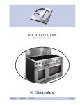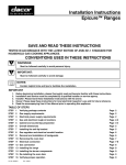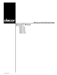
1
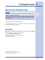
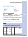
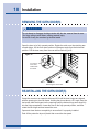
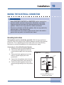
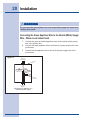
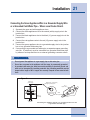
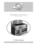
Installation Instructions
Dual Fuel Ranges
E30DF74EPS
E36DF76EPS
E48DF76EPS
5995447082
2 Safety
IMPORTANT SAFETY INSTRUCTIONS
Safety Precautions
Do not attempt to install or operate your unit until you have read the safety
precautions in this manual. Safety items throughout this manual are labeled with a
Warning or Caution based on the risk type.
Definitions
This is the safety alert symbol. It is used to alert you to potential personal
injury hazards. Obey all safety messages that follow this symbol to avoid possible
injury or death.
WARNING
WARNING indicates a potentially hazardous situation which, if not avoided, could
result in death or serious injury.
CA
UTION
CAUTION
CAUTION indicates a potentially hazardous situation which, if not avoided, may result
in minor or moderate injury.
CA
UTION
CAUTION
CAUTION used without the safety alert symbol indicates a potentially hazardous
situation which, if not avoided, may result in property damage.
IMPOR
TANT
IMPORT
Indicates installation, operation or maintenance information which is important but
not hazard related.
Safety
SAFETY PRECAUTIONS
WARNING
•
Read all instructions before using the appliance.
•
Improper installation, adjustment, alteration, service, or maintenance can cause
personal injury or property damage. Refer to these instructions and the
accompanying Use & Care Manual. For assistance or additional information,
consult a qualified installer, service agency, manufacturer (dealer), or the gas
supplier.
•
For your safety:
-
Do not store or use gasoline or other flammable vapors and liquids in the
vicinity of this or any other appliance.
-
Do not obstruct the flow of combustion and ventilation air to the unit.
-
Keep appliance area clear and free from combustible material, gasoline and
other flammable vapors and liquids.
-
Do not use or attempt to use this appliance in the event of a power failure.
•
This unit is designed as a cooking appliance. Never use it for warming or heating
a room.
•
This appliance must not be used in combination with surface (countertop)
ventilation systems. The use of an overhead hood or downdraft is recommended
for ventilation.
•
This appliance must be installed with the gas pressure regulator supplied with it.
•
Disconnect the electrical supply before installing or servicing the appliance.
•
This appliance must be grounded. Connect only to a properly grounded
electrical supply. Refer to “Electrical Requirements”.
•
Install or locate this appliance only in accordance with these installation
instructions.
•
Use this appliance only for its intended use as described in this manual. Do not
use corrosive chemicals or vapors in this appliance. This type of appliance is not
designed for industrial or laboratory use.
•
As with any appliance, close supervision is necessary when used by children.
•
Do not operate this appliance if it has a damaged electrical cord, plug, conduit or
wires, if it is not working properly, or if it has been damaged or dropped.
•
This appliance should be serviced only by qualified service personnel.
•
Some products, such as whole eggs, and sealed containers, such as closed glass
jars, may explode and should not be heated on this cooktop.
3
4 Safety
WARNING
•
Based on safety considerations, the top burner flame should be adjusted so it
does not extend beyond the edge of the cooking utensil.
•
If the information in this manual is not followed exactly, a fire or explosion
may result causing property damage, personal injury, or death.
•
What to do if you smell gas:
•
-
Do not try to light any appliance.
-
Do not touch any electrical switch, do not use any phone in your building.
-
Immediately call the gas supplier from a neighbor’s phone.
-
Follow the gas supplier’s instructions.
-
If you cannot reach your gas supplier, call the fire department.
Installation of this appliance must be performed by a qualified installer, service
agency or the gas supplier.
Finding Information
5
READ AND SAVE THESE INSTRUCTIONS
NO
TE
NOTE
Installer: Leave instructions with owner.
Owner: Read your Range Use & Care Manual. It contains important safety information
for operating this appliance. It also has many suggestions for getting the best results
from your Range.
Read all instructions before installing the Range.
For your safety, please read and observe all safety instructions. This guide will help
you anticipate all installation connections.
QUESTIONS?
For toll-free telephone support in the U.S. and Canada:
1-877- 4ELECTROLUX (1-877-435-3287)
For online support and Internet product information:
www.electroluxusa.com
©2005 Electrolux Home Products, Inc.
Post Office Box 212378, Augusta, Georgia 30917, USA
All rights reserved. Printed in the USA
Attach your sales
receipt to this
page for future
reference.
6 Finding Information
TABLE OF CONTENTS
Safety ................................................................... 2
Definitions .......................................................... 2
Important Safety Instructions .............................. 2
Safety Precautions ............................................. 3
Finding Information ........................................... 5
Please Read And Save This Guide ................... 5
Questions? ........................................................ 5
Table Of Contents .............................................. 6
Preparing for Installation .................................. 7
Verifying Package Contents ............................... 7
Gas Supply Requirements ................................. 7
Gas and Electric Requirements Table ................ 7
Electrical Power Supply Requirements .............. 8
Gas and Electrical Rough-In .............................. 9
Cabinet/Counterop Preparation ....................... 10
Overal Dimensions .......................................... 12
Installing the Anti-Tip Bracket ........................... 13
Gas Regulator and Electrical
Conduit Location .............................................. 16
Installation ........................................................ 17
Installing the Range Backguards ..................... 17
Removing the Door(s) ..................................... 18
Reinstalling the Door(s) ................................... 18
Making the Electrical Connection ..................... 19
Making the Gas Connection ............................. 22
Installing the Range ......................................... 23
Installing the Burner Components .................... 23
Operation ........................................................... 24
Verifying the Operation .................................... 24
Preparing for Installation
VERIFY PACKAGE CONTENTS
• Use & Care Manual
• Burner Rings
• Broiler Pan/Insert
• Wok Ring
• Anti-tip Bracket
• Simmerplate
• Grate Pack
• Stainless Steel Cleaner
• Griddle
• Roasting Rack
• LP Conversion Kit
• Burner Cap Pack
GAS SUPPLY REQUIREMENTS
Check your local building codes for the proper method of installation. In the
absence of local codes, this appliance should be installed in accordance with the
National Fuel Gas Code ANSI Z223.1. Be certain that the appliance being installed
is correct for the gas service being provided. Refer to the rating label located on the
kick panel and/or the table below for gas supply requirements.
GAS AND ELECTRIC REQUIREMENTS TABLE
Refer to the following table for more information on gas and electric requirements.
NO
TE
NOTE
This range is shipped from the factory pre-set for use with natural gas. For LP
conversion see the accompanying LP Conversion Kit. The electrical information in the
table is also located on the serial number label on the range. It can be found by
opening the oven door and looking through the inlet air cooling grill.
Model No.
E30DF74EPS
E36DF76EPS
E48DF76EPS
Electrical
circuit
required
Total
connected
load
240-4
Wire VAC,
60Hz, 30A
26.4 Amps
(6.3 Kw)
240-4
Wire VAC,
60Hz, 30A
26.4 Amps
(6.3 Kw)
240-4
Wire VAC,
60Hz, 50A
44.2 Amps
(10.4 Kw)
Gas type
Manifold
pressure
Minimum gas
supply
pressure
Natural
4” Water Column
5” Water Column
Liquid Propane 10” Water Column 11” Water Column
Natural
4” Water Column
5” Water Column
Liquid Propane 10” Water Column 11” Water Column
Natural
4” Water Column
5” Water Column
Liquid Propane 10” Water Column 11” Water Column
7
8 Preparing for Installation
ELECTRICAL POWER SUPPLY REQUIREMENTS
It is the owner’s responsibility to ensure that the electrical connection of this
appliance is performed by a qualified electrician. The electrical installation,
including minimum supply wire size and grounding, must be in accordance with the
National Electric code ANSI/NFPA 70- 1993* (or latest revision) and local codes and
ordinances.
*A copy of this standard may be obtained from:
National Fire Protection Association
1 Batterymarch Park
Quincy, Massachusetts 02269-9101
The correct voltage, frequency, and amperage must be supplied to the appliance
from a separate, grounded, circuit that is protected by a properly sized circuit
breaker or time delay fuse.
Refer to the Gas and Electrical Requirements Table on page 7.
WARNING
If the gas or electric service provided does not meet the product specifications, do not
proceed with the installation. Call the selling dealer, the gas supplier, or a licensed
electrician.
NO
TES
NOTES
The power supply must be properly polarized. Reverse polarity will result in
continuous sparking of the electrodes, even after flame ignition.
If there is any doubt as to whether the power supply is properly polarized or grounded,
have it checked by a qualified electrician.
Preparing for Installation
GAS AND ELECTRICAL ROUGH-IN
Locations
NO
TE
NOTE
The shaded areas shown in the illustrations, denote the location of the gas stub and the
electrical junction box/receptacle. These are suggested locations. For replacement
purposes, the location of the existing utilities may be utilized provided that they do not
interfere with the sides or rear of the range. If installing the gas valve behind the range,
verify that local building codes will permit this.
A manual shut valve must be installed in the gas piping, external to the appliance,
for the purpose of turning on or shutting off gas to the appliance. Plan the location
of the range and the gas supply to allow access to the valve when the unit is
installed. Access to the remote circuit breaker panel/fuse box, with the range in
place, must also be allowed for in the installation. Any openings in the wall behind
the appliance and in the floor under the appliance must be sealed.
Both the gas supply piping and shut-off valve, and the electrical junction box/
receptacle must be located so they do not interfere with the range when it is
installed. In addition, the junction box must be located so the range can be removed
for service when the conduit supplied with the unit is attached to the junction box.
Do not lengthen the conduit or wiring provided with the range.
All dimensions shown are based on standard American cabinets 36 inches
(914mm) high at the finished countertop by 24 inches (610mm) deep, with a 25
inch (635mm) overall countertop depth. When installing the range into nonstandard
cabinets, minimum clearances shown in the diagrams on page 11 must be
maintained.
Carefully check the location where the range is to be installed. For best
performance, the range should be placed away from drafts that may be caused by
doors, windows and HVAC outlets.
9
10 Preparing for Installation
CABINET AND COUNTERTOP PREPARATION
NO
TES
NOTES
•
•
•
•
•
If cabinet storage space is to be provided directly above the range, the risk of
personal injury may be reduced by installing a ventilating hood that projects
horizontally a minimum of 5 inches beyond the face of the cabinets.
The range may be installed flush to the rear wall. We recommend installing a
non-concombustible material on the rear wall above the range and up to the vent
hood. It is not necessary to install non-combustible materials behind the range
below the countertop height.
The minimum distance from the sides of the range above the countertop to
combustible side walls must be at least 10 inches.
The E36DF76EPS and E48DF76EPS ranges are delivered with a 3” backguard from
the factory. 9” and 24” backguards are available as options. The E30DF74EPS
range is delivered with a 6” backguard from the factory. 9” and 12” backguards
are available as options.
Utilities may be located: In the lower left corner of the adjacent right cabinet.
(Recommended)
IMPOR
TANT
IMPORT
•
Contact your local building department to verify compliance with local code
interpretation.
Preparing for Installation
11
Plan the installation so that the electrical connection, gas shut-off valve, and
pressure regulator are accessible from the front of the cabinet.
Figure 1
E30DF74EPS, E36DF76EPS and
E48DF76EPS
Cutout Dimensions
Model
“A”
“B”
E30DF74EPS
36” (914mm) Recommended
30” (762mm) Minimum
30 1/16” (764mm)
E36DF76EPS
42” (1067mm) Recommended
36” (914mm) Minimum
36 1/16” (914mm)
E48DF76EPS
54” (1372mm) Recommended
48” (1219mm) Minimum
48 1/8” (1222mm)
12 Preparing for Installation
OVERALL DIMENSIONS
E36DF76EPS and E48DF76EPS Overall Dimensions
Side View
Figure 2
E30DF74EPS Overall Dimensions
Side View
Figure 3
Preparing for Installation
13
INSTALLING THE ANTI-TIP BRACKET (FOR 30”, 36” &
48” MODELS)
WARNING
The 30”, 36” and 48” ranges require an anti-tip device. Before installing the range, you
must locate and secure the anti-tip bracket to the floor.
Installation of E30DF74EPS Anti-Tip Bracket
Top View
Location of the E30DF74EPS Anti-Tip Bracket
Figure 4
Figure 5
14 Preparing for Installation
INSTALLING THE ANTI-TIP BRACKET (FOR 30”, 36” &
48” MODELS)
WARNING
The 30”, 36” and 48” ranges require an anti-tip device. Before installing the range, you
must locate and secure the anti-tip bracket to the floor.
Installation of E36DF76EPS Anti-Tip Bracket
Top View
Back wall
Figure 6
7 1/2"
(191mm)
4 13/16" (122mm)
24" (610mm)
18 1/32"
(458mm)
36 1/16"
(916mm)
All Dimensions are
from Cabinet Only
(Not Countertop)
Figure 7
Rear
Leveler
5/16 - 18 x 2
or Equivalent
Left
Rear
Leg
Location of the E36DF76EPS Anti-Tip Leveler
Preparing for Installation
15
INSTALLING THE ANTI-TIP BRACKET (FOR 30”, 36” &
48” MODELS)
WARNING
The 30”, 36” and 48” ranges require an anti-tip device. Before installing the range, you
must locate and secure the anti-tip bracket to the floor.
Installation of E48DF76EPS Anti-Tip Bracket
Top View
Figure 8
Figure 9
Location of the E48DF76EPS Anti-Tip Leveler
16 Preparing for Installation
GAS REGULATOR AND ELECTRICAL CONDUIT
LOCATION
Figure 10
Factory installed
3/4" regulator
(1/2" supply ok)
Power cord
Gas Regulator and Electrical Conduit Location
Rear View
Installation
INSTALLING THE 30”, 36” & 48” RANGE OPTIONAL
BACKGUARDS
Your Electrolux IconTM range was shipped with a backguard in place. These
instructions cover the installation of one of the optional backguards.
WARNING
Be sure that the range is not connected to gas or power before proceeding.
Installing the Range Optional Backguard:
1. Remove the backguard from its box.
2. To avoid scratches, place small scraps of thin cardboard on the rear of
the side panels where the backguard will make contact. With the
assistance of at least one other person, carefully lift the backguard and
place down on to the range top. Special attention should be given to the
lower flange in front of the backguard, which must fit between the
stainless steel side panels.
3. Fasten the provided screws through the rear flange.
4. Connect the gas line to the regulator. Reposition and attach the access
panel or the back cover if the entire back cover was removed.
5. You are now ready to continue with the range installation.
Figure 11
Figure 12
Backguard Installation
(36” range shown)
Backguard Installation
(48” range shown)
NO
TE
NOTE
For 24” Backguards, fasten the provided screws through the holes in the back panel of
the Backguard.
17
18 Installation
REMOVING THE OVEN DOOR(S)
WARNING
Do not attempt to disengage the hinge catches with the door removed from the oven.
The hinge springs could release causing personal injury.
Do not lift or carry the oven door by the door handle.
Open the door to its fully opened position. Rotate the catch over the retaining arm
on each hinge. Lift the oven door to about a 30 degree angle from the horizontal
position. Pull the door away from the oven while continuing to lift.
Figure 13
To remove
oven door,
rotate catch
as shown.
Removing the Oven Door
RE-INSTALLING THE OVEN DOOR(S)
Grasp the oven door on opposite sides and lift it until the door hinges are aligned
with the openings in the oven frame. Holding the door at about a 30° angle from the
horizontal, slide the hinges into the openings until the bottom hinge arms drop fully
into the hinge receptacles. Lower the door to the fully opened position, and then
rotate the two hinge catches toward the oven.
Open and close the door completely to ensure that it is properly installed.
Peel off the protective layer of plastic that covers the door panel.
Installation
19
MAKING THE ELECTRICAL CONNECTION
WARNING
•
Models E30DF74EPS, E36DF76EPS and E48DF76EPS must be connected to a
grounded, metallic, permanent wiring system. Alternatively, a grounding
conductor should be connected to the grounding terminal or lead on the
appliance. Failure to do so may result in an electric shock hazard.
•
Do not use an extension cord with this appliance. Such use may result in fire,
electrical shock, or other personal injury.
•
Do not install a fuse in the neutral or ground circuit. A fuse in the neutral or
ground circuit may result in an electrical shock hazard.
Grounding Instructions
This appliance must be electrically grounded. With the range positioned
directly in front of the cabinet cutout, feed the appliance conduit to the electrical
junction box. Then, depending upon local codes, utilize one of the following
techniques to connect the appliance to the electrical power supply:
Connecting to a Four-Wire Electrical System
1. Separate the green and white appliance wires.
2. Connect the white appliance wire to the
neutral (white) supply wire in the junction
Figure 14
box.
3. Connect the black appliance wire to the
black (L1) power supply wire in the
junction box.
4. Connect the red appliance wire to the red
(L2) power supply wire in the junction box.
5. Connect the green appliance wire to the
green house grounding wire in the junction
box.
Cable from
power supply
Junction
box
RED
RED
WHITE
WHITE
GREEN
GREEN
BLACK
BLACK
Wire nut
(4 places)
Conduit from
appliance
Connecting the appliance to a
four-wire power supply
20 Installation
WARNING
Do not connect the green appliance wire to the neutral (white) supply wire unless local
building codes permit.
Connecting the Green Appliance Wire to the Neutral (White) Supply
Wire – Where Local Codes Permit
1
2
3
Figure 15
Connect the green and white appliance wires to the neutral (white) supply
wire in the junction box.
Connect the black appliance wire to the black (L1) power supply wire in the
junction box.
Connect the red appliance wire to the red (L2) power supply wire in the
junction box.
Cable from
power supply
Junction
box
RED
RED
GREEN
WHITE
WHITE
BLACK
BLACK
Wire nut
(3 places)
Conduit from
appliance
Connecting the appliance to a
three-wire power supply
Installation
21
Connecting the Green Appliance Wire to a Grounded Supply Wire
or a Grounded Cold Water Pipe – Where Local Codes Permit.
1
2
3
4
5
6
Separate the green and white appliance wires.
Connect the white appliance wire to the neutral (white) supply wire in the
junction box.
Connect the black appliance wire to the black (L1) power supply wire in the
junction box.
Connect the red appliance wire to the red (L2) power supply wire in the
junction box.
Connect the green appliance wire to a grounded supply wire in the junction
box or to a grounded cold water pipe.
If connecting to a grounded cold water pipe, a separate copper grounding
wire (No. 10 minimum) must be connected to a grounded cold water pipe
by means of a clamp and then to an external grounding connector screw.
WARNING
•
Do not ground the appliance to a gas supply pipe or hot water pipe.
•
Do not turn on power to the appliance until the range is permanently grounded.
•
A grounded cold water pipe must have metal continuity to electrical ground and
must not be interrupted by insulating materials. Any insulating materials must be
jumped with a length of No. 4 copper wire securely clamped to bare metal at both
ends.
Figure 16
Cable from
power supply
Junction
box
RED
RED
GREEN
GREEN
Separate No. 10 (minimum)
copper grounding wire
No. 4
copper wire
Meter
WHITE
WHITE
Clamp must be
tight on pipe
BLACK
BLACK
Wire nut
(4 places)
Conduit from
appliance
Metal
water pipe
Clamps
Bare metal
Connecting the appliance ground to a grounded junction box wire
or grounded cold water pipe
22 Installation
MAKING THE GAS CONNECTION
Before sliding the range into the cabinet, connect a flexible gas connector to the
gas shut-off valve previously installed on the stub out. The gas valve must be
turned off during installation. Connect the flex connector to the pipe fitting at the
right rear of the range.
WARNING
•
•
•
•
•
Do not apply excessive pressure when tightening gas connections and fittings.
Do not use teflon tape or plumber’s putty on gas flex line connections.
Turn all cooktop control valves to the “OFF” position. Turn on gas supply and
check all lines and connections for leaks using a soap and water solution. Do not
use a flame to check for leaks. After verifying that there are no gas leaks, turn off
the gas supply to the range by turning the gas shut-off valve to the “OFF”
position.
For LP installations, the LP gas tank must have its own high pressure regulator.
This is in addition to the pressure regulator provided with the range.
The maximum gas supply pressure to the regulator must never exceed 1/2 pound
per square inch.
NO
TE
NOTE
The gas pressure regulator is pre-set at the factory for natural gas to use with the
appliance. To convert the range for LP gas, see the instructions supplied in the LP
conversion package.
Installation
INSTALLING THE RANGE
Measure from the floor to the countertop and adjust the leveling legs as required to
position the top frame at the desired height, based on the cabinet and countertop
installation. Carefully slide the range into position in the cutout. The rear anti-tip leg
should engage the anti-tip bracket.
INSTALLING THE BURNER COMPONENTS
Remove the brass burner rings, porcelain burner caps, and porcelain gates from
their shipping packages. Place each burner ring onto its corresponding burner
base, being certain that the four alignment tabs slide into the matching notches in
the base. Set each porcelain burner cap on top of its corresponding burner ring.
Place each grate onto the top frame, being certain that the rubber feet are
positioned in the locating dimples.
WARNING
Never attempt to operate the cooktop section of the range with any of the burner rings,
burner caps or grates removed.
NO
TE
NOTE
Prior to operating the cooktop or oven sections of the range, please read the
accompanying Use and Care Manual carefully. Important safety, service and warranty
information is contained within this manual.
23
24 Operation
VERIFYING THE OPERATION
NO
TE
NOTE
REFER TO THE USE AND CARE MANUAL FOR DETAILED INSTRUCTIONS.
Before beginning the test procedure, ensure that all cooktop control valves are in
the “OFF” position, and all burner rings, burner caps, and grates are properly
positioned on the top frame. Turn on the gas supply at the shut-off valve.
Turn on the power supply to the range. Select a temperature of 350°F by rotating
the temperature control knob to “350” and selecting “BAKE” with the oven selector
knob. Rotate each knob to the “Off” position to stop the heating process. For model
E48DF76EPS, repeat this test procedure with the companion oven. Test each top
burner separately by pressing and turning one control knob at a time
counterclockwise to the “HIGH” position. All ignitors will spark continuously, but only
the burner with gas flowing to it will ignite. (It will take approximately 4 seconds for
ignition to occur, at which time the ignitors will stop sparking. If ignition does not
occur within 4 seconds, turn off the knob, wait for at least 2 minutes to allow any
gas to dissipate, then repeat this ignition test.) The control knob can then be rotated
counterclockwise from “HIGH” to “LOW” to adjust the flame height progressively.
Repeat the ignition test for all burners. When installed properly, the flame will be
steady and quiet. It will also have a sharp, blue inner cone that will vary in length
proportional to the burner size.
WARNING
•
The range and shut-off valve must be disconnected from the gas supply piping
during any pressure testing exceeding 1/2 psi (3.5kPa).
•
The range must be isolated from the gas supply piping by closing the shut-off
valve during any pressure testing at or below 1/2 psi (3.5 kPa).
NO
TES
NOTES
If either the oven or cooktop does not operate properly, follow these troubleshooting
steps:
•
Verify that power and gas are supplied to the range.
•
Check the electrical connections and gas supply to ensure that the installation
has been completed correctly.
•
If the appliance still does not work, contact an authorized service company. Do
not attempt to repair the appliance yourself. Electrolux is not responsible for
service required to correct a faulty installation.