1
Feature Package 3
TRIAD -S
Installation
a new dimension in business communications
STARPLUS Triad-S
TM
Installation Manual
Part Number: 5050-12
Issue 3.2 - March 2001
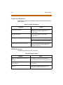
Issue
Release Date
2
8-99
Changes
Feature Package 2 {FP2} enhancements have been added.
Manual content contains extensive revisions.
2.1
12-99
Manual content has been revised.
3
5-00
Manual content has been reformatted.
3.1
8-00
Manual content has been revised.
3.2
3-01
Manual content has been revised for correctness and clarity.
LIFE SUPPORT APPLIC ATIONS POLICY
VODAVI Communications Systems products are not authorized for and should not
be used within Life Support applications. Life Support systems are equipment
intended to support or sustain life and whose failure to perform when properly used
in accordance with instructions provided can be reasonably expected to result in
significant personal injury or death.
VODAVI Communications Systems warranty is limited to replacement of defective
components and does not cover injury to persons or property or other
consequential damages.
Copyright © 2001 VODAVI Technology, Inc.
All Rights Reserved
This material is copyrighted by VODAVI Technology, Inc., and may be duplicated by
Authorized Dealers only. Any unauthorized reproductions, use or disclosure of this
material, or any part thereof, is strictly prohibited and is a violation of the Copyright
Laws of the United States (17 U.S.C. Section 101 et. seq.).
VODAVI reserves the right to make changes in specifications at any time and without
notice. The information furnished by VODAVI in this material is believed to be accurate
and reliable, but is not warranted to be true in all cases.
STARPLUS and TRIAD™ are Registered trademarks of VODAVI Technology, Inc.
mlj/2001
Contents
1
Introduction
Regulatory Information (U.S.A.) ...................................................................... 1-3
Telephone Company Notification .......................................................... 1-3
Incidence of Harm ........................................................................................ 1-3
Changes in Service ....................................................................................... 1-4
Maintenance Limitations ........................................................................... 1-4
Hearing Aid Compatibility ........................................................................ 1-4
UL/CSA Safety Compliance ....................................................................... 1-4
Notice of Compliance ................................................................................. 1-5
Toll Fraud Disclaimer .......................................................................................... 1-5
2
Installation
Introduction ........................................................................................................... 2-3
Site Preparation .................................................................................................... 2-3
General Site Considerations ..................................................................... 2-3
Backboard Installation ................................................................................ 2-5
Verify On-Site Equipment .......................................................................... 2-5
KSU Installation .................................................................................................... 2-6
Mounting the Basic KSU ............................................................................. 2-6
Mounting the Expansion KSU (EKSU) .................................................... 2-9
Battery Charging Unit (BCU) Installation ..................................................... 2-12
KSU Grounding ..................................................................................................... 2-13
Power Line Surge Protection ........................................................................... 2-14
Lightning Protection ................................................................................... 2-14
KSU AC Power Plug ...................................................................................... 2-14
PCB Installation ..................................................................................................... 2-15
PCB Handling and General Installation ................................................ 2-15
BKSU and Main Processor Board Assembly ............................................... 2-15
Modem Unit (MODU) ......................................................................................... 2-16
Miscellaneous Interface Unit (MISU) Installation ..................................... 2-18
DTMF4-A Unit ........................................................................................................ 2-20
Message Wait Unit (MSGU) .............................................................................. 2-21
CKIB/CSIB Installation ......................................................................................... 2-22
CKIB/CSIB Wiring .......................................................................................... 2-23
iv
March 2001
Station Wiring ....................................................................................................... 2-25
Digital Keyset ................................................................................................. 2-25
Single Line Telephone ................................................................................ 2-26
Wall Mounting the Digital Key Telephone ................................................. 2-26
Headset Installation ............................................................................................ 2-28
Caller ID Interface Unit Installation ............................................................... 2-28
Switch Settings .............................................................................................. 2-29
Programming Caller ID ............................................................................... 2-30
SMDR ........................................................................................................................ 2-30
3
System Check-Out
Preliminary Procedures ..................................................................................... 3-3
Power Up Sequence ........................................................................................... 3-3
4
Maintenance and Troubleshooting
System Programming and Verification ........................................................ 4-3
Telephone and Terminal Troubleshooting ................................................ 4-4
Keyset Self Test ..................................................................................................... 4-4
Keyset LCD/LED Test ................................................................................... 4-5
Keyset Button Test ....................................................................................... 4-5
DSS LED/Button Test ................................................................................... 4-6
Key Telephones/Terminals ........................................................................ 4-7
Single Line Telephones .............................................................................. 4-8
DSS/DLS Console .......................................................................................... 4-8
CO Line Card Functions ..................................................................................... 4-9
System Functions ................................................................................................ 4-10
Remote Maintenance ......................................................................................... 4-11
General Overview ......................................................................................... 4-11
Overview of Maintenance Commands ................................................. 4-11
Maintenance Password .............................................................................. 4-11
Exit Maintenance .......................................................................................... 4-12
System Configuration ................................................................................. 4-12
Station Configuration ................................................................................. 4-13
CO Line Configuration ................................................................................ 4-14
Event Trace Buffer ........................................................................................ 4-16
DTMF Receiver Trace ................................................................................... 4-17
March 2001
Remote System Monitor ................................................................................... 4-18
General Overview ......................................................................................... 4-18
Monitor Password ........................................................................................ 4-18
Help Menu (?) ................................................................................................. 4-19
Dump Memory Data .................................................................................... 4-19
Event Trace Mode ......................................................................................... 4-20
Modify Memory Command ...................................................................... 4-22
Exit the Monitor Mode ................................................................................ 4-22
v
vi
March 2001
Figures
Basic KSU ........................................................................................................................... 2-7
Basic KSU Mounting Holes and Installation .......................................................... 2-8
Expansion KSU ................................................................................................................. 2-10
BKSU and EKSU Mounting Holes and Installation .............................................. 2-11
BKSU Dip Switches ......................................................................................................... 2-15
Modem Unit (MODU) .................................................................................................... 2-17
Miscellaneous Interface Unit (MISU) ........................................................................ 2-19
DTMF4-A ............................................................................................................................ 2-20
Message Wait Unit (MSGU) ......................................................................................... 2-21
CKIB Board ......................................................................................................................... 2-22
CSIB Board with MSGU Mounted .............................................................................. 2-23
Digital Station Jack Wiring .......................................................................................... 2-25
Single Line Telephone Wiring .................................................................................... 2-26
Digital Key Telephone Wall Mounting .................................................................... 2-27
Caller ID Cable Connections ....................................................................................... 2-29
Maintenance Help Menu ............................................................................................. 4-12
System Configuration ................................................................................................... 4-12
Station Configuration ................................................................................................... 4-14
CO Line Configuration .................................................................................................. 4-15
Help Menu ......................................................................................................................... 4-19
Trace Mode Status .......................................................................................................... 4-20
Enable Event Trace ......................................................................................................... 4-21
Event Trace ....................................................................................................................... 4-22
viii
March 2001
March 2001
ix
Tables
MISU Dip Switches ......................................................................................................... 2-19
CKIB/CSIB Wiring ............................................................................................................. 2-24
SMDR Printout ................................................................................................................. 2-31
Power Supply Tests ........................................................................................................ 3-3
Flash Rates ........................................................................................................................ 4-5
Key Telephones/Terminals .......................................................................................... 4-7
Single Line Telephone .................................................................................................. 4-8
DSS/DLS Console ............................................................................................................ 4-8
CO Line Loop Start Board (CKIB/CSIB Board) ........................................................ 4-9
System Functions ........................................................................................................... 4-10
Event Trace Buffer Commands .................................................................................. 4-16
x
March 2001
1
Introduction
This manual provides the information necessary to install and
maintain the STARPLUS Triad-S System. The described features are
based on the current software release. If any of these features do not
work on your system, call your sales representative regarding
upgrading your system.
Regulatory Information (U.S.A.)
1-3
Regulatory Information (U.S.A.)
The Federal Communications Commission (FCC) has established rules
which allow the direct connection of the Triad-S System to the telephone
network. Certain actions must be undertaken or understood before the
connection of customer provided equipment is completed.
Telephone Company Notification
Before connecting the Triad-S System to the telephone network, the local
serving telephone company must be given advance notice of intention
to use customer provided equipment and provided with the following
information:
Telephone Numbers
The telephone numbers to be connected to the system.
Triad-S Systems Information
The Ringer Equivalence Number also located on the KSU: 1.3B
The USOC jack required for direct interconnection with the telephone
network: RJ11C
FCC Registration Numbers
For systems configured as a key system: (button appearances)
DLPKOR-24039-KF-E
For systems configured as a Hybrid system: (dial access codes)
DLPKOR-24026-MF-E
Incidence of Harm
If the telephone company determines that the customer provided
equipment is faulty and possibly causing harm or interruption to the
telephone network, it should be disconnected until repairs can be made.
If this is not done, the telephone company may temporarily disconnect
service.
1-4
Regulatory Information (U.S.A.)
Changes in Service
The local telephone company may make changes in its communications
facilities or procedures. If these changes should affect the use of the
Triad-S System or compatibility with the network, the telephone
company must give written notice to the user to allow uninterrupted
service.
Maintenance Limitations
Maintenance on the Triad-S System is to be performed only by the
manufacturer or its authorized agent. The user may not make any
changes and/or repairs except as specifically noted in this manual. If
unauthorized alterations or repairs are made, any remaining warranty
and the software license for the system will be voided.
Hearing Aid Compatibility
All Triad-S Digital Telephones are Hearing Aid Compatible, as defined in
Section 68.316 of Part 68 FCC Rules and Regulations.
UL/CSA Safety Compliance
The Triad-S System has met all safety requirements and was found be in
compliance with the Underwriters Laboratories (UL) 1459. The Triad-S
System is authorized to bear the NRTL/C marking.
Toll Fraud Disclaimer
1-5
Notice of Compliance
The Triad-S System complies with rules regarding radiation and radio
frequency emissions by Class A computing devices. In accordance with
FCC Standard 15 (Subpart J), the following information must be supplied
to the end user:
“This equipment generates and uses RF energy and if not installed and
used in accordance with the Instruction Manual, may cause interference
to Radio Communications. It has been tested and found to comply with
the limits fora Class A computing device, pursuanttoSubpart J of Part15
of the FCC Rules, which are designed to provide reasonable protection
against such interference, when operated in acommercial environment.
Operation of this equipment in a residential area is likely to cause
interference, in which case the user, at his own expense, will be required
to take whatever measures may be required to correct the interference.”
Toll Fraud Disclaimer
“While this device is designed to be reasonably secure against intrusions
from fraudulent callers, it is by no means invulnerable to fraud. Therefore,
no express or implied warranty is made against such fraud including
interconnection to the long distance network.”
“While this device is designed to be reasonably secure against invasion of
privacy, it is by no means invulnerable to such invasions. Therefore, no
express or implied warranty is made against unlawful or unauthorized
utilization which results in the invasion of one’s right of privacy.”
1-6
Toll Fraud Disclaimer
2
Installation
This chapter describes the procedures and steps necessary to install
the Triad-S System.
Introduction
2-3
Introduction
As with any sophisticated communications device, installation of the
STARPLUS Triad-S System requires the care and forethought of a
competent technician. To assure easy servicing and reliable operation,
several factors must be considered when planning the system
installation. The installation proceeds in these major steps:
Site Preparation
KSU and Power Supply (PS) Installation
PCB Installation
System Wiring
Keyset and Terminal Installation
Basic Installation Check-Out
System Programming and Verification
Installing the STARPLUS Triad-S System is quick and efficient if these
installation instructions are followed.
Site Preparation
General Site Considerations
The first step is to locate an acceptable site for the common equipment
(KSUs, boards, etc.). When locating a mounting site for the KSUs, the
following points must be considered:
The KSUs are designed for wall mounting and should not be
mounted directly to a masonry or plasterboard wall. It is
recommended that a 1/2 inch plywood backboard be firmly
mounted to the wall, and the KSU and MDF be mounted to the
backboard.
2-4
Site Preparation
The location must have access to a dedicated 110 Volt AC (±10%), 60
Hz, single-phase circuit with a circuit breaker or fuse rated at 15 amps.
A 3-wire parallel blade grounded outlet should be within
approximately 6 feet of the lower left rear of the BKSU mounting.
The location must have access to a good earth ground, such as a
metallic cold water pipe without non-metallic joints. The ground
source should be located as close as possible to the system.
The system should be located in an area that is well ventilated with a
recommended temperature range of 68°-78° F and a relative
humidity range of 5-60% (non condensing).
The system should be located within 25 feet of the telephone
company’s termination point. Also, the location should be within the
prescribed station loop lengths for all keysets and terminals. If
existing cabling is used, its location and conduits should be
considered. Station wiring should be in the building. Station ports are
not designed for installation outside of the building.
Protection from flooding, flammable materials, excessive dust and
vibration.
The site should be away from radio transmitting equipment, arcwelding devices, copying machines and other electrical equipment
capable of generating electrical interferences.
Operation of this equipment in a residential area is likely to cause
interference. In which case the user, at his own expense, is required to
take any necessary measures to correct the interference.
Site Preparation
2-5
Backboard Installation
A wooden backboard is recommended for all installations and must be
installed when the location has masonry or plasterboard walls. A 1/2-inch
plywood material is sufficient for most installations. The backboard
should be mounted at a convenient height, about three feet above the
floor and be bolted in various places to distribute the weight of the
system.
Space should be available on the bottom side of the backboard for the
MDF cabling and for optional equipment such as a music source, battery
backup, etc. It is recommended that the location of each major item be
roughly sketched on the backboard as an installation layout.
Verify On-Site Equipment
Once the equipment installation site is identified and a dedicated AC
outlet, earth ground, and lighting and ventilation are available, verify that
all equipment required is on-site and was not damaged during shipment.
Unpack the KSUs to assure there is no shipping damage. Note that a
mounting template is packed with the BKSU; this template is required
later in the installation. Check that the type and quantity of boards
received is correct and optional equipment and a Power Line Surge
Protector are on-site. Do NOT unpack the individual boards at this time.
If any equipment is damaged or missing, notify the appropriate
personnel to correct the situation.
2-6
KSU Installation
KSU Installation
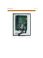
The STARPLUS Triad-S System consists of a Basic KSU (BKSU) cabinet.
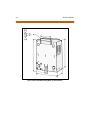
Mounting the Basic KSU
The Basic KSU consists of a plastic cover, a metal base frame designed for
wall mounting. Before installing BKSU on the wall, two wall mounting
plates that are assembled in the bottom side of the BKSU, must be
extended for mounting. The KSU must NOT be mounted on a masonry or
dry-wall surface; a wooden backboard is required.
A mounting template is included with the BKSU. This template can be
used to drill pilot holes for mounting screws. Please note that the
template provides screw hole locations for the BKSU and EKSU. The BKSU
is mounted with three #10 or larger, 1 1/2 inch or longer screws. Drill pilot
holes in the three locations marked, insert the screws and tighten leaving
about 1/2 inch exposed.
KSU Installation
2-7
Figure 2-1: Basic KSU
2-8
KSU Installation
Figure 2-2: Basic KSU Mounting Holes and Installation
KSU Installation
2-9
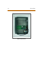
Mounting the Expansion KSU (EKSU)
The Expansion KSU consists of a plastic cover, a metal base frame
designed for wall mount installation. The EKSU contains a power
transformer and expansion interface board (EIB). The EKSU MUST be
mounted above the BKSU. Before installing the BKSU on the wall, the wall
mounting plate that is assembled in the bottom side of the EKSU, must
be extended for wall mounting and the fastener provided with the EKSU
must be assembled with the EKSU.
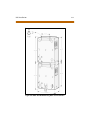
After positioning the EKSU above the BKSU:
1. Mark the location of the two screws to mount the BKSU.The EKSU
must NOT be mounted on a masonry or dry wall surface; a wooden
backboard is required. The EKSU is mounted with two #10 or larger,
1 ½ inch or longer screws.
2. Drill pilot holes in the two locations marked, insert the screws and
tighten leaving about ½ inch exposed.
3. Mount the Expansion KSU on the screws and tighten the screws
securely.
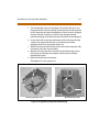
Interconnection is achieved via an amphenol type connector and power
cable. The amphenol connector is included and connects the EKSU to the
BKSU on the right side through connectors labeled EXP as shown:
2-10
KSU Installation
Figure 2-3: Expansion KSU
KSU Installation
Figure 2-4: BKSU and EKSU Mounting Holes and Installation
2-11
2-12
Battery Charging Unit (BCU) Installation
Battery Charging Unit (BCU) Installation
The BCU provides power for the system during a power failure. The BCU
connects to the Triad-S via the connector on the bottom of the BKSU. The
external gel cell batteries must provide 24V DC. This is generally
accomplished by connecting two 12 volt batteries in series.
The BCU provides charging current to the batteries during normal AC
power operation at a maximum of about 0.5 amp. During battery
operation, the BCU discontinues battery operation if AC power is
restored or the battery voltage is too low to maintain proper system
operation.
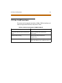
The time the system operates on batteries is dependent on several
elements, including: battery charge state, condition of the batteries,
capacity of the batteries, and the system size (number of station ports).
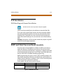
The following chart gives the approximate backup time in ampere hours
for two system sizes and different battery capacities.
Battery Capacity
16 Port
32 Port
10 AH
4 Hour
1.75 Hour
20 AH
8 Hour
3.5 Hour
KSU Grounding
2-13
KSU Grounding
To ensure proper system operation and for safety purposes, a good earth
ground is required. A metallic COLD water pipe usually provides a reliable
ground. Carefully check that the pipe does not contain insulated joints
that could isolate the ground. In the absence of a COLD water pipe, a
ground rod or other source may be used.
A #12 insulated AWG or larger copper wire should be used between the
ground source and the KSU (BKSU and EKSU, respectively). The wire
should be kept as short as possible (recommended 25 feet or less).
1. Remove about 1 1/2 inches of insulation from both ends. Attach one
end of the wire to the Ground Lug on the lower side of the Basic and
on the lower side of the Expansion KSU by inserting the wire under
the lug screw, then tighten the screw securely.
2. Attach the other end of the wire, as appropriate, to the ground
source.
3. Take a DC resistance reading and an AC volt reading between the
chassis ground point (cold water pipe) and AC ground (third wire AC
ground). The limit is 5V AC and 5 Ohms DC resistance. If a higher
reading is obtained, choose a different chassis ground point and
repeat this step until a suitable ground point is found.
2-14
Power Line Surge Protection
Power Line Surge Protection
The AC outlet should be equipped with a power surge protection device
or UPS. Systems using such devices are more resistant to damage from
power line surges than unprotected systems. Power line surges often
occur during normal operations and during violent thunderstorms.
Installation of a surge protector meeting the specifications described in
the following paragraph may prevent or minimize the damage resulting
from power line surges.
The isolation transformer/surge protector should be: 15 amp
self-contained unit that plugs into a standard grounded 117V AC wall
outlet. The wall outlet must be designed to accept a 3-prong plug (two
parallel blades and a ground pin). The protector should be fast and
capable of protecting transients greater than 200 volts.
Lightning Protection
The system provides secondary protection per UL 1459 specifications.
Primary protection circuitry is the installer’s responsibility and should be
installed per the National Electric Code (NEC).
KSU AC Power Plug
Before plugging the KSU power cord into the AC source (grounded,
3-prong AC outlet required):
1. Verify the power switch of the BKSU is off.
2. Plug the KSU power cord into the AC outlet and turn the power
switch on.
The red LED on the MPB illuminates.
PCB Installation
2-15
PCB Installation
PCB Handling and General Installation
DO NOT install or remove any boards with powerapplied.
Power must be turned off prior to installation or removal of the PCBs.
The system cards contain digital circuitry which are extremely reliable,
but can be damaged by exposure to excessive static electricity. When
handling PCBs, a grounded wrist strap should be used to protect the
boards from static discharges. Also, use common sense when handling
PCBs.
Example: Do not place a PCB in locations where heavy objects might fall
on the PCB and damage components.
BKSU and Main Processor Board Assembly
The main processor board (MPB) is installed in the BKSU at the factory
before the shipment. The MPB contains a lithium dry cell to maintain
memory and real-time clock functions. The battery is soldered to the MPB
and connected to the circuitry by an ON-OFF dip switch (SW2). Make sure
the dip switch SW2 is ON before database programming.
Before programming the system, switch 1 (SW1) should be placed in the
ON position and powered off and on to initialize the system database to
default. Once the database is initialized, switch 1 (SW1) should be placed
in the OFF position to protect the database.
Shown below is the dip switch position functions:
MPB PCB Marking
Dip Switch Position
Function
SW1
ON
Flush the database
OFF
Retain the database
Figure 2-5: BKSU Dip Switches
2-16
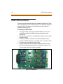
Modem Unit (MODU)
The MPB may be equipped with 3 daughter boards: MODU for modem
access to the system, DTMF-4A for DTMF receiver expansion up to five,
and a MISU for two serial ports and a second music source.
Software for the system is contained on two chips labeled U1 and U2 in
the Program Module Unit (PMU) module.
The MPB provides miscellaneous features:
One external page port that is connected to transformers, providing a
600 ohm impedance.
One music input that is connected to transformers, providing a
600 ohm impedance.
Two independent dry relay contacts rated at 1 amp, 24V DC.
A DTMF receiver.
These features are provided through the amphenol connector on the
front edge of the CKIB installed in the first slot of the BKSU. These features
are controlled by system software.
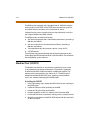
Modem Unit (MODU)
The Modem Unit provides an asynchronous modem for access to the
system database and remote maintenance. The module is optionally
installed on the BKSU’s MPB and includes a 9600 baud modem. The
modem may be accessed from any station or CO. The MODU port is
independent of the MISU RS232C ports, enabling system database
access, etc., without interrupting the SMDR output.
Installing the MODU
1. Using a grounding strap, unpack the MODU from its anti-static bag in
the packing box.
2. Locate the CN6 connector (outlined) on the MPB.
3. Locate the CN1 connector on the MODU.
4. Position the MODU so the CN1 matches with CN6 on the MPB.
5. Push the MODU onto its connector, making sure it is properly seated.
6. Match the screw hole on the MODU PCB bracket with the screw hole
on the base frame.
Modem Unit (MODU)
2-17
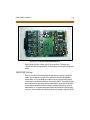
7. Insert a screw and tighten the screws securely.
This completes the MODU installation.
Figure 2-6: Modem Unit (MODU)
The modem may not always connect at 9600 bps. If you encounter a
situation where you cannot connect at 9600 bps, change your
computer’s baud rate to 4800 bps.
2-18
Miscellaneous Interface Unit (MISU) Installation
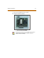
Miscellaneous Interface Unit (MISU) Installation
The Miscellaneous Interface Unit (MISU) contains the second external
music source (MOH/BGM) and two serial ports.
Installing the MISU
1. Using a grounding strap, unpack the MISU from its anti-static
conductive bag in the packing box.
2. Locate the CN15 connector (outlined) on the MPB.
3. Locate the CN3 connector on the MISU.
4. Position the MISU so that CN3 matches CN15 on the MPB.
5. Push the MISU onto it’s connector making sure it is properly seated.
6. Match the screw hole on the MISU PCB bracket with the screw hole
on the base frame.
7. Insert a screw and tighten the screws securely.
This completes the MISU installation.
When the MISU is installed in the Triad-Sand the system is powered
up with dip switches 6 and 7 in the on position, power up will take
about60 seconds.However,if the dipswitches are off, powerupwill
take only 20 seconds.
Miscellaneous Interface Unit (MISU) Installation
2-19
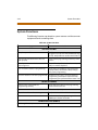
The MISU has an eight position dip switch. The following table lists the
functions of each switch.
Table 2-1: MISU Dip Switches
Dip Switch
Function
1
Not used
2
Not used
3
Not used
4
ON: XOFF/XON
OFF: CTS/RTS
5
Not used
6
ON: Execute H/W tests at start-up
OFF: Skip H/W tests at start-up
7
ON: Display start-up status
OFF: Do not display start-up status
8
Not used
Figure 2-7: Miscellaneous Interface Unit (MISU)
2-20
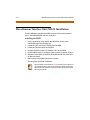
DTMF4-A Unit
DTMF4-A Unit
The DTMF4-A provides an additional four DTMF receivers that may be
used for detecting the DTMF signal from the single line telephone port or
central office line.
Previous DTMFreceivers in the main BKSUcabinetwerenotreliablewhen
using voice mail. The effect was that message waiting notification was
not consistentafter the first notification from an analog voice mail.The
DTMF4-A overcomes the reliability problem of the onboard DTMF
receiverin the main KSU. Also, revision 1D provided a modification that
improved the onboard DTMF reliability .
Installing the DTMF4-A
1. Using a grounding strap, unpack the DTMF4-A from its anti-static
conductive bag in the packing box.
2. Locate the CN13 and CN14 connectors (outlined) on the MPB.
3. Locate the CONN5 and CONN6 connectors on the DTMF4-A.
4. Position the DTMF4-A so CONN5 and CONN6 match CN13 and CN14
on the MPB.
5. Push the DTMF4-A onto its connector making sure it is properly
seated.
This completes the DTMF4-A installation.
Figure 2-8: DTMF4-A
Message Wait Unit (MSGU)
2-21
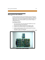
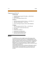
Message Wait Unit (MSGU)
The Message Wait Lamp Relay Control (MSGU) provides message wait
lamp relay control for message lamp single line telephones. The MSGU
board mounts on the CSIB as a daughter-board-type arrangement. The
CSIB interfaces with mechanical 90V AC ringers and 95V DC lights on
2500-type phone sets.
Installing the MSGU
1. Using a grounding strap, unpack the MSGU module from its antistatic conductive bag in the packing box.
2. Locate the CN1 and CN2 connectors on the MSGU module.
3. Locate the CN1 and CN2 connectors on the CSIB (outlined).
4. Position the MSGU module so CN1 and CN2 match CN1 and CN2
connectors on the CSIB, respectively.
5. Push MSGU module onto connectors and ensure it is properly seated.
Figure 2-9: Message Wait Unit (MSGU)
2-22
CKIB/CSIB Installation
CKIB/CSIB Installation
There are two types of expansion boards available: CKIB and CSIB. These
boards include 3 loop start CO line interfaces and 8 digital key telephone
interfaces (CKIB), or 3 loop start CO line interfaces and 8 single line
telephone interfaces (CSIB).
Installing the CKIB/CSIB
1. Using a grounding strap, unpack the CKIB/CSIB from its anti-static
conductive bag and six standoffs from the auxiliary bag in the
packing box.
2. Unscrew the six screws from the CKIB/CSIB installed in the first slot of
the BKSU or EKSU.
3. Insert the standoffs to secure the first card to the BKSU or EKSU.
4. Position the CKIB/CSIB on the six standoffs so the screw holes match.
5. Insert the screws and tighten them securely.
6. Connect the flat cable with the MPB in the BKSU or the EIB in the
EKSU. The CKIB cable is labeled CN4; the CSIB cable is labeled CN5.
This completes the MSGU module installation.
Figure 2-10: CKIB Board
CKIB/CSIB Installation
2-23
Figure 2-11: CSIB Board with MSGU Mounted
Each CKIB or CSIB has 3 loop start CO line interfaces. The loop start
CO/PBX lines are connected to RJ-11 connectors on the right side of each
board.
CKIB/CSIB Wiring
There is one 50-pin female amphenol connector on the left side of the
board. This enables the system to be cabled to the main distribution
frame (MDF). A 25-pair telephone cable must be prepared with mating
connectors to extend the interface circuits to the MDF. The cables should
be routed through the cable clamps at the bottom of the KSU to the MDF.
These cables are terminated on industry standard 66MI-50 type punch
down blocks. It is recommended that 66MI-50 split blocks with bridging
clips be used to simplify troubleshooting and to quickly isolate any faults.
2-24
CKIB/CSIB Installation
Table 2-2: CKIB/CSIB Wiring
Pair Pin #
Color
CKIB
Desc.
CSIB
Desc.
Pair Pin #
Color
CKIB
Desc.
1
26
1
WH/BL
BL/WH
Data-T1 DKTU1 Tip
SLT1
Data-R1
Ring
14
39
14
BK/BN
BN/BK
2
27
2
WH/OR
OR/WH
Data-T2 DKTU2 Tip
SLT2
Data-R2
Ring
15
40
15
BK/SL
SL/BK
3
28
3
WH/GN Data-T3 DKTU3 Tip
SLT3
GN/WH Data-R3
Ring
16
41
16
YL/BL
BL/YL
4
29
4
WH/BN
BN/WH
Data-T4 DKTU4 Tip
SLT4
Data-R4
Ring
17
42
17
YL/OR
OR/YL
5
30
5
WH/SL
SL/WH
Data-T5 DKTU5 Tip
SLT5
Data-R5
Ring
18
43
18
YL/GN
GN/YL
6
31
6
RD/BL
BL/RD
Data-T6 DKTU6 Tip
SLT6
Data-R6
Ring
19
44
19
YL/BN
BN/YL
7
32
7
RD/OR
OR/RD
Data-T7 DKTU7 Tip
SLT7
Data-R7
Ring
20
45
20
YL/SL
SL/YL
EXPIT
EXPIR
8
33
8
RD/GN
GN/RD
Data-T8 DKTU8 Tip
SLT8
Data-R8
Ring
21
46
21
VI/BL
BL/VI
MOHIT
MOHIR
9
34
9
RD/BN
BN/RD
22
47
22
VI/OR
OR/VI
BGM/MOH2T
BGM/MOH2R
10
35
10
RD/SL
SL/RD
23
48
23
VI/GN
GN/VI
RELAY1T
RELAY1R
11
36
11
BK/BL
BL/BK
24
49
24
VI/BN
BN/VI
RELAY2T
RELAY2R
12
37
12
BK/OR
OR/BK
25
50
25
VI/SL
SL/VI
13
38
13
BK/GN
GN/BK
CSIB
Desc.
Wiringfor External Page, MOH/BGM,andRelayis available only atthe firstboard position
of the BKSU.
NOTES
Station Wiring
2-25
Station Wiring
The following provides details on the interconnection of each type
station interface board and station jack.
Only the first pair (green, red) on the jack should be connected to the
KSU. No other pairs should be connected.
Digital Keyset
Wiring from the CKIB to the station jack requires single pair cable (2 or 3
pair is recommended). Digitized voice, signaling and battery are sent
over this pair.
DT
DR
G
Y
R
B
Figure 2-12: Digital Station Jack Wiring
2-26
Wall Mounting the Digital Key Telephone
Single Line Telephone
The CSIB is wired to SLT devices with single pair cabling to provide talk
battery, voice and signaling to and from the SLT.
VT
VR
G
Y
R
B
Figure 2-13: Single Line Telephone Wiring
Wall Mounting the Digital Key Telephone
To wall mount the digital key telephone, it is necessary to use the wall
mount bracket and a standard type jack designed for 630-type wall
hanging applications. Refer to Figure 2-14 on the following page.
1. Remove the handset from the cradle and locate the plastic retainer in
the bottom of the hook-switch well area.
2. Push the plastic retainer slowly upward until it is free.
3. Locate the tab on the plastic retainer, making sure it is toward you,
then place it back into its holder.
4. Slide the plastic retainer all the way down into its channel. Part of the
retainer remains above its holder to hold the handset secure for the
wall mount configuration.
Wall Mounting the Digital Key Telephone
2-27
5. Turn the telephone over and unplug the line cord. If the cord is not
plugged into the wall jack assembly, reroute the line cord through the
access channel on the top of the telephone. If the line cord is plugged
into the wall jack assembly, run the line cord through the hole
provided and plug it into the connector on the back of the telephone.
6. Line up the hooks on the top and bottom of the wall mount bracket
so they can engage with the slots cut into the bottom of the
telephone base. Insert the bottom hooks first.
7. Slide the mounting bracket slowly downwards until the top tabs slide
into the top slots and snap into place.
8. Match the two key hole slots on the base plate with the lugs on the
630-A type jack and align the modular connector, then slide the
telephone into place.
9. Place the handset onto the retainer.
The telephone is now ready to use.
Mounting Bracket Tabs
Wall Mounting Holes
Figure 2-14: Digital Key Telephone Wall Mounting
2-28
Headset Installation
Headset Installation
The STARPLUS Triad-S digital key telephones were designed to operate
with industry standard electret mic compatible modular headset
adapters and operator headsets.
Modifying Digital Telephone to Support External Headset
1. Plug the headset adapter cord into the vacant handset jack on the
key telephone base.
2. Plug the telephone handset cord into the headset adapter box where
indicated by the headset manufacturer’s instructions.
Refer to Station Programming in the System Programming Manual for
instructions on enabling headset operation. After programming, the
station can enable or disable headset mode by dialing a code. When
headset mode is active at the station, the ON/OFF button controls the
on-hook or off-hook status. While headset mode is active, features
such as on-hook dialing and hands free speakerphone operation are
inoperable.
Caller ID Interface Unit Installation
The Caller Identification Interface Unit receives the data from the
telephone company and sends the data, in ASCII RS-232C format to the
KSU.
Connecting the Cable Port (9081-00)
1. Select the correct RS-232 cable.
2. Connect one end of the cable on the desired MSIB I/O port (1 or 2).
3. Connect the other end to the 1480-00 I/O port marked RS232.
Caller ID Interface Unit Installation
2-29
Figure 2-15 illustrates the connections for the TCI Caller ID Interface
Unit.
Triad-S™ MISU
KSU 9-Pin
Female
1480-00 9-Pin
Male
2
5
7
8
Figure 2-15: Caller ID Cable Connections
Switch Settings
S1 dip switches select the signaling protocol of the RS-232 OUT
connector to assist in matching signals from the 1480-00 with those of
the DTE device. S2 dip switches control two major functions:
Switches 1-5 configure the 1480-00 to the DTE device for baud rate,
data bits, and parity.
Switches 6-8 select the unit number for the 1480-00 when multiple
units are connected in series. If a single unit is used, switches 6-8 are
set for Unit #1.
Set the switches on the 1480-00 as follows:
S1
S2
(UP) On
(DOWN) Off
1 2 3 4 5 6 7 8
1 2 3 4 5 6 7 8
2-30
SMDR
Programming Caller ID
ICLID Enable
1. Verify the programming for ICLID enable, ✳✳3226, Flash 56.
2. Press Button [1].
3. Dial [1] on the keypad and press HOLD.
I/O Ports
1. Verify the programming for the I/O ports, ✳✳3226, Flash 15.
2. Select the I/O port, Button 1, 2 (SIU1, SIU2).
3. Dial [5] on the keypad and press HOLD to select 2400 baud.
CO Lines
1.
2.
3.
4.
5.
6.
7.
Verify the programing for the CO lines, ✳✳3226, Flash 40.
Enter the CO line range for the Caller ID Unit.
Press HOLD.
Press Button [21] (Page C).
Press Button [2], ring delay timer.
Enter 04 (minimum) and press HOLD.
Reset the system and Caller ID Unit.
SMDR
The SMDR feature provides detailed records of all outgoing and/or
incoming, long distance only or all calls. The SMDR Qualification Timer
determines the time needed to determine a valid SMDR call for reporting
purposes. By default, this timer is set to 30 seconds and is variable from
00-60 seconds in one second increments. This feature is enabled or
disabled in system programming. By default, SMDR is disabled and set to
record long distance calls only.
A printout format of 80 characters maximum or 30 characters maximum
may be selected in system programming. The standard format is 80
characters per line. A 30 character format generates three lines per
message.
SMDR
2-31
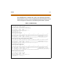
If the SMDR feature is enabled, the system starts collecting information
about the call as soon as it starts and terminates when the call ends. If the
call was longer than 30 seconds, the following information is printed:
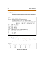
Table 2-3: SMDR Printout
30 ch aracter fo rma t sel ecte d:
1
2
3
123 45 67 89 01 23 45 67 89 01 23 45 67 89 0
AAA A BB B HH :M M: SS H H: MM M M/ DD /Y Y( CR )( LF )
HCC CC CC CC CC CC CC CC CC CC CC CC CC C< R> GG GG GG GG GG GG
STA CO T OT AL
S TA RT
D AT E
111 6 00 8 00 :0 2: 00 1 4: 13 0 8/ 28 /0 0( CR )( LF )
012 34 56 78 90 12 34 56 78 90 12 34 (C R) (L F)
123 45 67 89 01 2( CR )( LF )
80 ch aracter fo rma t sel ecte d:
1
2
3
4
5
6
7
8
123 45 67 89 01 23 45 67 89 01 23 45 67 89 01 23 45 67 89 01 23 45 67 89 01 23 45 67 89 01 23 45 67 89 01 23 45 67 89 0
AAA A BB B HH :M M: SS H H: MM M M/ DD /Y Y HC CC CC CC CC CC CC CC CC CC CC CC C GG GG GG GG GG GG ( CR )( LF )
STA CO T OT AL
ST AR T
DA TE
D IA LE D
A CC OU NT C OD E< _> <_ >C OS T
111 6 00 8 00 :0 2: 00 1 4: 13 0 8/ 28 /0 0 O1 23 45 67 89 01 23 45 67 89 01 23 4 12 34 56 78 90 12 (C R) (L F)
80 ch aracter fo rma t with C all Co st Disp lay feature enab led :
1
2
3
4
5
6
7
8
123 45 67 89 01 23 45 67 89 01 23 45 67 89 01 23 45 67 89 01 23 45 67 89 01 23 45 67 89 01 23 45 67 89 01 23 45 67 89 0
AAA A BB B HH :M M: SS H H: MM M M/ DD /Y Y HC CC CC CC CC CC CC CC CC CC CC CC C GG GG GG GG GG GG ( CR )( LF )
STA CO T OT AL
ST AR T
DA TE
D IA LE D
A CC OU NT C OD E< ~> <~ >C OS T
111 6 00 8 00 :0 2: 00 1 4: 13 0 8/ 28 /0 0 O1 23 45 67 89 01 23 45 67 89 01 23 4
123 45 67 89 01 2< _> 00 0. 00 (C R) (L F)
80 ch aracter fo rma t for D ISA C alls:
1
2
3
4
5
6
7
8
123 45 67 89 01 23 45 67 89 01 23 45 67 89 01 23 45 67 89 01 23 45 67 89 01 23 45 67 89 01 23 45 67 89 01 23 45 67 89 0
AAA A B BB H H: MM :S S HH :M M MM /D D/ YY H CC CC CC CC CC CC CC CC CC CC CC CC G GG GG GG GG GG G (C R) (L F)
STA
C O TO TA L
S TA RT
D AT E
DI AL ED
AC CO UN T CO DE <~ >< ~> CO ST
111 6 00 1 0 0: 02 :0 0 1 4: 13 08 /2 8/ 00 I
12 34 56 78 90 12 <_ >0 00 .0 0( CR )( LF )
001
0 04 0 0: 04 :5 4 14 :1 5 08 /2 8/ 00 I 01 23 45 67 89 01 23 45 67 89 01 23 4
ICL ID 30 chara cter form at selec ted :
1
2
3
123 45 67 89 01 23 45 67 89 01 23 45 67 89 0
STA CO TO TA L
ST AR T
DA TE
100 0 00 1 00 :0 0: 19 0 9: 32 0 8/ 28 /0 0( CR )( LF )
O 48 0- 44 3- 60 00 (C R) (L F)
123 45 67 89 01 2
** (C R) (L F)
2-32
SMDR
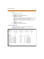
Table 2-3: SMDR Printout
ICL ID 80 chara cter form at selec ted :
1
2
3
4
5
6
7
8
123 45 67 89 01 23 45 67 89 01 23 45 67 89 01 23 45 67 89 01 23 45 67 89 01 23 45 67 89 01 23 45 67 89 01 23 45 67 89 0
STA CO TO TA L
ST AR T
DA TE
D IA LE D
A CC OU NT C OD E< _> <_ >C OS T
100 0 00 1 00 :0 0: 36 0 4:3 7 08 /2 8/ 00 I 1- 48 0- 44 3- 60 00
* *( CR )( LF )
* *V OD AV I
( CR )( LF )
0 1 00 :0 0: 00 0 4: 38 0 8/ 28 /0 0 U1 -4 80 -4 43 -6 00 0
**
* *V OD AV I
(C R) (L F)
AAA A = St at io n or ig in at or o r Tr un k on D IS A an d Of f- Ne t (C O Li ne ) ca ll s.
BBB = O ut si de l in e nu mb er
HH: MM :S S = Du ra ti on o f ca ll i n Ho ur s, M in ut es a nd S ec on ds
HH: MM = T im e of d ay ( st ar t ti me ) in H ou rs a nd M in ut es
MM/ DD /Y Y = Da te o f Ca ll
H = I nd ic at es c al l ty pe :
I = I nc om in g*
O = O ut go in g
T = T ra ns fe rr ed *
U = U na ns we re d ca ll s fo r IC LI D SM DR c al l re co rd s
CC. .. .C C = Nu mb er d ia le d
GG. .. .G G = La st A cc ou nt c od e en te re d (o pt io na l)
(CR ) = Ca rr ia ge r et ur n
(LF ) = Li ne F ee d
3
System Check-Out
Prior to actual power up and initialization, check out the STARPLUS
Triad-S System to avoid start up delays or improper loading. A
step-by-step checklist is provided for this purpose.
Preliminary Procedures
3-3
Preliminary Procedures
1. Make sure the Basic Key Service Unit (BKSU) is properly grounded to
cold water pipe or earth ground.
2. Verify that all expander modules are firmly seated onto their
connectors.
3. Inspect the MDF for shorted wiring and improper polarity that would
affect the Digital Terminal or DSS console.
4. Make certain the lithium battery switch (SW2) on the MBU of the
BSKU is set to the ON position to enable the battery backup option.
5. Make sure the MDF cables connected to the KSU are secure and are
plugged into the correct position.
Power Up Sequence
The power up sequence involves 1) the proper application of AC power
to the system and 2) defaulting the system. A successful power up is
assured if the installation checklist is followed.
1. Plug the AC power cord of the Key Service Unit into the dedicated
117V AC outlet.
2. Remove the BKSU cover, set SW1 on the MBU to the ON position. Set
(SW2) (BATT) to the ON position.
3. Turn the power switch of the KSU to ON.
4. Set (SW1) on the MBU to the OFF position to retain changes to the
database.
The system is ready for programming. If problems occur, refer to
Chapter 4, Maintenance and Troubleshooting.
Table 3-1: Power Supply Tests
Voltage Destination
Voltage Reading
Test Point Location
117V AC
+117V AC,
±10%
Commercial Power
Source
3-4
Power Up Sequence
4
Maintenance and
Troubleshooting
This chapter provides a guideline for isolating and resolving functional
problems that may be encountered due to improper use or component
failure of the STARPLUS Triad-S Systems. Other failures, such as no dial tone
from the central office, must also be considered as an overall
troubleshooting procedure.
System Programming and Verification
4-3
System Programming and Verification
System operation should be verified as per the programmed customer
database once all customer database programming is completed. A hard
copy of the customer database can be printed from the system and
should be kept on-site and up to date for future reference.
System must be initialized before the customer database is
programmed.
The STARPLUS Triad-SSystems are highly-featured digital switches and, as
such, feature activation can sometimes be mistaken for improper
operation. First, verify all programmable features are enabled for the
phone or function in question. Then compare the suspected improper
operation with the feature operation description to determine which
feature is causing conflict. Be aware that some features can override
others and take precedence in operational priority. Then make the
necessary programming changes in customer database programming to
acquire the desired operation.
If feature operation is not the cause of the suspected problem, then
general troubleshooting procedures should be employed. Use these
basic guidelines to determine the cause of a reported problem:
1. Verify that system programming is correct and that the suspected
feature, circuit or function was enabled in programming.
2. Check the installation cabling/wiring and connectors for cuts, shorts
or loose connections.
By verifying correct operation for each segment of the installation
and system, the source of the problem is isolated and can thereby be
identified and resolved.
4-4
Telephone and Terminal Troubleshooting
Telephone and Terminal Troubleshooting
This section discusses general functions on a variety of key telephones
and terminals available for use on the system. It is assumed that basic
troubleshooting skills in the identification and resolution of basic
problems are already possessed (e.g., static/noise heard on conversation,
one phone only; Replace worn handset cord).
Keyset Self Test
The STARPLUS Triad-S System contains a test mode feature that supports
the off-line testing of digital keysets and DSS units. The term off-line
means that the unit under test is operationally disconnected from the
switch during the test operation. Keysets not under test continue to
operate in the normal manner. Tests are provided to verify the keyset and
DSS LED, LCD, and keyboard button operations.
The test mode is entered by taking a keyset’s handset off hook.
Pressing the SPEED button and dialing [7#] on the dial pad
disconnects the keyset from the system and brings up the Test Mode
Menu on the keyset’s LCD. The test mode is exited by putting the
handset back on hook. This reconnects the keyset to the system.
Test Mode Menu -- The menu allows the operator to select a test mode
by pressing the mode number at the dial pad. The operator can always
return to the main test menu by pressing [##].
S ELEC T 1: LCD LED 2: K EY B TN 3 : DS SB TN
Keyset Self Test
4-5
Keyset LCD/LED Test
This test outputs a series of continuously repeated LCD string messages
to LCD lines 1 and 2. The set of strings consists of the letters A through X
and a through x. The next set of strings are:
“P ICK U P TR U CK S PE ED Z ON E ! ”
“* * * STAN D IN G B AC K * ** ”
The strings are alternately displayed on lines 1 and 2 of the LCD display.
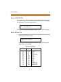
Keyset Button Test
1. Press a keyset button to turn on the LED and display an LCD message
identifying the button number.
PR ES S KE YS ET B U T TON S
DIG IT 1
<- - -- -- - -
Each time the selected button is pressed it sequences through the
table of flash rates available.
Table 4-1: Flash Rates
Button
IPM
Type
01
02
03
04
05
06
07
08
09
10
11
12
13
14
On
30
60
60
240
240
480
480
15
120
120
30
480
480
Steady
Flash
Flash
Double Wink
Flash
Flutter
Flash
Flutter
Flash
Flash
Flutter
Double Flash
Double Wink
Double Flash
4-6
Keyset Self Test
2. Press the dial pad keys to display an LCD message that indicates
which digit was pressed.
Depressing the H-T-P switch from one position to another displays
one the following words: H_POS, T_POS, or P_POS.
3. Test LEDs independently of the Keys by pressing the flex LED button.
DSS LED/Button Test
When the DSS test is selected and a DSS test is invoked, ALL DSS units
associated with the keyset are placed in the test mode.
P RE SS D SS B U T TON S
<-- - -- - -- - -
If no DSS unit is associated with the keyset, the keyset display indicates
NO DSS. The DSS LED test causes all the LEDs to light steady. All LEDs
remain lit steady until a DSS flex button is pressed. Pressing a DSS button
turns on the DSS button LED and displays an LCD message on the
associated keyset identifying the DSS button number (01 to 48). This
button also turns off the previously selected flex LED.
P RE SS D SS B U T TON S
B TN 01
<- -- - -- - -- -
Conditions
Test mode interrupts the normal operation of a keyset or DSS.
Keyset Self Test
4-7
Key Telephones/Terminals
The following actions apply to multi-line key telephones:
Table 4-2: Key Telephones/Terminals
Symptom
Action
No power to keyset
Verify that keyset is connected to correct type
of station card.
No handsfree answer-back on intercom
On digital keysets, the mode of intercom
answer is programmable.
CO line/station button will not access CO
line/station
Check flexible button programming for that
button.
Speakerphone does not work
Check station programming for
speakerphone enable.
Verify phone is a speakerphone model.
Cannot call another intercom station
Check off hook preference programming.
No camp-on signals or override to phone
Check station programming for override
enable
4-8
Keyset Self Test
Single Line Telephones
The following applies to all 2500 type single line telephones connected
to the system.
Table 4-3: Single Line Telephone
Symptom
Action
Phone will not dial out
Verify correct SLT type programmed in station
identification. Verify line group access
programming.
No ringing to phone
Check CO line ringing assignments in
programming.
Message waiting lamp does not work
Check station ID assignment in programming.
Make sure the MSGU is installed on the CSIB.
Cannot call another intercom station
Check off hook preference programming. Put
all unused CO lines in a CO line group not
currently being used.
DSS/DLS Console
The following applies to DSS/DLS Consoles:
Table 4-4: DSS/DLS Console
Symptom
Action
Buttons on DSS/DLS do not function as
labeled
Check station identification assignment in
programming for correct DSS map assignment.
Pressing buttons on DSS does not
activate keyset
DSS must be assigned to keyset in station ID
programming.
No power
Verify unit is connected to the correct type
station board (digital or electronic).
CO Line Card Functions
4-9
CO Line Card Functions
The system can be equipped with either a CKIB or CSIB line interface card.
Each card type contains three (3) Loop Start CO lines.
Table 4-5: CO Line Loop Start Board (CKIB/CSIB Board)
Symptom
Action
3 loop start CO lines on the system do not
work
Check or change card. Check CO line
demarcation.
CO line(s) does not ring
Check CO line ring assignment in
programming.
Noise or cross-talk on the line
Check CO line at demarcation for cross-talk.
Check with different card at different station.
4-10
System Functions
System Functions
The following functions are related to system resources and the common
equipment boards controlling them.
Table 4-6: System Functions
Symptom
Action
Basic KSU and MBU
Complete system failure
Verify that power switch is on, power cord is
plugged in. Check power LED on MBU (left edge
of card). Verify PMU was installed with software.
Any correctly activated feature does not
work properly
Check system programming related to specific
feature.
Loss of system intercom dial tone and call
processing tones
Check off hook preferences, headset mode, and
verify on another telephone.
Loss of customer database programming
Verify status of initialization switch, database
backup battery connection, battery voltage,
and system programming.
Customer database cannot be programmed Verify that no one else is accessing database
programming. Check RS232 cable and verify
programming was performed from Station 100.
Modem Unit (MODU)
Cannot access system database
programming remotely
Verify modem installation and programming.
Check modem baud rate.
Miscellaneous Interface Board (MISU)
Music Channel 2 is not functioning
Verify MSU is installed and check music source.
Cannot communicate with external devices
Check the baud rate programming and the
COMM port selection and cable.
DTMF Receiver Unit (DTMF-A)
DTMF single line telephones cannot dial out Verify DTMF-A is installed.
Remote Maintenance
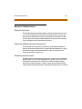
4-11
Remote Maintenance
General Overview
The Remote Maintenance feature allows authorized personnel to survey
system, slot configuration information and programming. This can be
done through the optional modem or data terminal connected via the
RS-232C port on the optional MISU Module. The commands are entered
from a keyboard and are limited to those listed.
Overview of Maintenance Commands
There are four basic commands available in the Remote Maintenance
feature. All commands begin with a single character, followed by a space,
another character and an optional digit or digits. All commands are
terminated with the <Enter> key.
Maintenance Password
The Maintenance feature, like Programming, is entered via a six-character
alphanumeric string. The password prompt is given by pressing <Enter>
at the device connected to the RS232 port. After the prompt displays,
enter the password, then press <Enter>. Proper entry of the password
displays the maintenance prompt. The Maintenance password is: CONFIG
4-12
Remote Maintenance
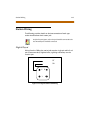
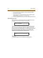
Exit Maintenance
The Exit command terminates the current Maintenance feature session.
The Exit command format is: maint>x
Figure 4-1: Maintenance Help Menu
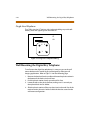
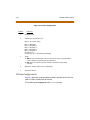
System Configuration
Figure 4-2 is a configuration of the STARPLUS Triad-S System and displays
what is printed when the installer types d<space>s at the maint>
prompt.
.
Figure 4-2: System Configuration
Remote Maintenance
4-13
Where:
Column 1 lists the card slot.
Column 2 lists card type of that card slot.
Column 3 lists card status:
OOS status can indicate the entire card is out of service, or a specific
station is not installed or installed but not operational.
INS status can indicate a specific station is installed and operating
correctly.
Column 4 lists card options.
Column 5 lists firmware version of card.
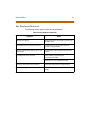
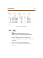
Station Configuration
Figure 4-3 illustrates what is printed out when the installer types
d<space>s1 at the maint> prompt.
4-14
Remote Maintenance
Figure 4-3: Station Configuration
Column
Indicates:
1
Station Number
2
Station Type (keyset, DSS, SLT )
Keyset - ID 0 = Key station
DXX 1 = DSS Map 1
DXX 2 = DSS Map 2
DXX 3 = DSS Map 3
DXX 4 = DSS Map 4
DXX 5 = DSS Map 5
SLT - ID 6= SLT
SLT w/Lamp - ID 7 = SLT w/Message Waiting
3
Status:
OOS status can indicate the entire card is out of service; a specific station
is not installed; or installed but not operational.
INS status can indicate a specific station is installed and operating
correctly.
4
Whether or not the station has an LCD Display
5
State of the device
CO Line Configuration
Figure 4-4 illustrates a representation of what is printed out for slot two
when a LCOB is installed in that slot and:
The installer types d<space>s2 at the maint> prompt.
Remote Maintenance
4-15
Figure 4-4: CO Line Configuration
Column
Indicates:
1
CO Line Number
2
Status:
OOS status can indicate the entire card is out of service.
INS status can indicate a board station is in-service and operating
correctly.
Incoming = Incoming CO line calls are allowed
Outgoing = Outgoing CO line calls are allowed
Bothway = Both incoming and outgoing CO line calls are allowed
For example, Outgoing Enabled indicates the CO line is active in the system.
Outgoing Disabled indicates that the Attendant has disabled the CO line for
outgoing access.
3
Whether CO Line is Pulse or DTMF (programmable option)
4
Whether CO Line is a CO Line or a PBX Line (programmable option)
5
CO line State
4-16
Remote Maintenance
Event Trace Buffer
The Event Trace Buffer is used to store and dump event traces (up to 30)
that occur just prior to a STARPLUS Triad-S System soft or hard restart.
These can then be reviewed by authorized personnel to aid in system
troubleshooting.
The basic format for the commands are as follows:
Table 4-7: Event Trace Buffer Commands
Command
Function
t<space> <return>
Displays the current status of the Event Trace Buffer.
t<space> 0<return>
Turns the Trace buffer OFF.
t<space> 1<return>
Turns the Trace buffer ON to record events prior to a soft
system reset.
t<space> 2<return>
Turns the Trace buffer ON to record events prior to a hard
system restart.
t<space> 3<return>
Turns the Trace buffer ON to record events prior to either a soft
reset or a hard system restart.
d<space> e<return>
Dumps Trace Events stored from last system reset (soft or hard).
d<space> b <return>
Permits maintenance personnel to determine the busy status
of all the busy keysets and CO Lines in thesystem,including the
T1 lines.
r<space> sXXX<return>
Permits a specific station to be reset.
r<space> cXXX <return>
Permits a specific CO Line to be reset.
Press the Esc key to abort the Data Dump and return to the maint>
prompt.
Remote Maintenance
4-17
DTMF Receiver Trace
The CONFIG utility allows technicians to take specific DTMF receivers
in/out of service. This is useful for troubleshooting DTMF receiver
problems to isolate a specific DTMF receiver that may be faulty.
1. Connect a PC with communication software to the I/O port 1 on the
MISU.
2. At the ENTER PASSWORD> prompt, type CONFIG and press [ENTER].
Basic Format for Commands:
d<space>r<return> - to display the status of all DTMF receivers in
the system.
The display shows the receiver number, cabinet location, card slot
location, receiver status, and state of the receiver.
Making a Receiver Busy:
d<space>rXX<return> - Where XX is the specific receiver number to
make busy.
Making a Receiver Available:
d<space>rXX<return> - Where XX is the specific receiver number to
make available.
4-18
Remote System Monitor
Remote System Monitor
General Overview
The Remote System Monitor feature provides access to the installed
system for diagnostic purposes. These capabilities benefit service
personnel enabling them to support the end user.
Different levels of access, via password, allows authorized personnel to
trace, monitor and upload critical information directly from the STARPLUS
Triad-S System. This provides a more accurate means of acquiring system
information that leads to a quick resolution of problems that may occur.
This is all done without interfering with ongoing call processing or
normal system operation, and in many cases may be performed without
a site visit. The optional 9600 baud modem is used for remote access.
Capabilities allowed and reserved for this high level troubleshooting
include the following:
Monitor Mode
Enable and Disable Event Trace
Dump Trace Buffer (up-load)
Monitor Password
The Monitor feature, like Maintenance, is entered via a six-character
alphanumeric string. The password prompt is accessed by pressing the
<Enter> key at the PC connected to the MISU. After the prompt displays,
type the password, then press <Enter>. Proper entry of the password
results in the mon> prompt. The Maintenance password is: ETRACE
The Remote Monitor feature is intended for use only under the
guidance and instruction by authorized personnel from VODAVI
TechnicalSupport.Care and caution mustbe observedwhenusingthis
feature as permanent damage to the software structure can occur.
Remote System Monitor
4-19
Help Menu (?)
A convenient Help Menu is provided by typing [?], then pressing
<Enter>. The following screen displays:
Figure 4-5: Help Menu
Dump Memory Data
Three options allow the memory structure to be dumped for viewing.
The options are entered as follows:
c [c] – Dump CO Line memory structure
s [s] – Dump Station memory structure
d [a][a]– Dump a memory address structure
The data obtained from these commands is in hexadecimal format
and is used primarily for manufacturer-level support.
Press the Esc key to abort the Data Dump and return to the mon>
prompt.
4-20
Remote System Monitor
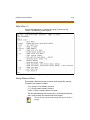
Event Trace Mode
The T command enables and disables the STARPLUS Triad-S System Trace
mode. While the trace mode is enabled events for the trace desired
displays on the monitor, printer or PC connected to the STARPLUS Triad-S
System. To view the current status of the trace mode type [t] and press
<Return> at the mon> prompt, the following screen displays:
Figure 4-6: Trace Mode Status
1. To enable an Event Trace, type t<space> (space bar).
2. Indicate type of trace desired [d], where d is determined as follows:
B = Board event trace (traces events associated with PCB)
M = Miscellaneous State event trace
P = Pulse Coded Modulation (PCM) traces events associated with
voice communications
C = CO Line (LCOB) States (traces events associated with CO Line
activity)
Remote System Monitor
4-21
S = Station (STA) States (traces events associated with Station
activity)
E = Error Messages (traces error messages)
Q = Queue (QUE) Events (traces queuing events: DTMF receiver,
UCD, LCR, etc.)
D = Device Command (traces commands to peripheral devices)
3. Enter the specific board, CO line or Station number of the trace
desired, or type all when all boards, CO lines or Stations events are
desired.
001-012 = CO Line port
100-131 = Station location
All = All Boards, CO lines or Stations
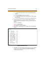
4. Press <Enter> to enable the trace. A screen similar to the following
displays:
Figure 4-7: Enable Event Trace
5. To disable or turn off a particular trace mode, do not enter a specific
board, CO Line or Station Number (e.g.,t<space>s<return> to
disable station event trace).
4-22
Remote System Monitor
To have event traces displayed on the screen, exit the MONitor mode
by typing X at the mon> prompt. After exiting the event(s), the trace
begins as shown in Figure 4-8 .
Unless instructedby personnelatVodaviTechnicalSupport, donot
leave the trace mode enabled for extended time periods. The
systemdumps the requested event(s) trace which may use up
paper or fill memory buffers on the collecting device. It is
recommended that the trace events be disabled (turned off) for all
event(s) traces before leaving the system site unless otherwise
instructed by Technical Support.
Modify Memory Command
The Modify Memory command is for engineering use only.
Usingthis command canalterordamage the Triad-S Systemoperating
databasewhichcan resultinsystemmalfunction.If this occurs,powerthe
systemdownandre-initializethe database,thencompletely reprogram
the customer programmingdata.
Exit the Monitor Mode
The Exit command terminates the current Monitor enable/disable
session. If Event(s) Trace was or is still enabled, event records display only
after exiting the MONitor mode. The Exit command format is: mon> x
Sta
Sta
Sta
Sta
Sta
Sta
Sta
Sta
Sta
Sta
Sta
Sta
Sta
Sta
Sta
Sta
Sta
Sta
Sta
Sta
Sta
Sta
Sta
100:
100:
100:
100:
100:
100:
100:
100:
100:
100:
100:
100:
100:
100:
100:
100:
100:
100:
100:
100:
100:
100:
100:
State=
State=
State=
State=
State=
State=
State=
State=
State=
State=
State=
State=
State=
State=
State=
State=
State=
State=
State=
State=
State=
State=
State=
DIAL_TONE, Evt= Dial Pad (25), Data=7
DIALING, Evt= Dial Pad (25), Data=5
DIALING, Evt= Int Page (69), Data=8
PAGING, Evt= Dial Pad (25), Data=3
PAGING, Evt= Dial Pad (25), Data=9
PAGING, Evt= Dial Pad (25), Data=5
PAGING, Evt= Dial Pad (25), Data=8
PAGING, Evt= Dial Pad (25), Data=7
PAGING, Evt= Dial Pad (25), Data=4
PAGING, Evt= Dial Pad (25), Data=3
PAGING, Evt= Dial Pad (25), Data=9
PAGING, Evt= Dial Pad (25), Data=9
PAGING, Evt= Dial Pad (25), Data=9
PAGING, Evt= Dial Pad (25), Data=7
PAGING, Evt= Dial Pad (25), Data=11
PAGING, Evt= Dial Pad (25), Data=3
PAGING, Evt= Dial Pad (25), Data=2
PAGING, Evt= Page T/O (150), Data=0
MISC_TONE, Evt= Dial Pad (25), Data=4
MISC_TONE, Evt= Dial Pad (25), Data=9
MISC_TONE, Evt= Key Data (26), Data=32
MISC_TONE, Evt= Mon Key (145), Data=-1
MISC_TONE, Evt= On Hook (17), Data=0
Figure 4-8: Event Trace
Index
B
M
Backboard Installation 2-5
Battery Charging Unit Installation 2-12
BKSU/MBU Assembly 2-15
Maintenance Password 4-11
MISU Installation 2-18
Modem Unit (MODU) Installation 2-16
C
P
CO Line Card Functions 4-9
PCB Installation 2-15
Power Line Surge Protection 2-14
Power Up Sequence 3-3
D
DSS LED/Button Test 4-6
DTMF4-A Unit Installation 2-20
Dump Memory Data 4-19
R
E
S
EKSU, mounting 2-9
Site Preparation 2-3
System Check-Out Procedures 3-1
System Commands
DTMF Receiver Trace 4-17
Event Trace Buffer 4-16
Event Trace Mode 4-20
Exit Maintenance 4-12
Exit Monitor Mode 4-22
Modify Memory 4-22
System Functions 4-10
System Programming and Verification
4-3
H
Help Menu (?) 4-19
K
Keyset Button Test 4-5
Keyset LCD/LED Test 4-5
Keyset Self Test 4-4
KSU
AC Power Plug 2-14
Mounting 2-6
KSU, grounding 2-13
L
Lightning Protection 2-14
Remote Maintenance 4-11
T
Telephone and Terminal (Troubleshooting) 4-4
ii
March 2001
we’re talking
technology
www.vodavi.com
©2000 Vodavi Technology, Inc.
VODAVI is a registered trademark of Vodavi Technology, Inc.
5050-12