1
ries
Nine
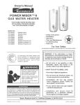
GAS WATER HEATER
USER'SGUIDE
For Your Safety
AN ODORANT IS ADDED TO THEGAS USEDBY THIS
WATER HEATER
WARNING:If the information in these instructions are not followed exactly, a fire or explosion may result, causingproperty
damage,personalinjuryor death.
-Do not storeor use gasolineor other flammablevaporsand liquidsin the vicinityof thisor anyotherappliance.
-WHATTO DOIFYOUSMELLGAS
• Donot try to light anyappliance.
• Do not touch any electricalswitch;do not use any phone in
yourbuilding.
• Immediatelycallyour gas supplierfrom a neighbor'sphone.
Followthe gassupplier'sinstructions.
• If youcannot reachyourgassupplier,callthe fire department.
-Installationand servicemustbeperformedby a qualifiedinstaller,
serviceagencyorthe gassupplier.
•,WARNING
Improper installation,
adjustment,
alteration,
service or maintenance can cause DEATH, SERIOUS BODILY INJURY, OR PROPERTY
DAMAGE.Refer to this manual for assistance or consultthe local
gas utility for further information.
Model Numbers
HN4930T
HP4930T
HN5930T
HP5930T
HN49405
HP49405
HN4940T
HP4940T
HN4950S
HP4950S
HN4950T
HP4950T
HN4975S
HP4975S
HN5940S
HP5940S
HN5940T
HP5940T
HN5950S
HP5950S
HN5950T
HP5950T
HN59755
HP5975S
FOR POTABLE WATER
HEATING ONLY
NOT
FOR
SUITABLE
SPACE HEATING
NOT FOR USE IN
Flammable vapors may be drawn by air currents from other
areas of the structure to AWARNING
this appliance.
t
AWARNING
READ THE GENERAL SAFETY SECTION BEGINNING ON INSIDE
COVER AND THEN THIS ENTIRE MANUAL BEFORE INSTALLING
OR OPERATINGTHIS WATERHEATER.
Save this Manual for Future Reference.
(MOBILE) HOMES
MANUFACTURED
Caution:
Read and Follow All
Safety Rules and
Operating
Instructions
Before First Use of
This Product.
Safety Instructions
•,WARNING
Improper installation, adjustment, alteration, service
or maintenance can cause DEATH, SERIOUS BODILY
INJURY, OR PROPERTY DAMAGE. Refer to this manual for assistance consult your local gas utility or call
Mayta_ Customer Service at 1-800-788-8899 for an
authonzed servicer for further information.
[
AWARNING
I At the time of manufacture this water heater was proIvided with a combination temperature-pressures relief
Ivalve certified by a nationally recognized testing laboI ratory that maintains periodic inspection of production
Iof listed equipment or materials, as meeting the
]requirements for Relief Valves and Automatic Gas
l Shutoff Devices for Hot Water Supply Systems, and
Jthe latest edition of ANSI Z21.22 and the code require-
AWARNING
I requirements of local codes, but not lessthan a combiI nation
temperature
and pressure
relief must
valve meet
certified
ments of
ASME. If replaced,
the valve
the
las meeting the requirements for Relief Valves and
IAutomatic Gas Shutoff Devices for Hot Water Supply I
I Systems, ANSI Z21.22 by a nationally recognized test- I
Iing laboratory that maintains periodic inspection of
I production of listed equipment or materials.
| The valve must be marked with a maximum set pressure not to exceed the marked hydrostatic working
pressure of the water heater (150 Ibs./sq. in.) and a
discharge capacity not less than the water heater
input rate as shown on the model rating plate.
(Electric heaters - watts divided by 1000 x 3415 equal
BTU/Hr. rate.)
WATER HEATERS EQUIPPED FOR ONE TYPE GAS
IONLY: This water heater is equipped for one type
gas only. Check the model rating plate near the gas
control valve for the correct gas. DO NOT USE THIS
WATER HEATER WITH ANY GAS OTHER THAN THE
ONE SHOWN ON THE MODEL RATING PLATE. Failure
to use the correct gas can cause problems which can
result in DEATH, SERIOUS BODILY INJURY, OR PROPERTY DAMAGE. If you have any questions or doubts
consult your gas supplier or local utility,
AWARNING
1
INSTALLATIONS IN AREAS WHERE FLAMMABLE LIQ-|
UIDS (VAPORS) ARE LIKELYTO BEPRESENTOR STORED[
(GARAGES, STORAGE, AND UTILITY AREAS, ETC): I
I Flammable liquids (such as gasoline, solvents, propane _
I
(LP) or butane, etc.), all of which emit flammable|
vapors, may be improperly stored or used in such
areas. The gas water heater pilot light or main burner
can ignite such vapors. The resulting flashback and fire
can cause death or serious burns to anyone in the
area, as well as property damage,
If installation in such areas is your only option, then
the installation must be accomplished in a way that
the pilot flame and main burner flame are elevated
from the floor at least 18 inches. While this may reduce
the chances of flammable vapors from a floor spill
being ignited, gasoline and other flammable substances should never be stored or used in the same
room or area containing a gas water heater or other
open flame or spark producing appliance.
NOTE: Flammable vapors may be drawn by air currents
from other areas of the structure to the appliance,
use of a temperature-pressure relief valve complying
with ANSI Z21.22 and ASME, may require a valve model
different from the one furnished with the water heater.
Your
local jurisdictional
authority,
while mandating
the
Compliance
with such local
requirements
must be sat°
isfied by the installer or end user of the water heater
with a locally prescribed temperature-pressure relief
valve installed in the designated opening in the water
heater in place of the factory furnished valve.
For safe operation of the water heater, the relief valve
must not be removed from it's designated opening or
plugged.
The temperature-pressure
relief valve must be
installed directly into the fitting of the water heater
designated for the relief valve. Position the valve
downward and provide tubing so that any discharge
will exit only within 6 inches above, or at any distance
below the structural floor. Be certain that no contact is
made with any live electrical part. The discharge openJng must not be blocked or reduced in size under any
circumstances.Excessivelength, over 30 feet, or use of
more than four elbows can cause restriction and
reduce the discharge capacity of the valve.
No valve or other obstruction is to be placed between
the relief valve and the tank. Do not connect tubing
directly to discharge drain unless a 6_ air gap is provided. To prevent bodily injury, hazard to life, or property
damage, the relief valve must be allowed to discharge
water in quantities should circumstances demand. If
the discharge pipe is not connected to a drain or other
suitable means, the water flow may cause property
damage.
The Discharge Pipe:
• Must notbe smaller in size than the outlet pipe size
of the valve, or have any reducing couplings or
other restrictions.
• Must not be plugged or blocked.
• Must be of material listed for hot water distribution.
_,WARNING
If this water heater will be used in beauty shops,
barber shops, cleaning establishments, or self-service laundries with dry cleaning equipment, it is
imperative that the water heater or water heaters
be installed so that combustion and ventilation air
be taken from outside these areas. Refer to the
ULocating The New Water Heater" section of this
manual and also the latest edition of the National
Fuel Gas Code, ANSI Z223.1, also referred to as NFPA
54 for specifics provided concerning air required,
i
AWARNING
/A fire can start if_materials
such as
/clothing, cleaning materials, or flammable liquids
[are placed against or next to the water heater.
2
both
temperature-pressure
relief valve,
and
• of
Must
be the
installed
so as to allow complete
drainage
the discharge pipe.
• Must terminate at an adequate drain.
• and
Musttank.
not have any valve between the relief valve
Safety Instructions
AWARNING
AWARNING
A gas water heater cannot operate properly without
the correct amount of air for combustion. Do not
install in a confined area such a closet, unless you
provide air as shown in the ULocating The New
Water Heater" section. Never obstruct the flow of
ventilation air. If you have any doubts or questions
at all, call your gas company. Failure to provide the
proper amount of combustion air can result in a fire
or explosion and can cause DEATH, SERIOUS BODILY
INJURY, OR PROPERTY DAMAGE.
This water heater must not be installed directly on
carpeting. Carpeting must be protected by a metal
or wood panel beneath the appliance extending
beyond the full width and depth of the appliance by
at least 3 inches (76.2mm) in any direction, or if the
appliance is installed in an alcove or closet, the
entire floor must be covered by the panel. Failure to
heed this warning may result in a fire hazard.
_WARNING
AWARNING
VENT DAMPERS - Any vent damper, whether it is
operated thermally or otherwise must be removed if
its use inhibits proper drafting of the water heater.
Thermally Operated Vent Dampers: Gas-fired water
heaters having thermal efficiency in excess of 80%
may produce a relatively low flue gas temperature.
Such temperatures may not be high enough to properly open thermally operated vent dampers. This
would cause spillage of flue gases and may cause
carbon monoxide poisoning.
Vent dampers
must
bear
evidence
of certification
complying
with
the
latest
edition
of Americanas
National Standard ANSI Z21.68 (ANSI Z21,66 & 67,
respectively, cover electrically and mechanically actuated vent dampers). Before installation of any vent
HOTTER WATER CAN SCALD: Water heaters are
intended to produce hot water. Water heated to a
temperature which will satisfy clothes washing, dish
washing, and other sanitizing needs can scald and
permanently injure you upon contact. Some people
are more likely to be permanently injured by hot
water than others. These include the elderly, children,
the infirm, or physically/mentally
handicapped, if
anyone using hot water in your home fits into one of
these• c_roups or if there is a local code or state law
requmng a certain temperature water at the hot
water tap, then you must take special precautions. In
addition to using the lowest possible temperature
setting that satisfies your hot water needs, a means
such as a mixing valve, should be used at the hot
water taps used by these people or at the water
heater. Mixing valves are available at plumbing supply or hardware stores. Follow manufacturers instructions for installation of the valves. Before changing
the factory setting on the thermostat,
read the
"Temperature Regulation" section in this manual.
damper, consult your local gas utility for further
information.
_WARNING
• The appliance and its individual shutoff valve must
be disconnected from the gas supply piping system
during any pressure testing of the gas system at
test pressures in excess ofl/2 pound per square
inch (3.5kPa).
• The appliance must be isolated from the gas supply piping system by closing its individual manual
shutoff valve during any pressure testing of the
gas supply piping system at test pressures equal or
less than 1/2 pound per square inch (3.5kPa).
A, WARNING
Soot build-up indicates a problem that requires correction before further use. Turn "off" gas to water
heater and leave "off" until repairs are made,
because failure to correct the cause of the sooting
can result in a fire or explosion causing DEATH, SERIOUS BODILY INJURY, OR PROPERTY DAMAGE.
-_ WARNING
AWARNING
BEFORE LIGHTING [PROPANE (L.P.) GAS WATER
HEATERS]: Propane (L.P.) gas is heavier than air.
Should there be a leak in the system, the gas will settie near the ground, Basements, crawl spaces, skirted
areas under manufactured (mobile) homes (even
when ventilated), closets and areas below ground
level will serve as pockets for the accumulation of
this gas. Before attempting to light or relight the
water heater's pilot or turning on a nearby electrical
light switch, be absolutely sure there is no accumu-
Chemical vapor corrosion of the flue and vent system may occur if air for combustion contains certain
chemical vapors. Spray can propellants, cleaning solvents, refrigerator and air conditioner refrigerants,
swimming pool chemicals, calcium and sodium chloride, waxes, bleach, and process chemicals are typi-
lated gas in the area. Search for odor of gas by sniffing at ground level in the vicinity of the appliance. If
odor is detected,
follow
steps
indicated
"For leave
Your
Safety"
on the cover
page
of this
manualatthen
the premises.
I
AWARNING
I Obstructed or deteriorated vent systems may pre[sent a serious health risk or asphyxiation.
cal compounds which are potentially corrosive.
3
Safety Instructions continued on page 4.
]
1
Safety Instructions
_,WARNING
AWARNING
The water heater with draft hood installed must be
properly vented to a chimney which terminates outdoors. Never operate the water heater unless it is
vented to the outdoors and has adequate air supply
to avoid risks of improper operation, explosion or
asphyxiation.
INSULATING JACKETS: When installing an external
water heater insulation jacket on a gas water heater:
=DO NOT cover the temperature-pressure relief valve.
=DO NOT put insulation over any part of the top of
the gas water heater.
• DO NOT put insulation over the gas control valve or
gas control valve/burner cover, or any access areas
to the burner.
• DO NOT let insulation around the gas water heater
to get within 8 inches of the floor (air must get to
the burner).
=DO NOT cover or remove operating instructions,
and safety related warning labels and materials
affixed to the water heater.
Failure to heed this will result in the possibility of a
fire or explosion.
AWARNING
Minimum clearances between the water heater and
combustible and noncombustible construction are 1"
at the sides and rear, 4" at the front, and 6" from the
vent pipe. Clearance from the top of the jacket is 18"
on most models. Note that a lesser dimension may be
allowed on some models. Refer to the label on the
water heater adjacent to the gas control valve for all
clearances.
_,CAUTION
WATER HEATERS EVENTUALLY LEAK: Installation
A,WARNING
of
Flood damage to a water heater may not be readily
visible or immediately detectible. However, over a
period of time a flooded water heater will create
dangerous conditions which can cause DEATH, SERIOUS BODILY INJURY, OR PROPERTY DAMAGE.
Contact the Maytag dealer from whom the appliante was purchased or call Maytag Customer Service
at 1-800-788-8899
for an authorized
servicer to
replace a flooded water heater. Do not attempt to
repair the unitl It must be replacedl
the water heater must be accomplished in such a
manner that if the tank or any connections should
leak, the flow of water will not cause damage to
the structure. For this reason, it is not advisable to
install the water heater in an attic or upper floor.
When such locations cannot be avoided, a suitable
drain pan should be installed under the water
heater. Drain pans are available at your local hardware store. Such a drain pan must be not greater
than 1½ inches deep, have a minimum length and
width of at least 2 inches greater than the water
heater dimensions and must be piped to an adequate drain. The pan must not restrict combustion
A,WARNING
air flow. Under no circumstances is the manufacturer or Maytag to be held liable for any water damage in connection with this water heater.
HYDROGEN GAS: Hydrogen gas can he produced in
a hot water system that has not been used for a
long period of time (generally two weeks or more).
Hydrogen gas is extremely flammable and explosive.
] To prevent the possibility of injury under these conditions, we recommend the hot water faucet be
opened for several minutes at the kitchen sink
before any electrical appliances which are connected
to the hot water system are used (such as a dishwasher or washing machine). If hydrogen gas is present, there will probably be an unusual sound similar to air escaping through the pipe as the hot water
faucet is opened. There must be no smoking or open
flame near the faucet at the time it is open.
4
Table of Contents
Safety Instructions .....................................................................................................
2-4
Table of Contents ........................................................................................................
.5
Customer Information ..............................................................................................
.6
Product Specifications ...............................................................................................
7
Accessories and Tools Needed ............................
,...............................................................
.8
Accessories ...................................................................................................................................................................
Tools ...................................................................................................................................................................................
Instructions
for Installation
8
_
.....................................................................................
9-19
Removing the Old Water Heater .....................................................................................................................................
Typical Installation .........................................................................................................................................................
Locating the New Water Heater .................................................................................................................................
Combustion Air and Ventilation for Appliances in Unconfined Spaces .............................................................................
Combustion Air and Venflation for Appliances in Confined Spaces ............................................................................
Water Piping .....................................................................................................................................................................
Temperature-Pressure Relief Valve .................................................................................................................................
Filling the Water Heater ..................................................................................................................................................
Venting .......................................................................................................................................................................
Gas Piping ................................................................................................................................................................
Installation Checklist ..........................................................................................................................................................
.9
..10
11,12
12
12,13
14
15
16
16,17
17,18
19
Instru ct!o n sfor Op er a t!on;????Z?????;;;?;???????;??????
S???Z))?)??:???Z__;;Z;;Z?;;?
?_00_
Temperature
Regulation ....................................................................................................................................................
Service and Maintenance
..........................................................................................
23-25
Venting System Inspection. ..............................................................................................................................................
Burner Inspection .......................................................................................................................................................
L.R Gas Control Valve and Burner Assembly Replacement Information .........................................................................
Burner Cleaning ..............................................................................................................................................................
Draining .........................................................................................................................................................................
Temperature-Pressure Relief Valve Operation .................................................................................................................
Drain Valve Washer Replacement .................................................................................................................................
Housekeeping .................................................................................................................................................................
Service ...........................................................................................................................................................................
Troubleshooting
22
.23
23
224
.24
24
25
.25
.25
25
..........................................................................................................
26-29
Start Up Conditions ..........................................................................................................................................................
Condensation ...........................................................................................................................................................
Smoke/Odor ............................................................................................................................................................
.26
26
26
Thermal Expansion ....................................................................................................................................................
Strange Sounds .........................................................................................................................................................
Operational Conditions ...........................................................................................................................................
Smelly Water .............................................................................................................................................................
Air in Hot Water Faucets ............................................................................................................................................
26
.26
.27,28
27
.27
High Temperature Shut Off System ...........................................................................................................................
Not Enough Hot Water .............................................................................................................................................
Water is too Hot ..........................................................................................................................................................
Leakage Checkpoints ......................................................................................................................................................
27
.27
28
29
---Repair
Parts List ..........................................................................................................
30-37
Warranty ........................................................................................................................
40
5
Customer Information
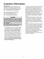
Thank You for purchasing
a Maytag water heater.
• The installation must conform with the instructions in this
manual; gas company rules; and Local Codes, or in the
absence of Local Codes, with the latest edition of the
National Fuel Gas code, ANSI Z223.1, also referred to as
Properly installed and maintained, it should give you years of
trouble free service. It is strongly suggested that this new water
heater be professionally installed, contact Maytag Customer
Service (1-800-788-8899) for recommended installers.
NFPA 54. This publication is available from your local
government or public fibrary or gas company or by writing
NFPA, Batterymarch Park, Quincy, MA 02269.
• After reading this manual you have any questions or do not
understand any portion of the instructions, call Maytag
Customer Service at 1-800-7_8-8899 for an authorized
Abbreviations Found In This Instruction Manual
CSA - Canadian Standards Association
ANSI - American National Standards Institute
NFPA - National Fire Protection Association
servicer,
_WARNING
• Carefully plan the place where you are going to put the
water heater. Correct combustion, vent action, and vent
This gas-fired water heater is design certified by
CSA INTERNATIONAL
under American National
Standard/CSA Standard for Gas Water Heaters ANS
Z21.10.1 • CSA 4.1 (latest edition). The installation
must
conform
this of
manual,
Local Codes
with the
latest with
edition
the National
Fuel and
Gas
Code, ANSI Z223.1.
This publication is available from your local govern-
pipe installation are very important in preventing death
from possible carbon monoxide poisoning and fires.
Examine the location to ensure the water heater complies
with the "Locating the NewWater Heater" section in this
manual.
• For California installation this water heater must be braced,
ment or public library, gas company, or by writing
NFPA, Batterymarch Park, Quincy, MA 02269.
anchored, or strapped to avoid falling or moving during an
earthquake. See instructions for correct installation procedures. Instructions may be obtained from your local dealer,
wholesaler, public utilities or California Office of the State
Architect, 400 P Street, Sacramento, CA 95814.
• Read the "Safety Instructions" sectlon, pages 2, 3 and 4 of
this manual first and then the entire manual carefully. If
you don't follow the safety rules, the water heater will not
operate properl)_ It could cause DEATH, SER/OUS
BODILY INJURY AND/OR PROPERTY DAMAGE.
• This manual contains instructions for the installation,
• Massachusetts Code requires this water heater to be
installed in accordance with Massachusetts 248-CMR 2.00:
State Plumbing Code and 248-CMR 5.00.
operation, and maintenance of the gas-fired water heater.
It also contains warnings through out the manual that you
must read and be aware of. All warnings and all instructions are essential to the proper operation of the water
heater and your safety. Since we cannot put everything on
the first few pages, READ THE ENTIRE MANUAL
BEFORE ATTEMPTING
TO INSTALL OR OPERATE THE WATER HEATER.
• Compiles with SCAQMD rule #1121 and districts having
equivalent NOx requirements.
6
Product Specifications
Model
HN4930T
*HN5930T
HP4930T
*HP5930T
HN4940S
*HN5940S
HP4940S
*HP5940S
HN4940T
*HN5940T
HP4940T
*HP5940T
Tank Capacity
In Gallons
30
30
40
40
40
40
Type of
Gas
B.T.U.
Natural
Propane
Natural
Propane
Natural
Propane
40_000
40,000
407000
40,000
40,000
Rate
Recovery Rate
In Gals Per Hour
@ 90*F Rise
Minimum
40,000
41.0
41.0
41.0
41.0
41.0
41.0
Vent Pipe
Diameter
3" or 4"
16"
3" or 4"
16"
Y' or 4"
20"
3" or 4"
20"
3" or 4"
18"
3" or 4"
18"
Height To
Top of
Draft Hood
62"
62"
52"
52"
62V{'
62t/2"
Model
.
HN4950S
HP4950S
HN4950T
HP4950T
HN4975S
HP4975S
*HN5950S
*HP5950S
*HN5950T
*HP5950T
*HN5975S
*HP5975S
Tank Capacity
In Gallons
50
50
50
50
73
73
Type of
Gas
B.T.U.
Natural
Propane
Natural
Propane
Natural
Propane
Rate
Recovery Rate
In Gals Per Hour
@ 90*F Rise
Minimum
40_000
40,000
40,000
40,000
75_000
55,000
41.0
41.0
41.0
41.0
77.0
56.0
Vent Pipe
Diameter
3" or 4"
24"
3" or 4"
24"
3" or 4"
20"
3" or 4"
20"
4"
24"
4"
24"
Height To
Top of
Draft Hood
531/"
531/,"
63"
63"
621/2"
621/f '
* High altitude models have a B.T.U./Recovery
Rate 10% less than shown.
7
.
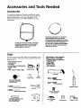
Accessories and Tools Needed
Accessories
To simplify
the installation
May_ag
has available
the installation parts shown below. You may or may not need all of these
accessories
depending
on your type of installation.
Call
Maytag
Customer
Service
at 3.-800-788-8899
for an authorized installer.
C)
DRAIN PANS AVAILABLE IN 22" DIAMETER
(PART NUMBER 66001011) FOR WATER
HEATERS HAVING A DfAMETER 20" OR LESS,
24" DIAMETER (PART NUMBER 66001105) FOR
WATER HEATERS HAVING A DIAMETER 22"
EXPANSION TANKS FOR THERMAL EXPANSION
OR LESS AND 28" DIAMETER (PART NUMBER
66001012) FOR WATER HEATERS HAVING A
DIAMETER 26" OR LESS
CONDITIONS AVAILABLE IN 2 GALLON (PART
NUMBER 66001013) AND 5 GALLON (PART
NUMBER 66001014) CAPACITY
Tools
You may or may not need
type ofinstaUation.
These
hardware
store.
• Pipe Wrenches
• Screwdriver
all of these tools, depending
on your
tools can be purchased
at your local
(2) 14"
• 6 Foot Tape of Folding
• Garden
Hose
• Drill
• Pipe
dope
ADDITIONAL
TOOLS
NEEDED
WHEN
SWEAT
SOLDERING
• Tubing
Cutters
or Hacksaw
or Teflon
• Propane
Torch
•• So_
Solder Solder
Flux
Rule
• Wire
Brushes
?
Tape
ROLL OF TEFLON TAPE
(USE ONLY ON WATER
CONNECTIONS)
• Tin Snips
_
SLOT-HEAD SCREWDRIVER
GARDEN HOSE
6 FOOT TAPE
_-_
_
_-_-_-_
_PNEcH
_RE
BRUSH
C_I_I/2"WIRE
" Emery
CIot__HAhCK
!p_
BRUSH
SAW
_
PROPANE TORCH
TIN SNIPS
PHILLIPS SCREWDRIVER
PIPE DOPE (SQUEEZE TUBEI
(USE FOR WATER AND
GAS CONNECTIONS)
ROLL OF LEAD FREE
SOFT SOLDER
ROLL OF EMERY
CLOTH
_
8
SOLDER FLUX
TUBING CUTTER
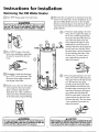
Instructions for Installation
Removing the Old Water Heater
O
Turn "OFF" the gas supply to the water heater.
Q
Disconnect the vent pipe from the draft hood where they
connect to the water heater. In most installations the vent
A WARNING
If the main gas line sh_gas
appliancesis used,l/
also shut %ff" the gas at eachappliance.Leaveall gasappli-|
ancesshut =off*untilthe waterheaterinstallationiscomplete. ]
devices are removed, Dispose of the draft hood, The new
water heater has the draft hood which must be used for
pipe canoperation.
be rifted off after any screw or other attached
proper
G
Q
Q
a. If you have copper piping to the water
four inches away from where they connect to the water heater. This will
be cut with a hacksaw approximately
avoid cutting off the pipes too short.
heater, the Disconnect
two copper the
water
pipes can
necessary.
temperaturepressure refiefvalve drain line. When
QTurn
Additional cuts can be made later if
the water heater is drained, disconnect
"OFF" the water to the water
heater. Some installations require that
the water be turned offto the entire
house.
_
the hose from the drain valve. Close
the drain valve. The water heater is
now completely disconnected and
(_
Check again to make sure the gas supply is "OFF" to the water heater. Then
ready to be removed.
I _
tal_
Q
with a pipe wrench at the union in each
from the gas control valve.
_)
Q
Attach a hose to the water heater drain
valve and put the other end in a floor
disconnect the gas supply connection
drain or outdoors. Open the water
heater drain valve. Open a nearby hot
water faucet which will relieve pressure
in the water heater and speed draining,
b. If you have galvanized pipe to the water
_,
_ _
fine. Also disconnect the piping
remaining tO the water heater. These
pieces should be saved since they may
be needed when reconnecting the new
heater, loosen the two galvanized pipes
water heater. Disconnect the temperature-pressure relief valve drain line.
When the water heater is drained, disconnect the hose from the drain valve.
Close the drain valve. The water heater
ready to be removed.
WARNING
The water passingout of the drainvalvemaybe extremelyhot.
To avoidbeing scalded,makesureall connections
are tight and
that thewaterflow isdirectedawayfrom anyperson,
A, CAUTION
Mineral buildupor sedimentmay haveaccumulatedin the old
water heater.Thiscausesthe water heaterto be muchheavier
9
thannormalandthis residue,if spilledout, couldcausestaining.
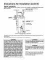
Instructions for Installation (cont'd)
Typical Installation
CHECKALL CONNECTIONS FOR LEAKS. CONSULTTHE LOCAL UTILITY COMPANY TO EXAMINE INSTALLATION FOR PROPRIETYAND SAFETY.
VACUUMRELIEF
REQUIRED
BY SOMECODES
_
(REFER
T
O
LOCAL
CODES)
HOTWATEROUTLET
gem
TOCHIMNEY _-_
TEMPERED _
_
_
COLDWATERINLET
_
W,TEROUT'ET
*MIXINGVALVE ]
GAS I
SUPPLY
--
TEMPERATURE-PRESSURE
RELIEF
VALVE
DISCHARGE
PIPE
R[_
_--
--
(Do notcapor plug)
V
DRA
__'_
_
_ DRAINVALVE
TOSUITABLE
DRAIN
This appliance has been design certified as complying with American National Standard/CSA Standard for water heaters and is considered suitable for.
Water (Potable) Heating: Al1 models are "considered suitable for water (potable) heating."
HOTTER WATER CAN
AWARNING
SCALD: Water
temperature
intended
to produce
which
will
hot
dish washing,
and other
and permanently injure
people are more likely to
heaters
This
. water heater shall
A WARNING
not be connected
are
water, Water
satisfy
clothes
heated
washing,
to a
sanitizing
needs
can scald
you upon contact. Some
be permanently injured by
to anyheat-
ing systems water
non-potable
or component(s)
heating appliance.
previously used with a
hot
water the
than
others.
These include the elderly,
children,
infirm,
or physically/mentally
hanclicapped. If anyone using hot water in your home fits
into one of these groups or if there is a local code or
state law requiring a certain temperature water at
the hot water tap, then you must take special precautions. In addition to using the lowest possible
temperature setting that satisfies your hot water
needs, a means such as a mixing valve, should be
used at the hot water taps used by these people or
at the water heater. Mixing valves are available at
plumbing supply or hardware stores. Follow manutacturers instructions for installation of the valves.
Before changing the factory setting on the thermostat, read the "Temperature Regulation" section in
this manual.
A WARNING
[I
Toxic chemicals such as used for treatment of boilers
or non-potable water heating appliances shall never J
be introduced into a potable water space heating
system.
NOTE: To protect against untimely corrosion of hot and
cold water fittings, it is strongly recommended that di-electric unions or couplings be installed on this water heater
when connected to copper pipe.
10
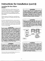
Instructions for Installation (cont'd)
Locating
Heater
the New Water
&WARNING
You should carefully choose an indoor location for the new
water heater, because the placement is a very important consideration for the safety of the occupants in the building and
for the most economical use of the appliance. This water
heater is not for use in manufactured (mobile) homes or out-
This water heater must not be installed directly on
carpeting. Carpeting must be protected by a metal
or wood panel beneath the appliance extending
beyond the full width and depth of the appliance
by at least 3 inches (76.2mm) in any direction, or if
the appliance is installed in an alcove or closet, the
entire floor must be covered by the panel. Failure to
doorinst_/lation,
Whether replacing an old water heater or putting the water
heater in a new location, the following critical points must be
observed.
heed this warning
_kWARNING
The location selected should be indoors as close as practical to
the gas vent or chimney to which the water heater vent is going
Minimum
clearances
between the water
heater and
combustible
and noncombustible
construction
are
1" at the sides and rear, 4" at the front, and 6" from
the vent pipe. Clearance from the top of the jacket I
is 18" on most models. Note that a lesser dimension I
may be allowed on some models. Refer to the label
to be connected, and as centralized with the water piping system
as possible. The water heater, as all water heaters, will eventually
leak. Do not install without adequate drainage provisions where
valveOn
theforWaterall
clearances.heater
adjacent
water flow wii1 cause damage,
_CAUTION
WATER HEATERS EVENTUALLY LEAK: Installation of
the water
heater must be accomplished in such a
12"MAX.
leak, the flow of water will not cause damage to
the structure. For this reason, it is not advisable to
manner that if the tank or any connections should
install
the
water
heater
in
an
attic
or
upper
may result in a fire hazard.
-
floor.
When such locations cannot be avoided, a suitable
drain pan should be installed
under the water
heater. Drain pans are available at your local hardware store. Such a drain pan must be not greater
than 1'½ inches deep, have a minimum length and
width of at least 2 inches greater than the water
to the gas contro
[E_II_I
I_III"N
VENTILATION
_
_.,
._w_F=_
I
OPENINGsAIR
O
I" HIN.
_
TOPVIEW
_
OF CLOSET
TOP VIEW I" MIN.
WITHOUTDOOR OFCLOSET
_'MAX.
WITHDOOR
_
OFDOOR
,
" MIN.
RECTANGU_R
3"
HIN
FRONT VIEVV
heater dimensions and must be piped to an adequate drain. The pan must not restrict combustion
air flow. Under no circumstances is the manufacturer or Maytag to be held liable for any water damage in connection with this water heater.
"I"MIN.
j
j
I Figure 1 I
AIRDUCT
AWARNING
AWARNING
A gas water heater cannot operate properly without the correct amount of air for combustion. Do
Propellants of aerosol sprays and volatile compounds, (cleaners, chlorine based chemicals, refrigerants, etc.) in addition to being highly flammable
in many cases, will also change to corrosive
not install in a confined area such a closet, unless
you provide air as shown in the "Locating The New
Water Heater" section. Never obstruct the flow of
ventilation air. If you have any doubts or questions
at all, call your gas company. Failure to provide the
proper amount of combustion air can result in a fire
or explosion and can cause DEATH, SERIOUS BODILY INJURY, OR PROPERTY DAMAGE.
hydrochloric acid when exposed to the combustion J
products of the water heater. The results can be
hazardous, and also cause product failure,
The location selection must provide adequate clearances for servicing and proper operation of the water heater.
11
Instructions for Installation (cont'd)
Locating the New Water
Heater (cont'd)
Combustion Air and Ventilation
for Appliances Located in
Unconfined Spaces
_, WARNING
Unconfined
Space is a space whose volume is not less than
If this water heater will be used in beauty shops,
barber shops, cleaning establishments, or self-service laundries
with dry cleaning
equipment,
it is
imperative
the water
heater and
or water
heaters
be installed that
so that
combustion
ventilation
air
50 cubic feet per 1,000 Bru per hour of the aggregate input
rating o£all appliancesinstalled in that space.Rooms cornmunicating directly with the space in which the appliances are
installed, through openings not furnished with doors, are
be taken from outside these areas. Refer to the
"Locating The New Water Heater" section of this
manual and also the latest edition of the National
Fuel Gas Code, ANSI Z223.1, also referred to as NFPA
54 for specifics provided concerning air required,
considered a part of the unconfined space
In unconfined spaces in buildings, infiltration maybe adequate to provide air for combustion, ventilation and dilution
AWARNING
of flue gases. However, in buildings of tight construction (for
example, weather stripping, heavily insulated, caulked, vapor
barrier, etc.), additional air may need to be provided using the
methods described in Combustion Air and Venfilation for
Ii
Appliances Located in Confined Spaces, b.
INSTALLATIONS IN AREAS WHERE FLAMMABLE LIQ-I
UIDS (VAPORS) ARE LIKELYTO BEPRESENTOR STOREDI
(GARAGES, STORAGE, AND UTILITY AREAS, ETC)"
Flammable liquids (such as gasoline, solvents, propane
(LP) or butane, etc.), all of which emit flammable I
vapors, may be improperly stored or used in such I
areas. The gas water heater pilot light or main burner
Combustion Air and Ventilation
A._
__ I_i
for mpp,,ances Located in
Confined Spaces
can ignite such vapors. The resulting flashback and fire I
can cause death or serious burns to anyone in thei
area, as well as property damage,
If installation in such areas is your only option, then I
the installation must be accomplished in a way that
Confined Spaceis a spacewhose volume is less than 50 cubic
feet per 1,000 Btu per hour of the aggregate input rating of all
appliances installed in that space.
a. ALL AIR FROM INSIDE BUILDINGS:
the pilot
main 18
burner
flame
are this
elevated
from
the flame
floor and
at least
inches.
While
may
reduce the chances of flammable vapors from a floor
spill being ignited, gasoline and other flammable substances should never be stored or used in the same
room or area containing a gas water heater or other
open flame or spark producing appliance,
NOTE: Flammable vapors may be drawn by air currents
from other areas of the structure to the appliance,
(See Page 11 Figure 1, and Figure 2 below)
The confined space shall be provided with two permanent
openings communicating directly with an additional
room(s) of sufficient volume so that the combined volume
of all spaces meets the criteria for an unconfined space.
The total input of all gas utilization equipment installed in
the combined space shall be considered in making this
determination. Each opening shall have a minimum free
area of one square inch per 1,000 BTU per hour of the
total input rating of all gas utilization equipment in the
confined space, but not less than 100 square inches. One
opening shall commence within 12 inches of the top and
one commencing within 12 inches of the bottom of the
enclosure.
ASVENT
IFigure
2]
12
Instructions for Installation (cont'd)
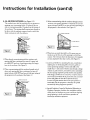
b. ALL AIR FROM OUTDOORS: (see Figures 3-5)
The confined space shall be provided with two permanent
openings, one commencing within 12 inches of the top
and one commencing within 12 inches from the bottom of
the enclosure. The openings shall communicate directly, or
by ducts, with the outdoors or spaces (crawl or attic) that
freely communicate with the outdoors.
3. When communicating with the outdoors through horizontal ducts, each opening shall have a minimum free area of 1
square inch per 2,000 BTU per hour of total input rating of
all equipment in the enclosure. (See Figure 5.)
[F,gu,
] 3
*LT._LET
A,_ w_._r,o_LOUVERS
4. When ducts are used, they shall be ofthe same cross-sectional area as the free area of the openings to which they
connect. The minimum short side dimension of rectangular
1. When directly communicating with the outdoors, each
opening shall have a minimum free area of 1 square inch
per 4,000 BTU per hour of total input rating of all equipment in the enclosure. (See Figure 3.)
air ducts shall not be less than 3 inches. (See Figure 5.)
5. Louvers and Grilles: In calculating free area, consideration
shall he given to the blocking effect of louvers, grilles or
screens protecting openings. Screens used shall not be
2. When communicating with the outdoors through vertical
ducts, each opening shall have a minimum free area of 1
square inch per 4,000 BTU per hour of total input rating of
all equipment in the enclosure. (See Figure 4.)
Figure
4
smaller than % inch mesh. If the free area through a design
of louver or grille is known, it should be used in calculating
the size opening required to provide the free area specified.
If the design and free area is not known, it may be assumed
that wood louvers will be 20-25 percent free area and metal
louvers and grilles will have 60-75 percent free area.
Louvers and grilles shall be fixed in the open position or
interlocked with the equipment so that they are opened
automatically during equipment operation.
6. Special Conditions Created by Mechanical Exhausting or
Fireplaces: Operation of exhaust fans, ventilation systems,
clothes dryers or fireplaces may create conditions requiring
]
]
special attention to avoid unsatisfactory operation of
installed gas utilization equipment.
13
Instructions for Installation (cont'd)
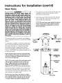
Water Piping
AWARNING
1. Look at the top cover of the water heater. The water outlet
is marked hot. Connect the hot water pipe to the hot
water outlet on the water heater.
HOTrER WATER CAN SCALD: Water heaters
are
intended to produce hot water. Water heated to a
temperature which will satisfy clothes washing, dish
washing,
and injure
other
permanently
are more likely to
water than others.
dren, the infirm,
sanitizing
needs can
scald
and
you
upon contact.
Some
people
be permanently injured by hot
These include the elderly, chilor physically/mentally
handi-
2. Look at the top cover of the water heater. The cold water
inlet is marked cold. Connect the cold water pipe to the
cold water inlet of the water heater.
capped. If anyone using hot water in your home fits
into one of these groups or if there is a local code or
state law requiring a certain temperature water at
the hot water tap, then you must take special precautions. In addition to usinc_the lowest possible
temperature
setting that satisfies your hot water
needs, a means such as a mixing valve, should be
used at the hot water taps used by these people or
at the water heater. Mixing valves are available at
_alumbing supply or hardware stores. Follow manucturers instructions for installation of the valves.
Before changing the factory setting on the thermostar, read the "Temperature Regulation" section in
this manual.
NOTE: This water heater is super insulated to minimize
heat loss from the tank. Further reduction in heat loss
can be accomplished by insulating the hot water lines
from the water heater.
THREADED
TO
SWEATCOUPLING
_
SHUTOFF
VALVE
hswtr
halo
ocedoa
tems or component(s)
used with a non-potable water heating
_
_
TO HOUSE
WATERLINE
If a water heater is installed in a closed water supply system;
such
as one having a back-flow preventer, check valve, water
appliance.
meter with a check valve, etc.., in the cold water supply;
means shall be provided to control thermal expansion.
Contact the local utility or call Maytag Customer Service
Center at 1-800-788-8899
for an authorized installer on how
to control this situation.
1_
I_
I I
HOTOUTLET
[_
S"_
_.._
]_
I
314"THREADED-COUPLING
1"ON 73 GAL.
COLD
--
NOTE: To protect against untimely corrosion of hot and
cold water fittings, it is strongly recommended that di-electric unions or couplings be installed on this water heater
when connected to copper pipe.
_
INLET
314"THREADED
COUPLING
1" ON 73 GAL.
_
TEMPERATUREPRESSURE
RELIEF
VALVE
*---
DISCHARGE
PIPE
NOTE: The secondary anode rod/hot oudet nipple and the
cold inlet nipple are packaged separately with the water
__
(Do not cap
heater. 73 gallon models have hot outlet and cold inlet
nipples only. The above parts must be installed in the
appropriate HOT and COLD water connection locations,
_
i_
f_l
or plug)
the water heater. The water heater is equipped with 3/4inch
water connections for 30, 40 and 50 gallon models and 1 inch
6" AIRGAP
water connections on 73 gallon models.
The illustration shows the attachment of the water piping to
NOTE: Ifusing copper tubing, solder tubing to an adapter
_
before attaching the adaptor to the cold water inlet connection.
Do not solder the cold water supply line direcdy to the cold
_
..
_]'l
I
FLOORDRAIN
-.,ater inlet. It will harm the dip tube and damage the tank.
14
Instructions for Installation (cont'd)
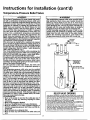
Temperature-Pressure Relief Valve
AWARNING
At the time of manufacture this water heater was provided with a combination temperature-pressuresrelief valve
certified by a nationally recognizedtesting laboratory that
maintains periodic inspection of production of listed
equipment or materials, as meeting the requirements for
Relief Valves and Automatic Gas Shutoff Devices for Hot
Water Supply Systems, and the latest edition of ANSI
Z21.22 and the code requirements of ASME. If replaced,
the valve must meet the requirements of local codes, but
not less than a combination temperature and pressure
relief valve certified as meeting the requirements for
Relief Valves and Automatic Gas Shutoff Devices for Hot
Water Supply Systems,ANSI Z21.22 by a nationally recognized testing laboratory that maintains periodic inspecton
I of productionof listed equipment or materials.
The valve must be marked with a maximum set pressure
AWARNING
The temperature-pressure relief valve must be manuall), operated at least once a year. Caution should be
taken to ensure that (1) no one is in front of or
around the outlet of the temperature-pressure relief
va ved scharge ne, and (2) the water manua y d sged will not cause any bodily injury or property
age because the water may be extremely hot.
Ier manually operating the valve, it fails to completely reset and continues to release water, immediately close the cold water inlet to the water heater,
follow the draining instructions, and replace the
temperature-pressure relief valve with a new one.
_
the water heater (150 Ibs./sq. in.) and a dischargecapacity
not lessthan the water heater input rate as shown on the
model rating plate. (Electric heaters - watts divided by
1000 x 3415 equal BTU/Hr.rate.)
Your local jurisdictional authority, while mandating the
not
marked hydrostaticworking
pressureof
use to
of exceedthe
a temperature-pressurerelief
valve complying
with
SHUTOFF
VALVE
HOT
_---_-'-_
ANSI
Z21.22
may
require
a valve
model different
from
the and
one ASME,
furnished
with
the water
heater.
Compliancewith suchlocalrequirements must be satisfied
by the installer or end user of the water heater with a
locally prescribed temperature-pressure relief valve
installed in the designatedopening in the water heater in
placeof the factoryfurnishedvalve.
For safe operation of the water heater, the relief valve
must not be removed from it's designated opening or
plugged.
The temperature-pressure relief valve must be installed
directly into the fitting of the water heater designated for
the relief valve. Positionthe valve downward and provide I
tubing sothat any dischargewill exit only within 6 inchesI
above, or at any distance below the structural floor. Be
certain that no contact is made with any live electrical
part. The discharge opening must not be blocked or'
reduced in size under any circumstances.Excessivelength,
over 30 feet, or use of more than four elbows can cause
restrictionand reducethe dischargecapacity of the valve.
No valve or other obstructionis to be placedbetween the
relief valve and the tank. Do not connect tubing directlyto
dischargedrain unlessa 6 air gap is provided. To prevent
bodily injury, hazard to life, or property damage, the relief
valve must be allowed to discharge water in quantities
should circumstancesdemand. If the dischargepipe is not
connected to a drain or other suitable means, the water
flow may causeproperty damage.
The DischargePipe:
• Must notbe smaller in size than the outlet pipe size of
the valve, or have any reducing couplings or other
restrictions.
. Must not be plugged or blocked,
• Must be of material listed for hot water distribution,
• Must be installed so as to allow complete drainage of
both the temperature-pressure relief valve, and the discharge pipe.
• Must terminate at an adequate drain,
• Must not have any valve between the relief valve and
tank.
COLD
f
__
_
_
--
PRESSURE
RELIEF
VALVE
_g)
[]
6"AIRGAP
--
B
m
FLOORDRAIN
RELIEF VALVE
OPENING
Atthetimeofmanufacture,
thiswater
heater
wasprovided
witha combination
temperature-pressure
relief
valve
listed
ascomplying
withthestandard
forrelief
valves
anda_oma_.ic
gasshut-off
devices
for hotwatersupp}y systems,
AnSI
z21.22.
Forsafe
operation
ofthewater
heater,
therelief
v
alve
m
ust
n
otbe
removed
fromitsdesignated
point
ofinstallation
orplugged.
Yourlocalurisdictional
authority,
whilemandating
theuseof a temperaturepressure
reliefvalve
complying
withAnsiZ21.22
andASME,
mayrequire
avalve
model
different
fromtheonefurnished
withthewater
heater.
Compliance
withsuchlocal
requirements
must
besatisfied
bytheinstaller
or
enduserofthewater
heater
witha locally
prescribed
temperature-pressure
reliefvalve
installed
inthedesignated
opening
inthewater
heater.
Seemanual
heading
-"Temperature-Pressure
Relief
Valves"
forinstallation
and
maintenance
ofrelief
valve,
discharge
line,andother
safety
precautions.
15
Instructions for Installation (cont'd)
Filling
the Water
Heater
A CAUTION
]
Never use this wa_less
it is completely [
filled with water. To prevent
damage to the tank, |
the tank must be filledwith water. Water must flow /
from the hot water faucet before turning "ON" gas/
tO the water heater.
I
For proper venting in certain installations, a larger diameter
vent pipe may be necessary. Due to great variances in instaUations, unforeseeable by the manufacturer of the water heater,
you must consult your gas company to aid you in determining
thethe
proper
yourNational
water heater
the vent
tables
in
latestventing
edition for
of the
Fuel from
Gas Code
ANSI
To fill the water heater with water:
Z223.1, also referred to as NFPA 54.
Close the water heater drain valve by turning the handle to
the right (clockwise). The drain valve is on the lower front
of the water heater,
Check the venting system for signs of obstruction or deterioration and replace if needed.
Open the cold water supply valve to the water heater.
NOTE: The cold water supply valve must he left open
when the water heater is in use.
The combustion and ventilation air flow must not be
obstructed.
To insure complete fiUing of the tank, allow air to exit by
opening the nearest hot water faucet. Allow water to run
]
_WARNING
Obstructed or deteriorated vent systems may preent a serious health risk or asphyxiation.
until a constant flow is obtained. This will let air out of the
water heater and the piping,
Check all new water piping for leaks. Repair as needed.
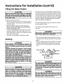
• Place the draft hood legs in the receiving holes on the top
Venting
of
the fit.
water heater. The legs will snap in the holes to give a
tight
• Place the vent pipe over the draft hood. With the vent pipe
in position, drill a sinai1 hole through both the vent pipe
AWARNING
VENT DAMPERS - Any vent damper, whether it is
operated thermally or otherwise must be removed
itits use inhibits proper drafting of the water
heater.
Thermally Operated Vent Dampers: Gas-fired water
heaters having thermal efficiency in excess of 80%
may produce a relatively low flue gas temperature.
Such temperatures
may not be high enough to
properly open thermally operated vent dampers.
This wouldcause
spillage of flue gases and may
cause carbon monoxide poisoning.
Vent dampers must bear evidence of certification as
complying with the latest edition of American
National Standard ANSI Z21.68 (ANSI Z21,66 & 87,
respectively, cover electrically and mechanically actuated vent dampers). Before installation of any vent
damper, consult your local gas utility or local codes
for further information.
and draft hood. Secure them together with a sheet metal
screw.
DRAFTHOOD
,
_
"_% _
_
] VENT_I
SCREW___I
_"_,_%l_'_
I
_lr
DRAFT
HOOD
_
LVENTTO OUTDOORSOR
DRAFT
-_UUu_ \_ CHIMNEY
(
oT_e
_
AWARNING
The water heater with draft hood installed must be
properly vented to a chimney which terminates outdoors. Never operate the water heater unless it is
vented to the outdoors and has adequate air supply
to avoid risks of improper operation, explosion or
asphyxiation.
AWARNING
To insure proper ventin_l of this gas-fired water
heater, the correct vent pipe diameter must be utiances
on aadditions
common orvent
with this
water
lized. Any
deletions
of other
gasheater
applimay adversely affect the operation of the water
heater, Consult the local gas utility or call Maytag
Customer Service at 1-800-788-8899 for an autho-
The vent pipe from the water heater must be no
less than the diameter of the draft hood outlet on
|the water heater, and must slope upward to the
rized servicer if any such changes are planned.
I chimney at least 1/,inch per linear foot.
AWARNING
16
1
Instructions for Installation
(cont'd)
Gas Piping
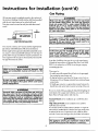
All vent gases must be completely vented to the outdoors of
AWARNING
the structure (dwelling). Install only the draft hood provided
with the new water heater and no other draft hood.
Vent pipes must be secured at each joint with sheet metal
screws,
Make sure the gas supplied is the same type listed
on the model rating plate. The inlet gas pressure
must not exceed 10.5 in, water column (2.6kPa) for
natural gas or 13 in. water column (3.2kPa) for
propane (L.R) gas. The minimum inlet gas pressure
listed on the model rating plate is for the purpose
--
"------_-
i
r
TO
of input adjustment.
CilMNEY
"WARNING
[
If thegas control valve is subjected to pressures
exceeding '/1 pound per square inch (3.5kPa), the I
damage to the gas control valve could result in a
f re or explos on from leak ng gas.
_
VENT PIPEINSTALLATION
There must be a minimum of 6" clearance between singlewall vent
AWARNING
pipe and any combustible material. Fill and seal any clearance
between single wallvent pipe and combustible materialwith mortar
If the
ances
ance.
water
mix, cement, or other noncombustible substance.For other than single wall, foliowvent pipe manufacturer'sclearance specifications.To
insure a tight fit of the vent pipe in a brick chimney, seal around the
vent pipe with mortar mix cement.
A gas line of sufficient size must be run to the water heater.
Consult the latest edition of National Fuel Gas Code ANSI
Z223.1, also referred to as NFPA 54 and the gas company
size.
concerning pipe
AWARNING
[
Failure to have required clearances between vent l
piping and combustible material will result in a fire ]
hazard.
I
AWARNING
main gas line shutoff serving all gas appli- [
is used, also turn "off" the gas at each appliLeave all gas appliances shut off until the
heater installation is complete.
There must be:
• A readily accessible manual shut offvalve in the gas supply
line serving the water heater, and
[
• A drip leg (sediment trap) ahead of the gas control valve to
help prevent dirt and foreign materials from entering the gas
control valve.
I
Be sure vent pipe is properly connected to prevent I
escape of danc_erous flue gases which could cause
deadly asphyxiation.
• A flexible gas connector or a ground joint union between the
shutoff valve and control valve to permit servicing of the unit.
_kWARNING
]
Chemical vapor corrosion of the flue and vent sys-/
tern may occur if air for combustion contains certain /
chemical vapors. Spray can propellants, cleaning sol-[
vents, refrigerator and air conditioner refrigerants, /
swimming
pool chemicals, calcium and sodium chlo-[
ride, waxes, bleach, and process chemicals are typi-|
Be sure to check all the gas piping for leaks before lighting the
water heater. Use a soapy water solution, not a match or open
cal compounds which are potentially corrosive.
sealevel
HighAltitude
Models are for installation from 3,300 to
5,500 feet above sea level.
flame. Rinse off soapy solution and wipe dry.
Standard Models are for installation up to 3,300 feet above
/
If a standard model is installed above 3,300 feet or a high altitude model is installed above 5,500 feet, the input rating must
be reduced at the rate of 4 percent for each 1,000 feet above
sea level. Contact your local gas utility for further information.
The appliance and AWARNING
its gas connection must be leak I
testedbefore
17
placing the appliance in operation.
Instructions for Installation (cont'd)
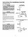
Gas Piping (cont'd)
A'WARNING
/
GAS PIPING
The appliance a_dual
shutoff valve[ _
must be disconnected from the gas supply piping"
system during any pressure testing of the gas system at test pressures in excess of 1/2 pound per
square inch (3.5kPa).
The appliance must be isolated from the gas supply piping system by closing its individual manual
shutoff valve during any pressure testing of the
gas supply piping system at test pressures equal
or less than 1/2 pound per square inch (3.SkPa).
WITH
FLEXIBLE CONNECTOR
GASSUPPLY
PIPING
_l
fill
MANUAL
SHUTOFF
VALVE
FLEXIBLE GAS CONNECTOR
•,WARNING
II
Use pipe joint compound or teflon tape marked as I
[ being resistant to the action of petroleum [Propane I
[ (L.R)]gases.
SEDIMENT
LABELED
ASCOMPLYING
WITH ANSI
STANDARDS
GROUNDJOINT
j
UNION(OPTIONAL)
TRAP
DRIP LEG
3" MIN.
A sediment trap shall be installed as close to the inlet of the
water heater as practical at the time of water heater installation. The sediment trap shall be either a tee fitting with a
capped nipple in the bottom outlet or other device recognized
as an effective sediment trap. If a tee fitting is used, it shall be
installed in conformance with one of the methods of installation shown below.
GAS PIPING
Connecting the gas piping to the gas control valve of the
water heater can be accomplished by either of the two methods shown.
GAS
(SEDIMENT
TRAP)CAP
CONTROL
VALVE
WITH ALL BLACK
GAS CONTROL
IRON
PIPE
TO
GASSUPPLY
PIPING
Q
[IContaminants in the_WARNING
gas lines may cause improper
Ioperation of the gas control valve that may result
lin fire or explosion. Before attaching the gas line
/be sure that all gas pipe is clean on the inside. To
trap any dirt or foreign material in the gas supply
line, a drip leg (sometimes called a sediment trap)
must be incorporated in the piping. The drip leg
must be readily accessible. Install in accordance
with the "Gas Piping" section. Refer to the latest
SHUToFFMANUAL
_ _
VALVE
GROUNDJOINT
UNION
_
I_
_-_ BLACK
PIIBLACK
PIPE_
also referred to as NFPA 54.
GAS
VALVE
edition of the National Fuel Gas Code, ANSI Z223.1,
T_I_I
"
18
DRIP LEG
_J CAP
_11
CONTROL
Instructions for Installation
Installation
BEFORE
LIGHTING
(cont'd)
Checklist
THE PILOT:
CHECK
• Check the gas fines for leaks.
FOR LEAKS
Be sure to check all your gas pipes for leaks before lighting
a. Use a soapy water solution. DO NOT test for gas leaks
using a match or open flame,
b. Brush the soapy water solution on all gas pipes, joints
and fittings,
c. Check for bubbling soap. This means you have a leak.
your water heater. Use a soapy water solution, not a match or
open flame. Check the factory gas fittings after pilot is lit and
gas control knob is still in "PILOT" position. Then, check the
fittings when the main burner is turned "ON". Use a soapy
water solution for this, too.
Turn "OFF" gas and make the necessary repairs.
d. Recheck for leaks.
e. Rinse offsoapy solution and wipe dry.
VENTPIPETO
OUTDOORS
ORCHIMNEY
SHUTOFF
VALVE
HO
• Is the new temperature-pressure relief valve properly
installed and piped to an adequate drain? See
"Temperature-Pressure Relief Valve" section.
OLD
• Are the cold and hot water lines connected to the water
heater correctly? See "Water Piping" instructions in the
"Instructions for Installation" section.
_.._H_[_iOOT
_
) co_i>tt_
GASSUPPLY
DRAFTHOOD
PRESSURE
RELIEF
VALVE
• Is the water heater completely fdled with water? See
"Filling" instructions in the "Instructions for Installation"
section.
SHUTOFF
VALVE
Will a water leak damage anything? See the "Locating the
New Water Heater" section.
Is there proper clearance between the water heater and
anything that might catch fire? See the "Locating the New
water Heater" section.
(Donot capor plug)
DRIPLEG----_ t
(Sedimenttrap) _ J_
PIPECAP
DRAINVALVE
6 iNCHAIRGAP
Do you have adequate ventilation so that the water heater
wifl operate properly? See "Combustion Air and Venti/ation"
in the "Instructions for Installation" section.
FLOOR
DRAIN
Is the draft hood vent piping properly secured? See
"Venting" instructions in the "Instructions for Installation"
section.
(POTABLE)
HEATING
Is there proper clearance between the vent pipe and anything that might catch on fire? See "Venting" instructions
in the "Instructions for Installation" section.
*_
ONLY
,_
ulXI#IR
_XlUU_ H'C_TAIr_C
Is the vent pipe properly sloped and does the vent terminate outdoors? See " Ventin g'i nstructions in the
"Instructions for Installation" section.
_, _,,
_ .........
_-A_R
GASFRES_JRE
_ wc
15o
_,
.
AUTOMATIC
STORAGE
WATER
HEATER
Do you need to call your gas company to check the gas
pipe and its hookup?
M.me' isaTrademarkofMayta
Corporation
and
]s used under L,eense to State _ndustrles, ]nc,
MODEL RATING PLATE
19
.e
Instructions for Operation
Lighting
_WARNING
__
BEFORE LIGHTING [PROPANE (L.P.) GAS WATER
HEATERS]: Propane (L.P.) gas is heavier than air.
Should there be a leak in the system, the gas will
settle near the ground. Basements, crawl spaces,
skirted areas under manufactured (mobile) homes
(even when ventilated), closets and areas below
ground level will serve as pockets for the accumulation of this gas. Before attempting to light or relight
the water heater's pilot or turning on a nearby electrical light switch, be absolutely sure there is no
accumulated gas in the area. Search for odor of gas
by sniffing at ground level in the vicinity of the
appliance. If odor is detected, follow steps indicated
at "For Your Safety" on the cover page of this manual then leave the premises.
[ Figure 6 1
Lighting and operating instructions are located on front of
the water heater, above or to one side of the gas control valve.
[Figure,
]
AWARNING
AN ODORANT IS ADDED TO THE GAS USED
FOR YOUR SAFETY
IF YOU SMELL GAS:
THIS
WATER
HEATER.
• Do not try to BY
light
any
appliance.
• Do not touch any electrical switch; do not use any
phone in your building.
• Immediately call your gas supplier from a neighbor's phone. Follow the gas supplier's instructions.
• If you cannot reach your gas supplier, call the fire
department.
_
[ Figure 8 ]
AWARNING
DO NOT force the gas control knob. Use only your
hand to push it down to light the pilot, or to turn it
to "ON", "OFF" or "PILOT". Never use a tool such as
a lever, wrench or pliers. Do not hit or damage the
knob. A damaged knob may result in an explosion
and serious injury. If you have problem turning the
knob, call the gas supplier immediately.
b
f
INNERDOOR
I
20
[ Figure 9 ]
_
OUTERDOOR
Instructions for Operation (cont'd)
Lighting
label on the water
heater
FOR YOUR SAFETY
as it appears
above the thermostat
READ BEFORE
LIGHTING
WARNING
If you do not follow these instructions exactly, a fire or explosion
may resu t caus ng propertydamage, personalinjury or lossof life.
A. Thisappliancehasa pilotwhichmustbe lightedby
• If youcannotreachyourgassupplier,
callthefire
hand.Whenlighting
thepilot,followtheseinstructions
department.
exactly.
C.Useonlyyourhandto pushin orturnthegascontrol
B.BEFORE
LIGHTING
smellallaroundtheappliance
area
knob.Neverusetools.Iftheknobwillnotpushin or
for gas.Besureto smellnextto thefloorbecause
turnbyhand.don'ttrytorepairit. callaqualified
earsomegasisheavier
thanairandwillsettleonthefloor,
vicetechnician.
Forceorattempted
repairmayresult
WHATTODOIFYOUSMELLGAS
ina fireor explosion.
a Donottrytolightanyappliance.
D.Donotusethisappliance
if anyparthasbeenunder
e Do nottouchanyelectricswitch;do notuseany
water.Immediately
calla qualified
servicetechnician
phoneinyourbuilding,
toinspect
theappliance
andto replace
anypartofthe
• Immediately
callyourgassupplierfroma neighbor's
controlsystemandanygascontrolwhichhasbeen
phone.Followthegassupplier's
instructions,
underwater.
LIGHTING
INSTRUCTIONS
1.STOP!Readthesafetyinformation
aboveonthislabel.
2.Remove
outerdoor.
3. Setthethermostatto lowestsettin_byturningthe
watertemperature
dialclockwise.
(f _.)to itslowest
temperature
setting(witharrowondial)asshown.DO
NOTFORCE,_
4. Turngascontrolknobclockwise_') to "OFF"position.Knobcannotbeturnedfrom"PILOT"to "OFF"
unlessknobis depressed
slightly.DO NOT FORCE.
(Figure6.page20)
5. Waitfive(5) minutes
to clearoutanygas.If youthen
smellgas.STOP!Follow"B" inthesafetyinformation
aboveonthislabel,if youdon'tsmellgas,gotothe
nextstep.
6. Remove(oropen)innerdoorlocatedbelowthegas
controlunit,
7, Findpilot-fellow
metaltubefromgascontrol.Thepilot
islocated
infrontoftheburner.
PILOT
BURNER I] THERMOCOUPLE
/'_ II
8. Ifyoudon'tsmellgas,turnknobongascontrolcounter
clockwise
(L_)_ to "PILOT"position.
(Figure7,page20)
9. Pushin controlknoball the wayand holddown.
Immediately
lightthepilotwitha match.Continueto
holdcontrolknobin foraboutone(1) minuteafter
thepilotis lit.Releaseknobanditwillpopbackup.
Pilotshouldremainlit. If it goesout,repeatsteps3
through8.
a If knobdoesnotpopupwhenroteased,
stopand
immediately
call yourservicetechnicianorgas
supplier.
• If the pilotwill notstay lit afterseveraltries,
depressandturnthegascontrolknobclockwise
O)
to "OFF"andcallyourservicetechnician
org-assupplier.
(Figure6.page20)
10.Replace
(orclose)innerdoor.(Figure9.page20)
11. Atarmslengthaway.turngascontrolknobcountert_
clockwise
to thefull
position.
Warning
66ON"
do not use gas control knob to regulate gas
flow.(Figure8,page20)
12.At armslengthaway,setthethermostat
to desired
setting.Themark( • ) indicativeof approximate
120°Fis preferredstartingpoint.Somelocallaws
mayrequirea lowerstartingpoint.If hotterwateris
desired,
seeinstruction
manual
and"warning"below.
13.Close
theouterdoor.
WARNING
Hotterwaterincreases
theriskof scaldinjury.Beforechangingtemperaturesettingseeinstructionmanual.
TO TURN
OFF GAS TO APPLIANCE
1. Setthe thermostatto lowestsettingbyturningthe
watertemperature
dialclockwise
(("_'_) to itslowest
temperature
setting(witharrowondial)asshown.DO
HOTFORCE,
21
2.Turngascontrolknobclockwise
_= ) to"OFF"position.Knobcannotbe turnedfrom"PILOT"to "OFF"
unlessknobisdepressed
slightly.
DONOTFORCE.
3. Closeouterdoor.
Instructionsfor Operation (cont'd)
Temperature
Regulation
Due to the nature of the typical gas water heater, the water
temperature in certain situations may vary up to 30°F higher or
lower at the point of use such as, bathtubs, showers, sink, etc.
Turn the water temperature dial clockwise (_"_)
to
decrease the temperature, or counterclockwise (f"-_)
to
increase the temperature.
This means that when the temperature adjustment dial is set
at the mark approximating 120° F, the actual water temperature at any hot water tap could be as high as 150°F or as low
as 90°E
J
Any water heater's intended purpose is to heat water. Hot
water is needed for cleaning (bodies, dishes, clothing). Hot
water will present a scald hazard. Depending on the time element, and the people involved (normal adults, children, tod-
_'-
½
dlers, elderly, infirm, etc.) scalding may occur at different
temperatures.
A WARNING
PILOT
HOTTER WATER CAN SCALD: Water heaters are
intended to produce hot water. Water heated to a
temperature which will satisfy clothes washing, dish
washing, and other sanitizing needs can scald and
permanently injure .you upon contact. Some people
are more likely to be permanently injured by hot
LIGHTING-
Set here before attempting to fight
pilot.
A-
Is a thermostat setting ofapproximately 120°F, which will supply hot
water at the most economical tern-
water than others. These include the elderly, children,
the infirm, or physically/mentally
handicapped. If
anyone us ng hot water in your home fits into one of
these 9roups or if there is a local code or state lawl
requiring a certain temperature water at the hot I
water tap, then you must take special precautions. In
addition to using the lowest possible temperature I
setting that satisfies your hot water needs, a means I
such as a mixing valve, should be used at the hot I
water taps usecl by these people or at the water l
heater. Mixing valves are available at plumbing supply or hardware stores. Follow manufacturers instructions for installation of the valves. Before changing
A- Is a thermostat setting ofapproximately 130°E
the factory setting on the thermostat,
read the
"Temperature Regulation" section in this manual.
C- Is a thermostat setting ofapproximately 15001:'.
AWARNING
peratures. The temperature
ment knob can be turned lower than
120°Fifdesired.
B- Is a thermostat setting ofapproximately 140°F.
I
VERYHOT-
I
Never allow small children to use a hot water tap,
or to draw their own bath water. Never leave a l
child or handicapped person unattended in a bathtub or shower.
adjust-
Is a thermostat setting of 1600E It is
recommended that the dial be set
lower whenever possible.
I
NOTE: Water temperature range of 120°F-140°F recommended by most dishwasher manufacturers.
The thermostat of this water heater has been factory set at its
lowest position, to reduce the risk of scald injury. It is
adjustable and must be reset to the desired temperature set-
AWARNING
ting. The mark (A) indicative of approximately 120°F is the
preferred starting point. Some states have a requirement for a
lower setting. If you need hotter water, follow directions for
temperature adjustment, but beware of the warnings in this
section.
Should overheating occur or the gas supply fail to shut off, I
turn "OFF" the manual gascontrolvalveto the appliance. ]
22
Service and Maintenance
Venting
System
Inspection
Burner
inspection
At least once a year a visual inspection should be made of the
A,WARNING
venting system.You should look for:
• Obstructions which could cause improper venting. The
combustion and ventilation air flow must not be obstructed,
Flood damage to a water heater may not be readily
visible or immediately
detectible.
However, over a
period of time a flooded water heater will create
dangerous conditions which can cause DEATH, SERIOUS BODILY INJURY, OR PROPERTY DAMAGE.
Contact the Maytag dealer from whom the appliance was purchased or call Maytag Customer Service
at 1-800-788-8899
for an authorized servicer to
replace a flooded water heater. Do not attempt to
repair the unit! It must be replaced!
• Damage or deterioration which could cause improper venting or leakageof combustion products,
• Rusted flakes around top of water heater,
At least once a year a visual inspection should be made of the
main burner and pilot burner. The drawing is for your reference.
_, WARNING
Chemical vapor corrosion of the flue and vent system may occur if air for combustion contains certain
chemical vapors. Spray can propellants, cleaning solvents, refrigerator and air conditioner refrigerants,
swimming pool chemicals, calcium and sodium chloride, waxes, bleach, and process chemicals are typi-
You should check for sooting which is not normal and will
impair proper combustion.
cal compounds which are potentially corrosive.
Obstructed or deteriorated
vent systems may pre-
sent a serious health r sk or asphyxiat on.
Be sure the vent piping
is properly
I could cause deadly _WARNING
asphyxiation.
_...._.
4
)
NATURALORPROPANE
(L.R)GASBURNER
connected to I
]J
OR
_,WARNING
If
after inspection
the vent flue
system
you which
found [
prevent
escape of of
dangerous
gasses
sooting or deterioration, something is wrong. Call
the local gas utility or Maytag Customer Service at
1-800-788-8899 for an authorized servicer to correct
the problem and clean or replace the flue and venting before resuming operation of the water heater.
Failure to make corrections can result in a fire, or
explosion causing DEATH, SERIOUS BODILY INJURY,
OR PROPERTY DAMAGE.
_
NATURALORPROPANE
IL.P.)GASBURNER
_,WARNING
Soot build-up indicates a problem that requires correction before further use. Turn "OFF" gas to water
heater and leave "OFF" until repairs are made,
because failure to correct the cause of the sooting
can result in a fire or explosion causing DEATH,
SERIOUS BODILY INJURY, OR PROPERTY DAMAGE.
23
Service and Maintenance (cont'd)
L.P.Gas Control Valve & Burner
Assembly Replacement
Information
Burner Cleaning
In the event your burner needs cleaning, use the following
_WARNING
instructions:
PROPANE (L.P.) GAS CONTROL VALVE AN BURNER
ASSEMBLY REPLACEMENT INFORMATION.
]f inspection of the burner shows that cleaning is required,
For Propane (L.R) Gas Models Only:
turn the gas control knob clockwise (_'_)
Your water heater is equipped with a Propane (L.R)
gas control valve and a main burner assembly with
left hand threads for the following fittings and their
connections.
position, depressing slightly.
to the "OFF"
NOTE: The knob carlnot be Uurnedfrom "PILOT"
"OFF" unless knob is depressed slightly. DO NOT
FORCE.
• The connection between the manifold and the gas control
valve (A to B) are left hand threads.
to
Loose deposits on or around the burner can be removed by
carefiflly using the hose of a vacuum cleaner inserted through
• The connection between the main burner orifice and the mani-
the access door of the water heater. If the burner needs to be
fold (C to D) are left hand threads,
removed for additional cleaning, call Maytag Customer
Service at 1-800-788-8899 for an authorized servicer to
For ordering these replacement parts, please refer to the "Repair
Parts List" section of this manual,
remove and clean the burner and correct the problem that
required the burner to be cleaned.
The water heater should be drained if being shut down during
freezing temperatures. Also periodic draining and cleaning of
sediment from the tank may be necessary.
Draining
A_
_I
• CLOSE the cold water inlet valve to the water heater.
" Turn the gas control knob to the "OFF" position.
• OPEN a nearby hot water faucet and leave open to allow
for draining.
• Connect a hose to the drain valve and terminate to an ade-
B
quate drain.
• OPEN the water heater drain valve to allow for tank
draining.
NOTE: If the water heater is going to be shut down and
drained for an extended period, the drain valve should be
left open with hose connected allowing water to terminate
to an adequate drain.
• Close the drain valve.
• Follow instructions in the "Filling The Water Heater"
section.
• Follow the lighting instructions in the "Lighting" section to
restart the water heater.
24
Service and Maintenance (cont'd)
Temperature-Pressure
Valve Operation
The temperature-pressure
ated at least once a year.
Relief
Drain Valve Washer
Replacement
relief valve must be manually oper-
NOTE: For replacement, use a 1½z"x _'_" x _/s"thick washer
awil_hle at your nearest hardware store. For ordering
replacement washers, refer to the "Repair Parts List" section.
2. Follow "Draining" instructions.
3. Turning counter clockwise, remove the hex cap below the
screw handle.
4. Remove the washer and put the new one in place.
1. Turn "OFF _gas supply to water heater.
5. Screw the handle and cap assembly back into the drain
valve and retighten using a wrench. DO NOT OVER
TIGHTEN.
DISCHARGE PIPE
Failure to install and maintain a new properly listed temperature-pressure relief valve will release the manufacturer from
any claim which might result from excessive temperature or
6. FoUow instructions in the "Filling The Water Heater"
section.
7. Check for leaks.
pressure.
8. Follow the lighting instructions in the "Instructions for
Operation" section to restart the water heater.
If the temperature-pressure
_,WARNING relief valve on the
appliance
weeps
or discharges
periodically,
this
may
be due
to thermal
expansion.
Your water
heater may have a check valve installed in the
water line or a water meter with a check valve. Call
HANDLEAND
_
__
_:::_
CAPASSEMBLY
WASHER
Mayta_ Customer Service at 1-800-788-8899 for an
authorized servicer for further information. Do not
plug the temperature-pressure relief valve.
Housekeeping
AWARNING
When checking the temperature-pressure
relief
valve operation, make sure that (1) no one is in
front of or around the outlet of the temperaturepressure relief valve discharge line, and (2)that the
water
manually
discharged
will not cause any
property
damage because the water may be
extremely hot.
Vacuum around base of water heater for dust, dirt, and lint on
aregular basis.
Combustible materials such as clothing, cleaning materials, or
If after manually operating the valve, it fails to
completely reset and continues to release water,
immediately close the cold water inlet to the water
heater, follow the draining
instructions,
and
replace the temperature-pressure
relief valve with
a new one.
proper clearancesfrom the water heater must be maintained
flammable liquids, etc. must not be placed against or adjacent
to the water heater.
To insure sufficient ventilation and combustion air supply,
at all times.
Service
Before calling for repair service, read the Start Up Conditions
and Operational Conditions found in the Troubleshooting
Guide of this manual.
If a condition persists or you are uncertain about the operation of the water heater, let a qualified person check it out.
Call Maytag Customer Service at 1-800-788-8899
authorized servicer.
25
for an
Troubleshooting
Start Up Conditions
CONDENSATION
THERMAL
Whenever the water heater is filled with cold water, a certain
amount of condensation will form while the burner is on. A
water heater may appear to be leaking when in fact the water
is condensation. This usually happens when:
Water supply systems may, because of high line pressure, frequent cut-offs, the effects of water hammer and others, have
installed devices such as pressure reducing valves, check
valves, back flow preventers, etc. to control these types of
" When a new water heater is filled with cold water for
the first time.
problems. When these devices are not equipped with an internal by-pass, and no other measures are taken, the devices
cause the water system to be closed. As water is heated, it
• When gas burns and water vapor is produced in water
heaters, particularly high efficiency models where flue
expands (thermal expansion) and closed systems do not allow
for the expansion of heated water.
temperatures are lower.
EXPANSION
The water within the water heater tank expands as it is heated
and increases the pressure of the water system. If the relieving
• When you use large amounts of hot water in a short
time and the refill water is very cold.
point of the water heater's temperature-pressure relief valve is
reached, the valve will relieve the excess pressure. The ternperature-pressure relief valve is not intended for the constant rellefofthermal expansion. This is an unacceptable
condition and must be corrected.
Moisture from the products of combustion condense on the
cooler tank surfaces and form drops of water which may fall
onto the burner or other hot surfaces to produce a "sizzling" or
"frying" noise.
It is recommended that any devices installed which could create
Excessive condensation can cause pilot outage due to water
running down the flue tube onto the main burner and putting
out the pilot,
a closed system have a by-pass and/or the system have an
expansion tank to reheve the pressure built by thermal expansion in the water system. Expansion tanks are available for
ordering through Maytag Customer Service (1-800-788-8899).
Contact the local plumbing inspector, water supplier, and/or
call Maytag Customer Service at 1-800-788-8899 for an
authorized servicer for assistance in controlling these situations.
Because of the suddenness and amount of water, condensation
water may be diagnosed as a "tank leak". After the water in
the tank warms up (about 1-2 hours), the condition should
disappear.
\
Do not assume the water heater is leaking until there has been
enough time for the water in the tank to warm up.
STRANGE
An undersized water heater will cause more condensation.
The water heater must be sized properly to meet the family's
demands for hot water including dishwashers, washing
machines and shower heads.
SOUNDS
Possible noises due to expansion and contraction of some
metal parts during periods of heat-up and cool-down do not
represent harmful or dangerous conditions.
Condensation
Excessive condensation may be noticed during the winter and
early spring months when incoming water temperatures are at
their lowest.
causes sizzling and popping with the burner
area during heating and cooling periods and should be considered normal. See "Condensation" section.
Good venting is essential for a gas fired water heater to operate properly as well as to carry away products of combustion
and water vapor.
SMOKE/ODOR
It is not uncommon to experience a small amount of smoke
and odor during the initial start-up. This is due to burning off
ofoil from metal parts, and will disappear in a short while.
26
Troubleshooting
Operational
SMELLY
(cont'd)
Conditions
WATER
HIGH
TEMPERATURE
SHUT
OFF SYSTEM
In each glasslined water heater there is installed at least one
This water heater is equipped with an automatic gas shut off
anode rod (see parts section) for corrosion protection of the
tank. Certain water conditions will cause a reaction between
this rod and the water. The most common complaint associated with the anode rod is one of a "rotten egg smell". This
odor is derived from hydrogen sulfide gas dissolved in the
water. The smell is the result of four factors which must all be
present for the odor to develop:
system. The high temperature shut offis built into the gas
control valve. This system shuts offthe gas supply to the
water heater burners when high water temperatures are present. It is non-resetrable. If the high temperature shut off
activates, the gas control valve must be replaced. If this were
to occur, turn "OFF" the entire gas supply to the water heater.
Call Maytag Customer Service at 1-800-788-8899 for an
authorized servicer.
a. a concentration of sulfate in the supply water.
b. little or no dissolved oxygen in the water.
c. a sulfate reducing bacteria within the water heater.
(This harmless bacteria is non-toxic to humans.)
'[
AWARNING
]1
1
I Should overheating occur or the gas supply fail to [
Ishut off, turn "OFF" the manual gas control valve tol
[the appliance.
d. an excess of active hydrogen in the tank. This is caused
by the corrosion protective action of the anode.
NOT ENOUGH
Smelly water may be efiminated or reduced in some water
heater models by replacing the anode(s) with one of less active
material, and then chlorinating the water heater tank and all
]
OR NO HOT WATER
1. Check the manual gas shut offvalve to be sure it is open.
hot water lines. Call Maytag Customer Service at 1-800-7888899 for an authorized servicer for further information concerning an Anode Replacement Kit #66001068 and this
Chlorination Treatment.
2. Check the pilot flame. It may have gone out. All models
have an opening behind the outer door for viewing the pilot.
3. If the pilot is not lit, follow the "Lighting" instructions in this
manual or located above the gas control valve on the water
If the smelly water persists after the anode replacement and
chlorination treatment, we can only suggest that continuous
chlorination and filtering conditioning equipment be considered to eliminate the water problem,
heater to relight the pilot. If the water was extremely hot and
is now cold, the high limit safety temperature shut offmay
have put out the burner and pilot. If the high temperature
shut offacfivates, the gas control valve must be replaced. Call
Maytag Customer Service at 1-800-788-8899 for an autho-
Do not remove the anode leaving the tank unprotected. By
doing so, all warranty on the water heater tank is voided.
rized servicer.
4. The gas control knob must be turned to the "ON" position.
"AIR"
IN HOT WATER
FAUCETS
5. The temperature adjustment dial may be set too low. See the
"Temperature Regulation" section.
A WARNING
6. The gas company can check the gas input to see flit is correct.
HYDROGEN GAS: Hydrogen gas can be produced in
a hot water system that has not been used for a
long period of time (generally two weeks or more).
Hydrogen gas is extremely flammable and explosive. TO prevent the possibility of injury under these
conditions, we recommend the hot water faucet be
opened for several minutes at the kitchen sink
before any electrical appliances which are connected to the hot water system are used (such as a dishwasher or washing machine). If hydrogen gas is present, there will probably be an unusual sound similar to air escaping through the pipe as the hot
water faucet is opened. There must be no smoking
or open flame near the faucet at the time it is open.
An underflred water heater will not heat water as quickly
7. Look for leaking or open hot water faucets. Make sure all are
closed.
8. The cold water inlet temperature may be cuider during the
winter months. It will take longer to heat the water and
seem like less hot water.
9. If you cannot find what is wrong, call Maytag Customer
Service (1-800-788-8899 for an authorized servicer.
27
Troubleshooting (cont'd)
Operational
Conditions (cont'd)
WATER IS TOO HOT
1. The temperature adjustment dlal may be set too high. See the
"Temperature Adjustment" section.
NOTE: A period of time is necessary after an adjustment
has been made for the water temperature to reach the new
temperature setting.
2. If lower temperature settings will not lower the water temperature, call Maytag Customer Service (1-800-788-8899) for an
authorized servicer.
_WARNING
Due to the nature of the typical gas water heater,
the water temperature in certain situations may be
hotter than the thermostat setting.
Short, frequent draws of hot water - especially with
very coldincoming water - can shock the thermostat into brief operation resulting in hotter and hotter layers of water closer to the top of the tank.
Changes in hot water usage patterns or raisinc_the
temperature differential between the cut-on ot the
thermostat and the cold water temperature
will
usually eliminate the problem.
28
Troubleshooting (cont'd)
Leakage
Checkpoints
Use this guide to check a "Leaking" water heater. Many sus-
A CAUTION
pected "Leakers" are not leaking tanks. Often the source of
the water can be found and corrected,
Read this manual first. Then before checkingthe
water heater make sure the gas supply hasbeen
turned "OFF", and never turn the gas "ON" before
the tank is completely full of water.
If you are not thoroughly familiar with your local gas codes
your water heater, and safety practices, contact your local gas
A CAUTION
Never use this water heater unless it is completely [
filled with water, Toprevent damage to the tank, I
the tank must be filledwith water, Water must flow
utility or call Maytag Customer Service at 1-800-788-8899
for an authorized servicer to check the water heater.
from
to
thethe
water
hot heater,
water faucet before turning "ON" gas
densed out of the combustion products. This is caused
by a problem in the vent. Call Maytag Customer Service
at 1-800-788-8899 for an authorized servicer.
be
in humid weather
*Condensafion may
seen on pipes
or pipe connections may be leaking.
O
O'The
O
O
primary anode rod fitting may be leaking.
Water at the draft hood is water vapor which has conSmall amounts of water from temperature-pressure relief
valve may be due to thermal expansion or high water
pressure in your area.
The
O*
temperature-pressure
the tank fitting.
relief valve may be leaking at
Water from a drain valve may be due to the valve opened
sfighfly.
_*The
drain valve may be leaking at the tank fitting.
O
Combustion products contain water vapor which can
condense on the cooler surfaces of the tank. Droplets
form and drip into the fire or run on the floor. This is
common at the time ofstartup after installation and
when incoming water is cold.
O
Water in the water heater bottom or on the floor may be
from condensation, loose connections, or the relief valve.
DO NOT replace the water heater until a full inspection
of all possible water sources is made and necessary corrective steps taken. Leakage from other appliances, water
lines, or ground seepage should also be checked.
*NOTE: To check where threaded portion enters tank,
insert cotton swab between jacket opening and fitting. If
cotton is wet, follow "Draining" instructions in the
"Service and Maintenance" section and then remove fit-
/
_'
ring. Put pipe dope or teflon tape on the threads and
replace. Then follow "Filling the Water Heater" instructions in the "Instructions for Installation" section.
29
Repair Parts List
MAYTAG GAS WATER HEATERS
MODEL NUMBERS:
HN4930T
30 Gallon Natural Gas
HN5930T
30 Gallon Natural Gas
HP4930T
30 Gallon Propane (L.R) Gas
HP5930T
30 Gallon Propane (L.R) Gas
HN4940S
40 Gallon Natural Gas
HN5940S
40 Gallon Natural Gas
18
5
16
'15
3
3O
Repair Parts List (cont'd)
MAYTAG GAS WATER HEATERS
MODEL NUMBERS:
HN4930T
30 Gallon Natural Gas
HN5930T
30 Gallon Natural Gas
HP4930T
30 Gallon Propane (L.R) Gas
HP5930T
30 Gallon Propane (L.R) Gas
HN4940S
40 Gallon Natural Gas
HN5940S
40 Gallon Natural Gas
MODEL NUMBERS
KEY
NO.
1
2
3
4
HN4930T
HN5930T
PART DESCRIPTION
HP4930T
HP5930T
HN4940S
HN5940S
PART NUMBERS
Temperature-Pressure Relief Valve
Primary Anode Rod
Drain Valve
Drain Valve Washer
66001079
66001020
66001016
66001079
66001020
66001016
66001079
66001020
66001016
66001079
66001020
66001016
66001079
66001020
66001016
66001079
66001020
66001016
(_½2'_
x _Y_"x W_thick) *
66001021
66001021
66001021
66001021
66001021
66001021
5
6
Secondary Anode Rod
Pilot (Natural)
66001217
66001023
66001217
66001023
66001217
--
66001217
--
66001217
66001023
66001217
66001023
6
7
Pilot (Propane [L.R])
Thermocouple
-66001017
-66001017
66001193
66001017
66001193
66001017
-66001017
-66001017
8
9
Pilot Tubing w/Fittings (19" long)
Burner Orifice
66001024
66001025
66001024
66001035
66001024
66001172
66001024
66001041
66001024
66001025
66001024
66001035
10
11
12
13
Drill Size
Manifold
Burner
Outer Door
Inner Door
(#33)
66001322
66001027
66001190
66001029
(#36)
66001322
66001027
66001190
66001029
(#50)
66001323
66001027
66001190
66001029
(#51)
66001323
66001027
66001190
66001029
(#33)
66001326
66001027
66001190
66001029
(#36)
66001326
66001027
66001190
66001029
14
Gas Control Valve (Natural)
66001076
66001076
--
--
66001076
66001076
14
15
16
17
Gas Control Valve (Propane [L.P.])
Dip Tube
Flue Baffle
Draft Hood
-66001030
66001286
66001032
-66001030
66001286
66001032
66001078
66001030
66001212
66001032
66001078
66001030
66001212
66001032
-66001263
66001333
66001032
-66001263
66001333
66001032
18
#
Nipple (Cold Inlet)
Manual
66001112
66001112
66001112
66001112
66001149
66001112
66001112
Also available at most hardware stores,
Now that you have purchased this Gas Water Heater, should a
need ever exist for repair parts or service, simply call Maytag
Customer Service at 1-800-788-8899 for an authorized servicer.
The model number of this Gas Water Heater will be found
on the model rating plate located near the gas control valve.
Be sure to provide pertinent facts when you call.
When ordering repair parts, always give the following
information:
Modal Number
Serial Number
Part Description
Part Number
THIS IS A REPAIR PARTS LIST, NOT A PACKING
LIST.
31
Repair Parts List (cont'd)
MAYTAG GAS WATER HEATERS
MODEL NUMBERS:
HP4940S
HP5940S
HN4940T
HN5940T
HP4940T
HP5940T
40
40
40
40
40
40
Gallon
Gallon
Gallon
Gallon
Gallon
Gallon
Propane (L.R) Gas
Propane (L.P.) Gas
Natural Gas
Natural Gas
Propane (L.R) Gas
Propane (L.P.) Gas
18
5
16 _
_
2
32
'15
Repair Parts List (cont'd)
MAYTAG GAS WATER HEATERS
MODEL NUMBERS:
HP4940S
HP5940S
HN4940T
HN5940T
HP4940T
HP5940T
40
40
40
40
40
40
Gallon
Gallon
Gallon
Gallon
Gallon
Gallon
Propane (L.P.) Gas
Propane (L.P.) Gas
Natural Gas
Natural Gas
Propane (L.P.) Gas
Propane (L.R) Gas
MODEL NUMBERS
KEY
NO.
1
2
3
4
HP4940S
HP5940S
PART DESCRIPTION
HN4940T
HN5940T
PART NUMBERS
HP4940T
HP5940T
Temperature-Pressure Relief Valve
Primary Anode Rod
Drain Valve
Drain Valve Washer
66001079
66001020
66001016
66001079
66001020
66001016
66001079
66001020
66001016
66001079
66001020
66001016
66001079
66001020
66001016
66001079
66001020
66001016
('½{'x'¥_"x
¼"thick)*
66001021
66001021
66001021
66001021
66001021
66001021
5
6
6
7
8
9
Secondary Anode Rod
Pilot (Natural)
Pilot (Propane [L.P.])
Thermocouple
Pilot Tubing w/Fittings (19" long)
Burner Orifice
66001217
-66001193
66001017
66001024
66001172
66001217
-66001193
66001017
66001024
66001041
66001217
66001023
-66001017
66001024
66001025
66001217
66001023
-66001017
66001024
66001035
66001217
-66001193
66001017
66001024
66001172
66001217
-66001193
66001017
66001024
66001041
10
11
12
13
Drill Size
Manifold
Burner
Outer Door
Inner Door
(#50)
66001327
66001027
66001190
66001029
(#51)
66001327
66001027
66001190
66001029
(#33)
66001324
66001027
66001190
66001029
(#36)
66001324
66001027
66001190
66001029
(#50)
66001325
66001027
66001190
66001029
(#51)
66001325
66001027
66001190
66001029
14
14
15
16
17
Gas Control Valve (Natural)
Gas Control Valve (Propane [L.P.])
Dip Tube
Flue Baffle
Draft Hood
-66001078
66001263
66001333
66001032
-66001078
66001263
66001333
66001032
66001076
-66001030
66001310
66001032
66001076
-66001030
66001310
66001032
-66001078
66001263
66001203
66001032
-66001078
66001263
66001203
66001032
18
#
Nipple (Cold Inlet)
Manual
66001112
66001112
66001112
66001112
66001149
66001112
66001112
Also available at most hardware stores.
Now that you have purchased this Gas Water Heater, should a
need ever exist for repair parts or service, simply call Maytag
Customer Service at 1-800-788-8899 for an authorized servicer.
The model number of this Gas Water Heater will be found
on the model rating plate located near the gas control valve.
Be sure to provide pertinent facts when you call.
When ordering repair parts, always give the following
information:
THIS IS A REPAIR PARTS LIST, NOT A PACKING
Model
Number
Serial Number
LIST.
Part Description
Part Number
33
Repair Parts List (cont'd)
MAYTAG GAS WATER HEATERS
MODEL NUMBERS:
HN4950S
HN5950S
HP4950S
HP5950S
HN4950T
HN5950T
50
50
50
50
50
50
Gallon
Gallon
Gallon
Gallon
Gallon
Gallon
Natural Gas
Natural Gas
Propane (L.R) Gas
Propane (L.R) Gas
Natural Gas
Natural Gas
;18
5
16
P15
3
4_p
'_
12 [_
_
_e
_=_
1_
1
11
9g
,o
7
34
Repair Parts List (cont'd)
MAYTAG GAS WATER HEATERS
MODEL NUMBERS:
HN49505
50 Gallon Natural Gas
HN5950S
50 Gallon Natural Gas
HP49505
50 Gallon Propane (L.R) Gas
HP59505
50 Gallon Propane (L.R) Gas
HN4950T
50 Gallon Natural Gas
HN5950T
50 Gallon Natural Gas
KEY
NO.
HN59505
66001010
66001010
66001010
66001010
66001079
66001079
PART DESCRIPTION
Relief Valve
MODEL NUMBERS
HP49505
HP59505
PART NUMBERS
HN49505
HN49SOT
HN5950T
1
Temperature-Pressure
2
3
4
Primary Anode Rod
Drain Valve
Drain Valve Washer
66001251
66001015
66001251
66001015
66001251
66001015
66001251
66001015
66001020
66001016
66001020
66001016
(1½2"x 13/6,"x¼"thick)*
66001021
66001021
66001021
66001021
66001021
66001021
5
6
6
7
Secondary Anode Rod
Pilot (Natural)
Pilot (Propane [L.P.])
Thermocouple
66001217
66001023
-66001017
66001217
66001023
-66001017
66001217
-66001193
66001017
66001217
-66001193
66001017
66001217
66001023
-66001017
66001217
66001023
-66001017
8
9
Pilot Tubin 9 w/Fittings (19"long)
Burner Orifice
66001024
66001025
66001024
66001035
66001024
66001172
66001024
66001041
66001024
66001025
66001024
66001035
10
11
Drill Size
Manifold
Burner
(#33)
66001329
66001027
(#36)
66001329
66001027
(#50)
66001284
66001027
(#51)
66001284
66001027
(#33)
66001326
66001027
(#36)
66001326
66001027
12
13
Outer Door
Inner Door
66001190
66001029
66001190
66001029
66001190
66001029
66001190
66001029
66001190
66001029
66001190
66001029
14
Gas Control Valve (Natural)
66001003
66001003
--
--
66001076
66001076
14
15
16
17
Gas Control Valve (Propane [L.P.])
Dip Tube
Flue Baffle
Draft Hood
-66001263
66001287
66001032
-66001263
66001287
66001032
66001004
66001263
66001287
66001032
66001004
66001263
66001287
66001032
-66001030
66001288
66001032
-66001030
66001288
66001032
18
#
Nipple (Cold inlet)
Manual
66001112
66001112
66001112 I 66001112
66001149
66001112
66001112
Also available at most hardware stores.
Now that you have purchased this Gas Water Heater, should a
need ever exist for repair parts or service, simply call Maytag
Customer Service at 1-800-788-8899 for an authorized servicer.
The model number of this Gas Water Heater will be found
on the model rating plate located near the gas control valve.
Be sure to provide pertinent facts when you call.
When ordering repair parts, always give the following
information:
THIS IS A REPAIR PARTS LIST, NOT A PACKING
Model Number
Serial Number
Part Descripdon
Part Number
LIST.
35
Repair Parts List (cont'd)
MAYTAG GAS WATER HEATERS
MODEL NUMBERS:
HP4950T
HP5950T
HN4975S
HN5975S
HP4975S
HP5975S
50
50
73
73
73
73
Gallon
Gallon
Gallon
Gallon
Gallon
Gallon
Propane (L.P.) Gas
Propane (L.P.) Gas
Natural Gas
Natural Gas
Propane (L.R) Gas
Propane (L.R) Gas
17_
118
5
16
I15
3
4_I;_
12 _
_
0
1_
i
11
9g
10
7
36
Repair Parts List (cont'd)
MAYTAG GAS WATER HEATERS
MODEL NUMBERS:
HP4950T
HP5950T
HN4975S
HN5975S
HP4975S
HP5975S
50
50
73
73
73
73
Gallon
Gallon
Gallon
Gallon
Gallon
Gallon
Propane (L.R)
Propane (L.R)
Natural Gas
Natural Gas
Propane (L.R)
Propane (LP.)
Gas
Gas
Gas
Gas
MODEL NUMBERS
KEY
NO.
1
2
3
4
HP4950T
HP5950T
PART DESCRIPTION
HN4975S
HN5975S
HP4975S
HP5975S
PART NUMBERS
Temperature-Pressure Relief Valve
Primary Anode Rod
Drain Valve
Drain Valve Washer
66001079
66001020
66001010
66001079
66001020
66001010
66001079
66001020
66001010
66001079
66001020
66001010
66001079
66001020
66001010
66001079
66001020
66001010
(_TA2"x_Y_"x %"thick)*
66001021
66001021
66001021
66001021
66001021
66001021
5
6
SecondaryAnodeRod**
Pilot (Natural)
66001217
--
66001217
--
66001148
66001192
66001148
66001192
66001148
--
66001148
--
6
7
Pilot (Propane [L.P.])
Thermocouple
66001193
66001017
66001193
66001017
-66001017
-66001017
66001194
66001017
66001194
66001017
8
9
Pilot Tubing w/Fittings (19"long)
Burner Orifice
66001024
66001172
66001024
66001041
66001024
66001169
66001024
66001168
66001024
66001175
66001024
66001048
10
11
12
13
Drill Size
Manifold
Burner
Outer Door
Inner Door
(#50)
66001327
66001027
66001190
66001029
(#51)
66001327
66001027
66001190
66001029
(#23)
66001362
66001359
66001190
66001029
(#27)
66001362
66001359
66001190
66001029
(#45)
66001364
66001363
66001190
66001029
(#47)
66001364
66001363
66001190
66001029
14
14
Gas Control Valve (Natural)
Gas Control Valve (Propane [L.P.])
-66001078
-66001078
66001077
--
66001077
--
-66001078
-66001078
15
16
17
Dip Tube
Dip Tube Adaptor
Flue Baffle
Draft Hood
66001030
-66001203
66001032
66001030
-66001203
66001032
66001263
66001271
66001336
66001051
66001263
66001271
66001336
66001051
66001263
66001271
66001336
66001051
66001263
66001271
66001336
66001051
18
#
Nipple (Cold Inlet)
Manual
66001112
66001112
66001148
66001148
66001149
66001148
66001148
Also available at most hardware stores.
73 gallon models - Nipple (Hot Outlet)
Now that you have purchased this Gas Water Heater, should a
need ever exist for repair parts or service, simply call Maytag
Customer Service at 1-800-788-8899 for an authorized servicer.
The model number of this Gas Water Heater will be found
on the model rating plate located near the gas control valve.
Be sure to provide pertinent facts when you call.
When ordering repair parts, always give the following
information:
THIS IS A REPAIR PARTS LIST, NOTA
PACKING
Model Number
Serial Number
Part Description
Part Number
LIST.
37
Repair Parts List (cont'd)
MAYTAG / STATE
PARTNUMBER CONVERSIONKEY
MAYTAG
STATE
66001003
9002400
66001004
9002123
66001010
9002403
66001011
9001609
66001012
9001608
66001013
ETC2X
66001014
ETCSX
66001016
9002402
66001017
9002321
66001020
9000734
66001021
9001584
66001023
9000284
66001024
9002001
66001025
0230120
66001027
9002411
66001029
9000281
66001030
9002444
66001032
9000273
66001035
0230141
66001041
0230224
66001048
0230256
66001051
9000274
66001068
_
9001453
66001076
9002646
66001077
9000248
66001078
9002122
66001079
9000071
66001105
9002769
66001112
9000399
66001148
9002565
66001149
0002917930-2
MAYTAG/ STATE
PARTNUMBER CONVERSIONKEY
MAYTAG
STATE
66001169
0230212
66001172
0230225
66001175
0230248
66001190
9000358
66001192
9000285
66001193
9000286
66001194
9000287
66001203
9000516
66001217
9000947
66001218
9001193
66001251
9001829
66001263
9002067
66001271
9002284
66001284
9002466
66001286
9002490
66001287
9002495
66001288
9002496
66001310
9002560
66001322
9002613
66001323
9002614
66001324
9002615
66001325
9002616
66001326
9002617
66001327
9002618
66001329
9002621
66001333
9002649
66001336
9002652
66001359
9003040
66001362
9003044
66001363
9003048
66001364
9003051
i
I
66001168
I
0230209
38
Notes
39
Warranty
FULL ONE YEAR WARRANTY
For One Year from the date of Original Retail Purchase, any part which fails in normal home use will be repaired or
replaced free of charge.
Ifa leak occurs in the Tank, a new water heater of the closest capacity and quality then available, will be replaced free
of charge.
The warranty of the replacement is the balance of the original water heater's Warranty.
LIMITED
PARTS WARRANTY
After the First year and through the Ninth Year from the date of Original Retail Purchase, any Parts which fail due
to a defect in materials or workmanship, will be replaced or repaired free of charge for the part itself, with the owner
paying all other costs, including labor, mileage and transportation.
If the water heater is subjected to commercial, institutional, industrial or non-residential use, the above warranty coverage for parts that are proved to be defective in material or workmanship is effective for one year from the date of the
Original Retail Purchase.
The warranty of the replacement is the balance of the original water heater's Warranty, or twelve months from the date
of the part(s) purchase, whichever comes first.
This warranty is limited to the original owner of the water heater.
LIMITED
TANK WARRANTY
AGAINST
LEAKS
After the First Year and through the Ninth Year from the date of Original Retail Purchase, if a leak occurs in the Tank,
a new water heater of the closest capacity and quality then available, will be replaced free of charge for the water heater,
with the owner paying all other costs, including labor, mileage and transportation.
If the water heater is subjected to commercial, institutional, industrial or non-residential use, the above warranty coverage for tanks that are proved to be defective in material or workmanship is effective for two years from the date of
the Original Retail Purchase.
The warranty of the replacement is the balance of the original water heater's Warranty.
Please note: The Full and Limited Warranty applies only while this water heater is used in the United States of'America.
This warranty is limited to the original owner of the water heater.
TO RECEIVE WARRANTY
SERVICE
To locate an authorized service company in your area contact the Maytag dealer from whom your appliance was
purchased; or call Maytag Customer Service at the number listed below. Should you not receive satisfactory warranty service, please call or write:
Maytag Customer Service
P.O. Box 2370
Cleveland, TN 37320-2370
U.S.A. 1-800-788-8899
When contacting Maytag Customer Service be sure to provide the Model and Serial Number of your appliance,
The Name and Address of the Dealer from whom you purchased the appliance and the Date of Purchase.
MAYTAG WATER
HEATERS
ARE MANUFACTURED
AND THIS WARRANTY
STATE INDUSTRIES, INC., ASHLAND CITY, TN. MAYTAG IS A TRADEMARK
PORATION AND IS USED UNDER LICENSE TO STATE INDUSTRIES, INC.
01-02
PROVIDED
BY
OF MAYTAG COR-
66001149
0002917930-2