1
Infrastructure Management & Monitoring
For Business-Critical Continuity™
Liebert® IntelliSlot® Web Cards
Installation Manual
Liebert IntelliSlot Web Card, Liebert IntelliSlot Web Card-LB, Liebert IntelliSlot Web Card-LBDS,
Liebert IntelliSlot Web Card NXL™, Liebert IntelliSlot Web Card-L,
Liebert IntelliSlot Web Card-IPBML Modbus IP / BACnet IP, Liebert IntelliSlot Web Card-S,
Liebert IntelliSlot Web Card-IPBMS Modbus IP, Liebert IntelliSlot Web/485 Card With Adapter
TABLE OF CONTENTS
IMPORTANT SAFETY INSTRUCTIONS . . . . . . . . . . . . . . . . . . . . . . . . . . . . . . . . . . . . . . . . . . . . . . . .1
1.0
INTRODUCTION . . . . . . . . . . . . . . . . . . . . . . . . . . . . . . . . . . . . . . . . . . . . . . . . . . . . . . . . . .2
2.0
COMPATIBILITY WITH OTHER EMERSON PRODUCTS AND COMMUNICATION PROTOCOLS . . . .3
2.1
Web Support . . . . . . . . . . . . . . . . . . . . . . . . . . . . . . . . . . . . . . . . . . . . . . . . . . . . . . . . . . . . . . . . 4
2.2
Password Protection . . . . . . . . . . . . . . . . . . . . . . . . . . . . . . . . . . . . . . . . . . . . . . . . . . . . . . . . . . 4
2.3
SNMP Support . . . . . . . . . . . . . . . . . . . . . . . . . . . . . . . . . . . . . . . . . . . . . . . . . . . . . . . . . . . . . . 4
2.4
Liebert Nform™ Support . . . . . . . . . . . . . . . . . . . . . . . . . . . . . . . . . . . . . . . . . . . . . . . . . . . . . . 4
2.5
Liebert MultiLink™ Support . . . . . . . . . . . . . . . . . . . . . . . . . . . . . . . . . . . . . . . . . . . . . . . . . . . 4
2.6
Liebert SiteScan® Web With Modbus Support (Units with IS-WEBADPT Only) . . . . . . . . . 4
3.0
INSTALLATION . . . . . . . . . . . . . . . . . . . . . . . . . . . . . . . . . . . . . . . . . . . . . . . . . . . . . . . . . .5
3.1
Install a Liebert IntelliSlot Web Card—Non-Adapter Version . . . . . . . . . . . . . . . . . . . . . . . . 5
3.2
3.1.1
Connect the Cable. . . . . . . . . . . . . . . . . . . . . . . . . . . . . . . . . . . . . . . . . . . . . . . . . . . . . . . . . . . . . 5
3.1.2
Prepare the Card for Configuration . . . . . . . . . . . . . . . . . . . . . . . . . . . . . . . . . . . . . . . . . . . . . . 5
Install a Liebert IntelliSlot Web/485 Card With Adapter . . . . . . . . . . . . . . . . . . . . . . . . . . . . 6
3.2.1
Connect the Cable. . . . . . . . . . . . . . . . . . . . . . . . . . . . . . . . . . . . . . . . . . . . . . . . . . . . . . . . . . . . . 6
3.2.2
Prepare the Card for Configuration . . . . . . . . . . . . . . . . . . . . . . . . . . . . . . . . . . . . . . . . . . . . . . 6
4.0
CONFIGURATION OVERVIEW . . . . . . . . . . . . . . . . . . . . . . . . . . . . . . . . . . . . . . . . . . . . . . . .7
4.1
Guide to Configuration. . . . . . . . . . . . . . . . . . . . . . . . . . . . . . . . . . . . . . . . . . . . . . . . . . . . . . . . 7
4.2
Open the Terminal Emulation Interface - Serial Connection . . . . . . . . . . . . . . . . . . . . . . . . . 8
4.3
Open the Terminal Emulation Interface - TCP/IP Connection . . . . . . . . . . . . . . . . . . . . . . . . 9
4.4
Open the Telnet Interface . . . . . . . . . . . . . . . . . . . . . . . . . . . . . . . . . . . . . . . . . . . . . . . . . . . . 10
4.5
Open the Web Interface . . . . . . . . . . . . . . . . . . . . . . . . . . . . . . . . . . . . . . . . . . . . . . . . . . . . . . 11
4.6
Saving Changes and Reinitializing the Web Card . . . . . . . . . . . . . . . . . . . . . . . . . . . . . . . . . 12
i
5.0
EQUIPMENT INFORMATION . . . . . . . . . . . . . . . . . . . . . . . . . . . . . . . . . . . . . . . . . . . . . . . . 13
6.0
NETWORK SETTINGS . . . . . . . . . . . . . . . . . . . . . . . . . . . . . . . . . . . . . . . . . . . . . . . . . . . .14
6.1
Boot/IP Settings . . . . . . . . . . . . . . . . . . . . . . . . . . . . . . . . . . . . . . . . . . . . . . . . . . . . . . . . . . . . 15
6.2
Domain Name Server (DNS) Settings. . . . . . . . . . . . . . . . . . . . . . . . . . . . . . . . . . . . . . . . . . . 16
6.3
Management Protocol. . . . . . . . . . . . . . . . . . . . . . . . . . . . . . . . . . . . . . . . . . . . . . . . . . . . . . . . 18
6.4
6.3.1
SNMP Communications Menu . . . . . . . . . . . . . . . . . . . . . . . . . . . . . . . . . . . . . . . . . . . . . . . . . 19
6.3.2
Display/Modify SNMPv1/v2c Communities . . . . . . . . . . . . . . . . . . . . . . . . . . . . . . . . . . . . . . . 21
6.3.3
Display/Modify SNMPv1/v2c Trap Communities . . . . . . . . . . . . . . . . . . . . . . . . . . . . . . . . . . . 23
6.3.4
Display/Modify SNMPv3 Settings (Units with IS-WEBCARD Only) . . . . . . . . . . . . . . . . . . . 25
Web Server . . . . . . . . . . . . . . . . . . . . . . . . . . . . . . . . . . . . . . . . . . . . . . . . . . . . . . . . . . . . . . . . 27
6.4.1
Specify Web Server Settings . . . . . . . . . . . . . . . . . . . . . . . . . . . . . . . . . . . . . . . . . . . . . . . . . . . 27
6.4.2
Install Security Certificates - Internet Explorer 6 or earlier . . . . . . . . . . . . . . . . . . . . . . . . . . 28
6.4.3
Install Security Certificates - Internet Explorer 7 or later . . . . . . . . . . . . . . . . . . . . . . . . . . . 30
6.5
Telnet Server . . . . . . . . . . . . . . . . . . . . . . . . . . . . . . . . . . . . . . . . . . . . . . . . . . . . . . . . . . . . . . 32
6.6
Time (SNTP) Menu. . . . . . . . . . . . . . . . . . . . . . . . . . . . . . . . . . . . . . . . . . . . . . . . . . . . . . . . . . 33
6.7
Change Username / Password - Administrator and General User . . . . . . . . . . . . . . . . . . . . 34
6.8
Reset WEB Authentication to Factory Defaults (Units with IS-WEBCARD, IS-WEBL,
IS-IPBML, IS-WEBS, IS-IPBMS, IS-WEBLB, IS-WEBNXL Cards Only) . . . . . . . . . . . . . . 35
7.0
MESSAGING . . . . . . . . . . . . . . . . . . . . . . . . . . . . . . . . . . . . . . . . . . . . . . . . . . . . . . . . . . . 36
7.1
E-Mail Configuration . . . . . . . . . . . . . . . . . . . . . . . . . . . . . . . . . . . . . . . . . . . . . . . . . . . . . . . . 37
7.2
SMS Configuration . . . . . . . . . . . . . . . . . . . . . . . . . . . . . . . . . . . . . . . . . . . . . . . . . . . . . . . . . . 38
7.3
Customize Messages. . . . . . . . . . . . . . . . . . . . . . . . . . . . . . . . . . . . . . . . . . . . . . . . . . . . . . . . . 39
8.0
FACTORY SETTINGS . . . . . . . . . . . . . . . . . . . . . . . . . . . . . . . . . . . . . . . . . . . . . . . . . . . . . 40
8.1
Reset to Factory Defaults. . . . . . . . . . . . . . . . . . . . . . . . . . . . . . . . . . . . . . . . . . . . . . . . . . . . . 40
8.2
Advanced Communication Settings. . . . . . . . . . . . . . . . . . . . . . . . . . . . . . . . . . . . . . . . . . . . . 41
8.2.1
Local Node Settings for Multiple Cards . . . . . . . . . . . . . . . . . . . . . . . . . . . . . . . . . . . . . . . . . . 41
8.2.2
Managed Device Settings (Units with IS-WEBNXL, IS-WEBL, IS-IPBML, IS-WEBS,
IS-IPBMS Cards Only) 42
8.2.3
Router Settings (Units with IS-WEBNXL, IS-WEBL, IS-IPBML, IS-WEBS,
IS-IPBMS Cards Only) . . . . . . . . . . . . . . . . . . . . . . . . . . . . . . . . . . . . . . . . . . . . . . . . . . . . . . . 42
8.3
Agent Event Log (Units with IS-WEBNXL, IS-WEBL, IS-IPBML, IS-WEBS,
IS-IPBMS Cards Only) . . . . . . . . . . . . . . . . . . . . . . . . . . . . . . . . . . . . . . . . . . . . . . . . . . . . . . 43
8.4
Support Information (Units with IS-WEBNXL, IS-WEBL, IS-IPBML, IS-WEBS,
IS-IPBMS Cards Only) . . . . . . . . . . . . . . . . . . . . . . . . . . . . . . . . . . . . . . . . . . . . . . . . . . . . . . 43
8.5
Realtime Information (Units with IS-WEBNXL, IS-WEBL, IS-IPBML, IS-WEBS,
IS-IPBMS Cards Only) . . . . . . . . . . . . . . . . . . . . . . . . . . . . . . . . . . . . . . . . . . . . . . . . . . . . . . 44
8.6
Task Stack Usage (Units with IS-WEBNXL, IS-WEBL, IS-IPBML, IS-WEBS,
IS-IPBMS Cards Only) . . . . . . . . . . . . . . . . . . . . . . . . . . . . . . . . . . . . . . . . . . . . . . . . . . . . . . 44
ii
9.0
MONITOR AND CONTROL FUNCTIONS - WEB ONLY . . . . . . . . . . . . . . . . . . . . . . . . . . . . . . 45
9.1
Monitoring Liebert Equipment . . . . . . . . . . . . . . . . . . . . . . . . . . . . . . . . . . . . . . . . . . . . . . . . 45
9.2
Controlling Liebert Equipment . . . . . . . . . . . . . . . . . . . . . . . . . . . . . . . . . . . . . . . . . . . . . . . . 46
9.3
Event Log . . . . . . . . . . . . . . . . . . . . . . . . . . . . . . . . . . . . . . . . . . . . . . . . . . . . . . . . . . . . . . . . . 47
9.4
Data/Logs Tab (Units with IS-WEBL, IS-IPBML, IS-WEBS, IS-IPBMS Cards Only) . . . . 48
9.4.1
Downloads (Units with IS-WEBL, IS-IPBML, IS-WEBS, IS-IPBMS Cards Only) . . . . . . . . 49
9.4.2
Event Log Agent (Units with IS-WEBL, IS-IPBML, IS-WEBS, IS-IPBMS Cards Only) . . . 50
9.4.3
Events and Parameters (Units with IS-WEBL, IS-IPBML, IS-WEBS, IS-IPBMS Cards
Only) . . . . . . . . . . . . . . . . . . . . . . . . . . . . . . . . . . . . . . . . . . . . . . . . . . . . . . . . . . . . . . . . . . . . . . 51
10.0
SUPPORT INFORMATION . . . . . . . . . . . . . . . . . . . . . . . . . . . . . . . . . . . . . . . . . . . . . . . . . . 52
10.1
View Web Card Information . . . . . . . . . . . . . . . . . . . . . . . . . . . . . . . . . . . . . . . . . . . . . . . . . . 52
10.2
Events and Parameters . . . . . . . . . . . . . . . . . . . . . . . . . . . . . . . . . . . . . . . . . . . . . . . . . . . . . . 53
11.0
BUILDING MANAGEMENT FUNCTIONS (IS-IPBML & IS-IPBMS CARDS ONLY) . . . . . . . . . . 54
11.1
Monitoring Data . . . . . . . . . . . . . . . . . . . . . . . . . . . . . . . . . . . . . . . . . . . . . . . . . . . . . . . . . . . . 54
11.2
Management Protocol Menu - Choose Modbus/TCP or BACnet/IP . . . . . . . . . . . . . . . . . . . . 55
11.3
Modbus/TCP Configuration Menu. . . . . . . . . . . . . . . . . . . . . . . . . . . . . . . . . . . . . . . . . . . . . . 56
11.3.1 Select Modbus/TCP Security Mode Menu . . . . . . . . . . . . . . . . . . . . . . . . . . . . . . . . . . . . . . . . . 57
11.3.2 Supported Data List - Modbus/IP . . . . . . . . . . . . . . . . . . . . . . . . . . . . . . . . . . . . . . . . . . . . . . . 58
11.4
BACnet/IP Server Menu . . . . . . . . . . . . . . . . . . . . . . . . . . . . . . . . . . . . . . . . . . . . . . . . . . . . . 59
11.4.1 Supported Data List - BACnet/IP . . . . . . . . . . . . . . . . . . . . . . . . . . . . . . . . . . . . . . . . . . . . . . . 60
APPENDIX A - FIRMWARE UPDATES . . . . . . . . . . . . . . . . . . . . . . . . . . . . . . . . . . . . . . . . . . . . . . A1
iii
FIGURES
Figure A1 Null connection . . . . . . . . . . . . . . . . . . . . . . . . . . . . . . . . . . . . . . . . . . . . . . . . . . . . . . . . . . . . . . . . A11
TABLES
Table 1
Table 2
Table 3
Table 4
Table 5
Table 6
Table 7
Table 8
Table 9
Table 10
Table 11
Table 12
Table 13
Table 14
Table 15
Table 16
Table 17
Table 18
Table 19
Table 20
Table 21
Table 22
Table 23
Table 24
Table 25
Table 26
Table 27
Table A1
Table A2
Table A3
Table A4
Table A5
Compatibility With Liebert equipment . . . . . . . . . . . . . . . . . . . . . . . . . . . . . . . . . . . . . . . . . . . . . . . 3
Liebert IntelliSlot card communication protocols . . . . . . . . . . . . . . . . . . . . . . . . . . . . . . . . . . . . . . . 3
Communication settings . . . . . . . . . . . . . . . . . . . . . . . . . . . . . . . . . . . . . . . . . . . . . . . . . . . . . . . . . . . 5
Communication settings . . . . . . . . . . . . . . . . . . . . . . . . . . . . . . . . . . . . . . . . . . . . . . . . . . . . . . . . . . . 6
Configuration interfaces . . . . . . . . . . . . . . . . . . . . . . . . . . . . . . . . . . . . . . . . . . . . . . . . . . . . . . . . . . . 7
Guide to configuration details . . . . . . . . . . . . . . . . . . . . . . . . . . . . . . . . . . . . . . . . . . . . . . . . . . . . . . 7
Communication settings . . . . . . . . . . . . . . . . . . . . . . . . . . . . . . . . . . . . . . . . . . . . . . . . . . . . . . . . . . . 8
Equipment Information identifiers . . . . . . . . . . . . . . . . . . . . . . . . . . . . . . . . . . . . . . . . . . . . . . . . . 13
Network Settings menu guide . . . . . . . . . . . . . . . . . . . . . . . . . . . . . . . . . . . . . . . . . . . . . . . . . . . . . 14
Boot/IP settings range . . . . . . . . . . . . . . . . . . . . . . . . . . . . . . . . . . . . . . . . . . . . . . . . . . . . . . . . . . . 15
Domain Name Server settings . . . . . . . . . . . . . . . . . . . . . . . . . . . . . . . . . . . . . . . . . . . . . . . . . . . . . 16
Management protocol ranges . . . . . . . . . . . . . . . . . . . . . . . . . . . . . . . . . . . . . . . . . . . . . . . . . . . . . . 18
SNMP communications menu . . . . . . . . . . . . . . . . . . . . . . . . . . . . . . . . . . . . . . . . . . . . . . . . . . . . . 19
Web server settings. . . . . . . . . . . . . . . . . . . . . . . . . . . . . . . . . . . . . . . . . . . . . . . . . . . . . . . . . . . . . . 27
Time Server parameters . . . . . . . . . . . . . . . . . . . . . . . . . . . . . . . . . . . . . . . . . . . . . . . . . . . . . . . . . . 33
Factory default passwords . . . . . . . . . . . . . . . . . . . . . . . . . . . . . . . . . . . . . . . . . . . . . . . . . . . . . . . . 34
Username and password guidelines . . . . . . . . . . . . . . . . . . . . . . . . . . . . . . . . . . . . . . . . . . . . . . . . 34
Factory default passwords . . . . . . . . . . . . . . . . . . . . . . . . . . . . . . . . . . . . . . . . . . . . . . . . . . . . . . . . 35
Messaging menu guide . . . . . . . . . . . . . . . . . . . . . . . . . . . . . . . . . . . . . . . . . . . . . . . . . . . . . . . . . . . 36
E-mail configuration guide . . . . . . . . . . . . . . . . . . . . . . . . . . . . . . . . . . . . . . . . . . . . . . . . . . . . . . . . 37
SMS configuration guide . . . . . . . . . . . . . . . . . . . . . . . . . . . . . . . . . . . . . . . . . . . . . . . . . . . . . . . . . 38
E-mail and SMS message guidelines . . . . . . . . . . . . . . . . . . . . . . . . . . . . . . . . . . . . . . . . . . . . . . . . 39
Factory default addresses. . . . . . . . . . . . . . . . . . . . . . . . . . . . . . . . . . . . . . . . . . . . . . . . . . . . . . . . . 41
Control operations parameters—functions vary by Liebert unit . . . . . . . . . . . . . . . . . . . . . . . . . . 46
Data/Logs tab features (Units with IS-WEBL Cards Only) . . . . . . . . . . . . . . . . . . . . . . . . . . . . . . 48
Modbus/TCP Configuration Menu options . . . . . . . . . . . . . . . . . . . . . . . . . . . . . . . . . . . . . . . . . . . 56
BACnet/IP Server Menu options . . . . . . . . . . . . . . . . . . . . . . . . . . . . . . . . . . . . . . . . . . . . . . . . . . . 59
Overview of the upgrade process . . . . . . . . . . . . . . . . . . . . . . . . . . . . . . . . . . . . . . . . . . . . . . . . . . . A1
Estimated Time for downloads. . . . . . . . . . . . . . . . . . . . . . . . . . . . . . . . . . . . . . . . . . . . . . . . . . . . . A1
Communication settings . . . . . . . . . . . . . . . . . . . . . . . . . . . . . . . . . . . . . . . . . . . . . . . . . . . . . . . . . . A2
Firmware update settings - TFTP . . . . . . . . . . . . . . . . . . . . . . . . . . . . . . . . . . . . . . . . . . . . . . . . . . A7
Firmware update settings - Web . . . . . . . . . . . . . . . . . . . . . . . . . . . . . . . . . . . . . . . . . . . . . . . . . . . A9
iv
IMPORTANT SAFETY INSTRUCTIONS
SAVE THESE INSTRUCTIONS
! WARNING
Only a qualified service professional should install these products. Emerson recommends
having an Emerson Network Power Liebert Services representative perform the installation
in large UPSs. Contact Liebert Services at 1-800-LIEBERT (1-800-543-2378).
! WARNING
Risk of electric shock. Can cause equipment damage, injury or death.
Service and maintenance work must be performed only by properly trained and qualified
personnel and in accordance with applicable regulations and manufacturers’ specifications.
Opening or removing the covers to any equipment may expose personnel to lethal voltages
within the unit even when it is apparently not operating and the input wiring is disconnected
from the electrical source.
Check the circuits with a voltmeter before beginning installation.
1
Introduction
1.0
INTRODUCTION
The Liebert IntelliSlot Web Card family delivers enhanced communications and control to Liebert
UPS, AC Power and Precision Cooling systems.
Liebert IntelliSlot Web cards bring SNMP, Telnet, Modbus IP and BACnet IP and Web-management
capability to many models of Emerson Network Power’s line of Liebert UPS, power and cooling
equipment. See Table 1 for equipment supported and Table 2 for communication protocols
supported.
The cards employ an Ethernet network to monitor and manage a wide range of operating parameters,
alarms and notifications.
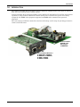
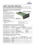
Liebert IntelliSlot
Web/485 Card
With Adapter
IS-WEBADPT
Liebert IntelliSlot Web Card
IS-WEBCARD, IS-WEBLB,
IS-WEBLBDS, IS-WEBNXL,
IS-WEBL, IS-IPBML,
IS-WEBS, IS-IPBMS
2
Compatibility With Other Emerson Products and Communication Protocols
Compatibility With Other Emerson Products and Communication Protocols
The Liebert IntelliSlot Web Card family, formerly the OpenComms line, includes:
Table 1
Compatibility With Liebert equipment
Liebert IntelliSlot Card
Part Number
Compatible with:
Liebert IntelliSlot Web Card
• Liebert GXT™
• Liebert GXT2U™ • Liebert PowerSure PSI™
(prior to July 2008)
IS-WEBCARD • Liebert GXT 6kVA&10kVA • Liebert Nfinity®
• Liebert GXT3™
Liebert IntelliSlot Web Card-LB
IS-WEBLB
Liebert IntelliSlot Web Card-LBDS
Units with Liebert iCOM Firmware prior to PA1.04.033.STD:
IS-WEBLBDS • Liebert Challenger 3000™ • Liebert CW™
• Liebert XDF™
™
™
• Liebert Challenger ITR
• Liebert DS
Liebert IntelliSlot Web Card NXL
IS-WEBNXL
• Liebert Hinet™
• Liebert NX™
®
Liebert IntelliSlot Web Card-L
IS-WEBL
Liebert IntelliSlot Web Card-IPBML IS-IPBML
Modbus IP / BACnet IP
• Liebert NXL™
• Liebert APM™
• Liebert HPC™ • Liebert XDP™
with Liebert iCOM
• Liebert CRV™
• Liebert HPM™
Units with Liebert iCOM Firmware PA1.04.033.STD or later:
• Liebert Challenger 3000 • Liebert Deluxe • Liebert PeX™
System/3™
• Liebert XDC™ with
• Liebert Challenger ITR
• Liebert DS
Liebert iCOM
• Liebert CW
Units with Velocity v4 control only:
• Liebert PPC™
• Liebert FDC™
™
• Liebert FPC
• Liebert RDC™
• Liebert AC Power and Precision Cooling systems not equipped with
IS-WEBADPT
a Liebert IntelliSlot port
Liebert IntelliSlot Web Card-S
IS-WEBS
Liebert IntelliSlot Web Card-IPBMS IS-IPBMS
Modbus IP
Liebert IntelliSlot Web/485 Card
With Adapter
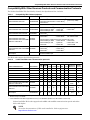
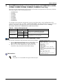
The Web cards support the following protocols:
Table 2
Liebert IntelliSlot card communication protocols
Communication Protocol
Liebert IntelliSlot Card
Part Number
SNMP SNMP
MODBUS IP/ LIEBERT
V3
HTTP HTTPS EMAIL SMS TELNET BACNET IP PROTOCOL
V1, V2C
Liebert IntelliSlot Web Card
IS-WEBCARD
✔
* ✔*
✔
✔
✔
✔
✔
—
—
Liebert IntelliSlot Web Card-LB
IS-WEBLB
✔
—
✔
✔
✔
✔
✔
—
—
Liebert IntelliSlot Web Card-LBDS
IS-WEBLBDS
✔
—
✔
—
—
—
✔
—
—
Liebert IntelliSlot Web Card NXL
IS-WEBNXL
✔
—
✔
✔
✔
✔
✔
—
✔
Liebert IntelliSlot Web Card-L
IS-WEBL
✔
—
✔
✔
✔
✔
✔
—
✔
Liebert IntelliSlot Web Card-S
IS-WEBS
✔
—
✔
✔
✔
✔
✔
—
✔
✔
Liebert IntelliSlot Web Card-IPBML
IS-IPBML
Modbus IP / BACnet IP
—
—
✔
✔
—
—
✔
✔
Both
Liebert IntelliSlot Web Card-IPBMS
IS-IPBMS
Modbus IP
—
—
✔
✔
—
—
✔
**✔**
Modbus
IP only
✔
Liebert IntelliSlot Web/485 Card
With Adapter
✔
—
✔
✔
—
—
✔
***✔***
✔
IS-WEBADPT
* SNMP v3 available for Liebert GXT3 only
** Modbus IP only for IS-IPBMS
*** Liebert DataMate & Mini-Mate support BACnet IP only on IS-WEBADPT (Modbus IP is not available on these units).
Liebert IntelliSlot Web cards support both 10Mbit and 100Mbit communication speeds and either
half or full duplex.
NOTE
See online demonstrations of Web cards installed in Liebert equipment at:
http://demos.liebert.com
3
Compatibility With Other Emerson Products and Communication Protocols
1.1
Web Support
The Liebert IntelliSlot Web card delivers Web management and control to Liebert equipment. All
authorized users on your network will be able to view status information.
1.2
Password Protection
Control and configuration capabilities are protected by a username and password combination.
Optionally, status information can be password-protected. The default username is “Liebert” and the
default password is also “Liebert.”
You can change the password using the terminal emulation, Telnet or Web interface. See 5.7 Change Username / Password - Administrator and General User for details.
NOTE
Change the username and password today to prevent unauthorized access.
1.3
SNMP Support
The Liebert IntelliSlot Web card enables SNMP management of Liebert equipment. To integrate the
card into your SNMP implementation, compile the Liebert Global Products MIB on your network
management station (NMS).
The Liebert Global Products MIB is included in this package on CD-ROM and supports both Windows
and Unix file formats.
1.4
Liebert Nform™ Support
Utilizing the SNMP and Web technologies built into each of the Liebert IntelliSlot Web cards, Liebert
Nform will centrally manage alarm notifications to provide you with an easy interface to access critical equipment information.
A downloadable edition is available online at:
nform.liebert.com
1.5
Liebert MultiLink™ Support
The Liebert IntelliSlot Web card integrates with Liebert’s MultiLink software to provide unattended,
graceful operating system shutdown of PCs, servers and workstations. The card can be monitored by
MultiLink over the network, eliminating the need for serial cables.
For more information on MultiLink and a downloadable version of MultiLink software, visit the
MultiLink page at:
multilink.liebert.com
1.6
Liebert SiteScan® Web With Modbus Support (Units with IS-WEBADPT Only)
The Liebert IntelliSlot Web/485 Card With Adapter integrates with Liebert SiteScan Web software
using Modbus to monitor trends for analysis and maintenance to ensure high-availability operation of
critical facilities.
For more information on SiteScan Web and Modbus integration, visit the SiteScan Web page at:
sitescan.liebert.com
4
Installation
2.0
INSTALLATION
! WARNING
Only a qualified service professional should install these products. Emerson recommends
having a Liebert Services representative perform the installation in large UPSs. Contact
Liebert Services at 1-800-LIEBERT (1-800-543-2378).
2.1
Install a Liebert IntelliSlot Web Card—Non-Adapter Version
Follow these steps to install a Liebert IntelliSlot Web card (non-adapter version—P/N IS-WEBCARD,
IS-WEBLB, IS-WEBLBDS, IS-WEBNXL, IS-WEBL, IS-IPBML, IS-WEBS and IS-IPBMS).
1. Locate the Liebert IntelliSlot option bay on your Liebert equipment—You might need to remove a
plastic cover.
2. Insert the Liebert IntelliSlot Web Card into the Liebert IntelliSlot bay.
3. Secure the card with the supplied screws.
4. Connect an Ethernet cable.
DHCP: The card ships with DHCP service enabled. The MAC address is on a
sticker on the top of the card.
OR
Static IP: To assign a static IP address or hostname, use terminal emulation
software to configure the card, as described in Sections 2.1.1 and 2.1.2.
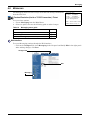
2.1.1
Connect the Cable
• Connect a configuration cable (null modem) to the DB-9 port on the card and to
a COM port on your PC. The configuration cable is available separately from
Emerson (P/N LIEBNULL).
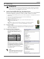
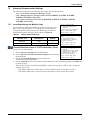
2.1.2
Prepare the Card for Configuration
• Use terminal emulation software, such as
Microsoft® HyperTerminal, to open a
connection to the card with the settings in
Table 3.
Table 3
Communication settings
Baud Rate:
Data Bits:
Parity:
Stop Bits:
Flow Control:
9600
8
None
1
None
• Press the Enter key for the Main Menu, above
right.
• Select IP Network Settings, then Boot/IP
Settings and follow the instructions to enter
an IP ADDRESS, NETMASK and GATEWAY.
• Press Esc to return to the Main Menu.
• Choose Exit and Save to save your changes
and reboot the card.
NOTE
When installing the card in a Liebert NX,
configure the communication port of the
Liebert NX to 2400 baud. See the Liebert
NX user manual for details.
5
Installation
2.2
Install a Liebert IntelliSlot Web/485 Card With Adapter
! WARNING
Risk of electric shock. Can cause equipment damage, injury or death.
Service and maintenance work must be performed only by properly trained and qualified
personnel and in accordance with applicable regulations and manufacturers’ specifications.
Opening or removing the covers to any equipment may expose personnel to lethal voltages
within the unit even when it is apparently not operating and the input wiring is disconnected
from the electrical source.
Check the circuits with a voltmeter before beginning installation.
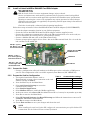
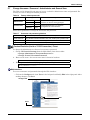
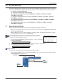
Follow these steps to install a Liebert IntelliSlot Web/485 Card With Adapter (P/N IS-WEBADPT).
• Locate the adapter mounting location in your Liebert equipment.
• Secure the Liebert IntelliSlot Web/485 Card With Adapter with the supplied screws.
• Connect the equipment's communication cable to the TB1 terminal block or P1 on the card (see
the user manual for the Liebert power or cooling unit for details).
• Connect a Modbus (RS-485) cable to the TB2 terminal block.
• Connect an input power supply cable to Pins 1 & 2 on the TB3 terminal block; Pin 1 is at the far
left, and Pin 2 is the middle pin.
P1
TB3 (P1: +) (P2: -)
(P3: NC) P1 is on left
end of terminal block.
Network Port for NMS
and Web Access
TB2 (P1: +) (P2: -);
P1 is at the right side
of the terminal block.
DB-9 Port
TB1 (P1: +; P2: -); P1
is at the right side of
the terminal block.
MAC Address
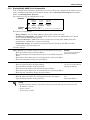
2.2.1
Connect the Cable
• Connect a configuration cable (null modem) to the DB-9 port on the card and to a COM port on
your PC. The configuration cable is available separately from Emerson (P/N LIEBNULL).
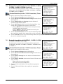
2.2.2
Prepare the Card for Configuration
Table 4
Communication settings
1. Use terminal emulation software, such as
Baud Rate: 9600
HyperTerminal, to open a direct connection to the card
Data Bits: 8
with the settings in Table 4.
Parity: None
2. Press the Enter key for the Main Menu.
Stop
Bits: 1
3. Select 485 Network Settings to access the
Flow Control: None
communications settings.
4. Select Enabled Application.
5. Select Modbus Server to enable the Modbus application.
6. At the next screen, select Server ID (the default Server ID is 1, but may be any number up to 255).
7. Press Esc to return to the Main Menu.
8. Select IP Network Settings, then Boot/IP Settings and follow the instructions to enter an IP
ADDRESS, NETMASK and GATEWAY.
9. Press Esc to return to the Main Menu.
10. Choose Exit and Save to save your changes and reboot the card.
NOTE
When installing the card in a Liebert NX, configure the communication port of the Liebert NX
to 2400 baud. See the Liebert NX user manual for details.
6
Configuration Overview
3.0
CONFIGURATION OVERVIEW
You may use any of the following interfaces to configure the Web card:
Table 5
Configuration interfaces
Interface
Icon
Description
Available
Functions
Connection
Methods
Terminal Emulation
(Serial or TCP/IP)
Use terminal emulation software
—for example, HyperTerminal.
Configuration
Serial Cable
or TCP/IP
Telnet
Use a command prompt—enter
“telnet” and the IP address or hostname.
Configuration
TCP/IP
Web
Use a Web browser—for example,
Microsoft® Windows® Internet Explorer®.
Configuration,
Monitoring, Control
TCP/IP
Each configuration section provides instructions using the Terminal Emulation (Serial or TCP/IP
Connection) / Telnet Interface, along with a brief description of how to access the same function
through the Web Interface.
NOTE
The Terminal Emulation and Telnet interfaces present the same menus and choices.
3.1
Guide to Configuration
Refer to the following guide for details on configuration functions. Sections 3.4 to 3.5 describe how to
get started with each interface.
Table 6
Guide to configuration details
Topic
Page:
Section
3.2 - Open the Terminal Emulation Interface - Serial Connection
8
Connecting
to an interface
3.3 - Open the Terminal Emulation Interface - TCP/IP Connection
9
3.4 - Open the Telnet Interface
10
3.5 - Open the Web Interface
11
Saving configuration changes
3.6 - Saving Changes and Reinitializing the Web Card
12
4.0 - Equipment Information
13
5.0 - Network Settings
14
6.0 - Messaging
36
7.0 - Factory Settings
40
Appendix A - - Firmware Updates
A1
Performing
configuration
functions
7
Configuration Overview
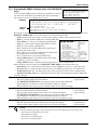
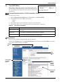
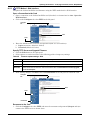
3.2
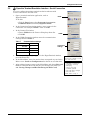
Open the Terminal Emulation Interface - Serial Connection
To access configuration using terminal emulation software with
a serial connection to the Web card:
1. Open a terminal emulation application, such as
HyperTerminal.
Name
To do this:
• Click the Start button, then Programs, Accessories,
Communications and finally HyperTerminal.
2. In the Connection Description window, enter a name for the
connection—for example, GXT2U—then click OK.
3. In the Connect To window:
• Choose COM3 from the Connect Using drop-down list.
• Click OK.
COM3
4. In the COM3 Properties window, enter the communication
settings shown in Table 7.
Table 7
Communication settings
Baud Rate:
Data Bits:
Parity:
Stop Bits:
Flow Control:
9600
Connection
settings
8
None
1
None
5. When the message at right appears in the HyperTerminal window,
press the Enter key.
6. In the Main Menu, enter the number that corresponds to your choice.
Refer to 3.1 - Guide to Configuration for details on each function.
7. After making changes, return to the Main Menu and choose Exit and
Save to reboot the Web card and put your changes into effect (see
3.6 - Saving Changes and Reinitializing the Web Card).
RTCS v2.96.00 Telnet server
Service Port Manager Active
<Esc> Ends Session
Main Menu
---------1: Equipment Information
2: IP Network Settings
3: Messaging
4: Factory Settings
5: Firmware Updates
q: Quit and abort changes
x: Exit and save
Please select a key ?>
8
Configuration Overview
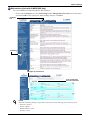
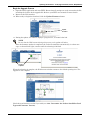
3.3
Open the Terminal Emulation Interface - TCP/IP Connection
To access configuration using terminal emulation software with
an Ethernet connection to the Web card:
1. Open a terminal emulation application, such as
Name
HyperTerminal.
To do this:
• Click the Start button, then Programs, Accessories,
Communications and finally HyperTerminal.
2. In the Connection Description window, enter a name for the
connection—for example, GXT2U—then click OK.
3. In the Connect To window:
• Choose TCP/IP (Winsock) from the Connect Using
drop-down list.
TCP/IP
• Enter the IP address or hostname of the Web card—for
(Winsock)
example, 192.168.0.125—in the Host Address box, then
click OK.
4. When the message at right appears in the HyperTerminal window,
RTCS v2.96.00 Telnet
press the Enter key.
Service Port Manager
<Esc> Ends Session
5. Enter the Administrator username and password (both are casesensitive):
a. Login (username—default is Liebert)
Login: Liebert
Password: ********
b. Password (default is Liebert)
server
Active
NOTE
For security, change the default username and password (see 5.7 - Change Username /
Password - Administrator and General User).
6. In the Main Menu, enter the number that corresponds to your choice.
Refer to 3.1 - Guide to Configuration for details on each function.
7. After making changes, return to the Main Menu and choose Exit and
Save to reboot the Web card and put your changes into effect (see
3.6 - Saving Changes and Reinitializing the Web Card).
Main Menu
---------1: Equipment Information
2: IP Network Settings
3: Messaging
4: Factory Settings
5: Firmware Updates
q: Quit and abort changes
x: Exit and save
Please select a key ?>
9
Configuration Overview
3.4
Open the Telnet Interface
To access configuration using Telnet:
1. Open a Telnet connection on a computer with an Ethernet connection to the Liebert unit.
To do this:
• Open a command prompt window—click the Start button, then
Run.
• Enter cmd and click OK.
• In the command prompt window that opens, enter telnet
followed by a space and the IP address or hostname of the Web card—for example:
telnet 192.168.0.125
C:>telnet 192.168.0.125
2. When the message at right appears in the command prompt window,
press the Enter key.
3. Enter the Administrator username and password (both are casesensitive):
a. Login (username—default is Liebert)
RTCS v2.96.00 Telnet server
Service Port Manager Active
<Esc> Ends Session
Login: Liebert
Password: ********
b. Password (default is Liebert)
NOTE
For security, change the default username and password (see 5.7 - Change Username /
Password - Administrator and General User).
4. In the Main Menu, enter the number that corresponds to your choice.
Refer to 3.1 - Guide to Configuration for details on each function.
5. After making changes, return to the Main Menu and choose Exit and
Save to reboot the Web card and put your changes into effect (see
3.6 - Saving Changes and Reinitializing the Web Card).
Main Menu
---------1: Equipment Information
2: IP Network Settings
3: Messaging
4: Factory Settings
5: Firmware Updates
q: Quit and abort changes
x: Exit and save
Please select a key ?>
10
Configuration Overview
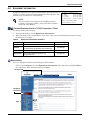
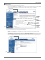
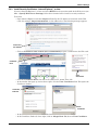
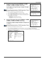
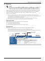
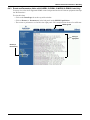
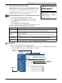
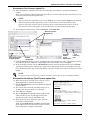
3.5
Open the Web Interface
To access configuration using the Web interface:
Configure tab
1. Open a Web browser such as Internet Explorer, then
enter the IP address or hostname of the Web card in the
address bar—e.g., http://192.168.0.125.
2. Click on the Configure tab, shown at right.
Configuration Categories appear in the left panel,
organized with folder icons.
3. Click on any configuration category, and the Connect To
box opens.
4. Enter the Administrator username and password (both
case-sensitive):
a. User Name (default is Liebert)
b. Password (default is Liebert)
NOTE
For security, change the default username and
password (see 5.7 - Change Username /
Password - Administrator and General
User).
5. Click OK.
6. Refer to 3.1 - Guide to Configuration for details on
each function.
7. After making changes, click the Save button, then click
on Reinitialize to reboot the Web card and put your
changes into effect (see 3.6 - Saving Changes and
Reinitializing the Web Card).
11
Configuration
Categories
Connect To
Reinitialize
(to save any changes)
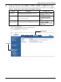
Configuration Overview
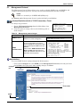
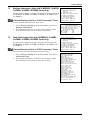
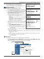
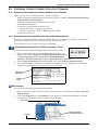
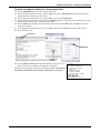
3.6
Saving Changes and Reinitializing the Web Card
Follow the applicable steps for your interface to save configuration changes and reinitialize the Web
card. Changes will not take effect until these steps are completed.
Terminal Emulation (Serial or TCP/IP Connection) / Telnet
• After each change is made, a reminder appears (shown at right).
• Return to the Main Menu, then choose Exit and Save. A
message appears and remains until the card is reinitialized,
followed by a message that the process was successful.
New Settings will take effect
when saved
GO TO MAIN MENU AND DO 'EXIT AND
SAVE' TO SAVE YOUR CHANGES!
Exiting and saving...
Configuration saved successfully
Web Interface
• After making each change, click the Save button. A reminder
appears each time you make a change (shown at right).
• Without leaving the Configure tab window (below left), click
Reinitialize in the left panel, then click the Reinitialize
button at right to reboot the Web card and put your changes
into effect.
Progress message window
First click
Reinitialize
at left
Then click
Reinitialize
button
• A message window appears, shown above right, and remains until the card is reinitialized.
12
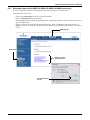
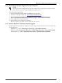
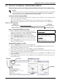
Equipment Information
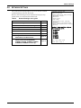
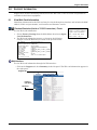
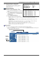
4.0
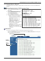
EQUIPMENT INFORMATION
Equipment Information is optional and identifies the Liebert unit, its
location, a contact person and other information about the unit. The
default value of each field is “Uninitialized.”
NOTE
This information also configures the SNMP parameters
sysName, sysContact, sysDescr, and sysLocation available
using RFC-1213 MIB II.
Equipment Information Menu
--------------------------1: Name
Uninitialized
2: Contact
Uninitialized
3: Location
Uninitialized
4: Description
Uninitialized
<ESC>: Cancel menu level
Please select a key ?>
Terminal Emulation (Serial or TCP/IP Connection) / Telnet
To edit any field in this category:
1. From the Main Menu, choose Equipment Information.
2. Enter the number that corresponds to your choice, then enter the identifying information, using
the following as a guide.
Table 8
Equipment Information identifiers
Item
Description
Maximum Length*
Name
A name for the Liebert unit
255 characters
Contact
A contact person or department responsible
for maintenance and operation of the Liebert unit
64 characters
Location
The location of the Liebert unit
64 characters
Description
Other useful information about the unit
for quick reference
64 characters
* Valid characters include spaces and other printable characters except double quotes (").
Web Interface
To access Equipment Information through the Web interface:
• Click on the Configure tab, then Equipment Information in the left panel and finally Edit in
the right panel. After making changes, click Save.
Configure tab
Equipment
Information
Edit
13
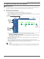
Network Settings
5.0
NETWORK SETTINGS
The IP Network Settings Menu is used to enable network
communications with the Web card.
Refer to the following sections for detailed step-by-step
instructions on each item from this menu:
Table 9
Network Settings menu guide
Menu item
Refer to:
5.1 - Boot/IP Settings
page 15
5.2 - Domain Name Server (DNS) Settings
page 16
5.3 - Management Protocol
page 18
5.4 - Web Server
page 27
5.5 - Telnet Server
page 32
5.6 - Time (SNTP) Menu
page 33
5.7 - Change Username / Password Administrator and General User
page 34
5.8 - Reset WEB Authentication to Factory
Defaults (Units with IS-WEBCARD,
IS-WEBL, IS-IPBML, IS-WEBS, IS-IPBMS,
IS-WEBLB, IS-WEBNXL Cards Only)
page 35
14
IP Network Settings Menu
------------------------1: Boot/IP Settings
2: Domain Name Server (DNS) Settings
3: Management Protocol
4: Web Server
5: Telnet Server
6: Time (SNTP)
7. Change Administrator Username/
Password
8: Change General Username/Password
9: Reset WEB Authentication to Factory
Defaults
Option 9 above applies only to
the following cards:
• IS-WEBCARD
• IS-WEBL
• IS-IPBML
• IS-WEBS
• IS-IPBMS
• IS-WEBLB
• IS-WEBNXL
<ESC>: Cancel menu level
Please select a key ?>
Network Settings
5.1
Boot/IP Settings
The Boot/IP Settings Menu is used to set parameters for network
access to the Web card. Consult your network administrator for these
settings.
Terminal Emulation (Serial or TCP/IP Connection) / Telnet
Boot/IP Settings Menu
---------------------1: Speed/Duplex
Auto
2: Boot mode
Static
3: IP Address
192.168.0.125
4: Netmask
255.255.255.0
5: Default Gateway 192.168.0.1
6: DNS Server
0.0.0.0
<ESC>: Cancel menu level
Please select a key ?>
To change any parameter:
1. Choose IP Network Settings from the Main Menu, then Boot/IP Settings.
2. Select an option to change—for example, Speed/Duplex, then enter settings according to the
following guide.
Table 10 Boot/IP settings range
Parameter
Speed/ Duplex
Boot Mode
IP address
Netmask
Default Gateway
DHCP/BootP Server
DNS Server
Description & Valid Settings*
Speed and duplex configuration of the Ethernet port.
• Auto (default—use this setting if unknown)
• 10Mbs/Half Duplex
• 100Mbs/Half Duplex
• 10Mbs/Full Duplex
• 100Mbs/Full Duplex
Startup mode enabling the Web card to be a network-ready device.
• Static - Fixed network addresses and other parameters
• DHCP - Central management using dynamic network addresses
• BootP - Older mechanism for central management of network addresses
Network address for the Liebert unit.
Four numbers (0-255) separated by periods (.)—for example, 10.0.0.5
Network mask that divides your network into manageable segments.
Four numbers (0-255) separated by periods (.)—e.g., 255.255.255.0
IP address of the gateway for network traffic to other networks or subnets.
Four numbers (0-255) separated by periods (.)—e.g., 10.0.0.1
Device on a network that assigns IP addresses that are not static.
Four numbers (0-255) separated by periods (.)—for example, 192.168.0.5
IP address of the Domain Name Server for the network.
Four numbers (0-255) separated by periods (.)—e.g., 10.0.0.1
* Consult your network administrator for proper settings.
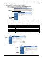
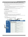
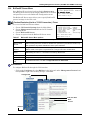
Web Interface
To access Boot/IP Settings through the Web interface:
• Click on the Configure tab, then Network Settings in the left panel and finally Edit beneath
the table of parameters and descriptions. After making changes, click Save.
Configure tab
Network
Settings
Edit
15
Network Settings
5.2
Domain Name Server (DNS) Settings
The Domain Name Server settings menu configures the servers the Web card will use for hostname
resolution. When configured, host addresses for SNMP, Network Time and Email/SMS can be specified in either full Domain Name format or in host-only format, provided that the appropriate Domain
Name Suffix is used.
The DNS menu is used to set parameters for network access to the Web card. Consult your network
administrator for these settings.
Terminal Emulation (Serial or TCP/IP Connection) / Telnet
To change any parameter:
1. Choose IP Network Settings from the Main Menu, then Domain Name Server (DNS)
Settings.
2. Select an option to change—for example, DNS Mode, then enter settings according to the
following guide.
Table 11
Domain Name Server settings
Parameter
Description & Valid Settings *
DNS Mode
Obtain DNS server addresses automatically or use specified addresses.
Note: Automatic assignment option is available only if a DHCP server is used to assign
IP information to the Web Card.
Primary DNS
Primary IP address of the name server for network.*
Four numbers (0-255) separated by periods (.)—e.g., 192.168.0.1
Secondary DNS
Secondary IP address of the name server for network.*
Four numbers (0-255) separated by periods (.)—e.g., 192.168.0.1
DNS Resolve Interval
Interval to resolve DNS addresses from a network name to an IP address.
Domain Name Suffix
This suffix is used for assembling a fully qualified domain name when a host-only name
is specified.
DNS Test
Checks whether the Web card will resolve a hostname to an IP address. Provide a hostonly name, a fully qualified domain name or an IP address, click on Query for the card to
attempt a lookup with the provided information.
* Consult your network administrator for proper settings.
16
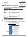
Network Settings
Web Interface
To access the DNS menu through the Web interface:
• Click on the Configure tab, then DNS in the left panel under Network Settings and finally Edit
beneath the table of parameters and descriptions. After making changes, click Save.
Configure tab
Click Edit
to change
settings
Obtain
address
automatically
Specify
address
How long
card retains
resolved
addresses
DNS
To access the DNS Test menu through the Web interface:
• Click on the Configure tab, then Test in the left panel under DNS in the Network Settings
group.
• Choose the Type of DNS from the drop-down list—Hostname, Fully Qualified Domain Name
or IP Address. In the Question box, enter a value for the DNS to answer.
• Click on the Query button. The DNS response will appear adjacent to the Last Query Response.
Configure tab
Test
17
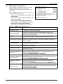
Network Settings
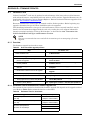
5.3
Management Protocol
The Management Protocol Menu allows you to enable or disable SNMPv1/v2c and SNMPv3 and
configure management protocols. Consult your network administrator for these settings.
NOTE
SNMP v3 is available for IS-WEBCARD (HID9) only.
See Section 10 for Management Protocol options for BACnet and Modbus.
Terminal Emulation (Serial or TCP/IP Connection) / Telnet
To change any parameter:
1. Choose IP Network Settings from the Main Menu, then
Management Protocol.
2. Select an option to change, then use the following guide to
make changes.
Table 12
Management Protocol Menu
------------------------1: SNMPv1/v2c Protocol
enabled
2: SNMPv3 Protocol
enabled
3: SNMP Communications
<ESC>: Cancel menu level
Please select a key ?>
Management protocol ranges
Parameter
SNMP Protocol
SNMP
Communications
Description & Telnet Menus
Enable or disable SNMPv1/v2c or
SNMPv3 for remote management.
Enable SNMPv1/v2c Protocol? [y/n] ?>
The SNMP Communications Menu
(shown at right) allows you to set up
access privileges and configure the Web
card to send traps for SNMPv1/v2c and
SNMPv3.
SNMP Communications Menu
------------------------1: Authentication Traps
yes
2: RFC-1628 (UPS) MIB
enabled
3:
- Traps
enabled
4: Liebert Global Products MIB enabled
5:
- Condition Traps
enabled
6:
- System Notify Trap
enabled
7: Heartbeat Trap Interval
24 hours
8: Display/Modify SNMPv1/v2c Communities
9: Display/Modify SNMPv1/v2c Trap Communities
A: Display/Modify SNMPv3 Settings
B: Support Information
Refer to 5.3.1 - SNMP Communications
Menu and Table 13 in that section for
details and additional references to more
information on these options.
Enable SNMPv3 Protocol? [y/n] ?>
<ESC>: Cancel menu level
Please select a key ?> 1
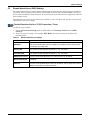
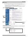
Web Interface
To access SNMP Protocol settings through the Web interface:
• Click on the Configure tab, then SNMP (under Management Protocol) in the left panel and
finally Edit in the right panel. After making changes, click Save.
Configure
tab
Click on Edit
SNMP
18
Network Settings
5.3.1
SNMP Communications Menu
Use the SNMP Communications Menu to enable
authentication traps and view or change
communities and trap communities, events and
parameters.
Refer to Table 13 for details on each menu option, as
well as the following sections:
• Section 5.3.2 - Display/Modify SNMPv1/v2c
Communities
• Section 5.3.3 - Display/Modify SNMPv1/v2c
Trap Communities
• Section 5.3.4 - Display/Modify SNMPv3
Settings (Units with IS-WEBCARD Only)
• Section 9.2 - Events and Parameters
(for details on viewing Support Information)
Table 13
SNMP Communications Menu
------------------------1: Authentication Traps
yes
2: RFC-1628 (UPS) MIB
enabled
3:
- Traps
enabled
4: Liebert Global Products MIB
enabled
5:
- Condition Traps
enabled
6:
- System Notify Trap
enabled
7: Heartbeat Trap Interval
24 hours
8: Display/Modify SNMPv1/v2c Communities
9: Display/Modify SNMPv1/v2c Trap Communities
A: Display/Modify SNMPv3 Settings
B: Support Information
<ESC>: Cancel menu level
Please select a key ?> 1
SNMP communications menu
Parameter
Description & Telnet Menus
Authentication Traps
Enables authentication traps to receive security alerts when the Web card detects
a request with an invalid community string.
RFC-1628 (UPS) MIB
Enables the RFC-1628 (UPS specific information) MIB on the Web card for
querying of information in that MIB. This can be enabled or disabled independently
of the Liebert Global Products MIB.
• Traps
This option enables the RFC-1628 traps to be sent when an alarm event occurs on
the device. The parent option must be enabled for this to also be enabled.
Liebert Global Products MIB
Enables the Liebert Global Products MIB (Enterprise Specific) for querying of
information in that MIB. This option can be enabled or disabled independently of
the RFC-1628 MIB.
• Condition Traps
Enables event condition traps to be sent per the LGP MIB. The parent option must
be enabled for this to also be enabled.
• System Notify Trap
Enables system traps to be sent per the LGP MIB. The parent option must be also
enabled for this to be enabled.
Heartbeat Trap Interval
Specifies how often a heartbeat trap will be sent to show that the device is online
and functioning normally.
Display/Modify SNMPv1/v2c
Communities
View devices that have permission to access the Web card, identified by IP
address or hostname, read/write permission and community string. Up to 20
devices may be configured for access.
See 5.3.2 - Display/Modify SNMPv1/v2c Communities.
Display/Modify SNMPv1/v2c
Trap Communities
View devices that are configured to receive notifications from the Web card,
identified by IP address or hostname, trap listen port and community string. Up to
20 devices may be configured to receive traps.
See 5.3.3 - Display/Modify SNMPv1/v2c Trap Communities.
Display/Modify SNMPv3
Settings
View devices that have permission to access the Web card, identified by IP
address and other parameters.
See 5.3.4 - Display/Modify SNMPv3 Settings (Units with IS-WEBCARD Only).
Support Information
View a list of all supported events and parameters for the Liebert equipment
through any interface. Depending on the Liebert IntelliSlot Web card, the list might
include SNMP, Modbus or BACnet.
See 9.2 - Events and Parameters.
19
Network Settings
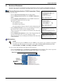
Web Interface
To access SNMP Communications settings (for Authentication Traps, RFC-1628 (UPS) MIB, Liebert
Global Products MIB and Heartbeat Trap Interval options) through the Web interface:
• Click on the Configure tab, then SNMP in the left panel (under Management Protocol) and
finally Edit in the right panel. After making changes, click Save.
• Note the options vary according to the type of equipment. RFC-1628 MIB features are available
for UPS/Power equipment only—not for Precision Cooling and other equipment, as shown at
bottom in the examples below.
Configure
tab
Management
Protocol
Click on Edit
to enable any
options
Interval choice
sets the
frequency of
Heartbeat
Traps
OPTIONS FOR UPS/POWER EQUIPMENT
(includes RFC-1628 MIB features—retrieving data from RFC-1628 MIB objects and sending RFC-1628 MIB traps)
OPTIONS FOR PRECISION COOLING/OTHER EQUIPMENT
(does NOT include RFC-1628 MIB features)
20
Network Settings
5.3.2
Display/Modify SNMPv1/v2c Communities
View or modify devices that have permission to access the Web card, identified by IP address or hostname, read/write permission and community string. Choose IP Network Settings from the Main
Menu, then Management Protocol.
Up to 20 devices may be configured for access.
EXAMPLE
Codes for
editing
Communities
-----------1:
10.0.0.5
2:
10.0.0.6
Entry
#
IP
address
write
write
public1
public1
Access
Community
(read/write)
string
<a>dd <d>elete <e>dit
Complex lines allowed. e.g. <a 198.1.1.1 write public> ?>
Each device is identified by:
• Entry Number - use the entry number (1-20) to edit or delete an entry
• IP address or Hostname - the address of the device with access (MultiLink server, Nform
server, Network Management System)
• Access (read/write) - read allows users to view but not change data; write allows full
permission for configuration, control and viewing
• Community string - the community string used by the IP host for this Entry Number
(case-sensitive, up to 32 characters)
To make changes:
Add a device (see example at right to enter all parameters in one line): Example
a 10.0.0.5 write public1
• Enter a to add an entry, then press Enter.
• Enter the IP address or hostname of the device to be added, then press (then press Enter)
Enter.
• Enter 1 for read or 2 for write access for this device, then press Enter.
• Enter the community string, then press Enter.
Edit a device (see example at right to enter all parameters in one line): Example
e 2 10.0.0.7 read public2
• Enter e to edit an entry, then press Enter.
(then press Enter)
• Type the Entry Number, then press Enter.
• Enter the new IP address or hostname, then press Enter.
• Enter 1 for read or 2 for write access for this device, then press Enter.
• Enter the new community string, then press Enter.
Delete a device (see example at right to enter parameters in one line):
• Enter d, then press Enter. No confirmation message will appear.
• Type the Entry Number, then press Enter.
Example
d2
(then press Enter)
NOTE
Avoid the following setting—it permits access by any host and may pose a security risk:
• IP address = 0.0.0.0
• Access = write
• Community = public
21
Network Settings
Web Interface
To access SNMPv1/v2c Communities settings through the Web interface:
• Click on the Configure tab, then Access or V1 Access (under Management Protocol) in the
left panel and finally Edit in the right panel. After making changes, click Save.
Configure
tab
Click on Edit
V1 Access
Configure up to 20 devices for read/write access
NOTE
Avoid the following setting—it permits access by any host and may pose a security risk:
• Network Name = 0.0.0.0
• Access = write
• Community = public
22
Network Settings
5.3.3
Display/Modify SNMPv1/v2c Trap Communities
View or modify devices that are configured to receive notifications from the Web card, identified by IP
address or hostname, trap listen port and community string.
Up to 20 devices may be configured to receive traps.
EXAMPLE
Trap Communities
----------------1:
10.0.0.5
2:
10.0.0.6
Entry
#
Codes for
editing
IP
address
162
162
public1
public1
Port to
Community
receive traps
string
<a>dd <d>elete <e>dit
Complex lines allowed. e.g. <a 198.1.1.1 162 public> ?>
Each device is identified by:
• Entry Number - use the entry number (1-20) to edit or delete an entry
• IP address or hostname - the address or name of the device to receive traps (MultiLink server,
Nform server, Network Management System)
• Port - the Trap Listen Port where traps will be sent; use 162 if the host computer uses standard
ports (161/162)
• Community string - the community string used by the IP host for this Entry Number
(case-sensitive, up to 32 characters)
To make changes:
Add a device (see example at right to enter all parameters in one line): Example
a 10.0.0.5 162 public1
• Enter a to add an entry, then press Enter.
• Enter the IP address or hostname of the device to be added, then press (then press Enter)
Enter.
• Enter the port number (default is 162), then press Enter.
• Enter the community string, then press Enter.
Edit a device (see example at right to enter all parameters in one line):
• Enter e to edit an entry, then press Enter.
• Type the Entry Number, then press Enter.
• Enter the new IP address or hostname, then press Enter.
• Enter the port number (default is 162), then press Enter.
• Enter the new community string, then press Enter.
Example
Delete a device (see example at right to enter parameters in one line):
• Enter d, then press Enter. No confirmation message will appear.
• Type the Entry Number, then press Enter.
Example
23
e 2 10.0.0.7 162 public2
(then press Enter)
d2
(then press Enter)
Network Settings
Web Interface
To access SNMPv1/v2c Trap Communities settings through the Web interface:
• Click on the Configure tab, then Traps or V1 Traps (under Management Protocol) in the left
panel and finally Edit in the right panel. After making changes, click Save.
Configure
tab
Click on
Edit
Test Heartbeat
Trap
Traps
Configure up to 20 devices to receive traps
24
Network Settings
5.3.4
Display/Modify SNMPv3 Settings (Units with IS-WEBCARD
Only)
View or modify SNMPv3 devices that have permission to access
the Web card, identified by IP address and other parameters.
Display/Modify SNMPv3 Settings Menu
-----------------------------------Engine ID: 00000063000000a17e04145c
1: Display/Modify SNMPv3 Users
<ESC>: Cancel menu level
Please select a key ?> 1
Up to 20 devices may be configured for access.
EXAMPLE
Codes for
editing
Display/Modify SNMPv3 Users
---------------------------Num Enbl User Name
Auth Priv R W N Access Addresses
Notify Addresses
--- ---- ------------ ----- ---- - - - ------------------ -----------------1: YES Monitoring M MD5
DES Y Y Y 126.4.20.77
126.4.20.77
<ESC>: Cancel menu level
<a>dd <d>elete <e>dit <s>how <h>elp
Expert mode entry supported. Select <h>elp for details...
Make Selection: ?>
Each device is identified by these fields—numbers in parentheses correspond to field numbers in the
EDITING USER DATA screen where data may be edited (shown below):
•
•
•
•
•
•
Num (automatically generated) - use this entry number (1-20) to edit or delete an entry
Enbl (1) - Shows whether SNMPv3 is enabled (YES/NO) EDITING USER DATA
1: User Record Enabled..: YES
User Name (2) - name of user (Monitoring Marketing
2: User.................: Monitoring
Auth (3) - type of authorization (MD5/SHA-1/None)
Marketing
3: Auth Type............: MD5
Priv (4) - type of privacy (DES/None)
4: Priv Type............: DES
5: Read Allowed.........: YES
R (5) - Read access allowed (YES/NO); permission to
6: Write Allowed........: YES
7: Notifications Allowed: YES
view but not change data
8: Access Sources.......: 126.4.20.77
• W (6) - Write access allowed (YES/NO); full permission
9: Notification Targets.: 126.4.20.77
10: Auth Secret..........: LiebertLiebert
for configuration, control and viewing
11: Priv Secret..........: LiebertLiebert
12: Notification Port....: 162
• N (7) - Notifications access allowed (YES/NO)
13: Enable Heartbeat Trap: YES
• Access Addresses (8) - IP address of the device with
Enter # of field to edit, ‘0’ to commit
edits, or <ESC>: to discard edits ?>
read/write access as specified
• Notify Addresses (9) - IP address of the target device to receive notifications
Other fields that may be edited in the EDITING USER DATA screen shown above are:
• Auth Secret (10) - Password (8-64 characters) for Get SNMPv3 request (e.g., LiebertLiebert)
• Priv Secret (11) - Password (8-64 characters) for Get SNMPv3 request (e.g., LiebertLiebert)
• Notification Port (12) - the Trap Listen Port where traps will be sent (162 is standard port)
• Enable Heartbeat Trap (13) - notifications that the device is functioning normally (YES/NO)
To make changes:
Example
Add a device (see example at right):
a (press Enter)
• Enter a to add an entry, then press Enter.
• The EDITING USER DATA screen appears (shown above right). Enter the
field number of each item to be edited and make changes as needed.
• When finished, enter 0 (zero) to save changes (or Esc to exit without saving).
Example
Edit a device (see example at right):
e (press Enter)
• Enter e to edit an entry, then press Enter.
2 (press Enter)
• Type the Num (entry number) of the entry to be edited, then Enter.
• The EDITING USER DATA screen appears (shown above right). Enter the
field number of each item to be edited and make changes as needed.
• When finished, enter 0 (zero) to save changes (or Esc to exit without saving).
Delete a device (see example at right):
• Enter d, then press Enter. No confirmation message will appear.
• Type the Num (entry number) of the entry to be deleted, then Enter.
Example
d (press Enter)
2 (press Enter)
NOTE
Avoid the following setting—it permits access by any host and may pose a security risk:
• Access Sources (IP address) = 0.0.0.0
• Write Allowed = YES
• Auth Secret = LiebertLiebert
• Priv Secret = LiebertLiebert
25
Network Settings
Web Interface (Units with IS-WEBCARD Only)
To access SNMPv3 settings through the Web interface:
• Click on the Configure tab, then V3 Settings (under Management Protocol) in the left panel
and finally Edit in the right panel. After making changes, click Save.
Configure
tab
V3 Settings
Configure up to 20 devices
Click on Edit, then
Save when finished
NOTE
Avoid the following setting—it permits access by any host and may pose a security risk:
• Sources = 0.0.0.0
• Access = Write
• Authorization = none
• Privacy = none
26
Network Settings
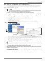
5.4
Web Server
Use the Web Server Menu to configure access to the card
through the Web interface. Consult your network administrator if needed.
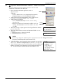
5.4.1
Specify Web Server Settings
Web Server Menu
---------------1: Web Server Mode
2: HTTP Transport Port
3: Password Protect Site
4: Configuration/Control
5: Refresh Rate
<ESC>: Cancel menu level
Please select a key ?>
HTTP (Not Secure)
80
'disabled'
'enabled'
30 seconds
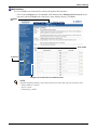
Terminal Emulation (Serial or TCP/IP Connection) / Telnet
To change any parameters:
1. Choose IP Network Settings from the Main Menu, then Web Server.
2. Select an option to change, then use the following guide to make changes.
Table 14
Web server settings
Parameter
Web Server
Mode
HTTP
Transport
Port
Description & Valid Settings
Select the operation mode of the Web server.
• Disabled - Web server is disabled
• HTTP - Standard Web port, not encrypted
• HTTPS - Standard secure Web port, all communication is encrypted
Web Server listening port number.
• For HTTP mode (non-encrypted communications), the default port is 80.
• For HTTPS mode (encrypted communications), the default port is 443.
For HTTPS, you must also install a security certificate for Internet Explorer. Refer to the appropriate section for your version of Internet Explorer:
•
•
5.4.2 - Install Security Certificates - Internet Explorer 6 or earlier
5.4.3 - Install Security Certificates - Internet Explorer 7 or later
Password
Protect Site
When enabled, the entire site is password-protected. (If disabled, all pages are accessible
without a password except configure and control functions.)
Configuration/
Control
Enable or disable the use of a Web browser to perform configuration and control operations.
Note: This feature affects configuration and control operations from the Web interface only. If
disabled, these functions may still be available using other system interfaces.
Refresh
Interval
The interval in seconds (10 to 600 seconds) between automatic updates of dynamic Web
pages—parametric data and device status in the right panel.
RECOMMENDATION: Consider whether frequent updates will slow down the system. If many
users will access the device simultaneously, select a larger value to best serve all users.
Recommended values range from 20 to 60 seconds.
Web Interface
To access Web Server settings through the Web interface:
• Click on the Configure tab, then Web in the left panel and finally Edit in the right panel. After
making changes, click Save.
Configure tab
Web
Edit
27
Network Settings
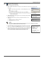
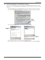
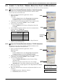
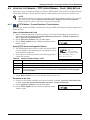
5.4.2
Install Security Certificates - Internet Explorer 6 or earlier
If you use Internet Explorer 6 or an earlier version and select HTTPS as the operation mode of the
Web server (see 5.4.1 - Specify Web Server Settings), follow these instructions to install a security
certificate.
• Open Internet Explorer and enter https:// followed by the IP address or hostname of the Web
card—for example, https://192.168.0.125—in the address bar. The following message appears.
Click on
View
Certificate
• Click the View Certificate button. This opens the Certificate window.
Certificate
Path tab
View
Certificate
• In the Certificate window, above left, click the Certificate Path tab.
• In the Certificate Path tab, above right, click on Allegro Root CA, then on View Certificate.
28
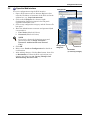
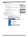
Network Settings
• In the Certificate window, click the Install Certificate button, as shown below.
Install
Certificate
• The Certificate Import Wizard opens. Click Next.
Automatically
select...
• Click on Automatically select the certificate store based on the type of certificate, then
click Next.
• The final Wizard window appears with a message that the process is complete. Click Finish.
• A confirmation box appears with a message that the import was successful. Click OK.
29
Network Settings
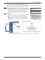
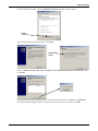
5.4.3
Install Security Certificates - Internet Explorer 7 or later
If you use Internet Explorer 7 or later and select HTTPS as the operation mode of the Web server (see
5.4.1 - Specify Web Server Settings), follow these instructions to install a security certificate.
To do this:
• Open Internet Explorer and enter https:// followed by the IP address or hostname of the Web
card—for example, https://192.168.0.125—in the address bar. The following message appears.
Continue to
this website
• Click on Continue to this website (not recommended) to open a connection to the Web card.
Certificate
Error
View
Certificates
• Click the Certificate Error box next to the address bar, shown above left.
• In the window that pops up, shown above right, click the View Certificates link. This opens the
Certificate window.
Certificate
Path tab
View
Certificate
• In the Certificate window, above left, click the Certificate Path tab.
• In the Certificate Path tab, above right, click on Allegro Root CA, then on View Certificate.
30
Network Settings
• In the Certificate window, click the Install Certificate button, as shown below.
Install
Certificate
• The Certificate Import Wizard opens. Click Next.
Automatically
select...
• Click on Automatically select the certificate store based on the type of certificate, then
click Next.
• The final Wizard window appears with a message that the process is complete. Click Finish.
• A confirmation box appears with a message that the import was successful. Click OK.
31
Network Settings
5.5
Telnet Server
Telnet Server Menu
------------------1: Telnet Server
Use the Telnet Server Menu to enable or disable access to the Web
card through a Telnet interface.
'enabled'
<ESC>: Cancel menu level
Please select a key ?>
Terminal Emulation (Serial or TCP/IP Connection) / Telnet
To change this setting:
1. Choose IP Network Settings from the Main Menu, then Telnet Server.
2. Choose Telnet Server, then specify:
• Enabled to permit Telnet access
• Disabled to block access via Telnet
Web Interface
To access Telnet settings through the Web interface:
• Click on the Configure tab, then Telnet in the left panel and finally Edit in the right panel.
After making changes, click Save.
Configure tab
Edit
Telnet
32
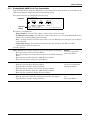
Network Settings
5.6
Time (SNTP) Menu
This permits setting time options—how often the Web card
synchronizes with the Time Server, which Time Server to use
for synchronization and which the Time Zone the Web card is
operating in.
Time Server Menu
------------------1: SNTP Time Sync Rate
2: Time Server
3: Time Zone
Hourly
time.nist.gov
(GMT) UTC
<ESC>: Cancel menu level
Please select a key ?>
Terminal Emulation (Serial or TCP/IP Connection) / Telnet
To change this setting:
1. Choose IP Network Settings from the Main Menu, then Time (SNTP).
2. Choose SNTP Time Synch Rate, then specify:
• Hourly
• Daily
3. Choose Time Server, then specify the new time server, if desired.
4. Choose Time Zone, select a region from the list and then select a time zone.
Table 15
Time Server parameters
Parameter
Description & Telnet Menus
SNTP Time Sync Rate
This is how often the card will attempt to synchronize its internal clock with the specified
time server.
Time Server
This is the server that will be used for synchronization. This can be either an IP address
or a hostname, provided that the DNS options are configured.
Time Zone
This is the local Time Zone that will be used to correctly adjust the time provided by the
server for the locale where the Web Card is being used.
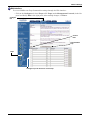
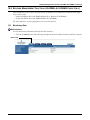
Web Interface
To access Time (SNTP) settings through the Web interface:
Click on the Configure tab, then Network Settings in the left panel and finally Edit in the right
panel. After making changes, click Save.
Configure
tab
Time
Server
list
Click on Edit
to choose
options
Time
Servers
must be
entered
manually
Time zones
available
from list
33
Network Settings
5.7
Change Username / Password - Administrator and General User
The Web card is designed for two types of access, each with a default user name and password. For
security, be sure to change the default password.
Table 16
Factory default passwords
Type of User
Administrator
General User
Factory Default
Username
Liebert
Password
Liebert
Username
User
Password
User
Description
Full access to configuration and control
functions, as well as viewing privileges
Viewing privileges only—no access to
configuration or control functions
Follow these guidelines to change the user name and password.
Table 17
Username and password guidelines
Maximum length
32 characters (6 or more characters recommended)
Valid characters
Any printable character EXCEPT colon, tab, double quote, question mark
Upper/lowercase
Case-sensitive—letters must be uppercase or lowercase as entered
Tips
Avoid common names, words and phrases as passwords
Terminal Emulation (Serial or TCP/IP Connection) / Telnet
To change the Administrator or General user name or password:
1. Choose IP Network Settings from the Main Menu, then choose either:
• Change Administrator Username/Password or
• Change General Username/Password
2. Enter a user name—the current user name is shown in brackets.
Enter Administrator Username, press enter for [Liebert]: (Max 32 chars) ?>
3. Enter a password, then verify by typing the password again.
Enter New Password: (Max 32 chars) ?> ********
Verify Password: ?> ********
Web Interface
To access usernames and passwords through the Web interface:
• Click on the Configure tab, then Users in the left panel and finally Edit in the right panel. After
making changes, click Save.
Configure tab
Edit
Users
34
Network Settings
5.8
Reset WEB Authentication to Factory Defaults (Units with IS-WEBCARD, IS-WEBL,
IS-IPBML, IS-WEBS, IS-IPBMS, IS-WEBLB, IS-WEBNXL Cards Only)
You may reset the Administrator and General User usernames and passwords to the factory defaults.
This option applies only to the following cards:
•
•
•
•
•
•
•
IS-WEBCARD
IS-WEBL
IS-IPBML
IS-WEBS
IS-IPBMS
IS-WEBLB
IS-WEBNXL
If you forget your username or password, you may reset them using a serial configuration cable
connection (see Section 2.1.1 or 2.2.1 - Connect the Cable), which provides direct access to the card
without a username or password. To enter a new username and password, see 5.7 - Change
Username / Password - Administrator and General User.
Table 18
Factory default passwords
Type of User
Administrator
General User
Factory Default
Username
Liebert
Password
Liebert
Username
User
Password
User
Description
Full access to configuration and control
functions, as well as viewing privileges
Viewing privileges only—no access to
configuration or control functions
Terminal Emulation (Serial or TCP/IP Connection) / Telnet
To reset the usernames and passwords to the factory defaults:
1. Choose IP Network Settings from the Main Menu, then
Reset WEB Authentication to Factory Defaults.
2. Enter y to reset the Administrator and General User
usernames and passwords to the default settings.
IP Network Settings Menu
------------------------1: Boot/IP Settings
2: Domain Name Server (DNS) Settings
3: Management Protocol
4: Web Server
5: Telnet Server
6: Time (SNTP)
7. Change Administrator Username/
Password
8: Change General Username/Password
9: Reset WEB Authentication to Factory
Defaults
<ESC>: Cancel menu level
Please select a key ?>9
Reset WEB Authentication to Factory
Defaults? [y/n] ?>
Web Interface
NOTE
This feature is not available through the Web interface.
35
Messaging
6.0
MESSAGING
The Messaging menu is used to set up e-mail and text message notifications
from the Web card.
Terminal Emulation (Serial or TCP/IP Connection) / Telnet
Messaging Menu
--------------1: Email 'disabled'
2: SMS
'disabled'
3: Email Configuration
4: SMS Configuration
To access these options:
<ESC>: Cancel menu level
1. Choose Messaging from the Main Menu.
2. Select an option, then use the following guide to make changes.
Table 19
Please select a key ?>
Messaging menu guide
Menu item
Refer to:
E-Mail Configuration
page 37
SMS Configuration
page 38
Customize Messages (E-Mail and SMS)
page 39
Web Interface
To access Messaging settings through the Web interface:
• Click on the Configure tab, then Messaging in the left panel and finally Edit in the right panel.
After making changes, click Save.
Configure tab
Edit
Messaging
36
Messaging
6.1
E-Mail Configuration
Setting up event notifications to be sent via e-mail involves two steps:
enabling the function, then specifying the parameters.
Terminal Emulation (Serial or TCP/IP Connection) / Telnet
To activate and set up e-mail messages:
1. Choose Messaging from the Main Menu, then Email.
Email Configuration Menu
------------------------1: Email From
'Uninitialized'
2: Email Message Recipients
3: Email Subject
4: Email Customize Message
5: SMTP Server 'Uninitialized'
6: Port
25
7: Test Email
8: View Test Email Log File
<ESC>: Cancel menu level
Please select a key ?>
Enable Email? [y/n] ?>
2. To enable the e-mail feature, enter y (yes) at the prompt.
3. Choose Email Configuration from the Messaging Menu, then select an option and use the
following guide to make changes.
Table 20
E-mail configuration guide
Parameter
Email From
Email Message
Recipients
Email Subject
Email Customize
Message
SMTP Server
Port
Test Email
View Test Email
Log File
Description
Maximum
The e-mail address of the sender—for example, [email protected]—
typically, the address where replies should be sent.
The e-mail will be sent to this list of addresses. To add an e-mail address, use
the format a [email protected]. Multiple addresses must be added individually.
Changes may be made by entering d to delete an entry or e to edit an entry.
NOTE: To specify multiple recipients of the e-mail message in the Web
interface, use a semicolon (;) to separate addresses in the Email To box.
The subject line of the e-mail. By default, this is the event description—e.g.,
AlarmOnBypass—but it may be customized.
The text of the message sent to e-mail recipients. Choose from a list of items to
include in the message. For details, see 6.3 - Customize Messages.
The IP address or domain name of the SMTP e-mail server that sends
messages.
SMTP server port—typically the default port, 25.
After saving changes to e-mail parameters, send a test e-mail message to verify
the settings are correct. The message status will be displayed.
64
characters
Choose this option to display a log showing the results of test e-mails.
64
characters
120
characters
—
32
characters
—
—
—
Web Interface
To access E-Mail Configuration through the Web interface:
• Click on the Configure tab, then Email in the left panel and finally Edit in the right panel.
After making changes, click Save.
Configure tab
Email
Edit
37
Messaging
6.2
SMS Configuration
Setting up event notifications for SMS text messages involves two
steps: enabling the function, then specifying the parameters.
Terminal Emulation (Serial or TCP/IP Connection) / Telnet
To activate and set up SMS messages:
1. Choose Messaging from the Main Menu, then SMS.
SMS Configuration Menu
----------------------1: SMS From
'Uninitialized'
2: SMS Message Recipients
3: SMS Subject
4: SMS Customize Message
5: SMTP Server 'Uninitialized'
6: Port
25
7: Test SMS
8: View Test SMS Log File
<ESC>: Cancel menu level
Please select a key ?>
Enable SMS [y/n] ?>
2. To enable the SMS feature, enter y (yes) at the prompt.
3. Choose SMS Configuration from the Messaging Menu, then select an option and use the
following guide to make changes.
Table 21
SMS configuration guide
Parameter
Description
Maximum
64
characters
SMS Customize
Message
The e-mail address of the sender—for example, [email protected]—
typically, the address where replies should be sent.
The message will be sent to this list of addresses. The SMS/Text Message
address is usually a 10-digit phone number followed by @____.com (where ____
might be a company name). To add an SMS address, use the format
a [email protected]. Multiple addresses must be added individually.
Changes may be made by entering d to delete an entry or e to edit an entry.
NOTE: To specify multiple recipients of the SMS message in the Web interface,
use a semicolon (;) to separate addresses in the SMS To box.
The subject line of the message. By default, this is the event description—e.g.,
AlarmOnBypass—but it may be customized.
The text of the message sent to e-mail recipients. Choose from a list of items to
include in the message. For details, see 6.3 - Customize Messages.
SMTP Server
The IP address or domain name of the SMTP e-mail server that sends messages.
Port
SMTP server port—typically the default port, 25.
After saving changes to SMS parameters, send a test SMS message to verify the
settings are correct. The message status will be displayed.
SMS From
SMS Message
Recipients
SMS Subject
Test SMS
View Test
SMS Log File
Choose this option to display a log showing the results of test messages.
64
characters
120
characters
—
32
characters
—
—
—
Web Interface
To access SMS Configuration through the Web interface:
• Click on the Configure tab, then SMS in the left panel and finally Edit in the right panel. After
making changes, click Save.
Configure tab
Edit
SMS
38
Messaging
6.3
Customize Messages
Both e-mail and SMS text messages may be customized to include items such as the IP address or hostname, event name and a link to the Web card in the
body of the message.
Terminal Emulation (Serial or TCP/IP
Connection) / Telnet
Email/SMS Customize Message Menu
-------------------------------1: IP Address
2: Event
3: Event Date & Time
4: Name
5: Contact
6: Location
7: Description
8: Web link & Port
9: Event Consolidation
A: Consolidation Time Limit (seconds)
B: Consolidation Event Limit
'enabled'
'enabled'
'disabled'
'enabled'
'enabled'
'enabled'
'enabled'
'disabled'
'enabled'
60
30
1. Choose Messaging from the Main Menu, then
Email Configuration (or SMS Configuration). <ESC>: Cancel menu level
Please select a key ?>
2. Choose Email (or SMS) Customize Message
from the Configuration menu.
3. Choose an option from the Email (or SMS) Customize Message Menu, then enter y (yes) at the
prompt to confirm your choice. Repeat for each item to be included in messages. Refer to the
following guidelines to make changes:
Table 22 E-mail and SMS message guidelines
Parameter
IP address or
hostname
Event
Event Date & Time
Name
Contact
Location
Description
Web Link
& Port
Event
Consolidation
Consolidation
Time Limit
(seconds)
Consolidation
Event Limit
Description—if enabled, outgoing messages will include:
Defined in:
The IP Address or Hostname of the Web card
5.1 - Boot/IP Settings
Description of the SNMP event
The date & time when the SNMP event occurred
The name for the Liebert unit
The contact person or department
The location of the Liebert unit
Other information about the Liebert unit
A clickable link to the Web card through the Web interface
The port number of the SMTP server port
Enable or disable consolidation of events for e-mail/SMS
notification
Duration (in seconds) to consolidate events before sending a
notification. Notification will be sent when this threshold is
reached, regardless of event limit. Range: 10 to 120.
Number of events to consolidate before sending a notification.
Notification will be sent when this threshold is reached,
regardless of time limit. Range: 1 to 50.
9.0 - Support Information
—
4.0 - Equipment
Information
5.1 - Boot/IP Settings
6.1 - E-Mail Configuration
6.2 - SMS Configuration
Message Consolidation
Time Limit on page 39
Message Consolidation
Time Limit on page 39
Web Interface
To access Customize Message settings through the Web interface:
• Click on the Configure tab, then Customize Messages in the left panel and finally Edit in the
right panel. Choose the items to include in each type of message in the Email and SMS columns.
• After making changes, click Save.
Configure tab
Edit
Customize
Message
Message Consolidation Time Limit
Message Consolidation Time Limit allows adjusting the duration the card will wait for additional
events before sending a notification E-mail. Consolidation event limit allows adjusting the number of
events each E-mail will contain.
39
Factory Settings
7.0
FACTORY SETTINGS
The Factory Settings menu allows you to restore factory default settings and offers other options that
may vary by the Liebert unit where the card is installed. Refer to the following sections for details:
• 7.1 - Reset to Factory Defaults
• 7.2 - Advanced Communication Settings
• 7.3 - Agent Event Log (Units with IS-WEBNXL, IS-WEBL, IS-IPBML, IS-WEBS,
IS-IPBMS Cards Only)
• 7.4 - Support Information (Units with IS-WEBNXL, IS-WEBL, IS-IPBML, IS-WEBS,
IS-IPBMS Cards Only)
• 7.5 - Realtime Information (Units with IS-WEBNXL, IS-WEBL, IS-IPBML, IS-WEBS,
IS-IPBMS Cards Only)
• 7.6 - Task Stack Usage (Units with IS-WEBNXL, IS-WEBL, IS-IPBML, IS-WEBS,
IS-IPBMS Cards Only)
7.1
Reset to Factory Defaults
Factory default values may be restored for all configuration settings. This step:
• Replaces all user-defined settings described in this manual (see 3.0 - Configuration Overview
through 6.0 - Messaging)
• Restores DHCP service, the factory default, replacing a static IP address or hostname, if configured during installation (see 2.0 - Installation)
Terminal Emulation (Serial or TCP/IP Connection) / Telnet
To restore the factory default settings:
Factory Settings Menu
---------------------1: Reset to Factory Defaults
2: Agent Card Information
1. Choose Factory Settings from the Main Menu, then choose Reset
to Factory Defaults.
<ESC>: Cancel menu level
Please select a key ?>
Reset to factory Defaults? [y/n] ?>
2. Enter y (yes) at the prompt to confirm your choice. To cancel, enter n (no).
3. A message appears until the process is complete.
Resetting card to factory defaults...
Web Interface
To restore the factory default settings through the Web interface:
• Click on the Configure tab, then Factory Defaults in the left panel and finally Reset to Factory Defaults in the right panel.
Configure tab
Reset
to Factory
Defaults
Factory
Defaults
40
Factory Settings
7.2
Advanced Communication Settings
The Advanced Communication Settings menu offers the following options:
• 7.2.1 - Local Node Settings for Multiple Cards
• 7.2.2 - Managed Device Settings (Units with IS-WEBNXL, IS-WEBL, IS-IPBML,
IS-WEBS, IS-IPBMS Cards Only)
• 7.2.3 - Router Settings (Units with IS-WEBNXL, IS-WEBL, IS-IPBML, IS-WEBS,
IS-IPBMS Cards Only)
7.2.1
Local Node Settings for Multiple Cards
If you install two Liebert IntelliSlot cards of the same type—two
Web cards or two 485 cards—in a Liebert unit, you will need to
change the default address of one card. Each type of card has a
default MAC address and Node ID, as shown in Table 23.
Table 23
Factory default addresses
Type of Liebert
IntelliSlot Card
Default
MAC Address
Default
Node ID
Web card
0x01
1
485 card
0x02
2
Terminal Emulation (Serial or TCP/IP Connection) / Telnet
To access local node settings:
Factory Settings Menu
---------------------1: Advanced Communication
Settings
2: Reset to Factory Defaults
<ESC>: Cancel menu level
Please select a key ?>
Advanced Communication Settings
Menu
-------------------------------1: Local Node Settings
2: Managed Device Settings
3: Reset to Default
<ESC>: Cancel menu level
Please select a key ?>
Local Node Settings Menu
------------------------1: Node ID: 1
2: Communication Rate: 38400
3: Maximum Master Address: 3
4: Maximum Retry Count: 5
5: Retry Interval(sec): 5
1. Choose Factory Settings from the Main Menu.
2. Choose Advanced Communication Settings from the Factory
<ESC>: Cancel menu level
Settings Menu.
Please select a key ?>
3. Choose Local Node Settings from the Advanced
Communication Settings Menu.
4. Choose Node ID from the Local Node Settings Menu, then use the following guide and Table 23
to make changes.
If the Liebert unit has two Liebert IntelliSlot cards of the same type—Web or 485—change the
address of one card:
• The default address for a Web card is 1. Set the address of the second Web card to 2.
• The default address for a 485 card is 2. Set the address of the second 485 card to 1.
41
Factory Settings
7.2.2
Managed Device Settings (Units with IS-WEBNXL, IS-WEBL,
IS-IPBML, IS-WEBS, IS-IPBMS Cards Only)
Use the Managed Device Settings menu for connection settings for
Liebert units with IS-WEBNXL, IS-WEBL, IS-IPBML, IS-WEBS or
IS-IPBMS cards (see Table 1).
Terminal Emulation (Serial or TCP/IP Connection) / Telnet
Factory Settings Menu
---------------------1: Advanced Communication
Settings
2: Agent Event Log
3: Reset to Factory Defaults
4: Support Information
5: Realtime Information
6: Task Stack Usage
<ESC>: Cancel menu level
Please select a key ?>
To specify connection settings for these units:
Advanced Communication Settings
1. Choose Factory Settings from the Main Menu.
Menu
2. Choose Advanced Communication Settings from the Factory -------------------------------1: Local Node Settings
2: Managed Device Settings
Settings Menu.
3: Router Settings
4: Reset to Default
3. Choose Managed Device Settings from the Advanced
<ESC>: Cancel menu level
Communication Settings Menu.
Please select a key ?>
4. Choose LAN Type from the Local Node Settings Menu, then
specify which communication port the card will use:
Managed Device Settings Menu
• Choose MS/TP for 485 communications using the Liebert
------------------------1: Session Timeout(sec): 60
IntelliSlot 485 connection port.
2: LAN Type: MS/TP
3: Network Number: 0
• Choose BN/IP for Ethernet communications using the
4: Node ID: 5
Ethernet RJ45 connection port.
<ESC>: Cancel menu level
5. Choose Network Number from the Local Node Settings Menu, Please select a key ?>
then specify the number of the network the card is connected to.
6. Choose Node ID from the Local Node Settings Menu, then specify the ID number of the server
the card is communicating with.
7.2.3
Router Settings (Units with IS-WEBNXL, IS-WEBL, IS-IPBML,
IS-WEBS, IS-IPBMS Cards Only)
Use this menu to change router settings for Liebert units with
IS-WEBNXL, IS-WEBL, IS-IPBML, IS-WEBS or IS-IPBMS cards
(see Table 1).
Terminal Emulation (Serial or TCP/IP Connection) / Telnet
Factory Settings Menu
---------------------1: Advanced Communication
Settings
2: Agent Event Log
3: Reset to Factory Defaults
4: Support Information
5: Realtime Information
6: Task Stack Usage
<ESC>: Cancel menu level
Please select a key ?>
To specify router settings for these units:
1. Choose Factory Settings from the Main Menu.
2. Choose Advanced Communication Settings from the Factory
Settings Menu.
3. Choose Router Settings from the Advanced Communication
Settings Menu.
4. Choose Router Enabled, then turn the Protocol IP router on or
off by choosing:
• Yes to turn the router On (enable).
• No to turn the router Off (disable).
5. Choose 485 Network Number, then specify the appropriate
number.
6. Choose IP Network Number, then specify the appropriate
number.
42
Advanced Communication Settings
Menu
-------------------------------1: Local Node Settings
2: Managed Device Settings
3: Router Settings
4: Reset to Default
<ESC>: Cancel menu level
Please select a key ?>
Router Settings Menu
--------------------1: Router Enabled: Yes
2: 485 Network Number: 1001
3: IP Network Number: 1000
<ESC>: Cancel menu level
Please select a key ?>
Factory Settings
7.3
Agent Event Log (Units with IS-WEBNXL, IS-WEBL,
IS-IPBML, IS-WEBS, IS-IPBMS Cards Only)
Use this menu to enable or disable the event log for Liebert units
with IS-WEBNXL, IS-WEBL, IS-IPBML, IS-WEBS or IS-IPBMS
cards (see Table 1).
Terminal Emulation (Serial or TCP/IP Connection) / Telnet
Factory Settings Menu
---------------------1: Advanced Communication
Settings
2: Agent Event Log
3: Reset to Factory Defaults
4: Support Information
5: Realtime Information
6: Task Stack Usage
<ESC>: Cancel menu level
Please select a key ?>
To enable or disable the event log for these units:
1. Choose Factory Settings from the Main Menu.
2. Choose Agent Event Log from the Factory Settings Menu.
3. Choose Agent Card Log from the Advanced Communication
Settings Menu, then choose:
• Enabled to activate the event log.
• Disabled to deactivate the event log.
7.4
Support Information (Units with IS-WEBNXL, IS-WEBL,
IS-IPBML, IS-WEBS, IS-IPBMS Cards Only)
Use this menu to display support information for Liebert units with
IS-WEBNXL, IS-WEBL, IS-IPBML, IS-WEBS or IS-IPBMS cards
(see Table 1).
Terminal Emulation (Serial or TCP/IP Connection) / Telnet
Agent Event Log Menu
-------------------------------1: Agent Card Log:
disabled
<ESC>: Cancel menu level
Please select a key ?>
Factory Settings Menu
---------------------1: Advanced Communication
Settings
2: Agent Event Log
3: Reset to Factory Defaults
4: Support Information
5: Realtime Information
6: Task Stack Usage
<ESC>: Cancel menu level
Please select a key ?>
To view Web card information for these units:
1. Choose Factory Settings from the Main Menu, then choose Support Information.
2. The Web card information appears, as shown in the following example. Press the Enter key to
return to the previous menu.
MAC Address
Network Card Model
Network Card Part #
Manufacture Date
Serial Number
Boot Version
Boot Label
App Version
App Label
Hardware Version
CPU Speed
Flash Usage
GDD Version
FDM Version
OID1
OID2
00-00-68-18-8E-27
IntelliSlot Web Card
IS-WEBCARD
MAY 10,2008
416791G704T2008MAY100143
0.000.0
IS-WEBNXL_HID7_0.000.0_43860
3.410.0
IS-WEBNXL_HID7_3.410.0_047539
7
50 MHz
6367 Out Of 8388 KByte
1
2014
2
10
Hit Enter to Exit
43
Factory Settings
7.5
Realtime Information (Units with IS-WEBNXL, IS-WEBL,
IS-IPBML, IS-WEBS, IS-IPBMS Cards Only)
Use this menu to display realtime information for Liebert units with
IS-WEBNXL, IS-WEBL, IS-IPBML, IS-WEBS or IS-IPBMS cards
(see Table 1).
Terminal Emulation (Serial or TCP/IP Connection) / Telnet
Factory Settings Menu
---------------------1: Advanced Communication
Settings
2: Agent Event Log
3: Reset to Factory Defaults
4: Support Information
5: Realtime Information
6: Task Stack Usage
<ESC>: Cancel menu level
Please select a key ?>
To view realtime information for these units:
1. Choose Factory Settings from the Main Menu, then choose
Realtime Information.
2. The information appears, as shown in the example at right.
Press the Enter key to return to the previous menu.
7.6
Task Stack Usage (Units with IS-WEBNXL, IS-WEBL,
IS-IPBML, IS-WEBS, IS-IPBMS Cards Only)
Use this menu to display task stack usage for Liebert units with
IS-WEBNXL, IS-WEBL, IS-IPBML, IS-WEBS or IS-IPBMS cards
(see Table 1)
Terminal Emulation (Serial or TCP/IP Connection) / Telnet
================================
Realtime Information
================================
Feb 5 2009 14:11:29 <EST>
System Running Time: 3 Hour
42 Minute 48 Second
Flash Usage:
27%
Heap Usage:
18%
CPU Usage:
59%
Factory Settings Menu
---------------------1: Advanced Communication
Settings
2: Agent Event Log
3: Reset to Factory Defaults
4: Support Information
5: Realtime Information
6: Task Stack Usage
<ESC>: Cancel menu level
Please select a key ?>
To view task stack usage information for these units:
1. Choose Factory Settings from the Main Menu, then choose
Task Stack Usage.
2. The information appears, as shown in the example at right.
Press the Enter key to return to the previous menu.
--------TASK STACK USAGE-------Interrupt stack,76%
_mqx_idle_task,66%
Main,39%
Timer Task,12%
System Watchdog,47%
Service Port Manager,47%
HTTP Server,22%
Enp2ClientProcess,41%
Agent Log Server,43%
Velocity Startup Task,21%
Email Client,33%
SMS Client,33%
Telnet Task,55%
Telnet Server,29%
TCP/IP,27%
DNS Resolver,29%
TimeSync Startup,33%
WorkItemTask_101,33%
E2CacheMgr,11%
Device EventLog Task,2%
SNMP Agent,8%
Service Port Manager,58%
Service Terminal,26%
Hit Enter to Exit
44
Monitor and Control Functions - Web Only
8.0
MONITOR AND CONTROL FUNCTIONS - WEB ONLY
Web Interface Only
The Web interface allows you to monitor and control the Liebert equipment where the Web card is
installed, in addition to configuration capabilities presented in previous sections.
8.1
Monitoring Liebert Equipment
To view monitoring data through the Web interface:
• Open the Web interface (if needed, see 3.5 - Open the Web Interface).
• Click on the Monitor tab if needed. This is always the opening view after connecting to the Web
interface, as shown in the following example.
Monitor tab
Equipment
Information
Device
Status
Monitor
Categories
Click to view
in right panel
• The top portion of the left panel displays information that appears on all pages:
• Equipment Information - name, contact, location and description of the Liebert unit (as
defined in 4.0 - Equipment Information)
• Device Status - current status of the Liebert unit and whether any alarms are active (if so,
the most recent alarm is listed)
• Monitor Categories appear at bottom left, organized with folder icons and showing the available Monitoring functions.
• Click on a category to view parametric data in the right panel. The example above shows a
graphic representation of the current state of a Liebert UPS. Other categories show data in table
format. The information will vary according to the type of Liebert unit.
NOTE
If any alarms are currently active, they are listed below the graphic in the opening window.
Click on the Active Alarms category to view more details about any alarms that are active.
45
Monitor and Control Functions - Web Only
8.2
Controlling Liebert Equipment
To perform Control operations through the Web interface:
• Open the Web interface (if needed, see 3.5 - Open the Web Interface).
• Click on the Control tab, as shown in the following example.
Control tab
Control
Operations
Click to view in
right panel
• Control Operations categories appear at bottom left, organized with folder icons and showing
the available Control functions. Clicking on a category changes the view in the right panel. The
example above shows the summary page.
The following guide is a partial list of Control operations—these vary by the type of Liebert unit.
Table 24
Control operations parameters—functions vary by Liebert unit
Command
Description
Abort Commands
Prevent any pending commands from being completed.
Alarm Silence / Alarms
Temporarily silence an audible alarm that is active. Reset or acknowledge alarms
Output / System
Turn the Liebert unit On or Off; reboot the unit.
Statistics
Reset statistics—for example, battery or power statistics
Tests
Initiate diagnostic tests on the Liebert unit.
Setpoints
Change setpoints for the Liebert unit.
• To perform an operation, click on a Control Operations category at left, then click on the appropriate button in the right panel. The example below shows control operations for two Liebert units.
Liebert
GXT2U
example
Output
Liebert
DS
example
Setpoints
46
Monitor and Control Functions - Web Only
8.3
Event Log
NOTE
For Liebert units with IS-WEBL, IS-IPBML, IS-WEBS or IS-IPBMS cards (see Table 1), the
Web interface has a Data/Logs tab instead of the Event Log tab. For details, refer to 8.4 Data/Logs Tab (Units with IS-WEBL, IS-IPBML, IS-WEBS, IS-IPBMS Cards Only).
The Event Log tab allows viewing events stored in the Web card’s history. This history is gathered
only when the Web card is installed and communicating properly with the device. The history is
stored in descending chronological order; Page 1 Item 1 contains the most recent event.
The list of events includes:
1. The time and date of the event—This is either the local time and date (if the network time
synchronization is working properly) or the time-delta from when the card was first powered on (if
no network time synchronization has taken place).
2. The event ID—This is the index number given to events since the start of the history.
3. The event text—Text stating the type of event and how the card reacted.
Event Log Controls
<<-:
<-:
->:
->>:
Scroll directly to Page 1 of the history (most recent events)
Scroll left one page in the history
Scroll right one page in the history
Scroll directly to the last page of the history (oldest events)
Download Links
The Agent Event Log at the top of the page includes two links, (.txt) and (.csv).
• The txt link will download the entire event history in unformatted text.
• The csv link will download the entire event history in comma-separated format, which can then
be imported into an application such as Microsoft Excel®.
Event Log tab
Scroll through
Event Log
Download
links
47
Monitor and Control Functions - Web Only
8.4
Data/Logs Tab (Units with IS-WEBL, IS-IPBML, IS-WEBS, IS-IPBMS Cards Only)
The Data/Logs tab offers the following features for Liebert units with IS-WEBL cards (see Table 1).
Table 25
Data/Logs tab features (Units with IS-WEBL Cards Only)
Feature
Description
For details, see:
Event logs, data logs and other files that may be
downloaded from the Liebert unit
8.4.1 - Downloads (Units with
IS-WEBL, IS-IPBML, IS-WEBS,
IS-IPBMS Cards Only)
Agent
Log of events for the card
8.4.2 - Event Log Agent (Units
with IS-WEBL, IS-IPBML,
IS-WEBS, IS-IPBMS Cards
Only)
SNMP Capabilities
Events and parameters available for this Liebert unit
8.4.3 - Events and Parameters
(Units with IS-WEBL,
IS-IPBML, IS-WEBS, IS-IPBMS
Cards Only)
Downloads
To view this list of features:
• Click on the Data/Logs tab at the top of the window.
• Click on Summary in the left panel.
Data/Logs tab
Summary
48
Monitor and Control Functions - Web Only
8.4.1
Downloads (Units with IS-WEBL, IS-IPBML, IS-WEBS, IS-IPBMS Cards Only)
You may download event logs, data logs and other files stored in the Liebert unit.
To download or view a file:
• Click on the Data/Logs tab at the top of the window.
• Click on Downloads in the left panel.
• Downloadable files are listed as hyperlinks in the right panel in three categories: Event logs, Data
logs and Other files.
• Click on a link to open the File Download dialog box, then click Save to download the file (or
Open to view it). To complete the download, specify the file name and location where you wish to
save it.
Data/Logs tab
Downloads
Click on a link to
download a file
Save to download
the file
49
Monitor and Control Functions - Web Only
8.4.2
Event Log Agent (Units with IS-WEBL, IS-IPBML, IS-WEBS, IS-IPBMS Cards Only)
The Event Log Agent allows viewing events stored in the Web card’s history. This history is gathered
only when the Web card is installed and communicating properly with the device. The history is
stored in descending chronological order; Page 1 Item 1 contains the most recent event.
The list of events includes:
1. The time and date of the event—This is either the local time and date (if the network time
synchronization is working properly) or the time-delta from when the card was first powered on (if
no network time synchronization has taken place).
2. The event ID—This is the index number given to events since the start of the history.
3. The event text—Text stating the type of event and how the card reacted.
Event Log Controls
<<-:
<-:
->:
->>:
Scroll directly to Page 1 of the history (most recent events)
Scroll left one page in the history
Scroll right one page in the history
Scroll directly to the last page of the history (oldest events)
Download Links
The Agent Event Log at the top of the page includes two links, (.txt) and (.csv).
• The txt link will download the entire event history in unformatted text.
• The csv link will download the entire event history in comma-separated format, which can then
be imported into an application such as Microsoft Excel.
To view this data:
• Click on the Data/Logs tab at the top of the window.
• Click on Agent in the left panel under Event Log.
Scroll through
Event Log
Download
links
Agent
50
Data/Logs tab
Monitor and Control Functions - Web Only
8.4.3
Events and Parameters (Units with IS-WEBL, IS-IPBML, IS-WEBS, IS-IPBMS Cards Only)
You may view a list of all supported SNMP events and parameters for the Liebert equipment through
the Web interface.
To view this data:
• Click on the Data/Logs tab at the top of the window.
• Click on Events (or Parameters) in the left panel under SNMP Capabilities.
• The events or parameters are listed in the right panel. The example below shows a list of Events.
Data/Logs tab
Listing in
right panel
Events (or
Parameters)
51
Support Information
9.0
SUPPORT INFORMATION
Support data includes identifying information for the Web card, as well as events and parameters
available for the Liebert equipment.
9.1
View Web Card Information
Identifying information for the Web card may be viewed through any interface and includes the MAC
address, model and part number, serial number and firmware version.
Terminal Emulation (Serial or TCP/IP Connection) / Telnet
To view Web card information:
1. Choose Factory Settings from the Main Menu, then choose Agent
Card Information.
2. The Web card information appears, as shown in the following
example. Press the Enter key to return to the previous menu.
MAC Address
Network Card Model
Network Card Part #
Manufacture Date
Serial Number
Boot Version
Boot Label
App Version
App Label
Hardware Version
CPU Speed
Flash Usage
Factory Settings Menu
---------------------1: Reset to Factory Defaults
2: Agent Card Information
<ESC>: Cancel menu level
Please select a key ?>
00-00-68-16-82-C1
IntelliSlot Web Card
OCWEBCARD
APR 28,2004
416701G105T2004APR280074
2.300.0
OCWEBCARD_HID3_2.300.0_034380
2.300.0
OCWEBCARD_HID3_2.300.0_035191
3
50 MHz
4327 Out Of 8388 KByte
Hit Enter to Exit
Web Interface
To view Web card information through the Web interface:
• Click on the Support tab, then Summary in the left panel. The Web card information appears in
the right panel.
Support tab
Listing in
right panel
Summary
52
Support Information
9.2
Events and Parameters
You may view a list of all supported events and parameters for the Liebert equipment through any
interface. Depending on the Liebert IntelliSlot Web card, the list might include SNMP and Modbus.
Terminal Emulation (Serial or TCP/IP Connection) / Telnet
To view this data:
• Choose IP Network Settings from the Main Menu.
• Choose Management Protocol, then SNMP Communications.
• Choose Support Information from the SNMP Communications Menu to display the menu at right.
The menu displays:
• the number of events
• the number of parameters
• the total number of objects (sum of events and parameters)
• Choose Display Events to view a list of supported events for
the Liebert unit, as shown in the example at right.
These events may vary according to the Liebert unit where the
card is installed.
• Choose Display Parameters to view a list of supported parameters for the Liebert unit, as in the example at right.
These parameters vary according to the Liebert unit where the
card is installed.
SNMP Communications Menu
------------------------1: Authentication Traps
'no'
2: Display/Modify Communities
3: Display/Modify Trap
Communities
4: Support Information
<ESC>: Cancel menu level
Please select a key ?>
Support Information Menu
------------------------1: Display Events
2: Display Parameters
Total Events:
40
Total Parameters:
141
Total Objects:
181
<ESC>: Cancel menu level
Please select a key ?>
Display Events
(Example)
----------------AlarmOnBypass,1.3.6.1.2.1.33.
1.6.3.9
lgpAgentDeviceCommunicationLost,
1.3.6.1.4.1.476.1.42.2.3.0.1
Hit any key to continue...
Display Parameters (Example)
---------------------sysDescr,1.3.6.1.2.1.1.1.0
sysObjectID,1.3.6.1.2.1.1.2.0
Hit any key to continue...
Web Interface
NOTE
For Liebert units with IS-WEBL cards (see Table 1), these features are available in the Data/
Logs tab of the Web interface. For details, refer to 8.4.3 - Events and Parameters (Units
with IS-WEBL, IS-IPBML, IS-WEBS, IS-IPBMS Cards Only).
To view events and parameters through the Web interface:
• Click on the Support tab, then Events (or Parameters) in the left panel. The events or parameters are listed in the right panel. The example below shows a list of Events.
Support tab
Listing in
right panel
Events (or
Parameters)
53
Building Management Functions (IS-IPBML & IS-IPBMS Cards Only)
10.0 BUILDING MANAGEMENT FUNCTIONS (IS-IPBML & IS-IPBMS CARDS ONLY)
This information in this section provides details on Modbus IP and BACnet IP functions that apply
only to these cards:
• Liebert IntelliSlot Web Card-IPBML Modbus IP or BACnet IP (IS-IPBML)
• Liebert IntelliSlot Web Card-IPBMS Modbus IP (IS-IPBMS)
For other functions, see the appropriate section in this manual.
10.1
Monitoring Data
Web Interface
To view monitoring information through the Web interface:
• Click on the Monitor tab. The following example shows Device Model Number and Device Status.
Monitor tab
54
Building Management Functions (IS-IPBML & IS-IPBMS Cards Only)
10.2
Management Protocol Menu - Choose Modbus/TCP or BACnet/IP
The Management Protocol menu allows you to enable or disable Modbus/TCP or BACnet/IP and
configure settings for that protocol. Consult your network administrator as needed for these settings.
Terminal Emulation (Serial or TCP/IP Connection) / Telnet
To activate Modbus/TCP or BACnet/IP:
Management Protocol Menu
------------------------1: Select Managed Protocol
<ESC>: Cancel menu level
Please select a key ?>
1. Choose IP Network Settings from the Main Menu.
2. Choose Management Protocol from the IP Network
Settings Menu.
3. Choose Select Managed Protocol from the Management Protocol Menu, then specify the
protocol and refer to the following sections for more options:
• Modbus/TCP to activate the Modbus TCP server (10.3 - Modbus/TCP Configuration Menu)
• BACnet/IP to activate the BACnet IP server (10.4 - BACnet/IP Server Menu)
To deactivate a protocol that has been enabled, choose Modbus/TCP or BACnet/IP from the
Management Protocol Menu, then choose Disabled.
Web Interface
To activate or deactivate Modbus/TCP or BACnet/IP through the Web interface:
• Click on the Configure tab, Management Protocol in the left panel, then Edit at right.
• Choose a protocol from the Managed Protocol drop-down list—Modbus/TCP or BACnet/IP—to
activate (or choose None to deactivate). After making changes, click Save.
Configure tab
Click Edit,
choose a protocol,
then click Save
Management
Protocol
55
Building Management Functions (IS-IPBML & IS-IPBMS Cards Only)
10.3
Modbus/TCP Configuration Menu
Once Modbus/TCP is activated (as described in Section 10.2),
the Management Protocol menu displays Modbus/TCP as enabled
and provides access to the Modbus/TCP Configuration menu.
The Modbus/TCP Configuration menu allows you to specify
Modbus/TCP protocol settings for the Web card.
Terminal Emulation (Serial or TCP/IP Connection) / Telnet
Management Protocol Menu
------------------------1: Modbus/TCP
enabled
2: Modbus/TCP Configuration
<ESC>: Cancel menu level
Please select a key ?>
Modbus/TCP Configuration Menu
-----------------------------1: Modbus/TCP Port
502
2: Modbus Write Access
Enabled
3: Modbus/TCP Security Mode Open
4: Supported Data List
9539
<ESC>: Cancel menu level
Please select a key ?>
To access the Modbus/TCP Configuration Menu:
1. Choose IP Network Settings from the Main Menu.
2. Choose Management Protocol from the IP Network
Settings Menu.
3. Choose Modbus/TCP Configuration.
4. Choose an option from the Modbus/TCP Configuration menu:
Table 26
Modbus/TCP Configuration Menu options
Feature
Description
Modbus/TCP
Port
The TCP port used by the Modbus server to listen for Modbus protocol requests and respond to
those requests based on the Security Mode setting. The default port is 502.
Modbus Write
Access
Allows write operations to be performed via the Modbus protocol if enabled (or prevents write
operations if disabled).
Note: This feature has no effect on write operations that may be available from other system
interfaces.
Modbus/TCP
Security Mode
For detailed instructions, see 10.3.1 - Select Modbus/TCP Security Mode Menu.
Supported Data
List
For detailed instructions, see 10.3.2 - Supported Data List - Modbus/IP.
Web Interface
To configure Modbus/TCP through the Web interface:
• Click on the Configure tab, then Modbus/TCP in the left panel under Management Protocol
and finally Edit at right. After making changes, click Save.
Configure
tab
Edit
Write Access
TCP Port
Modbus/
TCP
56
Building Management Functions (IS-IPBML & IS-IPBMS Cards Only)
10.3.1 Select Modbus/TCP Security Mode Menu
The Select Modbus/TCP Security Mode menu is used to
restrict or allow Modbus access to the Web card.
Terminal Emulation
(Serial or TCP/IP Connection) / Telnet
Management Protocol Menu
------------------------1: Modbus/TCP
enabled
2: Modbus/TCP Configuration
<ESC>: Cancel menu level
Please select a key ?>
Modbus/TCP Configuration Menu
1. Choose IP Network Settings from the Main Menu.
-----------------------------Modbus/TCP Port
502
2. Choose Management Protocol from the IP Network 1:
2: Modbus Write Access
Enabled
3: Modbus/TCP Security Mode
Open
Settings Menu, then Modbus/TCP Configuration.
4: Supported Data List
9539
3. Choose Modbus/TCP Security Mode from the
<ESC>: Cancel menu level
Modbus/TCP Configuration menu.
Please select a key ?>
4. Choose the security mode you wish to use from the
Select Modbus/TCP Security Mode menu:
Select Modbus/TCP Security Mode
1. Open
• Open - allows any IP address to access the card
2. Same Subnet
3. Trusted IPs
Web page.
Select A Mode: ?>
• Same Subnet - allows any IP on the same Subnet
as the card to access the card Web page.
Modbus/TCP Configuration Menu
-----------------------------• Trusted IPs - allows a maximum of four IP
1: Modbus/TCP Port
502
addresses to access the card Web page.
2: Modbus Write Access
Enabled
3: Modbus/TCP Security Mode
Trusted List
5. If the Trusted IP option is selected, you may specify up 4: Supported Data List
9539
5: Modbus/TCP Trusted IP list
2
to four IP addresses for access to the card Web page.
<ESC>: Cancel menu level
To do this:
Please select a key ?> 5
a. Choose Modbus/TCP Trusted IP list from the
1: 126.4.100.1
2: 126.4.100.2
Modbus/TCP Configuration menu.
3: 126.4.100.3
b. To add an address, enter a followed by a space and 4: 126.4.100.4
<a>dd
<a xxx.xxx.xxx.xxx>
the IP address, then press Enter. For example:
<d>elete <d n> or
<e>dit
<e n xxx.xxx.xxx.xxx>
a 126.4.230.111
Each entry will be numbered—either 1 or 2, as shown
at right. To make changes:
• To remove an address, enter d followed by a space and the number of the entry (1 or 2), then
press Enter. For example:
d2
• To edit an address, enter e followed by a space, the number of the entry (1 or 2), a space and
the IP address, then press Enter. For example:
e 1 126.4.230.111
Web Interface
To specify the Modbus/TCP security mode through the Web interface:
• Click on the Configure tab, then Modbus/TCP in the left panel and finally Edit at right. If you
select Trusted IP as the Security Mode option, you may specify up to four IP addresses; click the
Clear button to delete any entry. After making changes, click Save.
Configure
tab
Edit
Security Mode
Modbus/
TCP
57
Building Management Functions (IS-IPBML & IS-IPBMS Cards Only)
10.3.2 Supported Data List - Modbus/IP
Modbus/TCP Configuration Menu
-----------------------------1: Modbus/TCP Port
2: Modbus Write Access
3: Modbus/TCP Security Mode
4: Supported Data List
The Supported Data List displays a listing of
device data that may be accessed via the
Modbus/IP protocol.
502
Enabled
Same Subnet
10404
<ESC>: Cancel menu level
Terminal Emulation
(Serial or TCP/IP Connection) / Telnet
Please select a key ?>
===========================================
Entry, Register(Num), Data Label, Unit, Scale, Access
1, 30385(1), System Status, , x1, RO
2, 30386(21), Battery Name (1), , x1, RO
3, 30407(21), Battery Name (2), , x1, RO
4, 30428(21), Battery Name (3), , x1, RO
5, 30449(21), Battery Name (4), , x1, RO
6, 30470(21), Battery Name (5), , x1, RO
7, 30491(21), Battery Name (6), , x1, RO
8, 30512(21), Battery Name (7), , x1, RO
9, 30533(21), Battery Name (8), , x1, RO
10, 30554(21), Battery Name (9), , x1, RO
11, 30575(21), Battery Name (10), , x1, RO
1. Choose IP Network Settings from the Main
Menu.
2. Choose Management Protocol from the IP
Network Settings Menu, then Modbus/TCP
Configuration.
3. Choose Supported Data List.
4. The listing displays the following details:
• Entry - automatically assigned sequential identification numbers for data points
(1, 2, 3, etc.).
• Register(Num) - the Modbus input or holding register and number from 1 to 127—for
example, 30385(1)
• Data Label - user-assigned data point name—e.g., System Status or Battery Name (1)
• Unit - measurement units for the data point—deg F, deg C, % RH
• Scale - number to use as multiplier for the Modbus value—x10 = multiply by 10
• Access - Read Only (RO) or Write Only (WO)
Web Interface
To view the same Supported Data List information through the Web interface:
• Click on the Data/Logs tab at the top of the window, then Modbus Elements in the left panel.
The data appears in the right panel.
Data/Logs tab
Listing in
right panel
Modbus
Elements
58
Building Management Functions (IS-IPBML & IS-IPBMS Cards Only)
10.4
BACnet/IP Server Menu
Management Protocol Menu
------------------------1: Select Managed Protocol
2: BACnet/IP Server
Once BACnet/IP is activated (as described in Section 10.2),
the Management Protocol menu displays BACnet/IP as enabled
and provides access to the BACnet/IP Configuration menu.
BACnet/IP
<ESC>: Cancel menu level
Please select a key ?>
The BACnet/IP Server menu allows you to specify BACnet/IP
protocol settings for the Web card.
Terminal Emulation (Serial or TCP/IP Connection) / Telnet
To access the BACnet/IP Server Menu:
1. Choose IP Network Settings from the Main Menu.
2. Choose Management Protocol from the IP Network
Settings Menu.
3. Choose BACnet/IP Server.
4. Choose an option from the BACnet/IP Server menu:
Table 27
BACnet/IP Server Menu
---------------------1: BACnet Write Access
2: Device Instance Number
3: Device Object Name
4: APDU timeout
5: APDU Retries
6: Supported Data List
Enabled
1130000
Device1130000
3000
3
Initializing
<ESC>: Cancel menu level
Please select a key ?>
BACnet/IP Server Menu options
Feature
Description
BACnet Write
Access
Allows the BACnet server to write to the managed device.
Note: Checking this feature enables or disables write operations by the BACnet interface only.
Write operations may still be available from other system interfaces.
Device Instance
Number
Assign an instance number for this device object (0-4194303).
Note: A restart of the system is required before a change to this value will take effect.
Device Object
Name
ASCII string as name of this device (32 characters maximum).
Note: Setting this value to "-" will reset it to the factory default name.
APDU Timeout
Timeout in milliseconds for APDU (1-65535 ms).
APDU Retries
Retry times for APDU (0-8).
Supported Data
List
For detailed instructions, see 10.4.1 - Supported Data List - BACnet/IP.
Web Interface
To configure BACnet/IP through the Web interface:
• Click on the Configure tab, then BACnet in the left panel under Management Protocol and
finally Edit at right. After making changes, click Save.
Configure tab
Edit, then Save
Write
Access
BACnet
59
Building Management Functions (IS-IPBML & IS-IPBMS Cards Only)
10.4.1 Supported Data List - BACnet/IP
The Supported Data List displays a listing of device data that may be accessed via the BACnet/IP
protocol.
Terminal Emulation (Serial or TCP/IP Connection) / Telnet
1. Choose IP Network Settings from the
Main Menu.
2. Choose Management Protocol from
the IP Network Settings Menu, then
choose BACnet/IP Server.
3. Choose Supported Data List.
4. The listing displays the following details:
• Entry - automatically assigned
sequential identification numbers for
data points (1, 2, 3, etc.).
• Object ID - the Object ID of the
value being read from the
equipment—for example, AV-1.
• Object Name - the Object Name of
the value being read from the
equipment—e.g., 4097_1.
• Description - the text description of
the value being read from the
equipment—e.g., System Input RMS
A-B (Input).
BACnet/IP Server Menu
---------------------1: BACnet Write Access
2: Device Instance Number
3: Device Object Name
4: APDU timeout
5: APDU Retries
6: Supported Data List
Enabled
1130000
Device1130000
3000
3
97
<ESC>: Cancel menu level
Please select a key ?>6
Entry, Object Id, Object Name, Description
1, AV-1, 4097_1, System Input RMS A-B (Input)
2, AV-2, 4099_1, System Input RMS B-C (Input)
3, AV-3, 4101_1, System Input RMS C-A (Input)
4, AV-4, 4113_1, System Input RMS Current Phase A (Input)
5, AV-5, 4114_1, System Input RMS Current Phase B (Input)
6, AV-6, 4115_1, System Input RMS Current Phase C (Input)
7, AV-7, 4105_1, System Input Frequency (Input)
8, AV-8, 4096_1, System Input RMS A-N (Input)
9, AV-9, 4098_1, System Input RMS B-N (Input)
10, AV-10, 4100_1, System Input RMS C-N (Input)
11, AV-11, 4116_1, System Input Power Factor Phs A (Input)
12, AV-12, 4117_1, System Input Power Factor Phs B (Input)
13, AV-13, 4118_1, System Input Power Factor Phs C (Input)
14, AV-24, 4128_1, Bypass Input Voltage RMS A-N (Bypass)
15, AV-25, 4129_1, Bypass Input Voltage RMS B-N (Bypass)
16, AV-26, 4130_1, Bypass Input Voltage RMS C-N (Bypass)
17, AV-27, 4131_1, Bypass Input Frequency (Bypass)
Web Interface
To view the same Supported Data List information through the Web interface:
• Click on the Data/Logs tab at the top of the window, then BACnet Elements in the left panel.
The data appears in the right panel.
Data/Logs tab
Listing in
right panel
BACnet
Elements
60
Introduction
APPENDIX A - FIRMWARE UPDATES
A.1
INTRODUCTION
Liebert’s IntelliSlot® cards may be updated to take advantage of the latest release of the firmware
with enhanced features, compatibility with new units or service patches. Upgraded firmware may be
downloaded with a browser, such as Internet Explorer. Emerson maintains firmware upgrades on its
Web site, www.liebert.com/downloads.
Emerson manufactures various types of network cards for Liebert products. Before beginning any
upgrade, determine the type of Liebert IntelliSlot card to be upgraded.
This identifying information—the type of card and firmware version currently installed—may be
found in the documentation shipped with the card or by reading the card’s support information
through a terminal emulation, Telnet or Web interface, as described in A.3.2 - Determine the
Liebert IntelliSlot Card Type and Firmware Version.
NOTE
Emerson recommends that users read all the instructions prior to attempting a firmware
upgrade.
A.1.1 Overview
The firmware upgrade involves these steps:
Table A1
Overview of the upgrade process
Step
For details, see:
1. Decide which interface to use to connect to the
Liebert IntelliSlot card
A.2 - Connect to the Card - Terminal Emulation, Telnet
or Web Interface
2. Prepare for the upgrade
• Make sure you have everything needed to
perform the upgrade
A.3.1 - Requirements to Update the Liebert IntelliSlot
Card’s Firmware
• Check the type of card and firmware version
currently installed
A.3.2 - Determine the Liebert IntelliSlot Card Type and
Firmware Version
• Download the upgrade file from the Liebert
Web site
A.3.3 - Download the Firmware Upgrade File to the
Computer
• Decide which method to use for the upgrade
A.3.4 - Choose a Method to Install the Firmware
Upgrade
3. Follow the step-by-step instructions to upgrade the firmware with the chosen method:
• HTTP (Web) Method
A.4 - Updating the Firmware - HTTP (Web) Method
• TFTP (HyperTerminal, Telnet, Web) Method
A.5 - Updating the Firmware - TFTP (HyperTerminal,
Telnet, Web) Method
• Xmodem (Serial) Method
A.6 - Updating the Firmware - Xmodem (Serial) Method
A.1.2 Estimated Time to Download the Firmware Upgrade File
The amount of time required to download the firmware upgrade file depends on the upgrade method
used. Refer to Table A2 for estimated times for each method.
Table A2
Estimated Time for downloads
Upgrade Method
Expected Speed
HTTP (Web) Method
(.bin file)
6-7 minutes
(subject to network traffic)
TFTP (HyperTerminal, Telnet, Web) Method
(.bin file)
5-6 minutes
(subject to network traffic)
Xmodem (Serial) Method
Xmodem 1K 115,200 bps
1st file
2 minutes
2nd file
2 minutes
3rd file
3-5 minutes
A1
Connect to the Card - Terminal Emulation, Telnet or Web Interface
A.2
CONNECT TO THE CARD - TERMINAL EMULATION, TELNET OR WEB INTERFACE
Upgrading the firmware requires connecting to the card with one of these interfaces.
A.2.1
Open the Terminal Emulation Interface - Serial Connection
To connect to the card using terminal emulation software with a
serial connection to the Web card:
1. Open a terminal emulation application, such as
HyperTerminal.
To do this:
• Click the Start button, then Programs, Accessories,
Communications and finally HyperTerminal.
2. In the Connection Description window, enter a name for the
connection—for example, GXT2U—then click OK.
3. In the Connect To window:
• Choose COM3 from the Connect Using drop-down list.
• Click OK.
4. In the COM3 Properties window, enter the communication
settings shown in Table A3.
Table A3 Communication settings
Baud Rate:
Data Bits:
Parity:
Stop Bits:
Flow Control:
Name
COM3
9600
8
Connection
settings
None
1
None
5. When the message at right appears in the HyperTerminal
window, press the Enter key.
A.2.2
Open the Terminal Emulation Interface - TCP/IP Connection
To connect to the card using terminal emulation software with
an Ethernet connection to the Web card:
1. Open a terminal emulation application, such as
Name
HyperTerminal.
To do this:
• Click the Start button, then Programs, Accessories,
Communications and finally HyperTerminal.
2. In the Connection Description window, enter a name for the
connection—for example, GXT2U—then click OK.
3. In the Connect To window:
• Choose TCP/IP (Winsock) from the Connect Using
drop-down list.
TCP/IP
• Enter the IP address of the Web card—for example,
(Winsock)
192.168.0.125—in the Host Address box, then click OK.
4. When the message at right appears in the HyperTerminal window,
RTCS v2.96.00 Telnet
press the Enter key.
Service Port Manager
<Esc> Ends Session
5. Enter the Administrator username and password (both are casesensitive):
a. Login (username—default is Liebert)
Login: Liebert
Password: ********
b. Password (default is Liebert)
A2
server
Active
Connect to the Card - Terminal Emulation, Telnet or Web Interface
A.2.3
Open the Telnet Interface
To connect to the card using Telnet:
1. Open a Telnet connection on a computer with an Ethernet connection to the Liebert unit.
To do this:
• Open a command prompt window—click the Start button, then
Run.
• Enter cmd and click OK.
• In the command prompt window that opens, enter telnet followed by a space and the IP address of the Web card—for example:
telnet 192.168.0.125
C:>telnet 192.168.0.125
2. When the message at right appears in the command prompt window, RTCS v2.96.00 Telnet server
press the Enter key.
Service Port Manager Active
<Esc> Ends Session
3. Enter the Administrator username and password (both are casesensitive):
a. Login (username—default is Liebert)
Login: Liebert
Password: ********
b. Password (default is Liebert)
A.2.4
Open the Web Interface
To connect to the card using the Web interface:
1. Open a Web browser such as Internet Explorer.
2. Enter the IP address of the Web card in the address bar—e.g., 192.168.0.125.
3. Click on a tab at the top of the window.
Configure and
Support Tabs
A3
Preparing to Update Liebert IntelliSlot Firmware
A.3
PREPARING TO UPDATE LIEBERT INTELLISLOT FIRMWARE
A.3.1 Requirements to Update the Liebert IntelliSlot Card’s Firmware
Make sure you have the following before starting the update:
• Firmware upgrade downloaded from the Liebert Web site (see A.3.3 - Download the Firmware
Upgrade File to the Computer)
• A computer running Internet Explorer 5.5 or newer
• A Liebert IntelliSlot card
• A connection to the Liebert IntelliSlot card
• Null modem cable—serial upgrade method
• Ethernet connection—TFTP or HTTP upgrade method
• An Internet connection
A.3.2 Determine the Liebert IntelliSlot Card Type and Firmware Version
Each type of Liebert IntelliSlot card uses different firmware. Attempting to upgrade a card with the
firmware for another type of card will fail and may damage the card.
To determine the type of card in your Liebert equipment:
Terminal Emulation (Serial or TCP/IP Connection) / Telnet
To view Web card information using terminal emulation or Telnet:
Factory Settings Menu
---------------------1: Reset to Factory Defaults
2: Agent Card Information
1. Open a connection to the Liebert IntelliSlot card (if needed, see
<ESC>: Cancel menu level
instructions in A.2.1 - Open the Terminal Emulation Interface Please select a key ?>
- Serial Connection, A.2.2 - Open the Terminal Emulation
Interface - TCP/IP Connection or A.2.3 - Open the Telnet Interface).
2. Choose Factory Settings from the Main Menu, then choose Agent Card Information.
3. The Liebert IntelliSlot card model, part number and firmware version appear in the following
example. Press the Enter key to return to the previous menu
MAC Address
Network Card Model
Network Card Part #
Manufacture Date
Serial Number
Boot Version
Boot Label
App Version
App Label
Hardware Version
CPU Speed
Flash Usage
Hit Enter to Exit
Model and
Part Number
Firmware
Version
00-00-68-16-82-C1
IntelliSlot Web Card
OCWEBCARD
APR 28,2004
416701G105T2004APR280074
2.300.0
OCWEBCARD_HID3_2.300.0_034380
2.300.0
OCWEBCARD_HID3_2.300.0_035191
3
50 MHz
4327 Out Of 8388 KByte
Web Interface
To view Web card information using a Web browser:
1. Open a connection to the Liebert IntelliSlot card (if needed, see instructions in A.2.4 - Open the
Web Interface).
2. Click on the Support tab, then Summary in the left panel. The Liebert IntelliSlot card model,
part number and firmware version appear in the right panel.
Support tab
Model, Part Number
and Firmware Version
Summary
A4
Preparing to Update Liebert IntelliSlot Firmware
A.3.3 Download the Firmware Upgrade File to the Computer
NOTE
Turn off the power management on your PC or laptop before beginning the update to ensure
that communication will not be disrupted during the process.
To download the upgrade file:
1. Open a Web browser, such as Internet Explorer (5.5 or newer).
2. Navigate to the Liebert Web site, www.liebert.com/downloads.
3. Choose the firmware upgrade for your card from the selections on the Web page (see
A.3.2 - Determine the Liebert IntelliSlot Card Type and Firmware Version).
4. Click on the link to download the file.
5. Save the file to your computer’s hard drive.
Be sure to make a note of the location where the file is saved.
A.3.4 Choose a Method to Install the Firmware Upgrade
To install the firmware upgrade, choose one of these three methods and refer to the associated stepby-step directions:
• HTTP (Web) - see A.4 - Updating the Firmware - HTTP (Web) Method
• TFTP - see A.5 - Updating the Firmware - TFTP (HyperTerminal, Telnet, Web) Method
• Xmodem (Serial) - see A.6 - Updating the Firmware - Xmodem (Serial) Method
A5
Updating the Firmware - HTTP (Web) Method
A.4
UPDATING THE FIRMWARE - HTTP (WEB) METHOD
Follow these steps to install the firmware upgrade using the HTTP (Web) method. This method is
available through the Web interface only and requires an Ethernet connection to the Web card.
A.4.1 Install the Firmware Upgrade
NOTE
Turn off the power management on your PC or laptop before beginning the update to ensure
that communication will not be disrupted during the process.
To update the Liebert IntelliSlot card firmware using the HTTP (Web) method:
1. Open a connection to the Liebert IntelliSlot card (if needed, see instructions in A.2.4 - Open the
Web Interface).
2. Click on the Configure tab, then click on Web (under Firmware Update) in the left panel. The
Connect To box opens for you to enter the username and password.
3. Enter the Administrator username and password (both case-sensitive):
a. User Name (default is Liebert)
b. Password (default is Liebert)
4. Click OK. The Web (HTTP) Firmware Update window opens, as shown at right below.
Configure
tab
Browse
Web
Connect To
Filename
Update Firmware
5. Click on the Browse button to locate the upgrade file. This is the file with the extension “.bin”
downloaded in A.3.3 - Download the Firmware Upgrade File to the Computer. Then click
Open to return to the update screen.
6. When ready to begin the update, click the Update Firmware button.
A screen will appear, showing the firmware update progress.
NOTE
Do not refresh your browser or open another browser window. Wait until the firmware update
has been completed before opening other applications or using the computer for other tasks.
7. A message appears indicating whether the update was successful.
After the firmware update is completed, the card will reinitialize and you may return to the Liebert
IntelliSlot card’s Web interface.
Check the new firmware version if you wish (see A.3.2 - Determine the Liebert IntelliSlot Card
Type and Firmware Version).
A6
Updating the Firmware - TFTP (HyperTerminal, Telnet, Web) Method
A.5
UPDATING THE FIRMWARE - TFTP (HYPERTERMINAL, TELNET, WEB) METHOD
Follow these steps to update the firmware using the TFTP method. This method is available through
the terminal emulation, Telnet and Web interfaces with an Ethernet connection to the Web card.
NOTE
This method includes a time-sensitive operation requiring expeditious location of the upgrade
files downloaded in A.3.3 - Download the Firmware Upgrade File to the Computer.
Read through this entire section before beginning the upgrade.
A.5.1
TFTP Method - Terminal Emulation / Telnet Interface
To update the Liebert IntelliSlot card firmware using the TFTP method with a terminal emulation or
Telnet interface:
Open a Connection to the Card
1. Open a terminal emulation or Telnet connection to the Liebert IntelliSlot card (if needed, see
instructions in A.2.2 - Open the Terminal Emulation Interface - TCP/IP Connection or
A.2.3 - Open the Telnet Interface).
2. Choose Firmware Updates from the Main Menu.
Firmware Updates Menu
---------------------3. Choose TFTP Update from the Firmware Updates menu,
1: TFTP Update
shown at right.
Specify TFTP Server and Upgrade Filename
4. The TFTP Update Menu, shown at right, displays the TFTP
server’s IP address and listening port, along with the name
of the firmware update file.
5. Select options as needed and refer to the following guide to
change any settings.
Table A4
Firmware update settings - TFTP
Parameter
TFTP Update Menu
----------------1: IP Address
0.0.0.0
2: Port
69
3: Filename
Uninitialized
4: Initiate TFTP Firmware Update
<ESC>: Cancel menu level
Please select a key ?>
Description
Server
The IP address of the TFTP server—for example, 192.168.0.125.
Port
Port that the TFTP server is using, typically 69.
Filename
Name of the firmware update file—128 characters maximum, including spaces and punctuation.
This is the file with the extension “.bin” downloaded in A.3.3 - Download the Firmware Upgrade
File to the Computer.
6. After making changes, press the Escape key twice to return to the Main Menu.
7. Choose Exit and Save to save your changes and reboot the card.
Reconnect to the Card
8. Connect to the Liebert IntelliSlot card again (if needed, see A.2.3 - Open the Telnet Interface
or A.2.1 - Open the Terminal Emulation Interface - Serial Connection).
9. Choose Firmware Updates from the Main Menu.
Firmware Updates Menu
---------------------10. Choose TFTP Update from the Firmware Updates menu,
1: TFTP Update
shown at right.
A7
Updating the Firmware - TFTP (HyperTerminal, Telnet, Web) Method
Begin the Upgrade Process
11. When ready to begin the update, choose
Initiate TFTP Firmware Update.
12. Open the TFTP application and start
TFTP. Ensure that all settings are ready
to transfer the file, including the
location of the upgrade file. Refer to your
TFTP user manual for more details.
13. Return to the terminal emulation/Telnet
screen. At the confirmation message
prompt, enter y (yes) to confirm your
choice. (To cancel, enter n for no.)
14. A message appears, as shown at right,
showing the progress by percent
complete.
15. When the progress screen shows 100%
complete, the card will be rebooted.
Press Enter when this is finished.
16. Press the Escape key to return to the
Main Menu, then choose Exit and
Save.
The upgrade is now complete.
Check the new firmware version if you
wish (see A.3.2 - Determine the Liebert
IntelliSlot Card Type and Firmware
Version).
TFTP Update Menu
----------------1: IP Address 192.168.0.125
2: Port
69
3: Filename
OCWEBCARD_HID3_2.300.0_035780_AppFwUpdt.bin
4: Initiate TFTP Firmware Update
<ESC>: Cancel menu level
Please select a key ?>
All Code In Flash Will Be Rewritten, Confirm? [y/n]
TFTP Update initiated
The firmware on this card is currently being updated.
This operation may take 6 or more minutes depending
on network traffic and other factors. The card will be
rebooted upon successful completion of the process OR
control will be returned to this terminal session upon
failure so another firmware update attempt can be made.
Firmware update in process... Percent Complete(0%)
Main Menu
---------1: System Information
2: IP Network Settings
3: Messaging
4: Factory Settings
5: Firmware Updates
q: Quit and abort changes
x: Exit and save
Please select a key ?>
A8
Updating the Firmware - TFTP (HyperTerminal, Telnet, Web) Method
A.5.2
TFTP Method - Web Interface
To update the Liebert IntelliSlot card firmware using the TFTP method with a Web interface:
Open a Connection to the Card
1. Open a connection to the Liebert IntelliSlot card (if needed, see instructions in A.2.4 - Open the
Web Interface).
2. Click on the Configure tab, then TFTP in the left panel.
Configure
tab
Edit
TFTP
3. Enter the Administrator username and password (both are case-sensitive):
a. Login (username—default is Liebert)
b. Password (default is Liebert)
Specify TFTP Server and Upgrade Filename
4. Click the Edit button in the right panel.
5. Select options as needed and refer to the following guide to change any settings.
Table A5
Firmware update settings - Web
Parameter
Description
Server
The IP address of the TFTP server—for example, 192.168.0.125.
Port
Port that the TFTP server is using, typically 69.
Filename
Name of the firmware update file—128 characters maximum, including spaces and punctuation.
This is the file with the extension “.bin” downloaded in A.3.3 - Download the Firmware Upgrade
File to the Computer.
6. After making changes, click Save, then click Reinitialize in the left panel to reboot the card.
Configure
tab
Save
TFTP
Reinitialize
Reconnect to the Card
7. Click the Configure tab, then TFTP and enter the username and password (Steps 2 and 3) to
return to the TFTP screen as shown above.
A9
Updating the Firmware - TFTP (HyperTerminal, Telnet, Web) Method
Begin the Upgrade Process
8. Open the TFTP application and start TFTP. Ensure that all settings are ready to transfer the file,
including the location of the upgrade file. Refer to your TFTP user manual for more details.
9. Return to the Web interface.
10. When ready to begin the download, click the Update Firmware button.
Update
Firmware
11. During the update, the window displays a progress bar, as shown below left.
NOTE
Do not close the Web browser during this process or the update will abort.
After the firmware update is completed, the card will reinitialize automatically. A reboot message, as shown below right, remains until the rebooting is finished.
Progress
of update
When the rebooting is complete, the Web browser window returns to the default opening view. The
upgrade is now complete.
Check the new firmware version if you wish (see A.3.2 - Determine the Liebert IntelliSlot Card
Type and Firmware Version).
A10
Updating the Firmware - Xmodem (Serial) Method
A.6
UPDATING THE FIRMWARE - XMODEM (SERIAL) METHOD
Follow these steps to update the firmware using the Xmodem (serial) method. This method works
through the Web card’s serial port, employing terminal emulation software, such as HyperTerminal.
NOTE
This method includes a time-sensitive operation requiring expeditious location of the upgrade
files downloaded in A.3.3 - Download the Firmware Upgrade File to the Computer.
Read through this entire section before beginning the upgrade.
Connect a Cable to the Serial Ports
1. Connect one end of a DB-9 null modem or file transfer cable to the Web card’s serial port and the
other to the computer’s serial port.
The correct cable will have, at a minimum, Pins 2 and 3 crossed at the ends, as shown in
Figure A1. The configuration cable is available separately from Emerson (P/N LIEBNULL).
Figure A1 Null connection
DTE Device
DTE Device
Receive Rx (Pin 2)
Receive Rx (Pin 2)
Transmit Tx (Pin 3)
Transmit Tx (Pin 3)
Open a Terminal Emulation Connection
2. Open a connection to the Liebert IntelliSlot card (if
needed, see instructions in A.2.1 - Open the Terminal
Emulation Interface - Serial Connection).
3. Choose Firmware Updates from the Main Menu.
4. Choose XMODEM Update from the Firmware Updates
menu, seen at right, and enter y (yes) to confirm your
choice.
5. Choose Xmodem1K from the Select Firmware Update
Protocol, as shown at right.
Firmware Updates Menu
---------------------1: XMODEM Update
2: TFTP Update
Firmware Update (Step 1/3)
-------------------------Select Firmware Update Protocol
------------------------------1: XmodemCrc
2: Xmodem1K
x: Exit/Cancel
Please select a key ?>
Current Communications Rate is 9600 bps.
Change the Baud Rate to 115200
6. Choose 115200 bps from the menu, shown below left.
7. From the HyperTerminal menu, click on Call, then choose Disconnect (this will not close the
HyperTerminal connection to the card).
8. In the HyperTerminal menu bar, click on File, then choose Properties.
9. Click on the Connect To tab and click the Configure button. This opens Port Settings tab in the
COM1 Properties window, as shown below right.
10. Choose 115200 from the Bits Per Second drop-down list and click OK, then click OK to close the
Properties window.
11. In the HyperTerminal menu bar, click on Call, then choose Call from the drop-down menu and
press the Enter key.
115200 bps
Call menu
115200 bps
Configure
button
A11
Updating the Firmware - Xmodem (Serial) Method
Download the First Firmware Update File
12. After changing the communication rate to 115200 bps, press Enter to resume the firmware
update.
After you press Enter, HyperTerminal displays Cs as it counts down the time remaining to locate
and begin transferring the upgrade files.
NOTE
After you begin the initialization process in Step 12, you must complete Steps 13 through 15
within 60 seconds. Before beginning, check to ensure that you know the location of the
firmware files and read through the following steps to understand what needs to be done.
This 60-second limit also applies to downloading the second and third upgrade files.
13. In the HyperTerminal menu, click on Transfer, then Send File.
Browse to locate
upgrade file
Press Enter to start
firmware update
Progress
... and
window
remaining
shows
time
elapsed time...
Choose
1K Xmodem
14. Click the Browse button to locate an upgrade file. Select the files in order—the filename ending
in FILE1 for the first download, then FILE2, and finally FILE3—then click Open.
15. In the Send File window, choose 1K Xmodem from the Protocol drop-down list and click Send.
A progress window opens, showing the elapsed time and amount of time remaining for the first
file to be downloaded to the Liebert IntelliSlot card. The window closes after the first file is downloaded.
NOTE
Do not press any keys while the progress window remains open or the download will abort.
Download the Second and Third Firmware Update Files
16. When the progress window closes, enter y (yes) in
HyperTerminal to continue the upgrade.
17. Choose Xmodem1K in the Select Firmware Update
Protocol menu.
18. The screen shows that the communication rate is
115200. This does not need to be changed.
19. Press Enter to continue.
20. Repeat Steps 12 through 15 within the 60-second
limit to browse to the second upgrade file and
download it to the Liebert IntelliSlot card.
21. Wait for the Progress window to close after the
second file is downloaded.
Then repeat Steps 16 through 20 to download the
third upgrade file. This file is the largest and may
take 30 minutes or longer to download.
A12
Would You Like to Continue (Y or N)?
Firmware Update (Step 2/3)
-------------------------Select Firmware Update Protocol
------------------------------1: XmodemCrc
2: Xmodem1K
x: Exit/Cancel
Please select a key ?>
Current Communications Rate is 115200 bps.
Press a number to Change Communications Rate.
------------------------------1: 9600 bps
2: 19200 bps
3: 38400 bps
4: 57600 bps
5: 115200 bps
Enter: Accept/Start Firmware Update
Please select a key >
Press Enter to Start Firmware Update.
Updating the Firmware - Xmodem (Serial) Method
Complete the Upgrade and Restore Communication Rate
22. Choose 9600 bps from the menu, shown below left.
23. From the HyperTerminal menu, click on Call, then choose Disconnect (this will not close the
HyperTerminal connection to the card).
24. In the HyperTerminal menu bar, click on File, then choose Properties.
25. Click on the Connect To tab and click the Configure button. This opens Port Settings tab in the
COM1 Properties window, as shown below right.
26. Choose 9600 from the Bits Per Second drop-down list and click OK, then click OK to close the
Properties window.
27. In the HyperTerminal menu bar, click on Call, then choose Call from the drop-down menu.
28. Press the Enter key.
Call menu
9600 bps
Configure
button
29. Choose Exit and Save from the Main Menu to reboot the card.
When rebooting is complete, the upgrade is finished.
Check the new firmware version if you wish (see A.3.2 - Determine
the Liebert IntelliSlot Card Type and Firmware Version).
Main Menu
---------1: System Information
2: IP Network Settings
3: Messaging
4: Factory Settings
5: Firmware Updates
q: Quit and abort changes
x: Exit and save
Please select a key ?> 5
A13
Ensuring The High Availability
Of Mission-Critical Data And Applications.
Emerson Network Power, a business of Emerson (NYSE:EMR),
is the global leader in enabling Business-Critical Continuity™
from grid to chip for telecommunication networks, data centers,
health care and industrial facilities. Emerson Network Power
provides innovative solutions and expertise in areas including
AC and DC power and precision cooling systems, embedded
computing and power, integrated racks and enclosures,
power switching and controls, infrastructure management,
and connectivity. All solutions are supported globally by local
Emerson Network Power service technicians. Liebert AC power,
precision cooling and monitoring products and services
from Emerson Network Power deliver Efficiency Without
Compromise™ by helping customers optimize their data center
infrastructure to reduce costs and deliver high availability.
Technical Support / Service
Web Site
www.liebert.com
Monitoring
[email protected]
800-222-5877
Outside North America: +00800 1155 4499
Single-Phase UPS & Server Cabinets
[email protected]
800-222-5877
Outside North America: +00800 1155 4499
Three-Phase UPS & Power Systems
800-543-2378
Outside North America: 614-841-6598
Environmental Systems
800-543-2778
Outside the United States: 614-888-0246
Locations
United States
1050 Dearborn Drive
P.O. Box 29186
Columbus, OH 43229
Europe
Via Leonardo Da Vinci 8
Zona Industriale Tognana
35028 Piove Di Sacco (PD) Italy
+39 049 9719 111
Fax: +39 049 5841 257
Asia
29/F, The Orient Square Building
F. Ortigas Jr. Road, Ortigas Center
Pasig City 1605
Philippines
+63 2 687 6615
Fax: +63 2 730 9572
While every precaution has been taken to ensure the accuracy
and completeness of this literature, Liebert Corporation assumes no
responsibility and disclaims all liability for damages resulting from use of
this information or for any errors or omissions.
© 2009 Liebert Corporation
All rights reserved throughout the world. Specifications subject to change
without notice.
® Liebert is a registered trademark of Liebert Corporation.
All names referred to are trademarks
or registered trademarks of their respective owners.
SL-52615_REV4_08-11
Emerson Network Power.
The global leader in enabling Business-Critical Continuity™
AC Power
Connectivity
Embedded Computing
Embedded Power
DC Power
Infrastructure Management & Monitoring
Outside Plant
Power Switching & Controls
Precision Cooling
EmersonNetworkPower.com
Racks & Integrated Cabinets
Services
Surge Protection
Emerson, Business-Critical Continuity, Emerson Network Power and the Emerson Network Power logo are trademarks of Emerson Electric Co. or one of its affiliated companies.
©2009 Emerson Electric Co.